Embed Size (px)
Citation preview

1
KINGDOM OF CAMBODIA NATION KING RELIGION
Ministry of Industry, Mines and Energy No. 701 July 17, 2007
PROKAS
ON ESTABLISHMENT OF SPECIFIC REQUIREMENT OF ELECTRIC POWER TECHNICAL STANDARDS
OF THE KINGDOM OF CAMBODIA
MINISTER OF INDUSTRY, MINES AND ENERGY
- Seen the Constitution of the Kingdom of Cambodia; - Seen the Royal KRET No. NS/RKT/0704/124 Dated July 15, 2004 on the appointment of
the Royal Government; - Seen the Royal KRAM No. NS/RKM/0196/05 Dated January 24, 1996 promulgating the
law on establishment of the Ministry of Industry, Mines and Energy; - Seen the Royal KRAM No. NS/RKM/0201/ 03 Dated February 02, 2001 promulgating the
Electricity Law of the Kingdom of Cambodia; - Seen the Prokas No. 470, dated July 16, 2004 on the establishment of Electric Power
Technical Standards of The Kingdom of Cambodia; - Seen the urgent need and real situation at present;
DECIDES
Article 1 To establish the Specific Requirement of Electric Power Technical Standards of the Kingdom of Cambodia, for implementation, in 2 main parts as below: 1- Specific Requirement of Electric Power Technical Standards for Thermal Generating
Facilities. 2- Specific Requirement of Electric Power Technical Standards for Transmission and
Distribution Facilities. Article 2 To issue the Specific Requirement of Electric Power Technical Standards in above 2 parts full contents of which are attached here with. Article 3 All electric suppliers and consumers shall fully follow this specific requirement of the Standards. Article 4 The electric suppliers are allowed to use their existing electric system for 2 years or any extension as decided by Electricity Authority of Cambodia from the date of signing of this Prokas, during which they are to improve their facilities to be in accordance with the electric power technical Standard. When the system is improved or changed or new installed, this standard shall be followed.
2
Article 5 Prokas or any decision in contradition to this Prokas shall be null and void. Article 6 This Prokas shall come into force from the date of signing.
Minister of Industry Mines and Energy Sign and Seal
SUY SEM

3
Specific Requirements for
Transmission and Distribution
Facilities

4
CONTENTS
CHAPTER 1
INTRODUCTION
Article 1: Definitions
Article 2: Purpose
Article 3: Area of Application
Article 4 : Applicable Standards
Article 5: Types of Power Transmission and Distribution Facilities
Article 6: Voltage
CHAPTER 2
GENERALS FOR TRANSMISSION AND DISTRIBUTION
PART 1
General Provisions
Article 7: Prevention of Electric Power Disasters
Article 8: Prevention of Accidents Caused by Electric Power Facilities
Article 9: Safety of Third Persons
Article 10: Prevention of Failures of Electric Power Facilities from Natural Disasters
Article 11: Prevention of Electric Power Outage
Article 12: Protection against Over-current
Article 13: Protection against Ground Faults
Article 14: Environmental Protection
Article 15: Life of Electric Power Facilities
Article 16: Requirements related to the Design of Electric Power Facilities
Article 17: Technical Documents of Electric Power Facilities
Article 18: Communication System
Article 19: Accuracy of Power Meters
PART 2
Grounding
Article 20: General Requirements for Grounding
Article 21: Classification of Grounding
Article 22: Grounding for Electrical Lines
Article 23: Grounding for Power Stations, Substations, Switching Stations and High-voltage and Medium-
voltage Users’ Sites

5
Article 24: Grounding for Distribution Lines and Low-Voltage Users’ Sites
PART 3
Conductor
Article 25: Conductors for Transmission and Distribution Facilities
Article 26: Connection of Conductors
Article 27: Safety Factor of Bare Conductors and Ground Wires of Overhead Electrical Lines
Article 28: Side-by-Side Use and Joint Use of Electrical Lines or Communication Lines
Article 29: Underground Lines
CHAPTER 3
HIGH-VOLTAGE TRANSMISSION FACILITIES
Article 30: Protective Devices for Electrical Equipment
Article 31: Design of Supporting Structures of Overhead High-voltage Lines
Article 32: Design of Fittings for Conductors and/or Ground Wires of Overhead High-voltage Lines
Article 33: Protection against Lightning for Overhead High-voltage Lines
Article 34: Bare Conductors of Overhead High-voltage Lines
Article 35: Clearance between Bare Conductors and Supporting Structures of Overhead High-voltage Lines
Article 36: Height of Overhead High-voltage Lines
Article 37: Clearance between Overhead High-voltage Lines and Other Facilities or Trees
Article 38: Prevention of Danger and Interference due to Electrostatic Induction and Electromagnetic
Induction
Article 39: Surge Arresters
CHAPTER 4
MEDIUM AND LOW-VOLTAGE DISTRIBUTION FACILITIES
Article 40: Supporting Structures
Article 41: Overhead Medium-voltage and Low-voltage Lines
Article 42: Mechanical Strength of Insulators
Article 43: Medium-voltage/Low-voltage (MV/LV) Transformers
Article 44: Installation of Distribution Transformers for Single Wire Earth Return (SWER) Systems
Article 45: Protective Devices
Article 46: Height of Overhead Medium-voltage and Low-voltage Lines
Article 47: Clearance between Overhead Medium-voltage and Low-voltage Lines and Other Objects
Article 48: Proximity and Crossing of Overhead Medium-voltage and Low voltage Lines

6
CHAPTER 1
INTRODUCTION

7
Article 1: Definitions
In this Specific Requirements of Electric Power Technical Standards, unless the context otherwise requires,
the terms below shall have the following meanings assigned to them:
1. EAC
“EAC” is the acronym for the Electricity Authority of Cambodia.
2. Electrical Line
“Electrical Line” means the part of electric power facilities used to transmit or supply electricity.
“Electrical Line” connects power stations, substations, switching stations and user’s sites. The "Electrical
Line " also includes lines in associated protective devices and switchgears.
3. Electric Power Facility
“Electric Power Facility” means all facilities for generation, transmission and supply of electric power such
as power stations, substations, switching stations, electrical lines, dispatching centers etc... in this also
including equipment, buildings, dams, waterways, fuel storage yards, ash disposal areas, etc.
4. Electrical Equipment
“Electrical Equipment” means electrically-charged facilities.
5. GREPTS
“GREPTS” is the acronym for the General Requirements of Electric Power Technical Standards of the
Kingdom of Cambodia.
6. Guy
“Guy” means a wire to reinforce the foundation of a supporting structure. It is usually installed between
the ground and the upper part of the supporting structure.
7. High-voltage Line
“High-voltage Line” means an electrical line of voltage higher than 35kV.
8. IEC
“IEC” is the acronym for the International Electro technical Commission.
9. Insulated Conductor
“Insulated Conductor” means a cross-linked polyethylene (XLPE) insulated conductor for the medium-
voltage lines and a XLPE insulated conductor or a polyvinyl chloride (PVC) insulated conductor for the
low-voltage line.
10. ISO
“ISO” is the acronym for the International Organization for Standardization.

8
11. Joint Use
“Joint Use” means a condition that electrical lines and/or communication lines belonging to two or more
owners are installed on the same supporting structure.
12. Low-Voltage Line
“Low-voltage Line” means an electrical line having voltage of not more than 600V.
13. Medium-Voltage Line
“Medium-voltage Line” means an electrical line having voltage of between 600V and 35kV.
14. National Grid
“National Grid” is the high voltage backbone system of interconnected transmission lines, substations
and related facilities for the purpose of conveying bulk power.
15. Reversed phase-formation
“Reversed phase-formation”
means a formation of double-
circuit overhead-lines where three
phase order of one side circuit is
different from that of the other
circuit as given in the right
drawing.
16. RTU
“RTU” is the acronym for “Remote Terminal unit” for the SCADA system, installed at electric power
facilities for monitoring and controlling those facilities.
17. SCADA
“SCADA” is the acronym for “Supervisory, Control, and Data Acquisition” and refers to the equipment
used for monitoring and receiving data.
18. Side by Side Use
“Side by Side Use” means a condition that electrical lines and/or communication lines of one owner are
installed on the same supporting structure.
19. SREPTS
“SREPTS” is the acronym for the Specific Requirements of Electric Power Technical Standards of the
Kingdom of Cambodia.
a
b
c
c
b
a
Circuit 1 Circuit 2

9
20. Substation
“Substation” means the electric power facilities where voltage of electrical power is transformed and
including transformers, lightning arresters, circuit breakers, disconnecting switches, voltage transformers,
current transformers, bus bars, protective relay systems, RTU for SCADA system, telecommunication
facilities, etc.
21. Supporting Structure
“Supporting structure” means a structure that supports electrical lines, such as wooden poles, iron poles,
reinforced concrete poles and steel towers.
22. SWER
“SWER” is the acronym for the Single Wire Earth Return system. “SWER” is an electricity distribution
method using one conductor with the return path through the earth.
23. Switching Station
“Switching Station” means the electric power facilities used to change-over the electrical lines, which
include disconnecting switches, circuit breakers, bus-bars, protective relay system, the RTU for the
SCADA system, etc.
24. The Technical Standards
“The Technical Standards” means the Electric Power Technical Standards in the Kingdom of Cambodia.
25. User’s Site
“User’s Site” means any place at which machines, apparatus and devices for using electricity are installed.
Article 2: Purpose
This Specific Requirements of Electric Power Technical Standards for Transmission and Distribution
Facilities prescribes the basic requirements necessary to regulate the existing and the planned transmission
and distribution facilities in the Kingdom of Cambodia. The requirements in this standard document are
mainly for facility security and safety operation of the most important parts for facilities.
Article 3: Area of Application
All transmission and distribution facilities in the Kingdom of Cambodia shall be in accordance with the
requirements prescribed in this Technical Standard. All persons including licensees, consultants, contractors and consumers who are related to the study, design,
construction and operation of transmission and distribution facilities shall follow these Specific Requirements
of electric Power Technical Transmission and Distribution Standards.

10
Article 4: Applicable Standards
Power transmission and distribution facilities planned to construct and operate in the Kingdom of Cambodia
shall be as per the provision of this Technical Standards. In case a matter is not stipulated in the Technical
Standards, IEC Standards shall be applied. If it is not covered in the IEC standards, ISO Standards shall be
applied. If it is not covered in the ISO Standards, internationally recognized standards shall be applied,
subject to the approval by MIME.
Article 5: Types of Power Transmission and Distribution Facilities
Power transmission and distribution facilities regulated in this Specific Requirements of Electric Power
Technical Standards has been divided into 2 types:
- High Voltage Facilities
- Medium and Low Voltage Facilities.
Article 6: Voltage 1. Standard Voltage
AC voltage shall be as follows below:
Table 1 Voltage Classification
Classification of Voltage Range of Nominal Voltage Nominal Voltage Highest Voltage
Low Voltage 600V or less 230/400V
Medium Voltage More than 600V 35kV or less 22kV 24kV
115kV 123kV
High Voltage
More than 35kV 230kV 245kV
If in the interest of development of the power sector in the Kingdom of Cambodia it becomes necessary to
use a nominal voltage other than that given in the table above, the Ministry of Industry, Mines and Energy
may allow the use of such nominal voltage as a standard voltage through issuing Prokas.
6.2 Variation of voltage
The AC voltage at low voltage power supply points shall be maintained to the value according to the
nominal system voltage in accordance with the following table:
Table 2 Voltage Variation
Nominal System Voltage Value to be Maintained
230V Between 207V to 253V
400V Between 360V to 440V

11
Notwithstanding the table above, variation of voltages can be extended only in the following cases:
- The licensee owns only low-voltage distribution line(s);
- The supply point where the voltage is out of the range of the table above is almost at the end of the
feeder;
- The voltage does not affect the consumer’s appliances;
- The licensee has obtained the consumer’s consent.

12
CHAPTER 2
GENERALS FOR TRANSMISSION AND DISTRIBUTION
PART 1
General Provisions
Article 7: Prevention of Electric Power Disasters
The electrical equipment shall be installed in such a manner that does not cause electric shock, fire and other
accidents.
Article 8: Prevention of Accidents Caused by Electric Power Facilities
The electric power facilities shall be installed with proper measures for operators not to touch their moving
parts, hot parts and other dangerous parts, and to prevent them from falling accidentally.
Article 9: Safety of Third Persons
1. Safety of Third Persons at Power Stations, Substations and Switching Stations
Appropriate measures shall be taken to prevent third persons from entering compounds containing power
stations, substations and switching stations. These measures shall include:
a. External fences or walls to separate outside from inside compound. The height of external fences
or walls shall not be lower than 1,800 mm. Boundary Clearance from these fences or walls to
electrical equipment shall not be less than the values described in the following table:
Table 3 Boundary Clearance from Walls or Fences to Electrical Equipment
Boundary clearance [mm] Nominal voltage
[kV]
A : Height of a wall or a fence
[mm] B : Wall C : Fence
(22) not less than 1,800 not less than 2,100 not less than 2,600
115 not less than 1,800 not less than 2,100 not less than 2,600
230 not less than 1,800 not less than 2,900 not less than 3,400
b. Signs to alert third persons to danger shall be installed at the entrances/exits. Moreover, where
necessary, signs shall also be displayed on walls and fences.
c. Locking devices or other appropriate devices shall be installed at the entrances/exits.

13
2. Safety of Third Persons at Electric Supporting Structures
Appropriate measures shall be taken to prevent third persons from climbing supporting structures of
overhead electrical lines. To prevent danger to third persons related the supporting structures of electrical
lines the following measures shall be taken:
- Any metal steps on supporting structures shall be installed more than 1.8m from the ground.
- Warning signs to alert the third persons to danger shall be installed at each supporting structure.
- As for high-voltage lines, appropriate devices shall be installed at all legs of supporting structures to
prevent third persons from climbing the supporting structures. However, in case the supporting
structures are located at places where third persons seldom approach such as in the mountains or
where the supporting structures are surrounded by fences or walls with of an appropriate height, this
article shall not be applicable.
Article 10: Prevention of Failures of Electric Power Facilities from Natural Disasters
Proper measures shall be taken to prevent failures of electric power facilities from anticipated natural disasters
such as floods, lightning, earthquakes and strong winds
Article 11: Prevention of Electric Power Outage
- When any generating facilities have a serious fault, these facilities shall be disconnected from the
power system so that the effect of the fault on the system can be minimized and the system could be
operated continuously.
- When a power system fault occurs in a system connected to a generating facility, the generating
facility shall immediately be disconnected from the system, so that the generator runs continuously
with no-load while waiting for the recovery of the system from fault.
- When a power system fault affecting electrical lines occurs, the power cut areas shall be minimized as
much as possible by disconnecting the faulty section or by other appropriate methods.
Article 12: Protection against Over-current
1. General provision
Protection equipment against over-current shall be installed at the appropriate places of electrical circuits to
prevent electrical equipment from over-heating due to excessive current and not to cause fire.
2. Properties of Over-current Protection Equipment for High-Voltage Lines and Medium Voltage
Lines
a. Properties of fuses used for protection of over-current on a medium-voltage electrical circuit shall
conform to related IEC 60282 (2002-01) [High-voltage fuses].

14
b. Properties of circuit breakers used for protection against over-current on a medium-voltage
electrical circuit shall conform to related IEC 62271[High-voltage switchgear and control gear].
c. An over-current breaker shall have a device to indicate its switching status according to its
operation. However, if its switching status can be easily confirmed, it need not have such a device.
Article 13: Protection against Ground Faults
Protection equipment against ground faults or other appropriate measures shall be provided to prevent
damage of electrical equipment, electrical shock and fire.
Article 14: Environmental Protection
1. Compliance with Environmental Standards To prevent environmental pollution, the electric power facilities shall be constructed in accordance with
the environmental laws and regulations of the Kingdom of Cambodia. 2. Prohibition of Installation of Electrical Machines or Equipment Containing Polychlorinated
Biphenyls (PCBs)
a. The installation of new electrical equipment using insulating oil that contains greater than 0.005
percent (50ppm) polychlorinated biphenyls (PCBs) shall be prohibited.
b. The use of existing electrical equipment using material containing PCBs, if it was installed before the
Specific Requirements of Electric Power Technical Standards came into force, and effective and
sufficient measures shall be taken in order to prevent the material containing PCBs from escaping
from the oil container, shall be permitted.
c. Once removed from the electrical equipment, the material containing PCBs greater than 0.005
percent (50ppm) PCBs shall not be reinstalled in another electrical facility and shall be safely
scrapped as noxious industrial wastes.
Article 15: Life of Electrical Power Facilities
Electrical power facilities shall be durable for long term usage with efficient and stable operation.
Article 16: Requirements related to the Design of Electrical Power Facilities
With regard to the design of electrical power facilities, selection of the materials, assembling and installation
of the equipment, suitable safety factors against foreseeable stresses, such as insulation strength, thermal
stress and mechanical stress shall be considered.

15
1. Insulation Co-ordination
Taking everything into consideration technically, economically and operationally, the insulation strength
of electrical equipment and facilities of an electric power system, including power stations, substations,
switching stations, transmission lines and distribution lines, shall be coordinated so that it may be in the
most rational conditions. In co-ordination of insulation the following important items shall be considered:
a. Standard Withstand Voltage of Insulation
In selection of electrical equipment, its insulation shall be suitable with the “Standard lightning
impulse withstand voltage” and “Standard short-duration power-frequency withstand voltage” given
in the table of standard withstand voltage of insulation below.
Table 4 Standard Withstand Voltage of Insulation
Nominal Voltage 22kV 115kV 230kV
Standard lightning impulse withstand voltage 95, 125, 145kV 550kV 950kV
Standard short-duration power-frequency withstand voltage 50kV 230kV 360,
395kV
b. Installation of Surge Arresters
“Lightning impulse” and “Switching impulse” shall be controlled by installing surge arresters to
coordinate them correctly.
c. Insulation Co-ordination of Power Stations, Substations, Switching Stations and Transmission Lines
In order to prevent the lightning impulse invasion to power stations, substations and switching
stations from transmission lines as much as possible, the arcing horn gaps of the steel tower near
the power stations, substations and switching stations shall coordinate with the standard withstand
voltage of electrical equipment in the power stations, substations and switching stations.
2. Dielectric Strength of Electrical Circuits
The dielectric strength of electrical circuits shall be examined by dielectric strength test, insulation
resistance measurement and so on, to ensure that their performance corresponds to their nominal
voltage.
Moreover, before starting operation, the dielectric strength shall be confirmed by charging nominal-
voltage to the circuit continuously for 10 minutes.
However, if the nominal voltage of the electrical circuit is low-voltage, it can be tested by insulation
resistance measurement or leakage current measurement. In case of the leakage measurement, it is
sufficient to keep 1mA or less.

16
3. Thermal Strength of Electrical Equipment
Electrical equipment to be installed in the substations, switching stations and high-voltage and medium-
voltage users’ sites shall be able to withstand the heat generated by electrical equipment in normal
operations.
4. Mechanical Strength of Electrical Equipment against Short-circuit Current
Generators, transformers, reactive power compensators, switching devices, bus bars and insulators for
supporting bus bars to be installed in the substations and high-voltage and medium-voltage users’ sites
shall be able to withstand the mechanical shock caused by short-circuit current.
5. Prevention of Damage of Pressure Tanks
Gas insulated equipment installed in the substations, switching stations and high-voltage and medium-
voltage users’ sites shall be designed as the following in order to avoid any risk of damage:
a. Materials and structure of the parts receiving pressure shall be able to withstand the maximum
operating pressure and shall also be safe.
b. Parts receiving pressure shall be corrosion-resistant.
c. Insulation gas shall not be inflammable, corrosive or hazardous.
d. Tanks shall withstand the gas pressure rising during fault continuous time at internal failure of
gas insulated equipment.
Article 17: Technical Documents of Electrical Power Facilities
To secure long term power supply, each facility shall have its drawings, installation records, technical manuals,
instruction manuals and operation records necessary for its proper maintenance works. These documents
shall be safekept well.
Article 18: Communication System
To secure the power supply, suitable communication facilities consisted of SCADA systems and voice
communication systems shall be provided.
1. SCADA System
SCADA systems are used to monitor and control electric power facilities and consist of RTUs,
telecommunication lines and a master station.
a. The RTU for the SCADA System shall be installed in electric power facilities so that the state of the
National Grid can be monitored and the power facilities can be controlled at the Dispatching
Center.

17
b. Necessary SCADA system shall be installed between the Dispatching Center and electric power
facilities.
2. Telecommunication Line
Necessary telecommunication lines for SCADA systems and voice communication systems shall be
installed as follows.
2.1 Installation Sites
a. Between the NCC and the Load Dispatching Center;
b. Between the Load Dispatching Center and the power facilities that compose the National
Grid.
c. Between the NCC and neighboring countries’ NCCs when the power system is connected
to a neighboring country. If there are any agreements on these systems with neighboring
countries, this may not be applicable.
Figure 1: Installation Sites
2.2 Kinds of Lines and Condition of Lines for Domestic Telecommunication line
- At least two different telecommunication lines shall be required for the National Grid.
- Lines for domestic telecommunication systems for the power system shall be provided in
accordance with Table 5.
(Legend) NCC : National Control Center
: Lines for domestic telecommunication : Lines for telecommunication to neighboring countries
Power Stations (230kV)
Substations (230kV)
Switching Stations (230kV)
Power Stations (115kV)
Switching Stations (115kV)
Load Dispatching Center
NCC NCC
Neighboring countries
Substations
(115kV)
Neighboring countries
National Control Center

18
Table 5: Type of Lines for Facilities Connected to the National Grid
Between National Control Center
and Load Dispatching Center
Between Load Dispatching
Center and Power Facilities
Data Voice Data Voice
Optical fiber 1 line 1 line 1 line 1 line
Optical fiber
Metal cable
Radio
Power line carrier
Type of Line
Microwave
1 line (selected
from 5 types)
1 line (selected
from 5 types)
1 line (selected
from 5 types)
1 line
(selected
from 5 types)
Condition of lines Exclusive line for Power System
3. Securing means of communication in an emergency
Communication facilities, which are essential to recover the power system when unexpected disasters occur,
shall be sufficiently reliable to be secure in an emergency.
Article 19: Accuracy of Power Meters
Power meters shall be accurate, fair and equitable. The accuracy of a meter shall be generally as follows:
Table 6: Accuracy of Electro-magnetic Mechanical Power Meters and Electric
Power Meters
Type of Customer *Class
High-voltage customers 0.5
Medium-voltage customers 1.0
Low-voltage customers 2.0
* In accordance with the IEC

19
PART 2
Grounding
Article 20: General Requirements for Grounding
Grounding or other appropriate measures shall be provided for electrical equipment to prevent electric shock,
danger to human beings, fire, and other trouble to objects.
Grounding for electrical equipment shall be installed to ensure that current can safely and securely flow to the
ground.
Article 21: Classification of Grounding
Grounding for electrical equipment of all electric power facilities can be classified in 4 classes as shown in the
following table:
Table 7: Classification of Grounding Work
Classification of grounding
work Resistance to earth Conditions for easement of resistance value
Class A 10Ω or less
Class B
10Ω or less
(When 1*I
230 is less
than 10, resistance
to earth shall be
the value of 1*I
230
or less.)
In the case where voltage to earth of a low-voltage electrical
circuit exceeds 230V due to power contact between the medium-
voltage electrical circuit and the low-voltage electrical circuit of
the transformer, when an earth leakage breaker that cuts off the
electrical circuit within 1 second is installed, 1*I600 Ω or less.
When 1*I
230 becomes less than 5Ω, it shall not be necessary to
obtain resistance less than 5Ω.
Class C 10Ω or less
In the case where grounding arises in a low-voltage electrical
circuit, when an earth leakage breaker that acts within 0.5
seconds is installed, the resistance value shall be 500Ω or less.
Class D 100Ω or less
In the case where grounding arises in a low-voltage electrical
circuit, when an earth leakage breaker that acts within 0.5
seconds is installed, the resistance value shall be 500Ω or less.
Remarks:
*1 - I is Single-line ground fault current (A)

20
Article 22: Grounding for Electrical Lines
The types of grounding, the places to be applied, installation conditions, and the resistance value to earth of
electrical lines shall be as given in the following table.
Table 8: Kinds of Groundings for Electrical Lines
Grounding Application Installation conditions Resistance to earth (Ω)
System
grounding
MV/LV
transformer
Low-voltage neutral conductor of TT
or TN grounding type
Value prescribed for Class B
grounding work
For high-voltage line (*2)
For medium-voltage
Value prescribed for Class A
grounding work
For low -voltage exceeding 300V Value prescribed for Class C
grounding work
Safety
grounding
Exposed
conductive
parts (*1)
For low-voltage not exceeding 300V Value prescribed for Class D
grounding work
Arrester
grounding
Surge
arrester For medium-voltage
Value prescribed for Class A
grounding work
Remarks:
(*1) “Exposed conductive parts” refers to parts such as steel stands, metal case or similar, of
apparatus installed in the electrical circuit.
(*2) Groundings for high-voltage substations and switching stations shall be individually designed,
depending on the short-circuit capacity.
Article 23: Grounding for Power Stations, Substations, Switching Stations and High-voltage and
Medium-voltage Users’ Sites
1. Grounding for Electrical Facilities
1.1 Safety Grounding
Electrical equipment to be installed in power stations, substations, switching stations and high-voltage
and medium-voltage users’ sites shall be equipped with the protective groundings listed below so that
there is no risk of rise of potential under abnormal conditions, no harm to human bodies and no
damage to other objects due to electric shocks and fires caused by high voltage invasion.
1.1.1 Grounding for Exposed Conductive Parts of Electrical Equipment
Exposed conductive parts of electrical equipment such as metal stands and metal case shall be
connected with the ground by grounding. Grounding for exposed conductive parts of
electrical equipment of different voltage is provided in the table below:

21
Table 9: Grounding for Exposed Conductive Parts of Electrical Equipment
Voltage of electrical equipment Kind of grounding work
High-voltage electrical equipment Class A
Medium-voltage electrical equipment Class A
Low-voltage electrical equipment (Over 300V) Class C
Low-voltage electrical equipment (300V or lower) Class D
1.1.2 Grounding for other facilities
Other facilities such as outdoor metal structures, external metal fences, protective metal fences
and metal stands for operation shall be provided also with grounding work according to the
voltage of the electrical facilities or equipment listed in table above.
1.1.3 Grounding for Conductive Parts in Electrical Equipment
At necessary points in electrical circuits, the grounding listed below shall be provided:
a. Grounding of Instrument Transformers (Current or Voltage Transformers)
Class A grounding work shall be provided at an arbitrarily chosen point in the electrical
circuit on the secondary side of a high-voltage or medium-voltage instrument
transformer.
In case where grounding work is provided for the electrical circuit on the primary side of
a high-voltage or medium-voltage instrument transformer, Class A grounding work shall
be provided.
b. Grounding for Station Service Transformers
In case where grounding is provided for the electrical circuit on the secondary side of
transformers connecting a medium-voltage electrical circuit and a low-voltage electrical
circuit, Class B grounding work shall be provided.
A “low-voltage electrical circuit” means an electrical circuit that supplies electricity to
automatic control circuits, remote control circuits, signal circuits for remote monitoring
devices, and the like.
c. Grounding for the Stabilizing Windings in Transformers
In case where the star-star winding high-voltage and medium-voltage transformers have a
stabilizing winding for reducing the zero phase impedance which is not connected with
outgoing electrical circuit, this winding shall be grounded with Class A grounding.

22
1.2 Grounding for Neutral Points in High-voltage and Medium-voltage Electrical Circuits
In case where grounding is provided for the neutral point of high-voltage and medium-voltage
electrical circuits in power stations, substations, switching stations and high-voltage and medium-
voltage users’ sites in order to secure reliable operation, to suppress abnormal voltage and to reduce
the voltage to ground for protective devices of electrical circuits, the grounding electrode shall be
installed to prevent risks of danger to people, domestic animals and other facilities due to the
potential difference generated between the pole and the nearby ground when any failure occurs.
1.3 Grounding for Electrical Equipment for SWER
In case where electrical equipment for SWER are installed in power stations and substations,
grounding for electrical equipment for SWER shall be provided to prevent risks of danger to people,
domestic animals and other facilities due to the potential difference between the electrical
equipment and the nearby ground caused by load current and when any failure occurs.
1.4 Grounding for Lightning Guards
The grounding resistance provided for lightning guards such as overhead ground wires and lightning
rods to be installed in power stations, substations, switching stations and high-voltage and medium-
voltage users’ sites shall be not greater than 10 Ω.
However, in case where overhead ground wires are used as SWER, the grounding work shall apply
as grounding on earth-return side of SWER provided above.
1.5 Grounding for Surge Arresters
The grounding resistance provided for surge arresters for high-voltage and medium-voltage
electrical circuits in power stations, substations, switching stations and high-voltage and medium-
voltage users’ sites shall be less than 10 Ω as much as possible to prevent hindrance to the functions
of the surge arrester
2. Particularities of Grounding Arrangement
2.1 Properties of Grounding Conductors
Grounding conductors to be installed in electrical circuits in power stations, substations, switching
stations and high-voltage and medium-voltage users’ sites shall be constructed of corrosion-resistant
metallic wire and shall be able to carry the current safely during failures.
a. Mechanical Strength of Grounding Conductors
In order to secure necessary mechanical strength, the grounding conductors listed in Table 9 shall
be used, depending on the kind of grounding work for which the grounding conductor is used.

23
Table 10: Grounding Conductors to be used for Grounding Work
Metal wire Annealed copper
wire
Annealed copper
twisted wire
Kind of grounding conductors
Kind of grounding work
Tensile strength Diameter
Sectional Area
Grounding conductors for
neutral points of high-voltage
and medium-voltage electrical
circuits in generators and
transformers
not less than 3 kN not less than 4 mm not less than 14 mm2
Clas
s A
Others not less than 2 kN not less than 3 mm not less than 6 mm2
Clas
s B
Low-voltage side neutral
points of transformers
transforming medium-voltage
into low voltage
not less than 2 kN not less than 3 mm not less than 6 mm2
Class C not less than 1kN not less than 2 mm not less than 4 mm2
Class D not less than 1kN not less than 2 mm not less than 4 mm2
b. Thermal Strength of Grounding Conductors
Grounding conductors in which grounding current flows when any abnormality occurs, such as
those for neutral points of electrical equipment and high-voltage and medium-voltage electrical
circuits, shall have also enough thermal strength against the heat from grounding current
during the occurrence of such abnormality or failures in addition to mechanical strength.
2.2 Installation of Grounding Conductors
Grounding conductors for instrument transformers, neutral points, surge arresters and SWER to be
installed in power stations, substations, switching stations and high-voltage and medium-voltage users’
sites shall be grounded directly to the ground without being connected to stands of equipment. Bare
live parts of grounding conductors shall be installed so that there is no risk of operators easily coming
into contact with them.
2.3 Neutral Grounding Devices
Resistors and reactors to be connected to grounding conductors in power stations, substations,
switching stations and high-voltage and medium-voltage users’ sites shall be suitable and safe for the
flows of electric current when any failure occurs.

24
Bare live parts of resistors, reactors and other neutral grounding devices shall be installed so that there
is no risk of operators easily coming into contact with them.
2.4 Prohibition against Installation of Switching Devices on Grounding Conductors for Neutral
No switching device and power fuse, excluding switching devices to be installed to switch neutral
resistors and neutral reactors, shall be installed on grounding conductors for neutral in power stations,
substations, switching stations and high-voltage and medium-voltage users’ sites.
2.5 Connection between Grounding Conductors
Grounding conductors of earth-return side of SWER to be installed in power stations and substations
shall not be connected to the grounding conductors of other electrical equipment.
Article 24: Grounding for Distribution Lines and Low-Voltage Users’ Sites
1. Particularities of Grounding Arrangement
Grounding for distribution lines and low-voltage users’ sites shall be installed according to the following.
1.1 Grounding Electrodes
1.1.1 Materials and dimensions of the grounding electrodes shall be selected for corrosion resistance
and adequate mechanical strength.
1.1.2 The following are examples of grounding electrodes which may be used:
a. Metal plates
b. Metal rods or pipes
c. Metal tapes or wires
d. Underground structural networks embedded in foundations (foundation grounding)
e. Other suitable underground metalwork approved by MIME
1.2 Grounding Conductors and Protective Conductors
Protective conductors in this provision mean the conductors used for connecting electrical equipment
to the grounding system.
a. Grounding conductors and protective conductors shall be constructed of corrosion-resistant
metallic wire and shall be able to carry the current safely at failures.
b. Grounding conductors shall comply with paragraph c and, where buried in the soil, their cross-
sectional areas shall be in accordance with Table 11A.

25
Table 11A: Minimum Cross-sectional Areas of Grounding Conductors Buried in the Soil
Conditions Mechanically protected Mechanically unprotected
Protected against corrosion 2.5 mm2 Cu (Copper)
10mm2 Fe (Iron)
16mm2 Cu (Copper)
16mm2 Fe (Iron)
Not protected against corrosion25mm2 Cu
50mm2 Fe
c. The cross-sectional area of protective conductors shall be selected in accordance with Table
11B or paragraph d.
Table 11B: Minimum Cross-sectional Area of Protective Conductors
Minimum cross-sectional area of the corresponding
protective conductor (mm2)
Cross-sectional area of
lineconductor, S (mm2) If the protective conductor is the
same material as the line conductor
If the protective conductor is not the
same material as the line conductor
S≤16 S k × S
16<S≤35 16 k × 16
S>35 S/2 k × S/2
*k is selected from Table 11C.
Table 11C: Factor k, for Table 11B
Materials of protective conductors
Aluminum Copper Steel
Materials of
line conductors
Conductor insulation
PVC Rubber PVC Rubber PVC Rubber
PVC <300mm2 - - 0.58 0.48 1.56 1.32 PVC >300mm2 - - 0.52 0.43 1.39 1.18
Aluminum
EPR / XLPE - - 0.71 0.60 1.92 1.92 PVC<300mm2 1.31 0.73 - - 2.45 1.99
PVC >300mm2 1.18 0.65 - - 2.11 1.78
Copper EPR/ XLPE 1.63 0.90 - - 2.92 2.47
*Note: Factor k provided here is used only for insulated protective conductors not incorporated in
cables and not bunched with other cables. In case of other protective conductors, the factor shall
follow IEC60364-5-54.

26
d. The cross-sectional area of every protective conductor which does not form part of the cable
or which is not in a common enclosure with the line conductor shall be not less than the size
given in Table 11D.
Table 11D: Cross-sectional Area of Protective Conductors (IEC60364-5-54)
Mechanically protected Mechanically unprotected
2.5mm2 Cu
16mm2 Al
4mm2 Cu
16mm2 Al
1.3 Installation of Grounding Electrodes and Conductors
In case there is any danger of persons touching grounding conductors, electrodes and conductors for
Class A and Class B shall be installed as described below:
a. Grounding electrodes shall be installed at depths of not less than 75cm underground.
b. Grounding conductors shall be covered in the section from 75cm underground to 2.0 m above
ground by a synthetic resin pipe or another shield of equivalent or higher insulating effect and
strength.
c. If the grounding electrode is installed along iron poles or other metallic objects, insulated
conductor or cable shall be used for the full length of the grounding conductor.
d. If the grounding electrode is installed along iron poles or other metallic objects, the grounding
electrode shall be buried with a clearance of not less than 1m from those metallic objects.
In case where the grounding electrode is installed along iron poles or other metallic objects, the
clearance between the top of the electrode and the bottom of iron poles or other metallic objects
shall be not less than 30 cm.
2. Class B Grounding Resistance
Single-line ground fault current (I) of an electrical circuit in the medium-voltage side used for calculation of
resistance of Class B grounding provided in Article 21 of these SREPTS shall conform to an actual value, or
the following:
2.1 Medium-voltage Electrical Circuit of Isolated Neutral System
Class B grounding resistance for isolated neutral systems shall be determined by the following:
a. Electrical circuits using an electric conductor other than a cable
For electrical circuits using an electric conductor other than a cable, Class B grounding resistance
shall be not more than ten 10 Ω.
b. Electrical circuits using a cable for an electrical conductor

27
For electrical circuits using a cable for an electrical conductor, Class B grounding resistance
shall be determined by Table 11E and Table 11F according to the total length of medium-
voltage circuit (limited to that using a cable for an electrical conductor) connected to the same
bus.
Table 11E: In Case Class B is Decided by 230/I
L <3km 3km≤
Class B grounding resistance (Ω) 10 5
Table 11F: In Case Class B is Decided by 600/I*
L <4.5km 4.5km≤
Class B grounding resistance (Ω) 10 5
* In case of an earth leakage breaker that cuts off the electrical circuit within 1 second
Where:
L: the total length of medium-voltage circuit (limited to that using a cable for an electrical
conductor) connected to the same bus.
c. Electrical circuits using an electrical conductor other than cable and also a cable for an electrical
conductor
In this case, Class B grounding resistance shall be determined by Table 11E and Table 11F
according to the total length of medium-voltage feeders (limited to that using a cable for an
electrical conductor) connected to the same bus.
2.2 Medium-voltage Electrical Circuit of Solidly Grounded Neutral System
Single-line ground fault current (I2) of an electrical circuit in the medium-voltage side used for
calculation of grounding resistance in Class B grounding provided in Article 21 of these SREPTS
shall conform to an actual value, or the following formula.
* Any fraction less than the decimal point shall be rounded up.
Where:
I2: Single-line ground fault current (A);
I1: Single-line ground fault current of the electrical circuit in case of no solidly system grounding
which is calculated by a theoretical formula (A);
V: Nominal system voltage of the electrical circuit (kV);
62
22
12 10R3VII ×+=

28
R: Electric resistance value of the resistance used in the neutral point (including the resistance to
ground value of the neutral point) (Ω);
3. Grounding Systems for Low-voltage Lines
Grounding systems for low-voltage lines have 2 types: TT and TN. These grounding works shall comply with
IEC 60364-1.
a. The TT system has one point directly grounded and the exposed-conductive parts of the installation
are connected to ground that are electrodes electrically independent of the ground electrodes of the
power system.
b. The TN system has one point directly grounded and the exposed-conductive parts are connected to
the point by protective conductors. Two types of TN system are considered according to the
arrangement of neutral and protective conductors, as follows:
- TN–S system: in which, throughout the system, a separate protective conductor is used;
- TN-C system: in which neutral and protective functions are combined.
c. Low-voltage electrical equipment to be installed at users’ sites shall be installed according to the IEC
60364 series. If it is directly connected to a power supplier, the grounding system shall be the same
as that of the supplier’s equipment involved in the supply of low-voltage electricity.
Low-voltage electrical equipment shall not be installed in such a manner that the grounding systems
are different from those used at the same user’s site.
(LEGEND) Neutral Conductor (N) Protective Conductor (PE) Combined Protective and Neutral Conductor (PEN)
System Grounding
L1
L2
L3
N
Exposed-conductive-parts
PE

29
Figure 2: TT System
Figure 3: TN-S System
System Grounding
L1
L2
L3
N
Exposed-conductive-parts
PE
System Grounding
L1
L2
L3
PE
Exposed-conductive-parts
System Grounding
L1
L2
L3
Exposed-conductive-parts
PE

30
Figure 4: TN-C System
System Grounding
L1
L2
L3
PEN
Exposed-conductive-parts
PE
N
System Grounding
L1
L2
L3
PEN
Exposed-conductive-parts

31
PART 3
Conductor
Article 25: Conductors for Transmission and Distribution Facilities
1. Generals
The conductors for transmission and distribution facilities shall be cables, insulated conductors or bare
conductors. Bare conductors shall not be used for low-voltage lines.
Cables and insulated conductors shall have sufficient insulation capacity appropriate for the conditions of the
applied voltage.
2. Property of Conductors
2.1 The conductors shall withstand temperatures under ordinary use.
2.2 The structure of the conductors
a. Insulated Conductors
The structure shall be an electric conductor covered with insulating material.
b. Cables used in Low-voltage Line
The structure shall be such that an electric conductor is covered with insulating material that is
protected with armor.
c. Cables used in Medium-voltage Line
The structure shall be such that an electric conductor is covered with insulating material that is
protected with armor, and that has a metal electric shielding layer made of metal provided on the
cable core in a single-core cable, and on the cable cores bundled together, or on each cable core
in a multi-core cable.
2.3 The conductors, the completed product to be used in a transmission line, or in a distribution line
shall pass an appropriate AC withstand voltage test.
2.4 The tensile strength per unit area (MPa) of hard-drawn aluminum wires used for single conductors in
an overhead line shall be not less the value given in Table 12 conforming to the related IEC
standards.

32
Table 12: Tensile Strength of Hard-drawn Aluminum Wires (IEC 60889)
Nominal diameter
Over (mm) Up to and including (mm) Minimum tensile strength (MPa)
- 1.25 200
1.25 1.50 195
1.50 1.75 190
1.75 2.00 185
2.00 2.25 180
2.25 2.50 175
2.50 3.00 170
3.00 3.50 165
3.50 5.00 160
Article 26: Connection of Conductors
Conductors shall be connected as per following methods:
a. Conductors shall be connected firmly and the resistance of conductors shall not increase more than
the resistance of conductors without connection.
b. Conductors shall be connected so that the insulating capacity of cables and insulated conductors
shall not decrease less than the insulating capacity without connection.
c. With regard to connecting conductors of different kind of materials, electrochemical corrosion shall
be prevented.
Article 27: Safety Factor of Bare Conductors and Ground Wires of Overhead Electrical Lines
1. Generals
As for tensile strength of conductors and ground wires for overhead electrical lines except for cables, the
safety factor shall be 2.5 or more.
2. Loads on Conductors for Overhead Transmission Lines
2.1 Assumed Load and Safety Factor
Overhead transmission conductors and overhead ground wires (excluding cables, the same applies
hereafter in this clause) shall be installed with the tension to allow a safety factor specified in the

33
following Item 2.1.2 when they are subject to the assumed load specified in the following Item 2.1.1
below at the average temperature in the area.
2.1.1 Assumed Load
The assumed load for the calculation of tension of overhead transmission conductors and overhead
ground wires shall be the composite load of the vertical loads specified in the following item a and
the horizontal loads specified in the following item b.
a. The vertical load shall be the weight of the electrical conductor.
b. The horizontal load shall be the horizontal maximum wind pressure load of the electrical
conductor’s vertical projected area.
2.1.2 Safety Factor
A safety factor of 2.5 or more shall be applied to the tensile strength (ultimate tensile strength;
breaking strength) of overhead transmission conductors and overhead ground wires.
2.1.3 Reference Wind Velocity
Reference wind velocity to design overhead lines shall be as given in Table 13.
Table 13: Reference Wind Velocity
Yearly maximum of 10-minute average wind velocity
(50 year return period) 32 m/sec
In the following circumstances, the above reference wind velocity can be changed.
a. When sufficient observed data have been accumulated.
b. When greater reliability is especially needed.
c. When the design is needed to cooperate with the designs of neighboring countries.

34
Figure 5: Assumed Load
2.2 Every Day Stress of conductors
EDS* (Every Day Stress) of conductors shall be considered to avoid conductor’s fatigue in overhead
lines due to aeolian vibration.
* EDS is expressed as the percentage of ultimate tensile strength (UTS) under windless condition.
Article 28: Side-by-Side Use and Joint Use of Electrical Lines or Communication Lines
1. High-Voltage Lines, Medium-Voltage Lines and Low-Voltage Lines
Side-by-side use and joint use of electrical lines shall be done by the following methods.
1.1 High-voltage Lines and Medium-voltage Lines
a. When a high-voltage line and a medium-voltage line are installed at the same supporting
structure, the medium-voltage line shall be installed under the high-voltage line and on
separate crossarms.
b. The clearance between any overhead high-voltage line conductors and any overhead medium-
voltage line conductors shall under no circumstances be less than the values specified in
Article 37 of these SREPTS at any point in the span.
c. The overhead high-voltage line conductor shall be stranded wire with a tensile strength of at
least 30kN, unless they are cables.
d. The nominal voltage of the high-voltage electrical lines in side-by-side use or joint use shall
be not more than 115kV.
b. The horizontal maximum wind pressure load
Composite load
a. The weight of the electrical conductor
Support
Support

35
1.2 Medium-voltage Lines and Low-voltage Lines
1.2.1 When a medium-voltage line and a low-voltage line are installed at the same supporting
structure, the low-voltage line shall be installed under the medium-voltage line and on
separate cross arms.
1.2.2 The conductor of the low-voltage line shall be conformed with following provisions, except
in cases where cables are used:
a- In case the span of the low-voltage line is shorter than 50m, the tensile strength shall
be not less than 5kN.
b- In case the span of the low-voltage line is 50m or over, the tensile strength shall be
not less than 8kN.
1.2.3 The low-voltage line in a part installed on the same supporting structure of an overhead
medium-voltage line shall be grounded with class B grounding and its resistance shall be not
more than 10Ω.
1.2.4 The clearance between any overhead medium-voltage line conductors and any overhead low-
voltage line conductors shall under no circumstances be less than the values specified in
Article 48 of the SREPTS at any point in the span.
1.3 High-voltage Lines and Low-voltage Lines
1.3.1 No low-voltage line shall be installed at the same supporting structure where a high-voltage
line is installed.
1.3.2 Exception of Side-by-side Use of High-voltage Lines and Low-voltage Lines
Side-by-side use of high-voltage lines and low-voltage lines is permitted only if all following
measures are taken to intensify the facilities.
(1) The conductor of the low-voltage line shall be conformed with following provisions,
except in cases where cables are used:
a. In case the span of the low-voltage line is shorter than 50m, the tensile strength
shall be not less than 5kN.
b. In case the span of the low-voltage line is longer than 50m, the tensile strength
shall be not less than 8kN.
(2) The low-voltage line in a part installed on the same supporting structure of an overhead
high-voltage line shall be grounded with Class B grounding and its resistance shall be not
more than 10Ω.

36
(3) The clearance between any overhead high-voltage line conductors and any overhead low-
voltage line conductors shall under no circumstance be less than 4.5m at any point in the
span.
(4) The overhead high-voltage line conductor shall be stranded wire with a tensile strength of
at least 30kN unless they are cables.
(5) The nominal voltage of the high-voltage line shall be not more than 115kV. In case the
high-voltage line has double circuits, reversed phase-formation shall be adopted.
(6) The distance of side-by-side use of high-voltage lines and low-voltage lines shall be decided
taking the assumed induction voltage into consideration.
(7) Exception can be allowed in the following unavoidable circumstances:
a. There is no suitable space to install a low-voltage line in urban areas, because houses
stand close together and the only appropriate low-voltage line route is along a road but
a high-voltage transmission line has been already installed there.
b. Other special circumstances approved by the EAC.
2. Electrical Lines and Communication Lines
Side-by-side use and joint use of electrical lines and communication lines shall be done by the following
methods. If communication lines consist of optical fibers and they are tied to electrical lines or ground wires,
this may not be applicable.
a. When a medium-voltage or a low-voltage line and a communication line are installed on the same
supporting structure, the medium-voltage or the low-voltage line shall be installed above the
communication line and on separate cross arms.
b. No communication line shall be installed at the same supporting structure where a high-voltage line
is installed.
Article 29: Underground Lines
1. Conductors of Underground Lines
Cables shall be used for underground electrical lines.
2. Draw-in Conduit System and Culvert System
a. In case underground lines are installed with a draw-in conduit system, tubes of the draw-in conduit
system shall have sufficient strength to withstand the pressure of vehicles and other heavy objects.
b. In case the strength of the tubes cannot be verified, they shall be installed not less than 1.2 m in
depth to prevent a danger due to the pressure from vehicles and other heavy objects.

37
c. In case underground lines are installed with a draw-in culvert system as shown in Figure 6 B, culverts
shall be capable of withstanding the pressure of vehicles and other heavy objects.
Figure 6A: Example of Draw-in Conduit System
Figure 6B: Example of Draw-in Culvert System
3. Direct Burial System
3.1 In case underground lines are installed with a direct burial system, they shall be installed in
accordance with the following methods.
a. Installation of proper plates above the underground lines or other proper measures shall be
taken to protect the underground lines against mechanical shocks.
b. The installed position of underground facilities shall be not less than 1.2 m in depth at a place
where there is a danger of receiving pressure from vehicles or other objects, and not less than
0.6 m at any other place.
Steel, plastic, or polyvinyl chloride tube Concrete
Rack for cable

38
3.2 The depth of underground facilities described in 3.1.b above signifies the depth of such facility
measured from the plate to protect cables.
3.3 The following places shall be included among the ‘any other place’ of 3.1.b above.
a. The sidewalk of a road.
b. A road where no cars pass.
Figure 6C: Explanation of the Depth of the Direct Burial System
D
Brick, warning tape etc.
Lid
Sand
Trough
D
Trough
D
39
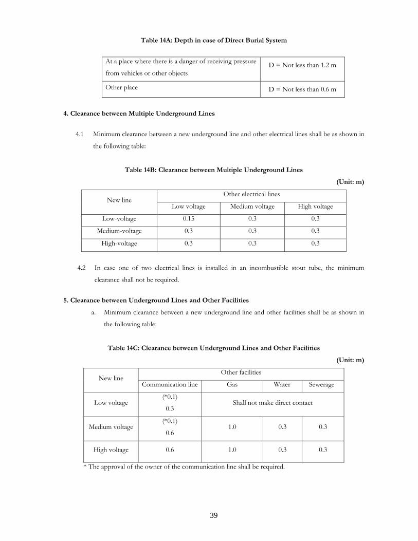
Table 14A: Depth in case of Direct Burial System
At a place where there is a danger of receiving pressure
from vehicles or other objects D = Not less than 1.2 m
Other place D = Not less than 0.6 m
4. Clearance between Multiple Underground Lines
4.1 Minimum clearance between a new underground line and other electrical lines shall be as shown in
the following table:
Table 14B: Clearance between Multiple Underground Lines
(Unit: m)
Other electrical lines New line
Low voltage Medium voltage High voltage
Low-voltage 0.15 0.3 0.3
Medium-voltage 0.3 0.3 0.3
High-voltage 0.3 0.3 0.3
4.2 In case one of two electrical lines is installed in an incombustible stout tube, the minimum
clearance shall not be required.
5. Clearance between Underground Lines and Other Facilities
a. Minimum clearance between a new underground line and other facilities shall be as shown in
the following table:
Table 14C: Clearance between Underground Lines and Other Facilities
(Unit: m)
Other facilities New line
Communication line Gas Water Sewerage
Low voltage (*0.1)
0.3 Shall not make direct contact
Medium voltage (*0.1)
0.6 1.0 0.3 0.3
High voltage 0.6 1.0 0.3 0.3
* The approval of the owner of the communication line shall be required.

40
b. In case the electrical line is installed in an incombustible stout tube and the tube does not come
into direct contact with other facilities, the minimum clearance shall not be required.
c. In case communication lines are united with electrical lines, the minimum clearance shall not be
required.
6. Connection of Underground Cables
The connection of underground cables shall be implemented with the following methods, in addition to
Article 26 of these SREPTS.
a. The connecting device shall be able to withstand the external forces that will be extended under
the expected conditions.
b. The connected cables shall be in good order for the permissive current of the original cables.
c. The connected cables shall have same waterproof performance.
7. Structure of Underground Boxes
In case underground boxes are installed, their structure shall be as follows:
a. The underground boxes shall be able to withstand the pressure of vehicles and other heavy
objects.
b. When there is some possibility that explosive gases or combustible gases are filled in the box
and the capacity of the box is 1m3 or more, a device such as a ventilator to exhaust the gases
shall be installed.
c. The lids of underground boxes shall be so installed that third persons are unable to open them
easily.
8. Grounding for Underground Facilities
Safety grounding of Class D shall be installed at the metallic part of such facilities as the tube, culvert and
joint box, and the metallic shield tape of a cable.

41
CHAPTER 3
HIGH-VOLTAGE TRANSMISSION
FACILITIES

42
Article 30: Protective Devices for Electrical Equipment
1. Measures for protecting Conductors and Electrical Equipment against Over-current
At necessary points in electrical circuits, over-current circuit breakers that protect against heating damage by
over-current and prevent outbreaks of a fire shall be installed.
2. Protection and Alarm Devices for Transformers and Reactive Power Compensators
Transformers and reactive power compensators to be installed in stations and high-voltage and medium-
voltage users’ sites shall be equipped with devices to automatically cut off the transformer and the reactive
power compensator from the electrical circuit when any abnormality that might cause significant damage and
serious trouble to the supply of electric power occurs, in addition to other appropriate protection systems, as
shown in Table 15.
Table 15: Protection Systems for Transformers and Reactive Power Compensators
Protection and alarm device
Classification Abnormality Automatic
shutdown device
Alarm
device
Over current ---
Internal fault --- Common
Significantly rise in temperature ---
Main
transformer
Transformer with cooling system
(A cooling system in which the
coolant is sealed-in to directly
cool the windings and iron core
of the transformers, and is
forcibly circulated)
When the cooling system fails or
when there is a significant rise in
the temperature of the
transformer
---
Power
capacitor Common
Over current or over voltage
or internal fault ---
Over current ---
Internal fault --- Common
Significant rise in temperature ---
Shunt
reactor
Shunt reactor with cooling
system (A cooling system in
which the coolant is sealed-in to
directly cool the winding and
iron core of the shunt reactor,
and is forcibly circulated)
When the cooling system fails or
when there is a significant rise in
the temperature of the Shunt
reactor
---
Notes- : Equips
-- : No need

43
Article 31: Design of Supporting Structures of Overhead High-voltage Lines
1. Basic Conditions
a. Supporting structures of overhead lines shall be designed, taking into account the following loads.
Table 16A: Type of Loads
Type of Load Components of Load
Weight of the supporting structure
Weight of the conductors and the ground wires and the accessories supported by the
supporting structure
Weight of the insulator strings and the fittings supported by the supporting structure Vertical loads
A vertical component of the maximum tension of the guy wires supporting the
supporting structure, if any
Wind pressure on the supporting structure under the maximum wind velocity
Wind pressure on the conductors and the ground wires supported by the supporting
structure under the maximum wind velocity
Wind pressure on the insulator strings and the fittings supported by the supporting
structure
Horizontal
transverse loads
A horizontal transverse component of the maximum tension of the conductors and
the ground wires supported by the supporting structure and the guy wires supporting
the supporting structure, if any
Wind pressure on the supporting structure under the maximum wind velocity Horizontal
longitudinal
loads
A horizontal longitudinal component of the unbalanced maximum tension of the
conductors and the ground wires supported by the supporting structure and the
maximum tension of the guy wires supporting the supporting structure, if any
b. Supporting structures and foundations of overhead high-voltage lines shall be designed, taking the
value of wide pressure based on the reference wind velocity prescribed in Article 27 of these
SREPTS into consideration.
c. Supporting structures and foundations of overhead high-voltage lines shall be designed to withstand
the maximum loads, taking appropriate safety factors into consideration.
d. In case overhead high-voltage lines are installed at places with the worst conditions, such as inside
river areas, windy areas, and so on, the supporting structures and the foundations shall be designed
to withstand such severe conditions.

44
2. Components of Supporting Structures
Components of supporting structures shall satisfy the following or shall have an equivalent strength to these
items.
2.1 Fundamental Properties of Components of Supporting Structures
Flat steel, shaped steel, steel pipes, steel plates, steel bars and bolts which compose a steel tower or an
iron pole used for overhead transmission lines shall be appropriate ones as specified in the ISO
(International Organization for Standardization) standards or other standards equivalent to these
standards.
2.2 Thickness of Steel Members etc.
Shaped steel, steel pipes and steel plates to be used for a steel tower or an iron pole for overhead
transmission lines shall have the thickness and other dimensions specified below.
2.2.1 Minimum Thickness of Shaped Steel
a. Those to be used as a main post member of an iron pole (in which a main member of a
cross arm is included. The same shall apply hereafter in this article) shall have a thickness of
4 mm.
b. Those to be used as a main post member of a steel tower shall have a thickness of 5 mm.
c. Those to be used as other structural members shall have a thickness of 3 mm.
2.2.2 Minimum Thickness of Steel Pipes
a. Those to be used as a main post member of an iron pole shall have a thickness of 2 mm.
b. Those to be used as a main post member of a steel tower shall have a thickness of 2.4 mm.
c. Those to be used as other structural members shall have a thickness of 1.6 mm.
2.2.3 Slenderness Ratio of Steel Members
The slenderness ratio of a steel member is an indicator showing the state of tallness of its form.
Slenderness Ratio of steel member is a division of its length to its section turning radius. More
slenderness ratio means longer length or smaller section, so the form of steel member is more
slim and weaker. Lesser slenderness ratio means shorter length or bigger section, so the form of
steel member is more rotund and stronger.
The slenderness ratio of a compression member shall be not more than 200 for those to be used
as the main post members, not more than 220 for compression members other than main post
members (excluding those used as auxiliary members) and not more than 250 for those used as
auxiliary members.
2.2.4 Minimum Thickness of Steel Plates The thickness shall be not less than 1 mm.

45
2.3 Strength of Steel Members and Bolts
Steel members and bolts to be used for a steel tower or an iron pole of overhead transmission lines shall have
the strength as specified in Table 16B.
Table 16B: Strength of Steel Members and Bolts
Classification of strength Strength
When σY≤ 0.7σB σY Tensile strength
When σY > 0.7σB 0.7σB
Compression strength σY
Flexural strength σY
When σY≤ 0.7σB σY / 3 Shearing strength
When σY > 0.7σB 0.7σB / 3
Bearing strength 1.65σY
0 < λk < Λ ( )( ) ( )( ) σ λ π σ λ π σY K K E Y K E Yk k0 1 2
2
− −⎡
⎣⎢
⎤
⎦⎥
Buckling strength Λ≤λk 1.5π2E / 2.2λk2
Where:
σY: Yield point strength of steel members and bolts
σB: Tensile strength of steel members and bolts
λk: Effective slenderness ratio ( = Lk / r )
Lk: Effective buckling length of steel members
r: Turning radius of a steel member cross section
E: Elastic modulus (20.6 × 10² N/m2)
Λ: ( )π σ15 2 2. .E K Y
K, K0, K1, K2: Refer to Table 16C.
Table 16C K, K0, K1, K2, for Table 16B
K K0 K1 K2
Structural members with little decentering (steel pipe,
cruciform section steel, etc.) 0.6 1 0 0.352
Structural members with some decentering (angle steel
used for a main post member, etc.) 0.5 0.945 0.0123 0.316
Structural members with significant decentering (angle steel
used for a web member with one side flange joint, etc.) (*) 0.3 0.939 0.424 0
(*) Note that the buckling strength shall be not more than 0.6σY for structural members with significant
decentering.

46
2.4 Strength of Foundation Components used for Steel Poles or Steel Towers
Foundation components of a steel pole or steel tower for overhead transmission lines shall have the
strength specified below:
a. Strength of Concrete
The strength of concrete at yield point shall be based on the design standard strength (4-week
strength; Fc) of concrete and conform to Table 16D.
Table 16D: Strength of Concrete
Kind of strength Strength of concrete [×106N/m2]
Compression strength Fc/2
Tensile strength Fc/20
Shearing strength Fc/20 and 0.74+1.5Fc/100
b. Bond Strength of Concrete
The bond strength of concrete at yield point shall be based on the design standard strength (4-
week strength; Fc) and conform to Table 16E.
Table 16E: Bond Strength of Concrete
[×106N/m2]
Member
Upper edge round
bar
Normal round bar Fixative joint
Round bar 6Fc/100 and not
more than 1.32
9Fc/100 and not more
than 1.99
6Fc/100 and not more than 1.32
Deformed
round bar
Fc/10 and not more
than 1.32+3Fc/75
3Fc/20 and not more
than 1.99+3Fc/50
Fc/10 and not more than
1.32+3Fc/75
Shaped steel 3Fc/100 and not more than 0.66
c. Strength of Shaped Steel, Flat Steel and Steel Bars
The strength of shaped steel, flat steel and steel bars at yield point shall conform to Table 16F.

47
Table 16F: Strength of Shaped Steel, Flat Steel and Steel Bars
Yield tensile strength
(N/mm2)
Yield compression strength
(N/mm2)
Round bar σY and not more than 234 σY and not more than 234
Diameter≥ 29 mm σY and not more than 294 σY and not more than 294
29 mm > Diameter > 25 mm σY σY Deformed
round bar
25 mm≥Diameter σY and not more than 322 σY and not more than 322
Others σY and not more than
0.7σB σY
σY: Strength of material at yield point
σB: Tensile strength of material
d. Strength of Bolts
The strength of bolts shall conform to Table 16B.
3. Wind Pressure Load
3.1 Wind Pressure Values
The wind pressure load shall be the value obtained by calculation based on the wind pressure specified in
the following Table 16G.
This shall not apply when calculation is made based on values obtained by a wind pressure (wind duct)
test using a wind at a velocity of not less than 32 m/s.
The wind receiving area shall be the vertical projected area of the structural member. For crossarms of a
concrete pole, an iron pole except a columnar pole, and a steel tower, the wind receiving area shall be the
vertical projected area of the front structures that receive the wind.

48
Table 16G: Wind Pressure to calculate the Wind Pressure Load
Subject to the wind pressure Wind pressure to 1 m2 of the vertical
projected area of the structural member (N)
Columnar pole 520
Triangle or rhombic pole 1,220
Square pole consisting of
steel pipes 970 Iron pole
Others 1,540
Columnar pole 520 Reinforced
concrete pole Square pole 1,290
Shaped steel tower 2,350 *
Steel pipe tower 1,340 *
Columnar pole 520
Supp
ortin
g st
ruct
ure
Steel tower Single
pole Hexagonal or
octagonal pole 970
Electrical wires forming multiple conductors
(limited to those in which two compositional
conductors are arranged horizontally and the
distance between such electrical conductors is
not more than 20 times their outer diameter)
610
Elec
trica
l co
nduc
tors
an
d ot
her w
ires
Others 680
Insulator device 900
1,030 when it is used as a single member Crossarms for an iron pole (limited to a columnar pole)
and a reinforced concrete pole 1,410 in other cases
* This value shall be applied to 115kV high-voltage towers which are less than 40m high.
3.2 Wind Pressure Load at an Oblique Wind When the wind blows to the electrical line at an angle of 60°, the wind pressure load in an assumed
normal load of a common type steel tower shall be that calculated by the wind pressure load multiplier
(in case of a square tower) in Table 16H.

49
Table 16H: Multiplier to Wind Pressure Load
Classification of wind pressure load
The multiplier to the wind pressure load when
the wind blows perpendicular to the electrical
line (in case of a square tower)
Shaped steel tower 1.6 Wind pressure
load to body Steel pipe tower 1.4
Wind
pressure
load to steel
tower Wind pressure load to cross arm
0.5 (for the wind pressure in the direction of
the electrical line)
Wind pressure load to wire 0.75
4. Loads on Supporting Structures and Safety Factors
Loads on supporting structures and safety factors shall satisfy the following items or shall have an equivalent
performance to these items.
4.1 Types and Combinations of Assumed Loads
The types and combinations of assumed loads to be used for calculating the strength of supporting
structures for overhead transmission lines shall conform to the following provisions.
The assumed loads on supporting structures shall be classified as the loads specified in Table 16I. The
combination of these loads on the supporting structures shall be in accordance with Table 16J depending
on the classification and type of supporting structures.
Table 16I: Classification of Assumed Loads on Supporting Structures
Type of Load Contents Symbol
Weight of the supporting structure Wt
Weight of the conductors and the ground wires and the accessories supported by the supporting structure Wc
Weight of the insulator strings and the fittings supported by the supporting structure Wi
A vertical component of the maximum tension of the conductors and the ground wires Va
Vertical loads
A vertical component of the maximum tension of the guy wires supporting the supporting structure, if any Ws
Wind pressure on the supporting structure under maximum wind velocity Ht
Wind pressure on the conductors and the ground wires supported by the supporting structure under the maximum wind velocity Hc
Horizontal transverse
loads
Wind pressure on the insulator strings and the fittings supported by the supporting structure Hi

50
A horizontal transverse component of the maximum tension of the conductors and the ground wires supported by the supporting structure and the guy wires supporting the supporting structure, if any
Ha Hs
A torsional load due to the unbalance of the maximum tension of conductors of any phase q
Wind pressure on the supporting structure under the maximum wind velocity Ht'
A horizontal longitudinal component of the maximum tension of the guy wires supporting the supporting structure, if any Ws'
The unbalance of the maximum tension of the conductors of all phases and the ground wires P1
The unbalance of the maximum tension of the conductors of any phase P2
Horizontal longitudinal loads
A torsional load due to the unbalance of the maximum tension of the conductors of any phase q1
Table 16J: Combination of Loads on the Supporting Structures
Design cases Combination of assumed loads
Vertical load Horizontal transverse
load
Horizontal
longitudinal load
Classifica-
tion of
supporting
structure
Type Load
condi-
tion
Wind
direction Wt Wc, Wi Va Ws Ht Hc, Hi Ha Hs q H’t P1 P2 q1 W's
Horizontal
transverse
Tension &
Suspen -
sion Type
Tower
Normal Horizontal
longitudinal
Horizontal
transverse
Concrete
pole
Steel pole Dead-end
Type Tower Normal
Horizontal
longitudinal
Horizontal
transverse/60°
Normal Horizontal
longitudinal
Horizontal
transverse
Tension &
Suspen-
sion Type
Tower Abnor-
mal Horizontal
longitudinal
Horizontal
transverse
Normal Horizontal
longitudinal
Horizontal
transverse
Steel tower
Single steel
pole Dead-end
Type Tower
Abnor-
mal Horizontal
longitudinal

51
Where:
Dead-end type: Supporting structure with a large unbalanced load in the horizontally
longitudinal direction, e.g. the first tower from a substation.
Abnormal Condition: An assumption for tower design where any one or two of conductors and
ground wires will be broken down
Notes: Circles " " indicate the assumed loads to be considered at the same time that
can combine together.
The wind direction that brings the bigger assumed load should be selected.
Where strung wires are arranged asymmetrically on the supporting structure, the assumed vertical
eccentric load shall be added to the load in Table 16J and the load by normal torsional load shall
also be added for the dead-end type.
4.2 Unbalanced Maximum Tension and so on
Unbalanced maximum tension and so on used in 4.1 shall conform to the following requirements:
4.2.1 The unbalanced maximum tension and torsional force shall conform to Table 16K.
Table 16K: Unbalanced Tension and Torsional Force
Unbalanced tension and torsional force Classification of
supporting structure
Type of supporting structure Assumed normal load Assumed abnormal load
Tension & Suspension Type
Tower No specification
Steel tower
Dead-end Type Tower
Horizontal longitudinal component of force of the unbalanced tension equal to the assumed maximum tension for each strung wire
Horizontal longitudinal component of force of the unbalanced tension and torsional force generated by cutting strung wires
Tension & Suspension Type
Tower No specification
Iron reinforced
concrete pole and iron pole Dead-end Type
Tower
Horizontal longitudinal component of force of the unbalanced tension equal to the assumed maximum tension for each strung wire
No specification

52
4.2.2 For steel towers, the strung wires shall be cut according to the following requirements, depending on
the total number of phases of electrical conductors (which mean phases for each circuit. The same
shall apply hereafter).
a. The overhead ground wire shall not be cut at the same time as the electrical conductors and
only one wire shall be cut;
b. Where the total number of phases of electrical conductors is not more than twelve (12), one
phase that maximizes the stress generated in each structural member (two electrical
conductors from one phase in case of multiple conductors for steel towers other than dead-
end type);
c. Where the total number of phases of electrical conductors is over twelve (12) (excluding the
case specified in the following Item d.), two phases in different circuits that maximize the
stress generated in each structural member (two electrical conductors from one phase in case
of multiple conductors for steel towers other than dead-end type);
d. Where electrical conductors are arranged so that nine or more phases are in a longitudinal
row and two phases are in a transverse row, one of the top six phases in the longitudinal row
(two electrical conductors from one phase in case of multiple conductors for steel towers
other than dead-end type) and one phase from the other phases (two electrical conductors
from one phase in case of multiple conductors for steel towers other than dead-end type) that
maximize the stress generated in each structural member.
4.2.3 The unbalanced tension generated by cutting the strung wire shall be equal to the assumed maximum
tension.
Provided,however, that the unbalanced tension may be 0.6 times the assumed maximum tension if,
depending on the mounting method of the strung wire, the supporting point of the strung wire shifts
when the wire is cut or the strung wire slides at the supporting point.
4.3 Safety Factor of Supporting Structure
The yield strength of the structural members of reinforced concrete poles, iron poles and steel towers
used for overhead transmission lines shall satisfy the safety factor listed in Table 16L for the assumed
loads specified in 4.1 to 4.2.
Table 16L: Safely Factors of Supporting Structures
Classification of supporting structure Load condition Safety factor
Reinforced concrete pole
Iron pole Assumed normal load 2.0
Steel tower Assumed normal load 1.5

53
Assumed abnormal load 1.0 (1.5 for crossarms)
5 Loads on Foundations of Supporting Structures and Safety Factors
5.1 Loads on the Foundation of a Supporting Structure
The loads applied to the foundation of a supporting structure for overhead transmission lines shall be
calculated from combinations of the assumed loads of the supporting structure specified in paragraph 4
and the resulting maximum values shall be the assumed normal and abnormal loads for the foundation.
5.2 Safety Factor of the Foundation
The safety factor of the foundation of a supporting structure for overhead transmission lines shall
satisfy the value listed in Table 16M for its yield strength.
Table 16M: Safety Factors of the Foundations
Safety factor Classification of supporting structure
Assumed normal load Assumed abnormal load
Reinforced concrete pole and iron pole 2.0 -
Steel tower 2.0 1.33
5.3 Treatment of the Weight of the Foundation
The weight of the foundation used for calculating the safety factor shall be treated in accordance with
the following provisions:
a. For a foundation that is subject to a lifting load, not more than two-thirds of the weight of
the foundation (or the weight of the foundation of a steel tower to an abnormal load) may be
included in the lift bearing power.
b. For a foundation that is subject to a compressive load, the weight of the foundation shall be
included in the compressive load.
Article 32: Design of Fittings for Conductors and/or Ground Wires of Overhead High-voltage Lines
1. Safety Factor of Fittings for Conductors and/or Ground Wires of Overhead High-voltage Lines
1.1 The safety factor for the tensile strength (the maximum tensile strength or breaking strength) of
fittings of conductors and ground wires for overhead high-voltage lines shall be 2.5 or more.
1.2 The safety factor mentioned in 1.1 shall be obtained as follows:
a. Tension insulator device (insulator device that anchors electrical conductors)

54
[Safety factor] = [Tensile break strength] / [Assumed maximum tension at a support point];
b. Suspension insulator device (Insulator device from which electrical conductors are hung)
[Safety factor] = [Tensile break strength] / [Composite load of vertical load and horizontal
transverse load];
c. Supporting insulator device
[Safety factor] = [Bending break strength] / [Horizontal transverse load or vertical load applied
perpendicular to the axis of the insulator device].
2 Mechanical Strength of Insulators for Overhead Transmission Lines
2.1 Assumed Load
The assumed loads to be used for calculating the strength of insulator devices for overhead transmission
lines shall conform to the following requirements.
a. Vertical Load
The vertical load shall be the sum of the weight of electrical conductors, the weight of insulator
devices and the vertical component of the force generated by the assumed maximum tension of
the electrical conductors.
b. Horizontal Transverse Load
The horizontal transverse load shall be the sum of the wind pressure loads of electrical
conductors and insulator devices and the horizontal component of load generated by the assumed
maximum tension of the electrical conductors. The wind pressure loads shall be calculated based
on the values listed in Table 16G.
c. Assumed Maximum Tension of Conductors
The assumed maximum tension of conductors shall be the tension of the transmission
conductor under the composite load of the vertical load generated by the weight of the electrical
conductor, and the horizontal load generated by the horizontal wind pressure stipulated in Table
16G at the average temperature in the area.
Article 33: Protection against Lightning for Overhead High-voltage Lines
The following measures shall be taken for overhead high-voltage lines to decrease the number of electrical
faults and to protect equipment from damage caused by the faults.
a. Installation of ground wires for overhead high-voltage lines;
b. Installation of arcing horns for both ends of insulator assemblies of overhead high-voltage lines;
c. Installation of armor rods to wrap conductors in a clamp of suspension insulator assemblies of
overhead high-voltage lines.

55
Article 34: Bare Conductors of Overhead High-voltage Lines
1. Vibration Dampers
An appropriate type and number of dampers shall be installed to prevent fatigue of bare conductors and
ground wires for overhead high-voltage lines due to their aeolian vibration.
2. Connection
In case bare conductors and ground wires are jointed with each other or with insulated conductors or cables,
the connection shall conform to the following requirements in addition to Article 26 of these SREPTS.
a. Bare conductors and ground wires shall be connected with compression type sleeves or
compression type devices.
b. The tensile strength of connection of bare conductors and ground wires shall be not less than 95 %
of the tensile strength of the connected bare conductors and ground wires. This requirement,
however, shall not be applied to cases where the maximum tension to be designed is substantially
less than the ultimate strength of the bare conductors and ground wires such as jumper conductors,
the end span to substations and others.
Article 35: Clearance between Bare Conductors and Supporting Structures of Overhead High-voltage
Lines
Clearance between bare conductors and supporting structures, arms, guy wires and/or pole braces of
overhead high-voltage lines shall be as follows. The clearances shall be secured, in any cases where the
maximum swing of conductors under the maximum wind velocity to be designed.
Table 17: Clearance between Bare Conductors and Supporting Structures
Nominal Voltage Clearance
115kV Not less than 0.70m
230kV Not less than 1.45m
Clearance between ground wires and the nearest conductor in the same span shall be larger at any point in the
span than the clearance of the supporting point at both sides of the span.
Article 36: Height of Overhead High-voltage Lines
The height of conductors of overhead high-voltage lines shall be as follows:

56
1. Height in Urban Areas
Height of conductors of overhead high-voltage lines in urban areas shall be not less than the value
calculating by adding 0.060 m to a base height 6.5m for every 10kV over 35kV.
Table 18A: Height in Urban Areas
Nominal Voltage Height
115kV Not less than 7.0m
230kV Not less than 7.7m
2. Height in Areas Where Third Persons Hardly Approach
The height of conductors of overhead high-voltage lines in areas where third persons hardly approach shall be
not less than the value calculated by adding 0.06 m to a base height of 5.5m for every 10kV over 35kV.
Table 18B: Height in Areas Where Third Persons Hardly Approach
Nominal Voltage Height
115kV Not less than 6.0m
230kV Not less than 6.7m
3. Height over Roads and/or Railways
The height of conductors of overhead high-voltage lines crossing over roads and/or railways shall be not less
than the value calculated by adding 0.060 m to a base height of 13m for every 10kV over 35kV.
Table 18C: Height over Roads and/or Railways
Nominal Voltage Height
115kV Not less than 13.5m
230kV Not less than 14.2m
4. Height over Rivers and/or Seas
The height of conductors of overhead high-voltage lines crossing rivers and/or seas shall be as follows:

57
Table 18D: Height over Rivers and/or Seas
At places with no vessel passage At places with vessel passage
From the highest water level From the highest point of vessels on the
highest water level(*1)
Not less than the value calculated by adding
0.06 m to a base height of 5.5m for every 10kV
over 35kV
Not less than the value calculated by adding
0.06 m to a base height of 3m for every 10kV
over 35kV
Nominal Voltage Height Nominal Voltage Clearance
115kV Not less than 6.0m 115kV Not less than 3.5m
230kV Not less than 6.7m 230kV Not less than 4.2m
(*1) The highest point of vessels shall be decided taking into account any future possible changes.
5. Note
All the heights described above shall be secured in any cases of the maximum sagging of conductors in the
maximum temperature to be designed.
Article 37: Clearance between Overhead High-voltage Lines and Other Facilities or Trees
1 Generals
The clearance between each conductor of overhead high-voltage lines and other facilities or trees shall be as
follows:
a. Clearance to Other Facilities
The clearance between each conductor of overhead high-voltage lines and other facilities shall be
not less than the value calculated by adding 0.06 to a base height of 3m for every 10kV over 35kV.
Table 19A: Clearance to Other Facilities
Nominal Voltage Height
115kV Not less than 3.5m
230kV Not less than 4.2m

58
b. Clearance to Trees
The clearance between each conductor of overhead high-voltage lines and trees shall be not less
than the value calculated by adding 0.06 m to a base height of 2m for every 10kV over 35kV.
Table 19B: Clearance to Trees
Nominal Voltage Height
115kV Not less than 2.5m
230kV Not less than 3.2m
c. Note
The clearances described above shall be secured in any cases of the maximum sagging of
conductors in the maximum temperature and/or the maximum swing of conductors under the
maximum wind velocity to be designed.
Figure 7: Direct Proximity
Other facilities
Clearance
Support
Clearance
<Condition of Conductors> -At the maximum temperature -Maximum swing angle under the maximum
wind speed

59
2 Proximity to and Crossing with Buildings
2.1 230kV Overhead High-voltage Line
Overhead transmission conductors with a nominal voltage 230kV shall be installed not less than 3
meters away in a horizontal distance above or to the side of buildings.
Figure 8: Proximity to Buildings (230kV)
2.2 115kV Overhead High-voltage Line
Overhead transmission conductors with a nominal voltage of 115kV shall be installed not less than
6 meters from the top of buildings when the 115kV overhead high-voltage line is adjacent laterally
within 3m or crossing with buildings.
Support
Building
Horizontal distance: Not less than 3m

60
Figure 9: Crossing with Buildings (115kV)
3. Proximity to and Crossing with Medium-voltage Lines and High-voltage Lines
The clearance between each conductor of overhead high-voltage lines and other medium-voltage lines or
high-voltage lines shall be not less than the value calculated by adding 0.06m to a base height of 2m for every
10kV over 35kV.
Table 20: Clearance between Conductors
Nominal Voltage[kV] Clearance[m]
115 Not less than 2.5 Clearance (Ll*)
230 Not less than 3.2
* Refer to Figure 10.
Support
Building
Lb: not less than 6 m Lb: not less than 6m
3 m 3 m
Building

61
Figure 10: Proximity and Crossing with Medium-voltage Lines and High-voltage Lines
Article 38: Prevention of Danger and Interference due to Electrostatic Induction and Electromagnetic
Induction
1. Electrostatic Induction
High-voltage lines shall be installed to prevent danger to persons and/or interference on communication lines
installed near the high-voltage lines caused by electrostatic induction, taking appropriate measures including
the following items a, b and Article 28 of these SREPTS into consideration.
a. The electrical field caused by overhead high-voltage lines shall be 3kV/m or less at 1 m above the
ground surface, except for overhead high-voltage lines in places where third persons hardly
approach, such as in mountains, on farming land and so on.
b. Conductive materials on the surface of the buildings under overhead high-voltage lines shall be
grounded with the Class D grounding in accordance with Article 22 of these SREPTS.
2. Electromagnetic Induction
High-voltage lines shall be installed to prevent danger to persons and/or interference on communication lines
caused by electromagnetic induction on the low voltage lines and/or communication lines installed near the
high-voltage lines, taking appropriate measures including Article 28 of these SREPTS.
Medium-voltage or high-voltage line
Support
L1

62
Article 39: Surge Arresters
1. Generals
Surge arresters shall be installed at the appropriate places on electrical lines.
2. Installation of surge arresters
2.1 Installation Points for Surge Arresters
In high-voltage and medium-voltage electrical circuits surge arresters shall be installed at the points
listed below or at locations close to such points, in order to prevent damage to be electrical
equipment installed in electrical circuits in the power stations, substations and switching stations
and high-voltage and medium-voltage users’ sites, by over-voltage.
However, the same shall not apply in cases where there is no risk of damage to such electrical
equipment.
a. Receiving and outgoing points on overhead electrical lines in the power stations,
substations and switching stations;
b. Receiving points on the high-voltage and medium-voltage users’ sites to which power is
supplied from high-voltage and medium voltage overhead electrical lines;
c. Locations where there is a risk that the protective effects of surge arresters installed in
accordance with the above provisions may not be achieved.
Figure 11: Installation Points for Surge Arresters
Substation
User
230kV, 115 kV 22kV
UsersUsers
Users
230V, 400V
230V, 400V
Surge arrester
Power station, substation or
switching station

63
2.2 Grounding of Surge Arresters
Grounding of surge arresters shall be installed in accordance with Article 22 and 23 of these
SREPTS.
The grounding resistance provided for surge arresters in high-voltage and medium-voltage
electrical circuits in power stations, substations, switching stations and high-voltage and medium-
voltage users’ sites shall be as much lower than 10 Ω as possible in order to prevent hinder to the
functions of the surge arrester.

64
CHAPTER 4
MEDIUM AND LOW-VOLTAGE
DISTRIBUTION FACILITIES

65
Article 40: Supporting Structures
1. Loads on Overhead Distribution Lines
Supporting structures of overhead medium-voltage and low-voltage lines shall be designed taking into account
the loads shown in Table 21A.
Table 21A: Kinds of Loads
Type of Load Contents
Weight of supporting structures
Weight of the conductors and the ground wires and the accessories supported by
the supporting structure
Weight of the insulating devices, the crossarms and the distribution equipment
supported by the supporting structure
Vertical loads
A vertical component of the maximum tension of the guy wires supporting the
supporting structure, if any
Wind pressure on the supporting structure under the maximum wind velocity
Wind pressure on the conductors and the ground wires supported by the
supporting structure under the maximum wind velocity
Wind pressure on the insulator, the crossarms and the distribution equipment
supported by the supporting structure under the maximum wind velocity
Horizontal
transverse loads
A horizontal transverse component of the maximum tension of the conductors
and the ground wires supported by the supporting structure and the guy wires
supporting the supporting structure, if any
Wind pressure on the supporting structure under the maximum wind velocity
Horizontal
longitudinal loads
A horizontal longitudinal component of the unbalanced maximum tension of the
conductors and the ground wires supported by the supporting structure and the
maximum tension of the guy wires supporting the supporting structure, if any
By calculating, firstly, the load when wind pressure is applied in a horizontal transverse direction to the
distribution line, and secondly, the load when wind pressure is applied in the horizontal longitudinal direction
of the distribution line, the one of these two loads which generates greater stress on the structural member
shall be adopted for the assumed normal load.
2. Safety Factor of Foundations of Supporting Structures
- The safety factor of the foundations of supporting structures for low-voltage lines shall be 2 or more
to the wind pressure.

66
- The safety factor of the foundations of supporting structures for medium-voltage lines shall be 2 or
more to the load prescribed in Table 21A.
- If wooden poles, iron-poles and iron-reinforced concrete poles are installed at other than soft ground
in accordance with Table 21B, this article may not be applicable.
Table 21B
Design load of
poles Length of poles Setting depth Span
15m or less 1/6 of overall length or more
Woo
den
pole
---- More than 15m,
and 16m or less 2.5m or more
Medium-voltage
lines in an urban
area: Not more
than 75m
15m or less 1/6 of overall length or more
Iron
pol
e
---- More than 15m,
and 16m or less 2.5m or more
15m or less 1/6 of overall length or more
More than 15m,
and 16m or less 2.5m or more
Iron
-rein
forc
ed
conc
rete
pol
e
6.5kN or less
More than 16m,
and 20m or less 2.8m or more
Low-voltage lines
in an urban area:
Not more than
40m
Other: Not more
than 150m
3. Strength of Iron-reinforced Concrete Pole
- Iron-reinforced concrete poles for low-voltage lines shall have the strength to withstand wind
pressure.
- Iron-reinforced concrete pole for medium-voltage lines shall have the strength to withstand the load
prescribed in Article 31 of these SREPTS.
- Iron-reinforced concrete pole shall have the strength to withstand two times of the design load.
4. Safety Factor of conductors and supporting structures
4.1 Conductor
A safety factor of 2.5 or more shall be applied to the tensile strength (ultimate tensile strength; breaking
strength) of overhead distribution conductors and overhead ground wires.

67
4.2 Supporting Structure
(1) Supporting structures for overhead low-voltage lines shall have the strength to withstand a
load of 1.2 times the wind pressure for wooden poles, and a load equal to the wind pressure
for others.
(2) Wooden poles to be used as the supporting structures for overhead medium-voltage lines
shall be installed in accordance with the following items:
a. The safety factor against a wind pressure shall be 1.5 or more; and
b. The thickness shall be not less than 12 cm in diameter at the top end.
(3) Iron-reinforced concrete poles and iron poles to be used as supporting structures for
overhead medium-voltage lines shall have the strength to withstand the assumed normal
load.
5. Reference Wind Velocity
Reference wind velocity used in the calculation of wind loads on overhead distribution lines shall be as
follows:
Table 21C: Reference Wind Velocity
Yearly maximum of 10-minute average wind velocity
(50 year return period) 32m/sec
In the following circumstances, the above reference wind velocity shall be changed:
a. When sufficient observed wind velocity data have been accumulated.
b. When greater reliability is particularly needed.
c. When a terrain has the effect to decrease the wind velocity.
6. Reinforcement for Supporting Structures by Guys
Supporting structures shall be guyed to share strength with the guys according to Table 21D. In such case, the
strength of the supporting structure itself shall be such that it bears at least half of the wind load.
6.1 Installation and Safety Factor of Guys
a. Installation of Guys

68
Guys shall be installed in order to reinforce the foundation of a supporting structure if the calculated
result of the safety factor of supporting structure’s foundation is less than 2.0 under the following
conditions.
Table 21D: Conditions of Installation of Guys
Conditions Installation method Safety factor
of the guy
a. Supporting
structures lacking strength against
wind pressure
Guys that withstand wind pressure shall be
installed at right angle to the lines. 2.5 or more
b. Supporting structure of which
spans on both sides are too
different
Guys that withstand the force caused by
unbalanced tension shall be installed on both
sides in the direction of the line.
1.5 or more
c. Supporting structure of which lines
on both sides make an angle of
more than 5 degrees
Guys that withstand the force caused by the
assumed maximum tension of each line shall
be installed at the opposite side of the line.
d. Supporting structure which
supports the end of a line
Guys that withstand the assumed maximum
tension of the line shall be installed at the
opposite side of the line.
1.5 or more
b. Section near the Ground of the Guy
For the section near the ground, that is, from the underground portion of the guy to 30cm above the
ground, a galvanized iron rod or similar rod equal or superior to it in strength and corrosion
resistance shall be used.
c. Foundation of the Guy
The guy anchor shall be installed firmly so that it can adequately bear the tensile load from the guy. A
guy anchor installed with a supporting structure shall be of such a material that it hardly corrodes.
d. Globe Insulator
If a guy is installed on an overhead distribution line that is in danger of touching an electrical
conductor, a globe insulator shall be inserted in the upper part of the guy.
A globe insulator, however, need not be inserted if the guy is installed on a low-voltage overhead
distribution line in a place other than a rice field or other swamp area.

69
e. Height of Guy
A guy crossing a road shall have a height of not less than 6.5 m from the road surface. If this is
impossible for technical reasons, a height of not less than 4.5m (not less than 2.5m, if a sidewalk) is
allowed if there is no danger of interfering with traffic.
f. Strut
A strut that has equivalent or higher effect than a guy can be substituted for a guy.
Article 41: Overhead Medium-voltage and Low-voltage Lines
1. Cables for Overhead Lines
a. When cables are used for overhead lines, the cables shall be installed using messenger wires or
other appropriate measures so that they bear no tensile strength. The messenger wires shall be
installed in accordance with the provision of Article 32 of these SREPTS.
b. When cables are installed along a building or another object, the cables shall be supported so that
they are not damaged by contacting the building or the object.
2. Connecting Methods of Overhead Conductors
The tensile strength of the conductors shall not be reduced by 20% or more, when electric conductors are
connected. If the tension on the conductors is distinctly less than the general tensile strength of conductors,
this may not apply.
3. Branching of Overhead Lines
Branching of overhead lines shall be made at the supporting point of the lines. If branching can be done in a
way that does not to inflict tension on the conductor at the branch point, this may not be applicable.
Article 42: Mechanical Strength of Insulators
1. Generals of Mechanical Strength of Insulators
The insulator to support medium-voltage lines shall be installed in such a manner that it has sufficient strength
to attain the safety factor of at least 2.5 based on the assumption that the following loads are exerted on the
insulators.
a. For the insulators to anchor lines, the load is the assumed maximum tension of the lines.
b. For the insulators to support lines, the load is the horizontal lateral load or vertical load exerted
perpendicular to the axis of the insulators.

70
2. Safety factor of Insulators
The safety factor of insulators for medium-voltage lines shall be calculated using the following equations.
a. Tension insulator (Insulator that anchors electrical conductors)
[Tensile break strength]
[Safety factor] =
[Assumed maximum tension of the lines]
b. Supporting insulator
[Tensile break strength]
[Safety factor] = [Horizontal transverse load or vertical load applied perpendicular to the
axis of the insulator device]
3. Assumed Load
The assumed loads to be used for calculating the strength of insulator for medium-voltage lines shall conform
to the following requirements.
a. Vertical load
The vertical load shall be the sum of the weight of electrical conductors and the weight of insulator
devices.
b. Horizontal transverse load
The horizontal transverse load shall be the sum of the wind pressure loads of electrical conductors
and insulator devices and the horizontal component of a load generated by the assumed maximum
tension of the electrical conductors. The wind pressure loads shall be calculated based on the
values listed in Table 22.
Table 22: Wind Pressure Loads
Segment of an object receiving wind pressure Wind pressure to 1m2 of the vertical projected
area (Pa)
Electrical conductor and other strung conductor 680
Insulation device 900
*The wind pressures are obtained from 32m/s wind velocity as same as Table 21C.

71
4. Assumed Maximum Tension of the Lines
The assumed maximum tension of the lines shall be the tension of the medium-voltage line conductor under
the composite load of:
a. The load generated by the weight of the electrical conductor, and
b. The horizontal load generated by the horizontal wind pressure stipulated in Table 22.
Article 43: Medium-voltage/Low-voltage (MV/LV) Transformers
MV/LV transformers, including medium-voltage conductors other than cables, shall be installed so that they
are not in danger of electrical shock using either of the following methods.
1. MV/LV transformers shall be installed in an exclusive cabin that is locked.
2. MV/LV transformers shall be installed at a height of not less than 5.0m above the ground in order
that persons can not touch them easily.
3. Appropriate fences shall be installed around the MV/LV transformers in order that persons can not
touch them easily and warning signs to indicate the danger shall be displayed. Otherwise MV/LV
transformers, the charged parts of which are not exposed shall be installed so that persons can not
touch them easily.
Article 44: Installation of Distribution Transformers for Single Wire Earth Return (SWER) Systems
1. Grounding Arrangement for SWER
Grounding on the primary side of distribution transformers for SWER shall be installed by the following
methods, in order to avoid risk of danger to persons, domestic animals and other facilities due to the potential
difference between the grounding conductor and the ground caused by load current, when any failure occurs.
a. The grounding resistance shall be not more than 5ohms.
b. The cross-sectional areas of grounding conductors shall be not less than 16mm2.
c. The grounding conductors placed up to a depth of 75cm underground or up to a height of 2.0 m
above ground shall be covered by a synthetic resin pipe or another shield of equivalent or higher
insulating effect and strength.
d. The grounding for SWER installed on the primary side of a distribution transformer and the Class
B grounding for it shall be completely separated to keep the safety of low voltage line system.
2. Load Current of Distribution Transformers
The load current in any earth-return circuits shall be not more than 8 amperes.

72
3. Isolating Transformer
SWER circuits shall be supplied from double-wound transformers (isolating transformers).
4. Safety of Third Persons
Warning signs to alert third persons’ attention shall be installed near the grounding point.
Article 45: Protective Devices
1. Installation of Medium-Voltage Over-current Circuit Breakers
a. On medium-voltage lines, an over current circuit breaker shall be installed at the outgoing point of a
substation or similar location and on the primary side of a transformer.
b. Over current breakers for short circuit protection shall have the ability to break the short circuit
current that passes the breakers.
2. Installation of Medium-Voltage Ground Fault Circuit Breakers
A ground fault breaker that breaks circuit automatically when an earth fault happens in the lines shall be
installed at an outgoing point of substation or similar locations.
3. Installation of Surge Arresters
To prevent electrical equipment from being damaged by lightning, surge arresters shall be installed at the
places of lines stated below or their surrounding areas. If electric power facilities are not damaged by lightning,
this may not be applicable.
a. A lead-out of overhead line from power station, substation, and equivalent places.
b. The connecting point of overhead medium-voltage lines with a main transformer.
4. Exceptions to Installation of an Over Current Breaker for Medium-voltage and Low-voltage Lines
No over current circuit breaker shall be installed at the following places:
a. Grounding conductor of grounding work.
b. Neutral conductor of an electrical conductor. An over-current circuit breaker, however, may be
installed if all the poles are shut off simultaneously.
c. Grounding conductor of a low-voltage overhead electrical conductor whose circuit is provided with
class B grounding work in part.

73
Article 46: Height of Overhead Medium-voltage and Low-voltage Lines
1. Regulations for Medium and Low-voltage Overhead Distribution Conductors
The height of medium and low-voltage overhead lines shall be no less than the values in the following table:
Table 23: Height of Medium and Low-Voltage Overhead Lines
(Unit: meter)
Medium-voltage
Urban area Low-voltage
Cable Others Other area
Crossing a road 6.5 8.0 8.0 6.5
Others 5.5 5.5 6.5 5.5
2. Urban Areas to be Included
The following areas shall be included in the urban area.
a. Area
- Phnom Penh city and other cities
- Provincial towns
b. Road
-The National Road
- The Provincial Roads
3. Exclusions for Road Crossings
The conductor is not regarded as crossing a road in the followings:
- The road is so narrow that cars can not pass through it.
- The road is on private land.
4. Mitigation of Height for Low-voltage Conductors
The minimum height of the low-voltage conductor is mitigated up to 4.0 m on the place other than a road.
Furthermore, the minimum height of the low-voltage conductor is mitigated up to 3.0 m on the following
conditions:
- The licensee owning the distribution line is a small licensee in the area other than urban areas;
- The insulation of the conductor(s) must be always kept in good condition;
- Vehicles including carts never pass under the line.

74
Article 47: Clearance between Overhead Medium-voltage and Low-voltage Lines and Other Objects
1. Clearance between Overhead Lines and Buildings/Plants
The minimum clearance between a line and another object shall be the values shown in the Table 24A.
Table 24A: Clearance between Overhead Lines and Other Objects
(Unit: meter)
Low-voltage Medium-voltage
Bare conductor - 3.0
Insulated conductor 2.0 2.5 With the possibility for
persons to climb on
Cable 1.0 1.2
Bare conductor - 3.0
Insulated conductor 1.2 1.5
Up
side
prox
imity
Others
Cable 0.4 0.5
Bare conductor - 3.0
Insulated conductor 1.2 1.5
Stru
ctur
es o
f bui
ldin
gs
Lateral and downside proximity
Cable 0.4 0.5
Bare conductor - 2.0
Insulated conductor Shall not contact directly Plants
Cable Shall not contact directly
Low-voltage cable including ABC (Aerial Bundle Conductor) type cable may be installed directly on a wall of a
building by using a clip and clamp in such a way that in normal circumstances a person cannot reach the cable.
2. Clearance between Overhead Distribution Lines and a Road
When a supporting structure is installed below a road, the minimum clearance between a line and a road shall
be the values shown in Tables 24B and 24C.

75
Table 24B: Clearance between a Line and a Road on a Bank
(Unit: m)
Type of wire Low-voltage Medium-voltage Bare conductor Do not install 3.0
Insulated conductor 3.0 3.0 Direct proximity
Cable 3.0 3.0
Bare conductor Do not install 3.0 Insulated conductor 1.0 1.5 Lateral proximity
Cable 1.0 1.2
* If the lateral proximity is equal to the direct proximity, the lateral proximity required the same value as the
direct adjacency.
* If the lateral proximity is equal to the direct proximity, the lateral proximity required the same value
as the direct proximity.
Figure 12: Explanation of Direct Proximity and Lateral Proximity (Road on a Bank)
Road on a bank
Direct proximity
Height
Lateral proximity
Road
Lateral proximity Height
Direct proximity

76
Table 24C: Minimum Clearance between a Line and an Overpass
(Unit: m)
Type of wire Low-voltage Medium-voltage
Bare conductor Do not install Direct proximity:3.0
Insulated conductor Direct proximity:3.0
or Lateral proximity:1.0
Direct proximity:3.0
or Lateral proximity:1.5 Upper
access
Cable Direct proximity:3.0
or Lateral proximity:1.0
Direct proximity:3.0
or Lateral proximity:1.2
Bare conductor Do not install Lateral proximity:3.0
Insulated conductor Direct proximity:0.6 Direct proximity:1.5 Lower
access Cable Direct proximity:0.3 Direct proximity:0.5
Figure 13: Explanation of Direct Proximity and Lateral Proximity (Overpass)
Overpass
Lower Access
Lateral proximity
Direct proximity
Overpass
Lateral proximity
Direct proximity
Upper Access

77
Article 48: Proximity and Crossing of Overhead Medium-voltage and Low-voltage Lines
1. Multiple Medium-voltage Line
When a medium-voltage line is installed adjoining or crossing other medium-voltage lines, the clearance
between the two medium-voltage lines shall be not less than 2.0m. If one is a cable and the other is a cable or
an insulated conductor, the clearance shall be not less than 0.5m.
Above requirements shall be also applied, when two or more medium-voltage lines are installed at the same
supporting structure.
2. Medium-voltage Lines and Low-Voltage Lines
When a medium-voltage line and a low-voltage line are installed so that they adjoin or cross each other, they
shall be installed in the following manners.
- The medium-voltage line shall not be installed under the low-voltage lines. If the medium-voltage line
maintains a horizontal clearance of not less than 3.0m from the low-voltage line, and the low-voltage
line does not come in contact with the medium-voltage line when the support structure of the low-
voltage line collapses, this may not be applicable.
- The clearance between the medium-voltage line and the low-voltage line shall be not less than 0.5m
when the medium-voltage line is a cable, not less than 1.0m when it is an insulated conductor, and not
less than 2.0m when it is a bare conductor.
- The medium-voltage line shall not cross under the low-voltage line. If the medium-voltage line is a
cable and the clearance between the medium-voltage line and the low-voltage line is not less than 0.5m,
this may not be applicable.
3. Multiple Low voltage Lines
When a low-voltage line is installed adjoining or crossing other low-voltage lines, the clearance between the
two low-voltage lines shall be not less than 0.6m. When one is a cable and the other is a cable or an insulated
conductor, the clearance shall be not less than 0.3m.
Above requirements shall be also applied, when two or more low-voltage lines are installed at the same
supporting structure.
4. Medium-voltage Lines and Communication Lines
When a medium-voltage line is installed adjoining or crossing a communication line, the medium-voltage line
shall be installed in the following manners.
- The medium-voltage line shall not be installed under the communication line. If the medium-voltage
line maintains a horizontal clearance of not less than 3.0m from the communication line, and the
communication line does not come in contact with the medium-voltage line when the support
structure of the communication line collapses, this may not be applicable.

78
- The clearance between the medium-voltage line and the communication line shall be not less than
0.5m when the medium-voltage is a cable, not less than 1.0m when it is an insulated conductor, and
not less than 2.0m when it is a bare conductor.
- The medium-voltage line shall not cross under the communication line. If the medium-voltage line is
a cable and the clearance between the medium-voltage line and the communication line is not less
than 0.5m, this may not be applicable.
5. Low-voltage Lines and Communication Lines
When a low-voltage line is installed adjoining or crossing a communication line, the low-voltage line shall be
installed in the following manners.
- The low-voltage line shall not cross under the communication line. If other methods are not
technically realistic, this may not be applicable.
- The clearance between the low-voltage line and the communication line shall be not less than 0.3m
when the low-voltage line is a cable, and not less than 0.6m when conductor is insulated.

79
Specific Requirements for Thermal Power Generating Facilities

80
Specific Requirements for Thermal Power Generating Facilities
CONTENTS
CHAPTER 1
Introduction
Article 1: Definitions
Article 2: Purpose
Article 3: Area of Application
Article 4: Applicable Standards
Article 5: Facilities regulated in this Specific Requirements
CHAPTER 2
Requirements for all types of Thermal Generating Facility
Article 6: Prevention of Electric Power Disasters from the Facility
Article 7: Safety of Third Persons
Article 8: Requirements related to the Fuel
Article 9: Requirements related to the Handling of Chemical Materials
Article 10: Requirements related to the Natural Disasters
Article 11: Requirements related to the Operation of Generating Facility with Power System
Article 12: Requirements related to the Environment
Article 13: The Life of Electric Power Facilities
Article 14: Requirements related to the design of Electric Power Facilities
Article 15: Requirements related to the Technical Document of Electric Power Facilities
Article 16: Requirements related to the Grounding
CHAPTER 3
Requirements for Steam Turbine Generating Facility
Article 17: Steam Turbine Generating Facility
PART 1
Boiler
Article 18: Requirements for Materials of Boiler and its Accessories
Article 19: Requirements for Structure of Boiler and its Accessories
Article 20: Safety Valve for Vessels and Tubes of the Boiler
Article 21: Feed Water System of Boiler

81
Article 22: Water Feeding and Steam Outpouring of Boiler
Article 23: Monitoring the Running Condition of Boiler and Safety and Alarm System
PART 2
Steam Turbine
Article 24: Requirements for Materials of Steam Turbine and its Accessories
Article 25: Mechanical Strength of Structure of Steam Turbine and its Accessories
Article 26: Bearings of Steam Turbine
Article 27: Governance of Turbine Speed
Article 28: Requirements to Alarm and to Stop the Turbine in Emergency Case
Article 29: Monitoring the Condition of Turbine Operation
Article 30: Reviewing the Safety of Steam Turbine and its Accessories
CHAPTER 4
Requirements for Gas Turbine Generating Facility
Article 31: Gas Turbine Generating Facility
Article 32: Requirements for Materials of Gas Turbine and its Accessories
Article 33: Mechanical Strength of Structure of Gas Turbine and its Accessories
Article 34: Bearings of Gas Turbine
Article 35: Governance of Turbine Speed
Article 36: Emergency Alarm and Stop Devices
Article 37: Monitoring and Alarm Systems
Article 38: Reviewing the Safety of Gas Turbine
Article 39: Requirements for Gas-Turbine Combined Cycle and its Accessories
CHAPTER 5
Requirements for Internal Combustion Engine
Article 40: Internal Combustion Engine
Article 41: Requirements for Materials of Internal Combustion Engine
Article 42: Mechanical Strength of Structure of Internal Combustion Engine
Article 43: Bearings of Internal Combustion Engine
Article 44: Governance of Internal Combustion Engine Speed
Article 45: Emergency Stop and Alarm Devices
Article 46: Overpressure Protection Devices
Article 47: Monitoring and Alarm Systems

82
CHAPTER 6
Requirements for Generators
Article 48: Protection of Generators
Article 49: Electrical Equipment
Article 50: Cables in Thermal Power Plants
Article 51: Installation of Hydrogen Cooling Type Generators
Article 52: Control Systems
CHAPTER 7
Transitional Provisions
Article 53: Transitional Provisions for Small and Medium Licensees
Article 54: Prevention of Electric Power Disasters
Article 55: Safety of Third Persons
Article 56: Safety Measures for Fuel and Chemical Materials
Article 57: Environmental Protection
Article 58: Requirements for Operation
Article 59: Safety and Technical Training

83
CHAPTER 1
Introduction

84
CHAPTER 1
Introduction
Article 1: Definitions
In this Specific Requirements of Electric Power Technical Standards, unless the context otherwise requires,
the following terms shall have the meanings assigned to each term:
1. EAC
“EAC” is the acronym for the Electricity Authority of Cambodia.
2. Electrical Line
“Electrical Line” means the part of electric power facilities used to transmit or supply electricity,
which connects power stations, substations, switching stations and user’s sites, and includes lines and
associated protective devices and switchgears.
3. Electric Power Facility
“Electric Power Facility” means generating facilities, substations, switching stations, electrical lines,
and dispatching centers, including equipment, buildings, dam, waterways, fuel storage yards, ash
disposal areas, etc.
4. Electrical Equipment
“Electrical Equipment” means electrically-charged facilities.
5. GREPTS
“GREPTS” is the acronym for the General Requirements of Electric Power Technical Standards of
the Kingdom of Cambodia.
6. IEC
“IEC” is the acronym for the International Electrotechnical Commission.
7. ISO
“ISO” is acronym of International Organization for Standardization.
8. Licensee
“Licensee” means an electric power service provider who has been issued a license by the EAC.
9. SREPTS
“SREPTS” is the acronym for the Specific Requirements of Electric Power Technical Standards of
the Kingdom of Cambodia.

85
10. The Technical Standards
“The Technical Standards” means The Electric Power Technical Standards in the Kingdom of
Cambodia.
Article 2: Purpose
This Specific Requirements of Electric Power Technical Standards for Thermal Power Generating Facilities
prescribes the basic requirements necessary to regulate the existing and the planned thermal power generating
facilities in the Kingdom of Cambodia. The requirements in this standard document are mainly for facility
security and safety operation of the most important parts for thermal generating facilities.
Article 3: Area of Application
All thermal power generating facilities in the Kingdom of Cambodia shall be in accordance with the
requirements prescribed in this Technical Standard. All persons including licensees, consultants, contractors and consumers who are related to the study, design,
construction and operation of thermal power generating facilities shall follow this Specific Requirements of
Electric Power Technical Standards for Thermal Power Generating Facilities.
Article 4: Applicable Standards
Thermal Power Generating Facilities planned to construct and operate in the Kingdom of Cambodia shall be
as per the provision of this Technical Standards. In case a matter is not stipulated in the Technical Standards,
IEC Standards shall be applied. If it is not covered in the IEC standards, ISO Standards shall be applied. If it
is not covered in the ISO Standards, internationally recognized standards shall be applied, subject to the
approval by MIME.
Article 5: Facilities regulated in this Specific Requirements
A thermal power plant consists of three main components, a turbine/engine, a generator and a substation.
This Specific Requirements provides the requirements to regulate the generating facilities such as
turbine/engine and its accessories, and the generator including control systems, except the substation.
The requirements for the substation shall be in accordance with the Specific Requirements of Electric Power
Technical Standards for Transmission and Distribution.
Thermal power generating facilities regulated in this Specific Requirements of Electric Power Technical
Standards for Thermal Power Generating Facilities are following:
1- Steam Turbine Generating Facility
2- Gas Turbine Generating Facility
3- Internal Combustion Engine
4-Generator

86
CHAPTER 2
Requirements for all types of Thermal
Generating Facility

87
CHAPTER 2
Requirements for all types of Thermal Generating Facility
Article 6: Prevention of Electric Power Disasters from the Facility
The facilities shall be installed in such a manner that does not cause electrical shock, fire and other accidents.
The power facilities shall be installed with proper measures to protect operators from touching their moving
parts, hot parts and other dangerous parts, and to prevent them from falling accidentally.
Article 7: Safety of Third Persons
Appropriate measures shall be taken to prevent third persons from entering compounds containing a power
plant. These measures shall include:
a. External fences or walls separated outside from inside compound. The height of external fences or
walls shall not be lower than 1,800 mm. Boundary clearance from the fences or the walls to the
electrical equipment shall not be less than the values described in the following table:
Table 1: Boundary Clearance from Walls or Fences to Electrical Equipment
Boundary clearance [mm] Nominal voltage
[kV]
A : Height of a wall or a fence
[mm] B : Wall C : Fence
(22) not less than 1,800 not less than 2,100 not less than 2,600
115 not less than 1,800 not less than 2,100 not less than 2,600
230 not less than 1,800 not less than 2,900 not less than 3,400
b. Signs to alert third persons to danger to be installed at the entrances/exits. Moreover, where
necessary, signs shall also be displayed on walls and fences.
c. Locking devices or other appropriate devices to be installed at the entrances / exits.
Article 8: Requirements related to the Fuel
1. Requirements related to Fuel Handling
a. Fuel handling shall be in accordance with the related laws.
b. Maintenance and safety checks of fuel facilities shall be implemented every day.
c. A responsible person for fuel facilities shall be designated.
d. The responsible person shall receive education and training regarding fuel handling every year.

88
2. Requirements related to Fuel Storage
a. Fuel storage tanks and fuel storage yards shall be in accordance with the related laws.
b. An appropriate vessel shall be used for the storage tank.
c. The storage yard shall be kept clean and appropriate signs shall be indicated in front of the storage
tank.
d. Necessary fire extinguishers or fire fighting systems shall be installed around the fuel storage area.
3. Requirements related to Fuel Transportation
a. Specifications of fuel transportation facilities or vehicles shall be in accordance with the related laws.
b. Working areas for fuel unloading shall be kept clean and appropriate lighting systems shall be
installed around the working area.
c. Working procedures for fuel transportation shall be prepared and be followed by the persons
concerned.
Article 9: Requirements related to the Handling of Chemical Materials
Handling of chemical materials at power plants shall follow the provisions of environment law and
regulations of the Kingdom of Cambodia.
Taking the characteristics of chemical materials to be used into consideration, appropriate measures against
those chemical materials shall be implemented and tools to protect against potential danger shall be installed.
Article 10: Requirements related to the Natural Disasters
Proper measures shall be taken to prevent failures of electric power facilities from anticipated natural disasters
such as floods, lightning, earthquakes and strong winds
Article 11: Requirements related to the Operation of Generating Facilities with Power System
When any generating facility has a serious fault, this facility shall be disconnected from the power system so
that the effect of the fault on the system can be minimized and the system could be operated continuously.
When a power system fault occurs in a system connected to a generating facility, the generating facility shall
be immediately disconnected from the system, so that the generator runs continuously with no-load while
waiting for the recovery of the system from fault. The next action shall be in accordance with procedures of
Grid Code and/or Distribution Code of the system.
Article 12 : Requirements related to the Environment
1. Compliance with Environmental Standards To prevent environmental pollution, the electric power facilities shall be constructed in accordance with
the environmental laws and regulations of the Kingdom of Cambodia.

89
2. Prohibition of Installation of Electrical Machines or Equipment Containing Polychlorinated
Biphenyls (PCBs)
a. The installation of new electrical equipment using insulating oil that contains greater than 0.005
percent (50ppm) polychlorinated biphenyls (PCBs) shall be prohibited.
b. The use of existing electrical equipment using material containing PCBs, if it was installed before the
Specific Requirements of Electric Power Technical Standards came into force, and effective and
sufficient measures shall be taken in order to prevent the material containing PCBs from escaping
from the oil container, shall be permitted.
c. Once removed from the electrical equipment, the material containing PCBs greater than 0.005
percent (50ppm) PCBs shall not be reinstalled in another electrical facility and shall be safely
scrapped as noxious industrial wastes.
Article 13: The Life of Electric Power Facilities
Electric power facilities shall be durable for long term usage with efficient and stable operation.
Article 14: Requirements related to the Design of Electric Power Facilities
With regard to the design of electric power facilities, selection of the materials, assembling and installation of
the equipment, suitable safety factors against foreseeable stresses, such as thermal stress, mechanical stress
and insulation strength shall be considered.
1. Insulation Co-ordination
Taking everything into consideration technically, economically and operationally, the insulation strength
of electrical equipment in the power plant shall be coordinated with the insulation of electrical
equipment in substations, transmission lines and distribution lines so that it may be in the most rational
conditions.
2. Dielectric Strength of Electrical Circuits
The dielectric strength of electrical circuits in the power plant shall be examined by dielectric strength
test, insulation resistance measurement and so on, to ensure that their performance corresponds to their
nominal voltage.
Moreover, before starting operation, the dielectric strength shall be confirmed by charging nominal-
voltage to the circuit continuously for 10 minutes.
However, if the nominal voltage of the electrical circuit is low-voltage, it can be tested by insulation
resistance measurement or leakage current measurement. In case of the leakage measurement, it is
sufficient to keep 1mA or less.

90
3. Mechanical Strength of Electrical Equipment against Short-circuit Current
All electrical equipment to be installed in the power plant shall be able to withstand the mechanical
shock caused by short-circuit current.
4. Thermal Strength of Electrical Equipment
Electrical equipment to be installed in the power plant shall be able to withstand the heat generated by
electrical equipment in normal operations.
5. Prevention of Damage of Pressure Tanks
Gas insulated equipment placed in the power plant shall be designed as following in order to avoid any
risk of damage:
a. Materials and structure of the parts receiving pressure shall be able to withstand the
maximum operating pressure and shall also be safe.
b. Parts receiving pressure shall be corrosion-resistant.
c. Insulation gas shall not be inflammable, corrosive or hazardous.
d. Tanks shall withstand the gas pressure rising during fault continuous time at internal failure
of gas insulated equipment.
Article 15: Requirements related to the Technical Document of Electric Power Facilities
To secure long term operation, each facility shall have its drawings, installation records, technical manuals,
instruction manuals and operation records necessary for its proper maintenance works. These documents
shall be safekept well.
Article 16: Requirements related to the Grounding
Grounding or other appropriate measures shall be provided for electrical equipment of thermal generating
facilities to prevent electrical shock, danger to human beings, fire, and other trouble to objects.
Grounding for electrical equipment shall be installed to ensure that current can safely and securely flow to the
ground. This grounding shall be in accordance with the types, the method and the resistance value of
grounding of each equipment provided in the Specific Requirements of Technical Standard for Transmission
and Distribution.

91
CHAPTER 3
Requirements for Steam Turbine Generating
Facility
92
CHAPTER 3
Requirements for Steam Turbine Generating Facility
Article 17: Steam Turbine Generating Facility
A steam turbine generating facility is a facility which generates electric power from the rotation of steam
turbine which rotates by the power of pressurized steam spoutted out from the boiler. Two main
components of the steam turbine generating facilty are the boiler and the steam turbine.
A boiler is a closed vessel in which water is heated under pressure. Then the steam from the boiler is used for
turbine rotation and preheating feed water.
A steam turbine is a mechanical device that can extract thermal energy from pressurized steam, which is
supplied from a boiler, and converts it into useful mechanical work to rotate the turbine. The steam turbine
consists of a rotor supported on bearings and enclosed in a cylindrical casing. The rotor is turned by steam,
which expands through nozzles and spouts out at a high speed against the moving blades to turn the
impellers.
93
PART 1
Boiler
Article 18: Requirements for Materials of Boiler and its Accessories
Vessels and tubes of the boiler, independent superheater and steam storage vessel and its accessories, and the
parts which are subject to an internal pressure higher than 0MPa (hereinafter, referred to as pressure parts)
shall be made of materials having sufficient mechanical strength and chemical stability under the maximum
working pressure and temperature.
“Sufficient mechanical strength” shall mean having good weldability, tensile strength, ductility, toughness,
hardness and other mechanical properties.
“Sufficient chemical stability” shall mean having character like good corrosion resistance, good heating
resistance and other chemical properties.
Article 19: Requirements for Structure of Boiler and its Accessories
1. Safety margins against the maximum stress
Structure of pressure parts of the vessels and tubes of the boiler shall have adequate safety margins
against the maximum stress under maximum working pressure or temperature condition. In this case, to
prevent the danger the stress shall keep the level not exceeding the allowable stress of the material. The
allowable tensile stress for each material shall be determined in accordance with its material temperature
condition.
To ensure adequate safety margins against the maximum stress, the structure of pressure parts of the
boiler and its accessories shall be able to withstand a water pressure test with a water pressure 1.5 times
as high as their respective maximum allowable working pressures without the occurrence of leakage.
The design pressure of economizers shall be not less than the maximum working pressure of the
economizer determined based on the maximum working pressure of the feed pump.
2. Prevention against Overheat
To prevent overheat of the water tubes in the furnace the following conditions shall be provided:
a. Boiler water shall be sufficiently circulated to the water tubes.
b. Boiler water shall be sufficiently purified. For this, proper measures such as a water softener, a
demineralizer, etc. shall be provided.

94
3. Protections against Flame
In case part of the boiler drum and tube heater are so constructed that they are exposed to flames or
high temperature gas, proper thermal protection, such as installation of a heat resisting tube material
and/or installation of a heat protection, or other suitable means shall be provided.
4. Considerations for Structural Strength
Where the effects of additional stresses such as spot concentration stress, repeated loads and thermal
stress are significant, suitable measurements such as increasing thickness shall be taken if necessary.
Article 20: Safety Valve for Vessels and Tubes of the Boiler
Vessels and tubes of the boiler which may be subjected to overpressure shall be equipped with safety valves
in order to release the pressure. In case of overpressure such as when the steam pressure of the boiler goes up
beyond regulation limits, safety valves shall be operated to release the pressure in order to prevent danger.
The safety valves for the boiler and its accessories shall have the following conditions:
a. The safety valves shall be installed in position that can be easily inspected.
b. At least, one safety valve shall be installed on the drum and one on the super-heater outlet.
c. The total capacity of the safety valves shall be not smaller than the maximum designed steam
capacity of the boiler.
d. At least one set pressure of the safety valves shall be not higher than the maximum allowable
pressure of any parts of the boiler (including superheaters and reheaters).
e. The safety valves shall be spring loaded safety valves or safety valves with a spring loaded pilot
valve.
Article 21: Feed Water System of Boiler
A feed water system is the system of equipment for feeding water to a boiler. The requirements for the feed
water system for boiler are the following:
- The feed water system shall be able to prevent thermal damage to the boiler during the
maximum evaporating condition.
- In order to prevent the thermal damage to the boiler caused by the feed water system's trouble,
the feed water system of the boiler shall be equipped with two or more means of water supply
equipment.
- The feed water system shall be able to independently supply a quantity of water not less than the
maximum designed steaming capacity of the boiler at any time and independently.

95
Article 22: Water Feeding and Steam Outpouring of Boiler
Water feeding and steam outpouring of boiler shall be required as follows:
- The steam outlet of the boiler shall be able to shut off the steam;
- The feed water inlet of the boiler shall be able to automatically and firmly shut off;
- A circulation boiler shall be equipped with a drain-off device which protects deposit and
regulates the water level.
Article 23: Monitoring the Running Condition of Boiler and Safety and Alarm System
The boiler and its accessories shall be equipped with the systems to monitor the running condition and the
alarm systems to prevent from the damage to the boiler and its accessories. The monitoring and alarm
systems as described above shall be equipped with devices as defining below:
1. For monitoring Circulation Boilers
a. Water level indicator in the boiler drum
b. Pressure indicator in the boiler drum
c. Temperature indicator at superheater and reheater outlet steam
2. For monitoring Once-through Boilers
a. Pressure indicator at superheater outlet steam
b. Temperature indicator at superheater and reheater outlet steam
3. For Safety and Alarm
The boiler shall be fitted with safety devices, which are capable of shutting off automatically the fuel
supply to all burners, and alarm devices which are capable to alarm when:
a. The flame vanishes
b. The water level falls (for circulation boiler drums)
c. The combustion air supply stops
4. For monitoring Boiler Water
The boilers shall be provided with means such as a water analyzer or other suitable devices to supervise
and control the quality of the feed water and boiler water.
* All above monitoring devices shall be installed in position that allows easy observation.

96
PART 2
Steam Turbine
Article 24: Requirements for Materials of Steam Turbine and its Accessories
Cylinders, vessels and tubes of the steam turbine and its accessories, and the pressure parts shall be made of
materials having sufficient mechanical strength such as good weldability, tensile strength, ductility, toughness,
hardness, and other mechanical properties and chemical stability such as having character like corrosion
resistance, abrasion resistance and other chemical properties under the maximum working pressure and
temperature.
Article 25: Mechanical Strength of Structure of Steam Turbine and its Accessories
Structure of steam turbines shall have sufficient mechanical strength such as having good weldability, tensile
strength, ductility, toughness, hardness and other mechanical properties, even when they are operated at the
speed, that the steam turbine reaches when the emergency governor is actuated. “Speed that the steam
turbine reaches when the emergency governor is actuated” shall include not only the actuated point of the
emergency governor but also the accelerated speed from the actuated point.
Structure of steam turbines shall have sufficient mechanical strength against the maximum amplitude value of
vibration produced on the major bearings and shafts. “Maximum amplitude value of vibration” shall mean
the maximum vibration reached during turbine operation including turbine start and stop operation.
The pressure parts and its accessories of the steam turbine shall have a sufficient safety margin against the
maximum stress under the maximum working pressure and shall not exceed the allowable stress of the
material.
A steam turbine and its accessories which are likely to be subjected to overpressure shall be equipped with an
overpressure protection device in order to release the pressure.
Article 26: Bearings of Steam Turbine
Bearings of steam turbines shall be constructed to be able to stably support the load during operation and
without the occurrence of abnormal wear and deformation and overheat. To prevent the bearings from “its
abnormal wear and deformation and overheat” the following measures shall be provided:
a. Steam turbines shall be equipped with main lubricating oil feed pumps, auxiliary oil pumps and
an emergency oil pump.
b. Quantity of lubricating oil for steam turbines shall be sufficient in all times.
c. Auxiliary oil pumps shall start automatically when the main oil pump out-put pressure becomes
abnormally low

97
d. An emergency oil pump or manual operation auxiliary oil pumps, which are installed for safety
stop of the main turbine when the main and/or auxiliary oil pumps have broken down.
e. The lubricating oil tank shall have necessary lubricating oil for the turbine.
f. Devices to clean lubricating oil shall be equipped
g. Device to control temperature of lubricating oil shall be equipped.
Article 27: Governance of Turbine Speed
1. Speed Governor
A steam turbine shall be equipped with a system capable to adjust automatically the steam entering the steam
turbine in accordance with the actual speed of the turbine in order to prevent its speed and output from
fluctuating continuously even in case of a change in load condition. This system is called speed governor. The
speed governor consists of a speed monitoring device used for monitoring the actual speed of steam turbine
and then providing the order to a steam adjusting valve to adjust the quantity of steam flow entering the
steam turbine for the purpose to maintain speed of the turbine at the constant level. This speed governor
shall regulate the turbine speed not to reach the tripping speed even if the rated turbine output is shut down
instantaneously.
2. Emergency Speed Governor
In addition to a speed governor, a main turbine shall be equipped with an independent emergency speed
governor in order to prevent the speed from being increased abnormally. The emergency speed governor
shall be activated to interrupt the flow of steam to the turbine when the speed of turbine reaches the tripping
speed. The tripping speed of the turbine shall be at 110% (±1%) of the rated speed.
3. Normal Speed, Over Speed and Critical Speed of Turbine
Normal Speed of a steam turbine is the operational speed of the turbine when it normally loaded and when
the governor is in normal operation. The turbine shall be capable to operate at normal speed without any
restrictions upon the time and output. This normal speed shall be in between 98 to 101% of the rated speed
of the turbine. The normal speed of the turbine shall not be the speed remarkably less or more than the rated
speed.
Over-speed is the speed over than the normal speed which could do harm to the turbine.
Critical speed of a turbine is the speed which creates the resonance on the turbine. To avoid the damage of
the turbine caused by this resonance, the critical speed of the turbine combined with the generator on the
same shaft shall not be in the speed between the minimum speed controlled by the governor and the
maximum available speed of emergency stop device. However, it will be exempted if it will be arranged to
have enough countermeasure against the vibration at critical speed during operation of the turbine.
“Speed between the minimum speed controlled by the governor and the maximum available speed of the
emergency governor” is the speed can be operated by the steam turbine.

98
4. Limits of Turbine Speed
A turbine shall be capable to maintain the speed within the following limits:
a. Momentary variations shall be not more than 10% of the maximum rated speed when the rated
output of the generator is suddenly thrown off;
b. At all loads in a range between no load and the rated load, the permanent speed variation shall
be within ±5% of the maximum rated speed.
5. Protection against Over-speed
a. All main and auxiliary turbines (in case of turbine-driven boiler feed pumps) shall be equipped
with over-speed protective devices to prevent the turbine speed from being exceeded by more
than 10% of the normal speed of turbine.
b. In addition to the over-speed protective device, the main steam turbine shall be equipped with
a device capable to control the speed of the unloaded turbine without activating the over-speed
protective device into action.
Article 28: Requirements to Alarm and to Stop the Turbine in Emergency Case
In order to avoid the occurrence of damage from abnormal conditions (emergency case) during steam turbine
operation, the steam turbine shall be equipped with two systems: 1-protection system and 2-alarm system.
1. Emergency Protection System or Tripping System
In order to avoid the occurrence of damage from abnormal conditions, a main turbine shall be equipped with
a protection system which is capable to automatically shut off the steam supply to the turbine (automatic
emergency stop device) in the following cases:
a. Low lubricating oil pressure
b. High exhaust steam pressure
c. Low condenser vacuum
d. Over-speed
e. Emergency stop button is locally or remotely operated.
In addition to the automatic emergency stop device, the protection system shall have also a manual
emergency stop device.
When the above emergency stop device is actuated, the emergency stop alarm shall be energized.
2. Emergency Alarm System
The steam turbine shall be provided with alarm systems which give visual and audible alarm in the event of
abnormal conditions before steam shut off devices are activated. The abnormal conditions of steam turbine
operation can be indicated by the level of vibrations of the steam turbine.

99
When the maximum double amplitude value of vibrations of the major bearings or the shaft close to it is
detected to be beyond the allowable level during the turbine operation, the steam turbine operation is
considered as in abnormal condition.
The steam turbine shall be equipped with an alarm system, which gives an alarm when the maximum double
amplitude of vibrations of the major bearing or the shaft close to it exceeds the value shown in the table
below:
Table2: Allowable Level of Maximum Double Amplitude of Vibrations
Allowable level of the maximum double amplitude of vibrationsMeasurement
point
Rated speed
In case of speed less than
rated speed
In case of speed not less than
rated speed
3000 r/min 0.075 mm 0.062 mm Bearing pedestal
1500 r/min 0.105 mm 0.087 mm
3000 r/min 0.15 mm 0.125 mm Shaft 1500 r/min 0.21 mm 0.175 mm
3. Reviewing of Emergency Protection and Alarm System
For insuring the safety of steam turbine operation, before commercial operation of steam turbines, Licensee
shall submit to EAC for reviewing the following documents related to emergency protection and alarm
system:
a. Turbine protection system diagram
b. Explanation sheet for alarming and tripping set-points figure
Article 29: Monitoring the Condition of Turbine Operation
A steam turbine and its accessories shall be equipped with systems necessary to monitor the operating
condition and necessary alarm system to prevent any damages to the steam turbine and its accessories during
the operation.
Monitoring and alarm systems of steam turbines shall be capable to monitor the following data:
a. Rotational speed of the turbine
b. Main steam temperature and pressure (before main stop valve position)
c. Reheated steam temperature and pressure (before reheat stop valve position)
d. Steam turbine exhaust steam pressure

100
e. Lubricating oil inlet pressure of steam turbine bearings
f. Lubricating oil outlet temperature of steam turbine bearings or bearing metal temperature
g. Steam flow control valve position
h. Steam turbine vibration amplitude (with automatic recorder - media record is acceptable.)
Article 30: Reviewing the Safety of Steam Turbine and its Accessories
To ensure the safety of steam turbine operation, Licensees who plan to install a steam turbine in the
Kingdom of Cambodia shall submit the drawings and data related to the steam turbine on the items as
follows to EAC for reviewing the adoption of the requirements in this standard:
a. Turbine casings
b. Turbine rotors
c. Critical speed of turbine rotor
d. Technical data for strength calculations specified above
e. Material specifications of principal components
f. Assembly drawings
g. Control system diagram
h. Drawings and data which are deemed necessary by the Government

101
CHAPTER 4
Requirements for Gas Turbine Generating
Facility

102
CHAPTER 4
Requirements for Gas Turbine Generating Facility
Article 31: Gas Turbine Generating Facility
A gas turbine generating facility is a facility which generates electric power from the rotation of the gas
turbine which rotates by the power of the flow of combustion gas spoutted out from the combustor. In the
combustor, fuel is mixed with air and ignited, this combustion increases the temperature, velocity and volume
of the gas which expands through nozzles and spouts out at a high speed against the moving blades to turn
the impellers.
Main components of the gas turbine which are regulated by the requirements in this chapter are the
following:
- Turbine itself
- Bearings
- Governor
- Emergency stop and alarm device
- Overpressure protection device
- Monitoring and alarm system
Article 32: Requirements for Materials of Gas Turbine and its Accessories
Principal components of gas turbines which are subject to an internal pressure higher than 0MPa shall be
made of materials having enough mechanical strength such as having good weldability, tensile strength,
ductility, toughness, hardness and other mechanical properties and chemical stability such as good corrosion
resistance, good heating resistance and other chemical properties under the maximum working pressure and
temperature.
These principal components of gas turbines are following:
a. Rotors, stationary blades and moving blades of turbines
b. Rotors, stationary blades and moving blades of compressors
c. Turbines and compressor casings
d. Combustion chambers
e. Turbine output shafts
f. Connecting bolts for main components of turbines
g. Shaft coupling and bolts
h. Pipes, valves and fittings attached to turbines
The principal components of gas turbines excluding bolts, pipes, valves and fittings shall have been subjected
to the non-destructive tests.

103
The materials used in high temperature parts shall possess properties suitable for the design performance and
service life against corrosions, thermal stresses, creeps and relaxations.
In case where the base material coated with corrosion-resistant surfacing, the coating material shall be firmly
attached to the base material and shall not impair the strength of the base material.
The mechanical strength of all materials of gas turbines shall be confirmed to be sufficient through strength
calculation or other methods.
Article 33: Mechanical Strength of Structure of Gas Turbine and its Accessories
Structure of gas turbines shall have sufficient mechanical strength such as having good weldability, tensile
strength, ductility, toughness, hardness and other mechanical properties even when it is operated at the speed
that the gas turbine reaches when the emergency speed governor is actuated. Even if the rotational speed of
the gas turbine exceeds the rated rotational speed for any reasons and an emergency speed governor is
actuated, the turbine shall not be damaged.
Structure of gas turbines shall have sufficient mechanical strength against the maximum amplitude value of
vibration produced on the major bearings and shaft. “Maximum amplitude value of vibration” shall mean the
maximum vibration reached during turbine operation including turbine start and stop operation.
The pressure parts and their accessories of the steam turbine shall have a sufficient safety margin against the
maximum stress under maximum working pressure and temperature. In this case, the stress shall not exceed
the allowable stress of the material. To ensure the sufficient safety margin again the maximum stress, the
structure of pressure parts of the gas turbine and its accessories shall be able to withstand a water pressure
test with a water pressure 1.5 times as high as their respective maximum allowable working pressures without
leakage.
Gas turbine and its accessories which are likely to be subjected to overpressure shall be equipped with an
overpressure protection device in order to release the pressure.
Article 34: Bearings of Gas Turbine
Bearings of gas turbines shall be constructed to be able to stably support the load during operation and
without the occurrence of abnormal wear and deformation, and overheat. To prevent the “abnormal wear
and deformation and overheat” of bearings, the gas turbine shall be equipped with the following lubricating
oil feed pumps to provide the satisfactory lubricating oil to the bearings:
a. Main lubricating oil feed pumps
While the turbine is operating, the main lubricating oil feed pumps shall be operated to provide a
satisfactory lubricating oil to the bearing of the gas turbine.

104
b. Auxiliary oil pumps
Auxiliary oil pumps shall automatically start when the main oil pump out-put pressure becomes
abnormally low
However, if a gas turbine is equipped with a device to automatically shut off the inflow of fuel
and safety stop when the outlet pressure of a main oil pump decreases, it is not required to equip
an auxiliary oil pump.
c. Emergency oil pump
An emergency oil pump or manual operation auxiliary oil pumps shall be installed for safety stop
of the main turbine when main and/or auxiliary oil pumps have broken down.
Article 35: Governance of Turbine Speed
1. Speed Governor
A gas turbine shall be equipped with a device capable to automatically adjust the flow of fuel entering the gas
turbine in order to prevent its speed and output from fluctuating continuously even in case of a change in
load condition. The device to automatically adjust the flow of fuel entering into the gas turbine automatically
is called Speed Governor. This Speed Governor shall have an ability to hold the turbine speed after the
interruption of the rated load below the speed at which the emergency governor is actuated.
Even the gas turbines without direct fuel burning shall be equipped with a device to control the maximum
rotational speed.
2. Normal Speed, Over-Speed and Critial Speed of Gas Turbine
Normal Speed of a gas turbine is the operational speed of the turbine when it normally loaded and when the
governor is in normal operation. The turbine shall be capable to operate at normal speed without any
restrictions upon the time and output. This Normal Speed shall be in between 98 to 101% of the rated speed
of the turbine. The normal speed of the turbine shall not be the speed remarkably less or more than the rated
speed.
Over-speed is the speed over than the normal speed which could do harm to the turbine.
Critical speed of a turbine is the speed which creates the resonance on the turbine. To avoid the damage of
the turbine caused by this resonance, the critical speed of the turbine combined with the generator on the
same shaft shall not be in the speed between the minimum speed of governor and the maximum available
speed of emergency stop device. However, it will be exempted if it will be arranged to have enough
countermeasure against the vibration at critical speed during operation of the turbine.
“Speed between the minimum speed of governor and the maximum available speed of emergency stop
device” is the speed can be operated by the steam turbine.

105
“The minimum speed of governor” shall mean the following;
a. The minimum speed in speed variation when the turbine is not combined with a generator or a
rotor.
b. The minimum speed of grid frequency when the turbine is combined with a generator or a rotor.
Article 36: Emergency Alarm and Stop Devices
In order to avoid the occurrence of damage from over-speed and abnormal conditions (emergency case)
during operation, the gas turbine shall be equipped with two devices: 1-Emergency Stop Device and 2-
Emergency Alarm Device.
1. Emergency Stop Device
In order to avoid the occurrence of damage from over-speed or other abnormal conditions during gas turbine
operation, the gas turbine shall be equipped with a device which automatically interrupts the inflow of fuel or
gas called Automatic Emergency Stop Device. In addition to the Automatic Emergency Stop Device, the gas
turbine shall be also equipped with a manual emergency stop device. When the above emergency stop device
is actuated, the emergency stop alarm shall be activated.
In case of over-speeds or speeds exceeded the rated speed of the gas turbine, the automatic emergency stop
device shall be actuated to stop the turbine when the speed reaches the tripping speed. The tripping speed of
the turbine shall be at 110% (±1%) of the rated speed.
“Other abnormal conditions” are the following cases:
a. The case where an internal failure occurs in a generator.
b. The case where the gas temperature significantly increases.
c. The case where the lubricating oil temperature significantly increases.
d. The case where the lubricating oil pressure significantly decreases.
2. Emergency Alarm Device
A gas turbine shall be equipped with a device that functions to provide an alarm when the amplitude value of
vibrations is detected to be beyond the allowable level during the gas turbine operation.
Article 37: Monitoring and Alarm Systems
A gas turbine and its accessories shall be equipped with systems necessary to monitor the operating condition
and alarm system to prevent any damages of the gas turbine and its accessories during the operation.

106
Monitoring systems of gas turbines shall be capable to monitor the following data:
a. Rotational speed of the turbine (Gas turbine tachometer)
b. Outlet pressure of an air compressor of gas turbine
c. Gas temperature at the inlet of a gas turbine (The calculation method to determine the inlet
temperature of gas based on the measured outlet temperature of the gas is applicable.)
d. Lubricating oil inlet pressure of gas turbine bearings
e. Lubricating oil outlet temperature of gas turbine bearings or bearing metal temperature
Alarm systems of gas turbines shall provide an alarm when the following situations occur:
a. Temperature of inlet or outlet gas of gas turbine is high
b. Lubricating oil pressure is low (shall alarm before the function of the emergency stopping
device.)
c. Fuel oil supply pressure is low.
Article 38: Reviewing the Safety of Gas Turbine
To ensure the safety of gas turbine operation, Licensees who plans to install gas turbine in The Kingdom of
Cambodia shall submit the drawings and data related to the gas turbine on the items as follows to EAC for
reviewing the adoption of safety requirements in this standard:
a. Combustion chambers
b. Piping arrangements fitted to turbines (including fuel, lubricating oil and cooling water system)
c. Particulars (type of turbine, power and rotation speed of turbine, gas pressure and temperatures
at turbine inlet and outlet, ambient condition, service fuel and lubricating oil)
d. Material specifications of principal components
e. General arrangement
f. Control system diagram
g. Calculation sheets for vibration of turbine blades
Article 39: Requirements for Gas-Turbine Combined Cycle and its Accessories
Gas turbine combined cycle plants and their accessories shall be designed, manufactured, constructed and
operated in accordance with the requirements in this chapter and chapter 3.

107
CHAPTER 4
Requirements for Gas Turbine Generating
Facility

108
CHAPTER 5
Requirements for Internal Combustion Engine
Article 40: Internal Combustion Engine
A generating facility by an internal combustion engine is a facility where the generator is rotated by the
internal combustion engine to generate the electric power. The internal combustion engine is a engine in
which the fuel is mixed with air and burnt in confined space called a combustion chamber. The combustion
of mixed fuel and air in the combustion chamber creates gases of high temperature and pressure which
moves the moving parts of the engine such as pistons, rotors.
Main components of the internal combustion engine which are regulated by the requirements in this chapter
are the following:
- Engine itself
- Bearings
- Governor
- Emergency stop and alarm device
- Overpressure protection device
- Monitoring and alarm system
Article 41: Requirements for Materials of Internal Combustion Engine
Cylinders, vessels and tubes of the internal combustion engine and its accessories and the pressure parts shall
be made of the materials which have sufficient mechanical strength such as having good weldability, tensile
strength, ductility, toughness, hardness and other mechanical properties and chemical stability such as good
corrosion resistance, good heating resistance, and other chemical properties under the maximum working
pressure and temperature.
The scope of properties of materials shall be chosen according to the specific conditions of use.
Article 42: Mechanical Strength of Structure of Internal Combustion Engine
Structure of an internal combustion engine shall have sufficient mechanical strength such as having good
weldability, tensile strength, ductility, toughness, hardness and other mechanical properties even when it is
operated at the speed that the engine reaches when the emergency speed governor is actuated. Even if the
rotational speed of the engine exceeds the rated rotational speed for any reasons and the emergency speed
governor is activated, the machine shall not be damaged.

109
Pressure parts and their accessories of the internal combustion shall have a sufficient safety margin against
the maximum stress under the maximum working pressure and temperature. In this case, the stress shall not
exceed the allowable stress of the material.
To provide “sufficient safety margins” to the pressure parts and their accessories, the following conditions
shall be fulfilled:
a. Combustion chamber and pipes of the ancillary equipment for internal combustion engines shall
meet the requirement of good weldability, tensile strength, ductility, toughness, hardness and
other properties.
b. Internal combustion engines and ancillary equipment shall meet the requirement of corrosion
resistance and abrasion resistance, if it’s necessary.
c. The pressure parts of internal combustion engines and their accessories shall be able to
withstand a water pressure test using a water pressure 1.5 times their respective maximum
allowable working pressures without leakage.
d. However, the water pressure test is not required for;
(i) Internal combustion engine’s casing which has the result of a water pressure test that was
conducted under the same structure and same material conditions.
(ii) Internal combustion engines, the strength of which has been proven theoretically by
calculation to have the mechanical strength to resist a water-pressure of 1.5 times of the
maximum allowable pressure.
Article 43: Bearings of Internal Combustion Engine
Bearings of the internal combustion engine shall be structurally able to stably support the load during
operation and without the occurrence of abnormal wear, deformation and overheat.
For the bearings with lubricating oil system to prevent the abnormal wear and deformation and overheat of
bearings the following conditions shall be provided:
a. The main lubricating oil pump shall be capable to feed sufficient lubricating oil to the engine during normal conditions
b. The lubricating oil tank shall be capable to store the quantity of lubricating oil required for the engine.
c. Devices capable to clean the lubricating oil (An oil filter which has the capacity to clean the lubricating oil can be one of them.) shall be equipped.
d. Devices capable to regulate the temperature of the lubricating oil (An oil cooler for controlling the oil temperature, which may be automatic or manual, can be one of them.) shall be equipped.

110
Bearings without lubricating oil system shall also be regarded as satisfactory if their technical mechanism is
proved to be sufficient for the required level of safety.
Article 44: Governance of Internal Combustion Engine Speed
An internal combustion engine shall be equipped with a device to automatically adjust the fuel entering the
engine in order to prevent its speed and output from fluctuating continuously even in case of a change in load
condition. This device is called a speed governor. Speed governors shall be capable of preventing the
rotational speed and output of the engine from hunting in case of any changes. The maximum rotational
speed shall be controlled in the range lower than the speed at which the emergency speed governor is
actuated, even when the rated load is cut off.
Article 45: Emergency Stop and Alarm Devices
In order to avoid the occurrence of damage from over-speed or other abnormal conditions during the engine
operation, the internal combustion engine shall be equipped with an automatic emergency stop device, a
manual emergency stop device and emergency alarm device. Emergency stop device automatically interrupts
the inflow of fuel. When the above emergency stop device is actuated, the emergency stop alarm shall be
activated. “Over-speed” in this article is the state which an internal combustion engine speed exceeds its rated
rotational speed. “Other abnormal conditions” in this article is the state with an excessive rise of the cooling
water temperature, the accidental stoppage of the cooling water feed and so on.
All internal combustion engines except those with a rated output less than 3000kW shall be equipped with an
emergency governor which is actuated to stop the engine at a speed higher than engine rated speed but not
higher than 1.16 times of this rated speed.
All internal combustion engines except those with a rated output less than 3000kW shall be equipped with a
device which stops the fuel flow automatically in case the cooling water temperature rises abnormally or the
cooling water feeding stops.
Article 46: Overpressure Protection Devices
An engine and its accessories which are likely to be subjected to overpressure shall be equipped with an
overpressure protection device in order to release the pressure such as relief valve which shall have a
sufficient capacity for preventing overpressure, and shall activate at a pressure lower than the maximum
pressure.
“An engine and its accessories are likely to be subjected to overpressure” means the following parts:
a. Cylinders with a diameter of more than 230mm and the maximum allowable pressure of more
than 3.4 MPa (excluding gas fuel engines).
b. Sealed crankcases in the cylinders with a diameter of more than 250mm.

111
Article 47: Monitoring and Alarm Systems
An engine shall be equipped with systems necessary to monitor the operating condition and systems
necessary to provide an alarm to prevent damages to the engine and its accessories during the operation.
Monitoring systems of internal combustion engines shall be capable to monitor the following data:
a. The rotation speed of the internal combustion engine
b. The temperature of the cooling water at the outlet of the internal combustion engine
c. The pressure of the lubricating oil at the inlet of the internal combustion engine
d. The temperature of the lubricating oil at the outlet of the internal combustion engine

112
CHAPTER 6
Requirements for Generators

113
CHAPTER 6
Requirements for Generators
Article 48: Protection of Generators
Thermal power generators shall be equipped with a protection device against any over-current accident.
The thermal power generators shall be also equipped with devices to automatically cut off the generator from
the electrical line when:
a. Over-current occurs.
b. Internal failures, such as grounding or short-circuit of stator windings, of the generator with a
capacity of 3000kVA or more occurs.
c. The thrust bearings of the turbine with a rated capacity of 3000kW or more are significantly
worn down and there is a significant rise in the temperature of the bearings.
Article 49: Electrical Equipment
Electrical equipment installed in thermal power plants shall be designed and constructed so that it structurally
allows easy operation, inspection, overhauls and repairs.
Article 50: Cables in Thermal Power Plants
Cables used in thermal power plants shall be installed so that the original properties of non-flammability are
not impaired.
In case cables are installed in such hazardous areas that there is a risk of fire or explosion in the event of an
electrical fault, proper protections against such risks shall be provided.
Cables and wires shall be installed and supported so that they will not be damaged by any mechanical stress.
Article 51: Installation of Hydrogen Cooling Type Generators
The hydrogen cooling system is usually adopted in a large capacity generator. Such generators are filled with
hydrogen to cool all windings of generator. Because hydrogen explodes if it is mixed with air, the following
measures against the explosion shall be taken for the generator with the hydrogen cooling system:
1. The generator shall be structurally constructed so that the hydrogen will not leak to the outside
and the air will not go into the inside.

114
2. The structure of the generator shall have sufficient mechanical strength (explosion-proof
construction) to withstand pressure generated by hydrogen explosion.
3. The generator shall be equipped with an alarm device to be activated when purity of hydrogen
decreases to 85% or less. Moreover, the device shall raise an alarm when pressure and/or
temperature of the hydrogen change remarkably.
4. Tubes and valves filled with hydrogen shall have the structure to prevent hydrogen leakage. The
tubes shall be a copper pipe or a seamless steel pipe.
5. When the hydrogen leaks from the shaft seal part of the generator, the gas leakage shall be
stopped and the gas shall be safely discharged outside.
Article 52: Control Systems
The control system for generators shall have the integrated interlocking system to properly and safely control
the generator.
Annunciators shall be provided for detection of abnormal operating conditions and shall be equipped with
emergency trip functions necessary to assure equipment integrity and overall plant safety. The annunciator
and trip functions shall be implemented through each independent device.
The control system shall have a function to start up and shut down the generator. The thermal power plant
including the generator shall be started up and shut down manually from the control panel and automatically
through the individual sequence programs.

115
CHAPTER 7
Transitional Provisions

116
CHAPTER 7
Transitional Provisions
Article 53: Transitional Provisions for Small and Medium Licensees
Requirements in this chapter are the minimum requirements and temporarily applicable to generation
facilities of small and medium licensees when their generation facilities are in the transitional stage taking into
consideration present level of existing generation facilities in Cambodia. Therefore these requirements will be
cancelled in the future by Ministry of Industry, Mines and Energy when the generation facilities of Licensees
in Cambodia passed the transitional stage.
“Small licensee” means the licensees with an installed capacity of less than 500 kW.
“Medium licensee” means the licensees with an installed capacity from 500kW up to 3000kW.
The minimum requirements to temporary apply to generation facilities of small and medium licensees are
described in the following articles in this chapter.
Article 54: Prevention of Electric Power Disasters
For prevention of electric power disasters, all power generating facilities of small and medium licensees which
are in the transitional stage at present shall be at least in accordance with the following minimum
requirements:
- A generator circuit breaker shall be equipped to each generator.
- A bare conductor is allowed only when it is installed inside of the panel or box.
- A naked knife-switch is allowed only when it is installed inside of the panel or box.
- Each cable shall have the cable number attached.
- Electrical facilities shall be grounded appropriately.
- All power cables and control cables shall be installed inside the cable tray or conduit pipe in the
facility area.
Article 55: Safety of Third Persons
For prevention of danger to third persons, all power generating facilities of small and medium licensees which
are in the transitional stage at present shall be at least in accordance with the following minimum
requirements:

117
- Fences and/or walls shall be installed around the generating facilities to prevent third persons’
accidents.
- The entrances/exits of above fences or walls needs appropriate key lock systems.
- “Keep out” signs shall be indicated at the entrance of generating facilities.
- Generating facility area shall be kept clean.
- All rotating and working parts shall be covered and protected from workers’ accidents.
- Any belt drive power transmission systems shall be not approvable.
Article 56: Safety Measures for Fuel and Chemical Materials
For safety in using fuel and chemical materials, all power generating facilities of small and medium licensees
which are in the transitional stage at present shall be provided with the following measures:
- Fire fighting systems and/or extinguishers shall be equipped near the fuel storage area.
- Fuel tanks shall be equipped at least 1 (one) meter away from electrical facilities.
- Fuel tanks shall be equipped solidly and combustible materials shall not be left within 1 (one)
meter.
- Exhaust gas shall be discharged at least 2(two) meters high outside of the building.
- Exhaust pipes and/or hot parts of engines shall be protected.
Article 57: Environmental Protection
- Noise of generating facilities shall be prevented in residential areas. (Refer to related laws).
Table 3: Countermeasures for Preventing Noise of Generating Facilities
Operation case Countermeasures
Interval operations (except night time) ------
24 hours operation (including night time) Generation facilities shall be enclosed by walls or
installed in a specific building.
- Waste oil shall not be discharged directly to the ground in order to prevent soil pollution and
protecting well water.
Article 58: Requirements for Operation
1. Monitoring Devices
Generators and generating facilities shall be equipped with the following monitoring devices:
a. Generator volt meter

118
b. Generator ammeter
c. Generator frequency meter
d. Energy meter (kWh)
e. Generator out put (kW) meter
g. Fuel tank level (or fuel flow meter)
h. Engine oil pressure meter
i. Engine oil temperature meter (if any)
j. Cooling water temperature (if any)
2. Record Requirements and Maintenance of Generating Facilities
- Daily operational data, such as generated energy (kWh), Voltage, frequency, operation time and
all instrument data, shall be recorded.
- Considering the operational period, overhaul of the engines shall be scheduled and implemented.
- Maintenance records including replacement parts and checking points shall be established.
3. Report Requirement
The following reports shall be submitted to EAC and copied to MIME every year:
a. Operation records
b. Maintenance records
c. Trouble records
If any trouble or accidents in relation to the generating facilities occurs, the licensee shall report to EAC
without delay.
Article 59: Safety and Technical Training
“Small and Medium Licensee” and/or technical staff who operate and maintain their facilities shall pass a
training school program or course recognized by MIME or EAC. The technical training shall be provided to
refresh their memory within three years or less.