Embed Size (px)
Citation preview

AVR Beyond ArduinoThis presentation is intended for people who have experience with Arduino projects and are looking to take their skills up a notch.
This presentation may serve as a stepping stone to introduce concepts that can be confusing to builders reading an AVR datasheet for the first time.
This won’t make any sense to beginners and is useless to people who don’t actually use Arduino to build things.

TopicsWhat is a Register?
Bitwise Operators - Change individuals bits within a register
Direct Port Access - Faster Digital Reads and Writes, multiple Pins simultaneously
Timer / Counter Modules
Change PWM Frequency - LEDs, Sound, Motor Drivers
Faster Analog Read

What is a Register?A small place where data can be stored. The data can be an instruction, a numerical value, a character, an address, a hardware setting, etc.
AVR chip registers can be complicated and difficult for beginners to understand. Standard Arduino libraries do a great job hiding all the registers and settings to be more user friendly.
AVR chips used in Arduino Uno and Mega have 8-bit registers. There are many registers full of settings that control how the chip works and can be changed by the user program.
Bitwise Operators: OR, ANDTurn on a single bit using OR “ | “
byte myValue = B00110011 | B10000000; // answer is B10110011
00110011| 10000000 10110011 Bit 7 is now on, other bits did not change
Turn off a single bit using AND “ & “
byte myValue = B00110011 & B11111110; // answer is B00110010
00110011& 11111110 00110010 Bit Zero is now off, other bits stayed the same

Bitwise Operators: <<, >>Shift all Bits Left <<
B00000100 << 1 = B00001000 4 << 1 = 8
B11110000 << 2 = B11000000 240 << 2 = 192
Shift all Bits Right >>
B00000100 >> 1 = B00000010 4 >> 1 = 2
B00000111 >> 2 = B00000001 7 >> 2 = 1
When shifting bits, bits that are equal to 1 can be dropped off the end and are lost. The extra space created when shifting is always filled in with Zeroes.

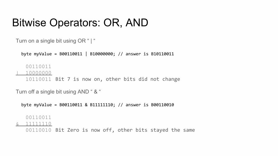
Arduino Pins vs AVR Ports/Pins
Arduino pins have numbers such as D0 to D13, A1 to A5 for the Uno.
AVR uses a different numbering system. Pins are grouped together into Ports and each Port has a different letter. Each Port can have up to 8 pins, each pin having a number.Example: PD0 = Port D, Pin 0
Different AVR chips have different features, so the AVR Port and Pin numbering changes for different chips. Arduino tries to standardize some of these basic features.
● Arduino Uno uses the Atmega328p AVR chip. The Serial RX function is on AVR pin PD0 which Arduino calls pin D0.
● Arduino Mega uses the Atmega2560 AVR chip. The Serial RX function is on AVR pin PE0 which Arduino calls pin D0.
Google search for “Arduino Uno pinout” and you can find great images showing the pin mappings for different types of Arduinos.

Direct Port AccessArduino functions digitalRead() and digitalWrite() are robust for beginners but quite slow. These Arduino functions have the added step of translating the Arduino pin number to the AVR pin number and also double-check a number of other things for issues. Skipping this gets the job done 40-80x faster.
Turn on Port D Pin 0:
PORTD = B00000001; // Turns on PD0 and turns off PD1 through PD7.
PORTD = PORTD | B00000001; // Turns on PD0. PD1 through PD7 stay the same.
Turn off Port B Pins 1, 3, and 5:
PORTB = PORTB & B11010101; // Turns off PB1,PB3,PB5. Others don’t change.
If your project requires several pins to be turned on or off at the same time, Direct Port Access allows that, while the Arduino function digitalWrite() can’t help.

Direct Port AccessDirect port access is great if you want to expand your IO using a multiplexer. Wire up the MUX’s channel select pins to an AVR port and the channel can be selected very quickly.
The “4067” chip is a 16 channel analog mutiplexer. 4 control lines are used to select which channel is connected.
void SetMux(byte channel){ PORTB &= 0B11110000; // clear bits PB0 to PB3 PORTB |= channel; // write ch to bits PB0 to PB3}

Direct Port AccessThe PINx registers can be used to read 8 digital inputs at once, replacing digitalRead().
Whenever a PINx register is read, all pins of that port are read at the same time, even if they are set as an output. If you only want to read a single pin, discard the values you don’t care about.
myValue = PIND; // Reads PortD pins 0 through 7
myValue = PIND & B00000001; // Reads PortD D0 through D7, D1 through D7 are discarded
myValue = (PINB & B00001000) >> 3; // Reads PortB pin 3.

Direct Port AccessDon’t forget to set the direction of each Pin. Arduino does this using the pinMode() function. For AVR, directly accessing the DDRn register can speed things up.
Set Port D Pin 0 as an output:
DDRD = DDRD | B00000001; // Set pin 0 as output, other pins unaffected
Set PortB Pins 1, 3, and 5 as input:
DDRB = DDRB & B11010101; // Sets pins 1,3,5 as inputs, other pins unaffected
If a particular pin in your project is changing direction of pins very often, then using the DDRn registers can speed up your program.
If a pin’s direction is only setup once at the beginning of your program and never changes again, then it’s probably better to use the Arduino pinMode() function.

Timer/Counter ModulesMultipurpose hardware inside the AVR that can perform a variety of functions such as:
● Generating PWM signals: Frequency, Duty Cycle - analogWrite()● Keeping track of time - delay(), millis()● Generating interrupts to run a function at a specific time interval● Counting pulses
Uno has 3 Timer/Counters
Mega has 6 Timer/Counters
Each Timer/Counter is controlled using a number ofdifferent registers such as:Settings: TCCRnx, OCRnx, TIMSKnCounter: TCNTnOutputs: OCnx, TIFRn
Counters can be 8 bit (0-255) or 16 bit (0-65535)

Timer/Counter Pin MappingEach Timer/Counter module is connected to specific pins.
For Atmega328p / Arduino Uno: For Atmega2560 / Arduino Mega:
Good references from Arduino:https://www.arduino.cc/en/Tutorial/SecretsOfArduinoPWMhttps://playground.arduino.cc/Main/TimerPWMCheatsheet
Timer Arduino Pins AVR Pins
0 13, 4 PB7,PG5
1 12, 11 PB6,PB5
2 10, 9 PB4,PH6
3 5, 3, 2 PE3,PE5,PE4
4 8, 7, 6 PH5,PH4,PH3
Timer Arduino Pins AVR Pins
0 6, 5 PD6,PD5
1 9, 10 PB1,PB2
2 11, 3 PB3,PD3

PWM ModesAVR Counters have different modes of counting. This results in different PWM signals being generated.
Fast PWM only counts up, and rolls-over at the top creating a sawtooth wave. The front edges of each PWM pulse are equally spaced.
Phase Correct PWM counts up and down creating a triangle wave. The middle of each PWM pulse is equally spaced.
For applications like blinky LEDs, servos, and motor drivers, the choice of PWM mode generally doesn’t matter other than it cuts the PWM frequency in half.
By default, Arduino operates all the Timers in Fast PWM mode.
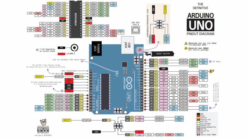
Clock SourceEvery counter has its own clock. The counter increments or decrements once for every tick of the “clock”. The clock source may be the main system clock (16MHz crystal) or an external clock source coming from a pin.
The clock source can be changed using the Clock Select bits of the TCCRnB register. These vary slightly from one Timer to another. Not all Timers are capable of having an external clock source. Different timers have different prescaler options available.
ATmega328p Timer0 Clock Source Options:
OffSame as XTAL (16 MHz)⅛ of 16 MHz = 2 MHz1/64 of 16 MHz = 250 kHz1/256 of 16 MHz = 62.5 kHz1/1024 of 16 MHz = 15.6 kHzPin T0 = PD4 = Arduino D4

Change PWM Frequency using PrescalerWhen using the internal clock source, the Timer/Counter clock is equal to the system clock (16 MHz) divided by a selected Prescaler value.
Every tick of the Timer’s clock increments the Counter by 1 until it reaches its size limit (256 for 8-bit counter)
PWM Frequency = System Clock / Prescaler / Counter Size = 16 MHz / 64 / 256 = 976.56 Hz
Bits 0 to 2 of the TCCRnB Register set the Prescaler factor
TCCR0B = TCCR0B & B11111000 | B00000011; // set timer 0 prescaler to 64 for 976.56 Hz
Setting prescaler to 1, Timer Clock = System Clock. PWM Frequency = 16 MHz / 1 / 256 = 62.5 kHz
TCCR0B = TCCR0B & B11111000 | B00000001; // set timer 0 prescaler to 1 for 62500 Hz
Prescalers options are defined in the datasheet and allow coarse adjustment of the frequency.
Not all Timers have the same prescaler options available, check datasheet for details.

Set Prescalers - ATMEGA328p (Uno,Nano)//------------------------------ Set PWM frequency for D5 & D6 using Timer0 ------------------------------
TCCR0B = TCCR0B & B11111000 | B00000001; // set timer 0 divisor to 1 for PWM frequency of 62500.00 Hz
TCCR0B = TCCR0B & B11111000 | B00000010; // set timer 0 divisor to 8 for PWM frequency of 7812.50 Hz
TCCR0B = TCCR0B & B11111000 | B00000011; // set timer 0 divisor to 64 for PWM frequency of 976.56 Hz Default
TCCR0B = TCCR0B & B11111000 | B00000100; // set timer 0 divisor to 256 for PWM frequency of 244.14 Hz
TCCR0B = TCCR0B & B11111000 | B00000101; // set timer 0 divisor to 1024 for PWM frequency of 61.04 Hz
//------------------------------ Set PWM frequency for D9 & D10 using Timer1 ------------------------------
TCCR1B = TCCR1B & B11111000 | B00000001; // set timer 1 divisor to 1 for PWM frequency of 31372.55 Hz
TCCR1B = TCCR1B & B11111000 | B00000010; // set timer 1 divisor to 8 for PWM frequency of 3921.16 Hz
TCCR1B = TCCR1B & B11111000 | B00000011; // set timer 1 divisor to 64 for PWM frequency of 490.20 Hz Default
TCCR1B = TCCR1B & B11111000 | B00000100; // set timer 1 divisor to 256 for PWM frequency of 122.55 Hz
TCCR1B = TCCR1B & B11111000 | B00000101; // set timer 1 divisor to 1024 for PWM frequency of 30.64 Hz
//------------------------------ Set PWM frequency for D3 & D11 using Timer 2 ------------------------------
TCCR2B = TCCR2B & B11111000 | B00000001; // set timer 2 divisor to 1 for PWM frequency of 31372.55 Hz
TCCR2B = TCCR2B & B11111000 | B00000010; // set timer 2 divisor to 8 for PWM frequency of 3921.16 Hz
TCCR2B = TCCR2B & B11111000 | B00000011; // set timer 2 divisor to 32 for PWM frequency of 980.39 Hz
TCCR2B = TCCR2B & B11111000 | B00000100; // set timer 2 divisor to 64 for PWM frequency of 490.20 Hz Default
TCCR2B = TCCR2B & B11111000 | B00000101; // set timer 2 divisor to 128 for PWM frequency of 245.10 Hz
TCCR2B = TCCR2B & B11111000 | B00000110; // set timer 2 divisor to 256 for PWM frequency of 122.55 Hz
TCCR2B = TCCR2B & B11111000 | B00000111; // set timer 2 divisor to 1024 for PWM frequency of 30.64 Hz

Set Prescalers - ATMEGA2560 (Mega)//------------------------------ Set PWM frequency for D4 & D13 ------------------------------
TCCR0B = TCCR0B & B11111000 | B00000001; // set timer 0 divisor to 1 for PWM frequency of 62500.00 Hz
TCCR0B = TCCR0B & B11111000 | B00000010; // set timer 0 divisor to 8 for PWM frequency of 7812.50 Hz
TCCR0B = TCCR0B & B11111000 | B00000011; // set timer 0 divisor to 64 for PWM frequency of 976.56 Hz Default
TCCR0B = TCCR0B & B11111000 | B00000100; // set timer 0 divisor to 256 for PWM frequency of 244.14 Hz
TCCR0B = TCCR0B & B11111000 | B00000101; // set timer 0 divisor to 1024 for PWM frequency of 61.04 Hz
//------------------------------ Set PWM frequency for D11 & D12 -----------------------------
TCCR1B = TCCR1B & B11111000 | B00000001; // set timer 1 divisor to 1 for PWM frequency of 31372.55 Hz
TCCR1B = TCCR1B & B11111000 | B00000010; // set timer 1 divisor to 8 for PWM frequency of 3921.16 Hz
TCCR1B = TCCR1B & B11111000 | B00000011; // set timer 1 divisor to 64 for PWM frequency of 490.20 Hz Default
TCCR1B = TCCR1B & B11111000 | B00000100; // set timer 1 divisor to 256 for PWM frequency of 122.55 Hz
TCCR1B = TCCR1B & B11111000 | B00000101; // set timer 1 divisor to 1024 for PWM frequency of 30.64 Hz
//------------------------------ Set PWM frequency for D9 & D10 ------------------------------
TCCR2B = TCCR2B & B11111000 | B00000001; // set timer 2 divisor to 1 for PWM frequency of 31372.55 Hz
TCCR2B = TCCR2B & B11111000 | B00000010; // set timer 2 divisor to 8 for PWM frequency of 3921.16 Hz
TCCR2B = TCCR2B & B11111000 | B00000011; // set timer 2 divisor to 32 for PWM frequency of 980.39 Hz
TCCR2B = TCCR2B & B11111000 | B00000100; // set timer 2 divisor to 64 for PWM frequency of 490.20 Hz Default
TCCR2B = TCCR2B & B11111000 | B00000101; // set timer 2 divisor to 128 for PWM frequency of 245.10 Hz
TCCR2B = TCCR2B & B11111000 | B00000110; // set timer 2 divisor to 256 for PWM frequency of 122.55 Hz
TCCR2B = TCCR2B & B11111000 | B00000111; // set timer 2 divisor to 1024 for PWM frequency of 30.64 Hz

Set Prescalers - ATMEGA2560 (Mega)//------------------------------ Set PWM frequency for D2, D3 & D5 ---------------------------
TCCR3B = TCCR3B & B11111000 | B00000001; // set timer 3 divisor to 1 for PWM frequency of 31372.55 Hz
TCCR3B = TCCR3B & B11111000 | B00000010; // set timer 3 divisor to 8 for PWM frequency of 3921.16 Hz
TCCR3B = TCCR3B & B11111000 | B00000011; // set timer 3 divisor to 64 for PWM frequency of 490.20 Hz Default
TCCR3B = TCCR3B & B11111000 | B00000100; // set timer 3 divisor to 256 for PWM frequency of 122.55 Hz
TCCR3B = TCCR3B & B11111000 | B00000101; // set timer 3 divisor to 1024 for PWM frequency of 30.64 Hz
//------------------------------- Set PWM frequency for D6, D7 & D8 ---------------------------
TCCR4B = TCCR4B & B11111000 | B00000001; // set timer 4 divisor to 1 for PWM frequency of 31372.55 Hz
TCCR4B = TCCR4B & B11111000 | B00000010; // set timer 4 divisor to 8 for PWM frequency of 3921.16 Hz
TCCR4B = TCCR4B & B11111000 | B00000011; // set timer 4 divisor to 64 for PWM frequency of 490.20 Hz Default
TCCR4B = TCCR4B & B11111000 | B00000100; // set timer 4 divisor to 256 for PWM frequency of 122.55 Hz
TCCR4B = TCCR4B & B11111000 | B00000101; // set timer 4 divisor to 1024 for PWM frequency of 30.64 Hz
//------------------------------- Set PWM frequency for D44, D45 & D46 ------------------------
TCCR5B = TCCR5B & B11111000 | B00000001; // set timer 5 divisor to 1 for PWM frequency of 31372.55 Hz
TCCR5B = TCCR5B & B11111000 | B00000010; // set timer 5 divisor to 8 for PWM frequency of 3921.16 Hz
TCCR5B = TCCR5B & B11111000 | B00000011; // set timer 5 divisor to 64 for PWM frequency of 490.20 Hz Default
TCCR5B = TCCR5B & B11111000 | B00000100; // set timer 5 divisor to 256 for PWM frequency of 122.55 Hz
TCCR5B = TCCR5B & B11111000 | B00000101; // set timer 5 divisor to 1024 for PWM frequency of 30.64 Hz

PWM Frequency Fine TuningThe Arduino Tone() library allows you to choose an exact frequency, but the duty cycle is fixed at 50%.
Some Timers allow precise control of both Frequency and Duty Cycle. ● Atmega328p: Timer 1 using Uno/Nano pins 9 (OC1A) and 10 (OC1B).● Atmega2560: Timers 1; 3; 4; 5. Mega pins 11,12; 2,3,5; 6,7,8; 44,45,46; respectively
These are all 16-bit Timer/Counters - they count from 0 up to 65535 (216 - 1)
In Waveform Generation Mode 10, the TOP of the counter is no longer 65535, it is whatever you set it to using register ICRx. Changing the value in ICRx allows a specific frequency to be dialed in.
The OCRnx registers are still used to set the duty cycle, but must be less than the value of ICRx

Waveform Generation ModesWGM options vary for different timers.
16 bit timers like Timer 1 on the ATmega328p (Arduino Uno) and Timers 1, 3 and 4 on the Mega2560 offer many options.
Check the datasheet for your AVR chip to see what options are available for each Timer.

Timer1 Example Code - 20 kHzvoid setup() { // Configure Timer 1 for PWM @ Alternate Frequency TCCR1A = B10100010; // Set WGM to Mode 10 (Phase Correct PWM), Set COM1A1 and COM1B1 (Non-Inverted PWM on Ch A and B) TCCR1B = B00010001; // Set WGM to Mode 10 (Phase Correct PWM), Set CS10 (Prescaler = 1) ICR1 = 400; // Freq = System Clock / Prescaler / Counter TOP / 2 = 16 MHz / 1 / 400 / 2 = 20kHz TCNT1 = 0; // reset counter to 0
// Set the PWM pins as output. pinMode( 9, OUTPUT); pinMode(10, OUTPUT);}
void loop() { myAnalogWrite( 9, 320); // 320/400 = 80% duty cycle myAnalogWrite(10, 80); // 80/400 = 20% duty cycle}
void myAnalogWrite(int pin, int value) { // Sets the duty cycle for pins 9 and 10 if (pin == 9) OCR1A = value; If (pin == 10) OCR1B = value;}
Take a look a the Arduino Playground library for Timer1: https://playground.arduino.cc/Code/Timer1

Complimentary PWMSome applications call for two PWM pins to have the same frequency and duty cycle with one pin inverted.
This can be useful for driving an H-Bridge circuit connected to a motor, speaker, etc.
The COMnx[1:0] bits in the TCCRnA register can be used to set the PWM pin output to normal or inverted mode
// Set TCCR1A bit 6 (COM1A0) to 1 and bit 7 (COM1A1) to 1 so that OC1A (Arduino Pin 9) is invertedTCCR1A = (TCCR1A & 0b00111111) | 0b11000000;
// Set TCCR1A bit 4 COM1B0) to 0 and bit 5 (COM1B1) to 1 so that OC2A (Arduino Pin 10) is non-invertedTCCR1A = (TCCR1A & 0b11001111) | 0b00100000;
TCCR1B = (TCCR1B & 0b11111000) | 0b00000001; // Set the prescalerTCCR1A = (TCCR1A & 0b11111100) | 0b00000010; // Set the PWM Mode, can use Phase-Correct PWM or Fast-PWM ModeTCCR1B = (TCCR1B & 0b11100111) | 0b00010000; // Set the PWM Mode, can use Phase-Correct PWM or Fast-PWM ModeICR1 = 400; // PWM Mode is set to Mode 10, so we use ICR1 registers to set the frequency. 16 MHz / 1 / 400 / 2 = 20kHzOCR1A = 300; // Set the duty cycle for OC1A (Pin 9) to a value between 0 and 400OCR1B = OCR1A; // Set the duty cycle for OC1B (Pin 10) to be the same as Pin 9

Timer LimitationsTimers are a powerful but limited resource. It’s possible that two Libraries try to use a single timer - one or both will have problems. When using a library, find out if it uses any Timers.
● The millis() and delay() functions use Timer0. If Timer0 is changed from the default 976.56 Hz, then millis() and delay() will not do what you expect them to. If you change the WGM of Timer0, calling either function can hang your program.
● The servo() library uses Timer1 and disables PWM functionality on the associated PWM pins. If using Mega2560 and >24 servos, Timers 3 and 4 may also be affected.
○ https://www.arduino.cc/en/Reference/servo
● The tone() library uses Timers. It starts with Timer2 but can generate multiple tones by taking over several timers.
○ https://www.arduino.cc/reference/en/language/functions/advanced-io/tone/○ https://github.com/bhagman/Tone#ugly-details

Faster Analog to Digital Conversion (ADC)The ADC module has a clock source that is connected to the 16 MHz system clock by a prescaler. Changing the value of the prescaler changes how much time it takes to complete an A-D conversion
Per the manufacturer’s recommendation, Arduino libraries set the ADC prescaler to 128 so the ADC clock runs at 16 MHz / 128 = 125 kHz. One ADC conversion cycle takes 13 ticks of the ADC clock.
ADC Sample Rate = System Clock / ADC Prescaler / 13 = 16 MHz / 128 / 13 = 9615 Hz default sample rate ADC Sample Time = 1 / Sample Rate = 104 micro-seconds
The default prescaler of 128 used by Arduino maximizes the accuracy of the ADC but is the slowest available option.
Faster conversions can be achieved by reducing the prescaler. Setting the prescaler to 64 doubles the conversion speed and is quite safe for most applications.
// In the setup() function... ADCSRA = ADCSRA & B11111000 | B00000110; // Set ADC prescaler to 64
Even faster conversion speeds are possible but there is a catch...

Analog Source ImpedanceThe ADC module uses a sample and hold capacitor that needs to be charged by the analog input. It takes time to charge this capacitor. Speeding up the ADC clock rate reduces the amount of time spent charging and can result in inaccurate readings.
Analog input sources with an impedance of 10k ohm or less are ideal.
For example, the popular QTR-8A line following sensor from Pololu has an output impedance of 47k ohm. This is above the 10k ohm recommended for best performance.
Pololu QTR-8A Line Sensor Output Circuit
The good news is that most robots don’t require 10-bit accuracy from every sensor. If you only need ~6 bits of accuracy, crank up the ADC clock to 1 MHz and don’t worry about it.

Even Faster Analog to Digital Conversion (ADC)There are two options for speeding up the ADC clock while maintaining quality of the readings // First, put this in your setup() function to set the prescaler ADCSRA = ADCSRA & B11111000 | B00000100; // Set ADC prescaler to 16 - ADC clock is 1 MHz
Option 1: Call analogRead() twice, disregard first reading // Whenever reading an analog voltage in your program, read twice like this... analogRead(sensorPin); // don’t do anything with the first reading int mySensor = analogRead(sensorPin); // keep the second reading
Option 2: Replace analogRead() with your own custom function with extra delay for charging capacitor int myAnalogRead(uint8_t pin){ #if defined(ADCSRB) && defined(MUX5) ADCSRB = (ADCSRB & ~(1 << MUX5)) | (((pin >> 3) & 0x01) << MUX5); // This is for the Mega, A8 to A15 #endif ADMUX = (0x01 << 6) | (pin & 0x07); delayMicroseconds(10); // Extra Delay Here. Test to figure out how little you can get away with. sbi(ADCSRA, ADSC); while (bit_is_set(ADCSRA, ADSC)); uint8_t low = ADCL; return (ADCH << 8) | low; }

Measure VCC using internal 1.1V ReferenceAtmega328p and Atmega2560 have an internal 1.1V reference that can be read by the ADC. When powering the AVR directly from a 3.3 to 5V battery, we can use this reference voltage to back-calculate the battery’s voltage on VCC.
uint32_t readVcc() { // Read 1.1V reference against AVcc // set the reference to Vcc and the measurement to the internal 1.1V reference ADMUX = _BV(REFS0) | _BV(MUX3) | _BV(MUX2) | _BV(MUX1); delay(4); // Wait for Vref to settle ADCSRA |= _BV(ADSC); // Start first conversion. First conversion is not saved. while (bit_is_set(ADCSRA,ADSC)); // wait for measurement to complete ADCSRA |= _BV(ADSC); // Start second conversion. while (bit_is_set(ADCSRA,ADSC)); // wait for measurement to complete uint8_t low = ADCL; // must read ADCL first - it then locks ADCH uint8_t high = ADCH; // unlocks both uint32_t result = (high<<8) | low; const float internalRef = 1.1; // The internal 1.1V ref is rated for +/- 10% accuracy. This can be manually calibrated for each AVR chip if more accuracy is needed. // Conversion Factor to Calculate Vcc (in mV); 1125300 = 1.1*1023*1000 const uint32_t scale_constant = internalRef * 1023 * 1000; result = scale_constant / result; // Calculate Vcc (in mV); 1125300 = 1.1*1023*1000 return result; // Vcc in millivolts}

Further Investigation
Inspect the Arduino’s user-friendly functions by searching your Arduino folder for the following files:
Default settings and timing functions: wiring.cDigital functions: wiring_digital.cAnalog functions: wiring_analog.c
Was this useful?
Potential Future Topics:Measuring how long code takes to run
Avoiding Division
Using I2C and/or Serial to communicate from one Arduino to another
Storing data in EEPROM
Low Power modes