Embed Size (px)
Citation preview

PROJECTOR-BASED THREE DIMENSIONAL GRAPHICS
by
Ramesh Raskar
A dissertation submitted to the faculty of the University of North Carolina at Chapel Hill in partial
fulfillment of the requirements for the degree of Doctor of Philosophy in the Department of Computer
Science.
Chapel Hill
2002
Approved by:
Co-Advisor: Henry Fuchs
Co-Advisor: Gregory Welch
Reader: Guido Gerig
Gary Bishop
Leonard McMillan

c© 2002
Ramesh Raskar
ALL RIGHTS RESERVED
ii

ABSTRACT
Ramesh Raskar
Projector-based Three Dimensional Graphics
(Under the direction of Henry Fuchs and Gregory Welch)
Light projectors can be arranged into electronic displays that offer large, bright, and high
resolution images. However, despite their unique characteristics, projectors have been treated like
any other two-dimensional display devices, e.g. CRT monitors or LCD panels, to create flat and
usually rectangular images. Even the growth of three dimensional computer graphics has followed
this limitation.
To improve and widen the range of applications of projectors, in this dissertation I present a
single unified geometric framework for projector-based graphics. It is based on the notion of the
projector as the dual of a camera. The geometric framework is based on (i) the analytical projection
model, (ii) the geometric representation of the display surface and (iii) the viewer location. The
framework can be used for practically all the projector-based applications. For classic projector-
based systems, such as tiled displays or immersive panoramic displays, the framework provides a
fundamentally different approach that allows greater freedom and flexibility. In addition, it enables a
new class of projector-based visualization methods.
iii

ACKNOWLEDGMENTS
Thanks to
My co-advisors Henry Fuchs and Greg Welch for their guidance and encouragement, for introducingme to many of the topics in this dissertation, and for their support and patience through a difficultyear after my thesis defense
My committee members Gary Bishop, Guido Gerig and Leonard McMillan for many wonderfuldiscussions and suggestions
Herman Towles and The UNC STC group for providing an excellent research environment
Mike Brown, Matt Cutts and Kok-lim Low who worked closely with me to build many researchprototypes
Gopi M., for his friendship, and for many stimulating conversations
John ’Spike’ Hughes (Brown U.), Brent Seales (U. of Kentucky) and Peter Schroeder (CalTech) forexcellent suggestions
DARPA, NSF, NTII, Link Foundation and Intel for funding my research
Linda Welch, George Spindler and Marty Spindler for the wooden Taj Mahal model used in ShaderLamps demonstration
Andrei State for his beautiful sketches
Joe Marks (MERL-Research Director) for giving me the freedom to complete the dissertation atMERL
Many fellow grad students with whom I spent so much time, especially Deepak BandyopadhyaySumedh Barde, Wei-Chao Chen, Gentaro Hirota, Adam Lake, Shankar Krishnan, Aditi Majumder,Ajit Mascarhenas, Atsuko Negishi, Amol Pattekar, Voicu Popescu, Sunay Tripathi, Ruigang Yang,and many others
The staff of the UNC computer science department, for helping me in innumerable ways and forbeing a pleasure to work with
My parents for their love and for being supportive of whatever I wanted to do in life, my brotherPrakash for his motivating spirit and guidance, my sister Nanda for her selfless dedication and heremphasis on education, my sister Neeta for her humor and good cheer, and Rebecca for all she is.
iv

TABLE OF CONTENTS
LIST OF FIGURES . . . . . . . . . . . . . . . . . . . . . . . . . . . . . . . . . . . . . . . . x
CHAPTER 1: Introduction . . . . . . . . . . . . . . . . . . . . . . . . . . . . . . . . . . 1
1.1 The Problem and Approach . . . . . . . . . . . . . . . . . . . . . . . . . . . . . . . 1
1.2 Computer Graphics for Projectors . . . . . . . . . . . . . . . . . . . . . . . . . . . 3
1.3 Thesis statement . . . . . . . . . . . . . . . . . . . . . . . . . . . . . . . . . . . . . 5
1.4 Outline . . . . . . . . . . . . . . . . . . . . . . . . . . . . . . . . . . . . . . . . . 5
1.4.1 The Past: New Approach for Classic Applications . . . . . . . . . . . . . . . 6
1.4.2 The Present: Enabling Novel Applications . . . . . . . . . . . . . . . . . . . 6
1.4.3 The Future: New Territories . . . . . . . . . . . . . . . . . . . . . . . . . . 7
1.5 Contributions . . . . . . . . . . . . . . . . . . . . . . . . . . . . . . . . . . . . . . 7
1.6 The Story . . . . . . . . . . . . . . . . . . . . . . . . . . . . . . . . . . . . . . . . 8
1.7 Summary . . . . . . . . . . . . . . . . . . . . . . . . . . . . . . . . . . . . . . . . 9
CHAPTER 2: Background . . . . . . . . . . . . . . . . . . . . . . . . . . . . . . . . . . 10
2.1 Projector-based environments . . . . . . . . . . . . . . . . . . . . . . . . . . . . . . 10
2.1.1 Panoramic environments . . . . . . . . . . . . . . . . . . . . . . . . . . . . 11
2.1.2 Tiled planar displays . . . . . . . . . . . . . . . . . . . . . . . . . . . . . . 11
2.1.3 Illumination of objects . . . . . . . . . . . . . . . . . . . . . . . . . . . . . 12
2.2 Image-based rendering . . . . . . . . . . . . . . . . . . . . . . . . . . . . . . . . . 13
2.2.1 Panoramic mosaics of photographs . . . . . . . . . . . . . . . . . . . . . . 14
2.2.2 Reprojection . . . . . . . . . . . . . . . . . . . . . . . . . . . . . . . . . . 15
2.2.3 Blending . . . . . . . . . . . . . . . . . . . . . . . . . . . . . . . . . . . . 15
2.3 Summary . . . . . . . . . . . . . . . . . . . . . . . . . . . . . . . . . . . . . . . . 16
CHAPTER 3: Framework for Projector-Based Graphics . . . . . . . . . . . . . . . . . 17
3.1 Conceptual Framework . . . . . . . . . . . . . . . . . . . . . . . . . . . . . . . . . 18
v

3.1.1 Geometric Relationship . . . . . . . . . . . . . . . . . . . . . . . . . . . . 18
3.1.2 Geometric Components . . . . . . . . . . . . . . . . . . . . . . . . . . . . . 20
Projector Model . . . . . . . . . . . . . . . . . . . . . . . . . . . . . . . 20
Display Portal . . . . . . . . . . . . . . . . . . . . . . . . . . . . . . . . 22
Use Location . . . . . . . . . . . . . . . . . . . . . . . . . . . . . . . . . 22
3.2 Rendering Framework . . . . . . . . . . . . . . . . . . . . . . . . . . . . . . . . . 22
3.2.1 Rendering components . . . . . . . . . . . . . . . . . . . . . . . . . . . . . 23
3.2.2 Rendering strategy . . . . . . . . . . . . . . . . . . . . . . . . . . . . . . . 23
3.2.3 Example 1: Non-planar surface . . . . . . . . . . . . . . . . . . . . . . . . 24
3.2.4 Example 2: Planar surface . . . . . . . . . . . . . . . . . . . . . . . . . . . 26
3.2.5 Example 3: A Self Correcting Projector . . . . . . . . . . . . . . . . . . . . 27
3.3 Calibration Goals . . . . . . . . . . . . . . . . . . . . . . . . . . . . . . . . . . . . 28
3.3.1 Parameter Estimation . . . . . . . . . . . . . . . . . . . . . . . . . . . . . 28
3.3.2 Geometric Registration . . . . . . . . . . . . . . . . . . . . . . . . . . . . . 29
3.3.3 Intensity Normalization . . . . . . . . . . . . . . . . . . . . . . . . . . . . . 30
3.4 Display Environments and Applications . . . . . . . . . . . . . . . . . . . . . . . . 32
3.5 Summary . . . . . . . . . . . . . . . . . . . . . . . . . . . . . . . . . . . . . . . . 33
CHAPTER 4: A New Approach for Classic Applications . . . . . . . . . . . . . . . . . . 34
4.1 Generalized Panoramic Displays . . . . . . . . . . . . . . . . . . . . . . . . . . . . 35
4.1.1 Single projector display . . . . . . . . . . . . . . . . . . . . . . . . . . . . 36
Camera Calibration . . . . . . . . . . . . . . . . . . . . . . . . . . . . . 37
Display Surface Estimation . . . . . . . . . . . . . . . . . . . . . . . . . 38
Projector Calibration . . . . . . . . . . . . . . . . . . . . . . . . . . . . . 38
2-Pass Rendering Algorithm . . . . . . . . . . . . . . . . . . . . . . . . . 38
4.1.2 Multiple Projector Display . . . . . . . . . . . . . . . . . . . . . . . . . . . 39
Surface Mesh Registration . . . . . . . . . . . . . . . . . . . . . . . . . . 39
Projector Registration . . . . . . . . . . . . . . . . . . . . . . . . . . . . 40
Projector Overlap Intensity Blending . . . . . . . . . . . . . . . . . . . . 40
Tracked Viewer Registration . . . . . . . . . . . . . . . . . . . . . . . . . 42
4.1.3 Compensation of errors . . . . . . . . . . . . . . . . . . . . . . . . . . . . 42
Display Surface Errors . . . . . . . . . . . . . . . . . . . . . . . . . . . . 44
vi
Projector Calibration Error . . . . . . . . . . . . . . . . . . . . . . . . . 44
Geometric Error Compensation . . . . . . . . . . . . . . . . . . . . . . . 45
Surface Mesh Unification . . . . . . . . . . . . . . . . . . . . . . . . . . 45
Post-rendering Warp . . . . . . . . . . . . . . . . . . . . . . . . . . . . . 49
4.1.4 Implementation . . . . . . . . . . . . . . . . . . . . . . . . . . . . . . . . . 50
4.1.5 Special Cases . . . . . . . . . . . . . . . . . . . . . . . . . . . . . . . . . . 51
Static User . . . . . . . . . . . . . . . . . . . . . . . . . . . . . . . . . . 51
4.2 Planar Displays . . . . . . . . . . . . . . . . . . . . . . . . . . . . . . . . . . . . . 52
Previous Approach . . . . . . . . . . . . . . . . . . . . . . . . . . . . . . 53
4.2.1 Single Projector . . . . . . . . . . . . . . . . . . . . . . . . . . . . . . . . 54
Orthogonal Projection . . . . . . . . . . . . . . . . . . . . . . . . . . . . 55
Collineation . . . . . . . . . . . . . . . . . . . . . . . . . . . . . . . . . 56
4.2.2 Single-pass Rendering . . . . . . . . . . . . . . . . . . . . . . . . . . . . . 56
4.2.3 Visibility using depth buffer . . . . . . . . . . . . . . . . . . . . . . . . . . 58
Problems with depth buffer . . . . . . . . . . . . . . . . . . . . . . . . . 58
Approximation of depth buffer . . . . . . . . . . . . . . . . . . . . . . . 59
4.2.4 Multiple projectors . . . . . . . . . . . . . . . . . . . . . . . . . . . . . . . 60
4.2.5 Implementation . . . . . . . . . . . . . . . . . . . . . . . . . . . . . . . . . 61
Summary of Techniques . . . . . . . . . . . . . . . . . . . . . . . . . . . 63
4.2.6 Applications . . . . . . . . . . . . . . . . . . . . . . . . . . . . . . . . . . 63
4.2.7 Issues . . . . . . . . . . . . . . . . . . . . . . . . . . . . . . . . . . . . . . 64
4.2.8 Discussion . . . . . . . . . . . . . . . . . . . . . . . . . . . . . . . . . . . 65
4.3 Summary . . . . . . . . . . . . . . . . . . . . . . . . . . . . . . . . . . . . . . . . 66
CHAPTER 5: Novel Applications . . . . . . . . . . . . . . . . . . . . . . . . . . . . . . . 67
5.1 Spatially Augmented Reality . . . . . . . . . . . . . . . . . . . . . . . . . . . . . . 68
5.1.1 Comparison with Spatially Immersive Displays . . . . . . . . . . . . . . . . 68
5.1.2 Comparison with Head Mounted Augmented Reality Display . . . . . . . . . 69
5.1.3 Applications . . . . . . . . . . . . . . . . . . . . . . . . . . . . . . . . . . 70
5.2 Shader Lamps . . . . . . . . . . . . . . . . . . . . . . . . . . . . . . . . . . . . . . 71
5.2.1 Motivation . . . . . . . . . . . . . . . . . . . . . . . . . . . . . . . . . . . 73
Graphics in the World . . . . . . . . . . . . . . . . . . . . . . . . . . . . 73
vii

Stimulation and Communication of Ideas . . . . . . . . . . . . . . . . . 73
Image-Based Illumination . . . . . . . . . . . . . . . . . . . . . . . . . . 74
5.2.2 What is New . . . . . . . . . . . . . . . . . . . . . . . . . . . . . . . . . . 75
5.2.3 Previous Work . . . . . . . . . . . . . . . . . . . . . . . . . . . . . . . . . 75
Theater and entertainment . . . . . . . . . . . . . . . . . . . . . . . . . . 75
Tangible luminous interfaces . . . . . . . . . . . . . . . . . . . . . . . . 76
Modeling and rendering architecture from photographs . . . . . . . . . . 77
5.2.4 The Rendering Process . . . . . . . . . . . . . . . . . . . . . . . . . . . . . 77
Secondary Scattering . . . . . . . . . . . . . . . . . . . . . . . . . . . . 80
Illumination of All Visible Surfaces . . . . . . . . . . . . . . . . . . . . . 81
5.2.5 Methods . . . . . . . . . . . . . . . . . . . . . . . . . . . . . . . . . . . . . 81
Authoring and Alignment . . . . . . . . . . . . . . . . . . . . . . . . . . 82
Intensity Correction . . . . . . . . . . . . . . . . . . . . . . . . . . . . . 83
Occlusions and Overlaps . . . . . . . . . . . . . . . . . . . . . . . . . . 83
5.2.6 Advantages . . . . . . . . . . . . . . . . . . . . . . . . . . . . . . . . . . . 87
5.2.7 Problems . . . . . . . . . . . . . . . . . . . . . . . . . . . . . . . . . . . . 89
5.2.8 Implementation . . . . . . . . . . . . . . . . . . . . . . . . . . . . . . . . . 89
Appendix . . . . . . . . . . . . . . . . . . . . . . . . . . . . . . . . . . 91
5.3 Summary . . . . . . . . . . . . . . . . . . . . . . . . . . . . . . . . . . . . . . . . 91
CHAPTER 6: New Territories . . . . . . . . . . . . . . . . . . . . . . . . . . . . . . . . 92
6.1 Static Illumination . . . . . . . . . . . . . . . . . . . . . . . . . . . . . . . . . . . 92
Object Textures . . . . . . . . . . . . . . . . . . . . . . . . . . . . . . . 92
Interactive surface probing . . . . . . . . . . . . . . . . . . . . . . . . . . 93
Inverse Global Illumination . . . . . . . . . . . . . . . . . . . . . . . . . 93
Rendering Libraries . . . . . . . . . . . . . . . . . . . . . . . . . . . . . 93
6.2 Tracking, Detection and Control . . . . . . . . . . . . . . . . . . . . . . . . . . . . 94
6.2.1 User tracking . . . . . . . . . . . . . . . . . . . . . . . . . . . . . . . . . . 95
6.2.2 Projector tracking . . . . . . . . . . . . . . . . . . . . . . . . . . . . . . . 96
Changing Pose . . . . . . . . . . . . . . . . . . . . . . . . . . . . . . . . 96
Changing Internal Parameters . . . . . . . . . . . . . . . . . . . . . . . . 97
6.2.3 Illuminating dynamically moving objects . . . . . . . . . . . . . . . . . . . 97
viii

Smart building blocks . . . . . . . . . . . . . . . . . . . . . . . . . . . . 99
6.3 Vision-based input . . . . . . . . . . . . . . . . . . . . . . . . . . . . . . . . . . . 99
Self calibration . . . . . . . . . . . . . . . . . . . . . . . . . . . . . . . . 99
Shadow Elimination . . . . . . . . . . . . . . . . . . . . . . . . . . . . . 100
6.4 Summary . . . . . . . . . . . . . . . . . . . . . . . . . . . . . . . . . . . . . . . . 100
CHAPTER 7: Conclusion . . . . . . . . . . . . . . . . . . . . . . . . . . . . . . . . . . . 101
7.1 Synopsis . . . . . . . . . . . . . . . . . . . . . . . . . . . . . . . . . . . . . . . . . 101
7.1.1 Projector as the dual of a camera . . . . . . . . . . . . . . . . . . . . . . . 101
7.1.2 Past, Present and Future . . . . . . . . . . . . . . . . . . . . . . . . . . . . 102
7.1.3 Image-Based Illumination . . . . . . . . . . . . . . . . . . . . . . . . . . . 103
7.2 Projectors and 3D Computer Graphics . . . . . . . . . . . . . . . . . . . . . . . . . 103
7.2.1 Advantages . . . . . . . . . . . . . . . . . . . . . . . . . . . . . . . . . . . 103
7.2.2 Disadvantages . . . . . . . . . . . . . . . . . . . . . . . . . . . . . . . . . 104
7.3 Future Work . . . . . . . . . . . . . . . . . . . . . . . . . . . . . . . . . . . . . . . 104
Photometric Issues . . . . . . . . . . . . . . . . . . . . . . . . . . . . . . 104
Calibration . . . . . . . . . . . . . . . . . . . . . . . . . . . . . . . . . . 104
User Interface . . . . . . . . . . . . . . . . . . . . . . . . . . . . . . . . 105
Distributed Rendering . . . . . . . . . . . . . . . . . . . . . . . . . . . . 106
APPENDIX A: Depth of Field . . . . . . . . . . . . . . . . . . . . . . . . . . . . . . . . . 107
A.1 Plane and range of focus . . . . . . . . . . . . . . . . . . . . . . . . . . . . . . . . 107
A.2 Depth of field and lens aperture . . . . . . . . . . . . . . . . . . . . . . . . . . . . . 109
APPENDIX B: Depth Calculation after Collineation . . . . . . . . . . . . . . . . . . . . 111
B.1 Points along a line segment . . . . . . . . . . . . . . . . . . . . . . . . . . . . . . . 112
B.2 Verification of depth calculation . . . . . . . . . . . . . . . . . . . . . . . . . . . . 112
BIBLIOGRAPHY . . . . . . . . . . . . . . . . . . . . . . . . . . . . . . . . . . . . . . . . 114
ix

LIST OF FIGURES
1.1 Top: Panoramic photo-mosaic from multiple images. Bottom: How can we create apanoramic display using roughly aligned projectors ? . . . . . . . . . . . . . . . . . 2
1.2 Can we make the white clay vase (top) look like it is made up of marble, plastic(bottom left) or metal (bottom right)? . . . . . . . . . . . . . . . . . . . . . . . . . 3
1.3 Outline of the thesis. The new geometric framework leads to rendering andcalibration algorithms. They are used in various display applications. . . . . . . . . . 5
2.1 CAVE and ImmersaDesk . . . . . . . . . . . . . . . . . . . . . . . . . . . . . . . . 11
2.2 Layout for three projector Reality Room by Trimensions Inc. . . . . . . . . . . . . . 12
2.3 Illumination of large architecture, Son et Lumiere light show. . . . . . . . . . . . . . 12
3.1 Geometric Framework and its applications. . . . . . . . . . . . . . . . . . . . . . . 17
3.2 Rendering the image of virtual object under different projector display configurations. 18
3.3 Relationship between geometric components. . . . . . . . . . . . . . . . . . . . . . 19
3.4 Types of irregular display surfaces . . . . . . . . . . . . . . . . . . . . . . . . . . . 23
3.5 The Rendering Framework. . . . . . . . . . . . . . . . . . . . . . . . . . . . . . . . 25
3.6 Two-pass rendering for non-planar display surface involves forward and backwardmapping. . . . . . . . . . . . . . . . . . . . . . . . . . . . . . . . . . . . . . . . . 26
3.7 Rendering for planar surface. The pixels mT and mP are related by a homography. . 27
3.8 Given three angles of relative orientation, how should the input image be pre-warpedto display axis aligned rectangular image? . . . . . . . . . . . . . . . . . . . . . . . 28
3.9 Ideal case, accurate registration. Top two rows, choice (a): contribution from a singleprojector for each point. Rows 3 and 4, choice (b): equal contribution from each projector inthe overlap. Rows 5 and 6, choice (c): linear ramps in the overlap. Bottom row: Per pixeladdition of contributing weights, all methods result in same solution. . . . . . . . . . . . . 30
3.10 Choice (a): Contribution from a single projector at every point in overlap. Top three rowsshow result of mis-registration in case of projectors moving away from each other. Top row,projector moves to left. Second row, projector moves to right. Third row, resulting additionshows a dark gap. Bottom three rows show extra overlap results in a spiked region that istwice as bright. . . . . . . . . . . . . . . . . . . . . . . . . . . . . . . . . . . . . . . 30
x

3.11 Choice (b): Equal contribution from both projectors at every point in overlap. Top threerows show projector moving away from each other, resulting in a visible valley of loweredintensity. Bottom three rows show extra overlap results in a narrow brighter regions. . . . . 30
3.12 Choice (c): Linear ramps in overlap. Top three rows show projector moving away from eachother, resulting in a overlap region with overall slightly lower intensity. Bottom three rowsshow extra overlap results in slightly brighter overlap regions. . . . . . . . . . . . . . . . 30
3.13 The display continuum. . . . . . . . . . . . . . . . . . . . . . . . . . . . . . . . . . 32
4.1 (a) The display techniques allow for an wide range of configuration of roughlyaligned projectors and displays. (b) Example of arbitrary projector overlaps beforecalibration. (c) Viewer in the final display environment. . . . . . . . . . . . . . . . 35
4.2 Configuration for single projector. . . . . . . . . . . . . . . . . . . . . . . . . . . . 37
4.3 A panoramic image (100 degree FOV) of the panoramic five projector display system. 39
4.4 The top image shows the overlap position of three projectors. The bottom imagesshow the alpha masks created for projectors 1, 2, and 3 using feathering algorithm. . 42
4.5 3D points of the two display surfaces do not agree after registration with a rigidtransformation so we use weighted averaging to obtain geometric continuity acrossthe surfaces. Top row: Before and after mesh unification. Middle row: In flat land,before unification. Bottom left: Select corresponding points on the meshes and finda weighted average for smooth transition. Bottom right: Unified mesh. Note thatthe unified mesh is a convex combination of the component meshes but does notnecessarily eliminate the deviation from the original mesh. . . . . . . . . . . . . . . 46
4.6 (a) Error in estimation of a physical point M on the display surface and error inestimated projection matrix P ′
1 creates mis-registration. The reprojection error ism′′ − m. . . . . . . . . . . . . . . . . . . . . . . . . . . . . . . . . . . . . . . . . . 47
4.7 (a) Reprojection error, shown in red, for two overlapping projectors. (b) A virtualpoint for which the image is computed to be projected at M . (c) The physicalcorrespondence due to M and computational correspondence due to virtual pointV . The goal of post-rendering warp is to exploit the two known correspondences toachieve geometric registration. . . . . . . . . . . . . . . . . . . . . . . . . . . . . . 48
4.8 Left, Display environment with five projectors. Middle and Right, The images appearseamless and are updated as the user moves. . . . . . . . . . . . . . . . . . . . . . . 51
4.9 (a) Traditional projectors are orthogonal and create rectangular images (b) Obliqueprojectors create keystoned images. . . . . . . . . . . . . . . . . . . . . . . . . . . 53
4.10 For orthogonal projectors, a simple off-axis projection can be used. . . . . . . . . . . 54
4.11 Defining PT using axis aligned bounding rectangle S. . . . . . . . . . . . . . . . . . 55
xi

4.12 (a) First step using simple off-axis projection matrix PT (b) In the second step, warpusing collineation A. The modified projection matrix is APT . . . . . . . . . . . . . . 57
4.13 The plot shows depth buffer values along a scan line for points along constant depth.(a) Using PT (b) After collineation, A4×4PT , the depth values range beyond [−1, 1](c) With an approximation of depth-buffer, A′
4×4PT , traditional graphics pipeline canbe used to render perspectively correct images for a tracked moving user. . . . . . . 59
4.14 Collineation between overlapping projectors on planar display surface. . . . . . . . . 60
4.15 For a given plane of focus, projector can be treated as a pin-hole device. Thepictures here show experimental verification of linear perspective projection. Straightline segments in image plane appear straight on a planar display surface (top).Further, line segments projected by overlapping projectors can be aligned to sub-pixelaccuracy using homography (bottom left). Example of overlapping text in a warpedimage (bottom right). . . . . . . . . . . . . . . . . . . . . . . . . . . . . . . . . . . 64
4.16 Top row: Images displayed by oblique projector which created keystoned imageryand but corrected using collineation. Bottom row: Displayed image without and withintensity blending. . . . . . . . . . . . . . . . . . . . . . . . . . . . . . . . . . . . . 65
5.1 HMD-AR and SAR . . . . . . . . . . . . . . . . . . . . . . . . . . . . . . . . . . . 68
5.2 Spatially augmenting large environment (Kok-lim Low et al, 2001). (Top left) Virtualmodel; (Top right) Physical display environment constructed using Styrofoam blocks;(Bottom row) Augmented display. Note the view dependent nature of the display, theperspectively correct view through the hole in the wall and the windows. . . . . . . 70
5.3 The surface appearance of a neutral colored object is changed by ’painting’ it withprojected light. . . . . . . . . . . . . . . . . . . . . . . . . . . . . . . . . . . . . . 72
5.4 Underlying physical model of Taj Mahal and enhanced with shader lamps. . . . . . . 72
5.5 Concept of shader lamps. Physical textures (above) and shader lamp textures (below) 74
5.6 From the Walt Disney World ”Haunted Mansion,” still cells of animated facesprojected onto neutral busts (left), and Madame Leota’s head (right) . . . . . . . . . 76
5.7 The radiance at a point in the direction (right) The radiance as a result of illuminationfrom a projector lamp. By rearranging the parameters in the optical path, the two canbe made equal. . . . . . . . . . . . . . . . . . . . . . . . . . . . . . . . . . . . . . 78
5.8 (a) A green paper illuminated with white light (b) The white diffuse surface on theright is illuminated with green light. In this special case, the secondary scattering offthe white surface below is similar for both parts . . . . . . . . . . . . . . . . . . . . 80
xii

5.9 Intensity weights using feathering methods. The plots show the contribution ofprojectors A, B and B’ and the resultant accumulation A+B and A+B’ along thelit planar surface. Our technique, shown in (d), creates smooth weight transitions.(a) Simple intensity ramps on planar overlap create smooth transitions. (b) Weightscomputed using surface normals are no sufficient. (c) Occluders create sharptransitions (d) Our solution, which considers depth continuity, maintains the localsmoothness of intensity weights. . . . . . . . . . . . . . . . . . . . . . . . . . . . . 84
5.10 The vase is illuminated by two projectors.(a-b) Images rendered by first and secondprojectors. (c-d) The intensity weight images, including elimination of oblique parts,and correction for surface orientation and overlap (e-f) Final projected images afterintensity normalization. . . . . . . . . . . . . . . . . . . . . . . . . . . . . . . . . . 88
5.11 Top left: We used a 3D touch probe scanner to create a 3D model of the real object.Top right: The projectors are calibrated with respect to the model finding which pixels(the center of the cross) illuminate known 3D features. Bottom: The setup withprojectors and the illuminated TajMahal model. . . . . . . . . . . . . . . . . . . . . 90
6.1 Static and dynamic components of geometric framework . . . . . . . . . . . . . . . 94
6.2 A projector with camera and tilt sensors . . . . . . . . . . . . . . . . . . . . . . . . 96
6.3 Illumination of a tracked object . . . . . . . . . . . . . . . . . . . . . . . . . . . . . 98
A.1 Relationship between plane of focus and depth of field for a projector assuming thinlens model . . . . . . . . . . . . . . . . . . . . . . . . . . . . . . . . . . . . . . . . 108
B.1 Projection using off-axis projection matrix PT followed by a warp using collineationA′. . . . . . . . . . . . . . . . . . . . . . . . . . . . . . . . . . . . . . . . . . . . . 111
xiii

CHAPTER 1
Introduction
Light projectors as a display medium present unique benefits and challenges. They have long been
used to create rich and vivid images for presentations or to project movies for large audiences with
moving images and brilliant colors for entertainment. Thanks to the rapidly decreasing size and cost,
projectors are now increasingly being used for interactive computer graphics applications.
The research presented in this dissertation addresses the issues and opportunities in using three-
dimensional computer graphics techniques for projector-based displays. I describe a generalized
approach for projector-based three dimensional graphics. The approach allows one to re-formulate
the classic problems previously solved with disparate solutions. In addition, the generalized approach
enables a new class of graphics applications.
In this chapter, I first discuss the motivation for treating projector-based 3D graphics separate
from conventional 3D graphics. Then I introduce an enhanced geometric framework that provides a
basis for dealing with all projector-based rendering and calibration problems. Finally, I present the
outline for rest of this dissertation.
1.1 The Problem and Approach
Traditionally, a light projector is treated like any other two-dimensional display device such as a CRT
or a LCD screen to create flat and, usually, rectangular images. Note, however, that a light projector
can be treated as the dual of a camera, i.e. a projection device relating 3D space and an image. For
a camera, an analytical camera model such as the thin lens model or the pinhole projection model, is
a valuable abstraction that is used in various areas of computer vision, e.g. projective geometry and
calibration [Brown71, Newman73, LH81, Faugeras93]. In image-based rendering, the chosen camera

User
Projectors
Scre
en
Figure 1.1: Top: Panoramic photo-mosaic from multiple images. Bottom: How can we create apanoramic display using roughly aligned projectors ?
model is a key aspect in the creation of panoramic mosaics and the generation of novel views from
given source images [McMillan97]. If we treat a projector as the dual of a camera, can we address
and solve previously difficult problems ? Can we find new applications ?
For example, consider these questions:
• We can create a panoramic photo-mosaic by stitching a set of images captured by a camera.
Similarly, can we create an immersive panoramic display in a room by roughly positioning a
set of projectors ? (Figure 1.1)
• In view-dependent image-based rendering, we can take a few sample images of an object and
recreate an image of that object from any given viewpoint with correct shading and highlights.
Each pixel in the new image is derived from a weighted combination of appropriate pixels
in the source images. Similarly, by illuminating (i.e. adding samples to) an object from a few
projectors, can we reproduce a new appearance that is valid from any given viewpoint ? (Figure
1.2)
The problem basically translates to how to compute the necessary images for each projector.
Traditionally, this problem is addressed by devising a different rendering and calibration technique
for each individual display configuration, resulting in a myriad of approaches. In this dissertation,
I propose a single unified framework to allow these problems to be addressed in a consistent
fashion. I introduce a new rendering strategy based on a geometric framework to represent the
2

Figure 1.2: Can we make the white clay vase (top) look like it is made up of marble, plastic (bottomleft) or metal (bottom right)?
relationship between various display components. This approach provides a new conceptual structure
to comprehend the underlying geometric problems in applications of projectors. These problems can
be recast and re-thought using the new framework and can take advantage of corresponding rendering
and calibration algorithms presented.
1.2 Computer Graphics for Projectors
Three-dimensional graphics techniques for flat-monitors and screens have been studied for decades.
These rendering techniques are usually used directly for projecting onto 2D surfaces without
modification. However, compared to CRT monitors or flat LCD panels, projector based displays
have three unique useful characteristics.
(i) The size of the display device is much smaller than the size of the generated (projected) image.
(ii) Images from two or more overlapping projectors can be effectively superimposed and added
on the display surface.
(iii) The final image could be planar, non-planar, curved or even discontinuous depending on shape
of the illuminated surface.
3

Traditionally, projectors are employed in a restrictive manner to achieve rectilinear projections and
do not exploit the flexibility provided. However, it is obvious that we can use projectors and display
surfaces in many different geometric configurations. We need not restrict ourselves to planar screens.
The freedom in size, combination and shape allows us to display animated, high-resolution and bright
images in a range of projector systems, from wide-field-of-view displays to set ups in which physical
objects are illuminated from many directions by surrounding projectors.
It is also worthwhile to note that projector based systems have the following geometric limitations.
(i) The limited depth of field, i.e. the range of depth over which a projected image remains in
focus, poses a challenge to projecting on oblique or non-planar surfaces.
(ii) The perceived image intensity is dependent on relative orientation, distance and reflectance
properties of the display surface.
(iii) In front-projection systems, shadows can affect the displayed imagery.
Projectors which use a 3-lens system for red, green and blue color channels, are especially
difficult to use on a non-planar surface. They pose the challenge of converging the three colors on the
display surface. However, newer single lens projectors with relatively small aperture size have a large
usable range of depth. I will revisit the issue of depth of field and its relationship with aperture size,
later in the appendix. We can also look forward to projectors with more coherent light sources based
on lasers (e.g. [Colorvision] which uses RGB lasers rather than arc lamps allowing a large depth of
field) or systems with innovative optics, e.g. Elumens’ display domes [Elumens]. I discuss the effect
of display surface orientation, reflectance and static shadows due to self-occlusion in a later chapter.
There has been some recent work in eliminating human shadows by using redundant illumination,
but dynamic occlusion remains a difficult problem.
Despite the limitations, a projective display device remains the first choice for creating large
images. At least in a limited way, the advantages of size and combination have been used by others,
e.g. to blend overlapping projectors for seamless planar (or near-planar) displays. In this thesis I show
that, if we choose to use the analytical model, these advantages can be exploited to a great extent with
new 3D computer graphics and computer vision algorithms. The algorithms include camera-based
calibration methods as well as new rendering, warping and blending techniques to display images of
3D scenes for a tracked moving user.
4

1.3 Thesis statementThe central thesis of this research is:
A single unified geometric framework for projector-based graphics can
greatly improve and widen the applications of projectors.
The framework incorporates the user viewpoint, analytic projection model of a
projector and geometric representation of the illuminated display surface to provide
a useful abstraction. The approach leads to increased freedom and flexibility in
conventional projection displays. In addition, it enables a novel class of projector-
based applications.
Classic Novel Future
Tiled planar displays Spatially Aug Reality Self-correcting ProjTracked Illumination
etc.
Display Environment
Panoramic Immersive Shader Lamps
Geometric Framework
GoalsCalibrationRendering
Framework
Figure 1.3: Outline of the thesis. The new geometric framework leads to rendering and calibrationalgorithms. They are used in various display applications.
1.4 Outline
In this thesis, I present a geometric framework that leads to a new rendering framework and better
understanding of the calibration goals. The roadmap of the thesis is shown in Figure 1.3. I discuss
various projector-based systems and explain how each system is just a specific case of this framework.
I believe the usefulness of any new framework can be validated by the following three criteria:
5

• The framework should improve understanding of the existing problems and possibly allow
simpler solutions
• The framework should enable new ideas using existing set of tools
• The framework should be general enough to accommodate future developments in related fields
In this dissertation, my approach is to demonstrate useful applications of the framework
corresponding to each of the three criteria. I introduce the geometric framework in Chapter 3 and
its applications in Chapters 4, 5 and 6. A new approach for classic problems in projector-based
systems is described in Chapter 4. In Chapter 5, I introduce two novel visualization systems that are
possible due to the presented rendering framework. My goal in Chapters 4 and 5 is to mainly explain
the use of the rendering framework in a practical situation. Hence, in those two chapters, I explain
some specific implementation steps and concurrently introduce new algorithms to facilitate the use
of three-dimensional computer graphics and vision techniques in those applications. In Chapter 6, I
describe the use of the framework in future applications. In conclusion, in Chapter 7, I analyze the
benefits, limitations and opportunities in projector-based graphics.
The three subsections below describe in more detail the approach corresponding to the three
criteria mentioned above.
1.4.1 The Past: New Approach for Classic Applications
Some classic examples of projector-based 3D graphics display systems are immersive workbenches,
tiled displays and seamless multi-projector displays. Traditionally, such displays have been difficult
to setup and use, due to the required mechanical alignment or manual calibration. This is a major
obstacle to the low-cost and wider application of projector-based displays. I create a 3D geometric
representation of the display environment, The approach then is to exploit the proposed geometric
framework to ‘render and display on what you have’. This eliminates the need for expensive
infrastructure to maintain the display setup true to blueprint of the intended rigid design. I present new
efficient rendering and calibration techniques for single and multi-projector display configuration.
1.4.2 The Present: Enabling Novel Applications
Having applied the framework to improve the flexibility in traditional applications, I define a new
class of projector-based applications. In this new paradigm for computer graphics, one can either
6

insert virtual objects or graphically animate physical objects in the real world. In a method I call
spatially augmented reality, I demonstrate how one can populate the real world with virtual objects.
This is similar in spirit to traditional augmented reality (AR) with head-mounted displays, but has
significant advantages in terms of visualization methods, human factors and applications. A more
constrained example of this type of projector-based augmentation, is the manipulation of surface
appearance. The ideas is to replace a physical object – with its inherent color, texture, and material
properties – with a neutral object and projected imagery. The illumination reproduces the original
appearance directly on the neutral object. Because the approach is to effectively “lift” the visual
properties of the object into the projector, the projectors are essentially shader lamps.
1.4.3 The Future: New Territories
For the most part, I explore the core problem of generating images for illumination using computer
graphics. However, additional advanced technologies, such as tracking, sensor inputs, vision-based
recognition, smart-building blocks and intelligent electro-mechanical devices can take these concepts
into new territories. I describe these ideas and classify a set of potential applications.
1.5 Contributions
In this thesis, I present a new geometric framework for projector-based three dimensional computer
graphics displays. I believe the framework is not only attractive from a purely theoretical standpoint,
but that its use is also justified by some real and heretofore unidentified practical advantages. My
contributions in terms of new concepts are:
• the idea of representing a light projector with estimated parameters of a projective function, to
improve its flexibility in usage
• the organization of geometric issues in projector-based displays into a single unified framework
involving user location, analytical projection model of projector and representation of display
surface
• the idea of using camera-based feedback not only for projector-pixel correspondence but also
for estimation of 3D parameters of the display environment
7

• the idea of spatially augmented reality and shader lamps to visualize the result of computer
graphics rendering in the context of other real objects
This dissertation contributes to the field of computer science a family of rendering and
calibration algorithms for when a projector is used as a display medium. These include:
• a collection of techniques to render a perspectively correct image using a roughly aligned
projector
• a method to display images on non-planar surfaces using camera/projector pair for scene
recovery and two-pass warping
• methods to create generalized seamless displays by registration and mosaicing of 3D elements
(i.e. display surface shape) and 2D elements (i.e. overlapping projected images) of the display
• techniques to seamlessly blend multiple images on a closed object when the projectors create
non-contiguous overlaps across depth discontinuities
I have demonstrated the practical advantages of the framework and new algorithms by
designing and implementing prototype projector-based systems with the help of my colleagues.
1.6 The Story
The impetus for this work is Prof. Henry Fuchs’s long-time desire to build more compelling
and useful systems based on multiple cameras and projectors. Such systems would be used for,
for example, shared telepresence and telecollaboration between distant individuals. He envisioned
a system built with a ‘sea of cameras’ [Neumann93, Fuchs94] and projectors. The projectors
beam imperceptible structured light into the scene which is scanned by cameras to extract a 3D
representation. The scene is then reconstructed at a remote location. He inspired all of us with
his mantra, ‘Every Millimeter at Every Millisecond’. The concept of parameterizing the complete
geometric and photometric relationship between each pixel of each projector and the corresponding
display surface patch it illuminates, lead to the current research work. It is part of the ‘Office of the
Future’ project at UNC [Raskar98b].
I was primarily focusing on the narrow problem of projecting images of 3D scenes on
non-planar surfaces. This, however, required the 3D description of the display surface as well. At
8

this stage, Prof. Greg Welch formulated the important idea of unification of capture and display.
Specifically, he realized that if we had the dynamic image-based model of the display surface, we
can also correct for changes in the time-varying geometric characteristics of the illuminated surfaces.
The geometric characteristics themselves can be recovered by observing the illuminated surfaces with
cameras.
The idea of integrating capture and display with projectors and cameras can be applied to
a more common case, where both, display surfaces and projectors, are static. The outcome was
the camera-based registration technique, which I formalized for generalized immersive panoramic
systems [Raskar99a]. It worked beautifully when applied to overlapping multi-projector spatially
immersive display (SID). The problem of mis-registration of images with physical surfaces led us to
the realization that this is essentially an augmented reality problem, leading to further exploration in
projector-based spatially augmented reality. An evening at a clay-modelling studio was responsible
for ideas for Shader Lamps [Raskar01c]. I explored this relationship – between projectors and the
three-dimensional surfaces they illuminate – in multiple ways and in different configurations. As it
turns out, the main task of rendering computer graphics images for all these variations can be specified
using a single conceptual framework.
1.7 Summary
Projector-based display systems are becoming popular because they offer the attractive combination
of a great number of pixels over a large area with a wide range of possible geometric configurations.
However, projectors are currently restricted in their applications. They can be used for far more
than just large format displays. In this chapter, I introduced the notion of a projector as a versatile
projection device and its analytic projection model as the main component of a general framework. In
this thesis, I discuss the geometric issues involved in using projectors for displaying images rendered
with 3D computer graphics methods. In the next chapter I describe the relevant previous work in
computer graphics and projector-based systems.
9

CHAPTER 2
Background
This chapter reviews the background and some earlier work related to this dissertation. I first describe
the basic types of projector based systems and the techniques used. Then, I compare my image-based
illumination techniques with the image-based rendering (IBR) techniques that use multiple images
captured with a camera. Since I am exploiting the notion of a projector as the dual of a camera, there
is a significant overlap between this thesis and the work in IBR. Previous work related to specific
topics is discussed in the corresponding chapters later in this thesis.
2.1 Projector-based environments
Projectors were primarily used for movies, flight simulators and in amusement parks - in large or
expensive installations. However, thanks to the size and cost factors, in the last few years projectors
are being used in university labs [Cruz93, Humphreys99, Li00], small entertainment installations
[Bennett00] and even in offices [Raskar98b, Bishop00, Welch00].
In this dissertation, I focus primarily on immersive projector-based systems that display
perspectively correct images of 3D virtual scenes. Under a very simple and restricted geometric
configuration, the idealized representation of the immersive display problem can be stated quite
directly. However, the implementation of a real system faces the practical issues of deviation from
the design, imprecise geometry, aliasing, blending and many sources of mis-registration. There are
a variety of ways to cope with these issues, and as described below many large format or panoramic
displays with and without user head-tracking have been developed.

Figure 2.1: CAVE and ImmersaDesk
2.1.1 Panoramic environments
In panoramic display environments, the user is surrounded by high resolution images projected
by multiple projectors. The images could be front-projected or rear-projected. The majority
of the systems, such as those from Panoram Technologies [Panoram] and Trimension Systems
[Trimensions], create images for a single ideal viewer location, or a “sweet spot”. Specifically,
Trimension [Trimensions] uses three overlapping projectors to project images on a rigid spherical
screen (Figure 2.2). The light projectors are aligned symmetrically so that each overlap region is
a well-defined rectangle. Flight simulators have been using a similar technique for a long time
[Lyon85]. Omnimax [Max82] and ARC domes [Bennett00] immerse the user in high resolution
wide-field images using a single projector and dome shaped surfaces. Using rear-projection and
head-tracking, the CAVE [Cruz93, Pyramid] enables interactive and rich panoramic visualizations.
The setup is a precise and well designed cube-like structure. The CAVE assumes that the display
surface and projector geometries are known and are fixed a priori in a specific cube-like configuration
(figure 2.1.a). Geometric registration is obtained by carefully ensuring that the physical configuration
matches the design.
2.1.2 Tiled planar displays
Some projector display systems use a purely planar display surface. For example in immersive
workbenches a real-projection system illuminates a flat table top (figure 2.1.b). More recently tiled
arrays, i.e. two-dimensional arrangement of m× n projectors have become popular. Some examples
are PowerWall, InfoMural and Princeton Wall [PowerWall, Humphreys99, Li00].
11

Figure 2.2: Layout for three projector Reality Room by Trimensions Inc.
All the existing large format displays systems are defined by a very specific configuration.
The actual projection environment then attempts to be a precise implementation of the design
blueprint. However, this leads to the need of constant electro-mechanical alignment and calibration
of the projectors, screens and the supporting structure. In Chapter 4, I discuss the issues in large
format displays in more detail. My approach is to render on the existing projector-display surface
configuration without a priori knowledge or a specific configuration.
Figure 2.3: Illumination of large architecture, Son et Lumiere light show.
2.1.3 Illumination of objects
When we illuminate a physical object with a white light, the surface reflects particular wavelengths
of light, and we perceive the respective surface attributes. Our perception of the surface attributes
is dependent only on the spectrum of light that eventually reaches our eyes. This concept been
effectively used in many theater and entertainment settings to create interesting visual effects. A
limited but compelling example of this idea is the use of projectors to animate artificial human heads
in the Walt Disney World’s “Haunted Mansion” attraction. Projected imagery animates four neutral
busts of singing men, and a patented projector and fiber-optic setup animates the head of the fictional
12

fortune teller “Madame Leota” inside a real crystal ball [Liljegren90]. On a more physically grand
scale, projectors have recently been used to render a variety of lighting and projected imagery on a
very large architectural scale. For example, in 1952 Paul Robert-Houdin used sounds and colored
lights on a building for nighttime entertainment. The most well-known modern realization of this
idea is the Son et Lumiere (light show) at/on the Blois castle in the Loire Valley (France) (Figure
2.3). I consider this process as a subset of ’image-based illumination’ techniques I cover later in this
dissertation. In Chapter 5, I describe the other systems and techniques for illumination of objects in
more detail. I also provide a comprehensive analysis with new results.
2.2 Image-based rendering
Image-based rendering techniques rely on pixel reprojection from source images onto the target image
in order to produce a novel virtual view. In [Kang97], the author has identified four distinct (but not
necessarily mutually exclusive) categories of image-based rendering techniques . These categories
are created based primarily on the nature of the scheme for pixel indexing or transfer. They are: non-
physically based image mapping, mosaicing, interpolation from dense samples, and geometrically-
valid pixel reprojection.
Image mapping examples are morphing and 2D image warping. Several image warping
techniques and examples of morphing are given in Wolberg’s book [Wolberg92]. An example of a
warping technique is the 2-D spline mesh mapping. In this technique, the user specifies separate grids
of points in both the source and target images. Each target grid point has a corresponding source grid
point. Displacements between grid points can be computed using some form of interpolation; linear
interpolation is the easiest and hence most popular. I use the image warping techniques to pre-distort
images before projection. The warping operation is performed efficiently using the traditional texture
mapping graphics hardware.
The idea behind interpolation from dense samples is to create an enormous lookup table by
taking many image samples from different viewpoints. Then, the image associated with any given
arbitrary viewpoint is synthesized by interpolating the stored lookup table. Two popular approaches
are light field rendering [Levoy96], and the lumigraph [Gortler96].
Below I describe the influence of the other two categories, mosaicing and pixel reprojection,
on the image synthesis techniques I describe later in this thesis. I also discuss a problem closely
13
related to image-based rendering: determining the weights of source image pixels for a given pixel in
the final image.
2.2.1 Panoramic mosaics of photographs
The problem of achieving geometric registration between overlapping images displayed by
projectors has not been explored in great detail. However, many authors have addressed the
problem of geometric registration in stitching together multiple camera image to create panoramic
photo-mosaics. Given the duality between a projector and a camera, the two problems have many
similarities. Typically, the images are taken with a camera mounted on a rotating tripod. If there is no
strong motion parallax, the images are “stitched” and smoothly blended to create a single panoramic
image. Earlier stitching methods required pure (horizontal) panning motion of the camera [Chen95].
This is analogous to current multi-projector systems that allow only side-by-side overlaps and align
two projectors at a time.
Newer panoramic image mosaicing techniques allow uncontrolled 3D camera rotations
[Szeliski96, Sawhney97] by representing each image with a 3-parameter rotational model or
sometimes with more parameters. This allows mosaicing of images taken with even a hand-held
camera. The change in position of the center of projection of cameras for the different views is
assumed to be negligible compared to the distance to the points in the scene allowing representation of
the 3D scene with a projection on a 2D manifold. In chapter 4, I extend this concept and represent the
image displayed by each light projector by a sequence of two perspective projection transformations.
The panoramic imagery is created using arbitrary projection overlaps. Most of the camera image
mosaicing techniques deal with the difficult problem of computing image feature correspondences.
In the case of projectors, however, we can reduce this problem by using active structured light to
easily distinguish between image features. As described in Chapter 4, under a unified capture and
display setup, we can use the same projector for projecting structured light as well as for displaying
rendered images.
The panoramic image mosaicing techniques can be exploited for projection systems displaying
images for a static user at a sweet spot. However, a new set of issues need to be addressed for
immersive displays with a head-tracked moving user. Surprisingly, no solution for this is problem
has been published in the literature. I am not aware of any current system that uses overlapping
14

projectors for displaying images for a head-tracked user. In Chapter 4, I introduce a general set of
techniques to generate seamless images even when the display surface is not planar.
2.2.2 Reprojection
Pixel reprojection methods are also known as transfer methods in photogrammetric literature.
They use a relatively small number of images and geometric constraints to reproject image pixels
appropriately at a given virtual camera viewpoint. The geometric constraints, recovered at some
stage or known a priori, can be of the form of known depth values at each pixel, epipolar constraints
between pairs of images, or trilinear tensors that link correspondences between triplets of images. If
the depth value at each pixel is known, then the change in location of that pixel is constrained in a
predictable way. The new views can be synthesized either from rectilinear reference images [Chen93]
or cylindrical panoramic images [McMillan95]. The geometric and rendering framework presented
in the next chapter borrows many concepts in pixel reprojection. The image-based modelling
and rendering techniques, however, did not address the problem of how to combine appearance
information from multiple images to optimally produce novel views. View-Dependent Texture
Mapping (VDTM) was presented in [Debevec96] as a method of rendering interactively constructed
3D architectural scenes using images taken from multiple locations. In shader lamps, I, instead, create
view-dependent surface appearance by illuminating an object with multiple projectors.
2.2.3 Blending
Some image-based modelling and rendering work has addressed the problem of blending between
available views of the scene in order to produce new renderings. The techniques attempt to achieve
smooth weight transition between multiple source images as well as smooth weight changes as the
viewpoint moves. The goal is to hide seams where neighboring pixels are rendered with very different
combinations of images. The problem is most likely to be noticeable near the frame boundaries of
the original images, or near a shadow boundary inside an image. Most techniques available are
applicable to panoramic mosaics. They include feathering using linear ramps, gray-level shifts and
multiresolution spline techniques. In Chapter 3, I describe the limitation of these approaches for
blending image from multiple projectors. Later in Chapter 5, I describe a new technique that considers
pixel reprojection and visibility issues during seamless image blending.
15

2.3 Summary
This chapter has described some of the previous research in using projector-based systems. It has
also described results in computer vision and image-based rendering which associate the geometric
constraints with the input images based on the analytic projection model.
None of the previous projector-based systems exploit one or more of the following properties
that characterize my work:
• A projector as a 3D perspective projection device that takes into consideration its projective
nature during rendering
• A display environment system – created using roughly-aligned projectors – which is easy to
setup and maintain but involves arbitrary overlaps
• Illumination of a closed object using rendering of a 3D scene without using a pre-recorded 2D
image(s)
I explore these properties and the challenges they present in later chapters. Overall, my goal
is to achieve the desired illumination with minimum mechanical support hardware and with reduced
restrictions on physical configuration. The general framework that makes this possible is introduced
and analyzed in the next chapter.
16

CHAPTER 3
Framework for Projector-Based Graphics
Traditionally, a projector is used to create flat and usually rectangular images. In this sense, the
3D computer graphics rendering algorithms used for a CRT or a flat LCD panel can be directly
used for a projector without modification. However, a projector and display surface can be used in
a variety of geometric configurations. In this chapter, I introduce a general framework that allows
image synthesis under these geometric variations. The framework leads to a rendering framework
and better understanding of the calibration goals. The outline of the approach in this thesis is shown
in figure 3.1 I describe the issues involved and how the proposed algorithms are used in various types
of display environments.
Classic Novel Future
Tiled planar displays Spatially Aug Reality Self-correcting ProjTracked Illumination
etc.
Geometric Framework
* Intensity Correction
* Image Warping
Display Environment
Panoramic Immersive Shader Lamps
* Geometric Registration
* Intensity Normalization
* Closed Loop Param Estim
CalibrationGoals
RenderingFramework
Figure 3.1: Geometric framework and its applications

3.1 Conceptual Framework
Consider the conceptual framework for a camera in computer vision or a camera-pair in image-
based rendering (IBR). A camera model defines relationship between 3D points and 2D pixels. The
IBR framework defines relationship between image elements in a pair of camera views using pixel
reprojection based on depth values. These are extremely useful geometric abstractions based on
simple approximations, e.g. based on a pin-hole camera model that ignores optical or quantization
issues. I introduce a similar conceptual framework for projector based environments to express the
geometric relationship between the display components.
Let us consider the problem of rendering images of 3D virtual objects using a projector.
There are various possibilities. The user could be moving or be static. The projector can be in
an arbitrary position illuminating the display surface in a front-projection setup or rear-projection
setup. The display surface can be planar or non-planar. The displayed virtual object can be in front
of, behind or on the display surface. The proposed framework can be used under any one of the
display configurations.
M
mP
V
Projector
D
User: T
Display Screen
Projected PointVirtual Point
Front
D
V
m P
M
User: T
ProjectorRear
Figure 3.2: Rendering the image of virtual object under different projector display configurations.Left: A front projection display with a point on the virtual object behind the screen. Right: A rear-projection system with the virtual point in front of the screen. The display surface in both cases isnon-planar.
3.1.1 Geometric Relationship
Consider the components in figure 3.2. What is their interrelation regardless of the specific display
configuration ?
18

The geometric framework defines the geometric relationship among the (tracked)
user T , projector P and the display surface D so that, for any arbitrary 3D point
V on the virtual object, we can express the mapping between V and the projector
pixel mp in the rendered image of the object.
Further, the transformation from the three dimensional virtual object space to the two dimensional
projector image space can be described via an intermediate point on the display surface. Let us
express the projector, P by its center of projection, Pc, and retinal image plane, PR.
The projection mp of a virtual point V is the intersection of the ray PcM with
projector image plane PR, where M is the intersection of the ray TV with the
display surface D.
M
mP
V
D
User: T
Display Screen
Projected PointVirtual Point
Pc
FrontProjector
RP
Figure 3.3: Relationship between geometric components.
The process can be described with more details in two logical steps. For a tracked user at T , we need
to present the image of V to the user along the ray TV .
(i) First compute where V would be displayed on the display surface D by intersecting ray TV
with D, shown in the figure as M .
(ii) Then find the pixel, mp, that illuminates M using the analytic projection model of the projector.
Thus, V and mp are related by projection of M which in turn is defined by the ray TV and the surface
D. The projection is undefined if the ray TV does not intersect D or if ray PcM does not intersect
image plane PR.
19

Similar to the geometric relationship in computer vision and image based rendering, this simple
abstraction can be exploited to describe forward, backward and mutual relationships between 3D
points and 2D pixels. In the simplest case, in perspective projection or scan-conversion during image
synthesis, which are both forward mapping stages, this relationship can be used to find the pixel
coordinates {mp} of virtual points {V }. On the other hand, using backward mapping between the
pixels {mp} and points on the display surface {M}, one can compute the user view of the displayed
image. Backward mapping is also useful for texture mapping and as described later, it can be used
in projective textures. Mutual relationships, such as “in front of”, between points in the virtual scene
can be expressed for visibility computation in the user’s view. Mutual relationship between views
can also be used to determine corresponding pixels that render the same virtual feature point in two
or more overlapping projectors. As described later, this mapping is critical for geometric registration
in seamless multi-projector displays.
The proposed framework is general enough to describe the image synthesis process of most
projector based applications. Any specific projector-based application is a special case of this general
description.
3.1.2 Geometric Components
Irrespective of which 3D virtual scene is being displayed, the rendering process for a given projector
involves three geometric components that define the display configuration.
• Projection model for the projector
• Shape representation of the display portal surface
• User location
The display portal for a given projector is the segment of the display surface illuminated by that
projector. The user views the displayed virtual objects through this portal. Although the following
discussion is valid for diverse representations for these three components, I will make some practical
assumptions that simplify the discussion and the algorithms that follow.
Projector Model
The projector image generation can be approximated using a pin-hole projection model, similar to
the pin-hole camera model. In practice, this is a good approximation if the aperture is small and the
20

radial distortion in the optical system is minimal. (In Chapter 4, I demonstrate by experiments that
commercial projectors can be treated as pin-hole projectors in a limited depth of field. The depth
of field issue is further discussed in appendix A). The advantage of assuming a pin-hole model is
that the image generation can be mimicked using the projection matrix of the traditional graphics
pipeline. The projection parameters for a pin-hole device can be defined by the traditional 3 × 4
three-dimensional perspective projection matrix [Brown71, Newman73, Marr79, LH81, Faugeras93].
Let us denote a 2D pixel by m = [u, v]T and a 3D point by M = [X, Y, Z]T . The corresponding
points in homogeneous coordinates are represented by m = [u, v, 1]T and M = [X, Y, Z, 1]T . The
relationship between the projector pixel m and the corresponding 3D point M illuminated on the
display surface can be described as follows.
w m = F [R t] M, (3.1)
where w is an arbitrary scale factor, R and t represent the external parameters i.e. transformation
between the world coordinates system and the projector coordinate system, and F , represents the
projector intrinsic matrix. F can be expressed as,
α γ u0
0 β v0
0 0 1
where (u0, v0) are the coordinates of the principal point, α and β are the scale factors in image u
and v axes of the projector framebuffer and γ is the parameter describing the skew of the two image
axes. In many cases, there is no need to explicitly represent the intrinsic and external parameters. We
can use the 3 × 4 concatenated projection matrix P = F [R t]. It depends on 11 parameters (twelve
minus a scale factor) and completely specifies the idealized pin-hole projection for a projector.
wm = P M (3.2)
In this sense, the pin-hole projector is the dual of a pin-hole camera. The projection matrix for both
devices is defined by the same set of parameters. In traditional graphics pipeline, the 3 × 4 matrix P
is upgraded to a 4× 4 matrix P . The additional row allows computation of depth values for visibility
queries.
21

Display Portal
The display surface, D, can be represented using piecewise planar approximation, D. A common
method is to express the surface using a polygonal mesh. The mesh is in turn defined by a set
of vertices (with local surface orientation) and connectivity between those vertices. There is a
simple quality versus cost trade-off: a mesh with more vertices usually allows a better approximation
but requires more storage and additional computation. The advantage of using a polygonal mesh
representation is again its compatibility with the geometric primitives used in graphics hardware.
Use Location
The user location is represented simply by 3D position in world coordinate system. For stereo or
multiple first-person rendering, the user location maybe different for each eye or each view.
Finally, we are ready to express the relationship between virtual point V and its projection
mp in the final image, in terms of the projection matrix P , display surface D and the (tracked) user
location T .
if TM = k TV and k > 0; (3.3)
mp∼= PM (3.4)
∼= P[TV ∧ D] (3.5)
The binary operator ∧ denotes intersection of a ray and a surface and ∼= indicates equality upto scale.
The condition k > 0, ensures the display portal and virtual object are on the same side of T . When
1 ≥ k > 0, the virtual object is behind the screen with respect to the user, and when k > 1, the virtual
object is in front of the screen.
3.2 Rendering Framework
Given the geometric relationship as described in section 3.1 and the assumptions stated above we
can define the projection of a single virtual point. What approach should we use to compute a
complete image of a given virtual object ? I describe a new rendering framework to addresses the
basic problems in image generation: transformation and projection to compute final pixel coordinates,
visibility and color calculations.
22

A simple but naive approach would be to compute the required intersection and projection for
every point on the virtual object. However, a more sophisticated approach can take advantage of
known computer graphics techniques such as scan conversion, ray-casting, image-based rendering
with pixel reprojection or a lookup using a stored lightfield.
3.2.1 Rendering components
Our goal is to render a perspectively correct image of a virtual 3D scene for a moving user on an
irregular surface using a casually aligned projector. An irregular surface is typically a curved or
non-planar surface which may also be discontinuous (figure 3.4). A casually aligned projector is a
projector in a roughly desirable but not necessarily predetermined configuration.
Projector
DiscontinuousPlanar Surface Non-PlanarFigure 3.4: Types of irregular display surfaces
In addition to the three geometric components: projector parameters, display portal and user
location, the rendering framework involves the following components.
• Virtual object, the input model for the rendering. It is a collection of geometric or image
primitives sufficient to create novel views of that object.
• Desired view, the perspective view presented to the user. It is an intermediate view.
• Projected image, which is the final rendering result displayed by the projector.
3.2.2 Rendering strategy
I propose a rendering strategy which can be described with the following two logical steps and then
present more details in the rest of this subsection.
23

(i) Compute desired view through the display portal and map the view back on to the portal’s
idealized display surface
(ii) Compute projector’s view of that augmented portal
This surprisingly straightforward strategy simplifies existing rendering techniques and enables new
algorithms. Note that, depending on the choice of forward or backward mapping, the sequence of
the two logical steps may be reversed. Figure 3.5 shows the rendering process corresponding to
the situation in Figure 3.2 (left). The discussion below, however, is valid for any projector-display
configuration.
The two logical steps are described in more detail.
(i) First, in the frustum of the desired view we represent the ray TV using two parameters on
an arbitrary projection plane. This is equivalent to computing the the image of V from the
user location T on that projection plane. In Figure 3.5 this projection is denoted by projection
matrix PT and the projected pixel is denoted by mT on the image plane ΠT . Pixel mT is
shaded according to the nearest object point along the ray TV . To transfer pixel mT to a
projector pixel, we again need to use the intermediate point on the display portal. The pixel
mT is transferred to the nearest point on display portal along the ray TmT . Finally, the display
portal is augmented with image transferred from ΠT via the center of projection T .
(ii) In the second step, we find the image of the augmented display portal. Referring to the equation
3.2, let us say that the projector internal and external parameters are mimicked by the projection
matrix PP . If we render the augmented display portal with this projection matrix, the point M
is transferred to pixel mP .
The two projection matrices are sufficient to describe the pixel projection, visibility, color
computations and view frustum culling operations in traditional computer graphics. I consider
three examples below to demonstrate the how the rendering strategy can be used very effectively
to construct conceptually simple rendering algorithms.
3.2.3 Example 1: Non-planar surface
In the general case i.e. when the irregular display surface is represented using a piecewise planar
representation, I use a two-pass rendering method. The first pass exploits the forward mapping of
24

TP View Frustumz
x
M
Tm
V
ΠT
z
x
M
mP
TmΠ
Projector
T
First Step Second Step
D D
T P PT
Figure 3.5: The Rendering Framework. The two rendering steps corresponding to the displayconfiguration shown in 3.2 (left).
3D virtual points to pixels in the desired view. The second pass involves backward mapping to find
projector pixel colors using a variant of conventional texture mapping.
In the first pass, the desired image for the user is computed and stored as a texture map. In the
second pass, the texture is effectively projected from the user’s viewpoint onto the polygonal model
of the display surface. The display surface model, with the desired image texture mapped onto it,
is then rendered from the projector’s viewpoint. In OpenGL API, this is achieved in real-time using
projective textures [Segal92]. When this rendered image is projected, the user will see a correct
perspective view of the virtual object.
The additional rendering cost of the second pass is independent of complexity of the virtual
model [Raskar98a]. However due to limited resolution of the texture used during the second pass, the
resultant warped image may exhibit resampling artifacts. From a practical implementation standpoint,
the artifacts are minimized if the image plane of the view frustum chosen in the first pass is parallel
to the best fit plane of the display surface.
This two pass technique is sufficient to describe the rendering process for various projector-
display configurations. However, many simplifications are possible under more restricted situations
such as when the user is expected to be at a fixed location, e.g. a sweet spot, when the display surface
is planar or when the display portal matches the virtual object. The simplified rendering algorithms
based on the same rendering framework are described in the next two chapters.
25

2. ’Project’ texture and render fromprojector’s viewpoint
Desired Image
Rendered image
Projector(projective texture)
User
VirtualObject
(stored in texture memory)Desired Image
DisplaySurface
1. Compute Texture
Figure 3.6: Two-pass rendering for non-planar display surface involves forward and backwardmapping.
3.2.4 Example 2: Planar surface
Consider rendering images for a head tracked user in CAVE [Cruz93]. In the paper, the authors
describe a relatively complex mechanism to render the images. How can we use our simple two step
rendering strategy ? In CAVE, each projector illuminates a planar rectangular display portal. Hence,
we can use a simplification of the rendering steps. I propose a strategy using forward mapping for
both rendering steps. In the first step, the view through the display portal mapped back on the display
portal can be rendered directly using a simple off-axis projection matrix PT . The view frustum for PT
is specified by the center of projection, T , and the rectangular display portal. Thus, the image plane
ΠT is parallel to the display portal. (e.g. in OpenGL API, we can use the glFrustum function call
to setup the matrix.) For the second step, we need to consider the relationship between the display
portal and projector image. In CAVE, the projector optical axis is orthogonal to the display portal.
In addition, the projected image rectangle exactly matches the display portal rectangle. Hence, the
projector projection matrix PP is identity and we do not need to find the internal parameters of the
projector.
What if the projector is oblique with respect to the display portal ? How can we create
perspectively correct image for a head tracked user when a projector creates a keystoned quadrilateral
image (Figure 3.7)? As I describe in more detail in the next chapter, we can exploit the well known
homography between the projector image and the display portal. Hence, the transformation PP in the
second step can be expressed in terms of the homography.
26

P View FrustumT
Vz
x
M
T
Tm
mPA
Projector
Π
Oblique
zn
Figure 3.7: Rendering for planar surface. The pixels mT and mP are related by a homography.
3.2.5 Example 3: A Self Correcting Projector
Suppose we want to create a projector that illuminates a ‘correct’ image on a vertical planar surface
even when it is oblique. The user is not head tracked, the input is a rectangular image and a ‘correct’
displayed image in this case is a rectangular image that is aligned with the world horizon and vertical.
In figure 3.8, the goal is to display the desired image inside the inscribed rectangle by pre-warping the
input image. As I have described in my recent work [Raskar01b], the required keystone correction
parameters are dependent on the three parameters of rotation, Rw−p, between world coordinate
system and the projector coordinate system. The three are essentially angles between the projector
optical axis and the normal of the vertical plane. I detect the three angles with gravity based tilt
sensors and a camera. The questions is, given the three angles, how can we pre-warp the input
rectangular image so that it appears correct? At first this may appear as a difficult problem and one
may be tempted to first compute the planar perspective distortion based on the three angles. However,
using the two-step rendering strategy, we can create a conceptually simple solution.
The first step is trivial. Since the user is not head tracked and the display portal is expected to
match the rectangular input image, PT is identity. The input image is simply texture mapped on a
normalized rectangle i.e within coordinates (−1 : 1,−1 : 1,−1). The second step is more interesting.
Given, the projector internal matrix, F , and the rotation, Rw−p, we can simply use PP = F [Rw−p 0].
The second step essentially imitates the display situation. What is the projector’s view of a
world axis-aligned rectangle on a vertical wall? If we render such a view and, with the same projector,
project the resultant image back on the vertical wall, we will get back the exact rectangle.
27

Figure 3.8: Given three angles of relative orientation, how should the input image be pre-warped todisplay axis aligned rectangular image?
3.3 Calibration Goals
The idea presented in this thesis is to improve the flexibility of the display setup by reducing the
rigid constraints on the components. Once the geometric parameters of the display environment are
estimated, the system tunes itself to generate images that look perspectively correct. Thus we are
substituting the hardware oriented tasks, e.g. electromechanical adjustment of rigid infrastructure,
by intelligent but computationally intensive software algorithms. From a geometric viewpoint, there
are three main calibration goals in using the proposed rendering framework: parameter estimation,
geometric registration and intensity blending. The calibration procedures for individual applications
are governed by these goals. Below, I detail the main challenges. The application specific procedures
are discussed in detail in the next three chapters.
3.3.1 Parameter Estimation
The accurate estimation of geometric quantities –user location, shape of the display portal, and
intrinsic and extrinsic parameters of the projector– is essential for generating images without
distortion or artifacts. The user location is reported by optical or magnetic tracking sensors
[Polhemus][Welch97]. The shape of the display surface is computed using a depth extraction system
with camera in the loop or using a mechanical or laser scanning device. In some of the applications
described in later chapters, I have used the projector in two roles: as a source of active structured
28

light for depth extraction and as a device for displaying perspectively correct images. The process of
estimation of projector parameters is similar to camera calibration, given the duality.
In addition, relationship among coordinate systems of multiple devices are required.
They include rigid transformation between tracker and projector coordinate system, and pixel
correspondence between overlapping projectors.
While the techniques for estimating such parameters are well known, it is very difficult to
compute them to a high degree of precision. It is safe to assume that the estimated parameters will
have non-zero errors. The goal then is to devise robust techniques to display images that perceptually
approach the desired view for the user.
3.3.2 Geometric Registration
There are two types of registration that are crucial for displaying correct imagery: (i) precise
alignment between projected image and the features on the display surface, and (ii) geometric
agreement between image features in overlapping images projected by multiple projectors.
For each projector, we need to ensure that projected image is registered with respect to
the intended display surface features. In other words, after estimation of the display surface and
projection matrix PP of the projector, if a 3D point M on the display surface maps to pixel
mp∼= PP M , then for correct alignment, pixel mp should physically illuminate the 3D point M .
For planar or panoramic display applications, the display surface is typically chosen to be locally
smooth so that small errors are not perceptible. In more complex setups, such as the one described in
Chapter 6 (Figure 5.4), the image features in the rendering of virtual model of Taj Mahal need to be
registered with corresponding shape features on the physical model of the Taj Mahal.
When multiple projectors are used, any small error for individual projector images will lead to
disagreement between projected image features in overlap region. This, in turn, will lead to visible
gaps and discontinuities in projected imagery. To achieve seamless images with accurate geometric
alignment, we need to ensure image of a virtual 3D point, V , from two more projector project at the
same point on the display surface. If pixel mpi for each projector i = 1, 2..n, n ≥ 2, illuminates the
same point M on the display surface, then they must all correspond to a common pixel mT in the
desired image.
However, we do not compute explicit projector to projector pixel correspondence to achieve
the goals. The geometric registration is achieved implicitly using the proposed rendering framework.
29

This greatly reduces the cumbersome task of electromechanical alignment process and eliminates 2D
image space warps. By imitating the internal parameters of the projector in the rendering parameters,
we essentially represent the complete display process. Chapter 4 describes more details of additional
calibration steps to avoid propagation of errors in multi-projector parameter estimation.
Figure 3.9: Ideal case, accurate registra-tion. Top two rows, choice (a): contributionfrom a single projector for each point. Rows3 and 4, choice (b): equal contributionfrom each projector in the overlap. Rows5 and 6, choice (c): linear ramps in theoverlap. Bottom row: Per pixel addition ofcontributing weights, all methods result insame solution.
Figure 3.10: Choice (a): Contribution froma single projector at every point in overlap.Top three rows show result of mis-registrationin case of projectors moving away from eachother. Top row, projector moves to left.Second row, projector moves to right. Thirdrow, resulting addition shows a dark gap.Bottom three rows show extra overlap resultsin a spiked region that is twice as bright.
Figure 3.11: Choice (b): Equal contri-bution from both projectors at every pointin overlap. Top three rows show projectormoving away from each other, resulting ina visible valley of lowered intensity. Bottomthree rows show extra overlap results in anarrow brighter regions.
Figure 3.12: Choice (c): Linear rampsin overlap. Top three rows show projectormoving away from each other, resulting ina overlap region with overall slightly lowerintensity. Bottom three rows show extraoverlap results in slightly brighter overlapregions.
3.3.3 Intensity Normalization
Regions of the display surface that are illuminated by multiple projectors appear brighter, making
overlap regions very noticeable to the user. In traditional multi-projector setups, overlapping projector
images are feathered near the edges. This is also known as soft-edge blending.
30

In the ideal case, the weights can be easily determined once we have registered all of the
projectors. In practice, there are two types of deviations that can affect the blended images.
• Geometric mis-registration: Due to small errors in estimated parameters of the geometric
components, the projected images do not match exactly at their respective edges. This type of
static mis-registration is due to (i) calibration errors and (ii) deviation from assumed idealized
analytic model of the display components. In addition, over time, electro-mechanical vibrations
disturb the positions of projectors.
• Intensity variation: The color response of two or more projectors is likely to be different due to
non-linearities. Further, over time, the response may change.
Hence, there is a need to achieve a smooth transition in the overlap. The intensities in the
resulting superimposition then would have reduced sensitivity to the static calibration errors and
dynamic variations. The strategy is to assign weights ∈ [0, 1] to attenuate pixels intensities in the
overlap region.
Some choices are shown in the four figures. In the top two rows of the figure 3.9, black
indicates a 0 and grey indicate a 1. The other shades of grey indicate weights between 0 and 1. The
figures show three choices for intensity weight distribution.
a. Contribution from a single projector at every point in the overlap. The overlap is segmented into
distinct sub-regions and each sub-region is illuminated by a single projector. All the intensity
weights are either zero or one.
b. Equal contribution from all projector in the overlap. In a region with n overlapping projectors
, the weight for all the pixels in that region is 1/n.
c. Linear ramps in the overlap, where the weights are zero near the boundary and increase linearly
away from the boundary.
In the ideal case of accurate geometric registration, all the three cases behave the same. In
presence of small mis-registration (either a gap or a additional overlap), as can be easily observed,
feathering is preferred over other solutions that create visible gaps, valleys or any other sharp
variation. The specific intensity feathering algorithms are more complex and described later.
31

Figure 3.13: The display continuum : The same rendering framework can be used for differentdisplays surfaces, from arbitrary and unrelated curved and non-planar surface (top left) andtraditional planar screen (top right) to surfaces that are close to virtual objects (bottom left) andidentical to the virtual object (bottom right).
3.4 Display Environments and Applications
In figure 3.13 I show various types of display surfaces for a single projector application. Whether
the display surface is non-planar, planar or we are projecting on a closed object, we can use the same
rendering framework. The framework can be also be used in applications where a set of projectors
are used together. As described earlier, the setup could have static or moving user, front or rear
projection screen. I classify the types of display applications and my proposed new techniques into
three categories: (i) classic applications that have been popular for years (Chapter 4) , (ii) a novel
class of applications that are now possible due to the framework (Chapter 5) and (iii) applications
possible with future extensions of the framework with auxiliary technologies (Chapter 6).
32

3.5 Summary
In this chapter I introduced the general geometric framework for projector-based graphics and
described the related rendering framework and calibration goals. In the next three chapters, I describe
the applications of the framework to form a concrete basis for explanation and analysis.
33

CHAPTER 4
A New Approach for Classic Applications
In this chapter I present the rendering framework in the context of two classic examples of projector-
based systems. I use the two examples to demonstrate how the rendering framework improves the
freedom and flexibility. In the first part I discuss panoramic display systems which are typically used
for immersive virtual reality applications and surround the user with imagery. In the second part I
describe systems that use planar display surface. Some common examples of systems that use flat
screens are immersive workbenches or large tiled displays. My goal is to explain how such systems
are just special cases of the general framework I introduced in the previous chapter.
Let us first look at the problem of creating large display systems using either a single or
multiple projectors. The lure of building a single logical display from a set of individual light
projectors is inspired by the promise of very high-resolution displays with large areas of coverage
together with affordable components. Such large field of view displays are traditionally created
using a well-configured set of projectors so that they do not create keystoning and are physically
aligned to match the neighboring projectors. Such panoramic displays for flight simulations,
virtual reality and visualization create spectacular imagery [Cruz93, Max82, Jarvis97, Trimensions,
Panoram, Bennett00, Li99]. However, the physical construction of these idealized systems requires
considerable space and constant attention and adjustment by trained personnel. The large amount of
computing/rendering power that is now available and ever increasing allows us to consider a different
set of tradeoffs. With additional computation costs, we can design a generalized solution - one that
accommodates display in normal rooms using a casual placement of projectors.
In this chapter, I address the issue of organization of a generalized display environment
using casually aligned projectors. The phrase ’casually aligned’ or ’roughly positioned’ indicates

a placement of a projector (or a display surface) to satisfy the overall constraints of a desired display
environment without extra efforts to achieve a precise pre-defined arrangement.
User
Projectors
Scre
en
Figure 4.1: (a) The display techniques allow for an wide range of configuration of roughly alignedprojectors and displays. (b) Example of arbitrary projector overlaps before calibration. (c) Viewerin the final display environment.
4.1 Generalized Panoramic Displays
Conventional projector-based display systems are typically designed around precise and regular
configurations of projectors and display surfaces. While this results in rendering simplicity and speed,
it also means painstaking construction and ongoing maintenance.
Let us compare this situation with the panoramic photo-mosaics generated using a set of
pictures taken by a camera from a single location (around a common center of projection)[Szeliski96,
Sawhney97]. Usually, one can stand at one location with a camera and without any intentional
precise motion take multiple casual pictures in different directions. It is desirable to have some
overlap between those pictures. One can then stitch this pictures into a single cylindrical, or spherical
panoramic image. The two main steps are, (i) feature alignment in overlapping images by finding
relationship between the images and (ii) blending to hide intensity variations or ghosting.
My goal is to similarly create a panoramic display by seamlessly blending imagery projected
by a set of casually aligned projectors. In addition the display screens may not conform to any known
precise geometric configuration. The similarity between the photo-mosaicing problem and problem
of creating panoramic displays is not surprising given the duality of projective geometry for projectors
and cameras. We can take this duality further by parameterizing each projector and using a single
unified geometric 3D representation for the display surface.
35

The the rendering framework for rendering on non-planar surfaces can be used in a relatively
straight forward way to create panoramic displays once the required parameters are estimated. The
parameters can be estimated using many available techniques. Here, I present a sequence of steps
for practical implementation and address some new issues for realizing such a system, enabling low-
cost mega-pixel display systems with large physical dimensions, higher resolution, or both. The
techniques afford new opportunities to build 3D visualization systems in offices, conference rooms,
theaters, or even your living room.
The multi-projector display system mentioned in this section was built with great support from
Michael Brown, Ruigang Yang, Wei-Chao Chen, Greg Welch, Herman Towles, Brent Seales and
Henry Fuchs. In this section, I first describe how one can use the rendering framework to organize
a generalized immersive display using a single projector. Then I explain the process of adding more
projectors to create a panoramic display. The major challenge in building multi-projector system is
dealing with the propagation of errors in estimated parameters of the projector or display surfaces. As
mentioned in Chapter 3, these errors lead to geometric misalignment in overlapping images creating
visible gaps in the panoramic image. In the last part, I introduce new techniques to reduce the effect
of propagation of errors using a feedback mechanism.
4.1.1 Single projector display
In this subsection, I describe the complete procedure for creating a display using a single projector
on an irregular display surface. This forms the basis of discussion for the multi-projector seamless
display in the next subsection. The description below refers to the actual process I used with my
colleagues to build a multi-projector prototype system shown in figure 4.1.
The rendering framework provides a procedure for creating images after all the three geometric
components - projection model, representation of the display surface and user location are known.
Here I describe a camera-based method to estimate those parameters and use in the rendering
framework after some processing. In a limited fashion, [Dorsey91, Surati99] use cameras to find
a simple 2D image warping function for the purpose of 2D image display. However, I believe this
type of unified setup – camera-assisted detection of three dimensional display configuration and
projector-assisted active stereo vision – has not been used anywhere else. The idea of unification
was first conceived by Greg Welch and mentioned in the publication describing the Office of the
Future.
36

PhysicalCalibrationPattern
Display Surface
Projector
Right Camera
Left CameraFigure 4.2: Configuration for single projector.
The calibration procedures are based on using a stereo camera pair that is positioned on a wide
baseline with each oriented to observe the entire projector illuminated surface. Figure 4.2 illustrates
this layout. Step one of the procedures involves calibration of the camera pair using a physical
calibration pattern. Calibration step two involves estimation of display surface geometry and step
three evaluates projector intrinsic and extrinsic parameters. These methods are based on standard
computer vision techniques and are relatively straightforward. However, they systematically build on
each other. The calibration pattern can be retired once the calibration procedures are complete.
Camera Calibration
To calibrate the camera pair, we position a 3D calibration pattern with spatially-known feature points
within the intersection of their view frusta. By extracting feature points in the 2D camera images
corresponding to known 3D points on the calibration pattern, we can determine the 3 × 4 projection
matrix for each camera based on the perspective projection:
[ s u s v s]T = C [X Y Z 1]T (4.1)
The perspective equation maps a 3D point (X, Y, Z) in object space to a 2D pixel (u, v) in camera
image space, s in an arbitrary scale factor. The projection matrix C, determined up to a scale factor,
represents a concatenated definition of the camera’s intrinsic and extrinsic parameters assuming a
pin-hole optics model. With six or more correspondences between 3D points on the calibration
pattern and their mapping in the camera image, the 11 unknown parameters of C can be solved using
a least-squares method [Faugeras93]. The intrinsic and extrinsic parameters of the camera can be
obtained by a decomposition of C.
37

Display Surface Estimation
After independent calibration of each camera, we can evaluate the geometry of the display surface
using triangulation techniques based on correspondences extracted from the stereo image pair.
Correspondences in the images are easily determined since we can use the projector to sequentially
illuminate point after point until we have built a 3D point cloud representing the display surface. By
binary-coding the projector illuminated pixels, we can efficiently determine n stereo-correspondences
in log2(n) frames. The process of projecting patterns so that they can be uniquely identified by a
camera is also known as an active structured light technique.
This 3D surface representation, which is in the coordinate frame of the physical calibration
pattern established in step one, is then reduced into a mesh structure in projector image space using
2D Deluanay triangulation techniques.
Projector Calibration
As a result of the surface extraction process, for each projector pixel (u, v), we now have a
corresponding illuminated 3D surface point (X, Y, Z). Using these correspondences we can solve
for the projector’s projection matrix P as we did for the cameras.
A problem arises when the 3D points of the display surface are co-planar. In this case, the
least-square method is degenerate due to the depth-scale ambiguity of viewing planar points. This
means there exists a family of solutions. To develop a unique solution in this case, we add surfaces
into the scene and repeat the surface extraction procedure solely for the purpose of eliminating this
ambiguity. Once this solution is affected, the introduced surfaces are removed from the display
environment.
2-Pass Rendering Algorithm
The calibration steps above give the geometric definition of the two components of the rendering
framework: the projection model of the projector and polygonal approximation of the display surface.
The user location is continuously obtained using a head-tracking system. We are now ready to use the
The rendering process based on the rendering framework. To render perspectively correct imagery on
irregular surfaces, we use the same two-pass rendering method and update the images as user moves.
38

Figure 4.3: A panoramic image (100 degree FOV) of the panoramic five projector display system.
4.1.2 Multiple Projector Display
The remainder of this section will address the issues in scaling the calibration and rendering
techniques from a single projector system to a multi-projector system. In this subsection, I assume
describe the steps assuming accurate estimation of parameters. The effect of errors is addressed in
the next subsection.
First, to calibrate multiple projectors we repeat the procedures discussed in the previous
subsection, but then we must re-register the display surface definitions and projector parameters
for the entire system to a common world coordinate space (WCS). These registration methods are
described below.
Second, display surface regions where multiple projectors overlap are noticeably brighter
because of multiple illumination. This is corrected by attenuating projector pixel intensities in
the overlapped regions. I describe a (closed form) versatile intensity feathering technique using
camera-based feedback.
Surface Mesh Registration
When multiple projectors Pi and stereo camera pairs Ci are used, it is generally necessary to move
the physical calibration pattern so that it can be viewed by the different camera pairs. As described
in Section 4.1.1, parameters for projector Pi and the corresponding section of the display surface
mesh Di are defined in the coordinate system of the calibration pattern used in the camera pair Ci
calibration step. To render seamless images, we first register all sections of the display surface mesh
into a common WCS.
39

Registering data represented in multiple coordinate frames into a common frame is a classic
computer vision and graphics problem that involves solving for the rigid transformation given by:
Di(k) = Ri ∗ Di+1(k) + �ti (4.2)
where Ri is a 3 × 3 rotation matrix, �ti is a 3 × 1 translation vector and Di(k) and Di+1(k) are
corresponding 3D points in the two frames of reference. A popular method to compute R and �t is
explained in [Haralick93]. We can use this Lagrangian multipliers method which solves the least-
square minimization problem, ||Di(k) − (RiDi+1(k) + �ti)||2 subject to the constraint that Ri is a
unitary matrix, i.e. RiRTi = I .
The challenge in solving for R and �t in most applications is finding the correspondence
between 3D points. We easily find these corresponding points in Di+1 with Di using the same
binary-coded structured light methods used for surface extraction and projector calibration. The
camera pair Ci observes a set of projector pixels from projector Pi, but can also observe a subset of
the pixels projected by adjacent projector Pi+1. Similarly, camera pair Ci+1 observes pixels projected
by Pi+1 and a subset of the pixels of projector Pi. The common set of 3D points that one camera
pair can observe from both projectors is the correspondence set necessary to solve eqn. (4.2) and thus
register the display surface data of one projector to another.
Projector Registration
Projection parameters of the projectors Pi are based on their display surface Di as described in
Section 4.1.1. After the display surface meshes have been registered by applying rigid transforms,
we recalculate the projector’s projection matrix.
Projector Overlap Intensity Blending
Regions of the display surface that are illuminated by multiple projectors appear brighter, making
the overlap regions very noticeable to the user. To make the overlap appear seamless we assign an
intensity weight [0.0− 1.0] for every pixel in the projector. The weights are assigned following these
guidelines:
1. The sum of the intensity weights of the corresponding projector pixels is one so that the
intensities are normalized;
40

2. The weights for pixels of a projector along a physical surface change smoothly in and near
overlaps so that the inter-projector color differences do not create visible discontinuity in
displayed images
Note that these two conditions cannot be always satisfied and hence they remain as guidelines.
In the next chapter, I discuss the intensity blending algorithm in more detail, where presence of depth
discontinuities in overlap region makes a third guideline necessary. Here, I explain the algorithm
assuming no depth discontinuities in the overlap region. We use an alpha blending techniques to
attenuate the projector pixel intensities. We essentially create an alpha-mask for each projector, which
assigns an intensity weight [0.0 − 1.0] for every pixel in the projector. The weight is additionally
modified through a gamma lookup table to correct for projector non-linearities.
Although various methods can be used to find the intensity weights, we use a feathering
technique influenced by common techniques used in blending multiple images for panoramic
photo-mosaics [Shum97] [Szeliski96]. To find the alpha-mask, we use a camera to view the
overlapped region of several projectors. We form a convex hull Hi in the camera’s image plane
of observed projector Pi’s pixels. The alpha-weight Am(u, v) associated with projector Pm’s pixel
(u, v) is evaluated as follows:
Am(u, v) =αm(m, u, v)∑
i αi(m, u, v)(4.3)
where αi(m, u, v) = wi(m, u, v) ∗ di(m, u, v) and i is the index of the projectors observed by the
camera (including projector m).
In the above equation, wi(m, u, v) = 1 if the camera’s observed pixel of projector Pm’s pixel
(u, v) is inside the convex hull Hi; otherwise wi(m, u, v) = 0. The term di(m, u, v) is the distance
of the camera’s observed pixel of projector Pm’s pixel (u, v) to the nearest edge of Hi. Figure 4.4
shows the alpha masks created for three overlapping projectors.
The feathering techniques used in photo-mosaics warp the source image to a single destination
image. However, such a target 2D panoramic image does not exist when projector images are blended
on (possible non-planar) display surfaces. Hence we use the 2D image of the display surface taken
from a calibration camera and compute the intensity weights in this 2D (camera) image space. The
we transform this alpha mask in camera space into projector image space by using the same 2-pass
rendering techniques. With a fixed alpha-mask for each projector, we simply render a textured
rectangle with appropriate transparency as the last stage of the real-time rendering process.
41

Projector 2Projector 1
Projector 3
Figure 4.4: The top image shows the overlap position of three projectors. The bottom images showthe alpha masks created for projectors 1, 2, and 3 using feathering algorithm.
Tracked Viewer Registration
The user location is measured by an infrared tracking device. To use the tracker readings, we
need to compute the transformation between the coordinate system of the tracking system and the
WCS defined by the physical calibration pattern. Therefore, before moving the physical calibration
pattern from our reference projector, we also find the correspondences between four 3D points on the
calibration pattern in calibration pattern coordinates and tracker system coordinates. We again use
the Lagrangian multipliers method to find the rigid transformation between tracker coordinate space
and display WCS.
4.1.3 Compensation of errors
A major assumption in the discussion above is the accurate estimation of required parameters for
projector and display surface. In this subsection I first describe the sources and effect of the errors
and then introduce a new algorithm to reduce the effect of errors using a feedback mechanism.
The main artifact I focus on is the lack of seamlessness of displayed imagery due to errors
in estimated geometric components of the rendering framework. In this sense, the approach in this
section purely geometric and I only address the issue of achieving geometric registration in the face
of such errors. Every projector has one independent rendering process associated with it, allowing
extension of the rendering framework. Collectively, all the rendering processed together use a set
of geometric parameters that includes the projection parameters of the projection, representation of
the display surface meshes and the user location. Note this simple but important observation: for
42

geometric registration the necessary and sufficient condition is complete agreement about the values
in the geometric parameter set among all the rendering processes. To prove that it is necessary, if two
rendering processes disagree about which feature should be displayed at corresponding overlapping
pixels of projectors, it will result in ghosting - a single feature may appear more than once. On
the other hand, clearly, if all the estimated geometric parameters have no errors, there will be no
disagreement and this is sufficient to ensure that displayed image will exhibit accurate geometric
registration.
As described below, many source of errors are unavoidable. To reduce the artifacts, the
approach here uses the observation in a novel way: each individual rendering process may use
parameters with errors but all of them are forced to agree on a single set of parameters. This
results in geometrically registered images, but they may have some deviation for a perfectly accurate
perspectively rendering of the virtual scene. This situation is similar to panoramic photo-mosaics.
When the source images have a parallax and lack a common center of projection, we can still create
the most likely panorama that hides individual picture boundaries. Here, despite some errors in
estimated parameters, our goal is to create a a believable rendering of the virtual scene. It should
appear to be geometrically continuous across all projector boundaries.
There are two main types of errors. First, we have assumed a simplified projection model
(pin-hole model) for the projector and polygonal approximation for the display surface. This
abstraction naturally is not accurate. The second type of errors is due to the camera-based calibration.
One may argue that using a very accurate model for projector and display surface combined with
precise calibration procedure can eliminate the need of any extra processing required to achieve
seamless images. For example using a projector model that includes radial lens distortion or
improving global estimate using post-calibration non-linear bundle adjustments can reduce the
average geometric registration errors. I instead suggest using a simplified model but improving results
with feedback. The main reasons are :
• It is impractical to create accurate analytical models of projectors or display surfaces. Even
if we estimate parameters of such physically accurate model, it is very challenging to mimic
the image synthesis process of using such projection model of the projector. Further, it is
computationally expensive to render high fidelity representation of the display surface. A pin-
hole projector model and polygonal surface representation is easy to estimate, implement and
render using traditional graphics hardware
43

• The techniques to reduce second-order errors such as radial distortion or bundle adjustment can
only reduce errors but not eliminate them. The cost of correction techniques described below
is the same irrespective of the quantitative value of errors.
Let us look at the errors in the three geometric components of the rendering framework. Errors
in tracked user location cause no geometric registration problems between projectors as long as all
rendering processes are fully synchronized. However, errors in the estimation of the display surface
and the camera/projector parameters are critical. When these errors are small, the display is seamless.
When the errors grow, the display becomes discontinuous where projectors overlap. Therefore, to
yield acceptable visual results we need to address the two primary sources of error - display surface
estimation and projector calibration.
Display Surface Errors
Display surface estimation is dependent on calibrated cameras and piecewise-registered 3D points
that are connected into meshes. Small errors that are present in camera calibration are magnified
as errors in the final computed display surface, resulting in an erroneous display surface. These
errors are attributed to the following operations: display surface estimation include initial camera
calibration from the calibration pattern, which requires feature detection and camera-parameter
estimation; feature detection and stereo correspondence from structured light techniques; recovery
of 3D coordinates using triangulation; coordinate frame registration of meshes by estimating a rigid
transformation to bring them into alignment. Overall, it is safe to assume that the final display surface
will never be true to the physical surface.
Projector Calibration Error
Projector calibration is dependent on the 3D display surface points that are reconstructed by the
camera system. The relationship between the 3D points and the 2D pixel locations that illuminate
those points is the basis for calibration. Because of errors in the computed location of the 3D points,
the projection matrix for light projectors does not map the 3D display surface points exactly onto their
2D pixel locations. The re-projection error is directly dependent on errors in the 3D display surface
reconstruction; errors are small when only one or two projectors and cameras are used, but grow as
the system scales. The technique described below addressed an image-based technique to deal with
these re-projection errors.
44

Geometric Error Compensation
In order to create a final perception of geometric seamlessness for the viewer, I compensate for errors
in 3D (display surface) and 2D (calibration of projector in the form of a projection matrix from 3D
display-space to the 2D frame buffer). Specifically, the method is based on two objectives:
• neighboring projectors should use exactly the same representation of the display surface
geometry
• the projection matrix for a light projector should map estimated 3D screen points onto the exact
2D pixels that illuminated them during the structured light process
If the overall environment reconstruction process was accurate, both objectives would automatically
be satisfied. However, because it is inevitable that inaccuracies exist, our approach is to enforce
geometric continuity in the registered display surface in the projector overlap regions, and to
guarantee geometric fidelity of the projection matrix that is used to render the final imagery
illuminated by the projector. When neighboring overlapping projectors agree on 3D representation
of the display surface, the polygonal meshes connected together are continuous. Similarly, when
the re-projection error in estimated projection matrix is eliminated, the projected imagery will be
geometrically aligned with the physical display surfaces. In the next part of this subsection, I present
two techniques and the specific implementation we used to accomplish these two goals.
Surface Mesh Unification
The objective is to create a single representation of the display surface from the multiple meshes
recovered by different stereo camera pairs. A single unified display surface will not have
discontinuities in regions where projectors overlap, reducing geometric mis-registrations. The rigid
transformation applied to each of the meshes brings them into near alignment, but discontinuities still
exist due to errors in the 3D recovery.
Specifically, two distinct but overlapping meshes are brought into approximate alignment in a
common coordinate system using the set of corresponding points that overlap between the two and
are seen by the stereo camera pair (described in subsection 4.1.1). Stereo pairs Ci and Ci+1 may both
see illuminated pixels from projectors Pi and Pi+1, and such corresponding points are used for the
alignment. After the rigid transformation to align the two meshes, however, 3D values assigned to
45

������
������
������
������
��������
��������
������
������
��������
��������
����
���
���
������
������
���
���
������
��������
������
����
����
����
����
���
���
����
������
������
����
���
���
������
������
������
������
��������
��������
����
��������
��������
���
���
������
������
���
���
������
������
����
���������������� ��
������
������������
������������
������������
��������
����������
����������
��������
����
������
���������
���������
��������
��������
��������
����
����
��������
����
����
����������
����������
D i Di+1 i DD ’’ i+1
Figure 4.5: 3D points of the two display surfaces do not agree after registration with a rigidtransformation so we use weighted averaging to obtain geometric continuity across the surfaces.Top row: Before and after mesh unification. Middle row: In flat land, before unification. Bottom left:Select corresponding points on the meshes and find a weighted average for smooth transition. Bottomright: Unified mesh. Note that the unified mesh is a convex combination of the component meshes butdoes not necessarily eliminate the deviation from the original mesh.
46

the illuminated surface points by Ci and Ci+1 do not agree. Agreement is necessary, and we enforce
it through a smooth 3D transition algorithm to obtain display surface continuity.
The main contribution of this algorithm is the idea of guiding the choice of weights using the
camera-based feedback technique. The actual weights can be assigned using different heuristics or
requirements. The technique described below is again inspired by the popular method used to reduce
intensity discontinuities in composited images [Burt83][Shum97]. However, instead of weighting
pixel intensities, we weight their associated 3D location. As with our intensity blending algorithm,
we use a single camera from a camera pair to aid with the averaging. The algorithm, which we term
surface mesh unification, works as follows:
Let Mi(u, v) be the 3D point associated with projector P ’s pixel (u, v) seen by camera pair
Ci. The new “weighted” assignment of projector P ’s 3D point M ′(u, v) is evaluated as follows:
M ′(u, v) =
∑j Mj(u, v)dj(u, v)∑
k dk(u, v)(4.4)
where j and k are the index of cameras pairs that have viewed this projector pixel. The term di(u, v)
is the distance of the observed projected pixel (u, v) of P to the nearest invisible (black) pixel defined
in the in camera space Ci.
Using this weighted averaging technique, we obtain new display surfaces D′i that have
geometric continuity. Note that while the surface is continuous, it no longer represents the true
surface. We denote the modified surface points by M ′ to distinguish them from the true surface
points, M . Figure 4.5 shows an overview of the algorithm for a simple case of unifying two meshes.
The same technique is used when more than two meshes partially overlap.
��������
���
���
2P
M
Screen
PP11
m1
M
m1
’
’’
’
Figure 4.6: (a) Error in estimation of a physical point M on the display surface and error inestimated projection matrix P ′
1 creates mis-registration. The reprojection error is m′′ − m.
Using D′i we now recompute the projection matrix for the corresponding projector, as
described in sections 4.1.1 and 4.1.2. The result is a new projection matrix correspondingly denoted
47

Figure 4.7: (a) Reprojection error, shown in red, for two overlapping projectors. (b) A virtual pointfor which the image is computed to be projected at M . (c) The physical correspondence due to Mand computational correspondence due to virtual point V . The goal of post-rendering warp is toexploit the two known correspondences to achieve geometric registration.
48

P ′i . As shown in Figure 4.6 this new projection matrix maps the modified 3D surface points M ′ on
D′i to the projector pixels m that illuminated them.
Post-rendering Warp
It is important to realize that because the transformation from M to M ′ is non-rigid, the projection
matrix P ′i for each projector cannot exactly map the points M ′ to mi. Instead, the projection matrix
P ′i maps the point M ′ to the distorted location m′′
i . In this case for projectors i and i + 1,
m′′i = P ′
iM′ and m
′′i+1 = P ′
i+1M′. (4.5)
What one would really like is the non-linear projective function that directly maps M ′ to m.
This function could be determined by some other means, but the result could not be implemented
using the single linear projection matrix common in conventional graphics hardware. The best
implementation of non-linear projection is dependent on the available hardware. The current graphics
hardware is efficient at scan converting individual texture mapped triangles. We therefore achieve this
projective function in real time by first using P ′ as the traditional linear projection matrix, and then
following this with a 2D post-rendering warp that maps m′′ to m. The 2D warp is based on a dense
grid of sampled points from the structured light process.
The texture-map implementation of this warp loads the image generated with projection matrix
P ′i into texture memory. The post-rendering warping is achieved using multiple textured triangles.
This resultant image is projected by the projector. All the warping operations, including 2-pass
projective texture rendering to create an image and the 2D post-rendering warp, are fixed for given
display surfaces, projection matrices and re-projection errors. Hence they are established during
pre-processing and loaded in a display list. The cost of this post-rendering warp remains fixed for
given display surface and re-projection errors. It is independent of the graphics virtual model being
rendered.
There are two important notes to make. First, it is difficult to compute explicit projector pixel
correspondences, such as mi and mi+1. The correspondence is implicitly calculated by observing a
dense grid of projected pixels. The tessellated display surface geometry is simplified to improve
rendering speed during second pass of the two-pass rendering method. Second, the projection
matrices P ′i that are actually computed for each projector use the 3D surface points from the unified
surface mesh D′i, which have been unified as described above. The computation of the unified surface
49

mesh and the post-render warp are done only once and can therefore be implemented in real-time;
the two techniques are closely linked to one another.
Mesh unification and the 2D post-rendering warp meet the two desired objectives: neighboring
projectors should use exactly the same representation of the display surface geometry, and that the
projection matrix for a light projector should map 3D screen points onto the exact 2D pixels that
illuminated them during the structured light process. The degree to which we can reduce these
errors is limited by the camera-based image processing, specifically by the minimum resolvable pixel
separation between overlapping projector images. However, under a reasonable display configuration,
e.g. where all the designated display surfaces are illuminated by at least one projector, the (small)
final errors are independent of the quantitative value of estimated errors.
4.1.4 Implementation
The system setup includes five 1024× 768 resolution SHARP LCD projectors and multiple JVC and
Pulnix 640 × 480 resolution camera. The projectors are ceiling mounted approximately three to four
meters from the display surfaces. These projectors are casually positioned with multiple overlapping
regions to produce a 180 degree field of view when the user is in the display center.
The calibration of the system (i.e., evaluation of camera and projector parameters and display
surface estimation) is done once as a pre-rendering step. This is accomplished using a 0.6 meter
cube that we constructed as our physical target pattern and a Dell NT workstation equipped with
OpenGL graphics, Matrox Meteor II frame grabbers and Matlab software. The equipment is first
used to capture the images of the physical target pattern and calibrate the cameras. Next, the
workstation performs the structured-light projection and analysis, controlling one projector and a
stereo camera pair at a time. The stereo correspondences acquired by projecting structured light form
the dataset needed for projector calibration, display surface reconstruction and unification, post-warp
mesh generation, and alpha-mask generation. The actual processing for these steps is done off-line
using Matlab.
The required sampling density of the structure-light patterns depends on the complexity of the
display surfaces and the need to accurately locate the edges of overlapping projectors for alpha-mask
generation. For our purposes, we used sampling density of every 8th and every 32nd display pixel.
By binary encoding the structure-light, this process can be parallelized and we are able to project and
recover 16 × 12 correspondence points simultaneously. The complete operation for display surface
50

recovery and light projector parameter estimation takes approximately 15 minutes per projector at the
highest sampling density and less than one minute for the lower sampling density.
A moving user is tracked using an Origin Instruments’ DynaSight(TM) infrared tracker
[Origin]. The user wears a set of infrared LED beacons provided with the tracker. Tracker readings
are acquired, processed (low-pass filtered and transformed into the WCS) by a Dell NT workstation
before being dispatched in a network packet to the SGI image generation host.
The graphics rendering is done on an SGI InfiniteReality2 for each projector using the OpenGL
API. While our rendering pipeline has additional computational cost due to the image warping steps,
this cost is fixed and is independent of the rendered scene complexity.
Figure 4.8 shows a our setup with five projectors forming a seamless panoramic image.
Figure 4.8: Left, Display environment with five projectors. Middle and Right, The images appearseamless and are updated as the user moves.
4.1.5 Special Cases
I presented a general solution for creating a multi-projector large area display where the display
surface can be irregular and the images are correct for a head-tracked user. The techniques for this
most general case can be simplified under certain conditions such as (i) when the viewer is static
rather than moving, (ii) when the display surface is known to be planar or (iii) the geometry of
display surface is same as the virtual object being displayed. Here I describe the issues in system
built for a static user. The case (ii) is described in the later part of this chapter and (iii) is described in
the next chapter.
Static User
Display systems with only a single “sweet spot” are commonly used because either the application
guarantees that the user will always stay in a single location (e.g. flight simulator) or that many
people will view the images simultaneously from or near the correct position, as in domed displays
51

such as the Omnimax [Max82]. The relationship between desired image and projected image for
each projector, i.e., the viewer-to-display mapping function, needs to be computed only once and
subsequently remains fixed for that location.
This mapping function can be obtained directly by using a camera to imitate the viewer at a
given location. The camera observes points illuminated by projectors in the display environment,
establishing viewer-to-display correspondences. A detailed implementation of this method is
described in [Raskar98c]. Using this technique, the rendering process implements the two stages
of the rendering framework; (1) compute the desired image and load it into texture memory, and (2)
warp the texture via the viewer-to-display mapping to produce the correct imagery. Intensity blending
of overlapping projectors is handled as in Section 4.1.2. This special case avoids explicitly solving
for 3D parameters or the additional cost of the third-pass post-rendering warp, but limits the user to
one position in the display environment.
4.2 Planar Displays
In section 3.4 I described a single-pass technique to display on planar surfaces. It improves on
the more general two-pass rendering method for non-planar surfaces. Here, I present a complete
set of techniques to demonstrate the application of the single-pass method. First, I show how the
technique can be integrated with depth-buffer based visibility computation. Then I extend the concept
of collineation due to planar homographies to multi-projector tiled displays and finally describe some
practical methods to calibrate and render for such displays.
Projectors are typically mounted so that their optical axis is perpendicular to the planar display
surface. Such configurations are also used in immersive environments to render perspectively
correct imagery for a head-tracked moving user. They include CAVE [Cruz93], PowerWall
[PowerWall] (m×n array of projectors) or ImmersiveDesk (back-lit and tilted desktop workbenches)
[Czern97][Pyramid][Agrawala97]. By design, typical display systems try to maintain the image
plane parallel to the plane of the display surface. However, this leads to the need of constant
electro-mechanical alignment and calibration of the projectors, screens and the supporting structure.
When the projector optical axis is not perpendicular to the display screen, the resultant image
is keystoned and appears distorted (Fig 4.9 .b). As mentioned in chapter 3, we will call this type of
projection as oblique projection and the traditional projection as orthogonal projection (Fig 4.9 .a).
52

90
ProjectorProjector
Screen
Figure 4.9: (a) Traditional projectors are orthogonal and create rectangular images (b) Obliqueprojectors create keystoned images.
In general, when a projector is roughly positioned, it is likely to be oblique. Even if the projector
is orthogonally positioned in large display systems, after a period of time it can become oblique due
to mechanical or thermal variations. I address the problem of rendering perspectively correct images
with oblique projectors using the rendering framework. Our goal is to avoid frequent mechanical
adjustments and instead, compensate for the image distortion using the graphics pipeline. Although
techniques to pre-warp the images to avoid visible distortion exist, the technique described here
achieves the results without additional cost of rendering or affecting the visual quality. The planar
case of the rendering framework uses the collineation between the points on the display screen and
the projector pixels, induced due to the planarity of the screen. By using the collineation during
rendering I show that oblique projectors can be used to easily create immersive displays. The main
advantage is that we can use traditional graphics pipeline with a modified projection matrix and an
approximation of the depth-buffer.
Previous Approach
In most cases, the problem of oblique projection is avoided simply by design. The orthogonal
projectors create well-defined rectangular images. In some projectors the projected cone appears
to be off-axis, but the display screen is still perpendicular to the optical axis. In workbenches
[Czern97], mirrors are used, but the resultant image is designed to appear rectangular (corresponding
to rectangular framebuffers). Great efforts are taken to ensure projector image plane is parallel to
the display screen and that the corner pixels are matched to pre-defined locations on the screen.
Similar to the situation with current panoramic displays mentioned in the previous section, this leads
to expensive maintenance and frequent adjustments of the projectors, screens and the supporting
structure. The cost of the system itself becomes very high because the supporting structure needed is
usually very large and rigid.
53

When the projectors are oblique, a popular technique is to use a two-pass rendering method
to pre-warp the projected image. In the first pass, one computes the image of the 3D virtual scene
from the viewpoint of the head-tracked user. The result is stored in texture memory and in the second
pass the image is warped using texture mapping. This warped image when displayed by the projector
appears perspectively correct to the user. Such two-pass rendering techniques have been used for
planar surfaces [Surati99] as well as irregular display surfaces [Dorsey91][Raskar98b][Raskar98c].
The second pass of rendering increases the computation cost and in case of immersive displays
it will also increase the rendering latency. In addition, texture mapping of limited resolution image
of the result of the first pass leads to resampling artifacts such as aliasing and jaggies. Due to the
loss in the visual quality, such two-pass techniques are likely to work well only when high resolution
projectors are used.
4.2.1 Single Projector
Let us consider the special case of a planar display surface i.e. when the 3D surface points illuminated
by all projector pixels lie in a plane. Here, I describe an algorithm that avoids the additional texture
mapping stage. The method below achieves the result using a single rendering pass. A complete
application of this algorithm, including issue of visibility determination, is discussed later.
P View FrustumTz
x
T
M
Tm
SΠ
OrthogonalProjector
V
zn
Figure 4.10: For orthogonal projectors, a simple off-axis projection can be used.
Let us re-visit the problem of rendering images of a virtual point V for a user at T . In this
case the display surface is represented by a plane Π, however, the optical axis of the projector may be
oblique with respect to the display plane. Since the projector pixel mP illuminates the point M on the
screen, the corresponding rendering process should map point V to pixel mP . This can be achieved
in two steps of the rendering framework. First compute the image of V from the user location T ,
54
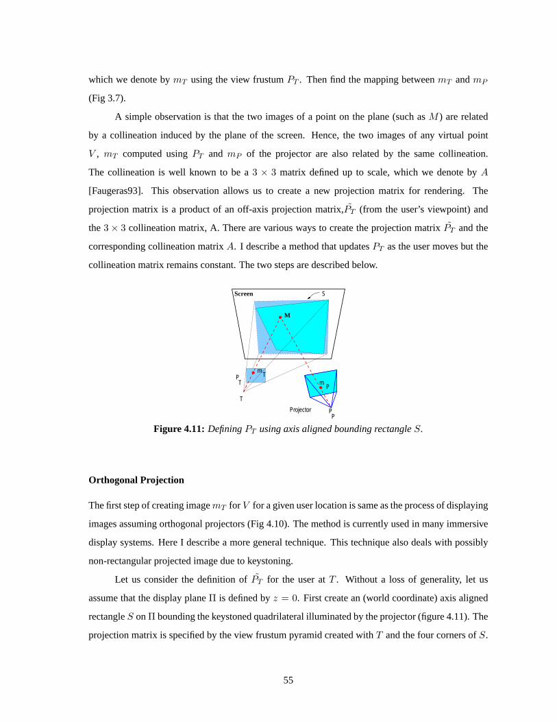
which we denote by mT using the view frustum PT . Then find the mapping between mT and mP
(Fig 3.7).
A simple observation is that the two images of a point on the plane (such as M ) are related
by a collineation induced by the plane of the screen. Hence, the two images of any virtual point
V , mT computed using PT and mP of the projector are also related by the same collineation.
The collineation is well known to be a 3 × 3 matrix defined up to scale, which we denote by A
[Faugeras93]. This observation allows us to create a new projection matrix for rendering. The
projection matrix is a product of an off-axis projection matrix,PT (from the user’s viewpoint) and
the 3 × 3 collineation matrix, A. There are various ways to create the projection matrix PT and the
corresponding collineation matrix A. I describe a method that updates PT as the user moves but the
collineation matrix remains constant. The two steps are described below.
M
Screen
T
PT
P
mT
m
S
Projector PP
Figure 4.11: Defining PT using axis aligned bounding rectangle S.
Orthogonal Projection
The first step of creating image mT for V for a given user location is same as the process of displaying
images assuming orthogonal projectors (Fig 4.10). The method is currently used in many immersive
display systems. Here I describe a more general technique. This technique also deals with possibly
non-rectangular projected image due to keystoning.
Let us consider the definition of PT for the user at T . Without a loss of generality, let us
assume that the display plane Π is defined by z = 0. First create an (world coordinate) axis aligned
rectangle S on Π bounding the keystoned quadrilateral illuminated by the projector (figure 4.11). The
projection matrix is specified by the view frustum pyramid created with T and the four corners of S.
55

Thus T is the center of projection and S on Π is the retinal plane. As the user moves, S remains the
same, but T and hence the projection matrix PT is updated.
If the projector was orthogonal, S could be the same as the rectangular area illuminated by the
projector. However, even if the area is not rectangular (because,say, the shape of framebuffer chosen
for projection is not rectangular), the projection matrix PT can be used to render correct images.
Collineation
In the second step, the image calculated assuming orthogonal projector is corrected to compensate
for the oblique projection using collineation. The collineation –between image created with PT
and the image to be rendered in projector’s framebuffer– is induced due to the plane of the screen.
The collineation matrix, A3×3 is well-known to be defined up to scale and maps pixel coordinates
from one image to a second image [Faugeras93][Criminisi98]. We need to compute the 8 unknown
parameters of A3×3 that relate the two images of V : mT due to PT , and its image in projector, mP .
mP∼= A3×3mT
mPx
mPy
1
∼=
a11 a12 a13
a21 a22 a23
a31 a32 1
mTx
mTy
1
(4.6)
where, The symbol ∼= denotes equality up to a scale factor. Note that the choice of view
frustum for PT makes this collineation independent of the user location and hence remains constant.
If the 3D positions of points on Π illuminated by four or more pixels of the projector are known, the
8 parameters of the collineation matrix, A = [a11, a12, a13; a21, a22, a23; a31, a32, 1], can be easily
calculated. Since the collineation matrix remains constant, it can be computed off-line.
4.2.2 Single-pass Rendering
We would ideally like to compute the pixel coordinates mP directly from the 3D virtual point V .
This can be achieved by creating a single 3 × 4 projection matrix, APT . Let us consider how this
approach can be used in traditional graphics pipeline. We need to create 4 × 4 version of PT ,
denoted by PT and of A, denoted by A4×4. As a traditional projection matrix, PT transforms
3D homogeneous coordinates into 3D normalized homogeneous coordinates (4 element vectors).
Typically, one can obtain the pixel coordinates after the perspective division. We create the new
56

matrix, A4×4 to transform these normalized 3D coordinates (without perspective division) to the
projector pixel coordinates but trying to keep the depth values intact,
A4×4 =
a11 a12 0 a13
a21 a22 0 a23
0 0 1 0
a31 a32 0 1
(4.7)
The complete projection matrix is P ′T = (A4×4PT ). (It is easy to verify [mPx, mPy, mPz, 1]T ∼=
A4×4PT [V, 1]T .) This achieves the desired rendering and warping using a single projection matrix
without additional cost. This is more efficient than using the general rendering framework which
requires two rendering passes. Since the image in the framebuffer is generated in a single pass, there
are no resampling artifacts. Finally, when the image is projected on any surface coplanar with Π, the
displayed virtual object appears perspectively correct. This approach is sufficient to render correct
images of virtual 3D points.
P View FrustumTz
x
T
M
Tm
SΠ
OrthogonalProjector
V
zn
P View FrustumT
Vz
x
M
T
Tm
mPA
Projector
Π
Oblique
zn
Figure 4.12: (a) First step using simple off-axis projection matrix PT (b) In the second step, warpusing collineation A. The modified projection matrix is APT .
However, if the visibility computation is based on the traditional depth buffer or z-buffer, one
important modification is necessary. In this modified algorithm there is a third logical steps. In the
first step, we compute the image of the virtual 3D scene assuming the projector is orthogonal (figure
4.12 left). Then warp this image to compensate for the oblique projection using the the collineation
between display plane and projector’s image plane (figure 4.12 right). The depth values are also
affected due to the warping, and hence, in the third step they are transformed so that they can be used
for visibility computations. However, all the three steps can be implemented using a single 4 × 4
projection matrix as in the traditional rendering using graphics hardware. In this section, I focus on
57

an application that involves front projection display system, but the techniques are also applicable to
rear projection systems such as CAVE or Immersive Workbenches.
4.2.3 Visibility using depth buffer
Although the approach described in section 4.2.1 creates correct images of virtual 3D points, it is
important to note that the traditional depth-buffer cannot be effectively used for visibility and clipping.
Let us consider this problem after we have rendered the image as described in subsection 4.2.2.
Problems with depth buffer
As we saw earlier, virtual point V is rendered using a projection matrix P ′T = A4×4PT (figure
4.12 right). The depth values of virtual points between near and far plane due to PT are mapped
to [−1, 1]. Let’s say, [mTx, mTy, mTz, mTw]T = PT [V, 1]T and the corresponding depth value is
mTz/mTw ∈ [−1, 1]. After collineation, the new depth value, is actually
mPz =mTz
(a31mTx + a32mTy + mTw)(4.8)
which (i) may not be in [−1, 1] resulting in undesirable clipping with near and far plane of the
view frustum and (ii) is a function of pixel coordinates.
Let us consider the problem of interpolation during scan conversion in traditional rendering.
The depth values (as well as color, normal and texture coordinates) at a pixel need to be computed
using a hyperbolic interpolation. Homogeneous coordinates along with a 4 × 4 perspective
projection matrix (such as PT ) achieve hyperbolic interpolation of depth values using a simpler
linear interpolation (of the reciprocal of the values). In our case i.e. when using a projection matrix
P ′T = A4×4PT , we are performing two successive hyperbolic interpolations, first for the perspective
projection and second for the collineation. At first, it may seem that a single 4 × 4 matrix would not
be able to achieve the required interpolation. Fortunately, while first matrix PT introduces hyperbolic
relationship in the depth (or ’z’) direction, the collineation matrix A4×4 leads to hyperbolic increment
along the x and y coordinate axis of the viewing coordinate system. Thus both, depth as well as screen
space, transformation can be achieved with a single 4× 4 matrix. In Appendix B, I explain the effect
of these two steps on scan conversion.
58

Thus, although the collineation does not introduce any inaccuracies in interpolation of depth
values in the frame buffer, the clipping with near and far plane creates serious problems. Some parts
of virtual objects may not be rendered.
z
(c)
1.0
x
1.0
−1.0
−1.0
(b)
(a)
ValidDepth Values
Clipped Values
Clipped Values
Figure 4.13: The plot shows depth buffer values along a scan line for points along constantdepth. (a) Using PT (b) After collineation, A4×4PT , the depth values range beyond [−1, 1] (c)With an approximation of depth-buffer, A′
4×4PT , traditional graphics pipeline can be used to renderperspectively correct images for a tracked moving user.
Approximation of depth buffer
We can achieve the rendering and warping in a single pass, however, using an approximation of the
depth buffer.
The rendering framework described the choice of view frustum for PT based on a rectangle S.
This chosen rectangle bounds the projected keystoned (quadrilateral) area (figure 4.12 right). Since
S is larger than displayed imagery, the normalized x and y coordinates due to PT , mTx/mTw and
mTy/mTw ∈ [−1, 1] for points displayed inside S. Hence,
(1 − |a31| − |a32|)mTz
(a31mTx + a32mTy + mTw)∈ [−1, 1] (4.9)
This scale factor makes sure that the resultant depth values after warping with collineation are
∈ [−1, 1]. This will avoid undesired clipping with near and far plane. Further, by construction of PT ,
the angle between projector’s optical axis and the normal of the planar surface is same as the angle
59

between the optical axis and normal of retinal plane of view frustum for PT . To summarize, The
modified projection matrix is A′4×4PT , where
A′4×4 =
a11 a12 0 a13
a21 a22 0 a23
0 0 1 − |a31| − |a32| 0
a31 a32 0 1
(4.10)
4.2.4 Multiple projectors
We can extend the same single-pass rendering and warping technique to register multiple overlapping
projectors to create larger displays on a planar wall. In this subsection, I describe a necessary
modification. More details are also available in [Raskar02b]. Some popular systems using m × n
array of projectors are PowerWall [PowerWall] and Information Mural [Humphreys99]. The major
challenge is matching the two images so that the displayed image appears seamless. Again, this is
typically achieved with rigid structure which is difficult to maintain and needs frequent alignment.
We can instead use roughly aligned projectors or even relatively oblique projectors.
mm
M
P
Screen
P2
1
12
S
P1P2A21
V
A
M
PT
Projector 1Projector 2
User T
Screen
D
Figure 4.14: Collineation between overlapping projectors on planar display surface.
Consider two overlapping projectors creating seamless images of virtual 3D scene on a shared
planar surface (figure 4.14). Let’s say the projection matrices for the two projectors are P1 and
P2. We exploit the collineation between the images in the two projector framebuffers. If the 3 × 3
collineation matrix mapping pixel coordinates from projector 1 to those in projector 2 is A21, then
the 3 × 4 projection matrix P2 can be replaced with P ′2 = A21P1.
60

Note that, as we have seen earlier, although the corresponding 4 × 4 matrix P ′2 will create
correct images of 3D virtual points, we cannot use the traditional depth buffer for visibility and
are forced to use approximated depth values. If P1 itself is a result of oblique projection, so that
P1 = A′4×4PT , the corresponding collineations A3×3, and A21 are used together. Let’s say A21T =
A21A3×3. We first create the corresponding 4 × 4 matrix A′21T−4×4 (similar to equation 4.10). We
then replace P2 with P ′2 = A21T−4×4PT to achieve correct rendering, warping and depth buffer
transformation. In practice, since it involves only 8 unknown parameters, it is easier to compute the
collineation A21 than calibrating the projector and computing the projection matrix P2.
It is also necessary to achieve intensity blending of overlapping projectors. The complete
problem of intensity feathering was addressed in the last section under generalized panoramic
displays. In this case however, due to the exact mapping defined by A21, it is very easy to calculate
the actual quadrilateral (or triangle in some cases) of overlap on screen as well as in projector image
space. The intensities of pixels lying in this quadrilateral in both projector are weighted to achieve
intensity roll-off [Lyon85][Burt83][Szeliski96] and necessary blending. The technique for intensity
blending in case of two-pass rendering are described with more details in [Raskar98c][Surati99] and
are applicable here for a single-pass rendering with minor modifications. The undesired parts of
projector image, e.g. corners of projected regions outside a defined display region can be truncated
to create large and rectangular imagery with multiple projectors. The region in projector framebuffer
is masked off by rendering a black polygon at near plane.
4.2.5 Implementation
With the help of Michael Brown and Herman Towles, I implemented a system consisting of
three overlapping projectors displaying images on a 12x8 ft planar screen. The user is tracked
with optical tracking system. The collineation between desired image for the user and the first
projector’s framebuffer is calculated using approximately 8 points. The mapping between overlapping
projectors’ pixels (again described by a collineation) are actually computed by observing individual
pixels of each of the projector with a camera. The camera field of view covers projection of all three
projectors.
During preprocessing, one needs to compute the extent of projector illumination in WC,
transformation between the tracker and WC, and the collineation A3×3. There are many ways
of computing the collineation and tracker-WC transform. For example, one can have pre-defined
61

locations on screen with known 3D coordinates (e.g. corners of the cube in CAVE, or ruled surface
on a workbench). In this case, one can manually or using a camera-feedback find which projector
pixels illuminate these markers and then compute the unknown parameters.
The origin in world coordinates (WC) is defined to be near the center of projection of the first
projector.
Usually pre-defined markers are not available, for example when one wants to simply aim
a projector at a screen and render head-tracked images. I describe a technique that computes the
collineation and transformation simultaneously. Assume the screen defines the WC: the plane Π ≡z = 0 and origin (preferably) near the center of projected quadrilateral. We take tracker readings of
locations on the screen illuminated by projector pixels. We will compute the transformation between
tracker and WC. Let us denote the tracker reading for a 3D point M by M trk. Assign one of the
measured locations illuminated by a projected pixels as origin of WC, O, (the tracker measurement
effectively giving the translation between origins in both coordinate systems). To find the relative
rotation, find the best-fit plane in tracker coordinates for the screen, giving the normal to the screen
denoted by vector r3. Assign one illuminated pixel in approximate horizontal direction, Mx, as a
point on WC x-axis. Find the vector M trkx −Otrk in tracker coordinates, normalize it to get vector r1.
The rotation is R = [r1; r3× r1; r3]. The transformation is [R (−R ∗Otrk); 0 0 0 1]. Find the 3D
coordinates of points on screen illuminated by projector pixels and finally compute the collineation
A3×3. The collineation allows computation of extents of projector illumination in WC.
Wei-Chao Chen at UNC has implemented a stereo display using completely overlapping two
projectors. One projector is used to display images for the left eye and the second for the right eye.
The two images are distinguished by using polarizing optical filters on the projectors and eye-glasses.
He computed PT for each projector and the common collineation matrix A3×3 using the UNC HiBall
tracker. The same tracker is later used for tracking user’s head-motion [Chen00a].
For multiple overlapping projectors, we actually used a camera to find collineation between the
projected images and also use the same information for computing weighting functions for intensity
blending. The use of camera feedback for multiprojector displays is described in more detail in the
section 4.2.
62

Summary of Techniques
Here are the sequence of steps suggested for using a single oblique projector to create a planar
immersive display. During pre-processing :
• Turn on (four of more) projectors pixels, mP1...mPn and find in tracker coordinates, the
position of the illuminated 3D points on the plane, M1...Mn.
• Compute equation of plane and transform the coordinate system so that it is coplanar with
Π ≡ z = 0. We will denote transformed points by MΠi .
• Find collineation, AΠP , between MΠi and mPi. Using AΠP , compute 3D points on Π
illuminated by corners pixels of the projector. Then find axis aligned rectangle, S, that bounds
the four corners of the illuminated quadrilateral (the min and max of x and y coordinates).
• For a random user location T , compute PT for a frustum created with S. Find normalized image
coordinates mT i = PT MΠi . Compute the collineation A3×3, between mT i and projector pixels
mPi. Create A′4×4 from A3×3 using eqn 4.10.
During run-time at every frame:
• Update T for the new user location and compute PT (using graphics API function such as
glFrustum).
• Use A′4×4PT as the new projection matrix during rendering.
As one can see, the only human intervention involved is finding 3D tracker readings Mi for screen
points illuminated by four of more projector pixels mPi.
4.2.6 Applications
The new techniques can be easily used in current immersive display systems. For example, in
immersive workbenches, it is much easier to take tracker readings at a few points (illuminated by
the projector), compute the collineation off-line and then use the modified projection matrix for rest
of the session. There is no need to worry about achieving some pre-defined alignment of the projector.
The transformation between tracker and projected screen is also included in the steps described above.
In CAVE, one can roughly align projectors so that they actually create images larger than
usable size of the screen. Since the usable screen sections are already marked (we can assume that
63

the markers are stable as compared to the configuration of projectors and mirror), one needs to only
find the projector pixels that illuminate those markers. The corners of the cube also allow geometric
continuity across the screens that meet at right angles. The part of the imagery being projected outside
the usable screen area can be masked during rendering.
Finally, this technique is useful for quickly creating a simple immersive display by setting up
a screen, a projector and a tracking system. For stereo displays, the off-axis projection matrix PT is
different for the left and right eye, but the collineation matrix A3×3 remains constant.
Figure 4.15: For a given plane of focus, projector can be treated as a pin-hole device. Thepictures here show experimental verification of linear perspective projection. Straight line segmentsin image plane appear straight on a planar display surface (top). Further, line segments projectedby overlapping projectors can be aligned to sub-pixel accuracy using homography (bottom left).Example of overlapping text in a warped image (bottom right).
4.2.7 Issues
The techniques are valid only when the assumed pin-hole projection model (dual of the pin-hole
camera model) is valid. However, as seen in Figure 4.15, this assumption is valid for even low-cost
single-lens commercial projectors. However, projectors typically have a limited depth of field and
64

hence when they are oblique all pixels may not be in focus. The imagery is in focus for only a limited
range of angles between the screen plane normal and the projector optical axis. The intensities across
the screen are also not uniform when projector image plane is not parallel to the screen. However,
this can be compensated by changing the intensity weights during rendering (using, for example alpha
blending). In the case of multi-projector tiled display, the alpha-blending is performed for the overlap
region and hence it can be extended to include intensity correction for oblique projector without
any additional cost. The transformation of depth-buffer values essentially reduces the usable range
of depth values and hence the depth resolution is also decreased. In terms of resolution, rendering
speed and visibility computation, the displayed images were visually equivalent to those generated
by orthogonal projection systems.
4.2.8 Discussion
The technique presented in this section allows rendering correct images even when the projectors are
positioned without any precise alignment. Techniques for pre-warping the images using a two-pass
rendering are already available. However, the two major advantages of this technique are that it
does not increase the cost of rendering and does not introduce resampling artifacts such as aliasing.
The possibility of rendering images with oblique projectors that are visually equivalent can eliminate
the need of cumbersome electro-mechanical adjustment of projectors, screens and the supporting
structure.
Figure 4.16: Top row: Images displayed by oblique projector which created keystoned imagery andbut corrected using collineation. Bottom row: Displayed image without and with intensity blending.
65

4.3 Summary
The rendering framework described in the previous chapter allows us to re-formulate the classic
projector-based applications. I used two examples, panoramic multi-projector environments and tiled
planar displays. The major issue in the current display systems is the cumbersome and expensive
procedure used to maintain geometric registration for the sake of creating seamless images. The
advantage of re-stating those problems in the context of the new rendering framework is that, we
can achieve the same results using many reasonable variations of the original design. I identified the
parallels between panoramic photo-mosaics and the generalized panoramic display described in this
chapter, to promote the projector as the dual of a camera. In the next chapter, I take this concept
further and describe a new class of visualization methods.
66

CHAPTER 5
Novel Applications
When we project images of 3D objects on physical display surfaces, we in effect introduce those
virtual 3D objects in the real world around us. In traditional projector-based displays, the virtual
objects appear on a flat screen. However, once we understand the relationship between the projector
and the geometry of the surface it illuminates, we can project correct images of virtual objects on
physical surface of various geometric shapes. We can essentially treat those physical surfaces as ’3D
screen’s.
The rendering framework enables a new class of applications that insert the virtual objects
directly in our surroundings on such 3D screens. In this chapter I introduce new visualization
concepts. The main concept is a new form of augmented reality without a need for head-mounted
display. I call this spatially augmented reality (SAR). Then, I describe in more detail a special case of
SAR, to reproduce computer generated surface appearances for physical objects using shader lamps.
The key idea here is the conjunction of a physical object and its geometrical definition (stored
as a virtual object in a computer’s memory). The interdependence between the co-existing virtual and
physical incarnation of an object is exploited using projected light that either enhances or modifies
the appearance of a world made of some of those objects. The result of computation and the outcome
of computer graphics rendering is seen in the context of the physical world around us. In this chapter,
I explain how the rendering framework plays a new role in terms of the photometric properties of the
illuminated surfaces. The rendering framework provides tools that make the realization of the ideas,
described below, practical.

5.1 Spatially Augmented Reality
In Spatially Augmented Reality (SAR), the user’s physical environment is augmented with images
that are integrated directly in the user’s environment, not simply in their visual field [Raskar98d,
Raskar99b]. For example, the images could be projected onto real objects using digital light
projectors, or embedded directly in the environment with flat panel displays. For the purpose of
this discussion I will focus on projector-based augmented reality. While the approach has certain
restrictions, it offers an interesting new method to realizing compelling illusions of virtual objects
coexisting with the real world. The images could appear in 2D, aligned on a flat display surface,
or they could be 3D and floating above a planar or even a non-planar surface. In the most basic
applications, SAR combines the benefits of traditional spatially immersive displays and augmented
reality displays. I compare SAR with the two and then describe further possibilities.
Figure 5.1: HMD-AR and SAR
5.1.1 Comparison with Spatially Immersive Displays
Spatially immersive displays (SID), such as CAVE and Immersive workbenches involve planar or
near-planar curved display surfaces. In the last chapter, I presented techniques to extend the SID
surface geometry to non-planar configurations. In SAR, in addition to planar and non-planar surfaces,
the idea is to illuminate closed objects. In traditional SID, the user stands inside or in front of the
displayed images. With SAR, we can extend this to outside-looking-in displays where the user can
68

walk around the illuminated objects. Similarly, the projectors can be positioned to surround the
object.
In traditional SID, we treat the illuminated segment of the display surface as a portal into a
virtual scene. To create immersive images, the goal is to make the display surface imperceptible to
the user. For this reason, a smooth continuous screen with no visible shape features is preferred. The
specific location or even the local shape of the display surface is not critical. In SAR, the geometric
shape of the physical surface and the virtual objects is strongly correlated. In some cases, the physical
surface shares the approximate scale and form with virtual object, while in other cases, e.g. as
described in the next section for shader lamps, the physical shape is identical to the virtual object
geometry.
5.1.2 Comparison with Head Mounted Augmented Reality Display
Head-mounted optical see-thru or video see-thru displays are commonly used to superimpose images
of virtual objects in the user’s view. In [Bryson97] various advantages of spatially immersive displays
over head-mounted displays have been noted. A key benefit of SAR is that the user does not need
to wear a head-mounted display (HMD). However, the user may be tracked to present virtual objects
floating on top of physical surfaces or to display view-dependent surface properties. As shown in
Figure 5.1, in HMD-AR, the view is augmented while in SAR, the virtual information is presented
on top of the real objects. While not appropriate for every augmented reality application, this altered
display mode results in significant advantages.
The registration problem in SAR becomes somewhat unusual one of having to register
projected 2D imagery with 3D physical geometry. In HMD-AR, the registration problem involves
aligning displayed images with respect to the user’s view of the physical geometry. The crucial
difference is that, in SAR, the 2D imagery exists on a virtual image plane that remains attached to
the (fixed) physical displays surface, independent of the user location. This is similar to the situation
in SID and the dynamic visual mis-registration error is virtually unaffected by viewpoint orientation
error. The viewpoint position error results in a form of virtual object shear rather than a simple
translation in relative position.
The occlusion relationship in SAR is also different than in see-through AR system. In SAR,
a real object can occlude the virtual object. Thus, for example, bringing your hand in front of the
face will occlude the virtual object behind maintaining the illusion that the virtual object exists in the
69

real world. On the other hand, a virtual object cannot obstruct the view of a real object even if it is
intended to float in front of that virtual object.
Figure 5.2: Spatially augmenting large environment (Kok-lim Low et al, 2001). (Top left) Virtualmodel; (Top right) Physical display environment constructed using Styrofoam blocks; (Bottom row)Augmented display. Note the view dependent nature of the display, the perspectively correct viewthrough the hole in the wall and the windows.
5.1.3 Applications
The idea of SAR is best used when virtual objects are close to the physical objects on which they
are displayed. For example, an architect can augment a tabletop scaled model of a house or building
using a projector. She can start with a very simple neutral colored cardboard model and its geometric
CAD representation. Then it is easy to add virtual objects such as door, windows, chimneys. She can
also visualize underground water pipes or support structure inside the building.
A compelling example of spatial augmentation is the application aimed at walk-thru of virtual
human-sized environments built by Kok-lim Low et. al. in the Being There project at UNC [Low01].
Instead of building an exact detailed physical replica for projection, the display is made of simplified
versions. For example, primary structures of building interiors and mid-sized architectural objects
70

(walls, columns, cupboards, tables, etc.), can usually be approximated with simple components
(boxes, cylinders, etc.). As seen in the figure 5.2, display is made of construction Styrofoam blocks.
The main architectural features that match the simplified physical model retain 3D auto-stereo, but the
other details must be presented by projecting view-dependent images. Nevertheless, the experiment
to simulate a building interior is is convincing and provides a stronger sense of immersion when
compared to SID, as the user is allowed to really walk around in the virtual environment. However,
strategic placement of projectors to allow complete illumination and avoiding user shadows is critical.
In the next section, I describe a more restricted version of SAR but it has many interesting
characteristics that make a widespread use possible.
5.2 Shader Lamps
In this section, I describe a special case of SAR. The idea is to replace a physical object with
its inherent color, texture, and material properties with a neutral object and projected imagery,
reproducing the original appearance directly on the object. Furthermore the projected imagery can be
used to reproduce alternative appearances, including alternate shading, lighting, and even animation.
The approach is to effectively ”lift” the visual properties of the object into the projector and then
re-project onto a neutral surface. Greg Welch coined the phrase shader lamps to describe this mode
of operation for projectors [Raskar01c]. Consider the effect shown in figure 5.3. The underlying
physical object is a white diffuse vase. (The other objects such as the book and flowers are also real
objects.) Can we make this white vase appear to look like it is made of marble, plastic or metal? Can
we change the color or texture? The pictures below show that the vase can be effectively ’painted’
by projecting an image with view-independent diffuse shading, textures and intensity correction.
The view-dependent effects such as specular highlights are generated for a given user location by
modifying reflectance properties of the graphics model. The figure shows appearance of a red plastic
and a green metallic material on the clay vase.
Although, there have been other attempts at augmenting appearances of objects by projecting
color or texture, those effects are very limited and have been achieved for only specific applications.
In this section, I show that the real challenges to realizing this as a new medium for computer graphics
lies in addressing the problems related to complete illumination of non-trivial physical objects. The
approach presented here offers a compelling method of visualization for a variety of applications
71

Figure 5.3: The surface appearance of a neutral colored object is changed by ’painting’ it withprojected light.
including dynamic mechanical and architectural models, animated or “living” dioramas, artistic
effects, entertainment, and even general visualization for problems that have meaningful physical
shape representations. I present and demonstrate methods for using multiple shader lamps to animate
physical objects of varying complexity, from a flower vase (figure 5.3), to some wooden blocks, to a
model of the Taj Mahal (figure 5.4).
Figure 5.4: Underlying physical model of Taj Mahal and enhanced with shader lamps.
72

5.2.1 Motivation
Graphics in the World
Using geometric models and physically-based rendering, or image-based models and image-based
rendering, computer graphics techniques attempt to “capture” the real world in the computer, and
then to reproduce it visually. In later years work has been done to explore what is in effect the
reversal of this relationship, to insert computer graphics in the real world. Primarily this has been
done visually for either special effect in movies, or in real time for augmented reality. Most recently
there is a new trend to use light projectors to render imagery directly in our real physical surroundings.
Examples include the Luminous Room [Underkoffler99] and the Office of the Future [Raskar98b] at
UNC. What I am pursuing here is a more complete extension of these ideas, the incorporation of
three-dimensional computer graphics and animation directly into the real world all around us.
Stimulation and Communication of Ideas
As noted by Jim Kajiya in 1996 [Kajiya96], ”Computer Graphics is useful not only for augmenting
one’s own imagination but for stimulating the imagination of others. We can use it to codify, transmit,
store, and communicate experience and ideas. Computer graphics as a medium is only just emerging.”
With respect to the stimulation and communication of ideas, it is surprising that despite the many
advances in computer graphics, architects and city planners (for example) still resort to building
physical models when the time comes to seek client or constituent approval. (See for example
[Howard00].) The architects that I have spoken with, and many books on the subject, note that
while it is true that designers cannot do without CAD tools any more, ”It [the computer] cannot
replace the actual material experience, the physical shape and the build-up of spatial relationships.”
[Knoll92]. Even in this day of computer animation, animators often sculpt a physical model of a
character before making computer models. This was the case with Geri in ”Geri’s Game (Pixar
Animation Studios) for example. One reason for these sentiments and practices is that the human
interface to a physical model is the essence of “intuitive”. There are no widgets to manipulate, no
sliders to move, and no displays to look through (or wear). Instead we walk around objects, moving in
and out to zoom, gazing and focusing on interesting components, all at very high visual, spatial, and
temporal fidelity. We all have a lifetime of experience with this paradigm. The goal of shader lamps
73

Figure 5.5: Concept of shader lamps. Physical textures (above) and shader lamp textures (below)
is to enjoy the many advantages of the natural physical interface, in particular the auto-stereoscopic
nature of viewing physical objects, and the richness of computer graphics.
Image-Based Illumination
Normally in the physical world, the color, texture, and lighting associated with the surface of a
physical object are an integral part of the object. In computer graphics this is typically modeled
with a bidirectional reflection distribution function (BRDF) for the surface. When we illuminate the
object with a white light, the surface reflects particular wavelengths of light, and we perceive the
respective surface attributes. Because our perception of the surface attributes is dependent only on
the spectrum of light that eventually reaches our eyes, we can shift or re-arrange items in the optical
path, as long as the spectrum of light that eventually reaches our eyes is the same.
Many physical attributes can be effectively incorporated into the light source to achieve a
perceptually equivalent effect on a neutral object. Even non-realistic appearances can be realized.
This concept is illustrated in Figure 5.5. We can use digital light projectors and computer graphics to
form shader lamps that effectively reproduce or synthesize various surface attributes, either statically,
dynamically, or interactively. While the results are theoretically equivalent for only a limited class
of surfaces and attributes, the results, described below, are quite realistic and compelling for a broad
range of applications.
The need for an underlying physical model is arguably unusual for computer graphics, however
it is not for architects [Howard00], artists, and computer animators. In addition, various approaches
74

to automatic three-dimensional fabrication are steadily becoming a available. Methods include
Laminate Object Manufacturing, Stereolithography, and Fused Deposition. It is not unreasonable
to argue that three-dimensional printing and faxing is coming. In the mean time, if necessary one can
use a 3D probe device. I used such a device (Faro) for the Taj Mahal model shown in figure 5.4.
5.2.2 What is New
New contributions of this research presented in this section are as follows.
• I introduce shader lamps as a new mode of visualizing 3D computer graphics. The idea treats
illumination basically as a 3D perspective projection from a lamp, and thus, it can be created
using traditional 3D computer graphics. I present techniques that can replace not just textures,
i.e. diffuse component, but can reproduce virtually any BRDF appearance.
• I present new algorithms to make the process of illumination practical. I first identify a simple
radiance adjustment equation for guiding the rendering process and then present methods for
the corresponding intensity correction.
• I introduce a new algorithm for determining pixel weights and computing feathering intensities
across transitions in projectors’ regions of influence in the presence of self-occlusions and
depth discontinuities.
5.2.3 Previous Work
Theater and entertainment
Naimark [Naimark84] used a rotating movie camera to film a living room, replete with furniture and
people. The room and furniture were then painted white (neutral), and the captured imagery was
projected back onto the walls using a rotating projector that was precisely registered with the original
camera. This crucial co-location of the capturing and displaying devices is common to most of the
current demonstrations that use pre-recorded images or image-sequences. A limited but compelling
example of this idea is the projection of pre-recorded video to ani-mate four neutral busts of singing
men in the Walt Disney World “Haunted Mansion” (figure 5.6). In addition, a patented projector
and fiber-optic setup animates the head of the fictional fortune teller “Madame Leota” inside a real
crystal ball [Liljegren90]. Slides of modified photographs augmented with fine details are also used
75

Figure 5.6: From the Walt Disney World ”Haunted Mansion,” still cells of animated faces projectedonto neutral busts (left), and Madame Leota’s head (right)
with very bright projectors to render imagery on a very large architectural scale. For example, in
1952 Paul Robert-Houdin used sounds and colored lights on a building for nighttime entertainment.
A well-known modern realization of this idea is the Son et Lumiere (light show) on the Blois castle
in the Loire Valley (France). In addition the medium is now being used elsewhere around the world
at sites such as the Forum (Rome), the Parthenon (Athens); Greenwich Palace; Independence Hall
(Philadelphia); the Pyramids of Giza (Cairo); the Red Fort (Delhi); and the ruins of Teotihuac’n (near
Mexico City).
Influenced by Son et Lumiere, Marc Levoy [Levoy00] has experimented with projection of
imagery onto small-scale fabricated statues. Instead of photographs, he first renders an image of a
stored 3D model similar to our techniques and then manually positions the projector to geometrically
register the projected image. The HyperMask project [Morishima00], an exception in terms of
automatic registration, involves projecting an animated face onto a moving mask for storytelling.
All these systems create compelling visualizations. However, the cumbersome alignment process can
take several hours even for a single projector. My technique avoids this problem by exploting the
proposed geometric framework to form a 3D geometric understanding using well-known computer
vision techniques described and then moves beyond simple image projection to reproduce reflectance
properties.
Tangible luminous interfaces
The Luminous Room project treats a co-located camera-projector pair as an I/O bulb to sense and
inject imagery onto flat surfaces in the real physical surroundings of a room or a designated workspace
[Underkoffler99]. The work we present here is distinct from, but complementary to, this work. A
primary distinction is that their main focus is interaction with the information via luminous (lit)
and tangible interfaces. This focus is exemplified in such applications as ”Illuminating Light” and
76

”URP” (urban planning). The latter arguably bears closest resemblance to our work, in particular
the interactive simulation of building shadows from sunlight. The approach is to recognize the 2D
physical objects (building ”phicons”) lying in a plane, track their 2D positions and orientations in the
plane, and project light from overhead to reproduce the appropriate sunlight shadows. However, we
are primarily interested in the use of physical objects as truly three-dimensional display devices for
more general computer graphics, visualization and aesthetic (artistic) applications.
Modeling and rendering architecture from photographs
In the “Facade” project, a sparse set of photographs are used to model and render architectural
monuments [Debevec96]. This is a good example of a hybrid approach of using geometry and images
to reproduce physical human-made structures. The main challenges are related to the occlusion,
sampling, and blending issues that arise when re-projecting images onto geometric models. They face
these challenges with computer imagery and analytic models, while in shader lamps, I have to face
them with real (light projected) imagery and physical models. It would be useful to use Facade tools
to build a hybrid geometry and image model of a university campus, and then use the shader-lamp
techniques to animate a scaled physical model, effectively creating a “living diorama” of the campus.
To realize the general application of this technique, one must, among other things, have a method
for pre-warping the imagery to “fit” the physical object so that it appears correct to local viewers.
Some limited 2D warping effects have been achieved by [Dorsey91] to model the appearance of
theatrical backdrops so that they appear correct from the audience’s perspective. As described in the
previous chapter, the two-pass warping method I presented [Raskar98b] can be used for projecting
onto non-planar surfaces. I exploit the rendering framework to illuminate potentially non-convex or a
disjoint set of objects, and present new techniques to address the alignment, occlusion, sampling and
blending issues.
5.2.4 The Rendering Process
I introduce the idea of rearranging the terms in the relationship between illumination and reflectance
to reproduce equivalent radiance at a surface. As shown in flatland in Figure 5.7, the radiance in a
certain direction at point (x) , which has a given BRDF in the physical world (left), can be mimicked
by changing the BRDF and illuminating the point with a appropriately chosen light source, e.g. a
projector pixel (right). Below I identify a radiance adjustment equation for determining the necessary
77

eye
x
L
Li 2
eye θ2
θ1
x
L'
θ θ PθLi 1
LPShading
view
Rendering view
Figure 5.7: The radiance at a point in the direction (right) The radiance as a result of illuminationfrom a projector lamp. By rearranging the parameters in the optical path, the two can be made equal.
intensity of a projector pixel, given the position and orientation of the viewer and the virtual scene.
For a more systematic rendering scheme, I describe the notion of separating the rendering view-
the traditional virtual camera view, from the shading view-the position of the viewer for lighting
calculations.
First, let us consider the rendering equation, which is essentially a geometrical optics
approximation as explained in [Kajiya86]. The radiance at a visible surface point (x) in the direction
(θ, φ) that would reach the observer of a physical realization of the scene is
L(x, θ, φ) = g(x, θ, φ)(Le(x, θ, φ) + h(x, θ, φ)) (5.1)
where
h(x, θ, φ) =∫
iFr(x, θ, φ, θi, φi)Li(x, θi, φi)cos(θi)dωi (5.2)
and g(x, θ, φ) is the geometry term (visibility and distance), Le(x, θ, φ) is the emitted radiance
of the point (non-zero only for light sources), and Fr(x, θ, φ, θi, φi) is the bidirectional reflection
distribution function (BRDF) for the point. The integral in h(x, θ, φ) accounts for all reflection of
incident radiance Li(x, θi, φi) from solid angles dωi. Radiance has dimensions of energy per unit
time, area and solid angle.
Treating the projector lamp as a point emitter, the radiance due to direct projector illumination
at the same surface point at distance d(x) but with diffuse reflectance ku(x) is given by,
L′(x, θ, φ) = g(x, θ, φ)ku(x)IP (x, θP , φP )cos(θP )
d(x)2(5.3)
where IP (x, θP , φP ) = radiant intensity of projector in the direction (θP , φP ), and is related to
a discretized pixel value via filtering and tone representation.
78

We can reproduce equivalent radiance L′(x, θ, φ) equivalent to L(x, θ, φ) for a given viewer
location, by solving Eqn. 5.3 for IP :
IP (x, θP , φP ) =L(x, θ, φ)d(x)2
ku(x)cos(θP )for, ku(x) > 0 (5.4)
Thus, as long as the diffuse reflectance ku(x) is nonzero for all the wavelengths represented
in L(x, θ, φ) , we can effectively represent the surface attribute with appropriate pixel intensities. In
practice, however, the range of values we can display are limited by the brightness, dynamic range
and pixel resolution of the projector. Thus for example, we can not make a red surface appear green
because for the wavelength of light corresponding to green color, the diffuse reflectance of a red
object (kgreenu = 0). We also cannot project on objects with mirror-like BRDF because the diffuse
reflectance is zero.
The rendering process here involves two viewpoints: the user’s and the projector’s. A
simple approach would be to first render the image as seen by the user, which is represented by
L(x, θ, φ) , and then use traditional image-based rendering techniques to warp this image to generate
the intensity-corrected projected image, represented by IP (x, θP , φP ) [Chen93, McMillan95].
Thus, in one way, this is equivalent to rendering and warping the image followed by intensity
correction. This is the 2-pass method of the general rendering framework. For a changing
viewer location, view-dependent shading under static lighting conditions can also be implemented
[Debevec98, Levoy96, Gortler96]. However, the warping can be avoided in the case where the display
medium is the same as the virtual object. A special case of the general rendering method is required:
For a single-pass rendering, we treat the moving user’s viewpoint as the shading view. Then, the
image synthesis process involves rendering the scene from the projector’s view, by using a perspective
projection matrix that matches the projector’s intrinsic and extrinsic parameters, followed by radiance
adjustment. The separation of the two views offers an interesting topic of study. For example, for a
static projector, the visibility and view-independent shading calculations can be performed just once
even when the user’s viewpoint is changing.
To realize a real-time interactive implementation I use conventional 3D rendering APIs,
which only approximate the general rendering equation. The BRDF computation is divided into
view-dependent specular, and view-independent diffuse and ambient components. View-independent
shading calculations can be performed by assuming the rendering and shading view are the
same. (The virtual shadows, also view-independent, are computed using the traditional two-pass
79

Figure 5.8: (a) A green paper illuminated with white light (b) The white diffuse surface on the rightis illuminated with green light. In this special case, the secondary scattering off the white surfacebelow is similar for both parts
shadow-buffer technique.) For view-dependent shading, such as specular highlights (Figure 5.3),
however, there is no existing support to separate the two views. A note at the end of this section
describes a simple modification that allows rendering view-dependent shading without additional
cost.
Secondary Scattering
Shader lamps are limited in the type of surface attributes that can be reproduced. In addition,
since we are using neutral surfaces with (presumed) diffuse characteristics, secondary scattering is
unavoidable and can potentially affect the quality of the results. When the underlying virtual object
is purely diffuse, sometimes the secondary scattering can be used to our advantage. The geometric
relationships, also known as form factors, among parts of the physical objects, are naturally the same
as those among parts of the virtual object. Consider the radiosity solution for a patch i in a virtual
scene with m light sources and n patches:
Bi−intended = kdi
∑j
BjFi,j = kdi(∑
1≤j≤m
BjFi,j +∑
m+1≤j≤m+n
BjFi,j) (5.5)
Here kd is the diffuse reflectance, Bj is the radiance of patch j, and Fi,j is the form factor
between patches. Using shader lamps to reproduce simply the effect of direct illumination (after
radiance adjustment), we are able to generate the effect of m light sources:
Bi−direct = kdi
∑1≤j≤m
BjFi,j (5.6)
80

However, due to secondary scattering, if the neutral surfaces have diffuse reflectance ku, the
perceived radiance also includes the secondary scattering due to the n patches, and that gives us
Bi−actual = Bi−direct + Bi−secondary = kdi
∑1≤j≤m
BjFi,j + ku
∑m+1≤j≤m+n
BjFi,j (5.7)
The difference between the desired and perceived radiance is
|(kdi − ku)(∑
m+1≤j≤m+n
BjFi,j)| (5.8)
Thus, in scenarios where kd and ku are similar, we get approximate radiosity for “free” –
projection of even a simple direct illumination rendering produces believable “spilling” of colors on
neighboring parts of the physical objects. From the equation above, the secondary contribution from
the neutral surfaces is certainly not accurate, even if we reproduce the first bounce exactly,. The
difference is even larger when the virtual object has non-lambertian reflectance properties. In some
cases it may be possible to use inverse global illumination methods so that the projected image can
more accurately deliver the desired global illumination effect. Figure 5.8 shows a green and a white
paper with spill over from natural white and projected green illumination. In this special case, the
secondary scattering off the horizontal white surface below is similar for both parts.
Illumination of All Visible Surfaces
One may wonder, given a physical object, what is a good set of viewpoints for the lamps, so that every
visible surface is illuminated by at least one lamp. This problem is addressed by [Stuerzlinger99],
where he finds, using a hierarchical visibility algorithm, a set of camera viewpoints such that every
visible part of every surface is imaged at least once. The problem of determining an optimal set of
viewpoints is NP-hard and is related to the art gallery problem [O’Rourke87] known in the field of
computational geometry.
5.2.5 Methods
The image-based illumination of physical objects has been explored by many. But, I believe, two main
challenges have kept the previous efforts to only expensive, large scale, or one-off implementations.
81

(a) First, the geometric registration problem, which is cast as matching the projection of a single
2D image with an object. The projection of a perspective device has up to 11 degrees of
freedom (6 external and 5 internal) [Faugeras93], therefore, any effort to manually achieve the
registration is likely to be extremely tedious. We propose a new simple technique below.
(b) The second problem, which appears to be largely unexplored, is the complete illumination
of non-trivial physical objects in presence of shadows due to self occlusion. I illuminate the
shadowed parts of the object by adding more projectors and then address the issue of merging
overlapped images from multiple projectors.
With the advent of digitally-fed projectors and real-time 3D graphics rendering, a new
approach for image-based illumination is now possible. I approach these problems by exploiting
the 3D geometric relationship between the projector, display surface and the user, as described in the
proposed framework. Below, I describe an important intensity correction step and the solution for
dealing with self-shadows.
In what follows, I describe the actual procedure I, along with my colleague Kok-lim Low, used
to achieve the results shown in the images in this chapter.
Authoring and Alignment
One of the important tasks in achieving compelling visualization is to create the association between
the physical objects and the graphics primitives that will enhance those objects when projected. For
example, how do we specify which texture image should be used for the face of a building model,
or what color distribution will look better for a physical object? We need the physical object as
well as its geometric 3D representation, and real or desired surface attributes. As mentioned earlier,
many hardware and software solutions are now available to scan/print 3D objects and capture/create
highly detailed, textured graphics models. I have demonstrated how the authoring can also be done
interactively by “painting” directly on top of the physical objects. I have also shown how the result of
the user interaction can be projected on the objects and also stored on the computer. Ideally, a more
sophisticated user interface would be used to create and edit graphics primitives of different shape,
color and texture.
To align a projector, first we approximately position the projector and then adapt to its
geometric relationship with respect to the physical object. That relationship is computed by finding
82
projector’s intrinsic parameters and the rigid transformation between the two coordinate systems.
This is a classical computer vision problem [Faugeras93] addressed in the last chapter and solved
using camera-based feedback. Here we use a different approach. We take a set of fiducials with
known 3D locations on the physical object and find the corresponding projector pixels that illuminate
them. This allows us to compute a 3 × 4 perspective projection matrix up to scale, which is
decomposed to find the intrinsic and the extrinsic parameters of the projector. The rendering process
uses the same internal and external parameters, so that the projected images are registered with the
physical objects.
Intensity Correction
The intensity of the rendered image is modified on a per-pixel basis to take into account the
reflectance of the neutral surface, the local orientation and distance with respect to the projector
using Equation 5.4. Since the surface normals used to compute the 1/cos(θP ) correction are
available only at the vertices in polygonal graphics models, we exploit the rendering pipeline for
approximate interpolation. We illuminate a white diffuse version of the graphics model (or a model
matching appropriate ku(x) of the physical model) with a virtual white light placed at the location
of the projector lamp and render it with black fog for squared distance attenuation. The resultant
intensities are smooth across curved surfaces due to shading interpolation and inversely proportional
to (d(x)2/ku(x)cos(θP )) factor. To use the limited dynamic range of the projectors more efficiently,
we do not illuminate surfaces with |θP | > 60 (since, for |θ| ∈ [60, 90] the range 1/cos(θ) ∈ [2,∞]).
This avoids the low sampling rate of the projected pixels on oblique surfaces and also minimizes the
mis-registration artifacts due to any errors in geometric calibration. During the calculations to find
the overlap regions (described below), highly oblique surfaces are considered not to be illuminated
by that projector. See Figure 5.10 for an example.
Occlusions and Overlaps
For complete illumination, using additional projectors is an obvious choice. This leads to the
more difficult problem of seamlessly merging images from multiple projectors. A naive solution
may involve letting only a single projector illuminate any given surface patch. But, there are two
main issues when dealing with overlapping CRT, LCD or DLP projectors, which compel the use
of feathering (or cross-fading) of intensities. The first is the lack of color equivalence between
83

A BProjectors
id
A
B
A
B A
B
(a) B′
B′
A+B′
A+B
Projected Surface
A+B′
(b)
A BProjectorss
hgd e f
A
A
B
B
A
B A
B
(c) B′
A+B′
B′
A+B′
Overlapbuffer 1 1 1
22
2
i
(d)
Figure 5.9: Intensity weights using feathering methods. The plots show the contribution of projectorsA, B and B’ and the resultant accumulation A+B and A+B’ along the lit planar surface. Ourtechnique, shown in (d), creates smooth weight transitions. (a) Simple intensity ramps on planaroverlap create smooth transitions. (b) Weights computed using surface normals are no sufficient. (c)Occluders create sharp transitions (d) Our solution, which considers depth continuity, maintains thelocal smoothness of intensity weights.
84

neighboring projectors [Majumder00], due to manufacturing process and temperature color drift
during their use. The second is our desire to minimize the sensitivity to small errors in the estimated
geometric calibration parameters or mechanical variations.
Feathering, as described in Chapter 2 and 3, is commonly used to generate seamless panoramic
photomosaics by combining several views from a single location [Szeliski97]. Similar techniques
are exploited in multi-projector wide-field-of-view displays [Panoram, Trimensions, Raskar99a], and
two-dimensional arrays of flat projections. In such cases, the overlap region is typically a (well-
defined) contiguous region on the display surface as well as in each projector’s frame buffer. In
the algorithm used in [Szeliski97, Raskar99a] the intensity of a pixel is weighted proportional to
the Euclidean distance to the nearest boundary (zero contribution) pixel of the (projected) image.
The per-pixel weights are in the range [0, 1]. They are multiplied to the pixel intensities in the final
rendered image. The pixels weights near the boundary of a source image are near zero and the pixels
contribute very little, so that there is a smooth transition to the next source image. This leads to
the commonly seen intensity roll-off as shown in Figure 5.9(a). Under ideal conditions and assuming
color equivalence, the weight contribution of both projectors A+B adds up to 1. Even when projector
B’s color response is different than that of A (say, attenuated-shown as B′), the resultant A + B′
(shown in blue) transitions smoothly in the overlap region.
This weight assignment strategy works well only when the target image illuminates a smooth
continuous surface at and around the overlap. In our case, the physical model is usually made up
of non-convex objects or a collection of disjoint objects resulting in shadows, fragmented overlap
regions and, more importantly, overlap regions containing surfaces with depth discontinuities, as
shown in Figure 5.9(c) with a simple occluder. Now, with unequal color response, the resultant weight
distribution A + B′ has offending sharp changes, e.g. at points f and g. This situation is analogous
to image-based rendering (IBR), where warping a single depth-enhanced image creates dis-occlusion
artifacts. When multiple source images are warped to the target image, the color assigned to a pixel
needs to be derived (from either a single image where they overwrite each other or) as a weighted
combination of corresponding pixels from source images. The feathering, which actually blurs the
result, is usually necessary to overcome (minor) color difference in corresponding pixels in input
images and to hide ghosting effects (due to small mis-registration errors). One of the few solutions
to this is proposed by [Debevec98], in which they scale the intensities by weights proportional to
the angles between the target view and the source views. As mentioned in their paper, “it does not
85

guarantee that the weights will transition smoothly across surfaces of the scene. As a result, seams can
appear in the renderings where neighboring polygons are rendered with very different combinations
of images.” The plots in Figure 5.9(b) show a sample weighting scheme based on a similar idea and
the corresponding problems. Below, we present a global solution using a new feathering algorithm
that suits IBR as well as shader lamps.The algorithm is based on the following guidelines:
1. The sum of the intensity weights of the corresponding projector pixels is one
so that the intensities are normalized;
2. The weights for pixels of a projector along a physical surface change
smoothly in and near overlaps so that the inter-projector color differences
do not create visible discontinuity in displayed images; and
3. The distribution of intensity weights for a projector within its framebuffer
is smooth so that small errors in calibration or mechanical variations do not
result in sharp edges.
Compare this with the guidelines used in subsection 4.1.2 for generalized panoramic displays.
For panoramic displays, the illuminated surface is continuous and the conditions (2) and (3) are
essentially the same. In the presence of depth discontinuities, we need to consider the relationship
among neighboring pixels in a framebuffer as well as among pixels that illuminate neighboring points
on the display surface.
In practice, it is easier to achieve (or maintain) precise geometric calibration than to ensure
color equality among a set of projectors over a period of time [Majumder00]. This makes condition
(2) more important than (3). But, it is not always possible to satisfy condition (2) or (3) (e.g. if the
occluder moves closer to the plane so that f = g in Figure 5.9) and hence they remain as guidelines
rather than rules.
The three guidelines suggest solving the feathering problem, without violating the weight
constraints at depth discontinuities and shadow boundaries. Traditional feathering methods use the
distance to the nearest boundary pixel to find the weight [Szeliski97, Raskar99a]. Instead, we first
find pixels corresponding to regions illuminated by a single projector and assign them an in-tensity
weight of 1. Then, for each remaining pixel, the basic idea behind our technique is to find the
shortest Euclidean distance to a pixel with weight 1, ignoring paths that cross depth discontinuities.
86

The assigned weight is inversely proportional to this distance. Figure 5.9(d) shows the result of the
new feathering algorithm in flatland for two projectors. Even under different color responses, the
algorithm generates smooth transitions (see A+B′) on the planar surface in presence of shadows and
fragmented overlaps. The algorithm can be used for three or more projectors without modification.
For a practical implementation, we use two buffers-an overlap buffer and a depth buffer. The depth
buffer is updated by rendering the graphics model. The overlap buffer contains integer values to
indicate the number of overlapping projectors for each pixel. The overlap regions (i.e. overlap count
of two or more) are computed using the traditional shadow-buffer technique. The algorithm follows.
At each projector,
– Compute boundaries between regions of overlap count 1 and > 1
– Compute depth discontinuities using edge detection in depth buffer
– For each pixel in overlap region
∗ Update shortest distance to overlap count==1 region ignoring
paths crossing depth discontinuity
At each projector,
– For each pixel in overlap region
∗ Find all corresponding pixels in other projectors
∗ Assign weights inversely proportional to the shortest distance
For some pixels in the overlap region, such as region [h,i] for projector A, no nearest pixel
with overlap count of 1 can be found, and so the shortest distance is set to a large value. This
elegantly reduces the weight in isolated regions and also cuts down unnecessary transition zones.
Figure 5.10 shows the set of images for the illumination of a vase, including weights and intensity
corrected images. Please refer to my later work [Raskar02a] for a robust method that incorporates
view-dependent calculations.
5.2.6 Advantages
A key benefit of SAR is that the user does not need to wear a head-mounted display. In [Bryson97]
various advantages of spatially immersive displays over head-mounted displays have been noted.
SAR shares similar benefits. In SAR, large field-of-view images can be generated with greater
87

Figure 5.10: The vase is illuminated by two projectors.(a-b) Images rendered by first and secondprojectors. (c-d) The intensity weight images, including elimination of oblique parts, and correctionfor surface orientation and overlap (e-f) Final projected images after intensity normalization.
88

amount of integration of virtual objects with real world and also to improve sense of immersion
if necessary. Projector-based SAR allows possibly higher resolution and bright images of virtual
objects, text or fine details. Since virtual objects are typically rendered near their real-world location,
eye accommodation is easier.
5.2.7 Problems
The most crucial problem with projector-based SAR is its dependence on display surface properties.
A light colored diffuse object with smooth geometry is ideal. It is practically impossible to render
vivid images on highly specular, low reflectance or dark surfaces. The ambient lighting can also
affect the contrast of the images. This limits application of SAR to controlled lighting environments
with restrictions on type of objects with which virtual objects will be registered. SAR also allows
only one active head-tracked user at any instant in the environment because the images are created
in the physical environment rather than in individual user space. Time multiplexed shuttered glasses
can be used to add more users that are active and head- tracked.
5.2.8 Implementation
I implemented this system with great support from Kok-lim Low. For the setup, we used two Sony
VPL6000U projectors displaying at 1024x768 resolution. The OpenGL rendering programs run on
a Windows NT PC with Wildcard graphics card. The vase is made up of clay and is approximately
12 cm x 12 cm x 35 cm. The Taj Mahal model is wooden and spray painted white. The dimensions
are approximately 70 cm x 70 cm x 35 cm. Both objects were scanned with a 3D touch probe sensor
which gives readings with an accuracy of 0.5 mm. Since the vase is a surface of revolution, we
recorded points on the curve and created a surface model using Rhino3D modeling package. The Taj
Mahal was scanned in by recording key features. (We collected approximately 100 points for the Taj
Mahal, and 25 for the vase.) The vase model is made up of 7000 triangles. The Taj Mahal model
is made up of 21,000 triangles and 15 texture maps. For the specular highlight effects, we used the
Origin Instruments DynaSight optical tracking system to find the viewer location.
The projectors are calibrated by finding pixels that illuminate known 3D fiducials on the model.
Selected approximately 20 points on the model. Then we align a projected cross-hair by moving it in
the projector image-space. The 3x4 perspective projection matrix and its decomposition into internal
and external parameters of the projector are computed using Matlab. The rendering process uses these
89

Figure 5.11: Top left: We used a 3D touch probe scanner to create a 3D model of the real object.Top right: The projectors are calibrated with respect to the model finding which pixels (the centerof the cross) illuminate known 3D features. Bottom: The setup with projectors and the illuminatedTajMahal model.
90

parameters so that the projected images are registered with the model. It takes less than five minutes
to calibrate each projector. Typically the maximum re-projection error was less than two pixels and
the images from the two projectors appear geometrically aligned on the physical model. The intensity
weights for projector pixels are computed during preprocessing and it takes approximately 10 second
for each projector. The intensities during rendering are modified using alpha blending available in
the graphics hardware.
Appendix
As described in Subsection 5.2.4, while the rendering view defined by the projector parameters
remains fixed, the shading view is specified by the head-tracked moving viewer. For
view-independent shading, e.g. diffuse shading, calculations the two views can be assumed to be
the same. For view-dependent shading calculations, I show a minor modification to the traditional
view setup to achieve the separation of the two views in a single pass rendering. There is no additional
rendering cost. The pseudo-code below shows the idea using as example OpenGL API.
glMatrixMode( GL PROJECTION );glLoadMatrix( intrinsic matrix of projector );glMultMatrix( xform for rendering view );glMultMatrix( inverse(xform for shading view) );glMatrixMode( GL MODELVIEW );glLoadMatrix( xform for shading view );// set virtual light position(s)// render graphics model
5.3 Summary
The geometric framework for projector based graphics allows a useful partnership between the
physical display surface and the displayed virtual model. In this chapter, I exploited this relationship
to show that projectors can be effectively used to display on and augment real objects. The
visualization method is compelling for a variety of applications including training, architectural
design, art and entertainment. I believe the notion of viewing the result of computer generated
rendering in the context of other real objects will inspire some interesting directions in the field
of computer graphics and computer vision. In the next chapter, I explore some of these leads based
on future extensions of the general framework.
91

CHAPTER 6
New Territories
I have focussed on techniques for creating image based illumination with traditional computer
graphics. However, additional technologies such as tracking, intelligent sensing, vision-based
recognition and smart building blocks can take this medium into new territories. I believe the potential
of the proposed framework extends much beyond what I have described. In this chapter, by using
the same geometric framework, I explore more applications possible today and in the future. The
applications involving quantities beyond the components of the geometric framework are discussed
in the next chapter under ’Future work’.
6.1 Static Illumination
Object Textures
In the simplest form, techniques such as shader lamps can be used to dynamically change the color
of day-to-day objects, to add useful information in traditional tasks or to insert instructional text
and images. For example, engineers can mark the areas of interest, like drilling locations, without
affecting the physical surface. As seen in the Taj Mahal example (Figure 5.4), we can render virtual
shadows on scaled models. City planners can move around such blocks and visualize global effects
in 3D on a tabletop rather than on their computer screen. Since 2001, Hiroshi Ishii et al have started
to look beyond flat tabletops to augment (morphable) terrains [Piper02].
For stage shows, we can change not just the backdrops, but also create seasons or aging of the
objects in the scene. Instead of beaming laser vector images haphazardly onto potentially non-planar
surfaces and hoping they do not get too distorted, we can create shapes with laser display on large

buildings by calibrating the laser device with respect to a 3D model of the buildings. We can also
induce apparent motion, by projecting animated texture onto stationary objects. In [Raskar02c],
I have described a collection of techniques to create believable apparent motion. Interesting non-
photorealistic effects can also be generated using recently available real time rendering algorithms
[Raskar01a].
Interactive surface probing
An interactive 3D touch-probe scanning system with closed-loop verification of surface
reconstruction (tessellation) could be realized by continuously projecting enhanced images of the
partial reconstruction on the object being scanned. This will indicate to the person useful information
while scanning, such as the required density of points, the regions that lack samples and the current
deviation of the geometric model from the underlying physical object.
Inverse Global Illumination
As described in subsection 5.2.4, secondary scattering of projected light affects the quality of
displayed images. Using an inverse global illumination approach, it may be possible to achieve
desired radiance by pre-distorting the intensities of projector pixels. Assuming controlled lighting
conditions, the global approach will require complete geometric and photometric understanding of the
display environment. The geometric framework can be used to predict the desired images and hence
the incident irradiance on display portals due to direct illumination from the projectors. Note that, the
desired images are updated depending on the changes in viewer location and the virtual 3D model.
Hence, the intensity pre-distortion parameters for each projector-pixel need to be re-computed.
Rendering Libraries
The framework allows a unified approach for rendering and calibration in projector based system.
This is ideal for developing software libraries and API’s for projector-based systems. They can
be targeted for single or multi-projector displays. The WireGL [Humphreys01] paradigm allows
integration of traditional rendering code with tiled projector arrays. WireGL can be modified to take
into consideration various other techniques presented in this dissertation. Currently, in WireGL,
the modifiable rendering parameters for a projector are limited. The parameters are defined by
93

the illuminated rectangular extents in the complete displayed image. This simple specification
is sufficient because each projector is expected to create a rectangular image. For more flexible
operation of the projector, we can modify the API to support specification of all the three geometric
components that constitute the proposed framework.
For example, as described in Section 4.2 [Raskar00], for planar displays, keystone correction
can be effectively implemented by inserting the homography matrix in the stack of perspective
projection matrices in 3D graphics rendering. Yang et al. [Yang01a] have used a similar technique for
multi-projector planar displays and have modified WireGL so that they can use an updated projection
matrix.
In the future, the geometric and blending can be supported directly on the projector in
hardware. The rendering APIs will allow seamless communication with the projector for specification
of parameters of all the three geometric components and the virtual scene.
Figure 6.1: In the geometric framework for applications discussed so far, the projector and displaysurface is assumed static (left). However, the same geometric relationship can be expressed fordynamic projector and movable display surfaces (right).
6.2 Tracking, Detection and Control
In the last two chapters we presented techniques for a head-tracked moving user, but assumed that
projector and display surfaces are static (Figure 6.1 left). However, the geometric framework is valid
94

even when the projector or display surface is movable (Figure 6.1 right). Let us consider the three
possibilities when one of the three components- the user, projector or display surface, is dynamic.
6.2.1 User tracking
User location is crucial for view-dependent effects. As we saw in the last chapter, with simple head
tracking, a clay vase can appear to be made of metal or plastic. We could also render other view-
dependent effects such as reflections. The concept can be extended to some larger setups. Sculptors
often make clay models of large statues before they create the molds. It may be useful for them
to visualize how the geometric forms they have created will look with different materials or under
different conditions in the context of other objects. By projecting guiding points or lines (e.g. wire-
frame), from the computer models, the sculptors can verify the geometric correctness of the clay
models.
Image-based illumination can be very effectively used in movie studios where static miniature
sets are painstakingly built and then updated with fine details. By projecting detailed textures on
coarse geometry, the work can be completed with sophisticated photo-editing programs. Modification
of such sets becomes much easier. The same idea can be further used to simplify the match-moving
process as well. Match-moving involves registering synthetic 3D elements to a live shot. The
difficulty arises in accurately determining the eleven camera parameters, intrinsics and pose, at every
frame of the shot. During post-processing, those exact camera parameters are needed for rendering
the 3D elements. Using spatially augmented reality, we can instead project the synthetic 3D elements
directly onto the miniature sets. If the synthetic element is a moving character, we can project simply
the silhouette. In either case, the 3D elements will appear perspectively correct with appropriate
visibility relationships with respect to the camera. Recall the important advantage of SAR over
head-mounted augmented reality regarding dynamic mis-registration - reduced or no sensitivity to
errors in rotation. The same idea can be exploited here. In fact, the projection of perspectively correct
images on the miniature set requires only the 3D location of the camera optical center (3 parameters).
It depends neither on the five internal parameters nor on the three rotational parameters of the camera.
The reduction in search space can greatly improve the match-moving registration quality.
95

6.2.2 Projector tracking
Projectors are getting lighter and smaller. They are now routinely called micro-mobile and ultra-
portable. If such a projector becomes movable, does it enable new applications ?
Changing Pose
Using steerable but otherwise fixed projectors, [Yang01a] and [Pinhanez01] have created interesting
applications. In [Yang01a], Ruigang Yang et al. at UNC have described a planar seamless display
using a set of projectors whose beams can be steered using a rotating mirror. For image generation
they use the same geometric framework and exploit the technique described in subsection 4.2.4. In
[Pinhanez01], Claudio Pinhanez describes the ’Everywhere Display’ projector to augment planar
surfaces in offices with pre-warped two-dimensional sprites.
Figure 6.2: Extending the geometric framework to tracked projectors: The projector, augmentedwith a camera and tilt sensor, can automatically detect relative orientation with respect to a verticalplanar screen. The three angles can be used for keystone-correction without the aid of any externaldevices.
Recently, I have created a so called self-correcting projector [Raskar01b] briefly mentioned in
Chapter 3. The projector can be moved along all six degrees of freedom. One of the applications is
automatic keystone correction of the projected image on a planar screen. For this specific goal, it is
sufficient to compute only the three rotational parameters in the transformation between the projector
coordinate system and the coordinate system attached to the planar screen. The three translation
parameters are not required due to the similarity up to scale and two degrees of freedom for the choice
of illuminated rectangle in the display plane. The three rotational angles are computed automatically
in near-real time as follows. The elevation and roll, which are angular displacements out of the
horizontal plane are detected using gravity-based tilt-sensors (Figure 6.2). The azimuth angle in the
horizontal plane is computed using a rigidly attached camera which analyzes the projected image. I
96

believe this is the first self-tracked self-contained movable projector system. No external fiducials,
which can be fixed in the world coordinates to create Euclidean frame of reference, are needed.
It is possible to simply lift the projector, aim at any vertical wall and display a rectangular image
which is aligned with world horizontal. In the future, I plan to add support for tracking translational
parameters of the projector. This will allow me to use movable projector to display stabilized images
on non-planar objects.
Changing Internal Parameters
The pin-hole projection model has been a powerful abstraction for representing geometric
relationships. However, in addition to the internal and external parameters, the projection model
can be improved by considering the optics, e.g. radial distortion, aperture and focus issues, of a
realistic projector. Majumder and Welch [Majumder01] at UNC have used optical properties, such
as the focus, dynamic range and color gamut of a projector to create novel effects, in what they call
‘Computer Graphics Optique’. The idea is to exploit overlapping projectors to superimpose and add
images rendered by separate graphics pipelines. For example, the effective color gamut of a displayed
image can be improved beyond the range of a single projector. Further, the rendering computation
cost in some cases is lower compared to the traditional multi-pass accumulation on a single rendering
pipeline.
The basic geometric framework can be improved by reparameterizing the projection model
to support different lens models and photometric quantities. By dynamically detecting the change
in optical and photometric properties of a projector we can increase the degrees of freedom in the
components of the framework. As described above, a more flexible but unified framework may
enable a wider range of applications.
6.2.3 Illuminating dynamically moving objects
We can extend the framework in a different direction by allowing the display surface to move. There
are two choices for the type of image generation. The virtual object may remain fixed in the world
coordinates or appear to move with the display surface. If the display portal is used as a window into
the virtual world, the desired view of the user should be maintained so that changes in display surface
position remain transparent to the user. On the other hand, for example, in spatially augmented reality,
97

the display surface is expected to retain its current state of shading and remain attached to associated
virtual objects. In both cases, the geometric framework can be used with a minor modification. In the
first case, the virtual object is not transformed and stays attached to the world coordinate system. In
the second case, the virtual object is transformed in the same manner as the display surface.
A movable display portal that remains transparent to the user can be used, for example, for a
magic lens system [Bier93]. The user can move around display surface and the virtual objects behind
it become ‘visible’. A movable and tracked white paper when illuminated can provide an x-ray vision
of parts inside an engine or cables behind a wall.
We can instead illuminate real objects so that the surface textures appear glued to the objects
even as they move. To display appropriate specular highlights and other view dependent effects,
it may be easier to move the object in a controlled fashion rather than track one or more users. For
example, in showroom windows or on exhibition floors, one can show a rotating model of the product
in changing colors or with different features enhanced. When users can be assumed to be watching
from near a sweet spot, rotating along a fixed axis allows a single degree of freedom but enables
multiple people to simultaneously look at the enhanced object without head-tracking.
Figure 6.3: Extending the geometric framework to tracked display surfaces: Two projectorsilluminate tracked white objects.
A good example of a display with six-degree of freedom movement is a compelling 3D paint
system built by Deepak Badhyopadhyay et al [Bandyo01] at UNC (Figure 6.3). A two-handed
painting interface allows interactive shading of neutral colored objects. Two projectors illuminate
the tracked object held in one hand and a paintbrush in the other hand. The painted-on appearance
is preserved throughout six-degree of freedom movement of the object and paintbrush. There is
no intensity feathering, so regions in projector overlap may appear brighter. The intensity blending
algorithm presented in subsection 5.2.5 works in the presence of depth discontinuities, but is too slow
98

to work in real time. Robust intensity blending of two or more projector on a movable display surface
remains an interesting research problem.
Intensity blending, without explicit feathering can be used for some new applications. Consider
an interactive clay modeling system as a 3D version of ”connect-the-dots” to provide feedback to a
modeler. For example, two synchronized projectors could successively beam images of the different
parts of the intended 3D model in red and green. A correct positioning of clay will be verified by a
yellow illumination. On the other hand, incorrect position of the surface will result in two separate red
and green patterns. After the shape is formed, the same shader lamps can be used to guide painting
of the model, or the application of a real material with matching reflectance properties.
Smart building blocks
Recently smart building blocks that look like LEGO pieces are becoming available. They intelligently
identify their own 3D structure and topology. This idea is being used primarily as tangible interaction
and graphical interpretation for three dimensional model building [Anderson00]. I believe it will be
even more interesting if one can add texture and surface properties to the geometrical form created
using the blocks.
6.3 Vision-based input
Self calibration
Using a vision-based input, it is possible to build a self-tracking and/or self-correcting projector.
Seales et al [Seales99] have improved the traditional passive stereo reconstruction algorithm, by
using a camera-projector pair. Their technique is based on computation of pre-warped images that
are projected into the scene and re-imaged by synchronized camera. Yang and Welch [Yang01b],
go a step further and allow automatic and continuous projector display surface calibration using
routinely projected imagery. Although these techniques are similar in spirit to the active structured
light approach, they solve an important piece of the puzzle: they behave like the unobtrusive
passive correlation-based methods so that uninterrupted display applications can be built. Using
their proposed stochastic framework, it may be possible to estimate changes in projector internal
and external parameters. The self-correcting projector (augmented with acceleration sensors)
99

[Raskar01b] described earlier can be extended to allow adjustment on non-planar surfaces, beyond
planar keystone correction.
Shadow Elimination
Vision-based input can also improve the intensity blending in presence of self-occlusion and depth
discontinuities described in subsection 5.2.5. In that algorithm, I considered compensating for
shadows due to known static 3D elements. What if the display surface is static but the shadows
are due to moving elements, e.g. due to human interaction in the light path? By exploiting the
geometric framework, but without explicit information about the occluder, we can represent the
inverse relationship between projector and shadows. This will build a mapping between a point
in shadow region and the corresponding pixels in one or more projectors that could have illuminated
the point. Jaynes et al. [Jaynes01] and Sukhthankar et al. [Sukthankar01] have proposed methods to
compensate for shadows in front projection displays. However, both the proposed methods limit their
techniques to analysis in planar screen space. This results in shadow fill-in by a different projector
without feathering near the shadow boundaries. Using the geometric framework, they can eliminate
the artifacts of sharp transitions at shadow boundaries. Further, shadow elimination can be extended
to non-planar surfaces by creating implicit projector pixel correspondence.
6.4 Summary
In this chapter, I have described how the framework can enable applications of projector-based
graphics in new territories, by relaxing geometric constraints and augmenting the projectors with
sensing technologies . The possibilities include allowing and detecting movement of user, projector
and display surfaces. In the next chapter, I summarize the research presented in this dissertation and
describe future directions possible beyond purely geometric approaches.
100

CHAPTER 7
Conclusion
Projectors can be arranged into electronic displays that offer large, bright, and high resolution images.
However, despite their unique characteristic, until now, such electronic displays have been mostly flat
and rectangular. Even the growth of computer graphics has followed this limitation. To extend the use
of projector, in this research, I have presented a structured approach. Some of the major opportunities
include projecting on irregularly shaped surfaces, seamlessly blending overlapping projector images
and achieving complete illumination of closed objects.
In this closing chapter I revisit the issue of using the general framework for projector based 3D
computer graphics. I analyze the benefits and limitations of using projectors. I summarize the major
points presented in this dissertation and suggest areas for future exploration.
7.1 Synopsis
Let us review the major points presented in this dissertation. I have presented a conceptual framework
for using projectors with 3D computer graphics. It has been addressed from a geometric viewpoint
with some secondary discussion about photometric issues.
7.1.1 Projector as the dual of a camera
For a projector or a camera, the analytic projection model mapping 3D points to 2D image pixels,
can be expressed using the same set of parameters. A projector, similar to a camera, is a 3D
perspective projection device. I introduced a framework to express the relationship between a point
on the 3D virtual scene and the corresponding pixel in the projected image. Based on a simple

approximation, i.e. a pin-hole projection model of the projector, I introduced a rendering framework
to render and display images of 3D virtual scenes on irregularly shaped display surfaces. The
main problem of computing images for a projector under any geometric configuration of the display
environment, can be described based on this rendering framework. The framework leads to a better
understanding of the calibration needs for the geometric components for a single or multi-projector
display application. The geometric components involved are projection parameters of the projector,
the geometric representation of the display surface and the 3D user location. The duality between
a projector and a camera motivates the use of many computer vision and image-based rendering
techniques in projector-based display systems.
7.1.2 Past, Present and Future
I have focussed on three different types of applications to demonstrate the usefulness of the conceptual
framework. The three areas are (i) classic applications that have been popular for years, (ii) new
applications that are now possible because of the framework and (iii) future extensions of projector-
based systems.
Some classic projection-based applications that have been popular in the past are panoramic
immersive displays and planar tiled displays. Traditionally, such displays have been difficult to setup
and use due to the mechanical alignment or manual calibration required before a single or a set
of projectors can be used. The conceptual framework can be effectively used to reformulate these
difficulties and express the relationship between the various components of the display environment
using geometric components mentioned above. It is then possible to render images for the given
display configuration and liberate us from the cumbersome process of mechanically achieving the
intended configuration.
The framework also enables a new class of applications that can be realized today with new
graphics rendering techniques. In addition to using projectors to illuminate screens and walls, one
can project images on everyday physical objects. The approach is to populate the real world with
virtual objects, in what I call spatially augmented reality, similar in spirit to head-mounted augmented
reality. In addition, I introduced the idea of Shader Lamps where we can change the apparent BRDF
of a physical object.
In the future, additional advanced technologies such as object tracking, sensors, vision-based
recognition and smart-building blocks can take the conceptual framework further into new application
102

domains. I briefly explained the possibilities for extending the use of projectors using the ideas in
various other fields.
7.1.3 Image-Based Illumination
The geometric framework enables a wider range of applications and leads to novel calibration and
rendering methods. The main goal of a 3D rendering program used with a projector-based displays is
to compute the images that will illuminate 3D surfaces. Throughout this dissertation I have focussed
on the following subproblems. They are (i) finding relationship between the projectors and the
surfaces they illuminate (ii) achieving geometric registration between overlapping projectors and (iii)
intensity blending. I have described the issues, sources of errors, algorithms, and results in each of
these three subproblems.
7.2 Projectors and 3D Computer Graphics
In this research I have explained the need to treat projector-based 3D graphics separate from
conventional 3D graphics. The computer graphics techniques for CRT monitors or flat LCD
panels can be directly used for projectors when they create flat, rectangular images. However,
projector-based displays have three unique characteristics that have traditionally been left largely
unexploited. First, the size of the projector is much smaller than the size of the displayed image.
Second, images from two or more overlapping projectors can be effectively superimposed and added
on the display surface. Finally, the surface on which images are displayed need not be planar. This
flexibility leads to new opportunities and challenges.
7.2.1 Advantages
Let us compare projector-based displays with CRT monitors, flat LCD panels that are fixed, hand-held
or head-worn (HMD). Using projectors we can create larger images with possibly higher resolution
and higher field of view. Although it is difficult to create a wide field of view image with a single
unit of any type of display device, e.g. due to limited resolution, projectors have the benefit that
multiple (overlapping) units can be seamlessly integrated . Such multi-projector system can also take
advantage of the trend of parallel processing in computers.
103

When we understand the geometric relationship between projectors and the surfaces they
illuminate, we can even illuminate objects with non-planar, disjoint or concave shapes. There are
also some ergonomic benefits. For example, immersive effects can be achieved without head-mounted
displays and with reduced problems of eye-accommodation.
7.2.2 Disadvantages
Some of the major problems with projector-based displays are shadows, limited depth of field, inter-
reflection and dependence on properties of the illuminated surface. Overall, we have less control over
the final displayed colors due to ambient light, secondary scattering, light attenuation, orientation and
exit pupil of the display surface. In addition, there are additional calibration requirements that add
complexity to projector-based systems.
7.3 Future Work
There are a number of potential areas for future work in projector-based graphics and projectors in
general. Many of them deal with non-geometric issues that I have not discussed in this thesis. They
can be grouped into the following four topics.
Photometric Issues
My approach in this dissertation has been primarily from a geometric viewpoint. However, there are
fundamental photometric issues that need to be addressed. Aditi Majumder and others [Majumder00]
at UNC have been exploring this area. The topics include intra and inter-projector color equalization,
analysis of color gamut, modeling thermal and temporal variations in the component colors, and
understanding the reflectance properties of illuminated surfaces. Further, some perceptual quality
metrics for images displayed in projector-based systems need to be developed.
Calibration
I believe there are many new possible research directions in the calibration and tracking requirements
for projector-based systems. Determining internal parameters of even a single projector is difficult.
Using techniques recently presented in [Zhang99, Sturm99], a camera can be calibrated easily by
104

simply viewing a planar checkerboard pattern. However, by their nature, projector cannot “see.”
Hence, any automatic calibration method involves a camera. Inspired by [Zhang99, Sturm99], I
have recently developed an algorithm to calibrate a projector (with respect to a camera) by simply
viewing projection on a blank planar surface at two or more different orientations [Raskar01b].
However, the area of self-calibration of projectors has much room for further exploration. They may
include monitoring projected imagery (similar to [Seales99, Yang01b]), tracking dynamic display
surfaces using (possibly projected) landmarks and developing of user interfaces for easier calibration.
Similar to the method for sea-of-cameras calibration [Chen00b], techniques need to be developed
to determine the parameters of a sea-of-projectors. The calibration goals guided by the geometric
framework remind us that the three components- a calibrated projector, a calibrated camera and a
non-planar display surface model- are interdependent. Given any two, we can estimate the third. It
should be possible to calibrate a complex environment based on this idea of calibration propagation.
User Interface
Enabling natural interaction on large displays remains a key challenge. Since, in many cases, users
tend to stand in front of the display, rather than sit at a desk, traditional keyboard and mouse interfaces
are unsuitable. The main issues are (i) the large size which makes it cumbersome to physically reach
all parts of the display and (ii) the need for simultaneous multi-user collaboration. Input technologies
currently available are inadequate and do not scale in terms of display size and number of users.
New trends include laser pointer-based [Davis02] or multi-user touch sensitive [Dietz01] interaction
methods.
One more option is the gesture-based input. However, in vision-based gesture recognition
methods, it is difficult to reliably detect user movement from changes in live projective display
environment. Can we use the projected light to aid the gesture analysis? Unobtrusive but active vision
methods to improve 2D or 3D recognition may provide solutions. Some examples are imperceptible
structured light [Raskar98b] or shuttered panels that rapidly switch between being opaque display
surface and being transparent glass for camera viewing [Staadt00]. Gesture analysis can be further
improved with speech-based input for large displays [Kettebekov01].
105

Distributed Rendering
The growth in multi-projector displays has paralleled the shift from mainframes computers
to PC-clusters. This has created many opportunities in inter-networked graphics hardware
[Stoll01], distributed rendering APIs such as WireGL [Humphreys01] and load balancing methods
[Samanta99]. So far, distributed, parallel and cluster-based computing methods have been designed
for projector displays made up of multiple planar rectangular tiles. Many new research problems open
up, when we use distributed rendering to handle non-planar surfaces and arbitrary non-contiguous
overlapping images. Further, many aspects of multi-projector distributed rendering need to be
rethought to handle emerging non-polygonal representations of data such as point based or (surface)
light fields that are static, dynamic or (progressively) streamed.
106

APPENDIX A
Depth of Field
In this appendix, I consider the issue of projector lens focus. I first describe the relationship between
distance to the plane of perfect focus and the minimum and maximum distances at which the
displayed image quality is acceptable. Then I derive the relationship between depth of field and
the size of projector lens aperture.
A.1 Plane and range of focus
The depth of field of a projector is the range of distance over which the projected image remains in
‘focus’. When the displayed image is in focus, the neighboring pixels are resolvable. In the projection
of projector pixels of finite size, the displayed image is considered out of focus when the spread of a
single pixel is larger than a threshold. The spread or blurring is commonly expressed with the notion
of circle of confusion. In our case, the smallest circle of confusion occurs at the plane of perfect
focus, and the size of the ’circle’ is the size of a pixel. All pixels are distinct at the plane of perfect
focus.
Let us consider the relationship among plane of perfect focus, depth of field of a projector and
its aperture using a thin lens model. Let us define the symbols,
a aperture of the lens,
uo depth of plane at which image is in perfect focus,
po size of pixel at uo,
un depth of near plane at which image remains focus,
uf depth of far plane at which image remains focus,
pn size of a pixel at un
pf size of a pixel at uf
The image is said to be out of focus when the circle of confusion corresponding to a pixel is
larger than a threshold.

unuuf
pnp
pf
a
Plane offocus
Depth of field
ImagePlane
o
o
pf
Figure A.1: Relationship between plane of focus and depth of field for a projector assuming thin lensmodel
To simplify the discussion, I introduce the pixel blurring ratio
rd =pd
pd
where, pd is the size of projected pixel at depth ud and pd is the size of pixel if the pixel was in sharp
focus. (For example, figure A.1 shows relationship between pf and pf ).
pd = udpo
uo
Clearly, for the plane of focus, po and ro = 1, for all other depths, rd > 1.
Now, let us find the relationship between plane of focus and the near and far planes of
acceptable ratio of blurring. For a thin lens model, if we assume a po, from similar triangles
it is easy to see that,
a − pn
un=
a − po
uoand rn =
pn
pn=
pn
un · po/uo
Eliminating pn,
⇒ un =a · uo
rn · po + a − po
108

Similarly,
a + pf
uf=
a + po
uoand rf =
pf
pf=
pf
uf · po/uo
⇒ uf =a · uo
−rf · po + a + po
If the acceptable ratio of blurring is rmax, we can set rn = rf = rmax. Then,
1un
+1uf
=rmax · po + a − po
a · uo+
−rmax · po + a + po
a · uo=
2uo
Thus, the depth of plane of focus is the harmonic mean of the depth values corresponding to
planes with equal ratio of blurring. In applications such as generalized panoramic displays, planar
displays with oblique projection or shader lamps, given the minimum and maximum depth values,
un and uf , we can set the optimum projector lens setting to focus at depth corresponding to their
harmonic mean. If the minimum distance un is known, but the maximum distance is large but not
known, the optimum uo, the harmonic mean of un and inf , is simply 2un.
A.2 Depth of field and lens aperture
Let us compute the depth of field, |uf − un| for a given blurring ratio r. It is given by,
uf − un =a · uo
−r · po + a + po− a · uo
r · po + a − po
= 2 · a · uopo(r − 1)
a2 − [po(r − 1)]2
To understand this expression better, consider the special case of r = 2, i.e. the blurred pixel
width and height becomes twice the expected size. In this case,
uf − un =2 · a · uo · po
a2 − p2o
≈ 2 · uo · po
asince, a po
=2 · u2
o · (po/uo)a
=2 · u2
o · ka
where, (k = po/uo = pn/un = pf/uf ) represents field of view of a single pixel and is a
constant for a given lens position from the projector imager.
109

Thus, depth of field is inversely proportional to the size of lens aperture, and it is proportional
to the square of the depth of plane of focus.
110

APPENDIX B
Depth Calculation after Collineation
This appendix describes the effect of using a single matrix for perspective projection and collineation
that was mentioned in Section 4.2.3. We know that straight lines will map to straight lines after any
linear transformation. We would like to verify whether the depth values, which involve hyperbolic
interpolation are affected by this process.
TP View Frustumz
x
z
k1-km’1
m’2m’3
M
T
m
mA’
ProjectorOblique
p
t
V V
Π
n
1-km2
m3k
m1
Image after P Vi projection Image after collineation
1 3V 2
Figure B.1: Projection using off-axis projection matrix PT followed by a warp using collineationA′.

B.1 Points along a line segment
Consider projection of two virtual points V1 = (X1, Y 1, Z1) and V2 = (X2, Y 2, Z2).
mt1∼= PT · [V1, 1]T mt
2∼= PT · [V2, 1]T
mp1∼= A′ · PT · [V1, 1]T mp
1∼= A′ · PT · [V2, 1]T
The perspective projection matrix PT transforms the depth values so that the required
hyperbolic interpolation during scan conversion can be achieved with simple linear interpolation.
The depth values along the line segment mt1m
t2 in image space can be computed using a linear
combination of computed values at the end points, i.e. mt1z and mt
2z . (The distance-from-eye is
inversely proportional to the assigned depth value.)
Consider a point V3 on the segment V1V2. The projection is
mt3∼= PT · [V3, 1]T and mp
3∼= A′ · PT · [V3, 1]T (B.1)
Let us say, the pixel (mt3x, mt
3y) divides the segment mt1m
t2 in the ratio k : (1 − k).
mt3x = k · mt
1x + (1 − k) · mt2x , mt
3y = k · mt1y + (1 − k) · mt
2y
Then the depth value,mt3z , at that pixel can be computed using the same linear combination of
corresponding depth values.
mt3z = k · mt
1z + (1 − k) · mt2z
B.2 Verification of depth calculation
The questions is whether we can achieve similar interpolation after multiplication by the collineation
matrix A′. For simplicity, I will denote mti by (wixi, wiyi, wizi, wi) and mp
i by (w′ix
′i, w
′iy
′i, w
′iz
′i, w
′i).
Let us say the pixel (mp3x, mp
3y) divides the segment mp1m
p2 in the ratio k′ : (1 − k′).
x′3 = k′ · x′
1 + (1 − k′) · x′2 y′3 = k′ · y′1 + (1 − k′) · y′2
We want to verify whether the depth, mp3z , at the pixel (mp
3x, mp3y), computed directly from the
computation mp3 = A′ · PT · [V3, 1]T , is the same as the depth computed during scan conversion by
linear interpolation of depth at mp1 and mp
2.
mp3z
?= k′ · mp1z + (1 − k′) · mp
2z (B.2)
z′3?= k′ · z′1 + (1 − k′) · z′2 (B.3)
112

Consider computation of pixel depth directly from the equation.
mti
∼= A′mpi
x′i
y′iz′i1
∼=
w′ix
′i
w′iy
′i
w′iz
′i
w′i
=
a11 a12 0 a13
a21 a22 0 a23
0 0 c 0
a31 a32 0 a33
wixi
wiyi
wizi
wi
where, c is a chosen constant. Hence,
z′i =cwizi
a31wixi + a32wiyi + wi=
czi
a31xi + a32yi + 1
LHS of equation B.3 is equal to
z′3 =cz3
a31x3 + a32y3 + 1=
c(kz1 + (1 − k)z2)a31(kx1 + (1 − k)x2) + a32(ky1 + (1 − k)y2) + 1
=c(kz1 + (1 − k)z2)kw′
i + (1 − k)w′2
RHS of equation B.3 is equal to(x′
2 − x′3
x′2 − x′
1
)z′1 +
(x′
3 − x′1
x′2 − x′
1
)z′2 =
(x′
2 − x′3
x′2 − x′
1
)cz1
w′1
+(
x′3 − x′
1
x′2 − x′
1
)cz2
w′2
Note that,
x′2 − x′
3 = x′2 −
a11x3 + a12y3 + a13
a31x3 + a32y3 + 1
= x′2 −
a11(kx1 + (1 − k)x2) + a12(ky1 + (1 − k)y2) + a13
a31(kx1 + (1 − k)x2) + a32(ky1 + (1 − k)y2) + 1
= x′2 −
kx′1w
′1 + (1 − k)x′
2w′2
kw′1 + (1 − k)w′
2
= k(x′
2w′1 − x′
1w′1)
kw′1 + (1 − k)w′
2
Similarly,
x′3 − x′
1 =kx′
1w′1 + (1 − k)x′
2w′2
kw′1 + (1 − k)w′
2
− x′1
= (1 − k)w′
2 (x′2 − x′
1)kw′
1 + (1 − k)w′2
Hence RHS of equation B.3 is equal to
RHS =
(k
w′1(x′
2−x′1)
kw′1+(1−k)w′
2
)
(x′2 − x′
1)cz1
w′1
+
((1 − k)
w′2(x′
2−x′1)
kw′1+(1−k)w′
2
)
(x′2 − x′
1)cz2
w′1
=c (kz1 + (1 − k) z2)kw′
1 + (1 − k)w′2
= LHS
113

BIBLIOGRAPHY
[Agrawala97] M Agrawala, A Beers, B Froehlich, P Hanrahan, I MacDowall, and M Bolas. TheTwo-User Responsive Workbench: Support for Collaboration Through IndividualViews of a Shared Space. In SIGGRAPH 97 Conference Proceedings, August1997.
[Anderson00] David Anderson, James L. Frankel, Joe Marks, Aseem Agarwala, Paul Beardsley,Jessica Hodgins, Darren Leigh, Kathy Ryall, Eddie Sullivan, and Jonathan S.Yedidia. Tangible Interaction + Graphical Interpretation: A New Approach to 3DModeling. In SIGGRAPH 2000 Conference Proceedings, pages 41–50, July 2000.
[Bandyo01] D. Bandyopadhyay, R. Raskar, and H. Fuchs. Dynamic Shader Lamps : Paintingon Real Objects. In International Symposium on Augmented Reality (ISAR), pages89–102, Ney York, Oct 29-30 2001.
[Bennett00] D. Bennett. Alternate Realities Corporation, Durham, NC 27703. Cited May 2000,2000. http://www.virtual-reality.com/ , Cited June 2002.
[Bier93] Eric A. Bier, Maureen C. Stone, Ken Pier, William Buxton, and Tony D. DeRose.Toolglass and magic lenses: The see-through interface. Computer Graphics,27(Annual Conference Series):73–80, 1993.
[Bishop00] G. Bishop and G. Welch. Working in the office of real soon now. IEEE ComputerGraphics and Applications, 20(4):76–78, 2000.
[Brown71] D. C. Brown. Close-range camera calibration. Photogrammetric Engineering,37(8):855–866, 1971.
[Bryson97] Steve Bryson, David Zeltzer, Mark T. Bolas, Bertrand de La Chapelle, and DavidBennet. The Future of Virtual Reality: Head Mounted Displays Versus SpatiallyImmersive Displays, 1997. SIGGRAPH 97 Conference Proceedings, AnnualConference Series, ACM SIGGRAPH, Addison-Wesley, pp. 485-486, August.
[Burt83] P. J. Burt and E. H. Adelson. A Multiresolution Spline with Applications to ImageMosaic. ACM Trans. on Graphics, 0(2):217–236, 1983.
[Chen93] Shenchang Eric Chen and Lance Williams. View interpolation for image synthesis.In Computer Graphics Annual Conference Series (Proceedings of SIGGRAPH 93),pages 279–288, Anaheim, California, August 1993.
[Chen95] E. Chen. Quicktime VR - An Image-Based Approach to Virtual EnvironmentNavigation. In SIGGRAPH 95 Conference Proceedings, pages 29–38, August1995.
[Chen00a] W Chen, H Towles, L Nylard, G Welch, and H. Fuchs. Toward a CompellingSensation of Telepresence: Demonstrating a portal to a distant (static) office. InIEEE Visualization, Salt Lake City, UT, October 2000.
114

[Chen00b] X. Chen, J. Davis, and P. Slusallek. Wide Area Camera Calibration Using VirtualCalibration Objects. In IEEE Computer Vision and Pattern Recognition (CVPR),pages 89–102, June 2000.
[Colorvision] ColorVision Laser Video Projector, 22 Hampton Street, Portsmouth, NH 03801USA. http://www.colorvision-lasers.com/ , Cited June 2002.
[Criminisi98] A. Criminisi, I. Reid, and A. Zisserman. Duality, Rigidity and Planar Parallax.Lecture Notes in Computer Science, 1407:846–860, 1998.
[Cruz93] C. Cruz-Neira, D.J. Sandin, and T.A. DeFanti. Surround-screen Projection-basedVirtual Reality: The Design and Implementation of the CAVE. In SIGGRAPH 93Conference Proceedings, volume 27, pages 135–142, August 1993.
[Czern97] M Czernuszenko, D Pape, D Sandin, T DeFanti, L Dawe, and M Brown. TheImmersaDesk and InfinityWall Projection-Based Virtual Reality Displays. InComputer Graphics, May 1997.
[Davis02] J. Davis and X. Chen. LumiPoint: Multi-User Laser-Based Interaction on LargeTiled Displays. In Displays, pages 89–102, March 2002.
[Debevec96] P. E. Debevec, C. J. Taylor, and J. Malik. Modeling and rendering architecturefrom photographs: A hybrid geometry- and image-based approach. In SIGGRAPH96, pages 11–20, August 1996.
[Debevec98] P. E. Debevec, Yizhou Yu, and George D. Borshukov. Efficient view-dependentimage-based rendering with projective texture-mapping. In EurographicsRendering Workshop, pages 105–116, June 1998.
[Dietz01] P. Dietz and D. Leigh. DiamondTouch: A Multi-User Touch Technology. In The14th Annual ACM Symposium on User Interface and Software Technology (UIST),pages 161–168, Orlando, Florida, November 2001.
[Dorsey91] J. Dorsey, F.X. Sillion, and D.P. Greenberg. Design and Simulation of OperaLighting and Projection Effects. In SIGGRAPH 95 Conference Proceedings, pages41–50, August 1991.
[Elumens] Elumens Corporation, 1301 S. Briggs Ave., Suite 100 Durham, NC 27703 USA.http://www.elumens.com/ , Cited June 2002.
[Faugeras93] Olivier Faugeras. Three-dimensional computer vision: a geometric viewpoint. MITPress, 1993.
[Fuchs94] H. Fuchs, Gary Bishop, Kevin Arthur, Leonard McMillan, Ruzena Bajcsy, SangLee, Hany Farid, and Takeo Kanade. Virtual space teleconferencing using a seaof cameras. In First International Symposium on Medical Robotics and ComputerAssisted Surgery, pages 11–20, August 1994.
[Gortler96] Steven J. Gortler, Radek Grzeszczuk, Richard Szeliski, and Michael F. Cohen.The lumigraph. In Computer Graphics Annual Conference Series (Proceedingsof SIGGRAPH 96), pages 43–54, New Orleans, Louisiana, August 1996.
115

[Haralick93] R. Haralick and L. Shapiro. Computer and Robot Vision, volume 2, chapter 14.Addison-Wesley, 1993.
[Howard00] HowardModels.com. 7944 Central Avenue, Unit 3, Toledo, Ohio 43617.http://www.howardweb.com/model/ Cited May 2000.
[Humphreys99] G. Humphreys and P Hanrahan. A Distributed Graphics System for Large TiledDisplays. In IEEE Visualization, San Francisco, CA, October 1999.
[Humphreys01] G. Humphreys, M Eldridge, Ian B., G Stoll, M Everett, and P Hanrahan. WireGL:A Scalable Graphics System for Clusters. In Proceedings of SIGGRAPH 2001,August 2001.
[Jarvis97] K. Jarvis. Real Time 60Hz Distortion Correction on a Silicon Graphics IG. RealTime Graphics, 5(7):6–7, February 1997.
[Jaynes01] C. Jaynes, S. Webb, R. Steele, M. Brown, and B. Seales. Dynamic ShadowRemoval from Front Projection Displays, . In IEEE Visualization 2001, San Diego,October 8-13 2001.
[Kajiya86] J. T. Kajiya. The rendering equation. In Computer Graphics 20, 4, pages 143–151,April 1986.
[Kajiya96] Jim Kajiya. Invited talk, SIGGRAPH Seattle Chapter, May 1996, 1996. The Futureof Computer Graphic.
[Kang97] Sing Bing Kang. A survey of image-based rendering techniques. Technical Report97-3, Cambridge Research Lab, 1997.
[Kettebekov01] S. Kettebekov and R. Sharma. Toward Natural Gesture plus Speech Control ofa Large Display. In Engineering for Human-Computer Interaction (EHCI’01),Toronto, Canada, May 11-14 2001.
[Knoll92] Wolfgang Knoll and Martin Hechinger. Architectural Models: ConstructionTechniques. McGraw-Hill Publishing Company, ISBN 0-07-071543-2, 1992.
[Levoy96] Marc Levoy and Pat Hanrahan. Light field rendering. In Computer GraphicsAnnual Conference Series (Proceedings of SIGGRAPH 96), pages 31–42, NewOrleans, Louisiana, August 1996.
[Levoy00] Marc Levoy. Personal communication, January 2000.
[LH81] H.C. Longuet-Higgins. A computer algorithm for reconstructing a scene from twoprojections. Nature, 293:133–135, 1981.
[Li99] K. Li and Y. Chen. Optical Blending for Multi-Projector Display Wall System. InProceedings of the 12 th Lasers and Electro-Optics Society 1999 Annual Meeting,November 1999.
[Li00] K. Li and Others. Building and using a scalable display wall system. IEEEComputer Graphics and Applications, 20(4):29–37, 2000.
116

[Liljegren90] Gordon E. Liljegren and Eugene L. Foster. US Patent 4,978.216, Walt DisneyCompany, Burbank California, USA, December 18, 1990, 1990. Figure with BackProjected Image Using Fiber Optics.
[Low01] K. Low, G. Welch, A. Lastra, and H. Fuchs. Life-Sized Projector-Based Dioramas.In ACM Symposium on Virtual Reality Software and Technology, pages 161–168,Banff, Alberta, Canada, November 2001.
[Lyon85] P. Lyon. Edge-blending Multiple Projection Displays On A Dome Surface To FormContinuous Wide Angle Fields-of-View. In Proceedings of 7th I/ITEC, pages 203–209, 1985.
[Majumder00] A. Majumder, Z. He, H. Towles, and G. Welch. Color Calibration of Projectorsfor Large Tiled Displays. In IEEE Visualization 2000, Salt Lake City, UT, USA,October 2000.
[Majumder01] A. Majumder and G. Welch. COMPUTER GRAPHICS OPTIQUE: OpticalSuperposition of Projected Computer Graphics. In Fifth Immersive ProjectionTechnology Workshop, in conjunction with the Seventh Eurographics Workshop onVirtual Environments, Stuttgart, Germany, May 16-18 2001.
[Marr79] D. Marr and T. Poggio. A computational theory of human stereo vision.Proceedings of the Royal Society of London, 204:301–328, 1979.
[Max82] N. Max. SIGGRAPH 84 call for Omnimax films. Computer Graphics, 16(4):208–214, December 1982.
[McMillan95] L. McMillan and G. Bishop. Plenoptic Modeling: An Image-Based RenderingSystem. In SIGGRAPH 95 Conference Proceedings, pages 39–46, August 1995.
[McMillan97] Leonard McMillan. An Image-Based Approach to Three-DimensionalComputer Graphics. PhD thesis, University of North Carolina at ChapelHill, 1997. Available as UNC-CH Computer Science TR97-013, athttp://www.cs.unc.edu/Research/tech-reports.html.
[Morishima00] S. Morishima, T. Yotsukura, K. Binsted, F. Nielsen, and C. Pinhanez. HyperMask:Talking Head Projected onto Real Object. In International Conference onMultimedia Modeling (MMM 2000), Nagano, Japan, November 2000.
[Naimark84] Michael Naimark. an exhibit at the San Francisco Museum of Modern Art, SanFrancisco, CA, 1984. Displacements.
[Neumann93] Ulrich Neumann and Henry Fuchs. A vision of telepresence for medicalconsultation and other application. In Sixth International Symposium on RoboticsResearch, pages 11–20, August 1993.
[Newman73] W. Newman and R. Sproull. Principles of Interactive Computer Graphics.McGraw-Hill, New York, 1973.
[Origin] Origin Instruments Corporation, 854 Greenview Drive, Grand Prairie, Texas75050-2438 USA. http://www.orin.com/ , Cited June 2002.
117

[O’Rourke87] J. O’Rourke. Art Gallery Theorems and Algorithms. Oxford University Press, NewYork, 1987.
[Panoram] Panoram Technologies, Inc., 10951 Pendleton St., Sun Valley, CA 91352 USA.http://www.panoramtech.com/ , Cited June 2002.
[Pinhanez01] C. Pinhanez. Using a Steerable Projector and a Camera to Transform Surfaces intoInteractive Displays. In ACM Conference on Human Factors in Computing Systems(CHI 2001), pages 369–370, March 2001.
[Piper02] B. Piper, C. Ratti, , and H Ishii. A 3-D Tangible Interface for Landscape Analysis.In Conference on Human Factors in Computing Systems (CHI ’02), Minneapolis,Minnesota, USA, April 2002.
[Polhemus] Polhemus, 40 Hercules Drive, P.O. Box 560, Colchester, VT 05446 USA.http://www.polhemus.com/ , Cited June 2002.
[PowerWall] PowerWall, University of Minnesota, Minneapolis, MN 55455 USA.http://www.lcse.umn.edu/research/powerwall/powerwall.html , Cited June2002.
[Pyramid] Ontario N2G 4J6 Canada Pyramid Systems (now owned by FakeSpace 809Wellington Street, North Kitchener. http://www.fakespacesystems.com/ , CitedJune 2002.
[Raskar98a] R. Raskar, M. Cutts, G Welch, and W. Sturzlinger. Efficient Image Generationfor Multiprojector and Multisurface Displays. In Proceedings of the NinthEurographics Workshop on Rendering, Vienna, Austria, June 1998.
[Raskar98b] R. Raskar, G. Welch, M. Cutts, A. Lake, L. Stesin, and H. Fuchs. The Office of theFuture: A Unified Approach to Image-Based Modeling and Spatially ImmersiveDisplays. In SIGGRAPH 98 Conference Proceedings, July 1998.
[Raskar98c] R. Raskar, G Welch, and H. Fuchs. Seamless Projection Overlaps Using ImageWarping and Intensity Blending. In Fourth International Conference on VirtualSystems and Multimedia, Gifu, Japan, November 1998.
[Raskar98d] R. Raskar, G. Welch, and H. Fuchs. Spatially Augmented Reality. In The FirstIEEE International Workshop on Augmented Reality (IWAR), San Francisco, CA,October 1998.
[Raskar99a] R. Raskar, M Brown, Y Ruigang, W Chen, G Welch, H Towles, B Seales, andH. Fuchs. Multiprojector Displays using Camera-based Registration. In IEEEVisualization, San Francisco, CA, October 1999.
[Raskar99b] R. Raskar, G. Welch, and W. Chen. Tabletop Spatially Augmented Reality:Bringing Physical Objects to Life using Projected Imagery. In The SecondIEEE International Workshop on Augmented Reality (IWAR), San Francisco, CA,October 1999.
[Raskar00] R. Raskar. Immersive Planar Display using Roughly Aligned Projectors. In IEEEVirtual Reality, New Brunswick, NJ, March 2000.
118

[Raskar01a] R. Raskar. Hardware Support for Non-photorealistic Rendering. In SiggraphEurographics Workshop on Graphics Hardware, pages 41–46, Los Angeles,August 2001.
[Raskar01b] R. Raskar and P. Beardsley. A Self Correcting Projector. In IEEE Computer Visionand Pattern Recognition (CVPR), pages 89–102, Lihue, December 2001.
[Raskar01c] R. Raskar, G. Welch, K. Low, and B. Bandyopadhyay. Shader Lamps: AnimatingReal Objects With Image-Based Illumination. In Rendering Techniques 2001, TheEurographics Workshop on Rendering, pages 89–102, London, June 2001.
[Raskar02a] R. Raskar and K Low. Blending Multiple Views. In The Tenth Pacific Conferenceon Computer Graphics and Applications, pages 145–153, Beijing, China, October2002.
[Raskar02b] R. Raskar, J. VanBaar, and X. Chai. A Lost Cost Projector Mosaic with FastRegistration. In Fifth Asian Conference on Computer Vision, pages 161–168,Melbourne, January 2002.
[Raskar02c] R. Raskar, R. Ziegler, and T. Willwacher. Cartoon Dioramas in Motion. In SecondInternational Conference on Non-photorealistic Animation and Rendering, pages89–102, Annecy, France, June 2002.
[Samanta99] R. Samanta, J. Zheng, T. Funkhouser, K. Li, and J. P. Singh. Load Balancing forMulti-Projector Rendering Systems. In SIGGRAPH/Eurographics Workshop onGraphics Hardware, August 1999.
[Sawhney97] H.S. Sawhney and R. Kumar. True Multi-Image Alignment and its Applicationsto Mosaicing and Lens Distortion Correction. In IEEE Comp. Soc. Conference onComputer Vision and Pattern Recognition (CVPR’97), 1997.
[Seales99] B. Seales, G. Welch, and C. Jaynes. Real-Time Depth Warping for 3-D SceneReconstruction. In IEEE Aerospace Conference, pages 161–168, Snowmass atAspen, CO USA, March 6-13 1999.
[Shum97] H. Shum and R. Szeliski. Panoramic Image Mosaics. Technical Report MSR-TR-97-23, Microsoft Research, 1997.
[Staadt00] O. G. Staadt, A. Kunz, M. Meier, and M. H. Gross. The Blue-C.: Integrating RealHumans into a Networked Immersive Environment. In ACM Collaborative VirtualEnvironments, pages 201–202, San Francisco, CA, USA, Sep 20-22 2000.
[Stoll01] Gordon Stoll, Matthew Eldridge, Dan Patterson, Art Webb, Steven Berman,Richard Levy, Chris Caywood, Milton Taveira, Stephen Hunt, and Pat Hanrahan.Lightning-2: A High-Performance Display Subsystem for PC Clusters. InComputer Graphics (SIGGRAPH 2001), Los Angeles, CA, USA, 2001.
[Stuerzlinger99] W. Stuerzlinger. Imaging all visible surface. In Proceedings Graphics Interface,pages 115–122, June 1999.
119

[Sturm99] P. Sturm and S. Maybank. On plane-based camera calibration: A general algorithm,singularities, applications. In IEEE Conference on Computer Vision and PatternRecognition, pages 432–437, Fort Collins, Colorado, June 1999.
[Sukthankar01] R. Sukthankar, T.-J. Cham, and G. Sukthankar. Dynamic Shadow Eliminationfor Multi-Projector Displays. In IEEE Computer Vision and Pattern Recognition(CVPR), pages 103–108, Lihue, December 2001.
[Surati99] R. Surati. Scalable Self-Calibrating Display Technology for Seamless Large-ScaleDisplays. PhD thesis, Massachusetts Institute of Technology, 1999.
[Szeliski96] Richard Szeliski. Video mosaics for virtual environments. IEEE ComputerGraphics and Applications, 16(2):22–30, March 1996.
[Szeliski97] R. Szeliski and H. Shum. Creating Full View Panoramic Mosaics and EnvironmentMaps. In ACM Siggraph 1997, 1997.
[Trimensions] Trimension Systems Ltd, 3451 Technological Park, Suite 1, Orlando FL 32817USA. http://www.trimension-inc.com/ , Cited June 2002.
[Underkoffler99] J. Underkoffler, B. Ullmer, and H. Ishii. Emancipated pixels: real-world graphicsin the luminous room. In SIGGRAPH 99 Conference Proceedings, pages 385–392,August 1999.
[Welch97] Greg Welch and Gary Bishop. SCAAT: Incremental tracking with incompleteinformation. In Computer Graphics Annual Conference Series (Proceedings ofSIGGRAPH 97), pages 333–344, Los Angeles, California, August 1997.
[Welch00] G. Welch, H. Fuchs, R. Raskar, M. Brown, and H. Towles. Projected imagery inyour office of the future. IEEE Computer Graphics and Applications, 20(4):62–67,2000.
[Wolberg92] George Wolberg. Digital Image Warping. IEEE Computer Society Press, LosAlamitos, California, 1992.
[Yang01a] R. Yang, D. Gotz, J. Hensley, H. Towles, and M. S. Brown. PixelFlex: AReconfigurable Multi-Projector Display System. In IEEE Visualization, pages161–168, San Diego, CA, October 2001.
[Yang01b] R. Yang and G. Welch. Automatic Projector Display Surface Estimation UsingEvery-Day Imagery. In 9th International Conference in Central Europe onComputer Graphics, Visualization and Computer Vision, Plzen, Czech Republic,February 2001.
[Zhang99] Z. Zhang. Flexible camera calibration by viewing a plane from unknownorientations. In 7th Int. Conference on Computer Vision, pages 666–673, 1999.
120


![Automatic color correction for multi-projector display systemskeddiyan.com/files/paper/Wang2017Mtap2.pdf · 2017-08-07 · In 1998, Raskar et al. [16] first proposed a color correction](https://img.dokumen.tips/doc/110x75/5e6c709ac0293f2bf34a9647/automatic-color-correction-for-multi-projector-display-2017-08-07-in-1998-raskar.jpg)


![raskar@media.mit.edu arXiv:0907.1545v1 [cs.CV] 9 Jul 2009web.media.mit.edu/~raskar/11Sig/Papers/augLFraskarOh0907.1545v… · making interference. Coherent light, e.g., a wavefront](https://img.dokumen.tips/doc/110x75/608f0e4e966bd4388c1966ed/raskarmediamitedu-arxiv09071545v1-cscv-9-jul-raskar11sigpapersauglfraskaroh09071545v.jpg)