Embed Size (px)
Citation preview

Florida Universities Hydrogen Review 2005Florida Solar Energy Center November 1-4, 2005
Task Title – PI – Organization 1
Project Title: Wireless PassiveSensors and Systems for Physical Sensors
and Hydrogen Sensing Applications
Principal Investigator: Donald (Don) C. Malocha
Organization: School of Electrical Engineering & Computer Science
University of Central Florida
Start Date = January 1, 2005 Planned Completion = May 30, 2007
Florida Universities Hydrogen Review 2005Florida Solar Energy Center November 1-4, 2005
Task Title – PI – Organization 2
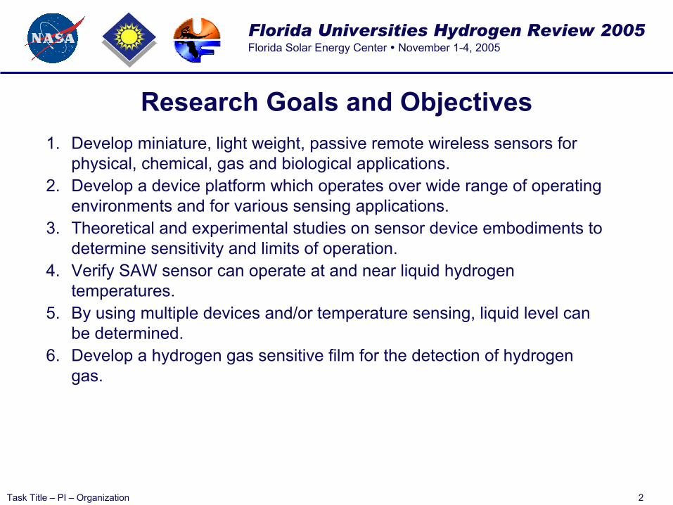
Research Goals and Objectives1. Develop miniature, light weight, passive remote wireless sensors for
physical, chemical, gas and biological applications.2. Develop a device platform which operates over wide range of operating
environments and for various sensing applications.3. Theoretical and experimental studies on sensor device embodiments to
determine sensitivity and limits of operation.4. Verify SAW sensor can operate at and near liquid hydrogen
temperatures.5. By using multiple devices and/or temperature sensing, liquid level can
be determined.6. Develop a hydrogen gas sensitive film for the detection of hydrogen
gas.
Florida Universities Hydrogen Review 2005Florida Solar Energy Center November 1-4, 2005
Task Title – PI – Organization 3
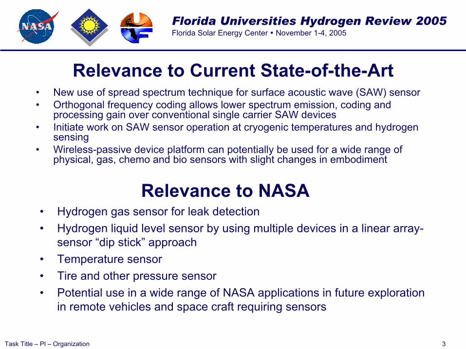
Relevance to Current State-of-the-Art• New use of spread spectrum technique for surface acoustic wave (SAW) sensor• Orthogonal frequency coding allows lower spectrum emission, coding and
processing gain over conventional single carrier SAW devices• Initiate work on SAW sensor operation at cryogenic temperatures and hydrogen
sensing• Wireless-passive device platform can potentially be used for a wide range of
physical, gas, chemo and bio sensors with slight changes in embodiment
Relevance to NASA• Hydrogen gas sensor for leak detection• Hydrogen liquid level sensor by using multiple devices in a linear array-
sensor “dip stick” approach• Temperature sensor• Tire and other pressure sensor• Potential use in a wide range of NASA applications in future exploration
in remote vehicles and space craft requiring sensors

Florida Universities Hydrogen Review 2005Florida Solar Energy Center November 1-4, 2005
Task Title – PI – Organization 4
Budget, Schedule and Deliverables• Start date delay due to contract setup - 1st Year Funding• We are on schedule and within this year’s budget of $90K• Deliverables: Qtrly reports, 3 publications, devices fabricated and
tested
ID Task Name1 Contract Award
2 Project/contract initiation
3 Design Mask 1 Initial testing
4 Fabricate Device #1
5 Measure & Analysis Device #1
6 Design Mask #2 TCD Extraction
7 Fabricate Device #2
8 Measure Device & Analysis #2
9 Design Mask #3 Hydrogen Gas Sensor
10 Fabricate Device #3
11 Measure & Analysis Device #3
12 Antenna Designs and Measurenments
13 Final Report
Jan Feb Mar Apr May Jun Jul Aug Sep Oct Nov Dec
Florida Universities Hydrogen Review 2005Florida Solar Energy Center November 1-4, 2005
Task Title – PI – Organization 5
Anticipated Technology End Use
• Hydrogen gas sensor for leak detection• Hydrogen liquid level sensor by using multiple devices in a linear array-
sensor “dip stick” approach• Temperature sensor• Tire and other pressure sensor• Cement temperature curing monitor using a large array of coded SAW
sensors• Small wireless coded strain/ vibration sensor for moving systems• High temperature remote sensing for turbines or other harsh
environment applications• Bio- and Chemo- sensors can use the current and future progress of
other investigators working in the field since the device platform and interrogation system will be developed

Florida Universities Hydrogen Review 2005Florida Solar Energy Center November 1-4, 2005
Task Title – PI – Organization 6
Accomplishments and Results• Demonstrated low temperature operation of SAW OFC Sensor• Designed and fabricated a 500 MHz OFC SAW sensor with
approximately 1um lines using pattern generator• Designed and are attempting fabrication of .7 um, 1 GHz SAW OFC
sensor using ebeam writer– on third iteration of fabrication• Theory and experiments on SAW reflectivity to account for film
thickness and line width vs. period variation• Expanded interrogation system software and analysis for device
evaluation• Expand analysis and design software, including a 2-D coupling of
modes model which allows weighted reflector analysis• Built several OFC hydrogen gas sensors using palladium thin films and
begun characterization• Initial experiments using the FSEC color changing thin films for
integration into OFC sensor devices for detecting hydrogen• Initial cryogenic temperature testing of LiNbO3 substrates

Florida Universities Hydrogen Review 2005Florida Solar Energy Center November 1-4, 2005
Task Title – PI – Organization 7
Linear Stepped Chirp Time
Response with 7 Chips
0 0.2 0.4 0.6 0.8 1 1.2 1.4 1.6 1.80
0.2
0.4
0.6
0.8
Normalized Frequency
0 1 2 3 4 5 6 71
0.5
0
0.5
1
Normalized Time (Chip Lengths)
Basis of Operation
Florida Universities Hydrogen Review 2005Florida Solar Energy Center November 1-4, 2005
Task Title – PI – Organization 8
0 0.2 0.4 0.6 0.8 1 1.2 1.4 1.6 1.80
0.2
0.4
0.6
0.8
Normalized Frequency
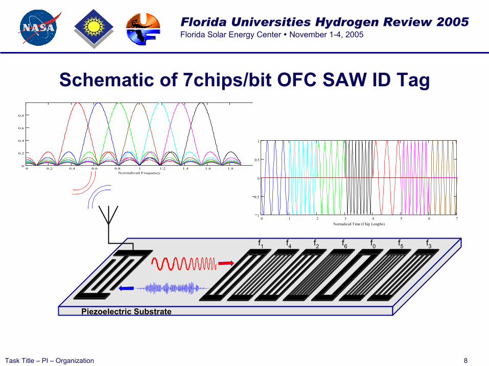
Schematic of 7chips/bit OFC SAW ID Tag
0 1 2 3 4 5 6 71
0.5
0
0.5
1
Normalized Time (Chip Lengths)
Piezoelectric Substrate
f1 f4 f6 f0f2 f5 f3
Florida Universities Hydrogen Review 2005Florida Solar Energy Center November 1-4, 2005
Task Title – PI – Organization 9
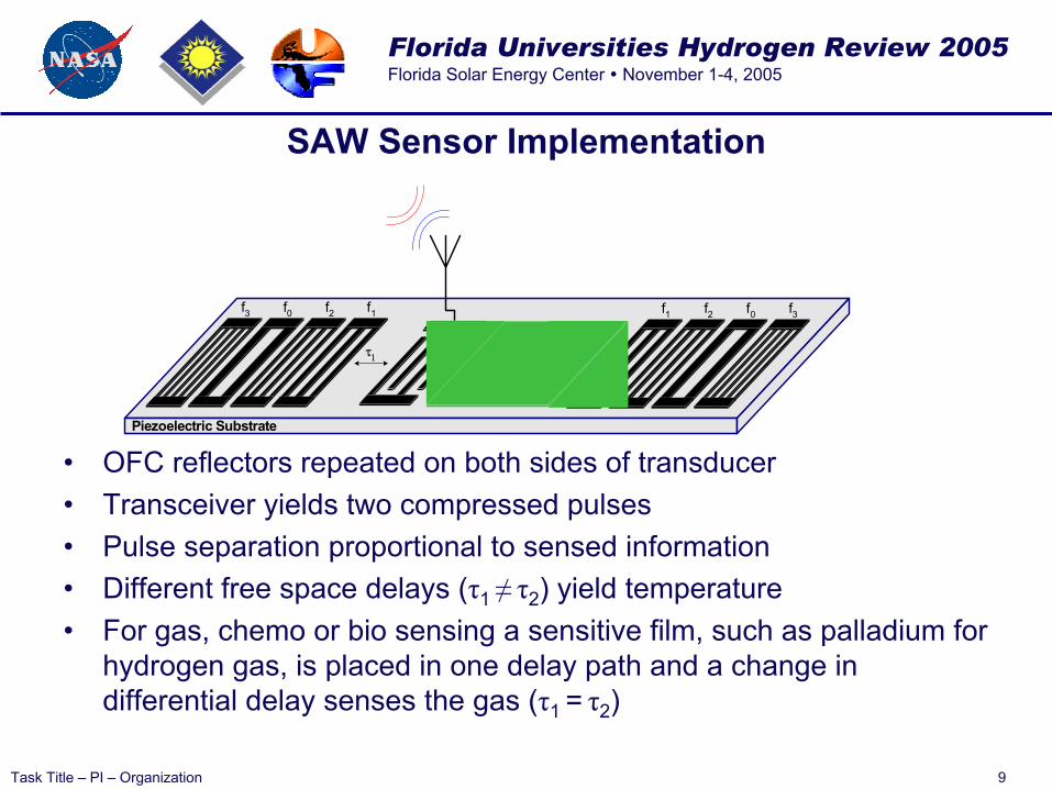
SAW Sensor Implementation
• OFC reflectors repeated on both sides of transducer• Transceiver yields two compressed pulses• Pulse separation proportional to sensed information• Different free space delays (τ1 ≠ τ2) yield temperature• For gas, chemo or bio sensing a sensitive film, such as palladium for
hydrogen gas, is placed in one delay path and a change in differential delay senses the gas (τ1 = τ2)
Piezoelectric Substrate
f1 f0f2 f3f1f0 f2f3
τ1 τ2
Florida Universities Hydrogen Review 2005Florida Solar Energy Center November 1-4, 2005
Task Title – PI – Organization 10
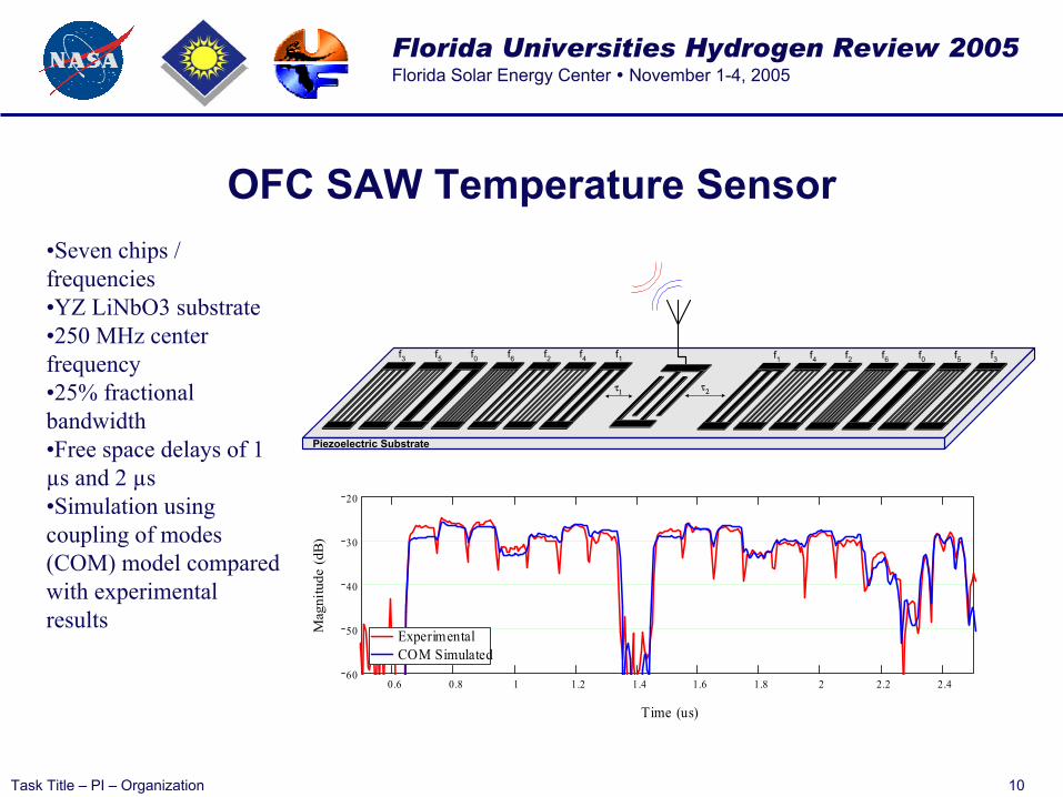
OFC SAW Temperature Sensor
Piezoelectric Substrate
f1 f4 f6 f0f2 f5 f3f1f4f6f0 f2f5f3
τ1 τ2
0.6 0.8 1 1.2 1.4 1.6 1.8 2 2.2 2.460
50
40
30
20
ExperimentalCOM Simulated
Time (us)
Mag
nitu
de (
dB)
•Seven chips / frequencies•YZ LiNbO3 substrate•250 MHz center frequency•25% fractional bandwidth•Free space delays of 1 µs and 2 µs•Simulation using coupling of modes (COM) model compared with experimental results
Florida Universities Hydrogen Review 2005Florida Solar Energy Center November 1-4, 2005
Task Title – PI – Organization 11
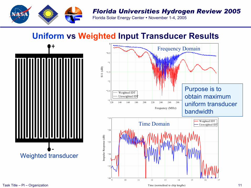
Uniform vs Weighted Input Transducer Results
9 10 11 12 13 14 15 16 1740
35
30
25
20
15Weighted IDTUnweighted IDT
Time (normalized to chip lengths)
Impu
lse
Res
pons
e (d
B)
120 140 160 180 200 220 240 260 280 300 320 340 360 3803
2.5
2
1.5
1
0.5
0
Weighted IDTUnweighted IDT
Frequency (MHz)
S11
(dB
)
Purpose is to obtain maximum uniform transducer bandwidth
Weighted transducer
Time Domain
Frequency Domain
Florida Universities Hydrogen Review 2005Florida Solar Energy Center November 1-4, 2005
Task Title – PI – Organization 12
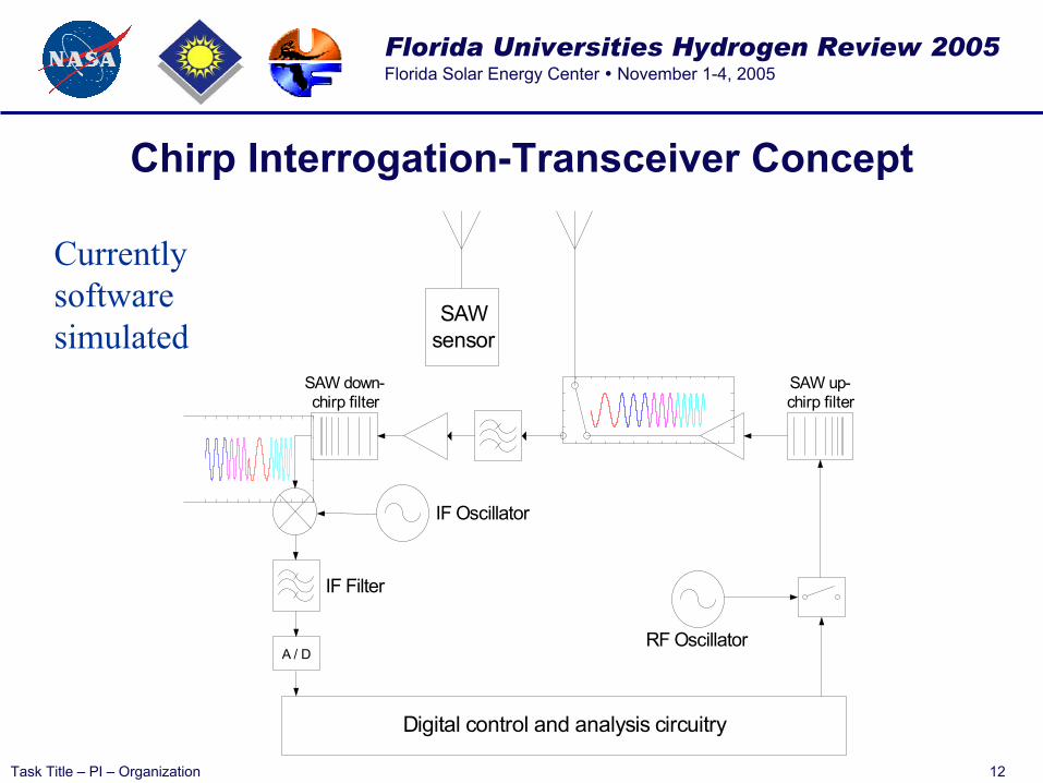
Chirp Interrogation-Transceiver Concept
SAWsensor
RF Oscillator
Digital control and analysis circuitry
SAW up-chirp filter
SAW down-chirp filter
IF Oscillator
A / D
IF Filter
Currently software simulated

Florida Universities Hydrogen Review 2005Florida Solar Energy Center November 1-4, 2005
Task Title – PI – Organization 13
Bit, PN, OFC Signal Comparison
0 0.2 0.4 0.6 0.8 1 1.2 1.4 1.6 1.8 2-40
-35
-30
-25
-20
-15
-10
-5
0
Normalized FrequencyNormalized to Peak of Single Carrier (dB)
7 chips/bit PN-OFC7 chips/bit PN Single CarrierBPSK
0 1 2 3 4 5 6 70
0.2
0.4
0.6
0.8
1
Time Normalized to a Chip Length
Normalized A
mplitude
7 chips/bit PN-OFC7 chips/bit PN Single CarrierBPSK
Matched Filter Correlated Response
BPSK –no coding
PN Code
OFC Code
Florida Universities Hydrogen Review 2005Florida Solar Energy Center November 1-4, 2005
Task Title – PI – Organization 14
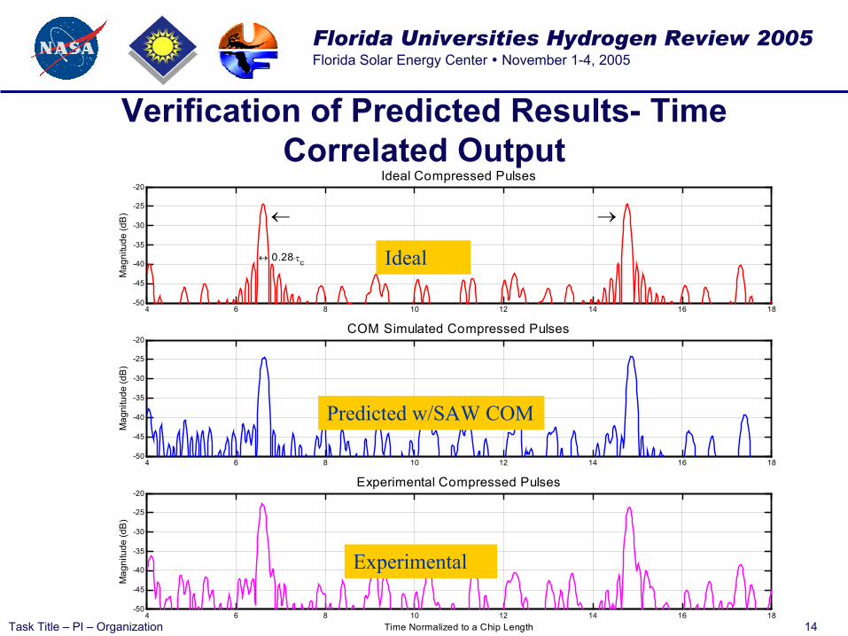
Verification of Predicted Results- Time Correlated Output
4 6 8 10 12 14 16 18-50
-45
-40
-35
-30
-25
-20
← →
↔ 0.28⋅τc
Mag
nitu
de (d
B)
Ideal Compressed Pulses
4 6 8 10 12 14 16 18-50
-45
-40
-35
-30
-25
-20
Mag
nitu
de (d
B)
COM Simulated Compressed Pulses
4 6 8 10 12 14 16 18-50
-45
-40
-35
-30
-25
-20
Time Normalized to a Chip Length
Mag
nitu
de (d
B)
Experimental Compressed Pulses
Ideal
Predicted w/SAW COM
Experimental

Florida Universities Hydrogen Review 2005Florida Solar Energy Center November 1-4, 2005
Task Title – PI – Organization 15
Measured Time Correlated Output Compressed Pulse Responses
versus Temperature
Single temperature measurement showing the 2 compressed pulses and differential delay
Florida Universities Hydrogen Review 2005Florida Solar Energy Center November 1-4, 2005
Task Title – PI – Organization 16
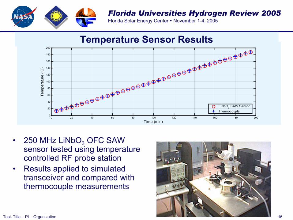
• 250 MHz LiNbO3 OFC SAW sensor tested using temperature controlled RF probe station
• Results applied to simulated transceiver and compared with thermocouple measurements
0 20 40 60 80 100 120 140 160 180 2000
20
40
60
80
100
120
140
160
180
200Temperature Sensor Results
Time (min)
Tem
pera
ture
( °C
)
LiNbO3 SAW SensorThermocouple
Temperature Sensor Results

Florida Universities Hydrogen Review 2005Florida Solar Energy Center November 1-4, 2005
Task Title – PI – Organization 17
Cryogenic Sensor Results
• SAW device feasibility is established• Initial device design, fabrication and
testing completed at liquid nitrogen temperatures
– Device performed over multiple temperature cycling
– Initial temperature coefficient of delay (TCD) obtained
– Using TCD, temperature is predicted and compared to measurement (graph)
0 5 10 15 20 25-200
-150
-100
-50
0
50
Time (min)
Temperature (°C)
ThermocoupleLiNbO3 SAW SensorScale
Vertical: +90 to -200 oCHorizontal: Relative
time (min)
Measurement system with liquid nitrogen Dewar and vacuum chamber with DUT

Florida Universities Hydrogen Review 2005Florida Solar Energy Center November 1-4, 2005
Task Title – PI – Organization 18
Device Fabrication Progresspush to higher frequencies to reduce
antenna size and improve performance
1GHz (0.75 um lines)
1.27 um line resolved in positive PR on mask plate using PG shows good line definition
1.5GHz (.5um lines)
1 um lines after lift off using +ve PR (S1813) by direct on wafer write using Image Repeater, (lines are jagged, lift off needs optimization)
E-beamPattern generator should take us to .7um lines while Ebeam should yield .5 um lines
Lines look like “spaghetti” due to poor adhesion in liftoff processing

Florida Universities Hydrogen Review 2005Florida Solar Energy Center November 1-4, 2005
Task Title – PI – Organization 19
Wireless Testing of a 500 MHz Sensor
• Simple dipole antenna for wireless transmission• Demonstrated Tx/Rx at a distance of 2 feet
350 400 450 500 550 600 650-1.6
-1.4
-1.2
-1
-0.8
-0.6
-0.4
-0.2
0
Frequency (MHz)
dB(S
11)
predictedexprimental
Experimental and COM Predicted 500 MHz sensors
0.2 0.4 0.6 0.8 1 1.2
-200
-180
-160
-140
-120
-100
-80
S11 Time Domain Response
Time (µs)
S11
(Im
puls
e R
espo
nse)
predictedexprimental
Florida Universities Hydrogen Review 2005Florida Solar Energy Center November 1-4, 2005
Task Title – PI – Organization 20
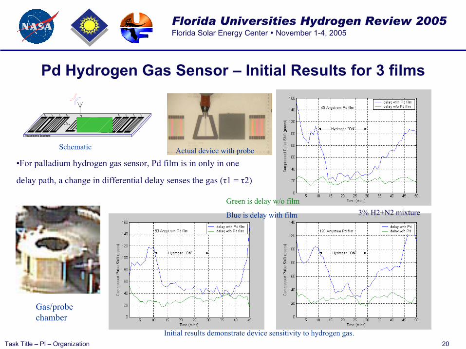
Pd Hydrogen Gas Sensor – Initial Results for 3 films
Piezoelectric Substrate
f1 f0f2 f3f1f0 f2f3
τ1 τ2
•For palladium hydrogen gas sensor, Pd film is in only in one
delay path, a change in differential delay senses the gas (τ1 = τ2)
Gas/probe chamber
Schematic Actual device with probe
Initial results demonstrate device sensitivity to hydrogen gas.
Green is delay w/o film
Blue is delay with film 3% H2+N2 mixture
Florida Universities Hydrogen Review 2005Florida Solar Energy Center November 1-4, 2005
Task Title – PI – Organization 21
Future Plans• Fabricate and build a 1 GHz SAW OFC sensor to reduce size and
optimize performance• Build or purchase a cryostat for sensor testing at liquid hydrogen
temperatures and build a cryogenic data acquisition system for device testing
• Continue hydrogen gas sensor development using metal and/or oxide thin films and continue application of the FSEC films. Materials evaluation work will need to be conducted to understand the film and SAW interaction
• Analysis, design and fabrication of an interrogation/receiver system for “pinging” the OFC sensor and extracting the received data
• Design antenna and device to optimize performance• Investigate parallel track embodiments to relax fractional bandwidth
requirements of the antenna• Goal is to have a fully operational proof-of-concept, multi-sensor SAW
OFC system within approximately the next 18 months, for hydrogenliquid and gas sensing