Embed Size (px)
Citation preview
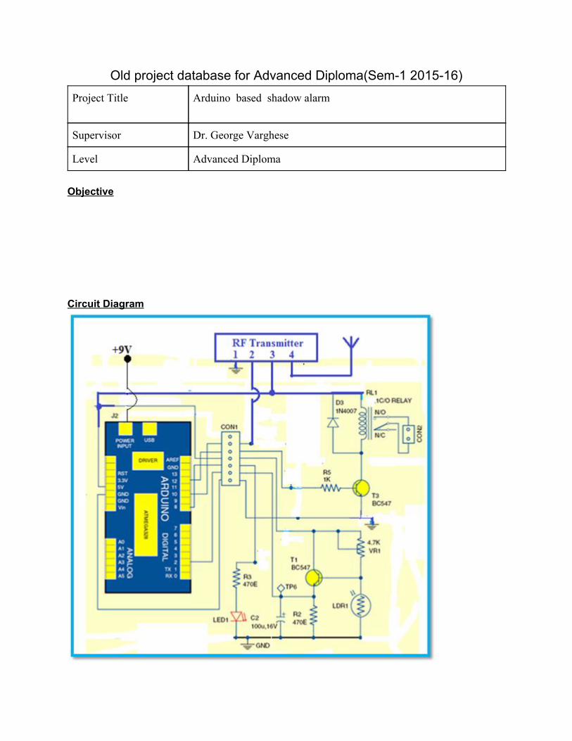
Old project database for Advanced Diploma(Sem-1 2015-16) Project Title Arduino based shadow alarm
Supervisor Dr. George Varghese
Level Advanced Diploma Objective Circuit Diagram
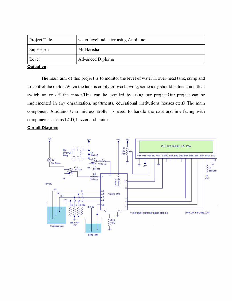
Project Title water level indicator using Aurduino
Supervisor Mr.Harisha
Level Advanced Diploma Objective
The main aim of this project is to monitor the level of water in over-head tank, sump and
to control the motor .When the tank is empty or overflowing, somebody should notice it and then
switch on or off the motor.This can be avoided by using our project.Our project can be
implemented in any organization, apartments, educational institutions houses etc.Ø The main
component Aurduino Uno microcontroller is used to handle the data and interfacing with
components such as LCD, buzzer and motor.
Circuit Diagram
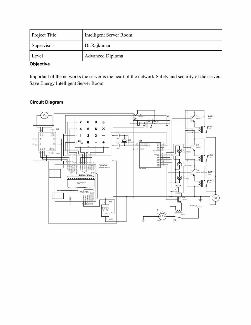
Project Title Intelligent Server Room
Supervisor Dr.Rajkumar
Level Advanced Diploma Objective Important of the networks the server is the heart of the network-Safety and security of the servers Save Energy Intelligent Server Room Circuit Diagram
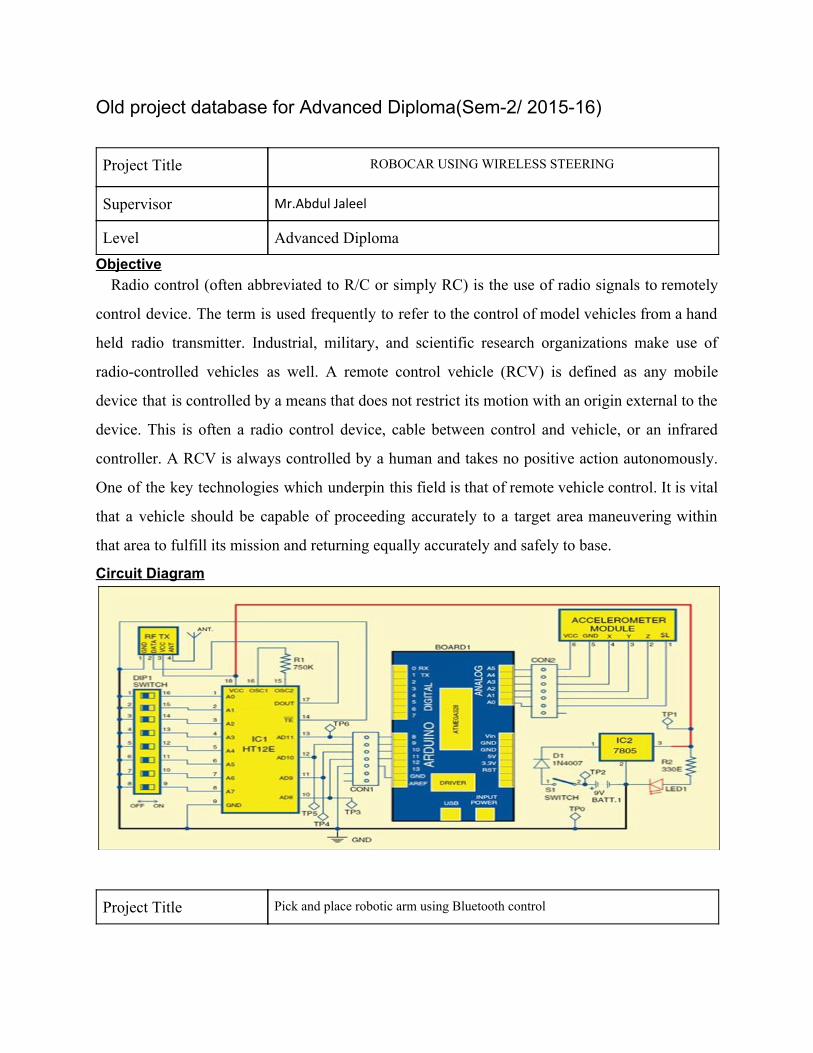
Old project database for Advanced Diploma(Sem-2/ 2015-16) Project Title ROBOCAR USING WIRELESS STEERING
Supervisor Mr.Abdul Jaleel
Level Advanced Diploma Objective
Radio control (often abbreviated to R/C or simply RC) is the use of radio signals to remotely
control device. The term is used frequently to refer to the control of model vehicles from a hand
held radio transmitter. Industrial, military, and scientific research organizations make use of
radio-controlled vehicles as well. A remote control vehicle (RCV) is defined as any mobile
device that is controlled by a means that does not restrict its motion with an origin external to the
device. This is often a radio control device, cable between control and vehicle, or an infrared
controller. A RCV is always controlled by a human and takes no positive action autonomously.
One of the key technologies which underpin this field is that of remote vehicle control. It is vital
that a vehicle should be capable of proceeding accurately to a target area maneuvering within
that area to fulfill its mission and returning equally accurately and safely to base.
Circuit Diagram
Project Title Pick and place robotic arm using Bluetooth control
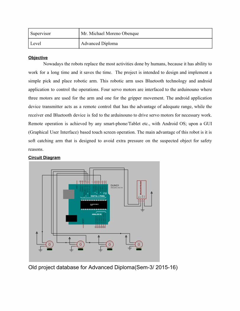
Supervisor Mr. Michael Moreno Obenque
Level Advanced Diploma
Objective
Nowadays the robots replace the most activities done by humans, because it has ability to
work for a long time and it saves the time. The project is intended to design and implement a
simple pick and place robotic arm. This robotic arm uses Bluetooth technology and android
application to control the operations. Four servo motors are interfaced to the arduinouno where
three motors are used for the arm and one for the gripper movement. The android application
device transmitter acts as a remote control that has the advantage of adequate range, while the
receiver end Bluetooth device is fed to the arduinouno to drive servo motors for necessary work.
Remote operation is achieved by any smart-phone/Tablet etc., with Android OS; upon a GUI
(Graphical User Interface) based touch screen operation. The main advantage of this robot is it is
soft catching arm that is designed to avoid extra pressure on the suspected object for safety
reasons.
Circuit Diagram
Old project database for Advanced Diploma(Sem-3/ 2015-16)
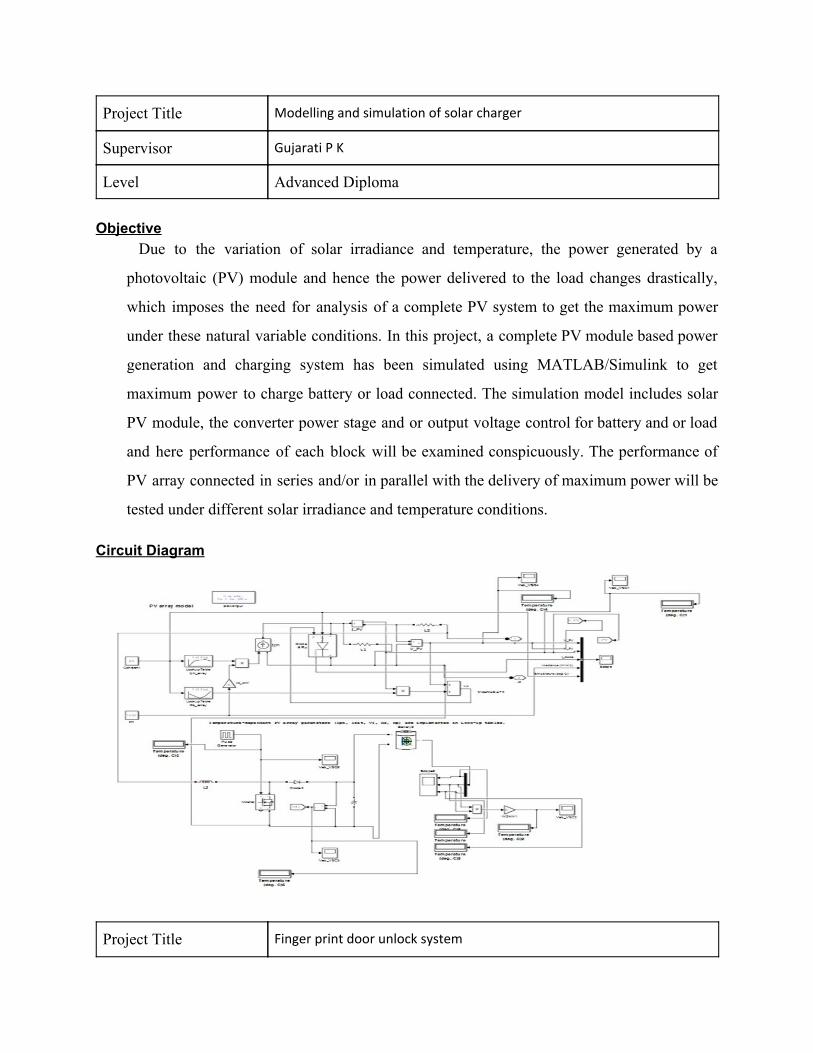
Project Title Modelling and simulation of solar charger
Supervisor Gujarati P K
Level Advanced Diploma Objective
Due to the variation of solar irradiance and temperature, the power generated by a
photovoltaic (PV) module and hence the power delivered to the load changes drastically,
which imposes the need for analysis of a complete PV system to get the maximum power
under these natural variable conditions. In this project, a complete PV module based power
generation and charging system has been simulated using MATLAB/Simulink to get
maximum power to charge battery or load connected. The simulation model includes solar
PV module, the converter power stage and or output voltage control for battery and or load
and here performance of each block will be examined conspicuously. The performance of
PV array connected in series and/or in parallel with the delivery of maximum power will be
tested under different solar irradiance and temperature conditions.
Circuit Diagram
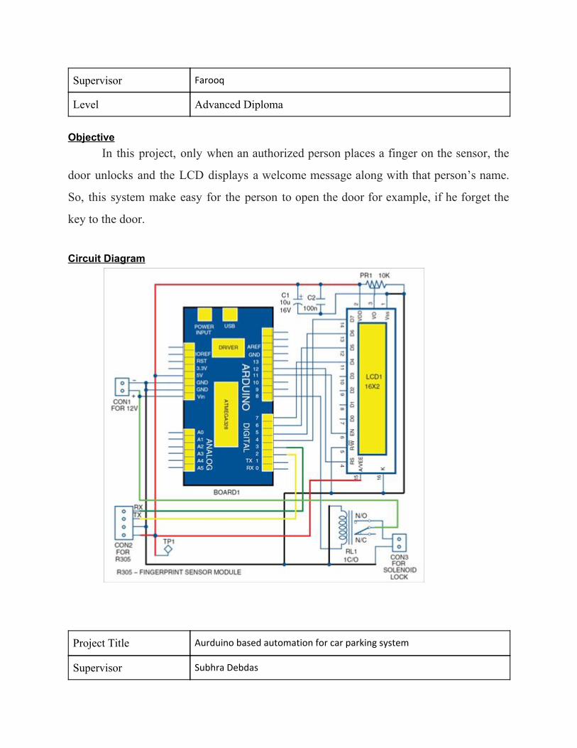
Project Title Finger print door unlock system
Supervisor Farooq
Level Advanced Diploma Objective
In this project, only when an authorized person places a finger on the sensor, the
door unlocks and the LCD displays a welcome message along with that person’s name.
So, this system make easy for the person to open the door for example, if he forget the
key to the door.
Circuit Diagram
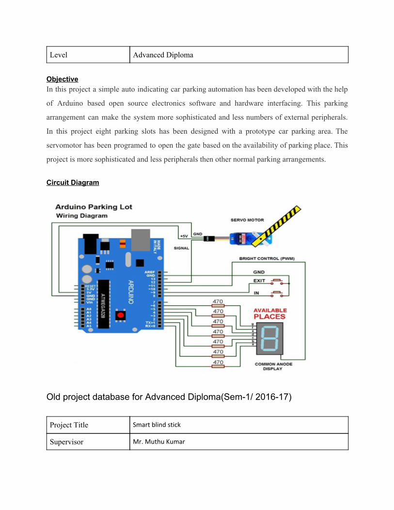
Project Title Aurduino based automation for car parking system
Supervisor Subhra Debdas
Level Advanced Diploma
Objective In this project a simple auto indicating car parking automation has been developed with the help
of Arduino based open source electronics software and hardware interfacing. This parking
arrangement can make the system more sophisticated and less numbers of external peripherals.
In this project eight parking slots has been designed with a prototype car parking area. The
servomotor has been programed to open the gate based on the availability of parking place. This
project is more sophisticated and less peripherals then other normal parking arrangements.
Circuit Diagram
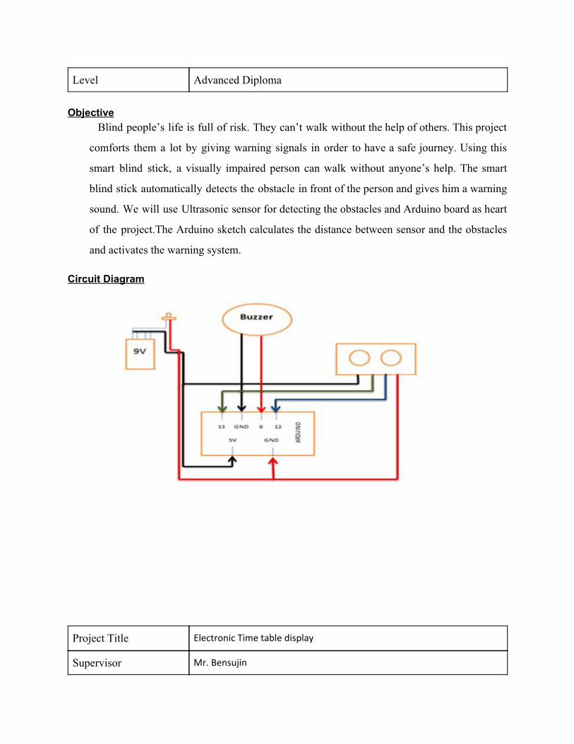
Old project database for Advanced Diploma(Sem-1/ 2016-17) Project Title Smart blind stick
Supervisor Mr. Muthu Kumar
Level Advanced Diploma Objective
Blind people’s life is full of risk. They can’t walk without the help of others. This project
comforts them a lot by giving warning signals in order to have a safe journey. Using this
smart blind stick, a visually impaired person can walk without anyone’s help. The smart
blind stick automatically detects the obstacle in front of the person and gives him a warning
sound. We will use Ultrasonic sensor for detecting the obstacles and Arduino board as heart
of the project.The Arduino sketch calculates the distance between sensor and the obstacles
and activates the warning system.
Circuit Diagram
Project Title Electronic Time table display
Supervisor Mr. Bensujin
Level Advanced Diploma
Objective
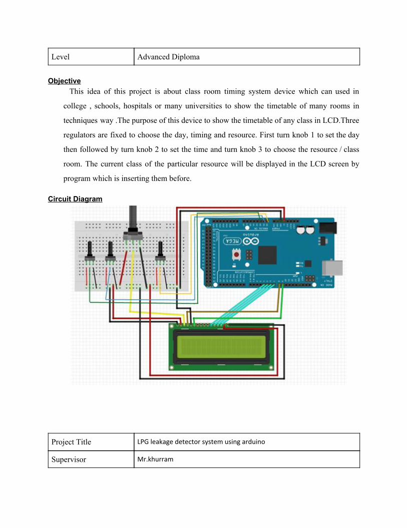
This idea of this project is about class room timing system device which can used in
college , schools, hospitals or many universities to show the timetable of many rooms in
techniques way .The purpose of this device to show the timetable of any class in LCD.Three
regulators are fixed to choose the day, timing and resource. First turn knob 1 to set the day
then followed by turn knob 2 to set the time and turn knob 3 to choose the resource / class
room. The current class of the particular resource will be displayed in the LCD screen by
program which is inserting them before.
Circuit Diagram
Project Title LPG leakage detector system using arduino
Supervisor Mr.khurram
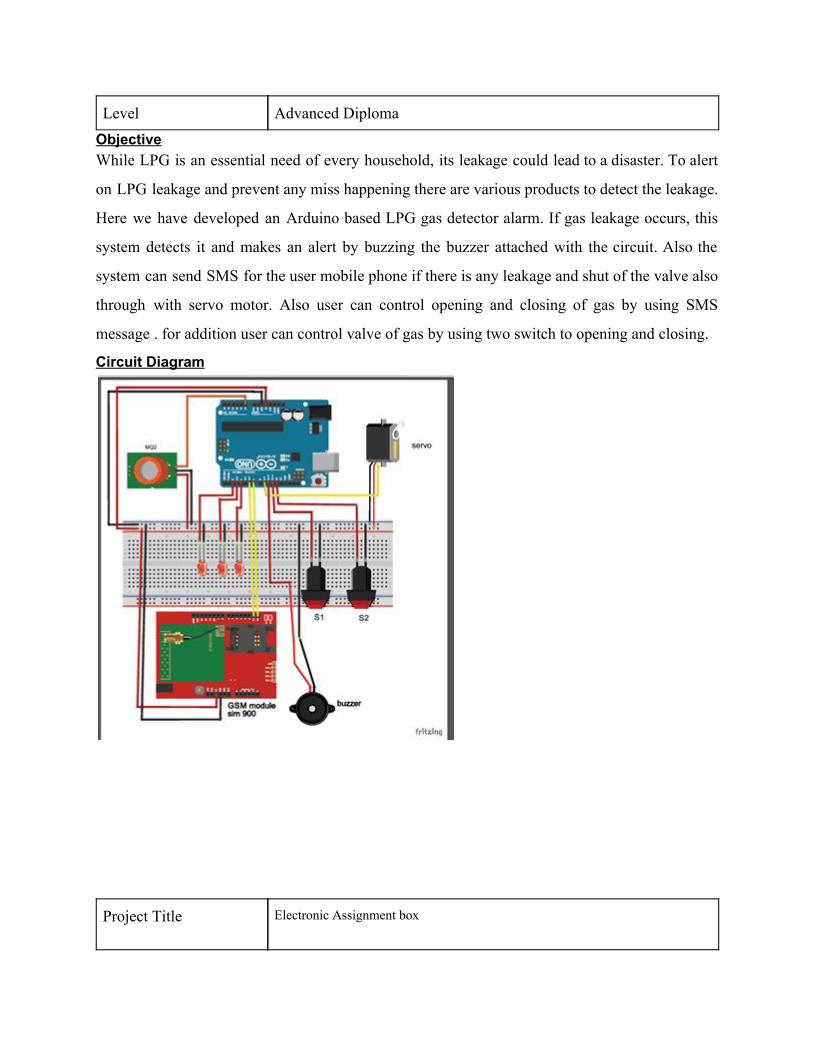
Level Advanced Diploma Objective While LPG is an essential need of every household, its leakage could lead to a disaster. To alert
on LPG leakage and prevent any miss happening there are various products to detect the leakage.
Here we have developed an Arduino based LPG gas detector alarm. If gas leakage occurs, this
system detects it and makes an alert by buzzing the buzzer attached with the circuit. Also the
system can send SMS for the user mobile phone if there is any leakage and shut of the valve also
through with servo motor. Also user can control opening and closing of gas by using SMS
message . for addition user can control valve of gas by using two switch to opening and closing.
Circuit Diagram
Project Title Electronic Assignment box
Supervisor Mr.Bensujin
Level Advanced Diploma
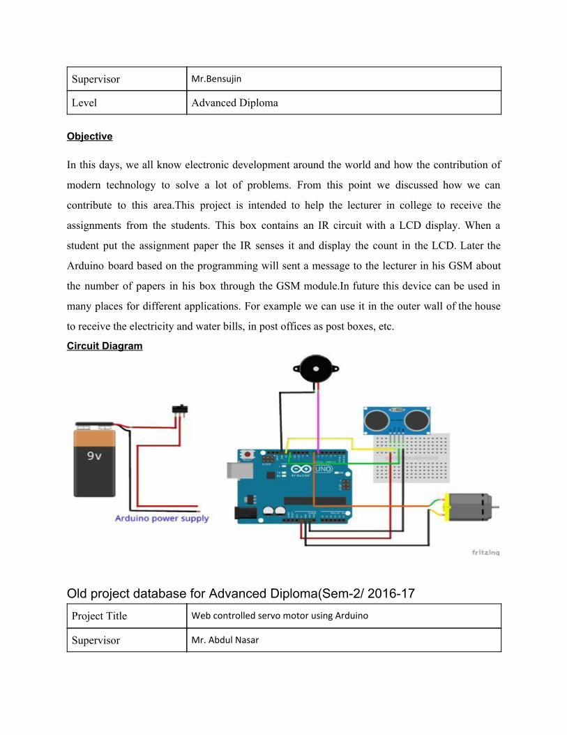
Objective In this days, we all know electronic development around the world and how the contribution of
modern technology to solve a lot of problems. From this point we discussed how we can
contribute to this area.This project is intended to help the lecturer in college to receive the
assignments from the students. This box contains an IR circuit with a LCD display. When a
student put the assignment paper the IR senses it and display the count in the LCD. Later the
Arduino board based on the programming will sent a message to the lecturer in his GSM about
the number of papers in his box through the GSM module.In future this device can be used in
many places for different applications. For example we can use it in the outer wall of the house
to receive the electricity and water bills, in post offices as post boxes, etc.
Circuit Diagram
Old project database for Advanced Diploma(Sem-2/ 2016-17 Project Title Web controlled servo motor using Arduino
Supervisor Mr. Abdul Nasar
Level Advanced Diploma
Objective
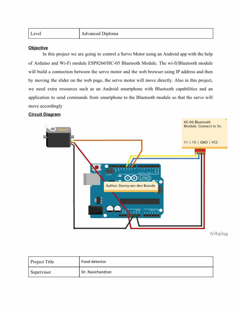
In this project we are going to control a Servo Motor using an Android app with the help
of Arduino and Wi-Fi module ESP8266/HC-05 Bluetooth Module. The wi-fi/Bluetooth module
will build a connection between the servo motor and the web browser using IP address and then
by moving the slider on the web page, the servo motor will move directly. Also in this project,
we need extra resources such as an Android smartphone with Bluetooth capabilities and an
application to send commands from smartphone to the Bluetooth module so that the servo will
move accordingly
Circuit Diagram
Project Title Food detector
Supervisor Dr. Ravichandran
Level Advanced Diploma Objective
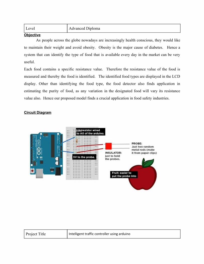
As people across the globe nowadays are increasingly health conscious, they would like
to maintain their weight and avoid obesity. Obesity is the major cause of diabetes. Hence a
system that can identify the type of food that is available every day in the market can be very
useful.
Each food contains a specific resistance value. Therefore the resistance value of the food is
measured and thereby the food is identified. The identified food types are displayed in the LCD
display. Other than identifying the food type, the food detector also finds application in
estimating the purity of food, as any variation in the designated food will vary its resistance
value also. Hence our proposed model finds a crucial application in food safety industries.
Circuit Diagram
Project Title Intelligent traffic controller using arduino
Supervisor Mr. Murali
Level Advanced Diploma Objective
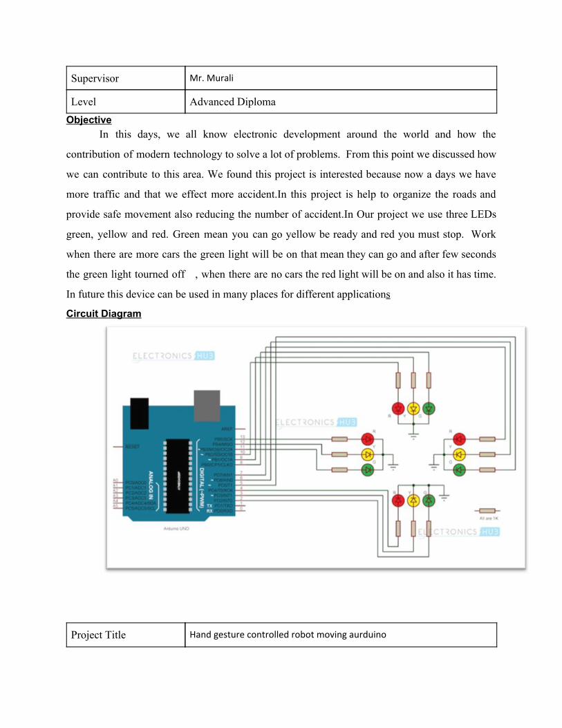
In this days, we all know electronic development around the world and how the
contribution of modern technology to solve a lot of problems. From this point we discussed how
we can contribute to this area. We found this project is interested because now a days we have
more traffic and that we effect more accident.In this project is help to organize the roads and
provide safe movement also reducing the number of accident.In Our project we use three LEDs
green, yellow and red. Green mean you can go yellow be ready and red you must stop. Work
when there are more cars the green light will be on that mean they can go and after few seconds
the green light tourned off , when there are no cars the red light will be on and also it has time.
In future this device can be used in many places for different applications
Circuit Diagram
Project Title Hand gesture controlled robot moving aurduino
Supervisor Dr. George Varghees
Level Advanced Diploma
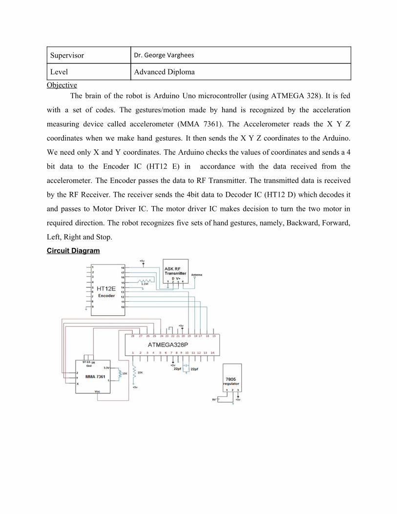
Objective The brain of the robot is Arduino Uno microcontroller (using ATMEGA 328). It is fed
with a set of codes. The gestures/motion made by hand is recognized by the acceleration
measuring device called accelerometer (MMA 7361). The Accelerometer reads the X Y Z
coordinates when we make hand gestures. It then sends the X Y Z coordinates to the Arduino.
We need only X and Y coordinates. The Arduino checks the values of coordinates and sends a 4
bit data to the Encoder IC (HT12 E) in accordance with the data received from the
accelerometer. The Encoder passes the data to RF Transmitter. The transmitted data is received
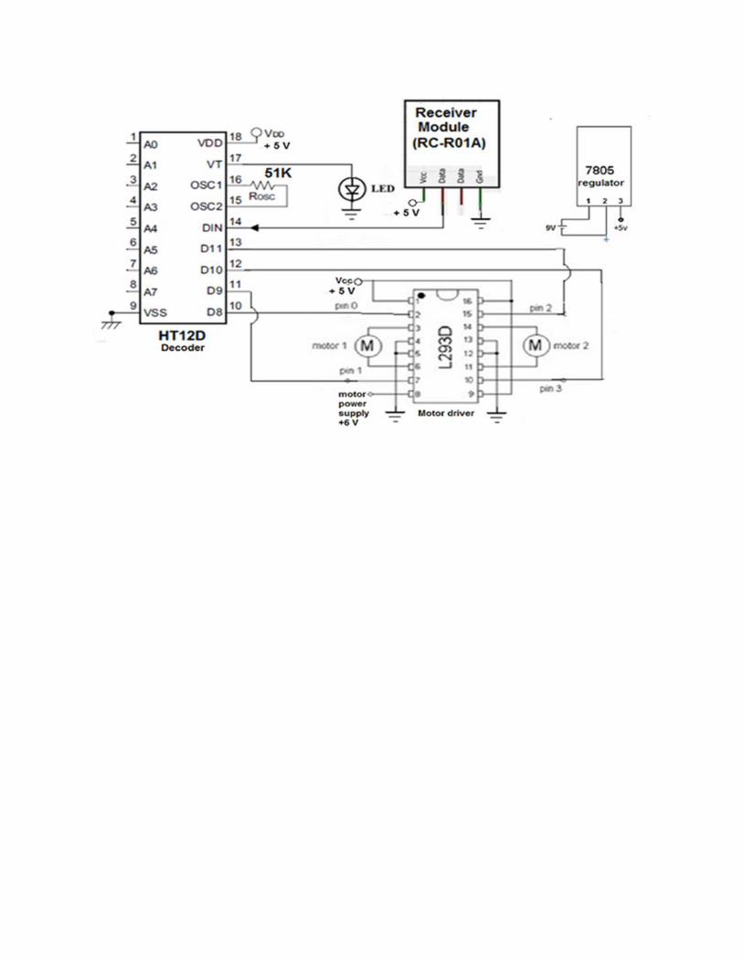
by the RF Receiver. The receiver sends the 4bit data to Decoder IC (HT12 D) which decodes it
and passes to Motor Driver IC. The motor driver IC makes decision to turn the two motor in
required direction. The robot recognizes five sets of hand gestures, namely, Backward, Forward,
Left, Right and Stop.
Circuit Diagram
OLD PROJECT DATA BASE FOR B.TECH(SEM-3/ 2015-16)
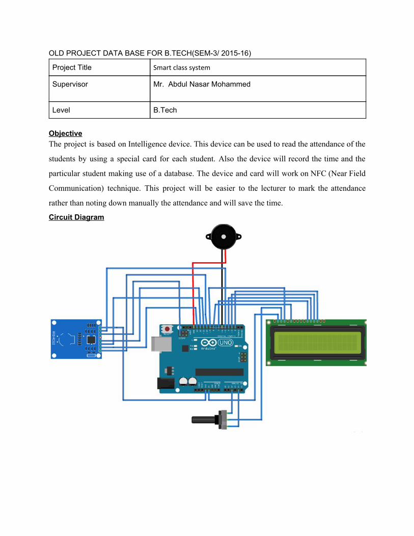
Project Title Smart class system
Supervisor Mr. Abdul Nasar Mohammed
Level B.Tech
Objective The project is based on Intelligence device. This device can be used to read the attendance of the
students by using a special card for each student. Also the device will record the time and the
particular student making use of a database. The device and card will work on NFC (Near Field
Communication) technique. This project will be easier to the lecturer to mark the attendance
rather than noting down manually the attendance and will save the time.
Circuit Diagram
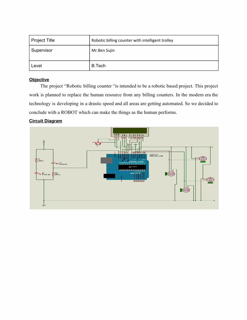
Project Title Robotic billing counter with intelligent trolley
Supervisor Mr.Ben Sujin
Level B.Tech
Objective
The project “Robotic billing counter “is intended to be a robotic based project. This project
work is planned to replace the human resource from any billing counters. In the modern era the
technology is developing in a drastic speed and all areas are getting automated. So we decided to
conclude with a ROBOT which can make the things as the human performs.
Circuit Diagram
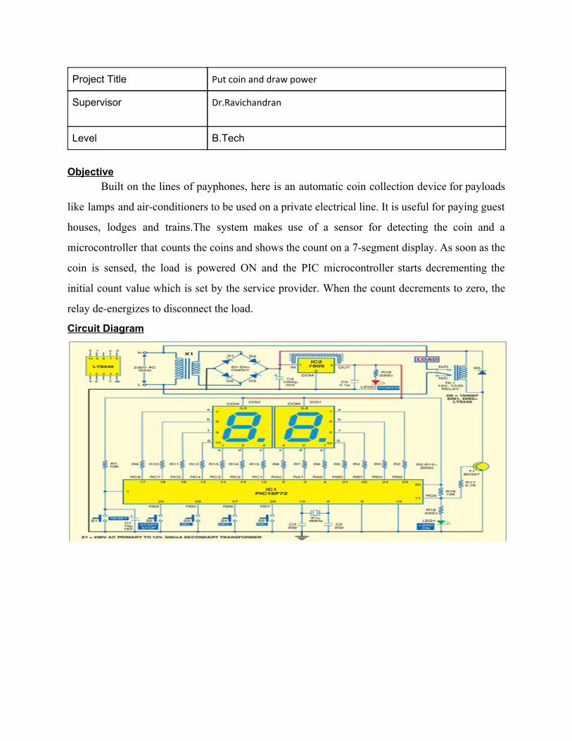
Project Title Put coin and draw power
Supervisor Dr.Ravichandran
Level B.Tech
Objective
Built on the lines of payphones, here is an automatic coin collection device for payloads
like lamps and air-conditioners to be used on a private electrical line. It is useful for paying guest
houses, lodges and trains.The system makes use of a sensor for detecting the coin and a
microcontroller that counts the coins and shows the count on a 7-segment display. As soon as the
coin is sensed, the load is powered ON and the PIC microcontroller starts decrementing the
initial count value which is set by the service provider. When the count decrements to zero, the
relay de-energizes to disconnect the load.
Circuit Diagram
OLD PROJECT DATA BASE FOR B.TECH(SEM-1/ 2016-17)
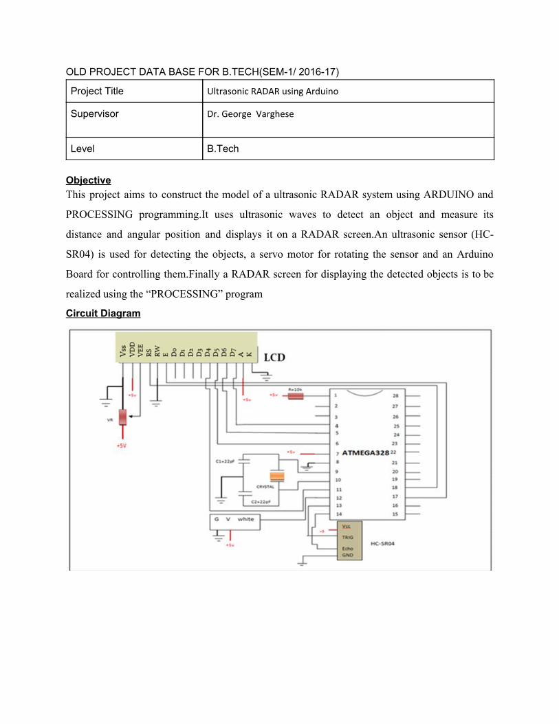
Project Title Ultrasonic RADAR using Arduino
Supervisor Dr. George Varghese
Level B.Tech
Objective This project aims to construct the model of a ultrasonic RADAR system using ARDUINO and
PROCESSING programming.It uses ultrasonic waves to detect an object and measure its
distance and angular position and displays it on a RADAR screen.An ultrasonic sensor (HC-
SR04) is used for detecting the objects, a servo motor for rotating the sensor and an Arduino
Board for controlling them.Finally a RADAR screen for displaying the detected objects is to be
realized using the “PROCESSING” program
Circuit Diagram
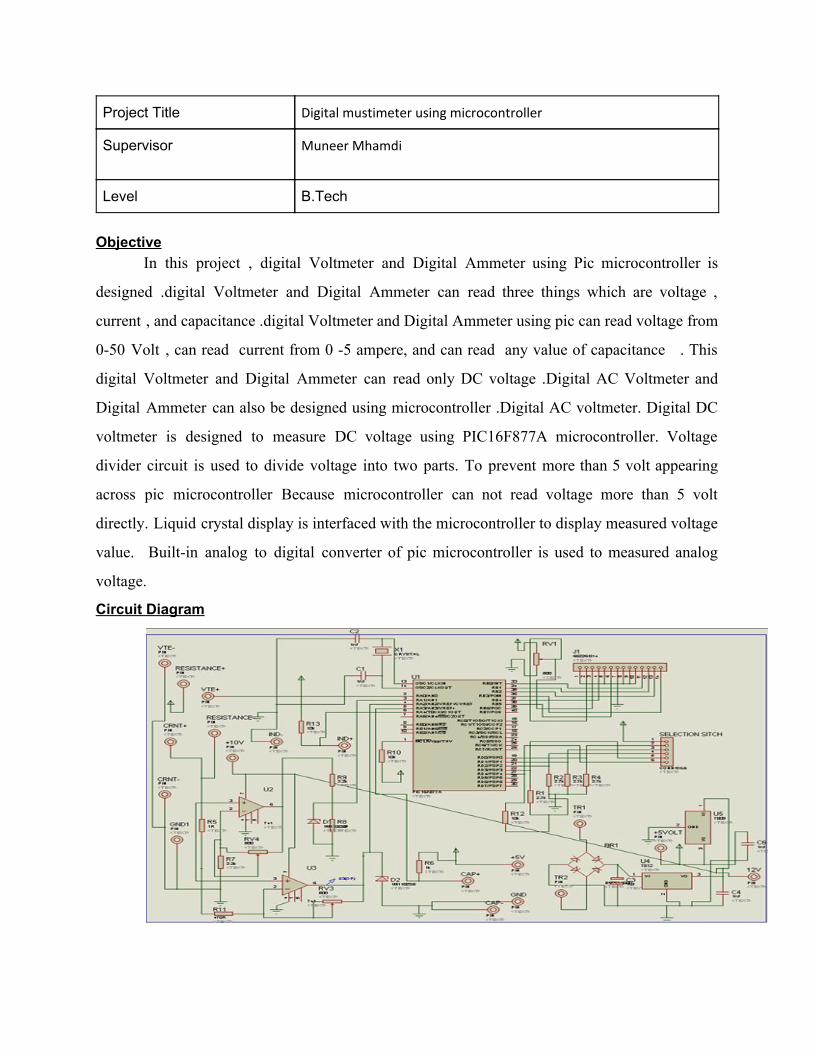
Project Title Digital mustimeter using microcontroller
Supervisor Muneer Mhamdi
Level B.Tech
Objective
In this project , digital Voltmeter and Digital Ammeter using Pic microcontroller is
designed .digital Voltmeter and Digital Ammeter can read three things which are voltage ,
current , and capacitance .digital Voltmeter and Digital Ammeter using pic can read voltage from
0-50 Volt , can read current from 0 -5 ampere, and can read any value of capacitance . This
digital Voltmeter and Digital Ammeter can read only DC voltage .Digital AC Voltmeter and
Digital Ammeter can also be designed using microcontroller .Digital AC voltmeter. Digital DC
voltmeter is designed to measure DC voltage using PIC16F877A microcontroller. Voltage
divider circuit is used to divide voltage into two parts. To prevent more than 5 volt appearing
across pic microcontroller Because microcontroller can not read voltage more than 5 volt
directly. Liquid crystal display is interfaced with the microcontroller to display measured voltage
value. Built-in analog to digital converter of pic microcontroller is used to measured analog
voltage.
Circuit Diagram
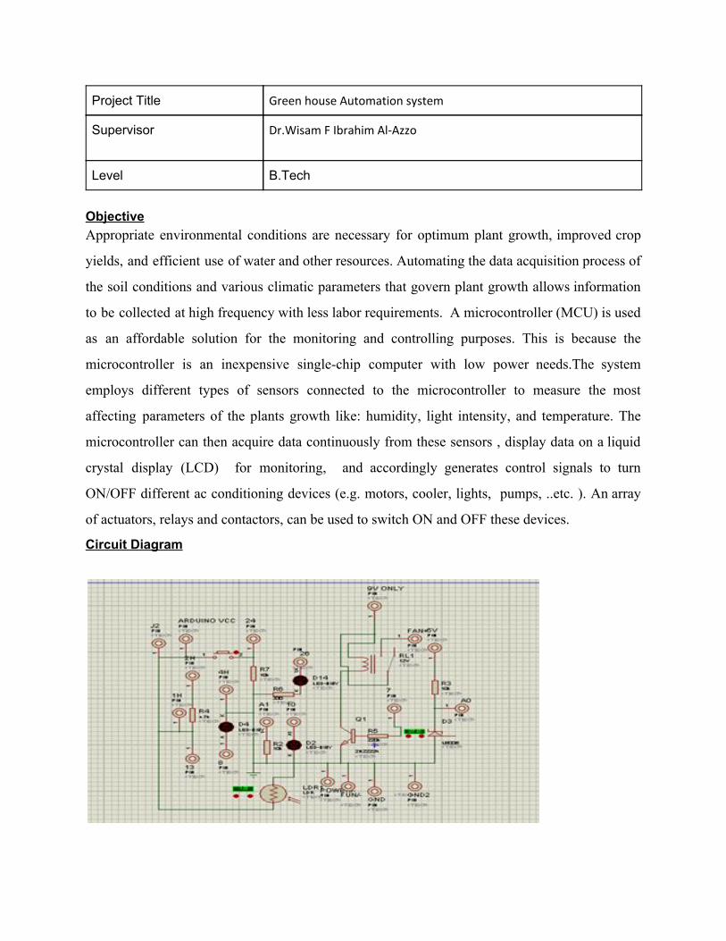
Project Title Green house Automation system
Supervisor Dr.Wisam F Ibrahim Al-Azzo
Level B.Tech
Objective Appropriate environmental conditions are necessary for optimum plant growth, improved crop
yields, and efficient use of water and other resources. Automating the data acquisition process of
the soil conditions and various climatic parameters that govern plant growth allows information
to be collected at high frequency with less labor requirements. A microcontroller (MCU) is used
as an affordable solution for the monitoring and controlling purposes. This is because the
microcontroller is an inexpensive single-chip computer with low power needs.The system
employs different types of sensors connected to the microcontroller to measure the most
affecting parameters of the plants growth like: humidity, light intensity, and temperature. The
microcontroller can then acquire data continuously from these sensors , display data on a liquid
crystal display (LCD) for monitoring, and accordingly generates control signals to turn
ON/OFF different ac conditioning devices (e.g. motors, cooler, lights, pumps, ..etc. ). An array
of actuators, relays and contactors, can be used to switch ON and OFF these devices.
Circuit Diagram
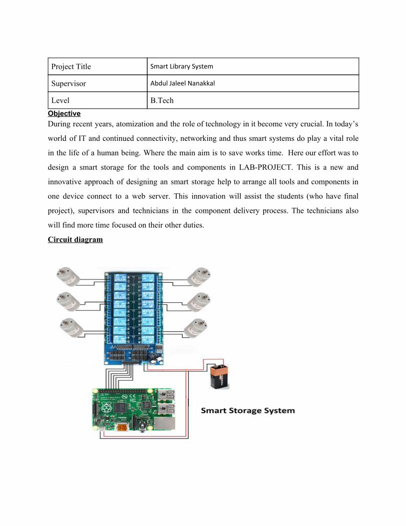
Project Title Smart Library System
Supervisor Abdul Jaleel Nanakkal
Level B.Tech Objective During recent years, atomization and the role of technology in it become very crucial. In today’s
world of IT and continued connectivity, networking and thus smart systems do play a vital role
in the life of a human being. Where the main aim is to save works time. Here our effort was to
design a smart storage for the tools and components in LAB-PROJECT. This is a new and
innovative approach of designing an smart storage help to arrange all tools and components in
one device connect to a web server. This innovation will assist the students (who have final
project), supervisors and technicians in the component delivery process. The technicians also
will find more time focused on their other duties.
Circuit diagram
OLD PROJECT DATA BASE FOR B.TECH(SEM-2/ 2016-17)
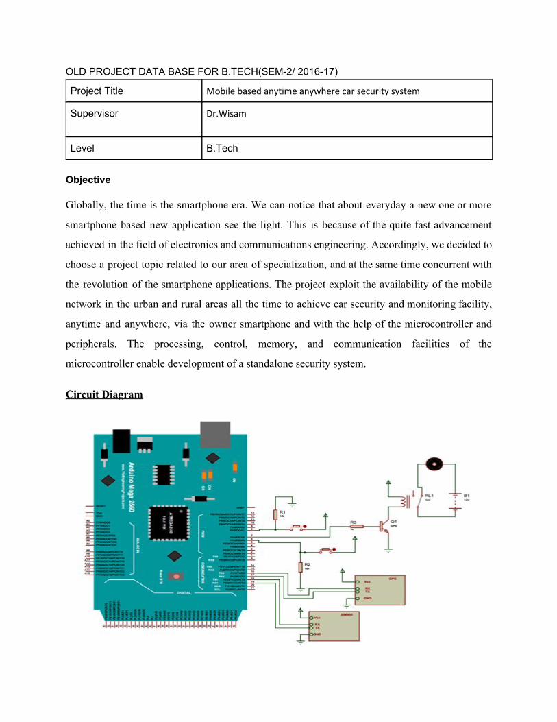
Project Title Mobile based anytime anywhere car security system
Supervisor Dr.Wisam
Level B.Tech
Objective
Globally, the time is the smartphone era. We can notice that about everyday a new one or more
smartphone based new application see the light. This is because of the quite fast advancement
achieved in the field of electronics and communications engineering. Accordingly, we decided to
choose a project topic related to our area of specialization, and at the same time concurrent with
the revolution of the smartphone applications. The project exploit the availability of the mobile
network in the urban and rural areas all the time to achieve car security and monitoring facility,
anytime and anywhere, via the owner smartphone and with the help of the microcontroller and
peripherals. The processing, control, memory, and communication facilities of the
microcontroller enable development of a standalone security system.
Circuit Diagram
Project Title Smart Agriculture system
Supervisor Dr.Bensujin
Level B.Tech
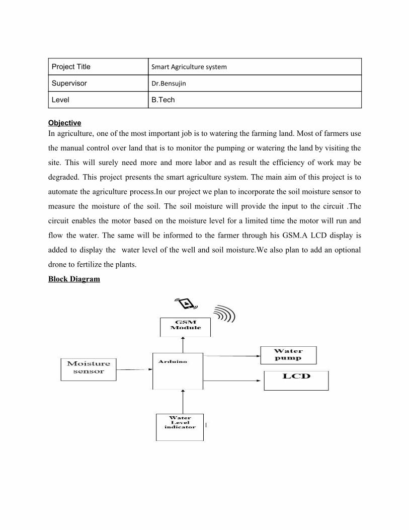
Objective In agriculture, one of the most important job is to watering the farming land. Most of farmers use
the manual control over land that is to monitor the pumping or watering the land by visiting the
site. This will surely need more and more labor and as result the efficiency of work may be
degraded. This project presents the smart agriculture system. The main aim of this project is to
automate the agriculture process.In our project we plan to incorporate the soil moisture sensor to
measure the moisture of the soil. The soil moisture will provide the input to the circuit .The
circuit enables the motor based on the moisture level for a limited time the motor will run and
flow the water. The same will be informed to the farmer through his GSM.A LCD display is
added to display the water level of the well and soil moisture.We also plan to add an optional
drone to fertilize the plants.
Block Diagram
Project Title Intelligent street light system
Supervisor Dr.Rajkumar
Level B.Tech
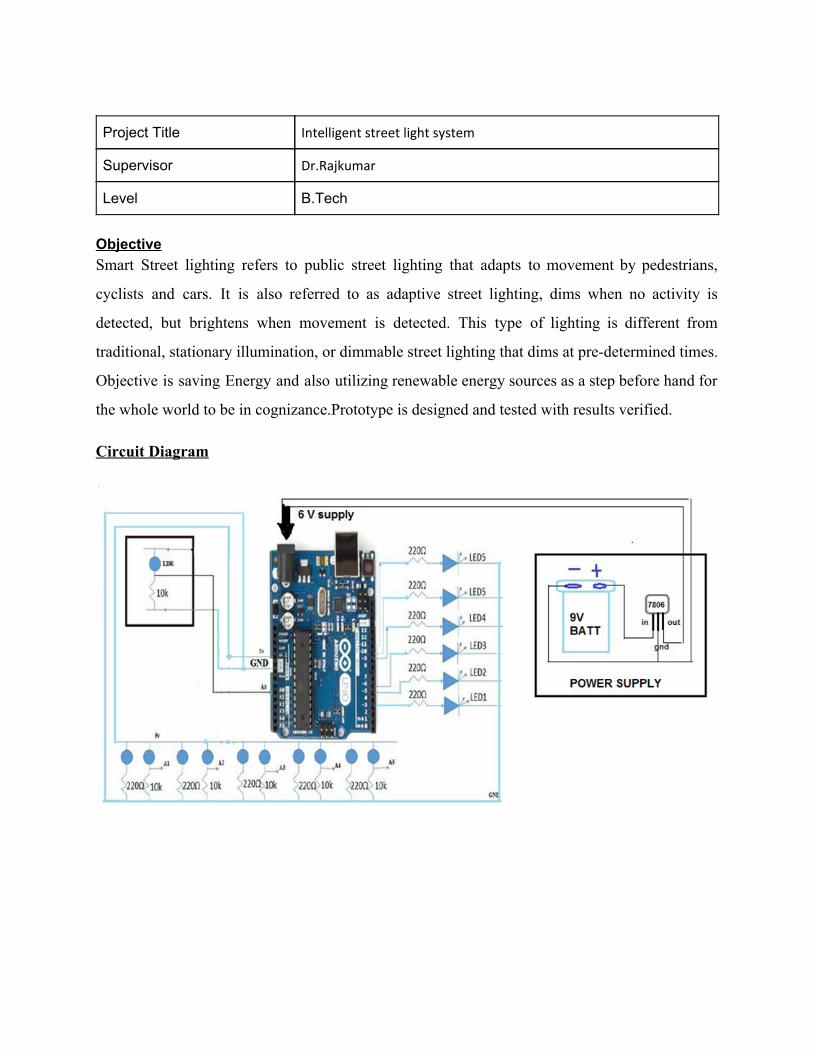
Objective Smart Street lighting refers to public street lighting that adapts to movement by pedestrians,
cyclists and cars. It is also referred to as adaptive street lighting, dims when no activity is
detected, but brightens when movement is detected. This type of lighting is different from
traditional, stationary illumination, or dimmable street lighting that dims at pre-determined times.
Objective is saving Energy and also utilizing renewable energy sources as a step before hand for
the whole world to be in cognizance.Prototype is designed and tested with results verified.
Circuit Diagram
Project Title Android app based smart home controller
Supervisor Dr.Subhra
Level B.Tech
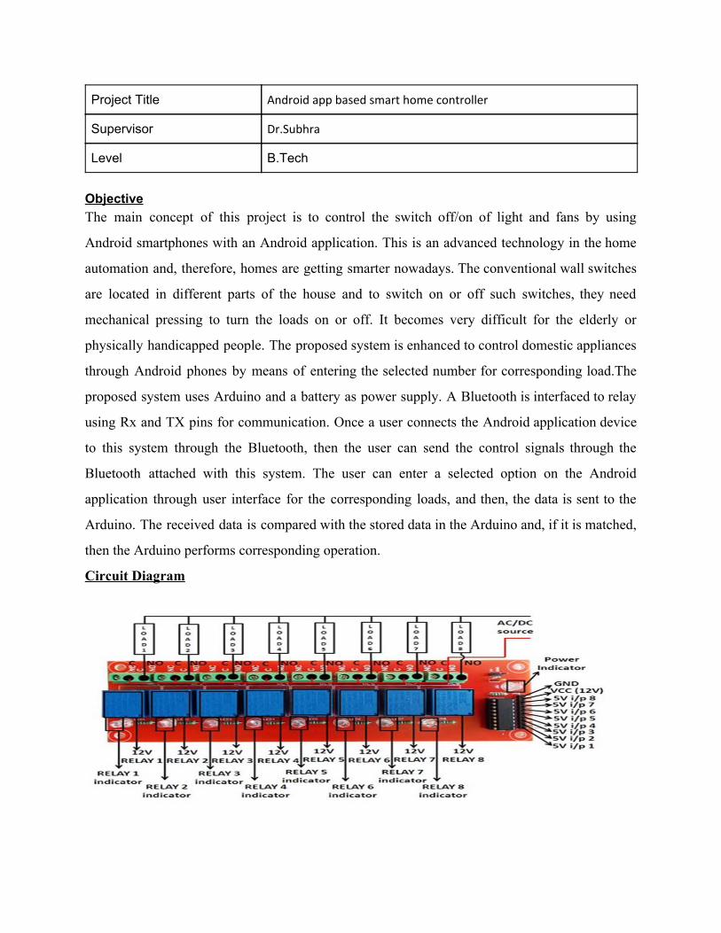
Objective The main concept of this project is to control the switch off/on of light and fans by using
Android smartphones with an Android application. This is an advanced technology in the home
automation and, therefore, homes are getting smarter nowadays. The conventional wall switches
are located in different parts of the house and to switch on or off such switches, they need
mechanical pressing to turn the loads on or off. It becomes very difficult for the elderly or
physically handicapped people. The proposed system is enhanced to control domestic appliances
through Android phones by means of entering the selected number for corresponding load.The
proposed system uses Arduino and a battery as power supply. A Bluetooth is interfaced to relay
using Rx and TX pins for communication. Once a user connects the Android application device
to this system through the Bluetooth, then the user can send the control signals through the
Bluetooth attached with this system. The user can enter a selected option on the Android
application through user interface for the corresponding loads, and then, the data is sent to the
Arduino. The received data is compared with the stored data in the Arduino and, if it is matched,
then the Arduino performs corresponding operation.
Circuit Diagram
Project Title Android based industrial smart processor
Supervisor Dr.Subhra
Level B.Tech
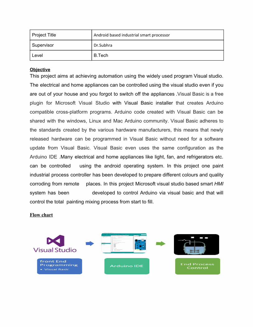
Objective This project aims at achieving automation using the widely used program Visual studio.
The electrical and home appliances can be controlled using the visual studio even if you
are out of your house and you forgot to switch off the appliances .Visual Basic is a free
plugin for Microsoft Visual Studio with Visual Basic installer that creates Arduino
compatible cross-platform programs. Arduino code created with Visual Basic can be
shared with the windows, Linux and Mac Arduino community. Visual Basic adheres to
the standards created by the various hardware manufacturers, this means that newly
released hardware can be programmed in Visual Basic without need for a software
update from Visual Basic. Visual Basic even uses the same configuration as the
Arduino IDE .Many electrical and home appliances like light, fan, and refrigerators etc.
can be controlled using the android operating system. In this project one paint
industrial process controller has been developed to prepare different colours and quality
corroding from remote places. In this project Microsoft visual studio based smart HMI
system has been developed to control Arduino via visual basic and that will
control the total painting mixing process from start to fill.
Flow chart
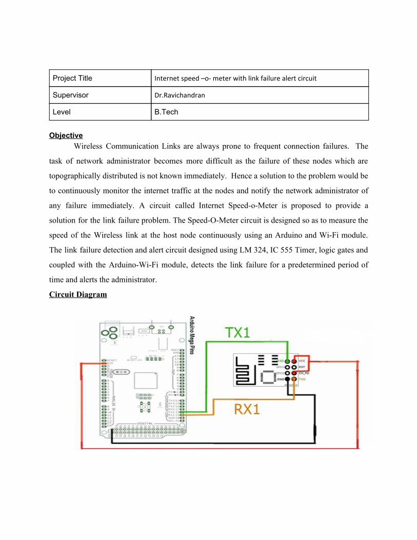
Project Title Internet speed –o- meter with link failure alert circuit
Supervisor Dr.Ravichandran
Level B.Tech
Objective
Wireless Communication Links are always prone to frequent connection failures. The
task of network administrator becomes more difficult as the failure of these nodes which are
topographically distributed is not known immediately. Hence a solution to the problem would be
to continuously monitor the internet traffic at the nodes and notify the network administrator of
any failure immediately. A circuit called Internet Speed-o-Meter is proposed to provide a
solution for the link failure problem. The Speed-O-Meter circuit is designed so as to measure the
speed of the Wireless link at the host node continuously using an Arduino and Wi-Fi module.
The link failure detection and alert circuit designed using LM 324, IC 555 Timer, logic gates and
coupled with the Arduino-Wi-Fi module, detects the link failure for a predetermined period of
time and alerts the administrator.
Circuit Diagram

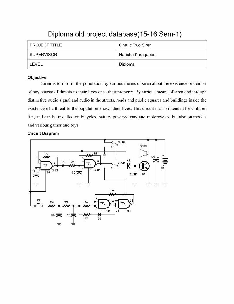
Diploma old project database(15-16 Sem-1) PROJECT TITLE One Ic Two Siren
SUPERVISOR Harisha Karagappa
LEVEL Diploma
Objective
Siren is to inform the population by various means of siren about the existence or demise
of any source of threats to their lives or to their property. By various means of siren and through
distinctive audio signal and audio in the streets, roads and public squares and buildings inside the
existence of a threat to the population knows their lives. This circuit is also intended for children
fun, and can be installed on bicycles, battery powered cars and motorcycles, but also on models
and various games and toys.
Circuit Diagram
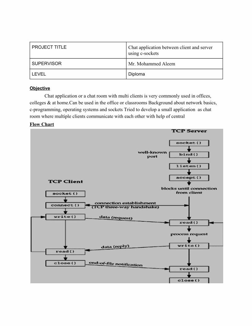
PROJECT TITLE Chat application between client and server using c-sockets
SUPERVISOR Mr. Mohammed Aleem
LEVEL Diploma
Objective
Chat application or a chat room with multi clients is very commonly used in offices, colleges & at home.Can be used in the office or classrooms Background about network basics, c-programming, operating systems and sockets Tried to develop a small application as chat room where multiple clients communicate with each other with help of central Flow Chart
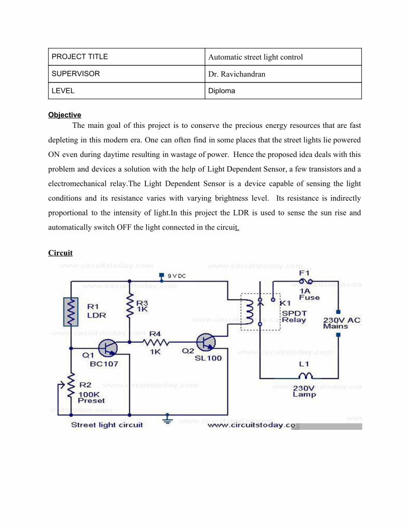
PROJECT TITLE Automatic street light control
SUPERVISOR Dr. Ravichandran
LEVEL Diploma
Objective
The main goal of this project is to conserve the precious energy resources that are fast
depleting in this modern era. One can often find in some places that the street lights lie powered
ON even during daytime resulting in wastage of power. Hence the proposed idea deals with this
problem and devices a solution with the help of Light Dependent Sensor, a few transistors and a
electromechanical relay.The Light Dependent Sensor is a device capable of sensing the light
conditions and its resistance varies with varying brightness level. Its resistance is indirectly
proportional to the intensity of light.In this project the LDR is used to sense the sun rise and
automatically switch OFF the light connected in the circuit.
Circuit
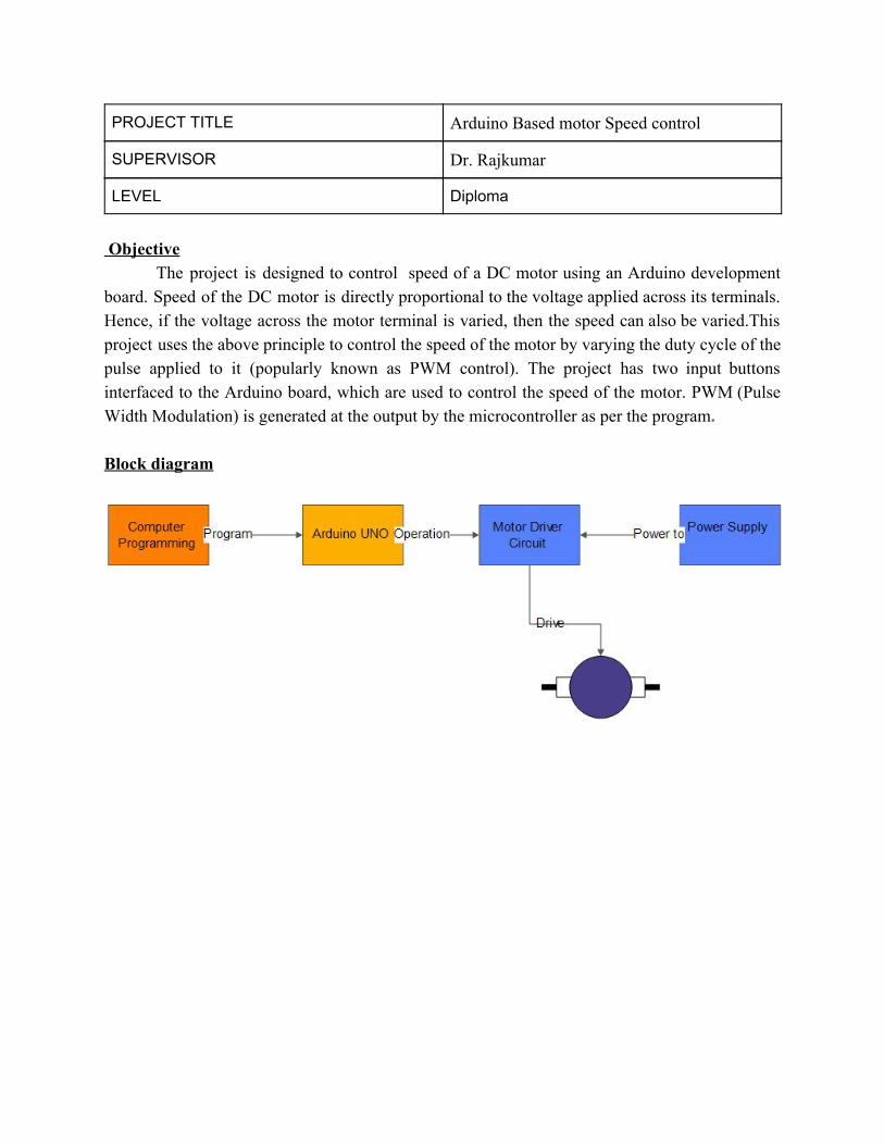
PROJECT TITLE Arduino Based motor Speed control
SUPERVISOR Dr. Rajkumar
LEVEL Diploma
Objective
The project is designed to control speed of a DC motor using an Arduino development board. Speed of the DC motor is directly proportional to the voltage applied across its terminals. Hence, if the voltage across the motor terminal is varied, then the speed can also be varied.This project uses the above principle to control the speed of the motor by varying the duty cycle of the pulse applied to it (popularly known as PWM control). The project has two input buttons interfaced to the Arduino board, which are used to control the speed of the motor. PWM (Pulse Width Modulation) is generated at the output by the microcontroller as per the program. Block diagram
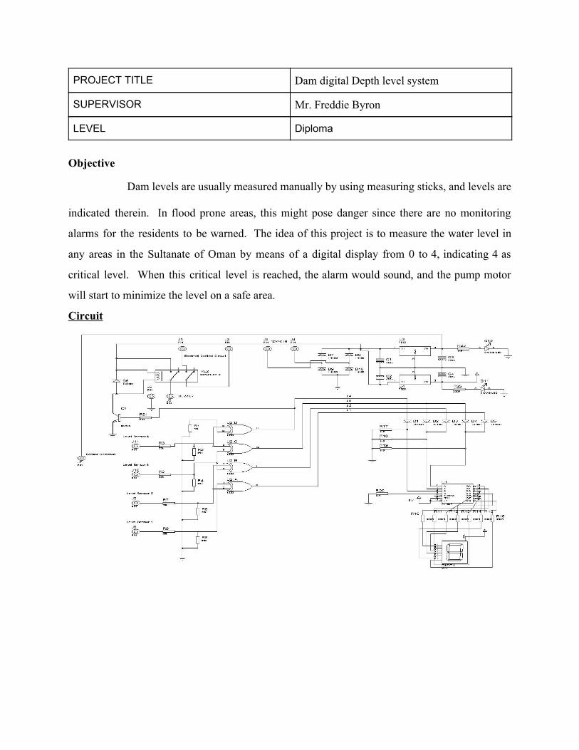
PROJECT TITLE Dam digital Depth level system
SUPERVISOR Mr. Freddie Byron
LEVEL Diploma
Objective
Dam levels are usually measured manually by using measuring sticks, and levels are
indicated therein. In flood prone areas, this might pose danger since there are no monitoring
alarms for the residents to be warned. The idea of this project is to measure the water level in
any areas in the Sultanate of Oman by means of a digital display from 0 to 4, indicating 4 as
critical level. When this critical level is reached, the alarm would sound, and the pump motor
will start to minimize the level on a safe area.
Circuit
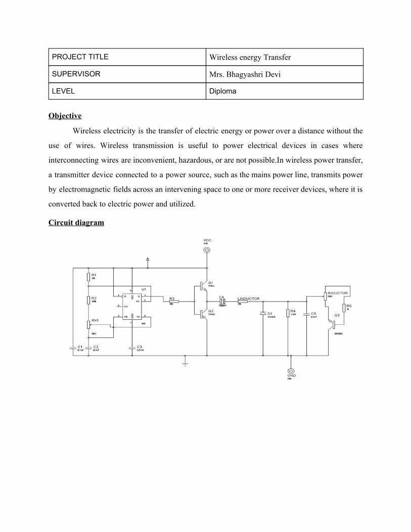
PROJECT TITLE Wireless energy Transfer
SUPERVISOR Mrs. Bhagyashri Devi
LEVEL Diploma
Objective
Wireless electricity is the transfer of electric energy or power over a distance without the
use of wires. Wireless transmission is useful to power electrical devices in cases where
interconnecting wires are inconvenient, hazardous, or are not possible.In wireless power transfer,
a transmitter device connected to a power source, such as the mains power line, transmits power
by electromagnetic fields across an intervening space to one or more receiver devices, where it is
converted back to electric power and utilized.
Circuit diagram
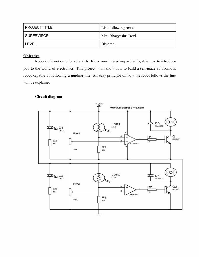
PROJECT TITLE Line following robot
SUPERVISOR Mrs. Bhagyashri Devi
LEVEL Diploma
Objective
Robotics is not only for scientists. It’s a very interesting and enjoyable way to introduce
you to the world of electronics. This project will show how to build a self-made autonomous
robot capable of following a guiding line. An easy principle on how the robot follows the line
will be explained
Circuit diagram
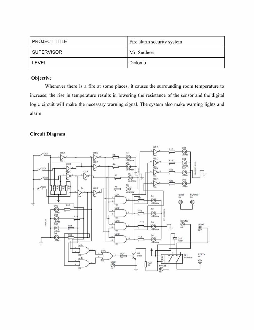
PROJECT TITLE Fire alarm security system
SUPERVISOR Mr. Sudheer
LEVEL Diploma
Objective
Whenever there is a fire at some places, it causes the surrounding room temperature to
increase, the rise in temperature results in lowering the resistance of the sensor and the digital
logic circuit will make the necessary warning signal. The system also make warning lights and
alarm
Circuit Diagram
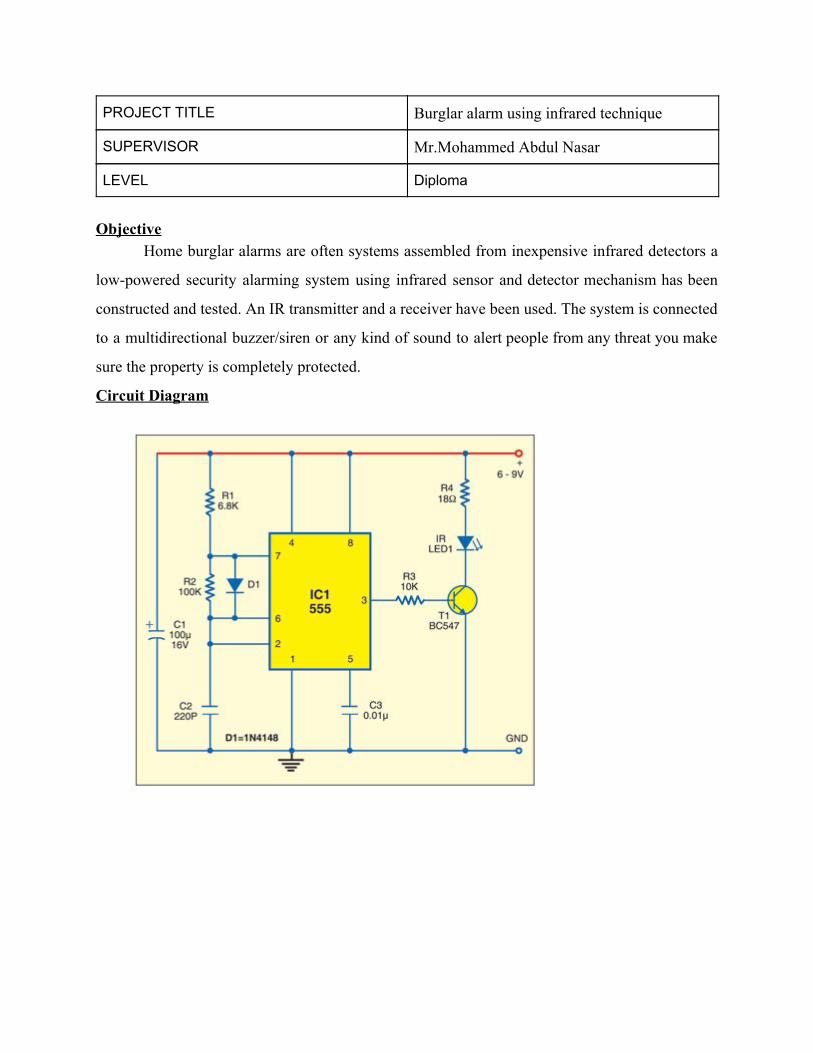
PROJECT TITLE Burglar alarm using infrared technique
SUPERVISOR Mr.Mohammed Abdul Nasar
LEVEL Diploma
Objective
Home burglar alarms are often systems assembled from inexpensive infrared detectors a
low-powered security alarming system using infrared sensor and detector mechanism has been
constructed and tested. An IR transmitter and a receiver have been used. The system is connected
to a multidirectional buzzer/siren or any kind of sound to alert people from any threat you make
sure the property is completely protected.
Circuit Diagram
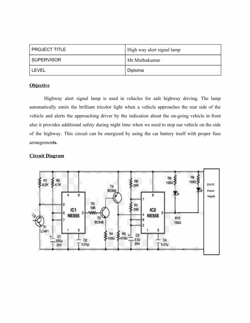
PROJECT TITLE High way alert signal lamp
SUPERVISOR Mr.Muthukumar
LEVEL Diploma
Objective
Highway alert signal lamp is used in vehicles for safe highway driving. The lamp
automatically emits the brilliant tricolor light when a vehicle approaches the rear side of the
vehicle and alerts the approaching driver by the indication about the on-going vehicle in front
also it provides additional safety during night time when we need to stop our vehicle on the side
of the highway. This circuit can be energized by using the car battery itself with proper fuse
arrangements.
Circuit Diagram
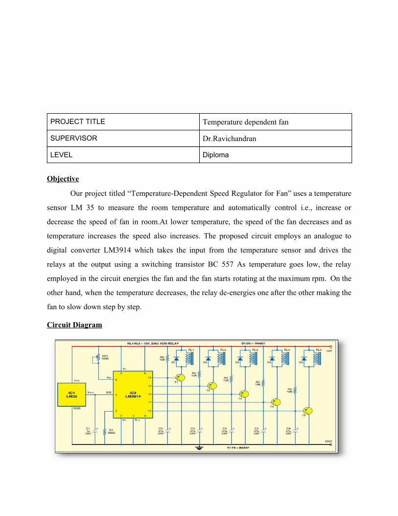
PROJECT TITLE Temperature dependent fan
SUPERVISOR Dr.Ravichandran
LEVEL Diploma
Objective
Our project titled “Temperature-Dependent Speed Regulator for Fan” uses a temperature
sensor LM 35 to measure the room temperature and automatically control i.e., increase or
decrease the speed of fan in room.At lower temperature, the speed of the fan decreases and as
temperature increases the speed also increases. The proposed circuit employs an analogue to
digital converter LM3914 which takes the input from the temperature sensor and drives the
relays at the output using a switching transistor BC 557 As temperature goes low, the relay
employed in the circuit energies the fan and the fan starts rotating at the maximum rpm. On the
other hand, when the temperature decreases, the relay de-energies one after the other making the
fan to slow down step by step.
Circuit Diagram
Diploma old project database(15-16 Sem-2)
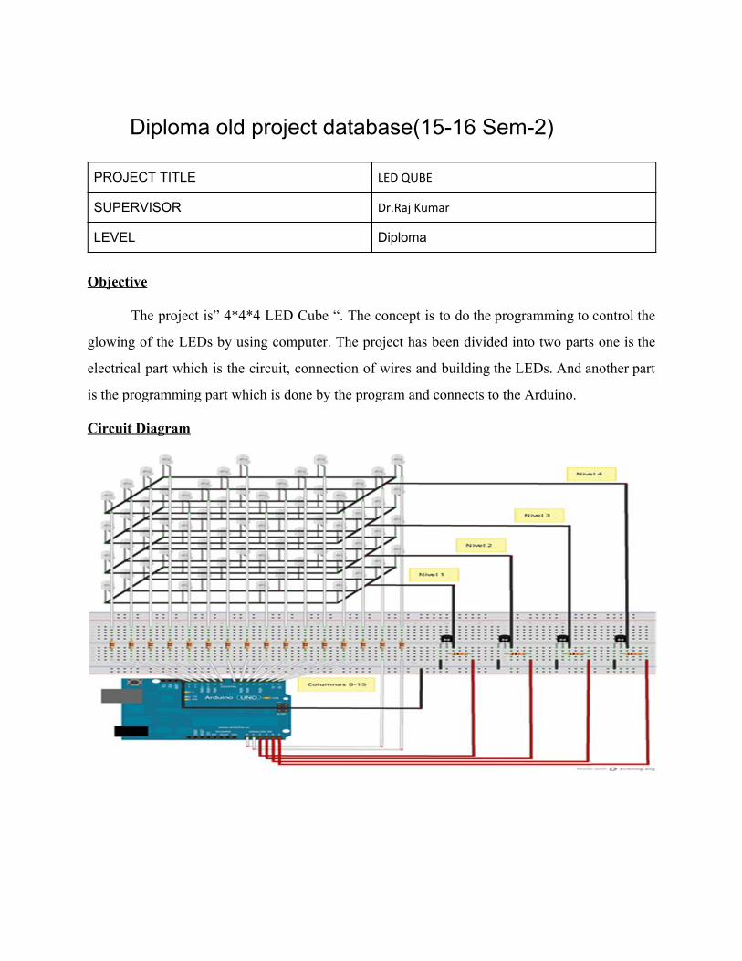
PROJECT TITLE LED QUBE
SUPERVISOR Dr.Raj Kumar
LEVEL Diploma
Objective
The project is” 4*4*4 LED Cube “. The concept is to do the programming to control the
glowing of the LEDs by using computer. The project has been divided into two parts one is the
electrical part which is the circuit, connection of wires and building the LEDs. And another part
is the programming part which is done by the program and connects to the Arduino.
Circuit Diagram
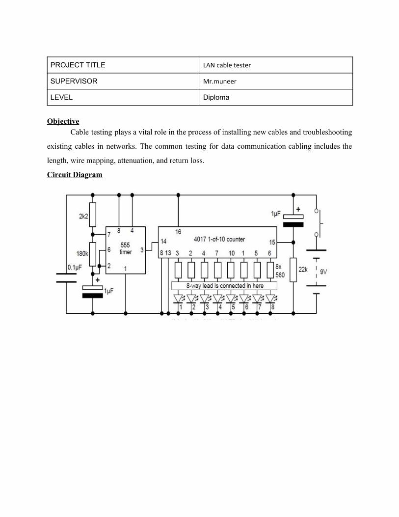
PROJECT TITLE LAN cable tester
SUPERVISOR Mr.muneer
LEVEL Diploma
Objective
Cable testing plays a vital role in the process of installing new cables and troubleshooting
existing cables in networks. The common testing for data communication cabling includes the
length, wire mapping, attenuation, and return loss.
Circuit Diagram
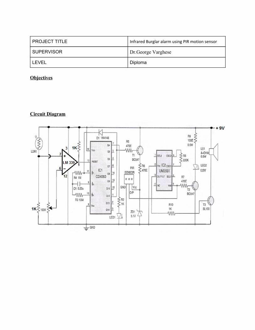
PROJECT TITLE Infrared Burglar alarm using PIR motion sensor
SUPERVISOR Dr.George Varghese
LEVEL Diploma
Objectives
Circuit Diagram
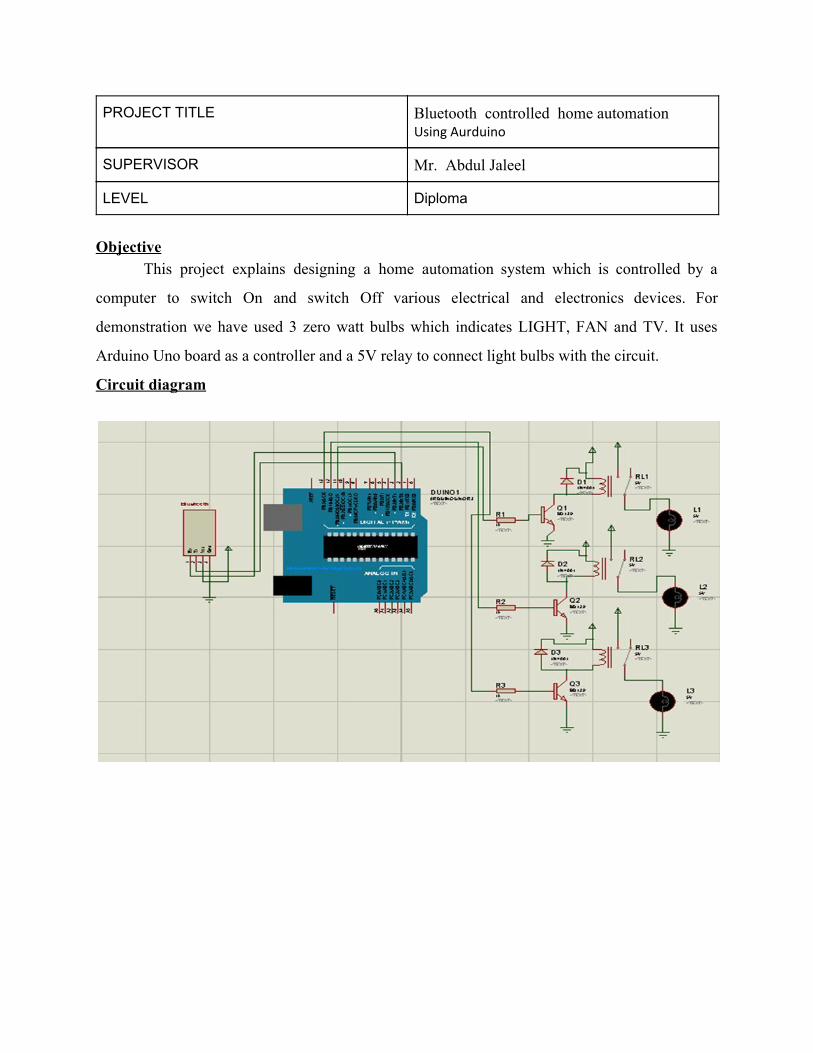
PROJECT TITLE Bluetooth controlled home automation Using Aurduino
SUPERVISOR Mr. Abdul Jaleel
LEVEL Diploma
Objective
This project explains designing a home automation system which is controlled by a
computer to switch On and switch Off various electrical and electronics devices. For
demonstration we have used 3 zero watt bulbs which indicates LIGHT, FAN and TV. It uses
Arduino Uno board as a controller and a 5V relay to connect light bulbs with the circuit.
Circuit diagram
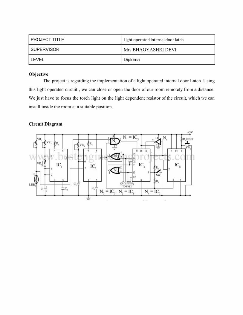
PROJECT TITLE Light operated internal door latch
SUPERVISOR Mrs.BHAGYASHRI DEVI
LEVEL Diploma
Objective
The project is regarding the implementation of a light operated internal door Latch. Using
this light operated circuit , we can close or open the door of our room remotely from a distance.
We just have to focus the torch light on the light dependent resistor of the circuit, which we can
install inside the room at a suitable position.
Circuit Diagram
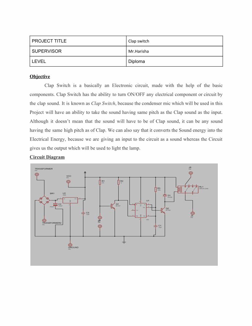
PROJECT TITLE Clap switch
SUPERVISOR Mr.Harisha
LEVEL Diploma
Objective
Clap Switch is a basically an Electronic circuit, made with the help of the basic
components. Clap Switch has the ability to turn ON/OFF any electrical component or circuit by
the clap sound. It is known as Clap Switch, because the condenser mic which will be used in this
Project will have an ability to take the sound having same pitch as the Clap sound as the input.
Although it doesn’t mean that the sound will have to be of Clap sound, it can be any sound
having the same high pitch as of Clap. We can also say that it converts the Sound energy into the
Electrical Energy, because we are giving an input to the circuit as a sound whereas the Circuit
gives us the output which will be used to light the lamp.
Circuit Diagram
Diploma old project database(15-16 Sem-3)
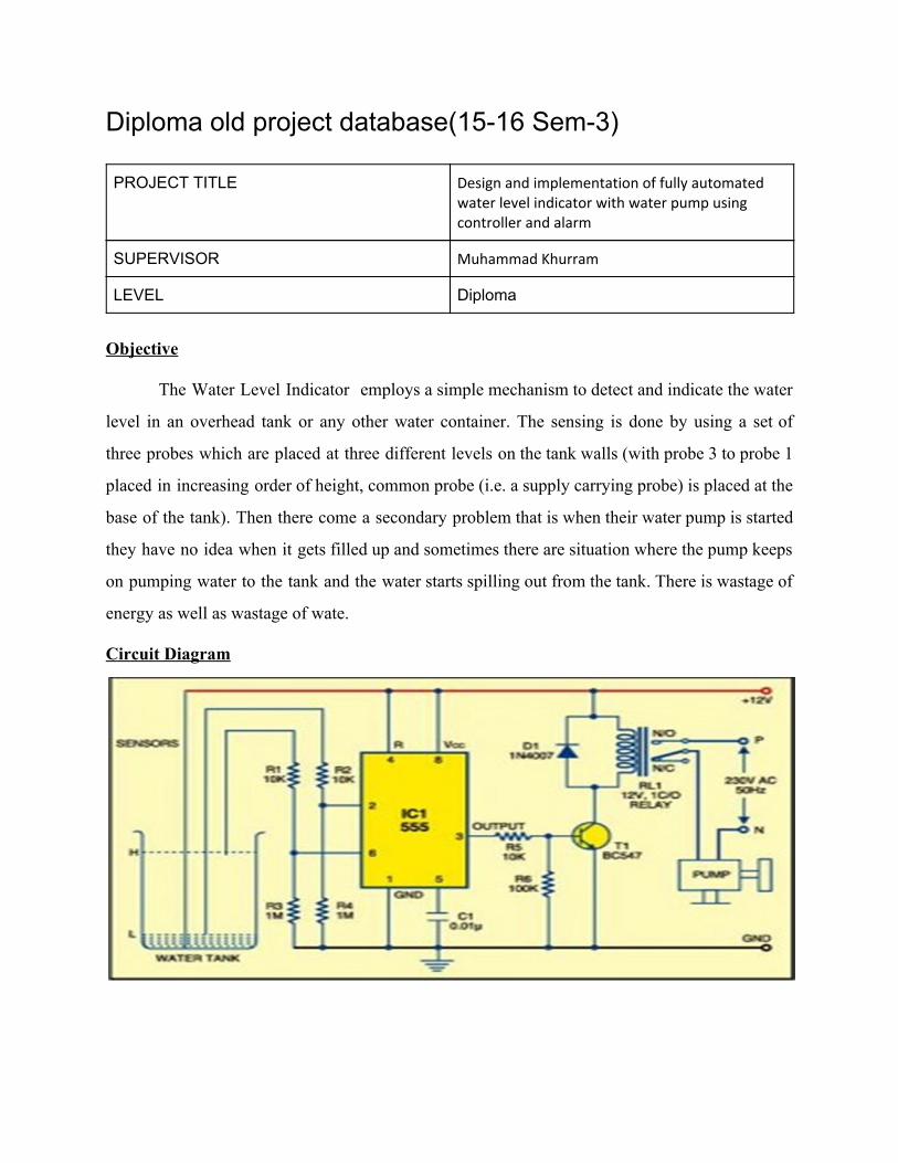
PROJECT TITLE Design and implementation of fully automated water level indicator with water pump using controller and alarm
SUPERVISOR Muhammad Khurram
LEVEL Diploma
Objective
The Water Level Indicator employs a simple mechanism to detect and indicate the water
level in an overhead tank or any other water container. The sensing is done by using a set of
three probes which are placed at three different levels on the tank walls (with probe 3 to probe 1
placed in increasing order of height, common probe (i.e. a supply carrying probe) is placed at the
base of the tank). Then there come a secondary problem that is when their water pump is started
they have no idea when it gets filled up and sometimes there are situation where the pump keeps
on pumping water to the tank and the water starts spilling out from the tank. There is wastage of
energy as well as wastage of wate.
Circuit Diagram
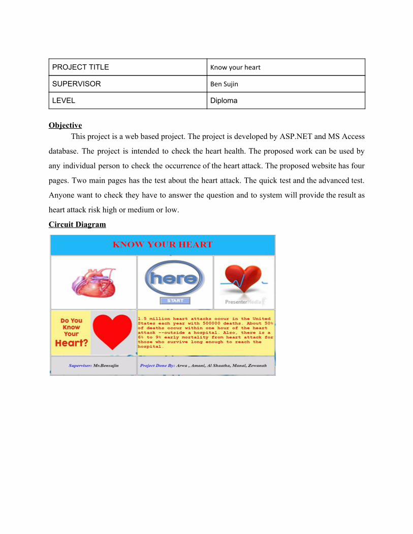
PROJECT TITLE Know your heart
SUPERVISOR Ben Sujin
LEVEL Diploma
Objective
This project is a web based project. The project is developed by ASP.NET and MS Access
database. The project is intended to check the heart health. The proposed work can be used by
any individual person to check the occurrence of the heart attack. The proposed website has four
pages. Two main pages has the test about the heart attack. The quick test and the advanced test.
Anyone want to check they have to answer the question and to system will provide the result as
heart attack risk high or medium or low.
Circuit Diagram
PROJECT TITLE Connecting different devices using DHCP server and fire wall
SUPERVISOR Zafar Iqbal
LEVEL Diploma
Objectives
Our project is connecting different devices using DHCP server and firewall. These days’
People need to be close to some in their communication. So we made a wireless network, make people
communicate easier and takes a less time. Because the world has begun to evolve
Rapidly, Making people in need of modern techniques, useful and serve the global village broadly. We
have chosen a project in which we will connect different wireless network where IPs will be assigned
automatically for each device through a DHCP server. To make the network secure and reliable we
will use a firewall so that we can restrict our network with strangers, and unauthorized access.
Circuit Diagram
PROJECT TITLE Automatic Washroom Lighting system
SUPERVISOR Muthukumarl
LEVEL Diploma
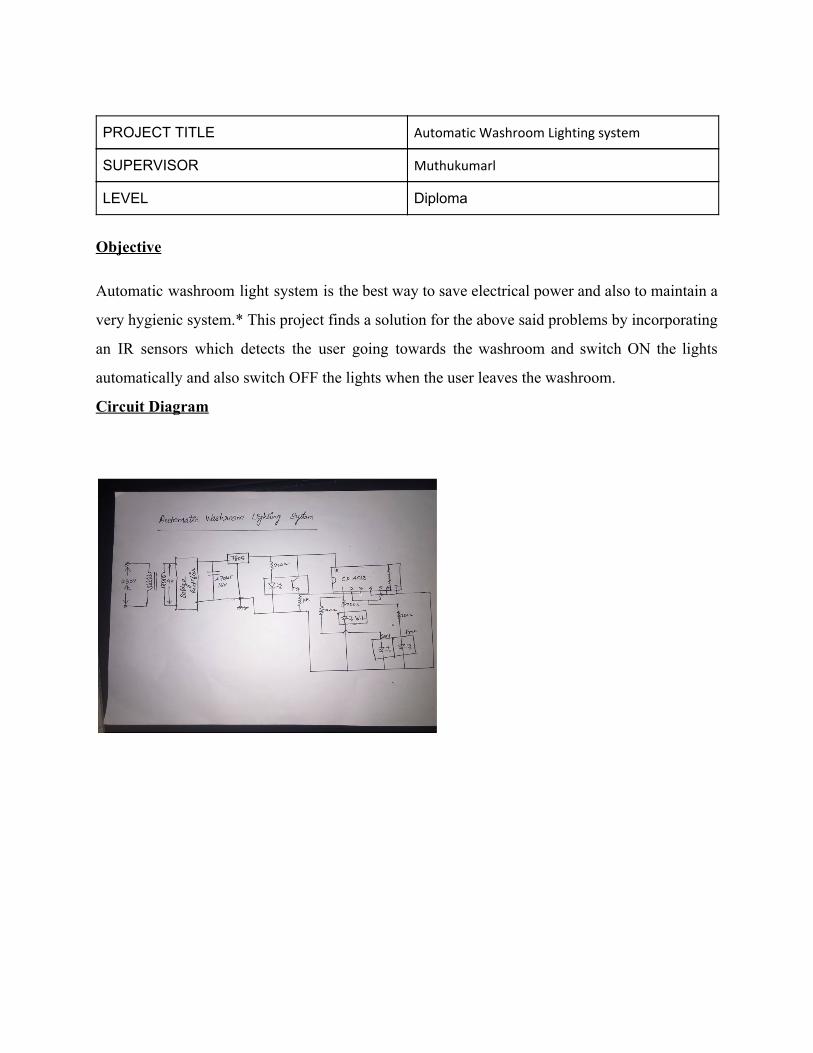
Objective Automatic washroom light system is the best way to save electrical power and also to maintain a
very hygienic system.* This project finds a solution for the above said problems by incorporating
an IR sensors which detects the user going towards the washroom and switch ON the lights
automatically and also switch OFF the lights when the user leaves the washroom.
Circuit Diagram
PROJECT TITLE Mobile Bugtem
SUPERVISOR Harisha Karagappa
LEVEL Diploma
Objectives
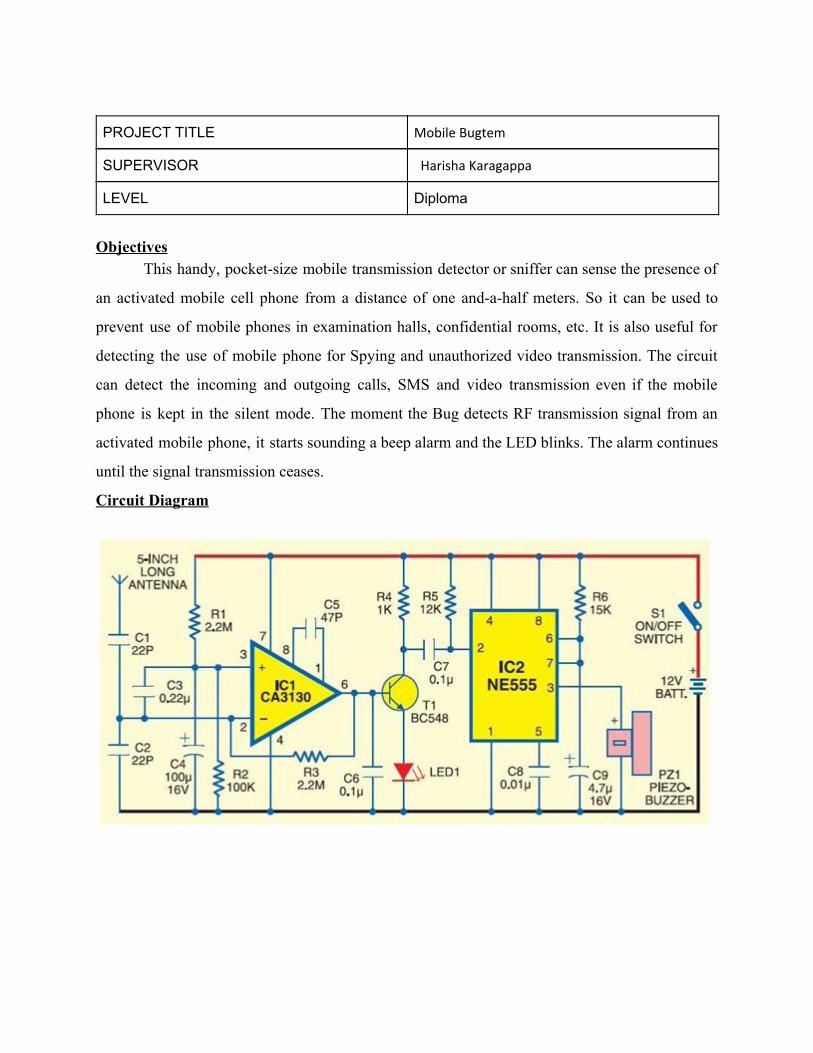
This handy, pocket-size mobile transmission detector or sniffer can sense the presence of
an activated mobile cell phone from a distance of one and-a-half meters. So it can be used to
prevent use of mobile phones in examination halls, confidential rooms, etc. It is also useful for
detecting the use of mobile phone for Spying and unauthorized video transmission. The circuit
can detect the incoming and outgoing calls, SMS and video transmission even if the mobile
phone is kept in the silent mode. The moment the Bug detects RF transmission signal from an
activated mobile phone, it starts sounding a beep alarm and the LED blinks. The alarm continues
until the signal transmission ceases.
Circuit Diagram
PROJECT TITLE Remote controlled Fan speed Controller
SUPERVISOR Freddie Byron N Lumang
LEVEL Diploma
Objectives
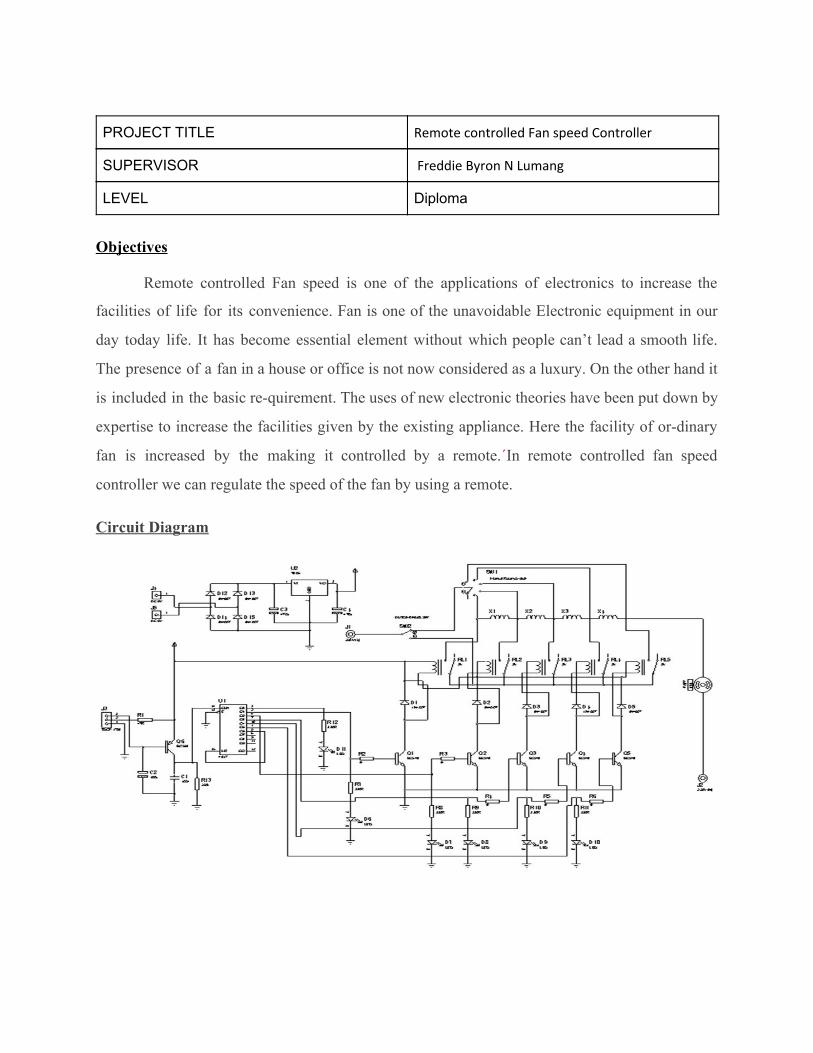
Remote controlled Fan speed is one of the applications of electronics to increase the
facilities of life for its convenience. Fan is one of the unavoidable Electronic equipment in our
day today life. It has become essential element without which people can’t lead a smooth life.
The presence of a fan in a house or office is not now considered as a luxury. On the other hand it
is included in the basic re-quirement. The uses of new electronic theories have been put down by
expertise to increase the facilities given by the existing appliance. Here the facility of or-dinary
fan is increased by the making it controlled by a remote.´In remote controlled fan speed
controller we can regulate the speed of the fan by using a remote.
Circuit Diagram
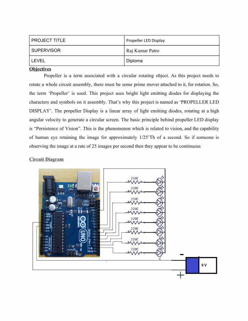
PROJECT TITLE Propeller LED Display
SUPERVISOR Raj Kumar Patro
LEVEL Diploma
Objectives Propeller is a term associated with a circular rotating object. As this project needs to
rotate a whole circuit assembly, there must be some prime mover attached to it, for rotation. So,
the term ‘Propeller’ is used. This project uses bright light emitting diodes for displaying the
characters and symbols on it assembly. That’s why this project is named as ‘PROPELLER LED
DISPLAY’. The propeller Display is a linear array of light emitting diodes, rotating at a high
angular velocity to generate a circular screen. The basic principle behind propeller LED display
is “Persistence of Vision”. This is the phenomenon which is related to vision, and the capability
of human eye retaining the image for approximately 1/25’Th of a second. So if someone is
observing the image at a rate of 25 images per second then they appear to be continuous
Circuit Diagram
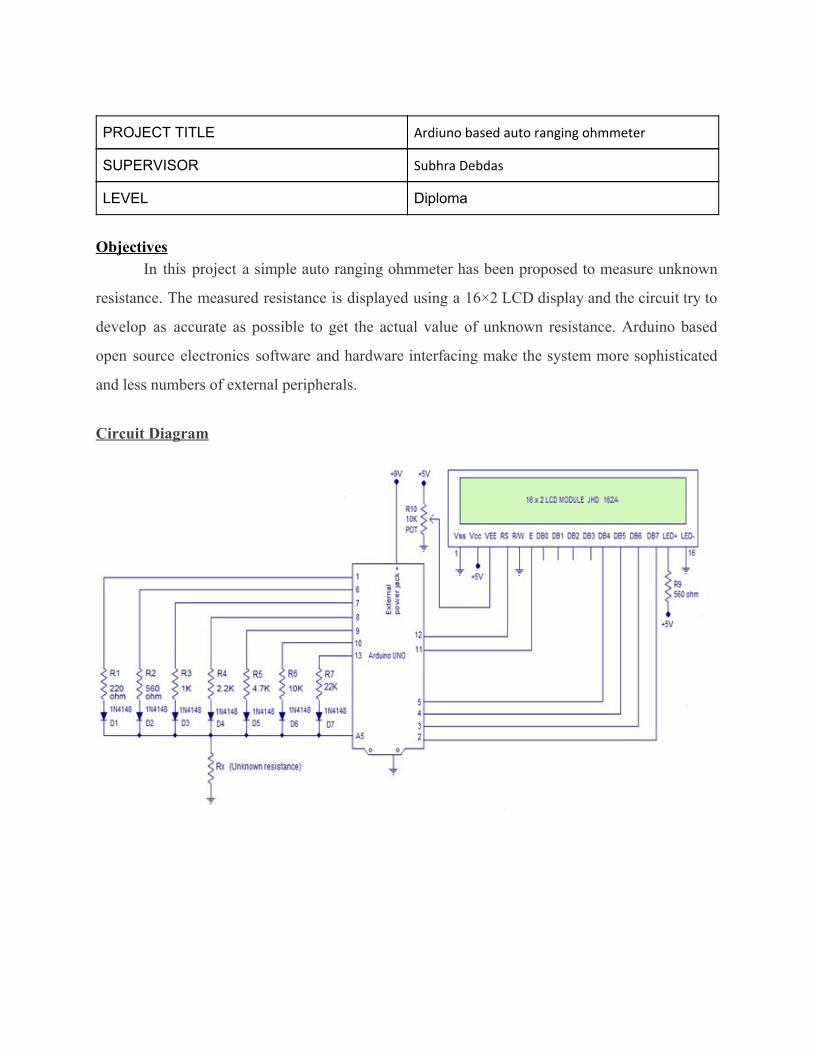
PROJECT TITLE Ardiuno based auto ranging ohmmeter
SUPERVISOR Subhra Debdas
LEVEL Diploma
Objectives
In this project a simple auto ranging ohmmeter has been proposed to measure unknown
resistance. The measured resistance is displayed using a 16×2 LCD display and the circuit try to
develop as accurate as possible to get the actual value of unknown resistance. Arduino based
open source electronics software and hardware interfacing make the system more sophisticated
and less numbers of external peripherals.
Circuit Diagram
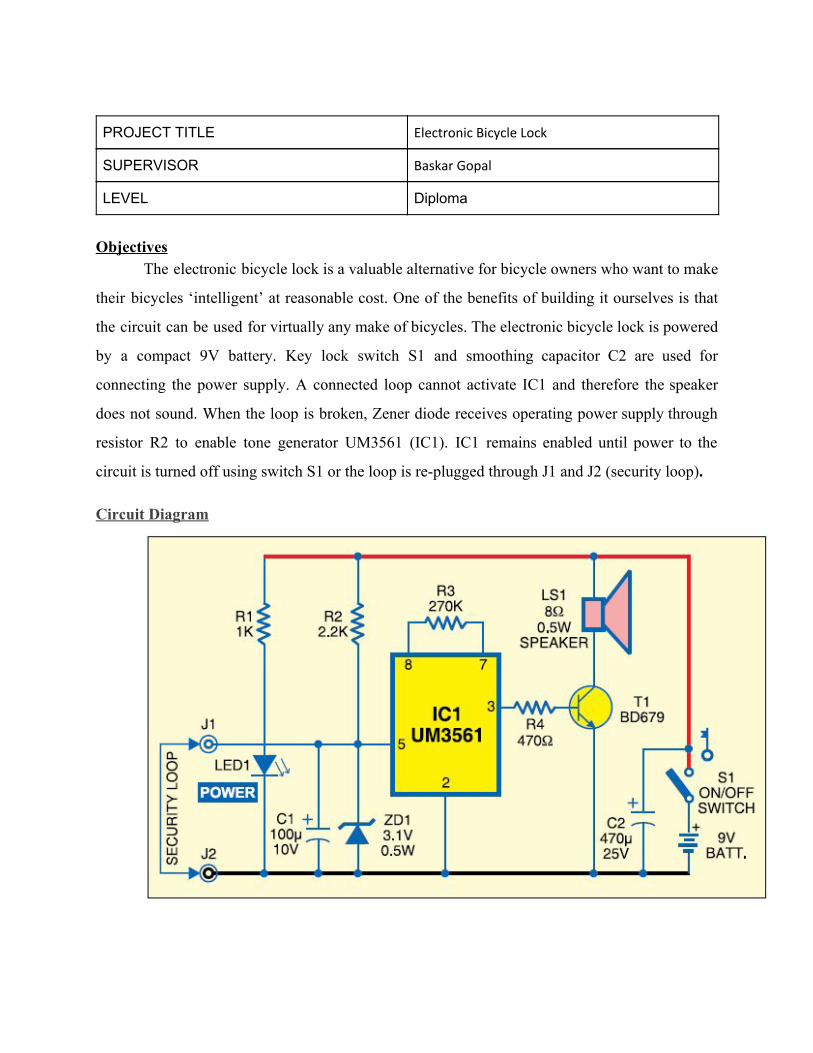
PROJECT TITLE Electronic Bicycle Lock
SUPERVISOR Baskar Gopal
LEVEL Diploma
Objectives
The electronic bicycle lock is a valuable alternative for bicycle owners who want to make
their bicycles ‘intelligent’ at reasonable cost. One of the benefits of building it ourselves is that
the circuit can be used for virtually any make of bicycles. The electronic bicycle lock is powered
by a compact 9V battery. Key lock switch S1 and smoothing capacitor C2 are used for
connecting the power supply. A connected loop cannot activate IC1 and therefore the speaker
does not sound. When the loop is broken, Zener diode receives operating power supply through
resistor R2 to enable tone generator UM3561 (IC1). IC1 remains enabled until power to the
circuit is turned off using switch S1 or the loop is re-plugged through J1 and J2 (security loop).
Circuit Diagram
Diploma old project database(16-17 Sem-1)
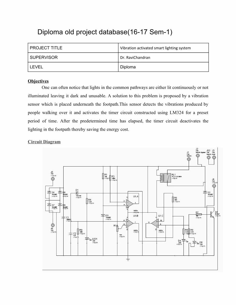
PROJECT TITLE Vibration activated smart lighting system
SUPERVISOR Dr. RaviChandran
LEVEL Diploma
Objectives
One can often notice that lights in the common pathways are either lit continuously or not
illuminated leaving it dark and unusable. A solution to this problem is proposed by a vibration
sensor which is placed underneath the footpath.This sensor detects the vibrations produced by
people walking over it and activates the timer circuit constructed using LM324 for a preset
period of time. After the predetermined time has elapsed, the timer circuit deactivates the
lighting in the footpath thereby saving the energy cost.
Circuit Diagram
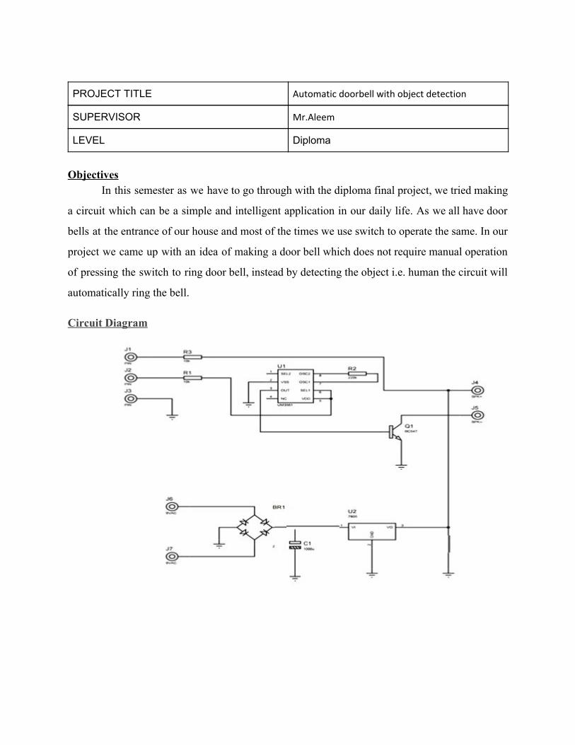
PROJECT TITLE Automatic doorbell with object detection
SUPERVISOR Mr.Aleem
LEVEL Diploma
Objectives
In this semester as we have to go through with the diploma final project, we tried making
a circuit which can be a simple and intelligent application in our daily life. As we all have door
bells at the entrance of our house and most of the times we use switch to operate the same. In our
project we came up with an idea of making a door bell which does not require manual operation
of pressing the switch to ring door bell, instead by detecting the object i.e. human the circuit will
automatically ring the bell.
Circuit Diagram
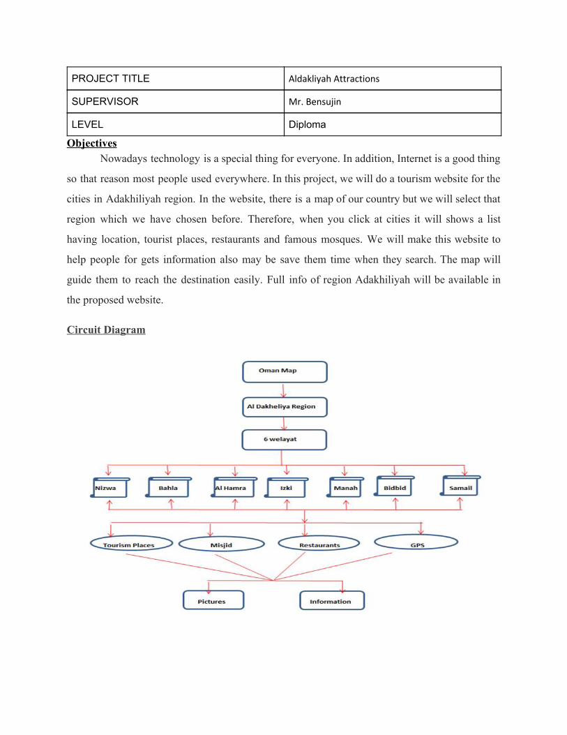
PROJECT TITLE Aldakliyah Attractions
SUPERVISOR Mr. Bensujin
LEVEL Diploma
Objectives Nowadays technology is a special thing for everyone. In addition, Internet is a good thing
so that reason most people used everywhere. In this project, we will do a tourism website for the
cities in Adakhiliyah region. In the website, there is a map of our country but we will select that
region which we have chosen before. Therefore, when you click at cities it will shows a list
having location, tourist places, restaurants and famous mosques. We will make this website to
help people for gets information also may be save them time when they search. The map will
guide them to reach the destination easily. Full info of region Adakhiliyah will be available in
the proposed website.
Circuit Diagram
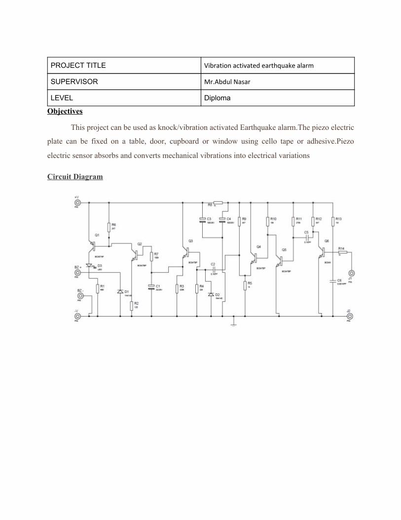
PROJECT TITLE Vibration activated earthquake alarm
SUPERVISOR Mr.Abdul Nasar
LEVEL Diploma
Objectives
This project can be used as knock/vibration activated Earthquake alarm.The piezo electric
plate can be fixed on a table, door, cupboard or window using cello tape or adhesive.Piezo
electric sensor absorbs and converts mechanical vibrations into electrical variations
Circuit Diagram
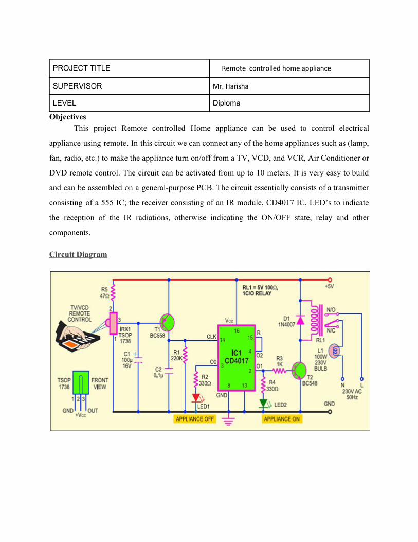
PROJECT TITLE Remo Remote controlled home appliance
SUPERVISOR Mr. Harisha
LEVEL Diploma
Objectives This project Remote controlled Home appliance can be used to control electrical
appliance using remote. In this circuit we can connect any of the home appliances such as (lamp,
fan, radio, etc.) to make the appliance turn on/off from a TV, VCD, and VCR, Air Conditioner or
DVD remote control. The circuit can be activated from up to 10 meters. It is very easy to build
and can be assembled on a general-purpose PCB. The circuit essentially consists of a transmitter
consisting of a 555 IC; the receiver consisting of an IR module, CD4017 IC, LED’s to indicate
the reception of the IR radiations, otherwise indicating the ON/OFF state, relay and other
components.
Circuit Diagram
PROJECT TITLE Remo Automatic street light control system using LDR
and BC 548
SUPERVISOR Mr.Khurram
LEVEL Diploma
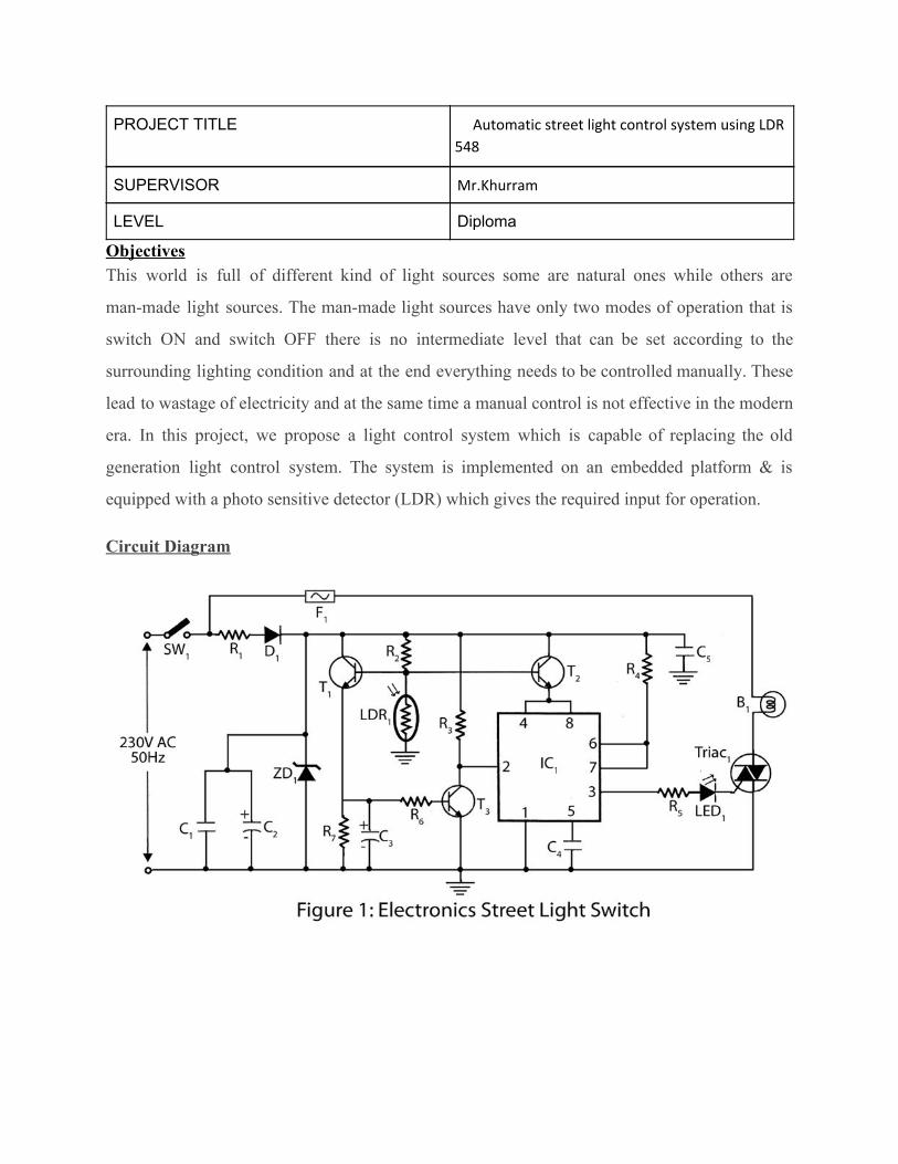
Objectives This world is full of different kind of light sources some are natural ones while others are
man-made light sources. The man-made light sources have only two modes of operation that is
switch ON and switch OFF there is no intermediate level that can be set according to the
surrounding lighting condition and at the end everything needs to be controlled manually. These
lead to wastage of electricity and at the same time a manual control is not effective in the modern
era. In this project, we propose a light control system which is capable of replacing the old
generation light control system. The system is implemented on an embedded platform & is
equipped with a photo sensitive detector (LDR) which gives the required input for operation.
Circuit Diagram
PROJECT TITLE Remo Hybrid solar charger
SUPERVISOR Mr.Gobinathan
LEVEL Diploma
Objectives
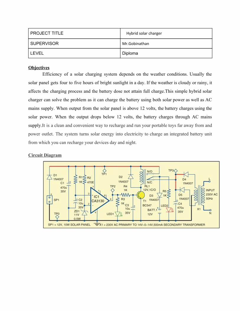
Efficiency of a solar charging system depends on the weather conditions. Usually the
solar panel gets four to five hours of bright sunlight in a day. If the weather is cloudy or rainy, it
affects the charging process and the battery dose not attain full charge.This simple hybrid solar
charger can solve the problem as it can charge the battery using both solar power as well as AC
mains supply. When output from the solar panel is above 12 volts, the battery charges using the
solar power. When the output drops below 12 volts, the battery charges through AC mains
supply.It is a clean and convenient way to recharge and run your portable toys far away from and
power outlet. The system turns solar energy into electricity to charge an integrated battery unit
from which you can recharge your devices day and night.
Circuit Diagram
PROJECT TITLE Remo A temperature sensing based fire alert system
SUPERVISOR Mr.Sameeullah
LEVEL Diploma
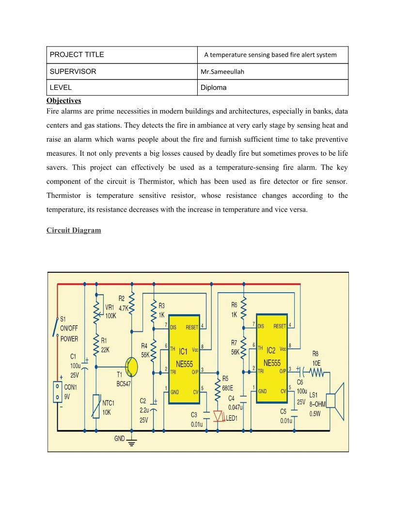
Objectives Fire alarms are prime necessities in modern buildings and architectures, especially in banks, data
centers and gas stations. They detects the fire in ambiance at very early stage by sensing heat and
raise an alarm which warns people about the fire and furnish sufficient time to take preventive
measures. It not only prevents a big losses caused by deadly fire but sometimes proves to be life
savers. This project can effectively be used as a temperature-sensing fire alarm. The key
component of the circuit is Thermistor, which has been used as fire detector or fire sensor.
Thermistor is temperature sensitive resistor, whose resistance changes according to the
temperature, its resistance decreases with the increase in temperature and vice versa.
Circuit Diagram
PROJECT TITLE Remo Fault protection in dc low voltage system
SUPERVISOR Mr.Farooq
LEVEL Diploma
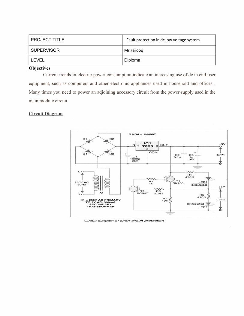
Objectives Current trends in electric power consumption indicate an increasing use of dc in end-user
equipment, such as computers and other electronic appliances used in household and offices .
Many times you need to power an adjoining accessory circuit from the power supply used in the
main module circuit
Circuit Diagram
Diploma old project database(16-17 Sem-2)
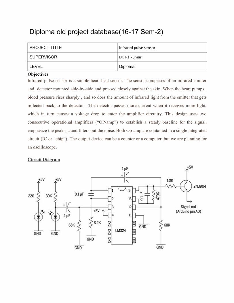
PROJECT TITLE Infrared pulse sensor
SUPERVISOR Dr. Rajkumar
LEVEL Diploma
Objectives Infrared pulse sensor is a simple heart beat sensor. The sensor comprises of an infrared emitter
and detector mounted side-by-side and pressed closely against the skin .When the heart pumps ,
blood pressure rises sharply , and so does the amount of infrared light from the emitter that gets
reflected back to the detector . The detector passes more current when it receives more light,
which in turn causes a voltage drop to enter the amplifier circuitry. This design uses two
consecutive operational amplifiers (“OP-amp”) to establish a steady baseline for the signal,
emphasize the peaks, a and filters out the noise. Both Op-amp are contained in a single integrated
circuit (IC or “chip”). The output device can be a counter or a computer, but we are planning for
an oscilloscope.
Circuit Diagram
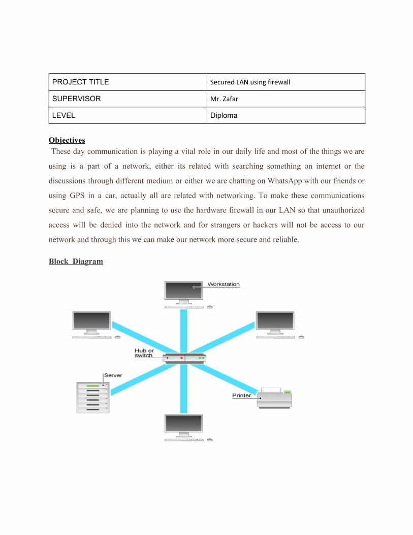
PROJECT TITLE Secured LAN using firewall
SUPERVISOR Mr. Zafar
LEVEL Diploma
Objectives These day communication is playing a vital role in our daily life and most of the things we are
using is a part of a network, either its related with searching something on internet or the
discussions through different medium or either we are chatting on WhatsApp with our friends or
using GPS in a car, actually all are related with networking. To make these communications
secure and safe, we are planning to use the hardware firewall in our LAN so that unauthorized
access will be denied into the network and for strangers or hackers will not be access to our
network and through this we can make our network more secure and reliable.
Block Diagram
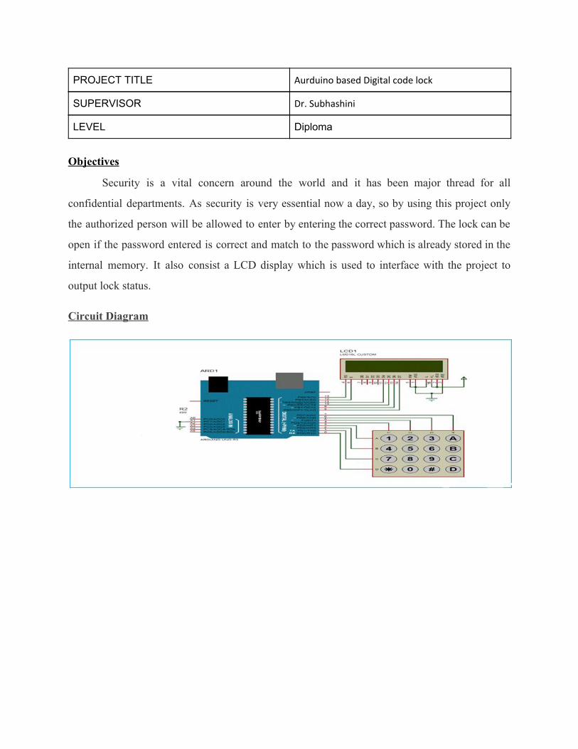
PROJECT TITLE Aurduino based Digital code lock
SUPERVISOR Dr. Subhashini
LEVEL Diploma
Objectives
Security is a vital concern around the world and it has been major thread for all
confidential departments. As security is very essential now a day, so by using this project only
the authorized person will be allowed to enter by entering the correct password. The lock can be
open if the password entered is correct and match to the password which is already stored in the
internal memory. It also consist a LCD display which is used to interface with the project to
output lock status.
Circuit Diagram
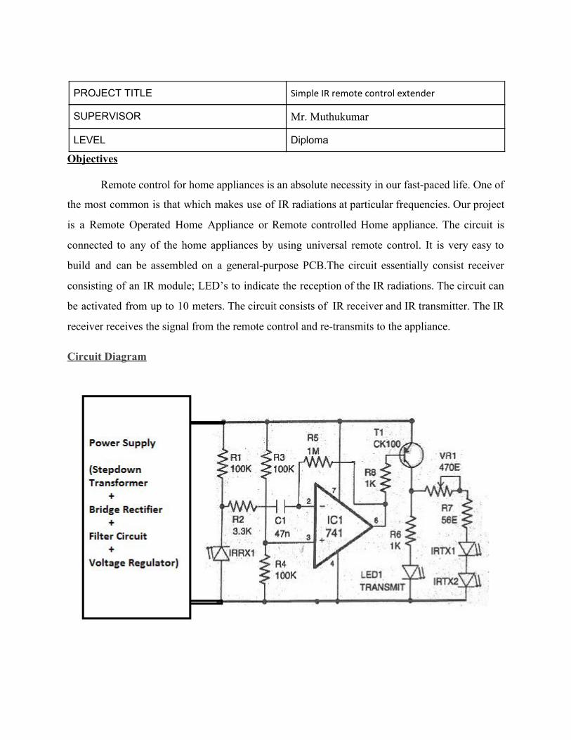
PROJECT TITLE Simple IR remote control extender
SUPERVISOR Mr. Muthukumar
LEVEL Diploma
Objectives
Remote control for home appliances is an absolute necessity in our fast-paced life. One of
the most common is that which makes use of IR radiations at particular frequencies. Our project
is a Remote Operated Home Appliance or Remote controlled Home appliance. The circuit is
connected to any of the home appliances by using universal remote control. It is very easy to
build and can be assembled on a general-purpose PCB.The circuit essentially consist receiver
consisting of an IR module; LED’s to indicate the reception of the IR radiations. The circuit can
be activated from up to 10 meters. The circuit consists of IR receiver and IR transmitter. The IR
receiver receives the signal from the remote control and re-transmits to the appliance.
Circuit Diagram
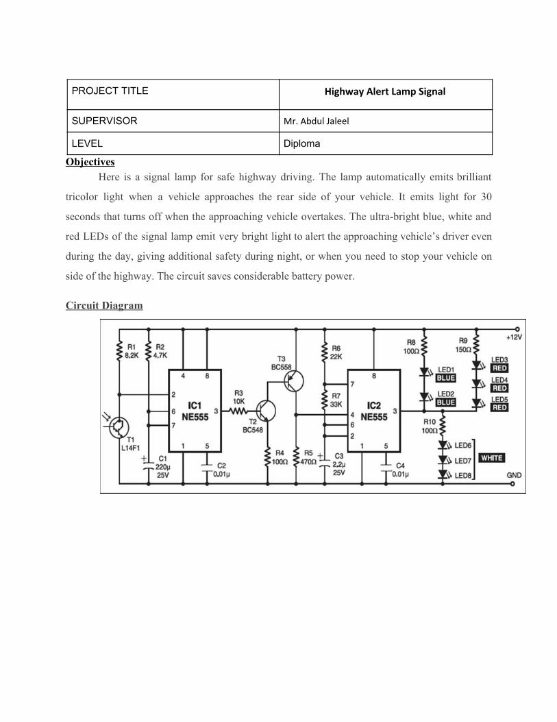
PROJECT TITLE Highway Alert Lamp Signal
SUPERVISOR Mr. Abdul Jaleel
LEVEL Diploma
Objectives Here is a signal lamp for safe highway driving. The lamp automatically emits brilliant
tricolor light when a vehicle approaches the rear side of your vehicle. It emits light for 30
seconds that turns off when the approaching vehicle overtakes. The ultra-bright blue, white and
red LEDs of the signal lamp emit very bright light to alert the approaching vehicle’s driver even
during the day, giving additional safety during night, or when you need to stop your vehicle on
side of the highway. The circuit saves considerable battery power.
Circuit Diagram
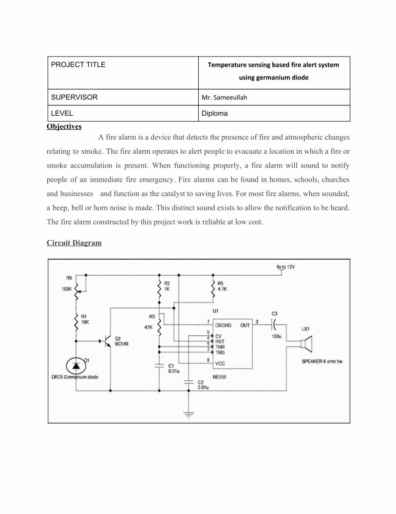
PROJECT TITLE Temperature sensing based fire alert system
using germanium diode
SUPERVISOR Mr. Sameeullah
LEVEL Diploma
Objectives A fire alarm is a device that detects the presence of fire and atmospheric changes
relating to smoke. The fire alarm operates to alert people to evacuate a location in which a fire or
smoke accumulation is present. When functioning properly, a fire alarm will sound to notify
people of an immediate fire emergency. Fire alarms can be found in homes, schools, churches
and businesses and function as the catalyst to saving lives. For most fire alarms, when sounded,
a beep, bell or horn noise is made. This distinct sound exists to allow the notification to be heard.
The fire alarm constructed by this project work is reliable at low cost.
Circuit Diagram
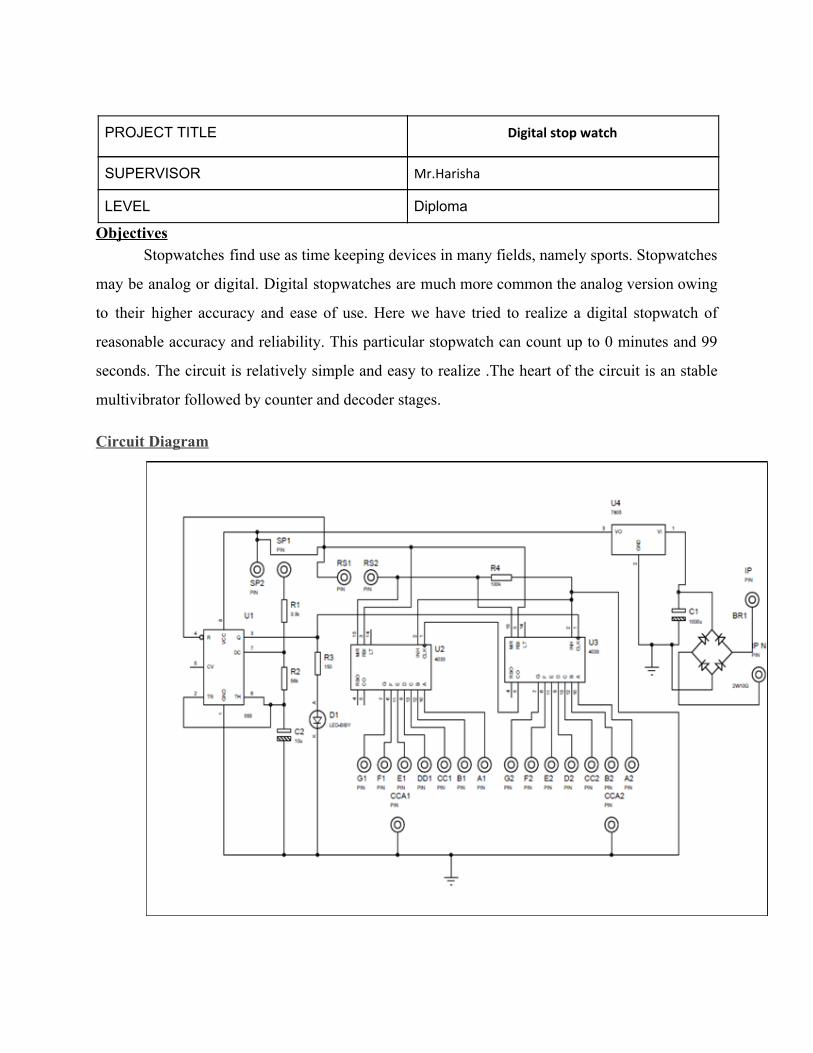
PROJECT TITLE Digital stop watch
SUPERVISOR Mr.Harisha
LEVEL Diploma
Objectives Stopwatches find use as time keeping devices in many fields, namely sports. Stopwatches
may be analog or digital. Digital stopwatches are much more common the analog version owing
to their higher accuracy and ease of use. Here we have tried to realize a digital stopwatch of
reasonable accuracy and reliability. This particular stopwatch can count up to 0 minutes and 99
seconds. The circuit is relatively simple and easy to realize .The heart of the circuit is an stable
multivibrator followed by counter and decoder stages.
Circuit Diagram
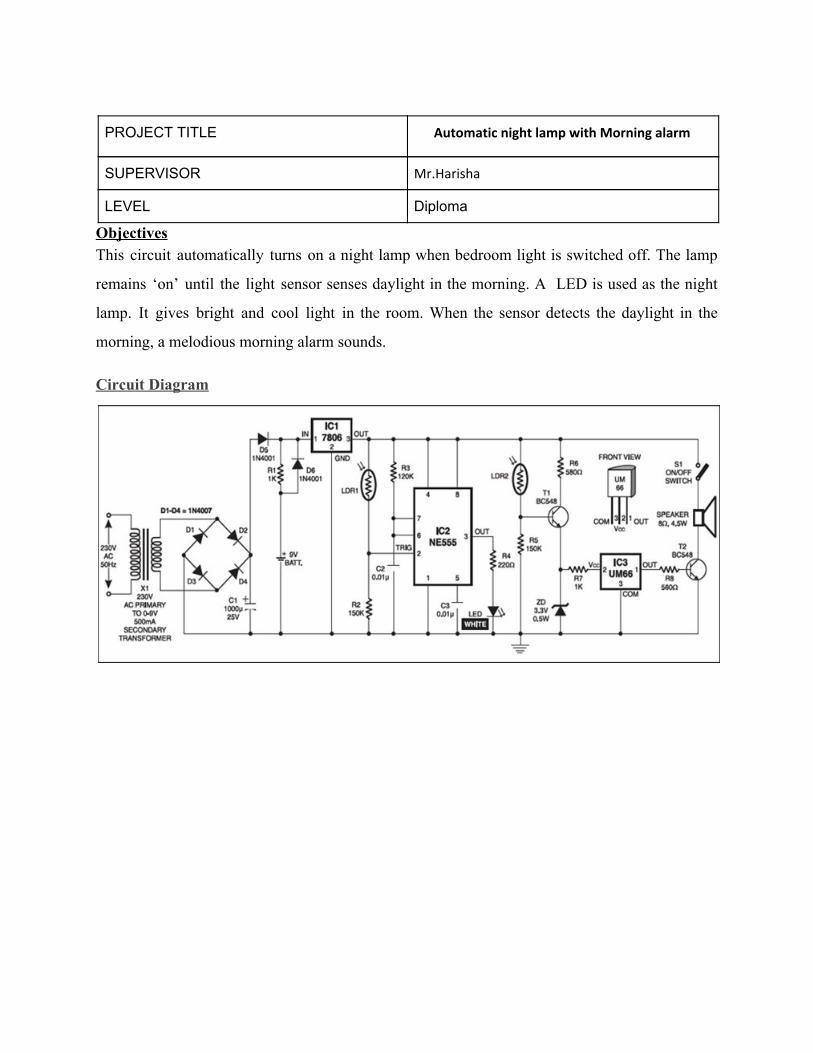
PROJECT TITLE Automatic night lamp with Morning alarm
SUPERVISOR Mr.Harisha
LEVEL Diploma
Objectives This circuit automatically turns on a night lamp when bedroom light is switched off. The lamp
remains ‘on’ until the light sensor senses daylight in the morning. A LED is used as the night
lamp. It gives bright and cool light in the room. When the sensor detects the daylight in the
morning, a melodious morning alarm sounds.
Circuit Diagram
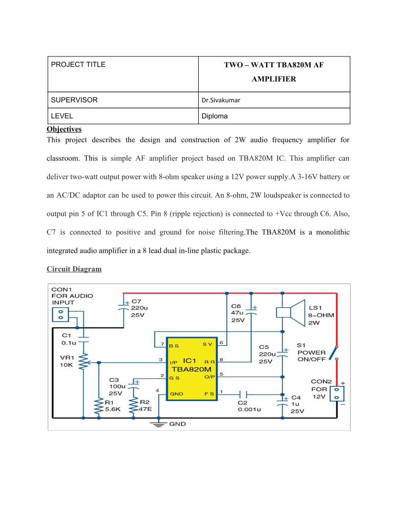
PROJECT TITLE TWO – WATT TBA820M AF
AMPLIFIER
SUPERVISOR Dr.Sivakumar
LEVEL Diploma
Objectives This project describes the design and construction of 2W audio frequency amplifier for
classroom. This is simple AF amplifier project based on TBA820M IC. This amplifier can
deliver two-watt output power with 8-ohm speaker using a 12V power supply.A 3-16V battery or
an AC/DC adaptor can be used to power this circuit. An 8-ohm, 2W loudspeaker is connected to
output pin 5 of IC1 through C5. Pin 8 (ripple rejection) is connected to +Vcc through C6. Also,
C7 is connected to positive and ground for noise filtering.The TBA820M is a monolithic
integrated audio amplifier in a 8 lead dual in-line plastic package.
Circuit Diagram
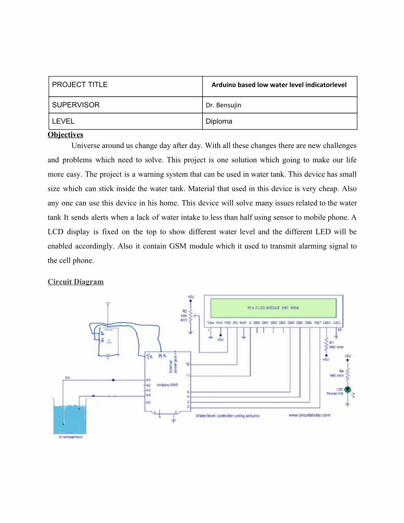
PROJECT TITLE Arduino based low water level indicatorlevel
SUPERVISOR Dr. Bensujin
LEVEL Diploma
Objectives Universe around us change day after day. With all these changes there are new challenges
and problems which need to solve. This project is one solution which going to make our life
more easy. The project is a warning system that can be used in water tank. This device has small
size which can stick inside the water tank. Material that used in this device is very cheap. Also
any one can use this device in his home. This device will solve many issues related to the water
tank It sends alerts when a lack of water intake to less than half using sensor to mobile phone. A
LCD display is fixed on the top to show different water level and the different LED will be
enabled accordingly. Also it contain GSM module which it used to transmit alarming signal to
the cell phone.
Circuit Diagram

A light operated internal door lock system can be implemented by controlling the rotation of a stepper motor on the application of light .This can be done by using a sensor which detects the presence of light and a control and driver circuit to operate the stepper motor suitably.
A light operated internal door lock system can be implemented by controlling the rotation of a stepper

motor on the application of light .This can be done by using a sensor which detects the presence of light and a control and driver circuit to operate the stepper motor suitably.
THIS ROBOT DETECTS AND FOLLOWS A BLACK LINE DRAWN ON A WHITE SURFACE.
AIM OF THIS PROJECT IS TO BUILD A SIMPLE LINE
FOLLOWING ROBOT USING .BASIC COMPONENTS

THIS ROBOT DETECTS AND FOLLOWS A BLACK LINE DRAWN ON A WHITE SURFACE.