Embed Size (px)
Citation preview

Project Planning Manual: Version 07
DOK-SYNAX*-SY*-07VRS**-PR01-EN-P
SYNAX200Decentralized System for the
Synchronization of Machine Axes

About this Documentation SYNAX200
DOK-SYNAX*-SY*-07VRS**-PR01-EN-P
SYNAX200
Decentralized System for the
Synchronization of Machine Axes
Project Planning Manual: Version 07
DOK-SYNAX*-SY*-07VRS**-PR01-EN-P
• Sy107E_O.doc
• Document Number 120-2200-B311-01/EN
This documentation assists
• in the selection of units and hardware components and
• in the basic control cabinet construction
Description ReleaseDate
Notes
DOK-SYNAX*-SY*-07VRS**-PR01-EN-P 05.00 Version 07VRS
2000 Rexroth Indramat GmbH
Copying this document, giving it to others and the use or communicationof the contents thereof without express authority, are forbidden. Offendersare liable for the payment of damages. All rights are reserved in the eventof the grant of a patent or the registration of a utility model or design (DIN34-1).
All rights are reserved with respect to the content of this documentationand the availability of the product.
Rexroth Indramat GmbHBgm.-Dr.-Nebel-Str. 2 • D-97816 Lohr a. Main
Telephone 09352/40-0 • Tx 689421 • Fax 09352/40-4885
http://www.rexroth.com/indramat
Dept. ESP (STS/TI)
This document has been printed on chlorine-free bleached paper..
Title
Type of Documentation
Document Typecode
Internal File Reference
Purpose of Documentation
Record of Revisions
Copyright
Validity
Published by
Note

SYNAX200 Contents I
DOK-SYNAX*-SY*-07VRS**-PR01-EN-P
Contents
1 Determing Drive and System Configurations 1-1
1.1 General........................................................................................................................................... 1-1
2 Important Directions for Use 2-1
2.1 Appropriate Use ............................................................................................................................. 2-1
Introduction .............................................................................................................................. 2-1
Areas of Use and Application................................................................................................... 2-2
2.2 Inappropriate Use........................................................................................................................... 2-2
3 Safety Instructions for Electric Servo Drives and Controls 3-1
3.1 Introduction..................................................................................................................................... 3-1
3.2 Explanations................................................................................................................................... 3-1
3.3 Hazards by Inappropriate Use ....................................................................................................... 3-2
3.4 General Information ....................................................................................................................... 3-3
3.5 Protection Against Contact with Electrical Parts ............................................................................ 3-4
3.6 Protection by Protective Low Voltage (PELV) Against Electrical Shock........................................ 3-6
3.7 Protection Against Dangerous Movements.................................................................................... 3-6
3.8 Protection Against Magnetic and Electromagnetic Fields During Operations and Mounting ........ 3-8
3.9 Protection Against Contact with Hot Parts ..................................................................................... 3-9
3.10 Protection During Handling and Installation................................................................................... 3-9
3.11 Battery Safety............................................................................................................................... 3-10
3.12 Protection Against Pressurized Systems..................................................................................... 3-10
4 PPC Motion Control Configuration 4-1
4.1 Brief Description............................................................................................................................. 4-1
4.2 Installation Dimensions .................................................................................................................. 4-2
PPC-R01.2 and PPC-R02.2..................................................................................................... 4-2
Installation dimensions of module carrier RMB02.2-02 ........................................................... 4-3
Installation dimensions of module carrier RMB02.2-04 ........................................................... 4-4
4.3 Installation Instructions................................................................................................................... 4-5
Installing the module carriers ................................................................................................... 4-5
Arrangement of the module carriers ........................................................................................ 4-5
Installing the modules .............................................................................................................. 4-5
Grounding ................................................................................................................................ 4-6
4.4 Slot Addressing of the Module Carriers ......................................................................................... 4-7
4.5 Combination Options Module Carrier - PPC - I/O Module ............................................................. 4-8
4.6 Specifications ................................................................................................................................. 4-9
General Information ................................................................................................................. 4-9

II Contents SYNAX200
DOK-SYNAX*-SY*-07VRS**-PR01-EN-P
Power supply............................................................................................................................ 4-9
Digital inputs and outputs......................................................................................................... 4-9
EMC ....................................................................................................................................... 4-10
Interfaces ............................................................................................................................... 4-10
4.7 Connecting the Power Supply...................................................................................................... 4-11
4.8 Connecting Inputs and Outputs ................................................................................................... 4-11
4.9 Connector Pin Assignments......................................................................................................... 4-12
X1 (11-way Phoenix female connector)................................................................................. 4-12
PROG / COM interface (X10, X16)........................................................................................ 4-12
BT bus (X15).......................................................................................................................... 4-13
4.10 Motion Control Configuration when Using the PPC-R ................................................................. 4-14
5 Determining Basic Drive Configuration 5-1
5.1 Procedure....................................................................................................................................... 5-1
a) Definition of Precision Requirements .................................................................................. 5-1
b) Selecting the Suitable Motor/Controller Combinations........................................................ 5-2
c) Determining the Drive Configuration Labelling .................................................................... 5-2
5.2 Rotary Axes.................................................................................................................................... 5-4
Drive with Step-Down Gear and Indirect Position Detection ................................................... 5-4
Drive with Step-Down Gears and Direct Incremental Position Detection................................ 5-6
Drive with Step-Down Gear and Direct Absolute Position Detection....................................... 5-8
Drive with Indirect Position Detection .................................................................................... 5-10
Drive with Direct Incremental Position Detection................................................................... 5-12
Drive with Direct Absolute Position Detection........................................................................ 5-14
5.3 Linear Axes .................................................................................................................................. 5-17
Drive with Indirect Position Detection .................................................................................... 5-17
Drive with Direct Incremental Position Detection................................................................... 5-19
Drive with Direct Absolute Position Detection........................................................................ 5-21
Drive with Linear Motor and Incremental Position Detection................................................. 5-23
Drive with Linear Motor and Absolute Position Detection...................................................... 5-25
6 Determining the Control-Related Plug-In Cards 6-1
6.1 Determining Parallel I/Os ............................................................................................................... 6-1
6.2 Combination Options of the External I/O (Drive Internal) .............................................................. 6-2
6.3 Determining the Master Axis .......................................................................................................... 6-3
6.4 Determining Analog Inputs............................................................................................................. 6-6
6.5 Master Axis Position Output........................................................................................................... 6-6
SSI Emulation .......................................................................................................................... 6-6
Incremental Encoder Emulation............................................................................................... 6-7
6.6 Encoder Branching DGA 01.2 for Encoders with Sinusoidal Voltage Signals 1Vss...................... 6-8
General .................................................................................................................................... 6-8
Terminal Diagram .................................................................................................................... 6-9
Technical Data ....................................................................................................................... 6-10
7 Drive Configurations 7-1
7.1 General Informations...................................................................................................................... 7-1
SYNAX200 Contents III
DOK-SYNAX*-SY*-07VRS**-PR01-EN-P
7.2 Drive Configurations DIAX03 Based on the Basic Configuration BE12 ........................................ 7-1
7.3 Drive Configurations DIAX03 Based on Basic Configuration BE32............................................... 7-3
7.4 Drive Configuration DIAX03 Based on Basic Configuration BE37 ................................................ 7-5
7.5 Drive Configuration DIAX03 Based on Basic Configuration BE45 ................................................ 7-7
7.6 Drive Configuration DIAX04 Based on Basic Configuration HS12 ................................................ 7-9
7.7 Drive Configuration DIAX04 Based on Basic Configuration HS32 .............................................. 7-11
7.8 Drive Configuration DIAX04 Based on Basic Configuration HS37 .............................................. 7-13
7.9 Drive Configuration DIAX04 Based on Basic Configuration HS45 .............................................. 7-15
7.10 Example ....................................................................................................................................... 7-17
Motion Control Configuration ................................................................................................. 7-17
Drive Configuration ................................................................................................................ 7-18
8 Set-Up SYNAX200 Ring 8-1
8.1 Data Transmission via Fibre-Optics Cable .................................................................................... 8-1
Optical Transmission Ring Structure ....................................................................................... 8-1
Constructing the Transmission Path........................................................................................ 8-2
Types of Fibre-Optics Cables .................................................................................................. 8-2
Fibre-Optics Cable Accessories............................................................................................... 8-3
8.2 Project Planning Notes................................................................................................................... 8-4
General Notes.......................................................................................................................... 8-4
Maximum Lengths of the Fibre-Optics Cables......................................................................... 8-4
Technical Data of Available Fibre-Optics Cables .................................................................... 8-4
General Safety Guidelines ....................................................................................................... 8-5
Handling ................................................................................................................................... 8-5
8.3 Set-Up ............................................................................................................................................ 8-6
Preparations............................................................................................................................. 8-6
Setting Drive Address .............................................................................................................. 8-8
Check Distortion Display.......................................................................................................... 8-8
8.4 Clearing Errors ............................................................................................................................... 8-8
Use of Distortion Display.......................................................................................................... 8-9
Setting the Transmission Rate................................................................................................. 8-9
Setting the Optic Output Power ............................................................................................. 8-11
Checking the Fibre-Optics Cables ......................................................................................... 8-11
9 PPC Link 9-1
9.1 General Information ....................................................................................................................... 9-1
9.2 PPC Link with Simple Ring ............................................................................................................ 9-2
9.3 PPC Link With Double Ring ........................................................................................................... 9-3
9.4 Configuration Example with PPC................................................................................................... 9-4
9.5 Commissioning the PPC Link ........................................................................................................ 9-4
General Information ................................................................................................................. 9-4
Commissioning ........................................................................................................................ 9-5
Clearing Errors......................................................................................................................... 9-5
10 Set-Up Interfaces 10-1
10.1 General Information ..................................................................................................................... 10-1

IV Contents SYNAX200
DOK-SYNAX*-SY*-07VRS**-PR01-EN-P
10.2 Connecting the PPC..................................................................................................................... 10-1
10.3 RS485 Link................................................................................................................................... 10-2
11 Appendix 11-1
11.1 Dimensional Sheets, Terminal Diagrams RECO ......................................................................... 11-1
Mounting Dimensions Module Carrier RMB02.2-02 .............................................................. 11-1
Mounting Dimensions Module Carrier RMB02.2-04 .............................................................. 11-2
PPC-R01.2 and PPC-R02.2................................................................................................... 11-3
DAQ03.1R.............................................................................................................................. 11-4
Profibus Interface DPS01 ...................................................................................................... 11-5
INTERBUS Interface IBS03................................................................................................... 11-6
DeviceNet Interface DNS03................................................................................................... 11-7
RME02.2-16-DC024 Input Module ........................................................................................ 11-8
RME02.2-32-DC024 Input Module ...................................................................................... 11-10
RME02.2-16-AC115 Input Module....................................................................................... 11-12
RMA02.2-16-DC024-200 Output Module ............................................................................ 11-14
RMA02.2-32-DC024-050 Output Module ............................................................................ 11-16
RMA02.2-16-AC230-200 Output Module............................................................................. 11-18
RMA02.2-16-RE230-200 Output Module............................................................................. 11-20
11.2 Dimensional Sheet, Terminal Diagrams Drives ......................................................................... 11-22
SERCOS interface DSS02.1M............................................................................................. 11-22
Input / Output interface DEA................................................................................................ 11-23
Encoder interface DAG01.2M (EnDat or SSI interface) ...................................................... 11-25
Analog interface with Actual Position Value Output DAE02.1M.......................................... 11-26
Absolute Encoder Emulator DSA01.1M............................................................................... 11-27
Position interface for Square-Wave Signals DEF01.1M...................................................... 11-28
Encoder interface DFF01.1M............................................................................................... 11-29
High-Resolution Position interface for Sinusoidal Signals DLF01.1M................................. 11-30
Gear Wheel Encoder interface DZF02.1M .......................................................................... 11-31
Gear Wheel Encoder interface DZF03.1M .......................................................................... 11-32
Dimensional Sheet DGA01.2 ............................................................................................... 11-33
List of Connectors and Ready-Made Cable......................................................................... 11-34
11.3 Supplementary Documentation.................................................................................................. 11-36
12 Index 12-1
13 Kundenbetreuungsstellen - Sales & Service Facilities 13-1

SYNAX200 Determing Drive and System Configurations 1-1
DOK-SYNAX*-SY*-07VRS**-PR01-EN-P
1 Determing Drive and System Configurations
1.1 GeneralSYNAX200 systems are built of up to 40 digital intelligent drives of theDIAX03 (DKR), DIAX04 and ECODRIVE03 drive family, a motion controlPPC-R, one LWL connection between these components meetingSERCOS interface standards (IEC 61491 or EN 61491) as well as anumber of optional plug-in cards for the digital intelligent drives and optionmodules for the PPC.
RECO
PPC-R01.2
H1
PR
OG
U2X10X1
I1
I3I2
Q1Q2
24Ve0VeBbBb24V0V
S1
RX
TX
U1RESETS2
H2DIST
PPC-R02.2PPC-R01.2
PPC-R02.2
H1
PR
OG
U2
X10X1
Q1Q2
24Ve0VeBbBb24V0V
S1
RX
TX
U1RESETS2
H2DIST
CO
MX16
U3 U4
I1
I3I2
RECO
Fig. 1-1: Motion control PPC-R

1-2 Determing Drive and System Configurations SYNAX200
DOK-SYNAX*-SY*-07VRS**-PR01-EN-P
Barc
ode
0 1
23
456
78
90 1
23
456
78
9
H1
S1
S3 S2
Barc
ode
Type
nsch
ild
12
34
56
78
91
23
4
111213141516
17185
67
8
12
34
56
78
XE2
XE1
L+
L-
L1
L2
L3
A1
A2
A3
Read and followInstructions for Electrical Drives"manual,DOK-GENERL-DRIVE******-SVS...
DANGHigh oltage.Danger of electrical shock.Do not touch electrical connectionsfor5 minutes after switching
ECODRIVE03
SY7PR102.FH7
DIAX04
U V W
Read and followInstructions for Electrical Drives"manual,DOK-GENERL-DRIVE******-SVS...
DANGHigh oltage.Danger of electrical shock.Do not touch electrical connectionsfo5 minutes after switching
U V W
Read and followInstructions for Electrical Drives"manual,DOK-GENERL-DRIVE******-SVS...
DANGHigh oltage.Danger of electrical shock.Do not touch electrical connectionsfo5 minutes after switching
Read and followInstructions for Electrical Drives"manual,DOK-GENERL-DRIVE******-SVS...
DANGHigh oltage.Danger of electrical shock.Do not touch electrical connectionsfo5 minutes after switching
HDD02.2
Read and followInstructions for Electrical Drives"manual,DOK-GENERL-DRIVE******-SVS...
DANGHigh oltage.Danger of electrical shock.Do not touch electrical connectionsfo5 minutes after switching
single axis unit double axis unit
DIAX03
Read and followInstructions for Electrical Drives"manual,DOK-GENERL-DRIVE******-SVS...
DANGHigh oltage.Danger of electrical shock.Do not touch electrical connectionsfo5 minutes after switching
HDS 04.2
Read and followInstructions for Electrical Drives"manual,DOK-GENERL-DRIVE******-SVS...
DANGHigh oltage.Danger of electrical shock.Do not touch electrical connectionsfo5 minutes after switching
HDS 03.2HDS 02.2
Read and followInstructions for Electrical Drives"manual,DOK-GENERL-DRIVE******-SVS...
DANGHigh oltage.Danger of electrical shock.Do not touch electrical connectionsfo5 minutes after switching
DKC**.3-040 DKC**.3-100
Bar
code
0 1
23
456
78
90 1
23
456
78
9
H1
S1
S3 S2
Read and followInstructions for Electrical Drives"manual,DOK-GENERL-DRIVE******-SVS...
DANGHigh oltage.Danger of electrical shock.Do not touch electrical connectionsfor5 minutes after switching
Barc
ode
Typenschild
12
34
56
78
91
23
4
1112
1314
1516
1718
56
78
10
Bar
code
0 1
23
456
78
90 1
23
456
78
9
H1
S1
S3 S2
Bar
code
Type
nsch
ild
12
34
56
78
91
23
4
1011
1213
141516
1718
56
78
Read and followInstructions for Electrical Drives"manual,DOK-GENERL-DRIVE******-SVS...
DANGHigh oltage.Danger of electrical shock.Do not touch electrical connectionsfor5 minutes after switching
DKC**.3-200
Read and followInstructions for Electrical Drives"manual,DOK-GENERL-DRIVE******-SVS...
DANGHigh oltage.Danger of electrical shock.Do not touch electrical connectionsfo5 minutes after switching
HDS 05.2
DKR 3.1 DKR 4.1DKR 2.1
DIGITAL COMPACT CONTROLLER DKR
220 VSteuer-
spannungAux.
Netz/Mains
L 3L 2L 1
Motor
A 3A 1 A 2 B2B1N L L+L-
H1
X4
X2
U5
U2
S2
U4
U1 U3
X9
1
6
1
7
X8
H2
S1
X3X7
1
10
1
1
X3
H1
X4
X2
U5
U2
S2
U4
U1 U3
X9
1
6
1
7
X8
H2
S1
X3X7
1
10
1
1
X3
DIGITAL COMPACT CONTROLLER DKR
Netz/Mains
L 3L 2L 1
Motor
A 3A 1 A 2 B2B1
220 VSteuerspannung
Aux.
N L K
X5
X10
TM+
TM-
BR
• • • •
X6
H1
X4
X2
U5
U2
S2
U4
U1 U3
X9
1
6
1
7
X8
H2
S1
X3X7
1
10
1
11
X3
Fig. 1-2: Drive controller
SYNAX200 Determing Drive and System Configurations 1-3
DOK-SYNAX*-SY*-07VRS**-PR01-EN-P
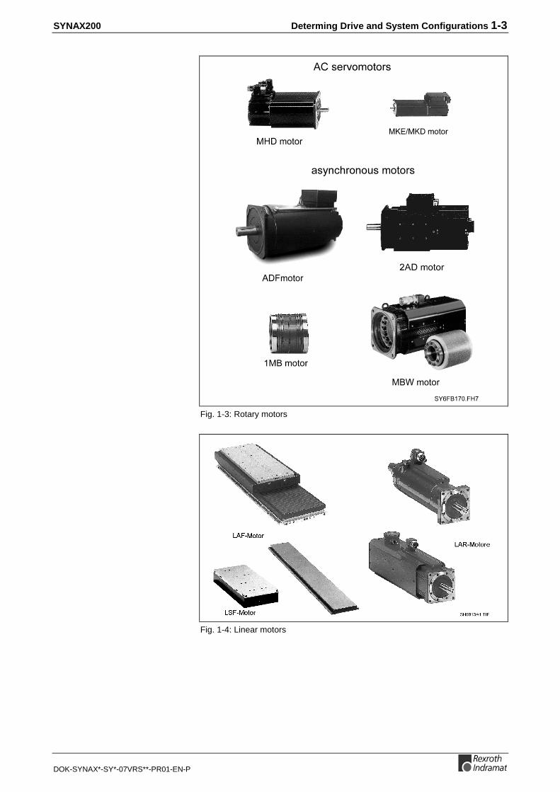
Fig. 1-3: Rotary motors
Fig. 1-4: Linear motors

1-4 Determing Drive and System Configurations SYNAX200
DOK-SYNAX*-SY*-07VRS**-PR01-EN-P
PPC Motion ControlThe motion control PPC can be adapted to meet numerous applicationrequirements by using various option modules.
The motion control itself is mounted on a module carrier. Module carriercan also be fitted with I/O modules.
PPCs not fitted with option modules are basic devices.
The following option modules are available:
• ARCNET-/PPC link assembly.
• Fieldbus modules.
This option module with designation DAQ serves for coupling of PPCsand serves for communication with higher automation level (e.g., SPS) viaARCNET interface.
Fieldbus slave interfaces are available for the fieldbusses Profibus (DPS),Interbus (IBS) and DeviceNet (DNS).
Note: The SYNAX200 system is adapted to the hardware on themachine in two steps:• First the drive concept in terms of the motor is
determined. This includes drive amplifiers and linearscale (as part of the basic drive configuration).
• Then PPC motion control function and plug-in cardassignment to the PPC motion controls is determined.
Basic devices
Option modules
ARCNET-/PPC link assembly
Fieldbus module

SYNAX200 Determing Drive and System Configurations 1-5
DOK-SYNAX*-SY*-07VRS**-PR01-EN-P
Read and followInstructions for Electrical Drives"manual,DOK-GENERL-DRIVE******-SVS...
DANGHigh oltage.Danger of electrical shock.Do not touch electrical connectionsfo5 minutes after switching
U V W
Read and followInstructions for Electrical Drives"manual,DOK-GENERL-DRIVE******-SVS...
DANGHigh oltage.Danger of electrical shock.Do not touch electrical connectionsfo5 minutes after switching
Read and followInstructions for Electrical Drives"manual,DOK-GENERL-DRIVE******-SVS...
DANGHigh oltage.Danger of electrical shock.Do not touch electrical connectionsfo5 minutes after switching
Read and followInstructions for Electrical Drives"manual,DOK-GENERL-DRIVE******-SVS...
DANGHigh oltage.Danger of electrical shock.Do not touch electrical connectionsfo5 minutes after switching
SY7PR001.FH7
PC, PLCmaster computerservice
SERCOS interfacefiber optics cable ring
PPC-R
PPC-R02.2
H1
PR
OG
U2
X10X1
Q1Q2
24Ve0VeBbBb24V0V
S1
RX
TX
U1RESETS2
H2DIST
CO
M
X16
U3 U4
I1
I3I2
RECO
Fig. 1-5: PPC configurations
PPC linkand/or
ARCNET coupling card
e.g. SPS
e.g. SPS
e.g. SPS
e.g. SPS
Profibusslave circuit
Interbusslave circuit
DeviceNetslave circuit
Fig. 1-6: Functional assignment of the PPC option modules with SYNAX200-system configuration

1-6 Determing Drive and System Configurations SYNAX200
DOK-SYNAX*-SY*-07VRS**-PR01-EN-P
MotorsAll rotary and linear motors which belong to the product line MKD, MKE,MHD, 2AD, 1MB, MBW, MBS, LAF and LSF can always be used.
Drive ControllerDigital drive controllers of the type DIAX03 (DKR) and DIAX04 can beadapted to meet numerous application requirements by using variousplug-in modules. For this reason, drive controllers are equipped with portsfor plug-in modules.
Digital drive controller of the type ECODRIVE03 are compact controllerwith integrated command interface card and evaluation interfaces. TheDIAX04 drive configuration described in this project planning are alsopossible with ECODRIVE03, but ECODRIVE03 has a reduced range ofcapacity.
Drive controllers not fitted with plug-in modules are basic devices.
The following plug-in modules are available:
• Command interface card module
• Modules for evaluating position measurement systems
• Input/output modules to evaluate SPS signals or to export signals tothe SPS
• Software modules
• Module for evaluating analog inputs
• Encoder emulation modules
The DSS plug-in module is used as a command interface card module.This module occupies in most cases slot U1 in the drive controller.
A basic device fitted with additional plug-in modules is called a configureddrive controller.
Every hardware configuration is designated by a letter/number sequence,e.g., HS04-01-FW. Digital drive controllers are delivered as configureddrive controllers which may be equipped with various components,according to the selected configuration.
The plug-in cards functionally assigned to the PPC motion control areaddressed directly via the SERCOS interface. The digital intelligent drivesthus fill a two-fold purpose. In addition to their intelligent drive functions,they also serve as a decentralized unit rack for the control-related plug-incards (see Fig. 1-6).
Only configured drive controllers are delivered for logistical reasons. Inother words, basic units or individual cards are only available for service.
Basic devices
Plug-in modules
Command interface card module
Configured drive controller
Hardware configuration

SYNAX200 Determing Drive and System Configurations 1-7
DOK-SYNAX*-SY*-07VRS**-PR01-EN-P
SY7PR048.FH7
high-resolutionmaster axis
encoder interface
DEAdigital inputand output
interface
DZFhigh-resolution
gear-toothencoder interface
DFFhigh-resolution
master axisencoder interface
DEA04/DEA08
DZF
DFF
Plug-in modules functionally assignedto the drives:
gear-tooth encoderrack-and-pinionencoder
SERCOSinterface
Plug-in modules functionally assignedto the PPC control unit:
e.g. PLC
fiber optic cable
travel limit switchreferencing switchmeasuring input
Interface module assigned to either the driveor the PPC control unit:
DSS
high-resolutiondigital servo
feedbackinterface
motor feedbackwith MHD, MKD
GDS 1.1
GDS 1.1X4
X4
master axisposition SSI-
output interfaceDSA SSI
EnDat/SSIencoderinterface Weg
SSI
SSIDAG
Weg
DLF high resolution
position interface
DLF
DEFposition interface forsquare-wave signals
DEFWeg
motor feedback ormaster axis encoder
EnDat
DAEanalogue interfacewith position valueoutput (only ELS5)
DAE+/- 10V analog
incrementalencoder emulation
DEAdigital inputand outputinterface
DEA05/DEA06/DEA09/DEA10
e.g. PLCdrive cam
Fig. 1-7: Functional assignment of the drive plug-in modules with SYNAX200system configuration

1-8 Determing Drive and System Configurations SYNAX200
DOK-SYNAX*-SY*-07VRS**-PR01-EN-P
SYNAX200 Important Directions for Use 2-1
DOK-SYNAX*-SY*-07VRS**-PR01-EN-P
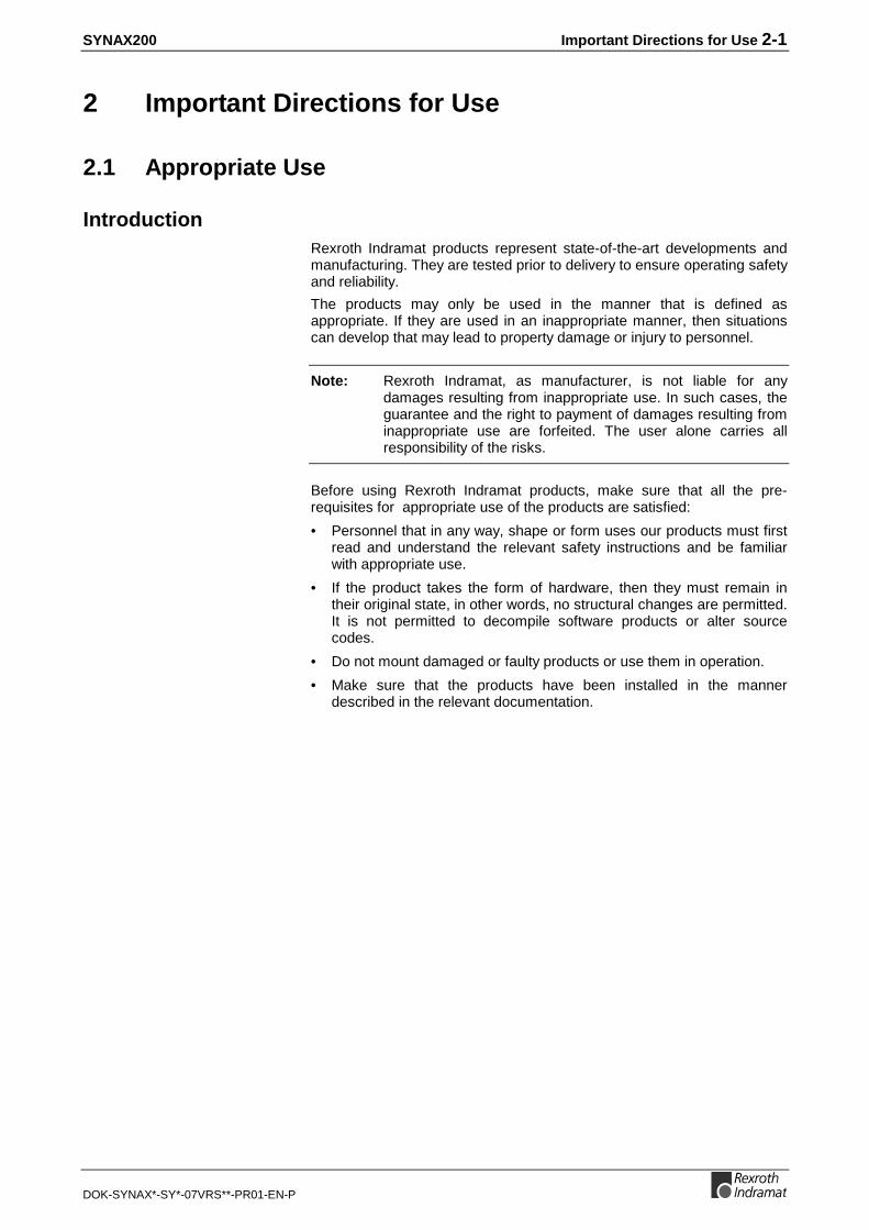
2 Important Directions for Use
2.1 Appropriate Use
IntroductionRexroth Indramat products represent state-of-the-art developments andmanufacturing. They are tested prior to delivery to ensure operating safetyand reliability.
The products may only be used in the manner that is defined asappropriate. If they are used in an inappropriate manner, then situationscan develop that may lead to property damage or injury to personnel.
Note: Rexroth Indramat, as manufacturer, is not liable for anydamages resulting from inappropriate use. In such cases, theguarantee and the right to payment of damages resulting frominappropriate use are forfeited. The user alone carries allresponsibility of the risks.
Before using Rexroth Indramat products, make sure that all the pre-requisites for appropriate use of the products are satisfied:
• Personnel that in any way, shape or form uses our products must firstread and understand the relevant safety instructions and be familiarwith appropriate use.
• If the product takes the form of hardware, then they must remain intheir original state, in other words, no structural changes are permitted.It is not permitted to decompile software products or alter sourcecodes.
• Do not mount damaged or faulty products or use them in operation.
• Make sure that the products have been installed in the mannerdescribed in the relevant documentation.

2-2 Important Directions for Use SYNAX200
DOK-SYNAX*-SY*-07VRS**-PR01-EN-P
Areas of Use and ApplicationSYNAX200 made by Rexroth Indramat is designed for thesynchronization of machine axes (shaftless machines).
Control and monitoring of the drive system may require additional sensorsand actors.
Note: The components may only be used with the accessories andparts specified in this document. If a component has not beenspecifically named, then it may not be either mounted orconnected. The same applies to cables and lines.
Operation is only permitted in the specified configurations andcombinations of components using the software and firmwareas specified in the relevant function descriptions.
The motion control and every drive controller has to be parametrized/programmed before starting it up, making it possible for the motor toexecute the specific functions of an application.
The motion control solution SYNAX200 has been developed for use insingle or multiple-axis drives and control tasks.
Typical applications of SYNAX200 are:
• printing and paper converting machines,
• textile machines,
• handling and assembly systems and
• packaging and foodstuff machines.
The motion control and drive system may only be operated under theassembly, installation and ambient conditions as described here(temperature, system of protection, humidity, EMC requirements, etc.)and in the position specified.
2.2 Inappropriate Use
Using the SYNAX200 components outside of the above-referenced areasof application or under operating conditions other than described in thedocument and the technical data specified is defined as “inappropriateuse".
The SYNAX200 components may not be used if
• they are subject to operating conditions that do not meet the abovespecified ambient conditions. This includes, for example, operationunder water, in the case of extreme temperature fluctuations orextremely high maximum temperatures or if
• Rexroth Indramat has not specifically released them for that intendedpurpose. Please note the specifications outlined in the general SafetyGuidelines!
SYNAX200 Safety Instructions for Electric Servo Drives and Controls 3-1
DOK-SYNAX*-SY*-07VRS**-PR01-EN-P
3 Safety Instructions for Electric Servo Drives andControls
3.1 Introduction
Read these instructions before the equipment is used and eliminate therisk of personal injury or property damage. Follow these safetyinstructions at all times.
Do not attempt to install, use or service this equipment without firstreading all documentation provided with the product. Read andunderstand these safety instructions and all user documentation of theequipment prior to working with the equipment at any time. If you do nothave the user documentation for your equipment contact your localRexroth Indramat representative to send this documentation immediatelyto the person or persons responsible for the safe operation of thisequipment.
If the product is resold, rented or transferred or passed on to others, thenthese safety instructions must be delivered with the product.
WARNING
Inappropriate use of this equipment, failure tofollow the safety instructions in this documentor tampering with the product, includingdisabling of safety devices, may result inproduct damage, personal injury, severeelectrical shock or death!
3.2 Explanations
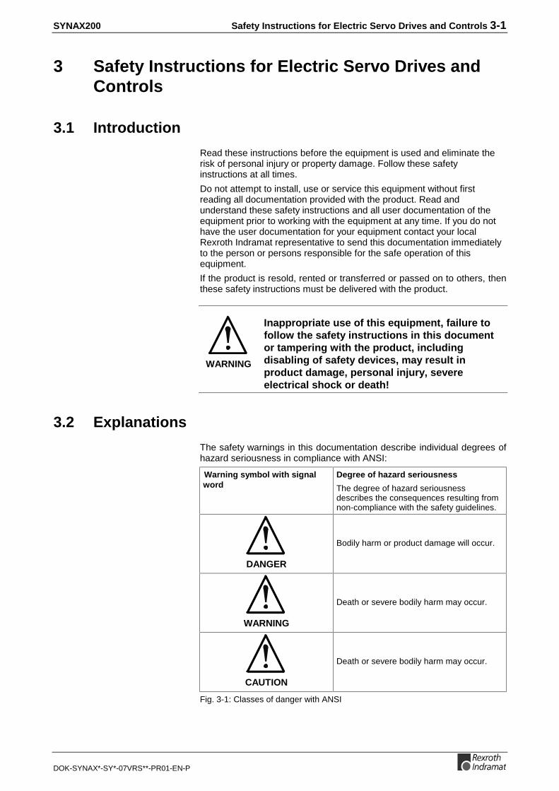
The safety warnings in this documentation describe individual degrees ofhazard seriousness in compliance with ANSI:
Warning symbol with signalword
Degree of hazard seriousness
The degree of hazard seriousnessdescribes the consequences resulting fromnon-compliance with the safety guidelines.
DANGER
Bodily harm or product damage will occur.
WARNING
Death or severe bodily harm may occur.
CAUTION
Death or severe bodily harm may occur.
Fig. 3-1: Classes of danger with ANSI

3-2 Safety Instructions for Electric Servo Drives and Controls SYNAX200
DOK-SYNAX*-SY*-07VRS**-PR01-EN-P
3.3 Hazards by Inappropriate Use
DANGER
High voltage and high discharge current!Danger to life, risk of severe electrical shockand risk of injury!
DANGER
Dangerous movements! Danger to life and riskof injury or equipment damage by unintentionalmotor movements!
WARNING
High electrical voltage due to wrongconnections! Danger to life, severe electricalshock and severe bodily injury!
WARNING
Health hazard for persons with heartpacemakers, metal implants and hearing aids inproximity to electrical equipment!
CAUTION
Surface of machine housing could be extremelyhot! Danger of injury! Danger of burns!
CAUTION
Risk of injury due to inappropriate handling!Bodily injury caused by crushing, shearing,cutting and mechanical shock or improperhandling of pressurized systems!
CAUTION
Risk of injury due to inappropriate handling ofbatteries!

SYNAX200 Safety Instructions for Electric Servo Drives and Controls 3-3
DOK-SYNAX*-SY*-07VRS**-PR01-EN-P
3.4 General Information
• Rexroth Indramat GmbH is not liable for damages resulting fromfailure to observe the warnings given in these documentation.
• Order operating, maintenance and safety instructions in your languagebefore starting up the machine. If you find that due to a translationerror you can not completely understand the documentation for yourproduct, please ask your supplier to clarify.
• Proper and correct transport, storage, assembly and installation aswell as care in operation and maintenance are prerequisites foroptimal and safe operation of this equipment.
• Trained and qualified personnel in electrical equipment:Only trained and qualified personnel may work on this equipment orwithin its proximity. Personnel are qualified if they have sufficientknowledge of the assembly, installation and operation of the productas well as an understanding of all warnings and precautionarymeasures noted in these instructions.Furthermore, they should be trained, instructed and qualified to switchelectrical circuits and equipment on and off, to ground them and tomark them according to the requirements of safe work practices andcommon sense. They must have adequate safety equipment and betrained in first aid.
• Only use spare parts and accessories approved by the manufacturer.
• Follow all safety regulations and requirements for the specificapplication as practiced in the country of use.
• The equipment is designed for installation on commercial machinery.
European countries: see directive 89/392/EEC (machine guideline).
• The ambient conditions given in the product documentation must beobserved.
• Use only safety features that are clearly and explicitly approved in theProject Planning manual.For example, the following areas of use are not allowed: Constructioncranes, Elevators used for people or freight, Devices and vehicles totransport people, Medical applications, Refinery plants, the transportof hazardous goods, Radioactive or nuclear applications, Applicationssensitive to high frequency, mining, food processing, Control ofprotection equipment (also in a machine).
• Start-up is only permitted once it is sure that the machine, in which theproduct is installed, complies with the requirements of national safetyregulations and safety specifications of the application.
• Operation is only permitted if the national EMC regulations for theapplication are met.The instructions for installation in accordance with EMC requirementscan be found in the INDRAMAT document "EMC in Drive and ControlSystems”.The machine builder is responsible for compliance with the limitingvalues as prescribed in the national regulations and specific EMCregulations for the application.
European countries: see Directive 89/336/EEC (EMC Guideline).
U.S.A.: See National Electrical Codes (NEC), National ElectricalManufacturers Association (NEMA), and local building codes. The user ofthis equipment must consult the above noted items at all times.
• Technical data, connections and operational conditions are specified inthe product documentation and must be followed at all times.

3-4 Safety Instructions for Electric Servo Drives and Controls SYNAX200
DOK-SYNAX*-SY*-07VRS**-PR01-EN-P
3.5 Protection Against Contact with Electrical Parts
Note: This section refers to equipment with voltages above 50 Volts.
Making contact with parts conducting voltages above 50 Volts could bedangerous to personnel and cause an electrical shock. When operatingelectrical equipment, it is unavoidable that some parts of the unit conductdangerous voltages.
DANGER
High electrical voltage! Danger to life, severeelectrical shock and severe bodily injury!⇒ Only those trained and qualified to work with or on
electrical equipment are permitted to operate,maintain or repair this equipment.
⇒ Follow general construction and safety regulationswhen working on electrical installations.
⇒ Before switching on power the ground wire must bepermanently connected to all electrical units accor-ding to the connection diagram.
⇒ Do not operate electrical equipment at any time if theground wire is not permanently connected, even forbrief measurements or tests.
⇒ Before working with electrical parts with voltagepotentials higher than 50 V, the equipment must bedisconnected from the mains voltage or powersupply.
⇒ The following should be observed with electricaldrives, power supplies, and filter components:Wait five (5) minutes after switching off power toallow capacitors to discharge before beginning work.Measure the voltage on the capacitors beforebeginning work to make sure that the equipment issafe to touch.
⇒ Never touch the electrical connection points of acomponent while power is turned on.
⇒ Install the covers and guards provided with theequipment properly before switching the equipmenton. Prevent contact with live parts at any time.
⇒ A residual-current-operated protective device (r.c.d.)must not be used on an electric drive! Indirectcontact must be prevented by other means, forexample, by an overcurrent protective device.
⇒ Equipment that is built into machines must besecured against direct contact. Use appropriatehousings, for example a control cabinet.
European countries: according to EN 50178/1998,section 5.3.2.3.
U.S.A: See National Electrical Codes (NEC), NationalElectrical Manufacturers Association (NEMA) and localbuilding codes. The user of this equipment must observethe above noted instructions at all times.

SYNAX200 Safety Instructions for Electric Servo Drives and Controls 3-5
DOK-SYNAX*-SY*-07VRS**-PR01-EN-P
To be observed with electrical drives, power supplies, and filtercomponents:
DANGER
High electrical voltage! High leakage current!Danger to life, danger of injury and bodily harmfrom electrical shock!⇒ Before switching on power for electrical units, all
housings and motors must be permanently groundedaccording to the connection diagram. This applieseven for brief tests.
⇒ Leakage current exceeds 3.5 mA. Therefore theelectrical equipment and units must always be firmlyconnected to the supply network.
⇒ Use a copper conductor with at least 10 mm² crosssection over its entire course for this protectiveconnection!
⇒ Prior to startups, even for brief tests, always connectthe protective conductor or connect with ground wire.High voltage levels can occur on the housing thatcould lead to severe electrical shock and personalinjury.
European countries: EN 50178/1998, section 5.3.2.1.
USA: See National Electrical Codes (NEC), NationalElectrical Manufacturers Association (NEMA), and localbuilding codes. The user of this equipment must maintainthe above noted instructions at all times.

3-6 Safety Instructions for Electric Servo Drives and Controls SYNAX200
DOK-SYNAX*-SY*-07VRS**-PR01-EN-P
3.6 Protection by Protective Low Voltage (PELV) AgainstElectrical Shock
All connections and terminals with voltages between 5 and 50 Volts onINDRAMAT products are protective low voltages designed in accordancewith the following standards on contact safety:
• International: IEC 364-4-411.1.5
• EU countries: see EN 50178/1998, section 5.2.8.1.
WARNING
High electrical voltage due to wrongconnections! Danger to life, severe electricalshock and severe bodily injury!⇒ Only equipment, electrical components and cables of
the protective low voltage type (PELV = ProtectiveExtra Low Voltage) may be connected to allterminals and clamps with 0 to 50 Volts.
⇒ Only safely isolated voltages and electrical circuitsmay be connected. Safe isolation is achieved, forexample, with an isolating transformer, an opto-electronic coupler or when battery-operated.
3.7 Protection Against Dangerous Movements
Dangerous movements can be caused by faulty control or the connectedmotors. These causes are be various such as:
• unclean or wrong wiring of cable connections
• inappropriate or wrong operation of equipment
• malfunction of sensors, encoders and monitoring circuits
• defective components
• software errors
Dangerous movements can occur immediately after equipment isswitched on or even after an unspecified time of trouble-free operation.
The monitors in the drive components make faulty operation almostimpossible. Regarding personnel safety, especially the danger of bodilyharm and property damage, this alone should not be relied upon toensure complete safety. Until the built-in monitors become active andeffective, it must be assumed in any case that some faulty drivemovements will occur. The extent of these faulty drive movementsdepends upon the type of control and the state of operation.

SYNAX200 Safety Instructions for Electric Servo Drives and Controls 3-7
DOK-SYNAX*-SY*-07VRS**-PR01-EN-P
DANGER
Dangerous movements! Danger to life and riskof injury or equipment damage!⇒ Personnel protection must be secured for the above
listed reason by means of superordinate monitors ormeasures.These are instituted in accordance with the specificsituation of the facility and a danger and faultanalysis conducted by the manufacturer of thefacility. All the safety regulations that apply to thisfacility are included therein. By switching off,circumventing or if safety devices have simply notbeen activated, then random machine movements orother types of faults can occur.
Avoiding accidents, injury or property damage:⇒ Keep free and clear of the machine’s range of
motion and moving parts. Prevent people fromaccidentally entering the machine’s range ofmovement:- use protective fences
- use protective railings
- install protective coverings
- install light curtains or light barriers
⇒ Fences must be strong enough to withstandmaximum possible momentum.
⇒ Mount the emergency stop switch (E-stop) in theimmediate reach of the operator. Verify that theemergency stop works before startup. Don’t operatethe machine if the emergency stop is not working.
⇒ Isolate the drive power connection by means of anemergency stop circuit or use a start-inhibit systemto prevent unintentional start-up.
⇒ Make sure that the drives are brought to standstillbefore accessing or entering the danger zone.
⇒ Secure vertical axes against falling or slipping afterswitching off the motor power by, for example:- Mechanically securing the vertical axes
- Adding an external brake / clamping mechanism
- Balancing and thus compensating for the verticalaxes mass and the gravitational force
The standard equipment motor brake or an externalbrake controlled directly by the servo drive are notsufficient to guarantee the safety of personnel!

3-8 Safety Instructions for Electric Servo Drives and Controls SYNAX200
DOK-SYNAX*-SY*-07VRS**-PR01-EN-P
⇒ Disconnect electrical power to the equipment using amaster switch and secure the switch againstreconnection for:- maintenance and repair work
- cleaning of equipment
- long periods of discontinued equipment use
⇒ Avoid operating high-frequency, remote control andradio equipment near electronics circuits and supplyleads. If use of such equipment cannot be avoided,verify the system and the plant for possiblemalfunctions at all possible positions of normal usebefore the first start-up. If necessary, perform aspecial electromagnetic compatibility (EMC) test onthe plant.
3.8 Protection Against Magnetic and Electromagnetic FieldsDuring Operations and Mounting
Magnetic and electromagnetic fields generated by current-carryingconductors and permanent magnets in motors represent a serious healthhazard to persons with heart pacemakers, metal implants and hearingaids.
WARNING
Health hazard for persons with heartpacemakers, metal implants and hearing aids inproximity to electrical equipment!⇒ Persons with pacemakers, metal implants and
hearing aids are not permitted to enter followingareas:- Areas in which electrical equipment and parts are
mounted, being operated or started up.
- Areas in which parts of motors with permanentmagnets are being stored, operated, repaired ormounted.
⇒ If it is necessary for a person with a pacemaker toenter such an area, then a physician must be con-sulted prior to doing so. Pacemaker, that are alreadyimplanted or will be implanted in the future, have aconsiderable deviation in their resistance tointerference. Due to the unpredictable behavior thereare no rules with general validity.
⇒ Persons with hearing aids, metal implants or metalpieces must consult a doctor before they enter theareas described above. Otherwise health hazardswill occur.

SYNAX200 Safety Instructions for Electric Servo Drives and Controls 3-9
DOK-SYNAX*-SY*-07VRS**-PR01-EN-P
3.9 Protection Against Contact with Hot Parts
CAUTION
Housing surfaces could be extremely hot!Danger of injury! Danger of burns!⇒ Do not touch surfaces near the source of heat!
Danger of burns!⇒ Wait ten (10) minutes before you access any hot
unit. Allow the unit to cool down.⇒ Do not touch hot parts of the equipment, such as
housings, heatsinks or resistors. Danger of burns!
3.10 Protection During Handling and Installation
Under certain conditions unappropriate handling and installation of partsand components may cause injuries.
CAUTION
Risk of injury through incorrect handling!Bodily harm caused by crushing, shearing,cutting and mechanical shock!⇒ Observe general instructions and safety regulations
during handling installation.⇒ Use only appropriate lifting or moving equipment.
⇒ Take precautions to avoid pinching and crushing.
⇒ Use only appropriate tools. If specified by the productdocumentation, special tools must be used.
⇒ Use lifting devices and tools correctly and safely.
⇒ Wear appropriate protective clothing, e.g. safetyglasses, safety shoes and safety gloves.
⇒ Never stay under suspended loads.
⇒ Clean up liquids from the floor immediately toprevent personnel from slipping.

3-10 Safety Instructions for Electric Servo Drives and Controls SYNAX200
DOK-SYNAX*-SY*-07VRS**-PR01-EN-P
3.11 Battery Safety
Batteries contain reactive chemicals in a solid housing. Inappropriatehandling may result in injuries or equipment damage.
CAUTION
Risk of injury through incorrect handling!⇒ Do not attempt to reactivate discharged batteries by
heating or other methods (danger of explosion andcorrosion).
⇒ Never charge batteries (danger from leakage andexplosion).
⇒ Never throw batteries into a fire.
⇒ Do not dismantle batteries.
⇒ Handle with care. Incorrect extraction or installationof a battery can damage equipment.
Note: Environmental protection and disposal! The batteriescontained in the product should be considered as hazardousmaterial for land, air and sea transport in the sense of the legalrequirements (danger of explosion). Dispose batteriesseparately from other refuse. Observe the legal requirementsgiven in the country of installation.
3.12 Protection Against Pressurized Systems
Certain Motors (ADS, ADM, 1MB etc.) and drives, corresponding to theinformation in the Project Planning manual, must be provided with andremain under a forced load such as compressed air, hydraulic oil, coolingfluid or coolant. In these cases, improper handling of the supply of thepressurized systems or connections of the fluid or air under pressure canlead to injuries or accidents.
CAUTION
Danger of injury when pressurized systems arehandled by untrained personnel!⇒ Do not attempt to disassemble, to open or to cut a
pressurized system.⇒ Observe the operation restrictions of the respective
manufacturer.⇒ Before the disassembly of pressurized systems,
lower pressure and drain off the fluid or gas.⇒ Use suitable protective clothing (for example
protective eyewear, safety shoes and gloves)⇒ Remove any fluid that has leaked out onto the floor
immediately.
Note: Environmental protection and disposal! The fluids used in theoperation of the pressurized system equipment is notenvironmentally compatible. Fluid that is damaging to theenvironment must be disposed of separate from normal waste.Observe the national specifications of the country ofinstallation.

SYNAX200 PPC Motion Control Configuration 4-1
DOK-SYNAX*-SY*-07VRS**-PR01-EN-P
4 PPC Motion Control Configuration
4.1 Brief Description
121212
7
5
3
4
1
28
9
11
10 6
13
5
7
6
3
4
1
2
13 12
10
11
9
8
PPC-R02.2PPC-R01.2
8
7
13
12
11
10
9
6
5
4
3
2
11 Key for display switchoveror other usageSlot for the PC card-compatiblefirmware moduleReset key S2
Distortion display H2for SERCOS interfaceFibre-optic emitterfor SERCOS interfaceFibre-optic receiverfor SERCOS interfaceX1 voltage supply andwatchdogStatus display H1
Optional slot
X16 Programming interface (COM)
X10 Serial interface (PROG)
Earthing bolt
X15 BT bus for connectingup to 6 devices (PLC only)
PPC-R01.2
H1
PR
OG
U2X1
I1
I3I2
Q1Q2
24Ve0VeBbBb24V0V
S1
RX
TX
U1RESET
H2DIST
COM
X16
S2
X10
PPC-R02.2
H1
PR
OG
U2
X10X1
Q1Q2
24Ve0VeBbBb24V0V
S1
RX
TX
U1RESET
H2DIST
CO
M
X16
U3 U4
I1
I3I2
S2
RECO RECO
Vorstellung.FH7
Fig. 4-1: PPC-R01.2 and PPC-R02.2
The PPC-R unit is a powerful controller in a small size in IP 20 rating. It isa general-purpose platform that works as a PLC or as an NC controller,depending on the application and the loaded software.
The PPC-R unit exists with two enclosure versions of different width. Asingle-width version and a double-width version.
The two interfaces that are available on the controller are fully connectedaccording to the Indramat standard (SIS = Serial Indramat Interface). Thedata transfer type (function) is only selected by the related application(RS232/RS422/RS485). With PPC-R01, the COM interface is brought outvia a separate slot plate if this has not yet been assigned for a differentpurpose (by the PC/104 Field bus, for example).
Furthermore, the PPC-R unit has a BT bus (operator input terminal bus)that permits application-related operator input terminals (BTM15/16,BTA20, etc.) to be used. This is possible with a cable length of up to 50m.
To install the PPC-R unit, a module carrier system is used that consists ofone or more RMB02.2-04 units. The double carrier RMB02.2-02 can onlybe used as an installation carrier. It is merely used for fixing the PPC-Runits; RECO modules cannot be controlled. Interconnecting several PPC-R units via a backplane is not possible either.
The PPC-R01.2 unit occupies one slot in the module carrier; the PPC-R02.2 occupies two units. In this carrier system, the PPC-R unit canhandle up to 15 further I/O modules (RME02.2..., RMA02.2... orRMC02.2...).
Depending on the application, the PPC-R has PC/104 modules fitted that,for example, can be used for open field bus interfaces, such as Interbus,Profibus, etc.

4-2 PPC Motion Control Configuration SYNAX200
DOK-SYNAX*-SY*-07VRS**-PR01-EN-P
4.2 Installation Dimensions
PPC-R01.2 and PPC-R02.2
PPC-R02.2PPC-R01.2
22 126,5
165
41,5 83,7 4,5
192
214
11
RECO
PPC-R01.2
H1
PR
OG
U2X10X1
I1
I3I2
Q1Q2
24Ve0VeBbBb24V0V
S1
RX
TX
U1RESETS2
H2DIST
PPC-R02.2
H1P
RO
G
U2
X10X1
Q1Q2
24Ve0VeBbBb24V0V
S1
RX
TX
U1RESETS2
H2DIST
CO
M
X16
U3 U4
I1
I3I2
RECO
Bemaßung.FH7
Fig. 4-2: Dimensioned drawing PPC-R01.2 and PPC-R02.2

SYNAX200 PPC Motion Control Configuration 4-3
DOK-SYNAX*-SY*-07VRS**-PR01-EN-P
ca. 235
ca. 300
56,5
2
247,
55
40,5
5
54,5
1515
ca. 183
RMB
Mounting railTS 35 x 27 x 15
Bemaßung_Einbau.FH7
Fig. 4-3: Installation dimensions of PPC-R01.2 and PPC-R02.2
Installation dimensions of module carrier RMB02.2-02
9
12
4,5
2,25
98
42 42
217
120
47
77
Tophat rail
TS35 x27 x15
54.5
5672
Screw for lockingthe subrack onthe tophat rail
RMB02.2_Maß.FH7
Fig. 4-4: Module carrier RMB02.2-02

4-4 PPC Motion Control Configuration SYNAX200
DOK-SYNAX*-SY*-07VRS**-PR01-EN-P
Installation dimensions of module carrier RMB02.2-04
S1
182
42 121
217
120
47
77
Tophat railTS 35 x 27 x15
54,5
562 7
9
12
4,5
2,25
Screw for lockingthe subrack on thetophat rail
RMB02.2-04_Maß.FH7
Fig. 4-5: Module carrier RMB02.2-04
42
182
121
182
4712
0
217
182
S1 S1
RMB02.2-04+02-04_Maß.FH7
Fig. 4-6: Side-by-side installation of several RMB02.2-04 module carriers

SYNAX200 PPC Motion Control Configuration 4-5
DOK-SYNAX*-SY*-07VRS**-PR01-EN-P
4.3 Installation Instructions
The module carriers must first be installed before the PPC-R units can beinstalled. These module carriers are equipped with the PPC-R unit and,according to the requirements, with the related I/O modules (RECO02modules).
Installing the module carriersTo install the RMB02.2-04 module carrier, you must latch it onto a DIN railTS 35x27x15 and secure it with a retaining screw. The module carriermay also be installed directly on the installation plate in the controlcabinet. This is done through boreholes provided in the module carrier(Fig. 4-5).
Up to four RMB02.2-04 module carriers can be installed side by side. ThePPC-R must be in slot 0 if it shall be able to control the RECO bus. Slotaddressing requires the DIP switches on the bus boards of the RMB02.2-04 module carriers to be configured (Fig. 4-9). The dual carrier RMB02.2-02 is used if the PCR-R shall be used on its own without RECO bus.
Arrangement of the module carriers
4x RMB02.2-04with a total of 16 module slots for
accommodating PPC-R and up to 15different I/O modules
RMB02.2-04_Anord.FH7
Fig. 4-7: Maximum configuration RMB02.2-04
Installing the modulesStarting with a PPC-R in slot 0 (left-hand side), the modules are pluggedinto the RMB02.2-04 module carrier. Each module is secured with twofixing screws. The I/O modules (RECO02.2) are added in the slots 1-15or 2-15 (with PPC-R02.2) to the right-hand side of the PPC-R. You mayleave gaps to be able to install additional modules later.
Note: Prior to commissioning, you must tighten the fixing screws ofthe module carriers in order to avoid lateral movements thatmay lead to a disconnection of the connectors. (The locationof the screws is shown in Fig. 4-5). The modules must bescrewed to the module carrier.

4-6 PPC Motion Control Configuration SYNAX200
DOK-SYNAX*-SY*-07VRS**-PR01-EN-P
GroundingGrounding the controller and screening the electronic componentsrequires a grounding cable of at least 6mm² to be laid between thegrounding stud of the controller to the central grounding point of themachine. The other devices of the machine must be grounded in a star-shaped configuration (see Fig. 4-8). The power supply must be groundedin the same way.
PP
C-R
MT
S-R
I/O I/O PP
C-R
I/O I/OI/O Driv
e
Driv
e
Driv
e
Centralgrounding pointof the machine
Machine op.terminal
Visualization
Devices MUST be connectedto the earthing bolt!
PPC-R_Erdung.FH7
Fig. 4-8: System grounding with PPC-R

SYNAX200 PPC Motion Control Configuration 4-7
DOK-SYNAX*-SY*-07VRS**-PR01-EN-P
4.4 Slot Addressing of the Module Carriers
A maximum of 4 module carriers RMB02.2-04 can be installed side byside. To be able to address the module carriers, there is a DIP switch onthe bus board of the module carriers. Depending on the module carrier,the switch must be set to the corresponding module carrier number(module carrier address 00-03, see diagram below). Each module carriernumber may only be set once.
S1S1 S1S1
Slot
Setting for basiccarrier No. 1
Setting for basiccarrier No. 2
Setting for basiccarrier No. 4
Setting for basiccarrier No. 3
S1 S1 S1 S1
00 01 02 03 04 05 06 07 08 09 10 11 12 13 14 15
RMB02.2_Adress.FH7
Fig. 4-9: Setting the slot address
4-8 PPC Motion Control Configuration SYNAX200
DOK-SYNAX*-SY*-07VRS**-PR01-EN-P
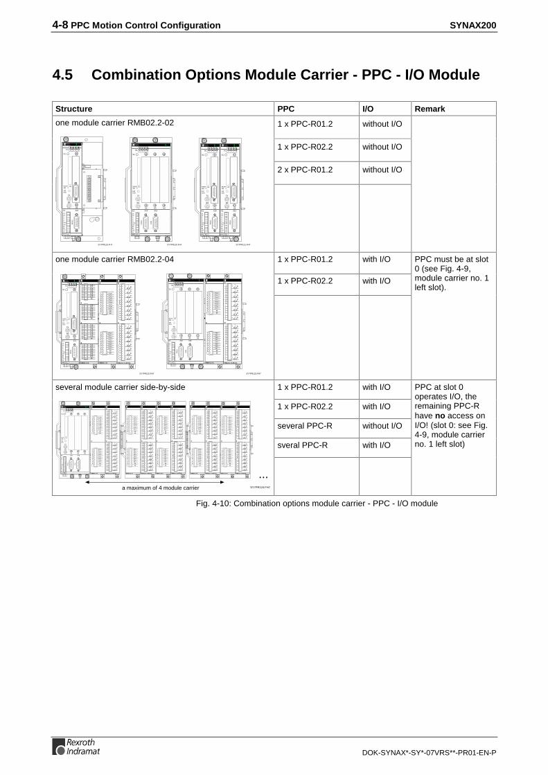
4.5 Combination Options Module Carrier - PPC - I/O Module
Structure PPC I/O Remark
1 x PPC-R01.2 without I/O
1 x PPC-R02.2 without I/O
2 x PPC-R01.2 without I/O
one module carrier RMB02.2-02
SY7PR119.FH7
RECO
PPC-R01.2
H1
PR
OG
U2X10X1
I1
I3I2
Q1Q2
24Ve0VeBbBb24V0V
S1
RX
TX
U1RESETS2
H2DIST
SY7PR120.FH7
PPC-R02.2
H1
PR
OG
U2
X10X1
Q1Q2
24Ve0VeBbBb24V0V
S1
RX
TX
U1RESETS2
H2DIST
CO
M
X16
U3 U4
I1
I3I2
RECO
SY7PR121.FH7
RECO
PPC-R01.2
H1
PR
OG
U2X10X1
I1
I3I2
Q1Q2
24Ve0VeBbBb24V0V
S1
RX
TX
U1RESETS2
H2DIST
RECO
PPC-R01.2
H1
PR
OG
U2X10X1
I1
I3I2
Q1Q2
24Ve0VeBbBb24V0V
S1
RX
TX
U1RESETS2
H2DIST
1 x PPC-R01.2 with I/O
1 x PPC-R02.2 with I/O
one module carrier RMB02.2-04
SY7PR122.FH7
S1
RECO
PPC-R01.2
H1
PR
OG
U2X10X1
I1
I3I2
Q1Q2
24Ve0VeBbBb24V0V
S1
RX
TX
U1RESETS2
H2DIST
SY7PR123.FH7
S1
PPC-R02.2
H1
PR
OG
U2
X10X1
Q1Q2
24Ve0VeBbBb24V0V
S1
RX
TX
U1RESETS2
H2DIST
CO
M
X16
U3 U4
I1
I3I2
RECO
PPC must be at slot0 (see Fig. 4-9,module carrier no. 1left slot).
1 x PPC-R01.2 with I/O
1 x PPC-R02.2 with I/O
several PPC-R without I/O
sveral PPC-R with I/O
several module carrier side-by-side
SY7PR124.FH7
S1 S1 S1
...
PPC-R02.2
H1
PR
OG
U2
X10X1
Q1Q2
24Ve0VeBbBb24V0V
S1
RX
TX
U1RESETS2
H2DIST
CO
M
X16
U3 U4
I1
I3I2
RECO
a maximum of 4 module carrier
PPC at slot 0operates I/O, theremaining PPC-Rhave no access onI/O! (slot 0: see Fig.4-9, module carrierno. 1 left slot)
Fig. 4-10: Combination options module carrier - PPC - I/O module

SYNAX200 PPC Motion Control Configuration 4-9
DOK-SYNAX*-SY*-07VRS**-PR01-EN-P
4.6 Specifications
General Information
Cable cross section of
Power supply feeder:
0.75 mm² to 1.5 mm²
Attachment in the control cabinet: with RMB02.2 module carrier on DIN rail TS 35 x 27 x 15
Protection rating: IP 20, EN 60529
Relative humidity: 5-85%, no condensation (operation)
5-95%, no condensation (transport)
Atmospheric pressure: 86-106 kPa
Operating temperature - environment: 0 to 45°C
Storage and transport temperature: -25°C to 70°C
Enclosure dimensions (B x H x T)
PPC-R01.1:
PPC-R02.1:
41,5 x 192 x 150
83.7 x 192 x 150
Weight: (PPC-R01/PPC-R02) 1.1kg / 1.3kg
Battery backup (only included if the optionalPPM memory module and the real-time clockare used)
To be replaced every year
Battery type Order name: Battery Lithium 3.5 V, preassembled
Fig. 4-11: General specifications
Power supply
Supply / rated voltage: 24 VDC -15% +20% to EN61131-2: 1994
AC voltage component: 5% of the rated voltage
Absolute limits: 19.2 to 30 VDC, ripples included
Max. current consumption: (PPC-R01)
(PPC-R02)
0,7 A (+supply voltage for I/O modules up to 2.6 A)
1.2 A (+supply voltage for I/O modules up to 2.6 A)
Fig. 4-12: Power supply
Digital inputs and outputs
Digital inputs (X1) Current-sinking (to ground), floatingVi,Low = 0V...5V; Vi,High = 15V...30V
Digital outputs (X1) Rated current 0.5 A, floating, VOH,min = Uext -3Vdelay = 400µs max.
Watchdog relay NO contact Vn=24 V, Imax = 150mA
Fig. 4-13: Inputs and outputs

4-10 PPC Motion Control Configuration SYNAX200
DOK-SYNAX*-SY*-07VRS**-PR01-EN-P
EMC
Emitted interference to EN 55022 Class A (industrial environment)
Noise immunity to EN 61000-4-2 (ESD) Rating criterion B
Noise immunity to EN 61000-4-4 (burst) Rating criterion B
Noise immunity to EN 61000-5-5 (surge) Rating criterion B
Fig. 4-14: EMC data
Interfaces
Programming interface (PROG) RS232/RS422/RS485 (D-SUB, 15-way female connector), isolated
General serial interface (COM) RS232/RS422/RS485 (D-SUB, 15-way female connector)
BT bus Indramat BT bus (D-SUB, 9-way female connector)
Fig. 4-15: Interface specifications

SYNAX200 PPC Motion Control Configuration 4-11
DOK-SYNAX*-SY*-07VRS**-PR01-EN-P
4.7 Connecting the Power Supply
Note: Connector and modules may only be inserted or removedwhen the power is switched off.
9
8
7
6
5
1
2
10
11
3
4
0V
X1
Bb
+24VDC +/-20%
Bb
+24VDC
PPC-R
Power Supply Unit
0V
2x0,75 mm2
0V external
24V external
Dig. input 3
Dig. input 2
Dig. input 1
Dig. output 2
Dig. output 1
Earthingbolt
PPC-R_AnX1.FH7
Fig. 4-16: Connecting the power supply
4.8 Connecting Inputs and Outputs
9
8
7
6
5
1
2
10
11
3
4
0V
X1
Bb
+24VDC +/-20%
Bb
+24VDC
PPC-R
Power supply unit
0V
2x0.75 mm20V external
24V external
Dig. input 3
Dig. input 2
Dig. input 1
Dig. output 2
Dig. output 1
Earthing bolt
PPC-R_AnX1_EA.FH7
Fig. 4-17: Connecting inputs and outputs
4-12 PPC Motion Control Configuration SYNAX200
DOK-SYNAX*-SY*-07VRS**-PR01-EN-P
4.9 Connector Pin Assignments
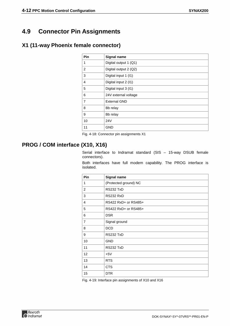
X1 (11-way Phoenix female connector)
Pin Signal name
1 Digital output 1 (Q1)
2 Digital output 2 (Q2)
3 Digital input 1 (I1)
4 Digital input 2 (I1)
5 Digital input 3 (I1)
6 24V external voltage
7 External GND
8 Bb relay
9 Bb relay
10 24V
11 GND
Fig. 4-18: Connector pin assignments X1
PROG / COM interface (X10, X16)Serial interface to Indramat standard (SIS – 15-way DSUB femaleconnectors).
Both interfaces have full modem capability. The PROG interface isisolated.
Pin Signal name
1 (Protected ground) NC
2 RS232 TxD
3 RS232 RxD
4 RS422 RxD+ or RS485+
5 RS422 RxD+ or RS485+
6 DSR
7 Signal ground
8 DCD
9 RS232 TxD
10 GND
11 RS232 TxD
12 +5V
13 RTS
14 CTS
15 DTR
Fig. 4-19: Interface pin assignments of X10 and X16

SYNAX200 PPC Motion Control Configuration 4-13
DOK-SYNAX*-SY*-07VRS**-PR01-EN-P
BT bus (X15)
PIN Signal name PIN Signal name
1 TxD+ 2 RxD+
3 GND 4 NC
5 +5V 6 TxD-
7 RxD- 8 NC
9 NC
Fig. 4-20: Connector pin assignments BT-BUS X15

4-14 PPC Motion Control Configuration SYNAX200
DOK-SYNAX*-SY*-07VRS**-PR01-EN-P
4.10 Motion Control Configuration when Using the PPC-R
Configuration designationDPS IBS DNS DAQ03 2nd serial
on slot plate
PPC-R01.2N-P1N-NN-FW
PPC-R01.2N-P1N-S1-FW X
PPC-R01.2N-P1N-P2-FW X
PPC-R01.2N-P1N-B4-FW X
PPC-R01.2N-P1N-V2-FW X
PPC-R01.2N-P1N-Q1-FW X
PPC-R02.2N-P1N-NN-NN-NN-FW
PPC-R02.2N-P1N-NN-P2-NN-FW X
PPC-R02.2N-P1N-Q1-P2-NN-FW X X
PPC-R02.2N-P1N-B2-NN-NN-FW X
PPC-R02.2N-P1N-Q1-B2-NN-FW X X
PPC-R02.2N-P1N-V2-NN-NN-FW X
PPC-R02.2N-P1N-Q1-V2-NN-FW X X
PPC-R02.2N-P1N-Q1-NN-NN-FW X
Fig. 4-21: Coonfiguration selection when using the PPC-R
DPS: PROFIBUS-DP Slave interface
IBS: INTERBUS-S Slave interface
DNS: DeviceNet Slave interface
DAQ: ARCNET Slave interface and PPC link interface card
2. ser:: Second serial interface on plug-in slot plate (only PPC-R01)

SYNAX200 Determining Basic Drive Configuration 5-1
DOK-SYNAX*-SY*-07VRS**-PR01-EN-P
5 Determining Basic Drive Configuration
5.1 Procedure
The drive configuration choices (motor, drive amplifier, drive-related plug-in cards) conform to the power requirements and the precisionrequirements of the respective drive task.
To determine the drive configuration or to specify the hardwareconfiguration labelling of a drive controller for the corresponding machine,we recommend the following procedure:
1. Determine the precision requirements:
- Select the required gearbox and linear scales.
2. Determine the motor/controller combination:
- Determine rpm/torque requirements for your purpose.
- Select motor/controller combination from the list.
3. Determine the drive configuration labelling:
- Select motor - motor feedback combination.
- Select desired features.
- Determine configuration labelling based on the plug-in modules required for the desired features.
a) Definition of Precision RequirementsA differentiation is made between absolute and relative precision(repetitive precision) as well as scale resolution. It depends primarily onthe mechanical transmission elements and the quality of the mountinglocation of the linear scale.
Motor type
Motor with gearbox and resolver as motor feedback
Motor with gearbox and DSF as motor feedback
Motor with gearbox and external encoder mountedloadside (direct position detection)
Conventional motor as direct drive and encoder loadside
Mounted motor and loadside encoder
Motor type
MKD
MKE2ADMHDADF
MKDMKE2ADMHDADF
MKDMKE2ADMHDADF
1MBMBWMBS
everincreasingprecision
SY7PR002.FH7
Fig. 5-1: Selection table for precision
5-2 Determining Basic Drive Configuration SYNAX200
DOK-SYNAX*-SY*-07VRS**-PR01-EN-P
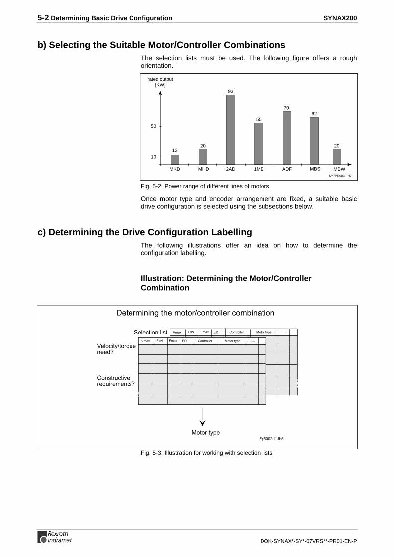
b) Selecting the Suitable Motor/Controller CombinationsThe selection lists must be used. The following figure offers a roughorientation.
SY7PR003.FH7
rated output[KW]
10
50
MKD
1220
2AD
93
1MB
55
MBWMHD ADF
70
MBS
20
62
Fig. 5-2: Power range of different lines of motors
Once motor type and encoder arrangement are fixed, a suitable basicdrive configuration is selected using the subsections below.
c) Determining the Drive Configuration LabellingThe following illustrations offer an idea on how to determine theconfiguration labelling.
Illustration: Determining the Motor/ControllerCombination
!"#$!%%&$ !#!$#'(&
!"#$!%%&$ !#!$#'(&
&%!)*#'+#!$,-&"&& .
!"/#$-)#*0&$&,-*$&&"#/.
&#&$*"*"1#2&!#!$+)!"#$!%%&$)!3*"#*!"
&%&)#*!"%*/#
!#!$#'(&(45 624
Fig. 5-3: Illustration for working with selection lists

SYNAX200 Determining Basic Drive Configuration 5-3
DOK-SYNAX*-SY*-07VRS**-PR01-EN-P
Illustration: Determining the Hardware ConfigurationLabelling
Tab.: B4
Tab.: B3
Tab.: B2
DZF 2.1
Tab.: B1
DAG 1.2
Functionality:
Analog inputs
digital inputsand outputs
Neededplug-in module
Necessary plug-in modules:
DEA DEF 4.2 1.1
DAE DSA 2.1 1.1
Tab.: A
Sinefeedback
Sprocketfeedback
Motortype:
MKD
MHD
LSF
EnDatfeedback
Motor feedback interface:
1.1 Selection of motor- motor feedback combination
Example: MHD motor with DSF as motor interface
Example: additional functions selected: analog inputs > DAE 2.1 digital I/Os > DEA 4.2
Example:DAE 2.1 + DEA 4.2 > HS84-01-FW
Tab.: C4Tab.: C3
Tab.: C2
DZF 2.1
Tab.: C1
DAG 1.2
configuration -designation:
HS12-01-FW
HS30-01-FW
Modul combination:
DEA DEF DEF 4.2 1.1 2.1
DAE DSA 2.1 1.1
HS99-01-FW X
DEF 2.1
X
X
X
X
X
X X
X X
1. Determining the necessary plug-in modules
HS84-01-FW
2. Determining the configuration designation based on the selected plug-in modules
FP5006d1.fh7
1.2 Selection of desired functionality > determining the necessary additional plug-in modules
ResolverDig. servofeedback
X
X
Fig. 5-4: Illustration for determining configuration labelling

5-4 Determining Basic Drive Configuration SYNAX200
DOK-SYNAX*-SY*-07VRS**-PR01-EN-P
5.2 Rotary Axes
Drive with Step-Down Gear and Indirect Position Detection
• Precision is determined with gear error (generally four angle minutes)
• encoder is integrated into motor
• motor encoder with singleturn or multiturn absolute encoder
Usable Motors DKR:• 2AD with HSF (HSF: digital servo feedback)
• ADF with HSF
Basic Drive Configuration BE12 (DKR):
2ADADF
DIGITAL COMPACT CONTROLLER DKR 4
H1
X4
X2
U5
U2
S2
U4
U1 U3
X9
1
6
1
7
X8
H2
S1
X3X7
1
10
1
11
X3
IKS 374
reference switch
scale input
LWL
U1 (DSS)
SY7PR004.FH7
Fig. 5-5: Drive with step-down gears and indirect position detection
Features:
2AD with HSF, ADF with HSF

SYNAX200 Determining Basic Drive Configuration 5-5
DOK-SYNAX*-SY*-07VRS**-PR01-EN-P
Usable Motors DIAX04:• MHD
• MKD
• MKE
• 2AD with HSF
• ADF with HSF
• MBW
• 1MB
Basic Drive Configuration HS12 (DIAX04):
MHDMKEMKD2ADADFMBW1MB
Read and followInstructions for Electrical Drives"manual,DOK-GENERL-DRIVE******-SVS...
DANGHigh oltage.Danger of electrical shock.Do not touch electrical connectionsfo5 minutes after switching
IKS 4374 reference switch
scale input
LWL
U1 (DSS)
SY7PR082.FH7
Fig. 5-6: Drive with step-down gears and indirect position detection
MHD, MKE, MKD,2AD with HSF, ADF with HSF,
MBW, 1MB:

5-6 Determining Basic Drive Configuration SYNAX200
DOK-SYNAX*-SY*-07VRS**-PR01-EN-P
Drive with Step-Down Gears and Direct Incremental Position Detection
• Precision determined by gear error (generally four angle minutes)
• encoder is integrated into motor
• motor encoder single-turn encoder
• load angle directly detected via incremental external encoder
• gear error is statically compensated
Usable Motors DKR:• 2AD with HSF
• ADF with HSF
Basic Drive Configuration BE32 (DKR):
2ADADF
IKS 374
reference switch
scale input
LWL
U1 (DSS)
IKS 349
U2 (DLF)
external encoderwith sine output
e.g., HeidenhainROD 481ERN 180ERN 680RON 285
SY7PR005.FH7
DIGITAL COMPACT CONTROLLER DKR 4
H1
X4
X2
U5
U2
S2
U4
U1 U3
X9
1
6
1
7
X8
H2
S1
X3X7
1
10
1
11
X3
Fig. 5-7: Drive with step-down gear and direct incremental position detection
Feature:
2AD with HSF, ADF with HSF:

SYNAX200 Determining Basic Drive Configuration 5-7
DOK-SYNAX*-SY*-07VRS**-PR01-EN-P
Usable Motors DIAX04:• MHD
• MKD
• MKE
• 2AD with HSF
• ADF with HSF
Basic Drive Configuration HS32 (DIAX04):
MHDMKEMKD2ADADF
Read and followInstructions for Electrical Drives"manual,DOK-GENERL-DRIVE******-SVS...
DANGHigh oltage.Danger of electrical shock.Do not touch electrical connectionsfo5 minutes after switching
IKS 4374
reference switch
scale input
LWL
U1 (DSS)
U2 (DLF)
IKS 4383
SY7PR089.FH7
external encoderwith sine output
e.g., HeidenhainROD 481ERN 180ERN 680RON 285
Fig. 5-8: Drive with step-down gear and direct incremental position detection
MHD, MKD, MKE,2AD with HSF, ADF with HSF:

5-8 Determining Basic Drive Configuration SYNAX200
DOK-SYNAX*-SY*-07VRS**-PR01-EN-P
Drive with Step-Down Gear and Direct Absolute Position Detection
• Precision is determined by gear error(generally four angle minutes)
• encoder is integrated into motor
• motor encoder multiturn absolute encoder
• load angle directly detected via absolute external encoder
• gear error statically compensated
Usable Motors DKR:• 2AD with HSF
• ADF with HSF
Basic Drive Configuration BE45 (DKR):
2ADADF
IKS 374
LWL
U1 (DSS)
IKS 349
U2 (DAG)
EnDat
EnDat encodere.g., Heidenhain
SY7PR049.FH7
DIGITAL COMPACT CONTROLLER DKR 4
H1
X4
X2
U5
U2
S2
U4
U1 U3
X9
1
6
1
7
X8
H2
S1
X3X7
1
10
1
11
X3
Fig. 5-9: Drive with step-down gear and direct absolute position detection
Feature:
2AD with HSF, ADF with HSF:

SYNAX200 Determining Basic Drive Configuration 5-9
DOK-SYNAX*-SY*-07VRS**-PR01-EN-P
Usable Motors DIAX04:• MHD
• MKD
• MKE
• 2AD with HSF
• ADF with HSF
Basic Drive Configuration HS45 (DIAX04):
MHDMKDMKE2ADADF
Read and followInstructions for Electrical Drives"manual,DOK-GENERL-DRIVE******-SVS...
DANGHigh oltage.Danger of electrical shock.Do not touch electrical connectionsfo5 minutes after switching
IKS 4374
LWL
U1 (DSS)
U2 (DAG)
IKS 4142
EnDat
SY7PR090.FH7
EnDat encodere.g., Heidenhain
Fig. 5-10: Drive with step-down gear and direct absolute position detection
MHD, MKD, MKE2AD with HSF, ADF with HSF:
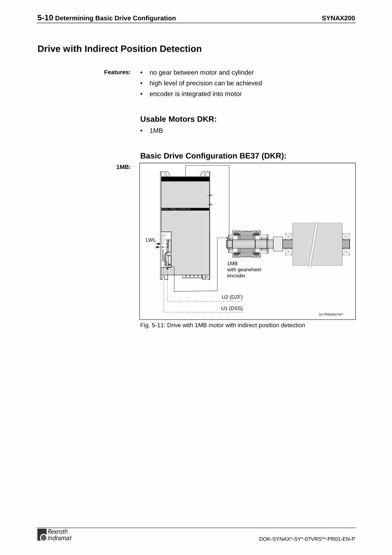
5-10 Determining Basic Drive Configuration SYNAX200
DOK-SYNAX*-SY*-07VRS**-PR01-EN-P
Drive with Indirect Position Detection
• no gear between motor and cylinder
• high level of precision can be achieved
• encoder is integrated into motor
Usable Motors DKR:• 1MB
Basic Drive Configuration BE37 (DKR):
SY7PR009.FH7
1MBwith gearwheelencoder
LWL
U1 (DSS)
U2 (DZF)
DIGITAL COMPACT CONTROLLER DKR 4
H1
X4
X2
U5
U2
S2
U4
U1 U3
X9
1
6
1
7
X8
H2
S1
X3X7
1
10
1
11
X3
Fig. 5-11: Drive with 1MB motor with indirect position detection
Features:
1MB:

SYNAX200 Determining Basic Drive Configuration 5-11
DOK-SYNAX*-SY*-07VRS**-PR01-EN-P
Usable Motors DIAX04:• 1MB
Basic Drive Configuration HS37 (DIAX04):
1MBwith gearwheelencoder
Read and followInstructions for Electrical Drives"manual,DOK-GENERL-DRIVE******-SVS...
DANGHigh oltage.Danger of electrical shock.Do not touch electrical connectionsfo5 minutes after switching
LWL
U1 (DSS)
U2 (DZF)
SY7PR091.FH7
Fig. 5-12: Drive with 1MB motor with indirect position detection
1MB:

5-12 Determining Basic Drive Configuration SYNAX200
DOK-SYNAX*-SY*-07VRS**-PR01-EN-P
Drive with Direct Incremental Position Detection
• no gear between motor and cylinder
• high level of precision can be achieved
• load angle directly determined via incremental external encoder
• gear error statically compensated
• With MHD, MKE, MKD and MBS motors:- motor encoder for commutation is needed- absolute position detection via motor encoder
• With MBW, 1MB, 2AD and ADF motors:- no separate motor encoder- no absolute position detection
• With MBW and 1MB motors:- rigid coupling between motor and cylinder, resulting in
highest level of static and dynamic stiffness
Usable Motors DKR:• MBW (without motor encoder)
• 1MB (without motor encoder)
• 2AD (without motor encoder)
• ADF (without motor encoder)
• MBS (only in connection with motor encoder)
Basic Drive Configuration BE32 (DKR)
SY7PR006.FH7
MBW2ADADF1MB
LWL
U1 (DSS)
U2 (DLF)
IKS 349
DIGITAL COMPACT CONTROLLER DKR 4
H1
X4
X2
U5
U2
S2
U4
U1 U3
X9
1
6
1
7
X8
H2
S1
X3X7
1
10
1
11
X3
externalincremental encoder
with sine outpute.g., Heidenhain
ROD 481ERN 180ERN 680RON 285
Fig. 5-13: Drive with MBW, 2AD or 1MB motor with direct incremental positiondetection
Features:
MBW, 2AD, ADF, 1MB:

SYNAX200 Determining Basic Drive Configuration 5-13
DOK-SYNAX*-SY*-07VRS**-PR01-EN-P
Basic Drive Configuration BE32 (DKR):
SY7PR007.FH7
MBS
LWL
U1 (DSS)
U2 (DLF)
IKS 349
IKS 374
DIGITAL COMPACT CONTROLLER DKR 4
H1
X4
X2
U5
U2
S2
U4
U1 U3
X9
1
6
1
7
X8
H2
S1
X3X7
1
10
1
11
X3
externalincremental encoder
with sine outpute.g., Heidenhain
ROD 481ERN 180ERN 680RON 285
Fig. 5-14: Drive with MBS motor with direct incremental position detection
Usable Motors DIAX04:• MBW (without motor encoder)
• 1MB (without motor encoder)
• 2AD (without motor encoder)
• ADF (without motor encoder)
• MHD (only in connection with motor encoder)
• MKD (only in connection with motor encoder)
• MKE (only in connection with motor encoder)
• MBS (only in connection with motor encoder)
Basic Drive Configuration HS32 (DIAX04)
Read and followInstructions for Electrical Drives"manual,DOK-GENERL-DRIVE******-SVS...
DANGHigh oltage.Danger of electrical shock.Do not touch electrical connectionsfo5 minutes after switching
LWL
U1 (DSS)
U2 (DLF)
MBW2ADADF1MB
IKS4383
SY7PR092.FH7
externalincremental encoder
with sine outpute.g., Heidenhain
ROD 481ERN 180ERN 680RON 285
Fig. 5-15: Drive with MBW, 2AD, ADF or 1MB motor with direct incrementalposition detection
MBS:
MBW, 2AD, ADF, 1MB:

5-14 Determining Basic Drive Configuration SYNAX200
DOK-SYNAX*-SY*-07VRS**-PR01-EN-P
Basic Drive Configuration HS32 (DIAX04):
Read and followInstructions for Electrical Drives"manual,DOK-GENERL-DRIVE******-SVS...
DANGHigh oltage.Danger of electrical shock.Do not touch electrical connectionsfo5 minutes after switching
LWL
U1 (DSS)
U2 (DLF)
MHDMKDMKEMBS
IKS4383
IKS374
SY7PR093.FH7
externalincremental encoder
with sine outpute.g., Heidenhain
ROD 481ERN 180ERN 680RON 285
Fig. 5-16: Drive with MHD, MKD, MKE or MBS motor with direct incrementalposition detection
Drive with Direct Absolute Position Detection
• no gear between motor and cylinder
• high level of precision an be achieved
• load angle directly detected via absolute external encoder
• gear error statically compensated
• With MHD, MKD, MKE and MBS motors:- motor encoder for commutation is needed- absolute position detection via external encoder
• With MBW, 1MB, 2AD and ADF motors:- no separate motor encoder- absolute position detection
• With MBW, MBS and 1MB motors:- rigid coupling between motor and cylinder, meaning highest
level of static and dynamic stiffness
Usable Motors DKR:• MBW (without motor encoder)
• 1MB (without motor encoder)
• 2AD (without motor encoder)
• ADF (without motor encoder)
• MBS (only in connection with motor encoder)
MHD, MKD, MKE, MBS:
Features:

SYNAX200 Determining Basic Drive Configuration 5-15
DOK-SYNAX*-SY*-07VRS**-PR01-EN-P
Basic Drive Configuration BE45 (DKR):
SY7PR0051.FH7
MBW2ADADF1MB
LWL
U1 (DSS)
U2 (DAG)
EnDat
EnDat encodere.g., Heidenhain
DIGITAL COMPACT CONTROLLER DKR 4
H1
X4
X2
U5
U2
S2
U4
U1 U3
X9
1
6
1
7
X8
H2
S1
X3X7
1
10
1
11
X3
Fig. 5-17: Drive with MBW, 2AD, ADF or 1MB motor with direct absolute positiondetection
Basic Drive Configuration BE32 (DKR):
SY7PR0052.FH7
MBS
LWL
U1 (DSS)
U2 (DAG)
EnDat
EnDat encodere.g., Heidenhain
IKS 374
DIGITAL COMPACT CONTROLLER DKR 4
H1
X4
X2
U5
U2
S2
U4
U1 U3
X9
1
6
1
7
X8
H2
S1
X3X7
1
10
1
11
X3
Fig. 5-18: Drive with MBS motor with direct absolute position detection
MBW, 2AD, ADF, 1MB:
MBS:

5-16 Determining Basic Drive Configuration SYNAX200
DOK-SYNAX*-SY*-07VRS**-PR01-EN-P
Usable Motors DIAX04:• MBW (without motor encoder)
• 1MB (without motor encoder)
• 2AD (without motor encoder)
• ADF (without motor encoder)
• MHD (only in connection with motor encoder)
• MKD (only in connection with motor encoder)
• MKE (only in connection with motor encoder)
• MBS (only in connection with motor encoder)
Basic Drive Configuration HS45 (DIAX04):
Read and followInstructions for Electrical Drives"manual,DOK-GENERL-DRIVE******-SVS...
DANGHigh oltage.Danger of electrical shock.Do not touch electrical connectionsfo5 minutes after switching
LWL
U1 (DSS)
U2 (DAG)
MBW2ADADF1MB
IKS4142
SY7PR094.FH7
EnDat encodere.g., Heidenhain
EnDat
Fig. 5-19: Drive with MBW, 2AD, ADF or 1MB motor with direct absolute positiondetection
Basic Drive Configuration HS32 (DIAX04):
Read and followInstructions for Electrical Drives"manual,DOK-GENERL-DRIVE******-SVS...
DANGHigh oltage.Danger of electrical shock.Do not touch electrical connectionsfo5 minutes after switching
LWL
U1 (DSS)
U2 (DAG)
MHDMKDMKEMBS
IKS 4374
IKS 4142
SY7PR095.FH7
EnDat encodere.g., Heidenhain
EnDat
Fig. 5-20: Drive with MHD, MKD, MKE or MBS motor with direct absolute positiondetection
MBW, 2AD, ADF, 1MB:
MHD, MKD, MKE, MBS:

SYNAX200 Determining Basic Drive Configuration 5-17
DOK-SYNAX*-SY*-07VRS**-PR01-EN-P
5.3 Linear Axes
Drive with Indirect Position Detection
• accuracy determined by spindle and gear errors
• encoder is integrated into motor
• motor encoder either with singleturn or multiturn absolute encoder
Usable Motors DKR:• 2AD with HSF
• ADF with HSF
Basic Drive Configuration BE12 (DKR):
pos. travel range limit switch
neg. travel range limit switch
scale inputU1 (DSS)
SY7PR008.FH7
2ADADF
reference switch
slide
LWL
DIGITAL COMPACT CONTROLLER DKR 4
H1
X4
X2
U5
U2
S2
U4
U1 U3
X9
1
6
1
7
X8
H2
S1
X3X7
1
10
1
11
X3
Fig. 5-21: Drive with 2AD or ADF motor with DSF and indirect position detection
Features:
2AD with HSF, ADF with HSF
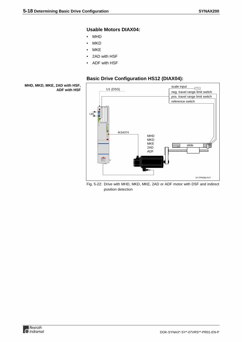
5-18 Determining Basic Drive Configuration SYNAX200
DOK-SYNAX*-SY*-07VRS**-PR01-EN-P
Usable Motors DIAX04:• MHD
• MKD
• MKE
• 2AD with HSF
• ADF with HSF
Basic Drive Configuration HS12 (DIAX04):
pos. travel range limit switchneg. travel range limit switch
scale inputU1 (DSS)
SY7PR096.FH7
MHDMKDMKE2ADADF
reference switch
slide
Read and followInstructions for Electrical Drives"manual,DOK-GENERL-DRIVE******-SVS...
DANGHigh oltage.Danger of electrical shock.Do not touch electrical connectionsfo5 minutes after switching
LWL
IKS4374
Fig. 5-22: Drive with MHD, MKD, MKE, 2AD or ADF motor with DSF and indirectposition detection
MHD, MKD, MKE, 2AD with HSF,ADF with HSF

SYNAX200 Determining Basic Drive Configuration 5-19
DOK-SYNAX*-SY*-07VRS**-PR01-EN-P
Drive with Direct Incremental Position Detection
• motor encoder with either singleturn or multiturn absolute encoder
• load position directly detected via incremental external encoder
• gear error statically compensated
Usable Motors DKR:• 2AD with HSF
• ADF with HSF
Basic Drive Configuration BE32 (DKR):
pos. travel range limit switch
neg. travel range limit switch
scale inputU1 (DSS)
SY7PR010.FH7
2ADADF
reference switch
slide
LWL
linear scale
U2 (DLF)
incrementallinear scale
withsine output
DIGITAL COMPACT CONTROLLER DKR 4
H1
X4
X2
U5
U2
S2
U4
U1 U3
X9
1
6
1
7
X8
H2
S1
X3X7
1
10
1
11
X3
Fig. 5-23: Drive with 2AD or ADFmotor with DSF with direct incremental positiondetection
Features:
2AD with HSF, ADF with HSF
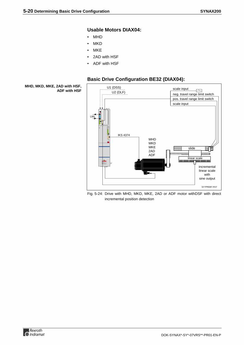
5-20 Determining Basic Drive Configuration SYNAX200
DOK-SYNAX*-SY*-07VRS**-PR01-EN-P
Usable Motors DIAX04:• MHD
• MKD
• MKE
• 2AD with HSF
• ADF with HSF
Basic Drive Configuration BE32 (DIAX04):
pos. travel range limit switchneg. travel range limit switch
scale inputU1 (DSS)
SY7PR097.FH7
MHDMKDMKE2ADADF
scale input
slide
Read and followInstructions for Electrical Drives"manual,DOK-GENERL-DRIVE******-SVS...
DANGHigh oltage.Danger of electrical shock.Do not touch electrical connectionsfo5 minutes after switching
LWL
incrementallinear scale
withsine output
U2 (DLF)
IKS 4374
linear scale
Fig. 5-24: Drive with MHD, MKD, MKE, 2AD or ADF motor withDSF with directincremental position detection
MHD, MKD, MKE, 2AD with HSF,ADF with HSF

SYNAX200 Determining Basic Drive Configuration 5-21
DOK-SYNAX*-SY*-07VRS**-PR01-EN-P
Drive with Direct Absolute Position Detection
• gearwheel encoder as motor encoder
• load position directly detected via absolute external encoder
• gear error statically compensated
Usable Motors DKR:• 2AD with gearwheel encoder
• 1MB with gearwheel encoder
Basic Drive Configuration BE45 (DKR):
pos. travel range limit switch
neg. travel range limit switch
scale input
U1 (DSS)
SY7PR011.FH7
1MBwith gearwheel encoder2ADwith gearwheel encoder
slide
LWL
U3 (DAG)
absolutelinear scalewith EnDat
or SSIinterface
U2 (DZF)
DIGITAL COMPACT CONTROLLER DKR 4
H1
X4
X2
U5
U2
S2
U4
U1 U3
X9
1
6
1
7
X8
H2
S1
X3X7
1
10
1
11
X3
linear scale
Fig. 5-25: Drive with 1MB or 2AD motor with gearwheel encoder with directabsolute position detection
Features:
1MB, 2AD:

5-22 Determining Basic Drive Configuration SYNAX200
DOK-SYNAX*-SY*-07VRS**-PR01-EN-P
Usable Motors DIAX04:• 2AD with gearwheel encoder
• 1MB with gearwheel encoder
Basic Drive Configuration HS45 (DIAX04):
pos. travel range limit switchneg. travel range limit switch
scale input
U1 (DSS)
SY7PR098.FH7
1MBwith gearwheel encoder2ADwith gearwheel encoder
slide
Read and followInstructions for Electrical Drives"manual,DOK-GENERL-DRIVE******-SVS...
DANGHigh oltage.Danger of electrical shock.Do not touch electrical connectionsfo5 minutes after switching
LWL
U2 (DLF)
absolutelinear scalewith EnDat
or SSIinterface
U3 (DAG)
linear scale
Fig. 5-26: Drive with 1MB or 2AD motor with gearwheel encoder with directabsolute position detection
1MB, 2AD:

SYNAX200 Determining Basic Drive Configuration 5-23
DOK-SYNAX*-SY*-07VRS**-PR01-EN-P
Drive with Linear Motor and Incremental Position Detection
• incremental position detection via external linear scale with sinusoidaloutput
• Direct Drive
• highest possible degree of static and dynamic precision
• high achievable acceleration of up to 100 m/s²
Usable Motors DKR:• LAF
• LAR
• LSF
Basic Drive Configuration BE32 (DKR):
pos. travel range limit switch
neg. travel range limit switch
scale input
reference switch
LWL
U2 (DLF)
U1 (DSS)
incrementallinear scale with
sine output
linear motorLARLAFLSF SY7PR012.FH7
DIGITAL COMPACT CONTROLLER DKR 4
H1
X4
X2
U5
U2
S2
U4
U1 U3
X9
1
6
1
7
X8
H2
S1
X3X7
1
10
1
11
X3
Fig. 5-27: Drive with linear motor LAR, LAF or LSF and incremental positiondetection
Features:
LAR, LAF, LSF:
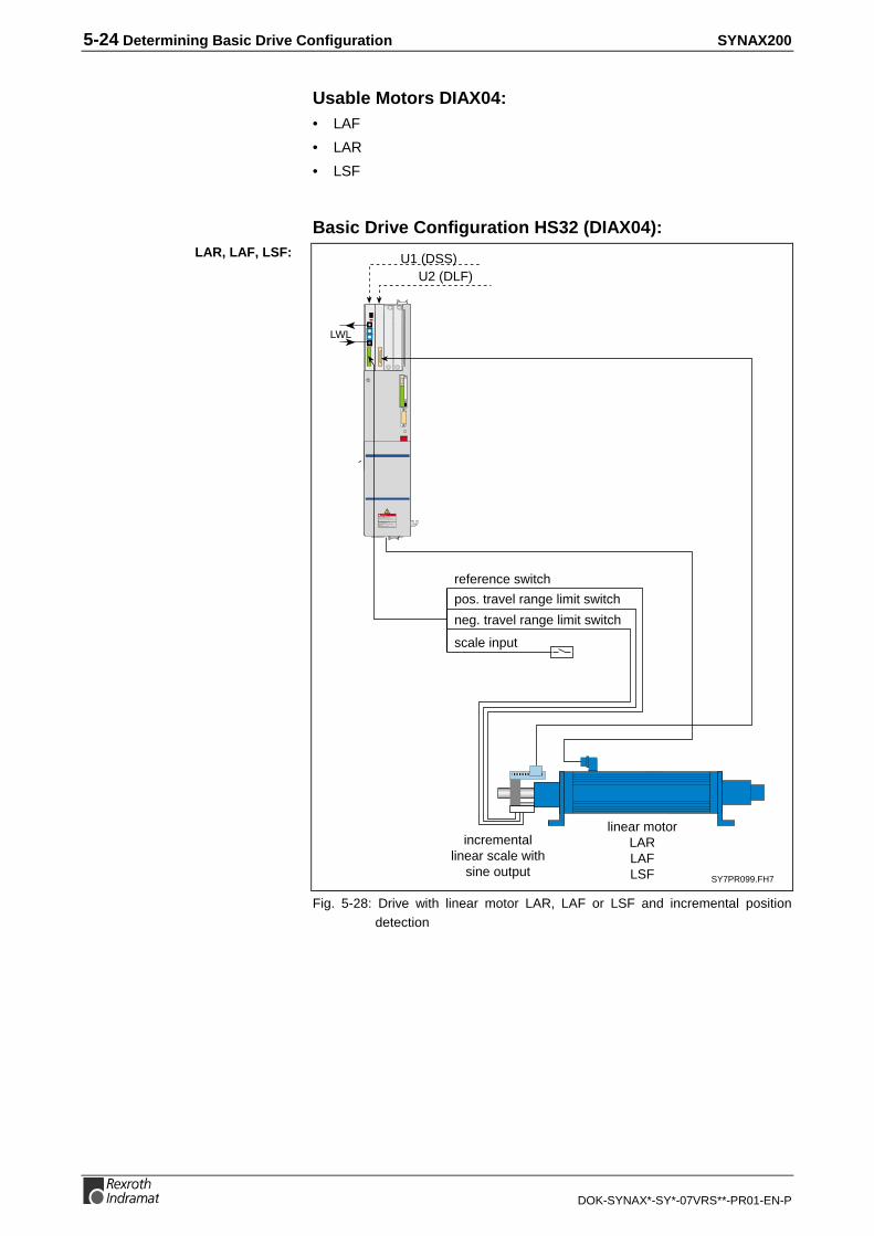
5-24 Determining Basic Drive Configuration SYNAX200
DOK-SYNAX*-SY*-07VRS**-PR01-EN-P
Usable Motors DIAX04:• LAF
• LAR
• LSF
Basic Drive Configuration HS32 (DIAX04):
pos. travel range limit switch
neg. travel range limit switch
scale input
reference switch
Read and followInstructions for Electrical Drives"manual,DOK-GENERL-DRIVE******-SVS...
DANGHigh oltage.Danger of electrical shock.Do not touch electrical connectionsfo5 minutes after switching
LWL
U2 (DLF)U1 (DSS)
incrementallinear scale with
sine output
linear motorLARLAFLSF SY7PR099.FH7
Fig. 5-28: Drive with linear motor LAR, LAF or LSF and incremental positiondetection
LAR, LAF, LSF:

SYNAX200 Determining Basic Drive Configuration 5-25
DOK-SYNAX*-SY*-07VRS**-PR01-EN-P
Drive with Linear Motor and Absolute Position Detection
• absolute position detection via external linear scale with EnDatinterface
• DirectDrive
• highest possible degree of static and dynamic precision
• high achievable acceleration of up to 100 m/s²
Usable Motors DKR:• LAF
• LAR
• LSF
Basic Drive Configuration BE45 (DKR):
pos. travel range limit switch
neg. travel range limit switch
scale input
reference switch
LWL
DIGITAL COMPACT CONTROLLER DKR 4
H1
X4
X2
U5
U2
S2
U4
U1 U3
X9
1
6
1
7
X8
H2
S1
X3X7
1
10
1
11
X3
U2 (DAG)
U1 (DSS)
linear scale withEnDat interface
linear motorLARLAFLSF SY7PR053.FH7
Fig. 5-29: Drive with linear motor LAR, LAF or LSF and absolute positiondetection
Features:
LAR, LAF, LSF:

5-26 Determining Basic Drive Configuration SYNAX200
DOK-SYNAX*-SY*-07VRS**-PR01-EN-P
Usable Motors DIAX04:• LAF
• LAR
• LSF
Basic Drive Configuration HS45 (DIAX04):
pos. travel range limit switch
neg. travel range limit switch
scale input
reference switch
Read and followInstructions for Electrical Drives"manual,DOK-GENERL-DRIVE******-SVS...
DANGHigh oltage.Danger of electrical shock.Do not touch electrical connectionsfo5 minutes after switching
LWL
U2 (DAG)U1 (DSS)
linear scale withEnDat interface
linear motorLARLAFLSF SY7PR100.FH7
Fig. 5-30: Drive with linear motor LAR, LAF or LSF and absolute positiondetection
LAR, LAF, LSF:

SYNAX200 Determining the Control-Related Plug-In Cards 6-1
DOK-SYNAX*-SY*-07VRS**-PR01-EN-P
6 Determining the Control-Related Plug-In Cards
6.1 Determining Parallel I/Os
DEA04 or DEA08 parallel I/O cards can be inserted into DKR and HDScontrollers.
Binary signals can be exchanged with this card between the PPC and aPLC. The voltage level equals 24 volts. The inputs and outputs are opto-decoupled.
Fifteen inputs (the 16th input monitors the 24 V power source) and 16outputs are available. The 16th input can be used as a watchdog or aregular output.
32 inputs, 24 outputs and a watchdog ouput are available.
The signals applied to this I/O are transmitted via the SERCOS fibre-optics cable link to the PPC.
SY6PR016.FH7
15 inputs
16 outputs
DEA04
parallel I/O
in the slot of
a DKR/HDS
24V
Fig. 6-1: Parallel I/O card DEA04
SY6PR056.FH7
32 inputs
24 outputs
DEA 08
parallel I/O
in the slot of
a DKR/HDS
24V
Fig. 6-2: Parallel I/O card DEA08
DEA04
DEA08

6-2 Determining the Control-Related Plug-In Cards SYNAX200
DOK-SYNAX*-SY*-07VRS**-PR01-EN-P
6.2 Combination Options of the External I/O (Drive Internal)
In addition to the RECO I/O modules the following I/O variants areavailable drive internal:
• drive plug-in card DEA04
• drive plug-in card DEA08
These can be used for the following functions:
• I/O logic (VKL)
• High-speed cam switch group (HS cams)
The drive plug-in cards can also be used to output the binary value of aparameter or to read it in.
Note: For parameter output or reading one in, it is also possible touse the drive plug-in cards DEA05/DEA06 or DEA09/DEA10.
DEA04 DEA08
Example A inputs VKL,outputs 16 HS cams(32 HS cams with 2 * DEA04)
inputs VKL,outputs VKL
Example B inputs VKL,outputs VKL
inpputs VKL,outputs 24 HS cams
Example C inputs VKL,parameter output
inputs VKL,outputs VKL
Example D parameter input,outputs VKL
inputs VKL,parameter output
Fig. 6-3: Example configuration
The following combinations are not possible:
• High-speed cams configured on a DEA card while simultaneouslyusing the outputs of this card in the I/O logic or for parameter output.
• Parameter output via P-0-0124 (e.g., drive cams P-0-0135) on aDEA04 or DEA08 activated and the outputs used in the VKL or for HScams.
• Parameter read in via P-0-0125 activated by DEA04 or DEA08 and theinputs used in the VKL.

SYNAX200 Determining the Control-Related Plug-In Cards 6-3
DOK-SYNAX*-SY*-07VRS**-PR01-EN-P
6.3 Determining the Master Axis
If it is necessary that the slave drive of the electronic gears has referenceto a real master axis, then a master axis encoder must be mounted to thismaster axis.
Note: The master axis encoder must be mounted so that one masteraxis revolution equals one machine cycle (1 product ejection).This can be reached when parametrize a electronic measuringgear if necessary (see DOK-SYNAX*-SY*-07VRS**-FK01-EN-P, section 2.2 Real master axis - electronic measuring gear)
The master axis encoder is mounted to an encoder interface in the driveamplifier. The master axis position is generated from the encoder signalsand transmitted via SERCOS interface to the PPC motion control.
High-Resolution Singleturn Encoder GDS or MultiturnEncoder GDM Made by IndramatThe singleturn encoder GDS or the multiturn encoder GDM is connectedvia encoder interface DFF or DSF interface (connector X4) to a driveamplifier.
The singleturn encoder GDS delivers an absolute encoder informationwithin one revolution, the multiturn encoder within 4096 revolutions.
SY7PR017.FH7
master axis encoderGDS 1.1/GDM1.1
DFF
master axis position
in the slot of a
DKR/HDS
Fig. 6-4: GDS or GDM master axis encoder with encoder interface DFF
SY7PR018.FH7Read and followInstructions for Electrical Drives"manual,DOK-GENERL-DRIVE******-SVS...
DANGHigh oltage.Danger of electrical shock.Do not touch electrical connectionsfo5 minutes after switching
master axis encoderGDS 1.1/GDM 1.1
X4
Fig. 6-5: GDS or GDM master axis encoder with DSF interface X4 (DIAX04)
DIAX03, DIAX04

6-4 Determining the Control-Related Plug-In Cards SYNAX200
DOK-SYNAX*-SY*-07VRS**-PR01-EN-P
EnDat/SSI EncoderIt is also possible to connect a real master axis using an EnDat/SSIencoder.
In this case use encoder interface DAG.
SY7PR034.FH7
EnDat/SSI encoder
DAG
master axis position
in the slot of a
DKR/HDS
Fig. 6-6: EnDat and SSI encoder interface DAG
The EnDat encoder is connected to the second interface X8. SSIencoders are not supported.
Barc
ode
0 1
23
456
78
90 1
23
456
78
9
H1
S1
S3 S2
Barc
ode
Type
nsch
ild
12
34
56
78
91
23
4
111213141516
17185
67
8
12
34
56
78
XE2
XE1
L+
L-
L1
L2
L3
A1
A2
A3
Read and followInstructions for Electrical Drives"manual,DOK-GENERL-DRIVE******-SVS...
DANGHigh oltage.Danger of electrical shock.Do not touch electrical connectionsfor5 minutes after switching
777
EnDat
Fig. 6-7: EnDat encoder interface DKC
Note: Use only encoders with binary line numbers (2n).Recommended type: encoder with 2048 number of lines.
DIAX03, DIAX04
ECODRIVE03

SYNAX200 Determining the Control-Related Plug-In Cards 6-5
DOK-SYNAX*-SY*-07VRS**-PR01-EN-P
Incremental Encoder with Sinusoidal Signals 1VssIt is also possible to connect a real master axis using an incrementalencoder with sinousoidal signals 1Vss.
Note: Use only encoders with binary line numbers (2n).
In this case use encoder interface DLF.
SY7PR112.FH7
incremental encoder withsinusoidal signals 1Vss
DLF
master axis position
in the slot of a
DKR/HDS
Fig. 6-8: Incremental encoder with sinousoidal signals 1Vss
Note: There is no zero impulse evaluation, that means that themaster axis position has no absolute reference
The incremental encoder with sinousoidal signals 1Vss is connected tothe second interface X8.
Barc
ode
0 1
23
456
78
90 1
23
456
78
9
H1
S1
S3 S2
Barc
ode
Type
nsch
ild
12
34
56
78
91
23
4
111213141516
17185
67
8
12
34
56
78
XE2
XE1
L+
L-
L1
L2
L3
A1
A2
A3
Read and followInstructions for Electrical Drives"manual,DOK-GENERL-DRIVE******-SVS...
DANGHigh oltage.Danger of electrical shock.Do not touch electrical connectionsfor5 minutes after switching
8
incremental encoder withsinusoidal signals 1Vss
Fig. 6-9: incremental encoder with sinousoidal signals 1Vss
Note: The evaluation of the zero impulse of ECODRIVE03 isparameterizable. If the zero impulse is evaluated, the masteraxis position changes immediately when registrating the zeroimpulse. This must be considered for application.
DIAX03, DIAX04
ECODRIVE03

6-6 Determining the Control-Related Plug-In Cards SYNAX200
DOK-SYNAX*-SY*-07VRS**-PR01-EN-P
6.4 Determining Analog Inputs
Two analog signals per drive can be detected via the analog interfaceDAE.
Analog signals are read by the drive and transmitted via the SERCOSLWL ring to the PPC. The PPC processes and allocates the analogsignals (e.g., actual values of the tension control).
SY7PR019.FH7
analog signal 1analog signal 2
DAE
in the slot of a
DKR/HDS
Fig. 6-10: Analog interface DAE
6.5 Master Axis Position Output
SSI EmulationThe master axis position in SSI format can be generated via the SSIoutput interface DSA.
The DSA card can be placed in any drive in the fibre-optics ring for thispurpose.
SY7PR020.FH7
SSI
DSA
in the slot of a
DKR/HDS
Fig. 6-11: Master axis position - SSI output interface DSA
The master axis position in SSI format can be generated via the SSIoutput interface X9 in any drive in the fibre-optics ring.
DKC**.3-040-7-FW, up side
XS
3
X9:incremental encoder/SSI emulation SY6PR069.FH7
Fig. 6-12: Master axis position - SSI output interface on ECODRIVE03
DIAX03, DIAX04
ECODRIVE03

SYNAX200 Determining the Control-Related Plug-In Cards 6-7
DOK-SYNAX*-SY*-07VRS**-PR01-EN-P
Incremental Encoder EmulationThe master axis position can be generated as an incremental signal viathe incremental encoder emulation interface DAE.
The DAE card can be placed in any drive in the fibre-optics ring for thispurpose.
SY7PR067.FH7
incremental encoderemulation
DAE
in the slot of a
DKR/HDS
Fig. 6-13: Incremental encoder emulation DAE
The master axis position can be generated as an incremental signal viathe incremental encoder emulation interface X9 in any drive in the fibre-optics ring.
See Fig. 6-12: Master axis position - SSI output interface on
DIAX03, DIAX04
ECODRIVE03

6-8 Determining the Control-Related Plug-In Cards SYNAX200
DOK-SYNAX*-SY*-07VRS**-PR01-EN-P
6.6 Encoder Branching DGA 01.2 for Encoders withSinusoidal Voltage Signals 1Vss
General
X6 X5
X3 X4
X1 X2
Read and followInstructions for Electrical Drives"manual,DOK-GENERL-DRIVE******-SVS...
DANGHigh oltage.Danger of electrical shock.Do not touch electrical connectionsfo5 minutes after switching
LWL
U1 (DSS)
U2 (DLF)
IKS4383
SY7PR107.FH7
externalincremental encoder
with sine outpute.g., Heidenhain
ROD 481ERN 180ERN 680RON 285
e.g., externalregister control
Fig. 6-14: Encoder branching DGA 01.2 example
The DGA makes it possible to distribute the signals of a measuringsystem to up to four measuring system inputs of different drivecontrollers. Possible applications of the DGA are:
• Parallel connection of linear motors using a measuring system
• Diverting position signals to external controls for the purpose ofmonitoring or as master axis positions
All measuring systems with sinusoidal output signals and a signal level of1 V
SS can be used (Heidenhain voltage interface).
The DGA makes it possible to connect up to four drive controllers. Thereis also an output with square-wave signals.
Sv5115f1.fh7
1VSS
DGA01.2
Measuring system:Linear scale orrotary encoder
Ext. control or meas.signal evaluation
DLF01.1
DLF01.1
DLF01.1
DLF01.1
X1
X2
X3
X4
X5
X6
1)
1) Terminal X2 supplies voltage for the DGA and must always be present.
Fig. 6-15: Connection schematics - DGA01.2
Connection Ready-made cable
from DGA01.2 (X2, X3, X4, X5) to DLF01.1 IKS0131
from DGA01.2 (X6) to DEF01.1 IKS0331
Fig. 6-16: Ready-made cable
Connection schematics DGA01.2
Ready-made cable

SYNAX200 Determining the Control-Related Plug-In Cards 6-9
DOK-SYNAX*-SY*-07VRS**-PR01-EN-P
Terminal Diagram
Ap5242f1.fh7
DGA01.2
1 2 5 6 7 8
0V +8V
4 3 9
max. cable length: 75 m
INS0701
X2 A+ A- B+ B- R+ R-
7 8 6 5 4 3
0V +8V
10 2 1 12
A+ A- B+ B- R+ R-
A+
A-
B+
B-
R+
R-
0V
frei
DLF
INS0701
1
2
5
6
7
8
4
3
9
X4
A+
A-
B+
B-
R+
R-
0V
frei
DLF
INS0701
1
2
5
6
7
8
4
3
9
X5
3
4
5
6
8
1
10
12
9
Ua0
Ua0
Ua1
Ua1
Ua2
Ua2
INS0493
0V
frei incr
emen
tal e
ncod
er o
utpu
t
X6
A+
A-
B+
B-
R+
R-
0V
frei
INS0701
1
2
5
6
7
8
4
3
9
X3
to D
LF p
ositi
on in
terf
ace
Terminal X2 supplies theDGA with power and mustalways be there.
DLF
max. processing frequencyfmax = 400 kHz
measuring sytem, e.g.,LIF181, LS186, LS468from Heidenhain
5 6 8 1 3 4 10 12 9
INS0488
X1
1VSS
max. cable length: 30 m
0V +5VA+ A- B+ B- R+ R-
Fig. 6-17: Terminal diagram DGA01.2

6-10 Determining the Control-Related Plug-In Cards SYNAX200
DOK-SYNAX*-SY*-07VRS**-PR01-EN-P
Technical Data
External Measuring SystemOutput voltage X1/12: DC +5 V (±5%)
max. output load X1/12: 150 mA
Approximately sinusoidal signals
Signal voltage: A, B, R 1 VSS
max. frequency for measuring system signals: A, B 400 kHz
max. frequency for reference signal: R 15 kHz
X1
voltage signal: A+, B+, R+
voltage signal: A-, B-, R-
(458662
DGA01.2
5, 8, 3
6, 1, 4
-
+
121 RX1
Fig. 6-18: Signal input circuit
Sv5116f1.fh7
Signal period360° el.
90° el.
0
0
0
A
B
R
Fig. 6-19: Block diagram of the signal paths
Supply voltage for externalmeasuring system
Signal form
Voltage signals
Signal-input circuit
Block diagram of the signalpaths

SYNAX200 Determining the Control-Related Plug-In Cards 6-11
DOK-SYNAX*-SY*-07VRS**-PR01-EN-P
Diverting Measuring System Signals to Four ConnectionThe signals from the measuring system are diverted to connections X2,X3, X4 and X5.
The DGA01.2 receives ist power via terminal X2.
Connecting voltage X2/3: DC +8 V (±5%)
Maximum current consumption: 300 mA
see Fig. 6-18: Signal input circuit
Outputting Measuring System Signals as Square-WaveSignalsSinusoidal signals of the measuring system are generated via terminal X6as square-wave incremental signals.
t2
t1
Ua1
Ua0
Ua2
Sv5117f1.fh7Encoder shaft turning clockwise
t1
Fig. 6-20: Voltage level and phase position of incremental signals
Designation Unit min. type /value
max.
Phase position Ua1 degree 0
Phase position Ua2 degree 90
Signal amplitude
Ua-(/Ua)
VSS 7
Reference point delay t1 ns 50
Edge distance t2 ns 500
Fig. 6-21: Incremental signal data
DGA01.2 supply
Recommended signal inputcircuit

6-12 Determining the Control-Related Plug-In Cards SYNAX200
DOK-SYNAX*-SY*-07VRS**-PR01-EN-P
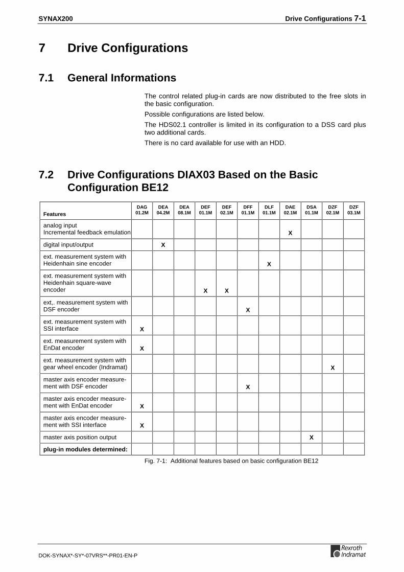
SYNAX200 Drive Configurations 7-1
DOK-SYNAX*-SY*-07VRS**-PR01-EN-P
7 Drive Configurations
7.1 General Informations
The control related plug-in cards are now distributed to the free slots inthe basic configuration.
Possible configurations are listed below.
The HDS02.1 controller is limited in its configuration to a DSS card plustwo additional cards.
There is no card available for use with an HDD.
7.2 Drive Configurations DIAX03 Based on the BasicConfiguration BE12
FeaturesDAG01.2M
DEA04.2M
DEA08.1M
DEF01.1M
DEF02.1M
DFF01.1M
DLF01.1M
DAE02.1M
DSA01.1M
DZF02.1M
DZF03.1M
analog inputIncremental feedback emulation X
digital input/output X
ext. measurement system withHeidenhain sine encoder X
ext. measurement system withHeidenhain square-waveencoder X X
ext,. measurement system withDSF encoder X
ext. measurement system withSSI interface X
ext. measurement system withEnDat encoder X
ext. measurement system withgear wheel encoder (Indramat) X
master axis encoder measure-ment with DSF encoder X
master axis encoder measure-ment with EnDat encoder X
master axis encoder measure-ment with SSI interface X
master axis position output X
plug-in modules determined:
Fig. 7-1: Additional features based on basic configuration BE12

7-2 Drive Configurations SYNAX200
DOK-SYNAX*-SY*-07VRS**-PR01-EN-P
Configurationdesignation:
DAG01.2M
DEA04.2M
DEA08.1M
DEF01.1M
DEF02.1M
DFF01.1M
DLF01.1M
DAE02.1M
DSA01.1M
DZF02.1M
DZF03.1M
BE09-01-FW X
BE10-01-FW X X
BE12-01-FW
BE23-01-FW X
BE25-01-FW X X X
BE30-01-FW X X
BE47-01-FW X X
BE54-01-FW X
BE56-01-FW X
BE59-01-FW X X
BE60-01-FW X X
BE73-01-FW X X X
BE76-01-FW X
BE78-00-FW X X
BE79-01-FW X
BE80-01-FW X X
BE84-01-FW X X
BE86-01-FW X X X
BE91-01-FW X X
BE92-01-FW X X
BE94-01-FW X X X
BE99-01-FW X X X
BT08-01-FW X X X
BT10-01-FW X X X
BT13-01-FW X X X
BT15-01-FW X X X
BT20-01-FW X
BT52-01-FW X X
BT53-01-FW X X
BT56-01-FW X X
BT67-01-FW X X
BT68-01-FW X X X
BT69-01-FW X X X
Fig. 7-2: Drive configurations based on basic configuration BE12
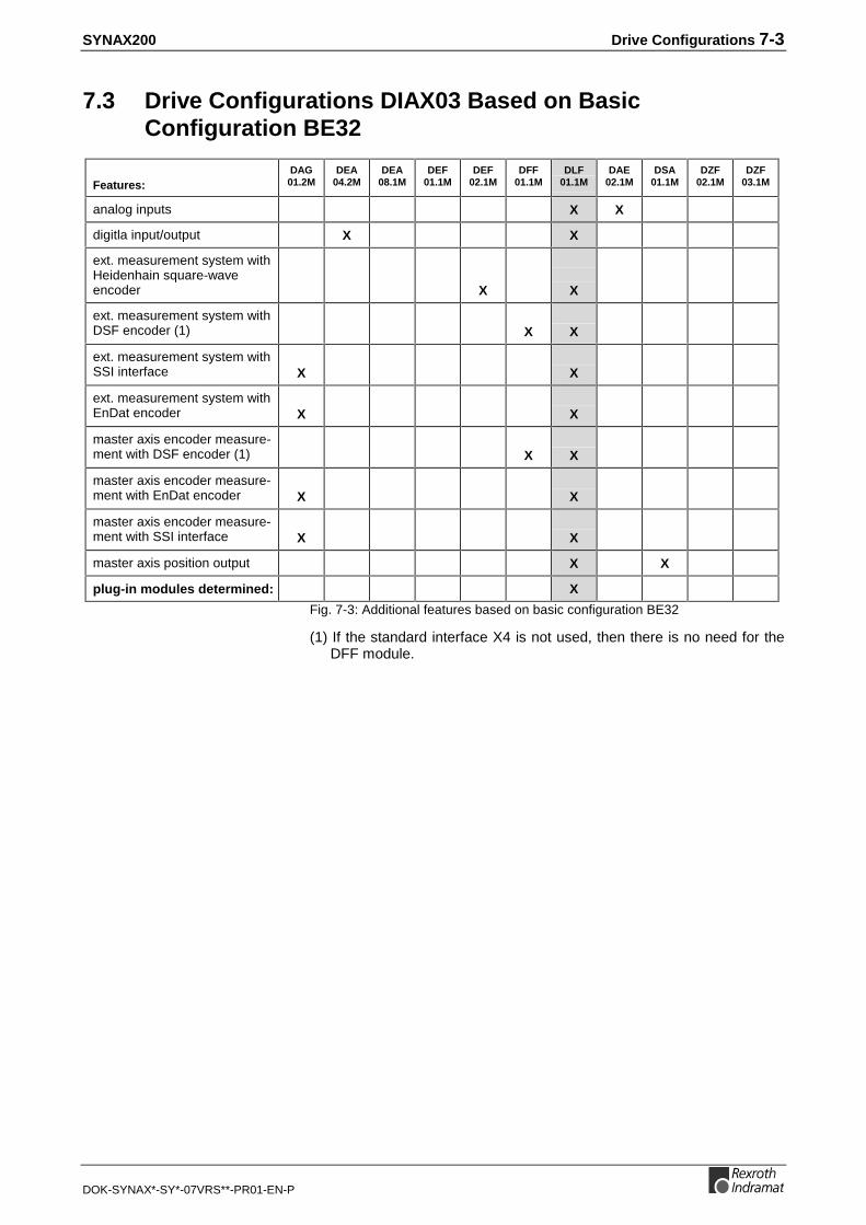
SYNAX200 Drive Configurations 7-3
DOK-SYNAX*-SY*-07VRS**-PR01-EN-P
7.3 Drive Configurations DIAX03 Based on BasicConfiguration BE32
Features:DAG01.2M
DEA04.2M
DEA08.1M
DEF01.1M
DEF02.1M
DFF01.1M
DLF01.1M
DAE02.1M
DSA01.1M
DZF02.1M
DZF03.1M
analog inputs X X
digitla input/output X X
ext. measurement system withHeidenhain square-waveencoder X X
ext. measurement system withDSF encoder (1) X X
ext. measurement system withSSI interface X X
ext. measurement system withEnDat encoder X X
master axis encoder measure-ment with DSF encoder (1) X X
master axis encoder measure-ment with EnDat encoder X X
master axis encoder measure-ment with SSI interface X X
master axis position output X X
plug-in modules determined: X
Fig. 7-3: Additional features based on basic configuration BE32
(1) If the standard interface X4 is not used, then there is no need for theDFF module.

7-4 Drive Configurations SYNAX200
DOK-SYNAX*-SY*-07VRS**-PR01-EN-P
Configurationdesignation:
DAG01.2M
DEA04.2M
DEA08.1M
DEF01.1M
DEF02.1M
DFF01.1M
DLF01.1M
DAE02.1M
DSA01.1M
DZF02.1M
DZF03.1M
BE08-01-FW X X
BE28-01-FW X X X
BE32-01-FW X
BE33-01-FW X X
BE55-01-FW X X X
BE57-01-FW X X X
BE58-01-FW X X
BE62-01-FW X X
BE68-01-FW X X X
BT01-01-FW X X
BT02-01-FW X X X
BT03-01-FW X X X
BT04-01-FW X X
BT05-01-FW X X X
BT06-01-FW X X X
BT07-01-FW X X X
BT54-01-FW X X
BT57-01-FW X X X
BT58-01-FW X X X
BT66-01-FW X X X
Fig. 7-4: Drive configuration based on basic configuration BE32

SYNAX200 Drive Configurations 7-5
DOK-SYNAX*-SY*-07VRS**-PR01-EN-P
7.4 Drive Configuration DIAX03 Based on BasicConfiguration BE37
Features:DAG01.2M
DEA04.2M
DEA08.1M
DEF01.1M
DEF02.1M
DFF01.1M
DLF01.1M
DAE02.1M
DSA01.1M
DZF02.1M
DZF03.1M
analog input X X
didgital input/output X X
ext. measurement system withHeidenhain square-waveencoder X X
ext. measurement system withDSF encoder (1) X X
ext. measurement system withSSI interface X X
ext. measurement system withEnDat encoder X X
master axis encoder measure-ment with DSF-Geber (1) X X
master axis encoder measure-ment with EnDat encoder X X
master axis encoder measure-ment with SSI interface X X
master axis position output X X
plug-in modules determined: X
Fig. 7-5: Additional features based on basic configuration BE37
(1) If the standard interface X4 is not used, then there is no need for theDFF02.1M module.

7-6 Drive Configurations SYNAX200
DOK-SYNAX*-SY*-07VRS**-PR01-EN-P
Configurationdesignation:
DAG01.2M
DEA04.2M
DEA08.1M
DEF01.1M
DEF02.1M
DFF01.1M
DLF01.1M
DAE02.1M
DSA01.1M
DZF02.1M
DZF03.1M
BE02-02-FW X X X
BE03-02-FW X X X
BE04-02-FW X X
BE19-01-FW X X
BE22-01-FW X X X
BE26-01-FW X X
BE27-01-FW X X
BE32-01-FW X X X
BE37-01-FW X
BE38-01-FW X X
BE63-01-FW X X X
BE65-01-FW X X X
BE67-01-FW X X X
BE70-01-FW X X
BE72-02-FW X X X
BE88-01-FW X X X
BE89-01-FW X X X
BE90-01-FW X X X
BT55-01-FW X X
BT59-01-FW X X
BT60-01-FW X X
BT61-01-FW X X X
BT62-01-FW X X X
BT63-01-FW X X X
Fig. 7-6: Drive configuration based on basic configuration BE37

SYNAX200 Drive Configurations 7-7
DOK-SYNAX*-SY*-07VRS**-PR01-EN-P
7.5 Drive Configuration DIAX03 Based on BasicConfiguration BE45
FeaturesDAG01.2M
DEA04.2M
DEA08.1M
DEF01.1M
DEF02.1M
DFF01.1M
DLF01.1M
DAE02.1M
DSA01.1M
DZF02.1M
DZF03.1M
analog inputs X X
digital input/output X X
ext. measurement system withHeidenhain sine encoder X X
ext. measurement system withHeidenhain square-waveencoder X X X
ext. measurement system withDSF encoder (1) X X
ext. measurement system withgear wheel encoder (Indramat) X X
master axis encoder measure-ment with DSF encoder (1) X X
master axis position output X X
plug-in modules determined: X
Fig. 7-7: Additional features based on basic configuration BE45
(1) If the standard interface X4 is not used, then there is no need for theDFF module.

7-8 Drive Configurations SYNAX200
DOK-SYNAX*-SY*-07VRS**-PR01-EN-P
Configurationdesignation:
DAG01.2M
DEA04.2M
DEA08.1M
DEF01.1M
DEF02.1M
DFF01.1M
DLF01.1M
DAE02.1M
DSA01.1M
DZF02.1M
DZF03.1M
BE02-02-FW X X X
BE03-02-FW X X X
BE04-02-FW X X
BE45-01-FW X
BE66-01-FW X X
BE72-02-FW X X X
BE74-02-FW X X
BE83-00-FW X X X
BE87-01-FW X X X
BE90-01-FW X X X
BE93-01-FW X X
BT01-01-FW X X
BT02-01-FW X X X
BT03-01-FW X X X
BT09-01-FW X X X
BT11-01-FW X X X
BT12-01-FW X X X
BT14-01-FW X X X
BT18-01-FW X X
BT24-01-FW X X
BT51-01-FW X X
BT58-01-FW X X X
BT63-01-FW X X X
BT64-01-FW X X X
BT65-01-FW X X X
Fig. 7-8: Drive configuration based on basic configuration BE45

SYNAX200 Drive Configurations 7-9
DOK-SYNAX*-SY*-07VRS**-PR01-EN-P
7.6 Drive Configuration DIAX04 Based on BasicConfiguration HS12
FeaturesDAG01.2M
DEA04.2M
DEA08.1M
DEF01.1M
DEF02.1M
DFF01.1M
DLF01.1M
DAE02.1M
DSA01.1M
DZF02.1M
DZF03.1M
analog inputincremental feedbackemulation X
digital input/output X
ext. measurement system withHeidenhain sine encoder X
ext. measurement system withHeidenhain square-waveencoder X X
ext. measurement system withDSF encoder X
ext. measurement system withSSI interface X
ext. measurement system withEnDat encoder X
ext. measurement system withgear wheel encoder (Indramat) X
master axis encoder measure-ment with DSF encoder X
master axis encoder measure-ment with EnDat encoder X
master axis encoder measure-ment with SSI interface X
master axis position output X
plug-in modules determined:
Fig. 7-9: Additional features based on basic configuration HS12

7-10 Drive Configurations SYNAX200
DOK-SYNAX*-SY*-07VRS**-PR01-EN-P
Configurationdesignation:
DAG01.2M
DEA04.2M
DEA08.1M
DEF01.1M
DEF02.1M
DFF01.1M
DLF01.1M
DAE02.1M
DSA01.1M
DZF02.1M
DZF03.1M
HS09-01-FW X
HS10-01-FW X X
HS12-01-FW
HS23-01-FW X
HS25-01-FW X X X
HS30-01-FW X X
HS47-01-FW X X
HS54-01-FW X
HS56-01-FW X
HS59-01-FW X X
HS60-01-FW X X
HS73-01-FW X X X
HS76-01-FW X
HS78-01-FW X X
HS79-01-FW X
HS80-01-FW X X
HS84-01-FW X X
HS86-01-FW X X X
HS91-01-FW X X
HS92-01-FW X X
HS94-01-FW X X X
HS99-01-FW X X X
HT08-01-FW X X X
HT10-01-FW X X X
HT13-01-FW X X X
HT15-01-FW X X X
HT20-01-FW X
HT31-01-FW X X
HT32-01-FW X X
HT35-01-FW X X
HT46-01-FW X X
HT47-01-FW X X X
HT48-01-FW X X X
Fig. 7-10: Drive configuration based on basic configuration HS12

SYNAX200 Drive Configurations 7-11
DOK-SYNAX*-SY*-07VRS**-PR01-EN-P
7.7 Drive Configuration DIAX04 Based on BasicConfiguration HS32
Features:DAG01.2M
DEA04.2M
DEA08.1M
DEF01.1M
DEF02.1M
DFF01.1M
DLF01.1M
DAE02.1M
DSA01.1M
DZF02.1M
DZF03.1M
analog input X X
digital input/output X X
ext. measurement system withHeidenhain square-waveencoder
X X
ext. measurement system withDSF encoder (1) X X
ext. measurement system withSSI interface X X
ext. measurement system withEnDat encoder X X
master axis encoder measure-ment with DSF encoder (1) X X
master axis encoder measure-ment with EnDat encoder X X
master axis encoder measure-ment with SSI interface X X
master axis position output X X
plug-in modules determined: X
Fig. 7-11: Additional features based on basic configuration HS32
(1) If the standard interface X4 is not used, then there is no need for theDFF module.

7-12 Drive Configurations SYNAX200
DOK-SYNAX*-SY*-07VRS**-PR01-EN-P
Configurationdesignation:
DAG01.2M
DEA04.2M
DEA08.1M
DEF01.1M
DEF02.1M
DFF01.1M
DLF01.1M
DAE02.1M
DSA01.1M
DZF02.1M
DZF03.1M
HS08-01-FW X X
HS28-01-FW X X X
HS32-01-FW X
HS33-01-FW X X
HS55-01-FW X X X
HS57-01-FW X X X
HS58-01-FW X X
HS62-01-FW X X
HS68-01-FW X X X
HT01-01-FW X X
HT02-01-FW X X X
HT03-01-FW X X X
HT04-01-FW X X
HT05-01-FW X X X
HT06-01-FW X X X
HT07-01-FW X X X
HT33-01-FW X X
HT36-01-FW X X X
HT37-01-FW X X X
HT45-01-FW X X X
Fig. 7-12: Drive configuration based on basic configuration HS32

SYNAX200 Drive Configurations 7-13
DOK-SYNAX*-SY*-07VRS**-PR01-EN-P
7.8 Drive Configuration DIAX04 Based on BasicConfiguration HS37
Features:DAG01.2M
DEA04.2M
DEA08.1M
DEF01.1M
DEF02.1M
DFF01.1M
DLF01.1M
DAE02.1M
DSA01.1M
DZF02.1M
DZF03.1M
analog input X X
digital input/output X X
ext. measurement system withHeidenhain square-waveencoder X X
ext. measurement system withDSF encoder (1) X X
ext. measurement system withSSI interface X X
ext. measurement system withEnDat encoder X X
master axis encoder measure-ment with DSF-Geber (1) X X
master axis encoder measure-ment with EnDat encoder X X
master axis encoder measure-ment with SSI interface X X
master axis position output X X
plug-in modules determined: X
Fig. 7-13: Additional features based on basic configuration HS37
(1) If the standard interface X4 is not used, then there is no need for theDFF02.1M module.

7-14 Drive Configurations SYNAX200
DOK-SYNAX*-SY*-07VRS**-PR01-EN-P
Configurationdesignation:
DAG01.2M
DEA04.2M
DEA08.1M
DEF01.1M
DEF02.1M
DFF01.1M
DLF01.1M
DAE02.1M
DSA01.1M
DZF02.1M
DZF03.1M
HS02-02-FW X X X
HS03-02-FW X X X
HS04-02-FW X X
HS19-01-FW X X
HS22-01-FW X X X
HS26-01-FW X X
HS27-01-FW X X
HS36-01-FW X X X
HS37-01-FW X
HS38-01-FW X X
HS63-01-FW X X X
HS65-01-FW X X X
HS67-01-FW X X X
HS70-01-FW X X
HS72-02-FW X X X
HS88-01-FW X X X
HS89-01-FW X X X
HS90-01-FW X X X
HT34-01-FW X X
HT38-01-FW X X
HT39-01-FW X X X
HT40-01-FW X X X
HT41-01-FW X X X
Fig. 7-14: Drive configuration based on basic configuration HS37

SYNAX200 Drive Configurations 7-15
DOK-SYNAX*-SY*-07VRS**-PR01-EN-P
7.9 Drive Configuration DIAX04 Based on BasicConfiguration HS45
FeaturesDAG01.2M
DEA04.2M
DEA08.1M
DEF01.1M
DEF02.1M
DFF01.1M
DLF01.1M
DAE02.1M
DSA01.1M
DZF02.1M
DZF03.1M
analog input X X
digital input/output X X
ext. measurement system withHeidenhain sine encoder X X
ext. measurement system withHeidenhain square-waveencoder X X X
ext. measurement system withDSF encoder (1) X X
ext. measurement system withgear wheel encoder (Indramat) X X
master axis encoder measure-ment with DSF encoder (1) X X
master axis position output X X
plug-in modules determined: X
Fig. 7-15: Additional features based on basic configuration HS45
(1) If the standard interface X4 is not used, then there is no need for theDFF module.

7-16 Drive Configurations SYNAX200
DOK-SYNAX*-SY*-07VRS**-PR01-EN-P
Configurationdesignation:
DAG01.2M
DEA04.2M
DEA08.1M
DEF01.1M
DEF02.1M
DFF01.1M
DLF01.1M
DAE02.1M
DSA01.1M
DZF02.1M
DZF03.1M
HS02-02-FW X X X
HS03-02-FW X X X
HS04-02-FW X X
HS45-01-FW X
HS66-01-FW X X
HS72-02-FW X X X
HS72-02-FW X X X
HS74-02-FW X X
HS74-02-FW X X
HS81-01-FW X X
HS87-01-FW X X X
HS90-01-FW X X X
HS93-01-FW X X
HT01-01-FW X X
HT02-01-FW X X X
HT03-01-FW X X X
HT09-01-FW X X X
HT11-01-FW X X X
HT12-01-FW X X X
HT14-01-FW X X X
HT18-01-FW X X
HT24-01-FW X X
HT30-01-FW X X
HT37-01-FW X X X
HT41-01-FW X X X
HT42-01-FW X X X
HT44-01-FW X X X
HT72-01-FW X X
Fig. 7-16: Drive configuration based on basic configuration HS45

SYNAX200 Drive Configurations 7-17
DOK-SYNAX*-SY*-07VRS**-PR01-EN-P
7.10 Example
The rotary press and folding machine of the plant shown in Fig. 7-17should be equipped with the SYNAX200 system.
SY6FB002.FH7
rotarydie-cut folder
phase encoder
feederprintingunit 2
printingunit 1
Read and followInstructions for Electrical Drives"manual,DOK-GENERL-DRIVE******-SVS...
DANGHigh oltage.Danger of electrical shock.Do not touch electrical connectionsfor5 minutes after switching
Read and followInstructions for Electrical Drives"manual,DOK-GENERL-DRIVE******-SVS...
DANGHigh oltage.Danger of electrical shock.Do not touch electrical connectionsfor5 minutes after switching
Read and followInstructions for Electrical Drives"manual,DOK-GENERL-DRIVE******-SVS...
DANGHigh oltage.Danger of electrical shock.Do not touch electrical connectionsfor5 minutes after switching
Fig. 7-17: Printing machine partially equipped with individual drives
Motion Control ConfigurationThe PPC-R is used as a motion control with 3 slots. One slot of the PPC-R is assigned with the ARCNET and the PPC link assembly (DAQ)
An input module RME with 16 inputs and an output module RMA with 16outputs are used for I/O.
A mounting rack with 4 slots is used for taking up the motion control andthe I/O modules.
How to Order the Motion Control ConfigurationPos. 1 motion control PPC-R02.2N-P1N-Q1-NN-NN-FW
Pos. 1.1 relevant firmware FWA-PPCR0*-SY*-07VRS-MS
Pos. 2 input module RME02.2-16-DC024
Pos. 3 output module RMA02.2-16-DC024-200
Pos. 4 mounting rack RMB02.2-04

7-18 Drive Configurations SYNAX200
DOK-SYNAX*-SY*-07VRS**-PR01-EN-P
Drive ConfigurationThe following equipment is needed for all three drives and is alwaysbased on both precision and power requirements:
Axis Drive controller Motor
rotary die-cut HDS03.2-W075 MHD
anvil zylinder HDS03.2-W075 MHD
folding drive HDS04.2-W200 2AD
Fig. 7-18: Drive equipment
The result is the basic drive configuration HS12-01 on section 7.6. Theselection of the control-related plug-in modules follows the guidelines ofsection 6.
A DFF card is needed for the master axis circuit.
The drive configuration follows the guidelines in section 7.
This results the following drive configuration for example:
Axis Configuration
rotary die-cut HS09 (with DFF01)
anvil cylinder HS12
folding drive HS12
Fig. 7-19: Drive configuration
For checking the reliability of the resulting drive configuration and fordetermining the relevant configuration number, see the table on page 7-1ff.
How to Order the Drive Controller
Pos. 1 drive controller HDS03.2-W074-HS09-..-FW
Pos. 1.1 relevant firmware FWA-DIAX04-ELS-05VRS-MS
Pos. 2 drive controller HDS03.2-W075-HS12-..-FW
Pos. 2.1 relevant firmware FWA-DIAX04-ELS-05VRS
Pos. 3 drive controller HDS04.2-W200-HS12-..-FW
Pos. 3.1 relevant firmware FWA-DIAX04-ELS-05VRS

SYNAX200 Drive Configurations 7-19
DOK-SYNAX*-SY*-07VRS**-PR01-EN-P
SY7PR109.FH7
S1
PPC-R02.2
Q1Q2
24Ve0VeBbBb24V0V
I1
I3I2
RECO
rotarydie-cut folder
DSS DSS
DFF
DSS
Read and followInstructions for Electrical Drives"manual,DOK-GENERL-DRIVE******-SVS...
DANGHigh oltageDanger of electrical shock.Do not touch electrical connectionsfo5 minutes after switching
Read and followInstructions for Electrical Drives"manual,DOK-GENERL-DRIVE******-SVS...
DANGHigh oltageDanger of electrical shock.Do not touch electrical connectionsfo5 minutes after switching
Read and followInstructions for Electrical Drives"manual,DOK-GENERL-DRIVE******-SVS...
DANGHigh oltageDanger of electrical shock.Do not touchelectrical connec tionsfo5 minutes after switching
HS12 HS09 HS12
ARCNETcontrol signalsfrom / to PLC
Fig. 7-20: System configuration for equipping SYNAX200

7-20 Drive Configurations SYNAX200
DOK-SYNAX*-SY*-07VRS**-PR01-EN-P

SYNAX200 Set-Up SYNAX200 Ring 8-1
DOK-SYNAX*-SY*-07VRS**-PR01-EN-P
8 Set-Up SYNAX200 Ring
8.1 Data Transmission via Fibre-Optics Cable
Optical Transmission Ring StructureThe connection between the motion control (PPC) and the digital drives isconducted with help of fibre-optics cables (LWL).
A ring structure as defined in SERCOS interface (IEC 61491 or EN61491) is used.
PPC-R
RX
TX
RX
TX
Fibre-optics cable (LWL) length: C-0-0007
DSS DSS DSS
DSSTX
RX
Fig. 8-1: Ring structure
The ring starts and ends at the motion control. The optical output of themotion control is connected with the optical input of the first drive. Itsoutput is connected to the input of the next drive and so on. The output ofthe final drive is connected to the input of the motion control.
Each drive is assigned its own drive address. It can be selectedindependently of the position within the fibre-optics cable ring. The driveaddress is set at the communications board (e.g., DSS 2.1) using a rotaryswitch.
SERCOS interface (IEC 61491 orEN 61491)
Drive address

8-2 Set-Up SYNAX200 Ring SYNAX200
DOK-SYNAX*-SY*-07VRS**-PR01-EN-P
Constructing the Transmission PathA transmission path starts at a transmitter output and ends at a receiverinput.
The transmission path is made up of fibre-optics cables and fibre-opticscable leadthroughs. These serve as, for example, coupling units for wallleadthroughs.
The plug-in connectors correspond to FSMA standards (IEC 874-2).
LWL cable ø 2,2 mm
connector
protective capSY6PR022.FH7
Fig. 8-2: Structure of a transmission path
Types of Fibre-Optics CablesPlastic fibre-optics cables can be used for transmission length of up to 50m and glass fibre-optics cables for lengths up to 500 m.
There are three different types of fibre-optics cables:
Plastic fibre-optics cables for internal control cabinet use with a diameterof 2.2 mm.
LWL cable ø 2,2 mm
connector
protective capSY6PR023.FH7
Fig. 8-3: Plastic fibre-optics cable 2.2 mm (IKO 982)
Plastic fibre-optics cables for internal and external control cabinet usewith reinforced casings. The diameter of this fibre-optics cable equals 6mm.
LWL cable ø 6,0 mm
connector
protective cap SY6PR024.FH7
Fig. 8-4: Plastic fibre-optics cable 6 mm (IKO 985)
Fibre-optics cable isolatingpoints
FSMA standard (IEC 874-2)
Plastic fibre-optics cable 2.2mm
Plastic fibre-optics cable 6 mm

SYNAX200 Set-Up SYNAX200 Ring 8-3
DOK-SYNAX*-SY*-07VRS**-PR01-EN-P
Glass fibre-optics cable for internal and external control cabinet use withreinforced casing. The diameter of this fibre-optics cable equals 3 mm.
LWL cable ø 3,0 mm
connector
protective capSY6PR025.FH7
Fig. 8-5: Glass fibre-optics cable 3 mm (IKO 001)
Type of fiber optic cable Part number
plastic fibre-optics cable, 2.2 mm IKO0982/xx
plastic fibre-optics cable, 6 mm IKO0985/xx
glass fibre-optics cable, 3 mm IKO0001/xx
Fig. 8-6: Part numbers of fibre-optics cable types (xx: lengths in meters)
Fibre-Optics Cable AccessoriesAccessories of the fibre-optics cables are:
• fibre-optics cable leadthroughs
• wrench for FSMA connector
SY6PR026.FH7
Fig. 8-7: Fibre-optics cable leadthroughs
SY6PR027.FH7
Fig. 8-8: Wrench for FSMA connector
Name Order identification
fibre-optics cable leadthrough PLUG-IN-LWL DF
wrench fibre-optics cable FSMA TOOL WRENCH LWL-FSMA
Fig. 8-9: Fibre-optics cable accessories
Glass fibre-optics cable 3 mm
Order information

8-4 Set-Up SYNAX200 Ring SYNAX200
DOK-SYNAX*-SY*-07VRS**-PR01-EN-P
8.2 Project Planning Notes
General NotesNote the following when planning the project:
The length of the transmission path is limited. Isolating points decreasethe maximum length of a fibre-optics cable stretch.
Between transmitter and receiver either only plastic fibre-optics cables(IKO0982 or IKO0985) or only glass fibre-optics cables (IKO0001) may beused. There may be no change from plastic to glass or vice versa atisolating points.
The mechanical limit values of fibre-optics cables (e.g., bend radii,tension, cross tension, alternate bends) must be maintained.
Thermal limit values of the fibre-optics cables may not be exceeded.
Maximum Lengths of the Fibre-Optics Cables
Fibre-optics cable type Without isolating point 1 isolating point 2 isolating points
plastic fibre-optics cables 50 m 40 m 30 m
glass fibre-optics cables 500 m 400 m 300 m
Fig. 8-10: Maximum fibre-optics cable lengths
Technical Data of Available Fibre-Optics Cables
IKO0982 IKO0985 IKO0001
Outer casing polyamide (PA) polyurethane (PUR) polyurethane (PUR)
Outer diameter 2,2 mm ± 0,07 mm 6,0 mm ± 0,2 mm 3,0 mm
Bend radius > 50 mm > 80 mm > 25 mm
Bend radius in cable trailing install. -- > 100 mm --
Tension resistance - short-term 150 N 150 N 330 N
Tension resistance - continuous 100 N 100 N 110 N
Cross tension resistance 450 N/cm 450 N/cm 1000 N/cm
Alternating bend endurance > 8000 cycles ± 90° > 100000 cycles ± 90° > 10000 cycles ± 90°
Temperature range - storage -40 °C .. +85 °C -20 °C .. +80 °C -40 °C .. +85 °C
Temperature range - operations -40 °C .. +85 °C -20 °C .. +80 °C -40 °C .. +85 °C
Core diameter of optic cable 1000 µm 1000 µm 200 µm
Specific opt. Damping < 250 dB/km < 250 dB/km < 8 dB/km
Fig. 8-11: Fibre-optics cable technical data
The length of the transmissionpath
Mixing fibre-optics cable types
Mechanical limits
Thermal limit values

SYNAX200 Set-Up SYNAX200 Ring 8-5
DOK-SYNAX*-SY*-07VRS**-PR01-EN-P
General Safety Guidelines
DANGER
High-energy lightRisk of blindness and eye injury⇒ Do not look into the light (transmitter output or fiber
optic cable end)
CAUTION
Error during mounting or when handlingfiber optic cable components could be mechanically
damaged⇒ Do not screw fiber optic cable connector in too tightly
CAUTION
Error during mounting or when handlingfiber optic cable could be damaged⇒ Mechanical limit values must be maintained
Handling
Connecting the Fibre-Optics Cables
Fibre-optics cables are connected as follows at the transmitter TX (PPC-R)X10 (DSS 2.1 in DIAX03 or DIAX04 and ECODRIVE) X20 (ECODRIVE03).
Fibre-optics cables are connected as follows at the receiver RX (PPC-R)X11 (DSS 2.1 in DIAX03 or DIAX04 and ECODRIVE)X21 (ECODRIVE03).
Storage
When storing the fibre-optics cables, please note that
• the protective caps must be in place
• the mechanical limit values are maintained
• the thermal limit values are maintained.
Connections transmitter side
Connections receiver side
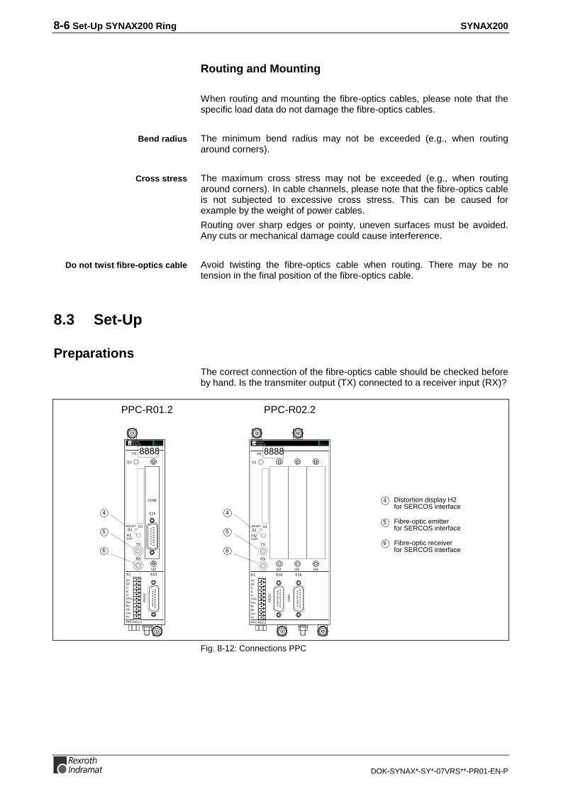
8-6 Set-Up SYNAX200 Ring SYNAX200
DOK-SYNAX*-SY*-07VRS**-PR01-EN-P
Routing and Mounting
When routing and mounting the fibre-optics cables, please note that thespecific load data do not damage the fibre-optics cables.
The minimum bend radius may not be exceeded (e.g., when routingaround corners).
The maximum cross stress may not be exceeded (e.g., when routingaround corners). In cable channels, please note that the fibre-optics cableis not subjected to excessive cross stress. This can be caused forexample by the weight of power cables.
Routing over sharp edges or pointy, uneven surfaces must be avoided.Any cuts or mechanical damage could cause interference.
Avoid twisting the fibre-optics cable when routing. There may be notension in the final position of the fibre-optics cable.
8.3 Set-Up
PreparationsThe correct connection of the fibre-optics cable should be checked beforeby hand. Is the transmiter output (TX) connected to a receiver input (RX)?
5
4
6
5
6
4
PPC-R02.2PPC-R01.2
6
5
4 Distortion display H2for SERCOS interface
Fibre-optic emitterfor SERCOS interface
Fibre-optic receiverfor SERCOS interface
PPC-R01.2
H1
PR
OG
U2X1
I1
I3I2
Q1Q2
24Ve0VeBbBb24V0V
S1
RX
TX
U1RESET
H2DIST
COM
X16
S2
X10
PPC-R02.2
H1
PR
OG
U2
X10X1
Q1Q2
24Ve0VeBbBb24V0V
S1
RX
TX
U1RESET
H2DIST
CO
M
X16
U3 U4
I1
I3I2
S2
RECO RECO
Fig. 8-12: Connections PPC
Bend radius
Cross stress
Do not twist fibre-optics cable

SYNAX200 Set-Up SYNAX200 Ring 8-7
DOK-SYNAX*-SY*-07VRS**-PR01-EN-P
X12
X11R
X
H3 ERR
X10T
XS3
HIG
HS2
LOW
Read and followInstructions for Electrical Drives"manual,DOK-GENERL-DRIVE******-SVS...
DANGHigh oltage.Danger of electrical shock.Do not touch electrical connectionsfo5 minutes after switching
8 */#!$#*!" */(%'
96*3$&:!(#*)#$"/*##&$6!$*"#&$6)&
96*3$&:!(#*)$&)&*0&$6!$*"#&$6)&
SY7PR029.FH7
01
2 3
45
6
78
90
1
2 3
45
6
78
9
Fig. 8-13: Connections DSS 2.1 (DIAX03/DIAX04)
Power connection
Motor connection
DKC**.3-040-7-FW
Bar
code
0 1
23
456
78
90 1
23
456
78
9
H1
S1
S3 S2
Bar
code
Type
nsch
ild
12
34
56
78
91
23
4
111213
141516
1718
56
78
12
34
56
78
XE2
XE1
L+
L-
L1
L2
L3
A1
A2
A3
X7:Programming module(Firmware, Parameter)H1 - Diagnosis indicatorS1 - Fault clearance buttonS2, S3 - Adress switch
7
3
2
1
ON
OFFS20
H20ERROR
321
X20
X21
TX
RX
Switch for setting the transmitter power
Switch for setting the data rate
H20: distortion display for SERCOS interface
X20: fibre-optic transmitter
X21: fibre-optic receiver
Fig. 8-14: Connections DKC02.3 (ECODRIVE03)

8-8 Set-Up SYNAX200 Ring SYNAX200
DOK-SYNAX*-SY*-07VRS**-PR01-EN-P
Setting Drive AddressThe address is set at every drive (see Fig. 8-13 or Fig. 8-14). It must beunique in each SYNAX200 ring. There may not be two drives with thesame address. Permitted addresses lie within the range of [1..40].
The machine can now be switched on.
Check Distortion DisplayThe next step is to check whether there is a sufficient optical level at eachparticipant, in other words, make sure that the receiver is neither over norunder-controlled.
Generally, the distortion display is dark (see Fig. 8-12, Fig. 8-13 or Fig. 8-14: LED H2, H3 ERR or H20). If it lights up, then the transmission path"ahead of" the participant must be checked.
Control - starting with the transmitter output of the control - in signaldirection, the distortion display of the drive (see Fig. 8-13 or Fig. 8-14).
The distortion display of the PPC is the LED H2 DIST. The distortiondisplay of the drives is LED "H3 ERR" or "H20".
Check the first drive in the ring. If its distortion display is dark, thenproceed to the next drive. This procedure is followed until the final driveand then the PPC is checked.
If one of the displays is not dark, then the following must be checked:
• has the transmission path been correctly set?
• has the output power of the previous drive in the ring been correctlyset?
• is the fibre-optics cable to the previous drive defective?
See section "Clearing Errors", chapter 8.4, for checking transmissionrates and output power.
8.4 Clearing Errors
Communications errors are signalled via the following diagnoses:
Dis-play
C-0-0048Errornumber
C-0-0047Diagnostics text
C-0-0046Diagnosticsinfo
F01 01 ""SERCOS interface - ring break" 10000h
F02 02 "SERCOS interface - no driveconnected"
10000h
F05 05 "SERCOS interface - double drivetelegram failure"
n = address
F06 06 "Fiber optic ring ring not closed" 10000h
F07 07 "drive addresses not correct(see C-0-0002, C-0-0086)"
10000h
Fig. 8-15: Error messages generated by communications errors
Distortion display may neitherlight up or glow!
Check distortion display in "lightdirection

SYNAX200 Set-Up SYNAX200 Ring 8-9
DOK-SYNAX*-SY*-07VRS**-PR01-EN-P
The causes could be:
• incorrectly set drive addresses
• incorrectly parametrized parameters C-0-0002 or C-0-0086
• incorrectly set transmission rates
• incorrectly set output power
• defective fibre-optics cable.
Use of Distortion DisplayA distortion display (see Fig. 8-12: "H2", Fig. 8-13: "H3 ERR" or Fig. 8-14:"H20") lights up in the following cases:
• incorrectly set transmission rate
• incorrectly set output power
• defective fibre-optics cable
If a distortion display does light up, then check:
The transmission rate must be checked at the PPC and the respectivedrive (see Fig. 8-16, Fig. 8-17).
Output power must be checked at the PPC and the physical predecessorsof the relevant drive (see Fig. 8-16, Fig. 8-17).
Check the fibre-optics cable from the physical predecessor to the relevantdrive.
Setting the Transmission RateThe transmission rate is set to 2 MBit/s. This is set at the time of deliveryfor both PPC and the drives so that generally speaking nothing has to beset here.
The transmission rate is set on the PPC in parameter "SERCOS interface- configuration" (C-0-0038). The contents of this parameter must equal’0000000000000000’.
The transmission rate is set with help of switch S4 on the communicationsboard DSS 2.1. For a transmission rate of 2 MBit/s the switch must be setto ’OFF’.
SY6PR031.FH7
S5 S4
DSS2.1
Fig. 8-16: DIP switch of the DSS 2.1 (DIAX03, DIAX04)
Checking the transmisison rate
Checking output power
Checking the fiber optic cable
PPC
DIAX03, DIAX04 (DSS 2.1)
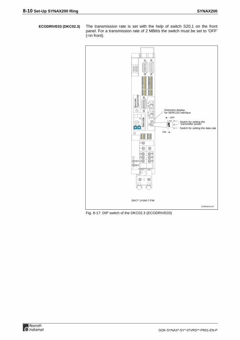
8-10 Set-Up SYNAX200 Ring SYNAX200
DOK-SYNAX*-SY*-07VRS**-PR01-EN-P
The transmission rate is set with the help of switch S20,1 on the frontpanel. For a transmission rate of 2 MBit/s the switch must be set to ’OFF’(=in front).
DKC**.3-040-7-FW
Bar
code
0 1
23
456
78
90 1
23
456
78
9
H1
S1
S3 S2
Bar
code
Type
nsch
ild
12
34
56
78
91
23
4
111213
141516
1718
56
78
12
34
56
78
XE2
XE1
L+
L-
L1
L2
L3
A1
A2
A3
7
3
2
1
ON
OFFS20
H20ERROR
321
X20
X21
TX
RX
Switch for setting the transmitter power
Switch for setting the data rate
Distortion displayfor SERCOS interface
Fig. 8-17: DIP switch of the DKC02.3 (ECODRIVE03)
ECODRIVE03 (DKC02.3)

SYNAX200 Set-Up SYNAX200 Ring 8-11
DOK-SYNAX*-SY*-07VRS**-PR01-EN-P
Setting the Optic Output Power
The output power of the PPC is parametrized using the parameters "fibre-optics cable (LWL) length" (C-0-0007). If plastic fibre-optics cables areused, then the length of the fibre-optics cable connected to thetransmission output is set here. With glass fibre-optics cables, a length of50.0 m must be set here.
Output power is set via switches S5A and S5B on the DSS 2.1 card (seeFig. 8-16).
Output power is set via switches S20,2 and S20,3 on the front panel (seeFig. 8-17).
If plastic fibre-optics cables are used then see Fig. 8-18. If glass fibre-optics cables are used then see Fig. 8-19.
Fibre-opticscable length
0 .. 15 m 15 m ..30 m 30 m .. 50 m
DIAX03, DIAX04 S5A = OFF
S5B = OFF
S5A = ON
S5B = OFF
S5A = ON
S5B = ON
DKC02.3 S20,2 = OFF
S20,3 = OFF
S20,2 = ON
S20,3 = OFF
S20,2 = ON
S20,3 = ON
Fig. 8-18: Setting the output power with plastic fibre-optics cables
Fibre-optics cable length 0 .. 500 m
DIAX03, DIAX04 S5A = ON / S5B = ON
DKC02.3 S20,2 = ON / S20,3 = ON
Fig. 8-19: Setting the output power with glass fibre-optics cables
Checking the Fibre-Optics CablesIf both transmission rates and output power have been correctly set, (seesection "Clearing Errors", chapter 8.4) and communications still will notfunction, then it is possible that the fibre-optics cable has a defect. In thiscase, the distortion display will also light up.
The cause of a defective fibre-optics cable can be damage or poormanufacture (e.g., connector mounting).
A defective fibre-optics cable can possibly be recognized by the fact thatat the end of the fibre-optics cable hardly any light is visible or the opticalfibre has been "pulled in backwards" into the connector. Check the face ofthe connector. Other fibre-optics cable checks cannot be conductedwithout the appropriate tools.
The only remedial action is the exchange of the defective fibre-opticscable.
PPC
DIAX03, DIAX04 (DSS 2.1)
ECODRIVE03 (DKC02.3)

8-12 Set-Up SYNAX200 Ring SYNAX200
DOK-SYNAX*-SY*-07VRS**-PR01-EN-P

SYNAX200 PPC Link 9-1
DOK-SYNAX*-SY*-07VRS**-PR01-EN-P
9 PPC Link
9.1 General Information
Several PPC motion controls can be combined to create one PPC linkwith which the following axes can be assigned to different master axes
This combination of PPC motion controls is accomplished with the help ofPPC plug-in card DAQ. All DAQ boards are connected with a fibre-opticscable (LWL) ring thereby creating the PPC link.
Communications within the PPC link implements, as does the SYNAX200ring, a fibre-optics cable ring.
The PPC link can be built on a simple or double LWL ring.
The DAQ board DAQ03 supports not only double but single rings as well.
94
8
7
;+
948
9
<5<<
9
9
945
9
9
9
)!""&)#*!"
=$& '=
>?=&$$!$($*$'$*"1=>?=&$$!$/&)!" $'$*"1=5>?=/%0&)*$)-*#=>?=/#&$)*$)-*#=
@/&)!" $'$*"1
@($*$'$*"1
8
8
Fig. 9-1: Front view of plug-in card DAQ03
Up to 32 PPC motion controls can be combined to one PPC link.
Each link participant receives a link address. The link address is set viaparameter "PPC link - address" (C-0-0179).
The link address must be within a range 1 ... 32.
Simple and double ring
Plug-in card DAQ
Max. 32 PPCs in a link
Link addresses

9-2 PPC Link SYNAX200
DOK-SYNAX*-SY*-07VRS**-PR01-EN-P
9.2 PPC Link with Simple Ring
link ring
PPC-R +DAQ
SYNAX ring 1
SYNAX ring 2
SYNAX ring 3
PPC-R + DAQ
PPC-R + DAQ
$*0&
$*0&5 $*0&
A
$*0&
$*0&5
$*0&
$*0&
$*0&5
$*0&"
PPC-R02.2
H1
PR
OG
U2
X10X1
Q1Q2
24Ve0VeBbBb24V0V
S1
RX
TX
U1RESETS2
H2DIST
CO
M
X16
U3 U4
I1
I3I2
RECO
PPC-R02.2
H1
PR
OG
U2
X10X1
Q1Q2
24Ve0VeBbBb24V0V
S1
RX
TX
U1RESETS2
H2DIST
CO
M
X16
U3 U4
I1
I3I2
RECO
PPC-R02.2
H1
PR
OG
U2
X10X1
Q1Q2
24Ve0VeBbBb24V0V
S1
RX
TX
U1RESETS2
H2DIST
CO
M
X16
U3 U4
I1
I3I2
RECO
Fig. 9-2: PPC link with single ring
A simple ring only uses the primary ring. The secondary ring is not built.
9489
9
9
9459
9
9
88 8
9459
9489
9459
9489
9
9
9
9
9
9
9
9
4
Fig. 9-3: LWL link in a simple ring
Simple ring: primary ring

SYNAX200 PPC Link 9-3
DOK-SYNAX*-SY*-07VRS**-PR01-EN-P
9.3 PPC Link With Double Ring
PPC-R + DAQ
SYNAX ring 1
SYNAX ring 2
SYNAX ring 3
PPC-R + DAQ
PPC-R + DAQ
secondaryring
primary ring
$*0&
$*0&5 $*0&
A
$*0&
$*0&5
$*0&
$*0&
$*0&5
$*0&"
7
PPC-R02.2
H1
PR
OG
U2
X10X1
Q1Q2
24Ve0VeBbBb24V0V
S1
RX
TX
U1RESETS2
H2DIST
CO
M
X16
U3 U4
I1
I3I2
RECO
PPC-R02.2
H1
PR
OG
U2
X10X1
Q1Q2
24Ve0VeBbBb24V0V
S1
RX
TX
U1RESETS2
H2DIST
CO
M
X16
U3 U4
I1
I3I2
RECO
PPC-R02.2
H1
PR
OG
U2
X10X1
Q1Q2
24Ve0VeBbBb24V0V
S1
RX
TX
U1RESETS2
H2DIST
CO
M
X16
U3 U4
I1
I3I2
RECO
Fig. 9-4: PPC link with double ring
The primary ring is generally used for communication. The secondary ringonly transmits diagnostics signals.
Note: The secondary ring must be connected - as shown - in acounter direction.
9489
99
9459
99
88 8
9459
9489
9459
9489
99
9
9
99
99
Fig. 9-5: LWL connections in a double ring
Primary ring, secondary ring

9-4 PPC Link SYNAX200
DOK-SYNAX*-SY*-07VRS**-PR01-EN-P
9.4 Configuration Example with PPC
With an eye towards increased machine availability PPC motion controlscan become an own 24V electronic storage. So they can be supported aswith master system UPS = uninterruptable power source.
SYNAX ring 3SYNAX ring 1 SYNAX ring 2
RECO
RECO
B
RECO
PPC PPC PPC
%*"A$*"1
DAQ
Fig. 9-6: Double ring configuration with PPC
9.5 Commissioning the PPC Link
General InformationEach PPC needs a different link address. The link address is set withparameter "PPC link - address" (C-0-0179).
The PPC link is parametrized via SynTop. An active PPC link is displayedon the DAQ03 using the H11 or H12 display.
The optical transmission power of the primary or secondary rings isparametrized using SynTop.
Using the distortion display of the DAQ (DAQ03.1R: LEDs H17 or H18) itis possible to check the quality of the optical receive signal.
Link address
Parametrization
Setting optical transmissionpower
Distortion display

SYNAX200 PPC Link 9-5
DOK-SYNAX*-SY*-07VRS**-PR01-EN-P
CommissioningFirst the PPC link and the fibre-optics lengths are parametrized viaSynTop and the PPCs are brought into operating mode.
The active PPC link is displayed on displays H11 or H12 at each PPCusing the parametrized PPC link. (Precisely one link master and severallink slaves).
The H17 and H18 distortion displays must be checked and if necessarythe transmission power of the immediate physical predecessor must becorrected or the fibre-optics lead checked for any damage.
In the case of a parametrized simple ring (no double ring) the H18distortion displays will light up. This state is correct.
Clearing ErrorsPPC link problems are signalled with binary PPC outputs and thefollowing diagnoses
Dis-play
C-0-0048Errornumber
C-0-0047Diagnostic text
C-0-0046Diagnosticinformation
F40 40 "PPC link - transmission pathdefective"
10000h
F42 42 "PPC link - master position fault(MDT)"
10000h
F43 43 "PPC link - master position fault(AT)"
n = address
F44 44 "PPC link - link address set - notpermitted"
10000h
F93 93 "DAQ: SERCOS interface - ASIC:intialization error"
10000h
F15 190 "PPC link - other link master alreadyactive"
10000 h
Fig. 9-7: Error messages with PPC link errors
In such cases, the H11, H12, H17 and H18 displays can be used to locatethe cause.
Causes can be:
• incorrectly set transmission power of primary and secondary rings
• wrong parametrization of PPC link (simple ring, double ring, no PPClink)
• defective fibre-optics cable.

9-6 PPC Link SYNAX200
DOK-SYNAX*-SY*-07VRS**-PR01-EN-P

SYNAX200 Set-Up Interfaces 10-1
DOK-SYNAX*-SY*-07VRS**-PR01-EN-P
10 Set-Up Interfaces
10.1 General Information
The PC set-up software SynTop is connected to the PPC by means of aserial interface. This uses the PPC interface X10 or X16. The choice ofthe interface can be made using a parameter. The interface X10 isgalvanic seperated and therefore it should be used preferably.
10.2 Connecting the PPC
Use the standard control cable IKB0005 to connect the PPC.
2
pin
3
7
signal
TxDRxD
SGND
15 pin D-subminiature, connector
PPC (X10, X16) terminal / PC
2
pin signal
378546
RxDTxDRTSCTSSGNDDTRDSR
connectorhousing
9-pin D-subminiature, bushing
SY7PR057.FH7
connectorhousing
Fig. 10-1: IKB0005
585
'"!(
4
PPC-R02.2
H1
PR
OG
X10
RECO
Fig. 10-2: Connecting SynTop to the PPC

10-2 Set-Up Interfaces SYNAX200
DOK-SYNAX*-SY*-07VRS**-PR01-EN-P
10.3 RS485 Link
SynTop can communicate with many PPCs using an RS485 link.
4
585
'"!(
C
4D
5
6-$#2&$9$*"1/
/#&$*/%*"A
PPC-R02.2
H1
PR
OG
X10
RECO
PPC-R02.2
H1
PR
OG
X10
RECO
Fig. 10-3: RS485 link of SynTop to multiple PPCs
This necessitates couplers from RS485 to RS232 for the connection ofthe PC to the RS485 link.
An example is the coupler interface module PSM-EG-RS232/RS485-P/2Dmade by Phoenix Contact.
Interface Module PSM-EG-RS232/RS485-P/2DThe RS485 directional switches of the module uses the RTS signal. withthese cables the TxD of the sender is connected to the RTS of themodule, i.e. with each 1 bit there is a switch to transmit.
Switch settings:
• 180R BUS-END ON (only at the end of the bus)
• S1 on DTE
• RTS/CTS high-active (bridge jumper X6 from pin 3 to pin 4)
With switch 180R BUS-END a matching resistor 180R and each 470Ragainst +5V and GND can be connected to the bus end.
The voltage supply for the interface modules comes from 24 V which isconnected via the intended screw-in clamps.

SYNAX200 Set-Up Interfaces 10-3
DOK-SYNAX*-SY*-07VRS**-PR01-EN-P
The cable from interface module to PC is constructed as follows:
32
4
9-pin, bushing
TxDRxD
DTR
RS232 cable from PC to converter
SY7PR060.FH7
87
CTSRTS
5GND6DSR
PSM-EG.: D-Sub
32
4
TxDRxD
DTR
87
CTSRTS
5GND6DSR
9-pin, bushingPC side: D-subminiature
connectorhousing
connectorhousing
Fig. 10-4: RS232 cable from PC to converter
RS485 Connection of the PPCs
PPC-R02.2
PR
OG
X10
RECO
C4
4:4C
9!$97
4
4
5
D
Fig. 10-5: RS485 connection of the PPC
RS485 Connection of the Interface ModuleOn RS485, the D(A) and D(B) are twisted in pairs and connected. GND isalso connected. These can be connected to the interface module usingeither screw-in clamps or male D-subminiature 9-pin connectors (bushingis on the module).
Connector: D(A) data negative pin 8, D(B) data positive pin 3, GND pin2.
Cable converter <->PC

10-4 Set-Up Interfaces SYNAX200
DOK-SYNAX*-SY*-07VRS**-PR01-EN-P
83
9-pin, pins
D(A)D(B)
RS485 cable between PSM-EG and PPC
SY7PR062.FH7
2GND
PSM-EG.: D-subminiature
54
D(A)D(B)
15-pin, pinsPPC: D-subminiature
7GND
5D(A)4D(B)
7GND
D(A) and D(B)twisted in pairs
D-sub15 bushingto the next PPC
connectorhousing
connetorhousing
RS485-
RS485+
Fig. 10-6: RS485 cable between converter PSM-EG and PPC
RS485 CableThe RS485 bus cable should be shielded and twisted in pairs. Thediameter should equal at least 0.22mm2, with a characteristic impedanceof 100-120Ω.
The shield is applied at both ends of the transmission path. Ifequipotential currents are expected, then one side is directly groundedand the other is grounded via a 15nF capacitor.
Bus MatchingThe bus matching must be effected on both bus ends. If a bus end isconstructed with RS485 coupler above, then the bus matching in thecoupler can be connected via switch in the coupler.
Power supply of the bus machting can also be received by the PPC.
C4
4:
4C
8DΩ
4Ω
8DΩ
Fig. 10-7: Power supply of the bus matching via PPC

SYNAX200 Appendix 11-1
DOK-SYNAX*-SY*-07VRS**-PR01-EN-P
11 Appendix
11.1 Dimensional Sheets, Terminal Diagrams RECO
Mounting Dimensions Module Carrier RMB02.2-02
9
12
4,5
2,25
98
42 42
217
120
47
77
Tophat rail
TS35 x27 x15
54.5
5672
Screw for lockingthe subrack onthe tophat rail
Fig. 11-1: Module carrier RMB02.2-02

11-2 Appendix SYNAX200
DOK-SYNAX*-SY*-07VRS**-PR01-EN-P
Mounting Dimensions Module Carrier RMB02.2-04
S1
182
42 121
217
120
47
77
Tophat railTS 35 x 27 x15
54,5
562 7
9
12
4,5
2,25
Screw for lockingthe subrack on thetophat rail
Fig. 11-2: Module carrier RMB02.2-04
42
182
121
182
4712
0
217
182
S1 S1
Fig. 11-3: Side-by-side installation of several RMB02.2-04 module carrier

SYNAX200 Appendix 11-3
DOK-SYNAX*-SY*-07VRS**-PR01-EN-P
PPC-R01.2 and PPC-R02.2
PPC-R02.2PPC-R01.2
22 126,5
165
41,5 83,7 4,5
192
214
11
RECO
PPC-R01.2
H1
PR
OG
U2X10X1
I1
I3I2
Q1Q2
24Ve0VeBbBb24V0V
S1
RX
TX
U1RESETS2
H2DIST
PPC-R02.2
H1
PR
OG
U2
X10X1
Q1Q2
24Ve0VeBbBb24V0V
S1
RX
TX
U1RESETS2
H2DIST
CO
M
X16
U3 U4
I1
I3I2
RECO
Bemaßung.FH7
Fig. 11-4: Dimensioanl sheet PPC-R01.2 and PPC-R02.2
ca. 235
ca. 300
56,5
2
247,
55
40,5
5
54,5
1515
ca. 183
RMB
Mounting railTS 35 x 27 x 15
Bemaßung_Einbau.FH7
Fig. 11-5: Mouting dimensions PPC-R01.2 and PPC-R02.2
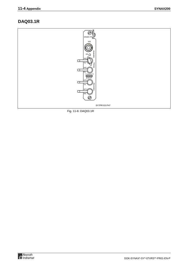
11-4 Appendix SYNAX200
DOK-SYNAX*-SY*-07VRS**-PR01-EN-P
DAQ03.1R
8
8
94
7
;+
945
9 $*
$'948
9<5<<
&)!" $'
9
9
9
9
Fig. 11-6: DAQ03.1R

SYNAX200 Appendix 11-5
DOK-SYNAX*-SY*-07VRS**-PR01-EN-P
Profibus Interface DPS01
4
!"#$%&'"
#PROFIBUS interface (slave)
PROFIBUS diagnosis interface RS232 C (project planning interface)
(
)
*
+
Fig. 11-7:Profibus interface DPS01

11-6 Appendix SYNAX200
DOK-SYNAX*-SY*-07VRS**-PR01-EN-P
INTERBUS Interface IBS03
SY7PR106.FH7
INTERBUS interface (in coming) (slave)
INTERBUS interface (out going)
+*$%&'"
(
;
;
Fig. 11-8: INTERBUS interface IBS03

SYNAX200 Appendix 11-7
DOK-SYNAX*-SY*-07VRS**-PR01-EN-P
DeviceNet Interface DNS03
;
DeviceNet diagnosis interface RS232 C (project planning interface)
DeviceNet interface (slave)
+(
Fig. 11-9: DeviceNet interface DNS03

11-8 Appendix SYNAX200
DOK-SYNAX*-SY*-07VRS**-PR01-EN-P
RME02.2-16-DC024 Input Module
Brief DescriptionThe digital 24 VDC input modules are designed for connecting digitalcontrol signals that are produced by pushbuttons, limit switches orelectronic proximity switches. The 16 inputs are arranged in 2 isolatedpotential groups.
Mounting Dimensions
41,3
192
214
57,54,3
12
3623,5
total installation depth incl. base rack ca. 150
RME02.2-16-DC024_Maß.FH7
Fig. 11-10: Mounting dimensions RME02.2-16-DC024

SYNAX200 Appendix 11-9
DOK-SYNAX*-SY*-07VRS**-PR01-EN-P
Pin Assignments
,"-./. -0.%123
- Low: -10V ... +8V- High: +17 ... +30V- Input current IE High < 10mA- Power loss Pv ca. 4W- Weight ca. 290g
1
2
3
4
5
6
7
8
9
10
RME02.2-16-DC024
0VL
0VL
GND
RE
- +
+UL = 24VDC
*.0.0
*.0.1
*.0.2
*.0.3
*.0.4
*.0.5
*.0.6
*.0.7
*.1.1
*.1.2
*.1.3
*.1.4
*.1.5
*.1.6
*.1.7
*.1.0
RME02.2-16-DC024_Anschl.fh7
Fig. 11-11: Wiring diagram RME02.2-16-DC024

11-10 Appendix SYNAX200
DOK-SYNAX*-SY*-07VRS**-PR01-EN-P
RME02.2-32-DC024 Input Module
Brief DescriptionThe digital 24 VDC input modules are designed for connecting digitalcontrol signals that are produced by pushbuttons, limit switches orelectronic proximity switches. The 32 inputs are arranged in 4 isolatedpotential groups.
Mounting Dimensions
41,3
192
214
57,54,3
11
3523,5
total installation depth incl. base rack ca. 150
RME02.2-32-DC024_Maß.FH7
Fig. 11-12: Mounting dimensions RME02.2-32-DC024

SYNAX200 Appendix 11-11
DOK-SYNAX*-SY*-07VRS**-PR01-EN-P
Pin Assignments
1
2
3
4
5
6
7
8
9
RME02.2-32-DC024
0VL
,"-./.- 0.%123
- Low: -10V ... +8V- High: +17 ... +30V- Input current IE High < 10mA- Power loss ca. 2,5W- Weight ca. 300g
GND
RE
+-
+UL= 24 VDC
*.0.0
*.0.1
*.0.2
*.0.3
*.0.4
*.0.5
*.0.6
*.0.7
*.1.1
*.1.2
*.1.3
*.1.4
*.1.5
*.1.6
*.1.7
*.1.0 *.2.0
*.2.1
*.2.2
*.2.3
*.2.4
*.2.5
*.2.6
*.2.7
*.3.1
*.3.2
*.3.3
*.3.4
*.3.5
*.3.6
*.3.7
*.3.0
RME02.2-32-DC024_Anschl.FH7
Fig. 11-13: Wiring diagram RME02.2-32-DC024

11-12 Appendix SYNAX200
DOK-SYNAX*-SY*-07VRS**-PR01-EN-P
RME02.2-16-AC115 Input Module
Brief DescriptionAC sources of a maximum rating of 120VAC / 60Hz can directly beconnected to the digital 115VAC input modules. The 16 AC inputs arearranged in 2 isolated potential groups.
Mounting Dimensions
41,3
192
214
57,54,3
12
23,5 ca.36
total installation depth incl. base rack ca. 150
RME02.2-16-AC115-Maß.FH7
Fig. 11-14: Mounting dimensions RME02.2-16-AC115

SYNAX200 Appendix 11-13
DOK-SYNAX*-SY*-07VRS**-PR01-EN-P
Pin Assignments
1
2
3
4
5
6
7
8
9
10
RME02.2-16-AC115
COM
COM
GND
ZE
*.0.0
*.0.1
*.0.2
*.0.3
*.0.4
*.0.5
*.0.6
*.0.7
*.1.1
*.1.2
*.1.3
*.1.4
*.1.5
*.1.6
*.1.7
*.1.0,"-./.- 0.%123
- Low: < 35V AC- High: 85 ... 138V AC- Input current IE High < 15mA- Power loss Pv ca. 3W- Weight ca. 300g
115VAC
N L1
RME02.2-16-AC115_Anschl.FH7
Fig. 11-15: Wiring diagram RME02.2-16-AC115

11-14 Appendix SYNAX200
DOK-SYNAX*-SY*-07VRS**-PR01-EN-P
RMA02.2-16-DC024-200 Output Module
Brief DescriptionThe digital 24VDC output modules are designed for the connection ofdigital actuators, such as solenoid valves, contactors, or indicator lights.The 16 outputs are FET transitor switches (active 1 switching) that arearranged in 2 isolated groups of 8 outputs each. Each 24V output cansource loads up to 2 A.
Mounting Dimensions
41,3
192
214
57,54,3
12
3623,5
total installation depth incl. base rack ca. 150
RMA02.2-16-DC024-200_Maß.FH7
Fig. 11-16: Mounting dimensions RMA02.2-16-DC024-200

SYNAX200 Appendix 11-15
DOK-SYNAX*-SY*-07VRS**-PR01-EN-P
Pin Assignments
,"-./.- 0.%123
- FET - output switch for 24V DC- output current IL = 2A per output- internal current limitation- short-circuit-proof- 2 isolated blocks
with 8 outputs each- with internal voltage monitoring of
the externally applied voltage- power loss Pv ca. 7,5W- weight ca. 280g
1
2
3
4
5
6
7
8
11
12
RMA02.2-16-DC024-200
+UL
0VL
9
10 +UL
0VL
+ +
-
= 24 VDC
externalpowersupply
Q*.0.0
Q*.0.1
Q*.0.2
Q*.0.3
Q*.0.4
Q*.0.5
Q*.0.6
Q*.0.7
Q*.1.0
Q*.1.1
Q*.1.2
Q*.1.3
Q*.1.4
Q*.1.5
Q*.1.6
Q*.1.7
RMA02.2-16-DC024-200_Anschl.FH7
Fig. 11-17: Wiring diagram RMA02.2-16-DC024-200

11-16 Appendix SYNAX200
DOK-SYNAX*-SY*-07VRS**-PR01-EN-P
RMA02.2-32-DC024-050 Output Module
Brief DescriptionThe digital 24VDC output modules are designed for the connection ofdigital actuators, such as solenoid valves, contactors, or indicator lights.The 32 outputs are FET transitor switches (active 1 switching) that arearranged in 4 isolated groups of 8 outputs each. Each 24V output cansource loads up to 500 mA.
Mounting Dimensions
41,3
192
214
23,5 57,54,3
11
35
total installation depth incl. base rack ca. 150
RMA02.2-32-DC024-050_Maß.FH7
Fig. 11-18: Mounting dimensions RMA02.2-32-DC024-050

SYNAX200 Appendix 11-17
DOK-SYNAX*-SY*-07VRS**-PR01-EN-P
Pin Assignments
,"-./.- 0.%123
- FET - output switch for 24V DC- output current IL = 0.5A per output- internal current limitation- short-circuit-proof- 4 isolated blocks with 8 outputs each- with internal voltage monitoring of the
externally applied voltage- power loss Pv ca. 2,5W- weight ca. 300g
RMA02.1-32-DC024-050
1
2
3
4
5
6
7
8
9
10+ +
-
Q*.3.0 Q*.2.0 Q*.1.0 Q*.0.0
Q*.3.1 Q*.2.1 Q*.1.1 Q*.0.1
Q*.3.2 Q*.2.2 Q*.1.2 Q*.0.2
Q*.3.3 Q*.2.3 Q*.1.3 Q*.0.3
Q*.3.4 Q*.2.4 Q*.1.4 Q*.0.4
Q*.3.5 Q*.2.5 Q*.1.5 Q*.0.5
Q*.3.6 Q*.2.6 Q*.1.6 Q*.0.6
Q*.3.7 Q*.2.7 Q*.1.7 Q*.0.7
+UL = 24 VDC
0VL
externalpowersupply
RMA02.2-32-DC024-050_Anschl.FH7
Fig. 11-19: Wiring diagram RMA02.2-32-DC024-050
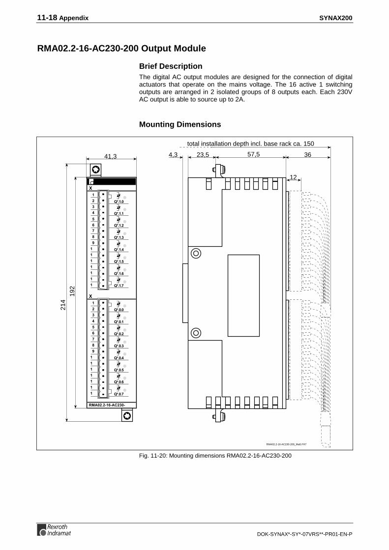
11-18 Appendix SYNAX200
DOK-SYNAX*-SY*-07VRS**-PR01-EN-P
RMA02.2-16-AC230-200 Output Module
Brief DescriptionThe digital AC output modules are designed for the connection of digitalactuators that operate on the mains voltage. The 16 active 1 switchingoutputs are arranged in 2 isolated groups of 8 outputs each. Each 230VAC output is able to source up to 2A.
Mounting Dimensions
41,3
192
214
57,54,3
12
3623,5
total installation depth incl. base rack ca. 150
RMA02.2-16-AC230-200_Maß.FH7
Fig. 11-20: Mounting dimensions RMA02.2-16-AC230-200

SYNAX200 Appendix 11-19
DOK-SYNAX*-SY*-07VRS**-PR01-EN-P
Pin Assignments
,"-./.- 0.%123
- Switching voltage:UA = 12 ... 275Vrms AC / 10 ... 440Hz
- Switching current:IAmax = 2AIAmin = 5mA
- Power loss Pv ca. 12,8W- Weight ca. 600g
1
RMA02.2-16-AC230-200
UACQ*.1.02
3
4
5
6
7
8
9
10
11
12
13
14
15
16
COMUACCOM
Q*.1.1
Q*.1.2
Q*.1.3
Q*.1.4
Q*.1.5
Q*.1.6
Q*.1.7
Q*.0.0
Q*.0.1
Q*.0.2
Q*.0.3
Q*.0.4
Q*.0.5
Q*.0.6
Q*.0.7
RMA02.2-16-AC230-200_Anschl.FH7
UU
UU
UU
UU
Fig. 11-21: Wiring diagram RMA02.2-16-AC230-200

11-20 Appendix SYNAX200
DOK-SYNAX*-SY*-07VRS**-PR01-EN-P
RMA02.2-16-RE230-200 Output Module
Brief descriptionThe digital relay output modules are designed as floating switchingcontacts for AC and DC. The 16 active 1 switching outputs are arrangedin 2 isolated groups of 8 outputs each. Depending on the load, themaximum switching capacity of each output is between 50W and 200W.
Mounting Dimensions
41,3
192
214
57,54,3
12
3623,5
total installation depth incl. base rack ca. 150
RMA02.2-16-RE230-200_Maß.FH7
Fig. 11-22: Mounting dimensions RMA02.2-16-RE230-200

SYNAX200 Appendix 11-21
DOK-SYNAX*-SY*-07VRS**-PR01-EN-P
Pin Assignments
1
RMA02.2-16-RE230-200
+U od. L10V od. N
2
3
4
5
6
7
8
9
10
11
12
13
14
15
16
+U od. L10V od. N
,"-./.- 0.%123
- switching voltage: UA max = 230Veff- switching power: PA max = 50W ... 220W
(voltage-dependent)- power loss: Pv ca. 4W- weight ca. 440g
Q*.1.0
Q*.1.1
Q*.1.2
Q*.1.3
Q*.1.4
Q*.1.5
Q*.1.6
Q*.1.7
Q*.0.0
Q*.0.1
Q*.0.2
Q*.0.3
Q*.0.4
Q*.0.5
Q*.0.6
Q*.0.7
RMA02.2-16-RE230-200_Anschl.FH7
Fig. 11-23: Wiring diagram RMA02.2-16-RE230-200

11-22 Appendix SYNAX200
DOK-SYNAX*-SY*-07VRS**-PR01-EN-P
11.2 Dimensional Sheet, Terminal Diagrams Drives
SERCOS interface DSS02.1M
E1
E2
E3
E4
E5
E6
+UL0VL
9pin plug-in screw clamppart no.: 241 591
1
2
3
4
5
6
7
8
9
TX
X10
FSMA connector 2,2 ø INS0420/F026,0 ø INS0425/F02
fiber-optic interfacetransmitter
SY6PR074.FH7
looking towards front panel
DS
S 0
2.1
H3 ERR
+UL
0VL
E4
E5
E3
E2
E1
X 1
2X
11
X 1
0S
3LO
WS
2R
XT
XH
IGH
01
2 3
45
6
78
90
1
2 3
45
6
78
9
reference switch
pos. travel range limit switch
neg. travel range limit switch
probe 1
probe 2
E-STOP
DC +24V ext.
DC 0V ext.
RX
X11
X12
fiber-optic interfacereceiver
1
2
3
4
5
6
7
8
9
E6
Mdistortion display(see section 8.3 "Commissioning")
Fig. 11-24: Terminal diagram DSS02.1M

SYNAX200 Appendix 11-23
DOK-SYNAX*-SY*-07VRS**-PR01-EN-P
Input / Output interface DEA
DEA04.2M, DEA05.2M, DEA06.2M
DC 24 Vext
SY6PR040.FH7
looking towards front panel
X17/X32/X33
inputs
outputs
IKS4123
ready-madecable IKS4123
free
free
0Vext
free
Uext
1
2
3
4
5
6
7
8
9
10
11
12
13
14
15
16
17
18
19
20
21
22
23
24
25
26
27
28
29
30
31
32
33
34
35
36
37
IN 0
IN 1
IN 2
IN 3
IN 4
IN 5
IN 6
IN 7
IN 8
IN 9
IN 10
IN 11
IN 12
IN 13
IN 14
OUT 0
OUT 1
OUT 2
OUT 3
OUT 4
OUT 5
OUT 6
OUT 7
OUT 8
OUT 9
OUT 10
OUT 11
OUT 12
OUT 13
OUT 14
OUT 15
CLC_Bb
BKGN
GYPK
RDGN
BKYE
GNBU
RDBU
BNYE
BNGY
RDWH
WHPK
BKWH
BNPK
YEWH
GNWH
BUWH
GNGY
GYWH
WH
VT
YE
PK
BU
YEGY
GNPK
YEPK
BNBU
BNGN
YEBU
RDYE
BNRD
BKBN
BN
BK
GY 0,5 mm2
RD
GN 0,5 mm2
GNYE 0,5 mm2
DC 0 Vext
ferrules for intermediate clamping
200
DEA05.2
INK0271
connector INS0523/L01
45
DE
A06
.2
M
ERR
X 33
DE
A04
.2
M
ERR
X 17
DE
A05
.2
M
ERR
X 32
DE
A05
.2
M
ERR
X 32
Fig. 11-25: Terminal diagram DEA04.2M, DEA05.2M, DEA06.2M

11-24 Appendix SYNAX200
DOK-SYNAX*-SY*-07VRS**-PR01-EN-P
DEA08.1M, DEA09.1M, DEA10.1M
Ap5223f1.fh7
X64 / X65 / X66ready-made cable IKS4186
1234567891011121314151617181920212223242526272829303132333435363738394041424344454647484950515253545556575859606162
DE
A08
.1
M
X 64
ERR
DE
A09
.1
M
X 65
ERR
DE
A10
.1
M
X 66
ERR
looking towardsfront panelIKS4186
ferrules forintermediate clamping
400 INK0598 connectorINS0620/L01
72
BU/RD 0.16 mm2
GN/WH 0.16 mm2
BN/GN 0.16 mm2
YE/WH 0.16 mm2
BN/YE 0.16 mm2
GY/WH 0.16 mm2
BN/GY 0.16 mm2
WH/PK 0.16 mm2
BN/PK 0.16 mm2
BU/WH 0.16 mm2
BU/BN 0.16 mm2
BK/GY 0.21 mm2
BK/PK 0.21 mm2
BK/BU 0.21 mm2
BK/RD 0.21 mm2
BK/BN/WH 0.21 mm2
BK/YE/GN 0.21 mm2
BK/GY/PK 0.21 mm2
BK/RD/BU 0.21 mm2
WH2 0.5 mm2
WH3 0.5 mm2
RD/WH 0.16 mm2
BN/RD 0.16 mm2
BK/WH 0.16 mm2
BK/BN 0.16 mm2
GN/GY 0.16 mm2
YE/GY 0.16 mm2
PK/GN 0.16 mm2
YE/PK 0.16 mm2
GN/BU 0.16 mm2
BK/GN/WH 0.21 mm2
BK/BN/GN 0.21 mm2
BK/YE/WH 0.21 mm2
BK/BN/YE 0.21 mm2
BK/GY/WH 0.21 mm2
BK/BN/GY 0.21 mm2
BK/WH/PK 0.21 mm2
BK/BN/PK 0.21 mm2
BK/BU/WH 0.21 mm2
WH4 0.5 mm2
WH5 0.5 mm2
In 0In 1In 2In 3In 4In 5In 6In 7In 8In 9In 10Out 0Out 1Out 2Out 3Out 4Out 5Out 6Out 7
CLC_Bb0Vext.In 11In 12In 13In 13In 15In 16In 17In 18In 19In 20In 21Out 8Out 9Out 10Out 11Out 12Out 13Out 14Out 15+Uext.0Vext.In 22In 23In 24In 25In 26In 27In 28In 29In 30In 31
Out 16Out 17Out 18Out 19Out 20Out 21Out 22Out 23+Uext0Vext
43 22 1
62 42 21
connect shield via cable gripwith metal connector housing
WH 0.16 mm2
BN 0.16 mm2
GN 0.16 mm2
YE 0.16 mm2
GY 0.16 mm2
PK 0.16 mm2
BU 0.16 mm2
RD 0.16 mm2
BK 0.16 mm2
VT 0.16 mm2
GY/PK 0.16 mm2
YE/BU 0.21 mm2
RD/GN 0.21 mm2
RD/YE 0.21 mm2
BK/GN 0.21 mm2
BK/YE 0.21 mm2
BU/GY 0.21 mm2
BU/PK 0.21 mm2
RD/GY 0.21 mm2
PK/RD 0.21 mm2
WH1 0.5 mm2
58,0
The colour code is correct forINDRAMAT cable type: INK0598
Fig. 11-26: Terminal diagram DEA08.1M, DEA09.1M, DEA10.1M

SYNAX200 Appendix 11-25
DOK-SYNAX*-SY*-07VRS**-PR01-EN-P
Encoder interface DAG01.2M (EnDat or SSI interface)
SY6PR072.FH7
looking towardsfront panel
1
2
15
4
17
19
6
7
Encoder interface with EnDat interface
DA
G 0
1.2
25-pin D-sub. connector INS0520/L01(screw mounting) X59 X59
0 V sensor
+5 V sensor
0 V
+5 V
data (-)
data (+)
pulse (-)
pulse (+)
0 V ext.
24 V ext.
free
A+
A-
B+
B-
shield
R+
R-
4-pin plug-in screw clamppart no.: 254006
24 V ext.
0 V ext.
Schirm
frei
1
2
3
4
+UL0VL
1
2
3
4
X58
13
1
25
14
X58
If an EnDat interface hasbeen selected then do not
connect voltage supply!
BKGN
BKYE
BKBU
BKRD
RD
BK
WH
BU
GNWH
BNGN
PK
GY
YE
VT
15
16
12
13
11
3
2
16
18
3
5
20
21
22
23
24
25
enocder
A+
A-
B+
B-
shield
R+
R-
4
1
10
7
17
14
9
8
0 V sensor
+5 V sensor
0 V
+5 V
data (-)
data (+)
pulse (-)
pulse (+)
join to connector housing
connect shield with metalhousing via cable grip
Color coding applies to ready-made INDRAMAT cable: IKS4142
8::14
free::free
1
2
15
4
17
19
6
7
16
18
3
5
20
21
22
23
24
25
8::
14
M
Fig. 11-27: Terminal diagram DAG01.2M

11-26 Appendix SYNAX200
DOK-SYNAX*-SY*-07VRS**-PR01-EN-P
Analog interface with Actual Position Value Output DAE02.1M
E1+
E1-
TVW
RF
AH
E2+
E2-
+UL
OVL
CLR
STOP
FB+
FB-
12
SY6PR054.FH7
looking towardsfront panel
14-pin plug-in, screw clamp, part no.: 274838
± 10V analog input 1
clear error
stop
pos. travel range limit switch
neg. travel range limit switch
DC +24V ext.
DC 0V ext.
8
1
3
4
5
6
7
2
9
10
Ua2
Ua2
Ua0
Ua0
Ua1
Ua1
free
free
free
0 V
+ 24 V
+5 V
free
free
free
DC 0 V ext.
DC +5 V ext.
X76
11
13
14
15
12
8
1
3
4
5
6
7
2
9
10
11
13
14
15
Ua2
Ua2
Ua0
Ua0
Ua1
Ua1
GY
PK
RD
BK
BN
GN
WH 12
BN 12
15-pin D-SUB connector INS0519/L01(screwed mounting) part no.: 263365
incremental encoder emulator
12
8
1
3
4
5
6
7
2
9
10
free
free
free
free
data (+)
data (–)
free
free
free
0V
+24 V
+5 V
pulse (+)
pulse (–)
free
DC 0 V ext.
DC +24 V ext. 11
13
14
15
12
8
1
3
4
5
6
7
2
9
10
11
13
14
15
BN
GN
BN 12
WH 12
absolute encoder emulator(SSI data format)
X76
BK
RDpulse (+)
pulse (–)
DATA (+)
DATA (–)
1) color coding applies to INDRAMAT cable type INK 0209
1)
1)
cable (2x1,0 +4x2x0,25)C
type INK 0209cable (2x1,0 +4x2x0,25)C
type INK 209
drive enable
drive halt
temperature prewarning
± 10V analog input 2
1
2
3
4
5
6
7
8
9
10
11
12
13
14
X75E1+
E1-
TVW
RF
AH
E2+
E2-
+UL
0VL
CLR
STOP
FB+
FB-
DA
E02
.1
M
X76
X75
Fig. 11-28: Terminal diagram DAE02.1M

SYNAX200 Appendix 11-27
DOK-SYNAX*-SY*-07VRS**-PR01-EN-P
Absolute Encoder Emulator DSA01.1M
SY6PR045.FH7
looking towardsfront panel
X48
DC 0V ext.
DC +24V ext.
cable (2x1,0 + 4x2x0,25)Ctype: INK 0448
BK
RD
BN
GN
BN 12
WH 120V
+U
15-pin D-SUB. connector INS 0519/L01(screw mounting) part no.: 263 365
X488
1
3
4
5
6
7
2
9
10
11
12
13
14
15
DATA (+)
DATA (-)
pulse (+)
pulse (-)
pulse (+)
pulse (-)
DATA (+)
DATA (-)
8
1
3
4
5
6
7
2
9
10
11
12
13
14
15
1) color coding applies to INDRAMAT cable type: INK 0448
1)
absolute encoder emulator (SSI data format)
DS
A 1.
1
Fig. 11-29: Terminal diagram DSA01.1M

11-28 Appendix SYNAX200
DOK-SYNAX*-SY*-07VRS**-PR01-EN-P
Position interface for Square-Wave Signals DEF01.1M
DE
F01
.1M
X22
SY6PR075.FH7
DC 0V ext.
DC +5V ext.
type: INK0209
cable (2x1,0+4x2x0,25)C
Ua2
Ua2
Ua0
GY
PK
RD
BK
BN
GN
WH 12
BN 12
0V
+5V
15-pin D-SUB. connector INS0439/C01
(screwed mounting)part no.: 252884
X22
Ua0
Ua1
Ua1
8
1
3
4
5
6
7
2
9
10
11
12
13
14
15
Ua2
Ua2
Ua0
Ua0
Ua1
Ua1
looking towards front panel
8
1
3
4
5
6
7
2
9
10
11
12
13
14
15
color coding applies to INDRAMAT cable type: INK0209
Fig. 11-30: Terminal diagram DEF01.1M

SYNAX200 Appendix 11-29
DOK-SYNAX*-SY*-07VRS**-PR01-EN-P
Encoder interface DFF01.1M
DF
F01
.1M
X19
X18
DF
F01
.1M
X19
X18
looking towardsfront panel
DF
F01
.1
X19
SY6PR076.FH7
FS
0VM
UG
shieldconnector INS0439/C01part no.: 231715
X18
SCL
C-
GN
PK
WH
RD
VT
BN
GY
BN
BK
BU
SDO
SDI
S-
S+
C+
shieldconnector INS0519/C01part no.: 231 714
X19VT
BNWH
WH
BU
RD
BK
GY
PK
GN
YE
BN
GNWH
YEWH
GYWH
PRIOR_OUT
0VM
not assigned
FS
0VM
UG
2
3
4
5
6
7
8
9
10
11
12
13
14
15
1
SCL
C-
SDO
SDI
S-
S+
C+
PRIOR_IN
0VM
not assigned
IKS0024
IKS4374
GDS 1.1
DFF 01.1M DFF 01.1M
IKS4374
encoder GDS 1.1 / GDM
DFF 01.1M, X18
6
1
10
2
7
5
8
12
3
4
9
IKS4374
IKS0024
INK0550
INS0519/C01 INS0439/C01
INS0439/C01INS0713/C01
INK0448
2
3
4
5
6
7
8
9
10
11
12
13
14
15
1
2
3
4
5
6
7
8
9
10
11
12
13
14
15
1
2
3
4
5
6
7
8
9
10
11
12
13
14
15
1
2
3
4
5
6
7
8
9
10
11
12
13
14
15
1
424242
28
X18
1)1)
1)1)
M
1) join shield toconnector housing
Fig. 11-31: Terminal diagram DFF01.1M

11-30 Appendix SYNAX200
DOK-SYNAX*-SY*-07VRS**-PR01-EN-P
High-Resolution Position interface for Sinusoidal Signals DLF01.1M
DLF
01.1
M
X23
looking towardsfront panel
SY6PR073.FH7
type: INK0280 1)
cable [3x0,25+3x(2x0,25)StC+2x1,0]C
0V
+5V
X23
7
8
15
6
5
14
4
3
13
10
12
9
11
1
2
A+
A-
B+
B-
R+
R-
7
8
15
6
5
14
4
3
13
10
12
9
11
1
2
GN 0,25 mm2
BN 0,25 mm2
BK 0,25 mm2
RD 0,25 mm2
GY 0,25 mm2
PK 0,25 mm2
WH 1 mm2
BN 1mm2
5
6
8
1
3
4
10
12
9
5
6
8
1
3
4
10
12
9
ready made cable IKS4384
max. 50 m
connector INS0639/C01
measuring systeme.g.,LIF 181,LS 186,LS 486 ofHeidenhain
BN
GN
GY
PK
RD
BK
WHGN
BNGN
1VSS
15pin D-SUB. connector INS0616/C01
(screwed mounting)
part no.: 277084
1) color coding applies to INDRAMAT cable, type: INK0280
41,5
45
connectorINS0616/C01
ø 2
8
52
Fig. 11-32: Terminal diagram DLF01.1M

SYNAX200 Appendix 11-31
DOK-SYNAX*-SY*-07VRS**-PR01-EN-P
Gear Wheel Encoder interface DZF02.1M
0
0ref
B
Bref
A
Aref
DC +5 V
DC 0 V
SY6PR077.FH7
X50
cable INK0209(colour coding appliesINDRAMAT cable type:INK0209)
15pinD-Sub.plug-in connectorINS0519/L01
PK 0,25 mm2
GY 0,25 mm2
GN 0,25 mm2
BN 0,25 mm2
BU 0,25 mm2
VT 0,25 mm2
BN 1 mm2
WH 1 mm2
1
2
3
4
5
6
9
7
8
motor feedback high resolution(insulated sensor mounting)
9pinplug-in connector
INS0701/C01
ready-made cable IKS4314
52
28
42
9pinplug-in connector
INS0701/C01
2
11
13
14
7
15
9
12
10
looking towardsfront panel
DZ
F02
.1
X50
1) Join shield to connector housing via cable grip!
1)
M
Fig. 11-33: Terminal diagram DZF02.1M

11-32 Appendix SYNAX200
DOK-SYNAX*-SY*-07VRS**-PR01-EN-P
Gear Wheel Encoder interface DZF03.1M
R+
R-
B+
B-
A+
A-
DC +5 V
DC 0 V
SY6PR078.FH7
X50
cable INK0209(colour coding applies toINDRAMAT cable type:INK0209)
15pinD-Sub.plug-in connectorINS0519/L01
PK 0,25 mm2
GY 0,25 mm2
GN 0,25 mm2
BN 0,25 mm2
BU 0,25 mm2
VT 0,25 mm2
BN 1 mm2
WH 1 mm2
1
2
3
4
5
6
9
7
8
gear wheel encodere.g., Lenord & Bauer encoder GEL244(insulated sensor mounting)
9pinplug-in connector
INS0701/C01
ready-made cable IKS4314
52
28
42
9pinplug-in connector
INS0701/C01
2
11
13
14
7
15
9
12
10
looking towardsfront panel
DZ
F03
.1
X50
1) Join shield to connector housing via cable grip!
1)
M
Fig. 11-34: Terminal diagram DZF03.1M

SYNAX200 Appendix 11-33
DOK-SYNAX*-SY*-07VRS**-PR01-EN-P
Dimensional Sheet DGA01.2
Mb5040f1.fh7
(9)
7
(9)
7
55175 (60)(60)
295
1,5
218
35
200
65
80
(60)
(60)
X6 X5
X3 X4
X1 X2
Fig. 11-35: Dimensional sheet DGA01.2

11-34 Appendix SYNAX200
DOK-SYNAX*-SY*-07VRS**-PR01-EN-P
List of Connectors and Ready-Made Cable
Order designation forready-made cable
Mating connector ofthe unit
INDRAMAT cable Cable end
IKB0005
Part no.: 278 141, 2m
Part no.: 278 144, 5m
Part no.: 278 142, 10m
Part no.: 278 143, 15m
(RS232, max. 15m)
+ +
+4
15pin/pins9pin/bushing
IKB0012/000,0
Part no.: 281 715
(RS232, max. 15m)
+
+
+4
9pin/bushing
15pin/pins
IKB0015/000,0
Part no.: 282 870
(RS422, max. 400m)
+4
+ +
4(*"+(*"/ 4(*"+(*"/
IKB0017/000,0
Part no.: 282 872
(RS485, max. 400m)
+4
+ +
15pin/pins 15pin/pins
IKB0019/000,0
Part no.: 282 875
(RS485, max. 400m)
+4
+
6&$$-%&/
15pin/pins

SYNAX200 Appendix 11-35
DOK-SYNAX*-SY*-07VRS**-PR01-EN-P
Connectors
INS0619/K01
Part no.: 279 583
+ 5#(15pin/pins)
Y connector for ready-madecables with active
termination
INS0645/K01
Part no.: 282 040
+ 5
connector for ready-madecables with active
termination
INS0540/K01
Part no.: 279 538
+56%/.7'2#(pins)
Profibus connector for ready-made cables with active
termination
INS0541/K01
Part no.: 279 539
+56%/.7'2#(pins/bushing)
Profibus connector for ready-made cables with active
termination
(mounting side-by-sidepossible))
Part No.: 279 788 Profibus connector: STECK-INS-FL-01-09-2-Z-GER-01-N-K-S-*
Part No.: 281 461 DeviceNet connector: STECK-KL5,08 F FK FKC 2,5/5STF D 1-5
Fig. 11-36: List of connectors and ready-made cable

11-36 Appendix SYNAX200
DOK-SYNAX*-SY*-07VRS**-PR01-EN-P
11.3 Supplementary Documentation
This document contains dimensional sheets and terminal diagrams ofplug-in modules related to SYNAX200.
Supplementary documentation:
• "DIAX03 Plug-in modules for digital intelligent drive controllers" (DOK-DIAX03-PLUG*IN*MOD-PR03-EN-P)
• "DIAX04 Plug-in modules for digital intelligent drive controllers"(DOK-DIAX04-PLUG*IN*MOD-PR03-EN-P)

SYNAX200 Index 12-1
DOK-SYNAX*-SY*-07VRS**-PR01-EN-P
12 Index
11MB 1-6
22AD 1-6
AAbsolute limits 4-9AC voltage component 4-9Analog input 1-6Analog inputs 6-6Appropriate use
Introduction 2-1Uses 2-2
ARCNET 4-14ARCNET assembly 1-4Atmospheric pressure 4-9Attachment 4-9
BBasic devices 1-4, 1-6Battery backup 4-9Battery type 4-9BE04 7-7BE12 5-4, 5-17, 7-1BE32 5-6, 5-12, 5-13, 5-15, 5-19, 5-20, 5-23, 7-3BE37 5-10, 7-5BE45 5-8, 5-15, 5-21, 5-25Bend radius 8-6BT bus 4-1, 4-10, 4-13Bus board 4-7
CCable cross section 4-9COM interface 4-1, 4-12Command interface card module 1-6Configured drive controller 1-6Connector pin assignments 4-12Constructing the transmission path 8-2Control cable IKB0005 10-1Cross stress 8-6
DDAE 6-6, 6-7DAE incremental encoder emulation 6-7DAE02.1M 11-26DAG encoder interface 6-4DAG01.2M 11-25DAQ 1-4, 9-1Data transfer 4-1Data transmission via fibre-optics cable 8-1DEA 11-23DEA04 6-1DEA08 6-1DEF01.1M 11-28Defective fibre-optics cable 8-11Delay 4-9Determining basic drive configuration 5-1Determining the hardware configuration labelling - illustration 5-3

12-2 Index SYNAX200
DOK-SYNAX*-SY*-07VRS**-PR01-EN-P
Determining the master axis 6-3Determining the motor/controller combination - illustration 5-2DeviceNet 4-14DeviceNet (DNS) 1-4DFF encoder interface 6-3DGA 01.2 6-8DGA terminal diagram 6-9DIAX03 1-6DIAX04 1-6Digital outputs 4-9Digital inputs 4-9Dimensioned drawing 4-2DIN rail 4-5DIP-Switch 4-7Distortion display 8-8, 8-9, 9-4DKC02.3 connections 8-7DKR 1-6DLF encoder interface 6-5DNS03 11-7Double ring 9-1, 9-3DPS01 11-5Drive address 8-1, 8-8Drive configurations 7-1DSA 6-6DSA01.1M 11-27DSF interface 6-3DSS 2.1 connections 8-7DSS02.1M 11-22DZF02.1M 11-31DZF03.1M 11-32
EECODRIVE03 1-6EMC 4-10EN 61491 8-1Enclosure dimensions 4-9Encoder branching 6-8Encoder emulation 1-6EnDat 6-4EnDat encoder interface 6-4
FFibre-optics cable coupling 8-2Fibre-optics cable leadthroughs 8-2, 8-3Fibre-optics cable technical data 8-4Fibre-optics cables checking 8-11Fibre-optics cables connection 8-5Fibre-optics cables mounting 8-6Fibre-optics cables routing 8-6Fibre-optics cables storage 8-5Field bus interfaces 4-1Fieldbus modules 1-4FSMA standards (IEC 874-2) 8-2
GGDM 6-3GDS 6-3General specifications 4-9Glass fibre-optics cable 8-3, 8-4Grounding 4-6Grounding point 4-6Grounding stud 4-6
HHardware configuration 1-6

SYNAX200 Index 12-3
DOK-SYNAX*-SY*-07VRS**-PR01-EN-P
HS04 7-15HS12 5-5, 5-18, 7-9HS32 5-7, 5-13, 5-14, 5-16, 5-24, 7-11HS37 5-11, 7-13HS45 5-9, 5-16, 5-22, 5-26
II/O modules 4-1, 4-5IBS03 11-6IEC 61491 8-1IEC 874-2 8-2IKO0001 8-4IKO0982 8-4IKO0985 8-4Inappropriate use 2-2
Consequences, Discharge of liability 2-1Incremental encoder emulation 6-7Incremental encoder with sinousoidal signals 1Vss 6-5Input/output module 1-6Inputs and Outputs 4-11Installation 4-5Installation Dimensions 4-3Interbus (IBS) 1-4INTERBUS-S 4-14Interface module PSM-EG-RS232/RS485-P/2D 10-2Interface pin assignments 4-12Interfaces 4-1, 4-10
LLAF 1-6Length of a transmission path 8-4Lengths of the fibre-optics cables 8-4Link address 9-1, 9-4LSF 1-6LWL 8-1
MMaster axis encoder 6-3Master axis position 6-3Master axis position - SSI output interface DSA 6-6Master axis position output 6-6Max. current consumption 4-9Maximum configuration 4-5MBS 1-6MBW 1-6Measurement system 1-6MHD 1-6MKD 1-6MKE 1-6Module carrier 1-4, 4-7Module carrier address 4-7Module carrier RMB02.2-02 4-3Module carrier RMB02.2-04 4-4Module carrier system 4-1Motion control configuration 4-14Motor /controller combination 5-2
NNoise immunity 4-10
OOperating temperature 4-9Operator input terminal 4-1Optic output power 8-11

12-4 Index SYNAX200
DOK-SYNAX*-SY*-07VRS**-PR01-EN-P
Optical transmission 8-1Optical transmission power 9-4Option modules 1-4Output power 8-11
PPC/104 modules 4-1Plastic fibre-optics cable 8-2, 8-4Plug-in modules 1-6Power supply 4-6, 4-9, 4-11PPC 1-4, 1-5, 4-14PPC configurations 1-5PPC connections 8-6PPC link 4-14PPC link assembly 1-4PPC link commissioning 9-4PPC link with double ring 9-3PPC link with single ring 9-2PPC Motion Control Configuration 4-1PPC-R01.2 4-1PPC-R02.2 4-1Precision requirements 5-1Primary ring 9-2, 9-3Profibus (DPS) 1-4PROFIBUS-DP 4-14PROG interface 4-12Programming interface (PROG) 4-10Protection rating 4-9
RRated current 4-9Rated voltage 4-9Rating criterion 4-10Real master axis 6-3RECO bus 4-5RECO02 modules 4-5Relative humidity 4-9Retaining screw 4-5RMB02.2-02 4-1RMB02.2-04 4-1RS485 bus matching 10-4RS485 cable 10-4RS485 connection of the PPCs 10-3RS485 link 10-2
SSafety Instructions for Electric Servo Drives and Controls 3-1Screening 4-6Secondary ring 9-3SERCOS interface 8-1Serial Indramat Interface 4-1Serial interface 4-10Set-up SYNAX200 ring 8-1Simple ring 9-1, 9-2Slot address 4-7SSI 6-4, 6-6SSI emulation 6-6Supply 4-9SYNAX200 system configuration 1-5, 1-7SynTop 10-1System grounding 4-6
TTemperature 4-9Transmission rate 8-9

SYNAX200 Index 12-5
DOK-SYNAX*-SY*-07VRS**-PR01-EN-P
Twisting of fibre-optics cable 8-6
UUse See appropriate use and inappropriate use
WWatchdog relay 4-9Weight 4-9Wrench for FSMA connector 8-3
XX1 4-12X10 4-12X15 4-13X16 4-12

12-6 Index SYNAX200
DOK-SYNAX*-SY*-07VRS**-PR01-EN-P

SYNAX200 Kundenbetreuungsstellen - Sales & Service Facilities 13-1
DOK-SYNAX*-SY*-07VRS**-PR01-EN-P
13 Kundenbetreuungsstellen - Sales & ServiceFacilities
Deutschland – Germany vom Ausland: (x) nach Landeskennziffer weglassen!!from abroad: don’t dial (x) after country code!
Vertriebsgebiet Mitte SALES
Germany Centre Service
Rexroth Indramat GmbHBgm.-Dr.-Nebel-Str. 297816 Lohr am Main
Telefon: +49 (0)9352/40-0Telefax: +49 (0)9352/40-4885
Vertriebsgebiet Mitte SALES
Germany Centre Service
Mannesmann Rexroth AGGesch.ber. Rexroth IndramatLilistraße 14-1863067 Offenbach
Telefon: +49 (0) 69/82 00 90-0Telefax: +49 (0) 69/82 00 90-80
Vertriebsgebiet Ost SALES
Germany East Service
Rexroth Indramat GmbHBeckerstraße 3109120 Chemnitz
Telefon: +49 (0)371/35 55-0Telefax: +49 (0)371/35 55-333
Vertriebsgebiet Ost SALES
Germany East Service
Mannesmann Rexroth AGGB Rexroth Indramat GmbHHolzhäuser Str. 12204299 Leipzig
Telefon: +49 (0)341/86 77-0Telefax: +49 (0)341/86 77-219
Vertriebsgebiet Süd SALES
Germany South Service
Rexroth Indramat GmbHRidlerstraße 7580339 München
Telefon: +49 (0)89/540138-30Telefax: +49 (0)89/[email protected]
Gebiet Südwest SALES
Germany South-West Service
Mannesmann Rexroth AGVertrieb Deutschland – VD-BIGeschäftsbereich Rexroth IndramatRegionalzentrum SüdwestRingstrasse 70 / Postfach 114470736 Fellbach / 70701 Fellbach
Tel.: +49 (0)711/57 61–100Fax: +49 (0)711/57 61–125
Vertriebsgebiet Nord SALES
Germany North Service
Rexroth Indramat GmbHKieler Straße 21222525 Hamburg
Telefon: +49 (0)40/85 31 57-0Telefax: +49 (0)40/85 31 57-15
Vertriebsgebiet Nord SALES
Germany North Service
Mannesmann Rexroth AGVertriebsniederlassung Region NordGesch.ber. Rexroth IndramatWalsroder Str. 9330853 Langenhagen
Telefon: +49 (0) 511/72 66 57-0Telefax: +49 (0) 511/72 66 57-93
Vertriebsgebiet West SALES
Germany West Service
Mannesmann Rexroth AGVertrieb DeutschlandRegionalzentrum WestBorsigstrasse 15D - 40880 Ratingen
Telefon: +49 (0)2102/409-0Telefax: +49 (0)2102/409-406
SERVICE - Hotline - 7 Tage / 24h -
H E L P D E S KMO – FR - von 7 – 17 UhrTelefax +49 (0)9352/40-4941Telefon +49 (0)9352/40- Bernard A. -4894 Kolb R. -4922 Roeper P. -4359 Scheiner W. -4921
H O TLIN E (17 - 07 + SA / SO)Telefon: +49 (0)172/660 04 06oder/orTelefon: +49 (0)171/333 88 26
ERSATZTEIL - Hotline
♦ nur an Werktagen - only on working days -
♦ von 15 -18 Uhr - from 15-18 o’clock -
Tel. +49 (0) 93 52/40 42 22
Kundenbetreuungsstellen in Deutschland - Service agencies in Germany

13-2 Kundenbetreuungsstellen - Sales & Service Facilities SYNAX200
DOK-SYNAX*-SY*-07VRS**-PR01-EN-P
Europa – Europe vom Ausland: (x) nach Landeskennziffer weglassen, 0 nach Landeskennziffer mitwählen (Italien)!from abroad: don’t dial (x) after country code, dial 0 after country code (Italy)!
Austria SALES Service
Mannesmann Rexroth Ges.m.b.H.Gesch.ber. Rexroth IndramatHägelingasse 3A - 1140 Wien
Telefon: +43 (0)1/9852540-400Telefax: +43 (0)1/9852540-93
Austria SALES Service
Mannesmann Rexroth G.m.b.H.Gesch.ber. Rexroth IndramatIndustriepark 18A - 4061 Pasching
Telefon: +43 (0)7221/605-0Telefax: +43 (0)7221/605-21
Belgium SALES Service
Mannesmann Rexroth N.V.-S.A.Gesch.ber. Rexroth IndramatIndustrielaan 8B-1740 TernatTelefon: +32 (0)2/5830719Telefax: +32 (0)2/5830731E-mail: [email protected]
Denmark SALES Service
BEC ASZinkvej 6DK-8900 Randers
Telefon: +45 (0)87/11 90 60Telefax: +45 (0)87/11 90 61
Czech Rep. SALES Service
Mannesmann-Rexroth, spol.s.r.o.Hviezdoslavova 5CS - 627 00 Brno
Telefon: +420 (0)5/48 126 358Telefax: +420 (0)5/48 126 112
England SALES Service
Mannesmann Rexroth Ltd.Rexroth Indramat DivisionBroadway Lane, South CerneyGB - Cirencester, Glos GL7 5UH
Telefon: +44 (0)1285/863000Telefax: +44 (0)1285/[email protected]@indramat.co.uk
Finland SALES Service
Rexroth Mecman OyRexroth Indramat divisionAnsatie 6SF-017 40 Vantaa
Telefon: +358 (0)9/84 91-11Telefax: +358 (0)9/84 91-13 60
France SALES Service
Mannesmann Rexroth S.A.Division Rexroth IndramatParc des Barbanniers4, Place du VillageF-92632 Gennevilliers Cedex
Telefon: +33 (0)141 47 54 30Telefax: +33 (0)147 94 69 41Hotline: +33 (0)6 08 33 43 28
France SALES Service
Mannesmann Rexroth S.A.Division Rexroth Indramat270, Avenue de LardenneF - 31100 ToulouseTelefon: +33 (0)5 61 49 95 19Telefax: +33 (0)5 61 31 00 41
France SALES Service
Mannesmann Rexroth S.A.Division Rexroth Indramat91, Bd. Irène Joliot-CurieF - 69634 Vénissieux – CedexTelefon: +33 (0)4 78 78 53 65Telefax: +33 (0)4 78 78 53 62
Hungary SALES Service
Mannesmann Rexroth Kft.Angol utca 34H - 1149 Budapest
Telefon: +36 (1) 364 00 02Telefax: +36 (1) 383 19 80
Italy SALES Service
Mannesmann Rexroth S.p.A.Divisione Rexroth IndramatVia G. Di Vittoria, 1I - 20063 Cernusco S/N.MI
Telefon: +39 02/92 36 52 70Telefax: +39 02/92 36 55 12
Italy SALES Service
Mannesmann Rexroth S.p.A.Divisione Rexroth IndramatVia Borgomanero, 11I - 10145 Torino
Telefon: +39 011/7 50 38 11Telefax: +39 011/7 71 01 90
Italy SALES Service
Mannesmann Rexroth S.p.A.Divisione Rexroth IndramatVia del Progresso, 16 (Zona Ind.)I - 35020 Padova
Telefon: +39 049/8 70 13 70Telefax: +39 049/8 70 13 77
Italy SALES Service
Mannesmann Rexroth S.p.A.Divisione Rexroth IndramatVia Mascia, 1I - 80053 Castellamare di Stabia NA
Telefon: +39 081/8 71 57 00Telefax: +39 081/8 71 68 85
Italy SALES Service
Mannesmann Rexroth S.p.A.Divisione Rexroth IndramatViale Oriani, 38/AI - 40137 Bologna
Telefon: +39 051/34 14 14Telefax: +39 051/34 14 22
Netherlands SALES Service
Hydraudyne Hydrauliek B.V.Kruisbroeksestraat 1(P.O. Box 32)NL - 5281 RV BoxtelTelefon: +31 (0)411/65 19 51Telefax: +31 (0)411/65 14 83e-mail:[email protected]
Netherlands SALES Service
Hydrocare B.V.Kruisbroeksestraat 1(P.O. Box 32)NL - 5281 RV Boxtel
Telefon: +31 (0)411/65 19 51Telefax: +31 (0)411/67 78 14
Norway SALES Service
Rexroth Mecman ASRexroth Indramat DivisionBerghagan 1 or: Box 3007N -1405 Ski-Langhus N -1402 Ski
Telefon: +47 (0)64 86 41 00Telefax: +47 (0)64 86 90 [email protected]
Poland SALES Service
Mannesmann Rexroth Sp.zo.o.Biuro Poznanul. Dabrowskiego 81/85PL - 60-529 Poznan
Telefon: +48 061/847 67 99Telefax: +48 061/847 64 02
Rumania SALES Service
Mannesmann Rexroth Sp.zo.o.Str. Drobety nr. 4-10, app. 14RO - 70258 Bucuresti, Sector 2
Telefon: +40 (0)1/210 48 25+40 (0)1/210 29 50
Telefax: +40 (0)1/210 29 52
Russia SALES Service
Tschudnenko E.B.Arsenia 22RUS - 153000 IvanovoRußland
Telefon: +7 093/223 96 33oder/or +7 093/223 95 48Telefax: +7 093/223 46 01
Spain SALES Service
Mannesmann Rexroth S.A.Divisiòn Rexroth IndramatCentro Industrial SantigaObradors s/nE-08130 Santa Perpetua de MogodaBarcelona
Telefon: +34 937 47 94 00Telefax: +34 937 47 94 [email protected]
Spain SALES Service
Goimendi S.A.División Rexroth IndramatJolastokieta (Herrera)Apartado 11 37E - 20017 San Sebastian
Telefon: +34 9 43/40 01 63Telefax: +34 9 43/39 17 99
Sweden SALES Service
Rexroth Mecman Svenska ABRexroth Indramat DivisionVaruvägen 7S - 125 81 Stockholm
Telefon: +46 (0)8/727 92 00Telefax: +46 (0)8/647 32 77
Slowenia SALES Service
Rexroth Indramatelektromotorji d.o.o.Otoki 21SLO - 64 228 Zelezniki
Telefon: +386 64/61 73 32Telefax: +386 64/64 71 50
Switzerland-East- SALES Service
Mannesmann Rexroth Schweiz AGGesch.ber. Rexroth IndramatGewerbestraße 3CH - 8500 Frauenfeld
Telefon: +41 (0)52/720 21 00Telefax: +41 (0)52/720 21 11
Switzerland-West- SALES Service
Mannesmann Rexroth Suisse SADépartement Rexroth IndramatRue du village 1CH - 1020 Renens
Telefon: +41 (0)21/632 84 20Telefax: +41 (0)21/632 84 21
Turkey SALES Service
Mannesmann Rexroth Hidropar A..S.Fevzi Cakmak Cad No. 3TR - 34630 Sefaköy Istanbul
Telefon: +90 212/541 60 70Telefax: +90 212/599 34 07
Europäische Kundenbetreuungsstellen (ohne Deutschland)European Service agencies (without Germany)
SYNAX200 Kundenbetreuungsstellen - Sales & Service Facilities 13-3
DOK-SYNAX*-SY*-07VRS**-PR01-EN-P
Außerhalb Europa - outside Europe vom Ausland: (x) nach Landeskennziffer weglassen!from abroad: don’t dial (x) after country code!
Argentina SALES Service
Mannesmann Rexroth S.A.I.C.Division Rexroth IndramatAcassusso 48 41/7RA - 1605 Munro (Buenos Aires)
Telefon: +54 (0)11/4756 01 40Telefax: +54 (0)11/4762 6862e-mail:[email protected]
Argentina SALES Service
NAKASEServicio Tecnico CNCCalle 49, No. 5764/66RA - 1653 Villa BalesterProv. - Buenos Aires
Telefon: +54 (0) 11/4768 36 43Telefax: +54 (0) 11/4768 24 13e-mail: [email protected]@infovia.com.ar
Australia SALES Service
AIMS - Australian IndustrialMachinery Services Pty. Ltd.Unit 3/45 Horne STCampbellfield , VIC 3061AUS - Melbourne
Telefon: +61 (0)3/93 59 02 28Telefax: +61 (0)3/93 59 02 86
Australia SALES Service
Mannesmann Rexroth Pty. Ltd.No. 7, Endeavour WayBraeside Victoria, 31 95AUS – Melbourne
Telefon: +61 (0)3/95 80 39 33Telefax: +61 (0)3/95 80 17 33Email: [email protected]
Brazil SALES Service
Mannesmann RexrothAutomação Ltda.Divisão Rexroth IndramatRua Georg Rexroth, 609Vila Padre AnchietaBR - 09951-270 Diadema-SP[ Caixa Postal 377 ][ BR-09901-970 Diadema-SP ]
Telefon: +55 (0)11/745 90 60+55 (0)11/745 90 70
Telefax: +55 (0)11/745 90 50e-mail:[email protected]
Brazil SALES Service
Mannesmann RexrothAutomação Ltda.Divisão Rexroth IndramatR. Dr.Humberto Pinheiro Vieira, 100Distrito IndustrialBR - 89220-390 Joinville - SC[ Caixa Postal 1273 ]
Tel./Fax: +55 (0)47/473 58 33Mobil: +55 (0)47 974 66 45e-mail:[email protected]
Canada SALES Service
Basic Technologies CorporationBurlington Division3426 Mainway DriveBurlington, OntarioCanada L7M 1A8
Telefon: +1 905/335 55 11Telefax: +1 905/335-41 84
China SALES Service
Rexroth International Trade(Shanghai) Co., Ldt.Wai Gaoqiao Free Trade ZoneNo.122, Fu Te Dong Yi RoadShanghai 200131 - P.R.China
Telefon: +86 21/58 66 30 30Telefax: +86 21/58 66 55 23
China SALES Service
Mannesmann Rexroth (China) Ldt.15/F China World Trade Center1, Jianguomenwai AvenueBeijing 100004, P.R.China
Telefon: +86 10/65 05 03 80Telefax: +86 10/65 05 03 79
China SALES Service
Mannesmann Rexroth (China) Ldt.A-5F., 123 Lian Shan StreetSha He Kou DistrictDalian 116 023, P.R.China
Telefon: +86 411/46 78 930Telefax: +86 411/46 78 932
China SALES Service
Mannesmann Rexroth (China) Ldt.Guangzhou Repres. OfficeRoom 1014-1016, Metro Plaza,Tian He District, 183 Tian He Bei RdGuangzhou 510075, P.R.China
Telefon: +86 20/8755-0030+86 20/8755-0011
Telefax: +86 20/8755-2387
Hongkong SALES Service
Rexroth (China) Ldt.1/F., 19 Cheung Shun StreetCheung Sha Wan,Kowloon, Hongkong
Telefon: +852 22 62 51 00Telefax: +852 27 41 33 44
India SALES Service
Mannesmann Rexroth (India) Ltd.Rexroth Indramat DivisionPlot. 96, Phase IIIPeenya Industrial AreaIND - Bangalore - 560058
Telefon: +91 (0)80/8 39 73 74Telefax: +91 (0)80/8 39 43 45
India SALES Service
Mannesmann Rexroth (India) Ltd.Rexroth Indramat DivisionPlot. A-58, TTC Industrial AreaThane Turbhe Midc RoadMahape VillageIND - Navi Mumbai - 400 701
Telefon: +91 (0)22/7 61 46 22Telefax: +91 (0)22/7 68 15 31
Indonesia SALES Service
PT. Rexroth WijayakusumaJl. Raya Bekasi Km 21PulogadungRI - Jakarta Timur 13920
Telefon: +62 21/4 61 04 87+62 21/4 61 04 88
Telefax: +62 21/4 60 01 52
Japan SALES Service
Rexroth Automation Co., Ltd.Service Center JapanYutakagaoka 1810, Meito-ku,NAGOYA 465-0035, Japan
Telefon: +81 (0)52/777 88 41+81 (0)52/777 88 53+81 (0)52/777 88 79
Telefax: +81 (0)52/777 89 01
Japan SALES Service
Rexroth Automation Co., Ltd.Rexroth Indramat Division1F, I.R. BuildingNakamachidai 4-26-44, Tsuzuki-kuYOKOHAMA 224-0041, Japan
Telefon: +81 (0)45/942 72 10Telefax: +81 (0)45/942 03 41
Mexico SALES Service
Mannesmann Rexroth Mexico S.A.de C.V.Calle Neptuno 72Unidad Ind. VallejoMEX - 07700 Mexico, D.F.
Telefon: +52 5 754 17 11+52 5 754 36 84+52 5 754 12 60
Telefax: +52 5 754 50 73+52 5 752 59 43
e-mail: [email protected]
Korea SALES Service
Mannesmann Rexroth-Korea Ltd.Rexroth Indramat Division1500-12 Dadae-Dong- Saha-KuPusan, 604-050Republic of South Korea
Telefon: +82 (0)51/2600 741Telefax: +82 (0)51/2600 747
Korea SALES Service
Seo Chang Corporation Ltd.Room 903, Jeail Building44-35 Yeouido-DongYeoungdeungpo-KuC.P.O.Box 97 56ROK - Seoul
Telefon: +82 (0)2/7 80 82 08+82 (0)2/7 80 82 09
Telefax: +82 (0)2/7 84 54 08
Taiwan SALES Service
Rexroth Uchida Co., Ltd.No.1, Tsu Chiang StreetTu Cheng Ind. EstateTaipei Hsien, Taiwan, R.O.C.
Telefon: +886 2/2 68 13 47Telefax: +886 2/2 68 53 88
South Africa SALES Service
TECTRA Automation (Pty) Ltd.28 Banfield Road,Industria NorthRSA - Maraisburg 1700
Telefon: +27 (0)11/673 20 80Telefax: +27 (0)11/673 72 69
Kundenbetreuungsstellen außerhalb Europa - Service agencies outside Europe

13-4 Kundenbetreuungsstellen - Sales & Service Facilities SYNAX200
DOK-SYNAX*-SY*-07VRS**-PR01-EN-P
Außerhalb Europa / USA - outside Europe / USAUSA SALES Service
Mannesmann Rexroth CorporationRexroth Indramat Division5150 Prairie Stone ParkwayUSA -Hoffman Estates, IL 60192-3707
Telefon: +1 847/6 45 36 00Telefax: +1 847/6 45 62 01 [email protected]
USA SALES Service
Mannesmann Rexroth CorporationRexroth Indramat DivisionCentral Region Technical CenterUSA - Auburn Hills, MI 48326
Telefon: +1 248/3 93 33 30Telefax: +1 248/3 93 29 06
USA SALES Service
Mannesmann Rexroth CorporationRexroth Indramat DivisionSoutheastern Technical Center3625 Swiftwater Park DriveUSA - SuwaneeGeorgia 30174
Telefon: +1 770/9 32 32 00+1 770/9 32 19 03
USA SALES Service
Mannesmann Rexroth CorporationRexroth Indramat DivisionNortheastern Technical Center99 Rainbow RoadUSA - East Granby,Connecticut 06026
Telefon: +1 860/8 44 83 77+1 860/8 44 85 95
USA SALES Service
Mannesmann Rexroth CorporationRexroth Indramat DivisionCharlotte Regional Sales Office14001 South Lakes DriveUSA - Charlotte,North Carolina 28273
Telefon: +1 704/5 83 97 62+1 704/5 83 14 86
USA Service HOTLINE
+1-800-860-1055
- 7 days / 24hrs -
Kundenbetreuungsstellen außerhalb Europa / USA Service agencies outside Europe / USA


Prin
ted
in G
erm
any
2 8 8 0 1 6

![ILLUSTRATION ON COMPUTER SCREEN: Via Dept. of · PDF fileAccording to the BIM Project Exe-cution Planning Guide,[3] such a collab- ... (2011). “BIM Project Execution Planning Guide-Version](https://img.dokumen.tips/doc/110x75/5aa72a127f8b9ad31c8b9d35/illustration-on-computer-screen-via-dept-of-to-the-bim-project-exe-cution.jpg)


![Business] - Project Management Planning-Planning Process & Project Plan](https://img.dokumen.tips/doc/110x75/577d34ea1a28ab3a6b8f298b/business-project-management-planning-planning-process-project-plan.jpg)


