Embed Size (px)
Citation preview

PROJECT ‐ PARIS ‐ CDG15 ‐ PHASE 1
Quantum Associates (UK) Limited
104 Station Road
Sidcup, Kent
DA15 7DE
Tel: 020 8302 3354Fax: 020 8302 3334email [email protected] website www.quantumuk.co.uk
JANUARY 2020
PROJECT ‐ PARIS CDG15 ‐ PHASE 1
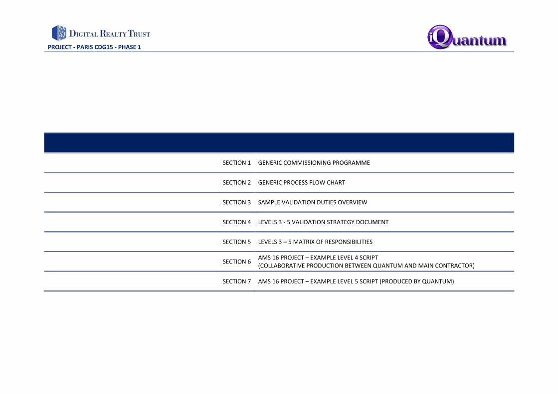
SECTION 1 GENERIC COMMISSIONING PROGRAMME
SECTION 2 GENERIC PROCESS FLOW CHART
SECTION 3 SAMPLE VALIDATION DUTIES OVERVIEW
SECTION 4 LEVELS 3 ‐ 5 VALIDATION STRATEGY DOCUMENT
SECTION 5 LEVELS 3 – 5 MATRIX OF RESPONSIBILITIES
SECTION 6 AMS 16 PROJECT – EXAMPLE LEVEL 4 SCRIPT (COLLABORATIVE PRODUCTION BETWEEN QUANTUM AND MAIN CONTRACTOR)
SECTION 7 AMS 16 PROJECT – EXAMPLE LEVEL 5 SCRIPT (PRODUCED BY QUANTUM)

PROJECT ‐ PARIS CDG15 ‐ PHASE 1
SECTION 1 GENERIC COMMISSIONING PROGRAMME

ID Task Name
1 LEVEL 1 - FACTORY ACCEPTANCE TESTING (FAT)
2 FAT Method Statements - Issue & Approval
3 FAT Witness Attendance (DLR / Consultant Engineers / Validation Engineers)
4 FAT Results / Report Issued to DLR
5 LEVEL 3 - COMMISSIONING OF M&E SERVICES / SITE ACCEPTANCE TESTING (SAT)
6 LEVEL 3 PROCESS DOCUMENTATION
7 Detailed Commissioning Plan: Issue and Approval Period
8 Detailed Commissioning Programme: Issue and Approval Period
9 Mechanical & Electrical L3 SAT Method Statements / Risk Assessments: Issue & Approval Period
10 ELECTRICAL SERVICES
11 MV Power Distribution System
12 MV Switchrooms - Construction Activities Complete and Switchrooms Handed Over to Electrical Installer
13 MV System - Electrical Installation Complete & Signed Off by Consultants
14 MV Switchboards - Panel Inspections Complete (including Cleanliness)
15 MV System - Testing, Energisation & Commissioning
16 MV System - Witnessing of Testing & Commissioning Results by Contractor's Commissioning Management Team
17 MV System - Inspection, Testing & Commissioning Documentation Issued to DLR / Validation Engineers
18 MV System - Commissioning Validation - DLR / Validation Engineer Witnessing
19 LV Power Distribution Systems
20 LV Switchrooms - Construction Activities Complete and Switchrooms Handed Over to Electrical Installer
21 LV System - Electrical Installation Complete & Signed Off by Consultants
22 LV Switchboards - Panel Inspections Complete (including Cleanliness)
23 LV System - Testing, Energisation & Commissioning
24 LV System - Witnessing of Testing & Commissioning Results by Contractor's Commissioning Management Team
25 LV System - Inspection, Testing & Commissioning Documentation Issued to DLR / Validation Engineers
26 LV System - Commissioning Validation - DLR / Validation Engineer Witnessing
27 Uninterruptable Power Supply (UPS) Systems
28 UPS Rooms - Construction Activities Complete and UPS Rooms Handed Over to Electrical Installer
29 UPS Systems - Electrical Installation Complete & Signed Off by Consultants
30 Battery Rooms - Construction Activities Complete and Handed Over
31 Battery Rooms - Electrical Installation Complete & Signed Off by Consultants
32 Temporary Load Banks & Interconnecting Cabling Installed for Commissioning
33 UPS Systems - Testing, Energisation & Commissioning
34 UPS Systems - Witnessing of Testing & Commissioning Results by Contractor's Commissioning Management Team
35 UPS Systems - Commissioning Validation - DLR / Validation Engineer Witnessing
36 UPS Systems - Inspection, Testing & Commissioning Documentation Issued to DLR / Validation Engineers
37 Standby Power Generators & Fuel Oil Supply System
38 Generator Rooms / Areas - Construction Activities Complete and Handed Over to Electrical Installer
39 Generators - Electrical Installation Complete & Signed Off by Consultants
40 Generator Switchboards - Panel Inspections Complete (including Cleanliness)
41 Fuel Supply System Rooms / Areas - Construction Activities Complete and Handed Over
42 Fuel Supply System - Installation Complete & Signed Off by Consultants
43 Temporary Load Banks & Interconnecting Cabling Installed for Commissioning
44 Generator System - Testing, Energisation & Commissioning
45 Generator System - Witnessing of Testing & Commissioning Results by Contractor's Commissioning Management Team
46 Generator System - Commissioning Validation - DLR / Validation Engineer Witnessing
47 Generator System - Inspection, Testing & Commissioning Documentation Issued to DLR / Validation Engineers
W-1 W1 W2 W3 W4 W5 W6 W7 W8 W9 W10 W11 W12 W13 W14 W15 W16M1 M2 M3 M4
SHELL BUILD / PBB & FIRST DATA HALL FIT-OUTCOMMISSIONING PROCESS GENERIC INDICATIVE PROGRAMME
Project: DLR GenericDate: Jan 2018
Page 1

ID Task Name
48 MECHANICAL SERVICES
49 Data Hall Air Conditioning System (IAC or DX + AHU)
50 Data Hall - Construction Activities Complete and Handed Over to Mechanical Installer
51 External AC Plant Area - Construction Activities Complete and Handed Over to Mechanical Installer
52 Data Hall AC - Mechanical Installation Complete & Signed Off by Consultants
53 Data Hall AC - Testing, Energisation & Commissioning
54 Data Hall AC - Witnessing of Testing & Commissioning Results by Contractor's Commissioning Management Team
55 Data Hall AC - Inspection, Testing & Commissioning Documentation Issued to DLR / Validation Engineers
56 Data Hall AC - Commissioning Validation - DLR / Validation Engineer Witnessing
57 UPS Rooms Air Conditioning Systems (CRAC DX / Supply & Extract Vent)
58 UPS Rooms - Construction Activities Complete and Handed Over to Mechanical Installer
59 UPS Rooms AC/Vent - Mechanical Installation Complete & Signed Off by Consultants
60 UPS Rooms AC/Vent - Testing, Energisation & Commissioning
61 UPS Rooms AC/Vent - Witnessing of Testing & Commissioning Results by Contractor's Commissioning Management Team
62 UPS Rooms AC/Vent - Inspection, Testing & Commissioning Documentation Issued to DLR / Validation Engineers"
63 UPS Rooms AC/Vent - Commissioning Validation - DLR / Validation Engineer Witnessing
64 Battery Rooms Air Conditioning Systems (DX AC & Extract Vent)
65 Battery Rooms - Construction Activities Complete and Handed Over to Mechanical Installer
66 Battery Rooms AC/Vent - Mechanical Installation Complete & Signed Off by Consultants
67 Battery Rooms AC/Vent - Testing, Energisation & Commissioning
68 Battery Rooms AC/Vent - Witnessing of Testing & Commissioning Results by Contractor's Commissioning Management Team
69 Battery Rooms AC/Vent - Inspection, Testing & Commissioning Documentation Issued to DLR / Validation Engineers"
70 Battery Rooms AC/Vent - Commissioning Validation - DLR / Validation Engineer Witnessing
71 POP Rooms Air Conditioning Systems (CRAC DX)
72 POP Rooms - Construction Activities Complete and Handed Over to Mechanical Installer
73 POP Rooms AC - Mechanical Installation Complete & Signed Off by Consultants
74 POP Rooms AC - Testing, Energisation & Commissioning
75 POP Rooms AC - Witnessing of Testing & Commissioning Results by Contractor's Commissioning Management Team
76 POP Rooms AC - Inspection, Testing & Commissioning Documentation Issued to DLR / Validation Engineers"
77 POP Rooms AC - Commissioning Validation - DLR / Validation Engineer Witnessing
78 MONITORING & CONTROLS SYSTEMS (DLR Network / BMS / DCIM / MV-LV PLC)
79 DLR Network Communications
80 Network Communication Installed, Tested & Operational
81 Building Management System (BMS)
82 BMS Installation Complete & Signed Off by Consultants
83 BMS Testing & Commissioning
84 MV System Interfacing (inc Metering)
85 LV System Interfacing (inc Metering)
86 UPS System Interfacing
87 Generators & Fuel System Interfacing
88 Data Hall Air Conditioning System Interfacing
89 UPS Room Air Conditioning Systems Interfacing
90 Battery Room Air Conditioning Systems Interfacing
91 POP Room Air Conditioning Systems Interfacing
92 Fire Detection & Alarm System Interfacing
93 Fire Suppression System (Water Mist) Interfacing
94 BMS Witnessing & Validation
95 Witnessing of BMS Commissioning Results by Contractor's Commissioning Management Team
96 BMS Commissioning Validation - DLR / Validation Engineer Witnessing
97 BMS - Commissioning Documentation Issued to DLR / Validation Engineers
W-1 W1 W2 W3 W4 W5 W6 W7 W8 W9 W10 W11 W12 W13 W14 W15 W16M1 M2 M3 M4
SHELL BUILD / PBB & FIRST DATA HALL FIT-OUTCOMMISSIONING PROCESS GENERIC INDICATIVE PROGRAMME
Project: DLR GenericDate: Jan 2018
Page 2

ID Task Name
98 Data Centre Infrastructure Management System (DCIM)
99 DCIM Testing & Integration with BMS/PLC
100 MV-LV Power Logic Control (PLC) System
101 MV/LV PLC - Testing & Commissioning
102 MV/LV PLC - Witnessing of Testing & Commissioning Results by Contractor's Commissioning Management Team
103 MV/LV PLC - Testing & Commissioning Documentation Issued to DLR / Validation Engineers
104 MV/LV PLC - Commissioning Validation - DLR / Validation Engineer Witnessing
105 FIRE DETECTION & ALARM SYSTEM (FAS)
106 Fire Alarm System - Installation Complete & Signed Off by Consultants
107 Fire Alarm System - Testing & Commissioning (inc Cause & Effect Test)
108 Fire Alarm System - Witnessing of Commissioning Results by Contractor's Commissioning Management Team
109 Fire Alarm System - Testing & Commissioning Documentation Issued to DLR / Validation Engineers"
110 Fire Alarm System - Commissioning Validation - DLR / Validation Engineer Witnessing
111 FIRE SUPPRESSION SYSTEM (WATER MIST)
112 Fire Suppression System - Installation Complete (inc Pressure Testing) & Signed Off by Consultants
113 Fire Suppression System - Testing & Commissioning
114 Fire Suppression System - Witnessing of Commissioning Results by Contractor's Commissioning Management Team
115 Fire Suppression System - Testing & Commissioning Documentation Issued to DLR / Validation Engineers"
116 Fire Suppression System - Commissioning Validation - DLR / Validation Engineer Witnessing
W-1 W1 W2 W3 W4 W5 W6 W7 W8 W9 W10 W11 W12 W13 W14 W15 W16M1 M2 M3 M4
SHELL BUILD / PBB & FIRST DATA HALL FIT-OUTCOMMISSIONING PROCESS GENERIC INDICATIVE PROGRAMME
Project: DLR GenericDate: Jan 2018
Page 3

ID Task Name
117 LEVEL 4 - INDIVIDUAL SYSTEM OPERATION VERIFICATION / INTEGRATED SYSTEMS TESTING
118 LEVEL 4A - INDIVIDUAL SYSTEM OPERATION VERIFICATION
119 MV System - Completion of All Commissioning & Issue of Associated Cx Documentation to DLR / Validation Engineers
120 LV Systems - Completion of All Commissioning & Issue of Associated Cx Documentation to DLR / Validation Engineers
121 UPS Systems - Completion of All Commissioning & Issue of Associated Cx Documentation to DLR / Validation Engineers
122 Generators & Fuel Oil Supply System - Completion of All Commissioning & Issue of Associated Cx Documentation to DLR / Validation Engineers
123 Data Hall Air Conditioning System - Completion of All Commissioning & Issue of Associated Cx Documentation to DLR / Validation Engineers
124 UPS Rooms Air Conditioning Systems - Completion of All Commissioning & Issue of Associated Cx Documentation to DLR / Validation Engineers
125 Battery Rooms Air Conditioning Systems - Completion of All Commissioning & Issue of Associated Cx Documentation to DLR / Validation Engineers
126 POP Room Air Conditioning Systems - Completion of All Commissioning & Issue of Associated Cx Documentation to DLR / Validation Engineers
127 BMS - Completion of All Commissioning & Issue of Associated Cx Documentation to DLR / Validation Engineers
128 Fire Alarm System - Completion of All Commissioning & Issue of Associated Cx Documentation to DLR / Validation Engineers
129 Fire Suppression System - Completion of All Commissioning & Issue of Associated Cx Documentation to DLR / Validation Engineers
130 MV/LV PLC - Completion of All Commissioning & Issue of Associated Cx Documentation to DLR / Validation Engineers
131 LEVEL 4B - INTEGRATED SYSTEMS TESTING VERIFICATION
132 Data Hall & Switchrooms DEEP CLEAN
133 Data Hall Heat Load Test
134 Final Commissioning of Data Hall Air Conditioning Systems (with Heat Load Available)
135 Busbar Thermo-graphic Imaging (at 100% IT Load)
136 Data Hall Mechanical Systems Resilience Testing (at 100% IT Load)
137 Data Hall Electrical Systems Resilience Testing (at 100% IT Load)
138 Fire Alarm System - Cause & Effect Test Demonstration to Local Authority
139 LEVEL 5 - INTEGRATED SYSTEMS OPERATION DEMONSTRATION
140 Data Hall Heat Load Test
141 Data Hall Mechanical Systems Resilience Testing (at 100% IT Load)
142 Data Hall Electrical Systems Resilience Testing (at 100% IT Load)
143 Data Hall & Switchrooms FINAL CLEAN
144 CLOSE OUT DOCUMENTATION - ISSUE TO DLR
145 Issue of Practical Completion Documentation and Health & Safety File
146 Issue of Final Approved Operating & Maintenance Manuals
147 Issue of Testing & Commissioning Results
148 Issue of As Built Drawings
149 Issue of 'Commissioning Complete' Letter to DLR (from Cx Validation Engineer)
150 Issue of Final 'IST Report' (by Cx Validation Engineer)
W-1 W1 W2 W3 W4 W5 W6 W7 W8 W9 W10 W11 W12 W13 W14 W15 W16M1 M2 M3 M4
SHELL BUILD / PBB & FIRST DATA HALL FIT-OUTCOMMISSIONING PROCESS GENERIC INDICATIVE PROGRAMME
Project: DLR GenericDate: Jan 2018
Page 4

PROJECT ‐ PARIS CDG15 ‐ PHASE 1
SECTION 2 GENERIC PROCESS FLOW CHART

GENERIC COMMISSIONING PROCESS FLOW CHART
LOCAL AUTHORITY
INTERFACES
Building Control / Fire
Officer Inspection &
Approvals
Multi-discipline
Method
Statements and
Procedures
LEVEL 5
L5 Electrical
Failure Resilience
Test
(at 100%
simulated IT Load)
L5 Mechanical
Failure Resilience
Test
(at 100%
simulated IT Load)
L5 Data Hall Heat
Load Test
(100% simulated
IT Load)
L3 Site
Acceptance Test
(SAT)
Multi-discipline
SAT Method
Statements
LEVEL 4
COMPLETE
L4 Electrical
Failure Resilience
Test
(at 100%
simulated IT Load)
Rework
RESULTS
VALIDATED
L4 Mechanical
Failure Resilience
Test
(at 100%
simulated IT Load)
L4 Data Hall Heat
Load Test
(100% simulated
IT Load)
Rework
L4 Site
Acceptance Test
(SAT)
Method
Statements
LEVEL 4
LEVEL 3
COMPLETE
Rework
RESULTS
VALIDATED
M&E SERVICES
MULTI-
DISCIPLINE
SITE
ACCEPTANCE
TESTING
(SAT)
Rework
Complete &
Approved
LEVEL 3
M&E Services
Installation
Inspections
Benchmark
Approvals
LEVEL 2
Rework
LEVEL 1
COMPLETE
Complete &
Approved
Multi-discipline
Programming
Factory
Acceptance
Testing (FAT)
LEVEL 1
Multi-discipline
Commissionability
Review
Multi-discipline
Commissioning
plan
START
PROCESS
LEVELS 1 TO 5
Rework
RESULTS
VALIDATED
Rework
L5 integrated
System Test (IST)
Procedural
Testing Document
PROJECT DOCUMENTATION:
1. Health & Safety File
2. Practical Completion Documentation
3. Approved Record Documentation
COMMISSIONING
COMPLETION LETTER
FORM 4.1
RESULTS
VALIDATED
L5 IST Report
LEVEL 5
COMPLETE
COMMISSIONING
PROCESS
LEVELS 1 TO 5
COMPLETE
PROJECT ‐ PARIS CDG15 ‐ PHASE 1
SECTION 3 SAMPLE VALIDATION DUTIES OVERVIEW

LEVEL 3 SITE ACCEPTANCE TESTING (SAT):
• Review of the Commissioning SAT method statements
• 25% Random sample Witnessing as follows:
o Power Distribution:
▪ HV Cable pressure tests
▪ HV & LV Switchboard SATs
▪ Transformer / RMU SATs
▪ Busbar ductor testing and thermal imaging
▪ Generator Load Bank Testing
▪ UPS Load Test and Battery Autonomy
o Cooling Systems:
▪ Data Hall IAC Unit SATs
▪ POP Room and UPS Room CRAC Unit SATs
▪ Data Hall AHU and Humidifier SAT
▪ Battery Room DX Unit SATs
o BMS:
▪ BMS Point to Graphic – as available (Switchboard Breakers, Meters, UPS, Generators, IAC’s, CRAC’s and DX Units)
o Fire Alarm / Fire Suppression:
▪ Fire Alarm Device Activation for confirmation of correct addressing to Fire Alarm Panel
▪ Fire Protection System – Zone Solenoid Valve Operation and interfaces to the Fire Alarm System

LEVEL 4 INTEGRATED SYSTEMS TEST:
• Production of the Level 4 IST document by Quantum in conjunction with the Contractor: (Stepped Heat Load / Mechanical Resilience Tests / Electrical Resilience Tests)
• Management / Control of Level 4 Testing activities (by Contractor)
• 100% Witnessing of the Level 4 IST (by Quantum)
• Generator / HV Control System SAT
• BMS Point to Graphic– to complete items that could not be done at Level 3 (Switchboard Breakers, Meters, UPS, Generators, IAC’s, CRAC’s and DX Units etc)
• Fire Alarm Cause & Effect Tests
LEVEL 5 INTEGRATED SYSTEMS OPERATION DEMONSTRATION:
• Production of the Level 5 IST document (by Quantum)
• Management / Control of Level 5 Testing activities (by Quantum)
• 100% Witnessing of the Level 5 IST (by Quantum)
• Production of Level 5 IST Report (by Quantum)

PROJECT ‐ PARIS CDG15 ‐ PHASE 1
SECTION 4 LEVELS 3 ‐ 5 VALIDATION STRATEGY DOCUMENT

QUANTUM AGREEMENT FRAMEWORK ANALYSIS DOCUMENT VALIDATION STRATEGY – LEVEL 3, 4 & 5
PRIMARY PROCESS LOGIC
• COMMISSIONING PLAN • PROGRAMMING • DOCUMENTATION
INTERFACES • OFF SITE TESTING • ESTABLISH MEETINGS
CONVENTION • RECORD DOCUMENTATION • PREPARE TRACKING TOOL
• FIELD COMPONENT VERIFICATION
• PROGRAMMING • RECORD DOCUMENTATION • PRODUCT STORAGE • CLIENT TRAINING • PERIODIC MEETINGS
• SYSTEM CONSTRUCTION VERIFICATION
• BENCHMARK TESTING • DOCUMENTATION
INTERFACES • PROGRAMMING • PERIODIC MEETINGS
• INDIVIDUAL SYSTEM OPERATION VALIDATION
• DOCUMENTATION • COMMISSIONING ISSUES
LOG • DAILY BREAKFAST &
EVENING MEETINGS • CLIENT TRAINING
• LEVEL 5 - PRE-REQUISITES • VALIDATE IST NARRATIVE
SCRIPT & PROCEDURAL CHECK LIST DOCUMENT
• INTEGRATED SYSTEMS
TESTING • COMMISSIONING ISSUES
LOG • PROGRAMMING • FINAL REPORT • CLIENT TRAINING

QUANTUM AGREEMENT FRAMEWORK ANALYSIS DOCUMENT VALIDATION STRATEGY – LEVEL 3, 4 & 5
PRIMARY PROCESS LOGIC
SYSTEM CONSTRUCTION - VALIDATION
Programme and co-ordinate all inspections
Arrange for attendance and witness
Document inspection and test results
Produce systems findings report
Attend meetings

QUANTUM AGREEMENT FRAMEWORK ANALYSIS DOCUMENT VALIDATION STRATEGY – LEVEL 3, 4 & 5
PRIMARY PROCESS LOGIC
BENCHMARK TESTING - VALIDATION
Validation of Installation Quality benchmark samples

QUANTUM AGREEMENT FRAMEWORK ANALYSIS DOCUMENT VALIDATION STRATEGY – LEVEL 3, 4 & 5
PRIMARY PROCESS LOGIC
PROGRAMMING - VALIDATION
Develop and police programme process
Maintain tracking mechanisms
Attend meetings

QUANTUM AGREEMENT FRAMEWORK ANALYSIS DOCUMENT VALIDATION STRATEGY – LEVEL 3, 4 & 5
PRIMARY PROCESS LOGIC
PERIODIC MEETINGS - VALIDATION
Chair and report on periodic meetings

QUANTUM AGREEMENT FRAMEWORK ANALYSIS DOCUMENT VALIDATION STRATEGY – LEVEL 3, 4 & 5
PRIMARY PROCESS LOGIC
INDIVIDUAL SYSTEM OPERATION - VALIDATION
Validate individual MEP systems completion
Confirm defined individual system operations and functionality to specified criteria
Witness all systems test results
Manage delivery of all associated test certification

QUANTUM AGREEMENT FRAMEWORK ANALYSIS DOCUMENT VALIDATION STRATEGY – LEVEL 3, 4 & 5
PRIMARY PROCESS LOGIC
DOCUMENTATION - VALIDATION
Establish availability of final approved O&M and As Built drawings prior to client training and level 5 works.

QUANTUM AGREEMENT FRAMEWORK ANALYSIS DOCUMENT VALIDATION STRATEGY – LEVEL 3, 4 & 5
PRIMARY PROCESS LOGIC
COMMISSIONING ISSUES LOG - VALIDATION
Produce comprehensive log incorporating all systems
Record any performance deficiencies witnessed during commissioning
Solution solve where appropriate and implement necessary measures

QUANTUM AGREEMENT FRAMEWORK ANALYSIS DOCUMENT VALIDATION STRATEGY – LEVEL 3, 4 & 5
PRIMARY PROCESS LOGIC
CLIENT TRAINING - VALIDATION
Confirm agreement to scope of client training plan
Confirm dates and attendee requirements
Ensure facilities and specialist information is provided for

QUANTUM AGREEMENT FRAMEWORK ANALYSIS DOCUMENT VALIDATION STRATEGY – LEVEL 3, 4 & 5
PRIMARY PROCESS LOGIC
LEVEL 5 - PRE-REQUISITE - VALIDATION
Confirm assembly of all appropriate document and certificates for all level 4 commissioning and acceptance testing prior to proceeding to level 5

QUANTUM AGREEMENT FRAMEWORK ANALYSIS DOCUMENT VALIDATION STRATEGY – LEVEL 3, 4 & 5
PRIMARY PROCESS LOGIC
VALIDATE IST NARRATIVE SCRIPT & PROCEDURAL CHECK LIST DOCUMENT - VALIDATION
Comment and agree Level 5 IST narrative script

QUANTUM AGREEMENT FRAMEWORK ANALYSIS DOCUMENT VALIDATION STRATEGY – LEVEL 3, 4 & 5
PRIMARY PROCESS LOGIC
INTEGRATED SYSTEMS TESTING - VALIDATION
Heat load test validation
IST Cause and effect validation
Black building test validation
Issue final report

QUANTUM AGREEMENT FRAMEWORK ANALYSIS DOCUMENT VALIDATION STRATEGY – LEVEL 3, 4 & 5
PRIMARY PROCESS LOGIC
COMMISSIONING ISSUES LOG - VALIDATION
Confirm any previously identified live issues resolved

QUANTUM AGREEMENT FRAMEWORK ANALYSIS DOCUMENT VALIDATION STRATEGY – LEVEL 3, 4 & 5
PRIMARY PROCESS LOGIC
PROGRAMMING - VALIDATION
Close out all programmed activities

QUANTUM AGREEMENT FRAMEWORK ANALYSIS DOCUMENT VALIDATION STRATEGY – LEVEL 3, 4 & 5
PRIMARY PROCESS LOGIC
FINAL REPORT - VALIDATION
Executive summary
Design descriptions / parameters
Summary performance report
Level 1, 2 and 3 documentation
FAT documentation
SAT documentation
Level 5 IST documentation
Electrical and BMS trend reports

QUANTUM AGREEMENT FRAMEWORK ANALYSIS DOCUMENT VALIDATION STRATEGY – LEVEL 3, 4 & 5
PRIMARY PROCESS LOGIC
CLIENT TRAINING - VALIDATION
Confirm agreement to scope of client training plan
Confirm dates and attendee requirements
Ensure facilities and specialist information is provided for
Manage delivery of client training in conjunction with the Main Contractor and DLR operations team

PROJECT ‐ PARIS CDG15 ‐ PHASE 1
SECTION 5 LEVELS 3 – 5 MATRIX OF RESPONSIBILITIES

QUANTUM AGREEMENT FRAMEWORK ANALYSIS DOCUMENT KEY PARTIES RESPONSIBILITIES INTERFACE MATRIX – LEVELS 3, 4 & 5
LEVEL 3 - ACTIVITY HEADING MAIN CONTRACTOR MC
COMMISSIONING MANAGER - CM (APPOINTED BY MAIN CONTRACTOR)
M&E CONTRACTOR’S COMMISSIONING SPECIALIST - CS
VALIDATION ENGINEER
SYSTEM CONSTRUCTION VERIFICATION Programme and co-ordinate all inspections Liaise with CM Manage Process Not Applicable Validate Production,
review/comment Arrange for attendance and witness Liaise with CM Witness Not Applicable Validate Production,
review/comment Document inspection and test results Liaise with CM Document inspections Not Applicable Validate Production,
review/comment Produce systems findings report Liaise with CM Produce Findings Report Not Applicable Validate Production,
review/comment Attend meetings Liaise with CM Co-ordinate meetings Not Applicable Attend meetings BENCHMARK TESTING Validation of Installation Quality benchmark samples Liaise with CM Co-ordinate Process Not Applicable Validate Production, review/ DOCUMENTATION INTERFACES Review procedures and method statements Liaise with CM Execute Execute in conjunction with
CM Validate Production, review/comment
Agree scope and production timescales in collaboration with the Main Contractor
Liaise with CM Execute in conjunction with MC
Execute in conjunction with CM
Validate Production, review/comment
Produce comprehensive commissioning and test sheets templates for use by the Main Contractors commissioning team
Liaise with CM Execute in conjunction with CS Execute in conjunction with CM
Validate Production, review/comment
Manage, co-ordinate and validate all test certificates and specified inspection criteria
Liaise with CM Execute in conjunction with CS Execute in conjunction with CM
Validate Production, review/comment
Track O&M manuals and As Built drawing production programme Liaise with CM Manage Process Not Applicable Validate Production Manage draft issue submission and review process Liaise with CM Manage Process Not Applicable Validate Production Attend meetings Attend as necessary Chair Meetings Attend as necessary Attend Meetings PROGRAMMING Develop and police programme process Liaise with CM Execute Not Applicable Validate Production Maintain tracking mechanisms Liaise with CM Execute Not Applicable Validate Production Attend meetings Attend as necessary Chair Meetings Attend as necessary Attend Meetings PERIODIC MEETINGS Chair and report on periodic meetings Attend as necessary Chair Meetings Attend as necessary Attend Meetings

QUANTUM AGREEMENT FRAMEWORK ANALYSIS DOCUMENT KEY PARTIES RESPONSIBILITIES INTERFACE MATRIX – LEVELS 3, 4 & 5
LEVEL 4 - ACTIVITY HEADING MAIN CONTRACTOR MC
COMMISSIONING MANAGER - CM (APPOINTED BY MAIN CONTRACTOR)
M&E CONTRACTOR’S COMMISSIONING SPECIALIST - CS
VALIDATION ENGINEER
INDIVIDUAL SYSTEM OPERATION VALIDATION
Validate individual MEP systems completion Liaise with CM Direct Process In conjunction
with CS Co-ordinate witness with VE
Execute works to be witnessed liaise with CM
Validate Test results produce Independent findings report
Confirm defined individual system operations and functionality to specified criteria
Liaise with CM Direct Process In conjunction with CS Co-ordinate witness with VE
Execute works to be witnessed liaise with CM
Validate Test results produce Independent findings report
Witness all systems test results Liaise with CM Direct Process In conjunction
with CS Co-ordinate witness with VE
Execute works to be witnessed liaise with CM
Validate Test results produce Independent findings report
Manage delivery of all associated test certification Liaise with CM Co-ordinate delivery in
conjunction with VE Deliver documentation In conjunction with CM
Validate Test results produce Independent findings report
DOCUMENTATION Establish availability of final approved O&M and As Built drawings prior to client training and level 5 works.
Confirm In conjunction with CM
Manage delivery Process Confirm all Test Results IN place In conjunction with CM
Validate Test results produce Independent findings report
COMMISSIONING ISSUES LOG Produce comprehensive log incorporating all systems Liaise with CM Produce Log Liaise with VE Co-ordinate with CM Validate Production produce
Independent findings report Record any performance deficiencies witnessed during commissioning Liaise with CM Record and Liaise with VE Co-ordinate with CM Validate Production produce
Independent findings report Solution solve where appropriate and implement necessary measures Liaise with CM Co-ordinate with VE, agree
measures Co-ordinate with CM Validate Production produce
Independent findings report DAILY BREAKFAST & EVENING MEETINGS Daily breakfast & evening meetings Liaise with CM Attend meetings Attend meetings Attend meetings CLIENT TRAINING Confirm agreement to scope of client training plan Liaise with CM Confirm
delivery Manage Process Liaise with VE Attend as necessary Validate Process Liaise with CM
Attend Training Confirm dates and attendee requirements Liaise with CM Manage Process Liaise with VE Not applicable Validate Process Liaise with CM
Attend Training Ensure facilities and specialist information is provided for Liaise with CM Manage Process Liaise with VE Not applicable Validate Process Liaise with CM
Attend Training

QUANTUM AGREEMENT FRAMEWORK ANALYSIS DOCUMENT KEY PARTIES RESPONSIBILITIES INTERFACE MATRIX – LEVELS 3, 4 & 5
LEVEL 5 - ACTIVITY HEADING MAIN CONTRACTOR MC
COMMISSIONING MANAGER - CM (APPOINTED BY MAIN CONTRACTOR)
M&E CONTRACTOR’S COMMISSIONING SPECIALIST - CS
VALIDATION ENGINEER
Confirm assembly of all appropriate document and certificates for all level 4 commissioning and acceptance testing prior to proceeding to level 5
Confirm with CM Execute Assembly Liaise with CM Validate Delivery In conjunction with CM
VALIDATE IST NARRATIVE SCRIPT & PROCEDURAL CHECK LIST DOCUMENT Comment and agree Level 5 IST narrative script Liaise with CM Produce In conjunction with
CM Not Applicable Produce In conjunction with
CM INTEGRATED SYSTEMS TESTING Heat load test validation Liaise with CM Manage Process Support as necessary Validate Process,
review/comment IST Cause and effect validation Liaise with CM Manage Process Support as necessary Validate Process,
review/comment Black building test validation Liaise with CM Manage Process Support as necessary Validate Process
review/comment Issue final report Liaise with CM Produce Final Report Support as necessary Produce Independent findings
Report COMMISSIONING ISSUES LOG Confirm any previously identified live issues resolved Liaise with CM Confirm resolution In
conjunction with VE Support as necessary Confirm resolution In
conjunction with CM PROGRAMMING Close out all programmed activities Confirm with CM Confirm Completeness Support as necessary Validate Completeness FINAL REPORT Executive summary Liaise with VE as necessary Liaise with VE as necessary Liaise with VE as necessary Produce Independent Report Design descriptions / parameters Liaise with VE as necessary Liaise with VE as necessary Liaise with VE as necessary Produce Independent Report Summary performance report Liaise with VE as necessary Liaise with VE as necessary Liaise with VE as necessary Produce Independent Report Level 1, 2 and 3 documentation Liaise with VE as necessary Liaise with VE as necessary Liaise with VE as necessary Produce Independent Report FAT documentation Liaise with VE as necessary Liaise with VE as necessary Liaise with VE as necessary Produce Independent Report SAT documentation Liaise with VE as necessary Liaise with VE as necessary Liaise with VE as necessary Produce Independent Report Level 5 IST documentation Liaise with VE as necessary Liaise with VE as necessary Liaise with VE as necessary Produce Independent Report Electrical and BMS trend reports Liaise with VE as necessary Liaise with VE as necessary Liaise with VE as necessary Produce Independent Report CLIENT TRAINING Confirm agreement to scope of client training plan Liaise with CM Confirm
delivery Manage Process Liaise with VE Attend as necessary Validate Process Liaise with CM
Attend Training Confirm dates and attendee requirements Liaise with CM Manage Process Liaise with VE Not applicable Validate Process Liaise with CM
Attend Training Ensure facilities and specialist information is provided for Liaise with CM Manage Process Liaise with VE Not applicable Validate Process Liaise with CM
Attend Training Manage delivery of client training with MC and DLR Operations Team Liaise with CM Confirm
delivery Manage Process Liaise with VE Attend as necessary Validate Process Liaise with CM
Attend Training

PROJECT ‐ PARIS CDG15 ‐ PHASE 1
SECTION 6 AMS 16 PROJECT – EXAMPLE LEVEL 4 SCRIPT (COLLABORATIVE PRODUCTION BETWEEN QUANTUM AND MAIN CONTRACTOR)
PROJECT: AMS16 DATA CENTRE – DATA HALLS S230 & S240 LEVEL 4: INTEGRATED SYSTEMS TESTING
Level 4 Integrated Systems Testing Rev 01 Draft PROJECT: AMS16 Data Centre - Data Halls S230 & S240 1 20th September 2019
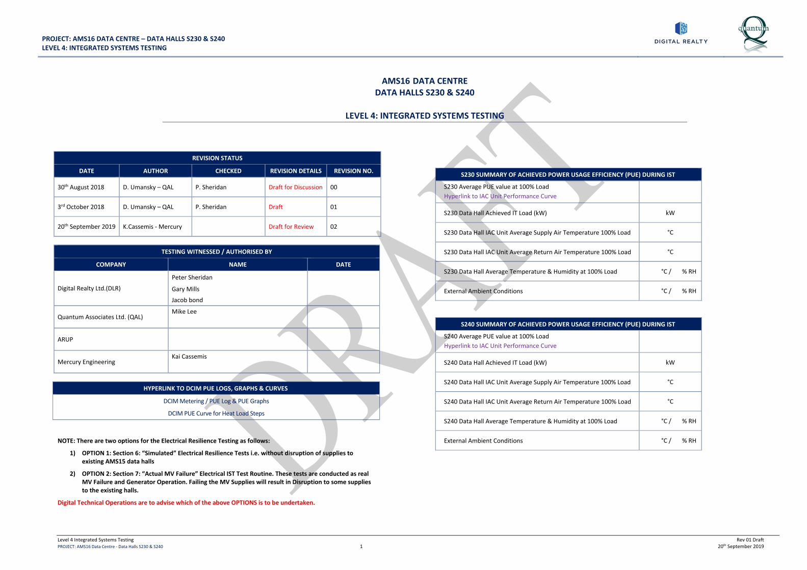
AMS16 DATA CENTRE DATA HALLS S230 & S240
LEVEL 4: INTEGRATED SYSTEMS TESTING
REVISION STATUS
DATE AUTHOR CHECKED REVISION DETAILS REVISION NO.
30th August 2018 D. Umansky – QAL P. Sheridan Draft for Discussion 00
3rd October 2018 D. Umansky – QAL P. Sheridan Draft 01
20th September 2019 K.Cassemis - Mercury Draft for Review 02
TESTING WITNESSED / AUTHORISED BY
COMPANY NAME DATE
Digital Realty Ltd.(DLR)
Peter Sheridan
Gary Mills
Jacob bond
Quantum Associates Ltd. (QAL) Mike Lee
ARUP
Mercury Engineering Kai Cassemis
HYPERLINK TO DCIM PUE LOGS, GRAPHS & CURVES
DCIM Metering / PUE Log & PUE Graphs
DCIM PUE Curve for Heat Load Steps
NOTE: There are two options for the Electrical Resilience Testing as follows:
1) OPTION 1: Section 6: “Simulated” Electrical Resilience Tests i.e. without disruption of supplies to existing AMS15 data halls
2) OPTION 2: Section 7: “Actual MV Failure” Electrical IST Test Routine. These tests are conducted as real MV Failure and Generator Operation. Failing the MV Supplies will result in Disruption to some supplies to the existing halls.
Digital Technical Operations are to advise which of the above OPTIONS is to be undertaken.
S230 SUMMARY OF ACHIEVED POWER USAGE EFFICIENCY (PUE) DURING IST
S230 Average PUE value at 100% Load Hyperlink to IAC Unit Performance Curve
S230 Data Hall Achieved IT Load (kW) kW
S230 Data Hall IAC Unit Average Supply Air Temperature 100% Load °C
S230 Data Hall IAC Unit Average Return Air Temperature 100% Load °C
S230 Data Hall Average Temperature & Humidity at 100% Load °C / % RH
External Ambient Conditions °C / % RH
S240 SUMMARY OF ACHIEVED POWER USAGE EFFICIENCY (PUE) DURING IST
S240 Average PUE value at 100% Load Hyperlink to IAC Unit Performance Curve
S240 Data Hall Achieved IT Load (kW) kW
S240 Data Hall IAC Unit Average Supply Air Temperature 100% Load °C
S240 Data Hall IAC Unit Average Return Air Temperature 100% Load °C
S240 Data Hall Average Temperature & Humidity at 100% Load °C / % RH
External Ambient Conditions °C / % RH

PROJECT: AMS16 DATA CENTRE – DATA HALLS S230 & S240 LEVEL 4: INTEGRATED SYSTEMS TESTING
Level 4 Integrated Systems Testing Rev 01 Draft PROJECT: AMS16 Data Centre - Data Halls S230 & S240 2 20th September 2019
INDEX 1.0 INTRODUCTION ................................................................................................................................................ 3
BASIS OF THE ELECTRICAL SERVICES AND POWER SYSTEMS DESIGN ............................................................................................3
BASIS OF THE MECHANICAL SERVICES DESIGN ......................................................................................................................3
TESTING OBJECTIVES .....................................................................................................................................................3
2.0 PRE-REQUISITES TO LEVEL 4 TESTING PROGRAMME COMMENCEMENT ............................................. 4 PRE-START BRIEFING SCHEDULE .......................................................................................................................................4
PRE-START CHECKLIST / HEALTH & SAFETY .........................................................................................................................4
PREREQUISITES TO COMMENCEMENT OF IST .......................................................................................................................5
SPECIFIC REQUIREMENTS – CONFIRMED DAILY PRIOR TO TESTS ................................................................................................6
3.0 TEAM RESPONSIBILITIES / LEVEL 4 TESTING LOGISTICS ........................................................................ 7 4.0 TEST PROCEDURES ........................................................................................................................................ 8
TEST OBJECTIVES & TEST ACCEPTANCE CRITERIA: .................................................................................................................8
CONDITIONS TO BE MAINTAINED WITHIN SERVER ROOMS, ANCILLARY AREAS AND ASSOCIATED PLANT: ................................................8
5.0 STEPPED HEAT LOAD TEST AND MECHANICAL RESILIENCE TEST PROCEDURES (L4 IST DAY 1) ... 9 TEST NO. 01 – PRE-START CHECK (L4 IST DAY 1) ................................................................................................................9
TEST NO. 02 – DATA HALL NORMALISATION PERIOD (L4 IST DAY 1) ........................................................................................9
TEST NO. 03 – LOAD DATA HALL TO 15% (L4 IST DAY 1) .....................................................................................................9
TEST NO. 04 – LOAD DATA HALL TO 25% (L4 IST DAY 1) ................................................................................................... 10
TEST NO. 05 – LOAD DATA HALL TO 50% (L4 IST DAY 1) ................................................................................................... 10
TEST NO. 06 – LOAD DATA HALL TO 75% (L4 IST DAY 1) ................................................................................................... 10
TEST NO. 07 – LOAD DATA HALL TO 100% (L4 IST DAY 1) .................................................................................................. 11
TEST NO. 08 – FAIL ALL IAC UNITS INDIVIDUALLY IN EACH DATA HALL (L4 IST DAY 1) ............................................................... 11
TEST NO. 09 – FAIL NETWORK BETWEEN IAC UNITS 04 & 05 IN EACH DATA HALL (L4 IST DAY 1) ................................................ 11
TEST NO. 10 – FAIL NETWORK BETWEEN IAC UNITS 01 & 02 IN EACH DATA HALL (L4 IST DAY 1) ................................................ 12
TEST NO. 11 – ISOLATE ONE SIDE OF THE MAKE-UP WATER RING MAIN TO THE IAC UNITS IN EACH DATA HALL (L4 IST DAY 1) ........... 12
TEST NO. 12 – FAIL AHU ON IAC-02 IN EACH DATA HALL (L4 IST DAY 1) ............................................................................... 13
TEST NO. 13 – FAIL AHU ON IAC-08 IN EACH DATA HALL (L4 IST DAY 1) ............................................................................... 13
TEST NO. 14 – STEP DOWN LOAD FROM 100% TO 0% (L4 IST DAY 1)................................................................................... 13
6.0 “SIMULATED” ELECTRICAL RESILIENCE TOLERANCE TESTING PROCEDURES AT 100% LOAD (L4 IST DAY 2) ....................................................................................................................................................... 14 COMMENTARY ON “SIMULATED” ELECTRICAL IST TEST ROUTINE ............................................................................................ 14
TEST NO. 01 – PRE-START CHECK (L4 IST DAY 2) .............................................................................................................. 15
TEST NO. 02 – DATA HALL NORMALISATION PERIOD (L4 IST DAY 2) ...................................................................................... 15
TEST NO. 03– LOAD DATA HALL TO 100% (L4 IST DAY 2) .................................................................................................. 15
TEST NO. 04 – SIMULATE FAILURE & REINSTATEMENT OF LV-A SUPPLY (L4 IST DAY 2) .............................................................. 16
TEST NO. 05 – SIMULATE FAILURE & REINSTATEMENT OF LV-B SUPPLY (L4 IST DAY 2) .............................................................. 16
TEST NO. 06 – SIMULATE FAILURE & REINSTATEMENT OF LV-C SUPPLY (L4 IST DAY 2) .............................................................. 17
TEST NO. 07 – SIMULATE FAILURE & REINSTATEMENT OF LV-D SUPPLY (L4 IST DAY 2) .............................................................. 17
TEST NO. 08 – SIMULATE FAILURE & REINSTATEMENT OF LV-E SUPPLY (L4 IST DAY 2) .............................................................. 18
TEST NO. 09 – SIMULATE FAILURE & REINSTATEMENT OF LV-F SUPPLY (L4 IST DAY 2) ............................................................. 18
TEST NO. 10 – SIMULATE FAILURE & REINSTATEMENT OF MV A SUPPLY (L4 IST DAY 2) ............................................................ 19
TEST NO. 11 – SIMULATE FAILURE & REINSTATEMENT OF MV B SUPPLY (L4 IST DAY 2) ............................................................ 19
TEST NO. 12 – SIMULATE FAILURE & REINSTATEMENT OF MV A AND B SUPPLIES (L4 IST DAY 2) ................................................. 20
TEST NO. 13 – STEP DOWN LOAD FROM 100% TO 0% (L4 IST DAY 2) .................................................................................. 20
7.0 “ACTUAL MV FAILURE” ELECTRICAL RESILIENCE TOLERANCE TESTING PROCEDURES AT 100% LOAD (L4 IST DAY 2) ..................................................................................................................................... 21 COMMENTARY ON “ACTUAL MV FAILURE” ELECTRICAL IST TEST ROUTINE .............................................................................. 21
TEST NO. 01 – PRE-START CHECK (L4 IST DAY 2) ............................................................................................................. 21
TEST NO. 02 – DATA HALL NORMALISATION PERIOD (L4 IST DAY 2) ..................................................................................... 21
TEST NO. 03– LOAD DATA HALL TO 100% (L4 IST DAY 2) ................................................................................................. 21
TEST NO. 04 – SIMULATE FAILURE & REINSTATEMENT OF LV-A SUPPLY (L4 IST DAY 2) ............................................................. 22
TEST NO. 05 – SIMULATE FAILURE & REINSTATEMENT OF LV-B SUPPLY (L4 IST DAY 2) ............................................................. 22
TEST NO. 06 – SIMULATE FAILURE & REINSTATEMENT OF LV-C SUPPLY (L4 IST DAY 2) ............................................................. 23
TEST NO. 07 – SIMULATE FAILURE & REINSTATEMENT OF LV-D SUPPLY (L4 IST DAY 2) ............................................................. 23
TEST NO. 08 – SIMULATE FAILURE & REINSTATEMENT OF LV-E SUPPLY (L4 IST DAY 2) ............................................................. 24
TEST NO. 09 – SIMULATE FAILURE & REINSTATEMENT OF LV-F SUPPLY (L4 IST DAY 2) ............................................................. 24
TEST NO. 10 – FAILURE & REINSTATEMENT OF MV A SUPPLY (L4 IST DAY 2) ......................................................................... 25
TEST NO. 11 – FAILURE & REINSTATEMENT OF MV A SUPPLY (L4 IST DAY 2) ......................................................................... 25
TEST NO. 12 – FAILURE & REINSTATEMENT OF MV B SUPPLY (L4 IST DAY 2) .......................................................................... 26
TEST NO. 13 – FAILURE & REINSTATEMENT OF MV B SUPPLY (L4 IST DAY 2) .......................................................................... 26
TEST NO. 14 – FAILURE & REINSTATEMENT OF MV A AND B SUPPLIES WITH OPEN TRANSITION RESTORATION (L4 IST DAY 2) ............. 27
TEST NO. 15 – FAILURE & REINSTATEMENT OF MV A AND B SUPPLIES WITH OPEN TRANSITION RESTORATION (L4 IST DAY 2) ............. 27
TEST NO. 16 – FAILURE & REINSTATEMENT OF MV A AND B SUPPLIES WITH CLOSED TRANSITION RESTORATION (L4 IST DAY 2) .......... 28
TEST NO. 17 – FAILURE & REINSTATEMENT OF MV A AND B SUPPLIES WITH CLOSED TRANSITION RESTORATION (L4 IST DAY 2) .......... 28
TEST NO. 18 – STEP DOWN LOAD FROM 100% TO 0% (L4 IST DAY 2) .................................................................................. 28
8.0 ADDITIONAL TESTS REQUIRED BY DIGITAL REALTY TECHNICAL OPERATIONS TEAM (L4 IST DAY 2) .......................................................................................................................................................................... 29 TEST NO. 01 – IAC UNIT HUMIDIFIER RUN ON 100% LOAD FOR 8 HOUR DURATION (L4 IST DAY 2) ............................................. 29
TEST NO. 02 – IAC UNIT PROCESS COOLING WATER VOLUMETRIC FLOW RATE TEST ON 100% LOAD (L4 IST DAY 2) ........................ 29
TEST NO. 03 - IAC UNITS POWER LOSS RECOVERY TIME ON 100% LOAD (L4 IST DAY 2) ........................................................... 29
TEST NO. 04 - UPS COMMISSIONING WHEN ON LOAD – DEMONSTRATION OF MAINTENANCE ON THE MODULES L4 IST DAY 2) ............ 30

PROJECT: AMS16 DATA CENTRE – DATA HALLS S230 & S240 LEVEL 4: INTEGRATED SYSTEMS TESTING
Level 4 Integrated Systems Testing Rev 01 Draft PROJECT: AMS16 Data Centre - Data Halls S230 & S240 3 20th September 2019
1.0 INTRODUCTION
The Project is the construction of two new Data Halls (S230 & S240) in the Data Centre, including support areas as follows:
• S230: Data Hall Rated at 2000 kW maximum design capacity
• S240: Data Hall Rated at 3000 kW maximum design capacity
• Six number electrical switchrooms each with UPS for N+1 resilience
• 4 number 2.75 MVA/2.0 MW/10.5kV Generators
• S230: 7 number Indirect Adiabatic Cooling Units (IAC) providing N+1 resilience
• S240: 10 number Indirect Adiabatic Cooling Units (IAC) providing N+1 resilience
• Mechanical plant areas for support systems
Basis of the Electrical Services and Power Systems Design
The site comprises of a two 20/10.5kV substation distributing 10.5 kV to the MV Switchboards. The main MV switchgear further distributes 10.5 kV supplies around site to Data Hall switch rooms.
The site is supported by 4 number MV Generators.
The Data Hall is supported by 6 number. LV Switchboards (S230/S240-SB-LV-A, S230/S240-SB-LV-B, S230/S240-LV-C, S230/S240-LV-D, S230/S240-LV-E and S230/S240-LV-F).
Each LV Switchboard is supplied by a packaged substation consisting of externally mounted 10.5kV/400V transformer & Ring Main Unit. Each LV Switchboard is provided with a UPS and ancillary plant.
Each substation is fed via the sites MV distribution system. The switchrooms serve the Data Halls via overhead bus bars which drop to raised floor level on entry to the Data Halls.
Critical mechanical equipment is provided with A and B feeds with integral automatic changeover where required.
Basis of the Mechanical Services Design
Data Hall S230 is cooled by an arrangement of 7 Number IAC Units arranged to provide N+1 resilience.
Data Hall S240 is cooled by an arrangement of 10 Number IAC Units arranged to provide N+1 resilience.
A make-up water supply system is provided to feed the IAC units from underground storage tanks, break tanks and booster pump sets with micron filtration equipment.
Data Halls S230 & S240 are each provided with 2 number Air Handling Units (½N / ½N) each with integral steam humidifier and external DX condenser units for the cooling coil. These provide fresh air to the Data Halls and maintain a positive pressure in the Hall relative to the access corridor. These also provide for humidification and de-humidification of the Data Halls. Supply air is ducted to each Data Hall via connections to the discharge ductwork from two of the IAC Units
Each of the UPS / LV Switch rooms are provided with 2 number DX CRAC Units (N+1) for cooling
Each of the UPS Battery Rooms are provided with 2 number Split DX Cooling Units (N+1) and supplementation extract system
Testing Objectives
The principal tests are as follows:
1. To demonstrate the Data Hall Mechanical and Electrical Systems working in a simulated environment.
2. Room Validation Tests to prove the performance of the installed cooling systems serving the Data Hall areas under full load conditions.
3. IAC unit performance load tests and all associated plant and equipment that is critical to the environmental conditions within the Data Hall.
4. Tests with all systems healthy under full load, in fault and under maintenance scenarios.
5. Electrical Validation testing to prove the performance of the Main Electrical Distribution System.
6. UPS performance and resilience.
7. To provide an operational PUE Graph throughout the heat load test
Note: It is not the intention to repeat any of the commissioning /certification tests that must be completed as a prerequisite to these tests. The principal aim is to assess the overall impact of systems operation on the fully loaded facility.
The purpose of this document is to detail the procedures to be undertaken, confirm responsibilities and prerequisites to the commencement of the tests – and finally to review requirements for final pro-forma record documentation.
The testing will be undertaken in the following sequence:
1. Various Stepped Heat Load Test to prove IAC Unit Temperature and Pressure Control (L4 IST DAY 1)
o Simulated heat load to 100% (incremental load steps)
2. Electrical and Mechanical Resilience Tests at simulated 100% Heat Load (L4 IST DAY 2)
o Simulated 100% heat load

PROJECT: AMS16 DATA CENTRE – DATA HALLS S230 & S240 LEVEL 4: INTEGRATED SYSTEMS TESTING
Level 4 Integrated Systems Testing Rev 01 Draft PROJECT: AMS16 Data Centre - Data Halls S230 & S240 4 20th September 2019
2.0 PRE-REQUISITES TO LEVEL 4 TESTING PROGRAMME COMMENCEMENT
Pre-Start Briefing Schedule Co-ordination briefings to be held on the following basis up to the start of Level 4 Integrated Systems Testing. Mercury Engineering will chair the briefings, at which the pre-start checklist will be reviewed.
Item Description Attendees Date Completed
1 Level 4 Pre-Start Briefing a) General review of pre-start checklist confirming all
health & safety / general logistics issues covered. b) Confirm start dates for tests and review of briefing
dates accordingly. c) Confirm approval of this document.
All personnel included in tests
2 Level 4 Daily Briefings a) Debriefing held following each set of tests each
morning. b) Review of forthcoming tests and responsibilities. c) Sign off sheet to be incorporated into test method
statements.
All personnel included in tests
Pre-Start Checklist / Health & Safety
Item Description Action Date Cleared
1 Set up Control Room
a) Networked BMS Head-End
b) All head-ends to be provided with colour printer, and sufficient paper
c) Software back-ups to be provided for BMS
d) Resilient power supplies for all the above plus additional spare supplies for additional laptops for IST controller & for BMS head-end
e) Room to contain a set of As-fitted schematics for reference.
f) Radio base station – provide 10no digital radios - (Spare radio batteries and chargers) to be located in control room. – with sufficient power supply
g) Sufficient desk space for all above PCs and equipment. Seating for up to 8 within control room
Mercury
2 Agree Briefing/Base Area
Mercury to provide necessary seating / layout table Mercury
3 Personnel confirmed by each organisation
a) Team responsibilities and locations agreed (Section 3).
b) Contact details included in schedule
c) Contractors to confirm personnel
d) All personnel inducted into site
Mercury
4 Radio Communications
Provide 10no. digital radios for IST
(1 no radio required per team plus spares).
Mercury
5 Provide necessary Health & Safety signage
a) escape route designation
b) key room identification (i.e. switchrooms, plantrooms, control room etc)
c) plant labelling
Mercury

PROJECT: AMS16 DATA CENTRE – DATA HALLS S230 & S240 LEVEL 4: INTEGRATED SYSTEMS TESTING
Level 4 Integrated Systems Testing Rev 01 Draft PROJECT: AMS16 Data Centre - Data Halls S230 & S240 5 20th September 2019
Prerequisites to Commencement of IST
Item Description Action Cleared
1 All Electrical systems complete / signed-off and Test Certification issued to DLR Mercury
2 All MV and Generator Control Sequences proven, witnessed / signed-off and Test Certification issued to DLR Mercury
3 All Mechanical systems complete / signed-off and Test Certification issued to DLR Mercury
4 BMS & PME commissioning complete and signed off and Test Certification issued to DLR Mercury
5 All Fire detection & Protection systems complete & demonstrated to Local Building Control Authority and Test Certification issued to DLR Mercury
6 Secured access controlled doors commissioning complete Mercury
7 Load banks: heaters installed to agreed configuration in the Data Hall. Mercury
8 Temperature logging devices to be installed at agreed locations. Mercury
PROJECT: AMS16 DATA CENTRE – DATA HALLS S230 & S240 LEVEL 4: INTEGRATED SYSTEMS TESTING
Level 4 Integrated Systems Testing Rev 01 Draft PROJECT: AMS16 Data Centre - Data Halls S230 & S240 6 20th September 2019
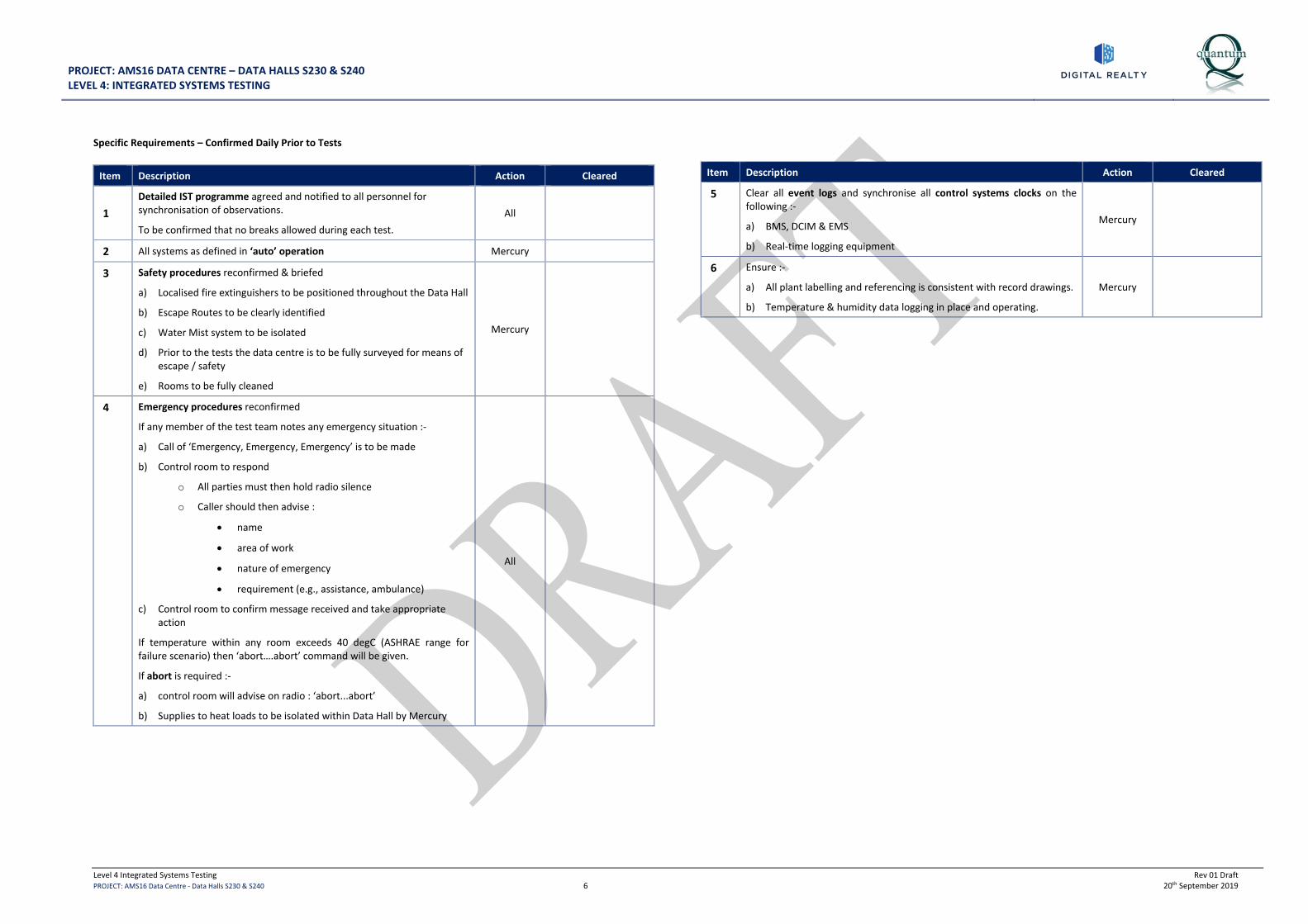
Specific Requirements – Confirmed Daily Prior to Tests
Item Description Action Cleared
1 Detailed IST programme agreed and notified to all personnel for synchronisation of observations.
To be confirmed that no breaks allowed during each test. All
2 All systems as defined in ‘auto’ operation Mercury
3 Safety procedures reconfirmed & briefed
a) Localised fire extinguishers to be positioned throughout the Data Hall
b) Escape Routes to be clearly identified
c) Water Mist system to be isolated
d) Prior to the tests the data centre is to be fully surveyed for means of escape / safety
e) Rooms to be fully cleaned
Mercury
4 Emergency procedures reconfirmed
If any member of the test team notes any emergency situation :-
a) Call of ‘Emergency, Emergency, Emergency’ is to be made
b) Control room to respond
o All parties must then hold radio silence
o Caller should then advise :
• name
• area of work
• nature of emergency
• requirement (e.g., assistance, ambulance)
c) Control room to confirm message received and take appropriate action
If temperature within any room exceeds 40 degC (ASHRAE range for failure scenario) then ‘abort….abort’ command will be given.
If abort is required :-
a) control room will advise on radio : ‘abort...abort’
b) Supplies to heat loads to be isolated within Data Hall by Mercury
All
Item Description Action Cleared
5 Clear all event logs and synchronise all control systems clocks on the following :-
a) BMS, DCIM & EMS
b) Real-time logging equipment
Mercury
6 Ensure :-
a) All plant labelling and referencing is consistent with record drawings.
b) Temperature & humidity data logging in place and operating.
Mercury

PROJECT: AMS16 DATA CENTRE – DATA HALLS S230 & S240 LEVEL 4: INTEGRATED SYSTEMS TESTING
Level 4 Integrated Systems Testing Rev 01 Draft PROJECT: AMS16 Data Centre - Data Halls S230 & S240 7 20th September 2019
3.0 TEAM RESPONSIBILITIES / LEVEL 4 TESTING LOGISTICS
Party Responsibility / Outline Location Personnel Names
Mercury
Overall package contractor co-ordination. Site safety co-ordination.
Provision of radio communications. Provision of temperature & humidity data loggers.
Provision of Hot Aisle containment simulation. Provision of Heaters/Load Banks.
Attendance at control room and representative locations around site.
Kai Cassemis
Thomas Mclaughlin
Fady Ziada
Mercury Co-ordination & overall control of Level 4 demonstration witnessing, review of testing and commissioning report results from package contractors. Attendance at control room and representative locations around site. Kai Cassemis
Mercury
Set-up and management of load banks (heaters).
Overall co-ordination of electrical services elements - including failure of supplies as detailed within test procedures. AP required for LV switchrooms.
Attendance required throughout at representative locations in Data Hall (for load management) and LV switchrooms.
Thomas Mclaughlin
Leo Quiggley
Kai Cassemis
Mercury
Review / reporting on mechanical systems performance through heat load test during IST,
Attendance in mechanical plantrooms during power resilience tests.
Review / reporting on mechanical plant status.
Attendance at external Plant (IAC Units & Make-Up Water Supply System)
Kai Cassemis
Rory Owens
Mercury Mechanical commissioning checks Kai Cassemis
Quantum Associates Witness & validation of Level 4 IST Testing
Attendance at control room and representative locations around site. Mike Lee
Digital Realty
Witness / review of testing.
Overall review of testing and general advice / comment as programme progresses.
Attendance at control room and representative locations around site.
Peter Sheridan
Gary Mills
Jacob bond
UPS Contractor Observe & reporting on UPS status. Attendance at UPS. Gert Boot
Generators Contractor Observe & reporting on Generator status. Attendance at Generators. Randy Wouten
IAC Contractor Observe & reporting on IAC unit status. Attendance at Data Hall IAC units. James Duffy
BMS Contractor Observe & reporting on BMS & mechanical systems performance through heat load test & IST. Marcos Perez

PROJECT: AMS16 DATA CENTRE – DATA HALLS S230 & S240 LEVEL 4: INTEGRATED SYSTEMS TESTING
Level 4 Integrated Systems Testing Rev 01 Draft PROJECT: AMS16 Data Centre - Data Halls S230 & S240 8 20th September 2019
4.0 TEST PROCEDURES
Test Objectives & Test Acceptance Criteria: 1 To verify the performance of the installed mechanical systems serving the Data Halls S230, S240 and Ancillary Areas
under full load conditions including selected failure scenarios. 2 To verify the electrical fault resilience under normal operating conditions, including selected failure scenarios.
Conditions to be maintained within server rooms, ancillary areas and associated plant:
Design parameters for the services within the Data Halls S230 & S240
Theoretical PUE at 100% Load To be advised (Annualised) S230
To be advised (Annualised) S240
External Design Conditions
Summer:
Dry Bulb: 34.6˚C (extreme annual condition for n = 20 years)
Wet Bulb: 24.5°C (extreme maximum wet bulb)
Winter:
Summer and winter design conditions are the same
Data Hall Temperature 24 ± 1.5 ˚C – Target Supply Temperature
Data Hall Relative Humidity Range 5.5°C DP – 60% RH & 15°C DP
UPS Battery Rooms 20 ± 2 ˚C
UPS / LV Switchrooms 20 ± 2 ˚C
Data Hall Pressurisation AHU Supply Air Temperature/Humidity Set Points 24 ˚C / 30% to 70% RH
S230 Data Hall – Max. Electrical IT Load Up to 2000 kW
S240 Data Hall – Max. Electrical IT Load Up to 3000 kW

PROJECT: AMS16 DATA CENTRE – DATA HALLS S230 & S440 LEVEL 4: INTEGRATED SYSTEMS TESTING
Level 4 Integrated Systems Testing Rev 01 Draft PROJECT: AMS16 Data Centre - Data Halls S230 & S240 9 20th September 2019
5.0 STEPPED HEAT LOAD TEST AND MECHANICAL RESILIENCE TEST PROCEDURES (L4 IST DAY 1)
Test No. 01 – Pre-Start Check (L4 IST Day 1)
ITEM DETAILS DATE START TIME
FINISH TIME
HYPERLINKS TO ASSOCIATED DOCUMENTATION S230 RESULTS / OBSERVATIONS S240 RESULTS/ OBSERVATIONS
1.
Ensure all systems are operational under automatic control and clear of any alarms prior to proceeding with any tests.
All plant and systems verified operational enabling test continuation.
N/A
Expected Result:
All plant verified as operational under automatic control.
No fault alarms on BMS (except IAC low Return Air Temp)
Expected Result:
All plant verified as operational under automatic control.
No fault alarms on BMS (except IAC low Return Air Temp)
Test No. 02 – Data Hall Normalisation Period (L4 IST Day 1)
ITEM DETAILS DATE START TIME
FINISH TIME
HYPERLINKS TO ASSOCIATED DOCUMENTATION S230 RESULTS/ OBSERVATIONS S240 RESULTS/ OBSERVATIONS
1.
All systems operational with no load.
Ensure room is stable for a period of time before taking load and temperature measurements. Proceed only once measurements are complete.
BMS Graphics Screen shots
BMS Logs (Data Hall Temperature, Humidity & IAC’s)
DCIM Metering / PUE Logs & PUE Graphs
DCIM Graphics Screen shots
PME Graphics Screen shots
Data Hall Temp/Humid Data Logger Results
Total Utility Load: kW
Data Hall IT Load: 0 kW (0%)
No Heat Load applied.
Total Utility Load: kW
Data Hall IT Load: 0 kW (0%)
No Heat Load applied.
Test No. 03 – Load Data Hall to 15% (L4 IST Day 1)
ITEM DETAILS DATE START TIME
FINISH TIME
HYPERLINKS TO ASSOCIATED DOCUMENTATION S230 RESULTS/ OBSERVATIONS S240 RESULTS/ OBSERVATIONS
1.
Apply 15% load (300 kW) equally distributed in Data Hall S230.
Ensure Data Hall is stable for a period of time before taking load and temperature measurements. Proceed only once measurements are complete. Apply 15% load (450 kW) equally distributed in Data Hall S240.
Ensure Data Hall is stable for a period of time before taking load and temperature measurements. Proceed only once measurements are complete.
BMS Graphics Screen shots
BMS Logs (Data Hall Temperature, Humidity & IAC’s)
DCIM Metering / PUE Logs & PUE Graphs
DCIM Graphics Screen shots
PME Graphics Screen shots
Data Hall Temp/Humid Data Logger Results
Total Utility Load: kW
S230 Data Hall IT Load: kW (…..%)
S230 PUE:
Data Hall Average Space Conditions: ……°C / …….% RH
IAC Unit Average Supply Air Temperature: …….°C
IAC Unit Average Return Air Temperature: ……..°C
External Ambient Conditions: …….°C / ……..% RH
Total Utility Load: kW
S240 Data Hall IT Load: kW (…..%)
S240 PUE:
Data Hall Average Space Conditions: ……°C / …….% RH
IAC Unit Average Supply Air Temperature: …….°C
IAC Unit Average Return Air Temperature: ……..°C
External Ambient Conditions: …….°C / ……..% RH

PROJECT: AMS16 DATA CENTRE – DATA HALLS S230 & S440 LEVEL 4: INTEGRATED SYSTEMS TESTING
Level 4 Integrated Systems Testing Rev 01 Draft PROJECT: AMS16 Data Centre - Data Halls S230 & S240 10 20th September 2019
Test No. 04 – Load Data Hall to 25% (L4 IST Day 1)
ITEM DETAILS DATE START TIME
FINISH TIME
HYPERLINKS TO ASSOCIATED DOCUMENTATION S230 RESULTS/ OBSERVATIONS S240 RESULTS/ OBSERVATIONS
1.
Apply 25% load (500 kW) equally distributed in Data Hall S230.
Ensure Data Hall is stable for a period of time before taking load and temperature measurements. Proceed only once measurements are complete. Apply 25% load (750 kW) equally distributed in Data Hall S240.
Ensure Data Hall is stable for a period of time before taking load and temperature measurements. Proceed only once measurements are complete.
BMS Graphics Screen shots
BMS Logs (Data Hall Temperature, Humidity & IAC’s)
DCIM Metering / PUE Logs & PUE Graphs
DCIM Graphics Screen shots
PME Graphics Screen shots
Data Hall Temp/Humid Data Logger Results
Total Utility Load: kW
S230 Data Hall IT Load: kW (…..%)
S230 PUE:
Data Hall Average Space Conditions: ……°C / …….% RH
IAC Unit Average Supply Air Temperature: …….°C
IAC Unit Average Return Air Temperature: ……..°C
External Ambient Conditions: …….°C / ……..% RH
Total Utility Load: kW
S240 Data Hall IT Load: kW (…..%)
S240 PUE:
Data Hall Average Space Conditions: ……°C / …….% RH
IAC Unit Average Supply Air Temperature: …….°C
IAC Unit Average Return Air Temperature: ……..°C
External Ambient Conditions: …….°C / ……..% RH
Test No. 05 – Load Data Hall to 50% (L4 IST Day 1)
ITEM DETAILS DATE START TIME
FINISH TIME
HYPERLINKS TO ASSOCIATED DOCUMENTATION S230 RESULTS/ OBSERVATIONS S240 RESULTS/ OBSERVATIONS
1.
Apply 50% load (1000 kW) equally distributed in Data Hall S230.
Ensure Data Hall is stable for a period of time before taking load and temperature measurements. Proceed only once measurements are complete. Apply 50% load (1500 kW) equally distributed in Data Hall S240.
Ensure Data Hall is stable for a period of time before taking load and temperature measurements. Proceed only once measurements are complete.
BMS Graphics Screen shots
BMS Logs (Data Hall Temperature, Humidity & IAC’s)
DCIM Metering / PUE Logs & PUE Graphs
DCIM Graphics Screen shots
PME Graphics Screen shots
Data Hall Temp/Humid Data Logger Results
Total Utility Load: kW
S230 Data Hall IT Load: kW (…..%)
S230 PUE:
Data Hall Average Space Conditions: ……°C / …….% RH
IAC Unit Average Supply Air Temperature: …….°C
IAC Unit Average Return Air Temperature: ……..°C
External Ambient Conditions: …….°C / ……..% RH
Total Utility Load: kW
S240 Data Hall IT Load: kW (…..%)
S240 PUE:
Data Hall Average Space Conditions: ……°C / …….% RH
IAC Unit Average Supply Air Temperature: …….°C
IAC Unit Average Return Air Temperature: ……..°C
External Ambient Conditions: …….°C / ……..% RH
Test No. 06 – Load Data Hall to 75% (L4 IST Day 1)
ITEM DETAILS DATE START TIME
FINISH TIME
HYPERLINKS TO ASSOCIATED DOCUMENTATION S130 RESULTS/ OBSERVATIONS S140 RESULTS/ OBSERVATIONS
1.
Apply 75% load (1500 kW) equally distributed in Data Hall S230.
Ensure Data Hall is stable for a period of time before taking load and temperature measurements. Proceed only once measurements are complete. Apply 75% load (2250 kW) equally distributed in Data Hall S240.
Ensure Data Hall is stable for a period of time before taking load and temperature measurements. Proceed only once measurements are complete.
BMS Graphics Screen shots
BMS Logs (Data Hall Temperature, Humidity & IAC’s)
DCIM Metering / PUE Logs & PUE Graphs
DCIM Graphics Screen shots
PME Graphics Screen shots
Data Hall Temp/Humid Data Logger Results
Total Utility Load: kW
S230 Data Hall IT Load: kW (…..%)
S230 PUE:
Data Hall Average Space Conditions: ……°C / …….% RH
IAC Unit Average Supply Air Temperature: …….°C
IAC Unit Average Return Air Temperature: ……..°C
External Ambient Conditions: …….°C / ……..% RH
Total Utility Load: kW
S240 Data Hall IT Load: kW (…..%)
S240 PUE:
Data Hall Average Space Conditions: ……°C / …….% RH
IAC Unit Average Supply Air Temperature: …….°C
IAC Unit Average Return Air Temperature: ……..°C
External Ambient Conditions: …….°C / ……..% RH

PROJECT: AMS16 DATA CENTRE – DATA HALLS S230 & S440 LEVEL 4: INTEGRATED SYSTEMS TESTING
Level 4 Integrated Systems Testing Rev 01 Draft PROJECT: AMS16 Data Centre - Data Halls S230 & S240 11 20th September 2019
Test No. 07 – Load Data Hall to 100% (L4 IST Day 1)
ITEM DETAILS DATE START TIME
FINISH TIME
HYPERLINKS TO ASSOCIATED DOCUMENTATION S230 RESULTS/ OBSERVATIONS S240 RESULTS/ OBSERVATIONS
1.
Apply 100% load (2000 kW) equally distributed in Data Hall S230.
Ensure Data Hall is stable for a period of time before taking load and temperature measurements. Proceed only once measurements are complete. Apply 100% load (3000 kW) equally distributed in Data Hall S240.
Ensure Data Hall is stable for a period of time before taking load and temperature measurements. Proceed only once measurements are complete.
BMS Graphics Screen shots
BMS Logs (Data Hall Temperature, Humidity & IAC’s)
DCIM Metering / PUE Logs & PUE Graphs
DCIM Graphics Screen shots
PME Graphics Screen shots
Data Hall Temp/Humid Data Logger Results
Total Utility Load: kW
S230 Data Hall IT Load: kW (…..%)
S230 PUE:
Data Hall Average Space Conditions: ……°C / …….% RH
IAC Unit Average Supply Air Temperature: …….°C
IAC Unit Average Return Air Temperature: ……..°C
External Ambient Conditions: …….°C / ……..% RH
Total Utility Load: kW
S240 Data Hall IT Load: kW (…..%)
S240 PUE:
Data Hall Average Space Conditions: ……°C / …….% RH
IAC Unit Average Supply Air Temperature: …….°C
IAC Unit Average Return Air Temperature: ……..°C
External Ambient Conditions: …….°C / ……..% RH
Test No. 08 – Fail All IAC Units Individually in each Data Hall (L4 IST Day 1)
ITEM DETAILS DATE START TIME
FINISH TIME
HYPERLINKS TO ASSOCIATED DOCUMENTATION S230 RESULTS/ OBSERVATIONS S240 RESULTS/ OBSERVATIONS
1.
With 100% load equally distributed (S230 2000 kW / S240 3000 kW).
Fail S230-IAC-01 to 07 individually and ensure space conditions remain stable.
Fail S240-IAC-01 to 10 individually and ensure space conditions remain stable.
Remaining IAC units will see an increase as the load migrates away from the failed unit. Proceed to next test only when the data hall temperatures have settled.
Reinstate IAC Units back to operation
Ensure room stable before proceeding to failure tests
BMS Graphics Screen shots
BMS Logs (Data Hall Temperature, Humidity & IAC’s)
DCIM Metering / PUE Logs & PUE Graphs
DCIM Graphics Screen shots
PME Graphics Screen shots
Data Hall Temp/Humid Data Logger Results
Total Utility Load: kW
S230 Data Hall IT Load: kW (…..%)
S230 PUE:
Data Hall Average Space Conditions: ……°C / …….% RH
IAC Unit Average Supply Air Temperature: …….°C
IAC Unit Average Return Air Temperature: ……..°C
External Ambient Conditions: …….°C / ……..% RH
Total Utility Load: kW
S240 Data Hall IT Load: kW (…..%)
S240 PUE:
Data Hall Average Space Conditions: ……°C / …….% RH
IAC Unit Average Supply Air Temperature: …….°C
IAC Unit Average Return Air Temperature: ……..°C
External Ambient Conditions: …….°C / ……..% RH
Test No. 09 – Fail Network between IAC Units 04 & 05 in each Data Hall (L4 IST Day 1)
ITEM DETAILS DATE START TIME
FINISH TIME
HYPERLINKS TO ASSOCIATED DOCUMENTATION S230 RESULTS/ OBSERVATIONS S240 RESULTS/ OBSERVATIONS
1.
With 100% load equally distributed (S230 2000 kW / S240 3000 kW).
Fail Network between S230-IAC-04 & 05 and ensure space conditions remain stable.
Fail Network between S240-IAC-04 & 05 and ensure space conditions remain stable.
Observe effect upon hall conditions and operating IACs. Proceed to next test only when the data hall temperature and IAC unit loadings have settled.
Reinstate network back to normal operation
BMS Graphics Screen shots
BMS Logs (Data Hall Temperature, Humidity & IAC’s)
DCIM Metering / PUE Logs & PUE Graphs
DCIM Graphics Screen shots
PME Graphics Screen shots
Data Hall Temp/Humid Data Logger Results
Total Utility Load: kW
S230 Data Hall IT Load: kW (…..%)
S230 PUE:
Data Hall Average Space Conditions: ……°C / …….% RH
IAC Unit Average Supply Air Temperature: …….°C
IAC Unit Average Return Air Temperature: ……..°C
External Ambient Conditions: …….°C / ……..% RH
Total Utility Load: kW
S240 Data Hall IT Load: kW (…..%)
S240 PUE:
Data Hall Average Space Conditions: ……°C / …….% RH
IAC Unit Average Supply Air Temperature: …….°C
IAC Unit Average Return Air Temperature: ……..°C
External Ambient Conditions: …….°C / ……..% RH

PROJECT: AMS16 DATA CENTRE – DATA HALLS S230 & S440 LEVEL 4: INTEGRATED SYSTEMS TESTING
Level 4 Integrated Systems Testing Rev 01 Draft PROJECT: AMS16 Data Centre - Data Halls S230 & S240 12 20th September 2019
Ensure room stable before proceeding to failure tests
Test No. 10 – Fail Network between IAC Units 01 & 02 in each Data Hall (L4 IST Day 1)
ITEM DETAILS DATE START TIME
FINISH TIME
HYPERLINKS TO ASSOCIATED DOCUMENTATION S230 RESULTS/ OBSERVATIONS S240 RESULTS/ OBSERVATIONS
1.
With 100% load equally distributed (S230 2000 kW / S240 3000 kW).
Fail Network between S230-IAC-01 & 02 and ensure space conditions remain stable.
Fail Network between S240-IAC-01 & 02 and ensure space conditions remain stable.
Observe effect upon hall conditions and operating IACs. Proceed to next test only when the data hall temperature and IAC unit loadings have settled.
Reinstate network back to normal operation
Ensure room stable before proceeding to failure tests
BMS Graphics Screen shots
BMS Logs (Data Hall Temperature, Humidity & IAC’s)
DCIM Metering / PUE Logs & PUE Graphs
DCIM Graphics Screen shots
PME Graphics Screen shots
Data Hall Temp/Humid Data Logger Results
Total Utility Load: kW
S230 Data Hall IT Load: kW (…..%)
S230 PUE:
Data Hall Average Space Conditions: ……°C / …….% RH
IAC Unit Average Supply Air Temperature: …….°C
IAC Unit Average Return Air Temperature: ……..°C
External Ambient Conditions: …….°C / ……..% RH
Total Utility Load: kW
S240 Data Hall IT Load: kW (…..%)
S240 PUE:
Data Hall Average Space Conditions: ……°C / …….% RH
IAC Unit Average Supply Air Temperature: …….°C
IAC Unit Average Return Air Temperature: ……..°C
External Ambient Conditions: …….°C / ……..% RH
Test No. 11 – Isolate one side of the Make-Up Water Ring Main to the IAC Units in each Data Hall (L4 IST Day 1)
ITEM DETAILS DATE START TIME
FINISH TIME
HYPERLINKS TO ASSOCIATED DOCUMENTATION S230 RESULTS/ OBSERVATIONS S240 RESULTS/ OBSERVATIONS
1.
With 100% load equally distributed (S230 2000 kW / S240 3000 kW).
Set 100% Adiabatic Spray Condition to 2 number IAC Units in each Data Hall (S230-IAC-01, S230-IAC-02, S240-IAC-01 and S240-IAC-02)
Isolate one side of the make-up Water Ring Main to the S230 IAC Units.
Isolate one side of the make-up Water Ring Main to the S240 IAC Units.
Ensure that IAC Adiabatic Spray is Operating after ring main isolation
Reinstate Water Ring Main back to normal operation
Ensure room stable before proceeding to failure tests
BMS Graphics Screen shots
BMS Logs (Data Hall Temperature, Humidity & IAC’s)
DCIM Metering / PUE Logs & PUE Graphs
DCIM Graphics Screen shots
PME Graphics Screen shots
Data Hall Temp/Humid Data Logger Results
Total Utility Load: kW
S230 Data Hall IT Load: kW (…..%)
S230 PUE:
Data Hall Average Space Conditions: ……°C / …….% RH
IAC Unit Average Supply Air Temperature: …….°C
IAC Unit Average Return Air Temperature: ……..°C
External Ambient Conditions: …….°C / ……..% RH
Adiabatic Spray Operation Confirmed at both IAC’s
Total Utility Load: kW
S240 Data Hall IT Load: kW (…..%)
S240 PUE:
Data Hall Average Space Conditions: ……°C / …….% RH
IAC Unit Average Supply Air Temperature: …….°C
IAC Unit Average Return Air Temperature: ……..°C
External Ambient Conditions: …….°C / ……..% RH
Adiabatic Spray Operation Confirmed at both IAC’s

PROJECT: AMS16 DATA CENTRE – DATA HALLS S230 & S440 LEVEL 4: INTEGRATED SYSTEMS TESTING
Level 4 Integrated Systems Testing Rev 01 Draft PROJECT: AMS16 Data Centre - Data Halls S230 & S240 13 20th September 2019
Test No. 12 – Fail AHU on IAC-02 in each Data Hall (L4 IST Day 1)
ITEM DETAILS DATE START TIME
FINISH TIME
HYPERLINKS TO ASSOCIATED DOCUMENTATION S230 RESULTS/ OBSERVATIONS S240 RESULTS/ OBSERVATIONS
1.
With 100% load equally distributed (S230 2000 kW / S240 3000 kW).
Fail the AHU on S230-IAC-02 and ensure space conditions remain stable.
Fail the AHU on S240-IAC-02 and ensure space conditions remain stable.
Observe effect upon Data Hall conditions and operation of AHU on S230-IAC-08 & S240-IAC-08. Proceed to next test only when the data hall temperature and IAC unit loadings have settled.
Reinstate AHU’s back to normal operation
Ensure room stable before proceeding to failure tests
BMS Graphics Screen shots
BMS Logs (Data Hall Temperature, Humidity & IAC’s)
DCIM Metering / PUE Logs & PUE Graphs
DCIM Graphics Screen shots
PME Graphics Screen shots
Data Hall Temp/Humid Data Logger Results
Total Utility Load: kW
S230 Data Hall IT Load: kW (…..%)
S230 PUE:
Data Hall Average Space Conditions: ……°C / …….% RH
IAC Unit Average Supply Air Temperature: …….°C
IAC Unit Average Return Air Temperature: ……..°C
External Ambient Conditions: …….°C / ……..% RH
Total Utility Load: kW
S240 Data Hall IT Load: kW (…..%)
S240 PUE:
Data Hall Average Space Conditions: ……°C / …….% RH
IAC Unit Average Supply Air Temperature: …….°C
IAC Unit Average Return Air Temperature: ……..°C
External Ambient Conditions: …….°C / ……..% RH
Test No. 13 – Fail AHU on IAC-08 in each Data Hall (L4 IST Day 1)
ITEM DETAILS DATE START TIME
FINISH TIME
HYPERLINKS TO ASSOCIATED DOCUMENTATION S230 RESULTS/ OBSERVATIONS S240 RESULTS/ OBSERVATIONS
1.
With 100% load equally distributed (S230 2000 kW / S240 3000 kW).
Fail the AHU on S230-IAC-08 and ensure space conditions remain stable.
Fail the AHU on S240-IAC-08 and ensure space conditions remain stable.
Observe effect upon Data Hall conditions and operation of AHU on S230-IAC-02 & S240-IAC-02. Proceed to next test only when the data hall temperature and IAC unit loadings have settled.
Reinstate AHU’s back to normal operation
Ensure room stable before proceeding to failure tests
BMS Graphics Screen shots
BMS Logs (Data Hall Temperature, Humidity & IAC’s)
DCIM Metering / PUE Logs & PUE Graphs
DCIM Graphics Screen shots
PME Graphics Screen shots
Data Hall Temp/Humid Data Logger Results
Total Utility Load: kW
S230 Data Hall IT Load: kW (…..%)
S230 PUE:
Data Hall Average Space Conditions: ……°C / …….% RH
IAC Unit Average Supply Air Temperature: …….°C
IAC Unit Average Return Air Temperature: ……..°C
External Ambient Conditions: …….°C / ……..% RH
Total Utility Load: kW
S240 Data Hall IT Load: kW (…..%)
S240 PUE:
Data Hall Average Space Conditions: ……°C / …….% RH
IAC Unit Average Supply Air Temperature: …….°C
IAC Unit Average Return Air Temperature: ……..°C
External Ambient Conditions: …….°C / ……..% RH
Test No. 14 – Step Down Load From 100% to 0% (L4 IST Day 1)
ITEM DETAILS DATE START TIME
FINISH TIME
HYPERLINKS TO ASSOCIATED DOCUMENTATION S130 RESULTS/ OBSERVATIONS S140 RESULTS/ OBSERVATIONS
1. Step Down Load from 100% to 0% in stepped decreases in Data Halls S230 & S240
Implement Fire Watch for 1 hour N/A N/A N/A

PROJECT: AMS16 DATA CENTRE – DATA HALLS S230 & S440 LEVEL 4: INTEGRATED SYSTEMS TESTING
Level 4 Integrated Systems Testing Rev 01 Draft PROJECT: AMS16 Data Centre - Data Halls S230 & S240 14 20th September 2019
6.0 “SIMULATED” ELECTRICAL RESILIENCE TOLERANCE TESTING PROCEDURES AT 100% LOAD (L4 IST DAY 2)
Commentary on “Simulated” Electrical IST Test Routine Electrical failure can occur from a number of causes:-
1) One LV Board could be lost due to: • LV Incomer opening on fault or isolation due to maintenance • Loss of transformer • Ring Main Feeder opening on fault or PLC maloperation
This will not result in generator start as the loss of mains sensing is via the MV Boards although IAC units will changeover to alternate supplies after the set failure time resulting in a short partial loss of cooling which should be compensated by the remaining units.
Isolating the IACs instead of the entire boards ensures that the UPS batteries are not discharged unnecessarily.
These tests will have no effect upon the operation of the existing halls.
2) It is possible that an MV ring could be lost due to: • Unit failure • Incorrect operation of one of the ring switches • MV Breaker opening on fault or PLC maloperation
This will not result in generator start as the loss of mains sensing is via the MV Boards although supplies to a number of LV Boards will be lost and IAC units will changeover to alternate supplies (where available) after the set failure time resulting in a short partial loss of cooling which should be compensated by the remaining units.
This failure would have the same effect as the failure of one LV board so is covered by the test series as in 1) above.
3) Either one or both of the MV Supplies could be lost due to: • Equipment failure • Network operational problems • Loss of main supplies
This will result in generator operation whereby supplies should be restored to the site MV network in the order of 20 seconds although closure of the transformers is staged to avoid overloads caused by transformer inrush currents. In order to simulate the worst possible situation a supply restoration from generators is simulated at 30 seconds and the staging is increased to 10 seconds.
These tests are conducted as simulations as opening the MV Breakers on the Supply boards will result in Disruption of some supplies to the existing halls.
NOTE: It is assumed that all Generator Functional Testing will have been completed as part of Mercury’s Level 4 Testing.

PROJECT: AMS16 DATA CENTRE – DATA HALLS S230 & S440 LEVEL 4: INTEGRATED SYSTEMS TESTING
Level 4 Integrated Systems Testing Rev 01 Draft PROJECT: AMS16 Data Centre - Data Halls S230 & S240 15 20th September 2019
Test No. 01 – Pre-Start Check (L4 IST Day 2)
ITEM DETAILS DATE START TIME
FINISH TIME
HYPERLINKS TO ASSOCIATED DOCUMENTATION S230 RESULTS / OBSERVATIONS S240 RESULTS/ OBSERVATIONS
1.
Ensure all systems are operational under automatic control and clear of any alarms prior to proceeding with any tests.
All plant and systems verified operational enabling test continuation.
N/A
Expected Result:
All plant verified as operational under automatic control.
No fault alarms on BMS (except IAC low Return Air Temp)
Expected Result:
All plant verified as operational under automatic control.
No fault alarms on BMS (except IAC low Return Air Temp)
Test No. 02 – Data Hall Normalisation Period (L4 IST Day 2)
ITEM DETAILS DATE START TIME
FINISH TIME
HYPERLINKS TO ASSOCIATED DOCUMENTATION S230 RESULTS/ OBSERVATIONS S240 RESULTS/ OBSERVATIONS
1.
All systems operational with no load.
Ensure room is stable for a period of time before taking load and temperature measurements. Proceed only once measurements are complete.
BMS Graphics Screen shots
BMS Logs (Data Hall Temperature, Humidity & IAC’s)
DCIM Metering / PUE Logs & PUE Graphs
DCIM Graphics Screen shots
PME Graphics Screen shots
Data Hall Temp/Humid Data Logger Results
Total Utility Load: kW
Data Hall IT Load: 0 kW (0%)
No Heat Load applied.
Total Utility Load: kW
Data Hall IT Load: 0 kW (0%)
No Heat Load applied.
Test No. 03– Load Data Hall to 100% (L4 IST Day 2)
ITEM DETAILS DATE START TIME
FINISH TIME HYPERLINKS TO ASSOCIATED DOCUMENTATION S230 – S240 RESULTS / OBSERVATIONS
1.
Apply 100% load (2000 kW) equally distributed in Data Hall S230.
Ensure Data Hall is stable for a period of time before taking load and temperature measurements. Proceed to failure tests only once measurements are complete. Apply 100% load (3000 kW) equally distributed in Data Hall S240.
Ensure Data Hall is stable for a period of time before taking load and temperature measurements.
Proceed to failure tests only once measurements are complete.
BMS Graphics Screen shots
BMS Logs (Data Hall Temperature, Humidity & IAC’s)
DCIM Metering / PUE Logs & PUE Graphs
DCIM Graphics Screen shots
PME Graphics Screen shots & Logs
Data Hall Temp/Humid Data Logger Results
LV Board HMI Graphic Screen shots
UPS Output Meters: MV Feeder Meters
A ………….kW Ring A ………….kW
B ………….kW Ring B ………….kW
C ………….kW Ring C ………….kW
D ………….kW Ring D ………….kW
E ………….kW Ring E ………….kW
F ………….kW Ring F ………….kW
Total load:……….kW Total: ………….kW
External Ambient Conditions: …….°C / ……..% RH
S230: Average Data Hall Conditions: 0C / % RH
S230 PUE:
S240: Average Data Hall Conditions: 0C / % RH
S240 PUE:

PROJECT: AMS16 DATA CENTRE – DATA HALLS S230 & S440 LEVEL 4: INTEGRATED SYSTEMS TESTING
Level 4 Integrated Systems Testing Rev 01 Draft PROJECT: AMS16 Data Centre - Data Halls S230 & S240 16 20th September 2019
Test No. 04 – Simulate Failure & Reinstatement of LV-A Supply (L4 IST Day 2)
ITEM DETAILS DATE START TIME
FINISH TIME HYPERLINKS TO ASSOCIATED DOCUMENTATION S230 – S240 RESULTS / OBSERVATIONS
1.
Simulate failure of LV-A Supply by opening breakers to S230-IAC-01 and S240-IAC-01
Ensure that IACs S230-01 and S240-01 change to alternate supplies.
There should be no manual intervention during anytime during the test.
Proceed to next test only when the data hall temperature & humidity have settled.
Re-instate supplies to IAC Units by closing breakers to S230-IAC-01 and S240-IAC-01
Ensure that IACs S230-01 and S240-01 change to preferred supplies
There should be no manual intervention during anytime during the test.
Proceed to next test only when the data hall temperature & humidity have settled.
BMS Graphics Screen shots
BMS Logs (Data Hall Temperature, Humidity & IAC’s)
DCIM Metering / PUE Logs & PUE Graphs
DCIM Graphics Screen shots
PME Graphics Screen shots & Logs
Data Hall Temp/Humid Data Logger Results
LV Board HMI Graphic Screen shots
UPS Output Meters: MV Feeder Meters
A ………….kW Ring A ………….kW
B ………….kW Ring B ………….kW
C ………….kW Ring C ………….kW
D ………….kW Ring D ………….kW
E ………….kW Ring E ………….kW
F ………….kW Ring F ………….kW
Total load:……….kW Total: ………….kW
External Ambient Conditions: …….°C / ……..% RH
S230: Average Data Hall Conditions: 0C / % RH
S230 PUE:
S240: Average Data Hall Conditions: 0C / % RH
S240 PUE:
IAC Units changed over from Preferred Supply to Alternate Supply
IAC Units changed back to Preferred Supply from Alternate Supply
Test No. 05 – Simulate Failure & Reinstatement of LV-B Supply (L4 IST Day 2)
ITEM DETAILS DATE START TIME
FINISH TIME HYPERLINKS TO ASSOCIATED DOCUMENTATION S230 – S240 RESULTS / OBSERVATIONS
1.
Simulate failure of LV-B Supply by opening breakers to S230-IAC-02, S230-IAC-08 and S240-IAC-02
Ensure that IACs S230-02, & S230-08 and S240-02 change to alternate supplies
There should be no manual intervention during anytime during the test.
Proceed to next test only when the data hall temperature & humidity have settled.
Re-instate supplies to IAC Units by closing breakers to S230-IAC-02, S230-IAC-08 and S240-IAC-02
Ensure that IACs S230-02, & S230-08 and S240-02 change to preferred supplies
There should be no manual intervention during anytime during the test.
Proceed to next test only when the data hall temperature & humidity have settled
BMS Graphics Screen shots
BMS Logs (Data Hall Temperature, Humidity & IAC’s)
DCIM Metering / PUE Logs & PUE Graphs
DCIM Graphics Screen shots
PME Graphics Screen shots & Logs
Data Hall Temp/Humid Data Logger Results
LV Board HMI Graphic Screen shots
UPS Output Meters: MV Feeder Meters
A ………….kW Ring A ………….kW
B ………….kW Ring B ………….kW
C ………….kW Ring C ………….kW
D ………….kW Ring D ………….kW
E ………….kW Ring E ………….kW
F ………….kW Ring F ………….kW
Total load:……….kW Total: ………….kW
External Ambient Conditions: …….°C / ……..% RH
S230: Average Data Hall Conditions: 0C / % RH
S230 PUE:
S240: Average Data Hall Conditions: 0C / % RH
S240 PUE:
IAC Units changed over from Preferred Supply to Alternate Supply
IAC Units changed back to Preferred Supply from Alternate Supply

PROJECT: AMS16 DATA CENTRE – DATA HALLS S230 & S440 LEVEL 4: INTEGRATED SYSTEMS TESTING
Level 4 Integrated Systems Testing Rev 01 Draft PROJECT: AMS16 Data Centre - Data Halls S230 & S240 17 20th September 2019
Test No. 06 – Simulate Failure & Reinstatement of LV-C Supply (L4 IST Day 2)
ITEM DETAILS DATE START TIME
FINISH TIME HYPERLINKS TO ASSOCIATED DOCUMENTATION S230 – S240 RESULTS / OBSERVATIONS
1.
Simulate failure of LV-C Supply by opening breakers to S240-IAC-03 and S240-IAC-06
Ensure that IACs S240-03 and S240-06 change to alternate supplies
There should be no manual intervention during anytime during the test.
Proceed to next test only when the data hall temperature & humidity have settled.
Re-instate supplies to IAC Units by closing breakers to S240-IAC-03 and S240-IAC-06
Ensure that IACs S240-03 and S240-06 change to preferred supplies
There should be no manual intervention during anytime during the test.
Proceed to next test only when the data hall temperature & humidity have settled.
BMS Graphics Screen shots
BMS Logs (Data Hall Temperature, Humidity & IAC’s)
DCIM Metering / PUE Logs & PUE Graphs
DCIM Graphics Screen shots
PME Graphics Screen shots & Logs
Data Hall Temp/Humid Data Logger Results
LV Board HMI Graphic Screen shots
UPS Output Meters: MV Feeder Meters
A ………….kW Ring A ………….kW
B ………….kW Ring B ………….kW
C ………….kW Ring C ………….kW
D ………….kW Ring D ………….kW
E ………….kW Ring E ………….kW
F ………….kW Ring F ………….kW
Total load:……….kW Total: ………….kW
External Ambient Conditions: …….°C / ……..% RH
S230: Average Data Hall Conditions: 0C / % RH
S230 PUE:
S240: Average Data Hall Conditions: 0C / % RH
S240 PUE:
IAC Units changed over from Preferred Supply to Alternate Supply
IAC Units changed back to Preferred Supply from Alternate Supply
Test No. 07 – Simulate Failure & Reinstatement of LV-D Supply (L4 IST Day 2)
ITEM DETAILS DATE START TIME
FINISH TIME HYPERLINKS TO ASSOCIATED DOCUMENTATION S230 – S240 RESULTS / OBSERVATIONS
1.
Simulate failure of LV-D Supply by opening breakers to S230-IAC-04, S230-IAC-10, S240-IAC-04 and S240-IAC-10
Ensure that IACs S230-04 & S230-10 and S240-04 & S240-10 change to alternate supplies
There should be no manual intervention during anytime during the test.
Proceed to next test only when the data hall temperature & humidity have settled.
Re-instate supplies to IAC Units
Ensure that IACs S230-04 & S230-10 and S240-04 & S240-10 change to preferred supplies
There should be no manual intervention during anytime during the test.
Proceed to next test only when the data hall temperature & humidity have settled.
BMS Graphics Screen shots
BMS Logs (Data Hall Temperature, Humidity & IAC’s)
DCIM Metering / PUE Logs & PUE Graphs
DCIM Graphics Screen shots
PME Graphics Screen shots & Logs
Data Hall Temp/Humid Data Logger Results
LV Board HMI Graphic Screen shots
UPS Output Meters: MV Feeder Meters
A ………….kW Ring A ………….kW
B ………….kW Ring B ………….kW
C ………….kW Ring C ………….kW
D ………….kW Ring D ………….kW
E ………….kW Ring E ………….kW
F ………….kW Ring F ………….kW
Total load:……….kW Total: ………….kW
External Ambient Conditions: …….°C / ……..% RH
S230: Average Data Hall Conditions: 0C / % RH
S230 PUE:
S240: Average Data Hall Conditions: 0C / % RH
S240 PUE:
IAC Units changed over from Preferred Supply to Alternate Supply
IAC Units changed back to Preferred Supply from Alternate Supply

PROJECT: AMS16 DATA CENTRE – DATA HALLS S230 & S440 LEVEL 4: INTEGRATED SYSTEMS TESTING
Level 4 Integrated Systems Testing Rev 01 Draft PROJECT: AMS16 Data Centre - Data Halls S230 & S240 18 20th September 2019
Test No. 08 – Simulate Failure & Reinstatement of LV-E Supply (L4 IST Day 2)
ITEM DETAILS DATE START TIME
FINISH TIME HYPERLINKS TO ASSOCIATED DOCUMENTATION S230 – S240 RESULTS / OBSERVATIONS
1.
Simulate failure of LV-E Supply by opening breakers to S230-IAC-05, S240-IAC-05 and S240-IAC-08
Ensure that S230-IAC-05, S240-IAC-05 and S240-IAC-08 change to alternate supplies
There should be no manual intervention during anytime during the test.
Proceed to next test only when the data hall temperature & humidity have settled.
Re-instate supplies to IAC Units
Ensure that S230-IAC-05, S240-IAC-05 and S240-IAC-08 change to preferred supplies
There should be no manual intervention during anytime during the test.
Proceed to next test only when the data hall temperature & humidity have settled.
BMS Graphics Screen shots
BMS Logs (Data Hall Temperature, Humidity & IAC’s)
DCIM Metering / PUE Logs & PUE Graphs
DCIM Graphics Screen shots
PME Graphics Screen shots & Logs
Data Hall Temp/Humid Data Logger Results
LV Board HMI Graphic Screen shots
UPS Output Meters: MV Feeder Meters
A ………….kW Ring A ………….kW
B ………….kW Ring B ………….kW
C ………….kW Ring C ………….kW
D ………….kW Ring D ………….kW
E ………….kW Ring E ………….kW
F ………….kW Ring F ………….kW
Total load:……….kW Total: ………….kW
External Ambient Conditions: …….°C / ……..% RH
S230: Average Data Hall Conditions: 0C / % RH
S230 PUE:
S240: Average Data Hall Conditions: 0C / % RH
S240 PUE:
IAC Units changed over from Preferred Supply to Alternate Supply
IAC Units changed back to Preferred Supply from Alternate Supply
Test No. 09 – Simulate Failure & Reinstatement of LV-F Supply (L4 IST Day 2)
ITEM DETAILS DATE START TIME
FINISH TIME HYPERLINKS TO ASSOCIATED DOCUMENTATION S230 – S240 RESULTS / OBSERVATIONS
1.
Simulate failure of LV-F Supply by opening breakers to S230-IAC-06, S240-IAC-07 and S240-IAC-09
Ensure that S230-IAC-06, S240-IAC-07 and S240-IAC-09 change to alternate supplies
There should be no manual intervention during anytime during the test.
Proceed to next test only when the data hall temperature & humidity have settled.
Re-instate supplies to IAC Units
Ensure that S230-IAC-06, S240-IAC-07 and S240-IAC-09 change to preferred supplies
There should be no manual intervention during anytime during the test.
Proceed to next test only when the data hall temperature & humidity have settled.
BMS Graphics Screen shots
BMS Logs (Data Hall Temperature, Humidity & IAC’s)
DCIM Metering / PUE Logs & PUE Graphs
DCIM Graphics Screen shots
PME Graphics Screen shots & Logs
Data Hall Temp/Humid Data Logger Results
LV Board HMI Graphic Screen shots
UPS Output Meters: MV Feeder Meters
A ………….kW Ring A ………….kW
B ………….kW Ring B ………….kW
C ………….kW Ring C ………….kW
D ………….kW Ring D ………….kW
E ………….kW Ring E ………….kW
F ………….kW Ring F ………….kW
Total load:……….kW Total: ………….kW
External Ambient Conditions: …….°C / ……..% RH
S230: Average Data Hall Conditions: 0C / % RH
S230 PUE:
S240: Average Data Hall Conditions: 0C / % RH
S240 PUE:
IAC Units changed over from Preferred Supply to Alternate Supply
IAC Units changed back to Preferred Supply from Alternate Supply

PROJECT: AMS16 DATA CENTRE – DATA HALLS S230 & S440 LEVEL 4: INTEGRATED SYSTEMS TESTING
Level 4 Integrated Systems Testing Rev 01 Draft PROJECT: AMS16 Data Centre - Data Halls S230 & S240 19 20th September 2019
Test No. 10 – Simulate Failure & Reinstatement of MV A Supply (L4 IST Day 2)
ITEM DETAILS DATE START TIME
FINISH TIME HYPERLINKS TO ASSOCIATED DOCUMENTATION S230 – S240 RESULTS / OBSERVATIONS
1.
Simulate failure of MV A Supply by opening LV Incomers on LV Boards xxxxxxxxxxxxx for 30 seconds and then re-close the breakers with a 10 second break between each breaker
Ensure that there are no ATS changeovers in this time
There should be no manual intervention during anytime during the test.
Proceed to next test only when the data hall temperature & humidity have settled.
CHECK BATTERY TIME REMINING ON THE UPS UNITS.
IT MAY BE NECESSARY TO POSTPONE TEST No.12 FOR 12/24 HOURS TO ALLOW BATTERIES TO RECHARGE
BMS Graphics Screen shots
BMS Logs (Data Hall Temperature, Humidity & IAC’s)
DCIM Metering / PUE Logs & PUE Graphs
DCIM Graphics Screen shots
PME Graphics Screen shots & Logs
Data Hall Temp/Humid Data Logger Results
LV Board HMI Graphic Screen shots
UPS Output Meters: MV Feeder Meters
A ………….kW Ring A ………….kW
B ………….kW Ring B ………….kW
C ………….kW Ring C ………….kW
D ………….kW Ring D ………….kW
E ………….kW Ring E ………….kW
F ………….kW Ring F ………….kW
Total load:……….kW Total: ………….kW
External Ambient Conditions: …….°C / ……..% RH
S230: Average Data Hall Conditions: 0C / % RH
S230 PUE:
S240: Average Data Hall Conditions: 0C / % RH
S240 PUE:
NB This test simulates the failure of MV A supply without any effect upon the operation of any of the operational halls
Test No. 11 – Simulate Failure & Reinstatement of MV B Supply (L4 IST Day 2)
ITEM DETAILS DATE START TIME
FINISH TIME HYPERLINKS TO ASSOCIATED DOCUMENTATION S230 – S240 RESULTS / OBSERVATIONS
1.
Simulate failure of MV B Supply by opening LV Incomers on LV Boards xxxxxxxxxxxxx for 30 seconds and then re-close the breakers with a 10 second break between each breaker
Ensure that there are no ATS changeovers in this time
There should be no manual intervention during anytime during the test.
Proceed to next test only when the data hall temperature & humidity have settled.
CHECK BATTERY TIME REMINING ON THE UPS UNITS.
IT MAY BE NECESSARY TO POSTPONE TEST No.12 FOR 12/24 HOURS TO ALLOW BATTERIES TO RECHARGE
BMS Graphics Screen shots
BMS Logs (Data Hall Temperature, Humidity & IAC’s)
DCIM Metering / PUE Logs & PUE Graphs
DCIM Graphics Screen shots
PME Graphics Screen shots & Logs
Data Hall Temp/Humid Data Logger Results
LV Board HMI Graphic Screen shots
UPS Output Meters: MV Feeder Meters
A ………….kW Ring A ………….kW
B ………….kW Ring B ………….kW
C ………….kW Ring C ………….kW
D ………….kW Ring D ………….kW
E ………….kW Ring E ………….kW
F ………….kW Ring F ………….kW
Total load:……….kW Total: ………….kW
External Ambient Conditions: …….°C / ……..% RH
S230: Average Data Hall Conditions: 0C / % RH
S230 PUE:
S240: Average Data Hall Conditions: 0C / % RH
S240 PUE:
NB This test simulates the failure of MV B supply without any effect upon the operation of any of the operational halls

PROJECT: AMS16 DATA CENTRE – DATA HALLS S230 & S440 LEVEL 4: INTEGRATED SYSTEMS TESTING
Level 4 Integrated Systems Testing Rev 01 Draft PROJECT: AMS16 Data Centre - Data Halls S230 & S240 20 20th September 2019
Test No. 12 – Simulate Failure & Reinstatement of MV A and B Supplies (L4 IST Day 2)
ITEM DETAILS DATE START TIME
FINISH TIME HYPERLINKS TO ASSOCIATED DOCUMENTATION S230 – S240 RESULTS / OBSERVATIONS
1.
Simulate failure of MV A and MV B Supplies by opening LV Incomers on all LV Boards A, B, C, D, E & F for 30 seconds and then re-close the breakers with a 10 second break between each breaker in the sequence LV A, LV B, LV C, LV D, LV E and LV F
Ensure that there are no ATS changeovers in this time
There should be no manual intervention during anytime during the test.
BMS Graphics Screen shots
BMS Logs (Data Hall Temperature, Humidity & IAC’s)
DCIM Metering / PUE Logs & PUE Graphs
DCIM Graphics Screen shots
PME Graphics Screen shots & Logs
Data Hall Temp/Humid Data Logger Results
LV Board HMI Graphic Screen shots
UPS Output Meters: MV Feeder Meters
A ………….kW Ring A ………….kW
B ………….kW Ring B ………….kW
C ………….kW Ring C ………….kW
D ………….kW Ring D ………….kW
E ………….kW Ring E ………….kW
F ………….kW Ring F ………….kW
Total load:……….kW Total: ………….kW
External Ambient Conditions: …….°C / ……..% RH
S230: Average Data Hall Conditions: 0C / % RH
S230 PUE:
S240: Average Data Hall Conditions: 0C / % RH
S240 PUE:
NB This test simulates the failure of MV A & MV B supply without any effect upon the operation of any of the operational halls
Test No. 13 – Step Down Load From 100% to 0% (L4 IST Day 2)
ITEM DETAILS DATE START TIME
FINISH TIME
HYPERLINKS TO ASSOCIATED DOCUMENTATION S230 RESULTS/ OBSERVATIONS S240 RESULTS/ OBSERVATIONS
1. Step Down Load from 100% to 0% in stepped decreases in Data Halls S230 & S240
Implement Fire Watch for 1 hour N/A N/A N/A

PROJECT: AMS16 DATA CENTRE – DATA HALLS S230 & S440 LEVEL 4: INTEGRATED SYSTEMS TESTING
Level 4 Integrated Systems Testing Rev 01 Draft PROJECT: AMS16 Data Centre - Data Halls S230 & S240 21 20th September 2019
7.0 “ACTUAL MV FAILURE” ELECTRICAL RESILIENCE TOLERANCE TESTING PROCEDURES AT 100% LOAD (L4 IST DAY 2) Commentary on “Actual MV Failure” Electrical IST Test Routine
These tests are conducted as real MV Failure with Generator Operation. Failing the MV Supplies will result in Disruption to some supplies to the existing halls.
NOTE: Digital Technical Operations must agree the Mains Failure with the S110 & S120 Data Hall Tenants and advise back on the dates that these tests can be undertaken.
Test No. 01 – Pre-Start Check (L4 IST Day 2)
ITEM DETAILS DATE START TIME
FINISH TIME
HYPERLINKS TO ASSOCIATED DOCUMENTATION S230 RESULTS / OBSERVATIONS S240 RESULTS/ OBSERVATIONS
1.
Ensure all systems are operational under automatic control and clear of any alarms prior to proceeding with any tests.
All plant and systems verified operational enabling test continuation.
N/A
Expected Result:
All plant verified as operational under automatic control.
No fault alarms on BMS (except IAC low Return Air Temp)
Expected Result:
All plant verified as operational under automatic control.
No fault alarms on BMS (except IAC low Return Air Temp)
Test No. 02 – Data Hall Normalisation Period (L4 IST Day 2)
ITEM DETAILS DATE START TIME
FINISH TIME
HYPERLINKS TO ASSOCIATED DOCUMENTATION S230 RESULTS/ OBSERVATIONS S240 RESULTS/ OBSERVATIONS
1.
All systems operational with no load.
Ensure room is stable for a period of time before taking load and temperature measurements. Proceed only once measurements are complete.
BMS Graphics Screen shots
BMS Logs (Data Hall Temperature, Humidity & IAC’s)
DCIM Metering / PUE Logs & PUE Graphs
DCIM Graphics Screen shots
PME Graphics Screen shots
Data Hall Temp/Humid Data Logger Results
Total Utility Load: kW
Data Hall IT Load: 0 kW (0%)
No Heat Load applied.
Total Utility Load: kW
Data Hall IT Load: 0 kW (0%)
No Heat Load applied.
Test No. 03– Load Data Hall to 100% (L4 IST Day 2)
ITEM DETAILS DATE START TIME
FINISH TIME HYPERLINKS TO ASSOCIATED DOCUMENTATION S230 – S240 RESULTS / OBSERVATIONS
1.
Apply 100% load (2000 kW) equally distributed in Data Hall S230.
Ensure Data Hall is stable for a period of time before taking load and temperature measurements. Proceed to failure tests only once measurements are complete. Apply 100% load (3000 kW) equally distributed in Data Hall S240.
Ensure Data Hall is stable for a period of time before taking load and temperature measurements.
Proceed to failure tests only once measurements are complete.
BMS Graphics Screen shots
BMS Logs (Data Hall Temperature, Humidity & IAC’s)
DCIM Metering / PUE Logs & PUE Graphs
DCIM Graphics Screen shots
PME Graphics Screen shots & Logs
Data Hall Temp/Humid Data Logger Results
LV Board HMI Graphic Screen shots
UPS Output Meters: MV Feeder Meters
A ………….kW Ring A ………….kW
B ………….kW Ring B ………….kW
C ………….kW Ring C ………….kW
D ………….kW Ring D ………….kW
E ………….kW Ring E ………….kW
F ………….kW Ring F ………….kW
Total load:……….kW Total: ………….kW
External Ambient Conditions: …….°C / ……..% RH
S230: Average Data Hall Conditions: 0C / % RH
S230 PUE:
S240: Average Data Hall Conditions: 0C / % RH
S240 PUE:

PROJECT: AMS16 DATA CENTRE – DATA HALLS S230 & S440 LEVEL 4: INTEGRATED SYSTEMS TESTING
Level 4 Integrated Systems Testing Rev 01 Draft PROJECT: AMS16 Data Centre - Data Halls S230 & S240 22 20th September 2019
Test No. 04 – Simulate Failure & Reinstatement of LV-A Supply (L4 IST Day 2)
ITEM DETAILS DATE START TIME
FINISH TIME HYPERLINKS TO ASSOCIATED DOCUMENTATION S230 – S240 RESULTS / OBSERVATIONS
1.
Simulate failure of LV-A Supply by opening breakers to S230-IAC-01 and S240-IAC-01
Ensure that IACs S230-01 and S240-01 change to alternate supplies.
There should be no manual intervention during anytime during the test.
Proceed to next test only when the data hall temperature & humidity have settled.
Re-instate supplies to IAC Units by closing breakers to S230-IAC-01 and S240-IAC-01
Ensure that IACs S230-01 and S240-01 change to preferred supplies
There should be no manual intervention during anytime during the test.
Proceed to next test only when the data hall temperature & humidity have settled.
BMS Graphics Screen shots
BMS Logs (Data Hall Temperature, Humidity & IAC’s)
DCIM Metering / PUE Logs & PUE Graphs
DCIM Graphics Screen shots
PME Graphics Screen shots & Logs
Data Hall Temp/Humid Data Logger Results
LV Board HMI Graphic Screen shots
UPS Output Meters: MV Feeder Meters
A ………….kW Ring A ………….kW
B ………….kW Ring B ………….kW
C ………….kW Ring C ………….kW
D ………….kW Ring D ………….kW
E ………….kW Ring E ………….kW
F ………….kW Ring F ………….kW
Total load:……….kW Total: ………….kW
External Ambient Conditions: …….°C / ……..% RH
S230: Average Data Hall Conditions: 0C / % RH
S230 PUE:
S240: Average Data Hall Conditions: 0C / % RH
S240 PUE:
IAC Units changed over from Preferred Supply to Alternate Supply
IAC Units changed back to Preferred Supply from Alternate Supply
Test No. 05 – Simulate Failure & Reinstatement of LV-B Supply (L4 IST Day 2)
ITEM DETAILS DATE START TIME
FINISH TIME HYPERLINKS TO ASSOCIATED DOCUMENTATION S230 – S240 RESULTS / OBSERVATIONS
1.
Simulate failure of LV-B Supply by opening breakers to S230-IAC-02, S230-IAC-08 and S240-IAC-02
Ensure that IACs S230-02, & S230-08 and S240-02 change to alternate supplies
There should be no manual intervention during anytime during the test.
Proceed to next test only when the data hall temperature & humidity have settled.
Re-instate supplies to IAC Units by closing breakers to S230-IAC-02, S230-IAC-08 and S240-IAC-02
Ensure that IACs S230-02, & S230-08 and S240-02 change to preferred supplies
There should be no manual intervention during anytime during the test.
Proceed to next test only when the data hall temperature & humidity have settled
BMS Graphics Screen shots
BMS Logs (Data Hall Temperature, Humidity & IAC’s)
DCIM Metering / PUE Logs & PUE Graphs
DCIM Graphics Screen shots
PME Graphics Screen shots & Logs
Data Hall Temp/Humid Data Logger Results
LV Board HMI Graphic Screen shots
UPS Output Meters: MV Feeder Meters
A ………….kW Ring A ………….kW
B ………….kW Ring B ………….kW
C ………….kW Ring C ………….kW
D ………….kW Ring D ………….kW
E ………….kW Ring E ………….kW
F ………….kW Ring F ………….kW
Total load:……….kW Total: ………….kW
External Ambient Conditions: …….°C / ……..% RH
S230: Average Data Hall Conditions: 0C / % RH
S230 PUE:
S240: Average Data Hall Conditions: 0C / % RH
S240 PUE:
IAC Units changed over from Preferred Supply to Alternate Supply
IAC Units changed back to Preferred Supply from Alternate Supply

PROJECT: AMS16 DATA CENTRE – DATA HALLS S230 & S440 LEVEL 4: INTEGRATED SYSTEMS TESTING
Level 4 Integrated Systems Testing Rev 01 Draft PROJECT: AMS16 Data Centre - Data Halls S230 & S240 23 20th September 2019
Test No. 06 – Simulate Failure & Reinstatement of LV-C Supply (L4 IST Day 2)
ITEM DETAILS DATE START TIME
FINISH TIME HYPERLINKS TO ASSOCIATED DOCUMENTATION S230 – S240 RESULTS / OBSERVATIONS
1.
Simulate failure of LV-C Supply by opening breakers to S240-IAC-03 and S240-IAC-06
Ensure that IACs S240-03 and S240-06 change to alternate supplies
There should be no manual intervention during anytime during the test.
Proceed to next test only when the data hall temperature & humidity have settled.
Re-instate supplies to IAC Units by closing breakers to S240-IAC-03 and S240-IAC-06
Ensure that IACs S240-03 and S240-06 change to preferred supplies
There should be no manual intervention during anytime during the test.
Proceed to next test only when the data hall temperature & humidity have settled.
BMS Graphics Screen shots
BMS Logs (Data Hall Temperature, Humidity & IAC’s)
DCIM Metering / PUE Logs & PUE Graphs
DCIM Graphics Screen shots
PME Graphics Screen shots & Logs
Data Hall Temp/Humid Data Logger Results
LV Board HMI Graphic Screen shots
UPS Output Meters: MV Feeder Meters
A ………….kW Ring A ………….kW
B ………….kW Ring B ………….kW
C ………….kW Ring C ………….kW
D ………….kW Ring D ………….kW
E ………….kW Ring E ………….kW
F ………….kW Ring F ………….kW
Total load:……….kW Total: ………….kW
External Ambient Conditions: …….°C / ……..% RH
S230: Average Data Hall Conditions: 0C / % RH
S230 PUE:
S240: Average Data Hall Conditions: 0C / % RH
S240 PUE:
IAC Units changed over from Preferred Supply to Alternate Supply
IAC Units changed back to Preferred Supply from Alternate Supply
Test No. 07 – Simulate Failure & Reinstatement of LV-D Supply (L4 IST Day 2)
ITEM DETAILS DATE START TIME
FINISH TIME HYPERLINKS TO ASSOCIATED DOCUMENTATION S230 – S240 RESULTS / OBSERVATIONS
1.
Simulate failure of LV-D Supply by opening breakers to S230-IAC-04, S230-IAC-10, S240-IAC-04 and S240-IAC-10
Ensure that IACs S230-04 & S230-10 and S240-04 & S240-10 change to alternate supplies
There should be no manual intervention during anytime during the test.
Proceed to next test only when the data hall temperature & humidity have settled.
Re-instate supplies to IAC Units
Ensure that IACs S230-04 & S230-10 and S240-04 & S240-10 change to preferred supplies
There should be no manual intervention during anytime during the test.
Proceed to next test only when the data hall temperature & humidity have settled.
BMS Graphics Screen shots
BMS Logs (Data Hall Temperature, Humidity & IAC’s)
DCIM Metering / PUE Logs & PUE Graphs
DCIM Graphics Screen shots
PME Graphics Screen shots & Logs
Data Hall Temp/Humid Data Logger Results
LV Board HMI Graphic Screen shots
UPS Output Meters: MV Feeder Meters
A ………….kW Ring A ………….kW
B ………….kW Ring B ………….kW
C ………….kW Ring C ………….kW
D ………….kW Ring D ………….kW
E ………….kW Ring E ………….kW
F ………….kW Ring F ………….kW
Total load:……….kW Total: ………….kW
External Ambient Conditions: …….°C / ……..% RH
S230: Average Data Hall Conditions: 0C / % RH
S230 PUE:
S240: Average Data Hall Conditions: 0C / % RH
S240 PUE:
IAC Units changed over from Preferred Supply to Alternate Supply
IAC Units changed back to Preferred Supply from Alternate Supply

PROJECT: AMS16 DATA CENTRE – DATA HALLS S230 & S440 LEVEL 4: INTEGRATED SYSTEMS TESTING
Level 4 Integrated Systems Testing Rev 01 Draft PROJECT: AMS16 Data Centre - Data Halls S230 & S240 24 20th September 2019
Test No. 08 – Simulate Failure & Reinstatement of LV-E Supply (L4 IST Day 2)
ITEM DETAILS DATE START TIME
FINISH TIME HYPERLINKS TO ASSOCIATED DOCUMENTATION S230 – S240 RESULTS / OBSERVATIONS
1.
Simulate failure of LV-E Supply by opening breakers to S230-IAC-05, S240-IAC-05 and S240-IAC-08
Ensure that S230-IAC-05, S240-IAC-05 and S240-IAC-08 change to alternate supplies
There should be no manual intervention during anytime during the test.
Proceed to next test only when the data hall temperature & humidity have settled.
Re-instate supplies to IAC Units
Ensure that S230-IAC-05, S240-IAC-05 and S240-IAC-08 change to preferred supplies
There should be no manual intervention during anytime during the test.
Proceed to next test only when the data hall temperature & humidity have settled.
BMS Graphics Screen shots
BMS Logs (Data Hall Temperature, Humidity & IAC’s)
DCIM Metering / PUE Logs & PUE Graphs
DCIM Graphics Screen shots
PME Graphics Screen shots & Logs
Data Hall Temp/Humid Data Logger Results
LV Board HMI Graphic Screen shots
UPS Output Meters: MV Feeder Meters
A ………….kW Ring A ………….kW
B ………….kW Ring B ………….kW
C ………….kW Ring C ………….kW
D ………….kW Ring D ………….kW
E ………….kW Ring E ………….kW
F ………….kW Ring F ………….kW
Total load:……….kW Total: ………….kW
External Ambient Conditions: …….°C / ……..% RH
S230: Average Data Hall Conditions: 0C / % RH
S230 PUE:
S240: Average Data Hall Conditions: 0C / % RH
S240 PUE:
IAC Units changed over from Preferred Supply to Alternate Supply
IAC Units changed back to Preferred Supply from Alternate Supply
Test No. 09 – Simulate Failure & Reinstatement of LV-F Supply (L4 IST Day 2)
ITEM DETAILS DATE START TIME
FINISH TIME HYPERLINKS TO ASSOCIATED DOCUMENTATION S230 – S240 RESULTS / OBSERVATIONS
1.
Simulate failure of LV-F Supply by opening breakers to S230-IAC-06, S240-IAC-07 and S240-IAC-09
Ensure that S230-IAC-06, S240-IAC-07 and S240-IAC-09 change to alternate supplies
There should be no manual intervention during anytime during the test.
Proceed to next test only when the data hall temperature & humidity have settled.
Re-instate supplies to IAC Units
Ensure that S230-IAC-06, S240-IAC-07 and S240-IAC-09 change to preferred supplies
There should be no manual intervention during anytime during the test.
Proceed to next test only when the data hall temperature & humidity have settled.
BMS Graphics Screen shots
BMS Logs (Data Hall Temperature, Humidity & IAC’s)
DCIM Metering / PUE Logs & PUE Graphs
DCIM Graphics Screen shots
PME Graphics Screen shots & Logs
Data Hall Temp/Humid Data Logger Results
LV Board HMI Graphic Screen shots
UPS Output Meters: MV Feeder Meters
A ………….kW Ring A ………….kW
B ………….kW Ring B ………….kW
C ………….kW Ring C ………….kW
D ………….kW Ring D ………….kW
E ………….kW Ring E ………….kW
F ………….kW Ring F ………….kW
Total load:……….kW Total: ………….kW
External Ambient Conditions: …….°C / ……..% RH
S230: Average Data Hall Conditions: 0C / % RH
S230 PUE:
S240: Average Data Hall Conditions: 0C / % RH
S240 PUE:
IAC Units changed over from Preferred Supply to Alternate Supply
IAC Units changed back to Preferred Supply from Alternate Supply

PROJECT: AMS16 DATA CENTRE – DATA HALLS S230 & S440 LEVEL 4: INTEGRATED SYSTEMS TESTING
Level 4 Integrated Systems Testing Rev 01 Draft PROJECT: AMS16 Data Centre - Data Halls S230 & S240 25 20th September 2019
Test No. 10 – Failure & Reinstatement of MV A Supply (L4 IST Day 2)
ITEM DETAILS DATE START TIME
FINISH TIME HYPERLINKS TO ASSOCIATED DOCUMENTATION S230 – S240 RESULTS / OBSERVATIONS
1.
Fail MV A Supply by opening Liander feeder supply A
Ensure DMC is set for manually instigated restoration in open transition mode
Ensure that there are no ATS changeovers in this time
There should be no manual intervention during anytime during the test.
Proceed to next test only when the data hall temperature & humidity have settled.
Generators should start and the DMC will move the load onto Supply B. Following successful transfer generators will stop
BMS Graphics Screen shots
BMS Logs (Data Hall Temperature, Humidity & IAC’s)
DCIM Metering / PUE Logs & PUE Graphs
DCIM Graphics Screen shots
PME Graphics Screen shots & Logs
Data Hall Temp/Humid Data Logger Results
LV Board HMI Graphic Screen shots
UPS Output Meters: MV Feeder Meters
A ………….kW Ring A ………….kW
B ………….kW Ring B ………….kW
C ………….kW Ring C ………….kW
D ………….kW Ring D ………….kW
E ………….kW Ring E ………….kW
F ………….kW Ring F ………….kW
Total load:……….kW Total: ………….kW
External Ambient Conditions: …….°C / ……..% RH
S230: Average Data Hall Conditions: 0C / % RH
S230 PUE:
S240: Average Data Hall Conditions: 0C / % RH
S240 PUE:
Test No. 11 – Failure & Reinstatement of MV A Supply (L4 IST Day 2)
ITEM DETAILS DATE START TIME
FINISH TIME HYPERLINKS TO ASSOCIATED DOCUMENTATION S230 – S240 RESULTS / OBSERVATIONS
1.
Reinstate MV A Supply by closing Liander feeder supply A
Instigate restoration on the DMC
Ensure that there are no ATS changeovers in this time
There should be no manual intervention during anytime during the test.
Proceed to next test only when the data hall temperature & humidity have settled.
CHECK BATTERY TIME REMINING ON THE UPS UNITS.
IT MAY BE NECESSARY TO POSTPONE TEST No.12 FOR 12/24 HOURS TO ALLOW BATTERIES TO RECHARGE
BMS Graphics Screen shots
BMS Logs (Data Hall Temperature, Humidity & IAC’s)
DCIM Metering / PUE Logs & PUE Graphs
DCIM Graphics Screen shots
PME Graphics Screen shots & Logs
Data Hall Temp/Humid Data Logger Results
LV Board HMI Graphic Screen shots
UPS Output Meters: MV Feeder Meters
A ………….kW Ring A ………….kW
B ………….kW Ring B ………….kW
C ………….kW Ring C ………….kW
D ………….kW Ring D ………….kW
E ………….kW Ring E ………….kW
F ………….kW Ring F ………….kW
Total load:……….kW Total: ………….kW
External Ambient Conditions: …….°C / ……..% RH
S230: Average Data Hall Conditions: 0C / % RH
S230 PUE:
S240: Average Data Hall Conditions: 0C / % RH
S240 PUE:
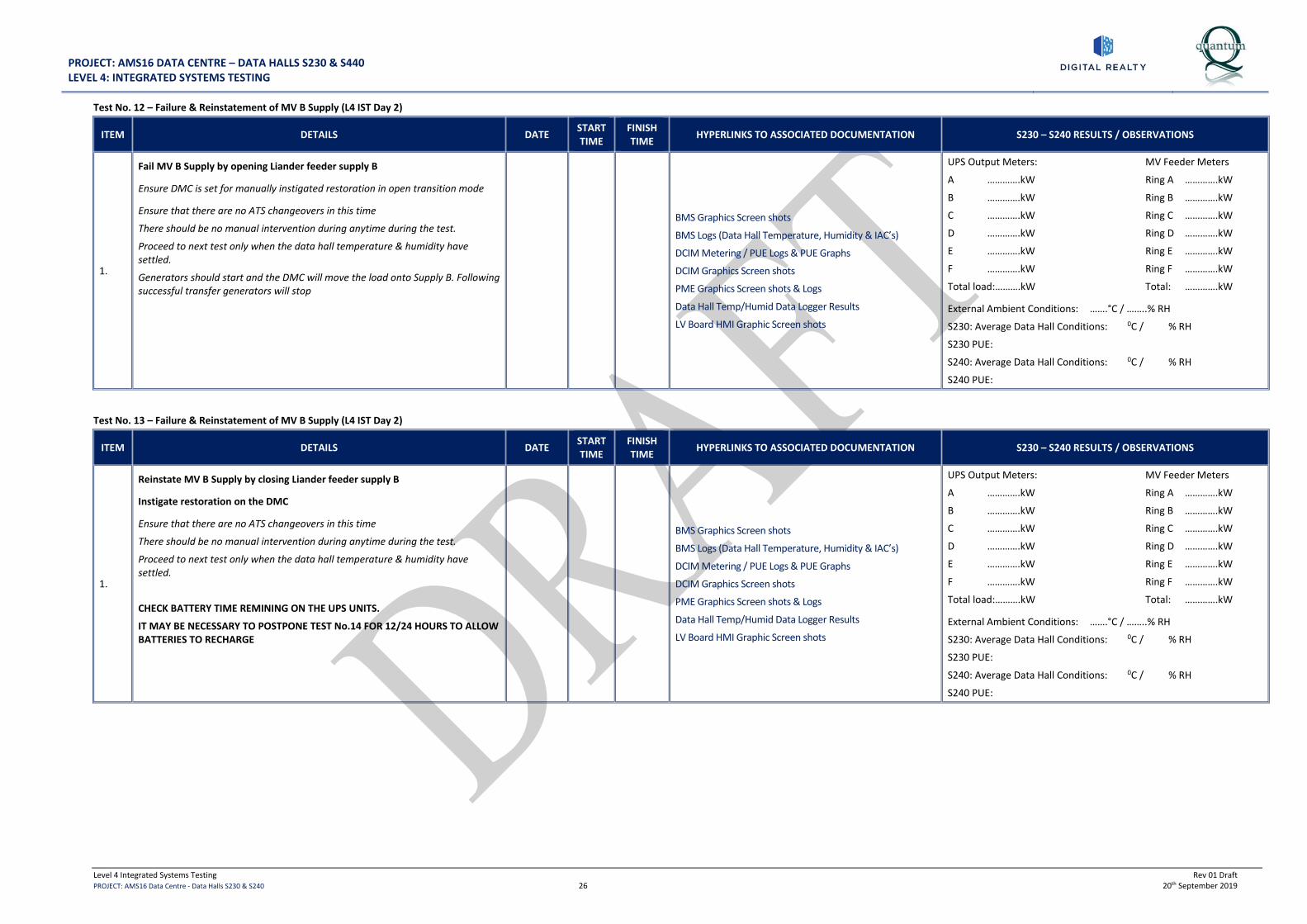
PROJECT: AMS16 DATA CENTRE – DATA HALLS S230 & S440 LEVEL 4: INTEGRATED SYSTEMS TESTING
Level 4 Integrated Systems Testing Rev 01 Draft PROJECT: AMS16 Data Centre - Data Halls S230 & S240 26 20th September 2019
Test No. 12 – Failure & Reinstatement of MV B Supply (L4 IST Day 2)
ITEM DETAILS DATE START TIME
FINISH TIME HYPERLINKS TO ASSOCIATED DOCUMENTATION S230 – S240 RESULTS / OBSERVATIONS
1.
Fail MV B Supply by opening Liander feeder supply B
Ensure DMC is set for manually instigated restoration in open transition mode
Ensure that there are no ATS changeovers in this time
There should be no manual intervention during anytime during the test.
Proceed to next test only when the data hall temperature & humidity have settled.
Generators should start and the DMC will move the load onto Supply B. Following successful transfer generators will stop
BMS Graphics Screen shots
BMS Logs (Data Hall Temperature, Humidity & IAC’s)
DCIM Metering / PUE Logs & PUE Graphs
DCIM Graphics Screen shots
PME Graphics Screen shots & Logs
Data Hall Temp/Humid Data Logger Results
LV Board HMI Graphic Screen shots
UPS Output Meters: MV Feeder Meters
A ………….kW Ring A ………….kW
B ………….kW Ring B ………….kW
C ………….kW Ring C ………….kW
D ………….kW Ring D ………….kW
E ………….kW Ring E ………….kW
F ………….kW Ring F ………….kW
Total load:……….kW Total: ………….kW
External Ambient Conditions: …….°C / ……..% RH
S230: Average Data Hall Conditions: 0C / % RH
S230 PUE:
S240: Average Data Hall Conditions: 0C / % RH
S240 PUE:
Test No. 13 – Failure & Reinstatement of MV B Supply (L4 IST Day 2)
ITEM DETAILS DATE START TIME
FINISH TIME HYPERLINKS TO ASSOCIATED DOCUMENTATION S230 – S240 RESULTS / OBSERVATIONS
1.
Reinstate MV B Supply by closing Liander feeder supply B
Instigate restoration on the DMC
Ensure that there are no ATS changeovers in this time
There should be no manual intervention during anytime during the test.
Proceed to next test only when the data hall temperature & humidity have settled.
CHECK BATTERY TIME REMINING ON THE UPS UNITS.
IT MAY BE NECESSARY TO POSTPONE TEST No.14 FOR 12/24 HOURS TO ALLOW BATTERIES TO RECHARGE
BMS Graphics Screen shots
BMS Logs (Data Hall Temperature, Humidity & IAC’s)
DCIM Metering / PUE Logs & PUE Graphs
DCIM Graphics Screen shots
PME Graphics Screen shots & Logs
Data Hall Temp/Humid Data Logger Results
LV Board HMI Graphic Screen shots
UPS Output Meters: MV Feeder Meters
A ………….kW Ring A ………….kW
B ………….kW Ring B ………….kW
C ………….kW Ring C ………….kW
D ………….kW Ring D ………….kW
E ………….kW Ring E ………….kW
F ………….kW Ring F ………….kW
Total load:……….kW Total: ………….kW
External Ambient Conditions: …….°C / ……..% RH
S230: Average Data Hall Conditions: 0C / % RH
S230 PUE:
S240: Average Data Hall Conditions: 0C / % RH
S240 PUE:
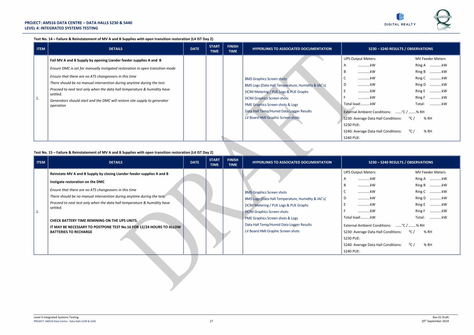
PROJECT: AMS16 DATA CENTRE – DATA HALLS S230 & S440 LEVEL 4: INTEGRATED SYSTEMS TESTING
Level 4 Integrated Systems Testing Rev 01 Draft PROJECT: AMS16 Data Centre - Data Halls S230 & S240 27 20th September 2019
Test No. 14 – Failure & Reinstatement of MV A and B Supplies with open transition restoration (L4 IST Day 2)
ITEM DETAILS DATE START TIME
FINISH TIME HYPERLINKS TO ASSOCIATED DOCUMENTATION S230 – S240 RESULTS / OBSERVATIONS
1.
Fail MV A and B Supply by opening Liander feeder supplies A and B
Ensure DMC is set for manually instigated restoration in open transition mode
Ensure that there are no ATS changeovers in this time
There should be no manual intervention during anytime during the test.
Proceed to next test only when the data hall temperature & humidity have settled.
Generators should start and the DMC will restore site supply to generator operation
BMS Graphics Screen shots
BMS Logs (Data Hall Temperature, Humidity & IAC’s)
DCIM Metering / PUE Logs & PUE Graphs
DCIM Graphics Screen shots
PME Graphics Screen shots & Logs
Data Hall Temp/Humid Data Logger Results
LV Board HMI Graphic Screen shots
UPS Output Meters: MV Feeder Meters
A ………….kW Ring A ………….kW
B ………….kW Ring B ………….kW
C ………….kW Ring C ………….kW
D ………….kW Ring D ………….kW
E ………….kW Ring E ………….kW
F ………….kW Ring F ………….kW
Total load:……….kW Total: ………….kW
External Ambient Conditions: …….°C / ……..% RH
S230: Average Data Hall Conditions: 0C / % RH
S230 PUE:
S240: Average Data Hall Conditions: 0C / % RH
S240 PUE:
Test No. 15 – Failure & Reinstatement of MV A and B Supplies with open transition restoration (L4 IST Day 2)
ITEM DETAILS DATE START TIME
FINISH TIME HYPERLINKS TO ASSOCIATED DOCUMENTATION S230 – S240 RESULTS / OBSERVATIONS
1.
Reinstate MV A and B Supply by closing Liander feeder supplies A and B
Instigate restoration on the DMC
Ensure that there are no ATS changeovers in this time
There should be no manual intervention during anytime during the test.
Proceed to next test only when the data hall temperature & humidity have settled.
CHECK BATTERY TIME REMINING ON THE UPS UNITS.
IT MAY BE NECESSARY TO POSTPONE TEST No.16 FOR 12/24 HOURS TO ALLOW BATTERIES TO RECHARGE
BMS Graphics Screen shots
BMS Logs (Data Hall Temperature, Humidity & IAC’s)
DCIM Metering / PUE Logs & PUE Graphs
DCIM Graphics Screen shots
PME Graphics Screen shots & Logs
Data Hall Temp/Humid Data Logger Results
LV Board HMI Graphic Screen shots
UPS Output Meters: MV Feeder Meters
A ………….kW Ring A ………….kW
B ………….kW Ring B ………….kW
C ………….kW Ring C ………….kW
D ………….kW Ring D ………….kW
E ………….kW Ring E ………….kW
F ………….kW Ring F ………….kW
Total load:……….kW Total: ………….kW
External Ambient Conditions: …….°C / ……..% RH
S230: Average Data Hall Conditions: 0C / % RH
S230 PUE:
S240: Average Data Hall Conditions: 0C / % RH
S240 PUE:

PROJECT: AMS16 DATA CENTRE – DATA HALLS S230 & S440 LEVEL 4: INTEGRATED SYSTEMS TESTING
Level 4 Integrated Systems Testing Rev 01 Draft PROJECT: AMS16 Data Centre - Data Halls S230 & S240 28 20th September 2019
Test No. 16 – Failure & Reinstatement of MV A and B Supplies with closed transition restoration (L4 IST Day 2)
ITEM DETAILS DATE START TIME
FINISH TIME HYPERLINKS TO ASSOCIATED DOCUMENTATION S230 – S240 RESULTS / OBSERVATIONS
1.
Fail MV A and B Supply by opening Liander feeder supplies A and B
Ensure DMC is set for manually instigated restoration in closed transition mode
Ensure that there are no ATS changeovers in this time
There should be no manual intervention during anytime during the test.
Proceed to next test only when the data hall temperature & humidity have settled.
Generators should start and the DMC will restore site supply to generator operation
BMS Graphics Screen shots
BMS Logs (Data Hall Temperature, Humidity & IAC’s)
DCIM Metering / PUE Logs & PUE Graphs
DCIM Graphics Screen shots
PME Graphics Screen shots & Logs
Data Hall Temp/Humid Data Logger Results
LV Board HMI Graphic Screen shots
UPS Output Meters: MV Feeder Meters
A ………….kW Ring A ………….kW
B ………….kW Ring B ………….kW
C ………….kW Ring C ………….kW
D ………….kW Ring D ………….kW
E ………….kW Ring E ………….kW
F ………….kW Ring F ………….kW
Total load:……….kW Total: ………….kW
External Ambient Conditions: …….°C / ……..% RH
S230: Average Data Hall Conditions: 0C / % RH
S230 PUE:
S240: Average Data Hall Conditions: 0C / % RH
S240 PUE:
Test No. 17 – Failure & Reinstatement of MV A and B Supplies with closed transition restoration (L4 IST Day 2)
ITEM DETAILS DATE START TIME
FINISH TIME HYPERLINKS TO ASSOCIATED DOCUMENTATION S230 – S240 RESULTS / OBSERVATIONS
1.
Reinstate MV A and B Supply by closing Liander feeder supplies A and B
Instigate restoration on the DMC
Ensure that there are no ATS changeovers in this time
There should be no manual intervention during anytime during the test.
Proceed to next test only when the data hall temperature & humidity have settled.
BMS Graphics Screen shots
BMS Logs (Data Hall Temperature, Humidity & IAC’s)
DCIM Metering / PUE Logs & PUE Graphs
DCIM Graphics Screen shots
PME Graphics Screen shots & Logs
Data Hall Temp/Humid Data Logger Results
LV Board HMI Graphic Screen shots
UPS Output Meters: MV Feeder Meters
A ………….kW Ring A ………….kW
B ………….kW Ring B ………….kW
C ………….kW Ring C ………….kW
D ………….kW Ring D ………….kW
E ………….kW Ring E ………….kW
F ………….kW Ring F ………….kW
Total load:……….kW Total: ………….kW
External Ambient Conditions: …….°C / ……..% RH
S230: Average Data Hall Conditions: 0C / % RH
S230 PUE:
S240: Average Data Hall Conditions: 0C / % RH
S240 PUE:
Test No. 18 – Step Down Load From 100% to 0% (L4 IST Day 2)
ITEM DETAILS DATE START TIME
FINISH TIME
HYPERLINKS TO ASSOCIATED DOCUMENTATION S230 RESULTS/ OBSERVATIONS S240 RESULTS/ OBSERVATIONS
1. Step Down Load from 100% to 0% in stepped decreases in Data Halls S230 & S240
Implement Fire Watch for 1 hour N/A N/A N/A

PROJECT: AMS16 DATA CENTRE – DATA HALLS S230 & S440 LEVEL 4: INTEGRATED SYSTEMS TESTING
Level 4 Integrated Systems Testing Rev 01 Draft PROJECT: AMS16 Data Centre - Data Halls S230 & S240 29 20th September 2019
8.0 ADDITIONAL TESTS REQUIRED BY DIGITAL REALTY TECHNICAL OPERATIONS TEAM (L4 IST DAY 2)
Test No. 01 – IAC Unit Humidifier Run on 100% Load for 8 hour duration (L4 IST Day 2)
ITEM DETAILS DATE START TIME
FINISH TIME
HYPERLINKS TO ASSOCIATED DOCUMENTATION S230 RESULTS/ OBSERVATIONS S240 RESULTS/ OBSERVATIONS
1.
With 100% load equally distributed (S230 2000 kW / S240 3000 kW).
Humidifier run with load over an 8 hour period to prove stability.
This can be carried out over an evening or weekend.
Tech ops have some de humidifiers which can be used to create demand, but as it will be winter we should have a humidity requirement.
BMS Graphics Screen shots
BMS Logs (Data Hall Temperature, Humidity & IAC’s)
DCIM Metering / PUE Logs & PUE Graphs
DCIM Graphics Screen shots
PME Graphics Screen shots
Data Hall Temp/Humid Data Logger Results
Total Utility Load: kW
S230 Data Hall IT Load: kW (…..%)
S230 PUE:
Data Hall Average Space Conditions: ……°C / …….% RH
IAC Unit Average Supply Air Temperature: …….°C
IAC Unit Average Return Air Temperature: ……..°C
External Ambient Conditions: …….°C / ……..% RH
Total Utility Load: kW
S240 Data Hall IT Load: kW (…..%)
S240 PUE:
Data Hall Average Space Conditions: ……°C / …….% RH
IAC Unit Average Supply Air Temperature: …….°C
IAC Unit Average Return Air Temperature: ……..°C
External Ambient Conditions: …….°C / ……..% RH
Test No. 02 – IAC Unit Process Cooling Water Volumetric flow rate test on 100% Load (L4 IST Day 2)
ITEM DETAILS DATE START TIME
FINISH TIME
HYPERLINKS TO ASSOCIATED DOCUMENTATION S230 RESULTS/ OBSERVATIONS S240 RESULTS/ OBSERVATIONS
1.
With 100% load equally distributed (S230 2000 kW / S240 3000 kW).
Measure the cooling water volumetric flowrate.
Mercury will need an ultrasonic flowmeter to test the volume.
BMS Graphics Screen shots
BMS Logs (Data Hall Temperature, Humidity & IAC’s)
DCIM Metering / PUE Logs & PUE Graphs
DCIM Graphics Screen shots
PME Graphics Screen shots
Data Hall Temp/Humid Data Logger Results
Ultrasonic flow meter results
Total Utility Load: kW
S230 Data Hall IT Load: kW (…..%)
S230 PUE:
Data Hall Average Space Conditions: ……°C / …….% RH
IAC Unit Average Supply Air Temperature: …….°C
IAC Unit Average Return Air Temperature: ……..°C
External Ambient Conditions: …….°C / ……..% RH
Total Utility Load: kW
S240 Data Hall IT Load: kW (…..%)
S240 PUE:
Data Hall Average Space Conditions: ……°C / …….% RH
IAC Unit Average Supply Air Temperature: …….°C
IAC Unit Average Return Air Temperature: ……..°C
External Ambient Conditions: …….°C / ……..% RH
Test No. 03 - IAC Units Power Loss Recovery Time on 100% Load (L4 IST Day 2)
ITEM DETAILS DATE START TIME
FINISH TIME
HYPERLINKS TO ASSOCIATED DOCUMENTATION S230 RESULTS/ OBSERVATIONS S240 RESULTS/ OBSERVATIONS
1.
With 100% load equally distributed (S230 2000 kW / S240 3000 kW).
Fail Power to all IAC units
Reinstate power to all IAC units
Record recovery time for stable conditions within the Data Hall
BMS Graphics Screen shots
BMS Logs (Data Hall Temperature, Humidity & IAC’s)
DCIM Metering / PUE Logs & PUE Graphs
DCIM Graphics Screen shots
PME Graphics Screen shots
Data Hall Temp/Humid Data Logger Results
Total Utility Load: kW
S230 Data Hall IT Load: kW (…..%)
S230 PUE:
Data Hall Average Space Conditions: ……°C / …….% RH
IAC Unit Average Supply Air Temperature: …….°C
IAC Unit Average Return Air Temperature: ……..°C
External Ambient Conditions: …….°C / ……..% RH
IAC Unit Recovery Time: : …….
Total Utility Load: kW
S240 Data Hall IT Load: kW (…..%)
S240 PUE:
Data Hall Average Space Conditions: ……°C / …….% RH
IAC Unit Average Supply Air Temperature: …….°C
IAC Unit Average Return Air Temperature: ……..°C
External Ambient Conditions: …….°C / ……..% RH
IAC Unit Recovery Time: : …….

PROJECT: AMS16 DATA CENTRE – DATA HALLS S230 & S440 LEVEL 4: INTEGRATED SYSTEMS TESTING
Level 4 Integrated Systems Testing Rev 01 Draft PROJECT: AMS16 Data Centre - Data Halls S230 & S240 30 20th September 2019
Test No. 04 - UPS commissioning when on load – Demonstration of Maintenance on the modules L4 IST Day 2)
ITEM DETAILS DATE START TIME
FINISH TIME
HYPERLINKS TO ASSOCIATED DOCUMENTATION S230 RESULTS/ OBSERVATIONS S240 RESULTS/ OBSERVATIONS
1. With the UPS units on Load, the UPS manufacturer is to demonstrate maintenance on the modules .i.e how to remove and replace
Demonstration Witness Report N/A N/A

PROJECT ‐ PARIS CDG15 ‐ PHASE 1
SECTION 7 AMS 16 PROJECT – EXAMPLE LEVEL 5 SCRIPT (PRODUCED BY QUANTUM)

PROJECT: AMS16 DATA CENTRE – S202 DATA HALLS S230 & S240 INTEGRATED SYSTEMS TESTING - FINAL TEST RESULTS
quantum
Performance & Integrated Systems Testing Rev 00 Draft PROJECT: AMS16 Data Centre – S202 Data Halls S230 & S240 1 October 2019
AMS16 DATA CENTRE S202 - DATA HALLS S230 & S240
INTEGRATED SYSTEMS TESTING - FINAL TEST RESULTS
REVISION STATUS
DATE AUTHOR CHECKED REVISION DETAILS REVISION NO.
October 2019 D. Umansky – QAL Draft for Discussion 00
TESTING WITNESSED / AUTHORISED BY
COMPANY NAME DATE
Digital Realty Ltd.(DLR) P. Sheridan
Quantum Associates Ltd. (QAL)
Mercury Engineering
ARUP
HYPERLINK TO COMMISSIONING COMPLETION LETTER
Commissioning Completion Letter
HYPERLINK TO DCIM PUE LOGS, GRAPHS & CURVES
DCIM Metering / PUE Log & PUE Graphs
DCIM PUE Curve for Heat Load Steps 5% to 100%
DRAFT ISSUE FOR DISCUSSION
S230 SUMMARY OF ACHIEVED POWER USAGE EFFICIENCY (PUE) DURING IST
S230 Average PUE value at 100% Load
S230 Data Hall Achieved IT Load (kW) kW
S230 Data Hall IAC Unit Average Supply Air Temperature 100% Load °C
S230 Data Hall IAC Unit Average Return Air Temperature 100% Load °C
S230 Data Hall Average Temperature & Humidity at 100% Load °C / % RH
External Ambient Conditions °C / % RH
S240 SUMMARY OF ACHIEVED POWER USAGE EFFICIENCY (PUE) DURING IST
S240 Average PUE value at 100% Load
S240 Data Hall Achieved IT Load (kW) kW
S240 Data Hall IAC Unit Average Supply Air Temperature 100% Load °C
S240 Data Hall IAC Unit Average Return Air Temperature 100% Load °C
S240 Data Hall Average Temperature & Humidity at 100% Load °C / % RH
External Ambient Conditions °C / % RH

PROJECT: AMS16 DATA CENTRE – S202 DATA HALLS S230 & S240 INTEGRATED SYSTEMS TESTING - FINAL TEST RESULTS
quantum
Performance & Integrated Systems Testing Rev 00 Draft PROJECT: AMS16 Data Centre – S202 Data Halls S230 & S240 2 October 2019
INDEX
1.0 INTRODUCTION ................................................................................................................................................ 3 BASIS OF THE ELECTRICAL SERVICES AND POWER SYSTEMS DESIGN ............................................................................................ 3
BASIS OF THE MECHANICAL SERVICES DESIGN ....................................................................................................................... 3
TESTING OBJECTIVES ........................................................................................................................................................ 3
2.0 PRE-REQUISITES TO IST PROGRAMME COMMENCEMENT....................................................................... 4 PRE-START BRIEFING SCHEDULE ......................................................................................................................................... 4
PRE-START CHECKLIST / HEALTH & SAFETY ........................................................................................................................... 4
PREREQUISITES TO COMMENCEMENT OF IST ......................................................................................................................... 5
SPECIFIC REQUIREMENTS – CONFIRMED DAILY PRIOR TO TESTS ................................................................................................ 6
3.0 TEAM RESPONSIBILITIES / IST LOGISTICS .................................................................................................. 7 4.0 TEST PROCEDURES ........................................................................................................................................ 8
TEST OBJECTIVES & TEST ACCEPTANCE CRITERIA: ................................................................................................................... 8
CONDITIONS TO BE MAINTAINED WITHIN SERVER ROOMS, ANCILLARY AREAS AND ASSOCIATED PLANT: ............................................... 8
5.0 STEPPED HEAT LOAD TEST AND MECHANICAL RESILIENCE TEST PROCEDURES (IST DAY 1) ......... 9 TEST NO. 01 – PRE-START CHECK (IST DAY 1) ...................................................................................................................... 9
TEST NO. 02 – DATA HALL NORMALISATION PERIOD (IST DAY 1) ............................................................................................. 9
TEST NO. 03 – LOAD DATA HALL TO 10% (IST DAY 1) ........................................................................................................... 9
TEST NO. 04 – LOAD DATA HALL TO 15% (IST DAY 1) ..........................................................................................................10
TEST NO. 05 – LOAD DATA HALL TO 25% (IST DAY 1) ..........................................................................................................10
TEST NO. 06 – LOAD DATA HALL TO 50% (IST DAY 1) ..........................................................................................................11
TEST NO. 07 – LOAD DATA HALL TO 75% (IST DAY 1) ..........................................................................................................11
TEST NO. 08 – LOAD DATA HALL TO 100% (IST DAY 1) ........................................................................................................12
TEST NO. 09 – FAIL 1 NUMBER IAC UNIT IN EACH DATA HALL (IST DAY 1) ...............................................................................12
TEST NO. 10 – FAIL 1 NUMBER IAC UNIT IN EACH DATA HALL (IST DAY 1) ...............................................................................13
TEST NO. 11 – FAIL NETWORK BETWEEN IAC UNITS 05 & 06 IN EACH DATA HALL (IST DAY 1)......................................................13
TEST NO. 12 – FAIL NETWORK BETWEEN IAC UNITS 01 & 10 IN EACH DATA HALL (IST DAY 1)......................................................13
TEST NO. 13 – ISOLATE ONE SIDE OF THE MAKE-UP WATER RING MAIN TO THE IAC UNITS IN EACH DATA HALL (IST DAY 1) ...............14
TEST NO. 14 – FAIL ONE DATA HALL AHU IN EACH DATA HALL (IST DAY 1) ..............................................................................14
TEST NO. 15 – STEP DOWN LOAD FROM 100% TO 0% (IST DAY 1) .........................................................................................14
6.0 ELECTRICAL RESILIENCE TOLERANCE TESTING PROCEDURES AT 100% LOAD (IST DAY 2) .......... 15
TEST NO. 01 – PRE-START CHECK (IST DAY 2) .................................................................................................................... 15
TEST NO. 02 – DTA HALL NORMALISATION PERIOD (IST DAY 2) ............................................................................................. 15
TEST NO. 03– LOAD DATA HALLS TO 100% (IST DAY 2) ....................................................................................................... 15
TEST NO. 04 – FAILURE OF MV A SUPPLY (IST DAY 2) ......................................................................................................... 16
TEST NO. 05 – REINSTATEMENT OF MV A SUPPLY (IST DAY 2) .............................................................................................. 16
TEST NO. 06 – FAILURE OF MV B SUPPLY (IST DAY 2) .......................................................................................................... 17
TEST NO. 07 – REINSTATEMENT OF MV B SUPPLY (IST DAY 2) ............................................................................................... 17
TEST NO. 08 – FAILURE OF MV A AND B SUPPLIES [OPEN TRANSITION RESTORATION] (IST DAY 2) ....................................... 18
TEST NO. 09 – REINSTATEMENT OF MV A AND B SUPPLIES [OPEN TRANSITION RESTORATION] (IST DAY 2) ............................ 18
TEST NO. 10 – FAILURE OF MV A AND B SUPPLIES [CLOSED TRANSITION RESTORATION] (IST DAY 2).................................... 19
TEST NO. 11 – REINSTATEMENT OF MV A AND B SUPPLIES [CLOSED TRANSITION RESTORATION] (IST DAY 2) ........................ 19
TEST NO. 12 – STEP DOWN LOAD FROM 100% TO 0% (IST DAY 2) ........................................................................................ 19
8.0 PHOTOGRAPHS OF HOT AISLE CONTAINMENT SIMULATION ................................................................ 20

PROJECT: AMS16 DATA CENTRE – S202 DATA HALLS S230 & S240 INTEGRATED SYSTEMS TESTING - FINAL TEST RESULTS
quantum
Performance & Integrated Systems Testing Rev 00 Draft PROJECT: AMS16 Data Centre – S202 Data Halls S230 & S240 3 October 2019
1.0 INTRODUCTION
The Project is the construction of two new Data Halls (S230 & S240) in the Data Centre, including support areas as follows:
• S230: Data Hall Rated at 2000 kW maximum design capacity
• S240: Data Hall Rated at 3000 kW maximum design capacity
• Five number electrical switchrooms each with UPS for N+1 resilience
• 8 number 2.75 MVA/2.2 MW/10.5kV Generators
• S230: 7 number Indirect Adiabatic Cooling Units (IAC) providing N+1 resilience
• S240: 10 number Indirect Adiabatic Cooling Units (IAC) providing N+1 resilience
• Mechanical plant areas for support systems
Basis of the Electrical Services and Power Systems Design
The site comprises of a 20/10.5kV substation distributing 10.5 kV to the MV Switchboards. The main MV switchgear further distributes 10.5 kV supplies around site to Data Hall switch rooms.
The site is supported by 8 number MV Generators.
The Data Halls are supported by 6 number LV Switchboards (S202-SBLV-A, S202-SBLV-B, S202-SBLV-C, S202-SBLV-D, S202-SBLV-E and S202-SBLV-E).
Each LV Switchboard is supplied by a packaged substation consisting of externally mounted 10.5kV/400V transformer & Ring Main Unit. Each LV Switchboard is provided with a UPS and ancillary plant.
Each substation is fed via the sites MV distribution system. The switchrooms serve the Data Halls via overhead bus bars which drop to raised floor level on entry to the Data Halls.
Critical mechanical equipment is provided with A and B feeds with integral automatic changeover where required.
Basis of the Mechanical Services Design
Data Hall S230 is cooled by an arrangement of 7 Number IAC Units arranged to provide N+1 resilience.
Data Hall S240 is cooled by an arrangement of 10 Number IAC Units arranged to provide N+1 resilience.
A make-up water supply system is provided to feed the IAC units from underground storage tanks, break tanks and booster pump sets with micron filtration equipment.
Data Halls S230 & S240 are each provided with 2 number Air Handling Units (½N / ½N) each with integral steam humidifier and external DX condenser units for the cooling coil. These provide fresh air to the Data Halls and maintain a positive pressure in the Hall relative to the access corridor. These also provide for humidification and de-humidification of the Data Halls. Supply air is ducted to each Data Hall via connections to the discharge ductwork from two of the IAC Units
Each of the UPS / LV Switch rooms are provided with 2 number DX CRAC Units (N+1) for cooling
Each of the UPS Battery Rooms are provided with 2 number Split DX Cooling Units (N+1), extract system and hydrogen detection system
Testing Objectives
The principal tests are as follows:
1. To demonstrate the Data Hall Mechanical and Electrical Systems working in a simulated Hot Aisle Containment configuration (a temporary Hot Aisle structure incorporating load banks was configured within the Data Hall to simulate an operational Hot Aisle installation). Refer to photos of Hot Aisle simulation in Section 7
2. Room Validation Tests to prove the performance of the installed cooling systems serving the Data Hall areas under full load conditions.
3. IAC unit performance load tests and all associated plant and equipment that is critical to the environmental conditions within the Data Hall.
4. Tests with all systems healthy under full load, in fault and under maintenance scenarios.
5. Electrical Validation testing to prove the performance of the Main Electrical Distribution System.
6. UPS performance and resilience.
7. To provide an operational PUE Graph throughout the heat load test
Note: It is not the intention to repeat any of the commissioning /certification tests that must be completed as a prerequisite to these tests. The principal aim is to assess the overall impact of systems operation on the fully loaded facility.
The purpose of this document is to detail the procedures to be undertaken, confirm responsibilities and prerequisites to the commencement of the tests – and finally to review requirements for final pro-forma record documentation.
The testing will be undertaken in the following sequence:
1. Stepped Heat Load Test with Mechanical Fault Tolerance Tests at simulated 100% Heat Load (DAY 1)
o Simulated heat load – Stepped Loads 10% to 100% (incremental load steps)
2. Electrical Resilience Tests at simulated 100% Heat Load (DAY 2)
o Simulated 100% heat load

PROJECT: AMS16 DATA CENTRE – S202 DATA HALLS S230 & S240 INTEGRATED SYSTEMS TESTING - FINAL TEST RESULTS
quantum
Performance & Integrated Systems Testing Rev 00 Draft PROJECT: AMS16 Data Centre – S202 Data Halls S230 & S240 4 October 2019
2.0 PRE-REQUISITES TO IST PROGRAMME COMMENCEMENT
Pre-Start Briefing Schedule
Co-ordination briefings to be held on the following basis up to the start of Integrated Systems Testing. Mercury Engineering will chair the briefings, at which the pre-start checklist will be reviewed.
Item Description Attendees Date Completed
1 IST Pre-Start Briefing
a) General review of pre-start checklist confirming all health & safety / general logistics issues covered.
b) Confirm start dates for tests and review of briefing dates accordingly.
c) Confirm approval of this document.
All personnel included in tests
2 IST Daily Briefings
a) Debriefing held following each set of tests each morning.
b) Review of forthcoming tests and responsibilities.
c) Sign off sheet to be incorporated into test method statements.
All personnel included in tests
Pre-Start Checklist / Health & Safety
Item Description Action Date Cleared
1 Set up Control Room
a) Networked BMS Head-End
b) All head-ends to be provided with colour printer, and sufficient paper
c) Software back-ups to be provided for BMS
d) Resilient power supplies for all the above plus additional spare supplies for additional laptops for IST controller & for BMS head-end
e) Room to contain a set of As-fitted schematics for reference.
f) Radio base station – provide 10no digital radios - (Spare radio batteries and chargers) to be located in control room. – with sufficient power supply
g) Sufficient desk space for all above PCs and equipment. Seating for up to 8 within control room
Mercury
2 Agree Briefing/Base Area
Mercury to provide necessary seating / layout table Mercury
3 Personnel confirmed by each organisation
a) Team responsibilities and locations agreed (Section 3).
b) Contact details included in schedule
c) Contractors to confirm personnel
d) All personnel inducted into site
Mercury
4 Radio Communications
Provide 10no. digital radios for IST
(1 no radio required per team plus spares).
Mercury
5 Provide necessary Health & Safety signage
a) escape route designation
b) key room identification (i.e. switchrooms, plantrooms, control room etc)
c) plant labelling
Mercury

PROJECT: AMS16 DATA CENTRE – S202 DATA HALLS S230 & S240 INTEGRATED SYSTEMS TESTING - FINAL TEST RESULTS
quantum
Performance & Integrated Systems Testing Rev 00 Draft PROJECT: AMS16 Data Centre – S202 Data Halls S230 & S240 5 October 2019
Prerequisites to Commencement of IST
Item Description Action Cleared
1 All Electrical systems complete / signed-off and Test Certification issued to DLR
Mercury
2 All MV and Generator Control Sequences proven, witnessed / signed-off and Test Certification issued to DLR
Mercury
3 All Mechanical systems complete / signed-off and Test Certification issued to DLR
Mercury
4 BMS & PME commissioning complete and signed off and Test Certification issued to DLR
Mercury
5 All Fire detection & Protection systems complete & demonstrated to Local Building Control Authority and Test Certification issued to DLR
Mercury
6 Secured access controlled doors commissioning complete Mercury
7 Load banks: heaters installed to agreed configuration in the Data Hall. Mercury
8 Temperature logging devices to be installed at agreed locations. Mercury

PROJECT: AMS16 DATA CENTRE – S202 DATA HALLS S230 & S240 INTEGRATED SYSTEMS TESTING - FINAL TEST RESULTS
quantum
Performance & Integrated Systems Testing Rev 00 Draft PROJECT: AMS16 Data Centre – S202 Data Halls S230 & S240 6 October 2019
Specific Requirements – Confirmed Daily Prior to Tests
Item Description Action Cleared
1
Detailed IST programme agreed and notified to all personnel for synchronisation of observations.
To be confirmed that no breaks allowed during each test.
All
2 All systems as defined in ‘auto’ operation Mercury
3 Safety procedures reconfirmed & briefed
a) Localised fire extinguishers to be positioned throughout the Data Hall
b) Escape Routes to be clearly identified
c) Water Mist system to be isolated
d) Prior to the tests the data centre is to be fully surveyed for means of escape / safety
e) Rooms to be fully cleaned
Mercury
4 Emergency procedures reconfirmed
If any member of the test team notes any emergency situation :-
a) Call of ‘Emergency, Emergency, Emergency’ is to be made
b) Control room to respond
o All parties must then hold radio silence
o Caller should then advise :
• name
• area of work
• nature of emergency
• requirement (e.g., assistance, ambulance)
c) Control room to confirm message received and take appropriate action
If temperature within any room exceeds 40 degC (ASHRAE range for failure scenario) then ‘abort….abort’ command will be given.
If abort is required :-
a) control room will advise on radio : ‘abort...abort’
b) Supplies to heat loads to be isolated within Data Hall by Mercury
All
Item Description Action Cleared
5 Clear all event logs and synchronise all control systems clocks on the following :-
a) BMS, DCIM & EMS
b) Real-time logging equipment
Mercury
6 Ensure :-
a) All plant labelling and referencing is consistent with record drawings.
b) Temperature & humidity data logging in place and operating.
Mercury

PROJECT: AMS16 DATA CENTRE – S202 DATA HALLS S230 & S240 INTEGRATED SYSTEMS TESTING - FINAL TEST RESULTS
quantum
Performance & Integrated Systems Testing Rev 00 Draft PROJECT: AMS16 Data Centre – S202 Data Halls S230 & S240 7 October 2019
3.0 TEAM RESPONSIBILITIES / IST LOGISTICS
Party Responsibility / Outline Location Personnel Names
Mercury
Overall package contractor co-ordination. Site safety co-ordination.
Provision of radio communications. Provision of temperature & humidity data loggers.
Provision of Hot Aisle containment simulation. Provision of Heaters/Load Banks.
Attendance at control room and representative locations around site.
Mercury Co-ordination & overall control of IST demonstration witnessing, review of testing and commissioning report results from package contractors. Attendance at control room and representative locations around site.
Mercury
Set-up and management of load banks (heaters).
Overall co-ordination of electrical services elements - including failure of supplies as detailed within test procedures. AP required for LV switchrooms.
Attendance required throughout at representative locations in Data Hall (for load management) and LV switchrooms.
Mercury
Review / reporting on mechanical systems performance through heat load test during IST,
Attendance in mechanical plantrooms during power resilience tests.
Review / reporting on mechanical plant status.
Attendance at external Plant (IAC Units & Make-Up Water Supply System)
Mercury Mechanical commissioning checks
Quantum Associates
Management of IST Step Procedures in conjunction with the Mercury Engineering Management Team.
Attendance at control room and representative locations around site.
Witness & validation of IST Testing and issue of Final Testing Report
Digital Realty Witness / review of testing. Overall review of testing and general advice / comment as programme progresses. Attendance at control room and representative locations around site.
UPS Contractor Observe & reporting on UPS status. Attendance at UPS.
Generator Contractor Observe & reporting on Generator status. Attendance at Generators.
IAC Contractor Observe & reporting on IAC unit status. Attendance at Data Hall IAC units.
BMS Contractor Observe & reporting on BMS & mechanical systems performance through heat load test & IST.
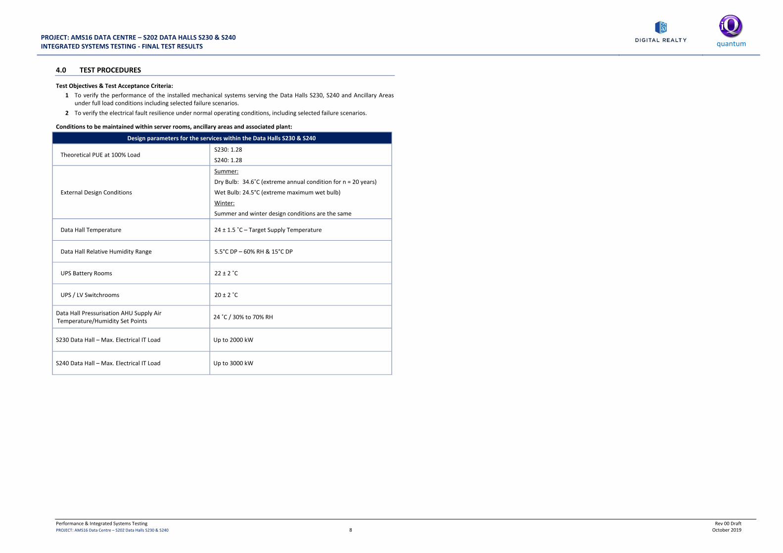
PROJECT: AMS16 DATA CENTRE – S202 DATA HALLS S230 & S240 INTEGRATED SYSTEMS TESTING - FINAL TEST RESULTS
quantum
Performance & Integrated Systems Testing Rev 00 Draft PROJECT: AMS16 Data Centre – S202 Data Halls S230 & S240 8 October 2019
4.0 TEST PROCEDURES
Test Objectives & Test Acceptance Criteria:
1 To verify the performance of the installed mechanical systems serving the Data Halls S230, S240 and Ancillary Areas under full load conditions including selected failure scenarios.
2 To verify the electrical fault resilience under normal operating conditions, including selected failure scenarios.
Conditions to be maintained within server rooms, ancillary areas and associated plant:
Design parameters for the services within the Data Halls S230 & S240
Theoretical PUE at 100% Load S230: 1.28
S240: 1.28
External Design Conditions
Summer:
Dry Bulb: 34.6˚C (extreme annual condition for n = 20 years)
Wet Bulb: 24.5°C (extreme maximum wet bulb)
Winter:
Summer and winter design conditions are the same
Data Hall Temperature 24 ± 1.5 ˚C – Target Supply Temperature
Data Hall Relative Humidity Range 5.5°C DP – 60% RH & 15°C DP
UPS Battery Rooms 22 ± 2 ˚C
UPS / LV Switchrooms 20 ± 2 ˚C
Data Hall Pressurisation AHU Supply Air Temperature/Humidity Set Points
24 ˚C / 30% to 70% RH
S230 Data Hall – Max. Electrical IT Load Up to 2000 kW
S240 Data Hall – Max. Electrical IT Load Up to 3000 kW

PROJECT: AMS16 DATA CENTRE – S202 DATA HALLS S230 & S240 INTEGRATED SYSTEMS TESTING - FINAL TEST RESULTS
quantum
Performance & Integrated Systems Testing Rev 00 Draft PROJECT: AMS16 Data Centre – S202 Data Halls S230 & S240 9 October 2019
5.0 STEPPED HEAT LOAD TEST AND MECHANICAL RESILIENCE TEST PROCEDURES (IST DAY 1)
Test No. 01 – Pre-Start Check (IST Day 1)
ITEM DETAILS DATE START TIME
FINISH TIME
HYPERLINKS TO ASSOCIATED DOCUMENTATION
S230 RESULTS / OBSERVATIONS S240 RESULTS/ OBSERVATIONS
1.
Ensure all systems are operational under automatic control and clear of any alarms prior to proceeding with any tests.
All plant and systems verified operational enabling test continuation.
N/A
Expected Result:
All plant verified as operational under automatic control.
No fault alarms on BMS (except IAC low Return Air Temp)
Expected Result:
All plant verified as operational under automatic control.
No fault alarms on BMS (except IAC low Return Air Temp)
Test No. 02 – Data Hall Normalisation Period (IST Day 1)
ITEM DETAILS DATE START TIME
FINISH TIME
HYPERLINKS TO ASSOCIATED DOCUMENTATION
S230 RESULTS/ OBSERVATIONS S240 RESULTS/ OBSERVATIONS
1.
All systems operational with no load.
Ensure room is stable for a period of time before taking load and temperature measurements.
Proceed only once measurements are complete.
BMS Graphics Screen shots
BMS Logs (Data Hall Temperature, Humidity & IAC’s)
DCIM Metering / PUE Logs & PUE Graphs
DCIM Graphics Screen shots
PME Graphics Screen shots
Data Hall Temp/Humid Data Logger Results
Total Utility Load: kW
Data Hall IT Load: 0 kW (0%)
No Heat Load applied.
Total Utility Load: kW
Data Hall IT Load: 0 kW (0%)
No Heat Load applied.
Test No. 03 – Load Data Hall to 10% (IST Day 1)
ITEM DETAILS DATE START TIME
FINISH TIME
HYPERLINKS TO ASSOCIATED DOCUMENTATION
S230 RESULTS/ OBSERVATIONS S240 RESULTS/ OBSERVATIONS
1.
Apply 10% load (200 kW) equally distributed in Data Hall S230.
Ensure Data Hall is stable for a period of time before taking load and temperature measurements.
Proceed only once measurements are complete.
Apply 10% load (300 kW) equally distributed in Data Hall S240.
Ensure Data Hall is stable for a period of time before taking load and temperature measurements.
Proceed only once measurements are complete.
BMS Graphics Screen shots
BMS Logs (Data Hall Temperature, Humidity & IAC’s)
DCIM Metering / PUE Logs & PUE Graphs
DCIM Graphics Screen shots
PME Graphics Screen shots
Data Hall Temp/Humid Data Logger Results
Total Utility Load: kW
S230 Data Hall IT Load: kW (…..%)
S230 PUE:
Data Hall Average Space Conditions: ……°C / …….% RH
IAC Unit Average Supply Air Temperature: …….°C
IAC Unit Average Return Air Temperature: ……..°C
External Ambient Conditions: …….°C / ……..% RH
Total Utility Load: kW
S240 Data Hall IT Load: kW (…..%)
S240 PUE:
Data Hall Average Space Conditions: ……°C / …….% RH
IAC Unit Average Supply Air Temperature: …….°C
IAC Unit Average Return Air Temperature: ……..°C
External Ambient Conditions: …….°C / ……..% RH

PROJECT: AMS16 DATA CENTRE – S202 DATA HALLS S230 & S240 INTEGRATED SYSTEMS TESTING - FINAL TEST RESULTS
quantum
Performance & Integrated Systems Testing Rev 00 Draft PROJECT: AMS16 Data Centre – S202 Data Halls S230 & S240 10 October 2019
Test No. 04 – Load Data Hall to 15% (IST Day 1)
ITEM DETAILS DATE START TIME
FINISH TIME
HYPERLINKS TO ASSOCIATED DOCUMENTATION
S230 RESULTS/ OBSERVATIONS S240 RESULTS/ OBSERVATIONS
1.
Apply 15% load (300 kW) equally distributed in Data Hall S230.
Ensure Data Hall is stable for a period of time before taking load and temperature measurements.
Proceed only once measurements are complete.
Apply 15% load (450 kW) equally distributed in Data Hall S240.
Ensure Data Hall is stable for a period of time before taking load and temperature measurements.
Proceed only once measurements are complete.
BMS Graphics Screen shots
BMS Logs (Data Hall Temperature, Humidity & IAC’s)
DCIM Metering / PUE Logs & PUE Graphs
DCIM Graphics Screen shots
PME Graphics Screen shots
Data Hall Temp/Humid Data Logger Results
Total Utility Load: kW
S230 Data Hall IT Load: kW (…..%)
S230 PUE:
Data Hall Average Space Conditions: ……°C / …….% RH
IAC Unit Average Supply Air Temperature: …….°C
IAC Unit Average Return Air Temperature: ……..°C
External Ambient Conditions: …….°C / ……..% RH
Total Utility Load: kW
S240 Data Hall IT Load: kW (…..%)
S240 PUE:
Data Hall Average Space Conditions: ……°C / …….% RH
IAC Unit Average Supply Air Temperature: …….°C
IAC Unit Average Return Air Temperature: ……..°C
External Ambient Conditions: …….°C / ……..% RH
Test No. 05 – Load Data Hall to 25% (IST Day 1)
ITEM DETAILS DATE START TIME
FINISH TIME
HYPERLINKS TO ASSOCIATED DOCUMENTATION
S230 RESULTS/ OBSERVATIONS S240 RESULTS/ OBSERVATIONS
1.
Apply 25% load (500 kW) equally distributed in Data Hall S230.
Ensure Data Hall is stable for a period of time before taking load and temperature measurements.
Proceed only once measurements are complete.
Apply 25% load (750 kW) equally distributed in Data Hall S240.
Ensure Data Hall is stable for a period of time before taking load and temperature measurements.
Proceed only once measurements are complete.
BMS Graphics Screen shots
BMS Logs (Data Hall Temperature, Humidity & IAC’s)
DCIM Metering / PUE Logs & PUE Graphs
DCIM Graphics Screen shots
PME Graphics Screen shots
Data Hall Temp/Humid Data Logger Results
Total Utility Load: kW
S230 Data Hall IT Load: kW (…..%)
S230 PUE:
Data Hall Average Space Conditions: ……°C / …….% RH
IAC Unit Average Supply Air Temperature: …….°C
IAC Unit Average Return Air Temperature: ……..°C
External Ambient Conditions: …….°C / ……..% RH
Total Utility Load: kW
S240 Data Hall IT Load: kW (…..%)
S240 PUE:
Data Hall Average Space Conditions: ……°C / …….% RH
IAC Unit Average Supply Air Temperature: …….°C
IAC Unit Average Return Air Temperature: ……..°C
External Ambient Conditions: …….°C / ……..% RH

PROJECT: AMS16 DATA CENTRE – S202 DATA HALLS S230 & S240 INTEGRATED SYSTEMS TESTING - FINAL TEST RESULTS
quantum
Performance & Integrated Systems Testing Rev 00 Draft PROJECT: AMS16 Data Centre – S202 Data Halls S230 & S240 11 October 2019
Test No. 06 – Load Data Hall to 50% (IST Day 1)
ITEM DETAILS DATE START TIME
FINISH TIME
HYPERLINKS TO ASSOCIATED DOCUMENTATION
S230 RESULTS/ OBSERVATIONS S240 RESULTS/ OBSERVATIONS
1.
Apply 50% load (1000 kW) equally distributed in Data Hall S230.
Ensure Data Hall is stable for a period of time before taking load and temperature measurements.
Proceed only once measurements are complete.
Apply 50% load (1500 kW) equally distributed in Data Hall S240.
Ensure Data Hall is stable for a period of time before taking load and temperature measurements.
Proceed only once measurements are complete.
BMS Graphics Screen shots
BMS Logs (Data Hall Temperature, Humidity & IAC’s)
DCIM Metering / PUE Logs & PUE Graphs
DCIM Graphics Screen shots
PME Graphics Screen shots
Data Hall Temp/Humid Data Logger Results
Total Utility Load: kW
S230 Data Hall IT Load: kW (…..%)
S230 PUE:
Data Hall Average Space Conditions: ……°C / …….% RH
IAC Unit Average Supply Air Temperature: …….°C
IAC Unit Average Return Air Temperature: ……..°C
External Ambient Conditions: …….°C / ……..% RH
Total Utility Load: kW
S240 Data Hall IT Load: kW (…..%)
S240 PUE:
Data Hall Average Space Conditions: ……°C / …….% RH
IAC Unit Average Supply Air Temperature: …….°C
IAC Unit Average Return Air Temperature: ……..°C
External Ambient Conditions: …….°C / ……..% RH
Test No. 07 – Load Data Hall to 75% (IST Day 1)
ITEM DETAILS DATE START TIME
FINISH TIME
HYPERLINKS TO ASSOCIATED DOCUMENTATION
S230 RESULTS/ OBSERVATIONS S240 RESULTS/ OBSERVATIONS
1.
Apply 75% load (1500 kW) equally distributed in Data Hall S230.
Ensure Data Hall is stable for a period of time before taking load and temperature measurements.
Proceed only once measurements are complete.
Apply 75% load (2250 kW) equally distributed in Data Hall S240.
Ensure Data Hall is stable for a period of time before taking load and temperature measurements.
Proceed only once measurements are complete.
BMS Graphics Screen shots
BMS Logs (Data Hall Temperature, Humidity & IAC’s)
DCIM Metering / PUE Logs & PUE Graphs
DCIM Graphics Screen shots
PME Graphics Screen shots
Data Hall Temp/Humid Data Logger Results
Total Utility Load: kW
S230 Data Hall IT Load: kW (…..%)
S230 PUE:
Data Hall Average Space Conditions: ……°C / …….% RH
IAC Unit Average Supply Air Temperature: …….°C
IAC Unit Average Return Air Temperature: ……..°C
External Ambient Conditions: …….°C / ……..% RH
Total Utility Load: kW
S240 Data Hall IT Load: kW (…..%)
S240 PUE:
Data Hall Average Space Conditions: ……°C / …….% RH
IAC Unit Average Supply Air Temperature: …….°C
IAC Unit Average Return Air Temperature: ……..°C
External Ambient Conditions: …….°C / ……..% RH

PROJECT: AMS16 DATA CENTRE – S202 DATA HALLS S230 & S240 INTEGRATED SYSTEMS TESTING - FINAL TEST RESULTS
quantum
Performance & Integrated Systems Testing Rev 00 Draft PROJECT: AMS16 Data Centre – S202 Data Halls S230 & S240 12 October 2019
Test No. 08 – Load Data Hall to 100% (IST Day 1)
ITEM DETAILS DATE START TIME
FINISH TIME
HYPERLINKS TO ASSOCIATED DOCUMENTATION
S230 RESULTS/ OBSERVATIONS S240 RESULTS/ OBSERVATIONS
1.
Apply 100% load (2000 kW) equally distributed in Data Hall S230.
Ensure Data Hall is stable for a period of time before taking load and temperature measurements.
Proceed only once measurements are complete.
Apply 100% load (3000 kW) equally distributed in Data Hall S240.
Ensure Data Hall is stable for a period of time before taking load and temperature measurements.
Proceed only once measurements are complete.
BMS Graphics Screen shots
BMS Logs (Data Hall Temperature, Humidity & IAC’s)
DCIM Metering / PUE Logs & PUE Graphs
DCIM Graphics Screen shots
PME Graphics Screen shots
Data Hall Temp/Humid Data Logger Results
Total Utility Load: kW
S230 Data Hall IT Load: kW (…..%)
S230 PUE:
Data Hall Average Space Conditions: ……°C / …….% RH
IAC Unit Average Supply Air Temperature: …….°C
IAC Unit Average Return Air Temperature: ……..°C
External Ambient Conditions: …….°C / ……..% RH
Total Utility Load: kW
S240 Data Hall IT Load: kW (…..%)
S240 PUE:
Data Hall Average Space Conditions: ……°C / …….% RH
IAC Unit Average Supply Air Temperature: …….°C
IAC Unit Average Return Air Temperature: ……..°C
External Ambient Conditions: …….°C / ……..% RH
Test No. 09 – Fail 1 Number IAC Unit in each Data Hall (IST Day 1)
ITEM DETAILS DATE START TIME
FINISH TIME
HYPERLINKS TO ASSOCIATED DOCUMENTATION
S230 RESULTS/ OBSERVATIONS S240 RESULTS/ OBSERVATIONS
1.
With 100% load equally distributed (S230 2000 kW / S240 3000 kW).
Fail S230-IAC-03 and ensure space conditions remain stable.
Fail S240-IAC-02 and ensure space conditions remain stable.
Remaining IAC units will see an increase as the load migrates away from the failed unit.
Proceed to next test only when the data hall temperatures have settled.
Reinstate IAC Units back to operation
Ensure room stable before proceeding to failure tests
BMS Graphics Screen shots
BMS Logs (Data Hall Temperature, Humidity & IAC’s)
DCIM Metering / PUE Logs & PUE Graphs
DCIM Graphics Screen shots
PME Graphics Screen shots
Data Hall Temp/Humid Data Logger Results
Total Utility Load: kW
S230 Data Hall IT Load: kW (…..%)
S230 PUE:
Data Hall Average Space Conditions: ……°C / …….% RH
IAC Unit Average Supply Air Temperature: …….°C
IAC Unit Average Return Air Temperature: ……..°C
External Ambient Conditions: …….°C / ……..% RH
Total Utility Load: kW
S240 Data Hall IT Load: kW (…..%)
S240 PUE:
Data Hall Average Space Conditions: ……°C / …….% RH
IAC Unit Average Supply Air Temperature: …….°C
IAC Unit Average Return Air Temperature: ……..°C
External Ambient Conditions: …….°C / ……..% RH

PROJECT: AMS16 DATA CENTRE – S202 DATA HALLS S230 & S240 INTEGRATED SYSTEMS TESTING - FINAL TEST RESULTS
quantum
Performance & Integrated Systems Testing Rev 00 Draft PROJECT: AMS16 Data Centre – S202 Data Halls S230 & S240 13 October 2019
Test No. 10 – Fail 1 Number IAC Unit in each Data Hall (IST Day 1)
ITEM DETAILS DATE START TIME
FINISH TIME
HYPERLINKS TO ASSOCIATED DOCUMENTATION
S230 RESULTS/ OBSERVATIONS S240 RESULTS/ OBSERVATIONS
1.
With 100% load equally distributed (S230 2000 kW / S240 3000 kW).
Fail S230-IAC-06 and ensure space conditions remain stable.
Fail S240-IAC-06 and ensure space conditions remain stable.
Remaining IAC units will see an increase as the load migrates away from the failed unit.
Proceed to next test only when the data hall temperatures have settled.
Reinstate IAC Units back to operation
Ensure room stable before proceeding to failure tests
BMS Graphics Screen shots
BMS Logs (Data Hall Temperature, Humidity & IAC’s)
DCIM Metering / PUE Logs & PUE Graphs
DCIM Graphics Screen shots
PME Graphics Screen shots
Data Hall Temp/Humid Data Logger Results
Total Utility Load: kW
S230 Data Hall IT Load: kW (…..%)
S230 PUE:
Data Hall Average Space Conditions: ……°C / …….% RH
IAC Unit Average Supply Air Temperature: …….°C
IAC Unit Average Return Air Temperature: ……..°C
External Ambient Conditions: …….°C / ……..% RH
Total Utility Load: kW
S240 Data Hall IT Load: kW (…..%)
S240 PUE:
Data Hall Average Space Conditions: ……°C / …….% RH
IAC Unit Average Supply Air Temperature: …….°C
IAC Unit Average Return Air Temperature: ……..°C
External Ambient Conditions: …….°C / ……..% RH
Test No. 11 – Fail Network between IAC Units 05 & 06 in each Data Hall (IST Day 1)
ITEM DETAILS DATE START TIME
FINISH TIME
HYPERLINKS TO ASSOCIATED DOCUMENTATION
S230 RESULTS/ OBSERVATIONS S240 RESULTS/ OBSERVATIONS
1.
With 100% load equally distributed (S230 2000 kW / S240 3000 kW).
Fail Network between S230-IAC-05 & 06 and ensure space conditions remain stable.
Fail Network between S240-IAC-05 & 06 and ensure space conditions remain stable.
Observe effect upon hall conditions and operating IACs. Proceed to next test only when the data hall temperature and IAC unit loadings have settled.
Reinstate network back to normal operation
Ensure room stable before proceeding to failure tests
BMS Graphics Screen shots
BMS Logs (Data Hall Temperature, Humidity & IAC’s)
DCIM Metering / PUE Logs & PUE Graphs
DCIM Graphics Screen shots
PME Graphics Screen shots
Data Hall Temp/Humid Data Logger Results
Total Utility Load: kW
S230 Data Hall IT Load: kW (…..%)
S230 PUE:
Data Hall Average Space Conditions: ……°C / …….% RH
IAC Unit Average Supply Air Temperature: …….°C
IAC Unit Average Return Air Temperature: ……..°C
External Ambient Conditions: …….°C / ……..% RH
Total Utility Load: kW
S240 Data Hall IT Load: kW (…..%)
S240 PUE:
Data Hall Average Space Conditions: ……°C / …….% RH
IAC Unit Average Supply Air Temperature: …….°C
IAC Unit Average Return Air Temperature: ……..°C
External Ambient Conditions: …….°C / ……..% RH
Test No. 12 – Fail Network between IAC Units 01 & 10 in each Data Hall (IST Day 1)
ITEM DETAILS DATE START TIME
FINISH TIME
HYPERLINKS TO ASSOCIATED DOCUMENTATION
S230 RESULTS/ OBSERVATIONS S240 RESULTS/ OBSERVATIONS
1.
With 100% load equally distributed (S230 2000 kW / S240 3000 kW).
Fail Network between S230-IAC-01 & 10 and ensure space conditions remain stable.
Fail Network between S240-IAC-01 & 10 and ensure space conditions remain stable.
Observe effect upon hall conditions and operating IACs. Proceed to next test only when the data hall temperature and IAC unit loadings have settled.
Reinstate network back to normal operation
Ensure room stable before proceeding to failure tests
BMS Graphics Screen shots
BMS Logs (Data Hall Temperature, Humidity & IAC’s)
DCIM Metering / PUE Logs & PUE Graphs
DCIM Graphics Screen shots
PME Graphics Screen shots
Data Hall Temp/Humid Data Logger Results
Total Utility Load: kW
S230 Data Hall IT Load: kW (…..%)
S230 PUE:
Data Hall Average Space Conditions: ……°C / …….% RH
IAC Unit Average Supply Air Temperature: …….°C
IAC Unit Average Return Air Temperature: ……..°C
External Ambient Conditions: …….°C / ……..% RH
Total Utility Load: kW
S240 Data Hall IT Load: kW (…..%)
S240 PUE:
Data Hall Average Space Conditions: ……°C / …….% RH
IAC Unit Average Supply Air Temperature: …….°C
IAC Unit Average Return Air Temperature: ……..°C
External Ambient Conditions: …….°C / ……..% RH
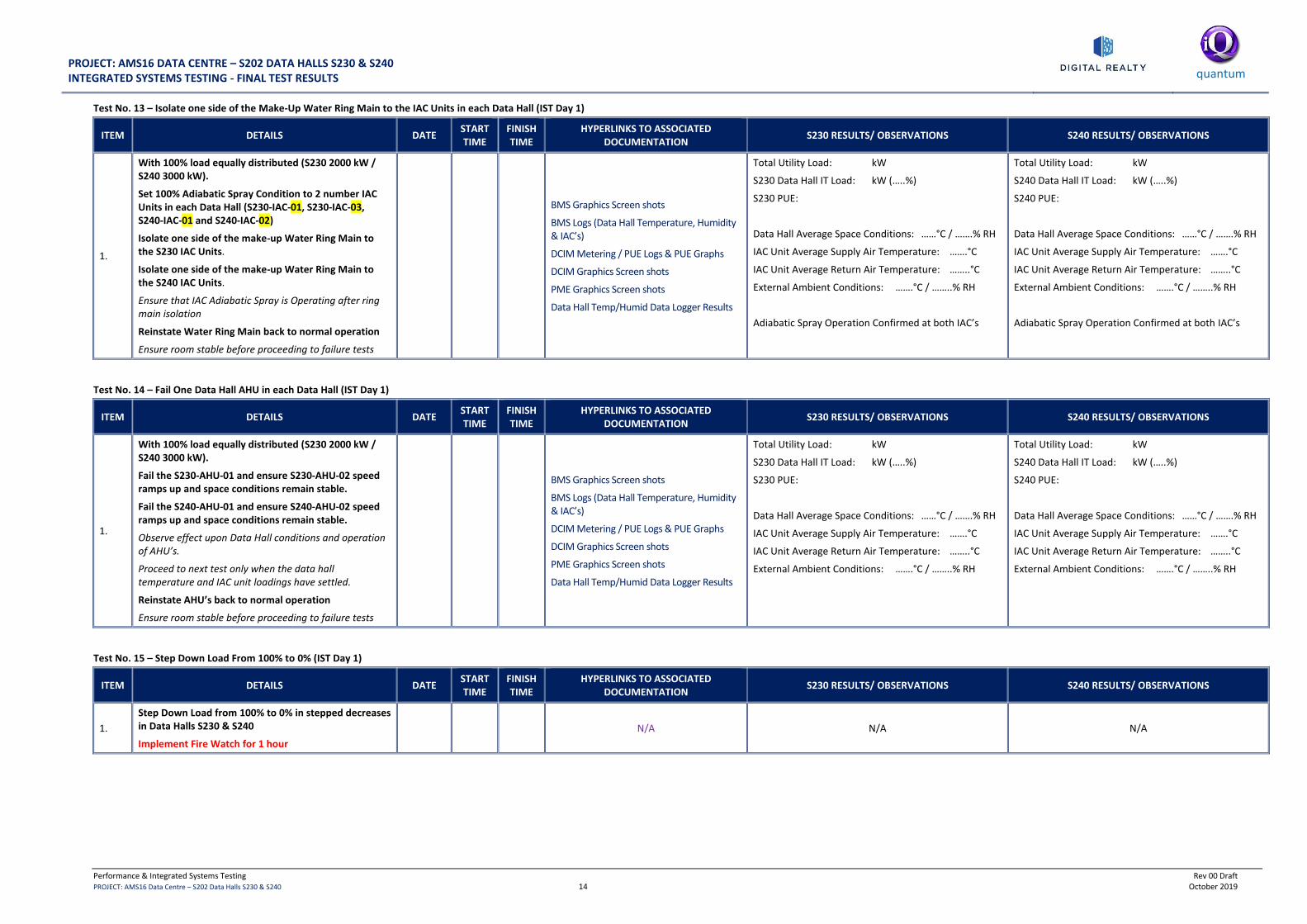
PROJECT: AMS16 DATA CENTRE – S202 DATA HALLS S230 & S240 INTEGRATED SYSTEMS TESTING - FINAL TEST RESULTS
quantum
Performance & Integrated Systems Testing Rev 00 Draft PROJECT: AMS16 Data Centre – S202 Data Halls S230 & S240 14 October 2019
Test No. 13 – Isolate one side of the Make-Up Water Ring Main to the IAC Units in each Data Hall (IST Day 1)
ITEM DETAILS DATE START TIME
FINISH TIME
HYPERLINKS TO ASSOCIATED DOCUMENTATION
S230 RESULTS/ OBSERVATIONS S240 RESULTS/ OBSERVATIONS
1.
With 100% load equally distributed (S230 2000 kW / S240 3000 kW).
Set 100% Adiabatic Spray Condition to 2 number IAC Units in each Data Hall (S230-IAC-01, S230-IAC-03, S240-IAC-01 and S240-IAC-02)
Isolate one side of the make-up Water Ring Main to the S230 IAC Units.
Isolate one side of the make-up Water Ring Main to the S240 IAC Units.
Ensure that IAC Adiabatic Spray is Operating after ring main isolation
Reinstate Water Ring Main back to normal operation
Ensure room stable before proceeding to failure tests
BMS Graphics Screen shots
BMS Logs (Data Hall Temperature, Humidity & IAC’s)
DCIM Metering / PUE Logs & PUE Graphs
DCIM Graphics Screen shots
PME Graphics Screen shots
Data Hall Temp/Humid Data Logger Results
Total Utility Load: kW
S230 Data Hall IT Load: kW (…..%)
S230 PUE:
Data Hall Average Space Conditions: ……°C / …….% RH
IAC Unit Average Supply Air Temperature: …….°C
IAC Unit Average Return Air Temperature: ……..°C
External Ambient Conditions: …….°C / ……..% RH
Adiabatic Spray Operation Confirmed at both IAC’s
Total Utility Load: kW
S240 Data Hall IT Load: kW (…..%)
S240 PUE:
Data Hall Average Space Conditions: ……°C / …….% RH
IAC Unit Average Supply Air Temperature: …….°C
IAC Unit Average Return Air Temperature: ……..°C
External Ambient Conditions: …….°C / ……..% RH
Adiabatic Spray Operation Confirmed at both IAC’s
Test No. 14 – Fail One Data Hall AHU in each Data Hall (IST Day 1)
ITEM DETAILS DATE START TIME
FINISH TIME
HYPERLINKS TO ASSOCIATED DOCUMENTATION
S230 RESULTS/ OBSERVATIONS S240 RESULTS/ OBSERVATIONS
1.
With 100% load equally distributed (S230 2000 kW / S240 3000 kW).
Fail the S230-AHU-01 and ensure S230-AHU-02 speed ramps up and space conditions remain stable.
Fail the S240-AHU-01 and ensure S240-AHU-02 speed ramps up and space conditions remain stable.
Observe effect upon Data Hall conditions and operation of AHU’s.
Proceed to next test only when the data hall temperature and IAC unit loadings have settled.
Reinstate AHU’s back to normal operation
Ensure room stable before proceeding to failure tests
BMS Graphics Screen shots
BMS Logs (Data Hall Temperature, Humidity & IAC’s)
DCIM Metering / PUE Logs & PUE Graphs
DCIM Graphics Screen shots
PME Graphics Screen shots
Data Hall Temp/Humid Data Logger Results
Total Utility Load: kW
S230 Data Hall IT Load: kW (…..%)
S230 PUE:
Data Hall Average Space Conditions: ……°C / …….% RH
IAC Unit Average Supply Air Temperature: …….°C
IAC Unit Average Return Air Temperature: ……..°C
External Ambient Conditions: …….°C / ……..% RH
Total Utility Load: kW
S240 Data Hall IT Load: kW (…..%)
S240 PUE:
Data Hall Average Space Conditions: ……°C / …….% RH
IAC Unit Average Supply Air Temperature: …….°C
IAC Unit Average Return Air Temperature: ……..°C
External Ambient Conditions: …….°C / ……..% RH
Test No. 15 – Step Down Load From 100% to 0% (IST Day 1)
ITEM DETAILS DATE START TIME
FINISH TIME
HYPERLINKS TO ASSOCIATED DOCUMENTATION
S230 RESULTS/ OBSERVATIONS S240 RESULTS/ OBSERVATIONS
1.
Step Down Load from 100% to 0% in stepped decreases in Data Halls S230 & S240
Implement Fire Watch for 1 hour
N/A N/A N/A

PROJECT: AMS16 DATA CENTRE – S202 DATA HALLS S230 & S240 INTEGRATED SYSTEMS TESTING - FINAL TEST RESULTS
quantum
Performance & Integrated Systems Testing Rev 00 Draft PROJECT: AMS16 Data Centre – S202 Data Halls S230 & S240 15 October 2019
6.0 ELECTRICAL RESILIENCE TOLERANCE TESTING PROCEDURES AT 100% LOAD (IST DAY 2)
Test No. 01 – Pre-Start Check (IST Day 2)
ITEM DETAILS DATE START TIME
FINISH TIME
HYPERLINKS TO ASSOCIATED DOCUMENTATION
S230 RESULTS / OBSERVATIONS S240 RESULTS/ OBSERVATIONS
1.
Ensure all systems are operational under automatic control and clear of any alarms prior to proceeding with any tests.
All plant and systems verified operational enabling test continuation.
N/A
Expected Result:
All plant verified as operational under automatic control.
No fault alarms on BMS (except IAC low Return Air Temp)
Expected Result:
All plant verified as operational under automatic control.
No fault alarms on BMS (except IAC low Return Air Temp)
Test No. 02 – Data Hall Normalisation Period (IST Day 2)
ITEM DETAILS DATE START TIME
FINISH TIME
HYPERLINKS TO ASSOCIATED DOCUMENTATION
S230 RESULTS/ OBSERVATIONS S240 RESULTS/ OBSERVATIONS
1.
All systems operational with no load.
Ensure room is stable for a period of time before taking load and temperature measurements. Proceed only once
measurements are complete.
BMS Graphics Screen shots
BMS Logs (Data Hall Temperature, Humidity & IAC’s)
DCIM Metering / PUE Logs & PUE Graphs
DCIM Graphics Screen shots
PME Graphics Screen shots
Data Hall Temp/Humid Data Logger Results
Total Utility Load: kW
Data Hall IT Load: 0 kW (0%)
No Heat Load applied.
Total Utility Load: kW
Data Hall IT Load: 0 kW (0%)
No Heat Load applied.
Test No. 03– Load Data Halls to 100% (IST Day 2)
ITEM DETAILS DATE START TIME
FINISH TIME
HYPERLINKS TO ASSOCIATED DOCUMENTATION S230 – S240 RESULTS / OBSERVATIONS
1.
Apply 100% load (2000 kW) equally distributed in Data Hall S230.
Ensure Data Hall is stable for a period of time before taking load and temperature measurements. Proceed to failure tests only once measurements
are complete.
Apply 100% load (3000 kW) equally distributed in Data Hall S240.
Ensure Data Hall is stable for a period of time before taking load and temperature measurements.
Proceed to failure tests only once measurements are complete.
BMS Graphics Screen shots
BMS Logs (Data Hall Temperature, Humidity & IAC’s)
DCIM Metering / PUE Logs & PUE Graphs
DCIM Graphics Screen shots
PME Graphics Screen shots & Logs
Data Hall Temp/Humid Data Logger Results
LV Board HMI Graphic Screen shots
UPS Output Meters: MV Feeder Meters
A ………….kW Ring A ………….kW
B ………….kW Ring B ………….kW
C ………….kW Ring C ………….kW
D ………….kW Ring D ………….kW
E ………….kW Ring E ………….kW
Total load:……….kW Total: ………….kW
External Ambient Conditions: …… °C / ……..% RH
S230: Average Data Hall Conditions: 0C / % RH
S230 PUE:
S240: Average Data Hall Conditions: 0C / % RH
S240 PUE:

PROJECT: AMS16 DATA CENTRE – S202 DATA HALLS S230 & S240 INTEGRATED SYSTEMS TESTING - FINAL TEST RESULTS
quantum
Performance & Integrated Systems Testing Rev 00 Draft PROJECT: AMS16 Data Centre – S202 Data Halls S230 & S240 16 October 2019
Test No. 04 – Failure of MV A Supply (IST Day 2)
ITEM DETAILS DATE START TIME
FINISH TIME
HYPERLINKS TO ASSOCIATED DOCUMENTATION S230 – S240 RESULTS / OBSERVATIONS
1.
Fail MV A Supply by opening Liander feeder supply A
Ensure DMC is set for manually instigated restoration in open transition mode
Ensure that there are no ATS changeovers in this time
There should be no manual intervention during anytime during the test.
Proceed to next test only when the data hall temperature & humidity have settled.
Generators should start and the DMC will move the load onto Supply B. Following successful transfer generators will stop
BMS Graphics Screen shots
BMS Logs (Data Hall Temperature, Humidity & IAC’s)
DCIM Metering / PUE Logs & PUE Graphs
DCIM Graphics Screen shots
PME Graphics Screen shots & Logs
Data Hall Temp/Humid Data Logger Results
LV Board HMI Graphic Screen shots
UPS Output Meters: MV Feeder Meters
A ………….kW Ring A ………….kW
B ………….kW Ring B ………….kW
C ………….kW Ring C ………….kW
D ………….kW Ring D ………….kW
E ………….kW Ring E ………….kW
F ………….kW Ring F ………….kW
Total load:……….kW Total: ………….kW
External Ambient Conditions: ……. °C / ……..% RH
S230: Average Data Hall Conditions: 0C / % RH
S240: Average Data Hall Conditions: 0C / % RH
Test No. 05 – Reinstatement of MV A Supply (IST Day 2)
ITEM DETAILS DATE START TIME
FINISH TIME
HYPERLINKS TO ASSOCIATED DOCUMENTATION S230 – S240 RESULTS / OBSERVATIONS
1.
Reinstate MV A Supply by closing Liander feeder supply A
Instigate restoration on the DMC
Ensure that there are no ATS changeovers in this time
There should be no manual intervention during anytime during the test.
Proceed to next test only when the data hall temperature & humidity have settled.
CHECK BATTERY TIME REMINING ON THE UPS UNITS.
IT MAY BE NECESSARY TO POSTPONE TEST No.06 FOR 12/24 HOURS TO ALLOW BATTERIES TO RECHARGE
BMS Graphics Screen shots
BMS Logs (Data Hall Temperature, Humidity & IAC’s)
DCIM Metering / PUE Logs & PUE Graphs
DCIM Graphics Screen shots
PME Graphics Screen shots & Logs
Data Hall Temp/Humid Data Logger Results
LV Board HMI Graphic Screen shots
UPS Output Meters: MV Feeder Meters
A ………….kW Ring A ………….kW
B ………….kW Ring B ………….kW
C ………….kW Ring C ………….kW
D ………….kW Ring D ………….kW
E ………….kW Ring E ………….kW
F ………….kW Ring F ………….kW
Total load:……….kW Total: ………….kW
External Ambient Conditions: ……. °C / ……..% RH
S230: Average Data Hall Conditions: 0C / % RH
S240: Average Data Hall Conditions: 0C / % RH

PROJECT: AMS16 DATA CENTRE – S202 DATA HALLS S230 & S240 INTEGRATED SYSTEMS TESTING - FINAL TEST RESULTS
quantum
Performance & Integrated Systems Testing Rev 00 Draft PROJECT: AMS16 Data Centre – S202 Data Halls S230 & S240 17 October 2019
Test No. 06 – Failure of MV B Supply (IST Day 2)
ITEM DETAILS DATE START TIME
FINISH TIME
HYPERLINKS TO ASSOCIATED DOCUMENTATION S230 – S240 RESULTS / OBSERVATIONS
1.
Fail MV B Supply by opening Liander feeder supply B
Ensure DMC is set for manually instigated restoration in open transition mode
Ensure that there are no ATS changeovers in this time
There should be no manual intervention during anytime during the test.
Proceed to next test only when the data hall temperature & humidity have settled.
Generators should start and the DMC will move the load onto Supply B. Following successful transfer generators will stop
BMS Graphics Screen shots
BMS Logs (Data Hall Temperature, Humidity & IAC’s)
DCIM Metering / PUE Logs & PUE Graphs
DCIM Graphics Screen shots
PME Graphics Screen shots & Logs
Data Hall Temp/Humid Data Logger Results
LV Board HMI Graphic Screen shots
UPS Output Meters: MV Feeder Meters
A ………….kW Ring A ………….kW
B ………….kW Ring B ………….kW
C ………….kW Ring C ………….kW
D ………….kW Ring D ………….kW
E ………….kW Ring E ………….kW
F ………….kW Ring F ………….kW
Total load:……….kW Total: ………….kW
External Ambient Conditions: ……. °C / ……..% RH
S230: Average Data Hall Conditions: 0C / % RH
S240: Average Data Hall Conditions: 0C / % RH
Test No. 07 – Reinstatement of MV B Supply (IST Day 2)
ITEM DETAILS DATE START TIME
FINISH TIME
HYPERLINKS TO ASSOCIATED DOCUMENTATION S230 – S240 RESULTS / OBSERVATIONS
1.
Reinstate MV B Supply by closing Liander feeder supply B
Instigate restoration on the DMC
Ensure that there are no ATS changeovers in this time
There should be no manual intervention during anytime during the test.
Proceed to next test only when the data hall temperature & humidity have settled.
CHECK BATTERY TIME REMINING ON THE UPS UNITS.
IT MAY BE NECESSARY TO POSTPONE TEST No.08 FOR 12/24 HOURS TO ALLOW BATTERIES TO RECHARGE
BMS Graphics Screen shots
BMS Logs (Data Hall Temperature, Humidity & IAC’s)
DCIM Metering / PUE Logs & PUE Graphs
DCIM Graphics Screen shots
PME Graphics Screen shots & Logs
Data Hall Temp/Humid Data Logger Results
LV Board HMI Graphic Screen shots
UPS Output Meters: MV Feeder Meters
A ………….kW Ring A ………….kW
B ………….kW Ring B ………….kW
C ………….kW Ring C ………….kW
D ………….kW Ring D ………….kW
E ………….kW Ring E ………….kW
F ………….kW Ring F ………….kW
Total load:……….kW Total: ………….kW
External Ambient Conditions: ……. °C / ……..% RH
S230: Average Data Hall Conditions: 0C / % RH
S240: Average Data Hall Conditions: 0C / % RH

PROJECT: AMS16 DATA CENTRE – S202 DATA HALLS S230 & S240 INTEGRATED SYSTEMS TESTING - FINAL TEST RESULTS
quantum
Performance & Integrated Systems Testing Rev 00 Draft PROJECT: AMS16 Data Centre – S202 Data Halls S230 & S240 18 October 2019
Test No. 08 – Failure of MV A and B Supplies [OPEN TRANSITION RESTORATION] (IST Day 2)
ITEM DETAILS DATE START TIME
FINISH TIME
HYPERLINKS TO ASSOCIATED DOCUMENTATION S230 – S240 RESULTS / OBSERVATIONS
1.
Fail MV A and B Supply by opening Liander feeder supplies A and B
Ensure DMC is set for manually instigated restoration in open transition mode
Ensure that there are no ATS changeovers in this time
There should be no manual intervention during anytime during the test.
Proceed to next test only when the data hall temperature & humidity have settled.
Generators should start and the DMC will restore site supply to generator operation
BMS Graphics Screen shots
BMS Logs (Data Hall Temperature, Humidity & IAC’s)
DCIM Metering / PUE Logs & PUE Graphs
DCIM Graphics Screen shots
PME Graphics Screen shots & Logs
Data Hall Temp/Humid Data Logger Results
LV Board HMI Graphic Screen shots
UPS Output Meters: MV Feeder Meters
A ………….kW Ring A ………….kW
B ………….kW Ring B ………….kW
C ………….kW Ring C ………….kW
D ………….kW Ring D ………….kW
E ………….kW Ring E ………….kW
F ………….kW Ring F ………….kW
Total load:……….kW Total: ………….kW
External Ambient Conditions: ……. °C / ……..% RH
S230: Average Data Hall Conditions: 0C / % RH
S240: Average Data Hall Conditions: 0C / % RH
Test No. 09 – Reinstatement of MV A and B Supplies [OPEN TRANSITION RESTORATION] (IST Day 2)
ITEM DETAILS DATE START TIME
FINISH TIME
HYPERLINKS TO ASSOCIATED DOCUMENTATION S230 – S240 RESULTS / OBSERVATIONS
1.
Reinstate MV A and B Supply by closing Liander feeder supplies A and B
Instigate restoration on the DMC
Ensure that there are no ATS changeovers in this time
There should be no manual intervention during anytime during the test.
Proceed to next test only when the data hall temperature & humidity have settled.
CHECK BATTERY TIME REMINING ON THE UPS UNITS.
IT MAY BE NECESSARY TO POSTPONE TEST No.10 FOR 12/24 HOURS TO ALLOW BATTERIES TO RECHARGE
BMS Graphics Screen shots
BMS Logs (Data Hall Temperature, Humidity & IAC’s)
DCIM Metering / PUE Logs & PUE Graphs
DCIM Graphics Screen shots
PME Graphics Screen shots & Logs
Data Hall Temp/Humid Data Logger Results
LV Board HMI Graphic Screen shots
UPS Output Meters: MV Feeder Meters
A ………….kW Ring A ………….kW
B ………….kW Ring B ………….kW
C ………….kW Ring C ………….kW
D ………….kW Ring D ………….kW
E ………….kW Ring E ………….kW
F ………….kW Ring F ………….kW
Total load:……….kW Total: ………….kW
External Ambient Conditions: ……. °C / ……..% RH
S230: Average Data Hall Conditions: 0C / % RH
S240: Average Data Hall Conditions: 0C / % RH

PROJECT: AMS16 DATA CENTRE – S202 DATA HALLS S230 & S240 INTEGRATED SYSTEMS TESTING - FINAL TEST RESULTS
quantum
Performance & Integrated Systems Testing Rev 00 Draft PROJECT: AMS16 Data Centre – S202 Data Halls S230 & S240 19 October 2019
Test No. 10 – Failure of MV A and B Supplies [CLOSED TRANSITION RESTORATION] (IST Day 2)
ITEM DETAILS DATE START TIME
FINISH TIME
HYPERLINKS TO ASSOCIATED DOCUMENTATION S230 – S240 RESULTS / OBSERVATIONS
1.
Fail MV A and B Supply by opening Liander feeder supplies A and B
Ensure DMC is set for manually instigated restoration in closed transition mode
Ensure that there are no ATS changeovers in this time
There should be no manual intervention during anytime during the test.
Proceed to next test only when the data hall temperature & humidity have settled.
Generators should start and the DMC will restore site supply to generator operation
BMS Graphics Screen shots
BMS Logs (Data Hall Temperature, Humidity & IAC’s)
DCIM Metering / PUE Logs & PUE Graphs
DCIM Graphics Screen shots
PME Graphics Screen shots & Logs
Data Hall Temp/Humid Data Logger Results
LV Board HMI Graphic Screen shots
UPS Output Meters: MV Feeder Meters
A ………….kW Ring A ………….kW
B ………….kW Ring B ………….kW
C ………….kW Ring C ………….kW
D ………….kW Ring D ………….kW
E ………….kW Ring E ………….kW
F ………….kW Ring F ………….kW
Total load:……….kW Total: ………….kW
External Ambient Conditions: …….°C / ……..% RH
S150: Average Data Hall Conditions: 0C / % RH
S150 PUE:
S160: Average Data Hall Conditions: 0C / % RH
S160 PUE:
Test No. 11 – Reinstatement of MV A and B Supplies [CLOSED TRANSITION RESTORATION] (IST Day 2)
ITEM DETAILS DATE START TIME
FINISH TIME
HYPERLINKS TO ASSOCIATED DOCUMENTATION S230 – S240 RESULTS / OBSERVATIONS
1.
Reinstate MV A and B Supply by closing Liander feeder supplies A and B
Instigate restoration on the DMC
Ensure that there are no ATS changeovers in this time
There should be no manual intervention during anytime during the test.
Proceed to next test only when the data hall temperature & humidity have settled.
BMS Graphics Screen shots
BMS Logs (Data Hall Temperature, Humidity & IAC’s)
DCIM Metering / PUE Logs & PUE Graphs
DCIM Graphics Screen shots
PME Graphics Screen shots & Logs
Data Hall Temp/Humid Data Logger Results
LV Board HMI Graphic Screen shots
UPS Output Meters: MV Feeder Meters
A ………….kW Ring A ………….kW
B ………….kW Ring B ………….kW
C ………….kW Ring C ………….kW
D ………….kW Ring D ………….kW
E ………….kW Ring E ………….kW
F ………….kW Ring F ………….kW
Total load:……….kW Total: ………….kW
External Ambient Conditions: …….°C / ……..% RH
S150: Average Data Hall Conditions: 0C / % RH
S150 PUE:
S160: Average Data Hall Conditions: 0C / % RH
S160 PUE:
Test No. 12 – Step Down Load From 100% to 0% (IST Day 2)
ITEM DETAILS DATE START TIME
FINISH TIME
HYPERLINKS TO ASSOCIATED DOCUMENTATION
S230 RESULTS/ OBSERVATIONS S240 RESULTS/ OBSERVATIONS
1.
Step Down Load from 100% to 0% in stepped decreases in Data Halls S230 & S240
Implement Fire Watch for 1 hour
N/A N/A N/A
PROJECT: AMS16 DATA CENTRE – S202 DATA HALLS S230 & S240 INTEGRATED SYSTEMS TESTING - FINAL TEST RESULTS
quantum
Performance & Integrated Systems Testing Rev 00 Draft PROJECT: AMS16 Data Centre – S202 Data Halls S230 & S240 20 October 2019
8.0 PHOTOGRAPHS OF HOT AISLE CONTAINMENT SIMULATION