Embed Size (px)
Citation preview

D3.1 Specifications of HW Architecture and Prototype
Page 1 of 35
This document is Confidential, and was produced under the ECOSCALE project (EC contract 671632).
Project No: 671632
D3.1 Specifications of HW Architecture and Prototype
April 30,2016
Abstract:
This deliverable describes the architecture of the ECOSCALE platform focusing on the components of the
ECOSCALE Compute Node and their interfaces. The document explains in detail how the ECOSCALE Workers can
share reconfigurable resources and how OpenCL kernels can be executed on the platform. Finally, the document
describes the ECOSCALE prototype explaining that the ExaNeSt prototype card will be used.
Document Manager
Iakovos Mavroidis TSI
Document Id N°: ECOSCALE_D3.1 Version: 1.17 Date: 27/05/2016
Filename: ECOSCALE_D3.1_v1.17.docx
Confidentiality
This document contains proprietary and confidential material of certain ECOSCALE contractors, and may
not be reproduced, copied, or disclosed without appropriate permission. The commercial use of any
information contained in this document may require a license from the proprietor of that information

D3.1 Specifications of HW Architecture and Prototype
Page 2 of 35
This document is Confidential, and was produced under the ECOSCALE project (EC contract 671632).
The ECOSCALE Consortium consists of the following partners:
Participant no. Participant organisation names short name Country
P1 (Coordinator) Telecommunication Systems Institute TSI Greece
P2 Queen's University Belfast QUB United
Kingdom
P3 STMicroelectronics STM France
P4 Acciona ACC Spain
P5 University of Manchester MAN United
Kingdom
P6 Politecnico di Torino POLITO Italy
P7 Chalmers University of Technology CHAL Sweden
P8 Synelixis SYN Greece
The information in this document is provided “as is” and no guarantee or warranty is given that the
information is fit for any particular purpose. The user thereof uses the information at its sole risk and
liability.
Revision history
Version Author Notes Date
1.0 Iakovos Mavroidis Table of Contents 21/04/2016
1.1 Marcello Coppola Table of Contents update
1.2 Paul Harvey Questions and Comments 29/04/2016
1.3 Luciano Lavagno Global edit and section 3.3 02/05/2016
1.3 Vassilis Papaefstathiou Added section 3.1 04/05/2016
1.3 Joel Svensson Minor edits of typos 05/05/2016
1.4 Ignacio Munárriz,
Manuel Palomino
Questions and Comments 06/05/2016
1.5 Iakovos Mavroidis
Kostas Georgopoulos
Added summary, introduction, and section 4.1 07/05/2016
1.6 Joel Svensson Minor edits 09/05/2016
1.7 Paul Harvey Questions and Comments 09/05/2016
1.7 I. Sourdis Comments added in Section 3 10/05/2016
1.8 Iakovos Mavroidis Updates on Section 4.2 11/05/2016
1.8 Vassilis Papaefstathiou Edits on Section 3.1 11/05/2016
1.10 Edson Horta Internal Review 17/05/2016
1.11 Paul Harvey Internal Review 19/05/2016
1.12 Marcello Coppola Internal Review 20/05/2016
1.13 Marcello Coppola Removing the edits in Section 2 20/05/2016
1.14 Yannis Papaefstathiou Internal Review 23/05/2016
1.15 Marcello Coppola,
Michael Soulie
STNoC improvements according to the comments 24/05/2016
1.16 Kostas Georgopoulos Document updating, added figure caption on page
26, eliminated double spaces
25/05/2016
1.17 Vassilis Papaefstathiou Final edits 27/05/2016

D3.1 Specifications of HW Architecture and Prototype
Page 3 of 35
This document is Confidential, and was produced under the ECOSCALE project (EC contract 671632).
Contents
1. Introduction .............................................................................................................................................6
1.1 Glossary of Acronyms ......................................................................................................................6
2. The ECOSCALE Architecture .....................................................................................................................8
2.1 The UNIMEM Architecture in ECOSCALE ...................................................................................... 11
2.2 The UNILOGIC Architecture .......................................................................................................... 14
3. Hardware Virtualization Support .......................................................................................................... 16
3.1 HW Virtualization Block ................................................................................................................ 17
3.2 User-space Direct Accesses ........................................................................................................... 23
3.3 Reconfigurable Accelerator Block ................................................................................................. 25
4. Interconnection..................................................................................................................................... 26
4.1 Interconnection protocols ............................................................................................................ 26
4.2 AMBA ............................................................................................................................................ 26
4.3 Network on chip (NOC) ................................................................................................................. 26
4.4 STNoC overview ............................................................................................................................ 27
4.5 STNoC architecture ....................................................................................................................... 27
4.6 STNoC memory map and services ................................................................................................ 28
5 Hardware Platform ............................................................................................................................... 29
5.1 ECOSCALE Prototypes ................................................................................................................... 32
5.2 Final Hardware Prototype ............................................................................................................. 32
6 Conclusions ........................................................................................................................................... 34

D3.1 Specifications of HW Architecture and Prototype
Page 4 of 35
This document is Confidential, and was produced under the ECOSCALE project (EC contract 671632).
List of Figures
Figure 1: High-radix partitioning for HPC applications ..................................................................................8
Figure 2: The ECSOCALE Compute Node architecture .................................................................................9
Figure 3: Block diagram of ECOSCALE Worker ........................................................................................ 10
Figure 4: Accesses in the external “window” of the local address space are translated to global memory
access. ........................................................................................................................................................... 12
Figure 5: Address mapping of Juno. The yellow region can be used as the external “window” in order to
perform accessed in the global address space. .............................................................................................. 12
Figure 6: Partitioning of 256-GByte window into 16 regions, each one corresponding to a Worker in the
PGAS. ........................................................................................................................................................... 13
Figure 7: Worker 0 borrows a remote memory page from Worker 1. This page is cached and accessed only
by Worker 0. ................................................................................................................................................. 13
Figure 8: Red page is shared between Worker 0 and Worker 1.All accesses pass through the cache of
Worker 1. ...................................................................................................................................................... 14
Figure 9: Worker 0 can directly send a command to the Reconfigurable Block of Worker 1 and the
Reconfigurable Block can directly access the memory of Worker 0. ........................................................... 15
Figure 10. The Virtualization block accepts several calls of the same kernel and schedules their work
groups to the reconfigurable accelerator, which in turn can execute multiple work groups in parallel. ....... 17
Figure 11: A generic OpenCL implementation of SAXPY Level-1 BLAS Routine .................................... 18
Figure 12: Splitting of OpenCLNDRangeKernel into work-groups ............................................................. 18
Figure 13: Pseudo-code for the generation of work-groups from anNDRangeKernel call........................... 19
Figure 14: Scheduling Work-Groups onto the available HW functional units ............................................. 20
Figure 15: Scheduling work-groups from multiple applications on the available HW functional units ....... 21
Figure 16: Virtual, Physical and Global Address Spaces. ............................................................................ 23
Figure 17: Address Translation Table used to translate VA’s of the arguments of a workgroup to PA’s. ... 24
Figure 18: The NoC paradigm ...................................................................................................................... 27
Figure 19: Example STNoC architecture. ..................................................................................................... 28
Figure 20: Zynq Ultrascale+ MPSoC top-level block diagram .................................................................... 30
Figure 21: Global system address map ......................................................................................................... 31
Figure 22: ExaNeSt prototype cards interconnected in 2D-torus topology to form a Compute Node. ........ 33

D3.1 Specifications of HW Architecture and Prototype
Page 5 of 35
This document is Confidential, and was produced under the ECOSCALE project (EC contract 671632).
Executive Summary
This deliverable contains a detailed description of the information related to the specifications of the
hardware architecture of the ECOSCALE system as well as the ECOSCALE demonstration platform.
Specifically, this document separates into key sections and sub-sections the significant elements that are
essential to the two aforementioned objects. Hence, the specifications defined in this deliverable are as
follows.
First, the document presents the specifications related to the ECOSCALE hardware architecture and,
specifically, those that have to do with i) how the existing UNIMEM architecture is adapted to the
ECOSCALE context and ii) the proposed novel UNILOGIC architecture, which will be defined, designed
and implemented within the ECOSCALE project.
Secondly, the UNIMEM and UNILOGIC architectures can effectively be integrated within the
ECOSCALE system only if both support a set of specifications which cover the required virtualisation
support. Specifically, and within the context of the overall system, the virtualisation support specifications
are defined in relation to three key sub-elements, i.e. the HW Virtualisation block, the user-space direct
accesses and, finally, the reconfigurable accelerator block.
Following the virtualisation support specifications are the specifications of the ECOSCALE system
interconnections, which are also very important. In this context, the information is split into i) the
interconnection protocols of interest, ii) an overview of specifications for the AXI bus protocol that shall
also be extensively used in the system, and iii) the specifications of STNoC which is a novel architecture
for industrial on-chip communication network infrastructures.
Finally, this document presents the specifications of the actual hardware platform that is to host the
complete ECOSCALE system. This is comprised of i) an initial simpler development card and ii) the actual
hardware prototype; the initial specifications for both are presented in the final sections of this document.
The former refers to the hardware specifications of the core of the initial demonstration platforms whereas
the latter refers to the hardware specifications of the hardware system that will be implemented within the
ExaNest project and which will be used for the full demonstration of the ECOSCALE approach.

D3.1 Specifications of HW Architecture and Prototype
Page 6 of 35
This document is Confidential, and was produced under the ECOSCALE project (EC contract 671632).
1. Introduction This document will address an important aspect of the ECOSCALE project, namely that of defining the
architectural specifications of the ECOSCALE system and its sub-elements. In other words, the
specifications of the high-level node hardware architecture including the CPUs, the reconfigurable devices,
the memory, and the I/O sub-systems will be derived. The specifications are mainly based on the exact
requirements of the two ECOSCALE real-world applications and they include those of the hardware
prototype that will be utilized in the evaluation of the end-platform when executing the real-world
applications.
It is a fundamental need to have a clearly defined set of specifications for the ECOSCALE system prior to
actually commencing with its development. Here the fundamental specifications related to key elements of
this system are presented in the following order and in their respective sections and sub-sections. First, the
overall ECOSCALE architecture is presented for context, and then the specifications related to the
UNIMEM and UNILOGIC architectures are presented. The UNIMEM architecture is a pre-existing
technology that has been adapted to the context of the ECOSCALE requirements, whereas UNILOGIC is a
novel technology to be developed within ECOSCALE. In order for both to materialise, a set of
specification are laid out in Section 2.
Subsequently, the ECOSCALE system will comprise of various sub-components and sub-elements such as
the hardware accelerator blocks. The integration of such components within the UNIMEM/UNILOGIC
architecture raise several issues regarding the memory addressing, therefore, an important elementof the
ECOSCALE system is that of sharing reconfigurable resources in hardware (hardware-assisted
virtualisation). Section 3 addresses the virtualisation support specifications specifically in relation to i) the
hardware virtualisation block, ii) user-space direct accesses and iii) the reconfigurable accelerator blocks.
Of equal importance is the set of specifications related to the ECOSCALE system interconnects and this is
addressed in Section 4. This refers to the interconnect protocols that will be used by the system such as the
AMBA AXI4 communication protocol and the STNoC programmable system-on-chip communication
network.
Finally, the ECOSCALE system is to be implemented in two different stages, first a demonstration
platform that may consist of off-the-shelf development boards and second ata hardware prototype
developed and manufactured within the context of the sister project ExaNest which will specifically
address the requirements/specifications of ECOSCALE; strictly hardware-related specifications related to
those two types of platforms are presented in Section 5.
1.1 Glossary of Acronyms
Acronym Definition
AMBA Advanced Microprocessor Bus Architecture
AXI Advanced eXtensible Interface
D Deliverable
EC European Commission
GA Global Address
GPU Graphics Processing Unit
HCP High Performance Computing
HLS High Level Synthesis

D3.1 Specifications of HW Architecture and Prototype
Page 7 of 35
This document is Confidential, and was produced under the ECOSCALE project (EC contract 671632).
MPI Message Passing Interface
PA Physical Address
WG Workgroup
WP Work-Package

D3.1 Specifications of HW Architecture and Prototype
Page 8 of 35
This document is Confidential, and was produced under the ECOSCALE project (EC contract 671632).
2. The ECOSCALE Architecture
This section offers an initial description of the ECOSCALE architecture, i.e. it offers a high-level
description of the system architecture. It therefore serves as a stepping stone for the material that follows in
later sections. These sections extensively analyse all the various sub-elements that make up the complete
system.
Overall, the ECOSCALE architecture will expand a memory technology known as UNIMEM (introduced
in the Euroserver project1 and described in more detail in Section 2.1) by providing the systems software
with the option to move tasks and processes closer to data instead of moving data around, significantly
reducing the data traffic and related energy consumption. In order to expand this approach within the
ECOSCALE project, a novel Partitioned Global Address Space (PGAS) memory system will be developed
which will be globally accessible from the general-purpose CPU cores as well as ECOSCALE’s
UNILOGIC architecture (described in more detail in Section 2.2) through regular loads and stores.
The UNILOGIC architecture, developed as part of this project, will operate within an environment of
virtualized hardware accelerators which will allow for the parallel execution of either different applications
and/or different parts of the same application. As a result, the ECOSCALE PGAS system shall extend the
UNIMEM memory architecture through a shared partitioned address space, while efficiently extending the
notion of global cache coherence so as to improve energy efficiency and scalability.
Figure 1: High-radix partitioning for HPC applications
Subsequently, the system architecture will be mainly comprised of CPUs, memory units and reconfigurable
blocks (i.e. FPGA-based accelerators as explained below) all implemented to operate in a highly parallel
manner. Driven by the characteristics and trends of future High Performance Computing (HPC)
applications and following the high-radix partitioning of an HPC application shown in Figure 1, the
proposed architecture partitions the hardware resources hierarchically, i.e. CPUs, reconfigurable logic,
memories, SSDs etc., into several interconnected sub-systems (corresponding to the PGAS partitions of the
application) which we call Compute Nodes; the Compute Nodes are further partitioned into several, what
we call, Worker nodes, each of which consists of a multi-core CPU tightly coupled with a memory and a
1http://www.euroserver-project.eu/

D3.1 Specifications of HW Architecture and Prototype
Page 9 of 35
This document is Confidential, and was produced under the ECOSCALE project (EC contract 671632).
reconfigurable block; the capabilities and characteristics of each of those Nodes are analytically described
in the following paragraphs. The number of Workers per Compute Node (i.e. the size of a PGAS partition)
depends on the physical structure of the platform.
Thus, one Compute Node, Figure 2, creates an entire and independent PGAS system (or part of a system)
and each one includes several Worker nodes; this approach offers the following:
UNIMEM: a shared partitioned global address space that allows Worker nodes to communicate
via regular loads and stores without global cache coherence and
UNILOGIC: shared partitioned reconfigurable resources that share the UNIMEM space which
comprises only of software tasks.
Figure 2: The ECSOCALE Compute Node architecture
The benefit of the ECOSCALE architecture is that it overcomes limitations exhibited by other existing
architectures that either require a conventional global cache coherence mechanism, which simply cannot
scale, or support only DMA operations, which are not efficient for small data transfers such as messages to
synchronize remote threads or for configuring a remote peripheral. UNILOGIC supports both bulk DMA
transfers and direct load/store instructions between Workers.
The proposed HPC architecture, where i) each Compute Node is a PGAS sub-system providing a shared
address space and reconfigurable acceleration logic, and ii) MPI is used for communication between
Compute Nodes following the application topology, is shown in Figure 2. It consists of several Worker
nodes communicating through a multi-layer interconnection. The actual number of Workers inside a
Compute Node depends on the integration capabilities of future technologies. The ECOSCALE prototype
is expected to support 64 Workers (16 daughter cards x 4 FPGAs) per Compute Node as described in
Section 5.2. Each Worker is an independent computing unit that can execute, fork, and join tasks or threads
of an HPC application in-parallel with the other Workers. It includes a multi-core CPU, a reconfigurable
block and an off-chip DRAM memory, all communicating through a cache-coherent L0 interconnect.
Furthermore, the communication and synchronization between the Workers is performed through a multi-
layer non-coherent interconnection, which allows load and store commands, DMA operations, interrupts,
and synchronization between the Workers of a Compute Node (following the UNIMEM architecture
described in Section 2.1). The Compute Nodes are PGAS sub-systems that correspond to the application's
PGAS-based partitions shown in Figure 1.

D3.1 Specifications of HW Architecture and Prototype
Page 10 of 35
This document is Confidential, and was produced under the ECOSCALE project (EC contract 671632).
In order to match the application logical topology of Figure 1, the Compute Nodes are connected through a
multi-layer interconnection network and communicate with MPI. The ExaNeSt project2 focuses on this
multi-layer interconnection topology while ECOSCALE focuses on a single Compute Node. As we explain
in the next Sections there is close collaboration between these two projects.
Figure 3: Block diagram of ECOSCALE Worker
The communication overhead between a CPU and a hardware accelerator, i.e. the Reconfigurable Block
inside a Worker node, is one of the most crucial challenges. A few years ago, only explicit memory
transfers between the host memory and the accelerator's memory were supported, like in a GPU. Recent
technological advances allow the integration of the host CPU and hardware accelerators on the same chip,
and thus hardware accelerators can now directly access the host memory. Such a typical ARM-based
system is depicted on the left of Figure 3. However, there are still important limitations, described below,
that are tackled by the ECOSCALE system.
In the state-of-the-art architecture depicted in Figure 3, the ARM Cache Coherent Interconnect supports
two types of coherent ports in order to provide hardware coherency to the whole system: i) ACE ports,
which can be used by masters containing and sharing caches, such as a processor, and ii) ACE-lite ports,
which can be used by masters that have private caches/memory. ACE-lite ports allow the masters to access
the shared caches of other masters and they are traditionally used for hardware accelerators such as GPUs
and FPGAs, shown in the figure.
On the right side of Figure 3, the block diagram of an ECOSCALE Worker node is shown. The proposed
architecture will extend such a typical architecture as follows. Accelerator blocks act as what is known in
UNIMEM as a Unit of Compute, and hence they can interface directly with any other UNIMEM Unit of
Compute where each unit caches its local data coherently. Each accelerator can also cache its local data and
likewise provide coherent access from remote UNIMEM units.
Virtualization enables multiple applications or threads of an application to share a single multi-core CPU in
order to maximize the utilization of the CPU resources and hence reduce power consumption. Similarly,
2http://www.exanest.eu/

D3.1 Specifications of HW Architecture and Prototype
Page 11 of 35
This document is Confidential, and was produced under the ECOSCALE project (EC contract 671632).
our architecture will support coarse-grain time-sharing of the reconfigurable resources through partial
runtime reconfiguration (implemented by the HW Context Switching block as described in D3.2).
Moreover, it will support fine-grain sharing of those FPGA resources, where a function implemented in
hardware can be “called” by different tasks or threads of an HPC application in parallel, through the HW
Virtualization block shown in Figure 3 (see also Section 3). The Virtualization block and the HLS tool
provide a mechanism to execute multiple function calls in a fully pipelined fashion.
Sharing of the limited reconfigurable resources between Workers is very important. Thus, within a
Compute Node, any Worker can access any Reconfigurable block (even remote blocks that belong to other
Workers) through the multi-layer interconnect (L0 and L1 interconnects) shown in Figure 2. Moreover, the
L0 Interconnect in this system provides two external ports: one ACE-lite port and one standard
AXI(connection to L1 interconnect of Figure 3) that can be used by remote Reconfigurable blocks to make
coherent accesses. However, since this is not an ACE port (no snooping protocol is supported) the remote
Reconfigurable block should flush its data cache when execution is finished or disable its data cache (and
would not be as efficient as a local one).
2.1 The UNIMEM Architecture in ECOSCALE
The UNIMEM architecture3 aims to provide a scalable distributed system solution enabling direct remote
memory accesses and shared memory. Toward this end the architecture offers a) a global address space and
b) remote coherent accesses. Both are described below.
Global Address Space: The UNIMEM architecture can be deployed in a system consisting of several
"coherence islands", where a coherence island includes one or more processors, a cache coherent memory,
various peripherals and an external port for remote accesses. All accesses inside the coherence island are
cache coherent. In the ECOSCALE architecture, a "Worker" is one such coherence island and a collection
of Workers form an ECOSCALE Compute Node (i.e. an ECOSCALE PGAS partition), which supports the
UNIMEM architecture. Each Worker supports a physical address mapping for accessing its local memory,
its local peripherals and the external world (i.e. memories and peripherals of other Workers in the
ECOSCALE PGAS partition). This "window" to the external world provides direct memory and I/O
accesses (through standard load/store instructions) to other Workers and it is used to provide a global
address space in the Compute Node, as shown in Figure 4. The Worker physical interface to the remote
world can be anything (PCIe, AXI, Ethernet, etc.).
3The UNIMEM architecture of the ECOSCALE prototype will be accessed through an API that will be defined and
provided as the project progresses in close collaboration with the EUROSERVER project.

D3.1 Specifications of HW Architecture and Prototype
Page 12 of 35
This document is Confidential, and was produced under the ECOSCALE project (EC contract 671632).
Figure 4: Accesses in the external “window” of the local address space are translated to global
memory access.
As an example, Figure 5 shows the address mapping of the physical space inside a Juno board4. In this case
the Juno board is a Worker and the PCIe interface can be used for accessing the external world.
Figure 5: Address mapping of Juno. The yellow region can be used as the external “window” in
order to perform accessed in the global address space.
The size of the window in the Juno board is limited to 256 GBytes and might be smaller than the global
address space (i.e. the total size of the memories that are in the system is bigger than 256 GBytes). In such
cases, a Worker cannot directly access the whole address space but only a portion of it (i.e. 256 GBytes in
our example). A translation mechanism in hardware will either provide a dynamic or static mapping
between the Worker physical address space and the global address space. This mechanism is included in
the "Global to PHY" and "PHY to Global" blocks shown in Figure 4.
If the window is large enough to support the entire global address space, then the Worker can directly
access any memory in the system without the need of any complicated translation mechanism in hardware.
This will be the case in ECOSCALE, thus static mapping will be used. Assuming that each Juno-based
4 http://www.arm.com/products/tools/development-boards/versatile-express/juno-arm-development-platform.php

D3.1 Specifications of HW Architecture and Prototype
Page 13 of 35
This document is Confidential, and was produced under the ECOSCALE project (EC contract 671632).
Worker wants to expose 16 GBytes of memory to the global address space, then we can have up to 16
Workers (256 GBytes / 16 GBytes per Worker) in the Compute Node. In this way, the window of 256
GBytes can be statically partitioned into 16 memory domains, each one providing accesses to a Juno-based
Worker in the Compute Node.
Figure 6: Partitioning of 256-GByte window into 16 regions, each one corresponding to a Worker in
the PGAS.
Remote Cache-Coherent Accesses: Extending the aforementioned remote memory accesses, UNIMEM
offers cache coherency in a novel manner, which is much more scalable than the conventional solutions.
Within a UNIMEM architecture a page can be cached only by a single Worker and thus the architecture
does not allow the same physical page to move around the caches of the Workers. On one hand this
approach requires data locality in the system. On the other hand, this approach provides a simple and
scalable architecture since it does not require any global cache-coherence mechanism in hardware.
Following this approach, the UNIMEM architecture supports two memory models: remote page borrowing
and shared memory. In the remote page borrowing model when a Worker runs out of local memory it can
borrow memory pages from a remote Worker. Such a borrowed page can be accessed only by the borrower
Worker and not by any other Worker in the system. For example in Figure 7, Worker 0 has borrowed the
red page from the memory of Worker 1. In this memory model the red page is cached only by Worker 0,
which is also the only Worker that can access it.
Figure 7: Worker 0 borrows a remote memory page from Worker 1. This page is cached and
accessed only by Worker 0.

D3.1 Specifications of HW Architecture and Prototype
Page 14 of 35
This document is Confidential, and was produced under the ECOSCALE project (EC contract 671632).
In the shared memory model, Figure 8, the red page can be accessed by any Worker in the system. In this
case the page is cached only by Worker 1 (i.e. by the local Worker of the page) and any access coming
from other Workers (for example from Worker 0) should first check for a hit in the cache of Worker 1.
Figure 8: Red page is shared between Worker 0 and Worker 1.All accesses pass through the cache of
Worker 1.
2.2 The UNILOGIC Architecture
In ECOSCALE each Worker supports local reconfigurable resources for accelerating OpenCL workgroups
in hardware. ECOSCALE takes advantage of the global address space and remote coherent memory
accesses (shared memory model) provided by UNIMEM and extend them in certain ways so as to
implement the UNILOGIC architecture, which provides efficient distributed reconfigurable acceleration.
Overall, UNILOGIC supports the following cases:
A Worker can “use” the reconfigurable accelerator blocks of remote Workers.
A reconfigurable accelerator block can be accessed in parallel (i.e. shared) by many Workers. This
is further described in Section 3.
In Figure 9, Worker 0 can access the reconfigurable block of Worker 1 directly (through load/store
instructions, red arrow). In this way Worker 0 can send a command to the reconfigurable block of Worker 1
in order to trigger a new hardware execution of an OpenCL workgroup. The command includes the
addresses of the arguments of the OpenCL workgroup following a call-by-reference approach as explained
in Section 3.1. The memory space of the reconfigurable blocks is in the global address space
(“ECOSCALE memory” region shown in Figure 6) thus allowing Worker 0 to directly access any
Reconfigurable Block in the Compute Node.
In a similar way, in order to execute the OpenCL workgroup in hardware, the Reconfigurable Block can
perform remote coherent accesses (green arrow) to the memory of Worker 0 since the memory of Worker 0
is in the global address space (“Juno memory” in Figure 6). In this way the Reconfigurable Block can
directly fetch the input arguments of the accelerated workgroup from Worker 0 as well as directly write the
output arguments to Worker 0.

D3.1 Specifications of HW Architecture and Prototype
Page 15 of 35
This document is Confidential, and was produced under the ECOSCALE project (EC contract 671632).
Figure 9: Worker 0 can directly send a command to the Reconfigurable Block of Worker 1 and the
Reconfigurable Block can directly access the memory of Worker 0.

D3.1 Specifications of HW Architecture and Prototype
Page 16 of 35
This document is Confidential, and was produced under the ECOSCALE project (EC contract 671632).
3. Hardware Virtualization Support One unique and very important feature of our architecture is that it supports full and efficient virtualization
of the hardware resources. That is the reconfigurable accelerators can be shared by supporting multiple
calls from the same or different applications/processes. Thereby, the ECOSCALE architecture is expected
to improve resource utilization and as a consequence improve performance and/or energy efficiency. The
main novel functionalities/modules of the proposed Virtualization scheme are the following:
(1) Hardware virtualization block: this is a wrapper around the reconfigurable accelerator(s) that
manages multiple calls to the same (or to multiple) accelerators, scheduling their execution and
handling their memory accesses
(2) Direct access to a shared coherent memory space (based on UNIMEM) from:
a. the OpenCL kernels executed on reconfigurable device(s),
b. the OpenCL kernels executed on CPU(s) of the Worker (if the runtime decides that some
kernels should be executed in SW), and
c. the code executed on the host CPU,
in order to reduce the need for data copies and support a zero-copy approach.
(3) A module performing address translation in hardware, in order to allow multiple
applications/processes to share the virtualized reconfigurable accelerators.
The above points are explained in detail in the subsequent Sections 3.1 and 3.2.
To give an overview of the virtualization support in the ECOSCALE architecture, Figure 10 shows how we
can execute multiple calls of the same OpenCL kernel in parallel, without interference among their local
and private memory spaces. Each OpenCL kernel call in our system can be mapped to multiple workers,
and multiple calls can map to one worker. The basic unit of scheduling is a work-group (WG), which is an
atomic unit of execution. Since the content of local and private memories in OpenCL does not need to be
preserved across WG boundaries, this simplifies the management of preemption and sharing. The runtime
described in D3.3 is in charge of dispatching WG execution requests to individual virtualization blocks (per
worker) which in turn exploits the reconfigurable HW blocks, each implementing a WG of a kernel. We
consider that the runtime has already configured the FPGA logic to implement the required HW WG(s)
functionality in every worker it needs to dispatch work on, using the support described in D3.2. Moreover,
the runtime should allocate a memory-mapped request queue fromthe Virtualization Block found in each
associated worker; this could happen during the clCreateCommandQueue call.
Upon reception of a WG execution request in its incoming request queue, the Virtualization Block
programs the WG configuration registers and schedules the WG onto the set of available reconfigurable
accelerators. For each queued WG execution request the Virtualization Block needs to remember only if it
is scheduled, running or done. It can mix executions of the kernel work-groups originating from different
applications, or from different calls of the same kernel in an application, as well as provide Quality of
Service by controlling the rate at which the workgroups are executed. An FPGA may also include a number
of the same work-group implementations, which corresponds to the number of the outstanding work-groups
that can be scheduled in parallel by the Virtualization Block. Multiple workers in a node also can have
multiple FPGAs each with multiple WG implementations, in order to further increase performance and
flexibility.

D3.1 Specifications of HW Architecture and Prototype
Page 17 of 35
This document is Confidential, and was produced under the ECOSCALE project (EC contract 671632).
Figure 10. The Virtualization block accepts several calls of the same kernel and schedules their work
groups to the reconfigurable accelerator, which in turn can execute multiple work groups in parallel.
3.1 HW Virtualization Block The hardware virtualization block provides the functionality required to share a reconfigurable accelerator
block across different contexts. The definition of context refers to the following cases:
kernel calls from threads that belong to the same application/process
kernel calls from threads that belong to different applications/processes
independent kernel calls from the same application/process thread
In ECOSCALE, a reconfigurable accelerator block consists of a number of hardware functional units that
implement work-group(s)and are translated from the corresponding OpenCL kernels via high-level
synthesis (HLS) as described in D3.2. An OpenCLNDRangeKernel call (clEnqueueNDRangeKernel) from
an application submits a number of independent work-groups that can be executed concurrently on the
available functional units. One virtualization block per type of hardware work-group (reconfigurable
accelerator block) is required and this virtualization block is responsible for the kernel calls scheduled on
its associated worker (coherence island).
Work-Group Generation
To illustrate the generation of multiple independent work-groups from OpenCL code we use the example
code shown in Figure 11. The code presents a generic implementation of SAXPY,stands for Single-
precision Alpha XPlus Y(Y = aX + Y), and isa very popular Level-1 operation (vector) in the BLAS
package (Basic Linear Algebra Subprograms) which is used by many scientificand HPC applications. The
reqd_work_group_size(4,1,1)attribute in this example code instructs that theSAXPY kernel should
operatein work-groups of 4 work-items in the 1stdimension (say dimension X) of the 3-
DimensionalOpenCLiteration space (say 3 dimensions named X-Y-Z).
OpenCLKernel Call
OpenCLKernel Call
CreateWorkgroups
CreateWorkgroups
Workgroup
Workgroup
Workgroup
Workgroup
…
Workgroup
Workgroup
…
Workgroup
Workgroup
Scheduler
next
completed
Virtualization
Block
next
HWSW
WorkgroupHW Logic
WorkgroupHW Logic
WorkgroupHW Logic
…
Parallel Executionin Hardware
Reconfigurable
Accelerator
Block

D3.1 Specifications of HW Architecture and Prototype
Page 18 of 35
This document is Confidential, and was produced under the ECOSCALE project (EC contract 671632).
__kernel void__attribute__ ((reqd_work_group_size(4, 1, 1))) SAXPY (__global float * x, __global float * y, float a) { constinti = get_global_id (0);// 0: Global 1st Dimension (X) index y[i] += a * x[i]; }
Figure 11: A generic OpenCL implementation of SAXPY Level-1 BLAS Routine
Based on the size and dimensions of the input and output arrays an NDRangeKernelcall of the SAXPY
kernel will generate a number of independent work-groups each of local size [X:4, Y:1, Z:1](4 work-items)
that can execute concurrently. For illustration purposes let’s assume 3-dimensionalarrays of size [X:8, Y:4,
Z:6] that are allocated in contiguous memory space and give a global size of 8x4x6work-items, as shown in
Figure 12.AnNDRangeKernel call that covers the full global size will generate a number of work-groups
which is computed by dividing the global size of each dimension by the local size of each dimension:
Thus, the iteration space will have 48 work-groups (2x4x6), each with 4 work-items. Global indexing of
3D array elements, i.e. get_global_id(X|Y|Z) etc., requires the base pointers of the arrays, the 3D global
size, the 3Dlocal size of the work-group, and a 3D work-group ID as depicted in Figure 12 with the WGXYZ
notation. As computed above, the range of work-group IDs in the X dimension is [0..1], in the Y
dimension is [0..3], and in the Z dimension is [0..5].
Figure 12: Splitting of OpenCLNDRangeKernel into work-groups
From the description above it becomes apparent that the only difference between OpenCL work-group
executions for a specific kernel is the 3D work-group ID. The base array addresses remain the same,the 3D
global size is fixed for a specific NDRangeKernel call, and local 3D size of the work-group is fixed (at the
time of the NDRangeKernel call or even at compile-time).Pseudo-code that generates the 3D work-group
IDs for an NDRangeKernelcall is shown in Figure 13.

D3.1 Specifications of HW Architecture and Prototype
Page 19 of 35
This document is Confidential, and was produced under the ECOSCALE project (EC contract 671632).
void clEnqueueNDRangeKernel(global, kernel, …) { intx,y,z;
for (z=0; z<(global.sizes.z/kernel.sizes.z); z++ )
for (y=0; y<(global.sizes.y/kernel.sizes.y); y++)
for (x=0; x<(global.sizes.x/kernel.sizes.x); x++)
dispatch(kernel, kernel.sizes, global.sizes, x, y, z); }
Figure 13: Pseudo-code for the generation of work-groups from anNDRangeKernel call
Work-Group Scheduling
The virtualization block includes a hardware scheduler that dispatches the concurrent software work-groups
onto the available hardware functional units that implement work-groups in the reconfigurable accelerator
block. The hardware scheduler helps the runtime software to exploit the available hardware parallelism
(multiple functional units)in a per work-group granularity, i.e. each work-group runs to completion. The
scheduler exposes a “Request Queue” (FIFO)interface to allow dispatching multiple work-groups and/or
ranges of work-groups (as described later in this section). The request queue can be memory-mapped in the
virtual address space and may be maintained purely in the memory of the reconfigurable block (BRAMs),
orin the standard host memory, or in both those memory structures. The number of parallel functional units
in the reconfigurable accelerator block can be reconfigured at run-time and depends on the availability of
reconfigurable/FPGA resources at any point in time as described in D3.2.
Figure 14shows the functionality of the hardware scheduler when a single application dispatches a number
of work-groups for execution. In the case of a single application, the NDRangeKernel execution will
exploit the available hardware parallelism to execute faster and increase the overall throughput. Figure
14also exemplifies scheduling the work-groups of Figure 12on two SAXPY functional units (hardware
work-groups). The hardware scheduler dispatches the next work-group in the head of the request queue
(FIFO), onto the first-ready functional unit in a round-robin fashion. This scheduling policy allows work-
groups to complete out-of-order and improve utilization. In this example, work-group WG010 takes longer
than usual to execute, possibly because of longer memory access time, and WG110 completes earlier. The
hardware schedulerpermitsWG020 to start immediately on the available functional unit released by WG110.
Dispatching work-groups from a single application, requires the hardware scheduler to program the base
argument addresses/values, the3D global size, and the 3D local size only once for all functional units. For
subsequent work-group executions, the scheduler updates only the 3D work-group ID.

D3.1 Specifications of HW Architecture and Prototype
Page 20 of 35
This document is Confidential, and was produced under the ECOSCALE project (EC contract 671632).
Figure 14: Scheduling Work-Groups onto the available HW functional units
Figure 15 presents the functionality of the virtualized hardware scheduler when multiple applications
(1…M)dispatch work-groups for execution on the available hardware blocks (1…N). In the case of
multiple applications, work-groups from different applications/processes are interleaved on the available
hardware functional units(work-groups) to improve resource utilization. To support multiple applications,
the virtualization block schedules work-groups from multiple, per-application (or per-context) “Request
Queues”.
Figure 15 also depicts scheduling the work-groups of Figure 12dispatched from multiple applications on
two SAXPY functional units (hardware work-groups).The virtualized scheduler serves the multiple (two)
request queues in a round-robin fashion and at a per work-group granularity. The next work-group to be
executed is dispatched on the first-ready functional unit in a round-robin fashion. This scheduling policy
also allows work-groups to complete out-of-order and improve utilization. The scheduler might implement
various alternative policies to ensure fairness, e.g. deficit round-robin based on execution cycles, or QoS
aware scheduling. In the example, the “black” WG100 takes longer than usual to execute, possibly because
of longer memory access time, and the “green” WG100 completes earlier. The hardware scheduler permits
the “black” WG010 to start immediately on the available functional unit released by the “green” WG100, so
the functional units might execute work-groups from different contexts at every work-group boundary.
Dispatching work-groups from multiple contexts, requires the hardware scheduler to program the base
argument addresses/values, the 3D global size, and the 3D local size every time a functional unit switches
to a different context. For subsequent work-group executions from the same context on the same functional
unit, the scheduler updates only the 3D work-group ID, e.g. in Figure 15 the “green” WG100 after the
“green” WG000 on the “orange” SAXPY.
SAXPY
SAXPY

D3.1 Specifications of HW Architecture and Prototype
Page 21 of 35
This document is Confidential, and was produced under the ECOSCALE project (EC contract 671632).
Figure 15: Scheduling work-groups from multiple applications on the available HW functional units
Command Interface
The hardware virtualization block request queues support the following commands:
Execute Work-Group: This command requests the execution of a single work-group. It can
directly implement the clEnqueueTaskOpenCL construct. The runtime software should provide the
following fields to execute a work-group correctly:
o workgroup_id_x: The ID of the 1st dimension (dimension X), 32-bits.
o workgroup_id_y: The ID of the 2nd
dimension (dimension Y) if applicable, otherwise 0.
o workgroup_id_z: The ID of the 3rd
dimension (dimension Z) if applicable, otherwise 0.
o global_size_x: The global number of work-items in dimension X, 32-bits.
o global_size_y: The global number of work-items in dimension Y if applicable, otherwise 1.
o global_size_z: The global number of work-items in dimension Zif applicable, otherwise 1.
o local_size_x: The local number of work-items in dimension X if the kernel
callsget_local_size(0) to dynamically adjust its operation and work with varying number of
X work-items or if the reqd_work_group_size(X,Y,Z) attribute is not present, otherwise
this field can be unspecified, 32-bits.
o local_size_y: The local number of work-items in dimension Y if the kernel
callsget_local_size(1) to dynamically adjust its operation and work with varying number of
Y work-items or if the reqd_work_group_size(X,Y,Z) attribute is not present, otherwise
this field can be unspecified, 32-bits.
o local_size_z: The local number of work-items in dimension Z if the kernel
callsget_local_size(2) to dynamically adjust its operation and work with varying number of
Z work-items or if the reqd_work_group_size(X,Y,Z) attribute is not present, otherwise
this field can be unspecified, 32-bits.
SAXPY
SAXPY

D3.1 Specifications of HW Architecture and Prototype
Page 22 of 35
This document is Confidential, and was produced under the ECOSCALE project (EC contract 671632).
o num_workgroups_x: The number of work-groups in the X dimension if the kernel calls
get_num_groups(0), otherwise this field can be unspecified, 32-bits.
o num_workgroups_y: The number of work-groups in the Y dimension if the kernel calls
get_num_groups(1), otherwise this field can be unspecified, 32-bits.
o num_workgroups_z: The number of work-groups in the Z dimension if the kernel calls
get_num_groups(2), otherwise this field can be unspecified, 32-bits.
o global_offset_x:The offset used to calculate the global ID of a work-item in the X
dimension, helps the implementation of clEnqueueNDRangeKernel, normally 0, 32-bits.
o global_offset_y:The offset used to calculate the global ID of a work-item in the Y
dimension, helps the implementation of clEnqueueNDRangeKernel, normally 0, 32-bits.
o global_offset_z:The offset used to calculate the global ID of a work-item in the
Zdimension, helps the implementation of clEnqueueNDRangeKernel, normally 0, 32-bits.
o Arguments:A number (N) of 64-bit values representing the arguments of kernel in the
order specified by the clSetKernelArgOpenCL command. If an argument is a pointer, this
is the virtual address.
o Status:The status of the current command is one the following: (a) SCHEDULED, (b)
RUNNING, (c) DONE. SCHEDULED is when the software issues the command.
RUNNING when the hardware scheduler has dispatched the command onto an accelerator.
DONE when the hardware has completed executing this work-group.
Execute Work-Group Range: This command requests the execution of a range of work-groups.
This command can directly implement the clEnqueueNDRangeKernelOpenCL construct and
behaves like the pseudo code in Figure 13.The runtime software should provide the all the fields
required for a single work-group plus the following additional fields:
o workgroup_id_end_x: The ID of the last work-group in the range of the 1st dimension
(dimension X), 32-bits. The ID of the first work-group in the range of the 1st dimension is
specified in the field workgroup_id_x.
o workgroup_id_end_y: The ID of the last work-group in the range of the the 2nd
dimension
(dimension Y) if applicable, otherwise the value workgroup_id_y, 32-bits. The ID of the
first work-group in the range of the 2nd
dimension is specified in the field workgroup_id_y.
o workgroup_id_end_z: The ID of the last work-group in the range of the the 3rd
dimension
(dimension Z) if applicable, otherwise the value workgroup_id_z, 32-bits. The ID of the
first work-group in the range of the 3rd
dimension is specified in the field workgroup_id_z.
Barrier: This command helps software to be notified, via the status flag, when all commands that
have been issued before the barrier have completed. Moreover, this command acts as a fence and
prevents reordering between previous and next commands.
o Status: The status of the barrier is one of the following: (a) SCHEDULED, (b) DONE.
SCHEDULED is when the software issues the command. DONE when the hardware has
reached the barrier.
Translation Setup: This command can be used by the software to setup the translation table for a
given process/context as discussed in Section 3.2.

D3.1 Specifications of HW Architecture and Prototype
Page 23 of 35
This document is Confidential, and was produced under the ECOSCALE project (EC contract 671632).
3.2 User-space Direct Accesses As described in Section 2.2, a Worker can directly access a remote Reconfigurable Block and the remote
Reconfigurable Block can directly access the memory of a Worker. These memory accesses are routed by
the local interconnects of the Workers and the global interconnect of the UNIMEM architecture. There are
three different address spaces involved in this scenario:
The Virtual Address (VA) space, which is the set of ranges of virtual addresses that an Operating
System (OS) makes available to a user application. Thus, the user application can perform
load/store operations only in the VA space.
The Physical Address (PA) space, which provides an address mapping for routing the memory
accesses inside a Worker. The source of such memory accesses can be the processor or the external
port of the Worker and the destination can be the local memory, the local memory-mapped I/O
devices, or the memory-mapped external port. The OS maps virtual pages to physical pages by
configuring the MMU of the processor. The MMU is responsible for translating virtual pages to
physical pages.
In a UNIMEM architecture the address mapping of the PA space includes a large region for direct
accesses to the external world (i.e. a large window to memories and I/O devices of remote
Workers). In ECOSCALE this window is large enough to support all the shared memories and
memory-mapped I/O devices of the PGAS, i.e. the Global Address space described below.
The Global Address (GA) space, which provides an address mapping for routing the memory
accesses inside a PGAS. The source and the destination of such memory accesses can be the
external port of any Worker or any Reconfigurable Block in the PGAS. In ECOSCALE the shared
memories in the PGAS (i.e. the total GA space) is smaller than the window of the PA space, thus
the translation of an external PA page (i.e. a PA page belonging to the external window) to a GA
page or vice versa is trivial. The “PHY to Global” and “Global to PHY” blocks simply remove or
append some bits from/to the address.
Figure 16: Virtual, Physical and Global Address Spaces.
The red arrows in Figure 16 show the transitions between the address spaces for a remote memory access
sent from an application running on Worker 0 to the Reconfigurable Block in Worker 1. The green arrows
show the transitions between the address spaces for a remote memory access sent from the Reconfigurable
Block in Worker 1 to Worker 0.

D3.1 Specifications of HW Architecture and Prototype
Page 24 of 35
This document is Confidential, and was produced under the ECOSCALE project (EC contract 671632).
The Reconfigurable Block performs remote accesses in order to read or write the arguments of the
accelerated workgroup. The PA’s of such accesses are generated using the information included in
“trigger” commands issued by the user application running on Worker 0 (see Section 3.1). However, the
application can only provide VA’s in the “trigger” command since it runs in the VA space. So the
Reconfigurable Block has to generate a PA from the corresponding VA. In order to perform this
translation, we will investigate several different approaches as listed below.
A first promising approach is to use an I/O MMU, which translates VA’s to PA’s in hardware. In
ECOSCALE we use an address translation table, which provides the translation of VA’s to PA’s. During
the initialization/configuration phase of the application, the application issues system calls in order to
configure the address translation table of the remote Reconfigurable Block it wants to use (red arrows in
Figure 17).Each entry of the translation table includes the mapping of a Worker ID (WID) and a VA page
to a PA page. Next the application can trigger the execution of a workgroup using the VA’s that are
included in the remote translation table without the intervention of the OS (green arrow). Finally, the
Reconfigurable Accelerator generates VA’s which are translated to PA’s by the translation block in order
to be routed to the correct destination (purple arrow).
Figure 17: Address Translation Table used to translate VA’s of the arguments of a workgroup to
PA’s.
The aforementioned mechanism can work only if the following conditions are met:
The data accessed by the Accelerator block is pinned in the memory of Worker 0. Essentially the
purple arrow should not access a page that is not in the memory of Worker 0 and generate a page
fault.
The Translation Table can always provide a physical address. This means that all the virtual pages
accessed by the Accelerator block should be included in the Translation Table. So if the data of the
arguments of an accelerated workgroup crosses several physical pages then the user has to send
multiple configuration commands. In case of a miss in the Translation Table the Reconfigurable
Block will signal an interrupt to Worker 0, stating that the translation table is not configured
properly.
Another approach that will be studied is to bypass the Translation Table (i.e. the requests initiated from the
Accelerator block will not go through the Translation Table). This is useful if the Accelerator block can
generate directly physical addresses, which is possible only if Worker 0 can provide physical addresses to

D3.1 Specifications of HW Architecture and Prototype
Page 25 of 35
This document is Confidential, and was produced under the ECOSCALE project (EC contract 671632).
the Accelerator block (green arrow). In this case the user application should either store the physical
addresses of the arguments of the accelerated OpenCL workgroup or it has to make a system call.
Finally we will investigate the use of the ARM SMMU (System Memory Management Unit)5 included in
the Processing System of the Ultrascale+ FPGA translating the VA of incoming memory accesses to PA.
While this seems to be the most efficient approach it might be hard to program and use an ARM SMMU
since several limitations have been noticed in the past (for example in the Juno board the SMMU supports a
single channel) while several functionalities are not explained in detail in the SMMU specifications (for
example allocating and assigning SMMU channels to different applications is not explained).
3.3 Reconfigurable Accelerator Block Each reconfigurable acceleration block implements one work-group (WG) of an OpenCL kernel. Multiple
blocks implementing the same WG can be allocated to the same or to different FPGAs, in order to achieve
more parallelism. Multiple applications that call the same kernel can use the same reconfigurable
accelerator block through the virtualization block, in order to share resources. The reconfigurable
accelerator block receives the kernel arguments and the WG identifier from the virtualization block, and
accesses the system memory via the UNIMEM mechanism. For more details about how these blocks are
handled at design time, compilation time, and execution time the reader is referred to deliverable D3.2.
5http://infocenter.arm.com/help/index.jsp?topic=/com.arm.doc.ihi0062b/index.html

D3.1 Specifications of HW Architecture and Prototype
Page 26 of 35
This document is Confidential, and was produced under the ECOSCALE project (EC contract 671632).
4. Interconnection The Xilinx Vivado development tool provides full featured AXI interconnect interfaces. In the initial
project phase, these embedded interconnects will be used to validate the basics of the project architecture.
In the second phase the AXI interconnect will be substituted by the more efficient STNoC communication
architecture which will be deployed in the programming logic of the ECOSCALE boards. STNoC offers
better scalability, routing and quality of service, as well as parallelism when compared to the generic
embedded AXI interconnects that will be utilized in the first implementation of the ECOSCALE
architecture.
4.1 Interconnection protocols The Xilinx Zynq FPGAs embed an AXI-based multilevel interconnect, offering support for ACE/ACE-lite
coherent protocols and classical AXI3/AXI4 protocols. ARM AXI interconnection protocols are
extensively used in industry and the academic world. Specifications for these protocols can be obtained for
free from ARM's website6 and are also described in the Xilinx documentations
7, that can be obtained freely.
4.2 AMBA As reported in WIKIPEDIA, the ARM Advanced Microcontroller Bus Architecture (AMBA) is an open-
standard, on-chip interconnect specification for the connection and management of functional blocks in
system-on-a-chip (SoC) designs. It facilitates development of multi-processor designs with large numbers
of controllers and peripherals. Since its inception, the scope of AMBA has, despite its name, gone far
beyond micro controller devices
AMBA was introduced by ARM in 1996. The first AMBA buses were Advanced System Bus (ASB) and
Advanced Peripheral Bus (APB). In its second version, AMBA 2, ARM added AMBA High-performance
Bus (AHB) that is a single clock-edge protocol. In 2003, ARM introduced the third generation, AMBA 3,
including AXI to reach even higher performance interconnect and the Advanced Trace Bus (ATB) as part
of the CoreSight on-chip debug and trace solution. In 2010 the AMBA 4 specifications were introduced
starting with AMBA 4 AXI, then in 2011 extending system wide coherency with AMBA 4 ACE. These
protocols are today the de facto standard for 32-bit and 64-bit embedded processors' Network on Chip
(NoC).
4.3 Network on chip (NOC) A key element in the design of ECOSCALE is the global on-chip communication infrastructure, because its
throughput, latency and power consumption set the limit to the overall performance of the overall
computing platform. The traditional shared bus approach exhibits its limits as the number of integrated
processing cores (CPUs and Reconfigurable cores) increases. While gate delay scales with each new
technology node, global wire delay increases and can be kept constant only by inserting repeaters. For this
reason, shared bus communication standards are being substituted by multi-layer interconnects, now
commonly referred as NoC, when designing many-core systems. The NoC paradigm leverages the
networking and parallel computing domain experience into the SoC world. It is implemented by a layered
packet-switched micro-networks that include Physical, Network and Transport layers. STNoC is a high end
novel NoC developed by STMicroelectronics and already utilized in the most advanced
STMicroelectronics’ SoCs.
6http://infocenter.arm.com/help/index.jsp?topic=/com.arm.doc.ihi0022d/index.html
7http://www.xilinx.com/support/documentation/ip_documentation/axi_ref_guide/v13_4/ug761_axi_reference_guide.pdf

D3.1 Specifications of HW Architecture and Prototype
Page 27 of 35
This document is Confidential, and was produced under the ECOSCALE project (EC contract 671632).
Figure 18: The NoC paradigm
4.4 STNoC overview At a glance, STNoC is a source-based routing wormhole switching NoC built upon a parametric set of
Initiator and Target network interfaces, routers, and links components. With these few building blocks, a
designer can build any topology, from very regular to totally custom. At this stage, the only limiting factor
is that STNoC supports AXI3, AXI4, and ACE-lite protocols at the network boundaries, with the ability to
connect data busses of 32, 64, or 128 bits, in memory spaces of 32 or 40 bits. STNoC routers support up to
5 input and 5 output ports and this is not a limiting factor, since this magic number is the best trade-off in
terms of frequency, power and area in CMOS technologies such as the 28 FDSOI.
STNoC is supported by a very powerful in-house designed EDA tool suite called INoC. To build up an
STNoC interconnect, a designer must know:
- the list of its initiators
- the list of its targets
- a memory map (for routing request transactions)
- an ID map (for routing response transactions)
- a topology
- the different settings for the offered services
Capturing all these settings into INoC, the tool generates:
- the resulting RTL for the designed STNoC (VHDL)
- documentations
- entry points and configuration files for the verification environment
4.5 STNoC architecture The STNoC architecture that will be utilized within ECOCALE will have AXI network interfaces, routers
and links. The AXI network interfaces can be configured to support AXI3, AXI4 or ACE-lite protocols
seamlessly. The topology will be optimized so as to offer higher performance, within the ECOSCALE

D3.1 Specifications of HW Architecture and Prototype
Page 28 of 35
This document is Confidential, and was produced under the ECOSCALE project (EC contract 671632).
concept, than the existing standard AXI interconnect in the Xilinx Ultrascale+ devices/boards. Using
STNoC it is possible to implement the communication among different chips with a unique interconnect
that is split in different programming logic.
Figure 19: Example STNoC architecture.
4.6 STNoC memory map and services ECOSCALE utilizes the UNIMEM approach so all the initiators from the different interconnected boards
see the same unified memory space. STNoC supports memory addresses ranging from 32 to 40 bits.
Depending on the selected architecture, STNoC can support either a single memory range scheme
replicated to all the FPGAs or a separate memory range for each connected reconfigurable block; the only
limitation is that the overall memory range across all the connected reconfigurable blocks is up to48 bits.
STNoC offers the following services:
- Size conversion between initiator and target data bus sizes (end-2-end size conversion) or between
any 2 STNoC building blocks thanks to a specialized adaptive link.
- Frequency conversion, hence the possibility to have several clock domains at the on-chip level to
serve initiators/targets running at different clock frequencies
- support for 2 virtual networks, if required
- routing, is automatically computed/generated by the information available in associated
development tools that are provided by the SoC architecture
- low silicon cost when no frequency and no size conversion is required
- efficient QoS support based on the novel FBA (fair bandwidth allocation) algorithm
- advanced services like routing and QoS re-programmability, near perfect clock gating, address
interleaving (for platforms with 2 or more DDR channels) are also on-board. While these services
are not foreseen as useful for ECOSCALE, we will evaluate later in the project if we embed them
or not.
D3.1 Specifications of HW Architecture and Prototype
Page 29 of 35
This document is Confidential, and was produced under the ECOSCALE project (EC contract 671632).
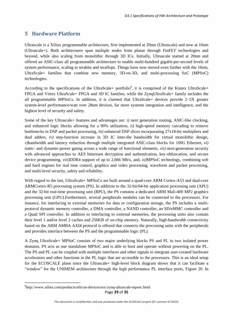
5 Hardware Platform
Ultrascale is a Xilinx programmable architecture, first implemented at 20nm (Ultrascale) and now at 16nm
(Ultrascale+). Both architectures span multiple nodes from planar through FinFET technologies and
beyond, while also scaling from monolithic through 3D ICs. Initially, Ultrascale started at 20nm and
offered an ASIC-class all programmable architecture to enable multi-hundred gigabit-per-second levels of
system performance, scaling to terabits and teraflops. Things have now moved even further with the 16nm,
UltraScale+ families that combine new memory, 3D-on-3D, and multi-processing SoC (MPSoC)
technologies.
According to the specifications of the UltraScale+ portfolio8, it is comprised of the Kintex UltraScale+
FPGA and Virtex UltraScale+ FPGA and 3D IC families, while the ZynqUltraScale+ family includes the
all programmable MPSoCs. In addition, it is claimed that UltraScale+ devices provide 2–5X greater
system-level performance/watt over 28nm devices, far more systems integration and intelligence, and the
highest level of security and safety.
Some of the key Ultrascale+ features and advantages are: i) next generation routing, ASIC-like clocking,
and enhanced logic blocks allowing for a 90% utilization, ii) high-speed memory cascading to remove
bottlenecks in DSP and packet processing, iii) enhanced DSP slices incorporating 27x18-bit multipliers and
dual adders, iv) step-function increase in 3D IC inter-die bandwidth for virtual monolithic design,
v)bandwidth and latency reduction through multiple integrated ASIC-class blocks for 100G Ethernet, vi)
static- and dynamic-power gating across a wide range of functional elements, vii) next-generation security
with advanced approaches to AES bitstream decryption and authentication, key-obfuscation, and secure
device programming, viii)DDR4 support of up to 2,666 Mb/s, and, ix)MPSoC technology, combining soft
and hard engines for real time control, graphics and video processing, waveform and packet processing,
and multi-level security, safety and reliability.
With regard to the last, UltraScale+ MPSoCs are built around a quad-core ARM Cortex-A53 and dual-core
ARMCortex-R5 processing system (PS). In addition to the 32-bit/64-bit application processing unit (APU)
and the 32-bit real-time processing unit (RPU), the PS contains a dedicated ARM Mali-400 MP2 graphics
processing unit (GPU).Furthermore, several peripherals modules can be connected to the processors. For
instance, for interfacing to external memories for data or configuration storage, the PS includes a multi-
protocol dynamic memory controller, a DMA controller, a NAND controller, an SD/eMMC controller and
a Quad SPI controller. In addition to interfacing to external memories, the processing units also contain
their level 1 and/or level 2 caches and 256KB of on-chip memory. Naturally, high-bandwidth connectivity
based on the ARM AMBA AXI4 protocol is offered that connects the processing units with the peripherals
and provides interface between the PS and the programmable logic (PL).
A Zynq UltraScale+ MPSoC consists of two major underlying blocks PS and PL in two isolated power
domains. PS acts as one standalone MPSoC and is able to boot and operate without powering on the PL.
The PS and PL can be coupled with multiple interfaces and other signals to integrate user-created hardware
accelerators and other functions in the PL logic that are accessible to the processors. This is an ideal setup
for the ECOSCALE plans since the Ultrascale+ high-level block diagram shows that it can facilitate a
“window” for the UNIMEM architecture through the high performance PL interface ports, Figure 20. In
8http://www.xilinx.com/products/silicon-devices/soc/zynq-ultrascale-mpsoc.html

D3.1 Specifications of HW Architecture and Prototype
Page 30 of 35
This document is Confidential, and was produced under the ECOSCALE project (EC contract 671632).
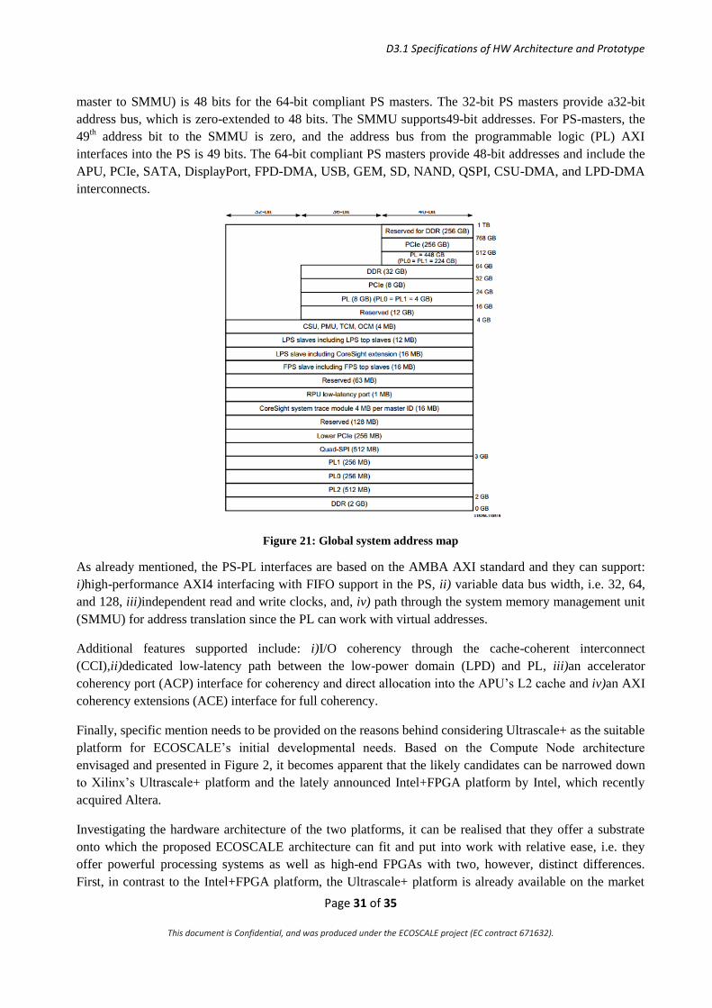
specific, as shown in the address mapping of Figure 21, the A53 processor of the Ultrascale+ FPGA has a
448-GByteregion for accessing the external world ("PL = 448GB").
Furthermore, the Ultrascale+ processors can also access memory resources in the processing system. The
PS I/O peripherals, including the static/flash memory interfaces share a multiplexed I/O (MIO) of up to 78
MIO pins. Zynq UltraScale+ MPSoCs can also use the I/Os in the PL domain for many of the PS I/O
peripherals. This is done through an extended multiplexed I/O interface (EMIO), Figure 20.
After a system reset, the PMU system automatically initializes the system and CSU ROM executes the first
stage boot loader from the selected external boot device. The process enables you to configure the MPSoC
platform as needed, including the PS and the PL. Optionally, the JTAG interface can be enabled to provide
access to the PS and the PL for test and debug purposes. Power to the PL can be optionally shut off to
reduce power consumption. To further reduce power, the clocks and the specific power islands in the PS
(for example, an APU power island) can be dynamically slowed down or gated off.
Figure 20: Zynq Ultrascale+ MPSoC top-level block diagram
The addresses used between the various processing system (PS) masters as well as between the system
memory management unit (SMMU) are virtual addresses, as shown in Figure 21. The address bus (from
D3.1 Specifications of HW Architecture and Prototype
Page 31 of 35
This document is Confidential, and was produced under the ECOSCALE project (EC contract 671632).
master to SMMU) is 48 bits for the 64-bit compliant PS masters. The 32-bit PS masters provide a32-bit
address bus, which is zero-extended to 48 bits. The SMMU supports49-bit addresses. For PS-masters, the
49th address bit to the SMMU is zero, and the address bus from the programmable logic (PL) AXI
interfaces into the PS is 49 bits. The 64-bit compliant PS masters provide 48-bit addresses and include the
APU, PCIe, SATA, DisplayPort, FPD-DMA, USB, GEM, SD, NAND, QSPI, CSU-DMA, and LPD-DMA
interconnects.
Figure 21: Global system address map
As already mentioned, the PS-PL interfaces are based on the AMBA AXI standard and they can support:
i)high-performance AXI4 interfacing with FIFO support in the PS, ii) variable data bus width, i.e. 32, 64,
and 128, iii)independent read and write clocks, and, iv) path through the system memory management unit
(SMMU) for address translation since the PL can work with virtual addresses.
Additional features supported include: i)I/O coherency through the cache-coherent interconnect
(CCI),ii)dedicated low-latency path between the low-power domain (LPD) and PL, iii)an accelerator
coherency port (ACP) interface for coherency and direct allocation into the APU’s L2 cache and iv)an AXI
coherency extensions (ACE) interface for full coherency.
Finally, specific mention needs to be provided on the reasons behind considering Ultrascale+ as the suitable
platform for ECOSCALE’s initial developmental needs. Based on the Compute Node architecture
envisaged and presented in Figure 2, it becomes apparent that the likely candidates can be narrowed down
to Xilinx’s Ultrascale+ platform and the lately announced Intel+FPGA platform by Intel, which recently
acquired Altera.
Investigating the hardware architecture of the two platforms, it can be realised that they offer a substrate
onto which the proposed ECOSCALE architecture can fit and put into work with relative ease, i.e. they
offer powerful processing systems as well as high-end FPGAs with two, however, distinct differences.
First, in contrast to the Intel+FPGA platform, the Ultrascale+ platform is already available on the market

D3.1 Specifications of HW Architecture and Prototype
Page 32 of 35
This document is Confidential, and was produced under the ECOSCALE project (EC contract 671632).
while, second, the former shall have a considerably greater power consumption footprint that shifts it into a
region that is unacceptably large for ECOSCALE’s target power consumption demands. As a result, the
ECOSCALE consortium has concluded onto the employment of Ultrascale+ as a development platform
that balances high-end, high-performance behaviour with acceptable power consumption.
5.1 ECOSCALE Prototypes The final ECOSCALE prototype will consist of multiple (about 16) interconnected prototype cards, which
will form together an ECOSCALE PGAS. The prototype card, which will address all the ECOSCALE’s
requirements, will be developed by the ExaNeSt project. It will support 4 Ultrascale+ FPGAs, 18 GBytes
of memory per FPGA, an SSD and multiple high-speed links for internal and external communication. The
ExaNeSt prototype card will become available in Q3 2016.
Meanwhile, we plan to use other available commercial Ultrascale+ boards. While such development boards
support a single FPGA and they don’t provide high-density solutions, they are good candidates for the
initial development of the ECOSCALE architecture until the ExaNest main prototype card is available.
The following Ultrascale+ boards will soon become available in the market and they are potential
development platforms for ECOSCALE:
The Trenz board: Trenz Elecronic TE08089 is an MPSoC module integrates a Xilinx Zynq
UltraScale+, max. 8 GByte DDR4 SDRAM with 64-Bit width, max. 512 MByte Flash memory
for configuration and operation, 20 Gigabit transceivers, and powerful switch-mode power
supplies for all on-board voltages. The Trenz board is plugged into a Trenz board which provides
external connectivity and power supply. The total cost of both boards is close to 3500€ and they
will be available around about end of May. ECOSCALE will use this platform as soon as it
becomes available.
The iVeia board: iVeia Atlas-III-Z8 SoM10
supports a Xilinx ZynqUltraScale+ and it is available
in limited quantities. However, the carrier card is not available yet. The cost of the boards is
around 5200 euros.
The Xilinx development board: The Xilinx ZCU102 development supports a Xilinx
ZynqUltraScale+ FPGA and it is estimated to be available in a few months.
5.2 Final Hardware Prototype The prototype card from the ExaNeSt project is estimated to cost around 11.5 k€ (2 k€ x 4 FPGAs + 1 k€ x
SSD + 0.5 k€ x other components + 2 k€ x PCB). TSI has allocated around 192 k€ for the prototype cards
and thus the final prototype can support around 16 of those cards. This prototype will support 64 Xilinx
Ultrascale+ FPGAs featuring:
64 64-bit quad-core Cortex A53
64 x 600 = 38.4 K logic cells
64 x 18 = 1.152 TBytes of DDR4 memory
16 x 960 = 15.4 TBytes of SSD storage
9 http://www.trenz-electronic.de/products/fpga-boards/trenz-electronic/te0808-zynq-ultrascale.html
10 http://www.iveia.com/atlas-iii-z8x

D3.1 Specifications of HW Architecture and Prototype
Page 33 of 35
This document is Confidential, and was produced under the ECOSCALE project (EC contract 671632).
Each Ultrascale+ chip, including both CPUs and FPGA resources, corresponds to an ECOSCALE worker,
while the 16 interconnected ExaNeSt prototype cards (including 16 x 4FPGAs=64 Workers in total)
correspond to an ECOSCALE Compute Node. In this way the prototype will support a full Compute Node.
The interconnection topology of the 16 prototype cards will be based on the results of the ExaNeSt project.
We estimate that ExaNeSt will propose a 2D-torus topology, as shown in Figure 22, or a 3D-torus topology
for direct communication between the prototype cards that form the Compute Node. Some links coming of
the prototype cards will be connected to an external router that will be responsible for interconnecting the
Compute Nodes together (for potential future extensions of the ECOSCALE prototype) or the daughter
cards of a Compute Node depending on the interconnection topology specified by the ExaNeSt project.
Figure 22: ExaNeSt prototype cards interconnected in 2D-torus topology to form a Compute Node.

D3.1 Specifications of HW Architecture and Prototype
Page 34 of 35
This document is Confidential, and was produced under the ECOSCALE project (EC contract 671632).
6 Conclusions This deliverable has been responsible for laying out the specifications for the ECOSCALE hardware
architecture as well as the ECOSCALE prototype. First, a short background review is offered that presents
a high-level view of the ECOSCALE architecture. This helps in constructing an outline for the sub-
elements' specifications presented later.
First, the UNIMEM architecture is addressed and specifically how it will be developed within the context
of ECOSCALE. Its main purpose is to facilitate memory coherence islands, i.e. cache coherent, and in the
case of ECOSCALE such a coherence island is a unique Worker Node (a collection of Workers is what
makes up a Compute Node).
Each Worker shall support a physical address mapping for accessing its local memory, its local peripherals
and a "window" to the external world. The details for those actions are defined and it is decided that static
mapping will be used for direct memory access that supports the entire global address space. Furthermore,
one key ECOSCALE feature is the ability for remote cache-coherent accesses, hence, two different
UNIMEM memory models are described, both of which will be supported by the ECOSCALE system.
Subsequently, the UNILOGIC architecture is described that builds upon the pre-existing UNIMEM
architecture in order to facilitate efficient distributed reconfigurable acceleration through parallel access of
reconfigurable blocks by different Workers.
Next, the details and workings of the Hardware Virtualization Block are defined in order to form a set of
specifications for its operation. This virtualization block is responsible for executing OpenCL workgroups
belonging to either the same or different (or both) kernel calls onto the available hardware workgroup set in
the PL fabric. This is a laborious and complicated task that requires the clarification of several issues such
as how to split an OpenCL kernel ND range into different workgroups and perform workgroup scheduling
in relation to those available in the reconfigurable accelerators and all this under different OpenCL kernel
call scenarios.
Another significant element of the ECOSCALE architecture, which merits detailed investigation in order to
extract a set of specifications to which it will have to adhere to, is the memory accesses routed by the local
interconnects of the Workers and the global interconnect of the UNIMEM architecture. For this, three
different address spaces are identified, i.e. the Virtual Address space, the Physical Address space and the
Global Address Space.
Naturally, the ECOSCALE system heavily relies upon interconnection protocols that must ensure that it
operates within specifications. The interconnection protocols that will be used for efficient Worker Node
communication are the AXI-based multi-level interconnect for PL and ARM (PS) communication.
Furthermore, a Network-on-Chip model called STNoC will be utilised as a greater on-chip communication
infrastructure for the final ECOCALE prototype consisting of AXI network interfaces, routers and links in
order to provide a topology that supports the ECOSCALE Compute Node at a performance level that is
greater than that achieved by the initial ECOSCALE platform, i.e. Ultrascale+.
This brings us to the closing stages of the deliverable since here is where the specifications of the actual
implementation platforms are defined. First, it is agreed that a Xilinx demonstration platform will be used,
i.e. Ultrascale+, since it consists of a high-end Zynq FPGA as well as powerful PS-PL communication
through high-performance AXI ports. The later stages of ECOSCALE, however, will lead to a final

D3.1 Specifications of HW Architecture and Prototype
Page 35 of 35
This document is Confidential, and was produced under the ECOSCALE project (EC contract 671632).
hardware prototype that will be much more powerful. This is going to be based upon the prototype card of
a different project, i.e. ExaNest, enriched by additional Ultrascale+ FPGAs.


![Entwicklung eines Lehrpraktikums auf Basis der Zynq … · and understand the ARM AMBA AXI Protocol v2.0 Specification, along with the AMBA4 AXI4-Stream Protocol v1.0.“ [1] (Praktikumsaufgabe](https://img.dokumen.tips/doc/110x75/5b1589237f8b9a8b288cb24b/entwicklung-eines-lehrpraktikums-auf-basis-der-zynq-and-understand-the-arm-amba.jpg)