Embed Size (px)
Citation preview
Project no. 32447
RAMseS
Renewable Energy Agricultural Multipurpose System for Farmers
Specific Targeted Research or Innovation
Renewable energies for Mediterranean specific needs
WP2: Power system design and Prototyping Task 2.2: Power system assembly and first test
Deliverable D2.2 PV Power Generation System Layout for Testing Activity
Actual submission date: 30/09/2008 Start date of project: 01/10/2006 Duration: 42 Months ADMElectric (partner 7)
Project co-funded by the European Commission within the Sixth Framework Programme (2002-2006)
Dissemination Level
PU Public
PP Restricted to other program participants (including the Commission Services)
RE Restricted to a group specified by the consortium (including the Commission Services)
CO Confidential, only for members of the consortium (including the Commission Services)
X

ADM Electric RAMseS Deliverable D2.3
2
TABLE OF CONTENTS
INTRODUCTION 3
2- LIST OF COMPONENTS: 4
3- SCHEMATICS 6
3.1 PV System General Layout 6
3.2 PV system detailed layout 7
3.3 Data Logging / WebBox Diagram: 8
3.4 Mechanical Structure: 9
3.5 Panels Layout: 9
3.6 Panels wiring layout: 10
4- SYSTEM CONFIGURATION: 12
4.1 Solar Inverter Sunny Boy 2500: 12
4.2 Power Inverter Sunny Island 5048: 15
5- WIRING DIAGRAMS 21
5.1 Grounding: 21
5.2 DC connection: 21
5.3 AC connection: 22
5.4 Battery Temperature Sensor: 23
5.5 Communication for Multi-Device connection: 23
5.6 Multifunction Relays 1 and 2: 24
5.7 Interface for external communication: 25
6. DATA COLLECTION AND MONITORING 26
6.1 Sunny Web Box in brief 26
6.2 Screen shots from RAMseS solar plants: 29
ADM Electric RAMseS Deliverable D2.3
3
Introduction
The present deliverables described the installed PV power generation and storage system at RAMseS MPC Site : Mar Sarkis Monatsrey – Achkout Lebanon Under this deliverables we detailed the design which we reported under deliverable D2.1: Power Generation System Design where we described all the detailed design, components used, functionality and wiring diagrams. Appended to this deliverable all users’ manuals for the major components used Detailed construction drawings will be reported under deliverable 4.3.

ADM Electric RAMseS Deliverable D2.3
4
2- List of components:
The following table lists all major equipments installed for the solar powr generation and storage system in Mar Sarkis Monsatery , ACHKOUT-Lebanon.
Item Description Part NB. QTY Manufacturer
1
Grid-connected inverter Max DC input: 2700wdc MPPT: 224 – 600 VDC Max AC output: 2500wac Efficiency: 94.1%
SB2500 4 S.M.A Technologie AG
2
Stand alone inverter Max input power: 12.8KW Output nominal AC voltage 230V Continuous AC output for 30/1/5min: 6500/ 7200/ 8400 watts Output nominal AC current: 21.7A
SI5048 2 S.M.A Technologie AG
3
Communication center RS45 Interface up to 50 inverters, max 1200m Ethernet / fast Ethernet connection Memory expansion 1GB
Sunny WebBox 1 S.M.A Technologie AG
4
Irradiation sensor RS485 to the data logger WebBox Solar irradiation ± 8% Temperature: Connected to the Irradiation sensor Platinum sensor PT100 for determination of PV temperature Precision ± 0.5 degree C
SESOBOX 1 S.M.A Technologie AG
5
Ambient temperature sensor Connected to the Irradiation sensor Platinum sensor PT100 for determination of ambient temp. Precision ± 0.5 degree C
TmpAmb 1 S.M.A Technologie AG
6 Anemometer Connected to the Irradiation sensor External wind sensor
Wind 1 S.M.A Technologie AG
7 Fuse Holder on the DC side of the 2 SI 5048 and the storage batteries 250A
SI-BatFuse.03-250
1 S.M.A Technologie AG
8
PV panels Maximum power point:138Wp Maximum power voltage: 18.2V Maximum power current: 7.59A Open circuit voltage: 22.6V
SLK 36M6L 72 SILIKEN

ADM Electric RAMseS Deliverable D2.3
5
Item Description Part NB. QTY Manufacturer
9
Control panel Containing all the contactors, control devices, the circuit breakers, fuses, junctions, busbars, Indicators…
Cabinet 1 ADM electric
10 Grouding system Formed of grounding rods, earth bar, bare copper cable and grouding clamps
1 ADM Electric
11
PV Panels support structure Aluminum sloped structure holding 6 PV panles Assembled by bolts Installed on the roof by means of roll-bolts
12 ADM Electric
12
Lead Acid Batteries Nominal capacity of each cell: 2350Ah / 2V weight: 108KG Dim: 215 x 277 x 845 mm Internal resistance: 0.24 mohm C10: 1751Ah
OPzS Solar 2350Ah/
NVSL022350WC0FA
24 Exide Technologies-
TUDOR

ADM Electric RAMseS Deliverable D2.3
6
3- Schematics
3.1 PV System General Layout

ADM Electric RAMseS Deliverable D2.3
7
3.2 PV system detailed layout

ADM Electric RAMseS Deliverable D2.3
8
3.3 Data Logging / WebBox Diagram:
The Sunny WebBox is connected to the four ‘grid-tied’ inverters SB2500 through the RS485 cable. The cable continue through the ‘off-grid’ inverter the SI5048, master inverter only and finish at the RS485 power injector which is used to collected data from the Sunny Sensor Box and to supply it with power at the same time. At the two terminations edges (sunny sensor box and the WebBox) a termination resistor of 120 ohm is installed. The SI5048 master inverter collects all the data from the SI5048 slave inverter and send it to the data logger (WebBox). The connection is made through the synchronization com port using a twisted pair RJ45 UTP cable which is used for internal communication between several SI5048 inverters (one master and several slaves). For that we don’t need to connect the slave SI5048 to this network.

ADM Electric RAMseS Deliverable D2.3
9
3.4 Mechanical Structure:
3.5 Panels Layout:
Mnufacturer: SILIKEN Model: SLK 36M6L Part number: 013292 Weight: 12Kg Maximum power point: 138Wp Maximum power voltage: 18.2V Maximum power current: 7.59A Open circuit voltage: 22.6V Short circuit current: 8.04A

ADM Electric RAMseS Deliverable D2.3
10
3.6 Panels wiring layout:
We divided the system into 4 streams; each stream is connected to one solare inverter Sunny Boy SB2500 Each stream join 3 PV supports with 6 panels, totaling 18 PV panels wired in series and providing 2484 Wc

ADM Electric RAMseS Deliverable D2.3
11
PV Panels : Siliken SLK36M6L characteristics @ 25 deg C: Maximum power point: Pmpp = 138Wp. Maximum power voltage: Umpp = 18.2V. Maximum power current: Impp = 7.59A Open circuit voltage: Voc = 22.6V These values for 1000W/m2 radiation, 1.5AM and 25 degree Celsius cell temperature. Each stream
� 18 panels * 22.6Voc = 406.8VDC. (accepted) � 18 panels* 18.2Vmpp = 327.6VDC. (accepted)
NB: In the data sheet of the SB 2500, the PV voltage range Vmpp should be between 250 and 600VDC. Siliken SLK36M6L characteristic @ 50 degrees Celsius: Maximum power point: Pmpp = 131Wp. (-5%) Maximum power voltage: Umpp = 16.3V. (-10%) Maximum power current: Impp = 8.2A (+8%) Open circuit voltage: Voc = 20.3V (-10%) These values for 1000W/m2 radiation, 1.5AM and 50 degree Celsius cell temperature.
� 18 panels * 20.3Voc = 365.4VDC. (accepted) � 18 panels* 16.3Vmpp = 293.4VDC. (accepted)
ADM Electric RAMseS Deliverable D2.3
12
4- System Configuration:
4.1 Solar Inverter Sunny Boy 2500:
In our system, and as we already seen, we have 4 solar inverters type SB2500 ‘grid-tied’. The total power generated from these inverters is 10KW. The PV panels are connected to the DC side of these inverters to form an AC signal on the output. We can connect maximum 3 streams or strings to each inverter; it depends from the calculation of the power and the voltage and how to equilibrate the system. Usually the ‘grid-tied’ inverters are configured by SMA, in case we need to change any parameter in the configuration, for example if we want to put the ‘default’ parameter to ‘Off-grid’ we need a password from SMA so we can access the list parameters and modify it. This is done to secure that nobody can change the parameter list, only the authorized persons. Putting the ‘default’ parameter to ‘off-grid’ means that we are configuring the system to work in ‘Stand alone’, in this case all the SB2500 detect the presence of the ‘off-grid’ inverter SI5048 and wait for it to control the whole system.
Technical data:
• Maximum DC power Input: 2700 WDC
• Maximum DC voltage Input: 600VDCmax
• PV voltage range, MPPT (UMPP): 224 - 600VDC
• Maximum Input current (Ipv): 12ADC per string
• Maximum number of strings (parallel): 3
• Maximum AC power Output: 2500WAC
• Nominal AC power Output: 2300WAC
• THD of grid current: <4%
• Nominal AC voltage Output: 220 – 240VAC
• Nominal AC frequency Output: 50HZ – 60HZ
• Power factor (cosφ): 1
• Maximum output current P= UxIxcosφ => I=P/U=2500/220= 11.4A
• Efficiency: 94.1%
• Weight: 30Kg Connecting the DC side: To connect the PV generator to the inverter, proceed as follows: 1. Plug the DC plugs into devices sockets. 2. Attach the handle of the electronic solar switch ESS. 3. Switch the supply line circuit breaker to the ON position. Disconnecting the Inverter: 1. Disconnect the AC side. 2. Remove the ESS. 3. Remove the PV plug connectors from the inverter immediately.

ADM Electric RAMseS Deliverable D2.3
13
Appropriate usage: The Sunny Boy allows photovoltaic solar energy to be converted and fed into a 220 – 240V 50Hz low voltage grid.
Working mode: There are 3 modes of work in the ‘Grid-tied’ inverters: i. MPP mode (standard setting): ii. Constant voltage mode. iii. Turbine mode. In our case we are using the inverters only in MPP mode (maximum power point) based on the power received from the PV string connected to the inverter. The inverter automatically determines the MPP voltage of the solar generator, which is defined in the internal control system as the desired PV voltage. In MPP mode, the point of maximum feed-in performance PAC is set by adjustment of the desired PV voltage on the solar generator. Commissioning: 1. First of all switch the line circuit breaker to the “ON” position. 2. Now look at the LED display and consult the LED table to check whether the Sunny Boy is in a fault-free and appropriate operating mode.
Note: If the bottom yellow LED flashes four times at intervals of one second, the grid voltage and the PV generator must be immediately disconnected from the Sunny Boy! There is a risk of damage to the inverter resulting from excessive DC input voltage!

ADM Electric RAMseS Deliverable D2.3
14
Led signal: (Installation guide SB 25-30-11-SE0307)
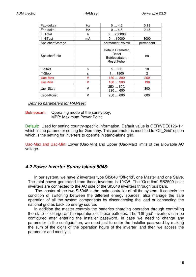
Parameter Settings: These parameters settings are fixed from the factory. To change any parameter an authorization must be provided by SMA. Unauthorized changes to the operating parameters may result in: � Voiding the Sunny Boy’s warranty. � Voiding the Sunny Boy’s operating approval certificate. � Injury as a result of changing the internal safety routines. Most of the parameters are kept the same, related to the inverter hardware. The ones in the red color are the ones related to the Lebanese electrical norms or to our RAMses project. The parameters in green are the ones modified.
Name Description Value range Factory setting
ACVtgRPro V 230 … 300 253
Antilsland-Ampl grd 0 …10 0
Antilsland-Freq mhz 0 … 2000 500
Betriebsart
MPP,Konstantspg., Stop, Turbine
MPP
Default* GER/VDE0126-1-1, GB/G83, Off_Grid,
SP/RD1663, Other,trimmed
GER/VDE0126-1-1
dFac-MAX Hz/s 0.005 … 4.0 4
dZac mOhm 0 … 20000 700
E_Total Kwh 0 … 20000
ADM Electric RAMseS Deliverable D2.3
15
Fac-delta+ Hz 0 … 4.5 0.19
Fac-delta- Hz 0 … 4.5 2.45
h_Total h 0 … 200000
I_NiTest mA 0 … 15000 8000
Speicher/Storage permanent, volatil permanent
Speicherfunkt
Default Prameter, Reset
Betriebsdaten, Reset Feher
no
T-Start s 5 .. 300 10
T-Stop s 1 … 1800 2
Uac-Max V 180 … 300 260
Uac-Min V 180 … 300 198
Upv-Start V 250 … 600/ 290 … 600
300
Usoll-Konst V 250 … 600 600
Defined parameters for RAMses:
Betriebsart: Operating mode of the sunny boy. MPP: Maximum Power Point Default: Used for setting country-specific information. Default value is GER/VDE0126-1-1 which is the parameter setting for Germany. This parameter is modified to ‘Off_Grid’ option which is the setting for inverters to operate in stand-alone grid. Uac-Max and Uac-Min: Lower (Uac-Min) and Upper (Uac-Max) limits of the allowable AC voltage.
4.2 Power Inverter Sunny Island 5048:
In our system, we have 2 inverters type SI5048 ‘Off-grid’, one Master and one Salve. The total power generated from these inverters is 10KW. The ‘Grid-tied’ SB2500 solar inverters are connected to the AC side of the SI5048 inverters through bus bars.
The master of the two SI5048 is the main controller of all the system. It controls the condition of switching between the different energy sources, also manage the safe operation of all the system components by disconnecting the load or connecting the national grid as back up energy source.
In addition the master controls the batteries charging operation through controlling the state of charge and temperature of these batteries. The ‘Off-grid’ inverters can be configured after entering the installer password. In case we need to change any parameter in the configuration, we need just to enter the installer password by making the sum of the digits of the operation hours of the inverter, and then we access the parameter and modify it.

ADM Electric RAMseS Deliverable D2.3
16
Technical description of SI 5048:
� Input voltage range: 230V (172.5 – 250V) � Input frequency: 40 – 70Hz. � Maximum AC input current (adjustable): 56A (2 – 56A) � Maximum input power: 12.8KW � Output nominal AC voltage (adjustable): 230V (202 – 253V) � Output frequency: 45 – 65Hz � Continuous AC output at 25’C / 45’C: 5KW / 4KW � Continuous AC output at 25’C for 30/5/1min: 6500 / 7200 / 8400 � Output nominal AC current: 21.7A � Maximum current: 100A (for 100ms) � Output THD factor: <3% � Power factor: -1 to +1 � Battery voltage range: 48V (41 – 63V) � Maximum battery charging current: 120A � Continuous charging current: 100A � Battery capacity: 100 – 10 000 Ah
Operation mode:
The SI is connected to a battery bank, and forms the AC grid in our stand-alone system. The Sunny-island controls the voltage and frequency on the AC side. Both the loads as well as the generators (e.g. Sunny Boy solar inverter) are directly connected to this AC grid. In the event of an energy surplus (e.g. high solar irradiation and low consumption), the SI draws energy from the AC grid and uses it to charge the batteries. If there is an energy shortage, (little or no solar irradiation and high consumption), the SI supplies the grid with the aid of the batteries. When PV is not available or no solar irradiation exists and consumption is high (night) then:
The load is supplied from the batteries alone (DOD must be >40%), when the
DOD is equal to 40%, the SI5048 connect the national grid to AC2 through the relay 1 of the master. (Used as generator)
The national grid recharges the batteries. When the DOD achieve 80% the SI5048
disconnect automatically the grid and switch to the batteries again Based on the Sunny Boy MPP working mode, here are the 4 scenarios for our system. a) First scenario: “working mode during the day” The Sunny Boy (4xSB) provides the loads with energy when solar energy is available.
• If the power generated by the PV system is equal to the load then the PV system supplies the load alone.
• If the power generated by the PV system is higher than the load then the PV system supplies the load and refills he battery with the exceeding.

ADM Electric RAMseS Deliverable D2.3
17
• If the power generated by the PV system is not enough to supply the load then the PV will draw the balance form the batteries.
The SI5048 starts in stand alone grid operation. Once the device is operating, it checks for the presence and availability (voltage and frequency) of the external grid. When the sunny boy is operating, it’s always synchronized to SI5048. SB provides as much as possible to the load. If there not enough power from the PV to supply the load then: � High priority: the batteries provide the rest of the needed power. Batteries charging level must be >40% DOD. � Low priority: when the DOD of the batteries is equal to 40% the national grid is connected to the system through the relay 1 of the master to supply to recharge the batteries and the load is shed. When the DOD of the batteries achieves 80% of the charging level, automatically the SI5048 disconnect the national grid and switch on the load again. Note: if the national grid is not available to recharge the batteries, and if the DOD achieves a level of 38%. The SI5048 disconnect all the loads through the relay 2 of the master to protect the batteries from deep discharge. Note: the national grid is connected through the relay 1 of the master SI5048. b) Second scenario: “working mode during the night” When PV is not available or no solar irradiation exists and consumption is high (night) then:
• The load is supplied from the batteries alone (DOD must be >40%) When the DOD is equal to 40%, the SI5048 connect the national grid to AC2 through the relay 1 of the master. (Used as generator)
• The national grid recharges the batteries. When the DOD achieve 80% the SI5048 disconnect automatically the grid and switch to the batteries again. c) Third scenario: “ No power” When PV and the national grid are not available and if the DOD of the batteries achieve <40% then:
• The load is disconnected
• System shut down until new energy source is available. d) Fourth scenario: “No Load” If solar power (PV) is available and batteries are fully charged and we don’t have any load then:
The SI5048 limit the output of the SUNNY BOY inverter. To prevent the excess energy from overcharging the batteries, the SI5048 recognize this situation and changes the frequency of the AC output. This frequency adjustment is analyzed by the sunny boy. As soon as the grid frequency increases beyond the value, the sunny boy limits its output power accordingly.

ADM Electric RAMseS Deliverable D2.3
18
How to switch off the SI5048:
Before performing any maintenance or installation work, proceed in the order below to switch off the SI5048: i. Switch off all consumer appliances. ii. Press and hold the “ENTER” key until the “HOLD KEY TO STOP” message appears. iii. Press and hold the “ENTER” key until the SI5048 stops and the “STANDBY – To start
press <ENTER>” message appears. iv. Switch off the Sunny Island 5048 using the DC circuit breaker and also disconnect the
device from the batteries (e.g. using the optional SI-BATTCASE Load disconnecting switch).
v. Then disconnect the SI5048 from the grid/generator and island grid (AC1 & AC2). vi. Make sure that the SI5048 has been disconnected from all voltage sources. vii. Wait at least 5 minutes to let the capacitors discharge and allow the voltage inside the
device to drop to a safe level. The capacitors need approximately 30 minutes for completely discharging. A short circuit on the DC side has to be avoided by all means.
viii. Open the housing cover to ensure that the device is not under voltage.
Setup of the SI5048 (Step by step):
The Quick configuration guide (QCG) allows you to quickly install and commission the SI5048. Simply answer 6 questions, and you are finished.
1. System configuration? 2. Device type? 3. Battery type? 4. Battery capacity? 5. Maximum generator current? 6. Generator interface?
Once you leave the menu, the remaining parameters are set to default values! And if further fine tuning is required: no problem. The SI5048 allows the individual parameters to be accessed specifically.
When starting the QCG, useful parameter values are set by default! The QCG is automatically activated when the device is started for the first time.
1) Switch on the SI5048 by switching the DC circuit breaker to “ON” position. 2) Wait “SIBFSBoot V1.00” to finish. 3) To init system hold <ENTER>. 4) Press and hold <ENTER> until the SI5048 peeps 3 times. 5) You are now in the QCG you can select:
• “Start System”: in case you are in the QCG by mistake & only want to restart.
• “New System”: in case you want to commission a new system or make changes of the plant configuration.
• “New Battery”: in case you want to change the main battery settings, but to keep the system configuration.
• “Energy charge”: in case you want to charge a deeply discharge battery.

ADM Electric RAMseS Deliverable D2.3
19
6) The following parameters must be set for “New System”.
• Device type: Master, Slave1, Slave2, Slave3.
• System configuration: presetting is “1phase 1SI”
• Voltage/frequency type: 230V-50Hz, 220V-60HZ, presetting is 230V-50Hz.
• Date
• Time
• Battery type (VRLA, FLA, NiCd), presetting is “VRLA”.
• Nominal battery voltage : 44 to 48V in 2-V steps for FLA and VRLA, 43.2V to 48V in 1.2-V steps for NiCd, presetting is “48.0V”
• Nominal battery capacity (100 to 10 000Ah), presetting is “100Ah”
• External power supply unit (PV only, Gen, Grid, Gen m Grid)
• Maximum generator current (0 to 224A), presetting is 16A.
• Generator interface (Manual, GenMan, Autostart), presetting is “Manual”.
• Maximum grid current (0 to 224A), presetting is 16A.
The following parameters must be set for “New battery”
• Battery type (VRLA, FLA, NiCd), presetting “VRLA”.
• Nominal battery capacity (100 to 10 000Ah), presetting is 100Ah.
• Nominal battery voltage (44 to 48V), presetting is 48.0V
In case of a system with more than one SI5048, it is required to run the QCG on the Slaves before starting the Master device. Do not start the master device beforehand! The SI5048 uses the ‘Single Point operation’ concept. In case of a system with more than one device all entries are made on the Master. The complete system is configured; events, warnings & failures are confirmed. Exception: When starting the device for the first time, you must set the slave devices as slave in the QCG & everything else is performed at the Master. Single Point of operation also means that all data, including the slave data, must be saved on the MMC/SC card of the Master device. The list of parameters:
• Device type: Master
• System configuration: ‘1 phase 2SI’
• Voltage frequency type: 230 – 50 hz
• Date:
• Time:
• Battery type: FLA
• Nominal Battery voltage: 48VDC
• Nominal Battery capacity: 1751AH
• External power supply unit: GEN
• Maximum diesel generator current ( 0 to 224A) : 6A
• Generator interface: Autostart
• Maximum grid current (0 to 224A) : 0A
Go to the direct access under the menu ‘600 #Direct Access’

ADM Electric RAMseS Deliverable D2.3
20
242.01 = Lod1SocTm1Str = 40% SOC limit for load shedding 1 start for T1 242.02 = Lod1SocTm1Stp = 60% SOC limit for load shedding 1 stop for T1 242.03 = Lod1SocTm2Str = 0% SOC limit for load shedding 1 start for T2 242.04 = Lod1SocTm2Stp = 0% SOC limit for load shedding 1 stop for T2 242.05 = Lod1Tm1Str = 0 Load shedding 1 time 1 242.06 = lod1Tm2Str = 0 Load shedding 1 time 2 231.09 = ExtSrc = GEN 233.07 = GnStrMod = Autostart 234.03 = GnSocTm1Str = 45% SOC limit for switching on generator for time 1 234.04 = GnSocTm1Stp = 80%
SOC limit for switching off generator for time 1 234.05 = GnSocTm2Str = 0% SOC limit for switching on generator for time 2 234.06 = GnSocTm2Stp = 0% Soc limit for switching off generator for time 2 234.07= GnTm1Str = 0 Time1 for generator request 233.08 = GnOpTmMin = 15 Minimum generator operating 15 minutes 233.09 = GnStpTmMin = 15
Minimum generator stop time 15 minutes 241.01 = Rly1Op = AutoGn Automatic generator connection 241.02 = Rly2Op = AutoLod1Soc Automatic connection / disconnection of loads due to SOC1 550.01 = CardFunc = StoEvtHis Writes event list 550.03 = DatLogEna = ON Activates automatic data storage

ADM Electric RAMseS Deliverable D2.3
21
5- Wiring Diagrams
5.1 Grounding:
Since a connection between N and PE is required for proper operation, we decided to make an earthing system outside the devices, and connect all the electrical equipments lids to the earthing bus bar inside the electrical cabinet. We grounded the devices through the earthing busbar with a copper conductor with 10mm² cross section The grounding system layout:
5.2 DC connection:
Four cables 70mm² connected from the two SI5048 output (One “DC-“& one “DC+” are available in each SI5048) to the fuse holder of the storage batteries. We placed the two SI5048 inverter near the batteries so the cable going from the fuse holder to the batteries extremities be short as possible, because long cables or the insufficient cable diameter reduce the system efficiency and the overload capability.

ADM Electric RAMseS Deliverable D2.3
22
5.3 AC connection:
The maximum permissible current that may flow through the AC input of the SI5048 is 56A.
AC1: The Sunny Boy is connected to the AC1 output of the SI5048. As our system is a parallel 1 phase system, we connected all the parallel single phases of the 2 SI5048 together on the same bus bar. For example, the AC1 phase of the first and the second inverter are connected to the phase bus bar, and the AC1 neutral of these two inverters are connected to the neutral bus bar, same for the PE.

ADM Electric RAMseS Deliverable D2.3
23
AC2: The Sub-distribution of the generator /public grid is connected to the output AC2 of the SI5048.
In our case we have 1-phase system, the national grid is connected to the AC2 side of the Master and the slave inverter of the SI5048. The cables cross sections and length are identical (16mm²)
5.4 Battery Temperature Sensor:
The battery temperature sensor measures the temperature of the connected battery. This is necessary since the optimum charging voltage for a battery largely depends on the temperature. A battery temperature sensor must be connected for operating the SI5048. In case of a failure of the temperature sensor, the SI5048 operates in a safe setting which results in insufficient charge sequences of the battery. A warning is displayed; the damaged temperature sensor should be replaced immediately. Only one battery sensor connected to the respective master is required for a cluster.
5.5 Communication for Multi-Device connection:
To increase the overall power of the system we need to add the power of the 2 SI5048 together to get maximum power of 10KW. The 2 SI5048 are connected together in parallel (1 phase). This connection is made for internal communication between the 2 inverters, and it is made by using an RJ45 UTP cable (twisted pair). The 2 devices communicate with each other via this RJ45 communication cable.

ADM Electric RAMseS Deliverable D2.3
24
5.6 Multifunction Relays 1 and 2:
The relays have both open and close functionality. You can only assign one function to the relay. In case of a cluster, the relays of the slaves are configured by the master. For logical reasons and to protect our system, the functions generator request & load shedding are connected respectively to the relay 1 and 2 of the MASTER inverter, since, in case of a failure, the slave waits for acknowledgement while the master continues to operate and at least limited operation is possible. Load Shedding: The SI5048 automatically switch off loads to protect the batteries from deep discharge. To do this, an external contactor is installed between the Sunny Island 5048 and the loads. “Disconnect only the loads, never disconnect the generators”. The loads will be disconnected when the batteries achieve a 40% of there DOD (depth of discharge) and reconnected when the DOD achieve a 60%. Generator Start: We are using the national grid which is connected to the relay1 as generator so we can use the functions of the generator (Run/Stop) to control the connection or the disconnection of the grid. If we define the energy source connected to the relay 1 as grid, the SI5048 will take it as highest priority and it will be connected to it all the time. Usually the public grid is connected directly to the AC2 connectors and not through any relay and that’s why the SI5048 switch to it always without any condition, simply because it will be always present as an energy source.

ADM Electric RAMseS Deliverable D2.3
25
5.7 Interface for external communication:
The communication interface is used to communicate with the SMA communication devices (Sunny WebBox). Depending on the selected communication interface, up to 50 inverters can be detected. The following communication interfaces can be integrated into the SI5048: � RS232 � RS485
Communication device Sub-D 9 pins
RJ45 Socket
RS232 RS485
2 1 RXD A (Data - )
3 3 TXD B (Data +)
5 2 GND GND
Data transmission rate: data transmission rates (1200 to 19200 bps). 1200bps (factory settings) the SI5048 uses the SMA-NET protocol for communication.
ADM Electric RAMseS Deliverable D2.3
26
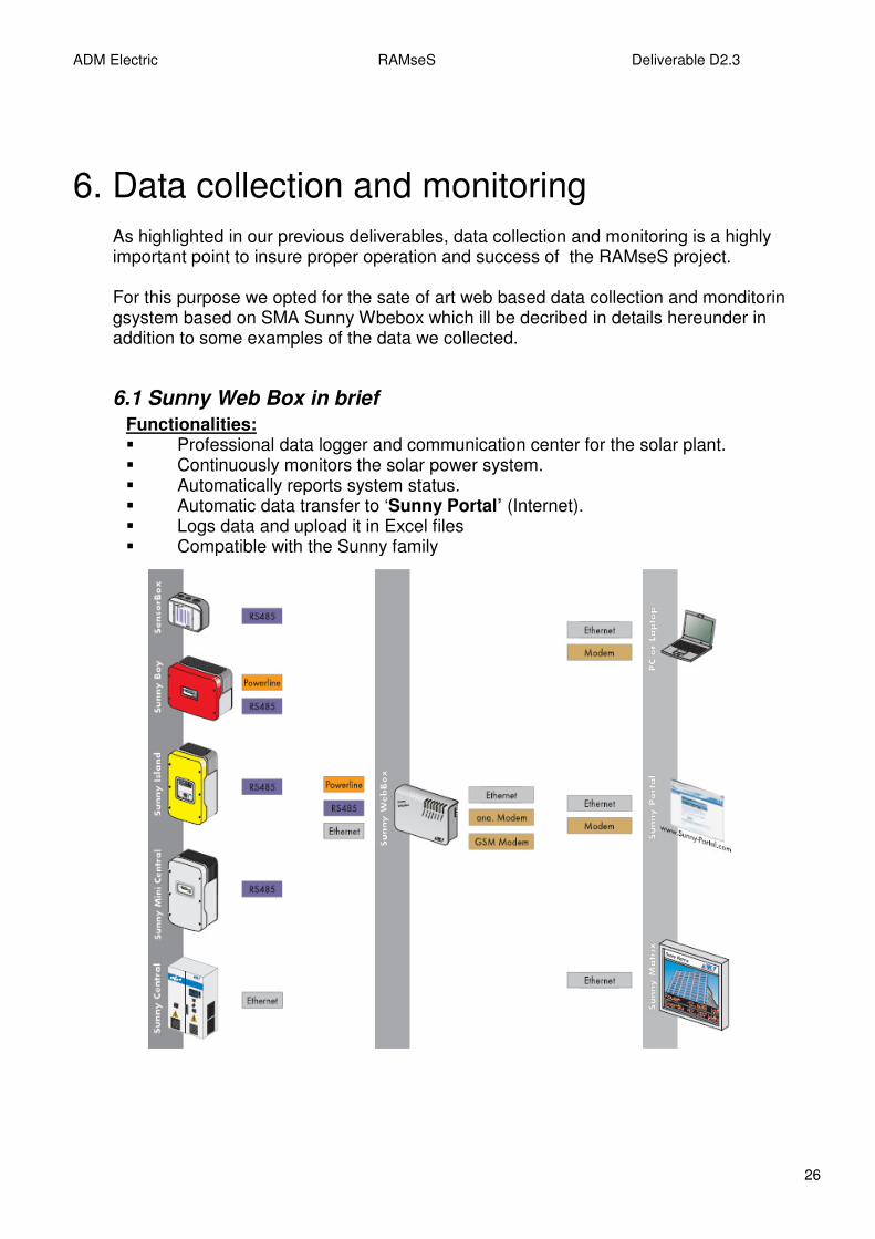
6. Data collection and monitoring
As highlighted in our previous deliverables, data collection and monitoring is a highly important point to insure proper operation and success of the RAMseS project. For this purpose we opted for the sate of art web based data collection and monditorin gsystem based on SMA Sunny Wbebox which ill be decribed in details hereunder in addition to some examples of the data we collected.
6.1 Sunny Web Box in brief
Functionalities: � Professional data logger and communication center for the solar plant. � Continuously monitors the solar power system. � Automatically reports system status. � Automatic data transfer to ‘Sunny Portal’ (Internet). � Logs data and upload it in Excel files � Compatible with the Sunny family

ADM Electric RAMseS Deliverable D2.3
27
Application:
We are using the Sunny WebBox as data logger for our system. The Sunny WebBox provides the connection between the solar system and us via an integrated web interface. As future step, the WebBox will be connected to the internet through the Sunny Portal. Connecting the Sunny Portal to the internet provides new options for analyzing and displaying the data on a PC using the Internet browser. The data can be generated and displayed as charts or load curves.
As we already seen before, the WebBox is connected to the various inverters and to the sunny sensor box using the RS485 communication. We access the WebBox via Ethernet network by using a crossover cable. The Sunny WebBox is equipped with an integrated network connection, which enables it to be connected to any Ethernet network. Once the data are transferred to our PC, we can examine it using Microsoft excel software. The WebBox record automatically all the events, and all the measured values from the system. All the measured values from all the ‘grid-tied’ inverters, ‘off-grid’ inverters and the Sunny sensor box are recorded each 5 minutes.
With the Sunny SensorBox and the sensors (wind speed, ambient temperature, PV
module temperature, solar irradiation) we can acquire environmental data relevant to performance monitoring at our PV-system site.
From the ‘grid-tied’ inverters the Sunny WebBox is recording the following measured
values: � The daily energy. � The total energy � The total hour of work � The output power in watt � The string PV voltage � The mode of work

ADM Electric RAMseS Deliverable D2.3
28
From the ‘off-grid’ inverters the Sunny WebBox is recording the following measured values:
� The total active power of inverter (cluster) � The total inverter current (cluster) � The total reactive power of inverter (cluster) � The operating mode (master and slave) � The active power on the inverter in KW (master and slave) � The voltage on the inverter (master and slave) � The inverter current (master and slave) � The frequency of the inverter. (master and slave) � The reactive power on the inverter. (master and slave) � The state of relay 1 and 2. (master and slave) � State of charge of battery (SOC) � Battery voltage. � Nominal value of charging voltage. � Remaining absorption time. � The active charging process � Total battery current of cluster. � Battery temperature � The remaining time until the next full charge. � The remaining time until the equalizing charge. � Estimated error of state of charge. � The total active power of external source. � Total current of external source. � Total reactive power of external source. � The source for generator request � The generator state. � The remaining operating time of generator. � The active power of external source. (master and slave) � The voltage of external source. (master and slave) � The current of external source. (master and slave) � Frequency of the external source. (master and slave) � The reactive power of the external source. (master and slave)
From the ‘Sunny sensor box’ the Sunny WebBox is recording the following measured values:
� wind speed � ambient temperature � PV module temperature � Solar irradiation

ADM Electric RAMseS Deliverable D2.3
29
6.2 Screen shots from RAMseS solar plants:
On the left side we can see all the electrical equipments which are used in our
system detected by the Sunny WebBox. We can choose which device we want to examine. In the picture we have one of the 4 ‘grid-tied’ inverters. Next to it we have some real time readings like the power output, the daily energy, the total energy and the operating mode. We can jump from the ‘Overview’ screen to the ‘Spot values’ screen where we can read all the measured values from the SB2500 in real time. See next 2 pictures.

ADM Electric RAMseS Deliverable D2.3
30

ADM Electric RAMseS Deliverable D2.3
31
The slides below show the Sunny Island ‘Off-grid’ inverters. Next to it we have some real time readings like the battery charge level, the battery voltage, the battery charge mode and the output power. We can jump from the ‘Overview’ slide to the ‘Spot values’ screen where we can read all the measured values from the SI5048 in real time..
ADM Electric RAMseS Deliverable D2.3
32
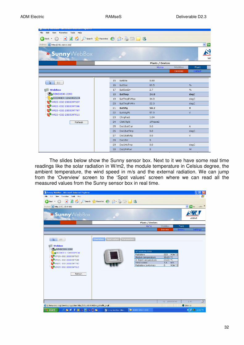
The slides below show the Sunny sensor box. Next to it we have some real time readings like the solar radiation in W/m2, the module temperature in Celsius degree, the ambient temperature, the wind speed in m/s and the external radiation. We can jump from the ‘Overview’ screen to the ‘Spot values’ screen where we can read all the measured values from the Sunny sensor box in real time.

ADM Electric RAMseS Deliverable D2.3
33
Note: detailed data archives, trends and analysis will the subject of future deliverables.