Embed Size (px)
Citation preview
11 Ninth Street ▪ Suite 120 ▪ Columbus, Georgia ▪ 31901 ▪ p. 706-571-6923 ▪ f. 706-571-6928
Sam Andras, AIA ▪ Georgia Registered Architect ▪ RA009353
MARCH 18, 2013 2WR of Georgia, Inc. Project No. 10-300 Troup County State Trooper Facility Columbus, Georgia ADDENDUM NO. 2 THIS ADDENDUM CONTAINS TWO (2) WRITTEN PAGES, TWELVE (12) 8 ½ X 11 ATTACHMENTS AND FIVE (5) 30 X 42 GRAPHIC PAGE ATTACHMENTS FOR A TOTAL OF NINETEEN (19) PAGES. THIS ADDENDUM FORMS A PART OF THE CONTRACT DOCUMENTS AS HEREIN DESCRIBED:
CLARIFICATION: Visit http://www.troupcountyga.org/media/GSP%20Invitation%20To%20Bid%20-%20REVISED%2025%20February%202013.pdf For InvitationTo Bid. This addendum modifies the contract documents. Many of the items listed within are not a part of the specific bid packages.
Contractors are cautioned to submit only bids for the Trade Bids listed therein.
1. HVAC (material and installation) 2. Fire Alarm (material and installation) 3. Fire Sprinkler (material and installation) 4. Glazing, Doors, HM Frames and Hardware (material only) Includes installed overhead door and
installed storefront 5. Millwork (material only) 6. Brick, Mortar and Accessories (material only) 7. Trusses (material only)
SPECIFICATIONS:
Item 2.1: Specification Section 04 2723 Unit Masonry Add Paragraph to 2.02 Brick Units, C. BR1: #370 Autumn-Blend by Taylor Clay Products; BR2: Wildwood – Queen by Boral Brick All brick shall be modular size. (Modifies item 1.1 issued under Addendum #1) Item 2.2: Not Used Item 2.3: Clean Agent Fire Suppression System, 8 pages attached. Price as Alternate installation of Clean Agent Fire Suppression System to Evidence Room. DRAWINGS:
Item 2.4: Sheet LS1.1 Life Safety Plan, revised 3/18/13, attached.
Clarify: Life Safety Plan has been revised to address comments from the Fire Marshal. This revised plan supersedes the previously revised plan issued under Addendum #1.

11 Ninth Street ▪ Suite 120 ▪ Columbus, Georgia ▪ 31901 ▪ p. 706-571-6923 ▪ f. 706-571-6928
Sam Andras, AIA ▪ Georgia Registered Architect ▪ RA009353
Item 2.5: Sheet A1.1 Floor Plan, Revise window designations in rooms 122, 120, 119, 117, 115, and 114, revised wall construction on rear wall of kitchen range, and new cabinet arrangement as shown on Sheet ASD 2.5 dated 3/18/13, attached. Item 2.6: Elevation 2/A8.1 Kitchen Area, Revise wall construction on rear wall of kitchen range, and new base and wall cabinet arrangement as shown on Sheet ASD 2.6 dated 3/18/13, attached.
Item 2.7: Elevation 2/A8.1 Kitchen Area, Revise base and wall cabinet arrangement as shown on Sheet ASD 2.7 dated 3/18/13, attached. Item 2.8: Window Elevation Sheet A9.1 Add Window Type C (Out-swinging Emergency Egress Casement Window) as shown on Sheet ASD 2.8 dated 3/18/13, attached. Not part of bid packages.
Item 2.9: Sheet A9.1 Door Schedule, Revise door schedule as shown on Sheet ASD 2.9 dated 3/18/13, attached.
Item 2.10: Sheet FP1.0 Floor Plan Fire Protection, revised 3/18/13, attached. Price as Alternate to include Clean Agent Fire Suppression System in Evidence Room. Item 2.11: Sheet FP2.0 Fire Protection Schedule & Details, revised 3/18/13, attached. Price as Alternate to include Clean Agent Fire Suppression System in Evidence Room.
Item 2.12: Sheet M1.0 Floor Plan Mechanical, revision 2 dated 3/15/13, attached. Base bid to include exhaust and make up air with damper in Evidence Room. Item 2.13: Sheet M2.0 Mechanical Schedules & Details, revision 2 dated 3/15/13, attached. Base bid to include exhaust and make up air with damper in Evidence Room.
END OF ADDENDUM NO. 2

10-300 Troup County State Highway Patrol Office
Construction Documents
15 March, 2013
CLEAN AGENT FIRE SUPPRESSION SYSTEM 1
1.1 CLEAN AGENT FIRE-SUPPRESSION SYSTEM
A. Scope:
This specification outlines the requirements for a "Total Flood" Clean Agent Fire Suppression System with automatic detection and control. The work described in this specification includes all engineering, labor, materials, equipment and service necessary, and required, to complete and test the suppression system. 1. Provide ANSUL Sapphire fire suppression system per NFPA Standards 2001 and 72-E
and all State and local codes. Provide contacts for fire alarm monitoring, cabinet, detectors, ceiling nozzles, and all equipment necessary for complete fire suppression package. Contractor will provide and install all equipment and accessories required for system installation. Contacts required for fire alarm monitoring areas as follows: a. Contact to signal the existing fire alarm system of activation of the fire suppression
system. b. Contact to monitor for power failure in the fire suppression system. c. Contact to monitor failure of the fire suppression system. d. Contact to monitor smoke damper failure of the fire suppression system.
B. Applicable Standards and Publications 1. The design, equipment, installation, testing and maintenance of the Clean Agent
Suppression System shall be in accordance with the applicable requirements set forth in the latest edition of the following codes and standards: a. National Fire Protection Association (NFPA) Standards: b. NFPA 2001 Clean Agent Fire Extinguishing Systems c. NFPA 70 National Electric Code d. NFPA 72 National Fire Alarm Code e. Factory Mutual Systems (FM) Publications f. Factory Mutual Approval Guide g. Underwriters Laboratories, Inc. (UL) Publication h. Fire Protection Equipment Directory with quarterly supplements i. National Electrical Manufacturers Association (NEMA) Publication j. Enclosures for Industrial Controls and Systems k. U.S. Environmental Protection Agency, Protection of Stratospheric Ozone 59 FR
13044 (SNAP) l. Requirements of the Authority Having Jurisdiction (AHJ), University, State and
Local codes in force at time of award of contract. 2. The standards listed, as well as all other applicable codes, standards, and good
engineering practices, shall be used as “minimum" design standards.
C. Requirements 1. The Suppression System installation shall be made in accordance with the drawings,
specifications, and applicable standards. Should a conflict occur between the drawings and specifications, the specifications shall prevail. All conflicts shall be in writing to Engineer.
D. The work listed below shall be provided by UNDER THIS CONTRACT,: 1. 120 VAC or 220 VAC power supply to the system control panel -. 2. Interlock wiring and conduit for shutdown of HVAC, dampers and/or electric power
supplies, relays or shunt trip breakers.
E. Manufacturer
10-300 Troup County State Highway Patrol Office
Construction Documents
15 March, 2013
CLEAN AGENT FIRE SUPPRESSION SYSTEM 2
1. The manufacturer of the suppression system hardware and detection components shall be ISO 9001 registered.
2. The name of the manufacturer shall appear on all major components. 3. All devices, components, and equipment shall be the products of the same
manufacturer, or supplied by the same manufacturer. 4. All devices, components, and equipment shall be new, standard products of the
manufacturer's latest design and suitable to perform the functions intended. 5. All devices and equipment shall be UL listed and/or FM approved. 6. Locks for all cabinets shall be keyed alike.
F. Installer 1. The installing contractor shall be trained by the supplier to design, install, test, and
maintain fire suppression systems. 2. The installing contractor (for Clean Agent System) shall employ a NICET certified special
hazard designer, Level III or above, who will be responsible for this project. 3. The installing contractor shall be an experienced firm regularly engaged in the installation
of automatic clean agent, or similar, fire suppression systems, in strict accordance with all applicable codes and standards.
4. The installing contractor must have a minimum of five (5) years experience in the design, installation, and testing, of clean agent, or similar fire suppression systems. A list of systems of a similar nature and scope shall be provided on request.
5. The installing contractor shall show evidence that his company carries a minimum liability insurance required by Auburn University and completed operations insurance policy. These limits shall supersede limits required in the general conditions of the specifications.
6. The installing contractor shall maintain, or have access to, a clean agent recharging station. The installing contractor shall provide proof of his ability to recharge the largest clean agent system within 24 hours after a discharge. Include the amount of bulk agent storage available.
7. The installing contractor shall be an authorized stocking distributor of the clean agent system equipment so that immediate replacement parts are available from inventory.
8. The installing contractor shall show proof of emergency service available on a 24/7 - 7 days basis.
G. Submittals 1. The installing contractor shall submit the following design information and drawings for
approval prior to starting work on this project: a) Field installation layout drawings having a scale of not less than 1/4 in. = 1 ft 0 in.
or 1:100 detailing the location of all agent storage tanks, nozzles, pipe runs, including pipe sizes and lengths, control panel(s), detectors, manual pull stations, abort stations, audible and visual alarms, etc.
b) Auxiliary details and information such as maintenance panels, door holders, special sealing requirements, and equipment shutdown.
c) Separate layouts, or drawings, shall be provided for each level, (i.e.; room, sub floor, and above ceiling) and for mechanical and electrical work.
d) Electrical layout drawings shall show the location of all devices and include pointpoint conduit runs and a description of the method(s) used for detector mounting.
e) Provide an internal control panel wiring diagram which shall include power supply requirements and field wiring termination points.
f) Separate drawing providing symbol legend and identifying all symbols used. g) Annunciator wiring schematics and dimensioned display panel illustration shall
be provided. h) Complete hydraulic flow calculations, from a UL listed computer program, shall
be provided for all engineered clean agent systems. Calculation sheet(s) must include the manufacturer’s name and UL listing number for verification. The
10-300 Troup County State Highway Patrol Office
Construction Documents
15 March, 2013
CLEAN AGENT FIRE SUPPRESSION SYSTEM 3
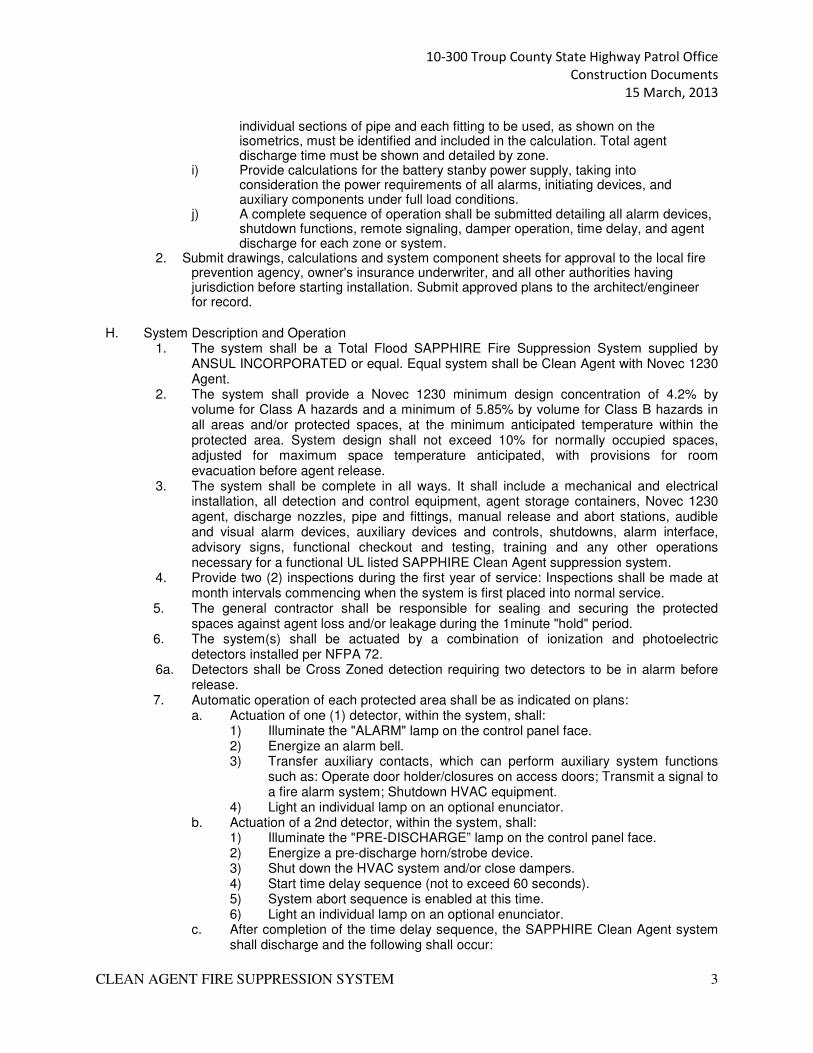
individual sections of pipe and each fitting to be used, as shown on the isometrics, must be identified and included in the calculation. Total agent discharge time must be shown and detailed by zone.
i) Provide calculations for the battery stanby power supply, taking into consideration the power requirements of all alarms, initiating devices, and auxiliary components under full load conditions.
j) A complete sequence of operation shall be submitted detailing all alarm devices, shutdown functions, remote signaling, damper operation, time delay, and agent discharge for each zone or system.
2. Submit drawings, calculations and system component sheets for approval to the local fire prevention agency, owner's insurance underwriter, and all other authorities having jurisdiction before starting installation. Submit approved plans to the architect/engineer for record.
H. System Description and Operation 1. The system shall be a Total Flood SAPPHIRE Fire Suppression System supplied by
ANSUL INCORPORATED or equal. Equal system shall be Clean Agent with Novec 1230 Agent.
2. The system shall provide a Novec 1230 minimum design concentration of 4.2% by volume for Class A hazards and a minimum of 5.85% by volume for Class B hazards in all areas and/or protected spaces, at the minimum anticipated temperature within the protected area. System design shall not exceed 10% for normally occupied spaces, adjusted for maximum space temperature anticipated, with provisions for room evacuation before agent release.
3. The system shall be complete in all ways. It shall include a mechanical and electrical installation, all detection and control equipment, agent storage containers, Novec 1230 agent, discharge nozzles, pipe and fittings, manual release and abort stations, audible and visual alarm devices, auxiliary devices and controls, shutdowns, alarm interface, advisory signs, functional checkout and testing, training and any other operations necessary for a functional UL listed SAPPHIRE Clean Agent suppression system.
4. Provide two (2) inspections during the first year of service: Inspections shall be made at month intervals commencing when the system is first placed into normal service.
5. The general contractor shall be responsible for sealing and securing the protected spaces against agent loss and/or leakage during the 1minute "hold" period.
6. The system(s) shall be actuated by a combination of ionization and photoelectric detectors installed per NFPA 72.
6a. Detectors shall be Cross Zoned detection requiring two detectors to be in alarm before release.
7. Automatic operation of each protected area shall be as indicated on plans: a. Actuation of one (1) detector, within the system, shall:
1) Illuminate the "ALARM" lamp on the control panel face. 2) Energize an alarm bell. 3) Transfer auxiliary contacts, which can perform auxiliary system functions
such as: Operate door holder/closures on access doors; Transmit a signal to a fire alarm system; Shutdown HVAC equipment.
4) Light an individual lamp on an optional enunciator. b. Actuation of a 2nd detector, within the system, shall:
1) Illuminate the "PRE-DISCHARGE” lamp on the control panel face. 2) Energize a pre-discharge horn/strobe device. 3) Shut down the HVAC system and/or close dampers. 4) Start time delay sequence (not to exceed 60 seconds). 5) System abort sequence is enabled at this time. 6) Light an individual lamp on an optional enunciator.
c. After completion of the time delay sequence, the SAPPHIRE Clean Agent system shall discharge and the following shall occur:
10-300 Troup County State Highway Patrol Office
Construction Documents
15 March, 2013
CLEAN AGENT FIRE SUPPRESSION SYSTEM 4
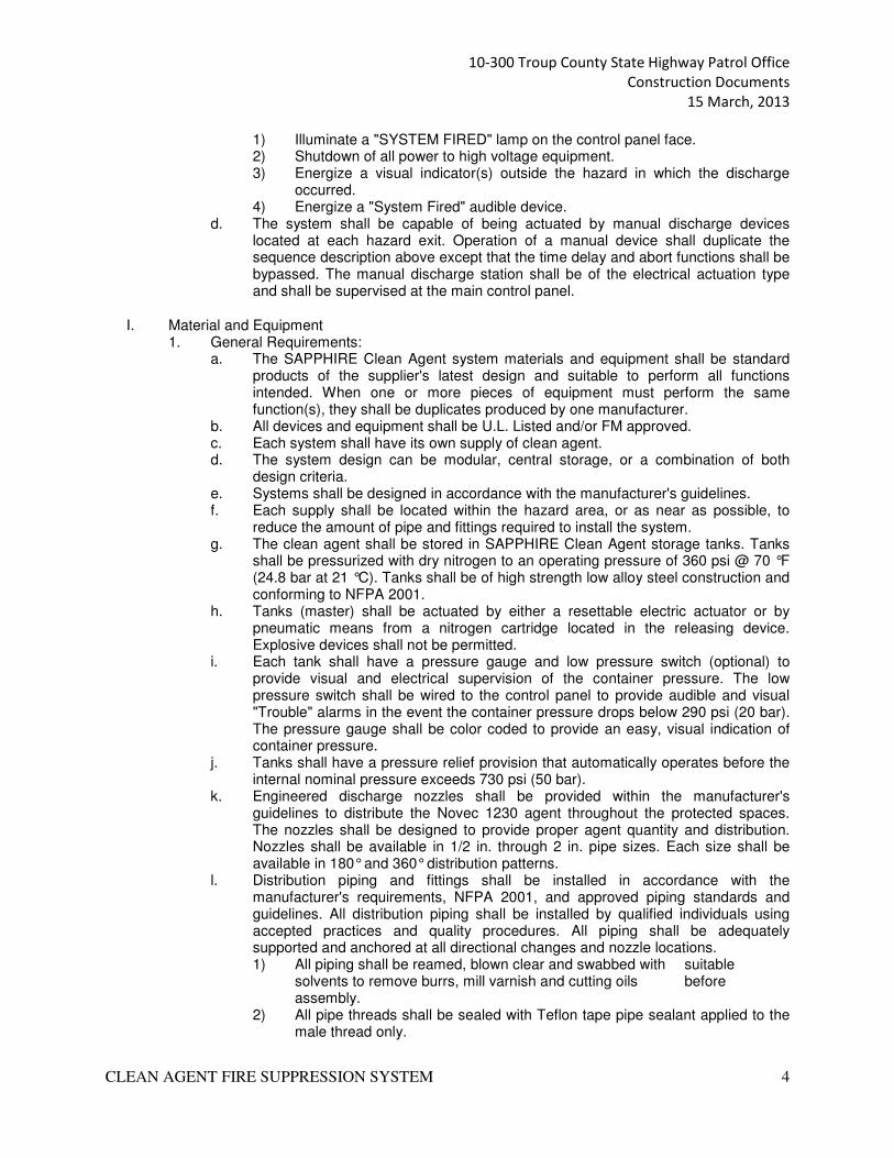
1) Illuminate a "SYSTEM FIRED" lamp on the control panel face. 2) Shutdown of all power to high voltage equipment. 3) Energize a visual indicator(s) outside the hazard in which the discharge
occurred. 4) Energize a "System Fired" audible device.
d. The system shall be capable of being actuated by manual discharge devices located at each hazard exit. Operation of a manual device shall duplicate the sequence description above except that the time delay and abort functions shall be bypassed. The manual discharge station shall be of the electrical actuation type and shall be supervised at the main control panel.
I. Material and Equipment 1. General Requirements:
a. The SAPPHIRE Clean Agent system materials and equipment shall be standard products of the supplier's latest design and suitable to perform all functions intended. When one or more pieces of equipment must perform the same function(s), they shall be duplicates produced by one manufacturer.
b. All devices and equipment shall be U.L. Listed and/or FM approved. c. Each system shall have its own supply of clean agent. d. The system design can be modular, central storage, or a combination of both
design criteria. e. Systems shall be designed in accordance with the manufacturer's guidelines. f. Each supply shall be located within the hazard area, or as near as possible, to
reduce the amount of pipe and fittings required to install the system. g. The clean agent shall be stored in SAPPHIRE Clean Agent storage tanks. Tanks
shall be pressurized with dry nitrogen to an operating pressure of 360 psi @ 70 °F (24.8 bar at 21 °C). Tanks shall be of high strength low alloy steel construction and conforming to NFPA 2001.
h. Tanks (master) shall be actuated by either a resettable electric actuator or by pneumatic means from a nitrogen cartridge located in the releasing device. Explosive devices shall not be permitted.
i. Each tank shall have a pressure gauge and low pressure switch (optional) to provide visual and electrical supervision of the container pressure. The low pressure switch shall be wired to the control panel to provide audible and visual "Trouble" alarms in the event the container pressure drops below 290 psi (20 bar). The pressure gauge shall be color coded to provide an easy, visual indication of container pressure.
j. Tanks shall have a pressure relief provision that automatically operates before the internal nominal pressure exceeds 730 psi (50 bar).
k. Engineered discharge nozzles shall be provided within the manufacturer's guidelines to distribute the Novec 1230 agent throughout the protected spaces. The nozzles shall be designed to provide proper agent quantity and distribution. Nozzles shall be available in 1/2 in. through 2 in. pipe sizes. Each size shall be available in 180° and 360° distribution patterns.
l. Distribution piping and fittings shall be installed in accordance with the manufacturer's requirements, NFPA 2001, and approved piping standards and guidelines. All distribution piping shall be installed by qualified individuals using accepted practices and quality procedures. All piping shall be adequately supported and anchored at all directional changes and nozzle locations. 1) All piping shall be reamed, blown clear and swabbed with suitable
solvents to remove burrs, mill varnish and cutting oils before assembly.
2) All pipe threads shall be sealed with Teflon tape pipe sealant applied to the male thread only.
10-300 Troup County State Highway Patrol Office
Construction Documents
15 March, 2013
CLEAN AGENT FIRE SUPPRESSION SYSTEM 5
2. Agent a. The fire suppression agent shall be 3M™ Novec™ 1230 Fire Protection
Fluid manufactured by 3M Company, St. Paul, MN or their approved supplier.
b. Agent shall not contain any Hydrofluorocarbons (HFC). 3. Control Panel
a. The control panels shall be a laser scanner releasing panel supplied by ANSUL INCORPORATED.
b. The detection control system and its components shall be UL listed and FM approved for use as a local fire alarm system with releasing device service.
c. The control system shall perform all functions necessary to operate the system detection, actuation, and auxiliary functions.
d. The control system shall include battery standby power to support 24 hours in standby and 5 minutes in alarm.
e. The control system shall be microprocessor based, utilizing a distributed processing concept. A single microprocessor failure shall not impact operation of additional modules in the system.
f. The control system shall be capable of supporting Cross Zoned Detection. g. The control system shall supply integrated 2.0 amp (minimum) power supply
circuitry. h. Each control system shall contain four (4) initiating circuits:
1) Each circuit shall be capable of Class A (Style D) or Class B (Style A) operation.
2) Each circuit shall be capable of operating up to fifteen (15) approved detectors or thirty (30) detectors per system.
3) Each circuit shall be capable of monitoring contact devices configured for manual release, manual alarm, system abort, trouble input or auxiliary (nofire) input.
i. Each control system shall contain release circuits for activation of a fire suppression system(s): 1) Each circuit shall be capable of Class B (Style Y) operation. 2) Each circuit shall be rated for a minimum of 1.5 amp @ 24 VDC.
j. Each control system shall contain two (2) indicating appliance circuits for annunciation: 1) Each circuit shall be capable of Class A (Style B) or Class B (StyleY)
operation. 2) Each circuit shall be rated for a minimum of 1.5 amp @ 24 VDC.
k. Each control system shall provide an auxiliary power supply rated for 2 amps @ 24 VDC.
l. Each control system shall provide two (2) SPST relays: one for common alarm and one for common trouble. Four (4) additional programmable relays can be added to each control system by adding a relay module.
4. Detectors a. The detectors shall be spaced and installed in accordance with the manufacturer's
specifications and the guidelines of NFPA 72. b. The ionization detector shall be an Ansul model. (Refer to Electrical) c. The photoelectric detector shall be an Ansul model. (Refer to Electrical)
5. Manual Release (Electric) a. The electric manual release shall be a dual action device which provides a means
of manually discharging the suppression system when used in conjunction with the detection system.
b. The manual release shall be an Ansul model. c. The manual release or manual pull station shall be a dual action device requiring
two distinct operations to initiate a system actuation.
10-300 Troup County State Highway Patrol Office
Construction Documents
15 March, 2013
CLEAN AGENT FIRE SUPPRESSION SYSTEM 6
d. Manual actuation shall bypass the time delay and abort functions and shall cause all release and shutdown devices to operate in the same manner as if the system had operated automatically.
e. Manual release shall be located at each exit from the protected hazard.
6. Abort Station a. The optional abort station shall be the "Dead Man" type and shall be located next
to each manual release. b. The abort station shall be an Ansul model. c. The abort station shall be supervised and shall indicate a trouble condition at the
control panel, if depressed, and no alarm condition exists. d. "Locking" or "Keyed" abort stations shall not be permitted.
7. Audible and Visual Alarms a. Alarm audible and visual signal devices shall operate from the control panel. b. The alarm bell, alarm horn, and horn strobe devices shall be an Ansul model. c. The visual alarm unit shall be an Ansul strobe device. d. A strobe device shall be placed outside, and above, each exit door from the
protected space. Provide an advisory sign at each light location. 8. Caution and Advisory Signs: Signs shall be provided to comply with NFPA 2001 and the
recommendations of the SAPPHIRE equipment provider. a. Entrance sign: (1) required at each entrance to a protected space b. Manual discharge sign: (1) required at each manual release station. c. Flashing light sign: (1) required at each flashing light over each exit from a
protected space. 9. System and Control Wiring:
a. All system wiring shall be furnished and installed by the contractor. b. All wiring shall be installed in electrical metallic tubing (EMT), or conduit, and must
be installed and kept separate from all other building wiring. c. All system components shall be securely supported independent of the wiring.
Runs of conduit and wiring shall be straight, neatly arranged, properly supported, and installed parallel and perpendicular to walls and partitions.
d. The sizes of the conductors shall be those specified by the manufacturer. Color coded wire shall be used. All wires shall be tagged at all junction points and shall be free from shorts, earth connections (unless so noted on the system drawings), and crosses between conductors. Final terminations between the control panel and the system field wiring shall be made under the direct supervision of a factory trained representative.
e. All wiring shall be installed by qualified individuals, in a neat and workmanlike manner, to conform to the National Electrical Code, Article 725 and Article 760, except as otherwise permitted for limited energy circuits, as described in NFPA 72. Wiring installation shall meet all local, state, province, and/or country codes.
f. The complete system electrical installation and all auxiliary components shall be connected to earth ground in accordance with the National Electrical Code.
J. System Inspection and Checkout - After the system installation has been completed, the entire system shall be checked out, inspected, and functionally tested by qualified, trained personnel, in accordance with the manufacturer's recommended procedures and NFPA standards. See Inspection Section 1.5. 1. All containers and distribution piping shall be checked for proper mounting and
installation.
10-300 Troup County State Highway Patrol Office
Construction Documents
15 March, 2013
CLEAN AGENT FIRE SUPPRESSION SYSTEM 7
2. All electrical wiring shall be tested for proper connection, continuity and resistance to earth.
3. The complete system shall be functionally tested, in the presence of the owner or his representative, and all functions, including system and equipment interlocks, must be operational at least five (5) days prior to the final Acceptance tests.
4. Each detector shall be tested in accordance with the manufacturer's recommended procedures and test values recorded.
5. All system and equipment interlocks, such as door release devices, audible and visual devices, equipment shutdowns, local and remote alarms, etc. shall function as required and designed.
6. Each control panel circuit shall be tested for trouble by inducing a trouble condition into the system.
K. Training Requirements: 1. Prior to final acceptance, the installing contractor shall provide operational training to
each shift of the owner’s personnel. Each training session shall include control panel operation, manual and abort functions, trouble procedures, supervisory procedures, auxiliary functions and emergency procedures.
L. Operation and Maintenance: 1. Prior to final acceptance, the installing contractor shall provide four (4) complete
operation and maintenance instruction manuals to the owner. All aspects of system operation and maintenance shall be detailed, including piping isometrics, wiring diagrams of all circuits, a written description of the system design, sequence of operation and drawing(s) illustrating control logic and equipment used in the system. Checklists and procedures for emergency situations, troubleshooting techniques, maintenance operations, trained personnel and procedures shall be included in the manual.
M. Acceptance Test: 1. At the time "As-Built" drawings and maintenance/operations manuals are submitted, the
installing contractor shall submit a "Test Plan" describing procedures to be used to test the control system(s). The Test Plan shall include a step by step description of all tests to be performed and shall indicate the type and location of test apparatus to be employed. The tests shall demonstrate that the operational and installation requirements of this specification have been met. All tests shall be conducted in the presence of the owner and shall not be conducted until the Test Plan has been approved.
2. The tests shall demonstrate that the entire control system functions as designed and intended. All circuits shall be tested: automatic actuation and manual actuation, HVAC and power shutdowns, audible and visual alarm devices, and manual override of abort functions. Supervision of all panel circuits, including AC power and battery power supplies, shall be tested and qualified.
3. A room pressurization test shall be conducted in each protected space to determine the presence of openings, which would affect the agent concentration levels. The test(s) shall be conducted using the RetrTec Corp. Door Fan system, or equivalent, with integrated computer program. All testing shall be in accordance with NFPA 2001.
4. If room pressurization testing indicates that openings exist which would result in leaks and/or loss of the extinguishing agent, the installing contractor shall be responsible for coordinating the proper sealing of the protected space(s) by the general contractor or his subcontractor or agent. The general contractor shall be responsible for adequately sealing all protected space(s) against agent loss or leakage. The installing contractor shall inspect all work to ascertain that the protected space(s) have been adequately and properly sealed. THE SUPPRESSION SYSTEM INSTALLING CONTRACTOR SHALL BE RESPONSIBLE FOR THE SUCCESS OF THE ROOM PRESSURIZATION TESTS. If the first room pressurization test is not successful, in accordance with these
10-300 Troup County State Highway Patrol Office
Construction Documents
15 March, 2013
CLEAN AGENT FIRE SUPPRESSION SYSTEM 8
specifications, the installing contractor shall direct the general contractor to determine, and correct, the cause of the test failure. The installing contractor shall conduct additional room pressurization tests, at no additional cost to the owner, until a successful test is obtained. Copies of successful test results shall be submitted to the owner for his record. Upon acceptance by the owner, the completed system(s) shall be placed into service.
N. System Inspections: 1. During the one year warranty period, the installing contractor shall provide two (2)
inspections of each system installed under this contract. The first inspection shall be at the six month interval, and the second inspection at the 1month interval. Inspections shall be conducted in accordance with the manufacturer's guidelines and the recommendations of NFPA 2001.
2. Documents certifying satisfactory system(s) inspection shall be submitted to the owner upon completion of each inspection.
O. Warranty: 1. All Ansul system components furnished and installed under this contract shall be
warranted against defects in design, materials and workmanship for the full warranty period which is standard with the manufacturer, but in no case less than one (1) year from the date of system acceptance.
P. The proper operation and coordination for the system's installation, including the automatic sprinkler system, detection system, signaling system and initial start-ups are all under the responsibility of the fire protection contractor.
637 SF
LOUNGE123
P=42
423 SF
CONFERENCE101
P=29
GROUP R-31285 SF
GROUP B4729 SF
GROUP S-1PRIVATE VEHICLES4155 SF
GROUP S-11012 SF
78 SF
STORAGE145
132 SF
BED115
P=1
132 SF
BED117
P=1
223 SF
BED122
P=2196 SF
BED119
P=1
121 SF
LOCKER114
P=1
191 SF
OFFICE112
P=2
134 SF
OFFICE111
P=2134 SF
OFFICE110
P=2
179 SF
RECEPTION124
P=2150 SF
LOBBY126
P=2
92 SF
INTERVIEW128
P=1
407 SF
WORK106
P=5
155 SF
OFFICE133
P=2155 SF
OFFICE135
P=2112 SF
OFFICE132
P=2
DEAD END CORRIDOR: 19'-8"
177 SF
INMATE142
P=1
EGRESS CAPACITY: 118BREQUIRED: 27 OCCUPANTS x .02 IN / OCCUPANT = 5.4 INCHESPROVIDED: 34 INCHES CLEAR
EGRESS CAPACITY: 126AREQUIRED: 2 OCCUPANTS x .2 INCHES / OCCUPANT = .4 INCHESPROVIDED: 68 INCHES CLEAR
EGRESS CAPACITY: DOOR 107REQUIRED: 36 OCCUPANTS x .2 INCHES / OCCUPANT = 7.2 INCHESPROVIDED: 34 INCHES CLEAR
EGRESS CAPACITY: DOOR 147AREQUIRED: 36 OCCUPANTS x .2 INCHES / OCCUPANT = 7.2 INCHESPROVIDED: 34 INCHES CLEAR
EGRESS CAPACITY: DOOR 142REQUIRED: 1 OCCUPANTS x .2 INCHES / OCCUPANT = .2 INCHESPROVIDED: 34 INCHES CLEAR
FEC
FEC
FEC
15 14 FEC
FE
@ 1:15
@ 1:15
2 HR RATED FLOOR/ CEILING @ BOTTOMOF CHORD (UL DESIGN L 211)
THESE WALLS MUST BE OF NON-COMBUSTIBLE CONSTRUCTION - 3 5/8"METAL STUDS W/ DENS GLASS, DUROCK OR CENTITIOUS BOARD APPLIEDTO BOTH SIDES PER NFPA 96 AND GEORGIA STATE AMENDMENTS.
(NO OCCUPANTS REQ. PER NFPA 101)
2 HR RATED WALL IN ATTIC
SUBJECT APPLICABLE CODE NOTES CITATION1
2
3
4
5
6
7
8
9
10
11
OCCUPANCYCLASSIFICATION
OFFICE SPACE - BSLEEPING ROOMS - R-3STORAGE - S-1
LSC - PRIMARYIBC - SUPPLEMENT
BUILDING AREA IBC - PRIMARYLSC - SUPPLEMENT
OCCUPANCY B - OFFICE SPACE - 4729 SF (9,000 SF ALLOWED)OCCUPANCY R-3 - SLEEPING ROOMS - 1285 SF (UL SF ALLOWED)OCCUPANCY S-1 - GARAGE - 4155 SF + 1012 ACCESSORY (9,000 ALLOWED)
CONSTRUCTIONTYPE
IBC - PRIMARYLSC - SUPPLEMENT
TYPE V (0,0,0)TYPE VB (SPRINKLERED)
OCCUPANCYSEPARATION
IBC - PRIMARYLSC - SUPPLEMENT
NUMBER OFSTORIES
IBC - PRIMARYLSC - SUPPLEMENT
OCCUPANCY B - OFFICE SPACE - 1 STORY (2 ALLOWED)OCCUPANCY R-3 - SLEEPING ROOMS- 1 STORY (3 ALLOWED)OCCUPANCY S-1 - STORAGE - 1 STORY (1 ALLOWED)
BUILDING HEIGHT IBC - PRIMARYLSC - SUPPLEMENT
TYPE VB - 22 FEET (40 ALLOWED)
OCCUPANT LOAD LSC TOTAL = 99 OCCUPANTS
DEAD-ENDCORRIDORS
LSC NEW BUSINESS - 50 FEET MAXNEW ROOMING HOUSE - NANEW STORAGE - 50 FEET MAX
CORRIDORPROTECTION
LSC NEW BUSINESS - NONE REQUIRED
NEW LODGING - SMOKE PROTECTED
NFPA 10112.3.6 (EXCEPTION 1)
NFPA 10126.3.4
NFPA 101: 38.2.5.2
NFPA 101:TABLE 7.3.1.2
IBC: TABLE 508.3.3
IBC: TABLE 503
IBC: TABLE 503
IBC: TABLE 503
IBC: 602.5
NFPA 101:TABLE 7.3.1.2IBC: 303 & 304
COMMON PATHOF TRAVEL
LSC NEW BUSINESS - 100 FEETR3 - NO REQUIREMENT
NFPA 101: 38.2.5.2
TRAVEL DISTANCE LSC NEW BUSINESS - 300 FEETR3 - NO REQUIREMENT
NFPA 101: 38.2.6
12
13
14
15
16
17
18
19
20
21
22
23
FIRE RATEDMECHANICALAND STORAGE
IBC STORAGE - (1) HOUR IF OVER 100 SF - PROVIDED AROUND EVIDENCE 104 AND GARAGE 141MECHANICAL - (1) HOUR
TABLE 508.3
STANDPIPES LSC - PRIMARYIBC - SUPPLEMENT
- -
INTERIOR FINISHES LSC - -
HVAC SYSTEM LSC FIRE DAMPER IN RATED WALL / SMOKE DAMPER IN SMOKE PARTITION -
SPRINKLER SYSTEM LSC - PRIMARYIBC - SUPPLEMENT
SPRINKLERED IN LODGING AREASPRINKLERED IN BUSINESSDRY PIPE SYSTEM IN ATTIC - SEE FP DWGS
-
FIRE ALARM SYSTEM LSC NOT REQUIRED FOR BUSINESS OCCUPANCY UNDER 300 TOTALOCCUPANTS BUT REQUIRED IN LODGING.
NFPA 101: 38.3.4.1NFPA 101: 26.3.5.2
SMOKE ALARMS STATE STATUTE & LSC REQUIRED IN EACH SLEEPING ROOM -
PORTABLE FIREEXTINUISHERS
IFC REQUIRED. TRAVEL DISTANCE NO MORE THAN 75 FEET IFC: TABLE 906.3 (1)
COOKING EQUIP. LSC AND NFPA 96 COMMERCIAL HOOD W/ FIRE SUPPRESSION SYSTEM ABOVE KITCHEN RANGE
FUEL FIREDAPPLIANCES
IFGC - PRIMARYNFPA 54 - SUPPLEMENT
N/A
LIQUID PETROLEUMGA
NFPA 58 - PRIMARYNFPA 54 OR IFGC -SUPPLEMENT
-
COMMPRESSEDNATURAL GA
NFPA 52 -
SUBJECT APPLICABLE CODE NOTES CITATION
BETWEEN BUSINESS AND RESIDENTIAL - 1 HOUR WITH APPROVED SPRINKLER SYSTEMBETWEEN BUSINESS AND S-2 - 1 HOUR (EXCEPTION C - PRIVATE VEHICLES)BETWEEN BUSINESS AND S-1 - 1 HOUR IF OVER 100 SFBETWEEN S-1 AND S-2 - 2 HOUR W/O SPRINKLER SYSTEM
Room name101
150 SFP=20 ROOM OCCUPANT LOAD
SMOKE PARTITION
1-HOUR FIRE RATED WALL - SEE 1/A6.1
FEC FIRE EXTINGUISHER CABINET
EXIT DISCHARGE
START OF PATH OF TRAVEL -MOST REMOTE POINT IN SPACE
ROOM EXIT - MERGE WITH PATH OF EGRESS
EXIT SIGN
FE FIRE EXTINGUISHER CABINET
2-HOUR FIRE RATED WALL - SEE 4/A6.1
Date:
Drawn By:
Project Number:
2WRarchitecture l interiors l planning l landscape
11 Ninth StreetSuite 120Columbus, GA 31901p. 706.571.6923f. 706.571.6928
Revisions:
Sheet Description
Sheet Number
FOETATS
AIGROEG
D ARCHITE
CTR
EG
ISTERE
SAMANDRAS009353
Checked By:
LS1.1
LIFE SAFETYPLAN
TROUP COUNTY, GEORGIA
TROUPCOUNTY STATE
PATROLOFFICE
JM, JS, EA
31 OCTOBER 2012
10-300
ADDENDUM 2
MS
SCALE: 1/8" = 1'-0"LS1.1
1 LIFE SAFETY PLAN
LIFE SAFETY LEGEND
2
No. Date Description
1 02/27/2013 Revision.
2 03/15/2013 Revision.
2
2
2
2
IBC TABLE 503 - GROUP B
TYPE V CONSTRUCTION = 9,000 SF ALLOWED
AUTOMATIC SPRINKLER SYSTEM ALLOWABLE AREAINCREASE = +200% = 27,000 SF ALLOWED
NFPA 101 - SPECIAL PROVISIONS FOR PARKINGSTRUCTURES 42.8 - ORDINARY HAZARD
4155 SF PARKING + 1012 SF ACCESSORY = 5,167 SF
1 HR FIRE-RATED SEPARATION REQUIRED BETWEENPARKING AND REPAIR SECTIONS.
EMERGENCY LIGHTING REQUIRED.
NO FUEL DISPENSING.
DEAD END CORRIDOR MAX. = 50 FTTRAVEL DISTANCE TO EXIT MAX. = 400 FT
NFPA 101 - NEW BUSINESS OCCUPANCY
4,729 SF, SPRINKLERED
2 HR FIRE-RATED WALLS SEPARATING PARKINGSTRUCTURES REQUIRED. NON-RATED GLAZING ANDNON-RATED OPENING PROTECTIVES PERMITTEDPER EXCEPTIONS.
LIGHT HAZARD NFPA 13 AUTOMATIC SPRINKLERSYSTEM.
ORDINARY HAZARD CONTENTS.
AREAS OF REFUGE NOT REQUIRED.
SINGLE EXIT ALLOWED - 3 EXITS PROVIDED
MINIMUM CORRIDOR WIDTH = 44 INDEAD END CORRIDOR MAX. = 50 FTTRAVEL DISTANCE TO EXIT MAX. = 300 FTCOMMON PATH OF TRAVEL PERMITTED FOR THEFIRST 100 FT.CORRIDORS NOT RATED PER EXCEPTION - NFPA38.3.6.1
NFPA 101 - NEW RESIDENTIAL BOARD AND CARE
1285 SF, SPRINKLEREDSMALL FACILITY (LESS THAN 16 RESIDENTS)
2 HR FIRE-RATED SEPARATION REQUIRED.
EVACUATION CAPABILITY = PROMPT. NOT LESSTHAN 2 REMOTELY LOCATED MEANS OF EGRESSREQUIRED. SECONDARY MEANS OF ESCAPE FROMSLEEPING AREA MAY BE THROUGH THROUGHOUTSIDE WINDOW.
MANUAL FIRE ALARM SYSTEM REQUIRED.
OCCUPANT NOTIFICIATION SYSTEM (AUTOMATIC) ISREQUIRED.
SMOKE ALARMS NOT REQUIRED IN SPRINKLEREDBUILDINGS - NFPA 32.2.3.4.3.1 EXCEPTION.DOOR CLOSERS NOT REQURED IN SMOKEPARTITIONS.
QUICK RESPONSE RESIDENTIAL SPRINKLERSREQUIRED.
CORRIDOR WALLS = 1/2 HOUR FIRE-RATED OREXCEPTION 1.
EMERGENCY EVACUATION PLAN REQUIRED.
TOTAL AREA: 11181 SF
2
WD
119
111110
OFFICE111
OFFICE112
LOCKER114
BED115
TOILET116
BED117
BED119
TOILET121
BED122
CORRIDOR118
117115
122
120
116A
TOILET120
116B
KITCHENAREA
LOUNGE123
14' - 6"
A2.14
5' -
1"
4' - 10" 11' - 7"
112114
113
WASHER / DRYER113
CLOSET112A
118B1
CORRIDOR109
4' -
7"14' - 11"
12' - 7"
16' -
7"
144
PANTRY144
DW
A8.1
6
123
4' - 0" 5' -
4"
118A
121
148
STORAGE148
A8.11
A2.13
3' -
0"
A6.73
112A
5' -
1"13
' - 1
1"
3
3
4
10
4' -
0"
A A
C C C C
CCC
A A
13' -
0"
13
12
14
5' -
8"
17 17
17
17
14
25
25
REF
REF
ASD 2.61
ASD 2.7
1
Date:Drawn By:
Project Number:2WRarchitecture l interiorsplanning l landscape
11 Ninth StreetSuite 120Columbus, GA 31901p. 706.571.6923f. 706.571.6928
Revisions: Sheet Description
Checked By: ASD 2.5REVISEDFLOORPLAN
(1/A1.1)TROUP COUNTY, GEORGIA
TROUP COUNTY STATEPATROL OFFICE EA
18 MARCH 2013
10-300
ADDENDUM 2
AG
SCALE: 1/8" = 1'-0"ASD2.5
1 FLOOR PLANTHIS PARTITION SHALL BE 3 5/8" METAL STUDS @ 16" O.C.W/ DUROCK OR OTHER NON-COMBBUSTIBLE MATERIAL.
ADD CONSTRUCTION NOTE:
25
No. Date

HOOD WITH FIRE SUPPRESSION(SEE MECH.)
BACKSPLASH
COUNTERTOP- PL2
DRAWER - PL1
BASE CABINET -PL1
RUBBER BASE -MATCH WALL BASE
RUBBER WALL BASE - RB1
CABINET,TYP. - PL1
DOOR HANDLE, TYP - SEEHARDWARE SCHED.
1
A8.2
REFRIDGERATOR (N.I.C.) PROVIDEPOWER AND WATER AS REQUIRED(SEE MECH.)
STOVE (N.I.C.) PROVIDE POWER ANDWATER AS REQUIRED (SEE MECH.)
1' -
3"4'
- 0"
3' -
0"
7' -
0"
9
METAL STUD FIRE-RATED WALL -SEE PLAN
Date:Drawn By:
Project Number:2WRarchitecture l interiorsplanning l landscape
11 Ninth StreetSuite 120Columbus, GA 31901p. 706.571.6923f. 706.571.6928
Revisions: Sheet Description
Checked By: ASD 2.6REVISEDKITCHEN
ELEVATION(2/A8.1)
TROUP COUNTY, GEORGIA
TROUP COUNTY STATEPATROL OFFICE EA
18 MARCH 2013
10-300
ADDENDUM 2
AG
SCALE: 1/2" = 1'-0"ASD2.6
1 KITCHEN AREA WEST ELEVATION
No. Date
CABINET DOOR, TYP - PL1
DOOR HANDLE, TYPSEE HARDWARE SCHED.
BACKSPLASH - PL2
COUNTERTOP - PL2
DRAWER, TYP - PL1
BASE CABINET, TYP - PL1BASE - MATCHWALL BASE
SINK
3
A8.2
1
A8.2
3' -
0"
FILLER PANEL ASREQUIRED, TYP - PL1
1' - 3" 2' - 6" 3' - 0"3' - 6"
1' - 0"
ALIG
N
ALIG
N
9
A3.1
Date:Drawn By:
Project Number:2WRarchitecture l interiorsplanning l landscape
11 Ninth StreetSuite 120Columbus, GA 31901p. 706.571.6923f. 706.571.6928
Revisions: Sheet Description
Checked By: ASD 2.7REVISEDKITCHEN
ELEVATION(3/A8.1)
TROUP COUNTY, GEORGIA
TROUP COUNTY STATEPATROL OFFICE EA
18 MARCH 2013
10-300
ADDENDUM 2
AG
SCALE: 1/2" = 1'-0"ASD2.7
1 KITCHEN AREA SOUTH ELEVATION
No. Date
1
6' -
0"2'
- 0"
3' - 0"
-
---
-
---
1
A9.4
2
A9.4
TYP.
5 @ ROOM 120
7/8" FALSE MUNTIN
Date:Drawn By:
Project Number:2WRarchitecture l interiorsplanning l landscape
11 Ninth StreetSuite 120Columbus, GA 31901p. 706.571.6923f. 706.571.6928
Sheet Description
Checked By: ASD 2.8ADDED
WINDOWTYPE
(SHEETA9.1)
TROUP COUNTY, GEORGIA
TROUP COUNTYSTATE PATROL
OFFICEEA
18 MARCH 2013
10-300
ADDENDUM 2
AG
C
OUTSWINGEMERGENCY EGRESSCASEMENT WINDOW
Date:Drawn By:
Project Number:2WRarchitecture l interiorsplanning l landscape
11 Ninth StreetSuite 120Columbus, GA 31901p. 706.571.6923f. 706.571.6928
Sheet Description
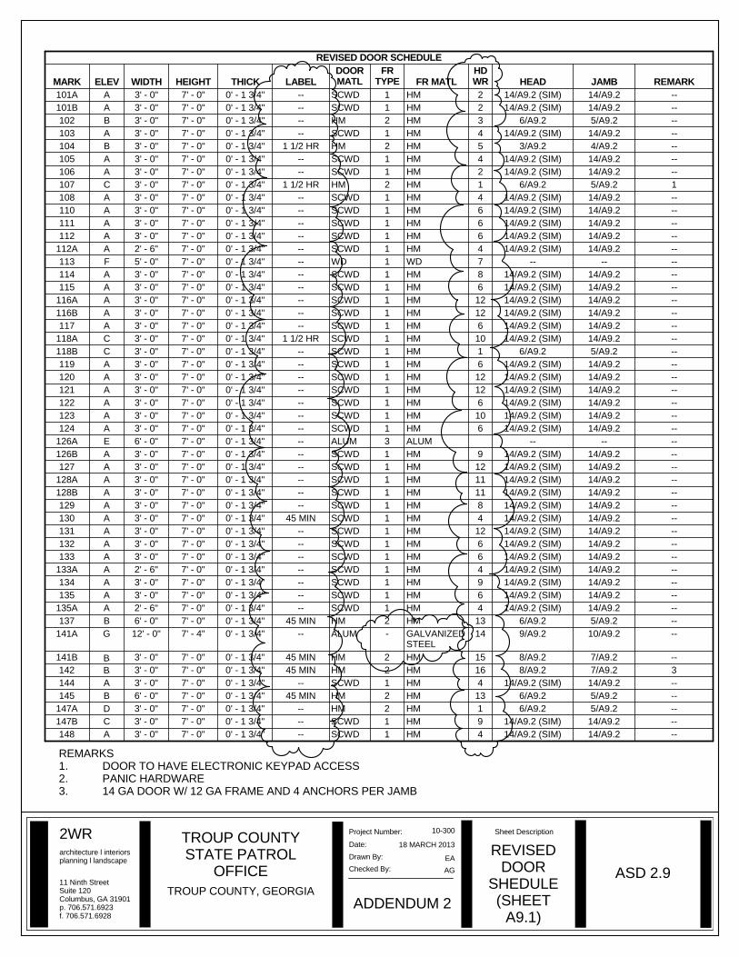
Checked By: ASD 2.9REVISED
DOORSHEDULE(SHEET
A9.1)
TROUP COUNTY, GEORGIA
TROUP COUNTYSTATE PATROL
OFFICEEA
18 MARCH 2013
10-300
ADDENDUM 2
AG
REVISED DOOR SCHEDULE
MARK ELEV WIDTH HEIGHT THICK LABELDOORMATL
FRTYPE FR MATL
HDWR HEAD JAMB REMARK
101A A 3' - 0" 7' - 0" 0' - 1 3/4" -- SCWD 1 HM 2 14/A9.2 (SIM) 14/A9.2 --101B A 3' - 0" 7' - 0" 0' - 1 3/4" -- SCWD 1 HM 2 14/A9.2 (SIM) 14/A9.2 --102 B 3' - 0" 7' - 0" 0' - 1 3/4" -- HM 2 HM 3 6/A9.2 5/A9.2 --103 A 3' - 0" 7' - 0" 0' - 1 3/4" -- SCWD 1 HM 4 14/A9.2 (SIM) 14/A9.2 --104 B 3' - 0" 7' - 0" 0' - 1 3/4" 1 1/2 HR HM 2 HM 5 3/A9.2 4/A9.2 --105 A 3' - 0" 7' - 0" 0' - 1 3/4" -- SCWD 1 HM 4 14/A9.2 (SIM) 14/A9.2 --106 A 3' - 0" 7' - 0" 0' - 1 3/4" -- SCWD 1 HM 2 14/A9.2 (SIM) 14/A9.2 --107 C 3' - 0" 7' - 0" 0' - 1 3/4" 1 1/2 HR HM 2 HM 1 6/A9.2 5/A9.2 1108 A 3' - 0" 7' - 0" 0' - 1 3/4" -- SCWD 1 HM 4 14/A9.2 (SIM) 14/A9.2 --110 A 3' - 0" 7' - 0" 0' - 1 3/4" -- SCWD 1 HM 6 14/A9.2 (SIM) 14/A9.2 --111 A 3' - 0" 7' - 0" 0' - 1 3/4" -- SCWD 1 HM 6 14/A9.2 (SIM) 14/A9.2 --112 A 3' - 0" 7' - 0" 0' - 1 3/4" -- SCWD 1 HM 6 14/A9.2 (SIM) 14/A9.2 --
112A A 2' - 6" 7' - 0" 0' - 1 3/4" -- SCWD 1 HM 4 14/A9.2 (SIM) 14/A9.2 --113 F 5' - 0" 7' - 0" 0' - 1 3/4" -- WD 1 WD 7 -- -- --114 A 3' - 0" 7' - 0" 0' - 1 3/4" -- SCWD 1 HM 8 14/A9.2 (SIM) 14/A9.2 --115 A 3' - 0" 7' - 0" 0' - 1 3/4" -- SCWD 1 HM 6 14/A9.2 (SIM) 14/A9.2 --
116A A 3' - 0" 7' - 0" 0' - 1 3/4" -- SCWD 1 HM 12 14/A9.2 (SIM) 14/A9.2 --116B A 3' - 0" 7' - 0" 0' - 1 3/4" -- SCWD 1 HM 12 14/A9.2 (SIM) 14/A9.2 --117 A 3' - 0" 7' - 0" 0' - 1 3/4" -- SCWD 1 HM 6 14/A9.2 (SIM) 14/A9.2 --
118A C 3' - 0" 7' - 0" 0' - 1 3/4" 1 1/2 HR SCWD 1 HM 10 14/A9.2 (SIM) 14/A9.2 --118B C 3' - 0" 7' - 0" 0' - 1 3/4" -- SCWD 1 HM 1 6/A9.2 5/A9.2 --119 A 3' - 0" 7' - 0" 0' - 1 3/4" -- SCWD 1 HM 6 14/A9.2 (SIM) 14/A9.2 --120 A 3' - 0" 7' - 0" 0' - 1 3/4" -- SCWD 1 HM 12 14/A9.2 (SIM) 14/A9.2 --121 A 3' - 0" 7' - 0" 0' - 1 3/4" -- SCWD 1 HM 12 14/A9.2 (SIM) 14/A9.2 --122 A 3' - 0" 7' - 0" 0' - 1 3/4" -- SCWD 1 HM 6 14/A9.2 (SIM) 14/A9.2 --123 A 3' - 0" 7' - 0" 0' - 1 3/4" -- SCWD 1 HM 10 14/A9.2 (SIM) 14/A9.2 --124 A 3' - 0" 7' - 0" 0' - 1 3/4" -- SCWD 1 HM 6 14/A9.2 (SIM) 14/A9.2 --
126A E 6' - 0" 7' - 0" 0' - 1 3/4" -- ALUM 3 ALUM -- -- --126B A 3' - 0" 7' - 0" 0' - 1 3/4" -- SCWD 1 HM 9 14/A9.2 (SIM) 14/A9.2 --127 A 3' - 0" 7' - 0" 0' - 1 3/4" -- SCWD 1 HM 12 14/A9.2 (SIM) 14/A9.2 --
128A A 3' - 0" 7' - 0" 0' - 1 3/4" -- SCWD 1 HM 11 14/A9.2 (SIM) 14/A9.2 --128B A 3' - 0" 7' - 0" 0' - 1 3/4" -- SCWD 1 HM 11 14/A9.2 (SIM) 14/A9.2 --129 A 3' - 0" 7' - 0" 0' - 1 3/4" -- SCWD 1 HM 8 14/A9.2 (SIM) 14/A9.2 --130 A 3' - 0" 7' - 0" 0' - 1 3/4" 45 MIN SCWD 1 HM 4 14/A9.2 (SIM) 14/A9.2 --131 A 3' - 0" 7' - 0" 0' - 1 3/4" -- SCWD 1 HM 12 14/A9.2 (SIM) 14/A9.2 --132 A 3' - 0" 7' - 0" 0' - 1 3/4" -- SCWD 1 HM 6 14/A9.2 (SIM) 14/A9.2 --133 A 3' - 0" 7' - 0" 0' - 1 3/4" -- SCWD 1 HM 6 14/A9.2 (SIM) 14/A9.2 --
133A A 2' - 6" 7' - 0" 0' - 1 3/4" -- SCWD 1 HM 4 14/A9.2 (SIM) 14/A9.2 --134 A 3' - 0" 7' - 0" 0' - 1 3/4" -- SCWD 1 HM 9 14/A9.2 (SIM) 14/A9.2 --135 A 3' - 0" 7' - 0" 0' - 1 3/4" -- SCWD 1 HM 6 14/A9.2 (SIM) 14/A9.2 --
135A A 2' - 6" 7' - 0" 0' - 1 3/4" -- SCWD 1 HM 4 14/A9.2 (SIM) 14/A9.2 --137 B 6' - 0" 7' - 0" 0' - 1 3/4" 45 MIN HM 2 HM 13 6/A9.2 5/A9.2 --
141A G 12' - 0" 7' - 4" 0' - 1 3/4" -- ALUM - GALVANIZEDSTEEL
14 9/A9.2 10/A9.2 --
141B A 3' - 0" 7' - 0" 0' - 1 3/4" 45 MIN HM 2 HM 15 8/A9.2 7/A9.2 --142 A 3' - 0" 7' - 0" 0' - 1 3/4" 45 MIN HM 2 HM 16 8/A9.2 7/A9.2 3144 A 3' - 0" 7' - 0" 0' - 1 3/4" -- SCWD 1 HM 4 14/A9.2 (SIM) 14/A9.2 --145 B 6' - 0" 7' - 0" 0' - 1 3/4" 45 MIN HM 2 HM 13 6/A9.2 5/A9.2 --
147A C 3' - 0" 7' - 0" 0' - 1 3/4" -- HM 2 HM 1 6/A9.2 5/A9.2 --147B C 3' - 0" 7' - 0" 0' - 1 3/4" -- SCWD 1 HM 9 14/A9.2 (SIM) 14/A9.2 --148 A 3' - 0" 7' - 0" 0' - 1 3/4" -- SCWD 1 HM 4 14/A9.2 (SIM) 14/A9.2 --
REMARKS1. DOOR TO HAVE ELECTRONIC KEYPAD ACCESS2. PANIC HARDWARE3. 14 GA DOOR W/ 12 GA FRAME AND 4 ANCHORS PER JAMB
BB
D