Embed Size (px)
Citation preview

ROBotic Open-architecture Technology forCognition, Understanding and Behavior
Project No. 004370
RobotCubDevelopment of a Cognitive Humanoid Cub
Instrument: Integrated ProjectThematic Priority: IST - Cognitive Systems
D8.2 Definition of Documentationand Manufacturing Procedures
Due date: 1/09/2005Submission Date: 19/09/2005
Start date of project: 01/09/2004 Duration: 60 months
Organisation name of lead contractor for this deliverable: University of Genoa
Responsible Person: F. Becchi, G. Metta, D. Vernon
Revision: 1.0
Project co-funded by the European Commission within the Sixth Framework Programme (2002-2006)Dissemination Level
PU Public PUPP Restricted to other programme participants (including the Commission Service)RE Restricted to a group specified by the consortium (including the Commission Service)CO Confidential, only for members of the consortium (including the Commission Service)

Copyright c©2005 The RobotCub Consortium,European Commission FP6 Project IST-004370.
Permission is granted to copy, distribute and/or modify this document un-der the terms of the GNU Free Documentation License, Version 1.2 or anylater version published by the Free Software Foundation; with no InvariantSections, with Front-Cover Texts being “The RobotCub Project”, and withBack-Cover Texts being “For further information see www.robotcub.org andwww.icub.org”.
A copy of the license is available athttp://www.robotcub.org/icub/license/fdl.txt.

D8.2 Definition of Documentationand Manufacturing Procedures
Contents
I Mechanical and Electronic Design Rules 6
1 Introduction 6
2 Documentation standards and procedures 62.1 Mechanical Documentation Coding Standards . . . . . . . . . . . . . . . . . . . . . 62.2 CAD Documentation Standards . . . . . . . . . . . . . . . . . . . . . . . . . . . . 7
2.2.1 Standard Part . . . . . . . . . . . . . . . . . . . . . . . . . . . . . . . . . . 72.2.2 Standard Assembly . . . . . . . . . . . . . . . . . . . . . . . . . . . . . . . 92.2.3 Drawings — General . . . . . . . . . . . . . . . . . . . . . . . . . . . . . . 92.2.4 Mechanical Drawings Template . . . . . . . . . . . . . . . . . . . . . . . . 102.2.5 Tolerance Classes and Roughness . . . . . . . . . . . . . . . . . . . . . . . 112.2.6 Assembly Drawings Template . . . . . . . . . . . . . . . . . . . . . . . . . 132.2.7 Revision Tables . . . . . . . . . . . . . . . . . . . . . . . . . . . . . . . . . 14
3 Manufacturing Procedures 14
II The iCub CVS Repository 15
4 Getting started with the iCub 15
5 Software structure 165.1 The logpolar module . . . . . . . . . . . . . . . . . . . . . . . . . . . . . . . . . . 18
6 Makefiles 19
7 Compiling on Windows 20
8 A short tutorial 21
9 Compilation support 23
10 Indent utility 23
11 Troubleshooting 23
III Software Documentation and Coding Standards 24
12 Introduction 24
13 Contributing Standards 24
14 Languages, Compilers, and Operating Systems 25
Date: 19/09/2005Version: No 1.0
Page 2

D8.2 Definition of Documentationand Manufacturing Procedures
15 File Names and Naming Conventions 2515.1 Roots of File Names . . . . . . . . . . . . . . . . . . . . . . . . . . . . . . . . . . 2515.2 File Name Extensions . . . . . . . . . . . . . . . . . . . . . . . . . . . . . . . . . 2615.3 Common File Names . . . . . . . . . . . . . . . . . . . . . . . . . . . . . . . . . . 26
16 File Organization 26
17 File Structure 2717.1 General Guidelines . . . . . . . . . . . . . . . . . . . . . . . . . . . . . . . . . . . 2717.2 Structure for C Files . . . . . . . . . . . . . . . . . . . . . . . . . . . . . . . . . . . 27
17.2.1 Declaration of External Functions . . . . . . . . . . . . . . . . . . . . . . . 2717.3 Structure for C++ Files . . . . . . . . . . . . . . . . . . . . . . . . . . . . . . . . . 2817.4 Use of Guards for Header Files . . . . . . . . . . . . . . . . . . . . . . . . . . . . . 28
18 Source Code Documentation 2818.1 Introduction . . . . . . . . . . . . . . . . . . . . . . . . . . . . . . . . . . . . . . . 2818.2 Implementation Comments . . . . . . . . . . . . . . . . . . . . . . . . . . . . . . . 29
18.2.1 Block Comments . . . . . . . . . . . . . . . . . . . . . . . . . . . . . . . . 2918.2.2 Single-Line Comments . . . . . . . . . . . . . . . . . . . . . . . . . . . . . 2918.2.3 Trailing Comments . . . . . . . . . . . . . . . . . . . . . . . . . . . . . . . 2918.2.4 End-Of-Line Comments . . . . . . . . . . . . . . . . . . . . . . . . . . . . 2918.2.5 The First Block Comment . . . . . . . . . . . . . . . . . . . . . . . . . . . 30
18.3 Documentation Comments . . . . . . . . . . . . . . . . . . . . . . . . . . . . . . . 3118.3.1 Preliminaries . . . . . . . . . . . . . . . . . . . . . . . . . . . . . . . . . . 3118.3.2 Brief and Detailed Descriptions . . . . . . . . . . . . . . . . . . . . . . . . 3118.3.3 The First Documentation Comment . . . . . . . . . . . . . . . . . . . . . . 3218.3.4 Documenting Classes . . . . . . . . . . . . . . . . . . . . . . . . . . . . . . 3218.3.5 Putting Documentation after Members . . . . . . . . . . . . . . . . . . . . . 3418.3.6 Documenting Global Code Items . . . . . . . . . . . . . . . . . . . . . . . . 34
19 Programming Style 3519.1 Declarations . . . . . . . . . . . . . . . . . . . . . . . . . . . . . . . . . . . . . . . 35
19.1.1 Number Per Line . . . . . . . . . . . . . . . . . . . . . . . . . . . . . . . . 3519.1.2 Initialization . . . . . . . . . . . . . . . . . . . . . . . . . . . . . . . . . . 35
19.2 Placement . . . . . . . . . . . . . . . . . . . . . . . . . . . . . . . . . . . . . . . . 3619.2.1 Class Declarations . . . . . . . . . . . . . . . . . . . . . . . . . . . . . . . 36
19.3 Statements . . . . . . . . . . . . . . . . . . . . . . . . . . . . . . . . . . . . . . . . 3619.3.1 Simple Statements . . . . . . . . . . . . . . . . . . . . . . . . . . . . . . . 3619.3.2 Compound Statements . . . . . . . . . . . . . . . . . . . . . . . . . . . . . 3619.3.3 return Statements . . . . . . . . . . . . . . . . . . . . . . . . . . . . . . . 3719.3.4 if, if-else, if else-if else Statements . . . . . . . . . . . . . . . . 3719.3.5 for Statements . . . . . . . . . . . . . . . . . . . . . . . . . . . . . . . . 3819.3.6 while Statements . . . . . . . . . . . . . . . . . . . . . . . . . . . . . . . 3819.3.7 do-while Statements . . . . . . . . . . . . . . . . . . . . . . . . . . . . . 3819.3.8 switch Statements . . . . . . . . . . . . . . . . . . . . . . . . . . . . . . 38
19.4 Naming Conventions . . . . . . . . . . . . . . . . . . . . . . . . . . . . . . . . . . 3919.4.1 C vs. C++ . . . . . . . . . . . . . . . . . . . . . . . . . . . . . . . . . . . . 39
Date: 19/09/2005Version: No 1.0
Page 3

D8.2 Definition of Documentationand Manufacturing Procedures
19.4.2 C++ Language Conventions . . . . . . . . . . . . . . . . . . . . . . . . . . 3919.4.3 C Language Conventions . . . . . . . . . . . . . . . . . . . . . . . . . . . . 39
19.5 And Finally: Where To Put The Opening Brace { . . . . . . . . . . . . . . . . . . . 40
20 Programming Practice 4120.1 C++ Language Conventions . . . . . . . . . . . . . . . . . . . . . . . . . . . . . . 41
20.1.1 Access to Data Members . . . . . . . . . . . . . . . . . . . . . . . . . . . . 4120.2 C Language Conventions . . . . . . . . . . . . . . . . . . . . . . . . . . . . . . . . 4120.3 General Issues . . . . . . . . . . . . . . . . . . . . . . . . . . . . . . . . . . . . . . 41
20.3.1 Conditional Compilation . . . . . . . . . . . . . . . . . . . . . . . . . . . . 4120.3.2 Writing Robust Programs . . . . . . . . . . . . . . . . . . . . . . . . . . . 4220.3.3 Constants . . . . . . . . . . . . . . . . . . . . . . . . . . . . . . . . . . . . 4220.3.4 Variable Assignments . . . . . . . . . . . . . . . . . . . . . . . . . . . . . 4220.3.5 Parentheses . . . . . . . . . . . . . . . . . . . . . . . . . . . . . . . . . . . 4320.3.6 Standards for Graphical Interfaces . . . . . . . . . . . . . . . . . . . . . . . 4320.3.7 Error Messages . . . . . . . . . . . . . . . . . . . . . . . . . . . . . . . . . 4320.3.8 License Messages . . . . . . . . . . . . . . . . . . . . . . . . . . . . . . . . 43
Date: 19/09/2005Version: No 1.0
Page 4

D8.2 Definition of Documentationand Manufacturing Procedures
Overview
Deliverable D8.2 sets out the procedures by which the iCub is to be manufactured and documented,addressing both the hardware mechatronic components and the software systems. It comprises threemajor parts: the first deals with the procedures for manufacturing and documenting the iCub mecha-tronic platform, the second comprises a set of guidelines on downloading and uploading iCub softwarefrom and to the CVS repository, and the third provides a set of guidelines for software documentation,programming style, and programming practice. The third part also provides guidance on how to nameand structure files to be included in the iCub software repository. The intention is that these guidelinesshould be short enough to be easily adopted and applied, but long enough to be useful in the creationof high-quality easily-maintained software.
Date: 19/09/2005Version: No 1.0
Page 5

D8.2 Definition of Documentationand Manufacturing Procedures
Part I
Mechanical and Electronic Design Rules1 Introduction
The basis for collaboration between the different groups involved in the design of the iCub platformis the definition of common rules and tools for the design itself. From the very beginning severalinstances were fixed in order to maximize the information interchange between the partners and theintegration of all the contributions in a single final design. In this part, the standards for the mechan-ical documentation are set out. Detailed CAD standards are defined, some of which are platform-dependent. A brief survey of the different manufacturing technologies and procedures adopted for therealization of the first prototypes of the iCub is also included.
2 Documentation standards and procedures
The RobotCub consortium has chosen PTC/Pro ENGINEER Wildfire 2.0 as the CAD software pack-age for all official iCub design work. This choice of commercial sofware was necessary as no opensoftware package capable of dealing with a system of the complexity of iCub was available.
2.1 Mechanical Documentation Coding Standards
This section explains the coding standards agreed for the mechanical documentation. All the de-sign development done in the RobotCub project must adhere to these standards to ensure completetraceability of the file. The same coding is also recommended as an internal standard for each groupinvolved in the iCub mechanical platform documentation.
The coding procedure gives an alphanumeric filename code to each file produced in the design processfrom part files to assembly drawings. The same coding should also be used for the written documen-tation (e.g. calculation report).
The fields in the code are:
RC common to all Robotcub Consortium documentation.
GROUP: this denotes the acronym of the group to which the author belongs. Currently definedacronyms are listed below:
UGDIST SSSA
UNIZH UNIUP
UNIFE UNIHER
IST UNISAL
EPFL TLR
EBRI
Date: 19/09/2005Version: No 1.0
Page 6
D8.2 Definition of Documentationand Manufacturing Procedures
VERSION: this is a numeric field unique for each different design or solution. This is the main assem-bly code: it allows for different designs of the same assembly. For example, there might be severaldifferent (i.e. alternative) shoulder assemblies and each design will have its own unique version num-ber.
LETTER: The letter is a type identifier which signifies what the file contains, as follows.
A Top Assembly (the top assembly is the higher assembly in the model tree)G Group (a group is a lower level assembly in the model tree)P PartD Documentation file (e.g. doc or xls filesLY 2D layout file (e.g. preliminary 2D design on Autocad)
CODE: This is the identification code in the current project (each part or group has its own identifica-tion code).
RELEASE: this is the release number of the file (this code must match the REVISION in the drawing;see later).
DESCRIPTION: this is an extra field that can be used for better file identification (e.g. left eye pulley).
Following this standard for naming files, the first part of the first design made by Telerobot would be:
RC_TLR_001_P_001_00_FIRST_PART
Note: No spaces are to be included in the filename. Use the underscore “_” to separate words ifnecessary.
2.2 CAD Documentation Standards
A set of rules for the correct definition of each file of a 3D CAD Pro/ENGINEER model is presentedin this section. Standard ROBOTCUB part (*.prt) and standard ROBOTCUB assembly (*.asm) aredefined. The drawing template and consequent parameters is also discussed.
2.2.1 Standard Part
The standard part for RobotCub project is named “PART_RC_2001.prt”. This part must be used forcreating new ones (using the “Save as . . .” or the “New” file options commands). For common ref-erence, the standard part is the same for all the consortium and must not be modified. The parametersdefined in each part file are listed below.
Date: 19/09/2005Version: No 1.0
Page 7

D8.2 Definition of Documentationand Manufacturing Procedures
DESCRIPTION Description of the partSUBDESCRIPTION Optional sub-description for the part (i.e. the group in which this part will be assembled, . . .)DESIGNED The group acronym (see above)DRAWN The name of the group designerREV Revision of the part (numeric: 1, 2, 3, . . ..)TREATMENT The treatment that will be applied to the partMATERIAL The material assigned to the part. This parameter is filled in using
the Pro/E command “Setup – Material– Assign – From Part”.
The parameters highlighted in green are filled by the user.
The materials that can be used are already reported in the standard part. The list is defined fromprevious similar design experience. The list can be enlarged if required. This procedure is necessaryin order to assign the right density to the part (and consequently the right mass). The default materialassigned to the standard part is Al6082. The right one must be assigned. The materials added to thestandard part are as follows.
17-4PH Al6082
Armonic steel Brass
Carbon fiber Delrin
Ergal70 Lexan
Neoprene Orkot
PE PEEK
Plexiglass PP
PTFE PVC
Rynite 555 AISI 316
AISI 420
The parameters highlighted in red:
Date: 19/09/2005Version: No 1.0
Page 8

D8.2 Definition of Documentationand Manufacturing Procedures
MASS
VOLUME
DENOMINAZIONE
TIPO
are filled by the system at the first regeneration of the part. MASS is directly dependent for theMATERIAL parameter (using the density value reported in the material file).
2.2.2 Standard Assembly
The standard assembly for the RobotCub project is named “ASSY_RC_2001.asm”. This file must beused when creating a new assembly (using the “Save as . . .” or the “New” file options commands).
In the same way as the standard part, for consistency the standard assembly is the same for all theconsortium and must not be modified. The parameters defined in each assembly file are listed below.
As described before, the parameter highlighted in green are defined by the user. The red ones aredefined by the system at the first regeneration. Note: the MASS parameter is automatically calculatedby the system as a sum of all the parts mounted in assembly in every regeneration of the model.
2.2.3 Drawings — General
The standard sheet drawing format are:
Robot_cub_a0_mech A0 format for mechanical drawingsRobot_cub_a0_ass A0 format for assembly drawingsRobot_cub_a1_mech A1 format for mechanical drawingsRobot_cub_a1_ass A1 format for assembly drawingsRobot_cub_a2_mech A2 format for mechanical drawingsRobot_cub_a2_ass A2 format for assembly drawingsRobot_cub_a3_mech A3 format for mechanical drawingsRobot_cub_a3_ass A3 format for assembly drawingsRobot_cub_a4_mech A4 format for mechanical drawingsRobot_cub_a4_ass A4 format for assembly drawings
Date: 19/09/2005Version: No 1.0
Page 9

D8.2 Definition of Documentationand Manufacturing Procedures
2.2.4 Mechanical Drawings Template
The main table included in the mechanical drawings is described below.
The values highlighted in red are automatically filled in by the system:
MATERIAL The material assigned to the part (see above)DWG_NAME The name of the drawing file; this must be the same as the reference 3D modelSCALE Scale value of the drawingSHEET Sheet number (i.e. for two sheets of the same drawing: 1/2, 2/2, . . ..)DATE Drawing creation dateMASS Mass value (part parameter, see above)
The values highlighted in green have are defined by the user if not already filled in the reference part:
TREATMENT Treatment assigned to the part (if completed in the part,the value will be reported in the table automatically)
UNDIM. ROUNDS Undimensioned rounds in the partUNDIM CHAMFERS Undimensioned chamfers in the partISSUED The company abbreviation in RobotCub
(i.e. for Telerobot is TLR) (already completed in the part)DRAWN The name of the group designerCHECKED The name of the group checkerAPPROVED The name of the group designerREV. Revision of the document (part parameter, see above)DIMENSIONAL TOLERANCE CLASS Dimensional tolerance class; see below for more detailsGEOMETRIC TOLERANCE CLASS Geometric tolerance class; see below for more detailsROUGHNESS Part roughness; see below for more detailsASSEMBLY REF. Assembly in which the part is mounted (assembly code);
the parameter name is “mounted on asm”DESCRIPTION Description and eventually sub-description of the part
(already completed in the part)
Date: 19/09/2005Version: No 1.0
Page 10

D8.2 Definition of Documentationand Manufacturing Procedures
When the user inserts a format in the drawing, the system automatically requires the TYPE of all theparameter which aren’t in the reference part (that is to say: UNDIM. ROUNDS, UNDIM CHAMFERS,CHECKED, APPROVED, REV., MOUNTED_ON_ASM, TOL_DIM_CLASS, TL_GEOM_CLASS). For all theparameters, the type is “STRING”. After the type definition, the user has to fill the parameter valuefor every parameter requested. Note: parameters can be easily modified with the “Edit - Value”command.
2.2.5 Tolerance Classes and Roughness
For Dimensional tolerance class parameter, the following values have to be used:
f
m
c
v
Note: these values have to be written in lower case.
For Geometric tolerance class parameter, the values that have to be used are the following, accordingto the table below reported:
H
K
L
Note: these values have to be written in upper case.
Date: 19/09/2005Version: No 1.0
Page 11
D8.2 Definition of Documentationand Manufacturing Procedures
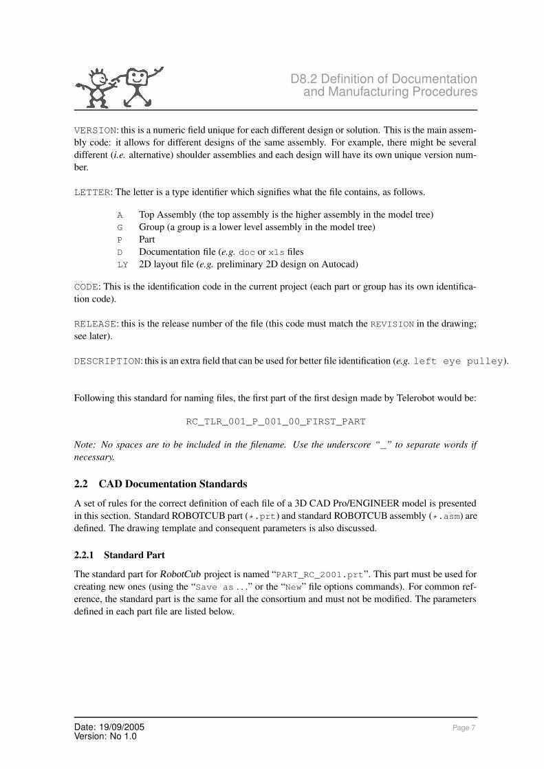
The roughness reported in the drawing format is a symbol chosen from the options below.
General
Only No Removal
No Removal, with 1 other machined roughness
No Removal, with 2 other machined roughnesses
Machined
Machined, with 1 other machined roughness
Machined, with 2 other machined roughnesses
In all cases the symbol must be completed before its insertion with the “Var text” value. Forroughness symbol in the drawing, the Pro/ENGINEER standard symbol (“isosurftext.sym”) inthe “System Sym” directory should be used.
Date: 19/09/2005Version: No 1.0
Page 12
D8.2 Definition of Documentationand Manufacturing Procedures
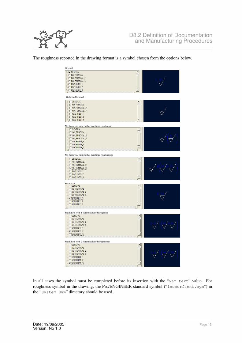
2.2.6 Assembly Drawings Template
The main table reported in assembly drawing formats is described here.
It is similar to the mechanical drawing table, without the last 4 rows. The same instructions apply.
In case of an assembly drawing, it might be necessary the insert a BOM (Bill Of Material) table.The “BOM_table” file can be used. This table will be automatically filled by the system, readinginformation reported in parts (or sub-assemblies) parameters.
The “with qty” BOM balloon type can be used. An image of a BOM ballooned assembly is shown below.
Date: 19/09/2005Version: No 1.0
Page 13

D8.2 Definition of Documentationand Manufacturing Procedures
2.2.7 Revision Tables
In the case of a document revision, the rules below described will apply.
Insert the new revision table (in the upper part of the drawing for A4, the upper-right for the otherformats; see diagram below).
Rev1_table for the first revision on the documentRev2_table for the second revision on the documentRev3_table for the third revision on the document
The required parameters are as follows (always STRING type).
Reviewer the group that creates the document revisionDescription revision descriptionZone the zone in the drawing where this revision is visibleDate the revision dateDrawn who draws the revisionChecked who checks the revisioned document
The same instructions must be followed in case of a second or third revision (the table with theprevious revision has to be deleted).
3 Manufacturing Procedures
In the design of the iCub mechanical components, several different technologies were discussed andanalyzed. To date, the prototypes have have typically been realized using:
• Aluminium alloys/steel machining (with traditional CNC mill, lathe, laser cut, spark erosionand wire cut);
• Rapid prototyping for preliminary design evaluation or as starting point for other manufacturingtechnology (as for external cover made with glass or carbon fiber starting from a RP model).
The experience of each group has been shared by all the consortium in the definition of best designapproach. No defined procedures have yet been agreed. Once the first complete prototype has beenintegrated and tested, industrial drawing and manufacturing, assembly, and integration procedures willbe defined.
Date: 19/09/2005Version: No 1.0
Page 14

D8.2 Definition of Documentationand Manufacturing Procedures
Part II
The iCub CVS Repository4 Getting started with the iCub
The iCub software is maintained by means of CVS. The CVS repository can be accessed at:“cvs.robotcub.org” or browsed on the web at: “http://www.robotcub.org/iCub”.The access to the repository is only by secure shell (ssh). Before accessing the repository you needto ask the maintainer (LIRA-Lab at the moment of writing) to create an account for you and set yourpassword. The ssh access allows full control of the repository (add, checkout, commit).The repository access has been tested also from the popular WinCVS client. It delivers reasonableperformances. If you’re not keen on GUIs you can still use cvs from the command line both on Linuxand Windows systems.The same code can be accessed also from SourceForge. We have a project called “robotcub” hostedin SourceForge. The project group page is at:
http://sf.net/projects/robotcub
while the home page:
http://robotcub.sf.net
redirects you to the standard RobotCub.org website.Once you receive the account name and password you can log in with any ssh client and use “passwd”to change your password to something you like. You should also start setting up your environmentto download the code to your local machine. CVS, in short, works by creating a local copy of therepository on your local hard drive that you can use to modify and compile the code. Changes canlater be uploaded back to the common repository through the “commit” command.The remote repository location and connection method is specified by an environment variable calledCVSROOT. The following two lines:
export CVSROOT=:ext:[email protected]:/cvsroot/robotcubexport CVS RSH=/usr/bin/ssh
would set the CVSROOT to use ssh and connect to cvs.robotcub.org with username “YOURNAME”and sets the root to “/cvsroot/robotcub”. Note that these are exactly the pathnames you shoulduse to connect to the iCub repository. On Linux, you can simply change to the directory you intend touse for your local copy of the repository and type:
$ cvs co -P iCub
which checks the “iCub” module out and prune (-P) the empty directories in the repository (does notcheck out the empty directories). On Windows you should setup things a bit differently. A tutorial onthe CVS client configuration is available for example from:
http://sourceforge.net/docman/display doc.php?docid=25888&group id=1
You can also use the cvsnt package from the command line, e.g:
Date: 19/09/2005Version: No 1.0
Page 15

D8.2 Definition of Documentationand Manufacturing Procedures
D:\Users\pasa\Repository\prova>cvs -d:ssh;username=pasa;hostname=cvs.robotcub.org:/cvsroot/robotcub co iCubPassword:Response: **********cvs checkout: cwd=D:\Users\pasa\Repository\iCub ,current=D:\Users\pasa\Repository\iCubcvs server: Updating iCubU iCub/AUTHORSU iCub/COPYINGU iCub/INSTALLU iCub/READMEU iCub/TODOcvs server: Updating iCub/binU iCub/bin/dummy.txt
and so forth. The command above asks for a checkout (co), uses ssh for authentication with unsernameset to pasa and hostname cvs.robotcub.org and root directory /cvsroot/robotcub. Finally, it asks forthe module iCub which is the only available module at the moment of writing.The basic commands available to CVS for manipulating the repository are:
• add: to add files and directories to the repository
• update: to get an up-to-date version of the code from the repository
• checkout: to get the first-time copy (or a new one) of the repository
• commit: to upload changes to any file into the repository
Please consult the CVS manual (or help) for more information about using CVS. It is worth notingthat CVS does not allow removing or renaming directories, thus extreme care should be taken whencreating new directories. The administrator can move or rename directories but it has to be donemanually and it can risk the integrity of the repository (depending on the administrator of course).CVS was chosen for its stability. It is an “old” application which is now fairly stable and well tested.SourceForge uses CVS and, although there are new versioning applications being developed, theyare not yet as stable as CVS. These were the reasons for choosing CVS for serving our softwarerepository. The simpler the better.Finally, CVS allows concurrent development of code by merging changes to files. This mechanismhas to be used parsimoniously but it works well in general. Versions are maintained of every file sothat older versions can be recovered at any time. In the following, the forward slash / is always usedeven to indicate Windows paths; depending on the shell/terminal you use you might need to replacethe forward with the backslash.
5 Software structure
The software directory tree was chosen to be modular and extensible. The idea is to live with manyseparate modules perhaps developed by different people that glued together will make the iCub tofunction. Although CVS allows the creation of various independent modules they cannot be organizedhierarchically, which makes things a bit more difficult. It has been chosen then to define modulessimply by the placing them in different directories without relying on the CVS module mechanism.The main module of our repository is called “iCub” which is also the root directory on the repository.
Date: 19/09/2005Version: No 1.0
Page 16
D8.2 Definition of Documentationand Manufacturing Procedures
When checking out the code you’re are requested to give a module name. This is exactly “iCub”.The capitalized “C” is mandatory.The following table summarizes the directory organization:
Directory name Descriptionconf configuration and template filesdoc documentation and manuals
license license files and templatessrc the source code
The “src” directory is the main container of the source code. It contains various subdirectories whichcontain in turn independent modules (logically distinct pieces of software). Each subdirectory can beorganized freely by the developers as long as it compiles properly with the rest of the system. Inorganizing the code development, Makefile’s are provided and rules given in a tentative to harmonizethe final result.The filenames should be consistent with the RobotCub standards in:
RC DIST DV standards filename convention.pdf
that can be found in the “license” directory. The iCub header files, once intalled, should be even-tually contained all into a common directory. It is perhaps best to avoid mingling with the standardsystem header files. For this reason header files are included always from a subdirectory called (sur-prise surprise!) “iCub” of any include directory. An example of inclusion in C or C++ would besomething like this:
#include <iCub/RC_DIST_GM_cognition_module.h>
Thus, you should organize your header files in something like “include/iCub” and provide a pathto the compiler of the form “include”. Installation can copy these files somewhere, as for example,into “/usr/local/include/iCub”. Makefile’s are provided which would take care of installingthings properly (if used). Standard templates can be found in “conf”. An example of a module is the“logpolar” described next.We distinguish three types of compilation and/or installation that perform different operations:
• local: used when developing on the current module;
• install: used when developing across many modules;
• system install: used to install the iCub code for general use on a given machine.
Thus when developing a specific module, the user does not have to disturb the rest of the system,unless there are dependencies with other subparts. As a consequence a local compilation would do. Itis likely though that dependencies would develop across modules. It would then be unconvenient tohave to link explicitly and provide paths for every possible module being used. In this case a partialinstall is useful by copying libraries and header files into a common iCub-wide directory. As a lastoption, when the system is ready to be deployed a possibly used by many users (perhaps connected tothe same hardware platform) a system install is required. This typically copies the library, executables,and header files in some common place (e.g. /usr/local on Linux).Our code is going to be multi-platform. We have decided to support Windows, Linux, and MacOS.The controller of the iCub is likely to run on multiple machines in parallel; consequently several
Date: 19/09/2005Version: No 1.0
Page 17
D8.2 Definition of Documentationand Manufacturing Procedures
compilation might reside on the same directory tree. This is accomplished by defining a subdirectoryfor each compilation: i.e. libraries will be stored in places like “lib/linux” or “lib/winnt”.The same applies to binaries.The valid directory names for the various OSs are:
• winnt
• linux
• darwin
We need then to revise our previous table by adding a few directories to allow the install (not thesystem install!) on the current copy of the repository. It is useful to have an environment variablepointing to this root directory (the same place where we’ve done the checkout). We have chosen touse ICUB ROOT which can be set for example by the following command:
export ICUB ROOT=/usr/src/iCub
which throughout this manual will be referred as “$ICUB ROOT”. Also, in case you are planning thesystem-wide install another environment variable should be defined. This is ICUB INSTALL whichcan be defined for example by the following command:
export ICUB INSTALL=/usr/local/iCub
which will be also referred as “$ICUB INSTALL”.Consequently, we need also the following directories for the local install under the $ICUB ROOTdirectory:
Directory name Descriptioninclude/iCub header files
lib with subdirectories for different OSsbin executables, with subdirectories for different OSs
Section 6 describes these different istallation and compilation options in details.
5.1 The logpolar module
We preferred to explain the organization of the code by providing an example of a self containedstatic library that converts images back and forth from rectangular to logpolar. The logpolar mappingis a model of the distribution of photoreceptors in the human retina. For a detailed manual of thismodule, please, check the documentation provided with the module (Doxygen & LaTeX). The tablenext shows the organization within the directory called “logpolar”:
Directory name Descriptionsrc source code and makefile’sdoc documentation and manuals
include/iCub header filestools application code
the home directory contains also the Doxygen file for building the reference manual and the mainMakefile. Compilation would happen locally (see Makefile) and the results would be stored in “obj/”within a subdirectory specific to your operating system. This module builds a static library called:
Date: 19/09/2005Version: No 1.0
Page 18

D8.2 Definition of Documentationand Manufacturing Procedures
lib iCub logpolar.*
where the * stands for the library extension on your system (e.g. .lib). On a local compilation (distinctfrom the system install) libraries are copied into a lib directory (in this case “logpolar/lib/”)under a directory specific to your operating system (e.g. linux).For more information please have a look at the “doc” directory and at the Doxygen manual pages.Also, the “logp libtest” under “tools” contains an example that loads a rectangular image andperforms the logpolar sampling and back to rectangular (remapping) performing the color reconstruc-tion simultaneously. In addition, since several digital cameras have a Bayer pattern output, instead ofthe more traditional RGB, functions to reconstruct the RGB color from the Bayer battern have beenimplemented directly in the library.
6 Makefiles
In the example, several Makefile templates have been introduced. While it is not mandatory to usethem, they are provided in the repository to ease the smooth integration of different modules. AllMakefile’s allow the following commands:
• clean: to clean the previous compilation object files;
• default: to build the current directory, possibly recursively; if you just type “make” it woulddo;
• install: to install locally, which means starting from “$ICUB ROOT”;
• sysinstall: to install system-wide to the local machine, which means copying files into“$ICUB INSTALL”;
We have already mentioned the role of the different install options. In particular by typing “make”,compilation would start and the libraries and executables will be stored in a subdirectory of the cur-rent module (./lib and ./bin respectively). The templates are found in $ICUB ROOT/conf. They aretypically included in the main makefile’s rather than used directly. In particular:
• Makefile.def: this template contains some definitions that are useful for compiling under thedifferent OSes. For example, it tests the shell and sets the value of the $OS variable;
• Makefile.plain.template: this file can be included and used to compile recursively without anyinstall. It simply checks a list of directories for additional makefile’s and runs them;
• Makefile.src.template: this makefile can be included to compile static libraries following theiCub format presented in this document. It also contains the instructions for installing eitherlocally or system-wide;
• Makefile.recursive.template: this is another makefile similar to the plain one for recursive com-pilation. It is different from the plain one in that it installs also from the current module direc-tory;
• Makefile.tool.template: this makefile can be included to provide the instructions for compilingan executable and install it appropriately.
Date: 19/09/2005Version: No 1.0
Page 19

D8.2 Definition of Documentationand Manufacturing Procedures
Option name DescriptionCFAST = -g compile with debug on, default offMYLIB = ... add a list of libraries to be linked
All makefile’s accept the following compilation options:For example:
$ make CFAST=-g
would compile with the debugging information into the generated code.
7 Compiling on Windows
Compilation on Windows is performed through the Microsoft Visual Studio 6.0. There are twoprojects to be used for compiling the library first and then the example as shown below for Linux.The project contains both the configurations for compiling locally (no install) or to perform the instal-lation on the $ICUB ROOT directory. The configuration for installing globally is not implementedyet.As an example, starting the “build” command would display something like this on the outputwindow:
-------Configuration: RC_LogPolar - Win32 Release Install--------Compiling...RC_DIST_FB_logpolar_mapper.cppCreating library...Installing.....\include\iCub\RC_DIST_FB_logpolar_mapper.h
1 file(s) copied...\lib\winnt\lib_iCub_logpolar.lib
1 file(s) copied.
lib_iCub_logpolar.lib - 0 error(s), 0 warning(s)
On Windows, there are always two different libraries generated whether the debug option is on. Theversion with the debug “on” has a trailing lowercase “d” in the filename. The extension is “lib” whichis standard in Windows. Libraries are better static (not DLL) since remoting would be easier: i.e. incase the applications have to be run on a remote machine only the executables has to be physicallymoved there.A similar project exists for compiling the test applications: have a look into the “tools” directoryfor a VisualStudio workspace (.dsw). Also in this case, there is the option to perform the installation.The syntax for executing the test application is exactly the same as in Linux (see below in section 8).As for Linux, you should take care of setting the proper path for running the application directly fromthe command window.
Date: 19/09/2005Version: No 1.0
Page 20
D8.2 Definition of Documentationand Manufacturing Procedures
8 A short tutorial
Compiling the logpolar example is fairly straightforward provided the environment is set as men-tioned above. In particular, once more, make sure you have defined the $ICUB ROOT environmentvariable. This is required by the makefile provided. It would be convenient to add the directory ofthe binaries to the PATH environment variable (e.g. $ICUB ROOT/-bin/linux) so that you can run theiCub applications just by typing their names at the command line. To start, then, just type:
$ cd $ICUB ROOT
which brings you to the iCub software directory. If you “ls” there you should see something likethis:
drwxr-xr-x 10 pasa users 4096 2005-07-08 01:48 .drwxr-xr-x 8 root root 4096 2005-07-09 01:24 ..-rw-r--r-- 1 pasa users 70 2005-05-26 12:35 AUTHORSdrwxr-xr-x 6 pasa users 4096 2005-07-08 01:48 bindrwxr-xr-x 3 pasa users 4096 2005-07-09 02:15 conf-rw-r--r-- 1 pasa users 313 2005-05-26 12:35 COPYINGdrwxr-xr-x 2 pasa users 4096 2005-07-08 01:48 CVSdrwxr-xr-x 4 pasa users 4096 2005-07-08 01:48 docdrwxr-xr-x 4 pasa users 4096 2005-07-08 01:48 include-rw-r--r-- 1 pasa users 50 2005-05-26 12:35 INSTALLdrwxr-xr-x 6 pasa users 4096 2005-07-08 01:48 libdrwxr-xr-x 3 pasa users 4096 2005-07-08 01:48 license-rw-r--r-- 1 pasa users 93 2005-05-26 12:35 READMEdrwxr-xr-x 4 pasa users 4096 2005-07-08 14:11 src-rw-r--r-- 1 pasa users 16 2005-05-26 12:35 TODO
which should resemble the directory structure we described earlier. To start compilation then justtype:
$ cd src/logpolar$ make
Your terminal should display something like this:
make[1]: Entering directory ‘/usr/src/iCub/src/logpolar/src’mkdir -p ../obj/linuxg++ -D_REENTRANT -O3 -I../include -I/usr/src/iCub/include/linux-fexceptions -pipe -Wpointer-arith -Wno-uninitialized -D__LINUX__-DICUB_OS_CONFIG=LINUX -I/usr/include/g++/ -I/usr/src/iCub/include/-DACE_NDEBUG -DACE_USE_RCSID=0 -DACE_HAS_EXCEPTIONS -D__ACE_INLINE__-DACE_HAS_ACE_TOKEN -DACE_HAS_ACE_SVCCONF -DACE_AS_STATIC_LIBS-c RC_DIST_FB_logpolar_mapper.cpp -o../obj/linux/RC_DIST_FB_logpolar_mapper.omkdir -p ../lib/linuxMaking lib_iCub_logpolar.a for ../obj/linux/RC_DIST_FB_logpolar_mapper.o
Date: 19/09/2005Version: No 1.0
Page 21

D8.2 Definition of Documentationand Manufacturing Procedures
ar rv ../lib/linux/lib_iCub_logpolar.a../obj/linux/RC_DIST_FB_logpolar_mapper.oar: creating ../lib/linux/lib_iCub_logpolar.aa - ../obj/linux/RC_DIST_FB_logpolar_mapper.omake[1]: Leaving directory ‘/usr/src/iCub/src/logpolar/src’make[1]: Entering directory ‘/usr/src/iCub/src/logpolar/tools’make[2]: Entering directory ‘/usr/src/iCub/src/logpolar/tools/logp_libtest’mkdir -p obj/linuxg++ -O3 -I/usr/src/iCub/include/linux -I/usr/src/iCub/include -I.-fexceptions -pipe-Wpointer-arith -Wno-uninitialized -D__LINUX__ -DICUB_OS_CONFIG=LINUX-I/usr/include/g++/ -I/usr/src/iCub/include/ -DACE_NDEBUG -DACE_USE_RCSID=0-DACE_HAS_EXCEPTIONS -D__ACE_INLINE__ -DACE_HAS_ACE_TOKEN-DACE_HAS_ACE_SVCCONF -DACE_AS_STATIC_LIBS -c RC_DIST_FB_logp_test.cpp-o obj/linux/RC_DIST_FB_logp_test.omkdir -p ../bin/linuxg++ -O3 -I/usr/src/iCub/include/linux -I/usr/src/iCub/include -I.-fexceptions -pipe-Wpointer-arith -Wno-uninitialized -D__LINUX__ -DICUB_OS_CONFIG=LINUX-I/usr/include/g++/ -I/usr/src/iCub/include/ -DACE_NDEBUG -DACE_USE_RCSID=0-DACE_HAS_EXCEPTIONS -D__ACE_INLINE__ -DACE_HAS_ACE_TOKEN-DACE_HAS_ACE_SVCCONF -DACE_AS_STATIC_LIBS obj/linux/RC_DIST_FB_logp_test.o-o ../bin/linux/logp_libtest-L/usr/src/iCub/lib/linux ../../lib/linux/lib_iCub_logpolar.a -lpthread -ldlmake[2]: Leaving directory ‘/usr/src/iCub/src/logpolar/tools/logp_libtest’make[1]: Leaving directory ‘/usr/src/iCub/src/logpolar/tools’
where you should recognize the compilation of the static library and subsequently of the library testapplication. You might want then to install them locally by typing:
$ make install
with the following result:
Installing lib_iCub_logpolar.a to /usr/src/iCub/lib/linuxmkdir -p /usr/src/iCub/include/iCubInstalling RC_DIST_FB_logpolar_mapper.h to /usr/src/iCub/include/iCubmake[1]: Entering directory ‘/usr/src/iCub/src/logpolar/src’mkdir -p /usr/src/iCub/lib/linuxmkdir -p /usr/src/iCub/include/iCubcp ../lib/linux/lib_iCub_logpolar.a /usr/src/iCub/lib/linuxcp -f ../include/iCub/*.h /usr/src/iCub/include/iCubmake[1]: Leaving directory ‘/usr/src/iCub/src/logpolar/src’make[1]: Entering directory ‘/usr/src/iCub/src/logpolar/tools’make[2]: Entering directory ‘/usr/src/iCub/src/logpolar/tools/logp_libtest’mkdir -p /usr/src/iCub/bin/linuxcp ../bin/linux/logp_libtest /usr/src/iCub/bin/linuxmake[2]: Leaving directory ‘/usr/src/iCub/src/logpolar/tools/logp_libtest’make[1]: Leaving directory ‘/usr/src/iCub/src/logpolar/tools’
which finally copies everything to the right place. For example the executable is copied into\$ICUB\_ROOT/bin/linux in this case. To test the application, change directory to./tools/logp\_libtest and run:
Date: 19/09/2005Version: No 1.0
Page 22

D8.2 Definition of Documentationand Manufacturing Procedures
$ logp libtest imagebayer.bmp
which runs for a while generating several examples of logpolar and remapped images. In an idealworld you should get the following response:
logp_libtest: loading bitmaplogp_libtest: reconstructing color from bayer patternlogp_libtest: building a logpolar image, bayer pattern, no color reconstructionlogp_libtest: reconstructing logpolar colorlogp_libtest: building color logpolar imagelogp_libtest: remapping from logpolar to rectangular
Note that this example is not supposed to run in realtime since it builds the conversion tables on thefly, while in the general case they can be built once and reused. In the same directory you will seeseveral test images of the logpolar conversion for you to see.
9 Compilation support
The iCub servers will provide one machine per OS with ssh access to test compilation in a stan-dard environment (Linux, Windows, MacOS). At the moment of writing we have a linux box athydra.lira.dist.unige.it for this purpose. When this type of support will be fully available we willadvertize it appropriately.
10 Indent utility
You can use “indent” to properly indent your code. The following command seems to work wellwith respect to the specifications of the iCub code:
$ indent FILENAME -bli0 -ts4 -nut -i4
It is not perhaps fully compliant yet.
11 Troubleshooting
Please contact Giorgio Metta at [email protected] had you to encounter any problem, diffi-culty or a plain bug in either this manual or the CVS repository. The logpolar code was developed byFabio Berton ([email protected]) and he is the one to blame (don’t!).
Date: 19/09/2005Version: No 1.0
Page 23
D8.2 Definition of Documentationand Manufacturing Procedures
Part III
Software Documentation and Coding Standards12 Introduction
RobotCub is a collaborative project, both in its current developmental phase, when members of theconsortium are working together to create this cognitive humanoid cub, and in its subsequent evolu-tionary phase, when the rest of the cognitive systems scientific community will join in the on-goingenhancement of the iCub. Our goal is to create a system that can be easily adopted and modifiedby others. This in turn requires that it is presented as a consistent integrated body of work. Codingand documentation standards help us achieve this goal (although they are by no means sufficient toachieve the goal).
Ideally, all software is complemented both by informative in-line source code comments and by help-ful external documents (such as tutorials, user manuals, and reference manuals). In the RobotCubproject, we strongly encourage contributors to provide this type of external documentation, but it isnot mandatory. Instead, we depend on well-documented in-line source code. We use the Doxygen tool[6] to extract source code comments and automatically create supporting documentation. The sourcecode comments that are used by Doxygen must be identified by certain markup conventions and inthe following we will distinguish between comments that are intended for automatic extraction anddocument creation by Doxygen and those that are intended only to enhance and explain the sourcecode. However, we will provide guidelines for both types of comments. In addition, we will alsoprovide a guide for formatting source code and a set of guidelines for programming style. We alsoprovide a set of guidelines for naming conventions, including file-names.
In summary then, this deliverable provides a set of standards for:
1. Source code documentation (for extraction and document generation by Doxygen)
2. Source code comments (for explaining and illuminating the source code)
3. Formatting source code
4. Programming style
5. File name conventions
Because iCub software is written in a mix of conventional (imperative) C and object-oriented C++, wewill to distinguish where appropriate between standards that apply to C source code, to C++ sourcecode, and to both.
13 Contributing Standards
In creating these standards, we have drawn from several sources. These include:
• GNU Coding Standards [5];
• Java Code Conventions[4];
Date: 19/09/2005Version: No 1.0
Page 24

D8.2 Definition of Documentationand Manufacturing Procedures
• C++ Coding Standard[2];
• The EPFL BIRG Coding Standards[1];
• The Doxygen User Manual[6].
The standards set out in this document represent an attempt to find a balance between specifying toomuch (and no one will read or use them) and specifying too little (and the desired consistency won’tbe achieved).
14 Languages, Compilers, and Operating Systems
iCub software should be written in either the C language or the C++ language. It should be possibleto compile iCub software with both Microsoft Visual C++ 6.0 compiler and the GNU gcc and gppcompilers.
The RobotCub project supports Windows, Linux, and MacOS (Darwin).
15 File Names and Naming Conventions
15.1 Roots of File Names
A naming convention has already been established for documents related to the mechanical engineer-ing parts of the iCub (see RC_TLR_100_D_03_00_coding_standards.pdf). The standard fornaming software files and related documentation is similar to this convention but eliminates fields inthe filename that are unnecessary in this context and adds two extra fields.
The syntax of a file name for software files and related documentation is defined as follows.
<filename> ::= RC_<Group>_<Author>_<Project>_<Description>.<ext>
<Group> ::= DIST | TLR | EPFL ...
<Author> ::= XX // author initials: two characters
<Project> ::= <string> // string that is descriptive of the overall// purpose of the system; no underscores// but dots (.) allowed
<Description> ::= <string> // string that is descriptive of the// function or content of the file;// underscores allowed
<ext> ::= XXX // e.g. c, cpp, h, doc, tex, txt, pdf, ...// see next section
The <Project> field should be used for all files associated with a given purpose, function, or system.For example: ControlInterface, DynamicalModel, Standards, or Vision. Each author in
Date: 19/09/2005Version: No 1.0
Page 25

D8.2 Definition of Documentationand Manufacturing Procedures
each Group (i.e. institute) is free to identify this field. This allows authors to create their own uniquefile names without having to check with a central database to see if that filename has been allocated.These file names will also be reasonably short.
Note that this naming convention will not apply to files that are not a direct result of the RobotCubproject. For example, the GNU General Public License to be made available on the RobotCub websitewill be named simply gpl.txt and not, say, RC_DIST_DV_license_gpl.txt.
Do not use “-” (hyphens) or “ ” (spaces) in filenames.
15.2 File Name Extensions
The following file name extensions should be used for source code files.
C C++Source Code c cpp
Header h h
15.3 Common File Names
Frequently-used file names include the following.
File Name UseREADME The preferred name for the file that summarizes
the contents of a particular directory
16 File Organization
In general, there are three different types of source code file in any given project. These are theinterface, implementation, and application files.
In the case of projects coded using the C++ lanaguage, the interface file is a header file with the classdeclaration (with prototype method declarations but no method implementations) and templates. Theimplementation file contains the source code for the implementation of each class method.
When using inline methods/functions, put the inline keyword in front of the method/functionimplementation but not in front of the prototype declaration in the interface file. Use inline meth-ods/functions sparingly.
In the case of projects coded using the C language, the interface file is a header file that containsthe function prototype declarations. The implementation file contains the source code of commonfunctions that could be of general use. Such functions might eventually be placed in a library.
In both cases, the application file contains the source code for the particular project in hand. It#includes the interface file. The application file will contain, for example, the code for the graphicuser interface and the main function.
Date: 19/09/2005Version: No 1.0
Page 26

D8.2 Definition of Documentationand Manufacturing Procedures
File names for each type of file should have the following extensions.
C C++Implementation c cpp
Interface h h
Application c cpp
17 File Structure
17.1 General Guidelines
Either three or four spaces should be used as the unit of indentation. Choose one standard and stick toit throughout the code.
Do not use tabs to indent text. If you are using Microsoft Visual C++ (Visual Studio) turn off the tabsoption (go to Option->Tabs and click the insert spaces radio button; you can set the number ofspaces to three or four here too).
Avoid lines longer than 80 characters, since they are not handled well by many terminals and tools.
When an expression will not fit on a single line, break it according to the following general principles.
• Break after a comma.
• Break before an operator.
• Align the new line with the beginning of the expression at the same level on the previous line.
For example, consider the following statements.
longName1 = longName2 * (longName3 + longName4 - longName5)+ 4 * longName6; // Good break
longName1 = longName2 * (longName3 + longName4- longName5) + 4 * longName6; // bad break: avoid
17.2 Structure for C Files
17.2.1 Declaration of External Functions
Declarations of external functions and functions to appear later in the source file should all go in oneplace near the beginning of the file (somewhere before the first function definition in the file), or elseshould go in a header file.
Do not put extern declarations inside functions.
Date: 19/09/2005Version: No 1.0
Page 27

D8.2 Definition of Documentationand Manufacturing Procedures
17.3 Structure for C++ Files
17.4 Use of Guards for Header FilesInclude files should protect against multiple inclusion through the use of macros that guard the file.Specifically, every include file should begin with the following:
#ifndef FILENAME_H#define FILENAME_H
... header file contents go here
#endif /* FILENAME_H */
In the above, you should replace FILENAMEwith the root of the name of the include file being guardede.g. if the include file is cognition.h you would write the following:
#ifndef COGNITION_H#define COGNITION_H
... header file contents go here
#endif /* COGNITION_H */
18 Source Code Documentation
18.1 Introduction
Programs should have two kinds of comments: implementation comments and documentation com-ments.
Implementation comments are those which explain or clarify some aspect of the code. They aredelimited by /* ... */ and //.
Documentation comments are intended to be extracted automatically by the Doxygen tool to createeither HTML or LaTeX documentation for the program. They are delimited by /** ... */. Docu-mentation comments are meant to describe the specification of the code from an implementation-freeperspective. They are intended to be read by developers who won’t necessarily have the source code athand. Thus, documentation comments should help a developer understand the usage of the program,rather than its implementation.
Comments should be used to give overviews of code and provide additional information that is notreadily available in the code itself. Comments should contain only information that is relevant toreading and understanding the program.
Information about how the executable should be compiled and linked or in what directory it residesshould not be included as a comment. This information should go in the README file.
All comments should be written in English.
Date: 19/09/2005Version: No 1.0
Page 28

D8.2 Definition of Documentationand Manufacturing Procedures
18.2 Implementation Comments
Programs can have four styles of implementation comments: block, single-line, trailing, and end-of-line.
18.2.1 Block Comments
Block comments are used to provide descriptions of files, methods, data structures, and algorithms.Block comments may be used at the beginning of each file and before each method. They can also beused in other places, such as within methods. Block comments inside a function or method should beindented to the same level as the code they describe.
A block comment should be preceded by a blank line to set it apart from the rest of the code.
/** Here is a block comment.
*/
18.2.2 Single-Line Comments
Short comments can appear on a single line indented to the level of the code that follows. If a com-ment can’t be written in a single line, it should follow the block comment format.
if (condition) {
/* Handle the condition. */
...}
18.2.3 Trailing Comments
Very short comments can appear on the same line as the code they describe, but should be shifted farenough to separate them from the statements. If more than one short comment appears in a segmentof code, they should all be indented to the same level.
if (a == b) {return TRUE; /* special case */
}else {
return general_answer(a); /* only works if a != b */}
18.2.4 End-Of-Line Comments
The // comment delimiter can comment out a complete line or only a partial line. It shouldn’t be usedon consecutive multiple lines for text comments. However, it can be used in consecutive multiple linesfor commenting out sections of code. Examples of all three styles follow.
Date: 19/09/2005Version: No 1.0
Page 29

D8.2 Definition of Documentationand Manufacturing Procedures
if (foo > 1) {
// look left...
}else {
return false; // need to explain why}
//if (foo > 1) {//// // look left// ...//}//else {// return false; // need to explain why//}
18.2.5 The First Block Comment
All source files should include a block comment that gives the copyright notice and GPL license, asfollows.
/** Copyright (C) <year> <name of author>, <author institute>
* RobotCub Consortium, European Commission FP6 Project IST-004370
* email: <firstname.secondname>@robotcub.org
* website: www.robotcub.org
** Permission is granted to copy, distribute, and/or modify this program
* under the terms of the GNU General Public License, version 2
* or any later version published by the Free Software Foundation.
** A copy of the license can be found at
* http://www.robotcub.org/icub/license/gpl.txt
** This program is distributed in the hope that it will be useful,
* but WITHOUT ANY WARRANTY; without even the implied warranty of
* MERCHANTABILITY or FITNESS FOR A PARTICULAR PURPOSE.
* See the GNU General Public License for more details.
*/
This text is not included in a documentation comment (see below) because we don’t want it to beextracted into the documentation by Doxygen. The documentation will contain its own GNU FDLlicense.
The comment should be placed at or close to the beginning of the file.
Date: 19/09/2005Version: No 1.0
Page 30

D8.2 Definition of Documentationand Manufacturing Procedures
18.3 Documentation Comments
18.3.1 Preliminaries
Documentation comments describe classes, constructors, destructors, methods, members, and func-tions. The Doxygen documentation system [6] is used to extract the documentation comments and cre-ate external documentation in HTML or LaTeX. Although Doxygen supports several documentationformats, we will stick to the Javadoc format as it is widely-accepted and it facilitates visually-pleasingand unobstrusive comments.
Each documentation comment is set inside the comment delimiters /** ... */. Within this com-ment, several keywords are used to flag specific types of information (e.g. @param, @see, and@return). We will treat each of these below by way of example.
Documentation comments are placed in front of a declaration or definition. Although Doxygen allowsdocumentation comments to be placed in other places, such as after a declaration, in another location,or in another file, we will stick to the convention that documentation comments are placed directly infront of a declaration or definition.
Note that blank lines are treated as paragraph separators and the resulting documentation will auto-matically have a new paragraph whenever a blank line is encountered in a documentation comment.
18.3.2 Brief and Detailed Descriptions
For each code item (class, constructor, destructor, method, member, and function) there are two typesof descriptions, which together form the documentation: a brief description and detailed description.Both should be provided. Having more than one brief or detailed description is not allowed.
As the name suggests, a brief description is a short one-liner, whereas the detailed description provideslonger more detailed documentation.
As noted above, we use the JavaDoc style so that the brief description is automatically taken from thefirst line of the comment block and it is terminated by the first dot followed by a space or new line.For example:
/** Brief description which ends at this dot. Details follow
* here.
*/
If there is one brief description before a declaration and one before a definition of a code item, onlythe one before the declaration will be used.
If the same situation occurs for a detailed description, the opposite applies: the one before the defini-tion is used and the one before the declaration will be ignored.
In short, brief descriptions before declarations have precedence over brief descriptions before def-initions; detailed descriptions before definitions have precedence over detailed descriptions beforedeclarations.
Date: 19/09/2005Version: No 1.0
Page 31

D8.2 Definition of Documentationand Manufacturing Procedures
We recommend that you avoid confusion and simply put all documentation comments, i.e. brief anddetailed descriptions, before declarations in the interface (.h) file.
Note that to use the JavaDoc style JAVADOC_AUTOBRIEF must be set to YES in the Doxygen config-uration file.
18.3.3 The First Documentation Comment
All source files should begin with a documentation comment that lists the program or class name,version information, and date, as follows.
/** @file <filename> <one line to identify the nature of the file>
** Version information
** Date
**/
18.3.4 Documenting Classes
There should be one documentation comment per class or function. This comment should appear justbefore the declaration:
/*** A test class. A more elaborate class description.
*/
class Test {
public:
/*** An enum.
* More detailed enum description.
*/
enum Tenum {TVAL1, /**< enum value TVAL1 */TVAL2, /**< enum value TVAL2 */TVAL3 /**< enum value TVAL3 */
};
Tenum *enumPtr; /**< enum pointer. Details. */Tenum enumVar; /**< enum variable. Details. */
/*** A constructor.
* A more elaborate description of the constructor.
*/
Date: 19/09/2005Version: No 1.0
Page 32

D8.2 Definition of Documentationand Manufacturing Procedures
Test();
/*** A destructor.
* A more elaborate description of the destructor.
*/
˜Test();
/*** a normal member taking two arguments and returning an integer value.
* @param a an integer argument.
* @param s a constant character pointer.
* @see Test()
* @see ˜Test()
* @see testMeToo()
* @see publicVar()
* @return The test results
*/
int testMe(int a, const char *s);
/*** A pure virtual member.
* @see testMe()
* @param c1 the first argument.
* @param c2 the second argument.
*/
virtual void testMeToo(char c1,char c2) = 0;
/*** a public variable.
* Details.
*/
int publicVar;
/*** a function variable.
* Details.
*/
int (*handler)(int a,int b);};
Doxygen also allows you to put the documentation of members (including global functions) in frontof the definition. This way the detailed documentation can be placed in the source file (definition)instead of the header file (declaration). Recall the point we made above about the precedence ofdefinition and declaration regarding brief and detailed descriptions, and the recommendation that you
Date: 19/09/2005Version: No 1.0
Page 33

D8.2 Definition of Documentationand Manufacturing Procedures
put all documentation comments in the header (i.e. interface) file.
Top-level classes are not indented but their members are. The first line of a documentation commentis not indented but subsequent documentation comment lines each have one space of indentation (toalign the asterisks vertically). Members, including constructors and destructors, have three or fourspaces for the first documentation comment line (depending on which indentation standard you areusing) and five spaces thereafter.
If you need to give information about a class, method, member, or function that isn’t appropriate fordocumentation, use an implementation block comment or single-line comment immediately after thedeclaration. For example, details about the implementation of a class should go in such an implemen-tation block comment following the class statement, not in the class documentation comment.
Documentation comments should not be positioned inside a method or a constructor definition block,because Doxygen associates documentation comments with the first declaration after the comment.
Documentation comments should, as a bare minimum, state:
• What the function or method does.
• What arguments it is passed, their types, and their use.
• What arguments it returns, their types, and their use.
• What the return type is, if any, and what it signifies.
18.3.5 Putting Documentation after Members
If you want to document the members of a file, struct, union, class, or enum, and you want to putthe documentation for these members inside the compound, it is sometimes desired to place the docu-mentation block after the member instead of before. For this purpose you should put an additional <
marker in the comment block. For example:
int var; /**< Detailed description after the member */
Warning: These blocks can only be used to document members and parameters. They cannot be usedto document files, classes, unions, structs, groups, namespaces and enums themselves.
18.3.6 Documenting Global Code Items
To document a member of a C++ class, you must also document the class itself. The same holds fornamespaces. To document a global C function, typedef, enum or preprocessor definition you mustfirst document the file that contains it. This causes a problem because you can’t put a documentcomment ‘in front’ of a file. Doxygen allows code items to be documented by putting the documentcomment somewhere else but you must then identify the code item being documented with a structuralcommand.
To document a global code item, such as a C function, you must document the file in which they aredefined by putting a document comment with file structural command
Date: 19/09/2005Version: No 1.0
Page 34
D8.2 Definition of Documentationand Manufacturing Procedures
/** @file */
in that file. Usually this will be a header file. Here is an example of a C header named structcmd.h.
/** @file structcmd.h A documented header file ...
* These are the functions ...
*/
/** Opens a file descriptor.
* @param pathname The name of the descriptor.
* @param flags Opening flags.
*/int open(const char *,int);
/** Closes the file descriptor .
* @param fd The descriptor to close.
*/int close(int);
/** Writes \a count bytes from \a buf to the filedescriptor \a fd.
* @param fd The descriptor to write to.
* @param buf The data buffer to write.
* @param count The number of bytes to write.
*/size_t write(int,const char *, size_t);
19 Programming Style
19.1 Declarations
19.1.1 Number Per Line
One declaration per line is recommended since it encourages commenting:
int level; // indentation levelint size; // size of table
is preferable to:
int level, size;
Do not put different types on the same line:
int foo, fooarray[]; //WRONG!
19.1.2 Initialization
Initialize local variables where they are declared. The only reason not to initialize a variable whereit’s declared is if the initial value depends on some computation occurring first.
Date: 19/09/2005Version: No 1.0
Page 35

D8.2 Definition of Documentationand Manufacturing Procedures
19.2 PlacementPut declarations only at the beginning of blocks. A block is any code surrounded by curly braces {and }. Don’t wait to declare variables until their first use. Ideally, declare all variables at the beginningof the method or function block.
void myMethod() {int int1 = 0; // beginning of method block
if (condition) {int int2 = 0; // beginning of "if" block...
}}
19.2.1 Class Declarations
The following formatting rules should be followed:
• No space between a method name and the parenthesis ( starting its parameter list.
• The open brace { appears at the end of the same line as the declaration statement.
• The closing brace } starts a line by itself indented to match its corresponding opening statement.
class Sample {...
}
• Methods are separated by a blank line.
19.3 Statements
19.3.1 Simple Statements
Each line should contain at most one statement. For example:
argv++; // Correctargc++; // Correctargv++; argc--; // AVOID!
19.3.2 Compound Statements
Compound statements are statements that contain lists of statements enclosed in braces { statements }.See the following sections for examples.
• The enclosed statements should be indented one more level than the compound statement.
• The opening brace should be at the end of the line that begins the compound statement; theclosing brace should begin a line and be indented to the beginning of the compound statement.
Date: 19/09/2005Version: No 1.0
Page 36
D8.2 Definition of Documentationand Manufacturing Procedures
• Braces are used around all statements, even single statements, when they are part of a controlstructure, such as a if-else or for statement. This makes it easier to add statements without ac-cidentally introducing bugs due to forgetting to add braces.
if (condition) {a = b;
}else {
a = c;}
19.3.3 return Statements
A return statement with a value should not use parentheses unless they make the return value moreobvious in some way. For example:
return;
return myDisk.size();
return TRUE;
19.3.4 if, if-else, if else-if else Statements
The if-else class of statements should have the following form:
if (condition) {statements;
}
if (condition) {statements;
} else {statements;
}
if (condition) {statements;
} else if (condition) {statements;
} else {statements;
}
Always use braces { }, with if statements. Don’t use
if (condition) //AVOID!statement;
Date: 19/09/2005Version: No 1.0
Page 37

D8.2 Definition of Documentationand Manufacturing Procedures
19.3.5 for Statements
A for statement should have the following form:
for (initialization; condition; update) {statements;
}
19.3.6 while Statements
A while statement should have the following form:
while (condition) {statements;
}
19.3.7 do-while Statements
A do-while statement should have the following form:
do {statements;
} while (condition);
19.3.8 switch Statements
A switch statement should have the following form:
switch (condition) {case ABC:
statements;/* falls through */
case DEF:statements;break;
case XYZ:statements;break;
default:statements;break;
}
Every time a case falls through (i.e. when it doesn’t include a break statement), add a commentwhere the break statement would normally be. This is shown in the preceding code example with the/* falls through */ comment.
Every switch statement should include a default case. The break in the default case is redundant, butit prevents a fall-through error if later another case is added.
Date: 19/09/2005Version: No 1.0
Page 38

D8.2 Definition of Documentationand Manufacturing Procedures
19.4 Naming Conventions
19.4.1 C vs. C++
Naming conventions make programs more understandable by making them easier to read. Since iCubsoftware uses both the C language and the C++ language, sometimes using the imperative program-ming and object-oriented programming paradigms separately, sometimes using them together, we willadopt two different naming conventions, one for C and the other for C++. The naming conventionsfor C++ are derived from the JavaDoc standards [4].
19.4.2 C++ Language Conventions
The following are the naming conventions for identifiers when using C++ and the object-orientedparadigm.
Identifier Type Rules for Naming ExamplesClasses Class names should be nouns, in mixed case with class ImageDisplay
the first letter of each internal word capitalized class MotorController
Methods Method names should be verbs, in mixed case with int grabImage()the first letter in lowercase, with the first int setVelocity()letter of each internal word capitalized
Variables variable names should be in mixed case with the int i;first letter in lowercase, with the first letter float f;of each internal word capitalized double pixelValue;
Constants The names of variables declared as constants const int WIDTH = 4;should be all uppercase with words separated byunderscores _
Type Names Typedef names should use the same naming policy as typedef uint16 ModuleTypethat used for class names
Enum Names Enum names should use the same naming policy as enum PinState {that used for class names. PIN_OFF,Enum labels should should be all uppercase with PIN_ONwords separated by underscores _ };
19.4.3 C Language Conventions
The following are the naming conventions for identifies when using C and the imperative program-ming paradigm.
Date: 19/09/2005Version: No 1.0
Page 39

D8.2 Definition of Documentationand Manufacturing Procedures
Identifier Type Rules for Naming ExamplesFunctions Function names should be all lowercase with words int display_image()
separated by underscores _ void set_motor_control()
Variables variable names should be all lowercase with words int i;separated by underscores _ float f;of each internal word capitalized double pixel_value;
Constants Constants should be all uppercase with words #define WIDTH 4separated by underscores _
#define #define and macro names should all uppercase #define SUB(a,b) ( (a) - (b) )and Macros with words separated by underscores _
19.5 And Finally: Where To Put The Opening Brace {
There are two main conventions on where to put the opening brace of a block. In this document, wehave adopted the JavaDoc convention and put the brace on the same line as the statement precedingthe block. For example:
class Sample {...
}
while (condition) {statements;
}
The second convention is to place the brace on the line below the statement preceding the block andit indent it to the same level. For example:
class Sample{
...}
while (condition){
statements;}
If you really hate the JavaDoc format, use the second format, but be consistent and stick to it through-out your code.
Date: 19/09/2005Version: No 1.0
Page 40

D8.2 Definition of Documentationand Manufacturing Procedures
20 Programming Practice
20.1 C++ Language Conventions
20.1.1 Access to Data Members
Don’t make any class data member public without good reason.
One example of appropriate public data member is the case where the class is essentially a datastructure, with no behaviour. In other words, if you would have used a struct instead of a class, thenit’s appropriate to make the class’s data members public.
20.2 C Language ConventionsUse the Standard C syntax for function definitions:
void example_function (int an_integer, long a_long, short a_short)...
If the arguments don’t fit on one line, split the line according to the rules in Section 20.2:
void example_function (int an_integer, long a_long, short a_short,float a_float, double a_double)
...
20.3 General Issues
20.3.1 Conditional Compilation
Avoid the use of conditional compilation. If your code deals with different configuration options, usea conventional if-else construct. If the code associated with either clause is long, put it in a separatefunction. For example, please write:
if (HAS_FOO) {...
}else {
...}
instead of:
#ifdef HAS_FOO...
#else...
#endif
Date: 19/09/2005Version: No 1.0
Page 41

D8.2 Definition of Documentationand Manufacturing Procedures
20.3.2 Writing Robust Programs
Avoid arbitrary limits on the size or length of any data structure, including arrays, by allocating alldata structures dynamically. Use malloc or new to create data-structures of the appropriate size.Remember to avoid memory leakage by always using free and delete to deallocate dynamically-created data-structures.
Check every call to malloc or new to see if it returned NULL.
You must expect free to alter the contents of the block that was freed. Never access a data structureafter it has been freed.
If malloc fails in a non-interactive program, make that a fatal error. In an interactive program, it isbetter to abort the current command and return to the command reader loop.
When static storage is to be written during program execution, use explicit C or C++ code to initializeit. Reserve C initialize declarations for data that will not be changed. Consider the following twoexamples.
static int two = 2; // two will never alter its value...static int flag;flag = TRUE; // might also be FALSE
20.3.3 Constants
Numerical constants (literals) should not be coded directly, except for -1, 0, and 1, which can appearin a for loop as counter values.
20.3.4 Variable Assignments
Avoid assigning several variables to the same value in a single statement. It is hard to read.
Do not use the assignment operator in a place where it can be easily confused with the equality oper-ator.
if (c++ = d++) { // AVOID!...
}
should be written as
if ((c++ = d++) != 0) {...
}
Do not use embedded assignments in an attempt to improve run-time performance. This is the job ofthe compiler.
Date: 19/09/2005Version: No 1.0
Page 42

D8.2 Definition of Documentationand Manufacturing Procedures
d = (a = b + c) + r; // AVOID!
should be written as
a = b + c;d = a + r;
20.3.5 Parentheses
Use parentheses liberally in expressions involving mixed operators to avoid operator precedence prob-lems. Even if the operator precedence seems clear to you, it might not be to others — you shouldn’tassume that other programmers know precedence as well as you do.
if (a == b && c == d) // AVOID!
if ((a == b) && (c == d)) // USE
20.3.6 Standards for Graphical Interfaces
When you write a program that provides a graphical user interface (GUI), you should use a cross-platform library. At the very least, it must possible to compile your GUI code for both a Windowenvironment and a Linux environment. The FLTK GUI library [3] satisfies this requirement.
20.3.7 Error Messages
Error messages should look like this:
function_name: error message
20.3.8 License Messages
If the program is interactive, make it output a short notice like this when it starts in an interactivemode:
<Program name and version>
Copyright (C) <year> <name of author>, <author institute>RobotCub Consortium, European Commission FP6 Project IST-004370email: <firstname.secondname>@robotcub.orgwebsite: www.robotcub.org
This program comes with ABSOLUTELY NO WARRANTY.Permission is granted to copy, distribute, and/or modify this programunder the terms of the GNU General Public License, version 2or any later version published by the Free Software Foundation;see http://www.robotcub.org/icub/license/gpl.txt
Date: 19/09/2005Version: No 1.0
Page 43

D8.2 Definition of Documentationand Manufacturing Procedures
References[1] Birg Coding Standards for C/C++. http://birg.epfl.ch/page26861.html.
[2] C++ Coding Standards. http://www.possibility.com/Cpp/CppCodingStandard.html.
[3] FLTK User Manual. http://www.fltk.org.
[4] Java Code Conventions. http://java.sun.com/docs/codeconv/CodeConventions.pdf.
[5] R. Stallman et al. GNU Coding Standards. 2005. http://www.gnu.org/prep/standards/.
[6] D. van Heesch. Doxygen User Manual. 2005. http://www.doxygen.org.
Date: 19/09/2005Version: No 1.0
Page 44