Embed Size (px)
Citation preview

PROJECT NARRATIVE AND STORMWATER ANALYSIS
#3 Perkins Way Newburyport, MA
March 16, 2018 Rev. May 15, 2018
Submitted to: Newburyport Planning Board & Conservation Commission
City Hall 60 Pleasant Street
Newburyport, MA 01950
Prepared For: Bradford & Bigelow
3 Perkins Way Newburyport, MA 01950
Prepared By: Design Consultants Inc.
120 Middlesex Ave. Somerville, MA

3 Perkins Way

3 Perkins Way
Table of Contents
Table of Contents
1. MA DEP Stormwater Checklist
Checklist for Stormwater Report
2. Project Overview
Introduction Existing Conditions Project Description Utilities
3. Stormwater Management
Introduction Consistency with the DEP Stormwater Management Policy
Appendix A
USDA NRCS Soil Map
Appendix B
HydroCAD Hydrology Printout
Appendix C
Operation & Maintenance Plan
Appendix D
Figure 1 – Pre & Post Development Drainage Areas


3 Perkins Way
1. MA DEP Stormwater Checklist
Checklist for Stormwater Report

15-073 Stormwater Checklist.doc • 04/01/08 Stormwater Report Checklist • Page 1 of 8
Massachusetts Department of Environmental Protection Bureau of Resource Protection - Wetlands Program
Checklist for Stormwater Report
A. Introduction Important: When filling out forms on the computer, use only the tab key to move your cursor - do not use the return key.
A Stormwater Report must be submitted with the Notice of Intent permit application to document compliance with the Stormwater Management Standards. The following checklist is NOT a substitute for the Stormwater Report (which should provide more substantive and detailed information) but is offered here as a tool to help the applicant organize their Stormwater Management documentation for their Report and for the reviewer to assess this information in a consistent format. As noted in the Checklist, the Stormwater Report must contain the engineering computations and supporting information set forth in Volume 3 of the Massachusetts Stormwater Handbook. The Stormwater Report must be prepared and certified by a Registered Professional Engineer (RPE) licensed in the Commonwealth. The Stormwater Report must include:
• The Stormwater Checklist completed and stamped by a Registered Professional Engineer (see page 2) that certifies that the Stormwater Report contains all required submittals.1 This Checklist is to be used as the cover for the completed Stormwater Report.
• Applicant/Project Name • Project Address • Name of Firm and Registered Professional Engineer that prepared the Report • Long-Term Pollution Prevention Plan required by Standards 4-6 • Construction Period Pollution Prevention and Erosion and Sedimentation Control Plan required
by Standard 82 • Operation and Maintenance Plan required by Standard 9
In addition to all plans and supporting information, the Stormwater Report must include a brief narrative describing stormwater management practices, including environmentally sensitive site design and LID techniques, along with a diagram depicting runoff through the proposed BMP treatment train. Plans are required to show existing and proposed conditions, identify all wetland resource areas, NRCS soil types, critical areas, Land Uses with Higher Potential Pollutant Loads (LUHPPL), and any areas on the site where infiltration rate is greater than 2.4 inches per hour. The Plans shall identify the drainage areas for both existing and proposed conditions at a scale that enables verification of supporting calculations.
As noted in the Checklist, the Stormwater Management Report shall document compliance with each of the Stormwater Management Standards as provided in the Massachusetts Stormwater Handbook. The soils evaluation and calculations shall be done using the methodologies set forth in Volume 3 of the Massachusetts Stormwater Handbook. To ensure that the Stormwater Report is complete, applicants are required to fill in the Stormwater Report Checklist by checking the box to indicate that the specified information has been included in the Stormwater Report. If any of the information specified in the checklist has not been submitted, the applicant must provide an explanation. The completed Stormwater Report Checklist and Certification must be submitted with the Stormwater Report.
1 The Stormwater Report may also include the Illicit Discharge Compliance Statement required by Standard 10. If not included in the Stormwater Report, the Illicit Discharge Compliance Statement must be submitted prior to the discharge of stormwater runoff to the post-construction best management practices. 2 For some complex projects, it may not be possible to include the Construction Period Erosion and Sedimentation Control Plan in the Stormwater Report. In that event, the issuing authority has the discretion to issue an Order of Conditions that approves the project and includes a condition requiring the proponent to submit the Construction Period Erosion and Sedimentation Control Plan before commencing any land disturbance activity on the site.
15-073 Stormwater Checklist.doc • 04/01/08 Stormwater Report Checklist • Page 2 of 8
Massachusetts Department of Environmental Protection Bureau of Resource Protection - Wetlands Program
Checklist for Stormwater Report
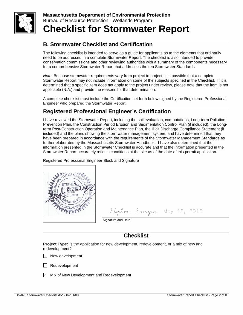
B. Stormwater Checklist and Certification
The following checklist is intended to serve as a guide for applicants as to the elements that ordinarily need to be addressed in a complete Stormwater Report. The checklist is also intended to provide conservation commissions and other reviewing authorities with a summary of the components necessary for a comprehensive Stormwater Report that addresses the ten Stormwater Standards.
Note: Because stormwater requirements vary from project to project, it is possible that a complete Stormwater Report may not include information on some of the subjects specified in the Checklist. If it is determined that a specific item does not apply to the project under review, please note that the item is not applicable (N.A.) and provide the reasons for that determination.
A complete checklist must include the Certification set forth below signed by the Registered Professional Engineer who prepared the Stormwater Report.
Registered Professional Engineer’s Certification
I have reviewed the Stormwater Report, including the soil evaluation, computations, Long-term Pollution Prevention Plan, the Construction Period Erosion and Sedimentation Control Plan (if included), the Long-term Post-Construction Operation and Maintenance Plan, the Illicit Discharge Compliance Statement (if included) and the plans showing the stormwater management system, and have determined that they have been prepared in accordance with the requirements of the Stormwater Management Standards as further elaborated by the Massachusetts Stormwater Handbook. I have also determined that the information presented in the Stormwater Checklist is accurate and that the information presented in the Stormwater Report accurately reflects conditions at the site as of the date of this permit application.
Registered Professional Engineer Block and Signature
Signature and Date
Checklist
Project Type: Is the application for new development, redevelopment, or a mix of new and redevelopment?
New development
Redevelopment
Mix of New Development and Redevelopment
Stephen Sawyer May 15, 2018
15-073 Stormwater Checklist.doc • 04/01/08 Stormwater Report Checklist • Page 3 of 8
Massachusetts Department of Environmental Protection Bureau of Resource Protection - Wetlands Program
Checklist for Stormwater Report
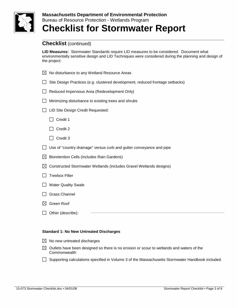
Checklist (continued) LID Measures: Stormwater Standards require LID measures to be considered. Document what
environmentally sensitive design and LID Techniques were considered during the planning and design of the project:
No disturbance to any Wetland Resource Areas
Site Design Practices (e.g. clustered development, reduced frontage setbacks)
Reduced Impervious Area (Redevelopment Only)
Minimizing disturbance to existing trees and shrubs
LID Site Design Credit Requested:
Credit 1
Credit 2
Credit 3
Use of “country drainage” versus curb and gutter conveyance and pipe
Bioretention Cells (includes Rain Gardens)
Constructed Stormwater Wetlands (includes Gravel Wetlands designs)
Treebox Filter
Water Quality Swale
Grass Channel
Green Roof
Other (describe):
Standard 1: No New Untreated Discharges
No new untreated discharges
Outlets have been designed so there is no erosion or scour to wetlands and waters of the Commonwealth
Supporting calculations specified in Volume 3 of the Massachusetts Stormwater Handbook included.

15-073 Stormwater Checklist.doc • 04/01/08 Stormwater Report Checklist • Page 4 of 8
Massachusetts Department of Environmental Protection Bureau of Resource Protection - Wetlands Program
Checklist for Stormwater Report
Checklist (continued)
Standard 2: Peak Rate Attenuation Standard 2 waiver requested because the project is located in land subject to coastal storm flowage
and stormwater discharge is to a wetland subject to coastal flooding. Evaluation provided to determine whether off-site flooding increases during the 100-year 24-hour
storm.
Calculations provided to show that post-development peak discharge rates do not exceed pre-development rates for the 2-year and 10-year 24-hour storms. If evaluation shows that off-site flooding increases during the 100-year 24-hour storm, calculations are also provided to show that post-development peak discharge rates do not exceed pre-development rates for the 100-year 24-hour storm.
Standard 3: Recharge
Soil Analysis provided.
Required Recharge Volume calculation provided.
Required Recharge volume reduced through use of the LID site Design Credits.
Sizing the infiltration, BMPs is based on the following method: Check the method used.
Static Simple Dynamic Dynamic Field1
Runoff from all impervious areas at the site discharging to the infiltration BMP.
Runoff from all impervious areas at the site is not discharging to the infiltration BMP and calculations
are provided showing that the drainage area contributing runoff to the infiltration BMPs is sufficient to generate the required recharge volume.
Recharge BMPs have been sized to infiltrate the Required Recharge Volume.
Recharge BMPs have been sized to infiltrate the Required Recharge Volume only to the maximum extent practicable for the following reason:
Site is comprised solely of C and D soils and/or bedrock at the land surface
M.G.L. c. 21E sites pursuant to 310 CMR 40.0000
Solid Waste Landfill pursuant to 310 CMR 19.000
Project is otherwise subject to Stormwater Management Standards only to the maximum extent practicable.
Calculations showing that the infiltration BMPs will drain in 72 hours are provided.
Property includes a M.G.L. c. 21E site or a solid waste landfill and a mounding analysis is included.
1 80% TSS removal is required prior to discharge to infiltration BMP if Dynamic Field method is used.

15-073 Stormwater Checklist.doc • 04/01/08 Stormwater Report Checklist • Page 5 of 8
Massachusetts Department of Environmental Protection Bureau of Resource Protection - Wetlands Program
Checklist for Stormwater Report
Checklist (continued)
Standard 3: Recharge (continued)
The infiltration BMP is used to attenuate peak flows during storms greater than or equal to the 10-year 24-hour storm and separation to seasonal high groundwater is less than 4 feet and a mounding analysis is provided.
Documentation is provided showing that infiltration BMPs do not adversely impact nearby wetland resource areas.
Standard 4: Water Quality
The Long-Term Pollution Prevention Plan typically includes the following: • Good housekeeping practices; • Provisions for storing materials and waste products inside or under cover; • Vehicle washing controls; • Requirements for routine inspections and maintenance of stormwater BMPs; • Spill prevention and response plans; • Provisions for maintenance of lawns, gardens, and other landscaped areas; • Requirements for storage and use of fertilizers, herbicides, and pesticides; • Pet waste management provisions; • Provisions for operation and management of septic systems; • Provisions for solid waste management; • Snow disposal and plowing plans relative to Wetland Resource Areas; • Winter Road Salt and/or Sand Use and Storage restrictions; • Street sweeping schedules; • Provisions for prevention of illicit discharges to the stormwater management system; • Documentation that Stormwater BMPs are designed to provide for shutdown and containment in the
event of a spill or discharges to or near critical areas or from LUHPPL; • Training for staff or personnel involved with implementing Long-Term Pollution Prevention Plan; • List of Emergency contacts for implementing Long-Term Pollution Prevention Plan.
A Long-Term Pollution Prevention Plan is attached to Stormwater Report and is included as an attachment to the Wetlands Notice of Intent.
Treatment BMPs subject to the 44% TSS removal pretreatment requirement and the one inch rule for calculating the water quality volume are included, and discharge:
is within the Zone II or Interim Wellhead Protection Area
is near or to other critical areas
is within soils with a rapid infiltration rate (greater than 2.4 inches per hour)
involves runoff from land uses with higher potential pollutant loads.
The Required Water Quality Volume is reduced through use of the LID site Design Credits.
Calculations documenting that the treatment train meets the 80% TSS removal requirement and, if applicable, the 44% TSS removal pretreatment requirement, are provided.

15-073 Stormwater Checklist.doc • 04/01/08 Stormwater Report Checklist • Page 6 of 8
Massachusetts Department of Environmental Protection Bureau of Resource Protection - Wetlands Program
Checklist for Stormwater Report
Checklist (continued)
Standard 4: Water Quality (continued)
The BMP is sized (and calculations provided) based on:
The ½” or 1” Water Quality Volume or The equivalent flow rate associated with the Water Quality Volume and documentation is
provided showing that the BMP treats the required water quality volume.
The applicant proposes to use proprietary BMPs, and documentation supporting use of proprietary BMP and proposed TSS removal rate is provided. This documentation may be in the form of the propriety BMP checklist found in Volume 2, Chapter 4 of the Massachusetts Stormwater Handbook and submitting copies of the TARP Report, STEP Report, and/or other third party studies verifying performance of the proprietary BMPs.
A TMDL exists that indicates a need to reduce pollutants other than TSS and documentation showing that the BMPs selected are consistent with the TMDL is provided.
Standard 5: Land Uses With Higher Potential Pollutant Loads (LUHPPLs)
The NPDES Multi-Sector General Permit covers the land use and the Stormwater Pollution
Prevention Plan (SWPPP) has been included with the Stormwater Report.
The NPDES Multi-Sector General Permit covers the land use and the SWPPP will be submitted prior to the discharge of stormwater to the post-construction stormwater BMPs.
The NPDES Multi-Sector General Permit does not cover the land use.
LUHPPLs are located at the site and industry specific source control and pollution prevention measures have been proposed to reduce or eliminate the exposure of LUHPPLs to rain, snow, snow melt and runoff, and been included in the long term Pollution Prevention Plan.
All exposure has been eliminated.
All exposure has not been eliminated and all BMPs selected are on MassDEP LUHPPL list.
The LUHPPL has the potential to generate runoff with moderate to higher concentrations of oil and grease (e.g. all parking lots with >1000 vehicle trips per day) and the treatment train includes an oil grit separator, a filtering bioretention area, a sand filter or equivalent.
Standard 6: Critical Areas
The discharge is near or to a critical area and the treatment train includes only BMPs that MassDEP has approved for stormwater discharges to or near that particular class of critical area.
Critical areas and BMPs are identified in the Stormwater Report.

15-073 Stormwater Checklist.doc • 04/01/08 Stormwater Report Checklist • Page 7 of 8
Massachusetts Department of Environmental Protection Bureau of Resource Protection - Wetlands Program
Checklist for Stormwater Report
Checklist (continued)
Standard 7: Redevelopments and Other Projects Subject to the Standards only to the maximum extent practicable
The project is subject to the Stormwater Management Standards only to the maximum Extent Practicable as a:
Limited Project
Small Residential Projects: 5-9 single family houses or 5-9 units in a multi-family development provided there is no discharge that may potentially affect a critical area.
Small Residential Projects: 2-4 single family houses or 2-4 units in a multi-family development with a discharge to a critical area
Marina and/or boatyard provided the hull painting, service and maintenance areas are protected from exposure to rain, snow, snow melt and runoff
Bike Path and/or Foot Path
Redevelopment Project
Redevelopment portion of mix of new and redevelopment.
Certain standards are not fully met (Standard No. 1, 8, 9, and 10 must always be fully met) and an explanation of why these standards are not met is contained in the Stormwater Report.
The project involves redevelopment and a description of all measures that have been taken to improve existing conditions is provided in the Stormwater Report. The redevelopment checklist found in Volume 2 Chapter 3 of the Massachusetts Stormwater Handbook may be used to document that the proposed stormwater management system (a) complies with Standards 2, 3 and the pretreatment and structural BMP requirements of Standards 4-6 to the maximum extent practicable and (b) improves existing conditions.
Standard 8: Construction Period Pollution Prevention and Erosion and Sedimentation Control
A Construction Period Pollution Prevention and Erosion and Sedimentation Control Plan must include the following information:
• Narrative; • Construction Period Operation and Maintenance Plan; • Names of Persons or Entity Responsible for Plan Compliance; • Construction Period Pollution Prevention Measures; • Erosion and Sedimentation Control Plan Drawings; • Detail drawings and specifications for erosion control BMPs, including sizing calculations; • Vegetation Planning; • Site Development Plan; • Construction Sequencing Plan; • Sequencing of Erosion and Sedimentation Controls; • Operation and Maintenance of Erosion and Sedimentation Controls; • Inspection Schedule; • Maintenance Schedule; • Inspection and Maintenance Log Form.
A Construction Period Pollution Prevention and Erosion and Sedimentation Control Plan containing the information set forth above has been included in the Stormwater Report.

15-073 Stormwater Checklist.doc • 04/01/08 Stormwater Report Checklist • Page 8 of 8
Massachusetts Department of Environmental Protection Bureau of Resource Protection - Wetlands Program
Checklist for Stormwater Report
Checklist (continued)
Standard 8: Construction Period Pollution Prevention and Erosion and Sedimentation Control (continued)
The project is highly complex and information is included in the Stormwater Report that explains why it is not possible to submit the Construction Period Pollution Prevention and Erosion and Sedimentation Control Plan with the application. A Construction Period Pollution Prevention and Erosion and Sedimentation Control has not been included in the Stormwater Report but will be submitted before land disturbance begins.
The project is not covered by a NPDES Construction General Permit.
The project is covered by a NPDES Construction General Permit and a copy of the SWPPP is in the Stormwater Report.
The project is covered by a NPDES Construction General Permit but no SWPPP been submitted. The SWPPP will be submitted BEFORE land disturbance begins.
Standard 9: Operation and Maintenance Plan
The Post Construction Operation and Maintenance Plan is included in the Stormwater Report and includes the following information:
Name of the stormwater management system owners;
Party responsible for operation and maintenance;
Schedule for implementation of routine and non-routine maintenance tasks;
Plan showing the location of all stormwater BMPs maintenance access areas;
Description and delineation of public safety features;
Estimated operation and maintenance budget; and
Operation and Maintenance Log Form.
The responsible party is not the owner of the parcel where the BMP is located and the Stormwater Report includes the following submissions:
A copy of the legal instrument (deed, homeowner’s association, utility trust or other legal entity) that establishes the terms of and legal responsibility for the operation and maintenance of the project site stormwater BMPs;
A plan and easement deed that allows site access for the legal entity to operate and maintain BMP functions.
Standard 10: Prohibition of Illicit Discharges
The Long-Term Pollution Prevention Plan includes measures to prevent illicit discharges;
An Illicit Discharge Compliance Statement is attached;
NO Illicit Discharge Compliance Statement is attached but will be submitted prior to the discharge of any stormwater to post-construction BMPs.

3 Perkins Way
2. Project Overview
Introduction Bradford & Bigelow Realty, LLC, is seeking to expand the existing building and make associated improvements to the property at 3 Perkins Way. This expansion is necessary to accommodate a new printing press and fulfillment warehouse that is critical component in Bradford & Bigelow’s continuing business in the competitive printing and publishing business. In order to install the printing press, which is well over a hundred feet long, a small addition is necessary in the southeastern corner of the building. The fulfillment warehouse expansion will be located at the northern end of the building. The project is partially located within both the buffer zone to wetlands and riverfront.
Existing Conditions The existing site is comprised of City of Newburyport Assessors tax map parcel Map 78 Lot Parcel 6. The access to property is from Perkins Way. Elevations on the property range from 11 to 21 based upon the datum NAVD 1988.
The lot itself covers an area of 386,304 square feet. There are wetlands located in various location on and off site surrounding the developed portion of the lot. On site there are wetlands to the south, east, and west of the building, along with a small wetland area at the northern end. To the northeast, there is an unnamed tributary to the Little River. This tributary is shown on USGS maps as perennial. The existing building is a one-story metal building approximately 97,233 square feet. The building is occupied by Bradford & Bigelow, which is a typesetting, digital and offset printing company.
Project Description The proposal is to construct two (2) additions to the existing building. Bradford & Bigelow is outgrowing its existing building and requires additional warehouse storage space as well as room to install a new printing press.
The larger addition, located at the northern end of the building will cover an area of 41,105.5 square feet. The northeastern corner is within the outer riparian zone, covering an area of 4,618 square feet of riverfront. The Northwestern corner is within the outer buffer zone to wetlands.
The smaller addition will cover an area of 1,525 square feet and is proposed for the southeasterly portion of the building. This bump-out is intended to accommodate for the long length of the new printing press which will be installed lengthwise near the southerly building wall. This addition extends partially within a previously disturbed portion of the 25 foot no-disturb-zone.
The project proposes the following drainage mitigation measures;
1. Green roof on the small addition.
2. Water quality pretreatment unit for the loading dock
3. Constructed Pocket Wetland for the loading dock and large building addition
4. New rain gardens cut into the existing parking lot.

3 Perkins Way
Utilities No new utilities are proposed with the building addition. The new building addition will require relocating a 8” water main.
3. Stormwater Management
Introduction The current site consists of two subcatchment areas. The total area being analyzed is approximately 8.86 acres. The area being analyzed is mostly developed with a portion of brush/grass area on the north side of the property.
According to the USDA Soil Survey, the majority of on-site soils consist of Buxton and Scantic Silt Loam with a Hydrologic Soil Group “D”. A detailed description of the on-site soils is included as Appendix A.
The proposed additions increases impervious areas; multiple BMP’s will be implemented. With the use of these BMP’s, the project will comply with the ten standards of the DEP Stormwater Handbook.
Stormwater from the large building addition will be directed a large bio retention area providing mitigation for peak discharge rates. There is a small increase (550 sf) of pavement to accomadate three proposed loading docks. This is offset by removing 1,570 sf of bituminous concrete parking surface to provide five new rain garden areas. The loading dock is directed to the bio-retention area with pretreatment provided by a water quality unit.
A green roof is proposed on the smaller building addition.
Consistency with the DEP Stormwater Management Policy The project is new development and therefore must meet all ten of the Stormwater Management Standards. Each of the standards of the DEP Stormwater Handbook and how the project meets or exceeds them is discussed below.
Standard 1 – Untreated Stormwater
Standard 1 states that “No new stormwater conveyances (e.g. outfalls) will discharge untreated stormwater directly to or cause erosion in wetlands or waters of the Commonwealth.”
The proposed drainage system does not include new conveyances that discharge directly without pre-treatment. The project propos Several BMP’s are proposed to treat stormwater and to prevent any erosion to the surrounding Resource Areas. Since no new conveyances will directly discharge untreated stormwater, the project meets this standard.
Standard 2 – Post Development Peak Discharge Rates
Standard 2 states that “Stormwater management systems shall be designed so that post-development peak discharge rates do not exceed pre-development peak discharge rates.”

3 Perkins Way
The site was analyzed under both the existing and proposed conditions to compare the pre and post development peak discharge rates at design points leaving the property. Overall there is one design point for this site with the runoff directed to the Little River and small tributary to the The analysis divides the site into several subcatchments that discharge to different design points at the borders of the site. Each point was analyzed to ensure that there is no impact on abutting properties as a result of the project. A detailed description of both the existing conditions hydrology and proposed conditions hydrology is described below. A copy of the HydroCAD printouts for both existing and proposed conditions is included in Appendix C.
Existing Conditions Hydrology
The existing hydrology on site is divided into two area. Subcatchments EX-1 flows to the south into a Perkins Way drainage system. EX 2 flows to the perennial stream north of the property. This perennial stream is a tributary to the Little River. Both areas eventually discharge to the Little River
Proposed Conditions Hydrology
Proposed Subcatchment P1; This subcatchment consists of existing parking, walks and roof that drains to Perkins Way. The only proposed work in this area is the small building addition (1,523 sf). A green roof is proposed here. Improvements are proposed within the large existing parking lot. Five small rain garden islands are proposed to capture and provided treatment within this existing parking lot. A portion of this subcatchment area is redirected to P2.
Proposed Subcatchment P2; This subcatchment consists of the large building addition and small increased paved area to accommodate the new loading docks. This area is directed to a large bio retention basin north of the proposed addition.
Summary
Mitigation is provided for the proposed building addition and loading dock. The mitigation measures includes a green roof on the small addition and large bio retention basin. These mitigation measures result in a stormwater management system that meets the requirements of Standard 2. The project does not increase flow rate to either of the two design points. A summary of the pre and post development discharge rates is shown on Table 1 below.

3 Perkins Way
Table 2: Existing and Proposed Peak Discharge Rate Comparison at Design Points
DESIGN POINT 1 – To Perkins Way
2 Year Storm (3.1 in) 10 Year Storm (4.70in) 8.3
Design Point
Existing (cfs)
Proposed (cfs) Existing (cfs) Existing
(cfs) Proposed
(cfs)
1
12.27 12.25 19.89 19.60 36.75 35.84
DESIGN POINT 2 – To Perennial Stream North of Property
2 Year Storm (3.1 in) 10 Year Storm (4.70in) 8.3
Design Point
Existing (cfs)
Proposed (cfs) Existing (cfs) Existing
(cfs) Proposed
(cfs)
2
1.80 1.68 3.62 3.46 8.00 7.58
Since the proposed project is designed so that post-development peak discharge rates do not exceed pre-development peak discharge rates, the project is in compliance with Standard 2. Standard 3 – Recharge to Groundwater
Standard 3 states that “Loss of annual recharge to groundwater shall be eliminated or minimized through the use of infiltration measures including environmentally sensitive site design, low impact development techniques, stormwater best management practices, and good operation and maintenance. At a minimum, the annual recharge from the post-development site shall approximate the annual recharge from pre-development conditions based on soil type. This condition is met when the stormwater management system is designed to infiltrate the required recharge volume as determined in accordance with the Massachusetts Stormwater Handbook.”
The volume of the recharge system was calculated according to the Massachusetts Stormwater Handbook. The proposed site design increases impervious area by 43,183 square feet. For this calculation, all impervious areas will be counted as being on Hydrologic Group D soils having a volume requirement of 0.1 inches x the area of impervious cover. This gives a required recharge volume of 359 cubic feet. The sump of the proposed rain gardens provide 780 cubic feet of recharge volume.

3 Perkins Way
Standard 4 – Removal of 80% Total Suspended Solids (TSS)
Standard 4 states that “Stormwater management systems shall be designed to remove 80% of the average annual post-construction load of Total Suspended Solids (TSS). This Standard is met when: (a) Suitable practices for source control and pollution prevention are identified in long-term pollution prevention plan, and thereafter implemented and maintained; (b) Structural stormwater best management practices are sized to capture the required water quality volume determined in accordance with the Massachusetts Stormwater Handbook; and (c) Pretreatment is provided in accordance with the Massachusetts Stormwater Handbook.”
Removal of Total Suspended Solids (TSS) is proposed for the developed areas of the site. TSS removal is accomplished by the combination of the following structural and non-structural BMPs:
Design Point 1 – There are no new paved areas directed to Design Point 1. Five Rain Gardens are proposed to be cut into the existing parking lot to provide water quality improvements. Portions of the existing parking lot will be intercepted by sheet flow within the new rain gardens.
Design Point 2 – There is 1,470 new or regraded existing pavement at the northeast corner of the existing parking lot. This area requires 1/2” water quality volume (WQV) over the new and regraded loading dock ramp. The total impervious surface to be treated contributing to this basin is 1,470 sf with a required WQV of 62 cubic feet. The Constructed Pocket Wetland provides 306 cubic feet of water quality volume between elevation 10.50 and invert out of basin at 11.25. Pretreatment is provided for the basin by passing the stormwater thru a water quality unit. 90% TSS removal is provided for this drainage area based upon MA Stormwater Guidelines for Bio Retention Basins.
Standard 5 – Land Uses with Higher Potential Pollutant Loads
Standard 5 states that “For land uses with higher potential pollutant loads, source control and pollution prevention shall be implemented in accordance with the Massachusetts Stormwater Handbook to eliminate or reduce the discharge of stormwater runoff from such land uses to the maximum extent practicable. If through source control and/or pollution prevention all land uses with higher potential pollutant loads cannot be completely protected from exposure to rain, snow, snow melt, and stormwater runoff, the proponent shall use the specific structural stormwater BMPs determined by the Department to be suitable for such uses as provided in the Massachusetts Stormwater Handbook.”
The project use is not a Land Use with Higher Potential Pollutant Loads. Therefore, Standard 5 is not applicable to this project.
Standard 6 – Critical Areas
Standard 6 states that “Stormwater discharges within the Zone II or Interim Wellhead Protection Area of a public water supply and stormwater discharges near or to any other critical area require the use of the specific source control and pollution prevention measures and the specific structural stormwater best management practices determined by the Department to be suitable for managing discharges to such areas as provided in the Massachusetts Stormwater Handbook.”

3 Perkins Way
The project’s is not located in estimated habitat or any critical area.
Standard 7 - Redevelopment
Standard 7 states that “A redevelopment project is required to meet the following Stormwater Management Standards only to the maximum extent practicable: Standard 2, Standard 3, and the pretreatment and structural best management practice requirements of Standards 4, 5 and 6. Existing stormwater discharges shall comply with Standard 1 only to the maximum extent practicable. A redevelopment project shall also comply with all other requirements of the Stormwater Management Standards and improve existing conditions.”
The proposed project is in undeveloped area and therefore it does not meet the definition of a redevelopment, Standard 7 does not apply.
Standard 8 – Erosion and Sedimentation Controls
Standard 8 states that “A plan to control construction related impacts including erosion, sedimentation and other pollutant sources during construction and land disturbance activities (construction period erosion, sedimentation, and pollution prevention plan) shall be developed and implemented.”
A Stormwater Pollution Prevention Plan for the Project will be submitted prior to any land disturbance on the site.
Standard 9 – Operation and Maintenance Plans
Standard 9 states: “A long-term operation and maintenance plan shall be developed and implemented to ensure that stormwater management systems function as designed. “
A long-term operation and maintenance plan is included in Appendix E. The Plan includes provisions for Construction-Phase measures, as well as long term maintenance and inspections. Therefore the Project complies with Standard 9.
Standard 10 – Illicit Discharges to Drainage System
Standard 10 states: “All illicit discharges to the stormwater management system are prohibited.”
There are no known or suspected illicit discharges to the stormwater management system at the project site. Therefore the Project complies with Standard 10.

3 Perkins Way

3 Perkins Way
Appendix A
USDA NRCS Soil Map & Soil Logs

Hydrologic Soil Group—Essex County, Massachusetts, Northern Part
Natural ResourcesConservation Service
Web Soil SurveyNational Cooperative Soil Survey
3/14/2018Page 1 of 4
4739
920
4739
960
4740
000
4740
040
4740
080
4740
120
4740
160
4740
200
4740
240
4739
920
4739
960
4740
000
4740
040
4740
080
4740
120
4740
160
4740
200
4740
240
345830 345870 345910 345950 345990 346030 346070
345830 345870 345910 345950 345990 346030 346070
42° 47' 57'' N70
° 5
3' 7
'' W42° 47' 57'' N
70° 5
2' 5
5'' W
42° 47' 46'' N
70° 5
3' 7
'' W
42° 47' 46'' N
70° 5
2' 5
5'' W
N
Map projection: Web Mercator Corner coordinates: WGS84 Edge tics: UTM Zone 19N WGS840 50 100 200 300
Feet0 25 50 100 150
MetersMap Scale: 1:1,720 if printed on A portrait (8.5" x 11") sheet.
Soil Map may not be valid at this scale.
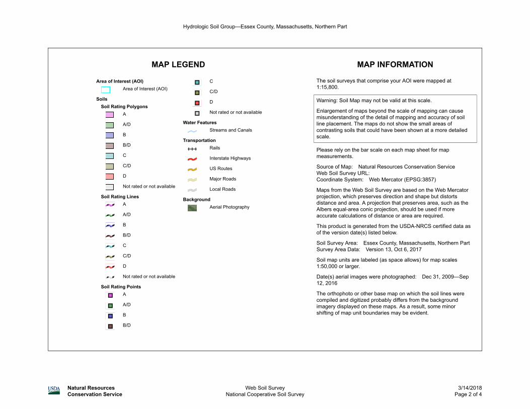
MAP LEGEND MAP INFORMATION
Area of Interest (AOI)Area of Interest (AOI)
SoilsSoil Rating Polygons
A
A/D
B
B/D
C
C/D
D
Not rated or not available
Soil Rating LinesA
A/D
B
B/D
C
C/D
D
Not rated or not available
Soil Rating PointsA
A/D
B
B/D
C
C/D
D
Not rated or not available
Water FeaturesStreams and Canals
TransportationRails
Interstate Highways
US Routes
Major Roads
Local Roads
BackgroundAerial Photography
The soil surveys that comprise your AOI were mapped at 1:15,800.
Warning: Soil Map may not be valid at this scale.
Enlargement of maps beyond the scale of mapping can cause misunderstanding of the detail of mapping and accuracy of soil line placement. The maps do not show the small areas of contrasting soils that could have been shown at a more detailed scale.
Please rely on the bar scale on each map sheet for map measurements.
Source of Map: Natural Resources Conservation ServiceWeb Soil Survey URL: Coordinate System: Web Mercator (EPSG:3857)
Maps from the Web Soil Survey are based on the Web Mercator projection, which preserves direction and shape but distorts distance and area. A projection that preserves area, such as the Albers equal-area conic projection, should be used if more accurate calculations of distance or area are required.
This product is generated from the USDA-NRCS certified data as of the version date(s) listed below.
Soil Survey Area: Essex County, Massachusetts, Northern PartSurvey Area Data: Version 13, Oct 6, 2017
Soil map units are labeled (as space allows) for map scales 1:50,000 or larger.
Date(s) aerial images were photographed: Dec 31, 2009—Sep 12, 2016
The orthophoto or other base map on which the soil lines were compiled and digitized probably differs from the background imagery displayed on these maps. As a result, some minor shifting of map unit boundaries may be evident.
Hydrologic Soil Group—Essex County, Massachusetts, Northern Part
Natural ResourcesConservation Service
Web Soil SurveyNational Cooperative Soil Survey
3/14/2018Page 2 of 4

Hydrologic Soil Group
Map unit symbol Map unit name Rating Acres in AOI Percent of AOI
16A Scantic silt loam, 0 to 3 percent slopes
C/D 7.3 62.9%
228B Buxton silt loam, 3 to 8 percent slopes
D 3.6 31.5%
711B Charlton-Rock outcrop-Hollis complex, 3 to 8 percent slopes
A 0.6 5.5%
Totals for Area of Interest 11.5 100.0%
Description
Hydrologic soil groups are based on estimates of runoff potential. Soils are assigned to one of four groups according to the rate of water infiltration when the soils are not protected by vegetation, are thoroughly wet, and receive precipitation from long-duration storms.
The soils in the United States are assigned to four groups (A, B, C, and D) and three dual classes (A/D, B/D, and C/D). The groups are defined as follows:
Group A. Soils having a high infiltration rate (low runoff potential) when thoroughly wet. These consist mainly of deep, well drained to excessively drained sands or gravelly sands. These soils have a high rate of water transmission.
Group B. Soils having a moderate infiltration rate when thoroughly wet. These consist chiefly of moderately deep or deep, moderately well drained or well drained soils that have moderately fine texture to moderately coarse texture. These soils have a moderate rate of water transmission.
Group C. Soils having a slow infiltration rate when thoroughly wet. These consist chiefly of soils having a layer that impedes the downward movement of water or soils of moderately fine texture or fine texture. These soils have a slow rate of water transmission.
Group D. Soils having a very slow infiltration rate (high runoff potential) when thoroughly wet. These consist chiefly of clays that have a high shrink-swell potential, soils that have a high water table, soils that have a claypan or clay layer at or near the surface, and soils that are shallow over nearly impervious material. These soils have a very slow rate of water transmission.
If a soil is assigned to a dual hydrologic group (A/D, B/D, or C/D), the first letter is for drained areas and the second is for undrained areas. Only the soils that in their natural condition are in group D are assigned to dual classes.
Hydrologic Soil Group—Essex County, Massachusetts, Northern Part
Natural ResourcesConservation Service
Web Soil SurveyNational Cooperative Soil Survey
3/14/2018Page 3 of 4


1
SOIL SUITABILITY ASSESSMENT REPORT
COMMONWEALTH OF MASSACHUSETTS
NEWBURYPORT, MASSACHUSETTS SEASONAL HIGH GROUNDWATER TABLE ELEVATION DETERMINATION
SITE INFORMATION Bradford & Bigelow, Inc. Street Address: 3 Perkins Way Town: Newburyport State: Massachusetts Zip Code: 01950
County: Essex Land Use: Zoned Residential Latitude: ~42o47’55.6
” N Longitude: ~70
o53’04.4”W Elevation: ~25-30’
PUBLISHED SOIL DATA AND MAP UNIT DESCRIPTION
Physiographic Division: Appalachian Highlands Physio. Province: New England Physio. Section: Seaboard lowland section
Soil map unit: 228B – Buxton silt loam (fine, mixed, mesic, aquicic Dystric Eutrochrepts), 3-8% slopes
NRCS/USDA web soil survey: Essex County, Massachusetts, Northern part. Map Scale: 1:300’
Hydric or upland soil: Upland soil Average depth to water table: 12 - 36” Depth to restrictive feature: >80”
Frequency of flooding: None Frequency of ponding: None Available water capacity: High (~9.7”) Runoff Class: Low
Drainage Class: Moderately well drained Hydrologic Soil Group: D Ksat: Low to moderate (0.00 – 0.20 in/hr)
Soil limitations: Low permeability, shallow seasonal and apparent groundwater elevations, firm & dense
substratum, high available water capacity, low Ksat.
WETLAND AREA & USGS WELL MEASUREMENTS
National Wetland Inventory Map: NA Wetlands Conservancy Program: NA Bordering vegetative wetland: >200 feet
Current Water Resource Condition (USGS): Well Site # 424520070562401- MA-NIW 27 Newbury, MA
Well completed in Sand and gravel aquifers and ice-contact deposits, including kames and eskers.
Well depth: 19.8 feet Land surface altitude: 55.00 feet above NGVD29 Latitude: ~42o45’19.3
” N Longitude: ~70
o56’22.1”
Most recent data value: 4.08’ on 04/15/18 (depth to water level in feet below land surface). Range: Normal
SURFICIAL GEOLOGY: Surficial geology: Qmc: Late Pleistocene, Wisconsin Stage – Marine and estuarine deposits
Geologic parent material: Glaciomarine: silty clay deposits Geomorphic landform: Coastal plain: marine terrace
Slope aspect: Northeast Landform position (2D): Footslope Landform position (3D): Sideslope
Slope gradient: ~00-04% Down slope shape: Linear Across slope shape: Concave Slope complexity: Simple
Bedrock outcropping in vicinity: Not observed Glacial erratics in vicinity: None observed
Bedrock Type: Newburyport Volcanic Complex: Lower Devonian, Porphyritic andesite, includes tuffaceous mudstone beds
containing fossils of Late Silurian through Early Devonian age.

2
TP18-1 DEEP OBSERVATION HOLE 3 Perkins Way, Newburyport, Massachusetts
Date: April 14, 2018 Time: 10:10 Weather: Partly cloudy, ~45-50oF, westerly wind
Landscape: Upland Landform: Marine terrace Position on landscape: Shoulder of slope
Slope aspect: Northerly Slope (%): 00- 03% Slope complexity: Simple Land Cover: Meadow grass
Property line: 10+ feet Drainage way: 50
+ feet Drinking water well: 100
+ feet Abutting septic system: 50
+ feet
Wetlands: 100+ feet Public water supply reservoir: 400
+ feet Tributary to reservoir: 200
+ feet
Open water body: 400+ feet
SOIL PROFILE ► TP18-1
Depth to bedrock: >78” Seasonal High Groundwater Table: 26” Apparent water table: 41”
Certification
I certify that I am currently approved by the Department of Environmental Protection pursuant to 310 CMR 15.017 to conduct
evaluations and that the above analysis has been performed by me consistent with the required training, expertise and experience described in
310 CMR 15.017. I further certify that the results of my soil evaluation, as indicated in the attached Soil Evaluation Form, are accurate and in accordance
with 310 CMR 15.017. Date of Soil Evaluator Certification: June 1998.
Alexander F. Parker #1848 April 14, 2018 Massachusetts Evaluator & Certification number Date of Soil Evaluation
Depth below
land surface (inches)
Soil
Horizon/
Layer
Soil Texture (USDA/ NRCS)
Soil Color (Munsell)
Redoxomorphic
Features/
ESHGWT
Consistence, grade, size, structure, grain size, soil moisture state,
roots, horizon boundary, clasts, stratification, artifacts, restrictive
features, etc.
00” → 05”
Ap
Sandy Loam
10YR 3/2
very dark
grayish brown
none observed
Very friable; moderate-grade fine to medium sub-angular granular
structure; somewhat cohesive; fine grained mineral content; poorly
graded; damp; slightly sticky; nonplastic; many fine grass roots;
free of clasts; diffuse smooth boundary.
05” → 40”
^C
Silty Clay
Loam
2.5Y4/2 dark grayish
brown
@ 26”
(c,2,d)
5%
7.5YR5/8
10Y7/1
Anthropogenic layer. Filled and excavated material; firm; strong
massive structure; dense matrix; poorly graded; ribbons to
approximately 1.5”; very moist matrix (non-satiated); somewhat
sticky; slightly plastic; gritty matrix; free of clasts; abrupt wavy
boundary.
40” → 78”
2C
Silty Clay
5Y 4/2
olive gray
none observed
Firm; strong massive structure; dense cohesive matrix; sticky;
plastic; poorly graded; ribbons to approximately 2.5”; very fine
grained mineral content; slightly gritty; wet matrix (satiated) free
water present on ped face; apparent water observed at 41”; free of
clasts; no refusal at test hole depth.

3
TP18-2 DEEP OBSERVATION HOLE3 Perkins Way, Newburyport, Massachusetts
Date: April 14, 2018 Time: 10:40 Weather: Partly cloudy, ~45-50oF, westerly wind
Landscape: Upland Landform: Marine terrace Position on landscape: Shoulder of slope
Slope aspect: Northerly Slope (%): 00- 03% Slope complexity: Simple Land Cover: Meadow grass
Property line: 10+ feet Drainage way: 50
+ feet Drinking water well: 100
+ feet Abutting septic system: 50
+ feet
Wetlands: 100+ feet Public water supply reservoir: 400
+ feet Tributary to reservoir: 200
+ feet
Open water body: 400+ feet
SOIL PROFILE ► TP18-2
Depth to bedrock: >47” Seasonal High Groundwater Table: 16” Apparent water table: 15”
Certification
I certify that I am currently approved by the Department of Environmental Protection pursuant to 310 CMR 15.017 to conduct
evaluations and that the above analysis has been performed by me consistent with the required training, expertise and experience described in
310 CMR 15.017. I further certify that the results of my soil evaluation, as indicated in the attached Soil Evaluation Form, are accurate and in accordance
with 310 CMR 15.017. Date of Soil Evaluator Certification: June 1998.
Alexander F. Parker #1848 April 14, 2018 Massachusetts Evaluator & Certification number Date of Soil Evaluation
Depth below
land surface (inches)
Soil
Horizon/
Layer
Soil Texture (USDA/ NRCS)
Soil Color (Munsell)
Redoxomorphic
Features/
ESHGWT
Consistence, grade, size, structure, grain size, soil moisture state,
roots, horizon boundary, clasts, stratification, artifacts, restrictive
features, etc.
00” → 14”
Ap
Sandy Loam
10YR 3/2
very dark
grayish brown
none observed
Very friable; moderate-grade fine to medium sub-angular granular
structure; somewhat cohesive; fine grained mineral content; poorly
graded; damp; slightly sticky; nonplastic; many fine grass roots;
free of clasts; diffuse smooth boundary.
14” → 47”
2C
Silty Clay
5Y 4/3
olive
@ 16”
(c,2,d)
5%
7.5YR5/8
10Y7/1
Firm; strong massive structure; dense cohesive matrix; sticky;
plastic; poorly graded; ribbons to approximately 2.5”; very fine
grained mineral content; slightly gritty; wet matrix (satiated) free
water present on ped face; apparent water observed at 15”; free of
clasts; no refusal at test hole depth.
4
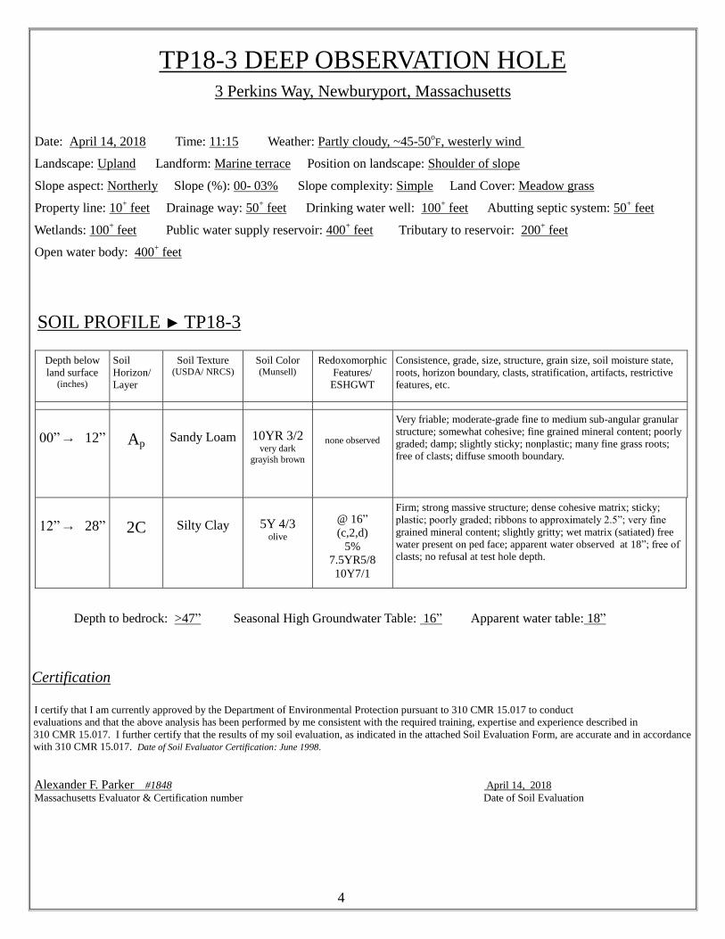
TP18-3 DEEP OBSERVATION HOLE3 Perkins Way, Newburyport, Massachusetts
Date: April 14, 2018 Time: 11:15 Weather: Partly cloudy, ~45-50oF, westerly wind
Landscape: Upland Landform: Marine terrace Position on landscape: Shoulder of slope
Slope aspect: Northerly Slope (%): 00- 03% Slope complexity: Simple Land Cover: Meadow grass
Property line: 10+ feet Drainage way: 50
+ feet Drinking water well: 100
+ feet Abutting septic system: 50
+ feet
Wetlands: 100+ feet Public water supply reservoir: 400
+ feet Tributary to reservoir: 200
+ feet
Open water body: 400+ feet
SOIL PROFILE ► TP18-3
Depth to bedrock: >47” Seasonal High Groundwater Table: 16” Apparent water table: 18”
Certification
I certify that I am currently approved by the Department of Environmental Protection pursuant to 310 CMR 15.017 to conduct
evaluations and that the above analysis has been performed by me consistent with the required training, expertise and experience described in
310 CMR 15.017. I further certify that the results of my soil evaluation, as indicated in the attached Soil Evaluation Form, are accurate and in accordance
with 310 CMR 15.017. Date of Soil Evaluator Certification: June 1998.
Alexander F. Parker #1848 April 14, 2018 Massachusetts Evaluator & Certification number Date of Soil Evaluation
Depth below
land surface (inches)
Soil
Horizon/
Layer
Soil Texture (USDA/ NRCS)
Soil Color (Munsell)
Redoxomorphic
Features/
ESHGWT
Consistence, grade, size, structure, grain size, soil moisture state,
roots, horizon boundary, clasts, stratification, artifacts, restrictive
features, etc.
00” → 12”
Ap
Sandy Loam
10YR 3/2
very dark
grayish brown
none observed
Very friable; moderate-grade fine to medium sub-angular granular
structure; somewhat cohesive; fine grained mineral content; poorly
graded; damp; slightly sticky; nonplastic; many fine grass roots;
free of clasts; diffuse smooth boundary.
12” → 28”
2C
Silty Clay
5Y 4/3
olive
@ 16”
(c,2,d)
5%
7.5YR5/8
10Y7/1
Firm; strong massive structure; dense cohesive matrix; sticky;
plastic; poorly graded; ribbons to approximately 2.5”; very fine
grained mineral content; slightly gritty; wet matrix (satiated) free
water present on ped face; apparent water observed at 18”; free of
clasts; no refusal at test hole depth.

5
TP18-4 DEEP OBSERVATION HOLE3 Perkins Way, Newburyport, Massachusetts
Date: April 14, 2018 Time: 11:47 Weather: Partly cloudy, ~45-50oF, westerly wind
Landscape: Upland Landform: Marine terrace Position on landscape: Shoulder of slope
Slope aspect: Northerly Slope (%): 00- 03% Slope complexity: Simple Land Cover: Meadow grass
Property line: 10+ feet Drainage way: 50
+ feet Drinking water well: 100
+ feet Abutting septic system: 50
+ feet
Wetlands: 100+ feet Public water supply reservoir: 400
+ feet Tributary to reservoir: 200
+ feet
Open water body: 400+ feet
SOIL PROFILE ► TP18-4
Depth to bedrock: >36” Seasonal High Groundwater Table: 20” Apparent water table: 19”
Certification
I certify that I am currently approved by the Department of Environmental Protection pursuant to 310 CMR 15.017 to conduct
evaluations and that the above analysis has been performed by me consistent with the required training, expertise and experience described in
310 CMR 15.017. I further certify that the results of my soil evaluation, as indicated in the attached Soil Evaluation Form, are accurate and in accordance
with 310 CMR 15.017. Date of Soil Evaluator Certification: June 1998.
Alexander F. Parker #1848 April 14, 2018 Massachusetts Evaluator & Certification number Date of Soil Evaluation
Depth below
land surface (inches)
Soil
Horizon/
Layer
Soil Texture (USDA/ NRCS)
Soil Color (Munsell)
Redoxomorphic
Features/
ESHGWT
Consistence, grade, size, structure, grain size, soil moisture state,
roots, horizon boundary, clasts, stratification, artifacts, restrictive
features, etc.
00” → 20”
Ap
Sandy Loam
10YR 3/2
very dark
grayish brown
none observed
Very friable; moderate-grade fine to medium sub-angular granular
structure; somewhat cohesive; fine grained mineral content; poorly
graded; damp; slightly sticky; nonplastic; many fine grass roots;
free of clasts; diffuse smooth boundary.
20” → 36”
2C
Silty Clay
5Y 4/3
olive
@ 20”
(c,2,d)
5%
7.5YR5/8
10Y7/1
Firm; strong massive structure; dense cohesive matrix; sticky;
plastic; poorly graded; ribbons to approximately 2.5”; very fine
grained mineral content; slightly gritty; wet matrix (satiated) free
water present on ped face; apparent water observed at 19”; free of
clasts; no refusal at test hole depth.

3 Perkins Way
Appendix B
HydroCAD Hydrology Printout

3 Perkins Way

EX1
Watershed 1A
EX2
Watershed 1B
1
12" Culvert- DP#1
2
River- DP#2
Drainage Diagram for 17-137 EXPrepared by Microsoft, Printed 3/21/2018
HydroCAD® 9.10 s/n 00884 © 2010 HydroCAD Software Solutions LLC
Subcat Reach Pond Link

17-137 EX Printed 3/21/2018Prepared by Microsoft
Page 2HydroCAD® 9.10 s/n 00884 © 2010 HydroCAD Software Solutions LLC
Area Listing (all nodes)
Area(sq-ft)
CN Description(subcatchment-numbers)
154,524 80 >75% Grass cover, Good, HSG D (EX1, EX2)45,085 98 Bordering Vegitaed Wetland, HSG D (EX1)89,163 98 Paved parking, HSG D (EX1)97,266 98 Roofs, HSG D (EX1)
17-137 EX Printed 3/21/2018Prepared by Microsoft
Page 3HydroCAD® 9.10 s/n 00884 © 2010 HydroCAD Software Solutions LLC
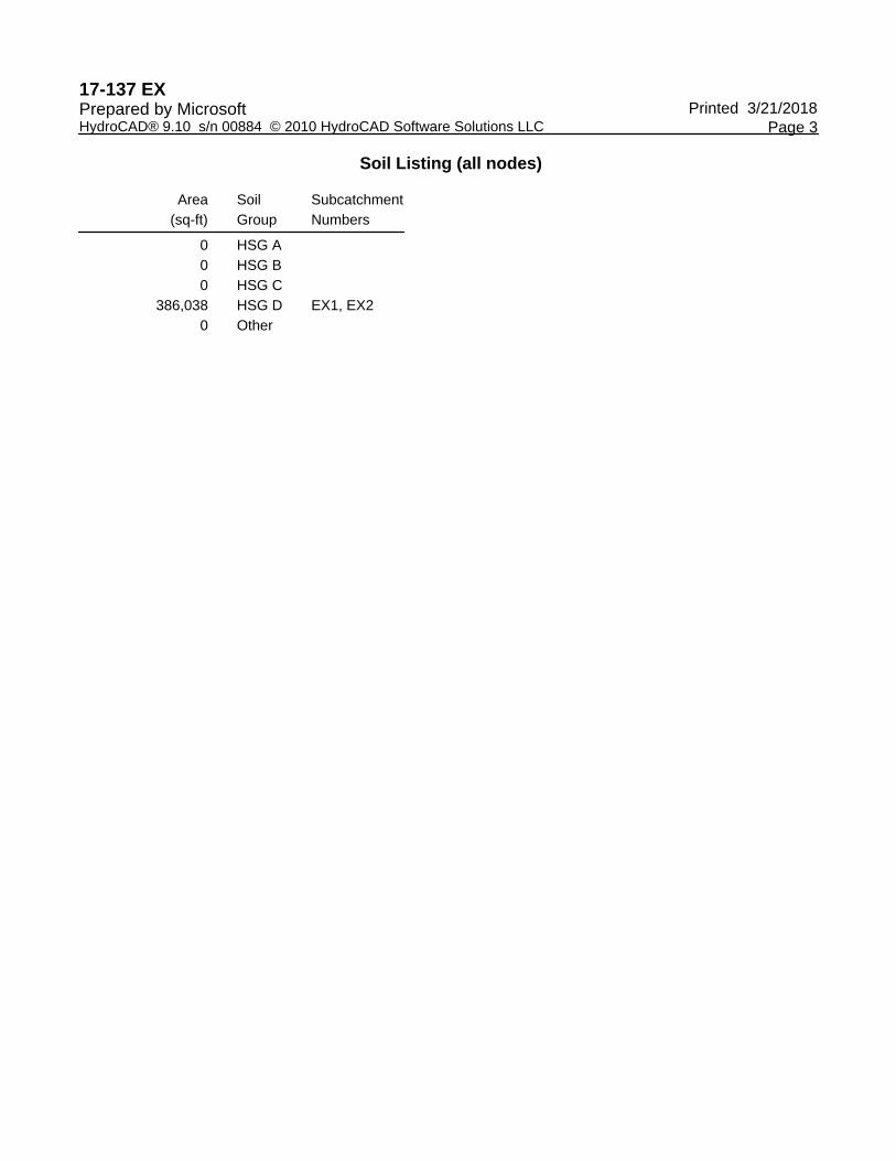
Soil Listing (all nodes)
Area(sq-ft)
SoilGroup
SubcatchmentNumbers
0 HSG A0 HSG B0 HSG C
386,038 HSG D EX1, EX20 Other

Type III 24-hr 2 YR, 24 HR Rainfall=3.10"17-137 EX Printed 3/21/2018Prepared by Microsoft
Page 4HydroCAD® 9.10 s/n 00884 © 2010 HydroCAD Software Solutions LLC
Summary for Subcatchment EX1: Watershed 1A
Runoff = 12.27 cfs @ 12.33 hrs, Volume= 63,769 cf, Depth= 2.35"
Runoff by SCS TR-20 method, UH=SCS, Time Span= 0.00-72.00 hrs, dt= 0.01 hrsType III 24-hr 2 YR, 24 HR Rainfall=3.10"
Area (sf) CN Description94,141 80 >75% Grass cover, Good, HSG D97,266 98 Roofs, HSG D89,163 98 Paved parking, HSG D
* 45,085 98 Bordering Vegitaed Wetland, HSG D325,655 93 Weighted Average
94,141 28.91% Pervious Area231,514 71.09% Impervious Area
Tc Length Slope Velocity Capacity Description(min) (feet) (ft/ft) (ft/sec) (cfs)
5.4 50 0.0600 0.16 Sheet Flow, lawnGrass: Dense n= 0.240 P2= 3.10"
1.3 110 0.0400 1.40 Shallow Concentrated Flow, lawnShort Grass Pasture Kv= 7.0 fps
2.4 292 0.0100 2.03 Shallow Concentrated Flow, parking lotPaved Kv= 20.3 fps
16.3 463 0.0010 0.47 Shallow Concentrated Flow, swalesGrassed Waterway Kv= 15.0 fps
25.4 915 Total
Summary for Subcatchment EX2: Watershed 1B
Runoff = 1.80 cfs @ 12.16 hrs, Volume= 6,670 cf, Depth= 1.33"
Runoff by SCS TR-20 method, UH=SCS, Time Span= 0.00-72.00 hrs, dt= 0.01 hrsType III 24-hr 2 YR, 24 HR Rainfall=3.10"
Area (sf) CN Description60,383 80 >75% Grass cover, Good, HSG D60,383 100.00% Pervious Area
Tc Length Slope Velocity Capacity Description(min) (feet) (ft/ft) (ft/sec) (cfs)
9.5 50 0.0400 0.09 Sheet Flow, Woods: Light underbrush n= 0.400 P2= 3.10"
1.5 162 0.0670 1.81 Shallow Concentrated Flow, Short Grass Pasture Kv= 7.0 fps
11.0 212 Total
Type III 24-hr 10 YR, 24 HR Rainfall=4.70"17-137 EX Printed 3/21/2018Prepared by Microsoft
Page 5HydroCAD® 9.10 s/n 00884 © 2010 HydroCAD Software Solutions LLC
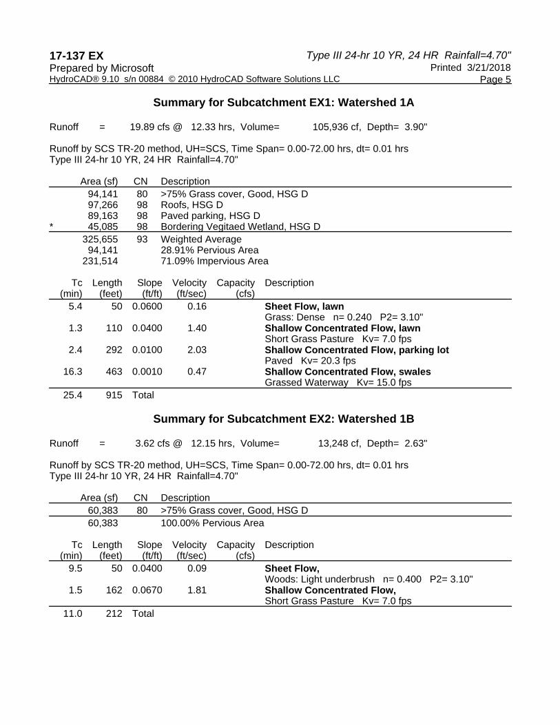
Summary for Subcatchment EX1: Watershed 1A
Runoff = 19.89 cfs @ 12.33 hrs, Volume= 105,936 cf, Depth= 3.90"
Runoff by SCS TR-20 method, UH=SCS, Time Span= 0.00-72.00 hrs, dt= 0.01 hrsType III 24-hr 10 YR, 24 HR Rainfall=4.70"
Area (sf) CN Description94,141 80 >75% Grass cover, Good, HSG D97,266 98 Roofs, HSG D89,163 98 Paved parking, HSG D
* 45,085 98 Bordering Vegitaed Wetland, HSG D325,655 93 Weighted Average
94,141 28.91% Pervious Area231,514 71.09% Impervious Area
Tc Length Slope Velocity Capacity Description(min) (feet) (ft/ft) (ft/sec) (cfs)
5.4 50 0.0600 0.16 Sheet Flow, lawnGrass: Dense n= 0.240 P2= 3.10"
1.3 110 0.0400 1.40 Shallow Concentrated Flow, lawnShort Grass Pasture Kv= 7.0 fps
2.4 292 0.0100 2.03 Shallow Concentrated Flow, parking lotPaved Kv= 20.3 fps
16.3 463 0.0010 0.47 Shallow Concentrated Flow, swalesGrassed Waterway Kv= 15.0 fps
25.4 915 Total
Summary for Subcatchment EX2: Watershed 1B
Runoff = 3.62 cfs @ 12.15 hrs, Volume= 13,248 cf, Depth= 2.63"
Runoff by SCS TR-20 method, UH=SCS, Time Span= 0.00-72.00 hrs, dt= 0.01 hrsType III 24-hr 10 YR, 24 HR Rainfall=4.70"
Area (sf) CN Description60,383 80 >75% Grass cover, Good, HSG D60,383 100.00% Pervious Area
Tc Length Slope Velocity Capacity Description(min) (feet) (ft/ft) (ft/sec) (cfs)
9.5 50 0.0400 0.09 Sheet Flow, Woods: Light underbrush n= 0.400 P2= 3.10"
1.5 162 0.0670 1.81 Shallow Concentrated Flow, Short Grass Pasture Kv= 7.0 fps
11.0 212 Total

Type III 24-hr 100 YR, 24 HR Rainfall=8.30"17-137 EX Printed 3/21/2018Prepared by Microsoft
Page 6HydroCAD® 9.10 s/n 00884 © 2010 HydroCAD Software Solutions LLC
Summary for Subcatchment EX1: Watershed 1A
Runoff = 36.75 cfs @ 12.33 hrs, Volume= 202,460 cf, Depth= 7.46"
Runoff by SCS TR-20 method, UH=SCS, Time Span= 0.00-72.00 hrs, dt= 0.01 hrsType III 24-hr 100 YR, 24 HR Rainfall=8.30"
Area (sf) CN Description94,141 80 >75% Grass cover, Good, HSG D97,266 98 Roofs, HSG D89,163 98 Paved parking, HSG D
* 45,085 98 Bordering Vegitaed Wetland, HSG D325,655 93 Weighted Average
94,141 28.91% Pervious Area231,514 71.09% Impervious Area
Tc Length Slope Velocity Capacity Description(min) (feet) (ft/ft) (ft/sec) (cfs)
5.4 50 0.0600 0.16 Sheet Flow, lawnGrass: Dense n= 0.240 P2= 3.10"
1.3 110 0.0400 1.40 Shallow Concentrated Flow, lawnShort Grass Pasture Kv= 7.0 fps
2.4 292 0.0100 2.03 Shallow Concentrated Flow, parking lotPaved Kv= 20.3 fps
16.3 463 0.0010 0.47 Shallow Concentrated Flow, swalesGrassed Waterway Kv= 15.0 fps
25.4 915 Total
Summary for Subcatchment EX2: Watershed 1B
Runoff = 8.00 cfs @ 12.15 hrs, Volume= 29,723 cf, Depth= 5.91"
Runoff by SCS TR-20 method, UH=SCS, Time Span= 0.00-72.00 hrs, dt= 0.01 hrsType III 24-hr 100 YR, 24 HR Rainfall=8.30"
Area (sf) CN Description60,383 80 >75% Grass cover, Good, HSG D60,383 100.00% Pervious Area
Tc Length Slope Velocity Capacity Description(min) (feet) (ft/ft) (ft/sec) (cfs)
9.5 50 0.0400 0.09 Sheet Flow, Woods: Light underbrush n= 0.400 P2= 3.10"
1.5 162 0.0670 1.81 Shallow Concentrated Flow, Short Grass Pasture Kv= 7.0 fps
11.0 212 Total
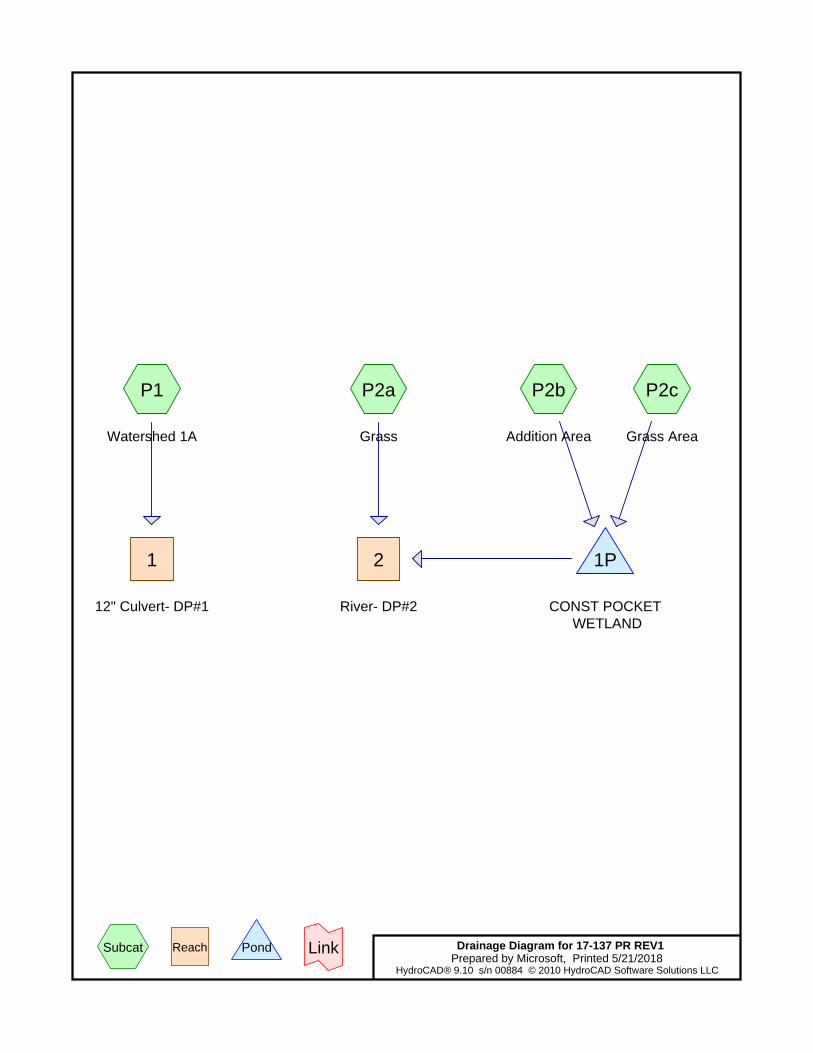
P1
Watershed 1A
P2a
Grass
P2b
Addition Area
P2c
Grass Area
1
12" Culvert- DP#1
2
River- DP#2
1P
CONST POCKET WETLAND
Drainage Diagram for 17-137 PR REV1Prepared by Microsoft, Printed 5/21/2018
HydroCAD® 9.10 s/n 00884 © 2010 HydroCAD Software Solutions LLC
Subcat Reach Pond Link

17-137 PR REV1 Printed 5/21/2018Prepared by Microsoft
Page 2HydroCAD® 9.10 s/n 00884 © 2010 HydroCAD Software Solutions LLC
Area Listing (all nodes)
Area(sq-ft)
CN Description(subcatchment-numbers)
115,333 80 >75% Grass cover, Good, HSG D (P1, P2a, P2c)45,085 98 Bordering Vegitaed Wetland, HSG D (P1)87,243 98 Paved parking, HSG D (P1, P2b)
138,377 98 Roofs, HSG D (P1, P2b)
17-137 PR REV1 Printed 5/21/2018Prepared by Microsoft
Page 3HydroCAD® 9.10 s/n 00884 © 2010 HydroCAD Software Solutions LLC
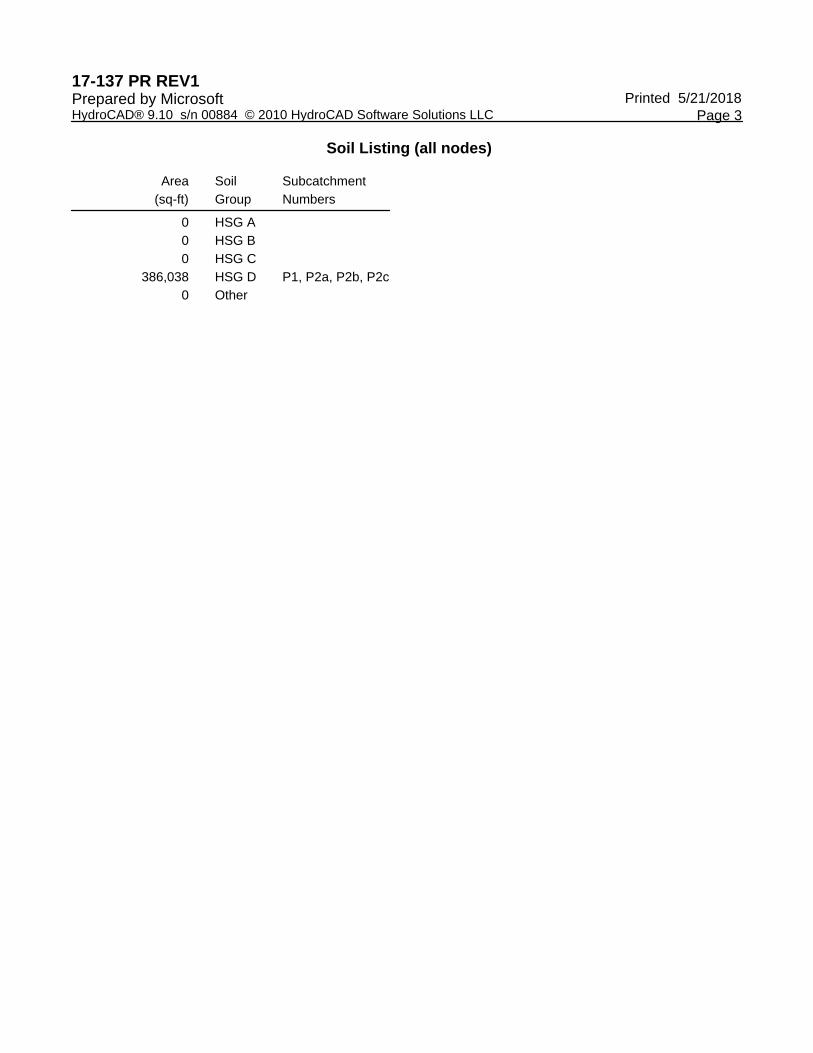
Soil Listing (all nodes)
Area(sq-ft)
SoilGroup
SubcatchmentNumbers
0 HSG A0 HSG B0 HSG C
386,038 HSG D P1, P2a, P2b, P2c0 Other

Type III 24-hr 2 YR, 24 HR Rainfall=3.10"17-137 PR REV1 Printed 5/21/2018Prepared by Microsoft
Page 4HydroCAD® 9.10 s/n 00884 © 2010 HydroCAD Software Solutions LLC
Summary for Subcatchment P1: Watershed 1A
Runoff = 12.25 cfs @ 12.27 hrs, Volume= 59,018 cf, Depth= 2.45"
Runoff by SCS TR-20 method, UH=SCS, Time Span= 0.00-72.00 hrs, dt= 0.01 hrsType III 24-hr 2 YR, 24 HR Rainfall=3.10"
Area (sf) CN Description62,344 80 >75% Grass cover, Good, HSG D97,266 98 Roofs, HSG D84,743 98 Paved parking, HSG D
* 45,085 98 Bordering Vegitaed Wetland, HSG D289,438 94 Weighted Average
62,344 21.54% Pervious Area227,094 78.46% Impervious Area
Tc Length Slope Velocity Capacity Description(min) (feet) (ft/ft) (ft/sec) (cfs)
1.1 50 0.0070 0.77 Sheet Flow, Smooth surfaces n= 0.011 P2= 3.10"
2.8 337 0.0100 2.03 Shallow Concentrated Flow, Paved Kv= 20.3 fps
16.8 478 0.0010 0.47 Shallow Concentrated Flow, Grassed Waterway Kv= 15.0 fps
20.7 865 Total
Summary for Subcatchment P2a: Grass
Runoff = 1.03 cfs @ 12.28 hrs, Volume= 4,745 cf, Depth= 1.33"
Runoff by SCS TR-20 method, UH=SCS, Time Span= 0.00-72.00 hrs, dt= 0.01 hrsType III 24-hr 2 YR, 24 HR Rainfall=3.10"
Area (sf) CN Description42,957 80 >75% Grass cover, Good, HSG D42,957 100.00% Pervious Area
Tc Length Slope Velocity Capacity Description(min) (feet) (ft/ft) (ft/sec) (cfs)17.8 50 0.0030 0.05 Sheet Flow,
Grass: Dense n= 0.240 P2= 3.10"1.7 142 0.0400 1.40 Shallow Concentrated Flow,
Short Grass Pasture Kv= 7.0 fps19.5 192 Total
Type III 24-hr 2 YR, 24 HR Rainfall=3.10"17-137 PR REV1 Printed 5/21/2018Prepared by Microsoft
Page 5HydroCAD® 9.10 s/n 00884 © 2010 HydroCAD Software Solutions LLC
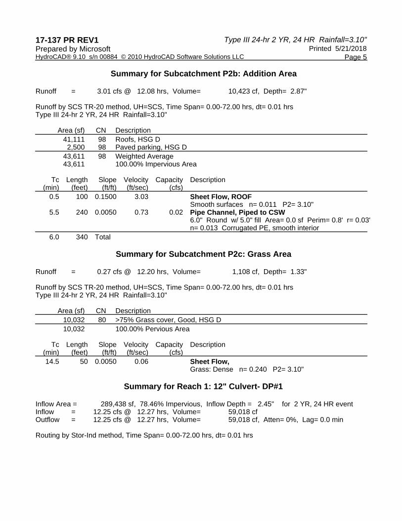
Summary for Subcatchment P2b: Addition Area
Runoff = 3.01 cfs @ 12.08 hrs, Volume= 10,423 cf, Depth= 2.87"
Runoff by SCS TR-20 method, UH=SCS, Time Span= 0.00-72.00 hrs, dt= 0.01 hrsType III 24-hr 2 YR, 24 HR Rainfall=3.10"
Area (sf) CN Description41,111 98 Roofs, HSG D
2,500 98 Paved parking, HSG D43,611 98 Weighted Average43,611 100.00% Impervious Area
Tc Length Slope Velocity Capacity Description(min) (feet) (ft/ft) (ft/sec) (cfs)
0.5 100 0.1500 3.03 Sheet Flow, ROOFSmooth surfaces n= 0.011 P2= 3.10"
5.5 240 0.0050 0.73 0.02 Pipe Channel, Piped to CSW6.0" Round w/ 5.0" fill Area= 0.0 sf Perim= 0.8' r= 0.03'n= 0.013 Corrugated PE, smooth interior
6.0 340 Total
Summary for Subcatchment P2c: Grass Area
Runoff = 0.27 cfs @ 12.20 hrs, Volume= 1,108 cf, Depth= 1.33"
Runoff by SCS TR-20 method, UH=SCS, Time Span= 0.00-72.00 hrs, dt= 0.01 hrsType III 24-hr 2 YR, 24 HR Rainfall=3.10"
Area (sf) CN Description10,032 80 >75% Grass cover, Good, HSG D10,032 100.00% Pervious Area
Tc Length Slope Velocity Capacity Description(min) (feet) (ft/ft) (ft/sec) (cfs)14.5 50 0.0050 0.06 Sheet Flow,
Grass: Dense n= 0.240 P2= 3.10"
Summary for Reach 1: 12" Culvert- DP#1
Inflow Area = 289,438 sf, 78.46% Impervious, Inflow Depth = 2.45" for 2 YR, 24 HR eventInflow = 12.25 cfs @ 12.27 hrs, Volume= 59,018 cfOutflow = 12.25 cfs @ 12.27 hrs, Volume= 59,018 cf, Atten= 0%, Lag= 0.0 min
Routing by Stor-Ind method, Time Span= 0.00-72.00 hrs, dt= 0.01 hrs

Type III 24-hr 2 YR, 24 HR Rainfall=3.10"17-137 PR REV1 Printed 5/21/2018Prepared by Microsoft
Page 6HydroCAD® 9.10 s/n 00884 © 2010 HydroCAD Software Solutions LLC
Summary for Reach 2: River- DP#2
Inflow Area = 96,600 sf, 45.15% Impervious, Inflow Depth = 2.02" for 2 YR, 24 HR eventInflow = 1.68 cfs @ 12.29 hrs, Volume= 16,276 cfOutflow = 1.68 cfs @ 12.29 hrs, Volume= 16,276 cf, Atten= 0%, Lag= 0.0 min
Routing by Stor-Ind method, Time Span= 0.00-72.00 hrs, dt= 0.01 hrs
Summary for Pond 1P: CONST POCKET WETLAND
Inflow Area = 53,643 sf, 81.30% Impervious, Inflow Depth = 2.58" for 2 YR, 24 HR eventInflow = 3.18 cfs @ 12.09 hrs, Volume= 11,531 cfOutflow = 0.71 cfs @ 12.52 hrs, Volume= 11,531 cf, Atten= 78%, Lag= 25.9 minPrimary = 0.71 cfs @ 12.52 hrs, Volume= 11,531 cf
Routing by Stor-Ind method, Time Span= 0.00-72.00 hrs, dt= 0.01 hrsPeak Elev= 13.40' @ 12.52 hrs Surf.Area= 2,583 sf Storage= 3,455 cfFlood Elev= 15.30' Surf.Area= 4,569 sf Storage= 10,190 cf
Plug-Flow detention time= 46.0 min calculated for 11,529 cf (100% of inflow)Center-of-Mass det. time= 46.0 min ( 812.2 - 766.2 )
Volume Invert Avail.Storage Storage Description#1 11.25' 13,663 cf Custom Stage Data (Prismatic) Listed below (Recalc)
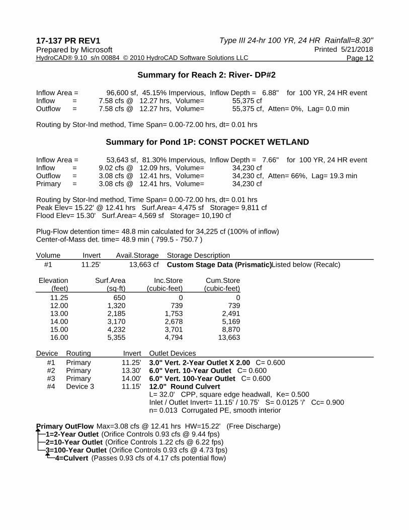
Elevation Surf.Area Inc.Store Cum.Store(feet) (sq-ft) (cubic-feet) (cubic-feet)11.25 650 0 012.00 1,320 739 73913.00 2,185 1,753 2,49114.00 3,170 2,678 5,16915.00 4,232 3,701 8,87016.00 5,355 4,794 13,663
Device Routing Invert Outlet Devices#1 Primary 11.25' 3.0" Vert. 2-Year Outlet X 2.00 C= 0.600 #2 Primary 13.30' 6.0" Vert. 10-Year Outlet C= 0.600 #3 Primary 14.00' 6.0" Vert. 100-Year Outlet C= 0.600 #4 Device 3 11.15' 12.0" Round Culvert
L= 32.0' CPP, square edge headwall, Ke= 0.500 Inlet / Outlet Invert= 11.15' / 10.75' S= 0.0125 '/' Cc= 0.900 n= 0.013 Corrugated PE, smooth interior
Primary OutFlow Max=0.71 cfs @ 12.52 hrs HW=13.40' (Free Discharge)1=2-Year Outlet (Orifice Controls 0.67 cfs @ 6.86 fps)2=10-Year Outlet (Orifice Controls 0.03 cfs @ 1.10 fps)3=100-Year Outlet ( Controls 0.00 cfs)
4=Culvert ( Controls 0.00 cfs)

Type III 24-hr 10 YR, 24 HR Rainfall=4.70"17-137 PR REV1 Printed 5/21/2018Prepared by Microsoft
Page 7HydroCAD® 9.10 s/n 00884 © 2010 HydroCAD Software Solutions LLC
Summary for Subcatchment P1: Watershed 1A
Runoff = 19.60 cfs @ 12.26 hrs, Volume= 96,774 cf, Depth= 4.01"
Runoff by SCS TR-20 method, UH=SCS, Time Span= 0.00-72.00 hrs, dt= 0.01 hrsType III 24-hr 10 YR, 24 HR Rainfall=4.70"
Area (sf) CN Description62,344 80 >75% Grass cover, Good, HSG D97,266 98 Roofs, HSG D84,743 98 Paved parking, HSG D
* 45,085 98 Bordering Vegitaed Wetland, HSG D289,438 94 Weighted Average
62,344 21.54% Pervious Area227,094 78.46% Impervious Area
Tc Length Slope Velocity Capacity Description(min) (feet) (ft/ft) (ft/sec) (cfs)
1.1 50 0.0070 0.77 Sheet Flow, Smooth surfaces n= 0.011 P2= 3.10"
2.8 337 0.0100 2.03 Shallow Concentrated Flow, Paved Kv= 20.3 fps
16.8 478 0.0010 0.47 Shallow Concentrated Flow, Grassed Waterway Kv= 15.0 fps
20.7 865 Total
Summary for Subcatchment P2a: Grass
Runoff = 2.07 cfs @ 12.27 hrs, Volume= 9,425 cf, Depth= 2.63"
Runoff by SCS TR-20 method, UH=SCS, Time Span= 0.00-72.00 hrs, dt= 0.01 hrsType III 24-hr 10 YR, 24 HR Rainfall=4.70"
Area (sf) CN Description42,957 80 >75% Grass cover, Good, HSG D42,957 100.00% Pervious Area
Tc Length Slope Velocity Capacity Description(min) (feet) (ft/ft) (ft/sec) (cfs)17.8 50 0.0030 0.05 Sheet Flow,
Grass: Dense n= 0.240 P2= 3.10"1.7 142 0.0400 1.40 Shallow Concentrated Flow,
Short Grass Pasture Kv= 7.0 fps19.5 192 Total

Type III 24-hr 10 YR, 24 HR Rainfall=4.70"17-137 PR REV1 Printed 5/21/2018Prepared by Microsoft
Page 8HydroCAD® 9.10 s/n 00884 © 2010 HydroCAD Software Solutions LLC
Summary for Subcatchment P2b: Addition Area
Runoff = 4.60 cfs @ 12.08 hrs, Volume= 16,222 cf, Depth= 4.46"
Runoff by SCS TR-20 method, UH=SCS, Time Span= 0.00-72.00 hrs, dt= 0.01 hrsType III 24-hr 10 YR, 24 HR Rainfall=4.70"
Area (sf) CN Description41,111 98 Roofs, HSG D
2,500 98 Paved parking, HSG D43,611 98 Weighted Average43,611 100.00% Impervious Area
Tc Length Slope Velocity Capacity Description(min) (feet) (ft/ft) (ft/sec) (cfs)
0.5 100 0.1500 3.03 Sheet Flow, ROOFSmooth surfaces n= 0.011 P2= 3.10"
5.5 240 0.0050 0.73 0.02 Pipe Channel, Piped to CSW6.0" Round w/ 5.0" fill Area= 0.0 sf Perim= 0.8' r= 0.03'n= 0.013 Corrugated PE, smooth interior
6.0 340 Total
Summary for Subcatchment P2c: Grass Area
Runoff = 0.55 cfs @ 12.20 hrs, Volume= 2,201 cf, Depth= 2.63"
Runoff by SCS TR-20 method, UH=SCS, Time Span= 0.00-72.00 hrs, dt= 0.01 hrsType III 24-hr 10 YR, 24 HR Rainfall=4.70"
Area (sf) CN Description10,032 80 >75% Grass cover, Good, HSG D10,032 100.00% Pervious Area
Tc Length Slope Velocity Capacity Description(min) (feet) (ft/ft) (ft/sec) (cfs)14.5 50 0.0050 0.06 Sheet Flow,
Grass: Dense n= 0.240 P2= 3.10"
Summary for Reach 1: 12" Culvert- DP#1
Inflow Area = 289,438 sf, 78.46% Impervious, Inflow Depth = 4.01" for 10 YR, 24 HR eventInflow = 19.60 cfs @ 12.26 hrs, Volume= 96,774 cfOutflow = 19.60 cfs @ 12.26 hrs, Volume= 96,774 cf, Atten= 0%, Lag= 0.0 min
Routing by Stor-Ind method, Time Span= 0.00-72.00 hrs, dt= 0.01 hrs

Type III 24-hr 10 YR, 24 HR Rainfall=4.70"17-137 PR REV1 Printed 5/21/2018Prepared by Microsoft
Page 9HydroCAD® 9.10 s/n 00884 © 2010 HydroCAD Software Solutions LLC
Summary for Reach 2: River- DP#2
Inflow Area = 96,600 sf, 45.15% Impervious, Inflow Depth = 3.46" for 10 YR, 24 HR eventInflow = 3.46 cfs @ 12.29 hrs, Volume= 27,848 cfOutflow = 3.46 cfs @ 12.29 hrs, Volume= 27,848 cf, Atten= 0%, Lag= 0.0 min
Routing by Stor-Ind method, Time Span= 0.00-72.00 hrs, dt= 0.01 hrs
Summary for Pond 1P: CONST POCKET WETLAND
Inflow Area = 53,643 sf, 81.30% Impervious, Inflow Depth = 4.12" for 10 YR, 24 HR eventInflow = 4.97 cfs @ 12.09 hrs, Volume= 18,423 cfOutflow = 1.47 cfs @ 12.45 hrs, Volume= 18,423 cf, Atten= 70%, Lag= 21.7 minPrimary = 1.47 cfs @ 12.45 hrs, Volume= 18,423 cf
Routing by Stor-Ind method, Time Span= 0.00-72.00 hrs, dt= 0.01 hrsPeak Elev= 14.07' @ 12.45 hrs Surf.Area= 3,244 sf Storage= 5,394 cfFlood Elev= 15.30' Surf.Area= 4,569 sf Storage= 10,190 cf
Plug-Flow detention time= 48.2 min calculated for 18,421 cf (100% of inflow)Center-of-Mass det. time= 48.2 min ( 807.2 - 759.0 )
Volume Invert Avail.Storage Storage Description#1 11.25' 13,663 cf Custom Stage Data (Prismatic) Listed below (Recalc)
Elevation Surf.Area Inc.Store Cum.Store(feet) (sq-ft) (cubic-feet) (cubic-feet)11.25 650 0 012.00 1,320 739 73913.00 2,185 1,753 2,49114.00 3,170 2,678 5,16915.00 4,232 3,701 8,87016.00 5,355 4,794 13,663
Device Routing Invert Outlet Devices#1 Primary 11.25' 3.0" Vert. 2-Year Outlet X 2.00 C= 0.600 #2 Primary 13.30' 6.0" Vert. 10-Year Outlet C= 0.600 #3 Primary 14.00' 6.0" Vert. 100-Year Outlet C= 0.600 #4 Device 3 11.15' 12.0" Round Culvert
L= 32.0' CPP, square edge headwall, Ke= 0.500 Inlet / Outlet Invert= 11.15' / 10.75' S= 0.0125 '/' Cc= 0.900 n= 0.013 Corrugated PE, smooth interior
Primary OutFlow Max=1.47 cfs @ 12.45 hrs HW=14.07' (Free Discharge)1=2-Year Outlet (Orifice Controls 0.78 cfs @ 7.90 fps)2=10-Year Outlet (Orifice Controls 0.68 cfs @ 3.47 fps)3=100-Year Outlet (Orifice Controls 0.02 cfs @ 0.90 fps)
4=Culvert (Passes 0.02 cfs of 1.00 cfs potential flow)

Type III 24-hr 100 YR, 24 HR Rainfall=8.30"17-137 PR REV1 Printed 5/21/2018Prepared by Microsoft
Page 10HydroCAD® 9.10 s/n 00884 © 2010 HydroCAD Software Solutions LLC
Summary for Subcatchment P1: Watershed 1A
Runoff = 35.84 cfs @ 12.26 hrs, Volume= 182,835 cf, Depth= 7.58"
Runoff by SCS TR-20 method, UH=SCS, Time Span= 0.00-72.00 hrs, dt= 0.01 hrsType III 24-hr 100 YR, 24 HR Rainfall=8.30"
Area (sf) CN Description62,344 80 >75% Grass cover, Good, HSG D97,266 98 Roofs, HSG D84,743 98 Paved parking, HSG D
* 45,085 98 Bordering Vegitaed Wetland, HSG D289,438 94 Weighted Average
62,344 21.54% Pervious Area227,094 78.46% Impervious Area
Tc Length Slope Velocity Capacity Description(min) (feet) (ft/ft) (ft/sec) (cfs)
1.1 50 0.0070 0.77 Sheet Flow, Smooth surfaces n= 0.011 P2= 3.10"
2.8 337 0.0100 2.03 Shallow Concentrated Flow, Paved Kv= 20.3 fps
16.8 478 0.0010 0.47 Shallow Concentrated Flow, Grassed Waterway Kv= 15.0 fps
20.7 865 Total
Summary for Subcatchment P2a: Grass
Runoff = 4.59 cfs @ 12.26 hrs, Volume= 21,145 cf, Depth= 5.91"
Runoff by SCS TR-20 method, UH=SCS, Time Span= 0.00-72.00 hrs, dt= 0.01 hrsType III 24-hr 100 YR, 24 HR Rainfall=8.30"
Area (sf) CN Description42,957 80 >75% Grass cover, Good, HSG D42,957 100.00% Pervious Area
Tc Length Slope Velocity Capacity Description(min) (feet) (ft/ft) (ft/sec) (cfs)17.8 50 0.0030 0.05 Sheet Flow,
Grass: Dense n= 0.240 P2= 3.10"1.7 142 0.0400 1.40 Shallow Concentrated Flow,
Short Grass Pasture Kv= 7.0 fps19.5 192 Total

Type III 24-hr 100 YR, 24 HR Rainfall=8.30"17-137 PR REV1 Printed 5/21/2018Prepared by Microsoft
Page 11HydroCAD® 9.10 s/n 00884 © 2010 HydroCAD Software Solutions LLC
Summary for Subcatchment P2b: Addition Area
Runoff = 8.16 cfs @ 12.08 hrs, Volume= 29,292 cf, Depth= 8.06"
Runoff by SCS TR-20 method, UH=SCS, Time Span= 0.00-72.00 hrs, dt= 0.01 hrsType III 24-hr 100 YR, 24 HR Rainfall=8.30"
Area (sf) CN Description41,111 98 Roofs, HSG D
2,500 98 Paved parking, HSG D43,611 98 Weighted Average43,611 100.00% Impervious Area
Tc Length Slope Velocity Capacity Description(min) (feet) (ft/ft) (ft/sec) (cfs)
0.5 100 0.1500 3.03 Sheet Flow, ROOFSmooth surfaces n= 0.011 P2= 3.10"
5.5 240 0.0050 0.73 0.02 Pipe Channel, Piped to CSW6.0" Round w/ 5.0" fill Area= 0.0 sf Perim= 0.8' r= 0.03'n= 0.013 Corrugated PE, smooth interior
6.0 340 Total
Summary for Subcatchment P2c: Grass Area
Runoff = 1.21 cfs @ 12.20 hrs, Volume= 4,938 cf, Depth= 5.91"
Runoff by SCS TR-20 method, UH=SCS, Time Span= 0.00-72.00 hrs, dt= 0.01 hrsType III 24-hr 100 YR, 24 HR Rainfall=8.30"
Area (sf) CN Description10,032 80 >75% Grass cover, Good, HSG D10,032 100.00% Pervious Area
Tc Length Slope Velocity Capacity Description(min) (feet) (ft/ft) (ft/sec) (cfs)14.5 50 0.0050 0.06 Sheet Flow,
Grass: Dense n= 0.240 P2= 3.10"
Summary for Reach 1: 12" Culvert- DP#1
Inflow Area = 289,438 sf, 78.46% Impervious, Inflow Depth = 7.58" for 100 YR, 24 HR eventInflow = 35.84 cfs @ 12.26 hrs, Volume= 182,835 cfOutflow = 35.84 cfs @ 12.26 hrs, Volume= 182,835 cf, Atten= 0%, Lag= 0.0 min
Routing by Stor-Ind method, Time Span= 0.00-72.00 hrs, dt= 0.01 hrs
Type III 24-hr 100 YR, 24 HR Rainfall=8.30"17-137 PR REV1 Printed 5/21/2018Prepared by Microsoft
Page 12HydroCAD® 9.10 s/n 00884 © 2010 HydroCAD Software Solutions LLC
Summary for Reach 2: River- DP#2
Inflow Area = 96,600 sf, 45.15% Impervious, Inflow Depth = 6.88" for 100 YR, 24 HR eventInflow = 7.58 cfs @ 12.27 hrs, Volume= 55,375 cfOutflow = 7.58 cfs @ 12.27 hrs, Volume= 55,375 cf, Atten= 0%, Lag= 0.0 min
Routing by Stor-Ind method, Time Span= 0.00-72.00 hrs, dt= 0.01 hrs
Summary for Pond 1P: CONST POCKET WETLAND
Inflow Area = 53,643 sf, 81.30% Impervious, Inflow Depth = 7.66" for 100 YR, 24 HR eventInflow = 9.02 cfs @ 12.09 hrs, Volume= 34,230 cfOutflow = 3.08 cfs @ 12.41 hrs, Volume= 34,230 cf, Atten= 66%, Lag= 19.3 minPrimary = 3.08 cfs @ 12.41 hrs, Volume= 34,230 cf
Routing by Stor-Ind method, Time Span= 0.00-72.00 hrs, dt= 0.01 hrsPeak Elev= 15.22' @ 12.41 hrs Surf.Area= 4,475 sf Storage= 9,811 cfFlood Elev= 15.30' Surf.Area= 4,569 sf Storage= 10,190 cf
Plug-Flow detention time= 48.8 min calculated for 34,225 cf (100% of inflow)Center-of-Mass det. time= 48.9 min ( 799.5 - 750.7 )
Volume Invert Avail.Storage Storage Description#1 11.25' 13,663 cf Custom Stage Data (Prismatic) Listed below (Recalc)
Elevation Surf.Area Inc.Store Cum.Store(feet) (sq-ft) (cubic-feet) (cubic-feet)11.25 650 0 012.00 1,320 739 73913.00 2,185 1,753 2,49114.00 3,170 2,678 5,16915.00 4,232 3,701 8,87016.00 5,355 4,794 13,663
Device Routing Invert Outlet Devices#1 Primary 11.25' 3.0" Vert. 2-Year Outlet X 2.00 C= 0.600 #2 Primary 13.30' 6.0" Vert. 10-Year Outlet C= 0.600 #3 Primary 14.00' 6.0" Vert. 100-Year Outlet C= 0.600 #4 Device 3 11.15' 12.0" Round Culvert
L= 32.0' CPP, square edge headwall, Ke= 0.500 Inlet / Outlet Invert= 11.15' / 10.75' S= 0.0125 '/' Cc= 0.900 n= 0.013 Corrugated PE, smooth interior
Primary OutFlow Max=3.08 cfs @ 12.41 hrs HW=15.22' (Free Discharge)1=2-Year Outlet (Orifice Controls 0.93 cfs @ 9.44 fps)2=10-Year Outlet (Orifice Controls 1.22 cfs @ 6.22 fps)3=100-Year Outlet (Orifice Controls 0.93 cfs @ 4.73 fps)
4=Culvert (Passes 0.93 cfs of 4.17 cfs potential flow)

3 Perkins Way
Appendix C
Operation & Maintenance Plan

STORMWATER MANAGEMENT OPERATION AND MAINTENANCE PLAN
3 Perkins Way
Newburyport, Massachusetts The following Stormwater Management Operation and Maintenance (O&M) Plan has been prepared to operate and maintain the stormwater management system for the proposed 3 Perkins Way Drainage Systems. Owner/Operator: Bradford & Bigelow #3 Perkins Way Inspection and Maintenance Schedule Personnel entrusted by the owner/operator with stormwater maintenance shall inspect the stormwater management system on a routine basis not less than once per month for the first 6 months of operation and semi-annually thereafter. Refer to the Design Plans for stormwater measure information. Inspection and maintenance shall be performed as follows:
1. Landscaped Areas shall be inspected and maintained on a monthly basis. Areas which may be subject to erosion will be stabilized and reseeded immediately. These operations will be performed as part of ongoing routine grounds maintenance operations, and shall be the responsibility of the Homeowners Association.
2. Street Sweeping of drives and parking areas shall be conducted bimonthly between the months of April and November. Removed sediment will be disposed off site by a qualified waste disposal contractor in accordance with state and federal regulations.
3. Rain Garden : Vegetation shall be inspected monthly for disease or pest problems. If
treatment is warranted, a non-toxic approach is the only allowed method. Promptly replace any vegetation that is beyond treatment. During times of extended drought, inspect vegetation for signs of stress including wilting or spotted or brown leaves. Water as required. Bioretention areas shall be weeded at least twice a year as required.
Inspect soil and repair eroded areas monthly. Re-plant void areas as needed. Remove litter and debris monthly. Remove and replace dead vegetation twice per year in spring and fall. Replace soil media if ponding is witnessed more than 48 hours after rainfall event, and remove any accumulated sediments. The Engineered Soil Mix for Bioretention Systems Designed to Exfiltrate should consist of the following mixture:
-40% sand -20-30% topsoil -30-40% compost - Percentage of standing water that is unvegetated (excluding the deep water cells) - The maximum elevation and the vegetative condition in this zone - Stability of the original depth zones and the micro-topographic features - Accumulation of sediment in the forebay and micropool; and survival rate of plants
(cells with dead plants must be replanted)
4. Pocket Wetland: In the first three years after construction, inspect the wetland twice a year during both the growing and non-growing seasons. During these inspections, record and map the following information: - The types and distribution of the dominant wetland plants - The presence and distribution of planted wetland species - The presence and distribution of invasive wetland species (must be removed) - Indications that other species are replacing the planted wetland species - Percentage of standing water that is unvegetated (excluding the deep water cells) - The maximum elevation and the vegetative condition in this zone - Stability of the original depth zones and the micro-topographic features - Accumulation of sediment in the forebay and micropool; and survival rate of plants
(cells with dead plants must be replanted)
4. Particle Separator – See attached maintenance procedures for Stormceptor proprietary particle separators. All sediments removed must be disposed of in accordance with all applicable local and state regulations.

Stormwater System Inspection Report
General Information
Location: 3 Perkins Way, Newburyport
Date of Inspection Start/End Time
Inspector’s Name(s)
Inspector’s Title(s)
Inspector’s Contact Information
Purpose of Inspection
Weather Information
Has it rained since the last inspection? Yes No Weather at time of this inspection?
Site-Specific Stormwater Devices
Description
Installed and Operating Properly? Corrective Action Needed
Date for Corrective Action/Responsible Person
1 Yes No
2 Yes No
3 Yes No
4 Yes No
5 Yes No
6 Yes No
7 Yes No
8 Yes No
9 Yes No

Description
Installed and Operating Properly? Corrective Action Needed
Date for Corrective Action/Responsible Person
11 Yes No
12 Yes No
13 Yes No
14 Yes No
15 Yes No
16 Yes No
17 Yes No
18 Yes No
19 Yes No
20 Yes No
21 Yes No
22 Yes No
23 Yes No
24 Yes No
25 Yes No
26 Yes No
27 Yes No
28 Yes No
29 Yes No

Overall Site Issues
Description Corrective Action
Date for Corrective Action/Responsible Person
1 Are all slopes properly stabilized?
Yes No
2 Are natural resource areas (e.g., streams, wetlands, etc.) being subjected to erosion?
Yes No
3 Are discharge points free of sediment deposits?
Yes No
Certification Statement: “I certify under penalty of law that this document and all attachments were prepared under my direction or supervision in accordance with a system designed to assure that qualified personnel properly gathered and evaluated the information submitted. Based on my inquiry of the person or persons who manage the system, or those persons directly responsible for gathering the information, the information submitted is, to the best of my knowledge and belief, true, accurate, and complete. I am aware that there are significant penalties for submitting false information, including the possibility of fine and imprisonment for knowing violations.” Print name: Signature: Date:

Hydroworks® Hydroguard
Operations & Maintenance Manual
Version 1.5

-1-
Introduction The Hydroguard is a state of the art hydrodynamic separator. Hydrodynamic separators remove solids, debris and lighter than water (oil, trash, floating debris) pollutants from stormwater. Hydrodynamic separators and other water quality measures are mandated by regulatory agencies (Town/City, State, Federal Government) to protect storm water quality from pollution generated by urban development (traffic, people) as part of new development permitting requirements. As storm water treatment structures fill up with pollutants they become less and less effective in removing new pollution. Therefore it is important that storm water treatment structures be maintained on a regular basis to ensure that they are operating at optimum performance. The Hydroguard is no different in this regard and this manual has been assembled to provide the owner/operator with the necessary information to inspect and coordinate maintenance of their Hydroguard. Hydroworks® HG Operation The Hydroworks HG separator is unique since it treats both high and low flows in one device, but maintains separate flow paths for low and high flows. Accordingly, high flows do not scour out the fines that are settled in the low flow path since they are treated in a separate area of the device as shown in Figure 1. The HG separator consists of three chambers:
1. an inner chamber that treats low or normal flows 2. a middle chamber that treats high flows 3. an outlet chamber where water is discharged to the downstream storm system
Under normal or low flows, water enters the middle chamber and is conveyed into the inner chamber by momentum. Since the inner chamber is offset to one side of the structure the water strikes the wall of the inner chamber at a tangent creating a vortex within the inner chamber. The vortex motion forces solids and floatables to the middle of the inner chamber. The water spirals down the inner chamber to the outlet of the inner chamber which is located below the inlet of the inner chamber and adjacent to the wall of the structure but above the floor of the structure. Floatables are trapped since the outlet of the inner chamber is submerged. The design maximizes the retention of settled solids since solids are forced to the center of the inner chamber by the vortex motion of water while the outlet of the inner chamber draws water from the wall of the inner chamber. The water leaving the inner chamber continues into the middle chamber, again at a tangent to the wall of the structure. The water is then conveyed through an outlet baffle wall (high and low baffle). This enhances the collection of any floatables or solids not removed by the inner chamber. Water flowing through the baffles then enters the outlet chamber and is discharged into the downstream storm drain.
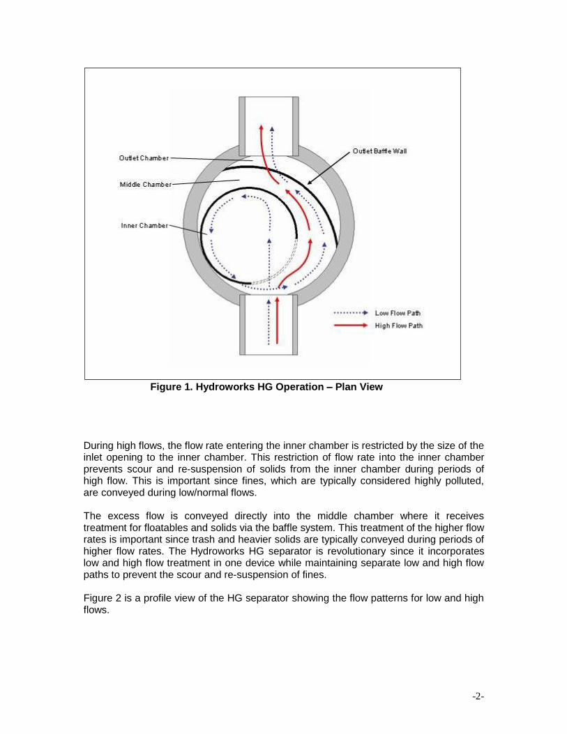
-2-
Figure 1. Hydroworks HG Operation – Plan View During high flows, the flow rate entering the inner chamber is restricted by the size of the inlet opening to the inner chamber. This restriction of flow rate into the inner chamber prevents scour and re-suspension of solids from the inner chamber during periods of high flow. This is important since fines, which are typically considered highly polluted, are conveyed during low/normal flows. The excess flow is conveyed directly into the middle chamber where it receives treatment for floatables and solids via the baffle system. This treatment of the higher flow rates is important since trash and heavier solids are typically conveyed during periods of higher flow rates. The Hydroworks HG separator is revolutionary since it incorporates low and high flow treatment in one device while maintaining separate low and high flow paths to prevent the scour and re-suspension of fines. Figure 2 is a profile view of the HG separator showing the flow patterns for low and high flows.
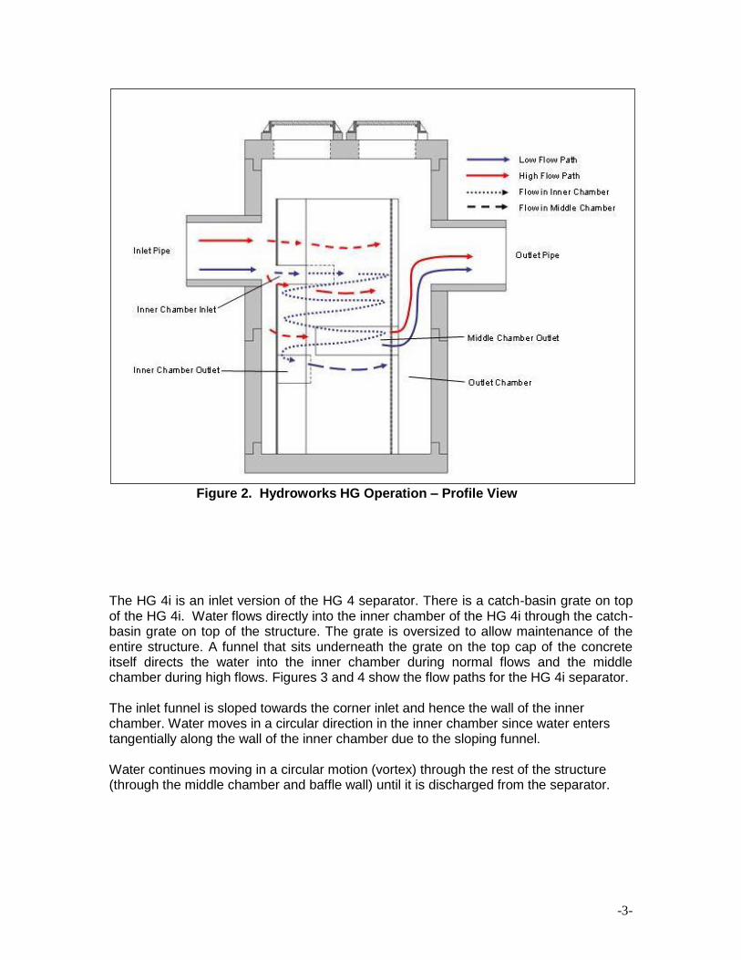
-3-
Figure 2. Hydroworks HG Operation – Profile View The HG 4i is an inlet version of the HG 4 separator. There is a catch-basin grate on top of the HG 4i. Water flows directly into the inner chamber of the HG 4i through the catch-basin grate on top of the structure. The grate is oversized to allow maintenance of the entire structure. A funnel that sits underneath the grate on the top cap of the concrete itself directs the water into the inner chamber during normal flows and the middle chamber during high flows. Figures 3 and 4 show the flow paths for the HG 4i separator. The inlet funnel is sloped towards the corner inlet and hence the wall of the inner chamber. Water moves in a circular direction in the inner chamber since water enters tangentially along the wall of the inner chamber due to the sloping funnel. Water continues moving in a circular motion (vortex) through the rest of the structure (through the middle chamber and baffle wall) until it is discharged from the separator.

-4-
During periods of peak flow the water will back up from the corner inlet and overflow into two side overflow troughs which discharge directly into the middle chamber. These overflow troughs are covered from the surface such that water cannot directly fall through them (i.e. water must back up to enter the overflow troughs). Accordingly this funnel provides the same separate flow paths for low and high flow as the other Hydroguard separators. The whole funnel is removed for inspection and cleaning providing.
Figure 3. Hydroworks HG 4i Normal Flow Path
Figure 4. Hydroworks HG 4i Peak Flow Path

-5-
Inspection Procedure Although all parts of the Hydroguard should be inspected, inspection and maintenance should focus on the inner and middle chambers since this is where the pollutants (floatable and sinking) will accumulate. Floatables A visual inspection can be conducted for floatables by removing the covers and looking down into the separator. Multiple covers are provided on Hydroworks HG units to access all areas of the separator (The HG 4 may have a single larger 32” (800mm) cover due to the lack of space for multiple 24” (600mm) covers). Separators with an inlet grate (HG4i or custom separator) will have a plastic funnel located under the grate or on the top cap of the concrete that must be removed through the frame prior to inspection or maintenance. If you are missing a funnel please contact Hydroworks at the numbers provided at the end of this document. TSS/Sediment Inspection for TSS build-up can be conducted using a Sludge Judge®, Core Pro®, AccuSludge® or equivalent sampling device that allows the measurement of the depth of TSS/sediment in the unit. These devices typically have a ball valve at the bottom of the tube that allows water and TSS to flow into the tube when lowering the tube into the unit. Once the unit touches the bottom of the device, it is quickly pulled upward such that the water and TSS in the tube forces the ball valve closed allowing the user to see a full core of water/TSS in the unit. The unit should be inspected for TSS through each of the access covers. Several readings (2 or 3) should be made at each access cover to ensure that an accurate TSS depth measurement is recorded. Frequency Construction Period The HG separator should be inspected every two weeks and after every large storm (over 0.5” (12.5 mm) of rain) during the construction period. Post-Construction Period The Hydroworks HG separator should be inspected once per year for normal stabilized sites (grassed or paved areas). If the unit is subject to oil spills or runoff from unstabilized (storage piles, exposed soils) areas the HG separator should be inspected more frequently (4 times per year). The initial annual inspection will indicate the required future frequency of maintenance if the unit was maintained after the construction period.

-6-
Reporting Reports should be prepared as part of each inspection and include the following information:
1. Date of inspection 2. GPS coordinates of Hydroworks unit 3. Time since last rainfall 4. Date of last inspection 5. Installation deficiencies (missing parts, incorrect installation of parts) 6. Structural deficiencies (concrete cracks, broken parts) 7. Operational deficiencies (leaks, blockages) 8. Presence of oil sheen or depth of oil layer 9. Estimate of depth/volume of floatables (trash, leaves) captured 10. Sediment depth measured 11. Recommendations for any repairs and/or maintenance for the unit 12. Estimation of time before maintenance is required if not required at time of
inspection A sample inspection checklist is provided at the end of this manual. Maintenance Procedure The Hydroworks HG unit is typically maintained using a vacuum truck. There are numerous companies that can maintain the HG separator. Maintenance with a vacuum truck involves removing all of the water and sediment together. The water is then separated from the sediment on the truck or at the disposal facility. In instances where a vacuum truck is not available other maintenance methods (i.e. clamshell bucket) can be used, but they will be less effective. If a clamshell bucket is used the water must be decanted prior to cleaning since the sediment is under water and typically fine in nature. Disposal of the water will depend on local requirements. Disposal options for the decanted water may include:
1. Discharge into a nearby sanitary sewer manhole 2. Discharge into a nearby LID practice (grassed swale, bioretention) 3. Discharge through a filter bag into a downstream storm drain connection
The local municipality should be consulted for the allowable disposal options for both water and sediments prior to any maintenance operation. Once the water is decanted the sediment can be removed with the clamshell bucket. Disposal of the contents of the separator depend on local requirements. Maintenance of a Hydroworks HG unit will typically take 1 to 2 hours based on a vacuum truck and longer for other cleaning methods (i.e. clamshell bucket).

-7-
Frequency Construction Period A HG separator can fill with construction sediment quickly during the construction period. The Hydroguard must be maintained during the construction period when the depth of TSS/sediment reaches 30” (750 mm). It must also be maintained during the construction period if there is an appreciable depth of oil in the unit (more than a sheen) or if floatables other than oil cover over 50% of the open water surface on the inlet side of the outlet baffle wall. The HG separator should be maintained at the end of the construction period, prior to operation for the post-construction period. Post-Construction Period The Hydroguard was independently tested by Alden Research Laboratory in 2008. A HG6 was tested for scour with initial sediment loads of 4.6 ft3 and 9.3 ft3. The results from these tests were almost identical. Therefore, the 9.3 ft3 sediment load was used as 50% of the maximum sediment depth for maintenance in the calculation of the maintenance interval for the HG6 separator based on the NJDEP maintenance equation. Maintenance Interval (months) = 3.565 x (Sediment Storage) / (MTFR x TSS Removal) Maintenance Interval (HG6) = 3.565 x 9.3 / (1.81x 0.60) = 30 months All values (flow, sediment storage) can be scaled by the surface area making the sediment depths and maintenance intervals equal for all separators. The separator was loaded with the sediment in the inner chamber and middle chamber with the majority of sediment (80%) located in the inner chamber. The inner chamber for area represents approximately 44% of the separator surface area. The inner chamber is 4 ft (1200 mm) in diameter in the HG6. Therefore the 50% sediment depth for the HG6 in the inner chamber would be: 9.3 ft3 x 0.80 / (3.14 x 4 ft2) x 12 in/ft = 7.1 inches (175 mm) Accordingly the 100% sediment volume would represent 14.2” (350 mm) of sediment depth in the inner chamber. The HG separator must be maintained if there is an appreciable depth of oil in the unit (more than a sheen) or if floatables other than oil cover over 50% of the open water surface on the inlet side of the outlet baffle wall. It should also be maintained once the accumulated TSS/sediment depths are greater than 14” (350 mm) in the inner chamber. For typical stabilized post-construction sites (parking lots, streets) it is anticipated that maintenance will be required annually or once every two years. More frequent or less frequent maintenance will be required depending on individual site conditions (traffic use, stabilization, storage piles, etc.). The long term maintenance frequency can be established based on the maintenance requirements during the first several years of operation if site conditions do not change.
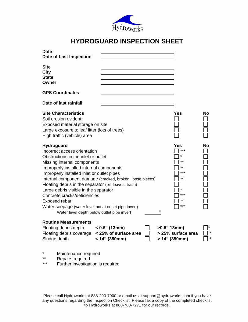
Please call Hydroworks at 888-290-7900 or email us at [email protected] if you have any questions regarding the Inspection Checklist. Please fax a copy of the completed checklist
to Hydroworks at 888-783-7271 for our records.
HYDROGUARD INSPECTION SHEET Date Date of Last Inspection Site City State Owner GPS Coordinates Date of last rainfall Site Characteristics Yes No
Soil erosion evident
Exposed material storage on site
Large exposure to leaf litter (lots of trees)
High traffic (vehicle) area
Hydroguard Yes No
Incorrect access orientation ***
Obstructions in the inlet or outlet *
Missing internal components **
Improperly installed internal components **
Improperly installed inlet or outlet pipes ***
Internal component damage (cracked, broken, loose pieces) **
Floating debris in the separator (oil, leaves, trash)
Large debris visible in the separator *
Concrete cracks/deficiencies ***
Exposed rebar **
Water seepage (water level not at outlet pipe invert) ***
Water level depth below outlet pipe invert “
Routine Measurements
Floating debris depth < 0.5” (13mm) >0.5” 13mm) *
Floating debris coverage < 25% of surface area > 25% surface area *
Sludge depth < 14” (350mm) > 14” (350mm) * * Maintenance required ** Repairs required *** Further investigation is required

-1-
Other Comments:
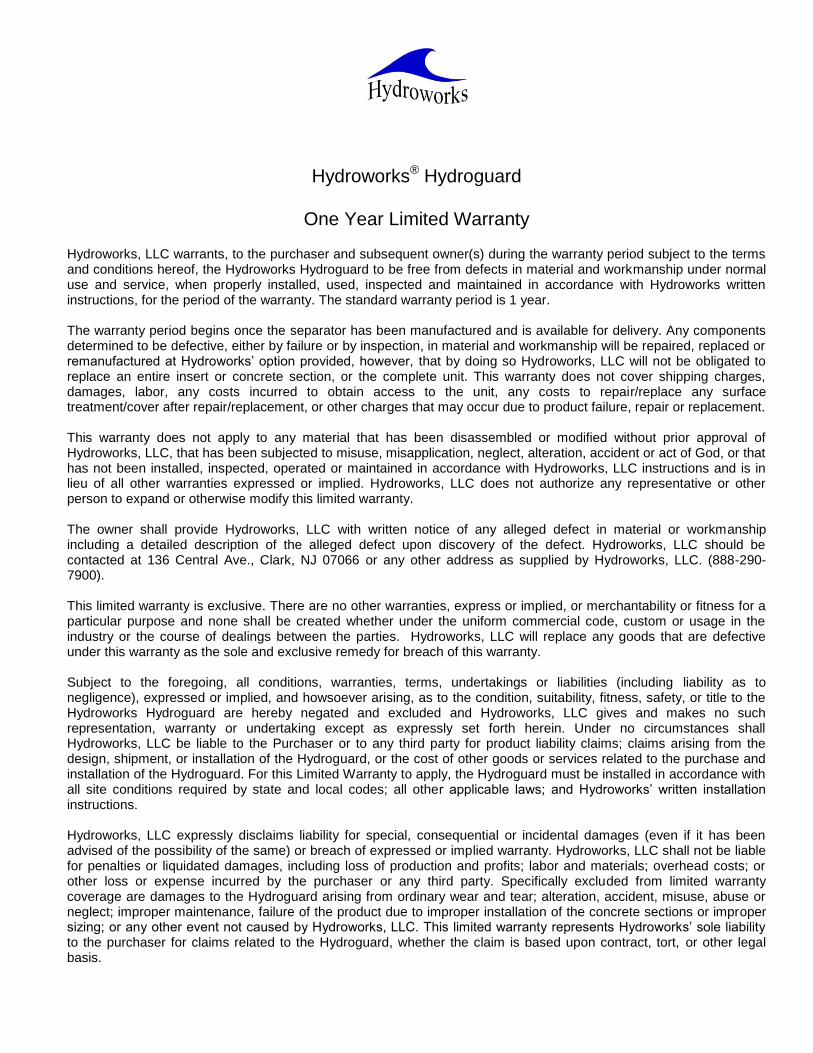
Hydroworks® Hydroguard
One Year Limited Warranty
Hydroworks, LLC warrants, to the purchaser and subsequent owner(s) during the warranty period subject to the terms and conditions hereof, the Hydroworks Hydroguard to be free from defects in material and workmanship under normal use and service, when properly installed, used, inspected and maintained in accordance with Hydroworks written instructions, for the period of the warranty. The standard warranty period is 1 year. The warranty period begins once the separator has been manufactured and is available for delivery. Any components determined to be defective, either by failure or by inspection, in material and workmanship will be repaired, replaced or remanufactured at Hydroworks’ option provided, however, that by doing so Hydroworks, LLC will not be obligated to replace an entire insert or concrete section, or the complete unit. This warranty does not cover shipping charges, damages, labor, any costs incurred to obtain access to the unit, any costs to repair/replace any surface treatment/cover after repair/replacement, or other charges that may occur due to product failure, repair or replacement. This warranty does not apply to any material that has been disassembled or modified without prior approval of Hydroworks, LLC, that has been subjected to misuse, misapplication, neglect, alteration, accident or act of God, or that has not been installed, inspected, operated or maintained in accordance with Hydroworks, LLC instructions and is in lieu of all other warranties expressed or implied. Hydroworks, LLC does not authorize any representative or other person to expand or otherwise modify this limited warranty. The owner shall provide Hydroworks, LLC with written notice of any alleged defect in material or workmanship including a detailed description of the alleged defect upon discovery of the defect. Hydroworks, LLC should be contacted at 136 Central Ave., Clark, NJ 07066 or any other address as supplied by Hydroworks, LLC. (888-290-7900). This limited warranty is exclusive. There are no other warranties, express or implied, or merchantability or fitness for a particular purpose and none shall be created whether under the uniform commercial code, custom or usage in the industry or the course of dealings between the parties. Hydroworks, LLC will replace any goods that are defective under this warranty as the sole and exclusive remedy for breach of this warranty. Subject to the foregoing, all conditions, warranties, terms, undertakings or liabilities (including liability as to negligence), expressed or implied, and howsoever arising, as to the condition, suitability, fitness, safety, or title to the Hydroworks Hydroguard are hereby negated and excluded and Hydroworks, LLC gives and makes no such representation, warranty or undertaking except as expressly set forth herein. Under no circumstances shall Hydroworks, LLC be liable to the Purchaser or to any third party for product liability claims; claims arising from the design, shipment, or installation of the Hydroguard, or the cost of other goods or services related to the purchase and installation of the Hydroguard. For this Limited Warranty to apply, the Hydroguard must be installed in accordance with all site conditions required by state and local codes; all other applicable laws; and Hydroworks’ written installation instructions. Hydroworks, LLC expressly disclaims liability for special, consequential or incidental damages (even if it has been advised of the possibility of the same) or breach of expressed or implied warranty. Hydroworks, LLC shall not be liable for penalties or liquidated damages, including loss of production and profits; labor and materials; overhead costs; or other loss or expense incurred by the purchaser or any third party. Specifically excluded from limited warranty coverage are damages to the Hydroguard arising from ordinary wear and tear; alteration, accident, misuse, abuse or neglect; improper maintenance, failure of the product due to improper installation of the concrete sections or improper sizing; or any other event not caused by Hydroworks, LLC. This limited warranty represents Hydroworks’ sole liability to the purchaser for claims related to the Hydroguard, whether the claim is based upon contract, tort, or other legal basis.

3 Perkins Way

3 Perkins Way
Appendix D
Figure 1 – Pre & Post Development Drainage Areas


DR BY:
CHK BY:
PROJ NO:
DATE:
SCALE:
SHT NO:
SHEET NAME:
STAMP:
REV DESCRIPTION DATE
PROJECT INFO
PROJECT TEAM
NORTH
DRAINAGE
AREAS
DA2
1" = 40'
MARCH 15, 2018
2017-137
RLB
SBS
ARCHITECT:
ANDREW SIDFORD ARCHITECTS
44 MERRIMAC STREET
NEWBURYPORT, MA 01950
978-462-1657
DEVELOPER:
BRADFORD & BIGELOW
3 PERKINS WAY
NEWBURYPORT, MA 01950
PHONE
PROJECT NAME
BUILDING ADDITION
3 PERKINS WAY
NEWBURYPORT, MA
Feet
0 40 80
P1
P2a
P2b
P2c
1. REVIEW COMMENTS 5/17/18