Embed Size (px)
Citation preview

Project Management
LectureNetwork Analysis

Introduction Project planning
Gantt chart and WBS
Project planning Network analysis I
Project planning Network analysis II
Introduction Project planning
Gantt chart and WBS
Project planning Network analysis I
Plan Project planning
Resource analysis Risk management Quality Budgets and cost
control Project teams
Plan
Monitor & Review
Plan
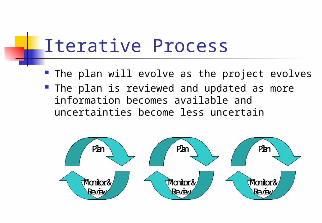
Iterative Process The plan will evolve as the project evolves The plan is reviewed and updated as more
information becomes available and uncertainties become less uncertain
Plan
Monitor & Review
Plan
Monitor & Review
Plan
Plan

PBS Example
Project
Design Deliverables
Database Deliverables
GUI Deliverables
Functional Deliverables
Project Management Deliverables
Produce Class Diagrams
Produce Use Cases
Produce Activity Diagrams

Use Case Describes a unit of functionality from
a users perspective May be text or diagram
Therefore they provide a good tool for Project Task Planning
They also can determine the nature of the project process How many development iterations?

Place Order
Send Payment
Retailer
Dispatch Order
Send Invioce
Raise Purchase Order
Make Payment
Staff
Priority 1
Priority 2
Use Case Example – Big John’s

Use Case Example – Big John’s Each Use Case Shown can be shown
as activities in the PBS The prioritisation can be used to
describe the activities for two development iterations
This will be significantly different to the process if only one iteration was used

Gantt Chart ExampleRepresent the following on a Gantt chart
Task Start (wk no) Duration (wks) %CompleteA 1 5 100B 2 3 100C 1 8 75D 3 4 100E 5 5 60F 2 4 25G 10 6 0H 6 6 100I 7 2 50J 8 6 50
Assume this information was taken at the end of week 8

Gantt Chart ExampleWeek
Task 1 2 3 4 5 6 7 8 9 10 11 12 13 14 15 16ABCDEFGHIJ
Scheduled Completion
Actual Completion
Under-fulfilled tasks: C, E, F, IOver-fulfilled tasks H, J

Gantt chart disadvantages Not ideal for showing inter-
relationships Locating an activity requires three
simultaneous decisions: Method Time Resources

Complexity Number of tasks? Number of people? Size of Budget? Number/Nature of constraints Dependencies between tasks

Why Network Diagrams? Splits up the decision making process
into Method/logic - the order in which tasks
have to be completed Time – estimates for the time to
completion can be added to each task Resources – these can be added and then
analysis carried out

Two Methods Activity on Arrow
Traditionally the preferred method Activity on Node
More popular these days Supported by most Project Management
software tools (i.e. MS Project)
A B
C
D
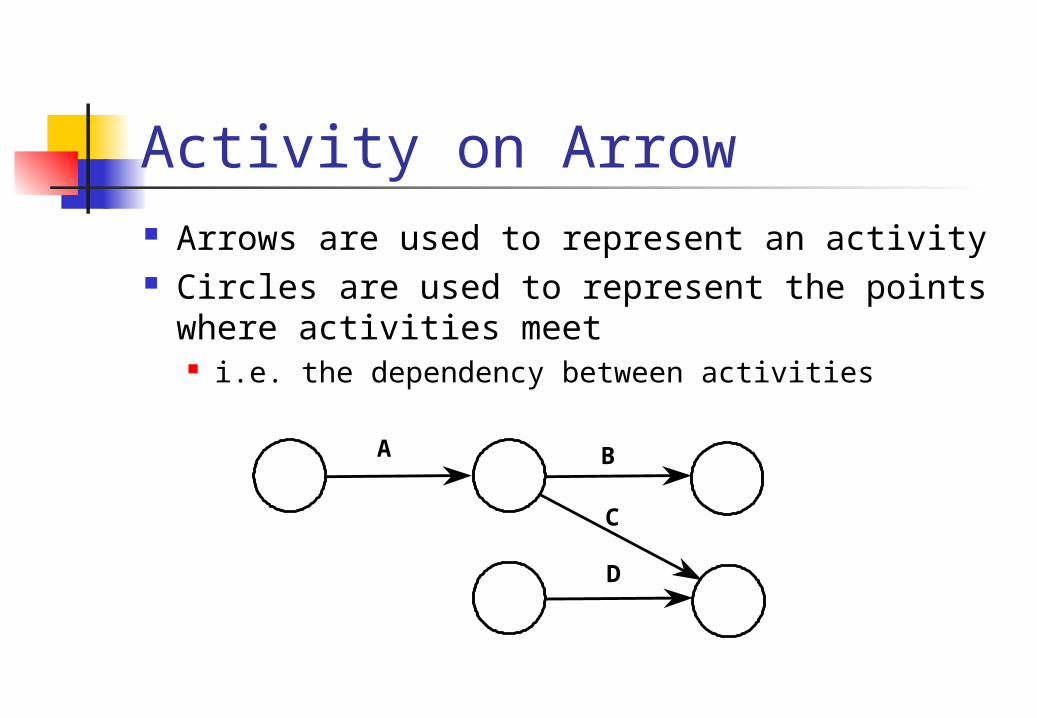
Activity on Arrow Arrows are used to represent an activity Circles are used to represent the points
where activities meet i.e. the dependency between activities
A B
C
D

Activity on Node Activities are
represented by boxes
Dependencies are represented by arrows joining the boxes
Task A
Task D
Task C
Task B

Comparison
A B
C
D
Task A
Task D
Task C
Task B

Task B cannot start until Task A is complete
Activity on Node
Activity on Arrow
Dependency Example Task B cannot start until Task A is
complete
Activity on Node
Task A Task B
Task A Task B

More complex example Four activities/tasks:
A, B, K, L Activity K is dependent on activity A Activity L is dependent on activities A and B
Task A
Task L Task B
Task K
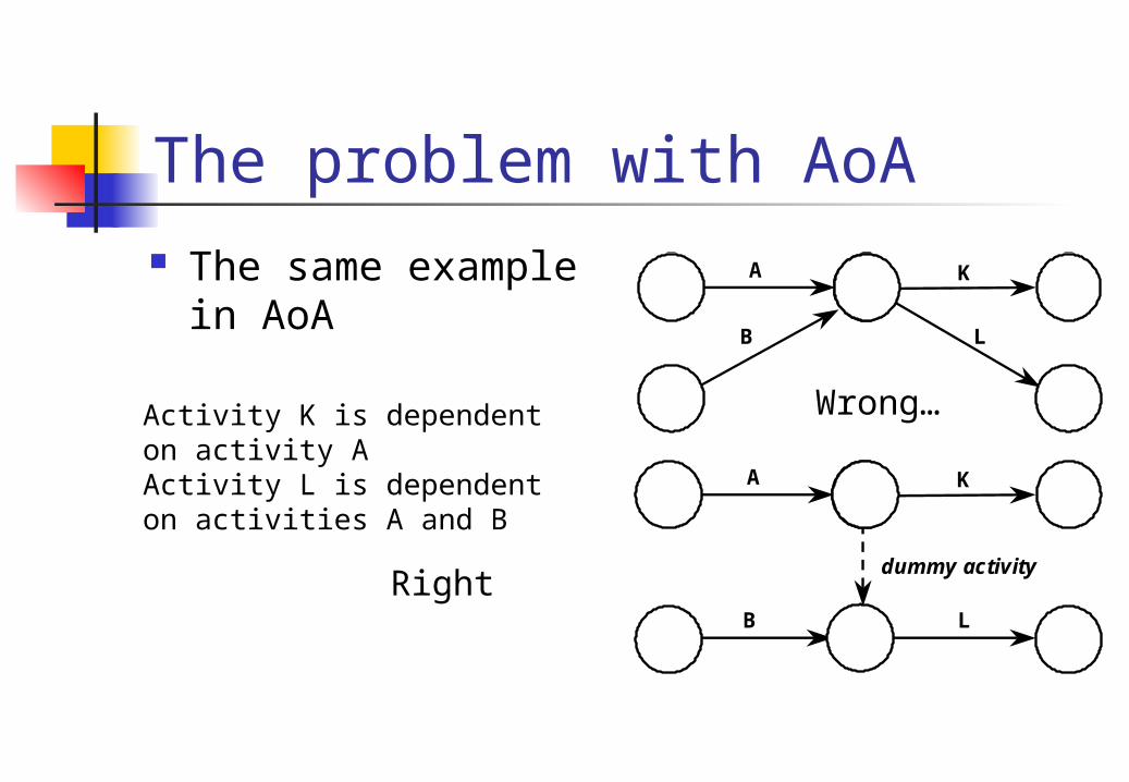
The same example in AoA
The same example in AoA
A K
The problem with AoA A K
L B
A K
L B
dummy activity
Wrong…
Right
Activity K is dependent on activity AActivity L is dependent on activities A and B

Exercise 1 Draw the following:
Activity K is dependant on Activity A Activity L is dependent on Activity B Activity M is dependent on Activity A and
B

Exercise 2 Draw the following:
Activity K is dependent on activities A and B
Activity L is dependent on activities B and C
Activity is dependent on activity B

Drawing the network Direction
The flow of work is from left to right Identifying Tasks
Each task is given a unique ID number ID number is often given in WBS

Scale Diagram is not drawn to scale Length and size do not matter
They have no meaning

What’s in the box?
Earliest Start
Estimated Duration
Earliest Finish
Activity NumberActivity Description
Latest Start
FloatLatest Finish

Project Exercise 1Project 1: Verification of a computer systemThe followng table shows the activities required for this project.
Activity ID Activity Immediate Predecessor
Duration (Days)
1 Test Module A none 42 Test Module B Test Module A 63 Test Module C none 74 Test Combined Modules Test Module B, Test Module C 45 Check User Documents Test Combined Modules 56 Print User Documents Check User Documents 27 Final Systems Check Test Combined Modules 98 Prepare Invoice Final Systems Check 19 Ship to Customer Print User Documents, Final
Systems Check2

Errors in Logic Looping
Due to a mistake in drawing or to errors in identifying dependent activities
P Q
R

Errors in Logic Dangling
Usually occur when activities are added as an afterthought
Can be avoided by using a single finish node
K L
M
K L
M
Finish

Project Exercise 2Project 2: A presentationThe followng table shows the activities required for this project.
Activity ID Activity Immediate Predecessor
Duration (Days)
1 Book Search none 122 Journal Search Book Search 63 Internet Search none 154 Produce Outline Journal Search, Internet Search 105 Prepare Handouts Produce Outline 76 Print Handouts Prepare Handouts 27 Produce Visual Aids Produce Outline 128 Write Speech Notes Produce Outline 49 Rehearse Speech Write Speech Notes 10
10 Give Presentation Print Handouts, Produce Visual Aids, Rehearse Speech
1

Introduction Project planning
Gantt chart and WBS
Project planning Network analysis I
Project planning Network analysis II
Project planning Network analysis I
Project planning Network analysis II
Plan Project planning
Resource analysis Risk management Quality Budgets and cost
control Project teams
Final thought for the day:Erm…