Embed Size (px)
Citation preview

PROJECT FOR THE
TERRE HAUTE DEPARTMENT OF REDEVELOPMENT
CITY HALL, ROOM 301
17 HARDING AVENUE
TERRE HAUTE, INDIANA
UNITED CEREBRAL PALSY OF THE WABASH VALLEY
1400 HULMAN STREET
TERRE HAUTE, IN 47802
CITY OF TERRE HAUTE
Duke Bennett, Mayor
TERRE HAUTE DEPARTMENT OF REDEVELOPMENT
Steve Witt, Executive Director
UNITED CEREBRAL PALSY OF THE WABASH VALLEY
Susie Thompson, Executive Director
PROJECT: CONSTRUCTION OF 2 DUPLEXES & 2 HOUSES
OWNER: UNITED CEREBRAL PALSY OF THE WABASH VALLEY
REDEVELOPMENT COMMISSIONERS
David I. Heath, Brian F. Conley, Paul Lockhart, Jim L. Nichols, Troy Helman
UNITED CEREBRAL PALSY OF THE WABASH VALLEY EXECUTIVE BOARD
Deb Stephens, Jared McCullough, Susie Thompson, Pam Deady
Project Certified By:
Daniel E. Sanders, AIA
Prepared by:
SANDERS & ASSOCIATES, INC.
611 Deming Street
Terre Haute, IN 47807
July 7, 2016

Table of Contents
Page 1 of 3
TABLE OF CONTENTS
FOR PROJECT MANUAL
A. Cover Page
B. Table of Contents
C. Invitation to Bid
D. Instruction to Bidders
E. Bid Form 96
F. Bid Form Attachment
G. Supplemental General Conditions
H. Contractor’s Non-Collusion Affidavit
I. Non-Collusion Affidavit of Subcontractors
J. Notice of Requirement for Affirmative Action to Ensure Equal Employment Opportunity
K. Executive Order 11246
L. Subcontractor’s Equal Employment Opportunity/Executive Order 11246
M. Contractor’s Certification Regarding Drug-Free Workplace
N. Subcontractor’s Certification Regarding Drug-Free Workplace
O. Contractor’s Certification of Anti-Lobbying
P. Subcontractor’s Certification of Anti-Lobbying
Q. Certificate of Non-Segregated Facilities
R. Subcontractor’s Certificate of Non-Segregated Facilities
S. Proposed List of Subcontractors
Appendix A. Contract Provisions
The bid packets items A-S and Appendix A, are available at Rapid Reproductions, Inc. 129 S.
11th
St. Terre Haute, IN Phone: 812-238-1681 or at www.sandersandassocplanroom.com.
ITEMS T- Z-3 are not included. These items are Standard AIA Documents (Most current
editions) and may be examined at the Architect’s office.
T. Bid Bond (AIA Document A310)
U. Standard form of Agreement Between Owner and Contractor (AIA Document A107, 2007
edition)
V. Performance Bond and Payment Bond (AIA Document A312)
W. Change Order (AIA Document G701)
X. Application and Certificate for Payment (AIA Document G702 & G703)
Y. Certificate of Insurance (AIA Document G715)
Z. Contractor’s Affidavit of Payment of Debts and Claims (AIA Document G706)
Z-1 Contractor’s Affidavit of Release of Liens (AIA Document G706A)
Z-2 Consent of Surety Company to Final Payment (AIA Document G707)
Z-3 Proposal Request (AIA Document G709)

Table of Contents
Page 2 of 3
DIVISION ONE - GENERAL REQUIREMENTS
01070 Cutting and Patching
01085 Applicable Standards
01300 Submittals and Substitutions and Shop Drawings
01485 Temporary Facilities and Controls
01710 Cleaning
01720 Project Record Documents
DIVISION TWO - SITE CONSTRUCTION
02200 Excavating, Filling, and Grading
02281 Termite Control
02520 Asphaltic Paving & Surfacing
DIVISION THREE - CONCRETE
03100 Concrete Formwork
03110 Concrete Work
03210 Steel Reinforcement for Concrete
03362 Stained Concrete
DIVISION FOUR - MASONRY
04100 Mortar
04150 Masonry Accessories
04200 Unit Masonry
DIVISION FIVE - METAL
05200 Miscellaneous Metals
DIVISION SIX - WOOD AND PLASTIC
06001 Carpentry Work
06210 Interior Finish Carpentry
06240 Laminated Plastic
06410 Cabinetwork
DIVISION SEVEN - THERMAL AND MOISTURE PROTECTION
07212 Insulation
07311 Asphalt Shingles
07323 Stone Coated Metal Roof Panels
07620 Sheet Metal Flashing and Trim
07951 Sealants and Caulking

Table of Contents
Page 3 of 3
DIVISION EIGHT - DOORS AND WINDOWS
08210 Wood Doors
08221 Fiberglass Reinforced Door and Frame System
08522 Vinyl Clad Windows
08710 Finish Hardware
DIVISION NINE - FINISHES
09260 Gypsum Wallboard
09660 Resilient Flooring
09775 Sanitary Wall Finish
09900 Painting
DIVISION TEN - SPECIALITIES
10670 Storage Shelving
10800 Toilet Room Accessories
DIVISIONS ELEVEN THROUGH FOURTEEN
NOT USED
DIVISION FIFTEEN - MECHANICAL
15400 Plumbing
15600 Heating, Ventilating and Air Conditioning
DIVISION SIXTEEN - ELECTRICAL
16001 Electrical
Drawings: Refer to Drawing T-1 for an index to drawings.

INVITATION TO BID
United Cerebral Palsy of the Wabash Valley, Inc. (UCP) will receive sealed bids for the construction
of two (2) duplexes and two (2) houses on the UCP site, 1400 Hulman St. in the City of Terre Haute,
Indiana until 10:30 AM on the 28th day of July, 2016, at the office of the Department of
Redevelopment, City Hall, 17 Harding Ave., Room 301, Terre Haute, Indiana at which time and place
all bids will be publicly opened and read aloud.
Bids will be received on the basis of a single lump sum and alternates for complete construction as
described in the Instructions to Bidders. Contractors may bid package (A) two (2) Duplexes or
package (B) two (2) Houses or both packages (A) & (B). The work is to include all labor, materials,
equipment, tools and appliances, transportation, all applicable taxes, permits and everything required
for the entire performance and completion of the work in every detail.
All work shall be in strict accordance with this Invitation to Bid and the bidding Contract Documents
as prepared by Sanders & Associates, Inc. Any bids received after the above specified time and date
will be returned to bidders unopened. Bids shall be accompanied by the General Contractor’s
Proposal Contents as stated in the specifications.
Bidding and Contract Documents including Drawings and Specifications may be examined in the
office of the architect, Sanders & Associates, Inc., 611 Deming St., Terre Haute, Indiana, 47807, (812)
232-5256, or at www.Sandersandassocplanroom.com, or at the Dept. of Redevelopment, City Hall, 17
Harding Avenue, Room 301, Terre Haute, Indiana (812) 244-2393.
Plans and specifications will be available for distribution July 7, 2016. The plans and specifications
must be purchased directly from Rapid Reproductions, 129 S. 11th St., Terre Haute, IN 47807, with no
deposit required, or online at www.Sandersandassocplanroom.com . No bids shall be withdrawn for a
period of sixty-(60) calendar days after the bid opening without written consent of the Architect.
Do not include sales tax in the bid amount. The owner is exempt from payment of Indiana Sales Tax
and Use Tax. The owner will furnish the contractor with the necessary exemption number upon
request.
A certified check or bank draft, payable to the order of United Cerebral Palsy of the Wabash Valley,
Inc., negotiable U.S. Government Bonds (at par value), or a satisfactory Bid Bond executed by the
Bidder and acceptable surety, in an amount equal to five percent (5%) of the total amount of the bid
shall be submitted with each bid.
Bid Guaranty will be returned to unsuccessful bidders upon selection of the successful bidder. Bid
Guaranty of the successful bidder will be returned upon the signing of contracts. Bids may be held not
to exceed sixty-(60) days from the date of Bid Opening for the purpose of reviewing the Bids and
investigating the qualifications of the Bidders, prior to the award of a Contract.
Contractor receiving award shall furnish at the directive of the Owner, an approved Performance
Bond, Labor and Material Payment Bond in an amount at least equal to 100% of the contract amount,
or an irrevocable line of credit for 25% of the total construction contract. The line of credit must be
issued for the entire construction period plus one (1) year following construction completion.

The bidders are requested to meet with the owner and architect for a pre-bid conference at the office of
the Department of Redevelopment, City Hall, 17 Harding Ave., Terre Haute, IN on Monday, July 18,
2016 at 11:00 AM local time.
Contractors shall be aware that no less than minimum salaries and wages must be paid on this project.
The Contractor must insure that all employees and applicants for employment are not discriminated
against because of their race, religion, color, sex, national origin, or individuals with handicaps.
Women and Minority Owned Businesses qualified to perform the work contemplated by this
solicitation are encouraged to bid.
The work to be performed under this contract is on a project assisted under a program providing direct
Federal financing assistance from the Department of Housing and Urban Development and is subject
to the requirements of Section 3 of the Housing and Urban Development Act of 1968, as amended, 12
U.S.C. 1701u, and Executive Order 11246 as amended.
United Cerebral Palsy of the Wabash Valley, Inc. does business in accordance with the Federal Fair
Housing Laws and promotes fair housing in the community. It is illegal to discriminate against any
person because of race, color, religion, sex, handicap, family status, or national origin; in the sale or
rental of housing or residential lots, in advertising the sale or rental of housing, in the financing of
housing, in the provision of real estate brokerage services, in the appraisal of housing, and
blockbusting is also illegal.
The time completion of the project shall be 135 days after the notice to proceed. United Cerebral Palsy
of the Wabash Valley, Inc. reserves the right to reject any or all bids or waive any informality in the
bidding to the extent permitted by law.
Each bid must be enclosed in a sealed envelope marked:
Bid For: United Cerebral Palsy of the Wabash Valley, Inc.
Construction of 2 Duplexes and 2 Houses
Bid opening Thursday, July 28, 2016 at 10:30 AM
“Name and Address of Bidder”
Agent: Dan Sanders, Architect
Sanders & Associates, Inc.
611 Deming Street
Terre Haute, IN 47807
812-232-5256
Dated this 5th day of July, 2016
Instructions to Bidders
Page 1 of 4
INSTRUCTIONS TO BIDDERS
1. SECURING DOCUMENTS
Copies of the proposed Contract Documents are on file at the following offices:
Department of Redevelopment
City Hall, Room 301
17 Harding Avenue
Terre Haute, IN 47807
Architect:
Sanders & Associates, Inc.
611 Deming Street
Terre Haute, IN 47807
The bid packets, plans and specifications are available for purchase at Rapid Reproductions,
Inc. 129 S. 11th
St., Terre Haute, IN (Phone # 812-238-1681) or online at
www.sandersandassocplanroom.com
Copies of the proposed Contract Documents may be obtained for bidding purposes upon the
conditions set forth in the Invitation to Bid.
2. BID FORM
In order to receive consideration, make all bids in strict accordance with the following:
1) Make bids upon the forms provided therefore, with bids as shown properly executed and
with all items filled out. Do not change the wording of the Bid Form, and do not add
words to the wording of the Bid Form. Unauthorized conditions, limitations or
provisions attached to the proposal shall be cause for rejection of the proposal.
Alterations by erasure or interlineation must be explained or noted in the bid over the
signature of the bidder.
Total Complete Construction Bid for the construction of Package “A” - 2 duplexes or
Package “B” - 2 houses or Packages “A” and “B”.
2) No telegraphic bid or telegraphic modification of bid will be considered. No bids
received after the time fixed for receiving them will be considered. Late bids will be
returned to the sender unopened.
3) Each bid shall be addressed to the Owner, and shall be delivered to the Owner at the
address given on or before the day and hour set for opening of the bids. Each bid shall be
enclosed in a sealed envelope bearing the title of the work, the name of the bidder, and
the date and hour of the bid opening. It is the sole responsibility of the bidder to see that
his bid is received on time.
Instructions to Bidders
Page 2 of 4
3. EXAMINATION OF DRAWINGS, SPECIFICATIONS, AND SITE OF WORK
Before submitting a bid, each bidder shall carefully examine the Drawings, READ the
Specifications and all other proposed Contract Documents, and visit the site of the Work.
Each bidder shall fully inform himself prior to bidding as to all existing conditions and
limitations under which the Work is to be performed, and he shall include in his bid a sum to
cover all costs of all items necessary to perform the work as set forth in the proposed
Contract Documents. No allowances will be made to any bidder because of lack of such
examination or knowledge. The submission of a bid will be construed as conclusive
evidence that the bidder has made such examination.
4. WITHDRAWAL OF BIDS
Any bidder may withdraw his bid, either personally or by written request, at any time prior to
the scheduled time for opening bids. No bidder may withdraw his bid for a period of 60 days
after the date set for opening thereof, and all bids shall be subject to acceptance by the Owner
during this period.
5. AWARD OR REJECTION OF BIDS
The Contract will be awarded based on the low bid. The Owner also reserves the right to
reject the Bid of any bidder who has previously failed to perform properly, or in a timely
manner, or to complete an item, contracts of similar nature, who is not in a position to
perform the Contract, or who has habitually and without just cause neglected the payment of
bills or otherwise disregarded his obligations to subcontractors, materialmen, or employees.
The Contract is intended to be awarded to the apparent and best low bidder. In the case of
the acceptance of any alternates, it will be the lowest net or aggregate including the alternates
that the Owner accepts. The Owner reserves the right to accept any bid and to waive any
formalities.
6. EXECUTION OF AGREEMENT
The form of Agreement which the successful bidder, as Contractor, will be required to
execute, is included in the Project Manual:
1) The bidder to whom the contract is awarded by the Owner shall, within 7 days after
notice of award and receipt of Agreement form from the Owner, sign and deliver to the
Architect all required copies.
2) At or prior to delivery of the signed Agreement, the Contractor shall deliver to the
Architect the policies of insurance certificates as required by the Contract Documents.
All bonds and policies of insurance shall be approved by the Owner before the successful
bidder may proceed with the work.

Instructions to Bidders
Page 3 of 4
3) Failure or refusal to furnish bonds or insurance policies or certificates in a form
satisfactory to the Owner shall subject the bidder to loss of time from the allowable
construction period equal to the time delay in furnishing the required material.
7. INTERPRETATION OF CONTRACT DOCUMENTS PRIOR TO BIDDING
If any person contemplating submitting a bid for construction of the Work is in doubt as to
the true meaning of any part of the proposed Contract Documents, or finds discrepancies in
or omissions from any part of the proposed Contract Documents, he may submit to the
Architect a written request for interpretation thereof not later than seven days before bids will
be opened.
1) The person submitting the request shall be responsible for its prompt delivery.
2) Interpretation or correction of proposed Contract Documents will be made only by
Addendum, and will be mailed or delivered to each bidder of record. All Addenda will
be a part of the Contract.
3) The Owner will not be responsible for any other explanations or interpretations of the
proposed Documents.
8. CONSTRUCTION TIME AND LIQUIDATED DAMAGES
The Agreement will include a stipulation that work be completed in 135 days. The
Agreement will also include a stipulation that liquidated damages will be established in the
amount of $100.00 per calendar day after the completion date that the work is not fully
completed and certificate of occupancy issued.
9. PERFORMANCE BOND
A performance and payment bond in a penal sum of 100 percent of the contract price; or as
may be required or permitted by State law, or an irrevocable line of credit listing United
Cerebral Palsy, Inc., as the sole beneficiary for 25% of the total construction contract. The
line of credit must be issued for the entire construction period plus one (1) year following
construction completion.
10. COMPLETION OF SPECIFICATIONS AND PLANS
Upon issue to prospective bidders the physical make-up and content of the plans,
specifications and extra proposal forms are intended to be complete for preparing and
submitting of proposals. However, the bidder will verify to his own satisfaction that all
material issued him is complete. Should he discover that a page, sheet, etc., is missing, he
shall notify the Architect in writing and it will be forwarded to him. After bids have been
submitted, no claim of ignorance of the requirements of bidding or of construction due to
such missing material will be recognized.
Instructions to Bidders
Page 4 of 4
11. PROPOSAL CONTENTS
All bids shall include properly executed forms as follows:
1) Bid Security
2) Bid Form 96
3) Bid Form Attachment
4) Non-Collusion Affidavits*
5) EEO Certificates*
6) Drug Free Work Place Certification*
7) Anti-Lobbying Certificates*
8) Non-Segregated Facilities*
9) Section 3 Plan* #
10) Proposed List of Subcontractors with addresses and phone numbers
The general contractor shall submit all the above items with their proposals, except the item
marked with a # sign. The item marked with a # sign will be submitted before the Notice to
Proceed is issued.
* All subcontractors shall submit these forms before the Notice to Proceed is issued.
# All subcontractors shall submit Item G- Section 3 Plan before the Notice to Proceed is
issued, if their contracts are over $100,000.00.
12. WAGES
Attention of bidders is called to the fact that no less than minimum salaries and wages must
be paid on this project.
13. PRE-BID MEETING
A Pre-Bid meeting will be at the Department of Redevelopment, City Hall Room 301, 17
Harding Ave., Terre Haute, IN on Monday, July 18th
, 2016 at 11:00am local time.

PART I (To be completed for all bids. Please type or print)
Date (month, day, year):__________________________
1. Governmental Unit (Owner):___________________________________________________________
2. County :___________________________________________________________________________
3. Bidder (Firm):_______________________________________________________________________
Address:___________________________________________________________________________
City/State/ZIPcode:__________________________________________________________________
4. Telephone Number:__________________________________________________________________
5. Agent of Bidder (if applicable):__________________________________________________________
Pursuant to notices given, the undersigned offers to furnish labor and/or material necessary to complete
the public works project of _____________________________________________________________________
(Governmental Unit) in accordance with plans and specifications prepared by _____________________________
_________________________________________________ and dated _____________________ for the sum of
____________________________________________________ $_____________________________________
The undersigned further agrees to furnish a bond or certified check with this bid for an amount specified in the notice of the letting. If alternative bids apply, the undersigned submits a proposal for each in accordance with the notice. Any addendums attached will be specifically referenced at the applicable page.
If additional units of material included in the contract are needed, the cost of units must be the same as that shown in the original contract if accepted by the governmental unit. If the bid is to be awarded on a unit basis, the itemization of the units shall be shown on a separate attachment.
The contractor and his subcontractors, if any, shall not discriminate against or intimidate any employee, or applicant for employment, to be employed in the performance of this contract, with respect to any matter directly or indirectly related to employment because of race, religion, color, sex, national origin or ancestry. Breach of this covenant may be regarded as a material breach of the contract.
CERTIFICATION OF USE OF UNITED STATES STEEL PRODUCTS (If applicable)
I, the undersigned bidder or agent as a contractor on a public works project, understand my statutory obligation to use steel products made in the United States (I.C. 5-16-8-2). I hereby certify that I and all subcontractors employed by me for this project will use U.S. steel products on this project if awarded. I understand that violations hereunder may result in forfeiture of contractual payments.
CONTRACTOR'S BID FOR PUBLIC WORK - FORM 96 State Form 52414 (R / 9-10) / Form 96 (Revised 2010) Prescribed by State Board of Accounts

ACCEPTANCE
The above bid is accepted this _____________ day of _________________, ________, subject to the
following conditions: _______________________________________________________________________
________________________________________________________________________________________
Contracting Authority Members:
______________________________________ _______________________________________
______________________________________ _______________________________________
______________________________________ _______________________________________
PART II (For projects of $100,000 or more – IC 36-1-12-4)
Governmental Unit: ___________________________________________________________
Bidder (Firm) ___________________________________________________________
Date (month, day, year): _______________________________________________________
These statements to be submitted under oath by each bidder with and as a part of his bid. Attach additional pages for each section as needed.
SECTION I EXPERIENCE QUESTIONNAIRE
1. What public works projects has your organization completed for the period of one (1) year prior to the date of the current bid?
Contract Amount
Class of Work
Completion Date
Name and Address of Owner
2. What public works projects are now in process of construction by your organization?
Contract Amount
Class of Work
ExpectedCompletion
Date
Name and Address of Owner
3. Have you ever failed to complete any work awarded to you? _______________ If so, where and why?
__________________________________________________________________________________
__________________________________________________________________________________
__________________________________________________________________________________
4. List references from private firms for which you have performed work.
__________________________________________________________________________________
__________________________________________________________________________________
__________________________________________________________________________________
__________________________________________________________________________________
__________________________________________________________________________________
SECTION II PLAN AND EQUIPMENT QUESTIONNAIRE
1. Explain your plan or layout for performing proposed work. (Examples could include a narrative of when you could begin work, complete the project, number of workers, etc. and any other information which you believe would enable the governmental unit to consider your bid.)
__________________________________________________________________________________
__________________________________________________________________________________
__________________________________________________________________________________
__________________________________________________________________________________
__________________________________________________________________________________
2. Please list the names and addresses of all subcontractors (i.e. persons or firms outside your own firm who have performed part of the work) that you have used on public works projects during the past five (5) years along with a brief description of the work done by each subcontractor.
__________________________________________________________________________________
__________________________________________________________________________________
__________________________________________________________________________________
__________________________________________________________________________________
__________________________________________________________________________________
3. If you intend to sublet any portion of the work, state the name and address of each subcontractor, equipment to be used by the subcontractor, and whether you will require a bond. However, if you are unable to currently provide a listing, please understand a listing must be provided prior to contract approval. Until the completion of the proposed project, you are under a continuing obligation to immediately notify the governmental unit in the event that you subsequently determine that you will use a subcontractor on the proposed project.
__________________________________________________________________________________ __________________________________________________________________________________ __________________________________________________________________________________ __________________________________________________________________________________ __________________________________________________________________________________ 4. What equipment do you have available to use for the proposed project? Any equipment to be used by
subcontractors may also be required to be listed by the governmental unit. __________________________________________________________________________________ __________________________________________________________________________________ __________________________________________________________________________________ __________________________________________________________________________________ __________________________________________________________________________________ 5. Have you entered into contracts or received offers for all materials which substantiate the prices used in
preparing your proposal? If not, please explain the rationale used which would corroborate the prices listed.
__________________________________________________________________________________ __________________________________________________________________________________ __________________________________________________________________________________ __________________________________________________________________________________ __________________________________________________________________________________
SECTION III CONTRACTOR’S FINANCIAL STATEMENT
Attachment of bidder’s financial statement is mandatory. Any bid submitted without said financial statement as required by statute shall thereby be rendered invalid. The financial statement provided hereunder to the governing body awarding the contract must be specific enough in detail so that said governing body can make a proper determination of the bidder’s capability for completing the project if awarded.
SECTION IV CONTRACTOR'S NON – COLLUSION AFFIDAVIT
The undersigned bidder or agent, being duly sworn on oath, says that he has not, nor has any other member, representative, or agent of the firm, company, corporation or partnership represented by him, entered into any combination, collusion or agreement with any person relative to the price to be bid by anyone at such letting nor to prevent any person from bidding nor to include anyone to refrain from bidding, and that this bid is made without reference to any other bid and without any agreement, understanding or combination with any other person in reference to such bidding.
He further says that no person or persons, firms, or corporation has, have or will receive directly or indirectly, any rebate, fee, gift, commission or thing of value on account of such sale.
SECTION V OATH AND AFFIRMATION
I HEREBY AFFIRM UNDER THE PENALTIES FOR PERJURY THAT THE FACTS AND INFORMATION CONTAINED IN THE FOREGOING BID FOR PUBLIC WORKS ARE TRUE AND CORRECT.
Dated at ____________________ this ______________ day of __________________, _______
__________________________________________________________ (Name of Organization)
By________________________________________________________
__________________________________________________________ (Title of Person Signing)
ACKNOWLEDGEMENT
STATE OF ______________________) ) ss COUNTY OF_____________________)
Before me, a Notary Public, personally appeared the above-named _________________________________ and
swore that the statements contained in the foregoing document are true and correct.
Subscribed and sworn to before me this ____________ day of ___________________, ________.
____________________________________________ Notary Public
My Commission Expires:_____________________
County of Residence:________________________

Part of State Form 52414 (R / 9-10) / Form 96 (Revised 2010)
BID OF
________________________________________________________
(Contractor)
________________________________________________________ (Address)
_____________________________________________
FOR
PUBLIC WORKS PROJECTS
OF
________________________________
_____________________________________
_____________________________________
Filed ________________________________, _______
Action taken __________________________________
_____________________________________

Bid Form Attachment
Page 1 of 3
BID FORM ATTACHMENT
To City of Terre Haute, Department of Redevelopment, 17 Harding Avenue, Terre Haute,
Indiana and United cerebral Palsy of the Wabash Valley, Inc. 1400 Hulman Street, Terre
Haute, Indiana for the Construction of 2 Duplexes and 2 Houses.
United Cerebral Palsy of the Wabash Valley, Inc.
1422/1418 Hulman Street – Unit E 1560 S. 14th Street – Plan D
1414/1410 Hulman Street – Unit F 1568 S. 14th Street – Plan B
Bidding Contractors:
1. Pursuant to and in compliance with the invitation to bid and the proposed Contract
Documents relating to refacing of cabinets, including any addenda, the undersigned, having
become thoroughly familiar with the terms and conditions of the proposed Contract
Documents and with the local conditions affecting the performance and costs of the work at
the places where the work is to be completed, and having inspected the sites in all particulars,
hereby purposes and agrees to fully perform the work within the time stated and in strict
accordance with the proposed Contract Documents, including furnishing any and all labor
and materials, and to do all of the work required to construct and complete said work in
accordance with the Contract Documents, for the following sum of money:
2. I understand that the Owner reserves the right to reject this bid, but that this bid shall remain
open and not withdrawn for a period of sixty days from the date prescribed for its opening.
3. If written notice of the acceptance of this bid is mailed or delivered to the undersigned within
thirty days after the date set for the opening of this bid, or at any other time thereafter before
it is withdrawn, the undersigned will execute and deliver the Contract Documents to the
Architect in accordance with this bid as accepted, and will also furnish and deliver to the
Architect, Proof of Insurance Coverage and a 100% Performance Bond and Payment Bond
within seven days after personal delivery or an irrevocable letter of credit with of acceptance
of this bid.
4. If awarded a contract under this proposal, the undersigned agrees to start work within seven
(7) days of the contract signing, Notice of Acceptance, or request for additional information,
may be addressed to the undersigned at the address set forth below:

Bid Form Attachment
Page 2 of 3
5. ADDENDA CONFIRMATION
Bidder here with acknowledges receipt and has incorporated the provisions of the following
addenda in this bid.
Addendum Number Date
_____________________________________ ___________________
_____________________________________ ___________________
_____________________________________ ___________________
_____________________________________ ___________________
_____________________________________ ____________________
_____________________________________ ____________________
_____________________________________ ____________________
_____________________________________ ____________________

Bid Form Attachment
Page 3 of 3
BID FORM ITEMIZATION
UNITED CEREBRAL PALSY OF THE WABASH VALLEY
(Construction of 2 Duplexes and 2 Houses)
PACKAGE A – 2 DUPLEXES
_______________________________________ ___________________ COMPLETE CONSTRUCTION BID (IN WRITING) (IN FIGURES)
PACKAGE B – 2 HOUSES
_______________________________________ ___________________ COMPLETE CONSTRUCTION BID (IN WRITING) (IN FIGURES)
PACKAGES A & B – 2 DUPLEXES & 2 HOUSES
_______________________________________ ___________________ COMPLETE CONSTRUCTION BID (IN WRITING) (IN FIGURES)
DATE: _________________________, 2016
____________________________________
(FIRM NAME)
OFFICIAL ADDRESS:
__________________________________ By: ______________________
__________________________________ Title: _____________________
PHONE: ________________________________

SUPPLEMENTAL GENERAL CONDITIONS
PAGE 1 OF 5
SUPPLEMENTAL GENERAL CONDITIONS
1. COPIES OF DOCUMENTS,
2. INSURANCE AND BONDS, ARTICLE 17, ADD THE FOLLOWING PARAGRAPHS:
A. The Contractor shall not commence work under this contract until he has obtained all
insurance required by these specifications and until such insurance has been approved by
the Owner, nor shall the Contractor allow any Subcontractor to commence work on his
subcontract until all similar insurance required of the Subcontractor has been obtained
and approved. Policies expiring on a fixed date before final acceptance of the project
must be renewed and evidence of such renewal submitted to the Owner before such date.
B. The Contractor shall furnish the Owner with satisfactory evidence of the insurance
required.
C. All policies and/or policy certificates shall contain the following clauses:
1. Worker’s Compensation Insurance: The Contractor shall maintain during the life of
this contract Worker’s Compensation Insurance for all employees employed at the
site of the project, and, in case any work is sublet, the Contractor must require the
Subcontractor similarly to provide Worker’s Compensation Insurance for all of his
employees engaged in work under this contract at the site of the project. The
Contractor shall provide insurance coverage equal to that provided under the
Worker’s Compensation Act, for the protection of his employees not otherwise
protected. Employer’s liability coverage must be maintained in amount not less than
100,000/500,000/100,000.
2. Public Liability Property Damage: The Contractor shall maintain during the life of
this contract Commercial General Liability Insurance. Such coverage shall protect
him and any Subcontractor performing work covered by this contract, from claims for
damages for personal injury, including accidental death, as well as from claims for
property damages, which may arise from operations under this contract, whether such
operations be by himself or by any Subcontractor or by anyone directly or indirectly
employed by either of them and the amounts of such insurance shall be as follows:
Commercial General Liability Insurance in an amount not less than $1,000,000 per
occurrence for Bodily Injury, Property Damage, Personal and Advertising Injury with
a $1,000,000 general aggregate and a $1,000,000 Products and Completed Operations
aggregate.
The Contractor shall require all of its Subcontractors, if not protected under
Contractor’s insurance policies, to effect and maintain, at their own expense during
the entire period of performance and until completion of the subcontract, Commercial
General Liability Insurance with a company or companies to the satisfaction of the
Owner as follows:
SUPPLEMENTAL GENERAL CONDITIONS
PAGE 2 OF 5
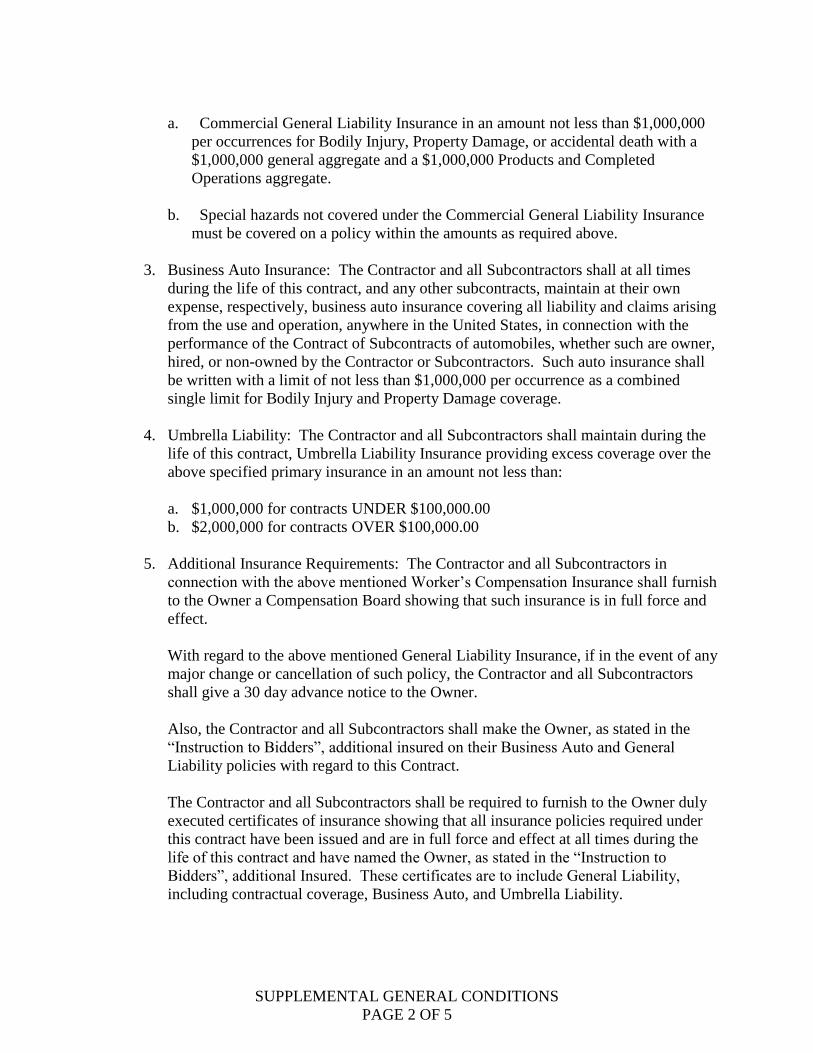
a. Commercial General Liability Insurance in an amount not less than $1,000,000
per occurrences for Bodily Injury, Property Damage, or accidental death with a
$1,000,000 general aggregate and a $1,000,000 Products and Completed
Operations aggregate.
b. Special hazards not covered under the Commercial General Liability Insurance
must be covered on a policy within the amounts as required above.
3. Business Auto Insurance: The Contractor and all Subcontractors shall at all times
during the life of this contract, and any other subcontracts, maintain at their own
expense, respectively, business auto insurance covering all liability and claims arising
from the use and operation, anywhere in the United States, in connection with the
performance of the Contract of Subcontracts of automobiles, whether such are owner,
hired, or non-owned by the Contractor or Subcontractors. Such auto insurance shall
be written with a limit of not less than $1,000,000 per occurrence as a combined
single limit for Bodily Injury and Property Damage coverage.
4. Umbrella Liability: The Contractor and all Subcontractors shall maintain during the
life of this contract, Umbrella Liability Insurance providing excess coverage over the
above specified primary insurance in an amount not less than:
a. $1,000,000 for contracts UNDER $100,000.00
b. $2,000,000 for contracts OVER $100,000.00
5. Additional Insurance Requirements: The Contractor and all Subcontractors in
connection with the above mentioned Worker’s Compensation Insurance shall furnish
to the Owner a Compensation Board showing that such insurance is in full force and
effect.
With regard to the above mentioned General Liability Insurance, if in the event of any
major change or cancellation of such policy, the Contractor and all Subcontractors
shall give a 30 day advance notice to the Owner.
Also, the Contractor and all Subcontractors shall make the Owner, as stated in the
“Instruction to Bidders”, additional insured on their Business Auto and General
Liability policies with regard to this Contract.
The Contractor and all Subcontractors shall be required to furnish to the Owner duly
executed certificates of insurance showing that all insurance policies required under
this contract have been issued and are in full force and effect at all times during the
life of this contract and have named the Owner, as stated in the “Instruction to
Bidders”, additional Insured. These certificates are to include General Liability,
including contractual coverage, Business Auto, and Umbrella Liability.
SUPPLEMENTAL GENERAL CONDITIONS
PAGE 3 OF 5
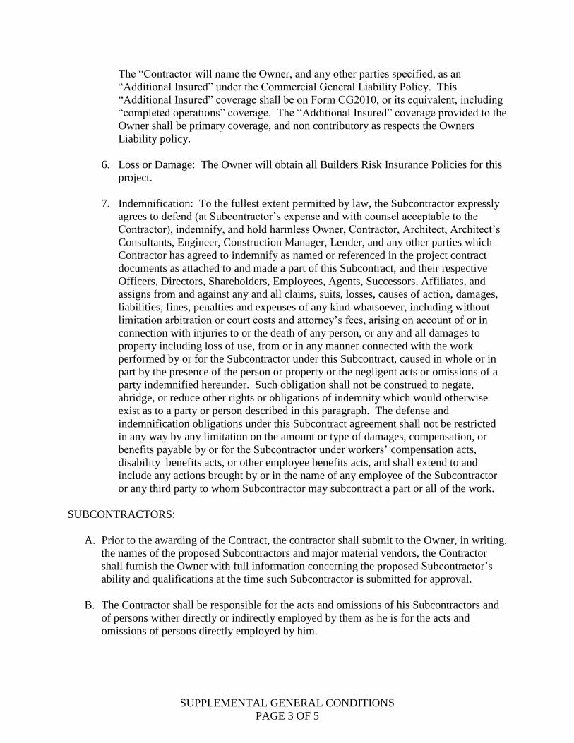
The “Contractor will name the Owner, and any other parties specified, as an
“Additional Insured” under the Commercial General Liability Policy. This
“Additional Insured” coverage shall be on Form CG2010, or its equivalent, including
“completed operations” coverage. The “Additional Insured” coverage provided to the
Owner shall be primary coverage, and non contributory as respects the Owners
Liability policy.
6. Loss or Damage: The Owner will obtain all Builders Risk Insurance Policies for this
project.
7. Indemnification: To the fullest extent permitted by law, the Subcontractor expressly
agrees to defend (at Subcontractor’s expense and with counsel acceptable to the
Contractor), indemnify, and hold harmless Owner, Contractor, Architect, Architect’s
Consultants, Engineer, Construction Manager, Lender, and any other parties which
Contractor has agreed to indemnify as named or referenced in the project contract
documents as attached to and made a part of this Subcontract, and their respective
Officers, Directors, Shareholders, Employees, Agents, Successors, Affiliates, and
assigns from and against any and all claims, suits, losses, causes of action, damages,
liabilities, fines, penalties and expenses of any kind whatsoever, including without
limitation arbitration or court costs and attorney’s fees, arising on account of or in
connection with injuries to or the death of any person, or any and all damages to
property including loss of use, from or in any manner connected with the work
performed by or for the Subcontractor under this Subcontract, caused in whole or in
part by the presence of the person or property or the negligent acts or omissions of a
party indemnified hereunder. Such obligation shall not be construed to negate,
abridge, or reduce other rights or obligations of indemnity which would otherwise
exist as to a party or person described in this paragraph. The defense and
indemnification obligations under this Subcontract agreement shall not be restricted
in any way by any limitation on the amount or type of damages, compensation, or
benefits payable by or for the Subcontractor under workers’ compensation acts,
disability benefits acts, or other employee benefits acts, and shall extend to and
include any actions brought by or in the name of any employee of the Subcontractor
or any third party to whom Subcontractor may subcontract a part or all of the work.
SUBCONTRACTORS:
A. Prior to the awarding of the Contract, the contractor shall submit to the Owner, in writing,
the names of the proposed Subcontractors and major material vendors, the Contractor
shall furnish the Owner with full information concerning the proposed Subcontractor’s
ability and qualifications at the time such Subcontractor is submitted for approval.
B. The Contractor shall be responsible for the acts and omissions of his Subcontractors and
of persons wither directly or indirectly employed by them as he is for the acts and
omissions of persons directly employed by him.
SUPPLEMENTAL GENERAL CONDITIONS
PAGE 4 OF 5
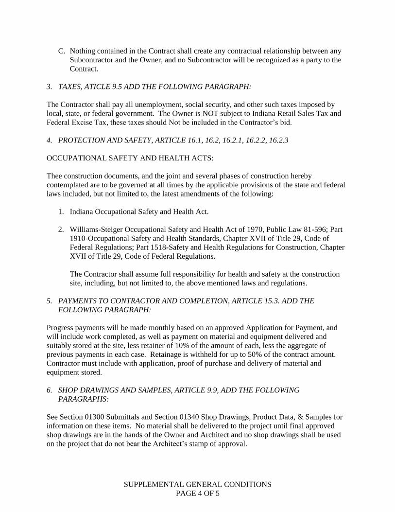
C. Nothing contained in the Contract shall create any contractual relationship between any
Subcontractor and the Owner, and no Subcontractor will be recognized as a party to the
Contract.
3. TAXES, ATICLE 9.5 ADD THE FOLLOWING PARAGRAPH:
The Contractor shall pay all unemployment, social security, and other such taxes imposed by
local, state, or federal government. The Owner is NOT subject to Indiana Retail Sales Tax and
Federal Excise Tax, these taxes should Not be included in the Contractor’s bid.
4. PROTECTION AND SAFETY, ARTICLE 16.1, 16.2, 16.2.1, 16.2.2, 16.2.3
OCCUPATIONAL SAFETY AND HEALTH ACTS:
Thee construction documents, and the joint and several phases of construction hereby
contemplated are to be governed at all times by the applicable provisions of the state and federal
laws included, but not limited to, the latest amendments of the following:
1. Indiana Occupational Safety and Health Act.
2. Williams-Steiger Occupational Safety and Health Act of 1970, Public Law 81-596; Part
1910-Occupational Safety and Health Standards, Chapter XVII of Title 29, Code of
Federal Regulations; Part 1518-Safety and Health Regulations for Construction, Chapter
XVII of Title 29, Code of Federal Regulations.
The Contractor shall assume full responsibility for health and safety at the construction
site, including, but not limited to, the above mentioned laws and regulations.
5. PAYMENTS TO CONTRACTOR AND COMPLETION, ARTICLE 15.3. ADD THE
FOLLOWING PARAGRAPH:
Progress payments will be made monthly based on an approved Application for Payment, and
will include work completed, as well as payment on material and equipment delivered and
suitably stored at the site, less retainer of 10% of the amount of each, less the aggregate of
previous payments in each case. Retainage is withheld for up to 50% of the contract amount.
Contractor must include with application, proof of purchase and delivery of material and
equipment stored.
6. SHOP DRAWINGS AND SAMPLES, ARTICLE 9.9, ADD THE FOLLOWING
PARAGRAPHS:
See Section 01300 Submittals and Section 01340 Shop Drawings, Product Data, & Samples for
information on these items. No material shall be delivered to the project until final approved
shop drawings are in the hands of the Owner and Architect and no shop drawings shall be used
on the project that do not bear the Architect’s stamp of approval.

SUPPLEMENTAL GENERAL CONDITIONS
PAGE 5 OF 5
7. EQUAL EMPLOYMENT OPPORTUNITY:
Attention of Bidders is particularly called to the requirement for ensuring that employees and
applicants for employment are not discriminated against because of their race, creed, color, sex
or national origin. Attention of Bidders is also particularly called to the requirements for
ensuring that, to the greatest extent feasible, in connection with work covered by this contract,
opportunities for training and employment be made to lower income residents of the project area
and that contract work shall be awarded to business concerns which are located in or owned
substantially by residents of the Project Area.
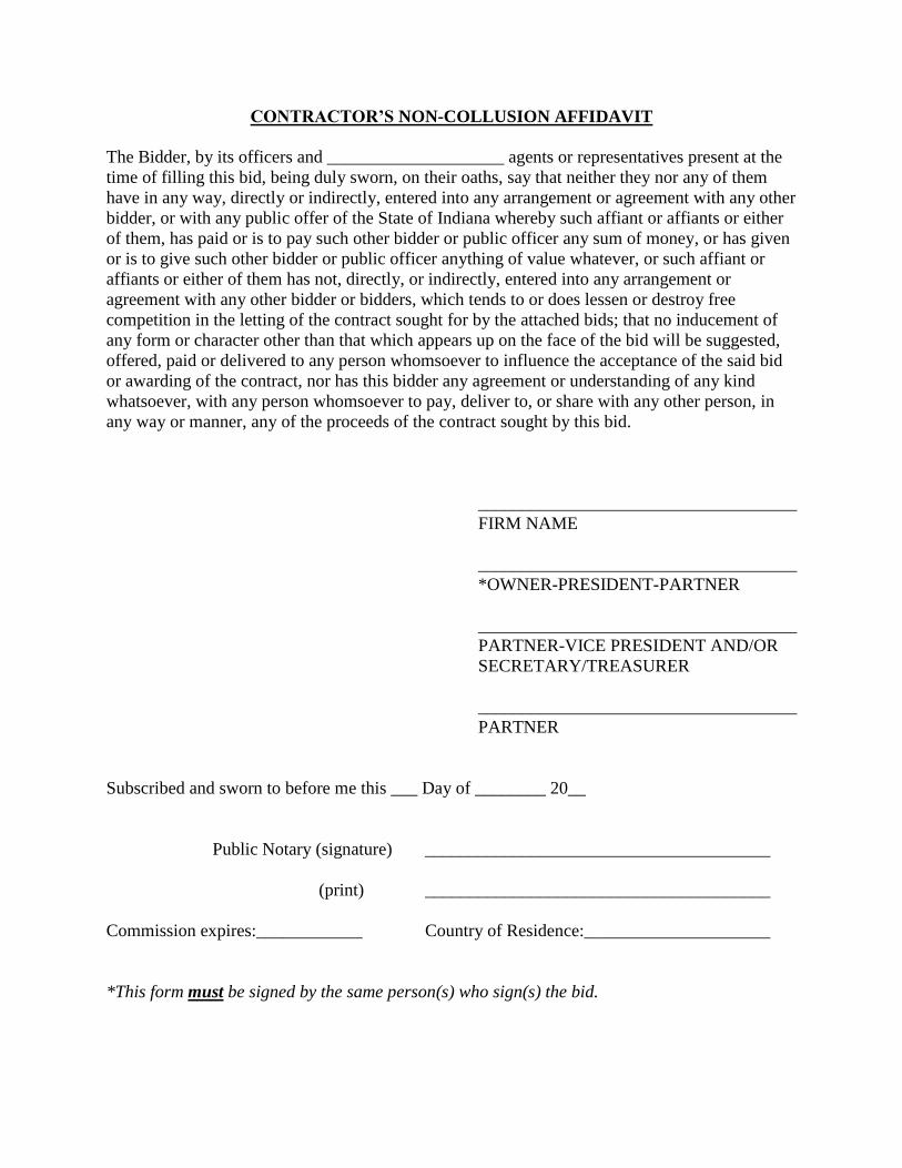
CONTRACTOR’S NON-COLLUSION AFFIDAVIT
The Bidder, by its officers and ____________________ agents or representatives present at the
time of filling this bid, being duly sworn, on their oaths, say that neither they nor any of them
have in any way, directly or indirectly, entered into any arrangement or agreement with any other
bidder, or with any public offer of the State of Indiana whereby such affiant or affiants or either
of them, has paid or is to pay such other bidder or public officer any sum of money, or has given
or is to give such other bidder or public officer anything of value whatever, or such affiant or
affiants or either of them has not, directly, or indirectly, entered into any arrangement or
agreement with any other bidder or bidders, which tends to or does lessen or destroy free
competition in the letting of the contract sought for by the attached bids; that no inducement of
any form or character other than that which appears up on the face of the bid will be suggested,
offered, paid or delivered to any person whomsoever to influence the acceptance of the said bid
or awarding of the contract, nor has this bidder any agreement or understanding of any kind
whatsoever, with any person whomsoever to pay, deliver to, or share with any other person, in
any way or manner, any of the proceeds of the contract sought by this bid.
____________________________________
FIRM NAME
____________________________________
*OWNER-PRESIDENT-PARTNER
____________________________________
PARTNER-VICE PRESIDENT AND/OR
SECRETARY/TREASURER
____________________________________
PARTNER
Subscribed and sworn to before me this ___ Day of ________ 20__
Public Notary (signature) _______________________________________
(print) _______________________________________
Commission expires:____________ Country of Residence:_____________________
*This form must be signed by the same person(s) who sign(s) the bid.

SUBCONTRACTOR’S NON-COLLUSION AFFIDAVIT
State of _______________
County of _______________
______________________________________, being first duly shown, deposes and says that:
1) He/She is _____________________________ of _________________________.
Hereinafter referred to as the “Subcontractor”;
2) He/She is fully informed respecting the preparation and contents of the subcontractor’s
Proposal submitted to the subcontractor to ________________, the Contractor for certain
work in connection with the____________________ Contract pertaining to the Project in
_____________________________;
3) Such subcontractor’s Proposal is genuine and is not a collusive or sham proposal;
4) Neither the subcontractor nor any of its officers, partners, owners, agents, representatives,
employees or parties in interest, including this affiant, has in any way colluded, conspired,
connived, or agreed, directly or indirectly, with any other Bidder, firm or person to submit a
collusive or sham Proposal in connection with such contractor or to refrain from submitting a
Proposal in connection with such contract, or has in any manner, directly or indirectly,
sought by unlawful agreement or connivance with any other Bidder, firm or person to fix the
price or prices in said subcontractor’s Proposal, or to secure through collusion, conspiracy,
connivance or unlawful agreement any advantage against the _________________________
and
5) The price or prices quoted in the subcontractor’s Proposal are fair and proper and are not
tainted by any collusion, conspiracy, connivance or unlawful agreement on the part of the
Bidder or any of its agents, representatives, owner, employees, or parties in interest,
including this affiant.
____________________________________
SIGNATURE
Subscribed and sworn to before me this ___ Day of ________ 20__
Public Notary (signature) _______________________________________
(print) _______________________________________
Commission expires:____________ Country of Residence:_____________________
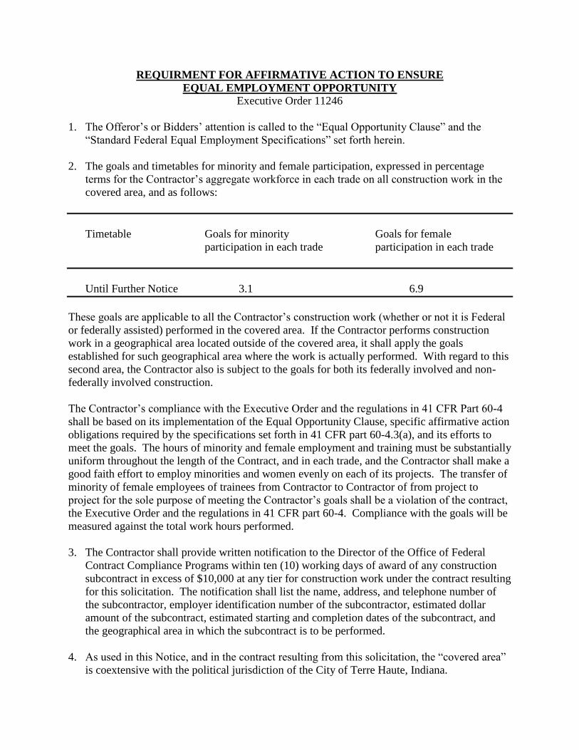
REQUIRMENT FOR AFFIRMATIVE ACTION TO ENSURE
EQUAL EMPLOYMENT OPPORTUNITY
Executive Order 11246
1. The Offeror’s or Bidders’ attention is called to the “Equal Opportunity Clause” and the
“Standard Federal Equal Employment Specifications” set forth herein.
2. The goals and timetables for minority and female participation, expressed in percentage
terms for the Contractor’s aggregate workforce in each trade on all construction work in the
covered area, and as follows:
Timetable Goals for minority Goals for female
participation in each trade participation in each trade
Until Further Notice 3.1 6.9
These goals are applicable to all the Contractor’s construction work (whether or not it is Federal
or federally assisted) performed in the covered area. If the Contractor performs construction
work in a geographical area located outside of the covered area, it shall apply the goals
established for such geographical area where the work is actually performed. With regard to this
second area, the Contractor also is subject to the goals for both its federally involved and non-
federally involved construction.
The Contractor’s compliance with the Executive Order and the regulations in 41 CFR Part 60-4
shall be based on its implementation of the Equal Opportunity Clause, specific affirmative action
obligations required by the specifications set forth in 41 CFR part 60-4.3(a), and its efforts to
meet the goals. The hours of minority and female employment and training must be substantially
uniform throughout the length of the Contract, and in each trade, and the Contractor shall make a
good faith effort to employ minorities and women evenly on each of its projects. The transfer of
minority of female employees of trainees from Contractor to Contractor of from project to
project for the sole purpose of meeting the Contractor’s goals shall be a violation of the contract,
the Executive Order and the regulations in 41 CFR part 60-4. Compliance with the goals will be
measured against the total work hours performed.
3. The Contractor shall provide written notification to the Director of the Office of Federal
Contract Compliance Programs within ten (10) working days of award of any construction
subcontract in excess of $10,000 at any tier for construction work under the contract resulting
for this solicitation. The notification shall list the name, address, and telephone number of
the subcontractor, employer identification number of the subcontractor, estimated dollar
amount of the subcontract, estimated starting and completion dates of the subcontract, and
the geographical area in which the subcontract is to be performed.
4. As used in this Notice, and in the contract resulting from this solicitation, the “covered area”
is coextensive with the political jurisdiction of the City of Terre Haute, Indiana.
CONTRACTOR
EQUAL EMPLOYMENT OPPORTUNITY
Executive Order 11246
(30 F.R. 12319-25)
Sec. 202. Except in contracts exempted in accordance with Section 204 of this order, all
Government contracting agencies shall include in every Government contract hereafter entered
into the following provisions:
“During the performance of this contract, the contractor agrees as follows:
1) The contractor will not discriminate against any employee or applicant for employment
because of race, color, religion, sex, or national origin. The contractor will take affirmative
action to ensure that applicants are employed, and that employees are treated during
employment, without regard to their race, color, religion, sex or national origin. Such action
shall include, but not be limited to the following: employment, upgrading, demotion or
transfer; recruitment advertising; layoff or termination, rates of pay or other forms of
compensation; and selection for training, including apprenticeship. The contractor agrees to
post in a conspicuous place, available to employees and applicants for employment, notices
to be provided by the contracting offer setting forth the provision of this nondiscrimination
clause.
2) The contractor will, in all solicitations or advertisements for employees placed by or on
behalf of the contractor, state that all qualified applicants will receive consideration for
employment without regard to race, color, religion, sex, or national origin.
3) The contractor will send to each labor union or representative of workers with which he/she
has collective bargaining agreement or other contract or understanding, a notice to be
provided by the agency contracting officer, advising the labor union of workers’
representative of the contractors’ commitments under Section 202 of Executive Order No.
11246 of September 24, 1965, and shall post copies of the notice in conspicuous places
available to employees and applicants for employment.
4) The contractor will comply with all provisions of Executive Order No. 1124 of September
24, 1965, and of the rules, regulations, and relevant orders of the Secretary of Labor.
5) The contract will furnish all information and reports required by Executive Order No. 11246
of September 24, 1965, and by the rules, regulations, and orders of the Secretary of Labor for
purposes of investigation to ascertain compliance with each rule, regulation and order.
6) In the event of the contractor’s non-compliance with the nondiscrimination clauses of the
contract or with any such rules, regulations, or orders, this contract may be cancelled,
terminated or suspended in whole or part, the contractor may be declared ineligible for
Government contracts in accordance with procedures authorized in Executive Order No.
11246 of September 24, 1965, or by rule, regulation, or order of the Secretary of Labor, or as
otherwise provided by law.

7) The contract will include the provisions of paragraphs (1) through (7) in every subcontract or
purchase order unless exempted by rules, regulations, or orders of the Secretary of Labor
pursuant to Section 202 of Executive Order No. 11246 of September 24, 1965, so that such
provisions will be binding action with respect to any subcontract or purchase order as the
Department may direct as a means of enforcing such provisions including sanctions for non-
compliance; Provided however, that in the event the contractor becomes involved in, or is
threatened with, litigation with a sub-contractor or vendor as a result of such direction by the
Department, the contractor may request the United States to enter into such litigation to
protect the interest of the United States.
THIS COMPANY WILL COMPLY WITH THE PROVISIONS OF SECTIONS 202 OF
EXECUTIVE ORDER 11246
Name of Firm:______________________________________
Address: __________________________________________
Signature: _________________________________________
Printed: ___________________________________________
Date: _____________________________________________

SUBCONTRACTOR
EQUAL EMPLOYMENT OPPORTUNITY
Executive Order 11246
(30 F.R. 12319-25)
Sec. 202. Except in contracts exempted in accordance with Section 204 of this order, all
Government contracting agencies shall include in every Government contract hereafter entered
into the following provisions:
“During the performance of this contract, the contractor agrees as follows:
1) The contractor will not discriminate against any employee or applicant for employment
because of race, color, religion, sex, or national origin. The contractor will take affirmative
action to ensure that applicants are employed, and that employees are treated during
employment, without regard to their race, color, religion, sex or national origin. Such action
shall include, but not be limited to the following: employment, upgrading, demotion or
transfer; recruitment advertising; layoff or termination, rates of pay or other forms of
compensation; and selection for training, including apprenticeship. The contractor agrees to
post in a conspicuous place, available to employees and applicants for employment, notices
to be provided by the contracting offer setting forth the provision of this nondiscrimination
clause.
2) The contractor will, in all solicitations or advertisements for employees placed by or on
behalf of the contractor, state that all qualified applicants will receive consideration for
employment without regard to race, color, religion, sex, or national origin.
3) The contractor will send to each labor union or representative of workers with which he/she
has collective bargaining agreement or other contract or understanding, a notice to be
provided by the agency contracting officer, advising the labor union of workers’
representative of the contractors’ commitments under Section 202 of Executive Order No.
11246 of September 24, 1965, and shall post copies of the notice in conspicuous places
available to employees and applicants for employment.
4) The contractor will comply with all provisions of Executive Order No. 1124 of September
24, 1965, and of the rules, regulations, and relevant orders of the Secretary of Labor.
5) The contract will furnish all information and reports required by Executive Order No. 11246
of September 24, 1965, and by the rules, regulations, and orders of the Secretary of Labor for
purposes of investigation to ascertain compliance with each rule, regulation and order.
6) In the event of the contractor’s non-compliance with the nondiscrimination clauses of the
contract or with any such rules, regulations, or orders, this contract may be cancelled,
terminated or suspended in whole or part, the contractor may be declared ineligible for
Government contracts in accordance with procedures authorized in Executive Order No.
11246 of September 24, 1965, or by rule, regulation, or order of the Secretary of Labor, or as
otherwise provided by law.

7) The contract will include the provisions of paragraphs (1) through (7) in every subcontract or
purchase order unless exempted by rules, regulations, or orders of the Secretary of Labor
pursuant to Section 202 of Executive Order No. 11246 of September 24, 1965, so that such
provisions will be binding action with respect to any subcontract or purchase order as the
Department may direct as a means of enforcing such provisions including sanctions for non-
compliance; Provided however, that in the event the contractor becomes involved in, or is
threatened with, litigation with a sub-contractor or vendor as a result of such direction by the
Department, the contractor may request the United States to enter into such litigation to
protect the interest of the United States.
THIS COMPANY WILL COMPLY WITH THE PROVISIONS OF SECTIONS 202 OF
EXECUTIVE ORDER 11246
Name of Firm:______________________________________
Address: __________________________________________
Signature: _________________________________________
Printed: ___________________________________________
Date: _____________________________________________

CONTRACTOR’S CERTIFICATE REGARDING
DRUG-FREE WORK PLACE
The Contractor certifies that it will provide a drug-free workplace by:
1. Publishing a Statement notifying employees that the unlawful manufacture, distribution,
dispensing, possession; or use of a controlled substance is prohibited in the contractor’s
workplace and specifying the actions that will be taken against employees for violation of
such prohibition.
2. Establishing an ongoing drug-free awareness program to inform employee about:
a. The dangers of drug abuse in the workplace
b. The Contractor’s policy of maintaining a drug-free workplace
c. Any available drug counseling, rehabilitation, and employee assistance programs
d. The penalties that may be imposed upon employees for drug abuse violation
occurring in the workplace
3. Giving each employee to be engaged in the performance of work on this contract a copy of
the above required statement.
4. Notifying the employee in the required Statement that, as a condition of employment on this
Contract, the employee will:
a. Abide by the terms of the Statement; and
b. Notify the employer in writing of his or her conviction for a violation of a criminal
drug stature occurring in the workplace no later than five calendar days after such
conviction.
5. Notifying the Contracting Officer in writing, within ten calendar days after receiving notice
under subparagraph 4 (b) from an employee of otherwise receiving actual notice of such
conviction. Employers of convicted employees must provide notice, including position title,
to every Contracting Officer or other designee on whose Contract activity the convicted
employee was working. Notice shall include the identification number (s) of the Contract of
funding Grant.
6. Taking one of the following actions, within 30 calendar days of receiving notice under
paragraph 4 (b), with respect to any employee who is so convicted –
a. Taking appropriate personnel action against such an employee, up to and
including termination, consistent with the requirements of the Rehabilitation Act
of 1973, as amended, or
b. Requiring such employee to participate satisfactorily in a drug abuse assistance or
rehabilitation program approved for such purpose by a Federal, State, or local
health, law enforcement, or other appropriate agency.
DATE: COMPANY:
SIGNATURE: PRINTED:

SUBCONTRACTOR’S CERTIFICATE REGARDING
DRUG-FREE WORK PLACE
The subcontractor certifies that it will provide a drug-free workplace by:
1. Publishing a Statement notifying employees that the unlawful manufacture, distribution,
dispensing, possession; or use of a controlled substance is prohibited in the contractor’s
workplace and specifying the actions that will be taken against employees for violation of
such prohibition.
2. Establishing an ongoing drug-free awareness program to inform employee about:
a. The dangers of drug abuse in the workplace
b. The Contractor’s policy of maintaining a drug-free workplace
c. Any available drug counseling, rehabilitation, and employee assistance programs
d. The penalties that may be imposed upon employees for drug abuse violation
occurring in the workplace
3. Giving each employee to be engaged in the performance of work on this contract a copy of
the above required statement.
4. Notifying the employee in the required Statement that, as a condition of employment on this
Contract, the employee will:
a. Abide by the terms of the Statement; and
b. Notify the employer in writing of his or her conviction for a violation of a criminal
drug stature occurring in the workplace no later than five calendar days after such
conviction.
5. Notifying the Contracting Officer in writing, within ten calendar days after receiving notice
under subparagraph 4 (b) from an employee of otherwise receiving actual notice of such
conviction. Employers of convicted employees must provide notice, including position title,
to every Contracting Officer or other designee on whose Contract activity the convicted
employee was working. Notice shall include the identification number (s) of the Contract of
funding Grant.
6. Taking one of the following actions, within 30 calendar days of receiving notice under
paragraph 4 (b), with respect to any employee who is so convicted –
a. Taking appropriate personnel action against such an employee, up to and
including termination, consistent with the requirements of the Rehabilitation Act
of 1973, as amended, or
b. Requiring such employee to participate satisfactorily in a drug abuse assistance or
rehabilitation program approved for such purpose by a Federal, State, or local
health, law enforcement, or other appropriate agency.
DATE: SIGNATURE:
SIGNATURE:

CONTRACTOR’S CERTIFICATE OF
ANTI-LOBBYING
The Contractor certifies that to the best of his/her knowledge and belief that:
1. No Federal appropriated funds have been paid or will be paid, by or on behalf of the
contractor, to any person for influencing or attempting to influence an officer or employee of
any agency, a Member of Congress, an officer or employee of Congress, or an employee of a
Member of Congress in connection with the awarding of any Federal contract, the making of
any Federal loan, the entering into of any cooperative agreement, and the extension,
continuation, renewal, amendment, or modification of any Federal contract, grant, loan, or
cooperative agreement.
2. If any funds other than Federal appropriated funds have been paid or will be paid to any
person for influencing or attempting to influence an officer or employee of any agency, a
Member of Congress, an officer or employee of Congress, or an employee of a Member of
Congress in connection with this Federal contract, grant, loan, or cooperative agreement, the
contractor shall complete and submit Standard Form LLL, ‘Disclosure Form to Report
Lobbying,’ in accordance with its instructions.
3. The contractor shall require that the language of this certification be included in the award
documents for all subawards at all tiers (including subcontracts, subgrants, and contracts
under grants, loans, and cooperative agreements) and that all surecipients shall certify and
disclose accordingly.
Date:_____________________ _______________________________________
Name of Contractor
Official Address (Including Zip) By:____________________________________
__________________________ _______________________________________
__________________________
__________________________
Subscribed and sworn to before me this ___ Day of ________ 20__
Public Notary (signature) _______________________________________
(print) _______________________________________
Commission expires:____________ Country of Residence:_____________________

SUBCONTRACTOR’S CERTIFICATE OF
ANTI-LOBBYING
The subcontractor certifies that to the best of his/her knowledge and belief that:
1. No Federal appropriated funds have been paid or will be paid, by or on behalf of the
contractor, to any person for influencing or attempting to influence an officer or employee of
any agency, a Member of Congress, an officer or employee of Congress, or an employee of a
Member of Congress in connection with the awarding of any Federal contract, the making of
any Federal loan, the entering into of any cooperative agreement, and the extension,
continuation, renewal, amendment, or modification of any Federal contract, grant, loan, or
cooperative agreement.
2. If any funds other than Federal appropriated funds have been paid or will be paid to any
person for influencing or attempting to influence an officer or employee of any agency, a
Member of Congress, an officer or employee of Congress, or an employee of a Member of
Congress in connection with this Federal contract, grant, loan, or cooperative agreement, the
contractor shall complete and submit Standard Form LLL, ‘Disclosure Form to Report
Lobbying,’ in accordance with its instructions.
3. The subcontractor shall require that the language of this certification be included in the award
documents for all subawards at all tiers (including subcontracts, subgrants, and contracts
under grants, loans, and cooperative agreements) and that all surecipients shall certify and
disclose accordingly.
Date:_____________________ _______________________________________
Name of Subcontractor
Official Address (Including Zip) By:____________________________________
__________________________ _______________________________________
__________________________
__________________________
Subscribed and sworn to before me this ___ Day of ________ 20__
Public Notary (signature) _______________________________________
(print) _______________________________________
Commission expires:____________ Country of Residence:_____________________

CONTRACTOR’S CERTIFICATION OF NONSEGREGATED FACILITIES
The Bidder certifies that he/she does not maintain nor provide for his/her employees any
segregated facilities at any of his/her establishments, and that he/she does not permit his/her
employees to perform their services at any location, under his/her control, where segregated
facilities are maintained. The Bidder certifies further that he/she will not maintain or provide for
his/her employees any segregated facilities at any of his/her establishments, and that he/she will
not permit his employees to perform their services at any location under his control where
segregated facilities are maintained. The Bidder agrees that a breach of the certificate will be in
violation of the Equal Opportunity clause in any contract resulting from acceptance of his/her
bid. As used in this certification, the term “segregated Facilities” mean any waiting rooms,
work areas, restrooms, and washrooms, restaurants and other eating areas, time clocks, locker
rooms and other storage or dressing areas, parking lots, drinking fountains, recreation or
entertainment areas, transportation, and housing facilities provided for employees which are
segregated by explicit directives or are in fact segregated on the basis of race, color, religion, or
national origin, because of habit, local custom, or otherwise. The Bidder agrees that he/she will
obtain identical certification from proposed subcontractors prior to the award of subcontracts.
Date:_____________________ _______________________________________
Name of Contractor
Official Address (Including Zip) By:____________________________________
__________________________ _______________________________________
__________________________
__________________________
Subscribed and sworn to before me this ___ Day of ________ 20__
Public Notary (signature) _______________________________________
(print) _______________________________________
Commission expires:____________ Country of Residence:_____________________
SUBCONTRACTOR’S CERTIFICATION OF NONSEGREGATED FACILITIES
The subcontractor certifies that he/she does not maintain nor provide for his/her employees any
segregated facilities at any of his/her establishments, and that he/she does not permit his/her
employees to perform their services at any location, under his/her control, where segregated
facilities are maintained. The subcontractor certifies further that he/she will not maintain or
provide for his/her employees any segregated facilities at any of his/her establishments, and that
he/she will not permit his employees to perform their services at any location under his control
where segregated facilities are maintained. The subcontractor agrees that a breach of the
certificate will be in violation of the Equal Opportunity clause in any contract resulting from
acceptance of his/her bid. As used in this certification, the term “segregated Facilities” mean
any waiting rooms, work areas, restrooms, and washrooms, restaurants and other eating areas,
time clocks, locker rooms and other storage or dressing areas, parking lots, drinking fountains,
recreation or entertainment areas, transportation, and housing facilities provided for employees
which are segregated by explicit directives or are in fact segregated on the basis of race, color,
religion, or national origin, because of habit, local custom, or otherwise. The subcontractor
agrees that he/she will obtain identical certification from proposed subcontractors prior to the
award of subcontracts.
Date:_____________________ _______________________________________
Name of Contractor
Official Address (Including Zip) By:____________________________________
__________________________ _______________________________________
__________________________
__________________________
Subscribed and sworn to before me this ___ Day of ________ 20__
Public Notary (signature) _______________________________________
(print) _______________________________________
Commission expires:____________ Country of Residence:_____________________
LIST OF SUBCONTRACTORS
Each bidder shall submit their Subcontractors List with their Bid.
After submission of this Schedule and after approval by the Owner and the Architect, it
shall not be changed without prior approval by the Owner and the Architect.
SUBCONTRACTOR:
_________________________ Name
_________________________ Address
_________________________ City/State/Zip Code
_________________________ Telephone/Fax
_________________________ Name
_________________________ Address
_________________________ City/State/Zip Code
_________________________ Telephone/Fax
_________________________ Name
_________________________ Address
_________________________ City/State/Zip Code
_________________________ Telephone/Fax
_________________________ Name
_________________________ Address
_________________________ City/State/Zip Code
_________________________ Telephone/Fax
_________________________ Trade
_________________________ President, Owner, Partner, Etc.
_________________________ Email
_________________________ Trade
_________________________ President, Owner, Partner, Etc.
_________________________ Email
_________________________ Trade
_________________________ President, Owner, Partner, Etc.
_________________________ Email
_________________________ Trade
_________________________ President, Owner, Partner, Etc.
_________________________ Email
_________________________ Name
_________________________ Address
_________________________ City/State/Zip Code
_________________________ Telephone/Fax
_________________________ Name
_________________________ Address
_________________________ City/State/Zip Code
_________________________ Telephone/Fax
_________________________ Name
_________________________ Address
_________________________ City/State/Zip Code
_________________________ Telephone/Fax
_________________________ Name
_________________________ Address
_________________________ City/State/Zip Code
_________________________ Telephone/Fax
_________________________ Name
_________________________ Address
_________________________ City/State/Zip Code
_________________________ Telephone/Fax
_________________________ Trade
_________________________ President, Owner, Partner, Etc.
_________________________ Email
_________________________ Trade
_________________________ President, Owner, Partner, Etc.
_________________________ Email
_________________________ Trade
_________________________ President, Owner, Partner, Etc.
_________________________ Email
_________________________ Trade
_________________________ President, Owner, Partner, Etc.
_________________________ Email
_________________________ Trade
_________________________ President, Owner, Partner, Etc.
_________________________ Email
Appendix A
Contract Provisions
All contracts, awarded by a recipient including small purchases shall contain the following
provisions as applicable:
1. Equal Employment Opportunity – All contracts shall contain a provision requiring
compliance with E.O. 11246, “Equal Employment Opportunity,” as amended by E.O.
11375, “Amending Executive Order 11246 Relating to Equal Employment Opportunity,”
and as supplemented by regulations at 41 CFR Part 60, “Office of Federal Contract
Compliance Programs, Equal Employment Opportunity, Department of Labor.”
2. Copeland “Anti-Kickback” Act (18 U.S.C. 874 and 40 U.S.C. 27c) – All contracts and
subgrants in excess of $2,000 for construction or repair awarded by recipients and
subrecipients shall include a provision for compliance with the Copeland “Anti-
Kickback” Act (18 US.C. 874), as supplemented by Department of Labor regulations (29
CFR Part 3, “Contractors and Subcontractors on Public Building or Public Work
Financed in Whole or in Part by Loans or Grants from the United States”). The Act
provides that each contractor or subrecipient shall be prohibited from inducing, by any
means, any person employed in the construction, completion, or repair of public work, to
give up any part of the compensation to which he is otherwise entitled. The recipient
shall report all suspected or reported violations to the Federal warding agency.
3. Davis-Bacon Act, as amended (40 U.S.C. 276a to a-7) – When required by Federal
program legislation, all construction contracts awarded by the recipients and
subrecipients of more than $2,000 shall include a provision for compliance with the
Davis-Bacon Act (40 U.S. C. 276a to a-7) and as supplemented by Department of Labor
regulations (29 CFR Part 5, “Labor Standards Provisions Applicable to Contracts
Governing Federally Financed and Assisted Construction”). Under this Act, contracts
shall be required to pay wages to laborers and mechanics at a rate not less than the
minimum wages specified in a wage determination made by the Secretary of Labor. In
addition, contractors shall be required to pay wages not less than once a week. The
recipient shall place a copy of the current prevailing wage determination issued by the
Department of Labor in each solicitation and the award of a contract shall be conditioned
upon the acceptance of the wage determination. The recipient shall report suspected or
reported violations to the Federal awarding agency.
4. Contract Work Hours and Safety Standards Act (40 U.S.C. 327-333) – Where
applicable, all contracts awarded by recipients in excess of $2,000 for construction
contracts and in excess of $2,500 for other contracts that involved the employment of
mechanics or laborers shall include a provision for compliance with Section 102 and 107
of the Contract Work Hours and Safety Standards Act (40 U.S.C. 327-333), as
supplemented by Department of Labor regulations (29 CFR Part 5). Under Section 102
of the Act, each contractor shall be required to compute the wages every mechanic and
laborer on the basis of a standard work week of 40 hours. Work in excess of the standard

work week is permissible provided that the worker is compensated at a rate of not less
than 1 ½ times the basic rate of pay for all hours worked in excess of 40 hours in the
work week. Section 107 of the Act is applicable to construction work and provides that
no laborer or mechanic shall b required to work in surroundings or under working
conditions which are unsanitary, hazardous or dangerous. These requirements do not
apply to the purchases of supplies or materials or articles ordinarily available on the open
marker, or contracts for transportation or transmission of intelligence.
5. Rights to Inventions Made Under a Contract or Agreement – Contracts or agreements
for the performance of experimental, developmental, or research work shall provide for
the rights of the Federal Government and the recipient in any resulting invention in
accordance with 37 CFR Part 401, “Rights to Inventions Made by Nonprofit
Organizations and Small Business Firms Under Government Grants, Contracts and
Cooperative Agreements,” and any implementing regulations issued by the awarding
agency.
6. Clean Air Act (42 U.S.C. 7401 et seq.) and the Federal Water Pollution Control Act (33
U.S.C. 1251 et seq.), as amended – Contracts and subgrants of amounts in excess of
$100,000 shall contain a provision that requires the recipient to agree to comply with all
applicable standards, orders or regulations issued pursuant to the Clean Air Act (42
U.S.C. 7401 et seq.) and the Federal Water Pollution Control Act as amended (33 U.S.C.
1251 et seq.). Violations shall be reported to the Federal awarding agency and the
Regional Office of the Environmental Protection Agency (EPA).
7. Byrd Anti-Lobbying Amendment (31 U.S.C. 1352) – Contractors who apply or bid for
an award of $100,000 or more shall file the required certification. Each tier certifies to
the tier above that it will not and has not used Federal appropriated funds to pay any
person or organization for influencing or attempting to influence an officer or employee
of any agency, a member of Congress, officer or employee of Congress, or an employee
of a member of Congress in connection with obtaining any Federal contract, grant or any
other award covered by 31 U.S.C. 1352. Each tier shall also disclose any lobbying with
non-Federal funds that takes place in connection with obtaining any Federal award. Such
disclosures are forwarded from tier to tier up to the recipient.
8. Debarment and Suspension (E.O.s 12549 and 12689) – No contract shall be made to
parties listed on the General Services Administration’s List of Parties Excluded from
Federal Procurement or Nonprocurement Programs in accordance with E.O.s 12549 and
12689, “Debarment and Suspension.” This list contains the names of parties debarred,
suspended, or otherwise excluded by agencies, and the contractors declared ineligible
under statutory or regulatory authority other than E.O. 12549. Contractors with awards
that exceed the small purchase threshold shall provide the required certification regarding
its exclusion status and that of its principal employees.
01070 - 1
Section 01070
CUTTING AND PATCHING
PART ONE - GENERAL
1.01 DESCRIPTION
A. Work included: This Section establishes general requirements pertaining to cutting (including
excavating), fitting, and patching of the Work required to:
(1) Make the several parts fit properly.
(2) Uncover Work to provide for installation, inspection, or both, of ill-timed Work.
(3) Remove and replace Work not conforming to requirements of the Contract Documents.
(4) Remove and replace defective Work.
B. Related work described elsewhere:
(1) In addition to other requirements specified, upon the Architect's request, uncover Work
to provide for inspection by the Architect of covered Work, and remove samples of
installed materials for testing.
(2) Do no cut or alter work performed under separate contract without the Architect's written
permission.
1.02 QUALITY ASSURANCE
A. Perform all cutting and patching in strict accordance with pertinent requirements of these
Specifications and, in the event no such requirements are determined in conformance with the
Architect's written direction.
1.03 SUBMITTALS
A. Request for the Architect's consent:
(1) Prior to cutting which affects structural safety, submit written request to the Architect for
permission to proceed with cutting.
(2) Should conditions of the Work, or schedule, indicate a required change of materials or
methods for cutting and patching, so notify the Architect and secure his written
permission prior to proceeding.

01070 - 2
B. Notices to the Architect:
(1) Prior to cutting and patching performed pursuant to the Architect's instructions, submit
cost estimate to the Architect. Secure the Architect's approval of cost estimates and type
of cost reimbursement before proceeding with cutting and patching.
(2) Submit written notice to the Architect designating time the Work will be uncovered, to
provide for the Architect's observation.
PART TWO - PRODUCTS
2.01 MATERIALS
A. For replacement of Work removed, use materials which comply with the pertinent Sections of
these Specifications.
2.02 PAYMENT FOR COSTS
A. The Owner will reimburse the Contractor for cutting and patching performed pursuant to the
Architect's written request after claim for such reimbursement is submitted by the Contractor.
Perform all other cutting and patching needed to comply with the Contract Documents at no
additional cost to the Owner.
PART THREE - EXECUTION
3.01 CONDITIONS
A. Inspection:
(1) Inspect existing conditions, including elements subject to movement or damage during
cutting, excavating, backfilling, and patching.
(2) After uncovering the Work, inspect conditions affecting installation of new Work.
B. Discrepancies:
(1) If uncovered conditions are not as anticipated, immediately notify the Architect and
secure needed directions.
(2) Do not proceed in areas of discrepancy until all such discrepancies have been fully
resolved.

01070 - 3
3.02 PREPARATION PRIOR TO CUTTING
A. Provide all required protection including, but not necessarily limited to, shoring, bracing, and
support to maintain structural integrity of the Work.
3.03 PERFORMANCE
A. Perform all required excavating and backfilling as required under pertinent Sections of these
Specifications. Perform cutting and demolition by methods which will prevent damage to other
portions of the Work and will provide proper surfaces to receive installation of repair and new
work. Perform fitting and adjustment of products to provide finished installation complying
with the specified tolerance and finishes.
END OF SECTION
01085 - 1
Section 01085
APPLICABLE STANDARDS
PART ONE – GENERAL
1.01 DESCRIPTION
A. Work included:
(1) Throughout the Contract Documents, reference is made to codes and
standards which establish qualities and types of workmanship and
materials, and which establish methods for testing and reporting on the
pertinent characteristics.
(2) Where materials or workmanship are required by these Contract
Documents to meet or exceed the specifically named code or standard,
it is the Contractor’s responsibility to provide materials and workmanship
which meet or exceed the specifically named code or standard.
(3) It is also the Contractor’s responsibility, when so required by the
Contract Documents or by written request from the Architect, to deliver to
the Architect all required proof that the materials or workmanship, or
both, meet or exceed the requirements of the specifically named code or
standard. Such proof shall be in the form requested in writing by the
Architect, and generally will be required to be copies of a certified report
of tests conducted by a testing agency approved for that purpose by the
Architect.
B. Related work described elsewhere: Specific naming of codes and standards
occurs on the Drawings and in other Sections of these Specifications.
1.02 QUALITY ASSURANCE
A. Familiarity with pertinent codes and standards: In procuring all items used in this
Work, it is the Contractor’s responsibility to verify the detailed requirements of
the specifically named codes and standards and to verify that the items procured
for use in this Work meet or exceed the specified requirements.
B. Rejection of non-complying items: The Architect reserves the right to reject
items incorporated into the Work which fail to meet the specified minimum
requirements. The Architect further reserves the right, and without prejudice to
other recourse the Architect may take, to accept non-complying items subject to
an adjustment in the Contract Amount as approved by the Architect and the
Owner.

01085 - 2
C. Applicable standards listed in these Specifications include, but are not
necessarily limited to, standards promulgated by the following agencies
and organizations:
(1) AASHTO = American Association of State Highway and Transportation
Officials, 341 National Press Building, Washington, DC
20004
(2) ACI = American Concrete Institute, Box 19150, Redford Station,
Detroit, Michigan 48129
(3) AISC = American Institute of Steel Construction, Inc., 1221 Avenue
of the Americas, New York, New York 10020
(4) ANSI = American National Standards Institute (successor to USASI
and ASA), 1430 Broadway, New York, New York 10018
(5) ASTM = American Society for Testing and Materials, 1916 Race
Street, Philadelphia, Pennsylvania 19103
(6) AWS = American Welding Society, Inc., 2501 N. W. 7th
Street,
Miami, Florida 33125
(7) AWWA = American Water Works Association, Inc., 6666 West Quincy
Avenue, Denver, Colorado 80235
(8) CRSI = Concrete Reinforcing Steel Institute, 228 North LaSalle Street,
Chicago, Illinois 60610
(9) CS = Commercial Standard of NBS, U. S. Department of Commerce,
Government Printing Office, Washington D.C. 20402
(10) FGMA = Flat Glass Marketing Association, 3310 Harrison, Topeka
Kansas 66611
(11) I.B.C. = International Building Code
(12) NAAMM = National Association of Architectural Metal Manufacturers,
1033 South Boulevard, Oak Park, Illinois 60302
(13) NEC = National Electrical Code (see NFPA)
(14) NEMA = National Electrical Manufacturers Association, 155 East
44th
Street, New York, New York 10017
(15) NFPA = National Fire Protection Association, 740 Atlantic Avenue,

01085 - 3
Boston, Massachusetts 02210
(16) SDI = Steel Deck Institute, 135 Addison Avenue, Elmhurst,
Illinois 60125
(17) SSPC = Steel Structures Painting Council, 4400 5th
Avenue,
Pittsburgh, Pennsylvania 15213
(18) TCA = Tile Council of America, Inc., P.O. Box 326, Princeton,
New Jersey 08540
(19) UL = Underwriters’ Laboratories, Inc. 207 East Ohio Street,
Chicago, Illinois 60611
(20) Fed Specs and Fed Standards:
Specifications Sales (3 FRI), Bldg. 197, Washington Navy Yard,
General Services Administration, Washington, DC 20407
(21) MIL-SPECS
Military Specifications, Superintendent of Documents, U. S.
Government Printing Office, Washington, DC 20402
(22) UBC = Uniform Building Code, International Conference of
Building Officials, 5360 South Workman Mill Road,
Whittier, California 90601
END OF SECTION
01300 - 1
Section 01300
SUBMITTALS AND SUBSTITUTIONS
PART ONE - GENERAL
1.01 DESCRIPTION
A. Work included:
(1) Wherever possible throughout the Contract Documents, the minimum acceptable
quality of workmanship and materials has been defined by manufacturer's name and
catalog number, reference to recognized industry and government standards, or
description of required attributes and performance.
(2) To ensure that the specified products are furnished and installed in accordance with
design intent, procedures have been established for advance submittal of design data
and for their review by the Architect.
(3) Make all submittals required by the Contract Documents, and revise and resubmit as
necessary to establish compliance with the specified requirements.
B. Related work described elsewhere: Individual requirements for submittals are described in
pertinent other Sections of these Specifications.
1.02 QUALITY ASSURANCE
A. Coordination of submittals: Prior to each submittal, carefully review and coordinate all
aspects of each item being submitted and verify that each item and the submittal for it
conforms in all respects with the requirements of the Contract Documents. By affixing the
Contractor's signature to each submittal, certify that this coordination has been performed.
B. Certificates of compliance:
(1) Certify that all materials used in the Work comply with all specified provisions
thereof. Certification shall not be construed as relieving the contractor from
furnishing satisfactory materials if, after tests are performed on selected samples, the
material is found to not meet specified requirements.
(2) Show on each certification the name and location of the Work, name and address of
Contractor, quantity and date or dates of shipment or delivery to which the certificates
applies, and name of the manufacturing or fabricating company. Certification shall
be in the form of letter or company-standard forms containing all required data.
Certificates shall be signed by an officer of the manufacturing or fabricating
company.

01300 - 2
(3) In addition to the above information, all laboratory test reports submitted with
Certificates of Compliance shall show the date or dates of testing, the specified
requirements for which testing was performed, and results of the test or tests.
1.03 SUBMITTALS
A. Submittal schedule: Within 15 days after award of Contract, and before any items are
submitted for approval, submit to the Architect two copies of the schedule described in
Article 2.01 of this Section.
B. Certificates of Compliance: Upon completion of the Work, and as a condition of its
acceptance, submit to the Architect all Certificates of Compliance.
C. Procedures: Make submittals in strict accordance with the provision of this Section.
PART TWO - PRODUCTS
2.01 SUBMITTAL SCHEDULE
A. General: Compile a complete and comprehensive schedule of all submittals anticipated to
be made during progress of the Work. Include a list of each type of item for which
Contractor's drawings, Shop Drawings, Certificates of Compliance, material samples,
guarantees, or other types of submittals are required. Upon approval by the Architect this
schedule will become part of the Contract and the Contractor will be required to adhere to
the schedule except when specifically otherwise permitted.
B. Coordination: Coordinate the schedule with all necessary subcontractors and material
suppliers to ensure their understanding of the importance of adhering to the approved
schedule and their ability to so adhere. Coordinate as required to ensure the grouping of
submittals as described in Paragraph 3.02 below.
C. Revisions: Revise and update the schedule on a monthly basis as necessary to reflect
conditions and sequences. Promptly submit revised schedule to the Architect for review
and comment.
2.02 SHOP DRAWINGS AND COORDINATION DRAWINGS
A. Shop Drawings:
(1) Scale and measurements: Make all Shop Drawings accurately to a scale sufficiently
large to show all pertinent aspects of the item and its method of connection to the
Work.
01300 - 3
(2) Type of prints required: Submit all Shop Drawings by hard copy to the office of the
Architect. Digital PDF or CADD files may also be accepted. Shop Drawings should
be reviewed by Contractor prior to submittal with a stamp indicating approval from
Contractor’s office.
(3) Reproduction of review Shop Drawings: Printing and distribution of review Shop
Drawings for the Architect's use will be by the Architect. All review comments of
the Architect will be shown on the Shop Drawings when it is returned to the
Contractor. The Contractor shall make and distribute all copies required for his
purposes.
2.03 MANUFACTURERS' LITERATURE
A. General: Where contents of submitted literature from manufacturers includes data not
pertinent to the submittal, clearly indicate which portion of the contents is being submitted
for review.
B. Number of copies required: Submit the number of copies which are required to be returned
plus two copies which will be retained by the Architect.
2.04 SAMPLES
A. Accuracy of samples: Samples shall be of the precise article proposed to be furnished.
B. Number of samples required: Unless otherwise specified, submit all Samples in the
quantity which is required to be returned plus one which will be retained by the Architect.
C. Reuse of samples: In situations specifically so approved by the Architect, the Architect's
retained Sample may be used in the construction as one of the installed items.
2.05 COLORS AND PATTERNS
A. Unless the precise color and pattern is specifically described in the Contract Documents,
and whenever a choice of color or pattern is available in a specified product, submit
accurate color and pattern charts to the Architect for review and selection.
2.06 SUBSTITUTIONS
A. Approval required:
(1) The Contract is based upon the standards of quality established in the contract
Documents.

01300 - 4
(2) All products proposed for use, including those specified by required attributes and
performance, shall require approval by the Architect before being incorporated into
the Work.
(3) Do not substitute materials, equipment, or methods unless such substitution has been
specifically approved for this Work by the Architect.
B. "Or equal":
(1) Where the phrase "or equal" or "or equal as approved by the Architect" occurs in the
Contract Documents, do not assume that materials, equipment, or methods will be
approved as equal or as equivalent unless the item has been specifically approved for
this work by the Architect.
(2) The decision of the Architect shall be final.
2.07 PROJECT RECORD DOCUMENTS
A. Submit project record documents for Section 01720 of the Specifications.
PART THREE - EXECUTION
3.01 IDENTIFICATION OF SUBMITTALS
A. General: Consecutively number all submittals. Accompany each submittal with a letter of
transmittal containing all pertinent information required for identification and checking of
submittals.
B. Internal identification: On at least the first page of each copy of each submittal, and
elsewhere as required for positive identification, clearly indicate the submittal number in
which the item was included.
C. Resubmittals: When material is resubmitted for any reason, transmit under a new letter of
transmittal and with a new submittal number.
D. Submittal log: Maintain an accurate submittal log for the duration of the Contract, showing
current status of all submittals at all times. Make the submittal log available for the
Architect's review upon request.
3.02 COORDINATION OF SUBMITTALS
A. General: Prior to submittal for approval, use all means necessary to fully coordinate all
material including but not necessarily limited to:
(1) Determine and verify all interface conditions, catalog numbers, and similar data.

01300 - 5
(2) Coordinate with other trades as required.
(3) Clearly indicate all deviations from requirements of the Contract Documents.
B. Grouping of submittals: Unless otherwise specified, make all submittals in groups
containing all associated items to ensure that information is available for checking each
item when it is received. Partial submittals may be rejected as not complying with the
provisions of the Contract Documents and the Contractor shall be strictly liable for all
delays so occasioned.
3.03 TIMING OF SUBMITTALS
A. General: Make all submittals far enough in advance of scheduled dates for installation to
provide all time required for reviews, for securing necessary approvals, for possible
revisions and re-submittals, and for placing orders and securing delivery.
B. Architect's review time: In scheduling allow at least 10 calendar days for review by the
Architect following his receipt of the submittal.
C. Delays: Delays caused by tardiness in receipt of submittals returned to the contractor will
be an acceptable basis for extension of the Contract completion date.
3.04 ARCHITECT'S REVIEW
A. General: Review by the Architect shall not be construed as a complete check, but only that
the general method of construction and detailing is satisfactory. Review shall not relieve
the Contractor from responsibility for errors which may exist.
B. Authority to proceed: The notation "Reviewed, no exceptions noted" or "Review,
exceptions noted" authorize the Contractor to proceed with fabrication, purchase, or both, of
the items so noted, subject to the revisions, if any, required by the Architect's review
comments.
C. Revisions: Make all revisions required by the Architect. If the Contractor considers any
required revision to be a change, he shall so notify the Architect as provided for under
"Changes" in the General Conditions. Show each drawing revision by number, date, and
subject in a revision block on the drawing. Make only those revisions directed or approved
by the Architect.
D. Revisions after approval: When a submittal has been reviewed by the Architect, re-
submittal for substitution of materials or equipment will not be considered unless
accompanied by an acceptable explanation as to why the substitution is necessary.
END OF SECTION
01485 - 1
Section 01485
TEMPORARY FACILITIES AND CONTROLS
PART ONE-GENERAL
1.01 DESCRIPTION
A. Work included: Temporary facilities and controls required for the work include but are not
limited to:
1. Temporary utilities such as heat, water, electricity, and telephone.
2. Field offices and sheds
3. Sanitary facilities
4. Enclosures such as tarpaulins, barricades, and canopies
5. Fencing of the construction area
6. Haul roads
B. Related work described elsewhere:
1. Except that all equipment furnished by the subcontractors shall comply with all
requirements of pertinent safety regulations, the ladders, planks, hoists, and similar
items normally furnished by the individual trades in execution of their own portions
of the work are not part of this Section.
2. Permanent installation and hook-up of the various utility lines are described in the
pertinent other Section of these Specifications.
1.02 PRODUCT HANDLING
A. Use all means necessary to maintain temporary facilities and controls in proper and safe
condition throughout progress of the work.
1.03 JOB CONDITIONS
A. Make all required conditions to existing utility systems with minimum disruption to services
in the existing utility systems. When disruption of the existing service is required, do not
proceed without the Architect’s approval and when required, provide alternate temporary
service.
PART TWO-PRODUCTS
2.01 UTILITIES
A. General: All temporary facilities shall be subject to the Architect’s approval. The cost of all
temporary facilities such as water and electric is to be paid by the Contractor.
01485 - 2
B. Water:
1. Furnish and install all necessary temporary water lines and water supply and upon
completion of the work, remove all such temporary facilities.
2. The Contractor will furnish all water needed for construction at no cost to the Owner.
C. Electricity:
1. Furnish and install necessary temporary wiring and upon completion of the work, remove
all such temporary facilities.
2. The Contractor will furnish all electricity needed for construction at no cost to the Owner.
D. Telephone: Make all necessary arrangements and pay all costs of operation and installation
of telephone service to the Contractor’s office at the site. A job site telephone is not required.
E. Utilities for testing: Normal quantities required to make final tests of completely permanent
systems will be furnished at no cost to the Contractor.
F. Sanitary Facilities: The Contractor shall provide facilities.
2.02 FIELD OFFICES AND SHEDS
A. Contractor’s facilities:
1. Provide a field office building and sheds adequate in size and accommodation for all
Contractor’s offices, supply and storage.
2. The entire facility, including furniture, will remain the property of the Contractor and
shall be removed from the site after completion of the work.
2.03 ENCLOSURES
A. Furnish, install and maintain for the duration of construction all required scaffolds,
tarpaulins, barricades, canopies, warning signs, steps, bridges, platforms, and other
temporary construction necessary for proper completion of the work in compliance with all
safety and other regulations.
2.04 HAUL ROADS
A. Provide and maintain all required access to the work from paved areas and other routes, in
strict accordance with all regulations governing the Contractor’s use of the site.
01485 - 3
PART THREE-EXECUTION
3.01 MAINTENANCE AND REMOVAL
A. Maintain all temporary facilities and controls as long as needed for the safe and proper
completion of the work. Remove all such temporary facilities and controls as rapidly as
progress of the work will permit, or as directed by the Architect.
3.02 CONTRACTOR’S OFFICE LOCATION
A. The location of the Contractor’s office and storage area shall be on the site in any location
chosen by the Contractor and approved by the Architect.
END OF SECTION
01710 - 1
Section 01710
CLEANING
PART ONE - GENERAL
1.01 DESCRIPTION
A. Work included: Throughout the construction period, maintain the building and site in a
standard of cleanliness as described in this Section.
B. Related work described elsewhere: In addition to standards described in this Section, comply
with all requirements for cleaning up as described in various other Sections of these
Specifications.
1.02 QUALITY ASSURANCE
A. Inspection: Conduct daily inspection, and more often if necessary, to verify that requirements
of cleanliness are being met.
B. Codes and standards: In addition to the standards described in this Section, comply with all
pertinent requirements of government agencies having jurisdiction.
PART TWO - PRODUCTS
2.01 CLEANING MATERIALS AND EQUIPMENT
A. Provide all required personnel, equipment, and materials needed to maintain the specified
standard of cleanliness.
2.02 COMPATIBILITY
A. Use only the cleaning materials and equipment which are compatible with the surface being
cleaned, as recommended by the manufacturer of the material or as approved by the Architect.
PART THREE - EXECUTION
3.01 PROGRESS CLEANING
A. General:
(1) Retain all stored items in an orderly arrangement allowing maximum access, not
impeding drainage or traffic, and providing the required protection of materials.

01710 - 2
(2) Do not allow the accumulation of scrap, debris, waste material, and other items not
required for construction of this Work.
(3) At least twice each month, and more often if necessary, completely remove all scrap,
debris, and waste material from the job site.
(4) Provide adequate storage for all items awaiting removal from the job site, observing all
requirements for fire protection and protection of the ecology.
B. Site:
(1) Daily, and more often if necessary, inspect the site and pick up all scrap, debris, and
waste material, including roofing scraps and nails, etc. Removal all such items to the
place designated for their storage.
(2) Weekly, and more often if necessary, inspect all arrangements of materials stored on the
site; restack, tidy, or otherwise service all arrangements to meet the requirements of
subparagraph A (1) above.
(3) Maintain the site in a neat and orderly condition at all times.
C. Structures:
(1) Weekly, and more often if necessary, inspect the structures and pick up all scrap, debris,
and waste material. Remove all such items to the place designated for their storage.
(2) Weekly, and more often if necessary, sweep all interior spaces clean. "Clean", for the
purpose of this subparagraph, shall be interpreted as meaning free from dust and other
material capable of being removed by use of reasonable effort and handheld broom.
(3) As required preparatory to installation of succeeding materials, clean the structures or
pertinent portions thereof to the degree of cleanliness recommended by the manufacturer
of the succeeding material, using all equipment and materials required to achieve the
required cleanliness.
(4) Following the installation of finish floor materials, clean the finish floor daily (and more
often if necessary) at all times while work is being performed in the space of which finish
materials have been installed. "Clean" for the purpose of this subparagraph, shall be
interpreted as meaning free from all foreign material which, in the opinion of the
Architect, may be injurious to the finish floor material.

END OF SECTION
01710 - 3
3.02 FINAL CLEANING
A. Definition: Except as otherwise specifically provided, "clean" (for the purpose of this Article)
shall be interpreted as meaning the level of cleanliness generally provided by skilled cleaners
using commercial quality building maintenance equipment and materials.
B. General: Prior to completion of the Work, remove from the job site all tools, surplus materials,
equipment, scrap, debris, and waste. Conduct final progress cleaning as described in Article
3.01 above.
C. Site: Unless otherwise specifically directed by the Architect, broom clean all paved areas on
the site and all public paved areas directly adjacent to the site. Completely remove all resultant
debris.
D. Structures:
(1) Exterior: Visually inspect all exterior surfaces and remove all traces of soil, waste
material, smudges, and other foreign matter. Remove all traces of splashed materials
from adjacent surfaces. If necessary to achieve a uniform degree of exterior cleanliness,
hose down the exterior of the structure. In the event of stubborn stains not removable
with water, the Architect may require light sandblasting or other cleaning at no additional
cost to the Owner.
(2) Interior: Visually inspect all interior surfaces and removal all traces of soil, waste
material, smudges, and other foreign matter. Remove all traces of splashed materials
from adjacent surfaces. Remove all paint droppings, spots, stains, and dirt from finished
surfaces. Use only the specified cleaning materials and equipment.
(3) Glass: Clean all glass inside and outside.
(4) Polished surfaces: To all surfaces requiring the routine application of buffed polish,
apply the polish recommended by the manufacturer of the material being polished.
E. Timing: Schedule final cleaning as approved by the Architect to enable the Owner to accept a
completely clean project.
3.03 CLEANING DURING OWNER'S OCCUPANCY
A. Should the Owner occupy the Work or any portion thereof prior to its completion by the
Contractor and acceptance by the Owner, responsibilities for interim and final cleaning of the
occupied spaces shall be as determined by the Architect in accordance with the General
Conditions of the Contract.
01720 - 1
Section 01720
PROJECT RECORD DOCUMENTS
PART ONE - GENERAL
1.01 DESCRIPTION
A. Work included:
(1) Throughout the progress of the work of this contract, maintain an accurate record of all
changes in the Contract Documents, as described in Article 3.01 below.
(2) Upon completion of the Work of this Contract, transfer the recorded changes to a set of
Record Documents, as described in Article 3.02 below.
B. Related work described elsewhere: Submittals - Section 01300
1.02 QUALITY ASSURANCE
A. General: Delegate the responsibility for maintenance of Record Documents to one person on
the Contractor's staff as approved in advance by the Architect.
B. Accuracy of records: Thoroughly coordinate all changes within the Record Documents, making
adequate and proper entries on each page of Specifications and each sheet of Drawings and
other Documents where such entry is required to properly show the change. Accuracy of
records shall be such that future searches for items shown in the Contract Documents may
reasonably rely on information obtained from the approved Record Documents.
C. Timing of entries: Make all entries within 24 hours after receipt of information.
1.03 SUBMITTALS
A. General: The Architect's approval of the current status of Record Documents will be a
prerequisite to the Architect's approval of requests for progress payment and request for final
payment under the Contract.
B. Progress submittals: Prior to submitting each request for progress payment, secure the
Architect's approval of the Record Documents as currently maintained.
01720 - 2
C. Final submittal: Prior to submitting request for final payment, submit the final Record
Documents to the Architect and secure his approval.
1.04 PRODUCT HANDLING
A. Use all means necessary to maintain the job set of Record Documents completely protected
from deterioration and from loss and damage until completion of the Work and transfer of the
recorded data to the final Record Documents. In the event of loss of recorded data, use all
means necessary to secure the data to the Architect's approval; such means shall include, if
necessary in the opinion of the Architect, removal and replacement of concealing materials and,
in such case, all replacements shall be to the standards originally specified in the Contract
Documents.
PART TWO - PRODUCTS
2.01 RECORD DOCUMENTS
A. Job set: Promptly following award of Contract, secure from the Architect, at no charge to the
Contractor, one complete set of all Documents comprising the Contract. Another set will be
issued to be used for the Final Record Documents.
PART THREE - EXECUTION
3.01 MAINTENANCE OF JOB SET
A. Identification: Immediately upon receipt of the job set described in Paragraph 2.01 A, above,
identify each of the Documents with the title, "RECORD DOCUMENTS - JOB SET".
B. Preservation:
(1) Considering the Contract completion time, the probable number of occasions upon which
the job set must be taken out for new entries and for examination, and the conditions
under which these activities will be performed, devise a suitable method for protecting
the job set to the approval of the Architect.
(2) Do not use the job set for any purpose except entry of new data and for review by the
Architect, until start of transfer of data to final Record Documents.
(3) Maintain the job set at the site of work as that site is designated by the Architect.
C. Making entries on drawings: Using an erasable colored pencil (not ink or indelible pencil),
clearly describe the change by note and by graphic line, as required. Date all entries. Call
01720 - 3
attention to the entry by a "cloud" around the area or areas affected. In the event of overlapping
changes, different colors may be used for each of the changes.
D. Making entries on other documents:
(1) Where changes are caused by directives issued by the Architect, clearly indicate the
change by note in ink, colored pencil, or rubber stamp.
(2) Where changes are caused by Contractor-originated proposals by the Architect, including
inadvertent errors by the Contractor which have been accepted by the Architect, clearly
indicate the change by note in erasable colored pencil.
(3) Make entries in the pertinent Documents as approved by the Architect.
E. Conversion of schematic layouts:
(1) In most cases on the Drawings, arrangement of conduits and circuits, piping, ducts, and
other similar items, is shown schematically and is not intended to portray precise physical
layout. Final physical arrangement is as determined by the Contractor, subject to the
Architect's approval. However, design of future modifications of the facility may require
accurate information as to the final physical arrangements of items which are shown only
schematically on the Drawings.
(2) Show on the job set of Record Drawings, by dimension accurate to within 25 mm (1") the
centerline of each run of items such as are described in Paragraph E (1) above. Clearly
identify the item by accurate note such as "cast iron drain" "galv. water", etc. Show, by
symbol or note, the vertical location of the item ("under slab", "in ceiling plenum",
"exposed", etc.). Make all identification sufficiently descriptive that it may be related
reliably to the Specifications.
(3) The Architect may waive the requirements for conversion of schematic data where, in the
Architect's judgment, such conversion serves no beneficial purpose. However, do not
rely upon waivers being issued except as specifically issued in writing by the Architect.
(4) Time of entries: Be alert to changes in the Work from how it is shown in the Contract
Documents. Promptly, and in no case later than 24 hours after the change has occurred
and been made known to the Contractor, make the entry or entries required.
(5) Accuracy of entries: Use all means necessary, including the proper tools for
measurement, to determine actual location of the installed items.
01720 - 4
3.02 FINAL RECORD DOCUMENTS
A. General: The purpose of the Final Record Documents is to provide factual information
regarding all aspects of the Work, both concealed and visible, to enable future modification of
design to proceed without lengthy and expensive site measurement, investigation, and
examination.
B. Review and approval: Submit the completed total set of Record Documents to the Architect.
Participate in review meeting or meetings as required by the Architect, make all required
changes in the Record Documents, and promptly deliver the Final Record Documents to the
Architect.
3.03 CHANGES SUBSEQUENT TO ACCEPTANCE
A. The Contractor shall have no responsibility for recording changes in the Work subsequent to
acceptance of the Work by the Owner, except for changes resulting from replacements, repairs,
and alterations made by the Contractor as part of his guarantee.
END OF SECTION
02200 - 1
Section 02200
EXCAVATING, FILLING AND GRADING
PART ONE - GENERAL
1.01 DESCRIPTION
A. Work included: Excavating, filling, and grading for this work includes, but is not necessarily
limited to:
(1) Excavating for footings and foundations, and the site work;
(2) Filling and backfilling to attain indicated grades;
(3) Trenching and trench backfilling;
(4) Rough and finish grading of the site;
(5) Compaction of all fill materials;
(6) Boring or other utility excavation;
(7) Miscellaneous site work and earthwork necessary for a complete installation of all
features specific or shown on drawings.
1.02 JOB CONDITIONS
A. Dust control:
(1) Use all means necessary to control dust on and near the work and on and nearly all off-
site borrow areas if such dust is caused by the Contractor's operations during
performance of the work or if resulting from the condition in which the Contractor leaves
the site.
(2) Thoroughly moisten all surfaces as required to prevent being a nuisance to the public,
neighbors, and concurrent performance of other work on the site.
B. Protection:
(1) Use all means necessary to protect all materials of this Section before, during, and after
installation and to protect all objects designated to remain.

02200 - 2
(2) In the event of damage, immediately make all repairs and replacements necessary to the
approval of the Architect and at no cost to the Owner. Operations shall be conducted so
that material outside of the limits of the project will not be disturbed.
1.03 CLASSIFICATION OF EARTHWORK
A. Excavation: All excavation and fill will be classified as hereinafter described.
(1) Topsoil: All excavation work shall include the stripping and stockpiling of existing
topsoil prior to excavation of the underlying materials.
(2) Unclassified excavation; shall consist of the excavation and disposal of all materials of
whatever character encountered in the work.
B. Borrow:
(1) This site may not contain sufficient quantities of proper fill material, therefore, the
Contractor shall obtain extra material from an approved source or commercial borrow
area in close proximity to the site.
(2) Borrow shall consist of approved material required for the construction of embankments
or for other portions of the work and shall be obtained from approved locations and
sources outside the project limits. Unless otherwise designated in the contract, the
Contractor shall make his own arrangements for obtaining borrow and shall pay all costs
involved.
1.04 QUALITY ASSURANCE
A. Compacted fill: Unless otherwise specified, all fill, except rock, shall be compacted to its
maximum dry density.
B. Method of making density tests: The percent of compaction shall be based on maximum dry
density unless otherwise specified or directed that it be based on maximum wet density.
(1) Laboratory: The procedure for determining maximum dry densities for compaction
control shall be outlined in AASHTO T180.
(2) Field-Density determination; shall be made in accordance with AASHTO T191 or T205
except if the percent of compaction is to be based on maximum wet densities, it will not
be necessary to determine the moisture content and dry density of the soils. All
references to soils in these methods of tests shall be interpreted to mean either or both
cohesive and granular materials.

02200 - 3
(3) If particles larger than those that can pass through a No. 4 sieve for soil and 3/4 inch
sieve for granular material are encountered, corrections shall be made so that the density
obtained will be for the minus No. 4 or 3/4 inch only. After the densities are determined,
the degree of compaction shall be computed by the following formula;
Degree of Compaction = In Place Density (lbs./cu/ft.) X 100
Maximum Density (lbs./cu/ft.)
(4) Other approved types of field density tests may be used for control purposes after density
values corresponding to those obtained by either of the methods set out above have been
established.
PART TWO - PRODUCTS
2.01 FILL MATERIAL, GENERAL
A. Approval required: All fill material shall be subject to the approval of the Architect. In
general, all structural fill shall be well graded, predominantly granular material containing only
sufficient fines to bind the mass during compaction.
B. Notification: For approval of fill material, notify the Architect at least four working days in
advance of intention to import material, designate the proposed borrow area, and permit the
Architect sample as necessary from the borrow area for the purpose of making acceptance tests
to prove the quality of the material.
2.02 ON-SITE FILL MATERIAL
A. All on-site fill material shall be soil mixture which is free from organic matter and other
deleterious substance. It shall contain no rocks or lumps over six inches in greatest dimension,
and not more than 15% of the rocks or lumps shall be larger than 2 1/2 inches in greatest
dimension. Subsoil of high silt content shall not be placed in structural fill but may be mixed
with clean granular material, in proportions specifically approved by the Architect, to produce
structural or other fill materials.
2.03 IMPORTED FILL MATERIAL
A. All imported fill material shall meet the requirements of Article 2.02 above and, in addition,
shall be predominately granular with a maximum particle size of two inches and a plasticity
index of 12 or less.
2.04 FILL BENEATH FOUNDATIONS
A. All fill material placed within two feet of the base of foundations and/or slabs shall be a
plasticity index of 15 or less and shall be approved by the Architect prior to placement.
02200 - 4
2.05 GRANULAR MATERIAL UNDER CONCRETE (SLABS AND WALKS)
A. Granular material under concrete slabs shall be clean mineral aggregate with particle size
grading within the following limits:
(1) Passing the one inch mesh: 100%
(2) Passing the number four sieve: Not more than 5%
(3) Passing the number 200 sieve: Not more than 1%
Note: Pea gravel is not an acceptable fill material.
2.06 TRENCH AND STRUCTURAL BACKFILL
A. On-site fill material used for trench and structural backfill shall meet the requirements of
Article 2.02 above.
B. Imported cohesion-less material used for trench and structural backfill shall be free of organic
substance and other deleterious matter, shall be subject to the approval of the Architect, and
shall be in particle size grading within the following limits:
(1) Passing the number four sieve 100%
(2) Passing the number 200 sieve 3% Maximum
2.07 LIMESTONE FILL
A. Limestone fill shall be crushed quarry stone. The material shall be uniformly coarse graded
with a maximum size of 1.5 inches with less than 8% passing the No. 4 sieve.
2.08 FINAL GRADE FILL
A. Material for lawn or seeded areas shall be good topsoil suitable for either seeding or sodding.
2.09 OTHER MATERIAL
A. All other material, not specifically described but required for a complete and proper installation,
shall be as selected by the Contractor subject to the approval of the Architect.
PART THREE - EXECUTION
3.01 GENERAL

02200 - 5
A. Familiarization: Prior to all work of this section, become thoroughly familiar with the site, the
site conditions, and all portions of the work falling within this Section. Verify that all work to
proceed such as demolition, clearing, grubbing and survey work is satisfactorily completed.
B. Backfilling prior to approvals:
(1) Do not allow or cause any of the work performed or installed to be covered up or
enclosed by work of this Section prior to all required inspections, test, and approvals.
(2) Should any of the work be so enclosed or covered up before it has been approved,
uncover all such work at no additional cost to the Owner.
(3) After the work has been completely tested, inspected, and approved, make all repairs and
replacements necessary to restore the work to the condition in which it was found at the
time of uncovering all at no additional cost to the Owner.
3.02 FINISH ELEVATIONS AND LINES
A. For setting and establishing finish elevations and lines see the drawings. All existing
benchmarks and monuments are to be protected.
3.03 EXCAVATING
A. Depressions: Where depressions result from, or have resulted from, the removal of surface or
subsurface obstructions, open the depression to equipment working width and remove all debris
and soft material as directed by the Architect.
B. Other areas: Excavate to grades shown on the Drawings. Where excavation grades are not
shown on the Drawings, excavate as required to accommodate the installation.
C. Overexcavation: Backfill and compact all overexcavated areas as specified for fill below, and
at no additional cost to the Owner.
D. Removal of unsuitable materials:
(1) Topsoil: Topsoil shall be stripped from the areas to be excavated and on which fill or
pavement is to be placed, to the depth of the sod or that depth comprising mostly humus,
organic or other deleterious materials.
(2) Topsoil shall be stockpiled in an approved area to be later spread on those areas which
are to be seeded or sodded. Topsoil which is to be composted shall be fertilized with a
high nitrogen chemical fertilizer immediately prior to stripping. Fertilizer shall be evenly
applied to the topsoil surface at a rate which will provide 100 pounds of available
nitrogen per acre.

02200 - 6
(3) Peat, Muck, Marl, Etc.: All such unsuitable foundation materials shall be excavated from
beneath all paved areas, embankments and structures which could be adversely affected
by settlement; and properly disposed of as approved by the Architect.
3.04 PREPARATION OF SUBGRADE
A. Scarifying: After the site has been cleared, stripped, and excavated to within six inches of the
specified depths for re-compaction, scarify the exposed surface to a minimum depth of six
inches, moisten as required to condition, and compact to the requirements specified for fill
below.
B. Leveling: Remove all ruts, hummocks, and other uneven surfaces by surface grading prior to
placement of fill.
3.05 EXCESS WATER CONTROL
A. Unfavorable weather: Do not place, spread, or roll and fill material during unfavorable weather
conditions. Do not resume operations until moisture content and fill density are satisfactory to
the Architect.
B. Flooding: Provide berms or channels to prevent flooding of sub-grade. Promptly remove all
water collecting in depressions.
C. Softened sub-grade: Where soil has been softened or eroded by flooding or placement during
unfavorable weather, remove all damaged areas and re-compact as specified for fill and
compaction below, at no additional cost to the Owner.
D. Dewatering:
(1) Provide and maintain at all time during construction, ample means and devices with
which to remove promptly and dispose of all water from every source entering the
excavations or other parts of the work.
(2) Dewater by means which will ensure dry excavations and the preservation of the final
lines and grades of bottoms of excavations.
3.06 FILL AND COMPACTION
A. Filling: After sub-grade compaction has been approved by the Architect, spread approved fill
material in layers not exceeding eight inches in uncompacted thickness.
B. Moisture control:
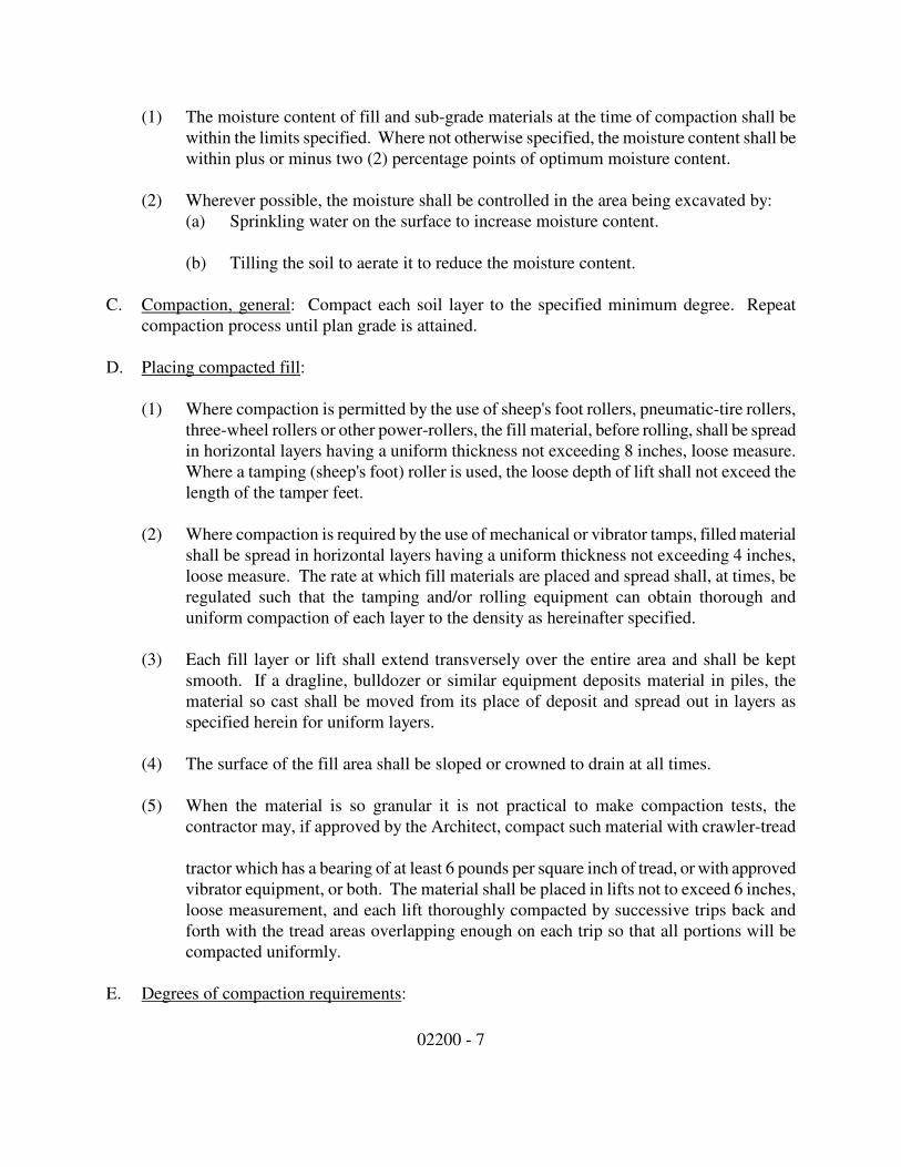
02200 - 7
(1) The moisture content of fill and sub-grade materials at the time of compaction shall be
within the limits specified. Where not otherwise specified, the moisture content shall be
within plus or minus two (2) percentage points of optimum moisture content.
(2) Wherever possible, the moisture shall be controlled in the area being excavated by:
(a) Sprinkling water on the surface to increase moisture content.
(b) Tilling the soil to aerate it to reduce the moisture content.
C. Compaction, general: Compact each soil layer to the specified minimum degree. Repeat
compaction process until plan grade is attained.
D. Placing compacted fill:
(1) Where compaction is permitted by the use of sheep's foot rollers, pneumatic-tire rollers,
three-wheel rollers or other power-rollers, the fill material, before rolling, shall be spread
in horizontal layers having a uniform thickness not exceeding 8 inches, loose measure.
Where a tamping (sheep's foot) roller is used, the loose depth of lift shall not exceed the
length of the tamper feet.
(2) Where compaction is required by the use of mechanical or vibrator tamps, filled material
shall be spread in horizontal layers having a uniform thickness not exceeding 4 inches,
loose measure. The rate at which fill materials are placed and spread shall, at times, be
regulated such that the tamping and/or rolling equipment can obtain thorough and
uniform compaction of each layer to the density as hereinafter specified.
(3) Each fill layer or lift shall extend transversely over the entire area and shall be kept
smooth. If a dragline, bulldozer or similar equipment deposits material in piles, the
material so cast shall be moved from its place of deposit and spread out in layers as
specified herein for uniform layers.
(4) The surface of the fill area shall be sloped or crowned to drain at all times.
(5) When the material is so granular it is not practical to make compaction tests, the
contractor may, if approved by the Architect, compact such material with crawler-tread
tractor which has a bearing of at least 6 pounds per square inch of tread, or with approved
vibrator equipment, or both. The material shall be placed in lifts not to exceed 6 inches,
loose measurement, and each lift thoroughly compacted by successive trips back and
forth with the tread areas overlapping enough on each trip so that all portions will be
compacted uniformly.
E. Degrees of compaction requirements:
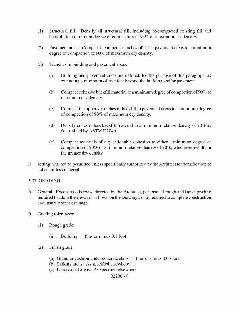
02200 - 8
(1) Structural fill: Densify all structural fill, including re-compacted existing fill and
backfill, to a minimum degree of compaction of 95% of maximum dry density.
(2) Pavement areas: Compact the upper six inches of fill in pavement areas to a minimum
degree of compaction of 90% of maximum dry density.
(3) Trenches in building and pavement areas:
(a) Building and pavement areas are defined, for the purpose of this paragraph, as
extending a minimum of five feet beyond the building and/or pavement.
(b) Compact cohesive backfill material to a minimum degree of compaction of 90% of
maximum dry density.
(c) Compact the upper six inches of backfill in pavement areas to a minimum degree
of compaction of 90% of maximum dry density.
(d) Densify cohesionless backfill material to a minimum relative density of 70% as
determined by ASTM D2049.
(e) Compact materials of a questionable cohesion to either a minimum degree of
compaction of 90% or a minimum relative density of 70%, whichever results in
the greater dry density.
F. Jetting; will not be permitted unless specifically authorized by the Architect for densification of
cohesion-less material.
3.07 GRADING
A. General: Except as otherwise directed by the Architect, perform all rough and finish grading
required to attain the elevations shown on the Drawings, or as required to complete construction
and insure proper drainage.
B. Grading tolerances:
(1) Rough grade:
(a) Building: Plus or minus 0.1 foot
(2) Finish grade:
(a) Granular cushion under concrete slabs: Plus or minus 0.05 foot
(b) Parking areas: As specified elsewhere.
(c) Landscaped areas: As specified elsewhere.
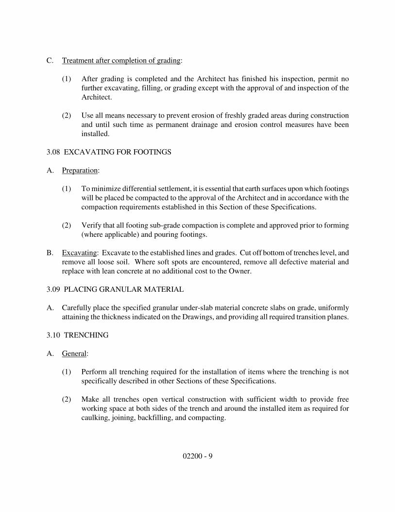
02200 - 9
C. Treatment after completion of grading:
(1) After grading is completed and the Architect has finished his inspection, permit no
further excavating, filling, or grading except with the approval of and inspection of the
Architect.
(2) Use all means necessary to prevent erosion of freshly graded areas during construction
and until such time as permanent drainage and erosion control measures have been
installed.
3.08 EXCAVATING FOR FOOTINGS
A. Preparation:
(1) To minimize differential settlement, it is essential that earth surfaces upon which footings
will be placed be compacted to the approval of the Architect and in accordance with the
compaction requirements established in this Section of these Specifications.
(2) Verify that all footing sub-grade compaction is complete and approved prior to forming
(where applicable) and pouring footings.
B. Excavating: Excavate to the established lines and grades. Cut off bottom of trenches level, and
remove all loose soil. Where soft spots are encountered, remove all defective material and
replace with lean concrete at no additional cost to the Owner.
3.09 PLACING GRANULAR MATERIAL
A. Carefully place the specified granular under-slab material concrete slabs on grade, uniformly
attaining the thickness indicated on the Drawings, and providing all required transition planes.
3.10 TRENCHING
A. General:
(1) Perform all trenching required for the installation of items where the trenching is not
specifically described in other Sections of these Specifications.
(2) Make all trenches open vertical construction with sufficient width to provide free
working space at both sides of the trench and around the installed item as required for
caulking, joining, backfilling, and compacting.
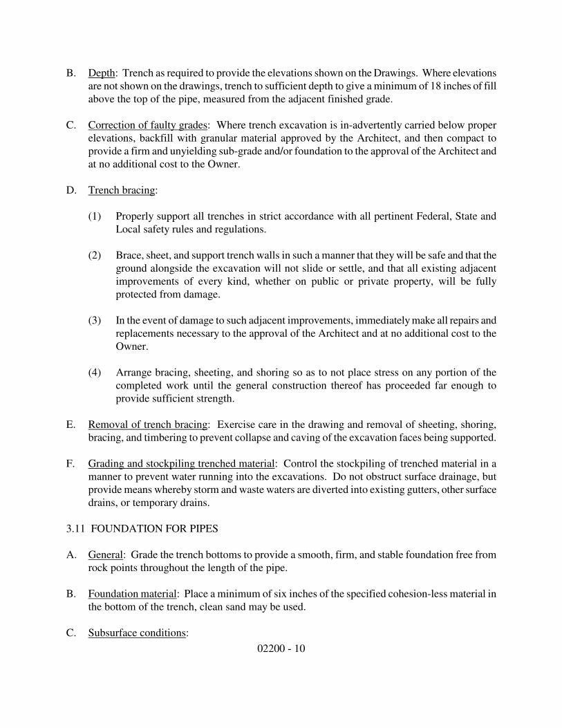
02200 - 10
B. Depth: Trench as required to provide the elevations shown on the Drawings. Where elevations
are not shown on the drawings, trench to sufficient depth to give a minimum of 18 inches of fill
above the top of the pipe, measured from the adjacent finished grade.
C. Correction of faulty grades: Where trench excavation is in-advertently carried below proper
elevations, backfill with granular material approved by the Architect, and then compact to
provide a firm and unyielding sub-grade and/or foundation to the approval of the Architect and
at no additional cost to the Owner.
D. Trench bracing:
(1) Properly support all trenches in strict accordance with all pertinent Federal, State and
Local safety rules and regulations.
(2) Brace, sheet, and support trench walls in such a manner that they will be safe and that the
ground alongside the excavation will not slide or settle, and that all existing adjacent
improvements of every kind, whether on public or private property, will be fully
protected from damage.
(3) In the event of damage to such adjacent improvements, immediately make all repairs and
replacements necessary to the approval of the Architect and at no additional cost to the
Owner.
(4) Arrange bracing, sheeting, and shoring so as to not place stress on any portion of the
completed work until the general construction thereof has proceeded far enough to
provide sufficient strength.
E. Removal of trench bracing: Exercise care in the drawing and removal of sheeting, shoring,
bracing, and timbering to prevent collapse and caving of the excavation faces being supported.
F. Grading and stockpiling trenched material: Control the stockpiling of trenched material in a
manner to prevent water running into the excavations. Do not obstruct surface drainage, but
provide means whereby storm and waste waters are diverted into existing gutters, other surface
drains, or temporary drains.
3.11 FOUNDATION FOR PIPES
A. General: Grade the trench bottoms to provide a smooth, firm, and stable foundation free from
rock points throughout the length of the pipe.
B. Foundation material: Place a minimum of six inches of the specified cohesion-less material in
the bottom of the trench, clean sand may be used.
C. Subsurface conditions:
02200 - 11
(1) In areas where soft, unstable materials are encountered at the surface upon which
cohesion-less material is to be placed, remove the unstable material and replace it with
predominantly granular material approved by the Architect. Make sufficient depth to
develop a firm foundation for the item being installed.
(2) If the need for such over-excavation has been occasioned by an act or failure to act on the
part of the Contractor, make the over-excavation and replacement at no additional cost to
the Owner.
D. Shaping:
(1) At each joint in pipe, recess the bottom of the trench as required into the firm foundation
in such a manner as to relieve the bell of the pipe of all load and to ensure continuous
bearing of the pipe barrel on the firm foundation.
(2) Accurately shape all pipe sub-grade and fit the bottom of the trench to the pipe shape.
Use a drag template shaped to conform to the outer surface of the pipe if other methods
do not produce satisfactory results.
3.12 BEDDING FOR PIPES
A. General: Place the specified cohesion-less material in six (6) inch (maximum) loose lifts,
simultaneously on each side of the pipe for the full width of the trench and hand tamp each lift,
to a minimum depth of one foot above the outside diameter of the pipe barrel.
B. Densification:
(1) Flooding and/or mass jetting shall be allowed only outside the pavement limits. Trench
fill above the pipe zone under paved areas shall be densified by wetting and
vibratory/impact machine compaction.
(2) Take special care to provide firm bedding support on the underside of the pipe and
fittings for the full length of the pipe.
C. Alternate bedding: Other bedding procedures and materials may be used if prior approval has
been obtained from the Architect.
3.13 BACKFILL FOR PIPES
A. Using on-site materials: After the pipe has been thoroughly bedded and covered, spread the on-
site material in uniform lifts of not more than eight inches in uncompacted thickness, and then
compact as specified in this Section. Repeat the spreading and compacting procedure until
adjacent grade level is attained.
02200 - 12
B. Using imported cohesion-less material: After the pipe has been thoroughly bedded and
covered, fill the remaining portion of the trench with the specified cohesion-less material, and
density as specified in this Section.
3.14 WASTE MATERIAL DISPOSAL
A. Disposal of excavated material: Except as hereinafter provided, excavated material shall,
insofar as practicable, and if suitable, be used in embankment and fill or at such other places
within the construction limits as may be specified or directed, depending on the nature of the
material. No useable material shall be wasted without authority. The Contractor shall provide
the Architect with written approval from a landowner on whose land waste material is to be
disposed.
B. If more material is excavated from within required cut slope lines than is needed to construction
embankment of fill, the excess may be used, when directed by the Architect, to widen
embankment, or flatten fill slopes, or both, or be otherwise disposed.
C. Disposing of organic material: All brush, limbs, tops and other debris resulting from the
clearing, or such material may be reduced to chips by processing through a brush chipping
machine; when a brush chipping machine is used, the chips shall be disposed of outside the
limits of the project site, or stored for future use as mulching material in a manner approved by
the Architect.
D. Disposing of inorganic material: Materials excavated or removed during the construction of the
project shall become the property of the Contractor unless otherwise shown on the plans or
specifications. Materials reserved for use shall be removed and stored outside the limits of
construction at the location and in the manner approved by the Architect. Materials that
become the property of the Contractor shall be removed from the project before acceptance of
the project.
E. Rubble:
(1) All concrete, stone, brick and other materials which have been broken into pieces such
that the largest face is not greater than 1 square foot in area and which have no salvage
value shall be placed in designated embankments in parallel layers. All voids shall be
completely filled with sound earth and compacted to the specified density. Such rubble
material shall not be placed closer than 12 inches to the sub-grade.
(2) Pieces of suitable size rubble may be used in the construction of riprap, tree wells, and
similar structures, or may be used otherwise as approved by the Architect.
3.15 SPECIAL STRUCTURAL REQUIREMENTS
02200 - 13
A. Structures with special requirements are all buildings, manholes, storm-water catch basins,
valve vaults and boxes, culvert headwalls, diversion chambers and similar structures located in
the graded areas of the site.
B. Time for curing and completing structure:
(1) Backfill against concrete walls will not be permitted prior to the expiration of the
specified curing time applicable to the latest concrete placed in the completed wall and in
no case earlier than seven days following the completion of concrete placement. Backfill
against concrete walls of a design such that horizontal support for the wall is provided by
slabs, struts, or other structural systems located near the top of the wall shall not be
started until after the slabs, struts, or other structural systems are completed.
(2) Backfill against unit masonry walls shall in no case be placed earlier than 48 hors after
the masonry is completed. In cases where the masonry wall is to receive horizontal
support from structural systems at the top of the wall, backfill operations shall not be
started prior to completion of the structural system.
(3) Walls of any types, or other parts of the structure, damaged or showing excessive
displacement as a result of the backfilling operation, shall be repaired or removed and
rebuilt as directed by the Architect. Such work ordered repaired or removed and rebuilt
shall be performed by the Contractor without additional cost to the Owner.
C. Backfill preparation: After forms for concrete masonry have been removed and after the
surface of the concrete has been prepared to receive backfill; after unit masonry construction
below grade is completed; after damp-proofing of walls, if required, is completed; after below
grade utility lines have been installed, inspected and approved, and all specified tests have been
performed, and all other work required to be performed prior to backfilling is completed, the
excavation shall be cleaned of all waste concrete, spills from masonry units, lumber, sticks and
other deleterious substances and then be backfilled as herein specified.
3.16 FIELD TESTING
A. Unless specified otherwise, the Contractor shall coordinate with the owner's testing lab the
following field density tests to insure required densities are being obtained as specified. Initial
required testing will be paid by the owner.
(1) One test for each 10,000 square feet or fraction thereof per lift of general fill.
(2) Two tests for each 10,000 square feet or fraction thereof per lift of structural fill under
slabs, foundations and pavements.
(3) One test per lift for each other type of fill, if so directed by the Architect.

02200 - 14
B. Compaction effort: At the beginning of compaction of each type of material by a specific piece
of equipment, the minimum number of passes shall be determined to meet the specified
densities, as witnessed by the Architect. The minimum required number of machine passes
determined shall be considered only a working guideline and shall in no way relieve the
contractor of his responsibility for providing the specified density in the compacted fill.
C. Conditions for acceptance of compacted fill:
(1) Each lift of fill material shall be placed, compacted, and tested for in-place density as
herein specified and shall be approved by the Architect, or the Architect's agent on site,
prior to placement of the next overlying lift of fill material.
(2) Compacted fill shall be considered acceptable provided that all of the following
conditions are met.
(a) At least two (2) in-place density tests conducted on the lift indicate specified
compaction for each test on the lift indicating less than specified compaction.
(b) Not more than 20% of all in-place density tests conducted on the completed fill, or
any single lift therein, shall indicate less than the specified degree of compaction.
(c) No in-place density test on an acceptable lift of fill shall indicate density of more
than 3% below the specified percentage of maximum density required.
(d) There are no isolated areas of soft yielding fill within the area of the lift, or portion
thereof, as determined visually by the Architect, or the Architect's agent, or the
inspector on site.
(3) Any lift of fill material, or portion thereof, failing to meet the above criteria shall be re-
compacted, removed and replaced, or otherwise treated by the Contractor to produce the
specified in-place density as herein defined at no additional cost to the Owner, including
testing.
(4) All reworked areas of fill shall be retested for in-place density and approved prior to
placement of the next overlying lift of fill material. The Architect shall reserve the right
to retest any area of questionable compaction and the contractor shall provide such
testing at no additional cost to the Owner.
D. Sub-grade compaction: Compaction of natural in-place sub-grade material under footings,
slabs, etc. shall be approved based upon in-place density test results and in accordance with the
same acceptability criterion as specified above for compacted fill.
End of Section
02281 - 1
Section 02281
TERMITE CONTROL
PART ONE - GENERAL
1.01 WORK INCLUDED
A. Soil treatment below slabs-on-grade for subterranean insects.
B. Soil treatment at interior and exterior foundation perimeter, for subterranean insects.
1.02 QUALITY ASSURANCE
A. Applicator: Company specializing in soil treatment for termite control with three (3) years
documented experience.
B. Materials: Provide certification that toxicants conform to specified requirements.
C. Material packaging: Manufacturer's labels and seals identifying content.
1.03 REGULATORY REQUIREMENTS
A. Conform to State of Indiana requirements for application licensing.
B. Indicate toxicants to be used, composition by percentage, dilution schedule, and intended
application rate.
C. Submit manufacturer's installation instructions.
1.04 PROJECT RECORD DOCUMENTS
A. Submit documents.
B. Accurately record moisture content of soil before treatment, date and rate of application, areas
of application, diary of meter readings and corresponding soil coverage.
1.05 WARRANTY
A. Provide five (5) year bonded guaranty for material and installation.
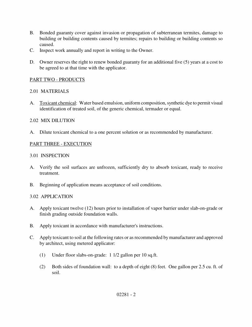
02281 - 2
B. Bonded guaranty cover against invasion or propagation of subterranean termites, damage to
building or building contents caused by termites; repairs to building or building contents so
caused.
C. Inspect work annually and report in writing to the Owner.
D. Owner reserves the right to renew bonded guaranty for an additional five (5) years at a cost to
be agreed to at that time with the applicator.
PART TWO - PRODUCTS
2.01 MATERIALS
A. Toxicant chemical: Water based emulsion, uniform composition, synthetic dye to permit visual
identification of treated soil, of the generic chemical, termader or equal.
2.02 MIX DILUTION
A. Dilute toxicant chemical to a one percent solution or as recommended by manufacturer.
PART THREE - EXECUTION
3.01 INSPECTION
A. Verify the soil surfaces are unfrozen, sufficiently dry to absorb toxicant, ready to receive
treatment.
B. Beginning of application means acceptance of soil conditions.
3.02 APPLICATION
A. Apply toxicant twelve (12) hours prior to installation of vapor barrier under slab-on-grade or
finish grading outside foundation walls.
B. Apply toxicant in accordance with manufacturer's instructions.
C. Apply toxicant to soil at the following rates or as recommended by manufacturer and approved
by architect, using metered applicator:
(1) Under floor slabs-on-grade: 1 1/2 gallon per 10 sq.ft.
(2) Both sides of foundation wall: to a depth of eight (8) feet. One gallon per 2.5 cu. ft. of
soil.
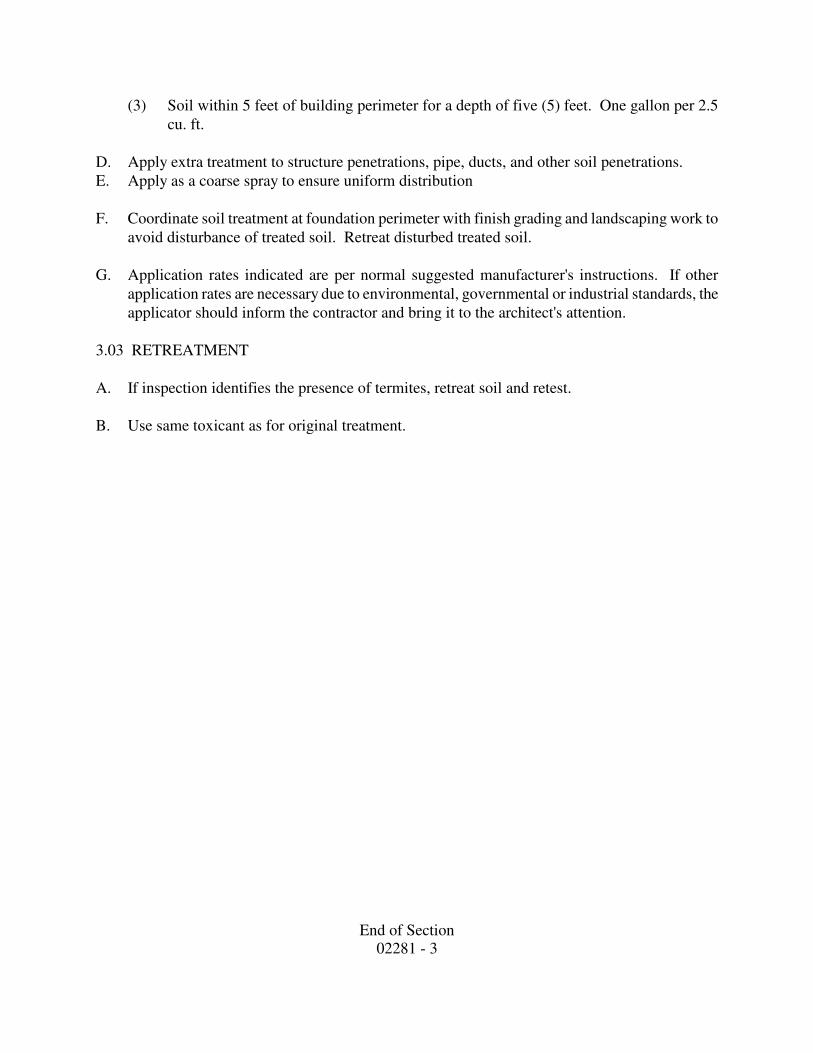
End of Section
02281 - 3
(3) Soil within 5 feet of building perimeter for a depth of five (5) feet. One gallon per 2.5
cu. ft.
D. Apply extra treatment to structure penetrations, pipe, ducts, and other soil penetrations.
E. Apply as a coarse spray to ensure uniform distribution
F. Coordinate soil treatment at foundation perimeter with finish grading and landscaping work to
avoid disturbance of treated soil. Retreat disturbed treated soil.
G. Application rates indicated are per normal suggested manufacturer's instructions. If other
application rates are necessary due to environmental, governmental or industrial standards, the
applicator should inform the contractor and bring it to the architect's attention.
3.03 RETREATMENT
A. If inspection identifies the presence of termites, retreat soil and retest.
B. Use same toxicant as for original treatment.

02520 - 1
SECTION 02520
ASPHALTIC PAVING AND SURFACING
PART ONE - GENERAL
1.01 WORK INCLUDED
A. The Contractor shall furnish all material, equipment, tools, and labor necessary to contract and
test all paving and surfacing work as specified and as shown on the Drawings and includes, but
not necessarily limited to:
(1) Existing paving removal;
(2) Mineral aggregate base course;
(3) Asphalt surfacing materials;
(4) Placing asphaltic concrete;
(5) Flood test;
(6) Parking stall stripes, and painting of handicapped symbols.
1.02 RELATED WORK SPECIFIED ELSEWHERE
A. Excavating, Filling, and Grading Section 02200
1.03 SUBMITTALS
A. Certifications:
(1) Submit certifications from plant producing bituminous mixtures that binder course and
surface course meet specified standards.
1.04 REFERENCE STANDARDS
A. Indiana State Highway standard specifications, adopted 1978, referred herein as the "STD.
SPECS."
1.05 CONFLICTS
A. In the event of any conflicts between the Contract Documents and Referenced Standard
Requirements the more stringent, higher cost and quality requirement shall be included in the
Bid.
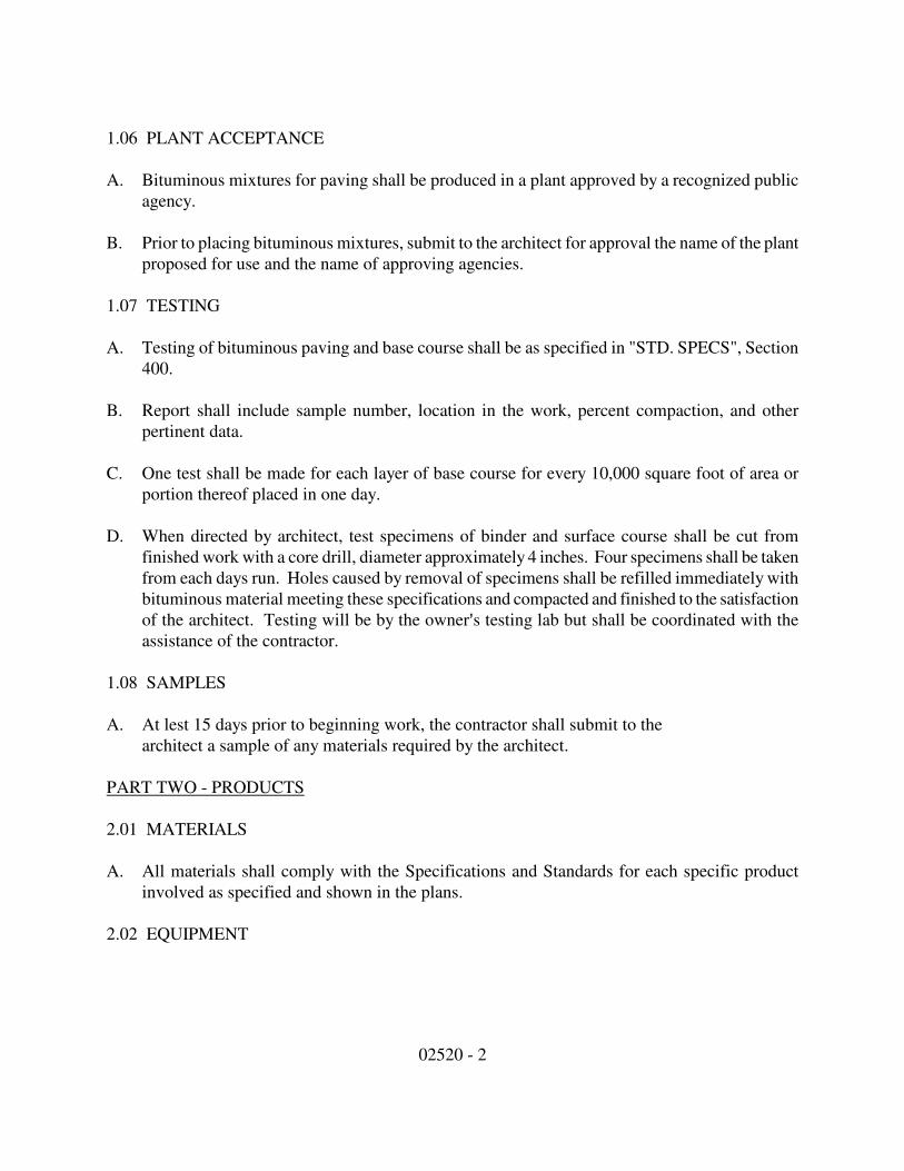
02520 - 2
1.06 PLANT ACCEPTANCE
A. Bituminous mixtures for paving shall be produced in a plant approved by a recognized public
agency.
B. Prior to placing bituminous mixtures, submit to the architect for approval the name of the plant
proposed for use and the name of approving agencies.
1.07 TESTING
A. Testing of bituminous paving and base course shall be as specified in "STD. SPECS", Section
400.
B. Report shall include sample number, location in the work, percent compaction, and other
pertinent data.
C. One test shall be made for each layer of base course for every 10,000 square foot of area or
portion thereof placed in one day.
D. When directed by architect, test specimens of binder and surface course shall be cut from
finished work with a core drill, diameter approximately 4 inches. Four specimens shall be taken
from each days run. Holes caused by removal of specimens shall be refilled immediately with
bituminous material meeting these specifications and compacted and finished to the satisfaction
of the architect. Testing will be by the owner=s testing lab but shall be coordinated with the
assistance of the contractor.
1.08 SAMPLES
A. At lest 15 days prior to beginning work, the contractor shall submit to the
architect a sample of any materials required by the architect.
PART TWO - PRODUCTS
2.01 MATERIALS
A. All materials shall comply with the Specifications and Standards for each specific product
involved as specified and shown in the plans.
2.02 EQUIPMENT

02520 - 3
A. Compacting equipment shall be self propelled tandem rollers having a minimum weight of ten
tons, except that hand-held vibrator compactors may be used in areas not accessible to rollers
when specially approved by the Architect.
B. Paving equipment shall be spreading, self propelled asphalt paving machines capable of
maintaining line, grade, and the minimum surface thickness specified.
C. All other equipment used shall be of the type and size that meet all the requirements specified
by the "STD. SPECS."
2.03 SUBGRADE MATERIALS
A. All earthwork is specified elsewhere in Division 2.
2.04 COARSE AGGREGATE
A. Coarse aggregates shall conform to the applicable provisions of "STD. SPECS", Section 903.20
and shall be of gradation No. 53 and No. 2.
2.05 PRIMER
A. Primer shall conform to grade as set forth in Section 408 of the "STD. SPECS."
2.06 BINDER COURSE MATERIALS
A. Aggregates and mineral fillers shall be dried and materials thoroughly mixed in correct
proportions with bituminous to produce a homogenous in which liquid asphalt is distributed
uniformly throughout the mixture.
B. Bituminous material shall conform to the applicable provisions of "STD. SPECS", Section 400
and shall be asphalt cement, grade AC 85-100 conforming to article 402 or 403.
2.07 SURFACE COURSE MATERIAL
A. Aggregate shall be of crushed stone or crushed gravel or sand free from adherent films. Surface
course mixture shall be graded to conform to Class A or B Article 903.02 or the "STD.
SPECS."
B. Bituminous material shall conform to the applicable provisions of "STD. SPECS", Section 400
and shall be asphalt cement, grade HC85-100.
2.08 OTHER MATERIALS
A. All other materials not specifically described but required for proper and complete
installation of the work in this Section, shall be as selected by the contractor subject to the approval
of the architect.

02520 - 4
PART THREE - EXECUTION
3.01 Preparation of the sub-grade for paving shall comply with applicable portions of Section 207 of
the "STD. SPECS."
3.02 PREPARATION
A. Contractor is to verify all dimensions, lengths, and elevations required to complete the work.
Damaged areas from operations shall be graded and seeds as indicated elsewhere in the
Specifications.
3.03 BITUMINOUS PAVING
A. Bituminous paving shall consist of aggregate base and bituminous surfacing of thickness
indicated on the drawings.
B. Base course shall be No. 53 Indiana Lime Stone placed in two 4" lifts and shall conform to
applicable provisions of Section 303, "Compacted Aggregate Base."
END OF SECTION
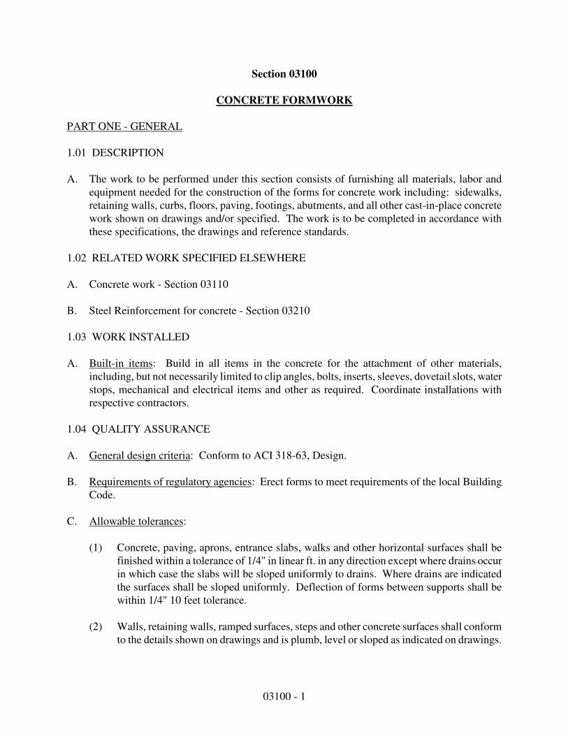
03100 - 1
Section 03100
CONCRETE FORMWORK
PART ONE - GENERAL
1.01 DESCRIPTION
A. The work to be performed under this section consists of furnishing all materials, labor and
equipment needed for the construction of the forms for concrete work including: sidewalks,
retaining walls, curbs, floors, paving, footings, abutments, and all other cast-in-place concrete
work shown on drawings and/or specified. The work is to be completed in accordance with
these specifications, the drawings and reference standards.
1.02 RELATED WORK SPECIFIED ELSEWHERE
A. Concrete work - Section 03110
B. Steel Reinforcement for concrete - Section 03210
1.03 WORK INSTALLED
A. Built-in items: Build in all items in the concrete for the attachment of other materials,
including, but not necessarily limited to clip angles, bolts, inserts, sleeves, dovetail slots, water
stops, mechanical and electrical items and other as required. Coordinate installations with
respective contractors.
1.04 QUALITY ASSURANCE
A. General design criteria: Conform to ACI 318-63, Design.
B. Requirements of regulatory agencies: Erect forms to meet requirements of the local Building
Code.
C. Allowable tolerances:
(1) Concrete, paving, aprons, entrance slabs, walks and other horizontal surfaces shall be
finished within a tolerance of 1/4" in linear ft. in any direction except where drains occur
in which case the slabs will be sloped uniformly to drains. Where drains are indicated
the surfaces shall be sloped uniformly. Deflection of forms between supports shall be
within 1/4" 10 feet tolerance.
(2) Walls, retaining walls, ramped surfaces, steps and other concrete surfaces shall conform
to the details shown on drawings and is plumb, level or sloped as indicated on drawings.
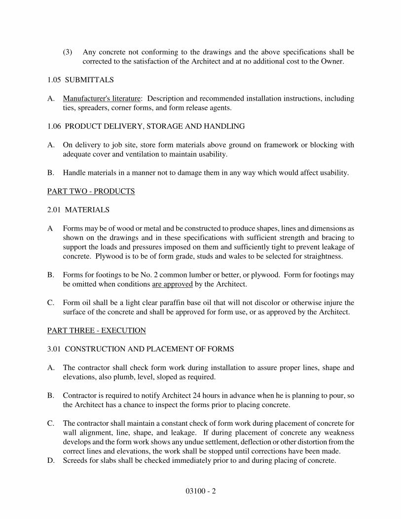
03100 - 2
(3) Any concrete not conforming to the drawings and the above specifications shall be
corrected to the satisfaction of the Architect and at no additional cost to the Owner.
1.05 SUBMITTALS
A. Manufacturer's literature: Description and recommended installation instructions, including
ties, spreaders, corner forms, and form release agents.
1.06 PRODUCT DELIVERY, STORAGE AND HANDLING
A. On delivery to job site, store form materials above ground on framework or blocking with
adequate cover and ventilation to maintain usability.
B. Handle materials in a manner not to damage them in any way which would affect usability.
PART TWO - PRODUCTS
2.01 MATERIALS
A Forms may be of wood or metal and be constructed to produce shapes, lines and dimensions as
shown on the drawings and in these specifications with sufficient strength and bracing to
support the loads and pressures imposed on them and sufficiently tight to prevent leakage of
concrete. Plywood is to be of form grade, studs and wales to be selected for straightness.
B. Forms for footings to be No. 2 common lumber or better, or plywood. Form for footings may
be omitted when conditions are approved by the Architect.
C. Form oil shall be a light clear paraffin base oil that will not discolor or otherwise injure the
surface of the concrete and shall be approved for form use, or as approved by the Architect.
PART THREE - EXECUTION
3.01 CONSTRUCTION AND PLACEMENT OF FORMS
A. The contractor shall check form work during installation to assure proper lines, shape and
elevations, also plumb, level, sloped as required.
B. Contractor is required to notify Architect 24 hours in advance when he is planning to pour, so
the Architect has a chance to inspect the forms prior to placing concrete.
C. The contractor shall maintain a constant check of form work during placement of concrete for
wall alignment, line, shape, and leakage. If during placement of concrete any weakness
develops and the form work shows any undue settlement, deflection or other distortion from the
correct lines and elevations, the work shall be stopped until corrections have been made.
D. Screeds for slabs shall be checked immediately prior to and during placing of concrete.

End of Section
03100 - 3
E. Form oil shall be applied, before the placement of reinforcing steel, and at the manufacturer's
recommended rate of application with any excess wiped off.
3.02 REMOVAL OF FORMS
A. Form work shall be removed in such a manner as to insure the complete safety of the structure.
Forms for walls and other members not supporting the weight of the concrete may be removed
after 24 hours provided the concrete is hardened sufficiently to resist damage from removal
operations.
B. Any cracks or other damage resulting from the removal of forms shall be corrected as directed
by the Architect.
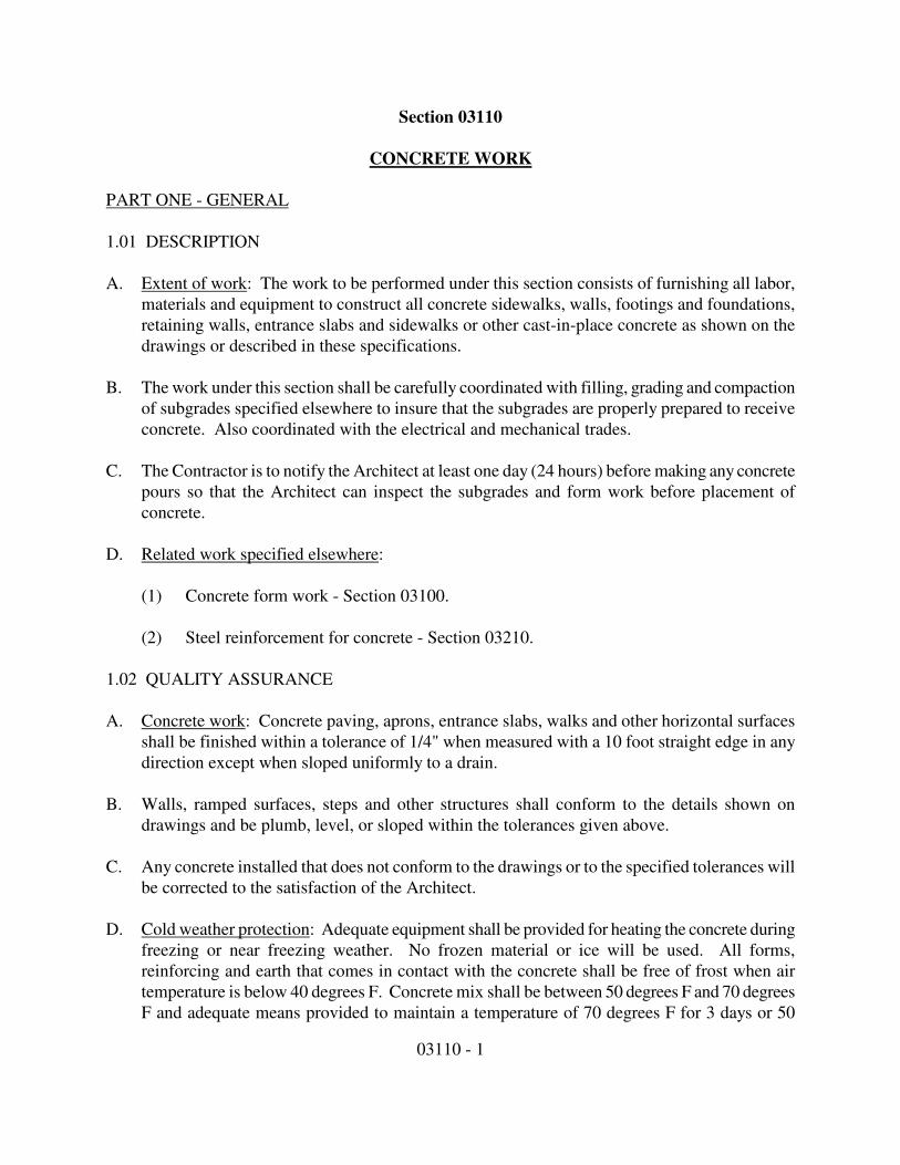
03110 - 1
Section 03110
CONCRETE WORK
PART ONE - GENERAL
1.01 DESCRIPTION
A. Extent of work: The work to be performed under this section consists of furnishing all labor,
materials and equipment to construct all concrete sidewalks, walls, footings and foundations,
retaining walls, entrance slabs and sidewalks or other cast-in-place concrete as shown on the
drawings or described in these specifications.
B. The work under this section shall be carefully coordinated with filling, grading and compaction
of subgrades specified elsewhere to insure that the subgrades are properly prepared to receive
concrete. Also coordinated with the electrical and mechanical trades.
C. The Contractor is to notify the Architect at least one day (24 hours) before making any concrete
pours so that the Architect can inspect the subgrades and form work before placement of
concrete.
D. Related work specified elsewhere:
(1) Concrete form work - Section 03100.
(2) Steel reinforcement for concrete - Section 03210.
1.02 QUALITY ASSURANCE
A. Concrete work: Concrete paving, aprons, entrance slabs, walks and other horizontal surfaces
shall be finished within a tolerance of 1/4" when measured with a 10 foot straight edge in any
direction except when sloped uniformly to a drain.
B. Walls, ramped surfaces, steps and other structures shall conform to the details shown on
drawings and be plumb, level, or sloped within the tolerances given above.
C. Any concrete installed that does not conform to the drawings or to the specified tolerances will
be corrected to the satisfaction of the Architect.
D. Cold weather protection: Adequate equipment shall be provided for heating the concrete during
freezing or near freezing weather. No frozen material or ice will be used. All forms,
reinforcing and earth that comes in contact with the concrete shall be free of frost when air
temperature is below 40 degrees F. Concrete mix shall be between 50 degrees F and 70 degrees
F and adequate means provided to maintain a temperature of 70 degrees F for 3 days or 50

03110 - 2
degrees F for five days or as much additional time as needed to insure proper protection and
curing of the concrete. The covering or shelter is to remain in place 24 hours after heating is
discontinued. Use of Calcium Chloride, salt or other chemicals will not be allowed.
E. Hot weather requirements:
(1) Concrete placed in hot weather shall have a placing temperature which will not cause
difficulty in loss of slump, flash set, or cold joints. During hot weather the Contractor
shall take adequate precautions to reduce the detrimental effects of these conditions.
(2) Forms, subgrades and reinforcement shall be sprinkled with cool water just prior to
placement of the concrete, and the area around the work shall be wetted down to cool the
surrounding air and to increase its humidity.
(3) Concrete shall be placed and finished as speedily as possible and ample personnel shall
be available to accomplish this. All tools, equipment and materials needed for the
screeding, working and curing of the concrete shall be on site prior to the need for them.
1.03 STANDARD SPECIFICATIONS
A. The ACI Publication "Standards and Code Requirements for Concrete and Reinforced
Concrete", latest edition shall govern all concrete work except as otherwise specified herein.
PART TWO - PRODUCTS
2.01 CONCRETE MATERIALS
A. All materials, unless otherwise indicated, noted or specified, shall conform to the latest edition
of the standard specification of the American Society for Testing Materials covering the
material being used.
B. All exterior concrete shall be air entrained 6% to 7%. Air entrainment shall be provided by the
use of air entrainment Portland Cement Type 1-A conforming to ASTM Designation 175, or
may be provided by the use of an air entrainment admixture conforming to the requirements of
ASTM Specification for Air Entrainment Admixtures for Concrete, Designation C260.
C. Aggregate for all concrete shall be regular stone conforming to ASTM C33.
D. Sand shall be thoroughly washed and shall be free from loam, soft stone, or other ingredients
which would affect the strength of the concrete. Sand shall be well graded from course to fine
with course particles predominating, but containing no grains which will not pass through a
1/4" mesh. ASTM C33.
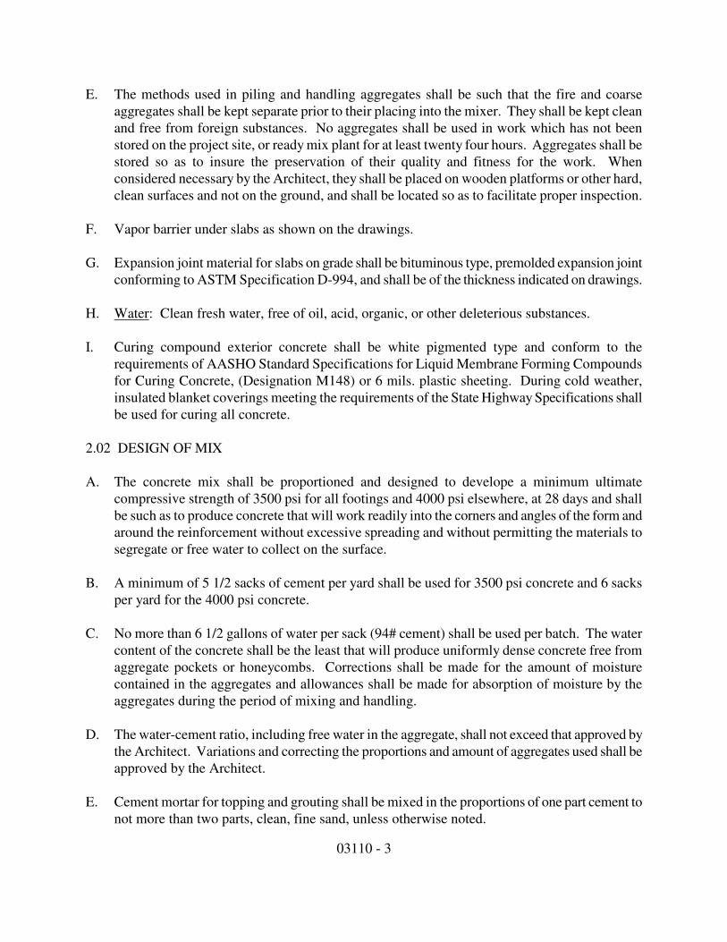
03110 - 3
E. The methods used in piling and handling aggregates shall be such that the fire and coarse
aggregates shall be kept separate prior to their placing into the mixer. They shall be kept clean
and free from foreign substances. No aggregates shall be used in work which has not been
stored on the project site, or ready mix plant for at least twenty four hours. Aggregates shall be
stored so as to insure the preservation of their quality and fitness for the work. When
considered necessary by the Architect, they shall be placed on wooden platforms or other hard,
clean surfaces and not on the ground, and shall be located so as to facilitate proper inspection.
F. Vapor barrier under slabs as shown on the drawings.
G. Expansion joint material for slabs on grade shall be bituminous type, premolded expansion joint
conforming to ASTM Specification D-994, and shall be of the thickness indicated on drawings.
H. Water: Clean fresh water, free of oil, acid, organic, or other deleterious substances.
I. Curing compound exterior concrete shall be white pigmented type and conform to the
requirements of AASHO Standard Specifications for Liquid Membrane Forming Compounds
for Curing Concrete, (Designation M148) or 6 mils. plastic sheeting. During cold weather,
insulated blanket coverings meeting the requirements of the State Highway Specifications shall
be used for curing all concrete.
2.02 DESIGN OF MIX
A. The concrete mix shall be proportioned and designed to develope a minimum ultimate
compressive strength of 3500 psi for all footings and 4000 psi elsewhere, at 28 days and shall
be such as to produce concrete that will work readily into the corners and angles of the form and
around the reinforcement without excessive spreading and without permitting the materials to
segregate or free water to collect on the surface.
B. A minimum of 5 1/2 sacks of cement per yard shall be used for 3500 psi concrete and 6 sacks
per yard for the 4000 psi concrete.
C. No more than 6 1/2 gallons of water per sack (94# cement) shall be used per batch. The water
content of the concrete shall be the least that will produce uniformly dense concrete free from
aggregate pockets or honeycombs. Corrections shall be made for the amount of moisture
contained in the aggregates and allowances shall be made for absorption of moisture by the
aggregates during the period of mixing and handling.
D. The water-cement ratio, including free water in the aggregate, shall not exceed that approved by
the Architect. Variations and correcting the proportions and amount of aggregates used shall be
approved by the Architect.
E. Cement mortar for topping and grouting shall be mixed in the proportions of one part cement to
not more than two parts, clean, fine sand, unless otherwise noted.

03110 - 4
F. The proportions herein specified for mixing of concrete shall not be varied except as may be
found necessary to meet the test requirements herein specified and then only on the instructions
of the Architect.
2.03 AFFIDAVITS ON MATERIALS
A. If requested by the Owner, the Contractor shall obtain from the various materials suppliers
notarized affidavits that the materials meet the ASTM and AASHO Specifications and other
standards referred to above, as applicable to each type of material.
PART THREE - EXECUTION
A. Plant mix concrete: If plant mix or mixed-in-transit concrete is used, each shipment shall be
accomplished by duplicate certificates, showing analysis of the mix, it shall be produced in.
B. Job mix concrete:
(1) If concrete is prepared at the site, it shall be mixed in a standard type of mechanical batch
mixer that mixes one complete batch at a time, which is entirely discharged before
another is introduced.
(2) The concrete shall be mixed to the desired consistency and until the mass is uniform in
color and homogeneous.
(3) The mixing shall continue for at least one (1) minute after all ingredients are in the
mixer.
(4) During the period of mixing, the drum shall operate at the speed for which it was
designed, except that the peripheral speed of the drum shall not be less than 175 nor more
than 225 ft. per minute.
(5) If this procedure does not effect a thorough mixing of the concrete, an additional number
of turns at the same rate of speed shall be given until a thorough mixing of each mix of
concrete is secured. The entire contents of the mixer shall be removed from the drum
before material for the succeeding batch is placed therein and the mixer shall preferably
be equipped with mechanical means for preventing the addition of aggregate or water
after mixing has commenced.
(6) The mixer shall be equipped with adequate water storage and a calibrated measuring
device for accurately measuring the amount of water used in each batch. The mixer shall
be equipped with a batch meter for accurately recording the time of mixing of each batch
and also an attachment for automatically locking the discharge chute so as to prevent the
emptying of the mixer until the materials have been mixed with the specified minimum
time. No mixer shall be operated above its rate capacity, or be used which has a rated
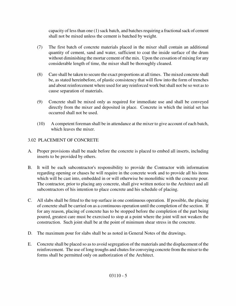
03110 - 5
capacity of less than one (1) sack batch, and batches requiring a fractional sack of cement
shall not be mixed unless the cement is batched by weight.
(7) The first batch of concrete materials placed in the mixer shall contain an additional
quantity of cement, sand and water, sufficient to coat the inside surface of the drum
without diminishing the mortar cement of the mix. Upon the cessation of mixing for any
considerable length of time, the mixer shall be thoroughly cleaned.
(8) Care shall be taken to secure the exact proportions at all times. The mixed concrete shall
be, as stated hereinbefore, of plastic consistency that will flow into the form of trenches
and about reinforcement where used for any reinforced work but shall not be so wet as to
cause separation of materials.
(9) Concrete shall be mixed only as required for immediate use and shall be conveyed
directly from the mixer and deposited in place. Concrete in which the initial set has
occurred shall not be used.
(10) A competent foreman shall be in attendance at the mixer to give account of each batch,
which leaves the mixer.
3.02 PLACEMENT OF CONCRETE
A. Proper provisions shall be made before the concrete is placed to embed all inserts, including
inserts to be provided by others.
B. It will be each subcontractor's responsibility to provide the Contractor with information
regarding opening or chases he will require in the concrete work and to provide all his items
which will be cast into, embedded in or will otherwise be monolithic with the concrete pour.
The contractor, prior to placing any concrete, shall give written notice to the Architect and all
subcontractors of his intention to place concrete and his schedule of placing.
C. All slabs shall be fitted to the top surface in one continuous operation. If possible, the placing
of concrete shall be carried on as a continuous operation until the completion of the section. If
for any reason, placing of concrete has to be stopped before the completion of the part being
poured, greatest care must be exercised to stop at a point where the joint will not weaken the
construction. Such joint shall be at the point of minimum shear stress in the concrete.
D. The maximum pour for slabs shall be as noted in General Notes of the drawings.
E. Concrete shall be placed so as to avoid segregation of the materials and the displacement of the
reinforcement. The use of long troughs and chutes for conveying concrete from the mixer to the
forms shall be permitted only on authorization of the Architect.
03110 - 6
F. All chutes, troughs, etc. shall be kept clean and free from coatings of hardened concrete by
flushing with water after each run; water used for flushing shall be discharged clear of the
concrete already in place.
G. Concrete shall not be permitted to drop freely more than five (5) feet and it will not be
permissible to allow concrete to run or be taken to fill each part of the form by depositing the
concrete as near final position as possible. The coarse aggregates shall be worked back from
the forms and the concrete forced around the reinforcement without displacing bars. Concrete
shall not be permitted to flow under runways or other obstructions that make spading
impossible.
H. Concrete shall be spaded and puddled with proper tools into compact homogeneous mass.
I. The concrete shall be placed as rapidly, continuously and in as large areas as possible, or until
the unit of operation as previously approved has been compacted. In any given operation the
batches shall be placed so that each shall be installed and compacted before the preceding one
has taken its initial set, so that perfect joining will be effected without marked indication of the
finished faces of concrete.
J. The Contractor shall keep a capable mechanic on the job during the placement of concrete to
keep reinforcement in proper alignment and spacing.
K. Insert asphalt strips of sufficient width against all masonry where cement work is installed, to
protect masonry while concrete is being placed.
3.03 MECHANICAL VIBRATION
A. The concrete shall be compacted by means of mechanical vibrator operated within the mass of
concrete.
B. Vibration shall be supplemented by hand spading. The concrete shall be spaded by hand in all
corners and angles of the forms and along all form faces as elsewhere herein specified. The
concrete shall be vibrated with a frequency of not less than 7000 impulses per minute, the
vibration shall be of sufficient intensity and duration to cause flow or settlement into place and
complete compaction. Care must be exercised that concrete is not over-vibrated, particularly if
it is of relatively wet consistency exceeding 4" in slump and that vibrators are not used to
transport concrete in the forms. Vibrators should be inserted and withdrawn at many points
from 18" to 30" apart for short periods, usually from 5 to 15 seconds is sufficient, in preference
to insertion for longer periods at wider intervals. Systematic spacing of insertions of the
vibrator should be established to insure that no concrete is missed. Vibration shall be applied to
the mass at the point of deposit and in the body of freshly deposited concrete.
03110 - 7
C. The mechanical vibrator shall be of a type and design approved by the Architect. It should be
adequately powered and capable of transmitting vibrations of the required frequency to the
concrete.
D. The vibrator shall be applied to the concrete immediately after deposit and so manipulated that
the concrete is reduced to a uniform plastic mass thoroughly compacted. It should be
thoroughly compacted around the reinforcement and worked into the corners and angles of the
forms. The vibrators shall not be attached to the forms or the reinforcement nor shall it be
placed on reinforcing steel.
E. Concrete shall be placed in layers of uniform thickness and the apparatus so operated that the
vibrating element does not penetrate through the layers of fresh concrete and disturb partially
hardened concrete in lower layers. Vibrators shall not be pushed into the mass of concrete too
rapidly and should be withdrawn slowly.
3.04 REMOVAL OF DEFECTIVE CONCRETE
A. After forms have been removed any concrete not formed as indicated on drawings, or out of
plumb, level, or alignment, or otherwise out of required tolerances shall be removed and
replaced at no additional expense to the Owner.
3.05 BONDING NEW CONCRETE TO HARDENED CONCRETE
A. Before depositing new concrete against concrete which has hardened, the surface of the
hardened concrete shall be picked and wire brushed clean to remove foreign matter, loose
particles, and laitance. The hardened concrete shall then be dampened with water and
thoroughly covered with a coat of neat cement mortar of similar proportions of the mortar in the
concrete. The fresh concrete shall be placed before the mortar has taken its initial set.
3.06 RETEMPERING
A. Concrete shall be mixed and delivered in such quantities as are required for immediate use, and
shall be placed while fresh, before losses of slump occurs. When concrete arrives at the site
with slump below that suitable for placing, water may be added only if neither the maximum
slump is exceeded or the water cement ratio is exceeded. Any water added shall be
incorporated by additional mixing equal to at least one-half of the total mixing required. Driver
is to note on delivery tickets the amount of water added and additional mixing.
3.07 CONTROL JOINTS
A. Provide control joints at the locations indicated on the drawings. The joints shall be formed as
detailed and shall be at least one-fourth of slab depth. Contraction joints shall be formed to
straight lines. Edges of slabs and those where edging is shown on the drawings shall be

03110 - 8
rounded with a radius not larger than 1/8". Construction joints shall conform to the details
shown on the drawings.
3.08 EXPANSION JOINTS
A. Expansion joints shall be installed at the locations shown on the drawings. Expansion joints in
the walks shall be installed at approximately 25 linear foot intervals. The joint material shall be
placed the full depth of slabs and flush with the top surface. All expansion joints and edges of
concrete shall be jointed and edged in accordance with customary practice. Reinforcing shall
not extend through expansion joints.
3.09 VAPOR BARRIER
A. The vapor barrier previously specified and shown on the drawings shall consist of a 6 mil.
thickness of "polyethylene sheeting" lapped not less than 6" and sealed at edges with an
adhesive as recommended by the manufacturer of the vapor barrier.
3.10 FINISHING WALLS
A. All interior exposed concrete shall have all fins and projections removed and the rough surface
produced by this operation shall be rubbed smooth. All depressions shall be filled with mortar
of the same proportions as the mortar of the same proportions as the mortar used in the body of
the concrete and this mortar shall be smoothed with a wooden float. This work shall be done
closely following removal of the forms. All exposed surfaces in finished and unfinished rooms
shall be left clean and smooth and shall present a neat and finished appearance.
B. Concrete which has a total area of honeycombed surfaces in excess of one percent of the total
surface area of the forms used for any member of the pour in which the honeycombing is
present will not be accepted and must be entirely removed and new concrete substituted by the
contractor at his own expense. Work of other Contractors adjacent to or incorporated in the
concrete to be removed shall be removed and replace protected, and repaired to the satisfaction
of the Architect at the general contractor's expense.
C. Honeycomb surfaces, for the purpose of enforcing this specification, are hereby defined as the
concrete surfaces, next to forms, in which there are voids between the particles of course
aggregate.
D. The small amount of honeycomb permitted to remain shall be filled with mortar of the same
consistency as the mortar used in the body of the concrete and smoothed with a wooden float,
closely following removal of forms. The Architect shall stop the removal of forms unless the
requirements of this section are carried out. Tops of walls shall be floated smooth. The
Contractor shall also perform any other operations in addition to those specified herein that may
be required to produce the results specified.
E. All exterior exposed walls shall be given the following treatment: Prepare a grout of about the
proportions of one part cement to one part fine sand. Grout shall be of the consistency that will
permit its application to vertical surfaces with a stiff bristle brush. The grout shall be brushed
and floated on the previously dampened concrete. Allow grout to remain on wall until the
cement has partially set, then remove excess grout with a steel trowel. After drying for an hour
or longer, depending on weather conditions, rub the wall vigorously with burlap to completely
clean the grout from the surface leaving pits filled, but there shall not be a visible film of grout
on the surface. To lighten up the surface, replace part of the grey cement with approximately
30% of white cement. Rubbing up a lather with a carborundum stone shall not be permitted.
3.11 FINISHING FLOORS
A. Immediately following the pour, the concrete shall be screeded off to bring the top surface to
proper contour and elevations. Floors, unless otherwise noted, shall be held perfectly level.
Where drains occur or slope is indicated, they shall be pitched toward drain or in direction
indicated on drawings.
B. Soon after screeding and while the concrete is still plastic, the surface shall be floated with
wood or metal floats and brought to a high grade.
C. Floor shall be steel troweled to a smooth and perfect surface after the concrete has hardened
enough so that water and fine material are not worked to the surface.
D. Do not trowel while concrete is too soft or plastic, as this will result in a less wear-resistant
surface.
E. No walking or wheeling shall be permitted on the concrete floors until concrete is thoroughly
set.
F. Floors shall be protected until final completion of the job. Any rough places which develop
shall be machine ground before any covering is applied.
G. Excess water shall be screeded off and the surfaces left clean and level.
H. In placing depressed slabs, forms shall be provided for forming the edges of depressed sections.
These shall be accurately placed with breaks located as directed.
3.12 FINISHING EXTERIOR WORK
A. Steps and walks shall have a broom finish which shall be done after the concrete is hard enough
so that it will retain the scoring.
B. Concrete drives, concrete platforms, etc. shall be finished in the following manner.

03110 - 10
(1) As soon as water has risen to the surface, it shall be floated and then troweled to a
smooth and perfect surface. As soon as concrete has set sufficiently to be firm, remove
the forms from the riser and steps, and remove all fins, ridges, etc. from the surface.
3.13 PROTECTION
A. All concrete shall be properly protected from damage during construction. No vehicles or
equipment shall be permitted on paved areas during the curing period. The Contractor shall
keep on the job an adequate supply of waterproof paper of polyethylene sheeting, or the types
previously specified, for protection of concrete surfaces from damage by rains (or snow) that
may occur during finishing operations.
3.14 OPENING TO TRAFFIC
A. Upon completion of the specified 7 day curing period, the Contractor shall removal any
coverings and other debris. No vehicles or construction equipment shall be permitted on the
paved surfaces for at least 14 days after the concrete has been placed. The areas may be opened
to light vehicular traffic and the Contractor shall be solely responsible for any cracks or other
damage resulting from vehicles or construction equipment.
3.15 TESTING
A. The contractor shall assist the owner's testing laboratory in taking concrete test. The cost of the
initial tests will be paid by the owner.
END OF SECTION

03210 - 1
Section 03210
STEEL REINFORCEMENT FOR CONCRETE
PART ONE - GENERAL
1.01 DESCRIPTION
A. The work to be performed under this section consists of furnishing all labor, materials, and
equipment required for the steel reinforcing of all concrete construction as shown on the
drawings.
B. Related work described elsewhere includes:
(1) Concrete form work Section 03100
(2) Concrete work Section 03110
1.02 PRODUCT DELIVERY AND STORAGE
A. Deliver steel reinforcing to site in bundles with tags indicating bar size and length.
B. All reinforcing when stored on site is to be on skids or platforms above ground surface and
protected from mechanical damage and corrosion.
C. Deliver and store welding electrodes in accordance with AWS D 12.1.
PART TWO - PRODUCTS
2.01 MATERIAL, GENERAL
A. Reinforcing steel for concrete work shall conform to ASTM A15 specifications for Billet Steel
Bars for concrete reinforcement, Intermediate Grade, with 40,000 psi minimum yield point.
Sizes as shown on drawings.
B. Wire mesh for concrete reinforcement shall be of types and sizes shown on the drawings, and
shall conform to the requirements of ASTM A-185 Standard Specifications for Welded Steel
Wire Fabric for Concrete Reinforcement.
C. Metal chairs, bolster, spacers, form ties, and other devices necessary for placing, spacing,
supporting, and securing reinforcement shall conform to the requirements of the Concrete
Reinforcing Steel Institute, "Manual of Standard Practice for Reinforcing Concrete
03210 - 2
Construction". Form ties shall be of a type that when forms are removed no metal remains
within 1 inch of the surface.
PART THREE - EXECUTION
3.01 GENERAL
A. Installation of steel bar reinforcing: Install steel bar of the sizes shown on the drawings in the
locations shown on the drawings.
B. When lapps occur lap and weld for a sufficient length to develop tensile strength of bar, or lap
(minimum 30 bar diameter(s) and tie with wire.
C. Install all reinforcing, bar and fabric, so that no steel reinforcing comes within 1" of any
concrete surface.
D. Install welded wire fabric using chairs, bolsters, spacers, or form ties to the location shown on
the drawings.
END OF SECTION

04100 - 1
Section 04100
MORTAR
PART ONE - GENERAL
1.01 DESCRIPTION
A. Mortar shall be masonry cement mortar (patent mortar) for all masonry work. Mortar shall
consist of Portland cement patent mortar clean sand aggregate, and water.
1.02 RELATED WORK SPECIFIED ELSEWHERE
A. Masonry Accessories - Section 04150
B. Unit Masonry - Section 04200
PART TWO - PRODUCTS
2.01 MATERIALS
A. Mortar: Mortar for all masonry work shall conform to the requirements of ASTM
Specifications C 270. All mortar shall have a minimum compressive strength of 900 pounds
per square inch at 28 days after placement. Masonry cement mortar (patent mortar) such as
"Brixment" or "LoneStar" may be used if such mortar meets the requirements specified herein.
B. Aggregate: Aggregate for mortar shall conform to ASTM specifications C 144. Aggregate
shall be clean, sharp sand, free of injurious amounts of organic material.
C. Water: Water shall be clean, potable and free from deleterious amounts of organic substances
or oils, acids, salts, or other contaminants.
D. Admixtures: Calcium chloride or other admixtures shall not be used unless approved by the
Architect.
2.02 MORTAR MIXES
A. All mortar mixes shall be in the quantity as recommended by the manufacturer.
PART THREE - EXECUTION
3.01 BATCHING, TEMPERING, MIXING
04100 - 2
A. Mortar shall be carefully proportioned by the Contractor to obtain the specified strength. The
method of measuring materials for mortar shall be such that the specified proportions can be
consistently controlled. Sand shall be measured in a container having a known volume.
B. All mortars shall be machine mixed, except as otherwise noted for small batches, for a
minimum period of five minutes with the proper amount of water for the correct workability.
The mixer shall be cleaned after each batch to prevent contamination by set mortar. Mortar
shall be used as soon as practicable after mixing. Excessive retempering of mortar will be
cause for rejection. Retempering may be done on the board but no water shall be added if there
is significant stiffening
3.02 STORAGE AND PROTECTION
A. Mortar materials and sand shall be stored in such manner to prevent deterioration and intrusion
of deleterious materials. Mortar materials are to be kept dry and free of water.
END OF SECTION

04150 - 1
Section 04150
MASONRY ACCESSORIES
PART ONE - GENERAL
1.01 DESCRIPTION
A. The work covered by this Section shall include the furnishing of all labor, materials, plant,
equipment and appliances required to complete masonry accessories as shown on the Drawings
and as specified, complete, in strict accordance with this Section of the Specifications, the
Drawings, and referenced standards.
1.02 RELATED WORK SPECIFIED ELSEWHERE
A. Mortar - Section 04100
B. Unit Masonry System - Section 04200
C. Sealants and caulking - Section 07951
PART TWO - PRODUCTS
2.01 ANCHORS AND TIE SYSTEMS
A. Anchors and ties shall be zinc coated ferrous metal of the types specified. Zinc coating ASTM
A 153, Class B-1, B-2 or B-3 as applicable. Copper cladding of steel wire shall conform to the
requirements as specified for Grade 30 HS wire in ASTM B 227.
2.02 JOINT REINFORCEMENT
A. Masonry joint reinforcement shall be factory fabricated from zinc-coated cold-drawn steel wire,
ASTM A82. Reinforcement shall consist of two or more deformed longitudinal wires No. 9
gauge, weld connected with minimum No. 9 gauge cross sires, forming a truss or ladder design.
Zinc coating, ASTM A 116, Class 1, except those cross wires used for cavity wall ties, shall be
Class 3. Out-to-out spacing of longitudinal wires shall be approximately 2 inches less than the
nominal width of the block or width in which it is placed. Distance between welded contacts of
cross wires with each longitudinal wire shall not exceed 16 inches. Joint reinforcement shall be
furnished in flat sections 10 to 20 feet in length except that factory formed corner
reinforcements and other special shapes may be less in lengths.
04150 - 2
PART THREE - EXECUTION
3.01 REPLACING REINFORCEMENT
A. Masonry joint reinforcement shall be placed so that longitudinal wires are located over face-
shell mortar beds and are fully embedded in the mortar for their entire length with minimum
mortar cover of 5/8 inch on exterior side of walls and 1/2 inch at other locations.
Reinforcement at openings shall extend not less than 24 inches beyond the end of sills or lintels
or to the end of the panel, if the distance to the end of the panel is less than 24 inches.
Reinforcement shall be lapped 6 inches or more. Factory fabricated sections shall be installed
at corners and wall intersections.
B. Align all vertical cells to maintain a clean, unobstructed system of flues.
3.02 SPLICES AND REINFORCEMENT
A. Splices may be made only at such points and in such manner that the structural strength of the
member will not be reduced. Lapped slices shall provide sufficient lap to transfer the working
stress of the reinforcement by bond and shear. Minimum lap shall be 30 bar diameters. Welded
or mechanical connections shall develop the strength of the reinforcement.
3.03 GROUTING
A. Perform wall grouting as may be required and shown on drawings in strict accordance with the
provisions for highlift grouting as described in Chapter 24 of the Uniform Building Code, latest
edition. Do not grout until masonry has cured at least 24 hours. Consolidate all grout at time of
pouring by puddling with a mechanical vibrator, filling all cells of the masonry, and then
reconsolidation later by puddling before the plasticity is lost.
3.04 CONTROL JOINTS
A. Control joints shall be provided in accordance with the locations and details shown on the
Drawings, shall be constructed by using special control joint units, open end stretcher units, or
metal-sash-jamb units, and control joint key. Control joints shall extend through bond beams,
unless otherwise indicated. On the weather side of exterior walls, control joints shall be raked
out about 1/2 inch and left ready for caulking and sealing. On the exposed-to-view faces of
interior walls, control joints shall be raked to a depth of 3/8 inch and neatly tooled square and
smooth.
END OF SECTION
04200 - 1
Section 04200
UNIT MASONRY
PART ONE - GENERAL
1.01 DESCRIPTION
A. The work covered by this Section shall include the furnishing of all labor, materials,
equipments, and appliances required to complete the masonry work shown on the Drawings and
as herein specified, complete, in strict accordance with this Section of the specifications, the
Drawings, and referenced standards.
B. Scope: The work covered by this Section shall include the following:
(1) Furnishing and installing the masonry, complete.
(2) Furnishing and installing masonry ties, anchors, reinforcement and concrete, mortar, and
grout for embedding such reinforcement.
(3) Furnishing and installing masonry and precast concrete lintels, sills, coping, and other
masonry trim to be built in the masonry.
(4) Building into masonry all bolts, anchors, nailing blocks, inserts, window and door
frames, vents, conduits, and related work to be built in, including items furnished and
located by other trades or specified in other sections.
(5) Furnishing and installing any bracing, forming, and shoring in conjunction with and in
the course of constructing the masonry and not provided in other sections.
(6) Furnishing test specimens and samples of materials as specified.
(7) Cleaning the masonry and removal of surplus material and waste.
1.02 RELATED WORK SPECIFIED ELSEWHERE
A. Mortar - Section 04100
B. Masonry accessories - Section 04150
C. Sealants and caulking - Section 07951
04200 - 2
1.03 PRODUCT DELIVERY, STORAGE, AND HANDLING
A. Use all means necessary to protect masonry materials before, during, and after installation, and
to prevent the installed work and materials of all other trades that are to be incorporated into the
masonry work.
B. All masonry materials shall be stored in a dry place and be protected against intrusion of foreign
matter. Any cement, lime, or mortar containing lumps that are not easily crushed between the
fingers shall not be used in the work.
C. Sand shall be handled and stored in such as manner as to prevent segregation of the particles
and the intrusion of any foreign material.
D. All masonry units shall be stored in a shed or stock-piled above ground on platforms and
covered with waterproof tarpaulin or other approved covering. The covering shall completely
enclose the material, and be securely fastened down.
E. In the event of damage, immediately make all repairs and replacements necessary at no
additional cost to the Owner.
PART TWO - PRODUCTS
2.01 CONCRETE MASONRY UNITS
A. Concrete masonry units, as specified below, shall be of modular dimensions where available,
and shall include all closures, jamb units, headers and special spaces and sizes required to
complete the work as shown. Units shall be of the same manufacturer, composition, size, and
appearance and shall be cured by the same process. Units shall be sound and free from cracks,
chipped edges, or other defects that would interfere with their proper setting or impair the
strength, appearance or durability of the construction. Units shall be free of any deleterious
matter that will stain plaster or corrode metal, shall be adequately cured before shipment, and
shall be delivered to the job site in an air-dry condition.
(1) Hollow load bearing and light weight units: Hollow load bearing and light weight units
shall conform to Standard Specifications for Hollow Load Bearing Concrete Masonry
Units (ASTM C90-64T or latest revision thereof).
(2) Solid load bearing units: Solid load bearing units shall conform to Standard
Specification for Solid Load Bearing Concrete Masonry Units (ASTM C145).
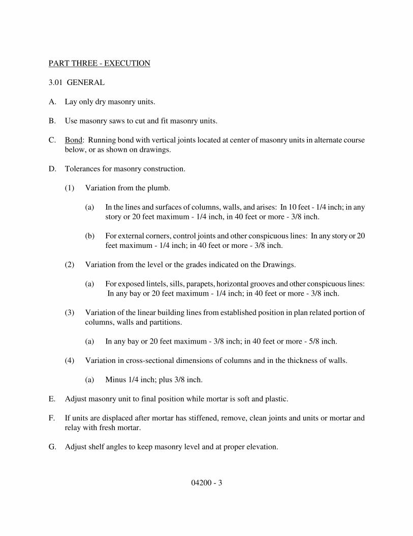
04200 - 3
PART THREE - EXECUTION
3.01 GENERAL
A. Lay only dry masonry units.
B. Use masonry saws to cut and fit masonry units.
C. Bond: Running bond with vertical joints located at center of masonry units in alternate course
below, or as shown on drawings.
D. Tolerances for masonry construction.
(1) Variation from the plumb.
(a) In the lines and surfaces of columns, walls, and arises: In 10 feet - 1/4 inch; in any
story or 20 feet maximum - 1/4 inch, in 40 feet or more - 3/8 inch.
(b) For external corners, control joints and other conspicuous lines: In any story or 20
feet maximum - 1/4 inch; in 40 feet or more - 3/8 inch.
(2) Variation from the level or the grades indicated on the Drawings.
(a) For exposed lintels, sills, parapets, horizontal grooves and other conspicuous lines:
In any bay or 20 feet maximum - 1/4 inch; in 40 feet or more - 3/8 inch.
(3) Variation of the linear building lines from established position in plan related portion of
columns, walls and partitions.
(a) In any bay or 20 feet maximum - 3/8 inch; in 40 feet or more - 5/8 inch.
(4) Variation in cross-sectional dimensions of columns and in the thickness of walls.
(a) Minus 1/4 inch; plus 3/8 inch.
E. Adjust masonry unit to final position while mortar is soft and plastic.
F. If units are displaced after mortar has stiffened, remove, clean joints and units or mortar and
relay with fresh mortar.
G. Adjust shelf angles to keep masonry level and at proper elevation.
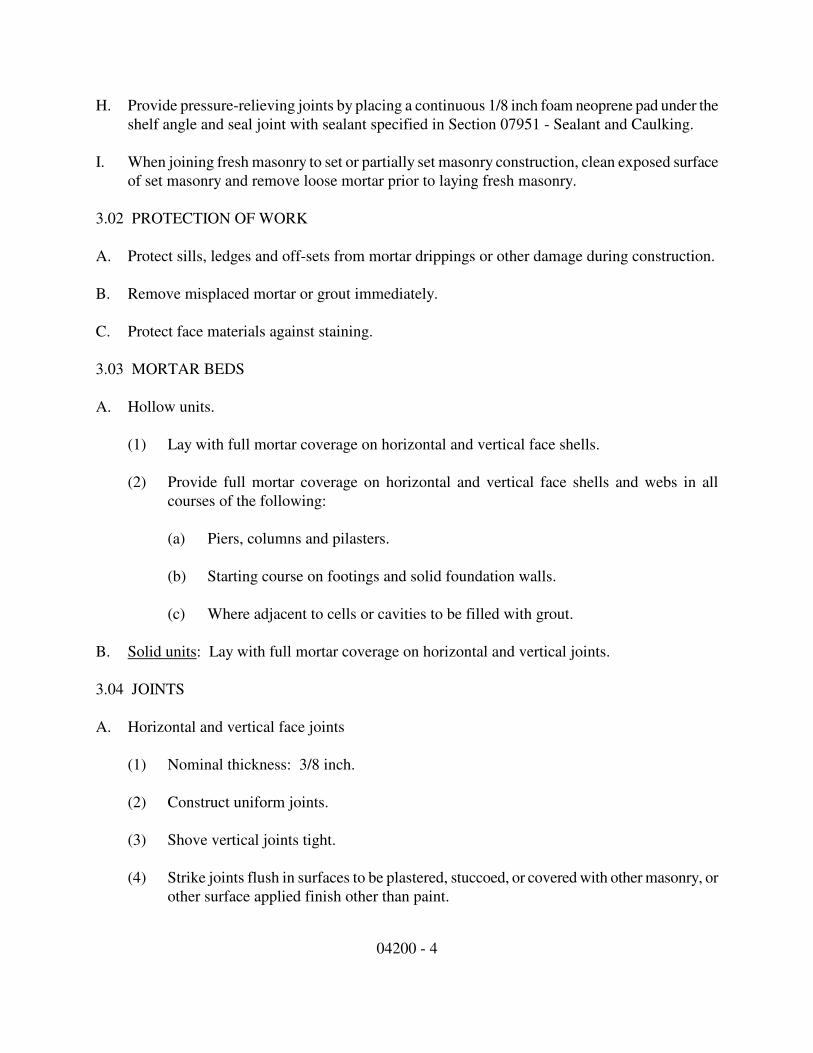
04200 - 4
H. Provide pressure-relieving joints by placing a continuous 1/8 inch foam neoprene pad under the
shelf angle and seal joint with sealant specified in Section 07951 - Sealant and Caulking.
I. When joining fresh masonry to set or partially set masonry construction, clean exposed surface
of set masonry and remove loose mortar prior to laying fresh masonry.
3.02 PROTECTION OF WORK
A. Protect sills, ledges and off-sets from mortar drippings or other damage during construction.
B. Remove misplaced mortar or grout immediately.
C. Protect face materials against staining.
3.03 MORTAR BEDS
A. Hollow units.
(1) Lay with full mortar coverage on horizontal and vertical face shells.
(2) Provide full mortar coverage on horizontal and vertical face shells and webs in all
courses of the following:
(a) Piers, columns and pilasters.
(b) Starting course on footings and solid foundation walls.
(c) Where adjacent to cells or cavities to be filled with grout.
B. Solid units: Lay with full mortar coverage on horizontal and vertical joints.
3.04 JOINTS
A. Horizontal and vertical face joints
(1) Nominal thickness: 3/8 inch.
(2) Construct uniform joints.
(3) Shove vertical joints tight.
(4) Strike joints flush in surfaces to be plastered, stuccoed, or covered with other masonry, or
other surface applied finish other than paint.
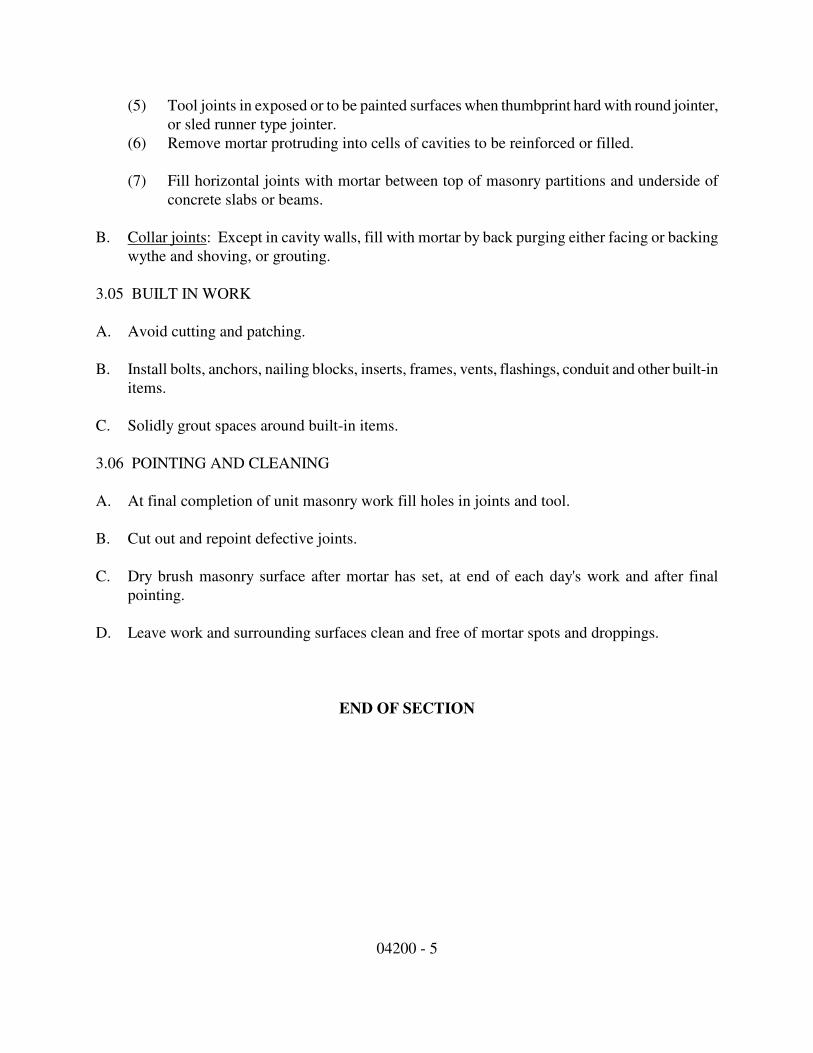
04200 - 5
(5) Tool joints in exposed or to be painted surfaces when thumbprint hard with round jointer,
or sled runner type jointer.
(6) Remove mortar protruding into cells of cavities to be reinforced or filled.
(7) Fill horizontal joints with mortar between top of masonry partitions and underside of
concrete slabs or beams.
B. Collar joints: Except in cavity walls, fill with mortar by back purging either facing or backing
wythe and shoving, or grouting.
3.05 BUILT IN WORK
A. Avoid cutting and patching.
B. Install bolts, anchors, nailing blocks, inserts, frames, vents, flashings, conduit and other built-in
items.
C. Solidly grout spaces around built-in items.
3.06 POINTING AND CLEANING
A. At final completion of unit masonry work fill holes in joints and tool.
B. Cut out and repoint defective joints.
C. Dry brush masonry surface after mortar has set, at end of each day's work and after final
pointing.
D. Leave work and surrounding surfaces clean and free of mortar spots and droppings.
END OF SECTION
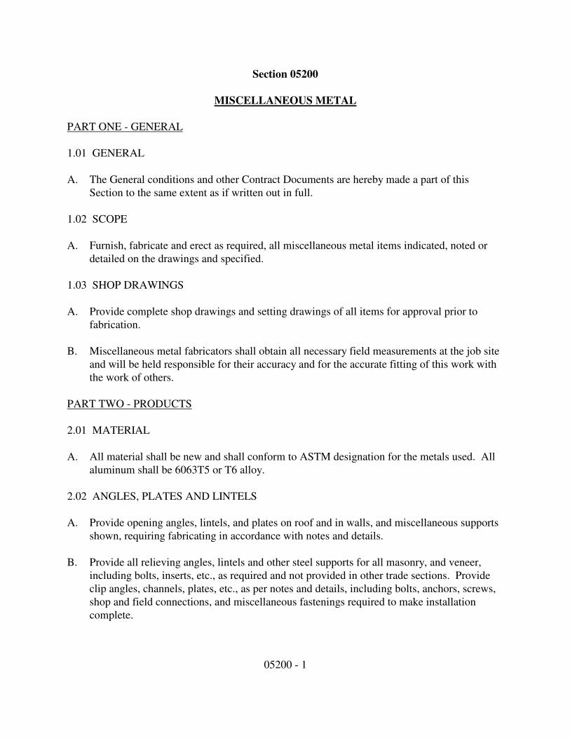
05200 - 1
Section 05200
MISCELLANEOUS METAL
PART ONE - GENERAL
1.01 GENERAL
A. The General conditions and other Contract Documents are hereby made a part of this
Section to the same extent as if written out in full.
1.02 SCOPE
A. Furnish, fabricate and erect as required, all miscellaneous metal items indicated, noted or
detailed on the drawings and specified.
1.03 SHOP DRAWINGS
A. Provide complete shop drawings and setting drawings of all items for approval prior to
fabrication.
B. Miscellaneous metal fabricators shall obtain all necessary field measurements at the job site
and will be held responsible for their accuracy and for the accurate fitting of this work with
the work of others.
PART TWO - PRODUCTS
2.01 MATERIAL
A. All material shall be new and shall conform to ASTM designation for the metals used. All
aluminum shall be 6063T5 or T6 alloy.
2.02 ANGLES, PLATES AND LINTELS
A. Provide opening angles, lintels, and plates on roof and in walls, and miscellaneous supports
shown, requiring fabricating in accordance with notes and details.
B. Provide all relieving angles, lintels and other steel supports for all masonry, and veneer,
including bolts, inserts, etc., as required and not provided in other trade sections. Provide
clip angles, channels, plates, etc., as per notes and details, including bolts, anchors, screws,
shop and field connections, and miscellaneous fastenings required to make installation
complete.

05200 - 2
PART THREE - EXECUTION
3.01 DISSIMILAR MATERIALS
A. Wherever dissimilar metals come in contact, lead or neoprene washer, spacers, gaskets, or
other approved material shall be inserted between them to provide insulation against
electrolytic action.
3.02 WORKMANSHIP
A. All work performed as per Standard Practice ACIS and National Association of
Architectural Metal Manufacturers.
B. The fabricator shall verify all dimensions of work adjoining the work hereunder. Such other
work shall be inspected before fabrication and/or installation of items specified herein.
Measurements of adjoining work shall be obtained so that work shall fit closely to spaces
provided.
C. Workmanship required in the execution of the work shall be of the best quality and subject
to the approval of the Architect.
D. The fabricator shall furnish all necessary templates and patters required by other trades. He
shall also furnish all items except as otherwise specified, pertaining to the work hereunder
that is to be built into structural work under other Sections. The erector shall supervise and
be responsible for the proper location and installation of such built-in items.
E. Metal work shall be well formed to shape and size, with sharp lines and angles. Shearing
and punching shall leave clean, true lines and surfaces. Permanent connection shall be
welded or riveted where practicable.
F. Exposed surfaces of casting shall have a smooth finish and sharp lines and arises that are
well defined. Joints shall be milled to a close fit.
G. Rivet and bolt heads shall be counter sunk flush with surface.
H. Fastenings shall be concealed where possible. Thickness of metals and details as assembling
and support shall give ample strength and stiffness. Joints exposed to the weather shall be
formed to exclude water.
I. Holes in structural steel framing for attaching miscellaneous items will be provided by the
steel fabricator if information is given in ample time by the miscellaneous metal fabricator.
05200 - 3
J. Welding shall be in accordance with current "Code for Arc and Gas Welding in Building
Construction" of the American Welding Society. Exposed welded joints shall be ground
smooth.
K. Miscellaneous metal work to be built-in shall be into masonry, concrete and/or stone work
as detailed or required, and in such cases the holes shall be carefully drilled by this
fabricator unless provided under other sections, and the work properly secured, poured with
Por-Rok, molten lead or sulphur, sealed and neatly filled and finished.
3.03 SHOP PAINTING
A. All ferrous metals shall be given one (1) shop coat of zinc chromate rust inhibitive primer
paint adaptable for light colored field painting. Wet mil thickness not less than four (4)
mils; dry, not less than two (2) mils. Field touch-up shall be done by the erector using paint
furnished by the fabricator. Finish painting will be done by the painting subcontractor.
END OF SECTION

06001 - 1
Section 06001
CARPENTRY WORK
PART ONE - GENERAL
1.01 DESCRIPTION
A. Work included: Provide all carpentry needed for a complete and proper installation as shown
on drawings, including but not necessarily limited to:
(1) Fitting and installing all wood doors and stock hollow metal doors.
(2) Provide all materials and tools necessary for a complete installation.
B. Related work described elsewhere:
(1) Interior Finish Carpentry Section 06210
(2) Cabinetwork Section 06410
(3) Solid Surface Countertops Section 06415
(3) Wood Doors and Wood Door Frame Section 08210
(4) Aluminum Clad Windows Section 08521
(6) Finish Hardware Section 08710
1.02 QUALITY ASSURANCE
A. Standards: Comply with standards specified herein and with the general requirements of the
specifications.
B. Qualifications of personnel:
(1) Throughout progress of the work of this Section, provide at least one person who shall be
thoroughly familiar with the specified requirements, completely trained and experienced
in the necessary skills and who shall be present at the site and shall direct all work
performed under this Section.
06001 - 2
(2) In actual installation of the work of this Section, use adequate numbers of skilled
workmen to ensure installation in strict accordance with the approved design and the
approved recommendation of the materials manufacturers.
1.03 SUBMITTALS
A. General: Comply with the general requirements of these specifications. Submit the
following product data for approval after aware of the contract.
(1) Manufacturer's specifications and other data to demonstrate compliance with the
specifications.
(2) Samples of the full range of colors and patterns and of exposed accessories from
proposed manufacturers.
(3) Manufacturer's recommended installation procedures, material list and shop drawings
indicating seam locations and structure.
1.04 PRODUCT HANDLING
A. Protection:
(1) Use all means necessary to protect lumber materials before, during and after delivery to
the job site, and to protect the installed work and materials of all other trades.
(2) Deliver the materials to the job site and store, all in a safe area, out of the way of traffic,
and shored up off the ground surface.
(3) Identify all framing lumber as to grades, and store all grades separately from other grades.
Ensure proper ventilation and protect from moisture and humidity.
(4) Protect all metal products with adequate waterproof outer wrappings.
(5) Use extreme care in the off-loading of lumber to prevent damage, splitting, and breaking
of materials.
B. Replacements: In the event of damage, immediately make all repairs and replacements
necessary to the approval of the Owner and at no additional cost to the Owner.
PART TWO - PRODUCTS
2.01 LUMBER AND FASTENINGS
06001 - 3
A. Framing lumber shall be Douglas Fir construction grade or SPF No. 2 or better for studs, #1
southern yellow pine for joist and rafters unless otherwise indicated on the drawings.
B. Provide fasteners properly selected for the material to be fastened and to the substrate to
which the material is to be fixed.
C. All plywood subfloor is to be 3/4" thick T&G and all roof sheathing is to be 5/8" plywood or
15/32" OSB unless otherwise indicated on drawings.
PART THREE - EXECUTION
3.01 INSPECTION
A. Examine the areas and conditions under which work of this Section will be performed.
Correct conditions detrimental to the proper and timely completion of the work. Do not
proceed until unsatisfactory conditions have been corrected.
B. Selection of lumber pieces:
(1) Carefully select all members. Select individual pieces so that knots and obvious defects
will not interfere with placing bolts or proper nailing or making connections.
(2) Cut out and discard all defects which will render a piece unable to serve its intended
function. Lumber may be rejected by the Architect, whether or not it has been installed,
for excessive warp, twist, bow, crook, mildew, fungus, or mold, as well as for improper
cutting and fitting.
(3) Shimming: Do not shim sills, joists, short studs, trimmers, headers, lintels, or other
framing components.
3.02 GENERAL FRAMING
A. General:
(1) In addition to all framing operations normal to fabrication and erection indicated on the
Drawings, install all backing required for work of other trades.
(2) Set all horizontal or sloped members with crown up.
(3) Do not notch, bore, or cut members for pipes, ducts, conduits, or other reasons except as
shown on the Drawings or as specifically approved in advance by the Architect.
06001 - 4
(4) Install all plywood subfloors with construction adhesive on joists and nailing. All beams
other than non window and service door headers shall be glued and nailed.
3.03 DELIVERIES
A. Stockpiling: Stockpile all materials sufficiently in advance of need to ensure their
availability in a timely manner for this work.
B. Delivery schedule: Make as many trips to the job site as are necessary to deliver all materials
of this Section in a timely manner to ensure orderly progress of the total work.
3.04 INSTALLATION OF OTHER FINISH HARDWARE
A. Locations: Using only the specified finish hardware, and the proper equipment for the
purpose, install all finish hardware.
B. Anchoring: Anchor all components firmly into position for long life under hard use. Use
only the anchoring devices furnished with the hardware items, unless otherwise specifically
directed.
3.05 INSPECTION, ADJUSTMENT, AND REPORTING
A. General: Using the personnel described in Paragraph 1.02B of the Section, inspect each item
of installed finish hardware. Verify that each such item has been installed in strict
accordance with the manufacturer's recommendations is in proper condition, and functions in
its intended manner.
B. Adjustment: On all finish hardware items designed to permit adjustment, submit a written
report stating:
(1) That all installed finish hardware has been inspected in accordance with Article.
(2) That all installed finish hardware is in accordance with these Specifications as to quality,
type, appearance, operation, and all other specified attributes.
(3) A precise list, by door opening number and hardware item, of all items of finish hardware
which do not meet the specified requirements in furnishing, in installation, or both.
3.06 ALIGNMENT
A. On all framing members to receive a finished wall or ceiling, align the finish subsurface to
vary not more than 1/8 inch from the plane of surfaces of adjacent framing and furring
members.
3.07 FASTENING
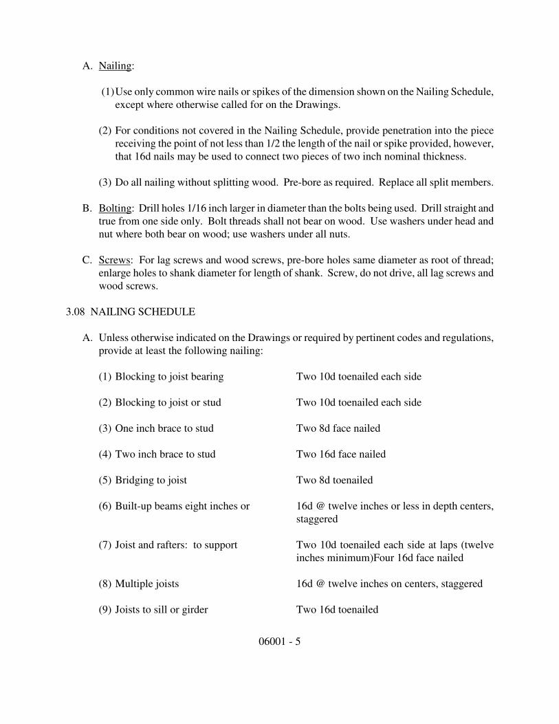
06001 - 5
A. Nailing:
(1) Use only common wire nails or spikes of the dimension shown on the Nailing Schedule,
except where otherwise called for on the Drawings.
(2) For conditions not covered in the Nailing Schedule, provide penetration into the piece
receiving the point of not less than 1/2 the length of the nail or spike provided, however,
that 16d nails may be used to connect two pieces of two inch nominal thickness.
(3) Do all nailing without splitting wood. Pre-bore as required. Replace all split members.
B. Bolting: Drill holes 1/16 inch larger in diameter than the bolts being used. Drill straight and
true from one side only. Bolt threads shall not bear on wood. Use washers under head and
nut where both bear on wood; use washers under all nuts.
C. Screws: For lag screws and wood screws, pre-bore holes same diameter as root of thread;
enlarge holes to shank diameter for length of shank. Screw, do not drive, all lag screws and
wood screws.
3.08 NAILING SCHEDULE
A. Unless otherwise indicated on the Drawings or required by pertinent codes and regulations,
provide at least the following nailing:
(1) Blocking to joist bearing Two 10d toenailed each side
(2) Blocking to joist or stud Two 10d toenailed each side
(3) One inch brace to stud Two 8d face nailed
(4) Two inch brace to stud Two 16d face nailed
(5) Bridging to joist Two 8d toenailed
(6) Built-up beams eight inches or 16d @ twelve inches or less in depth centers,
staggered
(7) Joist and rafters: to support Two 10d toenailed each side at laps (twelve
inches minimum)Four 16d face nailed
(8) Multiple joists 16d @ twelve inches on centers, staggered
(9) Joists to sill or girder Two 16d toenailed

06001 - 6
(10)One inch furring to underside Two 8d (one straight; of joists one slanted)
(11)Two inch furring to underside Two 16d (one straight; of joists one slanted)
(12)Studs toenailed to plate Two 10d each side
(13)Studs end nailed to plate Two 20d
(14)Studs nailed together 16d @ twelve inches on centers, staggered
(15)Plates: 16d @ twelve inches on centers, staggered .
At splices Two 16d face nailed. Plate lap at
corners Two 16d face nailed
3.09 CLEANING UP
A. General: Keep the premises in a neat, safe, and orderly condition at all times during execution of
this portion of the work, free from accumulation of sawdust, cut ends, and debris.
END OF SECTION
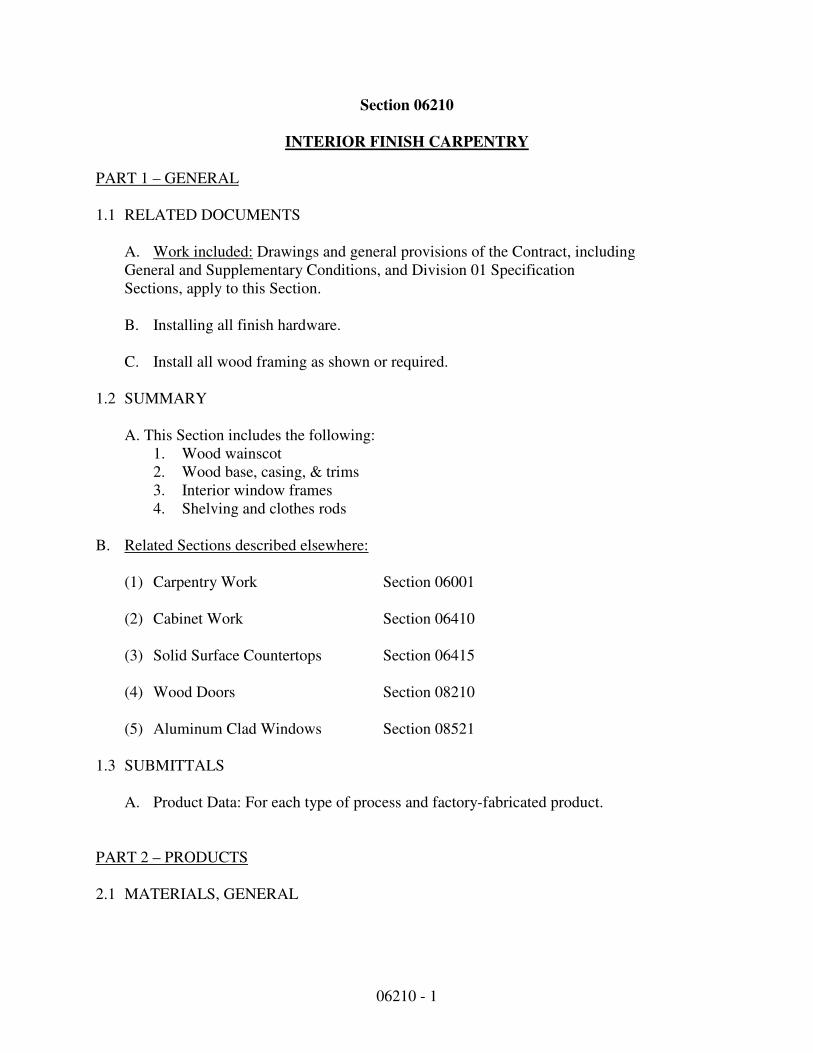
06210 - 1
Section 06210
INTERIOR FINISH CARPENTRY
PART 1 – GENERAL
1.1 RELATED DOCUMENTS
A. Work included: Drawings and general provisions of the Contract, including
General and Supplementary Conditions, and Division 01 Specification
Sections, apply to this Section.
B. Installing all finish hardware.
C. Install all wood framing as shown or required.
1.2 SUMMARY
A. This Section includes the following:
1. Wood wainscot
2. Wood base, casing, & trims
3. Interior window frames
4. Shelving and clothes rods
B. Related Sections described elsewhere:
(1) Carpentry Work Section 06001
(2) Cabinet Work Section 06410
(3) Solid Surface Countertops Section 06415
(4) Wood Doors Section 08210
(5) Aluminum Clad Windows Section 08521
1.3 SUBMITTALS
A. Product Data: For each type of process and factory-fabricated product.
PART 2 – PRODUCTS
2.1 MATERIALS, GENERAL

06210 - 2
A. Lumber: DOC PS 20 and applicable grading rules of inspection agencies
certified by ALSC's Board of Review.
B. Softwood Plywood: DOC PS 1.
C. Hardboard: AHA A135.4.
D. MDF: ANSI A208.2, Grade 130.
E. Particleboard: ANSI A208.1, Grade M-2.
F. Melamine-Faced Particleboard: Particleboard complying with ANSI A208.1,
Grade M-2, finished on both faces with thermally fused, melamine-impregnated
decorative paper complying with LMA SAT-1.25626579 06 2023-1
2.2 FIRE-RETARDANT-TREATED MATERIALS
A. Lumber: Comply with performance requirements in AWPA C20, Interior Type
Kiln dry after treatment to a maximum moisture content of 19 percent.
B. Plywood: Comply with performance requirements in AWPA C27, Interior Type
Kiln dry after treatment to a maximum moisture content of 15 percent.
C. Application: Where indicated.
2.3 STANDING AND RUNNING TRIM
A. Hardwood Lumber Trim:
1. Species and Grade: Red oak; Clear; NHLA.
2. Maximum Moisture Content: 10 percent.
B. Hardwood Moldings for Transparent Finish (Stain or Clear Finish): WMMPA
HWM 2, N-grade wood moldings made to patterns included in WMMPA WM 1
1. Species: Red oak.
2. Maximum Moisture Content: 9 percent.
2.4 SHELVING AND CLOTHES RODS
A. Shelving: Made from 3/4 inch thick melamine-faced particleboard with applied
3mm PVC front edge. Do not use particleboard or MDF that contains urea
formaldehyde.
B. Shelf Cleats: 3/4-by-3-1/2-inch boards with hole and notch to receive clothes
rods, as specified above for shelving.

06210 - 3
C. Shelf Brackets with Rod Support: BHMA A156.16, B04051; prime-painted
formed steel.
D. Shelf Brackets without Rod Support: BHMA A156.16, B04041; prime-painted
formed steel.
E. Clothes Rods: 1-1/2-inch- diameter, clear, kiln-dried hardwood.
2.5 MISCELLANEOUS MATERIALS
A. Glue: Aliphatic-resin, polyurethane, or resorcinol wood glue.
1. Use wood glue that has a VOC content of 30 g/L or less when calculated
according to 40 CFR 59, Subpart D (EPA Method 24).
PART 3 – EXECUTION
3.1 PREPARATION
A. Before installing interior finish carpentry, condition materials to average
prevailing humidity in installation areas for a minimum of 24 hours.
3.2 INSTALLATION, GENERAL
A. Install interior finish carpentry level, plumb, true, and aligned with adjacent
materials. Use concealed shims where necessary for alignment.
1. Scribe and cut interior finish carpentry to fit adjoining work.
2. Countersink fasteners, fill surface flush, and sand where face fastening is
unavoidable.
3. Install to tolerance of 1/8 inch in 96 inches for level and plumb. Install
adjoining interior finish carpentry with 1/32-inch maximum offset.
3.3 STANDING AND RUNNING TRIM INSTALLATION
A. Install with minimum number of joints practical, using full-length pieces from
maximum lengths of lumber available. Cope at returns and miter at corners to
produce tight-fitting joints. Use scarf joints for end-to-end joints.
3.4 SHELVING AND CLOTHES ROD INSTALLATION

06210 - 4
A. Cut shelf cleats at ends of shelves about 1/2 inch less than width of shelves and
sand exposed ends smooth.
B. Install shelf cleats by fastening to framing or backing with finish nails or trim
screws, set below face and filled. Space fasteners not more than 16 inches o.c.
C. Install shelf brackets according to manufacturer's written instructions, spaced not
more than 36 inches o.c. Fasten to framing members, blocking, or metal
backing, or use toggle bolts or hollow wall anchors.
D. Cut shelves to neatly fit openings with only enough gap to allow shelves to be
removed and reinstalled. Install shelves, fully seated on cleats, brackets, and
supports
3.5 INSTALLATION OF WOOD DOORS
A. Initial inspection of doors: Prior to start of installation of each door, carefully inspect the
door and verify:
(1) That the door furnished is the proper door for the opening, as described on the Door
Schedule in the Drawings.
(2) That the door is in sound condition, unblemished, without warp, twist, bow, or other
attributes causing it to be rejected upon installation.
B. Handling: Carry all doors, do not drag them. Use extreme care in handling to prevent
damage.
C. Fitting: Trim all wood doors as necessary to provide a uniform clearance of between 3
mm (1/8") and 5 mm (3/16") at jambs and head, and a uniform clearance at the threshold
or floor to properly clear the floor covering described on the Finish Schedule in the
Drawings.
D. Installing: For each door, verify the hardware type as described on the Door Schedule in
the Drawings and verify that hardware actually supplied is the hardware specified. Using
only the specified hinges or butts, and the proper equipment for the purpose, install the
door into the opening with the following hinge or butt locations throughout the work:
(1) Top hinge or butt: The center of the hinge or butt not more than 28 cm (11:) below
the top of the door;
(2) Bottom hinge or butt: The center of the hinge or butt not more than 33 cm (13")
above the finish floor;
(3) Intermediate hinge, butt, or pivot:Equidistant between the top and bottom hinge, butt,
or pivot.

06210 - 5
E. Finishing:
(1) With fine sandpaper, working only in direction of the grain of the wood, remove all
rough edges resulting from door trimming and leave the installed door in condition to
receive its final finish.
(2) Carefully touch-up all trimmed surfaces, applying a finish equal in all respects to the
factory-prefinish.
END OF SECTION

06240 - 1
Section 06240
LAMINATED PLASTIC
PART ONE-GENERAL
1.01 DESCRIPTION
A. Work included: Provide all laminated plastic, complete, in place, as shown on the
Drawings, specified, herein, and needed for a complete and proper installation.
B. Related work described elsewhere:
(1) Carpentry – Section 06001
(2) Cabinetwork – Section 06410
1.02 QUALITY ASSURANCE
A. Standards: Comply with the standards specified herein and as listed in Section 01085.
B. Qualifications of manufacturers: Products used in the work of this Section shall be
produced by manufacturers regularly engaged in manufacture of similar items and with
a history of successful production acceptable to the Architect.
1.03 SUBMITTALS
A. Product data:
(1) Within 20 calendar days after award of the Contract, submit:
(a) Complete materials list of all items proposed to be furnished and installed under
this Section.
(b) Manufacturer’s specifications and other data required to demonstrate compliance
with the specified requirements.
(c) Samples of the full range of colors and patterns available in each of the specified
grades from the proposed manufacturer.
(d) Manufacturer’s recommended installation procedures.
(2) The manufacturer’s recommended installation procedures, when approved by the
Architect, will become the basis for inspection and accepting or rejecting actual
installation procedures used on the work.
1.04 PRODUCT HANDLING
A. Protection: Use all means necessary to protect materials of the Section before, during,
and after installation and to protect the work and materials of all other trades.

06240 - 2
B. Replacement: In the event of damage, immediately make all repairs and replacements
necessary to the approval of the Architect and at no additional cost to the Owner.
PART TWO – PRODUCT
2.01 GENERAL
A. All plastic laminate shall be “general purpose”, “postforming”, or “specified purpose”
type as recommended by the Contractor and approved by the Architect for use on the
various surfaces, and shall be “high wear ARP” type finish in accordance with the
provisions of NEMA LD3.
B. Countertops are to be ¾’ thick with ¾’ front drop, unless otherwise indicated.
2.02 COLORS AND PATTERNS
A. All countertops are to be as called out on drawings.
END OF SECTION
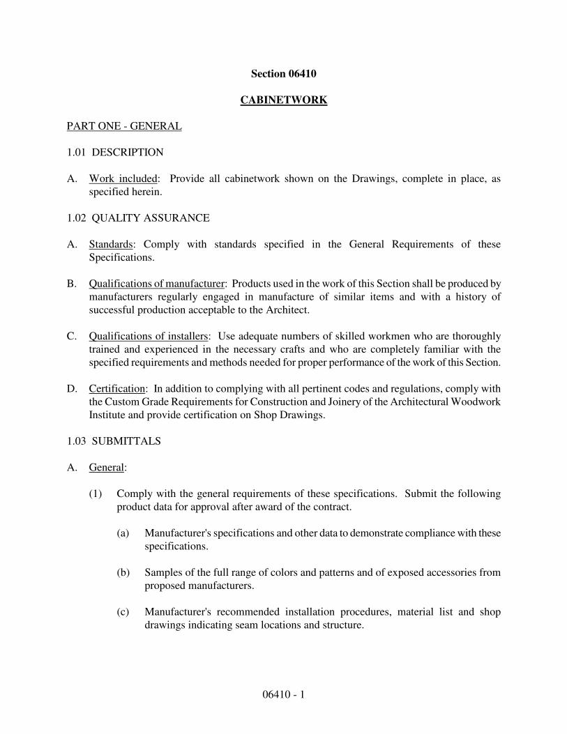
06410 - 1
Section 06410
CABINETWORK
PART ONE - GENERAL
1.01 DESCRIPTION
A. Work included: Provide all cabinetwork shown on the Drawings, complete in place, as
specified herein.
1.02 QUALITY ASSURANCE
A. Standards: Comply with standards specified in the General Requirements of these
Specifications.
B. Qualifications of manufacturer: Products used in the work of this Section shall be produced by
manufacturers regularly engaged in manufacture of similar items and with a history of
successful production acceptable to the Architect.
C. Qualifications of installers: Use adequate numbers of skilled workmen who are thoroughly
trained and experienced in the necessary crafts and who are completely familiar with the
specified requirements and methods needed for proper performance of the work of this Section.
D. Certification: In addition to complying with all pertinent codes and regulations, comply with
the Custom Grade Requirements for Construction and Joinery of the Architectural Woodwork
Institute and provide certification on Shop Drawings.
1.03 SUBMITTALS
A. General:
(1) Comply with the general requirements of these specifications. Submit the following
product data for approval after award of the contract.
(a) Manufacturer's specifications and other data to demonstrate compliance with these
specifications.
(b) Samples of the full range of colors and patterns and of exposed accessories from
proposed manufacturers.
(c) Manufacturer's recommended installation procedures, material list and shop
drawings indicating seam locations and structure.
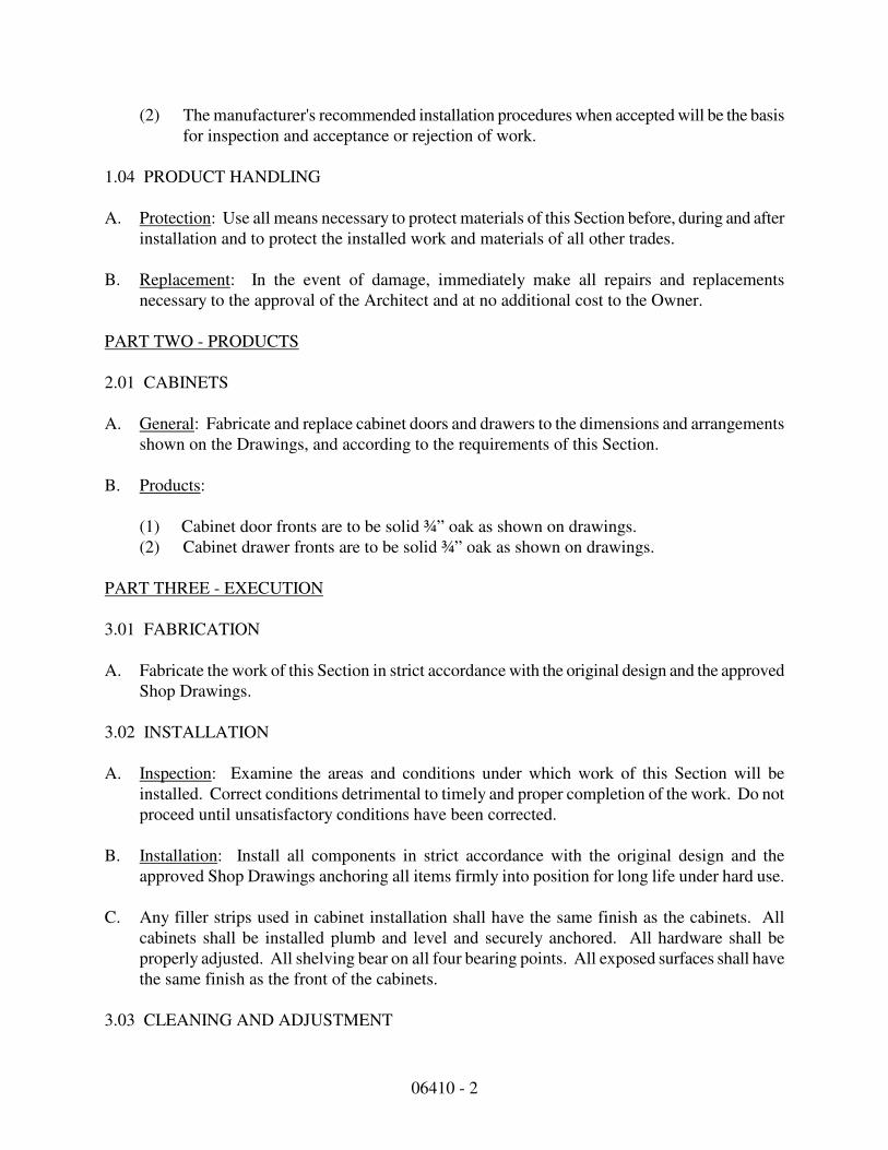
06410 - 2
(2) The manufacturer's recommended installation procedures when accepted will be the basis
for inspection and acceptance or rejection of work.
1.04 PRODUCT HANDLING
A. Protection: Use all means necessary to protect materials of this Section before, during and after
installation and to protect the installed work and materials of all other trades.
B. Replacement: In the event of damage, immediately make all repairs and replacements
necessary to the approval of the Architect and at no additional cost to the Owner.
PART TWO - PRODUCTS
2.01 CABINETS
A. General: Fabricate and replace cabinet doors and drawers to the dimensions and arrangements
shown on the Drawings, and according to the requirements of this Section.
B. Products:
(1) Cabinet door fronts are to be solid ¾” oak as shown on drawings.
(2) Cabinet drawer fronts are to be solid ¾” oak as shown on drawings.
PART THREE - EXECUTION
3.01 FABRICATION
A. Fabricate the work of this Section in strict accordance with the original design and the approved
Shop Drawings.
3.02 INSTALLATION
A. Inspection: Examine the areas and conditions under which work of this Section will be
installed. Correct conditions detrimental to timely and proper completion of the work. Do not
proceed until unsatisfactory conditions have been corrected.
B. Installation: Install all components in strict accordance with the original design and the
approved Shop Drawings anchoring all items firmly into position for long life under hard use.
C. Any filler strips used in cabinet installation shall have the same finish as the cabinets. All
cabinets shall be installed plumb and level and securely anchored. All hardware shall be
properly adjusted. All shelving bear on all four bearing points. All exposed surfaces shall have
the same finish as the front of the cabinets.
3.03 CLEANING AND ADJUSTMENT
END OF SECTION
06410 - 3
A. Upon completion of the installation, visually inspect each installed item, thoroughly clean all
surfaces by using the cleaning materials recommended by the manufacturer of the finish being
cleaned, and carefully adjust all operating components for optimum operation.

07212 - 1
Section 07212
INSULATION
PART ONE - GENERAL
1.01 DESCRIPTION
A. Extent of work: The work to be performed under this Section includes, but is not necessarily
limited to, furnishing all workers, materials, and equipment to insulate all areas and items as
shown on the Drawings, specified herein, in accordance with the General Requirements and
chosen manufacturers' directions as approved by the Architect for a complete and finished job.
(1) Wall and Ceiling Insulation
B. Coordination: The work of this Section shall be coordinated with all other crafts pertinent to an
on-schedule, finished and complete job.
1.02 QUALITY ASSURANCE
A. Standards: Comply with standards specified herein, the General Requirements and those of the
chosen manufacturers as approved by the Architect.
B. Qualifications of manufacturers: Products used in the work of this Section shall be produced by
manufacturers regularly engaged in the manufacture of similar items and with a history of
successful production acceptable to the Architect.
C. Qualification of workers: Use adequate numbers of skilled workers who are thoroughly trained
and experienced in the necessary crafts and who are completely familiar with the specified
requirements and methods needed for proper performance of the work of this Section.
1.03 SUBMITTALS
A. General: Comply with the General Requirements of these Specifications and submit the
following product data for approval after aware of the Contract:
(1) Manufacturer's specifications, installation procedures and other data to demonstrate
compliance with these specifications.
(2) The manufacturer's recommended installation procedures when accepted will become the
basis for inspection and acceptance or rejection of the work.
1.04 PRODUCT HANDLING
07212 - 2
A. Delivery and storage: Deliver materials to job site and store in their original containers or
wrappings with all labels intact and legible at time of use. Store in strict accordance with the
manufacturer's recommendations.
B. Protection: Use all means necessary to protect materials of this Section before, during, and
after installation and to protect installed work and materials of all other trades.
C. Replacement: In the event of damage, immediately make all repairs and replacements
necessary to the approval of the Architect and at no additional cost to the Owner.
PART TWO - PRODUCTS
2.01 MATERIALS
A. Ceiling Insulation shall be R-38 in ceiling of the appropriate thickness fiberglass blown in
ceilings equal to Certainteed, Johns Manville, or Owens-Corning.
B. Wall Insulation: Interior wall perimeter insulation shall be 5 1/2" minimum of fiberglass batts
with an r-value as shown on drawings.
C. Foundation Insulation shall be insulation board as shown on drawings. The insulation board
shall be rigid foundation insulation which meets the requirements of federal specification HH-I-
524C Type I.
D. Exterior Wall Vapor Barrier: All exterior frame or furred walls shall have a 6 mil vapor barrier
installed on the interior side of the wall.
E. Exterior Frame Walls Air Barrier: Tyvek or equal air barrier is required on all exterior frame
walls covered with sidings or veneers.
F. Sound Insulation: Sound insulation is to be unfaced fiberglass equal to insulation as used in B
above, unfaced batts.
PART THREE - EXECUTION
A. Wall and Ceiling: Ceiling and wall insulation shall be installed strictly following
manufacturer's directions as approved by the Architect and in accordance with the Drawings
and these Specifications.
END OF SECTION
07311-1
SECTION 07311
ASPHALT SHINGLES
PART ONE - GENERAL
1.01 DESCRIPTION
A. The work in this section shall include the furnishing and installation of asphalt shingles
as shown on the drawings and as specified herein. Installation shall include all plant,
material, equipment, and appliances required to perform installation operations.
1.02 RELATED WORK SPECIFIED ELSEWHERE
A. Flashing and Sheet Metal: Section 07620
1.03 QUALITY ASSURANCE
A. Install Asphalt shingles to meet requirements of the Manufacturer's instruction.
1.04 SUBMITTALS
A. Samples: Submit copies of GAF product data sheets, detail drawings and
samples for each type of roofing product.
1. Shingles: two of each style selected indicating full range of color.
2. Roll Roofing: two pieces, 12" x 12" indicating full range of color.
1.05 QUALITY ASSURANCE
A. Manufacturer Qualifications: Provide all primary roofing products, including
shingles, underlayment, leak barrier, and ventilation, by a single manufacturer.
B. Installer Qualifications: Installer must be approved for installation of all roofing
products to be installed under this section.
1.06 REGULATORY REQUIREMENTS
A. Provide a roofing system achieving an Underwriters Laboratories (UL) Class A
fire classification.
B. Install all roofing products in accordance with all federal, state and local building
codes.
C. All work shall be performed in a manner consistent with current OSHA
guidelines.

07311-2
1.07 PRODUCT DELIVERY, STORAGE AND HANDLING
A. Store all products in manufacturer's unopened, labeled packaging until they are
ready for installation.
B. Store products in a covered, ventilated area, at temperature not more than 110
degrees F (43 degrees C); do not store near steam pipes, radiators, or in direct
sunlight.
C. Store bundles on a flat surface. Maximum stacking height shall not exceed
manufacturer’s recommendations. Store all rolls on end.
D. Store and dispose of solvent-based materials in accordance with all federal,
state and local regulations.
1.08 WEATHER CONDITIONS
A. Proceed with work only when existing and forecasted weather conditions will
permit work to be performed in accordance with manufacturer’s recommendations
1.09 JOB CONDITIONS
A. Do not install underlayment or shingles on wet surfaces.
B. Do no apply shingles when air temperature is below 32F.
1.10 GUARANTEE
A. Materials: Guarantee against manufacturing defects for 25 years. Provide to
owner.
B. Workmanship: Guarantee against defects for 1 year. Provide to owner.
PART TWO - PRODUCTS:
2.01 MATERIALS
A. Square tab butt strip shingles.
1. ASTM D 3018 - Type I and D3161, Type I.
2. Approximate Size: 36" long x 12" wide, 5-5/8" exposure.
3. Minimum Weight: 220 lbs/sq.
4. U.L. Listed Class C self-sealing material for wind resistance.
5. Midweight, granule surfaced self sealing asphalt shingle with a strong
fiberglass reinforced Micro Weave® core and StainGuard® protection, which
prevents pronounced discoloration from blue-green algae through
formulation/unique blends of granules. Architectural laminate styling
provides a wood shake appearance with a 5 5/8 inch exposure.
07311-3
B. Asphalt shingles shall be produced by manufacturers regularly engaged in the
manufacture of similar items with a history of successful production acceptable to
the Architect and equal to limited lifetime GAF Timberline HD Shingle, color AS
NOTED ON DRAWINGS.
C. Asphalt-Saturated roofing felt: ASTM D-226 No. 30, organic, unperformed, 36"
wide.
D. Mineral surface roll roofing: ASTM D-249 matching shingles in color and texture
for valley flashing if required. (Double flash valley).
E. Smooth surface roll roofing: ASTM D-224 55 lbs., grade if required.
F. Hip and Ridge Shingles: As per manufacturer's recommended products
G. Nails: Standard round wire, zinc-coated steel or aluminum; 10 to 12 gauge,
smooth, barbed or deformed shank, with heads 3/8 inch (9mm) to 7/16 inch
(11mm) in diameter. Length must be sufficient to penetrate into solid wood at
least 3/4 inch (19mm) or through plywood or oriented strand board by at least 1/8
inch (3.18mm).
H. Bituminous Plastic Cement: FS SS-C-1538, Type I.
2.02 LEAK BARRIER
A. Self-adhering, self sealing, bituminous leak barrier surfaced with fine, skid-
resistant granules. Each roll contains approx. 150 sq ft (13.9 sq.m.), 36” X 50’ (0.9m x
20.3m) or 200 sq ft (18.6 sq.m.), 36” X 66.7’ (0.9m x 20.3m). As per manufacturer’s
recommended product.
B. Self-adhering, self sealing, bituminous leak barrier surfaced with a coated surface
and added tack for extra traction. Each roll contains approx. 200 sq ft (18.6 sq.m.), 36in.
X 66.7ft. (0.9m x 20.3m) As per manufacturer’s recommended product.
C. Self-adhering, self sealing, bituminous leak barrier surfaced with a smooth
polyethylene film. Each Roll contains approx. 200 sq ft. (18.6 sq.m.), 36” X 66.7’
(0.9m x 20.3m), and 60 mils thick. As per manufacturer’s recommended product.
D. Self-adhering air & moisture barrier film surfaced SBS modified flashing. Roll
sizes available in 7 different dimensions. As per manufacturer’s recommended
product.
2.03 SHINGLE UNDERLAYMENT
A. Water repellent, breather type cellulose/glass fiber composite roofing
underlayment. Each roll contains approximately 4 squares (432 sq. ft.) of
material and is 36” x 144” As per manufacturer’s recommended product.
B. Premium, water repellant, breather type non-asphaltic underlayment. UV
stabilized polypropylene construction. Meets or exceeds ASTM D226 and
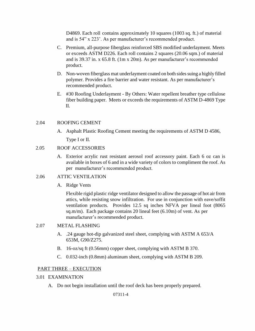
07311-4
D4869. Each roll contains approximately 10 squares (1003 sq. ft.) of material
and is 54” x 223’. As per manufacturer’s recommended product.
C. Premium, all-purpose fiberglass reinforced SBS modified underlayment. Meets
or exceeds ASTM D226. Each roll contains 2 squares (20.06 sqm.) of material
and is 39.37 in. x 65.8 ft. (1m x 20m). As per manufacturer’s recommended
product.
D. Non-woven fiberglass mat underlayment coated on both sides suing a highly filled
polymer. Provides a fire barrier and water resistant. As per manufacturer’s
recommended product.
E. #30 Roofing Underlayment - By Others: Water repellent breather type cellulose
fiber building paper. Meets or exceeds the requirements of ASTM D-4869 Type
II.
2.04 ROOFING CEMENT
A. Asphalt Plastic Roofing Cement meeting the requirements of ASTM D 4586,
Type I or II.
2.05 ROOF ACCESSORIES
A. Exterior acrylic rust resistant aerosol roof accessory paint. Each 6 oz can is
available in boxes of 6 and in a wide variety of colors to compliment the roof. As
per manufacturer’s recommended product.
2.06 ATTIC VENTILATION
A. Ridge Vents
Flexible rigid plastic ridge ventilator designed to allow the passage of hot air from
attics, while resisting snow infiltration. For use in conjunction with eave/soffit
ventilation products. Provides 12.5 sq inches NFVA per lineal foot (8065
sq.m/m). Each package contains 20 lineal feet (6.10m) of vent. As per
manufacturer’s recommended product.
2.07 METAL FLASHING
A. .24 gauge hot-dip galvanized steel sheet, complying with ASTM A 653/A
653M, G90/Z275.
B. 16-oz/sq ft (0.56mm) copper sheet, complying with ASTM B 370.
C. 0.032-inch (0.8mm) aluminum sheet, complying with ASTM B 209.
PART THREE – EXECUTION
3.01 EXAMINATION
A. Do not begin installation until the roof deck has been properly prepared.
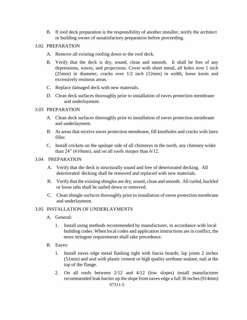
07311-5
B. If roof deck preparation is the responsibility of another installer, notify the architect
or building owner of unsatisfactory preparation before proceeding.
3.02 PREPARATION
A. Remove all existing roofing down to the roof deck.
B. Verify that the deck is dry, sound, clean and smooth. It shall be free of any
depressions, waves, and projections. Cover with sheet metal, all holes over 1 inch
(25mm) in diameter, cracks over 1/2 inch (12mm) in width, loose knots and
excessively resinous areas.
C. Replace damaged deck with new materials.
D. Clean deck surfaces thoroughly prior to installation of eaves protection membrane
and underlayment.
3.03 PREPARATION
A. Clean deck surfaces thoroughly prior to installation of eaves protection membrane
and underlayment.
B. At areas that receive eaves protection membrane, fill knotholes and cracks with latex
filler.
C. Install crickets on the upslope side of all chimneys in the north, any chimney wider
than 24” (610mm), and on all roofs steeper than 6/12.
3.04 PREPARATION
A. Verify that the deck is structurally sound and free of deteriorated decking. All
deteriorated decking shall be removed and replaced with new materials.
B. Verify that the existing shingles are dry, sound, clean and smooth. All curled, buckled
or loose tabs shall be nailed down or removed.
C. Clean shingle surfaces thoroughly prior to installation of eaves protection membrane
and underlayment.
3.05 INSTALLATION OF UNDERLAYMENTS
A. General:
1. Install using methods recommended by manufacturer, in accordance with local
building codes. When local codes and application instructions are in conflict, the
more stringent requirements shall take precedence.
B. Eaves:
1. Install eaves edge metal flashing tight with fascia boards; lap joints 2 inches
(51mm) and seal with plastic cement or high quality urethane sealant; nail at the
top of the flange.
2. On all roofs between 2/12 and 4/12 (low slopes) install manufacturer
recommended leak barrier up the slope from eaves edge a full 36 inches (914mm)

07311-6
or to at least 24 inches (610 mm) beyond the interior “warm wall”. Lap ends 6
inches (152mm) and bond.
C. Valleys:
1. Install eaves protection membrane at least 36 (914mm) inches wide and centered
on the valley. Lap ends 6 inches (152mm) and seal.
2. Where valleys are indicated to be "open valleys", install metal flashing over
manufacturer recommended leak barrier before manufacturer recommended
roof deck protection is installed; DO NOT nail through the flashing. Secure
the flashing by nailing at 18 inches (457 mm) on center just beyond edge of
flashing so that nail heads hold down the edge.
D. Hips and Ridges:
1. Install manufacturer recommended leak barrier along entire lengths. If ridge vents
are to be installed, position the manufacturer recommended leak barrier so that the
ridge slots will not be covered.
E. Roof Deck:
1. Install one layer of manufacturer recommended roof deck protection over the
entire area not protected by manufacturer recommended leak barrier at the eaves
or valley. Install sheets horizontally so water sheds and nail in place.
2. On roofs sloped at more than 4 in 12, lap horizontal edges at least 2 inches
(51mm) and at least 2 inches (51mm) over eaves protection membrane.
3. On roofs sloped between 2 in 12 and 4 in 12, lap horizontal edges at least 19
inches (482 mm) and at least 19 inches (482mm) over eaves protection membrane.
4. Lap ends at least 4 inches (102 mm). Stagger end laps of each layer at least 36
inches (914 mm).
5. Lap GAF roof deck protection over manufacturer recommended leak barrier in
valley at least 6 inches (152mm).
F. Deck-Armor™ or equal product per manufacturer’s recommendation Application
1. Deck-Armor™ shall be installed over a clean, dry deck.
2. Install manufacturer recommended leak barrier at eaves, valleys, rakes, skylights,
dormers and other vulnerable leak areas.
3. Lay Deck-Armor™ over deck and overlap 3” (76mm) at side laps and 6”
(152mm) at end laps.
4. For exposure to rain or snow, overlap 12” (305mm) at end laps.
5. For side and end laps: fasten Deck-Armor 12” (305mm) o.c.6” (152mm)o.c. for
high wind areas).
6. For middle of the roll: fasten Deck-Armor 24” (610mm) o.c.12” (305mm) o.c. for

07311-7
high wind areas).
7. For exposure to rail or snow, completely cover all side laps, end laps and fasteners
with tape.
8. For long term exposure see complete manufacturer’s installation instructions for
side lap detail.
9. If roof may be exposed to high winds, apply tape over all fasteners at the center of
the roll to prevent rain or snow from entering at the fasteners.
10. For slopes less that 2:12, a double application of Deck-Armor is required. See
complete manufacturer’s installation instructions for more information.
G. Penetrations:
1. Vent pipes: Install a 24 inch (610 mm) square piece of eaves protection membrane
lapping over roof deck underlayment; seal tightly to pipe.
2. Vertical walls: Install eaves protection membrane extending at least 6 inches
(152mm) up the wall and 12 inches (305mm) on to the roof surface. Lap the
membrane over the roof deck underlayment.
3. Rake Edges: Install metal edge flashing over eaves protection membrane and roof
deck underlayment; set tight to rake boards; lap joints at least 2 inches (51mm)
and seal with plastic cement; secure with nails.
3.06 INSTALLATION OF SHINGLES
A. General:
1. Install in accordance with manufacturer’s instructions and local building codes.
When local codes and application instructions are in conflict, the more
stringent requirements shall take precedence.
2. Minimize breakage of shingles by avoiding dropping bundles on edge, by
separating shingles carefully (not by "breaking" over ridge or bundles), and by
taking extra precautions in temperatures below 40 degrees F (4 degrees C).
3. Handle carefully in hot weather to avoid scuffing the surfacing, or damaging the
shingle edges.
B. Placement and Nailing:
1. For maximum wind resistance along rakes & eaves, install manufacturer
recommended starter strip containing sealant or cement shingles to
underlayment and each other in a 4" (102mm) width of asphalt plastic roof
cement.
2. Secure with 4, 5, or 6 nails per shingle per manufacturer’s instructions or
local codes.

07311-8
3. Placement of nails varies based on the type of shingle specified. Consult
the application instructions for the specified shingle for details.
4. Nails must be driven flush with the shingle surface. Do not overdrive or
under drive the nails.
5. Shingle offset varies based on the type of shingle specified. Consult the
application instructions for the specified shingle for details.
C. Placement and Nailing:
1. Beginning with the starter strip, trim shingles so that they “nest” within the
shingle located beneath it. This procedure will yield a first course that is
typically 3” (76mm) to 4” (102mm) rather than a fully exposed shingle.
2. For maximum wind resistance along rakes, install manufacturer
recommended starter strip containing sealant or cement shingles to
underlayment and each other in a 4" (102mm) width of asphalt plastic roof
cement.
3. Laterally, offset the new shingles from the existing keyways, to avoid waves
or depressions caused by excessive dips in the roofing materials.
4. Using the bottom of the tab on existing shingles, align subsequent courses.
5. Note: DO NOT install standard sized shingles (5” exposure) over metric (5
5/8” exposure) shingles, as it will overexpose the shingles and reveal the
nails. Use standard alignment methods to assure proper shingle placement.
6. Secure with 4, 5, or 6 nails per shingle per GAF’s instructions or local codes.
7. Placement of nails varies based on the type of shingle specified. Consult the
application instructions for the specified shingle for details.
8. Nails must be driven flush with the shingle surface. Do not overdrive or
under drive the nails.
9. Shingle offset varies based on the type of shingle specified. Consult the
application instructions for the specified shingle for details.
D. Valleys:
1. Install valleys using the "open valley" method:
a. Snap diverging chalk lines on the metal flashing, starting at 3 inches
(76mm) each side of top of valley, spreading at 1/8 inch per foot (9mm
per meter) to the eaves.
b. Run shingles to chalk line.
c. Trim last shingle in each course to match the chalk line; do not trim
shingles to less than 12 inches (305mm) wide.

07311-9
d. Apply a 2 inch (51mm) wide strip of plastic cement under ends of
shingles, sealing them to the metal flashing.
2. Install valleys using the "closed cut valley" method:
a. Run the first course of shingles from the higher roof slope across the
valley at least 12 inches (305mm).
b. Run succeeding courses of shingles from the lower roof slope across the
valley at least 12 inches (305mm) and nail not closer than 6 inches
(152mm) to center of valley.
c. Run shingles from the upper roof slope into the valley and trim 2 inches
(51mm) from the center line.
3. Install valleys using "woven valley" method:
a. Run shingles from both roof slopes at least 12 inches (305mm) across
center of valley, lapping alternate sides in a woven pattern.
b. DO NOT nail less than 6 inches (152mm) from the valley center line.
E. Penetrations
1. All Penetrations are to be flashed according to GAF, ARMA and NRCA
application instructions and construction details.
3.07 INSTALLATION OF ATTIC VENTILATION
A. General
1. Ventilation must meet or exceed current F.H.A., H.U.D. and local code
requirements.
B. Ridge / Soffit ventilation
1. Install ridge vent along the entire length of ridges:
2. Cut continuous vent slots through the sheathing, stopping 6 inches
(152mm) from each end of the ridge.
3. On roofs without ridge board, make a slot 1 inch (25mm) wide, on either
side of the peak (2” (51mm) overall).
4. On roofs with ridge board, make two slots 1-3/4 inches (44.5mm) wide,
one on each side of the peak (3 ½” (89mm) overall).
5. Install ridge vent material along the full length of the ridge, including
uncut areas.
6. Butt ends of ridge vent material and join using roofing cement.
7. Install eaves vents in sufficient quantity to equal or exceed the ridge vent
area.

07311-10
3.08 PROTECTION
A. Protect installed products from foot traffic until completion of the project.
B. Any roof areas that are not completed by the end of the workday are to be
protected from moisture and contaminants.
End of Section

07464 - 1
SECTION 07464
VINYL SIDING
PART 1 GENERAL
1.01 SECTION INCLUDES
A. Solid vinyl siding and accessories.
B. Solid vinyl soffit and accessories.
C. Vented vinyl soffit and accessories.
1.02 RELATED SECTIONS
A. Section 06001 - Carpentry
B. Section 07951 - Sealants and Caulking
1.03 REFERENCES
A. ASTM D 1435 -- Standard Practice for Outdoor Weathering of Plastics.
B. ASTM D 3679 -- Standard Specification for Rigid Poly (Vinyl Chloride) (PVC) Siding.
1.04 PERFORMANCE REQUIREMENTS
A. Provide vinyl siding and accessories that comply with requirements of ASTM D 3679,
Class 2.
(1) Cell classification: 1334.
(2) Tensile strength: 7,344 psi.
(3) Modulus of elasticity: 455,750 psi average.
(4) Izod impact, standard 1/8 inch bar: 1.5 ft.lbs/in average.
(5) Deflection temperature: 168 degrees F.
(6) Flash ignition temperature: 752 degrees F.
(7) Self ignition temperature: 842 degrees F.
(8) Maximum smoke density: 86 percent.
(9) Smoke density rating: 52.4 percent average.
(10)Flammability, horizontal:
(a) Burn distance: Less than 10 mm.
(b) Burn time: Less than 5 seconds.
(11) Flammability, vertical: Non-burning.
(12) Wind load resistance: 58.2 ft-lbs/sq. ft.
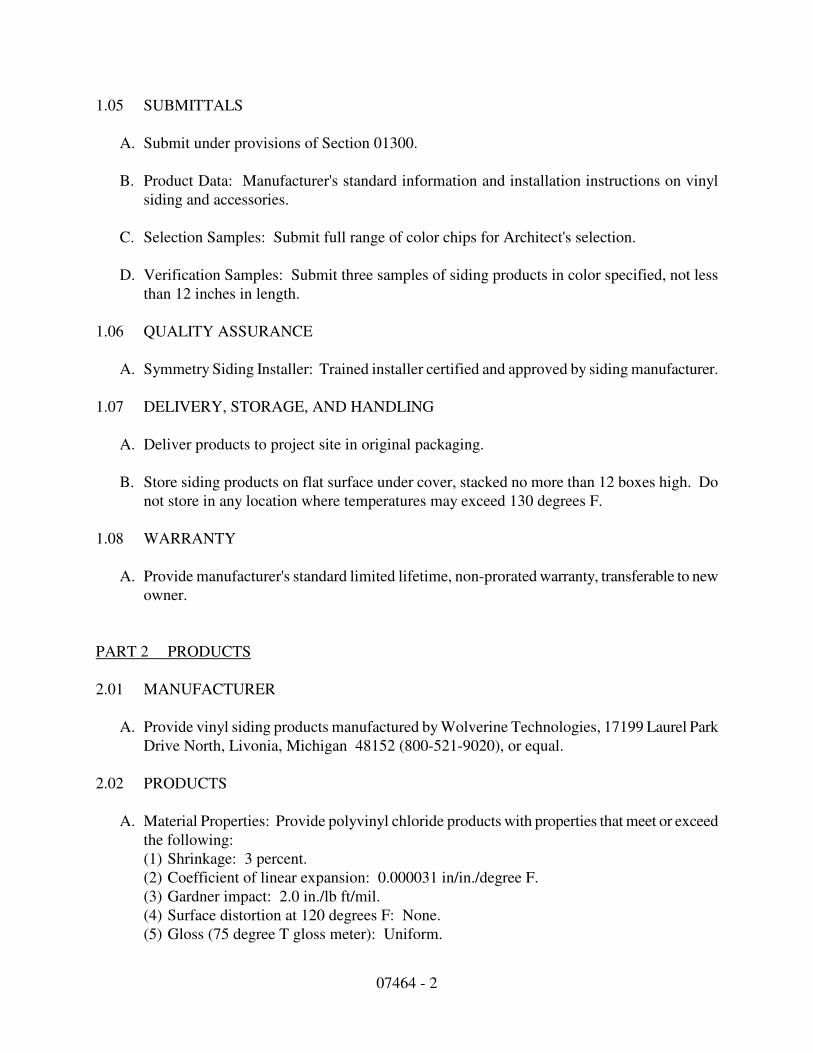
07464 - 2
1.05 SUBMITTALS
A. Submit under provisions of Section 01300.
B. Product Data: Manufacturer's standard information and installation instructions on vinyl
siding and accessories.
C. Selection Samples: Submit full range of color chips for Architect's selection.
D. Verification Samples: Submit three samples of siding products in color specified, not less
than 12 inches in length.
1.06 QUALITY ASSURANCE
A. Symmetry Siding Installer: Trained installer certified and approved by siding manufacturer.
1.07 DELIVERY, STORAGE, AND HANDLING
A. Deliver products to project site in original packaging.
B. Store siding products on flat surface under cover, stacked no more than 12 boxes high. Do
not store in any location where temperatures may exceed 130 degrees F.
1.08 WARRANTY
A. Provide manufacturer's standard limited lifetime, non-prorated warranty, transferable to new
owner.
PART 2 PRODUCTS
2.01 MANUFACTURER
A. Provide vinyl siding products manufactured by Wolverine Technologies, 17199 Laurel Park
Drive North, Livonia, Michigan 48152 (800-521-9020), or equal.
2.02 PRODUCTS
A. Material Properties: Provide polyvinyl chloride products with properties that meet or exceed
the following:
(1) Shrinkage: 3 percent.
(2) Coefficient of linear expansion: 0.000031 in/in./degree F.
(3) Gardner impact: 2.0 in./lb ft/mil.
(4) Surface distortion at 120 degrees F: None.
(5) Gloss (75 degree T gloss meter): Uniform.

07464 - 3
(6) Weathering per ASTM D 1435: Free of any visual surface defects, such as peeling,
chipping, cracking, flaking or crazing due to manufacturing conditions.
(7) Chalking: Number 6 Rating caused by manufacturing defects within 5 years in vertical
exposure.
(8) Color: Uniform on surface and throughout the panels.
2.03 VINYL SIDING
A. Restoration Classic:
(1) Design: Triple 3 inch clapboard (D4VS); Restoration smooth finish.
(2) Width: 9 inches " 0.062 in.
(3) Length: 12 feet 1 inch " 0.25 in.
(4) Average Thickness: 0.044 in.
(5) Exposure: 3 inch, single nail hem
(6) Maximum Warp (per 2 panels): 0.250 in.
(7) Color as shown on color schedule on drawings.
2.04 SIDING ACCESSORIES
A. Standard Accessories:
(1) Corner post: Standard width, 10 feet length.
(2) J-Channel: Standard width, 12 feet 6" inch length.
(3) Utility trim: 12 feet, 6 inches length.
(4) Dual undersill trim: 12 feet, 6 inches length.
(5) Springlock starter: 2-1/2 inches by 10 feet length.
(6)Color: Match siding color.
B. Optional Accessories:
(1) Designer corner post: 5/8 inch, 3/4 inch pocket height by 2-1/4 inch pocket depth by 12
feet, 6 inches length.
(2) Designer J-channel: 3/4 inch pocket height by 2-1/4 inch pocket depth by 12 feet, 6
inches length.
(3) Smarter Starter: 2-1/2 inch by 10 feet length.
(4) Restoration 4 piece corner: 5 inch by 10 feet length.
(5) Restoration 4 piece corner: 5 inch by 20 feet length.
(6) Restoration window/door surrounds: 3-1/2 inch by 12 feet, 6 inches length.
(7) Restoration window/door surrounds: 3-1/2 inch by 20 feet length.
(8) Restoration crown molding: 2-1/2 inch by 10 feet length.
(9) Color: Match siding color.
2.05 VINYL SOFFIT
A. Restoration Beaded Soffit:
(1) Design: Triple 2 inch solid (RSTCW6); smooth finish.
(2) Width: 6 inches +/-0.062 in.

07464 - 4
(3) Length: 12 feet, 6 inches +/- 0.25 in.
(4) Average Thickness: 0.039 in.
(5) Exposure: 6 in., single nailing hem.
(6) Maximum Warp (per 2 panels): 0.250 in.
(7) Color: As selected by Architect from manufacturer's standards.
B. Restoration Invisivent:
(1) Design: Triple 2 inch vented (RSCW6V); smooth finish.
(2) Width: 6 inches +/-0.062 in.
(3) Length: 12 feet, 6 inches +/- 0.25 in.
(4) Average Thickness: 0.039 in.
(5) Exposure: 6 in., single nailing hem.
(6) Ventilation: 1.06 sq. inches per sq. ft.
(7) Maximum Warp (per 2 panels): 0.250 in.
(8) Color: As selected by Architect from manufacturer's standards.
C. Soffit Accessories:
(1) J-channel: 3/8 inch by 12 feet, 6 inch length, for vertical and eave applications.
(2) Soffit double channel lineal: 3/8 inch by 12 feet, 6 inches length, for eave applications.
(3) Color: Match soffit color.
2.06 FASTENERS AND ACCESSORIES
A. Fasteners: Galvanized nails or other corrosion-resistant fasteners, as recommended by
manufacturer for specific application.
B. Joint Sealers: As specified in Section 07900.
PART 3 EXECUTION
3.01 EXAMINATION
A. Prior to beginning installation of vinyl siding products, examine substrate conditions. Verify
governing dimensions and acceptability of substrate. Do not proceed with installation until
unsatisfactory conditions have been corrected.
3.02 INSTALLATION
A. Install vinyl siding products in strict accordance with manufacturer's instructions.
B. Install Symmetry siding using pre-manufactured clip system approved by siding
manufacturer.
07464 - 5
C. Attach products securely to substrate for weathertight installation, with all joints true and
plumb.
3.03 ADJUSTING AND CLEANING
A. Clean any dirt from surface of installed products, using mild soap and water.
B. Upon completion of installation, remove from project site excess materials and debris caused
by vinyl siding installation.
END OF SECTION
07620 - 1
Section 07620
SHEET METAL FLASHING & TRIM
PART ONE - GENERAL
1.01 DESCRIPTION
A. Work included: Provide all flashing and sheet metal not specifically described in other Sections
of these Specifications but required to prevent penetration of water through exterior shell of the
building or other surfaces.
1.02 RELATED WORK DESCRIBED ELSEWHERE
A. Unit Masonry - Section 04200
B. Sealants and Caulking - Section 0795l
C. Painting - Section 09900
1.03 QUALITY ASSURANCE
A. Standards: Comply with standards specified in this Section.
B. Qualifications of manufacturer: Products used in the work of this Section shall be produced by
manufacture of similar items and with a history of successful production acceptable to the
Architect.
C. Qualifications of installers: Use adequate numbers of skilled workmen who are thoroughly
trained and experienced in the necessary crafts and who are completely familiar with the
specified requirements and the methods needed for proper performance of the work in this
Section.
1.04 SUBMITTALS
A. General: Comply with provisions of appropriate Sections in Division One of these
Specifications.
B. Manufacturer's data: Within 45 calendar days after award of the Contract, submit:
(1) Complete materials list of all items proposed to be furnished and installed under this
Section.
(2) Manufacturer's specifications and other data required to demonstrate compliance with the
specified requirements.

07620 - 2
(3) Shop Drawings showing all proposed work of this Section.
(4) Manufacturer's recommended installation procedures.
C. Inspection: The manufacturer's recommended installation procedures, when approved by the
Architect will become the basis for inspecting and accepting or rejecting actual installation
procedures used on the work.
1.04 PRODUCT HANDLING
A. Protection: Use all means necessary to protect materials of this Section before, during, and
after installation and to protect installed work and materials of all other trades.
B. Replacements: In the event of damage, immediately make all repairs and replacements
necessary to the approval of the Architect and at no additional cost to the Owner.
PART TWO - PRODUCTS
2.01 DESIGN
A. Standard commercial items may be used for flashing, trim and reglets, provided all such items
meet or exceed the quality standards specified herein.
B. Quality standards: In addition to complying with all pertinent codes and regulations, comply
with all pertinent recommendations contained in "Architectural Sheet Metal Manual", current
edition, of the Sheet Metal and Air-conditioning Contractors National Association.
2.02 MATERIALS AND GAUGES
A. Where sheet metal is required, and no material or gauge is indicated on the Drawings, provide
the highest quality and gauge commensurate with the referenced standards.
2.03 GALVANIZED IRON
A. General: Sheet metal or iron shall be standard brand of open-hearth copper-bearing steel,
copper-molybdenum iron, or pure iron sheets.
B. Zinc coating:
(1) All galvanized sheets shall have a zinc coating applied by hot-dip process to all surfaces.
(2) Zinc coating shall weigh not less than 391 grams per sq. m. (1 1/4 oz. per sq. ft.) of
surfaces covered and shall conform with ASTM A93.
07620 - 3
2.04 NAILS, RIVETS AND FASTENERS
A. Fasteners:
(1) General: Aluminum fasteners shall be used with aluminum sheet metal, galvanized nails
and cadmium plated screws, rivets, bolts and nuts shall be used with galvanized sheet
metals.
(2) Nails: Flathead, wire, barbed, slating type, FS FF-N-105B.
(3) Screws: Self-tapping, sheet metal type, FS FF-S-102CL.
(4) Rivets: Type and size recommended by sheet metal manufacturer.
(5) Bolts: Hex head, FS FF-5-575.
(6) Nuts: Hex head, FS FF-N-8360.
(7) Expansion Anchors: FS FF-B-588C.
(8) Gutter spikes; shall be compatible with gutter material. Length shall be up to 3 inches
longer than gutter opening width, provided spike does not penetrate past solid backing.
(9) Gutter spike ferules: Material same as gutter, length to match gutter opening width.
2.05 FLUX
A. All flux used for galvanized iron or steel shall be raw muriatic acid.
2.06 SOLDER
A. All solder used on galvanized sheet steel shall conform to ASTM B32.
B. Other materials: All other materials, not specifically described but required for a complete and
proper installation of the work of this Section, shall be new, first quality of their respective
kinds, and as selected by the Contractor subject to the approval of the Architect.
2.07 COLOR
A. Color of aluminum or galvanized steel shall be same as color required for trim subject to
approval of the Architect.
PART THREE - EXECUTION
3.01 INSPECTION
07620 - 4
A. General:
(1) Form all sheet metal accurately and to the dimensions and shapes required, finishing all
molded and broken surfaces with true, sharp, and straight lines and angled and where
intercepting other members, coping to an accurate fir, soldering securely.
(2) Unless otherwise specifically permitted by the Architect, turn all exposed edges back 13
mm (1/2").
(3) Make all lock seams, where soldered, at least 13 mm (1/2") wide.
(4) Where lap seams are not soldered, lap according to pitch but in no case less than 75 mm
(3").
(5) Make all flat and lap seams in direction of flow.
B. Joints:
(1) Join parts with rivets or sheet metal screws where necessary for strength or stiffness.
(2) Provide suitable watertight expansion joints for all runs of more than 12.4 m (40"),
except where closer spacing is indicated on the Drawings or required for proper
installation.
C. Nailing:
(1) Whenever possible, secure metal by means of clips or cleats without nailing through the
metal.
(2) In general, space all nails, rivets, and screws not more than 20 cm (18") apart and, where
exposed to the weather, use lead washers.
(3) For nailing into wood, use barbed roofing nails 32 mm ( 1 1/4") long by 11 gauge.
(4) For nailing into concrete, use drilled plugholes and plugs.
(5) Hem exposed edges.
(6) Angle bottom edges of exposed vertical surfaces to form drips.
D. Copings: Install copings on parapet and securely fasten in accordance with manufacturer's
instructions.
07620 - 5
E. Cants and closures: Install cants and closures of required sizes and tapered to fit roof slopes.
Closures and cants shall be securely fastened to roof deck.
3.02 EMBEDMENT
A. Embed all metal in connection with roofs in a solid bed or sealant, using materials and methods
described in Section 07951 of these Specifications or other materials and methods approved in
advance by the Architect.
3.03 SOLDERING
A. General:
(1) Thoroughly clean and tin all joint material prior to soldering.
(2) Perform all soldering slowly with a well heated copper in order to heat the seams
thoroughly and to completely fill them with solder.
(3) Perform all soldering with a heavy soldering copper of blunt design, properly tinned for
use.
(4) Make all exposed soldering on finished surfaces neat, full flowing and smooth.
B. Cleaning: After soldering, thoroughly was acid flux with a soda solution.
3.04 TESTS
A. Upon request of the Architect, demonstrate by hose or standing water that all flashing and sheet
metal is completely watertight.
3.05 CLEANING
A. Leave work clean and free of stains, scraps and debris.
END OF SECTION

07951 - 1
Section 07951
SEALANTS AND CAULKING
PART ONE - GENERAL
1.01 DESCRIPTION
A. Work included: Throughout the work, caulk and seal all joints where shown on the Drawings
and elsewhere as required to provide a positive barrier against passage of air and passage of
moisture.
B. Related work described elsewhere:
(1) Adhere strictly to the caulking and sealant details shown on the Drawings.
(2) Doors and windows.
(3) Painting and finishing.
1.02 QUALITY ASSURANCE
A. Standards: Comply with standards specified in this Section as listed in Division One.
B. Qualifications of manufacturers: Products used in the work of this Section shall be produced by
manufacturers regularly engaged in manufacture of similar items and with a history of
successful production acceptable to the Architect. Acceptable manufacturers are W.P. Grace
Co., and DAP, Inc.
C. Qualifications of installers:
(1) Proper caulking and proper installation of sealants require that installers be thoroughly
trained and experienced in the necessary skills and thoroughly familiar with the specified
requirements.
(2) For caulking and installation of sealants throughout the work, use only personnel who
have been specifically trained in such procedures and who are completely familiar with
the joint details shown on the Drawings and the installation requirements called for in
this Section.
1.03 SUBMITTALS
A. General: Comply with provisions appropriate in Division One.
B. Manufacturers' data:
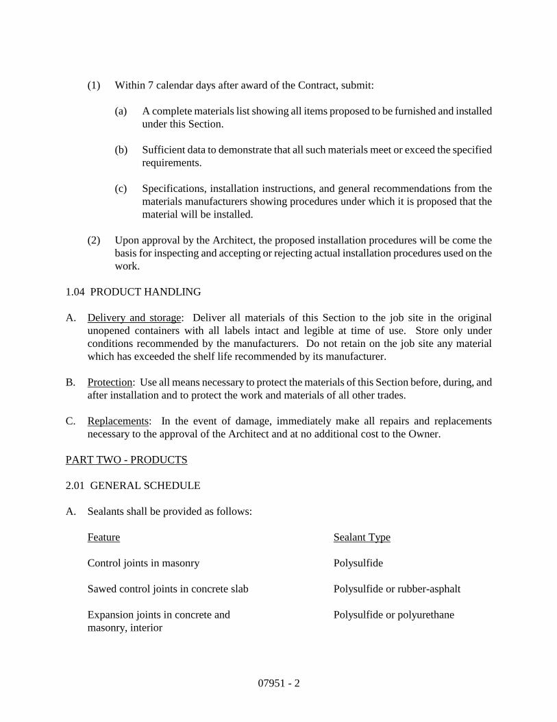
07951 - 2
(1) Within 7 calendar days after award of the Contract, submit:
(a) A complete materials list showing all items proposed to be furnished and installed
under this Section.
(b) Sufficient data to demonstrate that all such materials meet or exceed the specified
requirements.
(c) Specifications, installation instructions, and general recommendations from the
materials manufacturers showing procedures under which it is proposed that the
material will be installed.
(2) Upon approval by the Architect, the proposed installation procedures will be come the
basis for inspecting and accepting or rejecting actual installation procedures used on the
work.
1.04 PRODUCT HANDLING
A. Delivery and storage: Deliver all materials of this Section to the job site in the original
unopened containers with all labels intact and legible at time of use. Store only under
conditions recommended by the manufacturers. Do not retain on the job site any material
which has exceeded the shelf life recommended by its manufacturer.
B. Protection: Use all means necessary to protect the materials of this Section before, during, and
after installation and to protect the work and materials of all other trades.
C. Replacements: In the event of damage, immediately make all repairs and replacements
necessary to the approval of the Architect and at no additional cost to the Owner.
PART TWO - PRODUCTS
2.01 GENERAL SCHEDULE
A. Sealants shall be provided as follows:
Feature Sealant Type
Control joints in masonry Polysulfide
Sawed control joints in concrete slab Polysulfide or rubber-asphalt
Expansion joints in concrete and Polysulfide or polyurethane
masonry, interior
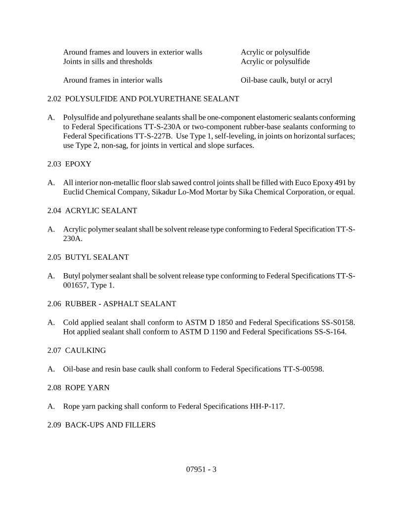
07951 - 3
Around frames and louvers in exterior walls Acrylic or polysulfide
Joints in sills and thresholds Acrylic or polysulfide
Around frames in interior walls Oil-base caulk, butyl or acryl
2.02 POLYSULFIDE AND POLYURETHANE SEALANT
A. Polysulfide and polyurethane sealants shall be one-component elastomeric sealants conforming
to Federal Specifications TT-S-230A or two-component rubber-base sealants conforming to
Federal Specifications TT-S-227B. Use Type 1, self-leveling, in joints on horizontal surfaces;
use Type 2, non-sag, for joints in vertical and slope surfaces.
2.03 EPOXY
A. All interior non-metallic floor slab sawed control joints shall be filled with Euco Epoxy 491 by
Euclid Chemical Company, Sikadur Lo-Mod Mortar by Sika Chemical Corporation, or equal.
2.04 ACRYLIC SEALANT
A. Acrylic polymer sealant shall be solvent release type conforming to Federal Specification TT-S-
230A.
2.05 BUTYL SEALANT
A. Butyl polymer sealant shall be solvent release type conforming to Federal Specifications TT-S-
001657, Type 1.
2.06 RUBBER - ASPHALT SEALANT
A. Cold applied sealant shall conform to ASTM D 1850 and Federal Specifications SS-S0158.
Hot applied sealant shall conform to ASTM D 1190 and Federal Specifications SS-S-164.
2.07 CAULKING
A. Oil-base and resin base caulk shall conform to Federal Specifications TT-S-00598.
2.08 ROPE YARN
A. Rope yarn packing shall conform to Federal Specifications HH-P-117.
2.09 BACK-UPS AND FILLERS
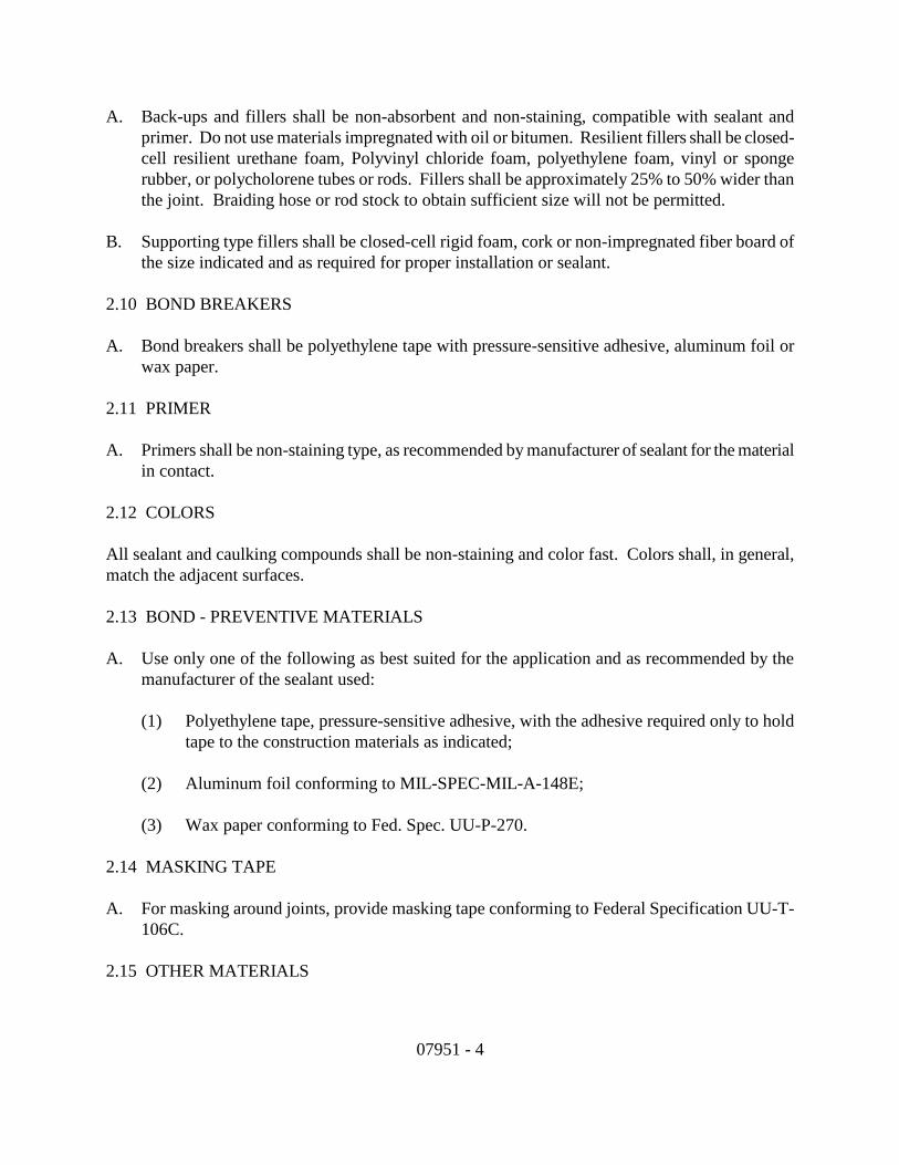
07951 - 4
A. Back-ups and fillers shall be non-absorbent and non-staining, compatible with sealant and
primer. Do not use materials impregnated with oil or bitumen. Resilient fillers shall be closed-
cell resilient urethane foam, Polyvinyl chloride foam, polyethylene foam, vinyl or sponge
rubber, or polycholorene tubes or rods. Fillers shall be approximately 25% to 50% wider than
the joint. Braiding hose or rod stock to obtain sufficient size will not be permitted.
B. Supporting type fillers shall be closed-cell rigid foam, cork or non-impregnated fiber board of
the size indicated and as required for proper installation or sealant.
2.10 BOND BREAKERS
A. Bond breakers shall be polyethylene tape with pressure-sensitive adhesive, aluminum foil or
wax paper.
2.11 PRIMER
A. Primers shall be non-staining type, as recommended by manufacturer of sealant for the material
in contact.
2.12 COLORS
All sealant and caulking compounds shall be non-staining and color fast. Colors shall, in general,
match the adjacent surfaces.
2.13 BOND - PREVENTIVE MATERIALS
A. Use only one of the following as best suited for the application and as recommended by the
manufacturer of the sealant used:
(1) Polyethylene tape, pressure-sensitive adhesive, with the adhesive required only to hold
tape to the construction materials as indicated;
(2) Aluminum foil conforming to MIL-SPEC-MIL-A-148E;
(3) Wax paper conforming to Fed. Spec. UU-P-270.
2.14 MASKING TAPE
A. For masking around joints, provide masking tape conforming to Federal Specification UU-T-
106C.
2.15 OTHER MATERIALS
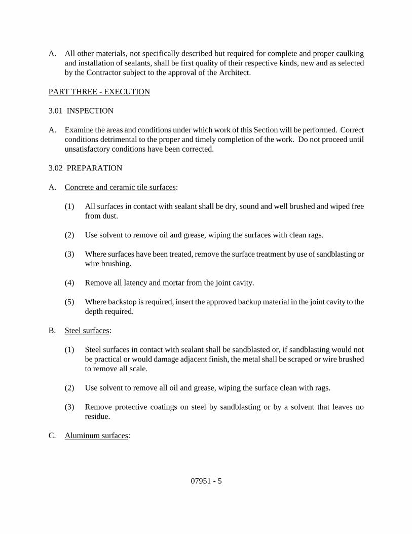
07951 - 5
A. All other materials, not specifically described but required for complete and proper caulking
and installation of sealants, shall be first quality of their respective kinds, new and as selected
by the Contractor subject to the approval of the Architect.
PART THREE - EXECUTION
3.01 INSPECTION
A. Examine the areas and conditions under which work of this Section will be performed. Correct
conditions detrimental to the proper and timely completion of the work. Do not proceed until
unsatisfactory conditions have been corrected.
3.02 PREPARATION
A. Concrete and ceramic tile surfaces:
(1) All surfaces in contact with sealant shall be dry, sound and well brushed and wiped free
from dust.
(2) Use solvent to remove oil and grease, wiping the surfaces with clean rags.
(3) Where surfaces have been treated, remove the surface treatment by use of sandblasting or
wire brushing.
(4) Remove all latency and mortar from the joint cavity.
(5) Where backstop is required, insert the approved backup material in the joint cavity to the
depth required.
B. Steel surfaces:
(1) Steel surfaces in contact with sealant shall be sandblasted or, if sandblasting would not
be practical or would damage adjacent finish, the metal shall be scraped or wire brushed
to remove all scale.
(2) Use solvent to remove all oil and grease, wiping the surface clean with rags.
(3) Remove protective coatings on steel by sandblasting or by a solvent that leaves no
residue.
C. Aluminum surfaces:

07951 - 6
(1) Aluminum surfaces in contact with sealant shall be cleaned of temporary protective
coatings, dirt, oil and grease.
(2) When masking tape is used for a protective cover, remove the tape just prior to applying
the sealant.
(3) Use only such solvents to remove protective coatings as are recommended for that
purpose by the manufacturer of the aluminum work, and which are non-staining.
3.03 INSTALLATION OF BACKUP MATERIALS
A. Use only the backup material recommended by the manufacturer of the sealant and approved by
the Architect for the particular installation, compressing the backup material 25% to 50% to
secure a positive and secure fit. When using backup for tube or rod stock, avoid lengthwise
stretching of the material. Do not twist or braid hose or rod backup stock.
3.04 PRIMING
A. Use only the primer recommended by the manufacturer of the sealant and approved by the
Architect for the particular installation. Apply the primer in strict accordance with the
manufacturer's recommendations as approved by the Architect.
3.05 BOND-BREAKER INSTALLATION
A. Install an approved bond-breaker where recommended by the manufacturer of the sealant and
where directed by the Architect, adhering strictly to the installation recommendations as
approved by the Architect.
3.06 INSTALLATION OF SEALANTS
A. General: Prior to start of installation in each joint, verify the joint type according to the details
in the Drawings, and verify that the required proportion of width of joint has been secured.
B. Equipment: Apply sealant under pressure with hand or power-actuated gun or other appropriate
means. Guns shall have nozzle or proper size and shall provide sufficient pressure to
completely fill joints as designed.
C. Masking: Thoroughly and completely mask all joints where the appearance of sealant on
adjacent surfaces would be objectionable.
D. Installation of sealant: Install the sealant in strict accordance with the manufacturer's
recommendations as approved by the Architect, thoroughly filling all joints to the
recommended depth.
07951 - 7
E. Tooling: Tool all joints to the profile shown on the details in the Drawings.
F. Clean up:
(1) Remove masking tape immediately after joints have been tooled.
(2) Clean adjacent surfaces free from sealant as the installation progresses. Use solvent or
cleaning agent as recommended by the sealant manufacturer.
END OF SECTION

08210 - 1
Section 08210
WOOD DOORS
PART ONE - GENERAL
1.01 DESCRIPTION
A. Work included: Furnish and deliver to the job site all wood doors indicated on the Drawings,
specified herein, or needed for a complete and proper installation.
B. Related work described elsewhere:
(1) Carpentry Work - Section 06001
(2) Finish Hardware - Section 8710
1.02 QUALITY ASSURANCE
A. Standards: Comply with standards specified herein and with the General Requirements.
B. Qualifications of manufacturer: All wood doors shall meet the NWMA approval and I.S. 1
series requirements. Fire doors shall also bear the UL label for the designated rating.
1.03 SUBMITTALS
A. General: Comply with the provisions of the general requirements.
B. Product data: After award of Contract, submit:
(1) Complete materials list showing all items proposed to be furnished and delivered under
this Section.
(2) Sufficient data to demonstrate that all such items meet or exceed the specified
requirements.
(3) A copy of the guarantee proposed to be furnished.
1.04 GUARANTEE
A. Upon delivery of the doors of this Section to the job site, and as condition of their acceptance,
deliver to the Owner two copies of an agreement written on the door manufacturer's standard
form, signed by the door manufacturer and the Contractor agreeing to replace or repair defective
doors which have warped (bow, cup, or twist). The guarantee shall also include refinishing and
08210 - 2
reinstalling which may be required due to repair or replacement of defective doors. Guarantee
shall be in effect for a period of one year following date of acceptance.
1.05 PRODUCT HANDLING
A. Protection: Protect the materials of this Section during transit, storage, and handling to prevent
deterioration, damage and soiling.
B. Replacements: In the event of damage, immediately make all repairs and replacements
necessary to the approval of the Architect and at no additional cost to the Owner.
PART TWO - PRODUCTS
2.01 WOOD DOORS
A. General: Interior doors shall be of the sizes, types, and designs shown on the Drawings. Doors
shall be oak, pre-finished, with no dark spots or extreme variations.
B. Adhesives and bonds: Use only adhesives and bonds conforming to NWMA I.S. - 1 standards,
Type II, for interior wood doors. Adhesives shall be non-staining.
C. Warp tolerances shall be in accordance with NWMA I.S. - 1.
D. Hardware: Doors shall be pre-machined for hardware.
PART THREE - EXECUTION
3.01 DELIVERY
A. Deliver the work of this Section to the job site in a timely manner to permit the orderly progress
of the total work.
3.02 INSTALLATION
A. Installation of the work of this Section is described in Carpentry Section 06001.
END OF SECTION
08221-1
SECTION 08221
FIBERGLASS REINFORCED DOOR AND FRAME SYSTEM
PART 1 GENERAL
1.1 SECTION INCLUDES
A. Fiberglass Reinforced Plastic (FRP) Doors.
B. Fiberglass Door Frames.
C. Fiberglass Louvers.
D. Fiberglass Reinforced Plastic (FRP) Transoms.
1.2 RELATED SECTIONS
A. Section 07900 - Joint Sealers: Perimeter sealant and backup materials.
B. Section 08710 - Door Hardware.
C. Section 08800 - Glazing.
1.3 REFERENCES
A. ASTM D 523 - Standard Test Method for Specular Gloss.
B. ASTM D 635 - Standard Test Method for Rate of Burning and/or Extent and
Time of Burning of Self-Supporting Plastics in a Horizontal Position.
C. ASTM E 84 - Standard Test Method for Surface Burning Characteristics of
Building Materials.
D. ASTM E 152 - Standard Methods of Fire Tests of Door Assemblies.
E. NFPA 252 - Standard Methods of Fire Tests of Door Assemblies.
F. SDI 100 - Recommended Specifications for Steel Doors and Frames.
G. UL 10B - Standard for Fire Tests of Door Assemblies.
H. UL 305 - Standard for Panic Hardware.
1.4 PERFORMANCE REQUIREMENTS
A. Door opening assemblies:
1. Maximum flame spread 25 in accordance with ASTM E 84, self-
extinguishing in accordance with ASTM D 635.
2. USDA accepted.
B. Fire rated assemblies: Comply with requirements of UL10B, NFPA 252, and

08221-2
ASTM E 152; UL ______ rating, with doors and frames bearing rating labels.
C. Fire rated assemblies: Comply with requirements of UL10B, NFPA 252, and
ASTM E 152; UL ratings indicated on drawings, with doors and frames
bearing rating labels.
1.5 SUBMITTALS
A. Submit under provisions of Section 01300.
B. Manufacturer's data sheets on each product to be used, including:
1. Preparation instructions and recommendations.
2. Storage and handling requirements and recommendations.
3. Installation methods.
C. Shop Drawings:
1. Plans: Indicate location of each door opening assembly in project.
2. Elevations: Dimensioned elevation of each type door opening
assembly in project; indicate sizes and locations of door hardware, and
lites and louvers, if specified.
3. Details: Installation details of each type installation condition in
project; indicate installation details of glazing, if specified.
4. Schedule: Indicate each door opening assembly in project; cross-
reference to plans, elevations, and details.
D. Selection Samples: For each finish product specified, two complete sets of
color chips representing manufacturer's full range of available colors and
patterns.
E. Verification Samples: For each finish product specified, two samples,
minimum size 6 inches (150 mm) square, representing actual product, color,
and patterns.
F. Test Reports: Certified test reports showing compliance with specified
performance characteristics and physical properties.
G. Closeout: Submit warranty documents specified herein.
1.6 QUALITY ASSURANCE
A. Manufacturer Qualifications: Company specializing in manufacturing
fiberglass doors and frames with a minimum documented experience of ten
years.
B. Installer Qualifications: Company specializing in installation of fiberglass
doors and frames with minimum three years documented experience.

08221-3
1.7 DELIVERY, STORAGE, AND HANDLING
A. Deliver materials in manufacturer's unopened, undamaged packaging, with
manufacturer's labels intact.
B. Inspect and report damage to doors at time of delivery.
C. Store products in manufacturer's unopened packaging until ready for
installation.
D. Store door assemblies in on end, to prevent damage to face corners and
edges.
1.8 WARRANTY
A. Manufacturer's Warranty: Manufacturer's 15-year warranty against failure
due to corrosion from specified environment.
PART 2 PRODUCTS
2.1 MANUFACTURERS
A. Acceptable Manufacturer: Fib-R-Dor, Div. of Advance Fiberglass, Inc.,
which is located at: 7516 Counts Massie Rd. ; N. Little Rock, AR 72113;
Toll Free Tel: 800-FIB-RDOR; Tel: 501-758-9494; Fax: 501-758-9496;
Email: [email protected]; Web: www.fibrdor.com
B. Substitutions: Permitted.
C. Requests for substitutions will be considered in accordance with provisions
of Section 01600.
D. Provide all fiberglass doors and frames from a single manufacturer.
2.2 MATERIALS
A. Fiberglass Mat: Glass fiber chopped strand, minimum 1.5 ounces per square
foot.
B. Resins: Manufacturer's formulation for fabricating units to meet specified
requirements.
C. Anchors: Manufacturer's standard stainless steel expansion anchors for
existing openings, and stainless steel masonry tee anchors for new
construction.
D. Fasteners: Stainless steel.
E. Glazing: Type specified in Section 08800; factory installed.

08221-4
2.3 COMPONENTS
A. Non-rated Fiberglass Reinforced Plastic (FRP) Doors:
1. Thickness: 1-3/4 inches (45 mm).
2. Thermal Insulating Value: 'R' factor 11.
3. Construction:
a. Core: End-grain balsa wood, resin-impregnated.
b. Door Plates: Molded in one continuous piece, resin reinforced
with hand-laid glass fiber mat, nominal 1/8 inch (3 mm) thick,
minimum 15 mil gel-coated surface.
c. Door Edges: Minimum 3 layers resin-reinforced glass fiber mat,
nominal 3/8 inch (9.5 mm) thick, machine tooled.
4. Sizes: Indicated on drawings.
5. Finish: Smooth gloss surface, minimum value of 88 in accordance with
ÅSTM D 523.
a. Color: White finish.
b. Color: Gray finish.
c. Color: Tan finish.
d. Color: Dark Brown finish.
e. Color: _____________.
B. Fire-rated Fiberglass Reinforced Plastic (FRP) Doors:
1. Thickness: 1-3/4 inches (45 mm).
2. Thermal Insulating Value: 'R' factor 11.
3. Construction:
a. Core: Fire-resistant mineral core.
b. Door Plates: Molded in one continuous piece, resin reinforced
with hand-laid glass fiber mat, nominal 1/8 inch (3 mm) thick,
minimum 25 mil gel-coated surface.
c. Door Edges: Minimum two layers resin-reinforced glass fiber
mat, nominal 1/4 inch (6 mm) thick, machine tooled.
4. Sizes: Indicated on drawings.
5. Finish: Smooth gloss surface, minimum value 88 in accordance with
ÅSTM D 523.
a. Color: White finish.
b. Color: Gray finish.
c. Color: Tan finish.
d. Color: Dark Brown finish.
e. Color: _____________.
C. Non-rated Fiberglass Frames:
1. Construction: One-piece pultruded fiberglass reinforced plastic,
minimum 1/4 inch wall thickness, jamb-to-head joints mitered and
reinforced with FRP clips and stainless steel fasteners; conforming to
SDI requirements for performance equivalent to 16 gage steel frames.
2. Frame profile: 5-3/4 inches (146 mm) deep, 2 inches (51 mm) wide
face; double rabbeted with 5/8 inch (16 mm) high stop.
08221-5
3. Sizes: Indicated on drawings.
4. Finish: Satin Co-Extruded finish, with true and consistent color
throughout frame thickness.
a. Color: White CO-X Finish.
b. Color: Gray CO-X Finish.
c. Color: Tan CO-X Finish.
d. Color: Dark Brown CO-X Finish.
e. Color: _____________.
D. Fire-rated Frames: UL approved, and as follows:
1. Construction: Type 304 stainless steel.
2. Construction: Galvaneal steel, primer finish.
3. Sizes: For door sizes and frame profiles indicated on drawings.
E. Frame Anchors: Types recommended by manufacturer for project
conditions.
F. Louvers in Non-rated Doors:
1. Construction: Molded solid vanes; pultruded fiberglass reinforced
plastic construction.
2. Sizes: Indicated on drawings.
3. Finish: Satin pigmented finish, with true and consistent color
throughout frame thickness.
a. Color: White finish.
b. Color: Gray finish.
c. Color: Tan finish.
d. Custom Gelcoated Color: Color as selected by the Architect.
G. Louvers in Fire-rated Doors: UL approved for indicated fire resistance
rating.
H. Lites in Non-rated Doors:
1. Stops: Pultruded fiberglass reinforced plastic construction.
2. Glazing: Specified in Section 08800.
3. Sizes: Indicated on drawings.
4. Fasteners: Stainless steel screws.
I. Lites in Fire-rated Doors: UL approved, and as follows:
1. Frames: Type 304 stainless steel.
2. Frames: Cold-rolled steel, gelcoated to match door color.
3. Frames: Cold-rolled steel, bronze powder coat finish.
4. Glazing: Specified in Section 08800.
5. Sizes: Indicated on drawings.
6. Fasteners: Stainless steel screws.
J. Fiberglass Reinforced Plastic (FRP) Transoms: Match adjacent door
construction and color.
K. Door Hardware: Specified Section 08710.

08221-6
L. Door Hardware: Supplied by door manufacturer, UL-listed for fire-rated
openings, and as follows:
1. Hinges: Location and quantity indicated on approved shop drawings,
and as follows:
a. Type: Full-mortise, ball-bearing stainless steel butts, 4-1/2
inches by 4-1/2 inches (114 mm by 114 mm) template; stainless
steel fasteners.
b. Acceptable product: Fib-R-Dor BB51.
2. Closers:
a. Type: Standard service.
b. Acceptable product: International 984.
3. Closers:
a. Type: Severe service.
b. Acceptable product: LCN 4041-EDA-SRI-ALXTB.
4. Closers:
a. Type: Stainless steel arms.
b. Acceptable product: Norton 1601SS.
5. Kick Plates: 18 gage stainless steel, with beveled edges and brushed
finish; stainless steel fasteners.
6. Locksets and Latchsets: Ball knob, exposed surfaces of stainless steel,
Grade 2.
7. Locksets and Latchsets: Ball knob, exposed surfaces of stainless steel,
Grade 1.
8. Push/Pulls: Stainless steel, with beveled edges and brushed finish, size
3-1/2 inches (89 mm) by 15 inches (381 mm); stainless steel fasteners.
9. Exit Devices:
a. Type: Conforming to UL 305; equipped with pull handle and
thumb latch.
b. Acceptable product: RIM 19-R Series.
2.4 FABRlCATlON
A. Fiberglass Reinforced Plastic (FRP) Doors:
1. Minimum glass fiber to resin ratio: 30 percent.
2. Mortise for lockset, and recess for strike plate in lock stile.
3. Embed steel reinforcement for hinges in fiberglass matrix; provide for
hinge leaf recesses in hinge stile.
B. Fiberglass Frames:
1. Mortise for lock strike, and recess for strike plate in lock jamb.
2. Reinforce for hinges and other indicated hardware.
PART 3 EXECUTION
3.1 EXAMINATION
A. Verify openings are ready to receive work and opening dimensions and
clearances are as indicated on approved shop drawings. Do not begin
08221-7
installation until openings have been properly prepared.
B. If opening preparation is the responsibility of another installer, notify
Architect of unsatisfactory preparation before proceeding.
3.2 PREPARATION
A. Acclimate doors and frames to site conditions for a minimum of 24 hours
before installation.
B. Do not remove labels from fire-rated doors and frames.
3.3 INSTALLATION
A. Install door opening assemblies in accordance with approved shop drawings,
SDI 100, and manufacturer's printed installation instructions, using
installation methods and materials specified in installation instructions.
B. Use anchorage devices to securely fasten sliding door assembly to wall
construction without distortion or imposed stresses.
C. Coordinate installation of thermal insulation at shim spaces at frame
perimeter.
D. Installation of door hardware is specified in Section 08710.
E. Install door hardware in accordance with manufacturer's printed instructions,
using through-bolts to secure surface applied hardware.
F. Site Tolerances: Maintain plumb and level tolerances specified in
manufacturer's printed installation instructions.
3.4 ADJUSTING
A. Adjust doors in accordance with door manufacturer's maintenance
instructions to swing open and shut without binding, and to remain in place at
any angle without being moved by gravitational influence.
B. Adjust door hardware to operate correctly in accordance with hardware
manufacturer's maintenance instructions.
3.5 CLEANING
A. Clean surfaces of door opening assemblies and sight-exposed door hardware
in accordance with manufacturer's maintenance instructions.
B. Remove labels and visible markings.
3.6 PROTECTION
A. Protect installed products until completion of project.
08221-8
B. Touch-up, repair or replace damaged products before Substantial
Completion.
3.7 SCHEDULE
A. Schedules: Refer to Door Schedule indicated on drawings.
END OF SECTION

08522 - 1
SECTION 08522
VINYL CLAD WINDOWS
PART ONE - GENERAL
1.01 DESCRIPTION
A. Work included: Furnish and deliver to the site all vinyl clad windows shown on the
Drawings, specified herein, and installed as recommended by the manufacturer as
approved by the Architect.
B. Related work described elsewhere:
(1) Carpentry Section 06001
(2) Sealants and Caulking Section 07951
(3) Finish Hardware Section 08710
1.02 QUALITY ASSURANCE
A. Standards: Comply with standards specified herein and with the General Requirements.
B. Qualifications of Manufacturer: Products used in the work of this Section shall be
produced by the manufacturers regularly engaged with manufacture of similar items and
with a history of successful production acceptable to the Architect.
1.03 SUBMITTALS
A. General: Comply with the provisions of the General Requirements, applicable laws,
safety and building codes.
B. Product date: Within 30 calendar days of the award of Contract, submit:
(1) Complete materials list showing all items proposed to be furnished and delivered
under this Section.
(2) Sufficient data to demonstrate that all such items meet or exceed the specified
requirements.
(3) A copy of the guarantee proposed to be furnished.
1.04 PRODUCT HANDLING

08522 - 2
A. Protection: Protect materials of this Section during transit, storage, handling and
installation to prevent deterioration, damage and soiling.
(1) Package and mark each window for location to correspond with opening number on
the Drawings.
B. Replacements: In the event of damage, immediately make all repairs and replacements
necessary to the approval of the Architect and at no additional cost to the Owner.
PART TWO - PRODUCTS
2.01 VINYL CLAD WINDOWS
A. Exterior windows: Marvin or equal.
PART THREE - EXECUTION
3.01 DELIVERY
A. Deliver all vinyl clad window units to the job site in a timely manner to permit orderly
progress of the total work.
3.02 INSTALLATION
A. Installation of window units shall be as shown on the Drawings, specified herein and in
strict accordance with the manufacturer's installation direction as approved by the
Architect.
END OF SECTION
08710 - 1
Section 08710
FINISH HARDWARE
PART ONE - GENERAL
1.01 DESCRIPTION
A. Work included: Furnish, install and\or deliver to the job site all finish hardware to match
existing hardware required to complete the work as indicated on the Drawings and specified
herein. Provide all trim attachments, and fastenings specified or required for proper and
complete installation.
B. Related work described elsewhere:
(1) Carpentry Work – Section 06001
(2) Metal Doors – Section 08110
(3) Aluminum & Glass Doors – Section 08120
(4) Wood Doors – Section 08210
1.02 QUALITY ASSURANCE
A. Standards: Comply with standards specified in this Section and with the General
Requirements.
B. Qualifications of manufacturers: Products used in the work of this Section shall be
produced by manufacturers regularly engaged in manufacture of similar items and with a
history of successful production acceptable to the Owner.
1.03 SUBMITTALS
A. General: Comply with the general conditions.
B. Product data:
(1) Within 7 calendar days after award of the Contract, submit:
(a) Complete materials list of all items proposed to be furnished and delivered
under this Section.
08710 - 2
(aa) Identify each hardware item by manufacturer, the manufacturer's catalog
number, and the location of the item in the work.
(bb) Make the list in form suitable for ready checking by the Architect.
(b) Manufacturer's specifications, catalog cuts, and other data required to
demonstrate compliance with specified requirements.
(2) Approval of the hardware list by the Architect shall not relieve the Contractor from
the responsibility for furnishing all required finish hardware.
C. Templates: In a timely manner to ensure orderly progress of the work deliver templates or
physical samples of the approved finish hardware items to pertinent manufacturers of
interfacing items, such as door and frames.
1.04 PRODUCT HANDLING
A. Packing and Marking: Individually package each unit of finish hardware, complete with
proper fastenings and appurtenances, clearly marked on the outside to indicate the contents
and specific location in the work.
B. Protection: Use all means necessary to protect materials of this Section before, during and
after delivery to the job site and to protect the work and materials of all other trades.
C. Replacements: In the event of damage, immediately make all repairs and replacements
necessary to the approval of the Owner and at no additional cost to the Owner.
PART TWO - PRODUCTS
2.01 GENERAL
A. Proprietary Products: References to specific proprietary products are used to establish
minimum standards of utility and quality. Unless otherwise approved by the Owner,
provide only the specific products. Design is based on the materials specified. Other
materials may be considered by the Owner in accordance with the provisions of the general
requirements.
B. Manufacturers: The manufacturer shall be as shown on Hardware Schedule on the drawings
or equal as approved by the architect.
C. Fasteners: Furnish all finish hardware with all necessary screws, bolts, and other fasteners
of suitable size and type to anchor the hardware in position for long life under hard use.
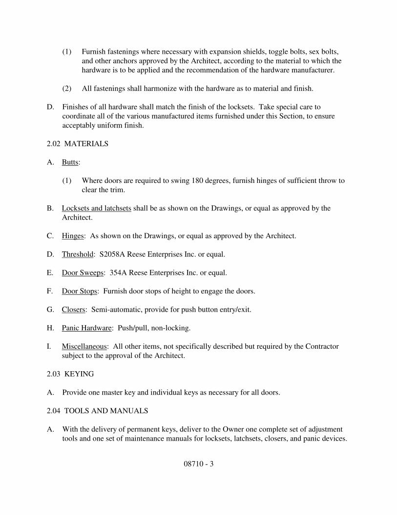
08710 - 3
(1) Furnish fastenings where necessary with expansion shields, toggle bolts, sex bolts,
and other anchors approved by the Architect, according to the material to which the
hardware is to be applied and the recommendation of the hardware manufacturer.
(2) All fastenings shall harmonize with the hardware as to material and finish.
D. Finishes of all hardware shall match the finish of the locksets. Take special care to
coordinate all of the various manufactured items furnished under this Section, to ensure
acceptably uniform finish.
2.02 MATERIALS
A. Butts:
(1) Where doors are required to swing 180 degrees, furnish hinges of sufficient throw to
clear the trim.
B. Locksets and latchsets shall be as shown on the Drawings, or equal as approved by the
Architect.
C. Hinges: As shown on the Drawings, or equal as approved by the Architect.
D. Threshold: S2058A Reese Enterprises Inc. or equal.
E. Door Sweeps: 354A Reese Enterprises Inc. or equal.
F. Door Stops: Furnish door stops of height to engage the doors.
G. Closers: Semi-automatic, provide for push button entry/exit.
H. Panic Hardware: Push/pull, non-locking.
I. Miscellaneous: All other items, not specifically described but required by the Contractor
subject to the approval of the Architect.
2.03 KEYING
A. Provide one master key and individual keys as necessary for all doors.
2.04 TOOLS AND MANUALS
A. With the delivery of permanent keys, deliver to the Owner one complete set of adjustment
tools and one set of maintenance manuals for locksets, latchsets, closers, and panic devices.

08710 - 4
PART THREE - EXECUTION
3.01 DELIVERIES
A. Stockpile all items sufficiently in advance to ensure their availability and make all necessary
deliveries in a timely manner to ensure orderly progress of the total work.
3.02 INSPECTION AND INSTALLATION
A. Upon completion of the installation, and as a condition of its acceptance, visually inspect all
finish hardware furnished under this Section and place in optimum working condition.
3.03 KEY CHANGING
A. At the time of final acceptance of the work, void the construction key system and in the
presence of the Architect, demonstrate that the specified keying system is operating
properly.
END OF SECTION
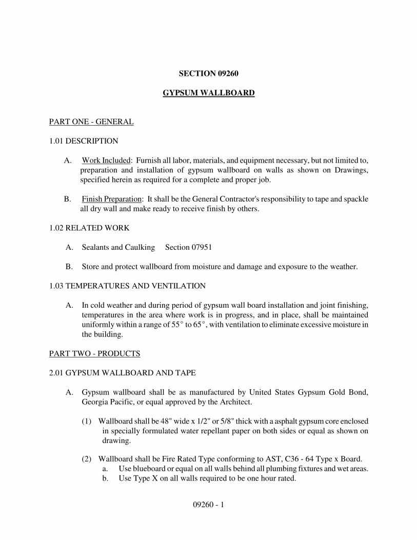
09260 - 1
SECTION 09260
GYPSUM WALLBOARD
PART ONE - GENERAL
1.01 DESCRIPTION
A. Work Included: Furnish all labor, materials, and equipment necessary, but not limited to,
preparation and installation of gypsum wallboard on walls as shown on Drawings,
specified herein as required for a complete and proper job.
B. Finish Preparation: It shall be the General Contractor's responsibility to tape and spackle
all dry wall and make ready to receive finish by others.
1.02 RELATED WORK
A. Sealants and Caulking Section 07951
B. Store and protect wallboard from moisture and damage and exposure to the weather.
1.03 TEMPERATURES AND VENTILATION
A. In cold weather and during period of gypsum wall board installation and joint finishing,
temperatures in the area where work is in progress, and in place, shall be maintained
uniformly within a range of 55E to 65E, with ventilation to eliminate excessive moisture in
the building.
PART TWO - PRODUCTS
2.01 GYPSUM WALLBOARD AND TAPE
A. Gypsum wallboard shall be as manufactured by United States Gypsum Gold Bond,
Georgia Pacific, or equal approved by the Architect.
(1) Wallboard shall be 48" wide x 1/2" or 5/8" thick with a asphalt gypsum core enclosed
in specially formulated water repellant paper on both sides or equal as shown on
drawing.
(2) Wallboard shall be Fire Rated Type conforming to AST, C36 - 64 Type x Board.
a. Use blueboard or equal on all walls behind all plumbing fixtures and wet areas.
b. Use Type X on all walls required to be one hour rated.
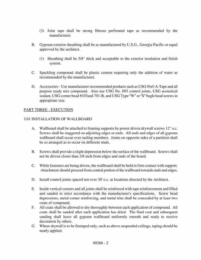
09260 - 2
(3) Joint tape shall be strong fibrous perforated tape as recommended by the
manufacturer.
B. Gypsum exterior sheathing shall be as manufactured by U.S.G., Georgia Pacific or equal
approved by the architect.
(1) Sheathing shall be 5/8" thick and acceptable to the exterior insulation and finish
system.
C. Spackling compound shall be plastic cement requiring only the addition of water as
recommended by the manufacturer.
D. Accessories - Use manufacturer recommended products such as USG-Perf-A-Tape and all
purpose ready mix compound. Also use USG No. 093 control joints, USG acoustical
sealant, USG corner bead #103and 701-B, and USG Type AW@ or AS@ bugle head screws in
appropriate size.
PART THREE - EXECUTION
3.01 INSTALLATION OF WALLBOARD
A. Wallboard shall be attached to framing supports by power driven drywall screws 12" o.c.
Screws shall be staggered on adjoining edges or ends. All ends and edges of all gypsum
wallboard shall occur over nailing members. Joints on opposite sides of a partition shall
be so arranged as to occur on different studs.
B. Screws shall provide a slight depression below the surface of the wallboard. Screws shall
not be driven closer than 3/8 inch from edges and ends of the board.
C. While fasteners are being driven, the wallboard shall be held in firm contact with support.
Attachment should proceed from central portion of the wallboard towards ends and edges.
D. Install control joints spaced not over 30' o.c. at locations directed by the Architect.
E. Inside vertical corners and all joints shall be reinforced with tape reinforcement and filled
and sanded in strict accordance with the manufacturer's specifications. Screw head
depressions, metal corner reinforcing, and metal trim shall be concealed by at least two
coats of compound.
F. All coats shall be allowed to dry thoroughly between each application of compound. All
coats shall be sanded after each application has dried. The final coat and subsequent
sanding shall leave all gypsum wallboard uniformly smooth and ready to receive
decoration by others.
G. Where drywall is to be firetaped only, such as above suspended ceilings, taping should be
neatly applied.

09260 - 3
3.02 INSTALLATION OF SHEATHING
A. Sheathing shall be installed as required for installation of exterior insulation and finish
system as shown on drawings.
3.03 PROTECTION
A. Proper protection shall be provided during the work for floors, windows, doors and other
designated areas.
B. Defective work shall be corrected to the satisfaction of the Architect and at no expense of
the Owner.
END OF SECTION

09660 - 1
Section 09660
RESILIENT FLOORING
PART ONE - GENERAL
1.01 DESCRIPTION
A. Work included: Provide all resilient flooring, complete in place, as indicated on the
Drawings, specified herein, or otherwise needed for a complete and proper installation of
the work of this Section.
1.02 QUALITY ASSURANCE
A. Use adequate numbers of skilled workmen who are thoroughly trained and experienced in
the necessary crafts and who are completely familiar with the specified requirements and the
methods needed for proper performance of the work of this Section.
1.03 SUBMITTALS
A. General: Comply with the general requirements of these Specifications. Submit the
following product data for approval after award of the contract.
(1) Manufacturer's specifications and other data to demonstrate compliance with these
specifications.
(2) Samples of the full range of colors and patterns and of exposed accessories from
proposed manufacturers.
(3) Manufacturer's recommended installation procedures, material list and shop drawing
indicating seam locations and structure.
B. The manufacturer's recommended installation procedures when accepted will be the basis
for inspection and acceptance or rejection of work.
1.04 PRODUCT HANDLING
A. Delivery and storage: Deliver materials to the job site and store in their original unopened
containers with all labels intact and legible at time of use. Store materials in strict
accordance with the manufacturer's recommendations.
B. Protection: Use all means necessary to protect materials of this Section before, during, and
after installation and to protect installed work and materials of all other trades.

09660 - 2
C. Replacements: In the event of damage, immediately make all repairs and replacements
necessary to the approval of the Architect and at no additional cost to the Owner.
PART TWO - PRODUCTS
2.01 MATERIALS, GENERAL
A. Vinyl Tile as specified on Architectural Drawings.
(1) Mohawk Group – LVT (Luxury Vinyl Tile)
Style: Select Step Stone #C0007 Color: Tea Tin T003M
Size: 18” X 36”, 20 mil, Glue Down
Representative: Jennifer Hodgson (317) 258-5168
(2) Armstrong – VCT (Vinyl Composition Tile)
Style: Standard Excelon Color: Animal Crackers
Size: 12” X 12”, 3.2 mil, Glue Down
Representative: Kathleen Bultman (317) 412-2945
B. Adhesives shall be waterproof and stabilized type as recommended by the manufacturer of
the approved resilient material. Asphalt emulsions and other non-waterproof types will not
be acceptable.
2.02 OTHER MATERIALS
A. All other materials, not specifically described but required for a complete and proper
installation of the work in this Section, shall be as recommended by the manufacturer of the
resilient materials used, and as approved by the Architect.
PART THREE - EXECUTION
3.01 INSPECTION
A. General: Examine the areas and conditions under which resilient flooring is to be placed.
Correct conditions detrimental to the proper and timely completion of the work. Do not
proceed until unsatisfactory conditions have been corrected.
B. Surface shall be smooth, level, at the required finish elevation, without more than 3 mm
(1/8") in 3 m (10'-0") variation from level or slopes shown.

09660 - 3
3.02 PREPARATION
A. Subfloors: Prior to start of the laying tile units, broom clean or vacuum all surfaces to be
covered and inspect the subfloors. Start of laying tile will indicate acceptance of subfloor
conditions.
3.03 INSTALLATION
A. General:
(1) Install tile only after all finishing operations, including painting, have been completed.
Moisture content of concrete slabs, building air temperature and relative humidity
must be within limits recommended by tile manufacturer.
(2) Place tile units with adhesive cement in strict compliance with the manufacturer's
recommendation. Butt tile units tightly to vertical surfaces, thresholds, nosing and
edging. Scribe as necessary around obstructions and to produce neat joints, laid tight,
even and in straight, parallel lines.
(3) Extend tile units into toe spaces, door reveals, and in closets and similar openings.
(4) Maintain reference markers, holes, or openings that are in place or plainly marked for
future cutting by repeating on the finish tile as marked in the subfloor. Use chalk or
other non-permanent marking device.
(5) Lay tile from center markers, holes, or openings that are in place or plainly marked for
future cutting by repeating on the finish tile as marked in the subfloor. Use chalk or
other non-permanent marking device.
(6) Lay tile from center marks established with principal walls, discounting minor off-
sets, so that tile at opposite edges of the room are of equal width. Adjust as necessary
to avoid use of cut width less than 7.5 cm (3") at room perimeters. Lay tile square to
room axis.
B. Matching:
(1) Match tiles for color and pattern by using tile from cartons in the same sequence as
manufactured and packaged. Cut tile neatly to and around all fixtures. Broken,
cracked, chipped or deformed tile are not acceptable.
(2) Tightly cement tile to sub-base without open cracks, voids, raising and puckering at
joints, telegraphing of adhesive spreader marks through tile, or other surface
imperfections.

09660 - 4
(3) Lay tile in running bond pattern with grain in all tile running in the same direction,
perpendicular to the pattern.
3.04 CLEANING AND PROTECTION
A. Remove excess adhesive or other surface blemishes from the tile, using neutral type cleaners
recommended by the tile manufacturer. Protect installed flooring from damage until
acceptance by the Architect.
3.05 FINISHING
A. After completion of the work and just prior to final inspection, thoroughly clean tile floors
and accessories. Apply wax and buff, with the type of wax, number of coats, and buffing
procedures recommended by the tile manufacturer.
END OF SECTION
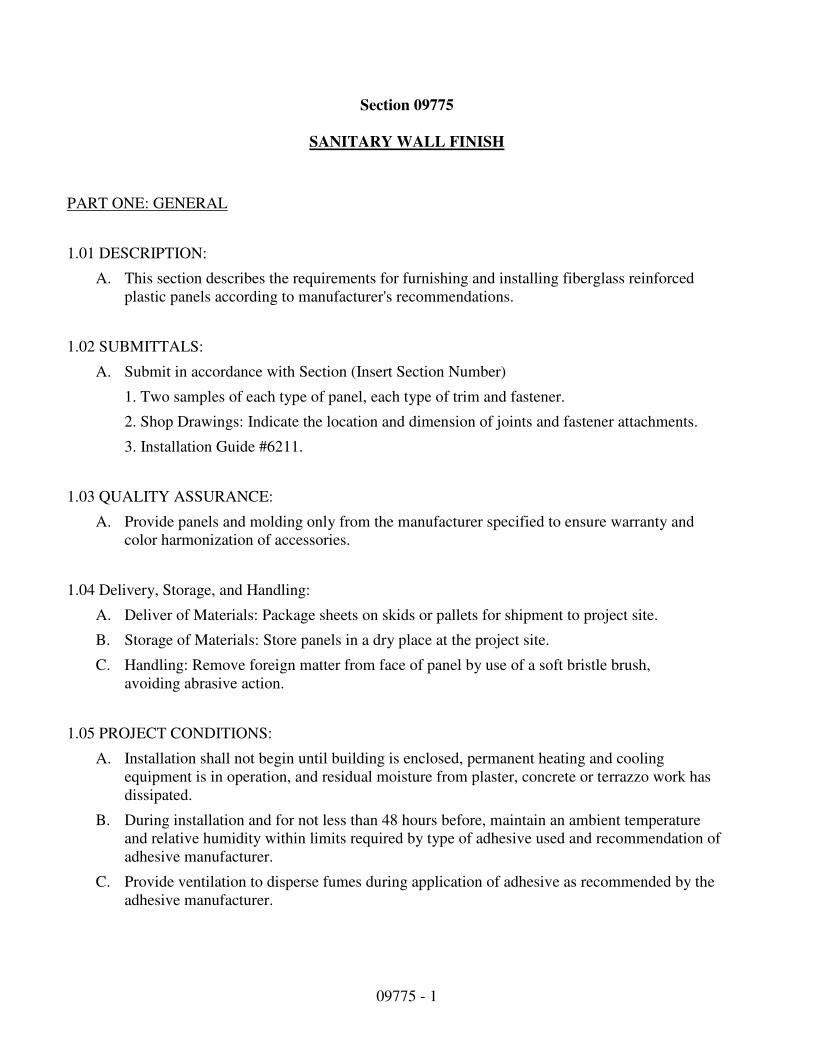
09775 - 1
Section 09775
SANITARY WALL FINISH
PART ONE: GENERAL
1.01 DESCRIPTION:
A. This section describes the requirements for furnishing and installing fiberglass reinforced
plastic panels according to manufacturer's recommendations.
1.02 SUBMITTALS:
A. Submit in accordance with Section (Insert Section Number)
1. Two samples of each type of panel, each type of trim and fastener.
2. Shop Drawings: Indicate the location and dimension of joints and fastener attachments.
3. Installation Guide #6211.
1.03 QUALITY ASSURANCE:
A. Provide panels and molding only from the manufacturer specified to ensure warranty and
color harmonization of accessories.
1.04 Delivery, Storage, and Handling:
A. Deliver of Materials: Package sheets on skids or pallets for shipment to project site.
B. Storage of Materials: Store panels in a dry place at the project site.
C. Handling: Remove foreign matter from face of panel by use of a soft bristle brush,
avoiding abrasive action.
1.05 PROJECT CONDITIONS:
A. Installation shall not begin until building is enclosed, permanent heating and cooling
equipment is in operation, and residual moisture from plaster, concrete or terrazzo work has
dissipated.
B. During installation and for not less than 48 hours before, maintain an ambient temperature
and relative humidity within limits required by type of adhesive used and recommendation of
adhesive manufacturer.
C. Provide ventilation to disperse fumes during application of adhesive as recommended by the
adhesive manufacturer.

09775 - 2
PART TWO: PRODUCTS
2.01 MATERIALS:
A. Wall and/or ceiling panels shall be KEMLITE Kemply with Surfaseal fiberglass reinforced
plastic panels as manufactured by KEMLITE COMPANY, Joliet, Illinois, USA Phone: 1-800-
435-0080 or 1-815-467-8600, Fax: 1-815-467-8666
1. Wall Panels:
Wall Panels shall be: (choose one substrate from "Kemply Wall Panels" table) substrate
with a factory laminated white (choose one skin from "Kemply Wall Panels" table) skin,
size to be (choose size and skin one or two sides from "Kemply Wall Panels" table).
2. Wall panels are specified on Architectural Drawings.
B. ALL PANELS MEET USDA/FSIS REQUIREMENTS.
The Kemply panels above, except for the 3/32" OSB with 0.05" Glasbord-PWI skin one side,
have not been tested for physical properties or for fire resistance. The Glasbord finish has
been tested (see Kemlite Technical Bulletins 65024, 6229 and 6283). Substrate physical
properties and fire resistance are the responsibility of the substrate manufacturer. Kemlite
makes no claims as to the products worthiness of the composite for any specific application,
overall physical properties, or fire resistance.
Numerical flame spread and smoke development ratings are not intended to reflect hazards
presented by Kemlite Company products or any other material under actual fire conditions.
These ratings are determined by small scale tests conducted by independent testing
facilities using the American Society for Testing and Materials E-84 test standard
(commonly referred to as the "Tunnel Test"). KEMLITE PROVIDES THESE RATINGS FOR
MATERIAL COMPARISON PURPOSES ONLY. Like other organic building materials (e.g.
wood), panels made of fiberglass reinforced plastic resins will burn. When ignited, frp may
produce dense smoke very rapidly. All smoke is toxic. Fire safety requires proper design of
facilities and fire suppression systems, as well as precautions during construction and
occupancy. Local codes, insurance requirements and any special needs of the user of the
product will determine the correct fire-rated interior finish and fire suppression system
necessary for a specific installation.
1. Division Bars, Corner Trim: Panel manufacturer's standard length extruded vinyl pieces;
longest length possible to eliminate end joints.
2. Fasteners: Non-corrosive drive rivets.
PART THREE-PREPARATION
3.01 PREPARATION
A. Examine backup surfaces to determine that corners are plumb and straight, surfaces are
smooth, uniform, clean, and free from foreign matter, nails countersunk, joints and cracks
filled flush and smooth with the adjoining surface.

09775 - 3
B. Do not begin installation until backup surfaces are put into satisfactory condition.
3.02 APPLICATION
A. Do all cutting with carbide tipped saw blades or drill bits, or cut with snips.
B. Install panels with manufacturer's recommended gap for panel field and corner joints.
C. Fastener holes in the panels must be predrilled 1/8" (3.2mm) oversize.
D. For trowel type and application of adhesive, follow adhesive manufacturer's
recommendation.
E. Using products acceptable to manufacturer, install the frp panel system in accordance with
panel manufacturer's printed instructions, Installation Guide #6211.
3.03 CLEANING
A. Remove any adhesive or excessive sealant from panel face using solvent or cleaner
recommended by panel manufacturer.
B. For current distribution and technical information, please call or write: Kemlite Company,
Inc., P.O. Box 2429, Joliet, IL 60434, (800) 435-0080, (815) 467-8600, FAX (815) 467-
8666. Kemlite, Glasbord, Surfaseal, Thread on the backside and Fluorescent Thread on the
Frontside are registered trademarks of Kemlite Company, Inc.
END OF SECTION
09900 - 1
Section 09900
PAINTING
PART ONE - GENERAL
1.01 DESCRIPTION
A. Work included: Paint and finish all exposed surfaces in accordance with the types of finish
shown on the Finish Schedule, in the Drawings and as specified herein.
B. Related work described elsewhere: Priming or priming and finishing of certain surfaces are
specified to be factory performed under pertinent other Sections.
C. Work not included:
(1) Do not include painting which is specified under other Sections.
(2) Unless otherwise indicated, painting is not required on surfaces in concealed areas and
inaccessible areas such as furred spaces, foundation spaces, utility tunnels, pipe spaces,
and duct shafts.
(3) Metal surfaces of anodized aluminum, stainless steel, chromium plate, copper, bronze,
and similar finished materials will not require painting under this Section except as may
be specified herein.
(4) Do not paint any moving parts of operating units; mechanical or electrical parts such as
valve operators, linkages, sinkages, sensing devices, and motor shafts, unless otherwise
indicated.
(5) Do not paint over any required labels or equipment identification, performance rating,
name or nomenclature plates.
D. Shop priming: Shop priming of ferrous metal items is included under the various sections
for structural steel, miscellaneous metal, hollow metal work, and similar items. Also for
fabricated components such as architectural woodwork, wood casework, and shop-fabricated
or factory-built mechanical and electrical equipment or accessories.
E. Definitions: The term "paint" as used herein, means all coating systems materials including
primers, emulsions, epoxy, enamels, sealers, fillers, and other applied materials whether used
as prime, intermediate, or finish coats.
1.02 QUALITY ASSURANCE
09900 - 2
A. In case the paint manufacturer's specifications or instructions differ from the above
specifications, apply the more stringent requirements to this work. Color finishes on metal
surfaces shall be warranted for a period of: 15 years against chipping, cracking, blistering
and peeling and for 10 years against excessive chalking and fading. The finishes shall also
meet ASTM D-659-44 No. 8 rating when applied to vertical walls, or in excess of ASTM D-
659-44 No. 6 rating when applied to roof surfaces and against fading in excess of 5.0 NBS
units.
B. Qualifications of manufacturer: Products used in the work of this Section shall be produced
by manufacturers regularly engaged in manufacture of similar items and with a history of
successful production acceptable to the Architect.
C. Qualifications of workmen:
(1) Provide at least one person who shall be present at all times during execution of the work
of this Section, who shall be thoroughly familiar with the specified requirements and the
materials and methods needed for their execution, and who shall direct all work
performed under this Section.
(2) Provide adequate numbers of workmen skilled in the necessary crafts and properly
informed of the methods and materials to be used.
(3) In acceptance or rejection of the work of this Section, the Architect will make no
allowance for lack of skill on the part of workmen.
D. Paint coordination:
(1) Provide finish coats which are compatible with the prime coats used.
(2) Review other Sections of these Specifications as required, verifying the prime coats to be
used and assuring compatibility of the total coating system for the various substrata.
(3) Upon request, furnish information on the characteristics of the specific finish materials to
ensure that compatible prime coats are used.
(4) Provide barrier coats over non-compatible primers, or remove the primer and re-prime as
required.
(5) Notify the Owner in writing of anticipated problems in using the specified systems
over prime coating supplied under other sections.
1.03 SUBMITTALS
A. General: Comply with provisions of the General Requirements of these Specifications.

09900 - 3
B. Manufacturers' data: Within 7 calendar days after award of the Contract, submit:
(1) Complete materials list of all items proposed to be furnished and installed under this
Section.
(2) Manufacturer's specifications and other data required to demonstrate compliance with the
specified requirements.
(3) For information only, submit two copies of manufacturer's specifications including paint
analysis and application instructions for each material. Indicate in the transmittal that a
copy of each manufacturer's instructions has been distributed to the applicator.
C. Upon receipt of review comments, make all revisions and corrections, and resubmit if so
required.
1.04 PRODUCT HANDLING
A. Delivery of materials: Deliver all materials to the job site in original, new and unopened
containers bearing the manufacturer's name and label showing the following information:
(1) Name or title of the material;
(2) Fed. Spec. number, if applicable;
(3) Manufacturer's stock number;
(4) Manufacturer's name;
(5) Contents by volume for major constituents;
(6) Thinning instructions;
(7) Application instructions.
B. Storage of materials: Provide proper storage to prevent damage to, and deterioration of, paint
materials.
C. Protection: Use all means necessary to protect the materials of this Section before, during
and after installation and to protect the work and materials of all other trades.
D. Replacements: In the event of damage; immediately make all repairs and replacements
necessary to the approval of the Architect and at no additional cost to the Owner.
09900 - 4
1.05 JOB CONDITIONS
A. Surface temperatures: Do no apply solvent-thinned paint when the temperature of surfaces to
be painted and the surrounding air temperature are below 45oF., unless otherwise permitted
by the manufacturer's printed instructions as approved by the Architect.
B. Weather conditions: Do not apply paint in snow, rain, fog, or mist, or when the relative
humidity exceeds 85% or to damp or wet surfaces; unless otherwise permitted by the
manufacturer's printed instructions as approved by the Architect. Applications may be
continued during inclement weather within the temperature limits specified by the paint
manufacturer during application and drying periods.
1.06 EXTRA STOCK
A. Amount: Upon completion of the work of this Section, deliver to the Owner an extra stock
equaling 10% of each color, type, and gloss of paint used on the work.
B. Packaging: Tightly seal each container and clearly label with the contents and location used.
PART TWO - PRODUCTS
2.01 PAINT MATERIALS
A. Paint products and materials shall be manufactured by Sherwin Williams, Pittsburgh Paint,
MAB, and Porter Paints or equal products of other manufacturers must be approved by the
Architect.
B. General: Provide the best quality grade of the various types of coatings as regularly
manufactured by paint materials manufacturers approved by the Architect. Materials not
displaying the manufacturer's identification as a standard best-grade product will not be
acceptable.
C. Durability: Provide paints of durable and washable quality. Do not use paint materials
which will not withstand normal washing as required to remove pencil marks, ink, ordinary
soil, and similar material showing discoloration, loss of gloss, staining, or other damage.
D. Colors and glosses: The Architect will select colors to be used in the various types of paint
specified and will be the sole judge of acceptability of the various glosses obtained from the
materials proposed to be used in the work.
E. Undercoats and thinners: Provide undercoat paint produced by the same manufacturer as the
finish coat. Use only the thinners recommended by the paint manufacturer, and use only the
09900 - 5
recommended limits. Insofar as practicable, use undercoat, finish coat, and thinner material
as parts of a unified system of paint finish.
F. Standards: Provide paint materials which meet or exceed the standards listed for each
application in the Painting Schedule in Part Three of this Section.
2.02 APPLICATION EQUIPMENT
A. General: For application of the approved paint, use only such equipment as is recommended
for application of the particular paint by the manufacturer of the particular paint, and as
approved by the Architect.
B. Compatibility: Prior to actual use of application equipment, use all means necessary to verify
that the proposed equipment is actually compatible with the material to be applied and that
the integrity of the finish will not be jeopardized by use of the proposed application
equipment.
C. Other materials: All other materials, not specifically described but required for a complete
and proper installation of the work of this Section, shall be new, first-quality of their
respective kinds, and as selected by the Contractor subject to the approval of the Architect.
PART THREE - EXECUTION
3.01 SURFACE CONDITIONS
A. Inspection: Prior to installation of the work of this Section, carefully inspect the installed
work of all other trades and verify that all such work is complete to the point where this
installation may properly commence. Verify that painting may be completed in strict
accordance with the original design and with the manufacturer's recommendations as
approved by the Architect.
B. Discrepancies: Do not proceed in areas of discrepancy until all such discrepancies have been
fully resolved.
3.02 MATERIALS PREPARATION
A. Mix and prepare painting materials in strict accordance with the manufacturer's
recommendations as approved by the Owner.
B. Store materials not in actual use in tightly covered containers.
C. Maintain containers used in storage, mixing, and application of paint in a clean condition,
free from foreign materials and residue.
09900 - 6
D. Stirring: Stir all materials before application to produce a mixture of uniform density, and as
required during the application of materials. Do not stir into the material any film which may
form on the surface. Remove this film and, if necessary, strain the material before using.
3.03 SURFACE PREPARATION
A. General:
(1) Perform all preparation and cleaning procedures in strict accordance with the paint
manufacturer's recommendations as approved by the Architect.
(2) Removal all removable items which are in place and are not scheduled to receive paint
finish, or provide surface-applied protection prior to surface preparation and painting
operations.
(3) Following completion of painting in each space or area, reinstall the removed items by
using workmen skilled in the necessary trades.
(4) Clean each surface to be painted prior to applying paint or surface treatment.
(5) Removal all oil and grease with clean cloths and cleaning solvents of low toxicity and a
flash point in excess of 30oC. (100 degrees F.), prior to start of mechanical cleaning.
(6) Schedule the cleaning and painting so that dust and other contaminants from the cleaning
process will not fall into wet, newly painted surfaces.
B. Preparation of wood surfaces:
(1) Clean all surfaces until they are completely free from dirt, oil, and grease.
(2) Smooth all finished wood surfaces exposed to view, using the proper sandpaper. Where
so required, use varying degrees of coarseness in sandpaper to produce a uniformly
smooth and unmarred wood surface.
(3) Unless specifically approved by the Owner, do not proceed with painting of wood
surfaces until the moisture content of the wood is 12% or less as measured by a moisture-
meter approved by the Architect.
C. Preparation of metal surfaces:
(1) Thoroughly clean all surfaces until they are completely free form dirt, oil and grease.

09900 - 7
(2) On galvanized surfaces, use solvent for the initial cleaning and then treat the surface
thoroughly with phosphoric acid etch. Removal all etching solution before proceeding.
(3) Allow to dry thoroughly before application of paint.
D. Preparation of concrete surfaces:
(1) Remove all curing compounds and efflorescence from concrete and masonry surfaces and
roughen as required to provide good adhesion of paints. If washing of the surface of
masonry is required, us trisodium phosphate solution followed by clean water rinse. Fill
all minor holes and grind off projection to produce a uniform surface.
3.04 PAINT APPLICATION
A. General:
(1) Slightly vary the color of succeeding coats. Do not apply additional coats until the
complete coat has been inspected and approved by the Architect. Only the inspection and
approved coats of paint will be considered in determining the number of coats applied.
(2) Sand and dust between enamel coats to remove all defects visible to the unaided eye from
a distance of five feet.
B. Drying:
(1) Allow sufficient drying time between coats. Modify the period as recommended by the
material manufacturer to suit adverse weather conditions.
(2) Oil-base and oleo-resinous solvent-type paints shall be considered dry for recoating when
the paint feels firm, does not deform or feel sticky under moderate pressure of
the thumb, and the application of another coat of paint does not cause lifting or loss of
adhesion of the undercoat.
C. Brush application: Brush out and work all brush coats onto the surface in an even film.
Cloudiness, spotting, holidays, laps, brush marks, runs, sags, ropiness, and other surface
imperfections will not be acceptable.
D. Spray application:
(1) Confine spray application to metal framework and similar surfaces where hand brush
work would be inferior.
09900 - 8
(2) Wherever spray application is used, apply each coat to provide the equivalent hiding of
brush applied coats. Do not double back with spray equipment for the purpose of
building up film thickness of two coats in one pass.
E. Completed work shall match the approved color charts and manufacturer's specifications for
color, texture, and coverage. Remove, refinish, or repaint all work not in compliance with
specified requirements.
3.05 PAINTING SCHEDULE
A. General:
(1) Colors shall be standard colors provided by the specified manufacturers and as shown on
the Drawings or as directed by the Architect.
(2) Local and National V.O.C. (Volatile Organic Compound) regulations are constantly
changing; consult with manufacturer representatives before finalizing the selection.
END OF SECTION

10670 - 1
SECTION 10670
STORAGE SHELVING
PART 1 GENERAL
1.1 SECTION INCLUDES
A. Vinyl-coated ventilated shelving.
B. Adjustable shelf systems.
C. Storage accessories.
1.2 RELATED SECTIONS
A. Section 06001 - Carpentry
B. Section 09260 - Gypsum Wallboard
1.3 SUBMITTALS
A. Submit under provisions of Section 01300.
B. Product Data: Manufacturer's catalog data, detail sheets, and specifications.
C. Shop Drawings: Prepared specifically for this project; show dimensions of shelving
and interface with other products.
D. Selection Samples: For each finish product specified, two complete sets of color
chips representing manufacturer's full range of available colors and patterns.
E. Verification Samples: For each finish product specified, two samples, minimum size
6 inches (150 mm) square representing actual product, color, and patterns.
1.4 QUALITY ASSURANCE
A. Manufacturer Qualifications: All primary products specified in this section will be
supplied by a single manufacturer with a minimum of ten years experience.
B. Installer Qualifications: All products listed in this section are to be installed by a
single installer with a minimum of five years demonstrated experience in installing
products of the same type and scope as specified.
C. Mock-Up: Provide a mock-up for evaluation of surface preparation techniques and
application workmanship.
1. Finish areas designated by Architect.
2. Do not proceed with remaining work until workmanship, color, and sheen are
approved by Architect.
3. Refinish mock-up area as required to produce acceptable work.

10670 - 2
1.5 DELIVERY, STORAGE, AND HANDLING
A. Store products in manufacturer's unopened packaging until ready for installation.
1.6 PROJECT CONDITIONS
A. Maintain environmental conditions (temperature, humidity, and ventilation) within
limits recommended by manufacturer for optimum results. Do not install products
under environmental conditions outside manufacturer's absolute limits.
1.7 WARRANTY
A. At project closeout, provide to Owner or Owner's Representative an executed copy
of the manufacturer's standard limited warranty against manufacturing defect,
outlining its terms, conditions, and exclusions from coverage.
PART 2 PRODUCTS
2.1 MANUFACTURERS
A. Acceptable Manufacturer: Closetmaid Corp., 650 S.W. 27th Ave. ; Ocala, FL 34471;
Toll Free Tel: 800-221-0641 Web: www.closetmaid.com or equal.
B. Requests for substitutions will be considered in accordance with provisions of
Section 01600.
C. Provide all storage shelving from a single manufacturer.
2.2 MATERIALS
A. Steel Wire: Basic cold drawn, Grade C-1006; average tensile strength over 100,000
psi (690 MPa); coated.
B. Wire Coating: Proprietary heavy-duty polyvinyl chloride (PVC) formula resin,
plasticizers, stabilizers, pigments and other additives.
1. Thickness: 7 to 17 mil (0.178 to 0.432 mm).
2. Classification: No ingredients listed as hazardous per OSHA
29CFR1910.0017.
2.3 MANUFACTURED UNITS
A. Coated Wire Shelving:
1. SuperSlide/Linen: 1 inch (25 mm) spacing.
a. Color: White Wire.
b. Color: Satin Chrome.
c. Closet Rod Support: Part # 925.
d. 3/4 inch (19 mm) Closet Rod: Part # 2012.
e. Internal Closet Rod Cap: Part # 2081.
f. Pre-Loaded Side Wall Bracket: Part # 979.
g. Corner Closet Rod: Part # 5649/5748.
2. Close Mesh: 5/8 inch (16 mm) spacing.

10670 - 3
a. Color: White Wire.
b. Color: Satin Chrome.
3. TotalSlide: 5/8 inch (16 mm) spacing.
a. Color: White Wire.
4. Shelf & Rod: 1 inch (25 mm) spacing.
a. Color: White Wire.
5. Linen: 1 inch (25 mm) spacing.
a. Color: Satin Chrome.
B. Accessories: As required and as manufactured by ClosetMaid Corp.
1. Wall Clips.
2. End Brackets.
3. Support Brackets.
4. Poles.
5. Standards.
6. Shelf Brackets.
7. Pole Clips.
8. Hang Track.
PART 3 EXECUTION
3.1 EXAMINATION
A. Verification of Conditions:
1. Prepared spaces are sized and located in accordance with shop drawings.
2. Framing, reinforcement, and anchoring devices are correct type and are located
in accordance with shop drawings.
B. Installer's Examination:
1. Examine conditions under which installation is to be performed; submit written
notification if such conditions are unacceptable.
2. Installation activities started before unacceptable conditions have been
corrected is prohibited.
3. Installation indicates installer's acceptance of conditions.
3.2 INSTALLATION
A. Cut shelves 1/2 inch to 1-3/8 inches (12.7 to 35 mm) shorter than actual wall
measurements; cap all exposed ends.
B. Install shelving plumb and level at heights indicated in accordance with shop
drawings and manufacturer's printed installation instructions.
C. Place wall clips No. 910, 911 every 10 to 12 inches (254 to 305 mm) on level line.
D. Install end brackets No. 932, 933, 914, 940, and 941 on same level line as wall clips,
centered on the front rods of shelves. Support shelves 36 inches (914 mm) maximum
with end brackets, support brackets, or poles.

10670 - 4
E. Drill holes where required using sharp bit; do not punch.
F. Drywall: Drill 1/4 inch (6 mm) hole, insert No. 910 or 911 wall clip. Use No. 658 # 8
x 1 inch (25 mm) pin to expand anchor if unloaded.
G. Wood: Drill 1/4 inch (6 mm) hole into wood, secure wall clip with No. 8 x 1 inch (25
mm) screw or secure pole clip No. 978 directly to wood with No. 8 x 1-1/4 inch (31
mm) screws.
H. Concrete: Drill 1/4 inch (6 mm) hole with masonry bit, insert wall clip No. 911 or
978, secure with No. 8 x 1 inch (25 mm) screws.
I. Standards and Brackets:
1. Install standards vertically every 16 inches (406 mm) on studs.
2. Install horizontal tracks level, secured with screws or mollies in studs or
drywall; use hanging adapters to connect wall standards for hanging.
J. Attach shelf brackets with SuperSlide, Heavy Duty, Linen, Shelf and Rod and Close
Mesh for 12-inch (305 mm) Z-lip shelving and for 16 or 20 inches (406 or 508 mm)
decking.
K. Use lightning pole clip No. 978 for linen shelving, clip No. 977 for shelf and rod
shelving.
L. Shelf Supports:
1. Place shelf support brackets No. 1164, 1166 or 1180 vertically to the shelf,
attach with No. 954 or 955 wall anchors.
2. Install down clips No. 978, 981 or cable clips No. 612 with 1/4 inch (6 mm)
anchor on the back rod behind every support bracket.
3. 36 inches (914 mm) o.c. maximum.
4. 24 inches (610 mm) o.c. maximum.
M. Attach No. 977 or 978 pole clips at same elevations as wall clips for a given shelf;
use with No. 117, 118, 2117 or 2118 poles.
N. Use No. 120 corner support brackets on all corner "butt" joints.
O. For wall to wall installation, use lightning end bracket No. 932, 933, 940 or 941; drill
1/4 inch (6 mm) holes, and secure with No. 658 # 8 x 1 inch (25 mm) pins.
3.3 CLEANING
A. As work proceeds, maintain premises free of unnecessary accumulation of tools,
equipment, surplus materials, and debris related to this work.
B. Upon completion of installation, clean all surfaces that have become soiled during
installation.
END OF SECTION
10800 - 1
SECTION 10800
TOILET ROOM ACCESSORIES
PART ONE - GENERAL
1.01 DESCRIPTION
A. Work Included: Provide all toilet room accessories, complete, in place, as shown on the
Drawings, specified herein, and needed for a complete and proper installation.
B. Related Work Described Elsewhere:
(1) Installing, or furnishing and installing, concealed support devices for the work of this
Section, is specified in pertinent other Sections.
1.02 QUALITY ASSURANCE
A. Standards: Comply with standards specified herein and with the general requirements of these
specifications.
B. Qualifications of manufacturer: Products used in the work of this Section shall be produced by
manufacturers regularly engaged in manufacture of similar items and with a history of
successful production acceptable to the Architect.
1.03 SUBMITTALS
A. General:
(1) Comply with the general requirements of these specifications. Submit the following
product data for approval after award of the Contract.
(a) Manufacturer's specifications and other data to demonstrate compliance with
these specifications.
(b) Complete material list showing all items proposed to be furnished and installed
under the section.
(c) Manufacturer's recommended methods of installation.
(d) Complete descriptive data on fasteners proposed for each type of wall
construction, recommended mounting locations, and mounting instructions.

10800 - 2
(2) The manufacturer's recommended methods of installation, when approved by the
Architect, will become the basis for inspecting and accepting or rejecting actual
installation methods used on the work.
1.04 PRODUCT HANDLING
A. Protection: Use all means necessary to protect the materials of this Section before, during, and
after installation and to protect the work and materials of all other trades.
B. Replacements: In the event of damage, immediately make all repairs and replacements
necessary to the approval of the Architect and at no additional cost to the Owner.
PART TWO - PRODUCTS
2.01 GENERAL
A. Anchors and Fasteners: Provide anchors and fasteners capable of developing a retaining force
commensurate with the strength of the accessory to be mounted and well suited for use with the
supporting construction. Where exposed fasteners are permitted, provide oval head fasteners
with finish matching the accessory.
B. Finish: All accessory items shall be stainless with chrome finish.
C. Design is based on use of products manufactured by the Bobrick & Restoration Hardware Co.,
and catalog numbers of that manufacturer are given as an indication of the quality and style
required. Equal products by other manufacturers approved by the Owner will be accepted such
as, but not limited to, A&J, ASi, Bradley, GAMCO, McKinney/Parker, in accordance with the
General Conditions.
2.02 ACCESSORY ITEMS
A. Provide the following in the numbers and locations shown on the drawings.
PART THREE - EXECUTION
3.01 INSPECTION
A. Examine the areas and conditions under which work of this Section will be installed. Correct
conditions detrimental to proper and timely completion of the work. Do not proceed until
unsatisfactory conditions have been corrected.
10800 - 3
3.02 COORDINATION
A. Throughout construction of substrate surfaces, use all means necessary to ensure proper and
adequate provision for concealed support devices, and for finished openings, to receive the work
of this Section.
3.03 INSTALLATION
A. Install the work of this Section in strict accordance with the manufacturer's recommendations as
approved by the Architect, anchoring all components plumb, level, square, and firmly into
position for long life under hard use. Mount all items at the manufacturer's recommended
mounting height unless otherwise shown on drawings.
END OF SECTION

15400 - 1
SECTION 15400
PLUMBING
PART ONE – GENERAL
1.01 DESCRIPTION
A. Work Included: Furnish and install all plumbing fixtures, sewer, water waste and vent
piping, and all construction, materials and devices herein specified and shown on drawings
or as required to completely execute the work.
B. Related Work Described Elsewhere:
(1) Heating, Ventilating, and Air Conditioning - Section 15600
1.02 QUALITY ASSURANCE
A. Qualifications of Installers: For the actual fabrication, installation, and testing of the work
of this Section, use only thoroughly trained and experienced workmen, completely familiar
with the items required and with the manufacturer's recommended methods of installation.
In acceptance or rejection of the installed work, no allowance will be made for lack of skill
on the part of the workmen.
B. Code and Standards:
(1) Comply with all pertinent codes and regulations including the BOCA National
Plumbing Code.
C. Permits and Fees: The plumbing contractor at his expense shall furnish any necessary
permits and fees required by local ordinances and local utilities for construction and
inspection of work installed by him under this Contract. Sewer tap fees are not to be
included in the bid, but will be taken care of by the Owner.
1.03 SUBMITTALS
A. General: Comply with the general conditions of these specifications.
B. Product Data: Within 20 calendar days after the award of the Contract, submit:
(1) A complete list of all materials to be used under this Section.
(2) Manufacturer's specifications and catalog cuts as required to demonstrate compliance
with the specified requirements.
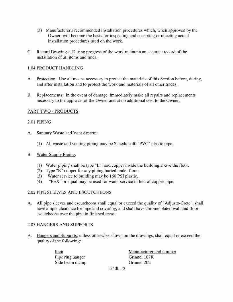
15400 - 2
(3) Manufacturer's recommended installation procedures which, when approved by the
Owner, will become the basis for inspecting and accepting or rejecting actual
installation procedures used on the work.
C. Record Drawings: During progress of the work maintain an accurate record of the
installation of all items and lines.
1.04 PRODUCT HANDLING
A. Protection: Use all means necessary to protect the materials of this Section before, during,
and after installation and to protect the work and materials of all other trades.
B. Replacements: In the event of damage, immediately make all repairs and replacements
necessary to the approval of the Owner and at no additional cost to the Owner.
PART TWO - PRODUCTS
2.01 PIPING
A. Sanitary Waste and Vent System:
(1) All waste and venting piping may be Schedule 40 "PVC" plastic pipe.
B. Water Supply Piping:
(1) Water piping shall be type "L" hard copper inside the building above the floor.
(2) Type "K" copper for any piping buried under floor.
(3) Water service to building may be 160 PSI plastic.
(4) “PEX” or equal may be used for water service in lieu of copper pipe.
2.02 PIPE SLEEVES AND ESCUTCHEONS
A. All pipe sleeves and escutcheons shall equal or exceed the quality of "Adjusto-Crete", shall
have ample clearance for pipe and covering, and shall have chrome plated wall and floor
escutcheons over the pipe in finished areas.
2.03 HANGERS AND SUPPORTS
A. Hangers and Supports, unless otherwise shown on the drawings, shall equal or exceed the
quality of the following:
Item Manufacturer and number
Pipe ring hanger Grinnel 107R
Side beam clamp Grinnel 202

15400 - 3
Trapeze hangers Superstrut A1200
Vertical riser Grinnel 261
B. Hanger rods shall conform to the following:
Pipe Size Rod Diameter
1/2 inch to 2 inch 3/8 inch
2-1/2 inch to 3-1/2 inch 1/2 inch
4 inch to 5 inch 5/8 inch
(1) At the Contractor's option, trapeze hangers may be used where parallel runs of pipe
occur. All rods on Trapeze hangers shall be 1/2 inch minimum.
2.04 ISOLATION
A. Isolate all dissimilar metals with isolators equaling or exceeding the quality of "EPCO"
dielectric unions.
2.05 INSULATION
A. Pipe insulating materials shall equal or exceed the quality of the following:
(1) Johns Manville 3/8" thick foam plastic "Aerotube" or equal.
2.06 ACCESS PLATES
A. Provide access plates equaling or exceeding the quality of Smith number 4760, prime coated
steel for painted walls, with Allen key locking devices.
2.07 FIXTURES AND EQUIPMENT
A. Provide fixtures and equipment equaling or exceeding the quality of the manufacturer and
model numbers shown on the Drawings, complete with all required stops, supplies, backing
drain, trim, and other items necessary. All fixtures shall be in color "white", unless
otherwise shown on drawings, and have stop valve and water connections. Chrome stop
valves, wastes, and supplies are to be used at all exposed areas.
2.08 OTHER MATERIALS
A. All other materials, not specifically described but required for a complete and proper
installation of the work of this Section, shall be new, first quality of their respective kinds,
and as selected by the Contractor subject to the approval of the Owner.
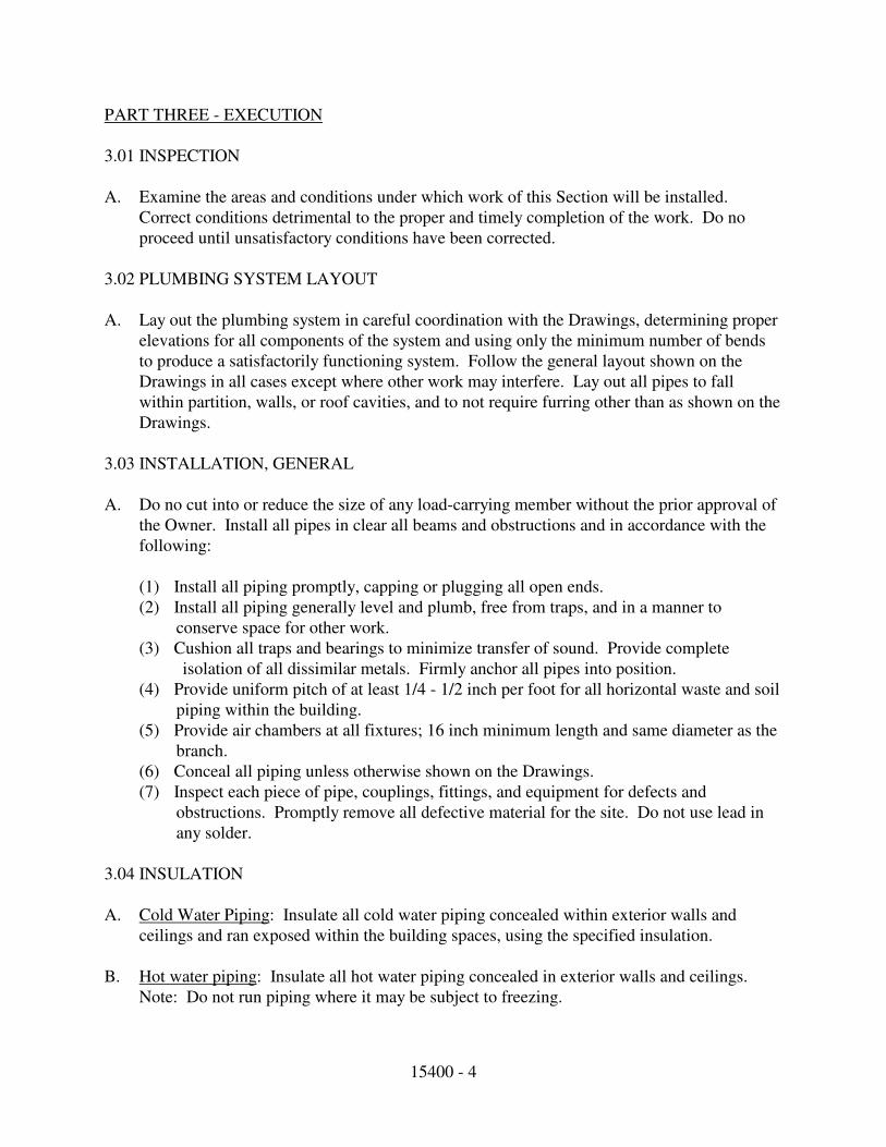
15400 - 4
PART THREE - EXECUTION
3.01 INSPECTION
A. Examine the areas and conditions under which work of this Section will be installed.
Correct conditions detrimental to the proper and timely completion of the work. Do no
proceed until unsatisfactory conditions have been corrected.
3.02 PLUMBING SYSTEM LAYOUT
A. Lay out the plumbing system in careful coordination with the Drawings, determining proper
elevations for all components of the system and using only the minimum number of bends
to produce a satisfactorily functioning system. Follow the general layout shown on the
Drawings in all cases except where other work may interfere. Lay out all pipes to fall
within partition, walls, or roof cavities, and to not require furring other than as shown on the
Drawings.
3.03 INSTALLATION, GENERAL
A. Do no cut into or reduce the size of any load-carrying member without the prior approval of
the Owner. Install all pipes in clear all beams and obstructions and in accordance with the
following:
(1) Install all piping promptly, capping or plugging all open ends.
(2) Install all piping generally level and plumb, free from traps, and in a manner to
conserve space for other work.
(3) Cushion all traps and bearings to minimize transfer of sound. Provide complete
isolation of all dissimilar metals. Firmly anchor all pipes into position.
(4) Provide uniform pitch of at least 1/4 - 1/2 inch per foot for all horizontal waste and soil
piping within the building.
(5) Provide air chambers at all fixtures; 16 inch minimum length and same diameter as the
branch.
(6) Conceal all piping unless otherwise shown on the Drawings.
(7) Inspect each piece of pipe, couplings, fittings, and equipment for defects and
obstructions. Promptly remove all defective material for the site. Do not use lead in
any solder.
3.04 INSULATION
A. Cold Water Piping: Insulate all cold water piping concealed within exterior walls and
ceilings and ran exposed within the building spaces, using the specified insulation.
B. Hot water piping: Insulate all hot water piping concealed in exterior walls and ceilings.
Note: Do not run piping where it may be subject to freezing.

15400 - 5
3.05 CLOSING IN UNINSPECTED WORK
A. Do not cover up or enclose until it has been properly and completely inspected and
approved. Should any of the work be covered up or enclosed prior to all required
inspections and approvals, uncover the work as required and, after it has been completely
inspected and approved, make all repairs and replacements with such materials and
workmanship as are necessary to the approval of the Owner, and at no additional cost to the
Owner.
3.06 TESTING
A. General: Furnish all test pumps, gages, equipment, and personnel required, and test as
necessary to demonstrate the integrity of the finished installation to the approval of all
pertinent authorities and the Owner.
B. Soil and Waste: Unless otherwise directed, plug all openings and fill with water to a height
equal to the lowest vent. Allow to stand for one hour or longer as required. Re-calk leaking
joints, as directed and then re-test.
C. Water Lines: Test and make tight at 150 psi water gauge. Retain for four hours; repair all
leaking joints as directed; and then re-test.
D. Valves: Test all bonnets for tightness. Test operate all valves at least once from closed-to-
open-to-closed positions while valve is under pressure. Test all automatic valves for proper
operation at the settings indicated. Test pressure relief valves at least three times.
E. Other: Test all piping specialties for proper operation. Test all air vent points to ensure that
air has been vented.
F. Sterilization: Sterilize all water lines after purging in accordance with the current
procedures of the American Water Works Association for flushing and disinfecting water
mains. Upon completion thoroughly flush the entire portable water system. Chlorinate only
when the building is unoccupied and deliver a copy of the certification to the Architect.
END OF SECTION

15600 - 1
SECTION 15600
HEATING, VENTILATING, AND AIR CONDITIONING
PART ONE - GENERAL
1.01 DESCRIPTION
A. Work Included: Heating, ventilating, and air conditioning required for this work is indicated on
the Drawings and includes, but is not necessarily limited to:
(1) Filters
(2) Exhaust fans
(3) Controls
(4) Ducts, dampers, grilles, registers, and diffusers
(5) Insulation of ducts
(6) All other items required for a complete and operating heating, ventilating, and air
conditioning system.
B. Related Work Described Elsewhere:
(1) Plumbing Section 15400
1.02 QUALITY ASSURANCE
A. Qualifications of Installers:
(1) For the actual fabrication, installation, and testing of work under this Section, use only
thoroughly trained and experienced workmen completely familiar with the items required
and the manufacturer's current recommended methods of installation.
(2) In acceptance or rejection of installed work, the Owner will make no allowance for lack of
skill on the part of workmen.
B. Codes and Standards: In addition to complying with all pertinent codes and regulations,
comply with all pertinent recommendations contained in "Duct Manual and Sheet Metal
Construction for Ventilating and Air Conditioning Systems", latest edition, as published by the
Sheet Metal and Air Conditioning Contractors' National Association.
1.03 SUBMITTALS
A. General: Comply with the general requirements of the specifications.
B. Product Data: Within 30 calendar days after award of the Contract submit:

15600 - 2
(1) Complete materials list of all items proposed to be furnished and the interface of ducts and
equipment with all other items.
(2) Manufacturer's recommended installation procedures which, when approved by the
Owner, will become the basis for inspecting and accepting or rejecting actual installation
procedures used on the work.
C. Record Documents: During progress of the work, maintain an accurate record of all changes
made in the heating, ventilating, and air-conditioning system from the layout and materials
shown on the approved submittals.
D. Manual: Upon completion of this portion of the work, and as a condition of its acceptance,
deliver to the Owner one copy of a Manual compiled in accordance with the provisions of
Section 0135 of these specifications. Include in each cop of the Manual a copy of the Record
Documents.
1.04 PRODUCT HANDLING
A. Protection: Use all means necessary to protect the materials of this Section before, during, and
after installation and to protect the work and materials of all other trades.
B. Replacements: In the even of damage, immediately make all repairs and replacements
necessary to the approval of the Owner and at no additional cost to the Owner.
PART TWO - PRODUCTS
2.01 EQUIPMENT
A. General: All equipment shall be the capacity and types shown on the Equipment Schedule in
the Drawings, or specifications, and shall be in the listed manufacturer and model number or
shall be an equal approved in advance by the Owner.
B. Single Source:
(1) For ease of maintenance and parts replacement, to the maximum extent possible, use
equipment of a single manufacturer.
(2) The Owner reserves the right to reject any materials list which contains equipment from
various manufacturers if suitable materials can be secured from fewer manufacturers, and
to require source of materials to be unified to the maximum extent possible.

15600 - 3
C. Ductwork: Shall be galvanized rectangular fabricated as per the latest edition of SMACNA
installation guide. HVAC ductwork branch runs may be flex duct meeting Smacna rules
connected to proper register boot fittings.
D. Insulation: Rectangular ducts shall have 1" duct liner pinned and glued. Branch runs shall be
externally wrapped with foil faced 12" insulation with seams sealed with foil tape.
E. Return air ad transfer grilles shall be "Titus", "Hart & Cooley", "Carnes", or equal.
F. Exhaust fans shall be "Broan", "Jenn Aire", "Nu-Tone" or approved equal. Restroom exhaust
fans shall be equal to Nu-tone Model QT-80 with VS-63 15 minute switch and shall be
exhausted to the building soffitt.
2.02 FIBERGLASS DUCTS
A. General: The Contractor may substitute fiberglass ducts in lieu of metal ducts, but only in
concealed areas and locations where there is no danger of physical damage to the ducts.
B. Criteria: Where fiberglass ducts are used, provide minimum nominal thickness of 1". Coat the
ends and edges of fiberglass duct sections jointed in the field, using a cementing material
which will prevent delamination and corrosion. Finish ductwork shall not impart loose fibers
or odors to the air. Ducts with largest dimension of 30" or less shall have a density of not less
than 3.25 pounds per cubic foot; ducts wider than 30" shall have a density of not less than five
pounds per cubic foot. Provide fiberglass ducts manufactured by Owens/Corning Fiberglass,
Johns-Manvill, Certainteed, Therma-Flex or approved equal.
2.03 PIPE AND FITTINGS
A. Provide pipe and fittings complying with the provisions of Section 15400 of these
Specifications.
2.04 OTHER MATERIALS
A. All other materials, not specifically described but required for a complete and proper
installation, shall be as selected by the Contractor subject to the approval of the Owner.
PART THREE - EXECUTION
3.01 SURFACE CONDITIONS
A. Inspection:
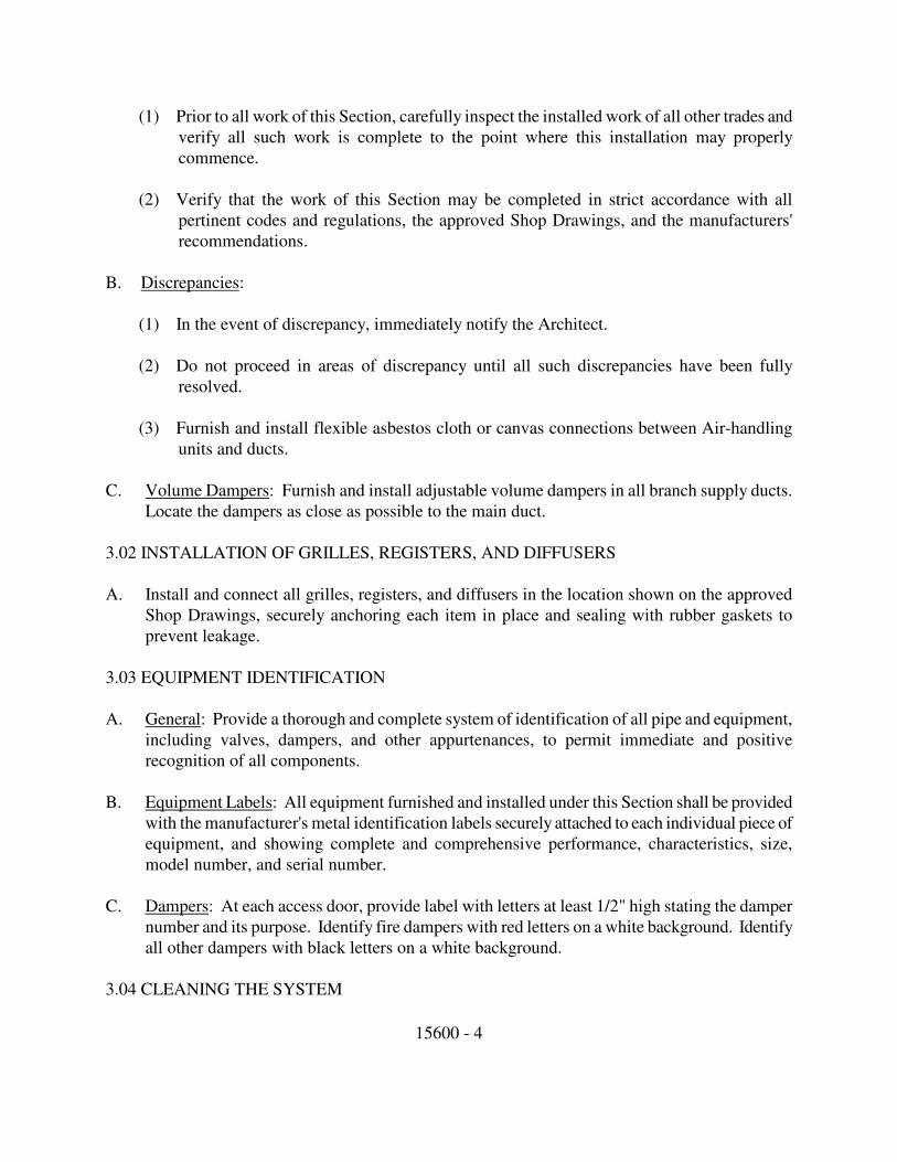
15600 - 4
(1) Prior to all work of this Section, carefully inspect the installed work of all other trades and
verify all such work is complete to the point where this installation may properly
commence.
(2) Verify that the work of this Section may be completed in strict accordance with all
pertinent codes and regulations, the approved Shop Drawings, and the manufacturers'
recommendations.
B. Discrepancies:
(1) In the event of discrepancy, immediately notify the Architect.
(2) Do not proceed in areas of discrepancy until all such discrepancies have been fully
resolved.
(3) Furnish and install flexible asbestos cloth or canvas connections between Air-handling
units and ducts.
C. Volume Dampers: Furnish and install adjustable volume dampers in all branch supply ducts.
Locate the dampers as close as possible to the main duct.
3.02 INSTALLATION OF GRILLES, REGISTERS, AND DIFFUSERS
A. Install and connect all grilles, registers, and diffusers in the location shown on the approved
Shop Drawings, securely anchoring each item in place and sealing with rubber gaskets to
prevent leakage.
3.03 EQUIPMENT IDENTIFICATION
A. General: Provide a thorough and complete system of identification of all pipe and equipment,
including valves, dampers, and other appurtenances, to permit immediate and positive
recognition of all components.
B. Equipment Labels: All equipment furnished and installed under this Section shall be provided
with the manufacturer's metal identification labels securely attached to each individual piece of
equipment, and showing complete and comprehensive performance, characteristics, size,
model number, and serial number.
C. Dampers: At each access door, provide label with letters at least 1/2" high stating the damper
number and its purpose. Identify fire dampers with red letters on a white background. Identify
all other dampers with black letters on a white background.
3.04 CLEANING THE SYSTEM

15600 - 5
A. Ductwork: After the ductwork has been tested and provide tight, thoroughly clean all
components of the ductwork and remove all dirt, scale, oil, and other foreign substances which
may have accumulated during the installation process.
B. Equipment: After the equipment has been started and proved operational, carefully clean all
accessible parts of each piece of equipment, thoroughly removing all traces of dirt, oil, grease,
and other foreign substances.
3.05 CLOSING-IN OF UNINSPECTED WORK
A. General: Do not allow or cause any of the work of this Section to be covered up or enclosed
until it has been inspected, tested, and approved, do all things necessary to uncover all such
work. After the work has been completely inspected, tested, and approved, provide all
materials and labor necessary and make all repairs necessary to restore the work to its original
and proper condition at no additional cost to the Owner.
3.06 COOPERATION WITH OTHER TRADES
A. Do all things necessary to operate with other trades in order that all systems in and work may
be installed in the best arrangement. Coordinate as required with all other trades to share space
in common areas and to provide the maximum of access to each system.
3.07 TESTING AND ADJUSTING
A. General: Provide all necessary personnel, equipment, and services and perform all tests
necessary to demonstrate the integrity of the completed installation to the approval of the
Owner and all other authorities having jurisdiction. Make all adjustments necessary to balance
the completed system in accordance with the data shown on the Drawings.
B. Ventilating and Air Conditioning System: After completion of the work of installation, test
and regulate all components of the ventilating and air-conditioning system.
3.08 INSTRUCTIONS
A. Upon completion of all required testing and balancing and at a date set by the Architect to
coincide with the Owner's acceptance of the completed work, furnish all necessary personnel
and thoroughly indoctrinate and instruct the Owner's maintenance and operation personnel in
all aspects of operation and maintenance of the installed system. Demonstrate the contents of
the Manual required to be submitted under Paragraph 1.03 above and ensure that the Owner's
personnel are thoroughly familiar with all aspects of operation and maintenance of the installed
system.
END OF SECTION
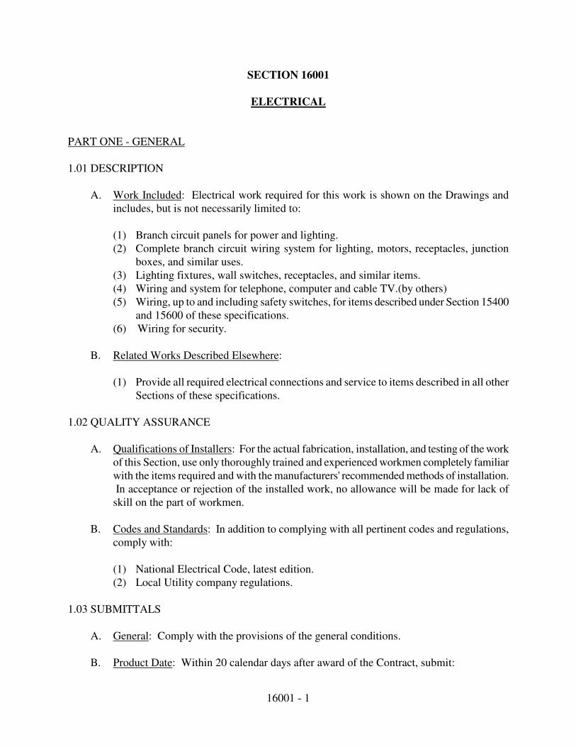
16001 - 1
SECTION 16001
ELECTRICAL
PART ONE - GENERAL
1.01 DESCRIPTION
A. Work Included: Electrical work required for this work is shown on the Drawings and
includes, but is not necessarily limited to:
(1) Branch circuit panels for power and lighting.
(2) Complete branch circuit wiring system for lighting, motors, receptacles, junction
boxes, and similar uses.
(3) Lighting fixtures, wall switches, receptacles, and similar items.
(4) Wiring and system for telephone, computer and cable TV.(by others)
(5) Wiring, up to and including safety switches, for items described under Section 15400
and 15600 of these specifications.
(6) Wiring for security.
B. Related Works Described Elsewhere:
(1) Provide all required electrical connections and service to items described in all other
Sections of these specifications.
1.02 QUALITY ASSURANCE
A. Qualifications of Installers: For the actual fabrication, installation, and testing of the work
of this Section, use only thoroughly trained and experienced workmen completely familiar
with the items required and with the manufacturers' recommended methods of installation.
In acceptance or rejection of the installed work, no allowance will be made for lack of
skill on the part of workmen.
B. Codes and Standards: In addition to complying with all pertinent codes and regulations,
comply with:
(1) National Electrical Code, latest edition.
(2) Local Utility company regulations.
1.03 SUBMITTALS
A. General: Comply with the provisions of the general conditions.
B. Product Date: Within 20 calendar days after award of the Contract, submit:

16001 - 2
(1) A complete list of all materials proposed to be furnished and installed under this
Section.
(2) Manufacturers' specifications and catalog cuts as required to demonstrate compliance
with the specified requirements.
(3) Manufacturers' recommended installation procedures which, when approved by the
Owner, will become the basis for inspecting and accepting or rejecting installation
procedures used on the work.
1.04 PRODUCT HANDLING
A. Protection: Use all means necessary to protect the materials of this Section before, during,
and after installation and to protect the work and materials of all other trades.
B. Replacements: In the event of damage, immediately make all repairs and replacements
necessary to the approval of the Owner and at no additional cost to the Owner.
PART TWO - PRODUCTS
2.01 GROUND SYSTEM
A. All equipment including switchboards, transformers, conduit system, motors, and other
apparatus, shall be grounded by conduit or conductor to cold water main or independent
grounding electrode, with ground clamps as manufactured by Burndy, T&B, or an equal
approved in advance by the Owner. Grounding shall be per the NEC.
2.02 ELECTRICAL DISTRIBUTION SYSTEM
A. Identification of Components: Identify all components by means of a neatly stenciled
label, or etched micarta labels.
B. Electric Panels: Panel shall be Square 'D' as shown on drawings.
C. Cover plates shall be standard ivory plates, or brown to match walls.
D. All switches and receptacles are to be residential grade 20 amp.
E. Mount switches 4'-6" above finish floor and wall receptacles 12" above finish floor or 12"
above cabinet counter tops.
F. Raceways and Fittings:
16001 - 3
(1) All conduit installed concealed in walls, above the ceilings, or exposed in work areas,
shall be rigid galvanized or sherardized steel conduit, or electrical metallic tubing
with compression fitting. Indenter fittings are not acceptable.
(2) Conduit installed in the floor slab or underground shall be rigid galvanized or plastic
per NEC. Conduit in direct contact with earth shall be coated with an asphaltum
paint approved, or vinyl coated schedule 80 PVC.
(3) Electrical metallic tubing (EMT) shall conform to all requirements of the National
Electrical Code.
(4) All outlets, junction boxes, and switch boxes shall be galvanized code-gage metal:
(a) Use deep boxes with conduits of 1" size or larger.
(b) Telephone outlets shall be standard 4" square boxes with single device over
and one-hole telephone plates.
(5) Pull-boxes shall be galvanized code-gage sheet metal with screwed-on covers, of size
and shape to accommodate wires without crowding and to suit the location.
(6) Provide sleeves and chases where conduits pass through floors and walls.
(7) New low voltage wiring shall be protected in all public area, and in apartments
By Wire Trak or Genova Products, vinyl wire management.
G. Conductors: Wire and cable shall be 600 V insulated NEC standard THHN or XHHW.
Branch circuit conductors within 3" of a ballast within the ballast compartment shall have
90 degree C (194 degrees F) insulation or better.
2.03 LIGHTING FIXTURES
A. General: All lighting fixtures shall be complete with all required suspension accessories,
canopies, casings, sockets, holders, reflectors, and other items, and shall be completely
wired and assembled.
B. Ballasts for all fluorescent fixtures shall be one of the high-power-factor Class P type, and
their design and construction shall conform with CBM standards and be identified as such
with the CBM-ETL label. Ballasts shall be equipped with a dual protection system
consisting of non-resetting protector in the power capacitor and a UL approved protector
adjacent to the coil.
C. Indoor lighting fixtures shall be as shown on the Fixture Schedule.
16001 - 4
2.04 OTHER MATERIALS
A. All other materials, not specifically described but required for a complete and proper
installation of the work of this Section, shall be as selected by the Contractor subject to the
approval of the Owner.
PART THREE - EXECUTION
3.01 INSPECTION
A. Examine the areas and conditions under which the work of this Section will be installed.
Correct conditions detrimental to the proper and timely completion of the work. Do not
proceed until unsatisfactory conditions have been corrected.
3.02 PREPARATION
A. Coordination:
(1) Coordinate installation of electrical items with the schedules for other work, to
prevent unnecessary delays in the total work.
(2) Where lighting fixtures and other electrical items are shown in conflict with locations
of structural members and wiring to clear the encroachment.
B. Accuracy of Data: The data indicated on the Drawings and in these specifications are as
exact as could be secured, but their absolute accuracy is not guaranteed. Exact location,
distances, levels, and other conditions will be governed by the building. Use the Drawings
and these specifications for guidance, and secure the Architect's approval of all changes in
location.
C. Measurements: Verify all measurements at the site. No extra compensation will be made
because of differences between locations shown on the Drawings and measurements at the
building.
3.03 INSTALLATION OF RACEWAY AND FITTINGS
A. Concealment: Conceal all conduit in walls or ceiling space unless otherwise specifically
approved by the Owner or indicated on the Drawings. Where conduit is allowed to be
exposed, install the conduit parallel with or at right angles to structural members, walls,
and lines of the building.
B. Installation:
(1) Keep all conduit at least 6" away from the covering on hot water pipes.

16001 - 5
(2) Keep ends of conduit closed with approved conduit seals during construction of the
building. Use conduit unions where union joints are required. Do not use running
threads.
(3) Where conduit is installed in concrete slabs, on the ground, underground, or exposed
to the weather, make all joints liquid-tight and gas-tight. Bury all underground
conduit to a depth of 2'-0" below finished grade unless otherwise shown on the
Drawings.
(4) Except for cables or wires otherwise called for, install all conductors in conduit,
metal gutter raceway, or pull boxes.
3.04 INSTALLATION OF LIGHTING FIXTURES
A. General: Install all lighting fixtures complete and ready for service, in accordance with the
Fixture Schedule on the Drawings:
(1) Wire all fixtures with fixture wiring of at least 150E C rating. Conductors in wiring
channels of fixtures mounted in rows shall be the same size as the circuit wiring
supplying the rows.
(2) Install all fluorescent fixtures straight and true with reference to adjacent walls.
(3) Install all lighting fixtures, including those mounted in continuous rows, so that the
weight of the fixture is supported either directly or indirectly by a sound and safe
structural member of the building, using adequate number and type of fasteners to
ensure a safe installation. Screwed fastenings and toggles through ceiling or wall
material are not acceptable.
B. Lamping: Provide all lamps.
3.05 INSTALLATION OF POWER EQUIPMENT
A. Provide all power and control wiring required for the work of other trades as described on
the Drawings and in the various Sections of these specifications, except where the
furnishing and installing of such wiring is specified elsewhere.
3.06 INSTALLATION OF CONDUCTORS
A. General:
(1) Unless otherwise indicated on the Drawings, all copper wires used for branch circuits
shall be number 12 TW, protected by 20 ampere circuit breakers. Install larger wires,
as indicated on the Drawings, where necessary to limit voltage drop. Do not use
aluminum.
(2) The number of wires in a conduit run may be indicated on the Drawings by cross
lines on the conduit run, where wire size is not shown, install number 12 conductors.
Provide code-size conduit for number and size of wires shown or required, unless a
16001 - 6
larger conduit size is indicated on the Drawings. Conduit is only required in
locations per the National Electric Code and as shown on Drawings.
(3) Use identified (white) neutrals and color-coded phase wires for all branch circuit
wiring. Make all splices electrically and mechanically secure with pressure-type
connectors or soldering.
(4) Insulate and tape all splices in accordance with the governing code.
B. Home Runs: The Drawings indicate the general direction of home runs. Continue all such
home runs to the panel as though the routes were completely indicated.
3.07 INSTALLATION OF PANELS
A. Installation: Unless otherwise indicated on the Drawings, install all panels with the top of
the trim 6'-3" above the finished floor. Panels located where they are not visible to the
public shall be surface mounted, if space permits.
B. Directories: Mount a typewritten directory behind glass and plastic on the inside of each
panel door. On the directory, show the circuit number and complete description of all
outlets on each circuit.
3.08 TESTING
A. General: Upon completion of this portion of the work, test all parts of the electrical
system in the presence of the Owner. Demonstrate that all equipment furnished, installed,
and/or connected under this Section of these specifications functions electrically in the
required manner.
B. Test Requirements: All systems shall test free from short circuits and grounds, shall be
free from mechanical and electrical defects, and shall show an insulation resistance
between phase conductors and ground of not less than that required by the National
Electrical Code.
C. Test all circuits for proper neutral connections.
END OF SECTION