Embed Size (px)
Citation preview

PROJECT FINAL REPORT
Grant Agreement number: 309993
Project acronym: PMJOIN
Project title: Development of a Direct Laser Joining of Hybrid Plastic-Metal components for industrial applications.
Funding Scheme: FP7-NMP-2012-SMALL-6
Period covered: from 01.02.2013 to 31.01.2016
Name of the scientific representative of the project's co-ordinator1, Title and Organisation:
Ms Carmen Sanz, Fundación Tekniker
Tel: +34 680656048
Fax:
E-mail:[email protected]
Project website address: www.pmjoin.eu
1 Usually the contact person of the coordinator as specified in Art. 8.1. of the Grant Agreement.
4.1 Final publishable summary report
4.1.1 An executive summary
The automotive industry is continuously looking for reducing energy consumption by using
lightweight structures. In this search for weight savings, the introduction of plastic/composite
parts instead of metal ones is researched extensively. But, as metals cannot be excluded as the
fundamental material in many applications, many (future) products are being forecast to
contain several types of materials. To date, the joining of plastics to metals takes place by
methods such as adhesive bonding, mechanical joining, or overmoulding, which all involve a
large number of assembly operations and/or design constraints.
The PMjoin project aimed to overcome some of the disadvantages of these more conventional
techniques and concerned the development of a new innovative joining concept using a direct
non-contact laser joining process, without the need for additional (filler) materials, liquid/
solid adhesive bonds or assembly elements, but offering a robust physical and mechanical
bond between plastic and metal and ensuring the integrity of the structure.
The laser-based (PMjoin) joint offers higher process flexibility compared to mechanical joints
especially through the use of flexible beam guiding systems. Compared to adhesive bonding
solutions, it can be much faster with high joint resistance and same flexibility, but without
contaminant or deterioration risks.
Another important aim of this project fits with a general requirement for technical
components, which is to achieve flexible automatic joining prototypes for dissimilar plastic-
metal material combinations with short cycle times and a broad field of applications.
The PMjoin consortium comprised three large companies FAURECIA, Peugeot Citroën SA
and VALEO, all end users from the automotive sector, LASEA as laser source integrator in
industrial applications and ANDALTEC as high-tech SME supporting innovation in the
plastic field. The consortium was complemented with FRAUNHOFER ILT, IK4-TEKNIKER
and ARMINES, research Centres of excellence in laser, manufacturing and material
characterisation topics.
4.1.2 A summary description of project context and objectives
Nowadays, environmental and resource concerns together with customers’ demand of high
functionality, have imposed strict requirements on industrial products. This would translate
directly into higher manufacturing costs and reduced competitiveness, against the low
labour cost of emerging countries, unless innovative design and production methodologies are
used.
In the search for lightweight structures to slow down energy consumption, the transportation
industry is increasingly interested in partially substituting steel with lighter materials. This
fact is causing a large inclusion of non-metallic materials such as plastics (plain polymers,
copolymers or reinforced polymers (composites)) in this industrial field, since they are 2.7
or 7.8 times lighter than aluminium or steel respectively. The evolution of material sharing

between 2011 and 2020 presented by PSA Peugeot Citroën for vehicles confirms this reality,
as is shown in Figure 1. However, metals cannot be excluded as fundamental base material
from many applications. Thus, most (future) engineering structures or products will be
made of several types of materials, with the advantages and functionalities of each one
exploited to the full.
Figure 1. Evolution of the use of materials in vehicles between 2011 and 2020
Metals are normally used to achieve high mechanical properties, such as high strength-
toughness ratio, or to take advantage of certain physical properties, such as high thermal or
electrical conductivity and high heat resistance. Meanwhile, plastic materials are principally
used for their low weight, high corrosion resistance, insulation, excellent formability and
greater design flexibility. When now using a combination of plastics and metals as
construction materials, consideration must be given to how to join these dissimilar materials.
This kind of joining in fact presents significantly different challenges from those associated
with similar materials joining, due to the differences in chemical, mechanical and thermal
properties of the materials in question.
Nowadays, the joining together of plastic and metallic materials uses different methods than
those used for similar material joining. Most of these techniques however, involve a large
number of fabrication steps. The methods currently robust enough for use in industry are:
-Adhesive bonding: A simple and flexible but non-environmentally friendly process that
consists in introducing a chemical adhesive at the plastic-metal interface. These "glued"
joints require extensive preparation, long curing times and they can suffer from deterioration
by external influences and low mechanical resistance.
-Mechanical joining: There are a variety of mechanical joining processes, such as bolting,
screwing, etc. All these processes require additional assembly elements, such as bolts, screws
or rivets. Although these assembly methods produce joints with good mechanical
performance, there are limitations in terms of poor flexibility in joint design (shape and
position must be previously chosen) and low productivity rate.
-Mould-in joining (or over-moulding): A common technique where the metal part is
introduced into the melted polymer during the plastic injection moulding operation. The main
drawback is the hybrid part geometry restriction, which is given by the mould.

To overcome the aforementioned disadvantages, the direct thermal joining of plastic and
metal may present a potential solution. It will lead on the one hand to the development of
new, high-class products with completely new properties (scope), and on the other, the
shortening of the process chain will lead to a more economical and faster production of
existing and new products (scale) (see Figure 2).
The PMjoin project primarily aims to develop an innovative joining concept for Plastic
and Metal (PM) materials using a direct non-contact laser joining process, without the
need for additional (filler) materials, liquid/solid adhesive bonds or assembly elements,
which offers a robust physical and mechanical bonding, and ensures the integrity of the
structure.
Reference Process
Adhesive Bonding
Thermal Joining
Metal Joining
Partner
Plastic Joining
Partner
CleaningApplication of
Adhesive
Joining
Surface
roughening
Fixing and Setting
Thermal Joining
Metal Joining
Partner
Plastic Joining
Partner
Cleaning Plasma Treatment
Surface treatment
Figure 2. Comparison of the process chain for adhesive bonding and thermal joining using the
PMjoin approach
The PMjoin laser joint offers higher process flexibility compared to mechanical joints,
especially through the use of flexible beam guiding systems, by means of a fibre optic,
scanning mirrors, etc. where the only limitation is the accessibility to the joining zone.
Compared to adhesive solutions, the new direct laser joining technique is much faster with
high joint mechanical performance and the same flexibility but without contaminant risks.
Furthermore, in comparison to other fusion welding techniques, the precise control of the
laser energy in the focal spot enables a good localised material processing, with minimum
heat affected area, resulting in very small and accurately positioned joint seams on the overall
part.
This new direct laser approach had not been developed for industrial use so far, and
processes tested for joining plastic-metal combinations did not yet exist for commercial
structures or components at the onset of the project.
Thus, another important aim of this project fitted with a general requirement for
technical components, which is to achieve flexible automatic joining prototypes for
dissimilar plastic-metal materials with short cycle times and a broad field of
applications.

The PMjoin project concept is based on the application of laser sources with two main
objectives:
1) to modify the surface of the metal (structuring) to prepare it for the joining of the
plastic and
2) to obtain the laser joining between both materials based on a plastic melting, without
phase transformation into the metal structure created.
In technical terms, the joining properties are governed mainly by:
the kind of plastic (or composite); opaque or transparent
the kind of metal
the structuring on the metal and
the laser irradiation conditions
In this project, consideration was given to the fact that plastics have low thermal conductivity
(that means that heat remains concentrated in the laser-material interaction zone) and their
optical properties depend on molecular composition, crystalline nature, the colour of the base
material and pigments and on the wavelength of the incident laser radiation. In general terms,
the basic plastic materials usually show over a 85% transmissivity when they are irradiated
with near-infrared lasers such as Nd:YAG or Yb-fibre laser with a typical wavelength of
1.06μm, or Direct Diode lasers, with wavelengths between 808 and 980 nm. On the other
hand, metals offer always laser-absorbing abilities, though with wide differences among them.
Thus, at the irradiation area, the laser energy is transformed into heat because of the
absorption of it at the metal interface, and by means of heat conduction, the plastic is
subsequently heated and melted.
If plastics are optically “transparent” to the laser wavelength, the laser beam is focused on
the metal surface, as it is transmitted through the plastic material (Figure 3 a). On the
contrary, if plastics are optically “opaque” to the laser (in other words, absorb the laser
wavelength), the laser beam has to be focused on the external surface of the metal component
(Figure 3 b) and the heat conduction through the metal resulting in the plastic melting at the
interface. Of course, this second approach consumes more laser power due to the extra energy
needed to heat the metal sheet and by conduction to melt the polymer surface.
a) Polymer-metal transmission joining
Laser beam
Laser transparent polymer
Metal
b) Metal-polymer conductive joining
Laser beam
Laser absorbent polymer
Metal
Figure 3. Overlapping designs

In both cases, an external pressure (force) with a defined holding time is applied during the
thermal joining process to improve the thermal conduction between the parts and to push the
molten plastic into the surface structures of the metal part. The joining is produced only at the
boundary between the metal and the plastic, in a clean manner, getting a physical
interconnection due to the molten polymer and a mechanical connection due to the inclusion
of the melt material into the metal that results from interlocking with the surfaces
microstructure. For many applications, it is also important that the top surface of the
plastic or metal is not damaged by the laser radiation.
To achieve a feasible Polymer-Metal laser joining in industrial terms, several technical aims
had to be met:
- Modification of the metal surface to anchor the plastic material. This involved the study of
the influence of different structuring strategies and patterns that allow the flow of the molten
polymer into the metal.
- Selection of best suited laser sources for structuring and joining. This covered different
kinds of pulsed or continuous laser sources with appropriate wavelengths and laser parameters
depending on the materials to be joined, different laser beam shapes (spot, line,…), intensity
distributions (Gaussian, Flat-Top,…), etc.
- Evaluation of the thermal and optical properties of the different material couples:
transmittance, absorbance, thermal conductivity, decomposition or melting temperature, etc.
- Development of the best optical beam path. Design of suitable optical elements based on
diffractive lenses or scanning optics to attain different beam shapes or heating geometries
according to materials and applications requirements.
- Validation of efficient clamping or holding fixtures to carry out the proper joining.
- Definition of the initial design of the parts around the joining zone to achieve the required
high-strength union.
- Online monitoring of the joining process in order to clarify the joining mechanisms and to
detect possible defects.
- Union characterization. The existence of tight physical and mechanical bonding (that means
an anchor effect) was demonstrated through high shear/or pull strengths and the evaluation of
defects.
- Horizontal supporting activities based on advanced simulation methodologies that contribute
to obtain the basic knowledge of the physical phenomena involved in the joint process,
reducing the number of experimental essays and predicting the best processes conditions as
well as the joint performance.
A summary of the technical advances and innovations accomplished within the PMjoin
project, are shown in Figure 4.
Only through the integration of all this knowledge into a novel, monitored and
automated laser joining technique for joining of hybrid polymer-metal material
combinations, can the real industrial needs be satisfied. Thus, the final aim of the
PMjoin project was to develop different plastic-metal joining strategies, through direct

laser joining technologies using different beam qualities and scenarios, to obtain
functional plastic-metal components
In the frame of this project, the study was limited to specific applications related to the
automotive industry focused on the material and process characteristics with two main goals;
- to reduce the weight of the component introducing polymers where appropriate according to
the requirements;
- to achieve design requests, which currently are difficult to or not obtained with the use of an
extra adhesive product, mechanical joining or mould-in techniques, and that are easier to
manufacture through the reduction in the number of pieces and manufacturing steps.
The chosen applications were in the field of automotive lighting, seating and door panels.
Figure 4. Summary of the most important technical innovations of the PMjoin project
4.1.3 A description of the main S&T results/foregrounds
To achieve a successful Polymer-Metal laser-based joining technology in industrial terms, the
following research activities were developed:
1. An experimental characterization of mechanical and physical properties of materials
(metal and plastics) was carried out with two main aims. Firstly, to provide input into the
simulation models. Secondly, to assure the quality and the suitability of the combined
structuring and joining processes over test samples and prototype parts.
2. Concerning the modelling task, two different kinds of models were developed. On the
one hand, a model able to predict optimum process parameters that yield the required
polymer melting temperature and therefore to reduce the number of field tests.
Additionally, a method to characterize the mechanical performance of the plastic-metal
joint in correlation with the structuring parameters (e.g. structure density and
microstructure geometry). The model of the behaviour allows an optimization of these
parameters to maximize the performance of the joint in terms of strength in different load
directions.
3. The influence of the micro-structuring parameters on the tensile-shear mechanical
performance of the joint was studied for different material combination. Additionally, the
optimal laser parameter window was obtained for the joining process and the different
material combinations. Thus, the two possible laser joining methods were analysed (laser
transmission and conductive joining) considering different laser irradiation strategies.
4. Once the process windows for the micro-structuring and joining processes were defined,
the next step was focused on analysing the effect of monitoring and control of the laser
power and material temperature during joining process. Also, the selected micro-
structuring process window was analysed on prototype parts, which configuration was
chosen based on the mechanical loads encountered in the real-life final application.
5. Demonstrator automotive lighting applications
6. Demonstrator automotive seating applications.
7. Demonstrator automotive structure applications- lateral reinforcement bar.
The main results achieved in the development of the listed work stages are described more in
detail below.
1.- Material characterisation
The experimental characterization was focused on the optical, thermal and mechanical
properties of both metal and plastic materials used by the end-users.
The optical properties of materials were measured by UV/VIR/IS spectrophotometer
resulting in the following characterisation: spectral total reflectance and transmittance for
transparent polymers, spectral total reflectance for opaque materials, spectral absorbance
inferred from the energy balance, evaluation of aforementioned magnitudes at available
laser wavelengths.
The following thermos-physical properties of materials were obtained via differential
scanning calorimetry (DSC): glass transition point (s) for mainly amorphous polymers,
melting point for polymer with higher degree of cristallinity, vicat softening point,
degradation onset temperature and specific heats.
The mechanical properties of both materials were measured by two Instron testing
machines, obtaining the following mechanical properties: Young modulus, yield strength,
maximum engineer strength, maximum true strength, and engineer strain at force
maximum.

2.- Modelling
The main reason to develop models is the reduction in the number of field tests, because, by
using numerical techniques, a considerable amount of parameters can be run in relatively
short periods of time, in order to investigate their influence on the process.
Laser joining simulation models of dissimilar materials from different points of view:
thermal, metal structuring and mechanical behaviour of the joint have been developed by the
different labs. It allowed the prediction of laser joining parameters and mechanical response
in future hybrid joining. Results from thermal, optical and mechanical materials
characterization have fed the models.
Thermal simulation of the laser welding process of the metal-polymer parts
A finite element model was developed to simulate the temperature distribution during
conduction (laser from metal side) and transmission (laser from polymer side) joining of
polymer-metal parts. Knowing melting and degradation temperature of the polymers the
simulations can be used to obtain processing windows for each specific material combination
leading the experimental work. The following material combinations have been investigated:
dual phase (DP1000, 1mm) steel and PA6+GF30 (4mm) (cond. joining),
steel (20MnB5, 1mm) and PA6+GF30 (4mm) (cond. joining),
Aluminum (A5182, 1mm) and PA66+GF30 (4mm) (cond. joining),
stainless steel (X5 Cr Ni 18.10, 1mm) and PC (1mm) (trans. joining).
The processing windows are given in terms of effective power density and effective
interaction time. The power density is directly related to the laser power, while the interaction
time is inverse to the feed rate. As an example the processing window for conduction joining
of DP1000 and PA6+GF30 is shown in Figure 5.
Figure 5. Processing window for conduction joining of DP1000 (1mm) and PA6+GF30, melting and
degradation temperature of PA6 203 and 394°C

With the information of the (simulated) processing windows the appropriate laser parameters
(power, beam diameter, wavelength, etc.) and feed rate could be chosen for the joining
process.
Structural mechanics simulations of the joint behaviour under stress
The mechanical behaviour of the joints for different micro-structuring conditions was
simulated. This was done by simulating the response of a joined polymer-metal part under a
load (force) using a FEM-solver of the structural mechanics equations. The geometry of a
structure is parameterized by depth, width and under-cut formation. In the simulations the
force is applied to one end of the polymer part, while the opposite end of the metal part is kept
fix. For such a configuration the maximum stress occurring in the polymer is calculated
giving the response to the load. The value of the maximum stress, calculated for specific join
patterns, provided information about the joint's strength of the join. The following pattern
items were varied: number of structures, distance between structures, structure geometry,
thickness of the polymer part and mode of load application (simulation of tensile or peeling
tests).
The simulations show that all items have an impact on the join strength to a certain extent.
Besides of number and geometry of the structures, the distance between the structures and the
thickness of the polymer evidence a relevant effect on the joint's mechanical performance.
This is documented in Figure 6, where a tensile test with a load of 1 kN is simulated and the
maximum stress occurring in the polymer (PC) is calculated for polymer parts with 1 and 2
mm thickness.
Figure 6. Maximum tension (stress) for different distances D, thickness of polymer: 1 (black) and 2
mm (red), left: 5, right: 10 structures, tensile test load on polymer: 1 kN, polymer: PC
The stress obtains a local minimum at a certain distance D meaning the strength of the join
has a maximum there. Also the thickness of the polymer part has an influence on the strength.
For peeling tests the simulations showed a significant influence of the distribution of the
structures on the maximum stress and, therefore, on the strength. As an example 10 structures
(same structure as for tensile test) are distributed along 9 mm. The first (nearest to the force)
and tenth structure remain at the same position, while the others vary. The variation is in such
a way that the smallest distance occurs between first and second structure, the distance

between the other structures is successively growing. So, if the first distance is very small, the
last distance is very large.
The maximum tension is calculated for different distances between the first and second
structure (Figure 7).
Figure 7. Maximum tension of 10 structures distributed along 9 mm vs. distance (dmin) between first
and second structure, peeling test load: 0.5 kN
A non-equal distribution responds with less stress to the load than an equal distribution (dmin=
1000 µm) of the structures. The stress becomes smaller if the distance dmin gets smaller.
Structural mechanics simulations of the strain behaviour of a single structure
Two complementary studies have been performed to evaluate the effect of basic geometrical
parameters of micro-structuring on plastic-metal joins in order to draw some useful
conclusions about the most suitable groove geometry to get the best mechanical behaviour in
plastic - metal joining. The plastic material considered in this study was PA – 30GF. The
technical software used was ANSYS V14.5.7; ANSYS, Inc; PA, USA. These studies do not
involve any experimental test to get a joining characterization.
The first study (study 1) was focused on evaluating the influence of angle α (defined between
the horizontal axis and the wall surface of the groove (Figure 8a) on the joint's mechanical
behaviour in terms of a tensile test. The values of angle α in the different geometrical models
were: 0º, 5º, 10º, 15º, 20º, 25º, 30º, 35º, 40º and 45º.
a) b) c)
Figure 8. Geometrical model of the groove (only half of the symmetric groove is shown here),
b)Geometrical model study 1, c) Geometrical model study 2.
Direction of the movement
Direction of
the movement
As main conclusions we obtained the following:
- Angle α does not have a relevant impact on shear test values.
- The angle value (α) does not involve significant influence on joint's peeling properties.
- A deeper study in terms of friction influence would be useful in order to obtain a more
reliable model.
- Experimental tests are required to correlate results obtained in this study with experimental
data.
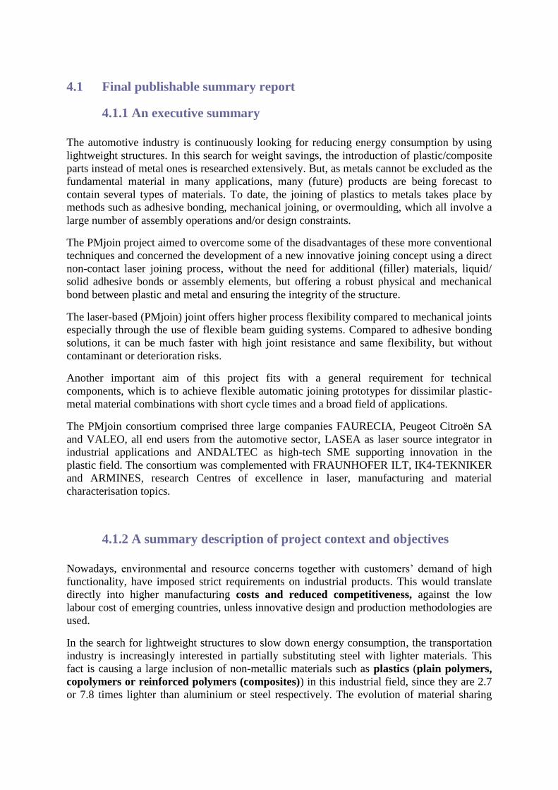
The study 2 performed a similar work but in this case the displacement was applied in “y”
direction simulating a peeling test (Figure 8c) and an imposed movement of 0.16.
As it was expected the peeling forces increased when α angle was increased up to an
asymptotic value (around α =60º). Friction coefficient and Friction Law could have a stronger
impact than the assumed in this study. Therefore friction effect should be studied in deep.
Experimental test need to be done to correlate these results (Figure9)
0,00
0,20
0,40
0,60
0,80
1,00
1,20
0,00 0,20 0,40 0,60 0,80 1,00
Forc
e (
N)
Load Step
Peeling Force
0º
5º
10º
15º
20º
25º
30º
35º
40º
45º0,04
0,39
0,56
0,69
0,81
0,90
0,981,03
1,091,13
0,00
0,20
0,40
0,60
0,80
1,00
1,20
º 20 º 40 º 60 º
Forc
e (
N)
α Angle (º)
Maximum Forces
Maximum Forces
α angle
Figure 9. a) Force vs load step; b) Force vs α angle
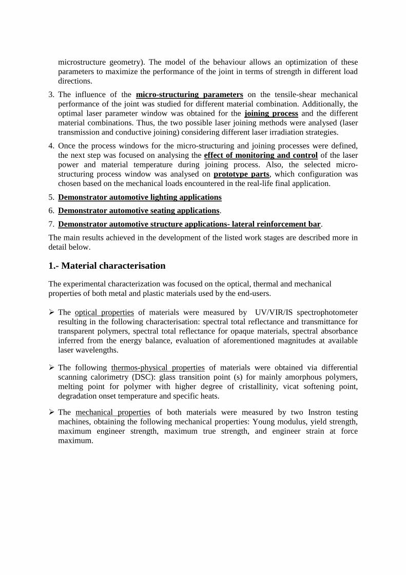
Mechanical modelling of the joint at failure
The objective of modelling consisted in describing the mechanical behaviour of the joining
weld. For that, Arcan-Mines test were performed considering certain groove geometry. Finite
element calculations of the samples allowed to determine a modified Drucker Prager criterion
describing first the plastic yield surface, and secondly the ultimate strength (breaking of the
welded zone). This criterion function of I1, the trace of the stress tensor and J2 the Von Mises
second invariant, is expressed as:
(J2)2 – βR0
2 + I1 (β-1) R0 = 0,
where β and R0 are specific constants depending on the tested material.
In term of application, the objective of this model was to be included in finite element
calculations to design the industrial structures including welded zone which were proposed by
the industrial partners of the project.
A) B)

The first ARCAN-Mines test results were performed on specimens structured with a regular
gap dcc=200 microns. We performed tests for four orientations, at 0°, 30º, 60º and 90°. The
results are plotted in Figure 10. Usually the results of the tests oriented at 0° and 90°, give a
good description of the criteria for all orientations.
Figure 10. Test results on PA-GF30 and steel HC420, at 0° and 90° (broken in the joining plane)
Samples oriented at 30° and 60° are not broken in the join but outside close to anvils.
3.- Fundaments of micro-structuring and joining operations
The main goals of this task were:
To study the feasibility to carry out both processes (micro-structuring and joining
processes) for each material combination using the same laser source.
To study the influence of structuring parameters on the mechanical performance of the
joints.
To study the influence of different laser sources on the micro-structure geometry and
on the mechanical performance of the joints. To assess the influence of different
irradiation methods for the joining operation on the joint's mechanical performance.
The following laser systems were used by the different partners:
Tekniker.
Micro-structuring process: 200CW-Fiber Laser System and Nanosecond Fiber Laser
System.
Joining process: 200CW-Fiber Laser System and 10kW High Power Diode Laser System.
ILT
Micro-structuring process: 1kW single mode fiber laser system.
Joining process: 3kW diode laser system

Andaltec Joining process: 100W Fiber coupled diode laser system.
Lasea
Micro-structuring process: 20W Femtosecond laser and 20W nanosecond pulsed fiber
laser.
Joining process: 200W Fiber coupled diode laser system.
The joint configuration for the micro-structuring and subsequent joining process for each of
the end-user applications was a lap-joint configuration (Figure 11). Different joining tests
performed with different metal structuring patterns and strategies were analysed in terms of
the joint's mechanical performance.
Figure 11. Lap joint configuration
In the case of TEKNIKER the activity was focused on the following stages:
A) First stage: to study the possibility to carry out both operations (microstructuring and
joining) with the same laser system (200W CW Fibre Laser System) and beam delivery optics
to make easier and cheaper the whole process.
Table 1 shows that, in the cases of steel sheets having a thickness lower than 2 mm, it is
possible to conduct the whole process with the same laser system (200W CW fibre laser
system). However, for aluminium and cooper coated sheets high optical power levels are
required during the joining process due to its high reflection percentage at the considered
wavelength (requiring High Power Diode Laser). Likewise, with thicker steel samples 200W
does not generate the enough energy to reach the metal-polymer interface. Furthermore, in the
case of aluminium the micro-structuring process must be carried out by nanosecond pulsed
laser system, allowing getting a successful micro-structuring on this sort of materials with
ablation rates higher than other materials with pulsed wave.

Table 1. Outline of the study of the possibility to carry out both micro-structuring and subsequent
joining operations with the same laser system
Table 2 presents the failure force (Ffailure) achieved during the mechanical shear tests for the
material combinations with possibility to carry out the whole process by the same laser
system.
Table 2. Results of failure force in tensile shear tests and failure mode
B) Second stage: to study the influence of structuring parameters on the tensile-shear
mechanical performance of the joint. The study was conducted on HC420 + PA-GF30. With
this aim, several set of trials were conducted considering the effect of different variables:
geometry (width and depth), structure density (defined as the ratio of structured area to the
overall examined area), clamping pressure and reduction of structuring time.
The main conclusions corresponding to the study are summarized as follows:
- There is a direct correlation between breaking force and aspect ratio (depth/width) of
microstructures. For microstructure patterns conducted by nanosecond pulses, the results
revealed two different regimes depending on the number of scans considered: for Ntracks<10
the breaking forces showed a linear correlation, however for Ntracks>10 the breaking values
tend to achieve a threshold.

- Concerning the effect of structure density: the breaking force of the interface rises with
decreasing the distance between groove centres.
- The joint's mechanical performance is independent of the applied clamping pressure in
the range 0.5-6 bar.
Concerning cycle time: Figure 12 shows the breaking force of HC420+PA-GF30 as a function
of the ablation rate (time required to microstructure 1cm2) for different microstructure
geometries produced by nanosecond laser and CW fibre laser. The higher breaking forces
were achieved when longer ablation rates were considered. It is possible to see that different
breaking forces are found for the same ablation rate by different microstructure parameters.
Figure 12. Failure force of HC420 + PA-GF30 vs ablation rate for different structure geometries
produced by ns laser pulses and CW fibre laser system.
The optimization step was performed in two different ways:
- In the case of micro-structures generated by nanosecond pulses, the focusing lens
used for previous textured patterns were replaced by a lens with shorter focal length. Based on
this, it was possible to obtain the same microstructure pattern by a smaller number of tracks
and thus, shorten the processing time.
- Based on the previous results a new set of trials was carried out considering higher
structure density values and lower number of tracks.
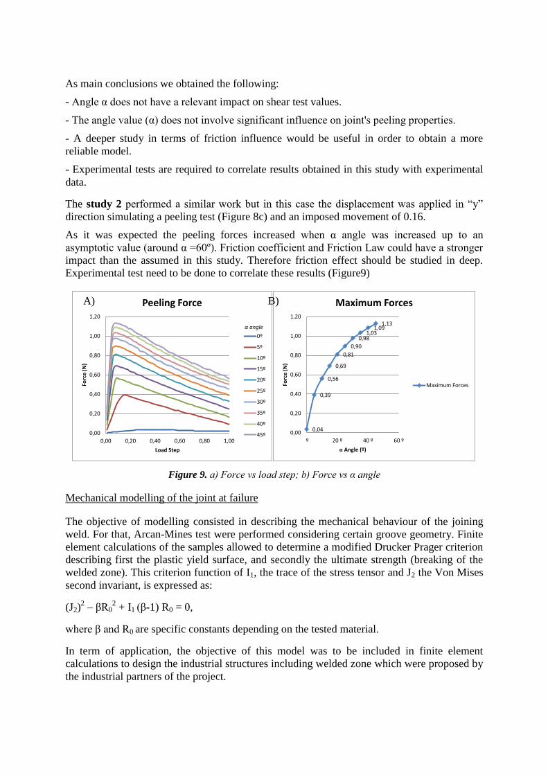
The results (Figure 13) suggest that, in the case of microstructures generated by nanosecond
pulses, for a certain ablation rate T, the time inverted in increasing structure density (dc-c↓) has
higher beneficial effect on the failure force than the time inverted in increasing Ntracks.
However this trend is not clearly evidenced in the case of microstructures generated by CW
laser system.
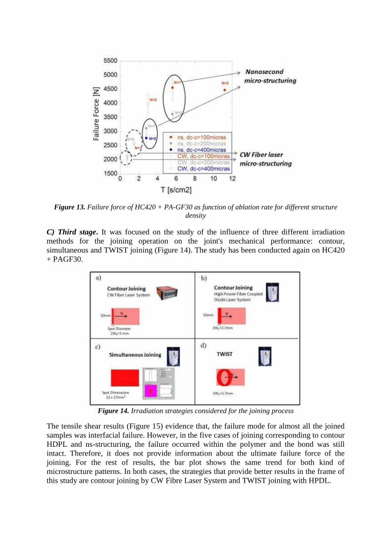
Figure 13. Failure force of HC420 + PA-GF30 as function of ablation rate for different structure
density
C) Third stage. It was focused on the study of the influence of three different irradiation
methods for the joining operation on the joint's mechanical performance: contour,
simultaneous and TWIST joining (Figure 14). The study has been conducted again on HC420
+ PAGF30.
Figure 14. Irradiation strategies considered for the joining process
The tensile shear results (Figure 15) evidence that, the failure mode for almost all the joined
samples was interfacial failure. However, in the five cases of joining corresponding to contour
HDPL and ns-structuring, the failure occurred within the polymer and the bond was still
intact. Therefore, it does not provide information about the ultimate failure force of the
joining. For the rest of results, the bar plot shows the same trend for both kind of
microstructure patterns. In both cases, the strategies that provide better results in the frame of
this study are contour joining by CW Fibre Laser System and TWIST joining with HPDL.

Figure 15. Comparison of ultimate failure force obtained for different irradiation strategies
D) Fourth stage. The activity was focused on the optimization of the joint's mechanical
performance for different metal-plastic combinations of the rest of the applications. The
micro-structuring parameters for the needed pre-treatment along with the suitable parameters
for the joining operation have been chosen based on the results obtained from the previous
stages.
Table 3 shows an overview of the mechanical performance of the plastic-metal joints listed in
Table 1. In the cases of applications 8 (XSG+PA66-GF) and 9 (P260+PA66-GF), the
conductive joining process was carried out by different laser systems for micro-structuring
and joining operations. In the case of XSG+PA66-GF the results in terms of tensile shear
strength are quite similar; the main difference between them is related to the cycle times. For
P260+PA66-GF combination the results reveal a meaningful improvement when the
nanosecond laser and diode laser system are used for structuring and joining operation
respectively. The joined samples Al5182+ PA66-GF (application 11) provided the most
desirable results: the failure took place by polymer yield far away from the interface. The
ultimate failure force (7400N) provides a measurement of the polymer properties. In the case
of Faurecia material combination 7 (HC420+PAGF30) different tensile shear strength values
are found depending on the laser systems used for structuring and joining process.

Appl Mat. Micro-Structuring Joining T.S Strength [MPa]
PSA
8
XSG
+ P
A6
.6-
GF
CW Fiber Laser, P=200W, v=7m/s, Ntracks=2, dcc=100µm CW Fiber Laser. Contour Joining. 12 ± 3
Ns Fiber Laser, P=40W, v=180mm/s,Ntracks=4, dc-c=200µm, τ=250ns Diode Laser System Contour Joining. 11 ± 1
9
P2
60
+ P
A6
.6-G
F CW Fiber Laser, P=200W, v=7m/s Ntracks=2, dc-c=100µm CW Fiber Laser, Contour Joining 16 ± 3
Ns Fiber Laser, P=40W, v=180mm/s, Ntracks=4, dc-c=200µm, τ=250ns CW Fiber Laser, Contour Joining 11.1 ± 4.3
Ns Fiber Laser, P=40W, v=180mm/s, Ntracks=4, dc-c=200µm, τ=250ns Diode Laser System Contour Joining. 27.5 ± 2.4
11 Al5182+ PA6.6-GF
Ns Fiber Laser, P=40W, v=360mm, Ntracks=4, dc-c=200µm, τ=250ns, Diode Laser System, Contour joining >7400
Fau
reci
a
7
HC
42
0 +
PA
-GF3
0 Ns Fiber Laser, P=40W, v=180mm/s, Ntracks=4, dc-c=200µm, τ=250ns Diode Laser System, Contour Joining 18,2 ± 0.5
Ns Fiber Laser, P=40W, v=180mm/s Ntracks=2, dc-c=100µm, τ=250ns, CW Fiber Laser System, Contour Joining 22,4± 0.2
CW Fiber Laser, P=200W, v=7m/s Ntracks=2, dc-c=100µm CW Fiber Laser System, Contour joining 20± 2
An
d.
1 X5 Cr Ni + PC Ns Fiber Laser, P=40W, v=180mm/s, Ntracks=6, dc-c=600µm, τ=250ns, Diode Laser System, Contour Joining > 1320 N
Va
leo
3 Al(SMI)+ PC Ns Fiber Laser, P=40W v=360mm/s, Ntracks=4, dc-c=200µ, , τ=250ns.
Diode Laser System, Contour Joining
> 2700 N
Table 3.- Results of tensile shear strength for the different material combinations
In the case of ILT the laser source used for microstructuring is a water cooled IPG 1000 W
single-mode cw fibre laser. The laser beam is guided through an optical fibre. It is a laser
source which has a very high beam quality. The beam source is portable and of simple
automation, therefore, it can be integrated on different machines, machining centres, robots,
etc. The laser radiation is deflected by a galvanometric scanner to achieve different structure
orientations. The focusing optic has a focal length of 330 mm, having the resulting spot a
radius of 20 µm.
For the microstructuring process the following parameters are varied:
Scan speed v [m/s],
Laser power P [W],
Number of iterations N [#]
Distance between adjacent structures dc-c [µm]
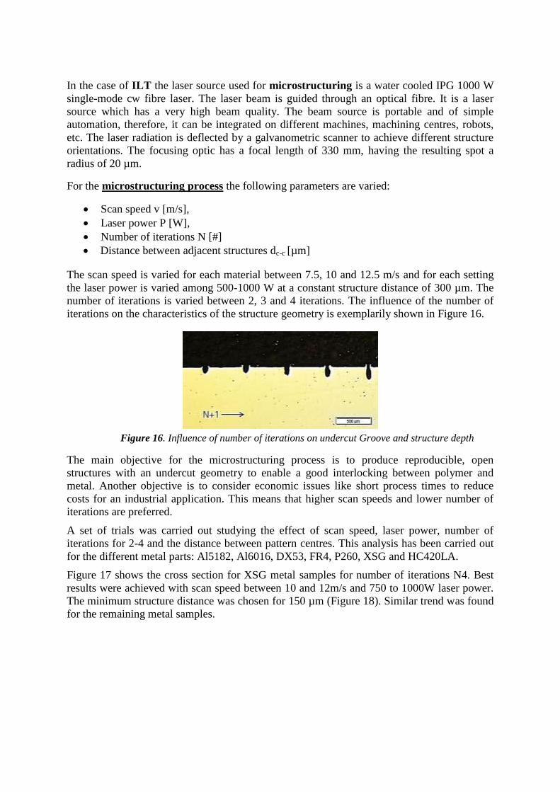
The scan speed is varied for each material between 7.5, 10 and 12.5 m/s and for each setting
the laser power is varied among 500-1000 W at a constant structure distance of 300 µm. The
number of iterations is varied between 2, 3 and 4 iterations. The influence of the number of
iterations on the characteristics of the structure geometry is exemplarily shown in Figure 16.
Figure 16. Influence of number of iterations on undercut Groove and structure depth
The main objective for the microstructuring process is to produce reproducible, open
structures with an undercut geometry to enable a good interlocking between polymer and
metal. Another objective is to consider economic issues like short process times to reduce
costs for an industrial application. This means that higher scan speeds and lower number of
iterations are preferred.
A set of trials was carried out studying the effect of scan speed, laser power, number of
iterations for 2-4 and the distance between pattern centres. This analysis has been carried out
for the different metal parts: Al5182, Al6016, DX53, FR4, P260, XSG and HC420LA.
Figure 17 shows the cross section for XSG metal samples for number of iterations N4. Best
results were achieved with scan speed between 10 and 12m/s and 750 to 1000W laser power.
The minimum structure distance was chosen for 150 µm (Figure 18). Similar trend was found
for the remaining metal samples.
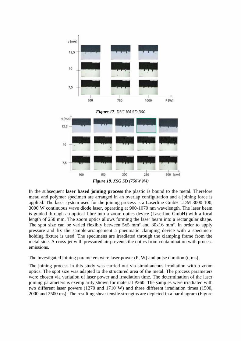
Figure 17. XSG N4 SD 300
Figure 18. XSG SD (750W N4)
In the subsequent laser based joining process the plastic is bound to the metal. Therefore
metal and polymer specimen are arranged in an overlap configuration and a joining force is
applied. The laser system used for the joining process is a Laserline GmbH LDM 3000-100,
3000 W continuous wave diode laser, operating at 900-1070 nm wavelength. The laser beam
is guided through an optical fibre into a zoom optics device (Laserline GmbH) with a focal
length of 250 mm. The zoom optics allows forming the laser beam into a rectangular shape.
The spot size can be varied flexibly between 5x5 mm² and 30x16 mm². In order to apply
pressure and fix the sample-arrangement a pneumatic clamping device with a specimen-
holding fixture is used. The specimens are irradiated through the clamping frame from the
metal side. A cross-jet with pressured air prevents the optics from contamination with process
emissions.
The investigated joining parameters were laser power (P, W) and pulse duration (t, ms).
The joining process in this study was carried out via simultaneous irradiation with a zoom
optics. The spot size was adapted to the structured area of the metal. The process parameters
were chosen via variation of laser power and irradiation time. The determination of the laser
joining parameters is exemplarily shown for material P260. The samples were irradiated with
two different laser powers (1270 and 1710 W) and three different irradiation times (1500,
2000 and 2500 ms). The resulting shear tensile strengths are depicted in a bar diagram (Figure

19a). The joining parameters were chosen by high strength of the connection with low
standard deviation and no decomposition of the material in the joining process.
a) b)
Figure 19. Shear tensile strength testing results of P260
The highest shear tensile strengths were achieved with parameters PF6 and PF5. A cross
section of PF6 shows a formation of bubbles and therefore a decomposition of the polymer
matrix material (see Figure 19b, red marked spots). Thus these conditions cannot be viable for
a durable connection. However, a cross-section of PF5 does not show this kind of
decomposition (Figure 20), therefore this parameter setting was chosen for further joining
tests.
Figure 20. Fractured surface and cross section of hybrid connection for parameter setting PF5
The resulting shear tensile strengths of joining tests are as followed:
HC 420 LA PAGF30 SD 200 µm (L) 19.2 MPa
P260 PA66 woven SD 200 µm (C) 20.5 MPa
XSG PA66 woven SD 200 µm (C) 17.8 MPa
6016 PA66 woven SD 300 µm (L) 12.3 MPa
5182 PA66 woven SD 300 µm (L) 14.1 MPa
FR4 PC SD 200 µm (L) 17.2 MPa
DX53 PPt20 SD 300 µm (L) 16.4 MPa
The research of LASEA was focused on the development of complex designs, taking
advantage of the laser technology used. In a preliminary stage the objective in the task was
based on the determination of the best ratio between micromachined and non-micromachined
surfaces in order to reach the maximal resistance of the joining. These results were used later
on the development of the mentioned complex designs.

In this task, LASEA also focused its research on the determination of the best design ensuring
high tensile resistance for different kind of polymer/metal combinations. The study started by
straight line design in order to observe the behaviour of a polymer/metal joining with a simple
design of microstructures. After some joining tests performed with a 200W fibre guided
laser, a selection of geometrical parameters was done. Once this choice was made, the designs
were performed on all metallic plates and were sent to ANDALTEC to carry out the joining
with their laser equipment.
LASEA continued its study with more complex designs firstly on X5CrNi stainless steel
plates. A first selection of geometrical parameters was performed. After which, a set of 4
identical samples with the same microstructuration design and laser parameters was
manufactured and sent to ANDALTEC for performing the joining and having a statistic study.
After the identification of the most appropriate complex designs, LASEA performed the
design on the other metal plates.
As shown in the Table 4, depending on the combination of polymer/metal joining the design
inducing the highest resistance can vary but in general and for more reflective metals (Al for
example) or the thin metal plates, the complex designs induce higher resistance. In this way,
LASEA with ANDALTEC will patent the methodology followed for reaching complex
designs and the designs inducing high tensile resistance.
The activity carried out by ANDALTEC consisted of an optimization of the joining
parameters to achieve an efficient joining between metal and plastic. The laser used during
this activity is a diode at 980 nm with a maximum output power of 105W. This laser is
mounted on an ABB IRB1600 6 axis robot. The system has the possibility of applying
pressure during operation thanks to a roller dispositive.
Different assays including both polymer-metal transmission and metal-polymer conductive
joining processes were carried out in contour mode. The diameter of the spot was 3.8 mm and
2 welding lines were made in each joining test.
The joining parameters considered during optimization were: robot speed, pressure and
power. Speed was maintained at 1 mm/s (the slowest value possible) and then the power was
optimized within the range 20-100 Watts. Pressure was studied in the range 150-200 mbar.
The joint's mechanical performance was assessed by tensile-shear test by a Universal testing
machine Tinius Olsen.
A comprehensive study of the joint's mechanical performance was conducted based on the
different structure design of Lasea.
The study was carried out for the different material combinations: DX53-PPt20, MnB5-
PAGF30, MnB5-PPGF30, X5-PMMA, P260-PA66Woven, XSG-PA66Woven, DP600-
PPGF30 DP1000-PPGF30 and AL-PC.
Table 4 summaries the highest values of ultimate shear strength reached for each material
combination:

Metal Plastic Shear strength
(N/mm2) Texturing
DX53 PP20t 3.9/3.2 Line design or complex design, nanosecond
MnB5 PAGF30 4.2 Complex design, nanosecond
MnB5 PPGF30 6.5 Line design
X5 PMMA 4.8 Complex design nanosecond
P260 PA66Woven 19.8 Line design
XSG PA66Woven 11.4 Complex design, nanosecond
DP600 PPGF30 7.3 Complex design, nanosecond
DP600 PAGF30 11.4 Line design
DP1000 PPGF30 6.4 Line design
DP1000 PAGF30 12.5 Line design
Al
PC (with
surface
additive)
3.79 Complex design, nanosecond
Table 4. Summary of the best ultimate shear strength reached for each PM join
X5 – PMMA join was the unique case among those tested where plastic material broke before
joining failure. It means joining between X5 and PMMA presents more resistance than
PMMA itself. According to the results there is not a unique solution in terms of texturing.
Depending on the application and plastic material involved there will be one specific
texturing that will be more recommendable to carry out in order to optimize the PM join.
4.-Effect of monitoring on the join quality. Joining process on prototype
parts
The first part of the task concerns the effect of optimizing the joints by process monitoring.
Different approaches developed for monitoring and control of microstructuring and joining
operations are herein summarized. Additionally, the results concerning the joint quality of
representative joining configurations or prototype parts of the final application in the case of
FAURECIA material combination were discussed.
Thermal monitoring
TEKNIKER carried out laser process control through infrared pyrometers and thermal
camera in order to optimize the laser joining process. A close loop power-temperature control
was introduced in order to maintain the temperature uniform along the laser joining seam
tracks. Two devices were used: two colour pyrometer to maintain a uniform temperature on
the irradiated material varying the laser power level during the joining process and an infrared
thermal camera for monitoring the surface temperature map of the irradiated area.

The analysis was conducted on the material combination corresponding to the application 7
(HC420+PA-GF30): conductive joining. The joint's mechanical performance was assessed for
two different joining conditions:
Constant level power P=850W.
T-P control considering a temperature set of 650ºC (data obtained from trials without
T-P control).
Figure 21 illustrates the breaking force values of the polymer-metal join. The results do not
suggest a significant improvement when the T-P control is considered. The results are not
conclusive since the influence of the orientation of fibres prevails over the profit of the
control and besides the length of the joining is very small.
Figure 21. Breaking force of HC420+PA-GF30 joints
Based on previous results, two set of additional trials were carried out:
- the study of the influence of the temperature-power control during the conductive joining
process with longer joining areas (50x20mm2).
- the study of the influence of temperature-power control during laser transmission joining for
the joining areas considered so far (10x20mm2).
But unfortunately in any case, the new results suggested a significant improvement when the
T-P control is considered for the conditions studied at TEKNIKER.
ILT focused on the two following approaches for monitoring the joining process:
Measuring the metal surface temperature for conductive joining process by
infrared camera.
Measuring temperature in interaction zone between polymer and metal by
thermocouples.
To measure the surface temperature, the infrared Camera Optris PI160 is used. The camera
has a wide temperature range from -20°C to 900°C. To measure the temperature in the
interaction zone between polymer and metal a thermocouple is used. For the first
thermocouple experiment the material combination: stainless steel (1.4301, 1 mm) and PC

(Makrolon®, 2 mm) was used. The metal was structured with the following parameters: laser
power 750W, scan speed 10m/s, number of iterations 4, structure distance 300μm.
The whole joining area was irradiated simultaneously by an adaptable zoom optics. The
parameters, laser power and irradiation time, were varied. The thermocouple was positioned
in the middle of the structured area (Figure 22) measuring the maximum joining temperature
in the joining zone. After joining, the specimens were tested by a tensile shear test and the
breaking force determined.
Figure 22. Position of thermocouple
The first joining parameters (510W, 1000ms irradiation time) provided a temperature in the
joining zone of 129ºC. The tensile shear results (521±455N) led a low breaking force and
high standard deviation. The second joining parameters (750 W, 1000 ms irradiation time)
provided a joining temperature of 238ºC. The tensile shear results (1318±98N) led a better
connection strength compared to the first joining parameters. This set up is quite easy to
establish and the components are quite cheap. Because of this it is very suitable for industrial
applications to find out good joining parameters for any material combination.
If the thermocouple is connected to a data logger, the temperature profile can be recorded.
This set-up was tested for FAURECIA material combination (HC420LA + PAGF30). The
thermocouple was positioned in the middle of the structured area, where the highest
temperature was expected. The results showed that the temperature profile is a very important
parameter to evaluate the gap bridging ability. By a longer period in which the melting
temperature is exceeded, a bigger polymer volume is molten and can be used to bridge a gap.
On the other hand ANDALTEC used a Gentec-eo flash handheld probe (FLASH-500-55) in
order to avoid differences between the real emitted and configured power. The goal was to
control the proper melting of the polymer and also to avoid the plastic thermal degradation by
using thermal sensor and Data Logger, temperature control system (label and heat sticks) to
monitoring a range of temperature from 204°C to 260°C.
The heat sticks were used to monitor the degradation temperature of some selected polymers:
253°C, 399°C and 300°C for PPt20, PMMA and PC respectively.
Additionally, like ILT, Andaltec set thermal sensors between plastic and metal samples. The
sensors collect the temperature values and send the information to a data logger in order to
study the joining process. As one representative example, the results obtained during the

joining between some DX53 metal plates with black PP 20% talc plastic samples are
presented (Figure 23a).
a) b)
Figure 23. Thermal sensor between a DX53 metal plate and a PP 20% talc plastic sample
Figure 23b discloses one example of the evolution of the temperature during a test. The
maximum thermal value reached is 211.2 °C which is below the degradation temperature
determined by Differential Scanning Calorimetry (DSC).
Joining process on Prototype parts
ILT manufactured and tested different specimens to find out the joint behaviour under
different load orientation with the FAURECIA´s material combination (PA6-GF30 +
HC420LA). The evaluation of these prototype parts is needed for the construction of the final
demonstration parts. The different test specimens are shown in figure 24.
Figure 24. Tested specimen to evaluate the bond behaviour under different load directions
Several parameters were varied to find out the influence on the resulting bond strength within
the microstructuring process: laser power, scan speed, number of iterations (N), distance
between cavities (dc-c), structure orientation (lateral, parallel and crossed) and angle of
incidence (θ). In summary the highest shear load was found for:
▪ Shear tension tests: N=4, θ=90º, dc-c=200μm
▪ Tensile tests: N=4, θ=45º, dc-c=200μm and linear, perpendicular orientation

▪ Peel and bending peel tests: they did no provided satisfying results. The maximum force
under given experimental setup was not more than 400N. Thus, the peel forces should be
avoided by the design.
TEKNIKER also manufactured and tested T prototype joined parts (Figure 25a), micro-
structuring the metal with a different laser source emitting in the ns range in order to simulate
the tensile or pull out force (Figure 25b) and to compare the results with those from ILT.
a) b) c)
Figure 25. a) Schematic T configuration; b) Pull test scheme; c) microstructures parameters
A comprehensive design of experiments was performed with the following micro-structure
parameters (Figure 25c):
▪ Number of tracks: Ntracks=2, 4, directly related to the groove depth and width.
▪ Distance between groove centres: dc-c=200, 600µm.
▪ Alignment angle of the grooves θ=45º, 90º.
▪ Direction of structuring: longitudinal and transversal lines.
Concerning the joining process, contour strategy was considered using the CW Fibre Laser
System and the following parameters: laser power 74W, joining speed 6mm/s, clamping
pressure 3bar and spot diameter 1mm. The mechanical resistance of T-joints were checked by
pull tests (Figure25b) considering two different polyamide thickness: 2.5 and 4mm.
The results revealed similar trends for the two polyamide thicknesses. In general terms, high
values of standard deviation were found, ranging from 8% to 40%. It could be related to the
small values of the contact areas. Furthermore, the following trends were identified:
▪ Clear influence of dc-c: 200 6003m m
▪ There is no evidence of influence of structuring orientation (transversal or longitudinal) on
the T-joints mechanical performance.
▪ An increase of the joint strength of about 27% was revealed for deeper grooves compared
to shallower ones, keeping the remaining microstructure parameters constant.
▪ The influence of cavity angles θ, for a certain Ntracks, was negligible.
It can be concluded that the evolution of results with different lasers is quite similar,
demonstrating the robustness of this kind of hybrid joining technology.

5.- Demonstrator: automotive lighting applications
This demonstrator, developed among VALEO, TEKNIKER, LASEA and ANDALTEC,
consists of the assembly of the bulbholder of the rearlamp of the Renault Twingo. This
rearlamp is a product manufactured by VALEO. The laser joining process is expected to be
tested as alternative to the stamping + riveting process currently in use. Thus, the metal circuit
of the bulbholder was joined to the plastic body by means of laser joining technology. The
metal circuit is made of steel DX53 and the plastic of grey PP with 20% of talc.
Figure 26. a) Renaul Twingo; b) Rearlamp, front side; c) Rearlamp, back side with bulbholder
Figure 27 a) and b) show a bulbholder with the riveted circuit (currently in use) and a
bulbholder joined by laser respectively.
Figure 27. a) Bulholder with the riveted circuit; b)Bulbholder with the circuit joined by laser
After removing the pins and texturing metal circuit both plastic and metal parts were totally
ready to carry out the PMjoin process. The texturing was carried out by TEKNIKER and
LASEA and the joining process mainly by ANDALTEC.
Texturing by TEKNIKER (T3):
A previous stage focused on selecting the optimum microstructuring parameters allowed to
reach a balance between joint's mechanical performance and process time with continuous
fibre laser system and following parameters: :
- Laser Power 200W
- Scanning speed v=7m/s.
- Distance between groove centres: 150 µm
Texturing by LASEA (T2):
LASEA textured the metal circuits by using a nanosecond pulsed fibre laser to generate a
complex design:
- Laser Power 50W
- Pulse duration=100ns.

Laser joining process
This process was conducted by ANDALTEC with T2 and T3 conditions and to a lesser extent
by TEKNIKER with only T3 condition. The main reason to conduct some joining trials at
TEKNIKER was to analyze the feasibility to carried out the whole process (structuring and
joining process) using a unique laser source.
Pins sinking test at ANDALTEC
The Pins sinking test defines the effort exerted on the pins of the circuit when the connector is
assembled. The necessary force to sink the pins of the metal circuit in the plastic housing is
tested by pushing all the pins at the same time. The minimum load capacity set by automotive
manufacturers is 80N, considered as a minimum threshold load value to select the optimum
microstructuring condition.
The results showed that only the texture T2 from TEKNIKER and the case of high power and
small number of passes from LASEA fulfilled the requirements in terms of loading (>80N).
Figure28 shows a circuit textured by TEKNIKER. LASEA performed complex design on the
metal part (but due to the desire of LASEA and ANDALTEC to protect the design, no image
is showed here).
Figure 28. Textured Circuit by Tekniker
Based on the previous results, 50 metallic circuits were structured by the two set of
microstructuring parameters by both LASEA and TEKNIKER and sent to ANDALTEC for
the subsequent joining and validation operations
Validation plan
The validation plan was focused on elucidating by means of several tests the behaviour of the
joined parts in those conditions that a bulbholder could suffer throughout its useful life.
Those tests carried out to validate the joining were selected based on end-users requirements.
Specifically, the tests were chosen by studying thoroughly the VALEO standard validation
plan for rear lamps. According to the bulbholder requirements and applications it was
considered that the validation plan had to be based on the study of the following properties:
mechanical strength, electrical behaviour, thermal resistance and physico-chemical properties.
According to this, the tests which were included in the validation plan are listed below:
A. Pins sinking.
B. Resistance to fitting and removal.
C. Voltage drops.
D. Drop test resistance.
E. Resistance to heat with bulbs switched on.

F. Resistance to climatic cycling.
G. Behaviour in humid air.
H. Corrosion resistance.
All the tests of the validation plan for bulbholder demonstrator were carried out in
ANDALTEC facilities.
The validation plan was developed with bulbholders and complete rear lamps (Figure 29).
Some tests need to be done with the complete rear lamp because it reproduces real situations.
Figure 29. Bulbholder welded by laser with gasket and bulbs.
Conclusions:
▪ All the bulbholders passed the tests. Therefore any shortcoming was found in terms of
functionality preventing of dissuading the technology application in real parts.
▪ The Table 5 below shows a summary of the tests that have been carried out to develop the
validation plan.
Table 5. Summary of the validation plan results

6.- Demonstrator: automotive seating applications
Design/ description of the demonstrator
The concept of the FAURECIA automotive backrest seat structure demonstrator is shown in
Figure 30. Starting from an original steel backrest, the upper and lower cross-members, i.e.
horizontal parts in Figure 30, are kept as they are, but the left and right steel side-members,
i.e. the vertical parts in Figure 30 are replaced by composite side-members.
Figure 30. Concept of Faurecia seat backrest demonstrator
Performance evaluation of PMjoin process
FAURECIA carried out a detailed investigation into the process variables that influence the
mechanical performance of the joint, i.e. tensile shear (following DIN EN 1465 for testing
glued plastic parts), tensile pull (where there is no existing testing standard) and peel strength
(DIN EN 28510 part 1 for testing glued plastic parts). The work was done in collaboration
with TEKNIKER and ILT, where all samples were structured and joined.
In addition to the tensile shear tests done at room temperature, FAURECIA has also done
additional climate chamber tests at -35˚C and +85 ˚C to determine the strength of the joints
when using seats in different parts of the world. Likewise FAURECIA has done testing to
determine the influence of humidity and a corrosive atmosphere on the mechanical
performance of the PMjoin assembly. Finally the influence of the surface condition of the
metal sample and the storage of the structured parts has also been analysed, showing a loss of
mechanical strength of between 10 and 30% under the more aggressive conditions, meaning
that safety factors are needed in the PMjoin design.
Manufacturing the demonstrators
For the structuring process, the same parameters were used for all joints by ILT. The
parameters used are shown in the table below. The output power used was 750W.
Number of repetitions Angle of cavity Distance between
cavities Type of structure
N4 90° / 0° 200 µm linear

For the structuring, only linear structures were used. In some areas of the backrest, this led to
structures under an angle, as shown in Figure 31.
Figure 31. Example of a structured area of the upper cross-member with angular offset
In total, twelve different joining areas were necessary for a complete backrest.
For the joining process, in a first step the recliners with mobile gusset sub-assemblies (which
were welded beforehand at FAURECIA using conventional steel-steel laser welding) were
joined with the composite side-members. The schematic setup of the parts inside jig is shown
in Figure 32.
Figure 32. Joining the boomerang subassembly
The contour welding process was applied and for each of the areas, the zoom optic was
adjusted to focus 1000W of power into the maximum spot size available (30x16 mm²). The
weld speed was adjusted for the mobile gusset to side-member joints, because of the thickness
of the mobile gusset. To compensate the reduced heat conduction at the beginning of each
joining step, the velocity of the laser radiation was also reduced for a few seconds.
Assembly
In the last step of the manufacturing process, the PMjoin backrest was assembled to the steel
cushion structure to get a complete seat structure for the validation (Figure 33).

Figure 33. a) Full seat demonstrator. Figure b) Hybrid-backrest with suspension mat
In addition, a suspension mat, foam padding and seat covers were assembled, to ensure the
correct positioning of the 95% dummy onto the seat for testing.
Seating validation tests
Two static tests and one dynamic test were performed. The static tests (Figure 34 and Figure
35) are to understand the behaviour of the seat in the event of a front and a rear crash. Both
tests give a quantitative result, i.e. at what torque or at what force does the seat fail and how
does a failure unfold? In contrast, the dynamic crash test shows what happens in real-life and
gives a pass or fail report.
Static rear crash
Figure 34 below shows the set-up and a sequence of stills taken during the static rear test for
one of the demonstrators tested.
Figure 34. Static rear test stills
The first of the tested structures failed in a-symmetrical way, with only the right gusset-to-
side-member joint surviving the test. The left gusset was torn clean off the composite side-
member. The latter was also the failure seen on both sides of the second backrest that was
tested.

The torque recorded for the first tested backrest reached a maximum value of 1086Nm. The
second one failed at a maximum torque of only 534Nm. Although the results do not match
that of an all-steel structure, where the maximum torque recorded was close to 3000Nm, the
behaviour shows promise. The premature failure was contributed to the variability of the
conductive joining step of the PMjoin technique. If both sides of the structure were to perform
in a similar way as the right hand side of the first tested structure, the maximum torque would
have been higher. For that, a reliable closed-loop temperature-based feedback and a non-
destructive test need to be developed.
Static front crash
Figure 35 below shows the set-up for the static front crash test.
Figure 35. Static front test set-up
The top cross-member in both cases broke clean off the rest of the backrest assembly. In
addition to this, the joint at the lower (cross-member) back side also failed on both left and
right hand side of the backrest, except for one side (RH) which was intact after the test of the
second demonstrator. Closer inspection of the top cross-member joints shows how well the
plastic had melted into the grooves. However, in some places there was also evidence of the
plastic having been burnt, indicating overheating of the joint during the conductive joining
step. Again, this shows the need for reliable closed-loop temperature-based feedback (and a
non-destructive test for after the joining operation).
The maximum forces achieved for the two PMjoin demonstrators were 1.95 and 2.8kN,
compared with 4.05kN for an all-steel backrest. It is noteworthy that the all-steel structure
performed exceptionally well, with the maximum force for a steel structure typically
averaging around 3.2kN.
This means that for the static front crash test, one of the developed hybrid backrests achieved
89% of the steel version. Despite this very good result, the failure mode, i.e. the top cross-
member breaking off clean, is unacceptable. This is, of course, related to stiffness of the
composite side-members, as the steel equivalents absorb the pull load better as they bend.
Further investigation into an improved design giving more flexibility during crash, is the
recommended step here.
Dynamic rear crash
From the footage can be seen that the PMjoin backrest structure failed in the same a-
symmetrical way as recorded for the rear static test of one of the tested PMjoin backrests. The

tests show that the left gusset-to-side-member (front one) failed, whereas the right gusset-to-
side-member (one at the far end from the camera) survived the crash.
Conclusions for the seating demonstrator
The results achieved confirm the technical feasibility of the PMjoin technique. Overall, the
results are positive, but further work is needed to bring this technique onto the shop floor. In
particular, the following further steps are to be considered:
▪ Redesign of the backrest to optimise the advantages offered by the PMjoin technique,
thereby focussing in particular on:
o 2D joints: efficient clamping of a 3D joint during the conductive joining step
will be challenging in a serial production environment.
o Avoiding peel loads: as confirmed by the coupon testing, the peel performance
of the PMjoin technique remains low.
o Flexibility: the failure mode of the hybrid backrest is different from an all-steel
structure and is determined by the rigid behaviour of the composite side-
members; ways are to be explored to create a certain amount of flexing in the
structure.
▪ The uncertainty of the conductive joining step was obvious from the testing of the seating
demonstrator. The development of a reliable closed-loop temperature-based feedback is a
recommended. In addition, a non-destructive test methodology needs to be developed to
guarantee the joint quality.
7 Demonstrator: structure application-lateral reinforcement bar
The PSA demonstrator evaluates the hybrid joint between a metallic car door and a composite
reinforcement bar. The demonstrator is a protection part in case of a lateral crash.
The main requirements for side impact beam are:
lateral crash requirement
painting process compatibility
compatible with large scale production rates
recyclability
The reinforcement bar consists of a biaxial orientated glass fabric sheet, which is embedded in
a PA6.6 matrix. The thickness of the material is 1.5 mm. There are two joining areas on the
metallic door. The metal material of the first areas A and B is P260 (Hinge side, thickness
1.76 mm), the second material for area C is XSG (Internal panel side, thickness 0.67 mm).
The joining task is shown in Figure 36. Currently the reinforcement bar is joined with metallic
inserts via spot welding. The influence of a more homogeneous power transmission enabled
by the PMJoin approach on the joint performance has been investigated.
Furthermore for crash tests only a subset of the demonstrator was joined and validated. This
subset consists of the reinforcement bar and the reinforcement hinge on the hinge side of the
door.

PM-Join Demonstration Part
Joining Task
Material combinat ions:
Body steels: P260 (t=1.76 mm), XSG (t=0.67 mm)
Composite: PA6.6 / Biaxial glass fabric (0°/90°) (t=1.5 mm)
Internal panel side
Material XSG
Hinge side
Material P260
Reinforcement bar
Door
A
B C
Figure 36. PSA demonstrator
The requirements for the joining areas were defined by PSA to compare the results with spot
welding. For both joining zones on the hinge side (A and B), there is a required tensile shear
force of 6710 N. For internal panel side (C), the required tensile shear force is 2*3900 N =
7800 N (for the two spot welds).
Microstructuring process
The laser source used for microstructuring is a water cooled IPG 1000 W single-mode cw
fibre laser. The laser beam is guided through an optical fibre. For the considered materials
(P260 and XSG) a comprehensive study was conducted considering different microstructuring
parameters being finally selected the following two set of microstructuring options:
Texturation A: P=750W, v=12.5m/s, dc-c=300μm, N4, crossed.
Texturation B: P=1000W, v=12.5m/s, dc-c=300μm, N4, crossed.
The structured surfaces and the corresponding processing times are depicted in Figure 37.
Figure 37. Processed surfaces on metallic door
Joining process
The laser system used for the joining process is a Laserline GmbH LDM 3000-100, 3000 W
cw diode laser, operating at 900-1070 nm wavelength. The laser beam is guided through an
optical fibre into a zoom optics device (Laserline GmbH) with a focal length of 250 mm. The
selected joining parameters are showed in Figure 38.

Figure 38. Joining parameters for demonstration parts
The quantity of joined complete doors and subsets are summarized in Table 6.
Table 6. Quantity of joined complete doors and subsets for validation tests at PSA
Validation plan
The validation plan of PSA consists of three different types of tests:
The first one is a lateral crash test, which was done with complete doors and the subsets
with two different microstructuring parameters (named A and B) and two different
joining areas (named big and small). For each set-up 3 doors and 3 subsets were be
tested with only one exception.
The second test is a door slamming durability test to validate the cyclically and long
time performance of the joint. The door was opened and closed cyclically. The joint
passes the test, if there is still a connection at the end. For this test, two doors were
delivered to PSA. Slamming durability test was carried out on a vehicle: 100,000 cycles
were realized and the holding of the assembling be observed every 5,000 cycles.
The last test is a thermal differential dilatation test to simulate the painting shop
crossing. One complete door is subjected to electrophoresis. The demonstrator is heated
to a maximum temperature of 210°C during 30 minutes.

Crash test results
-Results of door sub-system crash test
To see any shifting of the reinforcement, a reference was marked.
For all doors, the reinforcement shifted in his position between the reinforcement and the door
skin; proof of the joining rupture after the crash test (Figure 39).
Figure 39. Door subsystem before and after the crash, shifting of the composite reinforcement
As conclusion:
A good global behaviour of the door subsystem was observed
The target was not achieved because no joining rupture are tolerated
The joining broke but after the cracks of composite
-Results of partial sub-system crash test
All laser joining had a rupture with a disjoining of the composite with no more polymer in the
texturing. The test showed a solicitation of the joining in tensile shear and tensile pure.
On the diagram (Figure 40), the different tests showed that the texturing B and the greater
surface had the best result. The maximal strength of laser joining was definitely below the
maximal strength of spot welding. An increase of the joining surface improved the
mechanical behaviour of the laser joining. An extrapolation allows us to expect to achieve the
target (spot welding).
Figure 40. Rupture limit for different kind of texturing and joining surface

-Slamming fatigue test results
The slamming fatigue was performed on two doors. The test finished without seeing any
breaking on the joining area and no disjoining (Figure 41).
Figure 41. Visual inspection in the cut out windows
Conclusions:
The laser based joining process is robust due to mechanical interlocking.
Good tensile shear strengths for both PSA material combinations were achieved in the case of
P260 20.5 N/mm²
XSG 17.8 N/mm²
Demonstrator mechanical behaviour
Crash test
• The global mechanical behaviour of laser join should be good in coherence with
join surface
• The maximal strength of the joins on the demonstrator are too low to valid the
concept
Slamming Fatigue test
• No disjoining observed during the slamming fatigue test
The mechanical behaviour of PSA demonstrator is not as good as needed, but a good
perspective is expected with a adapted design to achieve the joining surface target.

4.1.4 The potential impact (including the socio-economic impact and
the wider societal implications of the project so far) and the main
dissemination activities and exploitation of results
General impact
Although the PMjoin technique was developed and demonstrated for automotive applications
only, it can be applied to any industry investigating the advantages of plastic-metal hybrid
components, such as for instance the electronics or aerospace industries.
The main impact of the present project is related to the introduction of lightweight
components in the automotive sector directly affecting the Environmental sustainability of
vehicles and reducing the resource consumption and waste generation, through the
minimization of fuel consumption and its indirect emissions. This fact is aligned with the
Regulation (EU) No 333/2014 of the European Parliament and of the Council of 11
March 2014 amending Regulation (EC) No 443/2009 to define the modalities for reaching
the 2020 target to reduce CO2 emissions from new passenger cars. The project helps to the
replacement of some steel parts by plastics or composites, besides the use of clean laser
methods to join these plastic parts with remaining metal parts avoiding contaminant adhesives
and associated volatile emission of traditional adhesive methods or assembly elements of
traditional mechanical methods.
By the use of hybrid materials (plastic-metal) savings in weight of 40% and more could be
achieved for some components. For instance, the introduction of the composite PA-66 + glass
fabric 50%vol., allows the reduction of 40% in mass of the lateral reinforcement bar of the
door (compared with steel).
In particular, the use of pure steel alloy materials can be reduced which facilitates the weight
saving in automotive parts.
In this context, it must be mentioned that during the last years, the evolution of mass in
European vehicles has risen gradually. The reason has been the integration of new products
and devices in the passive safety, comfort, performance and equipment (ABS, air
conditioning, etc.) and also increment of the vehicle size. However, the mass evolution in
PSA vehicles, for instance, has shown a slight decrease since 2009, as shown in Figure 42,
and the tendency is clearly to continue. Nowadays, the priority is to reduce the mass of each
new vehicle and it is considered as an environmental imperative (according to the Corporate
Average Fuel Economy CAFE 2020) to achieve reduction of (80-100) kg in mass
immediately and 100 kg in the next 10 years. Thus, the replacement of certain steel parts of
the vehicle by plastic composites goes in this line. In fact, Peugeot has reduced 100 kg in the
model 208/207 and 140 kg in the new 308 reaching the challenge of CO2 emissions of less
than 95 g/km by 2020. It is estimated that a reduction in mass of 110kg corresponds to a save
of 5g of CO2. So the target in Peugeot is to have reached a reduction of 110 Kg in 2015 and a
reduction of 220Kg in 2017/18.

Figure 42. New downward tendency in mass evolution of Peugeot and Citroën vehicles
PSA also asserts that there is a lot of room for composite materials by replacing steel
especially in chassis suspension and body in white. For cost and technology reason, « 2020 »
cars will be designed with a mix of steels, aluminium and plastics / composites. This fact is
pushing Tiers 1 like Faurecia and Valeo to move in the same direction.
This project will impact on a sustainable Road transport (represented by Faurecia, Valeo and
PSA partners), one of the major sectors of European industry, manufacturing over a third of
all passenger cars produced worldwide (750 millions cars). According to Eurostat, the
transport industry directly employs more than 10 million people, accounting for 4.5% of total
employment, and represents 4.6% of GDP (EU’s Gross Domestic Product). Manufacture of
transport equipment provides an additional 1.7% GDP and 1.5% employment.
Another remarkable impact comes from the Economical sustainability of manufacturing,
through the reduction in the number of manufacturing steps; mechanical interconnects and
manufacturing operations by means of the development of more simple products.
New skills in the European workforce resulting also in indirect socio-economic benefits; the incorporation of this novel joining alternative in an industrial scenario entails the capture
of new abilities by end-users. Dissemination tasks included in this project have transferred the
acquired knowledge into several manufacturing sectors that can also benefit from this
technology. Thus the impact will spread out the Manufacturing Sector. Manufacturing is
still the driving force of the European economy. The manufacturing industry produces
approximately 80 % of the EU’s exports – worth about €1.8 trillion in 2013. It involves
around 2 million enterprises largely dominated by SMEs across the EU, employs about 30
million people directly (and another 40-60 million indirectly) contributing 15.1% of GDP.
There are 10 Project Results (Table 7) which have commercial/social significance in this
automotive market and can be exploited as a stand-alone product, process, service, although
some of them might need after the project further R&D, prototyping, engineering, validation
etc… before they become commercially exploitable.

N. Exploitable
results Description
Partners
involved
Impact
1
MODEL
FEM Thermal
simulation model
of the laser PM
laser joining
process
A method able to predict
the optimum laser joining
process parameters that
yield the required polymer
melting temperature and
the joining strategy, and
therefore to reduce the
number of field tests.
TEKNIKER
The possibility of reducing
the time and improving
quality of the joining
process of different
polymer-metal joining
applications
2
MODEL
Simulation model
of the mechanical
behaviour of the
PMjoining
A method to characterize
the mechanical
performance of the
PMjoining in correlation
with the laser process and
the structuring parameters.
The proposed model of the
behaviour allows an
optimization of these
parameters to maximize
the performance of the join
in term of strength and
durability.
ILT, ARMINES
The possibility of reducing
the time and improving
quality of the joining
process, by simulation-
optimisation of the process
to maximise the joint
performance to be in line
with the application
requirements
3
PROCESS
Efficient Laser
microstructuring of
metal surfaces
A process for structuring
metal surfaces using a
laser, able to improve the
polymer anchorage to the
metal part during the
joining activities
All
Innovative microstructures
to help the anchorage of
melted polymer material.
4
PROCESS
Laser transmission
joining of PM
components (Valeo
application n. 3)
Method for laser joining of
metals and laser
transparent polymers.
ANDALTEC,
ILT, LASEA,
TEKNIKER
Replacement of metal
screws by weld points in
different parts of
structures; environmental
friendly process
5
PROCESS
Laser conductive
joining of plastic-
metal components
(other applications
collected in D1.1)
Method for laser joining of
metals and laser opaque
polymers.
TEKNIKER,
ANDALTEC,ILT,
LASEA
Replacement of metal by
plastic in different parts of
structures; environmental
friendly process

6
Demonstrator for
laser PMjoining of
automotive lighting
applications. App
2: Electric circuit
board onto PP bulb
holder
Implement laser assembly
solution into lighting
module production.
TEKNIKER,
ANDALTEC,
VALEO, LASEA
Efficiency through
automation of the
assembly of dissimilar
parts
7
Demonstrator for
laser PMjoining of
automotive lighting
applications. App
3: LED board on
reflector
Integrate laser assembly
solution into LED
Lighting module
production by overtaking
screwing process in
efficiency and
repeatability and cost.
Through dedicated
assembly lines, target is to
have equipment able to
produce 1 million modules
per year.
LASEA,VALEO,
ANDALTEC
Replacement of metal
screws by weld points in
different parts of
structures; environmental
friendly process
8
Demonstrator for
laser PMjoining of
automotive
structure
applications.
Lateral
reinforcement bar
Implement the PMjoin
process in applications
defined by PSA.
ILT,
PSA
Lighter and more
environmental friendly car
9
Demonstrator for
laser PMjoining of
automotive seating
applications
An approach to
assembling metal to
composite backrest seat
structures using the
PMjoin methodology.
FAURECIA
Lighter and slimmer seat
BR structures
10
PROCESS
Efficient Laser
microstructuring of
metal surfaces with
complex “bio-
inspired” textures
A process for preparing
metal surfaces, able to
improve the polymer
anchorage to the metal part
during the joining
activities base on the use
of complex structures..
ANDALTEC,
LASEA
Thinner metal plates that
could be deformed in case
of using CW or high
power lasers and/or very
reflective metal substrates,
like but not only,
aluminium and copper
alloys.
Table 7. Project results
In the PMjoin project, four demonstrators were built using the knowledge gained through the
project, all of which were related to the automotive sector.

Detailed Impact on developed demonstrators
- Demonstrator 1a for automotive lighting applications: Electric circuit board onto PP bulb
holder
Reduction of manufacturing costs because of the removal of manufacturing steps and
scrap reduction
Riveting involves 3 stations: heating, riveting + cutting and control where heating limits
the production cycle to 70 s. With the new laser joining alternative this time is expected to
shorten to 30s and the production rate to increase from 103 parts/h to 240 p/h giving cost
savings about 57% per part that means 45000 €/year.
New bulbholder designs will have less design constrains thanks to this new joining
technology.
- Demonstrator 1b for automotive lighting applications: LED board on reflector
Increased overall quality in terms of repetitively, tolerances, photometric properties and
scrap.
For example an annual production of Audi A6 consists of c.a. 40000 cars/year. The cost of
each rear lamp is around 40€. If scrap could be reduced from 6% to 2% through the
implementation of the expected PMjoin technology, this could save around 0.8 € per each
rear lamp. Therefore the total saving per car ranges 1.6 € and for all cars 64000 €/year
total saving costs can be obtained.
- Demonstrator 3 for laser PMjoin of automotive seating applications
At the moment, no plastic-to-metal backrest structures are in existence within Faurecia’s
seating division. However, the results from the PMjoin project have shown the potential of the
laser-based micro-structuring and (conductive) joining technique. The backrest structure was
chosen as a demonstrator as it is a highly visible product within the company and its potential
customers. It is still some time however, before a multi-material structure as the one
represented by the seating demonstrator, will find its way into a high volume serial
production. Nevertheless, there are a range of (less ‘visible’) subassemblies of the seat
structure where the combination of steel with plastic/composite has a technical as well as a
commercial advantage. For these subassemblies, the time to market is considerably shorter,
and business cases will be prepared for these subassemblies o be manufactured using the
PMjoin technology. Through a gradual introduction of the PMjoin technology for plastic-
metal joining, it is estimated that the technique will contribute to a weight saving, compared
with a current all-steel seat structure, of between 5 and 10% by 2020. For a more general
acceptance in the automotive industry of composite as a replacement of steel components, the
cost of the (manufacturing of the) composite alternative still has a long way to go.
Cost impacts
For Demonstrator 1 the operating cost for the PMjoin process is higher than those obtained
for the current process. Nevertheless the laser joining is better in terms of tooling cost. For
this application it can be concluded that is not recommended to use the new process under the
given scenario.

In the case of Demonstrator 2, the current process is more cost-efficient than the PMjoin one.
The main reason is the high equipment cost of the PMjoin approach. By increasing the
number of units per year this could be minimized. In addition is worthy to mention that for
this case the time cycle for PMjoin process is shorter than the current one.
The total operating cost for Demonstrator 3 (without labour) is close to 7 times higher than
the current manufacturing cycle, taking into account only the operations that are different. The
use of a multi-cavity tool for injection-moulding and a different heat source for the conductive
joining (e.g. induction) should be considered to bring this cost down. Nonetheless, in the short
term, the cost of a PMjoin based technology for serial production of hybrid backrests will
remain much higher than the conventional manufacturing, so this will have to be offset
against other advantages the hybrid backrest offers, such as weight saving or improved design
flexibility (compared with steel side-members).
As an overall conclusion, the total operation cost is higher for the PMjoin process in
comparison with the current joining technologies for the demonstrators developed in this
project. Some additional efforts will be essential to facilitate the industrialization of the
developed process. With the cost study, the PMjoin project has already identified some
improvement areas, which can be summarized as follows:
Redesign the new part specifically to suit this new joining technology. In this way, we
could save material and achieve a significant reduction of the time cycle.
Increasing the number of parts to be manufactured. In order to reduce the negative
effect in the analysis of the high equipment amortization costs.
The technology is only in the beginning and high improvement opportunities exist for
reducing the manufacturing cost such as automation and tooling improvements.
In the case of PSA and Faurecia, one of the main limitations is the investment in new
equipment. This could be minimized by increasing the units/year rate.
Environmental impacts
In the case of Demonstrator 1, the environmental impact is quite similar between the current
joining process of riveting and stamping and the PMjoin process but any of the parts have
been adapted to the new process. Nevertheless the new laser plastic-metal joining process
requires less mechanical effort than the current joining processes, so the plastic and metal
parts are probably oversized. So a redesign of these two parts would improve the new PMjoin
processes’ environmental impact.
In the case of Demonstrator 2, there is an impressive environmental impact reduction with the
new PMjoin process (87% of decrease) in comparison to steel-steel spot welding where the
cutting of the holes in the bar and the introduction of inserts widely worsen this factor.
Moreover, the decrease takes place in all environmental aspects. The biggest impact reduction
is obviously detected in the metal depletion, coming from removing the mild steel insert
manufacturing step and energy consumption coming from the avoidance of the water jet
cutting process. Other positive effects are relevant on: Climate Change affecting Human
health and Ecosystems, Human toxicity, Particulate matter and fossil depletion.
In the case of Demonstrator 3, the total environmental impact of the new PMjoin process is
almost similar to the environmental impact of the current process. But, it is observed that

depending on the impact category, the environmental impact of each process is more
favourable: while in the new PMjoin process the impacts in the fossil depletion or climate
change (human health) are more important, the current process affects much more in the metal
depletion category, human toxicity and particulate matter. Nevertheless the higher difference
on environmental categories (taking into account both processes) is logically in the metal
depletion. At this point, it is worth mentioning that the environmental impact of the joining
steps in an isolated way decreases with the PMjoin process: in the current process, the impact
reached a 3.83 % (‘welding’) and in the new PMjoin process the impact is 0.711% (‘Laser
micro-texturing’ and ‘Laser joining’).Consequently, it can be concluded that the
environmental impact of the new process is not lower because the manufacturing process of
composite side-member causes a higher impact than the manufacturing process of steel side-
members.
Exploitation and Dissemination
The initial exploitation plan of the industrial end-users has been established during the project
and can be found in the section B (confidential). Some internal agreements have been signed
between the partners of the project for the exploitation of the results.
On the other hand the project has used ‘standard’ dissemination mechanisms, as flyers, press
releases, presence in media, congresses and scientific publications. A complete list of
dissemination and actions is presented later in this document.
This is an ongoing process beyond the end of the project. In fact, the validation of results has
taken place during the last year in the project, so the preparation of papers and publications
based on these results will take some time.
Furthermore the project has collaborated in different clustering activities proposed by the
European Union:
-Material modelling cluster providing information about thermal and mechanical
simulation models of PMjoin
-Joining dissimilar materials cluster during 2 workshops, sharing project results with
the other 2 projects dealing with this issue and running in parallel in the same
European Programme.
-Engineering and Upscaling Cluster providing information required by the European
Union to elaborate the roadmap
4.1.5 The address of the project public website, if applicable as well
as relevant contact details
More information is available in www.PMjoin.eu, or can be requested by writing to the
coordinator [email protected].
The list of participants and their web pages links are available through the project website
(Figure 43).

Figure 43. Website
Pictures of project workshops (Figure 44 and 45)
Figure 44. Andaltec Workshop pictures and main figures
Figure 45. ILT Workshop pictures and main data