Embed Size (px)
Citation preview
EE-VERT Deliverable D2.3.1 30June 2010
Project acronym: EE-VERT
Project title: Energy Efficient VEhicles for Road Transport – EE-VERT
Grant Agreement Number: 218598
Programme: Seventh Framework programme, Theme 1.1, Greening
Contract type: Collaborative project
Start date of project: 1 January 2009
Duration: 36 months
Deliverable D2.3.1:
REPORT INTO SELECTION AND DEPLOYMENT OF ADEQUATE STORAGE CONCEPTS
(M18)
Authors: Organisation Name
BOSCH Marcus Abele
BOSCH Georg Heuer
MIRA Bob Simpkin
CRF Carlo D’Ambrosio
LEAR Antoni Ferré
FH-J Raul Estrada Vazquez
Reviewers: Organisation Name
VTEC John Simonsson
ECS Leo Rollenitz
BEE Sever Scridon
Dissemination level: Public
Deliverable type: Report
Work Task Number: WT2.2
Version: 1.0
Due date: 30 June 2010
Actual submission date: 1 July 2010
Date of this Version 30June 2010
EE-VERT Deliverable D2.3.1 30June 2010
Version 1.0 Page 2
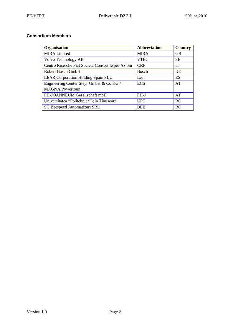
Consortium Members
Organisation Abbreviation Country
MIRA Limited MIRA GB
Volvo Technology AB VTEC SE
Centro Ricerche Fiat Società Consortile per Azioni CRF IT
Robert Bosch GmbH Bosch DE
LEAR Corporation Holding Spain SLU Lear ES
Engineering Center Steyr GmbH & Co KG /
MAGNA Powertrain
ECS AT
FH-JOANNEUM Gesellschaft mbH FH-J AT
Universitatea “Politehnica” din Timisoara UPT RO
SC Beespeed Automatizari SRL BEE RO
EE-VERT Deliverable D2.3.1 30June 2010
Document history
Version Description Planned
date
Actual
date
Editorial review by MIRA 30/06/2010 30/06/2010
1.0 First version of deliverable 30/06/2010 30/06/2010
A brief summary
Despite improvements in modern vehicles, a considerable amount of energy is still wasted due to the lack
of an overall on-board energy management strategy. Further electrification of auxiliary systems promises
energy and efficiency gains but there is an additional need for a coordinated approach to the generation,
distribution and use of energy.
The project “EE-VERT” is concerned with improving the energy efficiency of conventional vehicles.
The central concept is the electrification of auxiliary systems, and supplying their energy by recovered
energy from new sources or wasted energy such as recuperation of braking energy, waste heat recovery
or solar cells. In this context the storage device plays a key role for the system.
The objectives of work task 2.3 are to investigate possible storage technologies for the EE-VERT
approach, to select one or more adequate storage devices and to integrate them in the overall energy
management approach. To this end, the integration in the overall system approach will be studied via
simulations and with storage prototypes for test bench and demo car activities.
The present deliverable D2.3.1 reports on the storage concepts investigated, selected and developed by
EE-VERT that are needed for an advanced conventional vehicle with a very high level of efficiency.
This report will do the analysis from a theoretical point of view with studies and requirements
identification. Characteristics of the available storage technologies will be compared. Test bench
measurements will be used to validate the selected storage technology and will be reported in the
deliverable D2.3.2.
EE-VERT Deliverable D2.3.1 30June 2010
Version 1.0 Page 2
Contents
A BRIEF SUMMARY ..................................................................................................................... 1
GLOSSARY ..................................................................................................................................... 1
1 INTRODUCTION .................................................................................................................... 1
1.1 BACKGROUND .................................................................................................................... 1
1.2 PURPOSE............................................................................................................................. 1
1.3 SCOPE................................................................................................................................. 1
2 IMPACT OF EE-VERT ON THE STORAGE ....................................................................... 3
2.1 IMPACT OF THE EE-VERT APPROACH ................................................................................. 3
2.2 STORAGE REQUIREMENTS ................................................................................................... 4
3 STORAGE TECHNOLOGIES ............................................................................................... 6
3.1 LI-ION ................................................................................................................................ 6
3.1.1 Lithium-ion chemistries .................................................................................................. 6
3.1.2 EE-VERT High Voltage battery....................................................................................... 7
3.1.3 Development Programmes .............................................................................................. 7
3.1.4 Battery developments ...................................................................................................... 8
3.1.5 Notable automotive contracts for Lithium ion batteries ................................................... 9
3.2 ULTRACAPACITORS .......................................................................................................... 10
3.2.1 Ultracapacitor characteristics ...................................................................................... 10
3.2.2 Important characteristics for EE-VERT ........................................................................ 12
3.3 LEAD-ACID ....................................................................................................................... 14
3.3.1 Lead-acid chemistries ................................................................................................... 14
3.3.2 Important characteristics for EE-VERT ........................................................................ 14
3.4 NICKEL-BASED BATTERIES, SPECIFICALLY NIMH ............................................................. 16
3.4.1 Nickel-based battery chemistries ................................................................................... 16
3.4.2 Important characteristics for EE-VERT ........................................................................ 17
4 SUMMARY AND CONCLUSIONS ...................................................................................... 18
4.1 SUMMARY OF STORAGE CHARACTERISTICS ....................................................................... 18
4.2 SELECTION OF AN ADEQUATE STORAGE DEVICE ................................................................ 19
4.2.1 Battery or Ultracapacitor ............................................................................................. 19
4.2.2 Comparison of storage characteristics .......................................................................... 20
4.3 LI-ION BATTERY SPECIFICATION FOR EE-VERT ................................................................ 21
4.4 VALIDATION OF THE SELECTED STORAGE TECHNOLOGY ................................................... 22
4.4.1 Motivation .................................................................................................................... 22
4.4.2 A brief summary of the D2.3.2 results ........................................................................... 22
5 OUTLOOK ............................................................................................................................ 23
REFERENCES .............................................................................................................................. 24
EE-VERT Deliverable D2.3.1 30June 2010
Glossary
A Ampere
AC Air Conditioning
AGM Absorptive Glass Mat
Ah Ampere hour
C Capacity
D Deliverable
DC Direct Current
DLC Double-Layer Capacitor
DoE Department of Energy
E Energy
e.g. 'exempli gratia' - for example
ECU Electronic Control Unit
EDLC Electric Double-Layer Capacitor
EV Electric Vehicle
F Farad
FEV Fuel Economy Vehicle
G Generator
HEV Hybrid Electric Vehicle
HRPSOC High-rate partial SOC State-Of-Charge
ICE Internal Combustion Engine
kW Kilo Watts
Li Lithium
LiCoO2 Lithium Cobalt Oxide
Li-Ion Lithium Ion
MIPEC Multiple-Input Power Electronic
Converter
NiCD Nickel-Cadmium
NiMH Nickel-Metal Hydride
NEDC New European Driving Cycle
OEM Original Equipment Manufacturer
PHEV Plug-in Hybrid Electric Vehilce
R&D Research and Development
s second
S Starter
SB Samsung Bosch
SOC State Of Charge
US United Stated
USABC US Automotive Battery Conference
V Volt
VRLA Valve-Regulated Lead-Acid
W Watt
Wh Watt hour
WT Work Task
WP Work Package
rpm rounds per minute
EE-VERT Deliverable D2.3.1 30June 2010
1 Introduction
1.1 Background
The electrical system in conventional vehicles consists of a single electrical power bus, a generator
mechanically linked to the engine, an energy storage device (usually a 12V lead acid battery) and many
different loads. In present-day vehicles, even in those regarded as state-of-the-art, electrical power is
generated with little knowledge of the actual loads. In general, the energy required for auxiliary systems
(e.g. power steering, water pump, oil pump) is generated and consumed continuously, regardless of
demand. Similarly, the energy generation for the vehicle’s electrical system operates continuously.
Despite improvements in modern vehicles, a considerable amount of energy is still wasted due to the lack
of an overall on-board energy management strategy. Further electrification of auxiliary systems promises
energy and efficiency gains but there is an additional need for a coordinated approach to the generation,
distribution, use and storage of energy. In this context the storage device plays a key role for the system.
It is not the objective of EE-VERT to carry out technology research into specific storage techniques such
as Li-Ion batteries, ultra-capacitors, etc. as these are adequately covered in other research projects but to
develop behavioural models and identify constraints (temperature ranges, cycling properties) of the
devices to permit their integration into the system strategy of WP3.
The objectives of this work task are to investigate possible storage technologies for an overall energy
management strategy, to select one or more adequate storage devices and to integrate them in the overall
energy management approach. These activities will include the requirements engineering of the
necessary power electronics for the integration of the storage devices. To this end the integration in the
overall system approach will be studied via simulations and with storage prototypes for test bench and
demo car activities. Selected new storage devices will be integrated in the EE-VERT demonstrator car.
1.2 Purpose
This report presents and describes the investigation, selection and development of adequate storage
solutions for the EE-VERT approach.
1.3 Scope
The central EE-VERT concept is the electrification of auxiliary systems, and supplying their energy by a
high efficient electrical power generation. The EE-VERT concept considers the combination of several
different approaches to energy saving within an overall energy management strategy (thermal and
electrical). The approaches include:
Greater efficiency in energy generation with a new concept for the electrical generator and an
optimised overall operation strategy;
Energy recovery from wasted energy such as waste heat recovery or an optimised braking energy
recuperation with a temporarily increased generator output power with up to 6-10kW at a higher
voltage level; especially in this context the storage device plays a key role for the system;
EE-VERT Deliverable D2.3.1 30June 2010
Version 1.0 Page 2
Energy scavenging from unused and new energy sources, for example the use of solar cells; in
this context the storage device plays a key role for the system as well;
Greater efficiency in energy use by electrification of auxiliary systems with a very high
efficiency and an optimised overall operation strategy.
The present deliverable D2.3.1 reports on the storage concepts investigated, selected and developed by
EE-VERT needed for an advanced conventional vehicle with a very high level of efficiency.
EE-VERT Deliverable D2.3.1 30June 2010
Version 1.0 Page 3
2 Impact of EE-VERT on the storage
2.1 Impact of the EE-VERT approach
As proposed in §1.1 of D1.3.1 [3] the EE-VERT concept for power generation is based on two main
assumptions:
Possibility of using multiple power sources: To improve the overall efficiency of the vehicle,
new and improved generation sources are introduced. In all cars, generator with braking
recuperation capabilities will be incorporated. Also, other sources may be (optionally) introduced
including waste heat recovery and solar cells. The characteristics of these sources are highly
variable: some of them may be available at any time, but with varying efficiency depending on
operating conditions, others are only available under certain conditions. Therefore EE-VERT has
a special focus in combining different energy sources with the best interaction of their efficiency
characteristics.
Generation is decoupled from the conventional power net for consumers. Instead, an energy
converter device is introduced. This energy converter device is a multiple-input power electronics
converter (MIPEC). In this way, each generation device can be used in an efficient manner because
each source may be conditioned for an optimized power output. Also, the MIPEC is the enabler to
implement management strategies for saving energy during the vehicle operation by avoiding
current consumption by systems that are not in active use at the time.
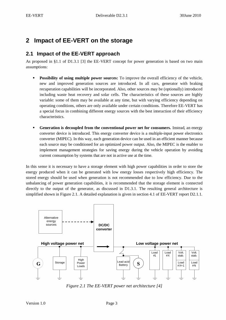
In this sense it is necessary to have a storage element with high power capabilities in order to store the
energy produced when it can be generated with low energy losses respectively high efficiency. The
stored energy should be used when generation is not recommended due to low efficiency. Due to the
unbalancing of power generation capabilities, it is recommended that the storage element is connected
directly to the output of the generator, as discussed in D1.3.1. The resulting general architecture is
simplified shown in Figure 2.1. A detailed explanation is given in section 4.1 of EE-VERT report D2.1.1.
Storage
Alternative energy sources
Load # 1
Volt . stab .
Load # X + 1
Load # X
Volt . stab .
Load # N S
Lead acid Battery
High Power Loads G
Low voltage power net
DC/DC
converter
High voltage power net
Figure 2.1 The EE-VERT power net architecture [4]
EE-VERT Deliverable D2.3.1 30June 2010
Version 1.0 Page 4
The general EE-VERT optimization approach can be summarized with the following main characteristics
which play an important role for the impact on the storage device.
High recuperation potential with up to 8kW by an increased generator power during braking
phase;
Energy recovery from additional sources, e.g. waste heat and solar cells, while normal operation
and also during parking (solar cells);
Drag torque reduced ICE through electrified auxiliaries (and downsizing);
Electrified auxiliaries are operated demand oriented with high efficiency, e.g. the electrical
vacuum pump;
Operation of electrified auxiliaries during stop-phase in start-stop vehicles to increase the
driver’s convenience, e.g. the AC compressor;
Architecture: Power net with a 2nd voltage level <60V due to a good cost-benefit ratio;
Main components: New generator concept, an adequate storage device and a DC/DC converter
for integration of multiple generation, actuation and storage devices.
The main impacts of the EE-VERT approach and the EE-VERT architecture on the storage device are
summarised in the following section as the storage requirements.
2.2 Storage requirements
This subchapter summarises the requirements identified for the storage devices. They have been derived
from the EE-VERT analysis especially in WP2 (D2.1.1 and D2.1.2) and WP3 (D3.1.1). These
requirements are necessary to develop adequate power generation solutions.
The introduction of additional electrification measures and functionalities within the EE-VERT approach
will represent a challenge for the storage device in terms of functionality, weight, vehicle integration,
safety, costs and lifetime. The following basic requirements are based on the architecture in Figure 2.1.
Key constraints on the storage device include:
Charging power: The storage device must have the ability to permit the charging with the
estimated maximum recuperation power of up to 8 or 10kW at least for a short time of several
seconds (<10s - duration of a braking phase). Beside high power charging the storage device
must also be able to be charged with low power during parking with good efficiency (e.g.
charging from the solar cells).
Voltage level: The voltage level in the “power” bus and therefore also for the storage device
must be within “safe” limits for human working. The low voltage directive specifies < 60V DC
[9]. A voltage level below 60V avoids additional safety means for personal safety.
Power net integration: The storage device will be directly coupled to the generator and must be
able to be charged with the generator.
Energy capability: The storage device must have a sufficient energy capability to allow the
supply of electrified auxiliaries during stop-phase.
EE-VERT Deliverable D2.3.1 30June 2010
Version 1.0 Page 5
Lifetime: The storage device must offer a high cycling and high calendar lifetime. The new
storage device must have a lifetime which is comparable to the typical calendar lifetime of a
state-of-the-art lead acid battery with considering the cost-benefit ratio. The higher the storage
costs the higher must be the lifetime to amortise the higher costs with the fuel saving benefits.
But as a basic requirement the EE-VERT storage device must offer a time of usage of at least 5
years to avoid customer’s dissatisfaction.
Operation: The storage device must have the flexibility to be used in a wide SOC range without
a dramatically decrease of lifetime or functionality. Furthermore it must have the flexibility to be
used whenever the system is able to deliver electrical energy with a high efficiency.
Technology: The storage must be based on a on the market available and safe storage
technology.
Discharging: Beside high power discharging for the electrified auxiliaries the storage must also
be able to be discharged with low power during parking with good efficiency.
Vehicle integration: The storage device must acceptably fulfil the space and weight
requirements.
EE-VERT Deliverable D2.3.1 30June 2010
Version 1.0 Page 6
3 Storage technologies
Storages used in automotive applications are all rechargeable (secondary batteries or possibly
ultracapacitors in the future)". Presently, more than ten different storage technologies have been
proposed. The most common are:
lithium-ion batteries,
nickel-based batteries including nickel-cadmium (NiCd) and nickel-metal hydride (NiMH),
lead–acid batteries, and
ultracapacitors.
In the following subchapters these different technologies will be discussed and analysed from an EE-
VERT point of view.
3.1 Li-ion
3.1.1 Lithium-ion chemistries
The main components of a lithium-ion battery are the anode, cathode, and electrolyte. The standard
anode of a conventional lithium-ion cell is made from carbon or graphite, the cathode is a metal oxide,
and the electrolyte is a lithium salt in an organic solvent. The voltage, capacity, life, and safety of a
lithium-ion battery are dependent on the choice of materials.
Typical Lithium-ion batteries used in laptops have Lithium Cobalt Oxide (LiCoO2) cathodes and a
graphite anode. These are typically formed as two sheets, kept apart by a plastic separator. The electrodes
are held within a liquid electrolyte. Unfortunately the release of oxygen when the cell is punctured or
overcharged can cause a fire or explosion. The safety circuit of the cobalt-based battery is typically
limited to a charge and discharge rate of about 1C. Another drawback is the increase of the internal
resistance that occurs with cycling and aging. After 2-3 years of use, the pack often becomes
unserviceable due to a large voltage drop under load that is caused by high internal resistance. The main
disadvantage of cobalt-based lithium-ion is the unfortunate release of oxygen when the cell is punctured
or overcharged that can cause a fire or explosion.
Lithium manganese oxide is a later development for the cathode material. It forms a three-dimensional
spinel structure that improves the ion flow between the electrodes. High ion flow lowers the internal
resistance and increases loading capability. The resistance stays low with cycling, though the battery
does age and the overall service life is similar to that of cobalt. Spinel has an inherently high thermal
stability and needs less safety circuitry than a cobalt system. A spinel-based lithium-ion cell can be
discharged at much higher rates of around 10C with marginal heat build-up.
A major advantage of Lithium iron phosphate materials is that they are more stable and do not support
combustion. Titanate anodes are being investigated, particularly in combination with Lithium manganese
oxide cathodes [8]. At this time the lithium iron phosphate chemistry is available from several suppliers
and with its inherent safety in terms of passive reaction to physical damage makes it the first choice for
automotive applications.
EE-VERT Deliverable D2.3.1 30June 2010
Version 1.0 Page 7
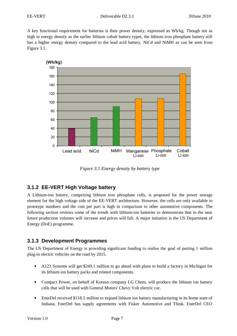
A key functional requirement for batteries is their power density, expressed as Wh/kg. Though not as
high in energy density as the earlier lithium cobalt battery types, the lithium iron phosphate battery still
has a higher energy density compared to the lead acid battery, NiCd and NiMH as can be seen from
Figure 3.1.
Figure 3.1 Energy density by battery type
3.1.2 EE-VERT High Voltage battery
A Lithium-ion battery, comprising lithium iron phosphate cells, is proposed for the power storage
element for the high voltage side of the EE-VERT architecture. However, the cells are only available in
prototype numbers and the cost per part is high in comparison to other automotive components. The
following section reviews some of the trends with lithium-ion batteries to demonstrate that in the near
future production volumes will increase and prices will fall. A major initiative is the US Department of
Energy (DoE) programme.
3.1.3 Development Programmes
The US Department of Energy is providing significant funding to realise the goal of putting 1 million
plug-in electric vehicles on the road by 2015.
A123 Systems will get $249.1 million to go ahead with plans to build a factory in Michigan for
its lithium ion battery packs and related components.
Compact Power, on behalf of Korean company LG Chem, will produce the lithium ion battery
cells that will be used with General Motors' Chevy Volt electric car.
EnerDel received $118.5 million to expand lithium ion battery manufacturing in its home state of
Indiana. EnerDel has supply agreements with Fisker Automotive and Think. EnerDel CEO
EE-VERT Deliverable D2.3.1 30June 2010
Version 1.0 Page 8
Charles Gassenheimer said that the grant will allow the company to double the volume at its
existing auto battery plant in Indiana and forecast that costs could fall as much as 40% by 2015.
Saft America will receive $95.5 million to produce lithium ion cells and batteries for industrial,
agricultural, and defense vehicles.
3.1.4 Battery developments
US DoE Research programme
Under the US DoE Energy Storage and Research programme the Battery Development is organized into
benchmark testing and full system development. More details can be found in [10].
Benchmark Testing – The benchmark testing of emerging technologies is needed to remain abreast of the
latest industry developments. Working with the national laboratories, DOE’s Vehicle Technologies
Program office purchases vehicles and independently tests hardware against manufacturers’
specifications and the most applicable technical targets.
Full System Development – In cooperation with industry, efforts are focused on developing (and
evaluating) lithium batteries and ultracapacitor technologies for vehicles. Specifically, this work is
focused on developing batteries for HEV and PHEV applications and ultracapacitor technologies for
start/stop applications.
Applied Battery Research is focused on addressing the cross-cutting barriers that face Li-ion systems
which are closest to meeting all energy and power requirements for use in vehicles. Several national
laboratories participate in this activity, each bringing its own expertise to address the barriers: life, abuse
tolerance, low-temperature performance, and cost.
Focused Fundamental Battery Research addresses fundamental problems of chemical instabilities that
impede the development of advanced batteries, investigates new and promising materials, provides a
better understanding of why systems fail, and develops models to predict system failure and enable
system optimization. National laboratories, universities, and some commercial entities participate in this
activity.
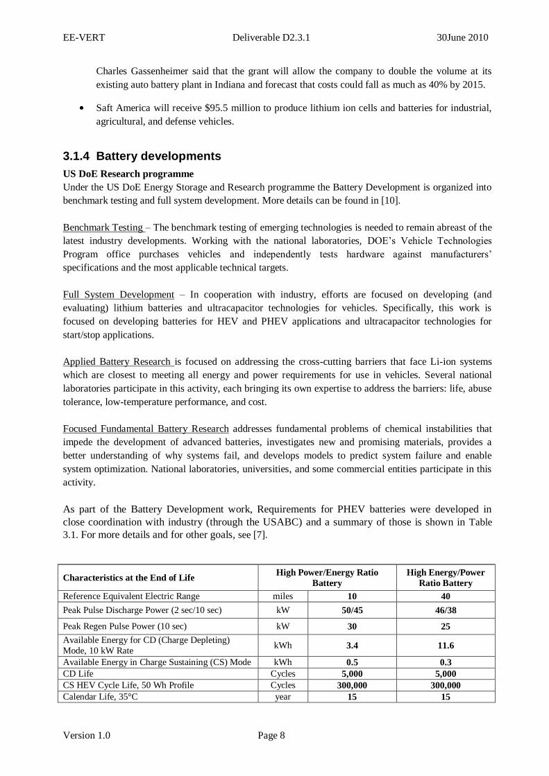
As part of the Battery Development work, Requirements for PHEV batteries were developed in
close coordination with industry (through the USABC) and a summary of those is shown in Table
3.1. For more details and for other goals, see [7].
Characteristics at the End of Life High Power/Energy Ratio
Battery
High Energy/Power
Ratio Battery
Reference Equivalent Electric Range miles 10 40
Peak Pulse Discharge Power (2 sec/10 sec) kW 50/45 46/38
Peak Regen Pulse Power (10 sec) kW 30 25
Available Energy for CD (Charge Depleting)
Mode, 10 kW Rate kWh 3.4 11.6
Available Energy in Charge Sustaining (CS) Mode kWh 0.5 0.3
CD Life Cycles 5,000 5,000
CS HEV Cycle Life, 50 Wh Profile Cycles 300,000 300,000
Calendar Life, 35°C year 15 15
EE-VERT Deliverable D2.3.1 30June 2010
Version 1.0 Page 9
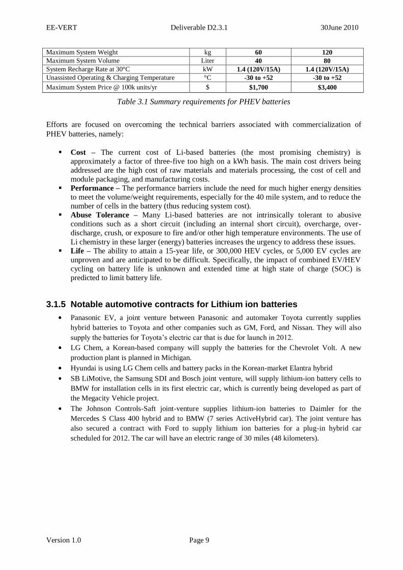
Maximum System Weight kg 60 120
Maximum System Volume Liter 40 80
System Recharge Rate at 30°C kW 1.4 (120V/15A) 1.4 (120V/15A)
Unassisted Operating & Charging Temperature °C -30 to +52 -30 to +52
Maximum System Price @ 100k units/yr $ $1,700 $3,400
Table 3.1 Summary requirements for PHEV batteries
Efforts are focused on overcoming the technical barriers associated with commercialization of
PHEV batteries, namely:
Cost – The current cost of Li-based batteries (the most promising chemistry) is
approximately a factor of three-five too high on a kWh basis. The main cost drivers being
addressed are the high cost of raw materials and materials processing, the cost of cell and
module packaging, and manufacturing costs.
Performance – The performance barriers include the need for much higher energy densities
to meet the volume/weight requirements, especially for the 40 mile system, and to reduce the
number of cells in the battery (thus reducing system cost).
Abuse Tolerance – Many Li-based batteries are not intrinsically tolerant to abusive
conditions such as a short circuit (including an internal short circuit), overcharge, over-
discharge, crush, or exposure to fire and/or other high temperature environments. The use of
Li chemistry in these larger (energy) batteries increases the urgency to address these issues.
Life – The ability to attain a 15-year life, or 300,000 HEV cycles, or 5,000 EV cycles are
unproven and are anticipated to be difficult. Specifically, the impact of combined EV/HEV
cycling on battery life is unknown and extended time at high state of charge (SOC) is
predicted to limit battery life.
3.1.5 Notable automotive contracts for Lithium ion batteries
Panasonic EV, a joint venture between Panasonic and automaker Toyota currently supplies
hybrid batteries to Toyota and other companies such as GM, Ford, and Nissan. They will also
supply the batteries for Toyota’s electric car that is due for launch in 2012.
LG Chem, a Korean-based company will supply the batteries for the Chevrolet Volt. A new
production plant is planned in Michigan.
Hyundai is using LG Chem cells and battery packs in the Korean-market Elantra hybrid
SB LiMotive, the Samsung SDI and Bosch joint venture, will supply lithium-ion battery cells to
BMW for installation cells in its first electric car, which is currently being developed as part of
the Megacity Vehicle project.
The Johnson Controls-Saft joint-venture supplies lithium-ion batteries to Daimler for the
Mercedes S Class 400 hybrid and to BMW (7 series ActiveHybrid car). The joint venture has
also secured a contract with Ford to supply lithium ion batteries for a plug-in hybrid car
scheduled for 2012. The car will have an electric range of 30 miles (48 kilometers).
EE-VERT Deliverable D2.3.1 30June 2010
Version 1.0 Page 10
3.2 Ultracapacitors
3.2.1 Ultracapacitor characteristics
Ultracapacitors (also called supercapacitors) are very high surface area capacitors that use as dielectric a
molecule-thin layer of electrolyte to separate charge. Energy is stored in the electrostatic field (and
therefore highly reversible) rather than as a chemical state as in batteries. Ultracapacitors rely on an
electrostatic effect. The dielectric medium between the electrodes is a solution containing ions from a salt
that is added to an appropriate solvent. The operating voltage is controlled by the breakdown voltages of
the solvents with aqueous electrolytes (1.1V) and organic electrolytes (2.5V to 3V).
This energy storage process is in contrast to all battery technologies, which are based on chemical
reactions. With no chemical bonds being made or broken, cycle life of over 500,000 cycles at 100%
depth of discharge has been demonstrated with minimal degradation. The limiting factor in terms of
lifetime may be the years of operation with reported lifetimes reaching up to 12 years. Another limiting
factor is the high self-discharge rate of ultracapacitors. This rate is much higher than batteries reaching a
level of 14% of nominal energy per month.
Capacitances of 5,000F have been reported with ultracapacitors and energy densities up to 5Wh/kg
compared to 0.5Wh/kg of conventional capacitors. Energy efficiency is normally above 90% if they are
kept within their design limits. Furthermore, unlike batteries, almost all of this energy is available in a
reversible process. This means that ultracapacitors are able to deliver or accept high currents, but only for
shorter periods than batteries.
Therefore, their energy density is lower than that of batteries while their power density is higher,
reaching values such as 10,000 W/kg which is a few orders of magnitude higher than the power densities
achieved with batteries.
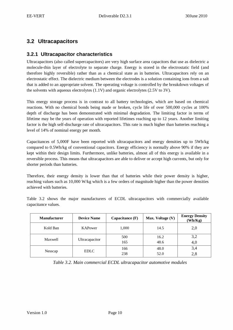
Table 3.2 shows the major manufacturers of ECDL ultracapacitors with commercially available
capacitance values.
Manufacturer Device Name Capacitance (F) Max. Voltage (V) Energy Density
(Wh/Kg)
Kold Ban KAPower 1,000 14.5 2,0
Maxwell Ultracapacitor 500
165
16.2
48.6
3,2
4,0
Nesscap EDLC 166
238
48.0
52.0
3,4
2,8
Table 3.2. Main commercial ECDL ultracapacitor automotive modules
EE-VERT Deliverable D2.3.1 30June 2010
Version 1.0 Page 11
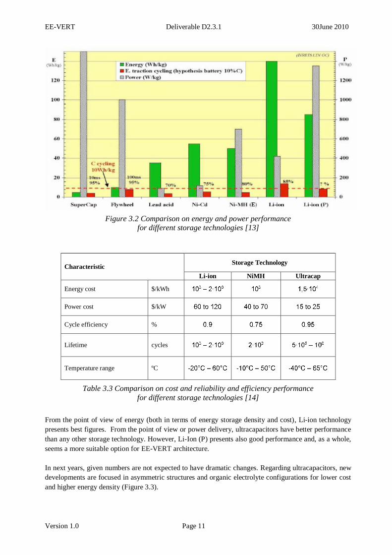
Figure 3.2 Comparison on energy and power performance
for different storage technologies [13]
Characteristic Storage Technology
Li-ion NiMH Ultracap
Energy cost $/kWh
Power cost $/kW
Cycle efficiency %
Lifetime cycles
Temperature range ºC
Table 3.3 Comparison on cost and reliability and efficiency performance
for different storage technologies [14]
From the point of view of energy (both in terms of energy storage density and cost), Li-ion technology
presents best figures. From the point of view or power delivery, ultracapacitors have better performance
than any other storage technology. However, Li-Ion (P) presents also good performance and, as a whole,
seems a more suitable option for EE-VERT architecture.
In next years, given numbers are not expected to have dramatic changes. Regarding ultracapacitors, new
developments are focused in asymmetric structures and organic electrolyte configurations for lower cost
and higher energy density (Figure 3.3).
EE-VERT Deliverable D2.3.1 30June 2010
Version 1.0 Page 12
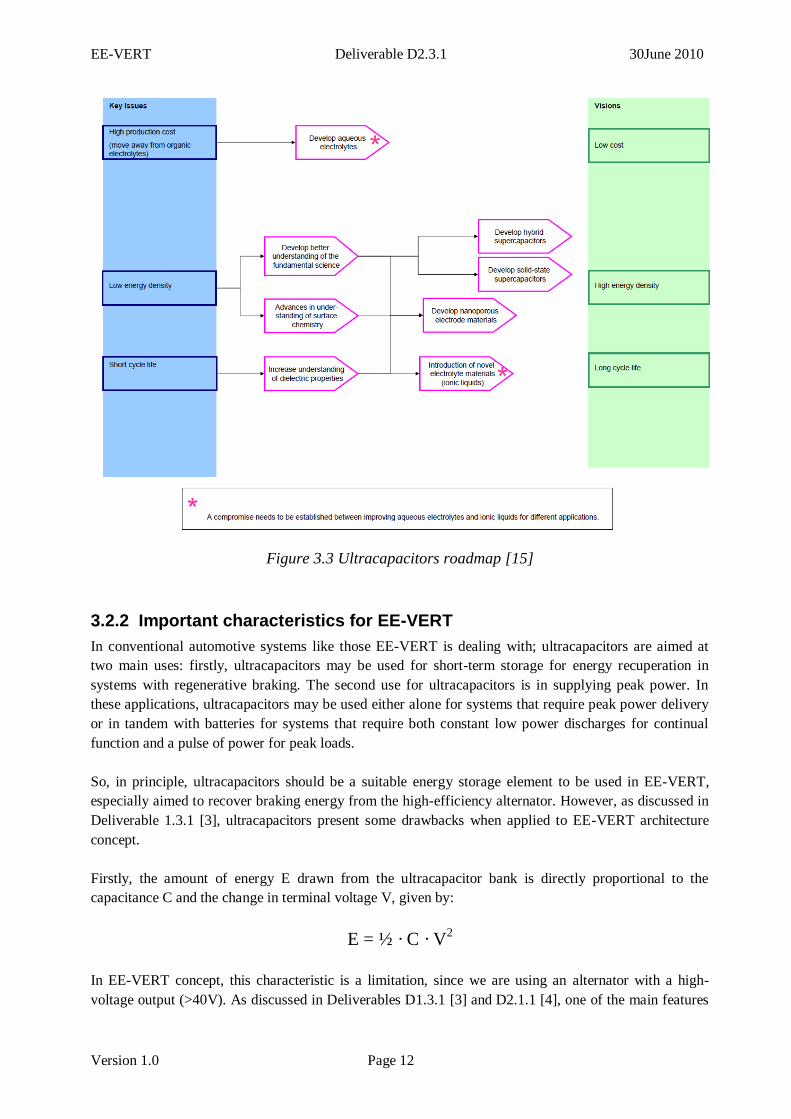
Figure 3.3 Ultracapacitors roadmap [15]
3.2.2 Important characteristics for EE-VERT
In conventional automotive systems like those EE-VERT is dealing with; ultracapacitors are aimed at
two main uses: firstly, ultracapacitors may be used for short-term storage for energy recuperation in
systems with regenerative braking. The second use for ultracapacitors is in supplying peak power. In
these applications, ultracapacitors may be used either alone for systems that require peak power delivery
or in tandem with batteries for systems that require both constant low power discharges for continual
function and a pulse of power for peak loads.
So, in principle, ultracapacitors should be a suitable energy storage element to be used in EE-VERT,
especially aimed to recover braking energy from the high-efficiency alternator. However, as discussed in
Deliverable 1.3.1 [3], ultracapacitors present some drawbacks when applied to EE-VERT architecture
concept.
Firstly, the amount of energy E drawn from the ultracapacitor bank is directly proportional to the
capacitance C and the change in terminal voltage V, given by:
E = ½ · C · V2
In EE-VERT concept, this characteristic is a limitation, since we are using an alternator with a high-
voltage output (>40V). As discussed in Deliverables D1.3.1 [3] and D2.1.1 [4], one of the main features
EE-VERT Deliverable D2.3.1 30June 2010
Version 1.0 Page 13
of EE-VERT architecture is the use of a new high efficiency alternator working at high voltage. This
alternator can recuperate a very high amount of energy during braking provided that the voltage is over
40V.
When using an ultracapacitor, the system will (usually) start the process of charging the ultracapacitor
(for instance, when braking) from a low-level voltage and it will increase the voltage during the charging
process. To do this, the alternator output is connected to the ultracapacitor. In this situation, the power
from the generator will be limited due to the low voltage. Therefore, recuperation capability of the
system is really not used / wasted.
At final phases of recuperation, when the ultracapacitor is already charged and works on a higher voltage
level, the kinetic energy of the car is lower and restricted. In this case, the ultracapacitor limits again the
amount of energy to be recuperated. This is of course "fixed" with a high capacitance but this will cost in
money and weight.
Using a high-efficiency battery instead of an ultracapacitor, the energy storage system may sustain,
during the whole braking phase, a high voltage level and get therefore more power out of the generator.
Hence, a battery on the higher voltage level is presumably the better choice, as introduced in Deliverable
1.3.1 [3] and discussed in Deliverable D2.1.1 [4].
Furthermore, the charging and discharging of the ultracapacitor poses some practical problems. Although
it is possible to directly connect the ultracapacitor and the generator, and have the charge of the
ultracapacitor controlled / limited by the alternator, it is not recommendable due to the safety reasons.
The huge amount of energy stored in the ultracapacitor may be dangerous if the terminals of the
ultracapacitor are electrically accessible. Secondly, voltage range in HV power net is broader (could be
less that 14V) and, therefore, the DC/DC converter needed to convert to the 14V power net is more
complex than in the other case, since it needs to be a buck-boost type.
An alternative solution is the use of specific power-electronics to control the charge and discharge of the
ultracapacitor. In this case, a bidirectional buck-boost is also required (it may be integrated in the
MIPEC). However, this solution also presents a major drawback: the power electronics needed to support
the high power current bursts (6-8KW) requires a very expensive solid-state relay circuitry.
Furthermore, the energy harvesting from other sources such as solar cell or thermal waste recovery may
be fully utilised when using a battery. In this way, it is more probable that the car starts its journey with
almost full batteries, which gives much more flexibility for energy management at system level. Using an
ultracapacitor instead of a high-voltage battery, the SOC of the ultracapacitor may not be high in all
cases.
In conclusion, to the characteristics of power generation elements to be used in EE-VERT and the
characteristics of Li-Ion (P) batteries and ultracapacitors, we currently believe ultracapacitors would limit
the amount of energy the system can recuperate in EE-VERT compared to when using Li-Ion (P)
batteries.
EE-VERT Deliverable D2.3.1 30June 2010
Version 1.0 Page 14
3.3 Lead-acid
3.3.1 Lead-acid chemistries
Lead–acid (wet) batteries
Lead–acid (wet) batteries are the oldest type of rechargeable batteries and are based on chemical
reactions involving lead dioxide which forms the cathode electrode, lead which forms the anode
electrode and sulphuric acid which acts as the electrolyte.
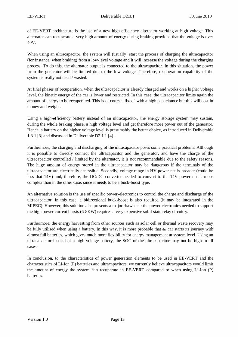
Figure 3.4 Internal structure of an AGM lead-acid battery
AGM batteries
AGM batteries eliminate fluid electrolyte by absorbing and retaining the sulphuric acid electrolyte with
mat separators made of glass fibre unwoven cloth. Therefore, these batteries are named AGM, from
absorptive glass mat. Batteries can be closed because oxygen evolved from water decomposition during
charging is reduced to water on negative plate surfaces. Battery elements are closed by a safety valve that
keeps internal pressure below a certain level by releasing pressure when it rises, which is the reason for
calling them “valve-regulated lead-acid batteries” (VRLA). Features of VRLA batteries are that, unlike
flooded batteries, they have a very low water loss, and that there are few limitations on their installation
orientation. Valve-regulated lead–acid (VRLA) batteries can withstand higher Ah turnover than the
classical wet lead-acid battery. Figure 3.4 shows the internal structure of a lead-acid battery (AGM).
3.3.2 Important characteristics for EE-VERT
The rated voltage of a lead–acid cell is 2V and the typical energy density is around 30Wh/kg with the
power density around 180W/kg. Lead–acid batteries have high energy efficiencies (between 85% and
90%), are easy to install and require relatively low levels of both maintenance and investment cost. In
addition, the self-discharge rates for this type of batteries are very low, around 2% of rated capacity per
month (at 25 ºC) which makes them ideal for long-term storage applications.
The limiting factors for these batteries are the comparatively low life cycle and the battery operational
lifetime. Typical lifetimes of lead–acid batteries are between 600 and 800 charge/discharge cycles or 4–7
EE-VERT Deliverable D2.3.1 30June 2010
Version 1.0 Page 15
years of operation. The life cycle is affected by the depth of discharge and temperature. Is the depth of
discharge lower than 80% SOC the battery ageing is dramatically increased. Attempts to fully discharge
the battery can be particularly damaging to the electrodes, thus reducing lifetime. Regarding temperature
levels, although high temperatures (up to 55ºC which is the upper limit for battery operation) may
improve the battery performance in terms of higher capacity, they can also reduce total battery lifetime as
well as the battery energy efficiency.
AGM batteries give at least a threefold increase of the life cycle compared to wet lead-acid, at an equal
or even higher power density. Further improvements can be expected from ongoing R&D work
optimizing AGM technology for high-rate partial state-of-charge (HRPSOC) operation. This technology
development has been originally devoted to 42V mild-hybrid vehicles, but it is also applied to 12V
systems, e.g. for engine stop/start applications and regenerative braking.
Since AGM batteries are becoming very popular for use in stop & start applications, their price is falling,
with a potential of long term and high volume part cost reaching 1.2–1.3 times that of a wet type. AGM
batteries have a good potential to become the de facto standard for automotive applications where
medium to high life cycle is required since the cost per charge throughput during battery life outperforms
the wet battery technology.
Actual usage of batteries
Today’s vehicle electric power systems, with the battery as an essential component, are characterized by
the increasing number and associated power demand of electrical consumers, by packaging issues, and
by the limitation of the operational voltage of electronic components.
Power net stability
In modern vehicles, electronic ICE controllers allow reduced idling rpm to lower the emissions, while
many comfort components and devices which are electrically driven require a lot of power. Under poor
weather conditions in a hot climate, with air conditioning, headlights and wipers on and the electrical
cooling fan of the ICE in operation periodically, the alternator cannot supply sufficient current. When the
vehicle is in idle, the alternator is capable of providing about 70A. The battery has to provide the
difference. If the electrical power assisted steering is activated, battery discharge peaks reach up to 120A
or even higher.
EE-VERT Deliverable D2.3.1 30June 2010
Version 1.0 Page 16
3.4 Nickel-based batteries, specifically NiMH
3.4.1 Nickel-based battery chemistries
NiMH is one of the three nickel-based batteries. The others are nickel–cadmium (NiCd) and the nickel–
zinc (NiZn) batteries. All three types use the same material for the positive electrode and the electrolyte
which is nickel hydroxide and an aqueous solution of potassium hydroxide with some lithium hydroxide,
respectively. As for the negative electrode, the NiCd type uses cadmium hydroxide, the NiMH uses a
metal alloy and the NiZn uses zinc hydroxide. The rated voltage for the alkaline batteries is 1.2V (1.65V
for the NiZn type) and energy densities ranging from around 50 to 120Wh/kg.
The nickel-metal hydride offers up to 40% higher energy density compared to the standard nickel-
cadmium. There is potential for yet higher capacities, but not without some negative side effects.
Nickel-metal hydride is less durable than nickel-cadmium. Cycling under heavy load and storage at high
temperature reduces the service life. Nickel-metal hydride suffers from high self-discharge.
Nickel-metal hydride has been replacing nickel-cadmium in markets such as wireless communications
and mobile computing. Nickel-metal hydride has greatly improved over the years, but limitations remain. Most shortcomings are native to the nickel-based technology and are shared with nickel-cadmium. It is
widely accepted that nickel-metal hydride is an interim step to lithium-based battery technology.
Advantages of NiMH
Capacity 30-40% higher than standard NiCd. NiMH has potential for yet higher energy densities.
Less prone to memory than NiCd - fewer exercise cycles are required.
Transportation is not subject to regulatory control.
Environmentally friendly, containing only mild toxins; profitable for recycling.
Limitations of NiMH
Limited service life - the performance starts to deteriorate after 200-300 cycles if repeatedly
deeply cycled.
Relatively short storage of three years. Cool temperature and a partial charge slow down aging.
Limited discharge current - although NiMH is capable of delivering high discharge currents,
heavy load reduces the battery's cycle life.
More complex charge algorithm needed - NiMH generates more heat during charge and requires slightly longer charge times than NiCd. Trickle charge settings are critical because the battery
cannot absorb overcharge.
High self-discharge - typically 50% higher than NiCd.
Performance degrades if the battery is stored at elevated temperatures - NiMH should be stored
in a cool place at 40% state-of-charge.
EE-VERT Deliverable D2.3.1 30June 2010
Version 1.0 Page 17
High maintenance - NiMH requires regular full discharge to prevent crystalline formation. NiCd
should be exercised once a month, NiMH once in every 3 months.
3.4.2 Important characteristics for EE-VERT
Typically, power density values are 50 Wh/kg for the NiCd, 80 Wh/kg for the NiMH and 60 Wh/kg for
the NiZn. Typical operational life and life cycle of NiCd batteries is also superior in comparison to the
lead–acid batteries. At deep discharge levels, typical lifetimes for the NiCd batteries range from 1,500
cycles for the pocket plate vented type to 3,000 cycles for the sinter vented type. The NiMH and NiZn
have similar or lower values to those of the lead–acid batteries.
Despite the above advantages of the NiCd batteries over the lead–acid batteries, NiCd and the rest of the
nickel-based batteries have several disadvantages compared to the lead–acid batteries for low voltage
systems. First the energy efficiencies for the nickel batteries are lower than for the lead–acid batteries.
The NiMH batteries have energy efficiencies between 65 and 70% while the NiZn have 80% efficiency.
The energy efficiency of the NiCd batteries varies depending on the type of technology used during
manufacture, ranging from 60% for the pocket plate vented type to 73% for the sinter plate. Self-
discharge rates for an advanced NiCd battery are much higher than those for a lead–acid battery, in some
cases reaching more than 10% of rated capacity per month. Finally, NiCd battery may cost up to 10 times
more than the lead–acid battery and cadmium is particularly toxic, limiting the possibility of increasing
the usage of NiCd.
Nickel-metal hydride (NiMH) batteries are currently dominating the automotive traction market.
Applications include battery electric vehicles like the Toyota RAV4-EV and GM EV1 and hybrid
electric vehicles such as the Toyota Prius or Honda Civic. However, concerns about the rising price of
nickel and an efficiency of around 70% support predictions that lithium-ion batteries are likely to become
the first choice for HEVs.
EE-VERT Deliverable D2.3.1 30June 2010
Version 1.0 Page 18
4 SUMMARY AND CONCLUSIONS
4.1 Summary of storage characteristics
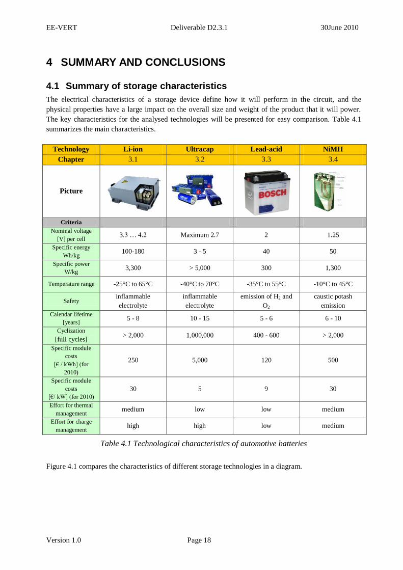
The electrical characteristics of a storage device define how it will perform in the circuit, and the
physical properties have a large impact on the overall size and weight of the product that it will power.
The key characteristics for the analysed technologies will be presented for easy comparison. Table 4.1
summarizes the main characteristics.
Technology Li-ion Ultracap Lead-acid NiMH
Chapter 3.1 3.2 3.3 3.4
Picture
Criteria
Nominal voltage
[V] per cell 3.3 … 4.2 Maximum 2.7 2 1.25
Specific energy
Wh/kg 100-180 3 - 5 40 50
Specific power
W/kg 3,300 > 5,000 300 1,300
Temperature range -25°C to 65°C -40°C to 70°C -35°C to 55°C -10°C to 45°C
Safety inflammable
electrolyte
inflammable
electrolyte
emission of H2 and
O2
caustic potash
emission
Calendar lifetime
[years] 5 - 8 10 - 15 5 - 6 6 - 10
Cyclization
[full cycles] > 2,000 1,000,000 400 - 600 > 2,000
Specific module
costs
[€ / kWh] (for
2010)
250 5,000 120 500
Specific module
costs
[€/ kW] (for 2010)
30 5 9 30
Effort for thermal
management medium low low medium
Effort for charge
management high high low medium
Table 4.1 Technological characteristics of automotive batteries
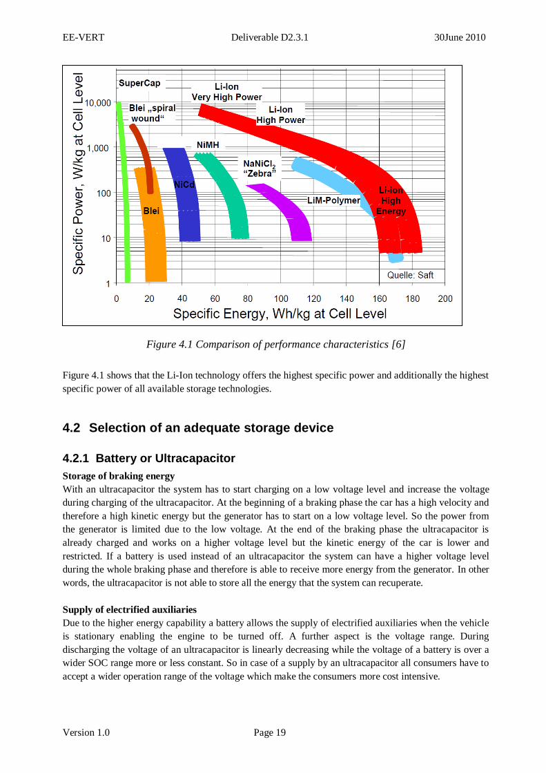
Figure 4.1 compares the characteristics of different storage technologies in a diagram.
EE-VERT Deliverable D2.3.1 30June 2010
Version 1.0 Page 19
Figure 4.1 Comparison of performance characteristics [6]
Figure 4.1 shows that the Li-Ion technology offers the highest specific power and additionally the highest
specific power of all available storage technologies.
4.2 Selection of an adequate storage device
4.2.1 Battery or Ultracapacitor
Storage of braking energy
With an ultracapacitor the system has to start charging on a low voltage level and increase the voltage
during charging of the ultracapacitor. At the beginning of a braking phase the car has a high velocity and
therefore a high kinetic energy but the generator has to start on a low voltage level. So the power from
the generator is limited due to the low voltage. At the end of the braking phase the ultracapacitor is
already charged and works on a higher voltage level but the kinetic energy of the car is lower and
restricted. If a battery is used instead of an ultracapacitor the system can have a higher voltage level
during the whole braking phase and therefore is able to receive more energy from the generator. In other
words, the ultracapacitor is not able to store all the energy that the system can recuperate.
Supply of electrified auxiliaries
Due to the higher energy capability a battery allows the supply of electrified auxiliaries when the vehicle
is stationary enabling the engine to be turned off. A further aspect is the voltage range. During
discharging the voltage of an ultracapacitor is linearly decreasing while the voltage of a battery is over a
wider SOC range more or less constant. So in case of a supply by an ultracapacitor all consumers have to
accept a wider operation range of the voltage which make the consumers more cost intensive.
Lead
EE-VERT Deliverable D2.3.1 30June 2010
Version 1.0 Page 20
From these important points it can be derived that a battery instead of an ultracapacitor on the higher
voltage level is the better choice. In the next section is justified which battery technology will be used by
EE-VERT.
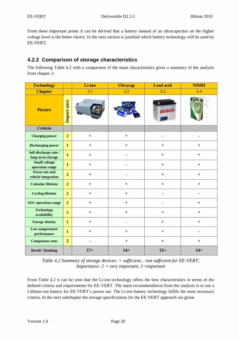
4.2.2 Comparison of storage characteristics
The following Table 4.2 with a comparison of the main characteristics gives a summary of the analysis
from chapter 3.
Technology Li-ion Ultracap Lead acid NIMH
Chapter 3.1 3.2 3.3 3.4
Picture
Imp
ort
an
ce
Criteria
Charging power 2 + + - -
Discharging power 1 + + + +
Self discharge rate /
long-term storage 1 + - + +
Small voltage
operation range 1 + - + +
Power net and
vehicle integration 2 + - + +
Calendar lifetime 2 + + + +
Cycling lifetime 2 + + - -
SOC operation range 2 + + - +
Technology
availability 2 + + + +
Energy density 1 + - + +
Low temperature
performance 1 + + + -
Component costs 2 - + + +
Result / Ranking 17+ 14+ 13+ 14+
Table 4.2 Summary of storage devices: + sufficient, - not sufficient for EE-VERT;
Importance: 2 = very important, 1=important
From Table 4.2 it can be seen that the Li-ion technology offers the best characteristics in terms of the
defined criteria and requirements for EE-VERT. The main recommendation from the analysis is to use a
Lithium-ion battery for EE-VERT’s power net. The Li-ion battery technology fulfils the most necessary
criteria. In the next subchapter the storage specifications for the EE-VERT approach are given.
EE-VERT Deliverable D2.3.1 30June 2010
Version 1.0 Page 21
4.3 Li-Ion battery specification for EE-VERT
The main recommendations from the analysis are to use a Li-ion battery operating at 40V DC (nominal)
with a capacity of 64Ah for the main solution. The main reasons are:
Most flexible solution: 40V 64Ah Li-Ion “power” battery; 40V is a good compromise between
power capability and safety (<60V);
Charge current capability: 64Ah are necessary with the currently available Li-Ion technology to
be able to charge with a current of 200A;
Permits electrified auxiliary operation during stop phase, for instance electrified air-conditioning;
Possible downsizing of 12V “energy” battery, if a voltage modified starter is connected to the
high voltage level and not the 14V power net;
Present-day mass, size and price of Li-Ion pack is an acknowledged issue, but this is expected to
improve due to the impetus of current of research programmes into battery technology.
Maximum recuperation power and voltage level
With an aimed recuperation power of maximum 8kW the storage device has to be able to tolerate a
charging current of up to 200A. The proposed 40V Li-Ion battery is based on the manufacturer LiFeBatt
8Ah lithium iron phosphate cells with 12 cells in series giving a nominal voltage of 39.6V (3.3V/cell)
and 8 cells in parallel to accept a maximum charge rate of 200A (25A/cell). This results in a maximum
charge power of 8.8kW and a 64Ah capacity. The maximum charging voltage is 3.65V/cell, giving a
maximum battery charging voltage of 43.8V. The battery includes cell balancing electronics that operate
during charging. Warning signals are available to the control system: High voltage 3.85V and low
voltage 2.4V as well as temperature warnings. The high and low warning signals can be used to provide
an outer loop control. When the high voltage signal is triggered the charging current should be limited to
1A by the system management and the generator regulator.
Lifetime of the battery
The “high” capacity leads to an acceptable lifetime for the battery. With charging and discharging
calculations it has been estimated that the lifetime of the battery in EE-VERT’s recuperation approach is
about 8.5 years for 15,000 kilometres travelled per year and 6.4 years for 20,000 kilometres travelled per
year respectively. Since the intended lifetime is at least 5 years the 40V DC 64Ah battery is sufficient
and offers an additional optimisation potential for downsizing the 12V battery.
Weight and required space
The physical size is approximately 600x400x210 mm and a weight of around 30kg. With CRF it has
been clarified that it is possible to integrate a battery with this dimensions into the demonstrator car.
Baseline solution
The main recommendation for EE-VERT is to use a Li-Ion battery due to the reasons above.
Nevertheless an ultracapacitor could be used in a baseline architecture solution, if only brake energy
recuperation is required. In this case it is not possible to store energy from different sources over a longer
period due to the low energy level of an ultracapacitor. Note that the 12V lead-acid battery which is still
in the system could not be used to store this energy because the operational strategy of this battery is to
keep the state of charge always near to 100%. With the low energy level it is also not possible to supply
electrified auxiliaries during stand-still phases. Hence, an ultracapacitor can only fulfil the requirements
for a baseline braking recuperation solution.
EE-VERT Deliverable D2.3.1 30June 2010
Version 1.0 Page 22
4.4 Validation of the selected storage technology
4.4.1 Motivation
This report has performed the analysis from a theoretical point of view with studies and requirements
identification. Characteristics of the available storage technologies have been compared. The validation
of the selected storage technology will be analysed and reported in the deliverable D2.3.2 [12].
The deliverable D2.3.2 reports about the validation of the selected Li-Ion storage technology with test
bench measurements. The motivation of the battery and cell testing in D2.3.2 is to figure out which
available cell type is suitable for the EE-VERT approach. There is a need to know if the data sheet values
are the same in comparison to the measured values of those battery cells. Another reason is the electric
behaviour of those cells and the resultant thermal behaviour of the cells especially at certain currents.
The charge and discharge acceptance of the cell is needed information which will be a result of the
battery cell testing. This is especially important for the recuperation approach of EE-VERT. All the tests
have been done with single cells and not with a full battery pack.
The tests have been done at a Bosch battery test bay. The test bay is a MACCOR battery tester which is
capable of several hundred amperes and volts. With this tester EE-VERT is able to test the cells to their
maximum specifications and beyond. All the testing procedures and boundaries are given in D2.3.2.
4.4.2 A brief summary of the D2.3.2 results
This section will give a brief summary of D2.3.2 to show the bridge to the validation of the selected
storage technology.
It is shown in D2.3.2 that the LiFeBatt cells are the most suitable battery cells to use in the demonstrator
car. One of the most important facts: the measured capacity is equivalent to the data sheet capacity. Also
the battery is capable of handling the full 4C charge rate without problems. The cells were able to
maintain the temperature during dynamic charging and discharging. Only with discharge currents higher
then 15C the cells reached the critical temperature of 45°C. The normal operation strategy of the
demonstrator won’t allow discharge currents greater then 4C.
Another result of those tests was the charge acceptance performance of the battery cells. It is important to
know if the battery is capable of storing all the energy during recuperation with high efficiency. The
charge acceptance performance was almost constant at different SOC levels.
Another reason to choose the LiFeBatt cells is the higher current rating per cell, which means fewer cells
are needed for the required maximum charge current of the battery pack. This also means a higher
capacity per volume and therefore a lower weight and a lower required integration space in the car.
It also turned out during that it is easier to assemble the LiFeBatt cells than the A123systems cells.
Therefore the concept design of the 40V lithium ion storage system developed in EE-VERT will be
based on LiFeBatt cells.
EE-VERT Deliverable D2.3.1 30June 2010
Version 1.0 Page 23
5 OUTLOOK
The project “EE-VERT” is concerned with improving the energy efficiency of conventional vehicles.
The central concept is the electrification of auxiliary systems, and supplying their energy by recovered
energy from new sources or wasted energy such as recuperation of braking energy, waste heat recovery
or solar cells. The storage device plays in this concept a key role. Only if the storage device is able to
fulfil its specified tasks over the whole expected lifetime the EE-VERT concept can succeed. Therefore,
the objective of work task 2.3 was the selection of an adequate storage concept within EE-VERT’s
system approach including the specification of the most important characteristics.
The current deliverable D2.3.1 describes especially the investigated and selected storage technologies for
the electrification of auxiliary systems. It presents the analysed performance characteristics and the
selection criteria to identify an adequate storage device needed for improving the energy efficiency of
conventional vehicles.
Main recommendation of the analyses is to use a Li-Ion battery. Only the Li-ion battery technology
fulfils most of the necessary criteria. This is the most flexible solution in terms of the electrical operation
performance and 40V is a good compromise between power capability and safety. The battery is able to
charge the specified recuperation power with a charge current of 200A. The capacity of 64Ah permits the
operation of electrified auxiliary during stop phase, for instance the electrified air-conditioning.
Furthermore a downsizing of the still remaining 12V lead-acid “energy” battery is possible. And finally,
the specified battery is able to fulfil the lifetime requirements.
This report has done the analysis from a theoretical point of view with studies and requirements
identification. The validation of the selected storage technology will be analysed and reported in the
deliverable D2.3.2.
This report has contributed to identify the best and most suitable storage device for EE-VERT.
EE-VERT Deliverable D2.3.1 30June 2010
Version 1.0 Page 24
References
[1] EE-VERT Deliverable 1.1.1, State of the art and standards.
[2] EE-VERT Deliverable 1.2.1, Mission profiles.
[3] EE-VERT Deliverable 1.3.1, Requirements report.
[4] EE-VERT Deliverable 2.1.1, Power Generation Report.
[5] EE-VERT Deliverable 2.1.2, Simulation Models for Power Generation.
[6] Sauer, Dirk Uwe: “Einführung zu Batteriespeichern”. Rheinisch-Westfälische Technische
Hochschule Aachen.
[7] http://www.uscar.org/guest/view_team.php?teams_id=11
[8] Advanced High Power and High Energy Systems for HEV and PHEV applications, K. Amine a,
I. Belharoauk a, Z. Chen a and Y.K. Sun b, 214th ECS Meeting, Abstract #548, © The
Electrochemical Society, a Argonne National Laboratory, Argonne, USA, b Hanyang University,
Seoul, South Korea.
[9] Electric road vehicles, Safety specifications. Part 3: Protection of persons against electric
hazards, ISO 6469-3:2001.
[10] US Department of Energy: Energy Storage and Research programme, annual report 2008.
http://www1.eere.energy.gov/vehiclesandfuels/pdfs/program/2008_energy_storage.pdf.
[11] http://en.wikipedia.org/wiki/Lithium-ion_battery.
[12] EE-VERT Deliverable 2.3.2, Prototype of a 40V Lithium-Ion Storage System.
[13] S.Vitet, “EDF’s contribution to Round Table 2: Batteries and Super-Capacitors”, Challenge
Bibendum, Shanghai, November 2007
http://www.greenwheels.com.au/document/item/15
[14] G. Coquery, P. Parent, A. Jeunesse, J. Chabas, “Electrical energy saving for urban and suburban
guided transport systems”, 2nd
UIC Railway Energy Efficiency Conference, Paris, January 2004
http://www.uic.org/IMG/pdf/Powerpoint-coquery-2.pdf
[15] “Energy Storage Roadmaps”, Royal Society of Chemistry, 2008
http://www.rsc.org/Membership/Networking/InterestGroups/ESEF/storage/technicalroadmap.asp