Embed Size (px)
Citation preview
Progress Report
Low cost, High Current, Advanced Inverter Packaging with Integral Liquid-
Cooled Heat Exchanger
Larry RinehartManaging Director
Rinehart Motion Systems, LLC

8/20/2004 DOE Grant DE-FG02-03ER83768 2R SM TM
Rinehart Motion Systems, LLC Confidential – all rights reserved
Background
The coefficient of thermal expansion of most engineering materials do not match well that of Silicon
Exotic materials can be used for electrical insulation and heat transfer, but they are too expensive for the emerging high volume applications of power electronics
What is needed is some design approach that minimizes the use of exotic materials – apply the high tech only where it’s needed, and nowhere else

8/20/2004 DOE Grant DE-FG02-03ER83768 3R SM TM
Rinehart Motion Systems, LLC Confidential – all rights reserved
Design Approach
Building the heat exchanger separate from the power module may be a nice way for the semiconductor vendor to standardize packaging, but it is not the lowest cost approach to a complete inverter system.
Why not make the heat exchanger an integral part of the power module package?
Why not build the inverter electronics on BOTH SIDES of the heat exchanger? One part does double duty…

8/20/2004 DOE Grant DE-FG02-03ER83768 4R SM TM
Rinehart Motion Systems, LLC Confidential – all rights reserved
Initial Project GoalsInvestigate feasibility of materials for integral pin fin liquid-cooled heat exchanger baseplateInvestigate design approaches for 2-sided power circuit assembly to reduce space and baseplate materialInvestigate low inductance inverter and bus layout alternatives for 2-sided packaging, and reduce inductanceFabricate prototype baseplates and module assemblies to demonstrate feasibility of the approachInitial Electrical, Power cycling, Temp cycling, and Vibration testing, to demonstrate package integrity and performance

8/20/2004 DOE Grant DE-FG02-03ER83768 5R SM TM
Rinehart Motion Systems, LLC Confidential – all rights reserved
Key Characteristics of Advanced Materials Investigated
Material Pros ConsCopper inexpensive expensive to machinable
good conductivity High CTECopper - Graphite Foam Low CTE enpensive
machinable not provengood conductivity
Aluminum Diamond good conductivity difficult to machinelow CTE enpensive
net shape not provenAluminum-Silicon Carbide w/graphite rods can be tailored relatively expensive
very high conductivty in one axis new technologyLow CTEnet shape

8/20/2004 DOE Grant DE-FG02-03ER83768 6R SM TM
Rinehart Motion Systems, LLC Confidential – all rights reserved
Proposed use of advanced composite materials in liquid cooled heat exchanger
Use of composite materials ONLYwhere cooling is needed. Only ONE composite base design Integrated pin
fin structure
Dual SideDesign
Molded housing.Not used for transferring heat

8/20/2004 DOE Grant DE-FG02-03ER83768 7R SM TM
Rinehart Motion Systems, LLC Confidential – all rights reserved
Material Property Comparison
Material Thermal Conductivity CTE CompositionW/(m deg K) ppm/deg C
Copper 400 17 homogeneousAluminum 220 22 homogeneousCopper - Graphite Foam 250-350 7-8 homogeneousAluminum Diamond 550-600 7-8 homogeneousAluminum-Silicon Carbide w/graphite rods 180 6-9 non homegenous *
Other Packaging MaterialsAluminum Oxide 21 7.5 homogeneousAluminum Nitride 150-180 4.5 homogeneousSilicon Nitride 70 7 homogeneousSilicon 130-135 2.5-4 homogeneousSolder 30-60 19-21 homogeneous
* Parts can have AlSiC, Al, or graphite rods in various locations
Bas
epla
tes
Oth
er M
at'ls

8/20/2004 DOE Grant DE-FG02-03ER83768 8R SM TM
Rinehart Motion Systems, LLC Confidential – all rights reserved
Uniform and Variable Fin Structure in 3D Base
Larger, fewer pins on “upstream” devices
More, smaller pins on “downstream” devices
Uniform pins on “upstream” and “downstream” devices
8/20/2004 DOE Grant DE-FG02-03ER83768 9R SM TM
Rinehart Motion Systems, LLC Confidential – all rights reserved
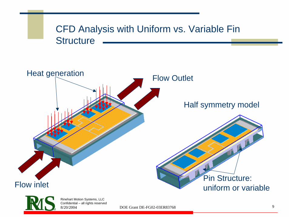
CFD Analysis with Uniform vs. Variable Fin Structure
Flow inlet
Flow OutletHeat generation
Half symmetry model
Pin Structure: uniform or variable

8/20/2004 DOE Grant DE-FG02-03ER83768 10R SM TM
Rinehart Motion Systems, LLC Confidential – all rights reserved
Model 1: Uniform Pin Structure
Velocity plot
Temperature cross section
Different sized pins, smaller downstream
Temp Surface plot: solids

8/20/2004 DOE Grant DE-FG02-03ER83768 11R SM TM
Rinehart Motion Systems, LLC Confidential – all rights reserved

8/20/2004 DOE Grant DE-FG02-03ER83768 12R SM TM
Rinehart Motion Systems, LLC Confidential – all rights reserved
Velocity plot
Temperature cross section
Different sized pins, smaller downstream
Temp Surface plot: solids
Model 2: Non-Uniform Pin Structure

8/20/2004 DOE Grant DE-FG02-03ER83768 13R SM TM
Rinehart Motion Systems, LLC Confidential – all rights reserved
Improved Temperature Difference

8/20/2004 DOE Grant DE-FG02-03ER83768 14R SM TM
Rinehart Motion Systems, LLC Confidential – all rights reserved
Fluid Flow Analysis
Uniform velocity Field once the fluid enters the area under the die
Note the complex shape of the fluid flow control features in the molded channel

8/20/2004 DOE Grant DE-FG02-03ER83768 15R SM TM
Rinehart Motion Systems, LLC Confidential – all rights reserved
Fluid Flow Analysis
Same model as previous slide, but with bases included, to illustrate how the fins affect the flow
Detail

8/20/2004 DOE Grant DE-FG02-03ER83768 16R SM TM
Rinehart Motion Systems, LLC Confidential – all rights reserved
Fluid Flow Analysis
Pressure Field
Note the 5 PSI pressure dropVelocity Field

8/20/2004 DOE Grant DE-FG02-03ER83768 17R SM TM
Rinehart Motion Systems, LLC Confidential – all rights reserved
Proposed Structure of the new Inverter

8/20/2004 DOE Grant DE-FG02-03ER83768 18R SM TM
Rinehart Motion Systems, LLC Confidential – all rights reserved
100kW Inverter Volume
330 x 85 x 170 mm = 4.8L for 100kW
Specific Volume is 48mL/kW
8/20/2004 DOE Grant DE-FG02-03ER83768 19R SM TM
Rinehart Motion Systems, LLC Confidential – all rights reserved
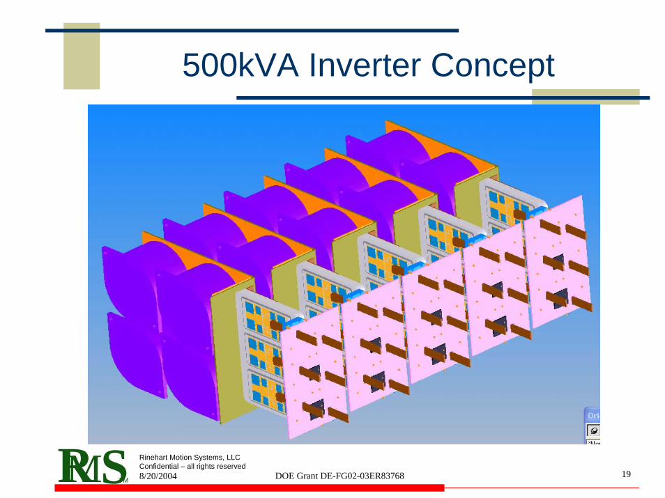
500kVA Inverter Concept

8/20/2004 DOE Grant DE-FG02-03ER83768 20R SM TM
Rinehart Motion Systems, LLC Confidential – all rights reserved
AccomplishmentsHave narrowed the field of candidate materials to three promising alternatives worth pursuingHave developed a novel configuration and process for a new non-isotropic composite, AlSiC – GHave developed non-uniform pin composition and pin location techniques to reduce die-to-die temperature differences
This should greatly enhance performance and reliability of parallel operated IGBTs and Diodes
Have designed a 100kW inverter with low cost injection molded materials everywhere high thermal or electrical conductivity is not required – cost and weight reductions

8/20/2004 DOE Grant DE-FG02-03ER83768 21R SM TM
Rinehart Motion Systems, LLC Confidential – all rights reserved
Next StepsReturn to Agenda
Complete the detailed design of the heat exchanger componentsFabricate Substrate, Base and Channel partsBuild prototype assembliesTest prototype assembliesComplete the inverter package detail designFabricate inverter package components and hardwareDesign and fabricate Control and Gate Drive PCBsBuild prototype inverter systemPerform initial inverter system testing and evaluation