Embed Size (px)
Citation preview

Progress on “pico” air vehicles
R.J. Wood, B. Finio, M. Karpelson, K. Ma, N.O. Perez-Arancibia, P.S. Sreetharan,H. Tanaka, and J.P. Whitney
Abstract As the characteristic size of a flying robot decreases, the challenges forsuccessful flight revert to basic questions of fabrication, actuation, fluid mechanics,stabilization, and power - whereas such questions have in general been answeredfor larger aircraft. When developing a flying robot on the scale of a common house-fly, all hardware must be developed from scratch as there is nothing “off-the-shelf”which can be used for mechanisms, sensors, or computation that would satisfy theextreme mass and power limitations. This technology void also applies to techniquesavailable for fabrication and assembly of the aeromechanical components: the scaleand complexity of the mechanical features requires new ways to design and pro-totype at scales between macro and MEMS, but with rich topologies and materialchoices one would expect in designing human-scale vehicles. With these challengesin mind, we present progress in the essential technologies for insect-scale robots, or“pico” air vehicles.
1 Introduction
Over the past two plus decades there have been multiple research projects aimedat the development of a flapping-wing robotic insect. These include a butterfly-likeornithopter from the University of Tokyo [1], the “Micromechanical Flying Insect”project at U.C. Berkeley [2, 3], and the Harvard “RoboBee” project [4]. These ef-forts are motivated by tasks such as hazardous environment exploration, search andrescue, and assisted agriculture - similar to the tasks cited for many autonomousrobots regardless of scale or morphology. Using swarms of small, agile, and poten-tially disposable robots for these applications could have benefits over larger, morecomplex individual robots with respect to coverage and robustness to robot failure.But the interest in these types of robots goes well beyond the expected tasks; useas tools to study open scientific questions (e.g. fluid mechanics of flapping flight,control strategies for computation and sensor limited systems) and the necessarytechnological achievements that must accompany these projects are the real motiva-tions.
Work in unmanned aerial vehicles has a rich history that spans from scientificinquiry to congressional policy1. In 1997, the United States Defense Advanced Re-
The authors are with the Harvard School of Engineering and Applied Sciences, 33 Oxford St,Cambridge, MA 02138, e-mail: [email protected]
1 Section 220 of the National Defense Authorization Act for Fiscal Year 2001 states that, “It shallbe the goal of the Armed Forces to achieve the fielding of unmanned, remotely controlled technol-ogy such that... by 2010, one-third of the aircraft in the operational deep strike force aircraft fleetare unmanned” [5].
1
2 Wood, et al.
search Projects Agency (DARPA) announced its “micro air vehicle” program whichdefined an MAV as being 15cm or less in largest linear dimension, have a rangeof 10km, peak velocities over 13m/s, and operate for more than 20 minutes2. Per-formers in this program developed multiple successful MAV prototypes includingthe Black Widow and Microbat [6] as well as some of the first examples of piezo-electrically actuated MAVs [7, 2]. In 2005, DARPA again pushed the limits of aerialrobotics by announcing the “Nano Air Vehicle” program3 which had the require-ments of 10 gram or less vehicles with 7.5cm maximum dimension, able to fly 1kmor more. Results include the 16 cm, 19 gram “Nano Hummingbird” from Aerovi-ronment4, the maple seed-inspired Lockheed “Samarai”5, and a coaxial helicopterfrom a Draper Labs led team6. There are also a number of recent commercially-available flapping-wing toy ornithopters and RC helicopters on the scale of microair vehicles such as the Silverlit ‘iBird’ and the Wowwee Flytech toys7.
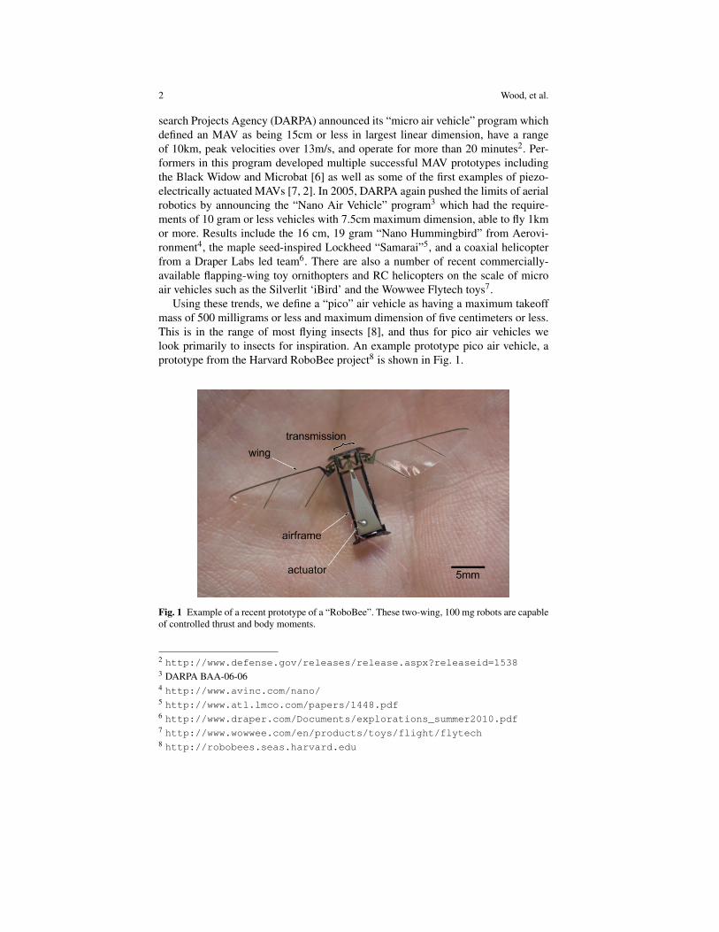
Using these trends, we define a “pico” air vehicle as having a maximum takeoffmass of 500 milligrams or less and maximum dimension of five centimeters or less.This is in the range of most flying insects [8], and thus for pico air vehicles welook primarily to insects for inspiration. An example prototype pico air vehicle, aprototype from the Harvard RoboBee project8 is shown in Fig. 1.
Fig. 1 Example of a recent prototype of a “RoboBee”. These two-wing, 100 mg robots are capableof controlled thrust and body moments.
2 http://www.defense.gov/releases/release.aspx?releaseid=15383 DARPA BAA-06-064 http://www.avinc.com/nano/5 http://www.atl.lmco.com/papers/1448.pdf6 http://www.draper.com/Documents/explorations_summer2010.pdf7 http://www.wowwee.com/en/products/toys/flight/flytech8 http://robobees.seas.harvard.edu

Progress on “pico” air vehicles 3
Regardless of the classification, the challenges of creating effective flying robotsspan many disciplines. For example, fluid mechanics changes as a function of char-acteristic length and velocity: micro air vehicles on the scale of large birds (Re >10,000) exist in a regime of turbulent flow and steady lift to drag ratios greaterthan 10 [8]. Nano air vehicles may exist in the transition region (1000 < Re <10,000) and thus the impact of boundary layer separation (and potential reattach-ment) becomes particularly relevant. Whereas for pico air vehicles (Re < 3000),the flow is almost entirely laminar and thus so-called unsteady mechanisms can beemployed to enhance lift beyond what would be achievable from constant velocityalone. Nonetheless, it appears that the energetic cost for flight - when considering ametric similar to cost of transport - increases with decreasing characteristic length.Where we could expect a larger-scale aircraft (tens of meters in characteristic di-mension) to stay aloft for many hours or even days, flight times for micro, nano, andpico air vehicles are expected to be on the order of an hour, a few tens of minutes,and less than ten minutes respectively [9].
Similar scaling trends also exist for device manufacturing. It is useful to makea distinction between feature size and characteristic size as pertaining to a vehicle:the former refers to the smallest dimension of the mechanical components of thesystem - the pitch of gear teeth, thickness of a constituent material, and length ofa flexure are examples - while the latter is more descriptive of the overall scale ofthe vehicle and can refer to the wingspan, chord length, or some similar quantity.We make the argument that as the characteristic size of a vehicle is reduced, fea-sible approaches to fabrication and assembly of the various propulsion and controlmechanisms makes a distinct transition between more standard approaches using“off-the-shelf” components and machining and assembly tools to requiring entirelynovel methods. This is one of the fundamental challenges to creating a pico airvehicle. As the feature sizes of the mechanical components are decreased belowaround 10-100 microns, the designer can no longer rely on standard macro-scalemachining techniques. Even high resolution CNC mills9, with positioning accuracydown to one micron require end mills which are rare or non-existent below 50-100 microns. Furthermore, the physics of scaling dictates that as the feature size isdecreased, area-dependent forces (e.g. friction, electrostatic, and van der Waals) be-come dominant, causing more traditional bearing joints to be very lossy with respectto power transmission [10]. Similar arguments can be made for transducers. As thefeature size is reduced, friction losses and limits on current density decrease theeffectiveness of electromagnetic motors [10]. For example, the induction motor ina Tesla Roadster can produce over 7kW/kg at nearly 90% transduction efficiency10
whereas the smallest DC motors commercially available can produce 39W/kg at lessthan 18% efficiency11,12. A deeper discussion of actuator geometries and materials
9 For example, Microlution 5100: http://microlution-inc.com/products/5100.php10 http://www.teslamotors.com/roadster/specs11 SBL02-06H1 from Namiki: http://www.namiki.net/product/dcmotor/pdf/sbl02-06ssd04_01_e.pdf12 Note that this does not include drive circuitry, which is also exacerbated at small scales.
4 Wood, et al.
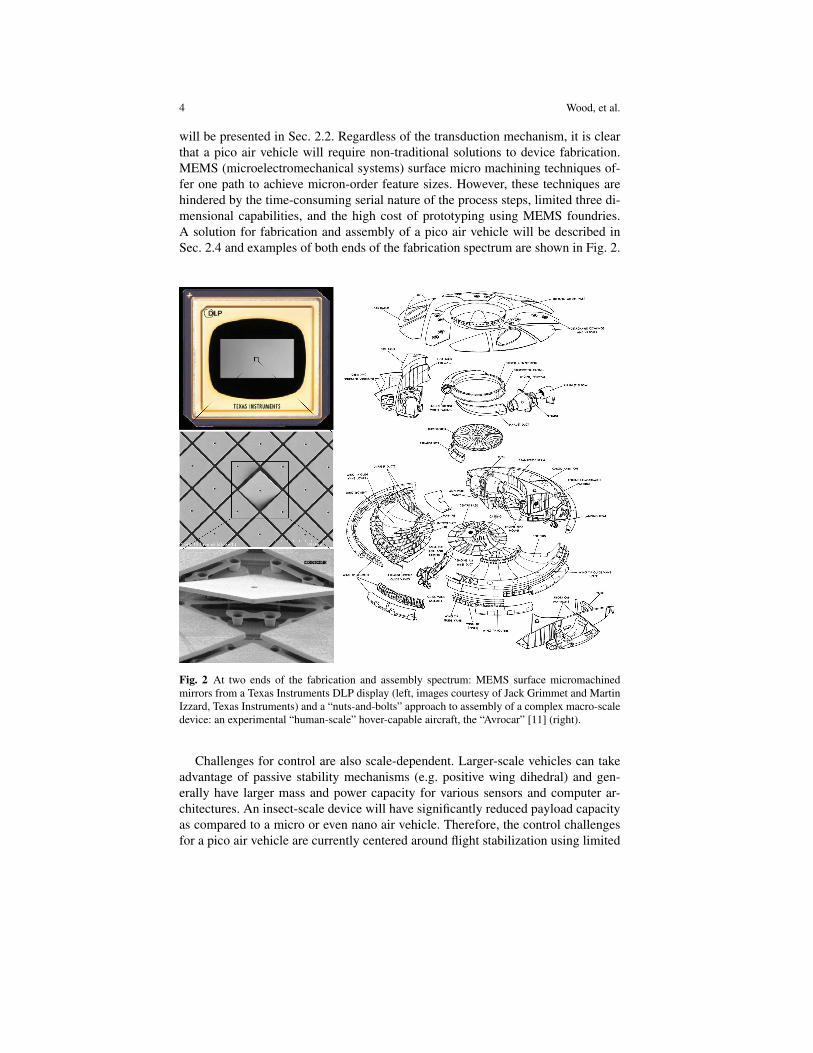
will be presented in Sec. 2.2. Regardless of the transduction mechanism, it is clearthat a pico air vehicle will require non-traditional solutions to device fabrication.MEMS (microelectromechanical systems) surface micro machining techniques of-fer one path to achieve micron-order feature sizes. However, these techniques arehindered by the time-consuming serial nature of the process steps, limited three di-mensional capabilities, and the high cost of prototyping using MEMS foundries.A solution for fabrication and assembly of a pico air vehicle will be described inSec. 2.4 and examples of both ends of the fabrication spectrum are shown in Fig. 2.
Fig. 2 At two ends of the fabrication and assembly spectrum: MEMS surface micromachinedmirrors from a Texas Instruments DLP display (left, images courtesy of Jack Grimmet and MartinIzzard, Texas Instruments) and a “nuts-and-bolts” approach to assembly of a complex macro-scaledevice: an experimental “human-scale” hover-capable aircraft, the “Avrocar” [11] (right).
Challenges for control are also scale-dependent. Larger-scale vehicles can takeadvantage of passive stability mechanisms (e.g. positive wing dihedral) and gen-erally have larger mass and power capacity for various sensors and computer ar-chitectures. An insect-scale device will have significantly reduced payload capacityas compared to a micro or even nano air vehicle. Therefore, the control challengesfor a pico air vehicle are currently centered around flight stabilization using limited

Progress on “pico” air vehicles 5
sensing and computation capabilities. This is in contrast to “higher-level” controlproblems of autonomous navigation [12] and coordination of multiple unmannedair vehicles [13].
Beyond aeromechanics, actuation, fabrication, and control, there are numerousadditional issues including power, system-level design, integration, and mass pro-duction. Thus the challenges for a pico air vehicle are daunting, yet form a set ofexciting and well-posed engineering questions and scientific opportunities. The re-mainder of this article will discuss recent progress in a number of these areas.
2 Overview of a pico air vehicle
This article will focus on some of the key components of a flapping-wing pico airvehicle, as shown in Fig. 3, based on the design of the Harvard RoboBee. Thesecomponents make up the majority of the power and mass budget for the pico airvehicle, which is shown in Fig. 4 for a hypothetical 100 milligram robot. Note thedominance of battery and actuator mass and actuator power, which is indicative ofthe energetic cost of flight at these scales.
Fig. 3 Components of a pico air vehicle.
2.1 Aeromechanics
Due to scaling of fluid properties, insects operate in a way fundamentally differentfrom conventional aircraft. Although there are many, sometimes subtle, differencesbetween the flight apparatuses of individual species, in general, insects have one ortwo pairs of wings, driven in multiple rotational degrees of freedom by flight mus-culature, and powered by metabolic processes which convert chemical energy for
6 Wood, et al.
Fig. 4 Mass (left) and power (right) budgets for a 100 milligram robot, derived using the methodin [9].
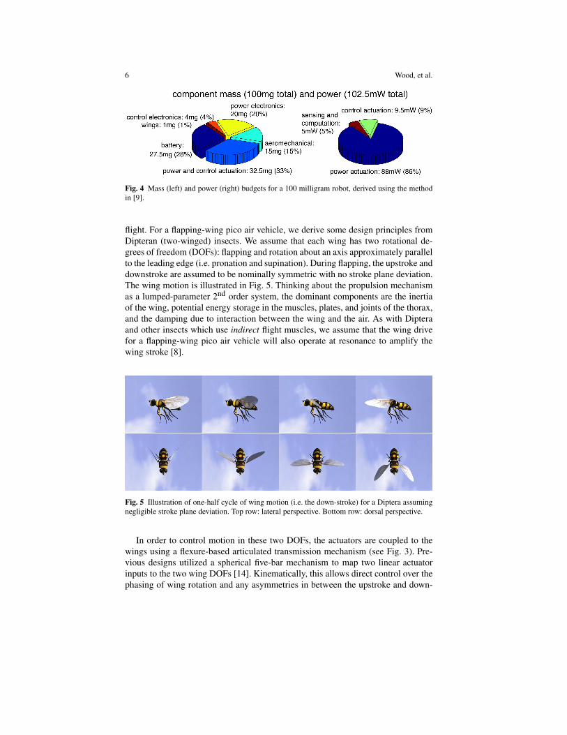
flight. For a flapping-wing pico air vehicle, we derive some design principles fromDipteran (two-winged) insects. We assume that each wing has two rotational de-grees of freedom (DOFs): flapping and rotation about an axis approximately parallelto the leading edge (i.e. pronation and supination). During flapping, the upstroke anddownstroke are assumed to be nominally symmetric with no stroke plane deviation.The wing motion is illustrated in Fig. 5. Thinking about the propulsion mechanismas a lumped-parameter 2nd order system, the dominant components are the inertiaof the wing, potential energy storage in the muscles, plates, and joints of the thorax,and the damping due to interaction between the wing and the air. As with Dipteraand other insects which use indirect flight muscles, we assume that the wing drivefor a flapping-wing pico air vehicle will also operate at resonance to amplify thewing stroke [8].
Fig. 5 Illustration of one-half cycle of wing motion (i.e. the down-stroke) for a Diptera assumingnegligible stroke plane deviation. Top row: lateral perspective. Bottom row: dorsal perspective.
In order to control motion in these two DOFs, the actuators are coupled to thewings using a flexure-based articulated transmission mechanism (see Fig. 3). Pre-vious designs utilized a spherical five-bar mechanism to map two linear actuatorinputs to the two wing DOFs [14]. Kinematically, this allows direct control over thephasing of wing rotation and any asymmetries in between the upstroke and down-

Progress on “pico” air vehicles 7
stroke. However, dynamic coupling between the two degrees of freedom createschallenges for controlled trajectories at the flapping resonant frequency. Instead, anunder-actuated version of the transmission includes a passive flexure hinge at thewing base such that flapping is commanded by a single power actuator and rota-tion is passive [15]. Tuning the dynamics of the system at design time places therotational resonance well above the flapping resonance such that we can assumequasi-static wing rotation while driving the actuator at the first flapping resonantfrequency. There is evidence that wing rotation in some insects is driven by inertialand aerodynamic forces, as opposed to directly activated by thoracic musculature[16, 17, 18].
The presence of unsteady flow features arising from wing-wake and wing-winginteractions, aeroelastic coupling between fluid pressure and wing bending [19, 20],and the significance of vortex formation and shedding [21] result in challenges fora succinct description of the relationship between wing properties (geometric, in-ertial, and elastic), wing motions and deformation, and resulting flow and forcegeneration. To study the aeromechanics of flapping-wing flight, researchers haveemployed a variety of methods including dynamic scaling [21], computational fluiddynamics (CFD) methods [22], and direct biological observation [23]. Each of thesehas led to significant insights into the details of flow structure, performance of manyflying insects, and the function of various morphological features. A combination ofthese methods, the blade-element method [24], merges quasi-steady flow analysiswith empirically-fit force and torque coefficients which hide all the unsteady termsbehind these coefficients. This has allowed designers to study a variety of wingmorphologies and trajectories. However, in some cases, the aeroelastic interactionbetween strain energy in the airfoil and fluid pressure may have a non-negligibleeffect on the dynamics and energetics of the vehicle. In such cases, it is valuable tostudy the fluid mechanics using either a moving-mesh CFD code or at-scale experi-ments which do not make any scaling assumptions on wing compliance.
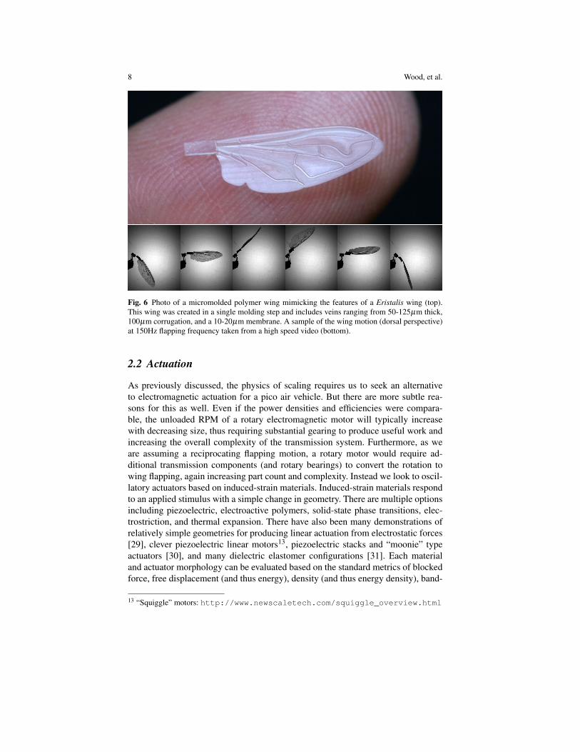
Given the ability to manufacture insect-scale airfoils, such as the Eristalis wingin Fig. 6 [25], and actuate with insect-like trajectories and wingbeat frequencies,we have begun multiple experiments which are aimed at a deeper understanding ofthe fluid mechanics for a pico air vehicle with emphasis on learning design rules toenhance aerodynamic efficiency - and thus overall performance of the robot. Recentexperiments include:
• Multiple methods to create biomimetic airfoils and verification that the staticcharacteristics are consistent with biological wings [26, 25].
• Established a blade-element based model of under-actuated flapping dynamics(i.e. passive rotation) and validated using a custom-made single flapping-wing,high resolution force sensing [27], and high speed motion reconstruction [24].
• Explored the function of distributed vs localized wing compliance on lift forcegeneration [28].
8 Wood, et al.
Fig. 6 Photo of a micromolded polymer wing mimicking the features of a Eristalis wing (top).This wing was created in a single molding step and includes veins ranging from 50-125µm thick,100µm corrugation, and a 10-20µm membrane. A sample of the wing motion (dorsal perspective)at 150Hz flapping frequency taken from a high speed video (bottom).
2.2 Actuation
As previously discussed, the physics of scaling requires us to seek an alternativeto electromagnetic actuation for a pico air vehicle. But there are more subtle rea-sons for this as well. Even if the power densities and efficiencies were compara-ble, the unloaded RPM of a rotary electromagnetic motor will typically increasewith decreasing size, thus requiring substantial gearing to produce useful work andincreasing the overall complexity of the transmission system. Furthermore, as weare assuming a reciprocating flapping motion, a rotary motor would require ad-ditional transmission components (and rotary bearings) to convert the rotation towing flapping, again increasing part count and complexity. Instead we look to oscil-latory actuators based on induced-strain materials. Induced-strain materials respondto an applied stimulus with a simple change in geometry. There are multiple optionsincluding piezoelectric, electroactive polymers, solid-state phase transitions, elec-trostriction, and thermal expansion. There have also been many demonstrations ofrelatively simple geometries for producing linear actuation from electrostatic forces[29], clever piezoelectric linear motors13, piezoelectric stacks and “moonie” typeactuators [30], and many dielectric elastomer configurations [31]. Each materialand actuator morphology can be evaluated based on the standard metrics of blockedforce, free displacement (and thus energy), density (and thus energy density), band-
13 “Squiggle” motors: http://www.newscaletech.com/squiggle_overview.html
Progress on “pico” air vehicles 9
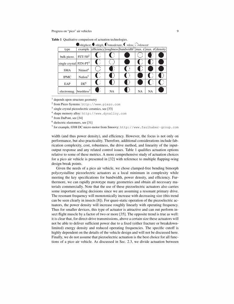
Table 1 Qualitative comparison of actuation technologies.
=highest, =high, =moderate, =low, =lowesttype example efficiency toughness bandwidth1 max. ε max. σ density
bulk piezo. PZT-5H2
single crystal PZN-PT3
SMA Nitinol4
IPMC Nafion5
EAP DE6
electromag. brushless7 NA NA NA
1 depends upon structure geometry2 from Piezo Systems: http://www.piezo.com3 single crystal piezoelectric ceramics, see [33]4 shape memory alloy: http://www.dynalloy.com5 from DuPont, see [34]6 dielectric elastomers, see [31]7 for example, 0308 DC micro-motor from Smoovy: http://www.faulhaber-group.com
width (and thus power density), and efficiency. However, the focus is not only onperformance, but also practicality. Therefore, additional considerations include fab-rication complexity, cost, robustness, the drive method, and linearity of the input-output response and any related control issues. Table 1 qualifies actuation optionsrelative to some of these metrics. A more comprehensive study of actuation choicesfor a pico air vehicle is presented in [32] with reference to multiple flapping-wingdesign break points.
Given the needs of a pico air vehicle, we chose clamped-free bending bimorphpolycrystalline piezoelectric actuators as a local minimum in complexity whilemeeting the key specifications for bandwidth, power density, and efficiency. Fur-thermore, we can rapidly prototype many geometries and obtain all necessary ma-terials commercially. Note that the use of these piezoelectric actuators also carriessome important scaling decisions since we are assuming a resonant primary drive.The resonant frequency will monotonically increase with decreasing size (this trendcan be seen clearly in insects [8]). For quasi-static operation of the piezoelectric ac-tuators, the power density will increase roughly linearly with operating frequency.Thus for smaller devices, this type of actuator is attractive and can out perform in-sect flight muscle by a factor of two or more [35]. The opposite trend is true as well:it is clear that, for direct-drive transmissions, above a certain size these actuators willnot be able to deliver sufficient power due to a fixed (either fracture or breakdown-limited) energy density and reduced operating frequencies. The specific cutoff ishighly dependent on the details of the vehicle design and will not be discussed here.Finally, we do not assume that piezoelectric actuation is the best choice for all func-tions of a pico air vehicle. As discussed in Sec. 2.3, we divide actuation between

10 Wood, et al.
power delivery and control. The previous discussions have focused on maximizingresonant power delivery in order to generate thrust to maintain flight, however therequirements for a control actuator could be rather different than a power actuator,thus a hybrid solution is a potentially viable option.
2.3 Control
The challenges for control for a pico air vehicle are not in planning and navigation,but rather more fundamental topics of stabilization, sensing, and electromechani-cal design. Flapping-wing robots similar to the one in Fig. 1 are designed such thatthe mean lift vector passes through the center of mass and the periodic drag forcesare symmetric on the upstroke and downstroke, thus there are nominally zero bodytorques during flight. However, fabrication errors and external disturbances can eas-ily excite instabilities in the roll, pitch, or yaw angles which need to be activelysuppressed. Fig. 7 displays a typical behavior in the absence of any controller orconstraints on the body degrees of freedom for a flapping-wing pico air vehicle. Itis worth noting that the robot in Fig. 7 survived over ten such crashes without anydamage, which demonstrates the robustness of the materials and components thatconstitute the robot.
t = 0.000s t = 0.111s t = 0.165s t = 0.204s t = 0.252s1cm
Fig. 7 When driven open-loop, the RoboBee prototypes are very unstable in body rotations andcrash shortly after takeoff.
Our control efforts to date have concentrated on (a) development of the thoracicmechanics to enable modulation of wing trajectories and hence body torques, (b)exploration of appropriate sensor technologies, and (c) methodologies for controllersynthesis and related demonstrations. Recent progress in these areas include:
• We have demonstrated the ability to generate lift greater than body mass and per-form uncontrolled takeoff experiment such as shown in Fig. 7 [4]. This providesthe baseline aeromechanical design and allows us to quantify the thrust the robotcan achieve to help bound payload for sensing and power.
• The original designs presented in [4] only had the ability to control thrust andone body torque (i.e. pitch torques). We have demonstrated the ability to gener-ate bilateral asymmetry in stroke amplitude using multiple thoracic mechanicsconfigurations [36, 37]. This involves a morphological separation of power andcontrol actuation similar to the role of the indirect and direct flight muscles inthe thoracic mechanics of Dipteran insects [38].

Progress on “pico” air vehicles 11
• Similarly, we have performed experiments with stroke plane deviation as an al-ternative method for torque generation in [39].
• Beyond modulating the wing trajectory, we have performed torque measurementexperiments which verify that there is a one-to-one relationship between dorso-ventral mean stroke angle bias and the resulting pitch torque [40].
• Through collaborations with Centeye, Inc14, insect-inspired optical flow sensorshave been integrated on-board a gliding micro air vehicle [41].
• Work at U.C. Berkeley has prototyped a number of insect-inspired inertial andhorizon-detection sensors such as a biomimetic haltere (similar to the Coriolisforce sensing structures in Diptera [42]) and photoreceptive ocelli similar to thehorizon detection sensors in insects [43].
• Finally, we have implemented an adaptive control scheme to control the meanlift force during flapping [44].
These efforts are primarily focused on the standard feedback control strategyin which a disturbance is detected by a proprioceptive sensor, a computer choosesa compensatory action according to some control law, and the action is then im-plemented by a system of amplifiers and electromechanical structures. We refer todevices which perform such complex tasks without the intervention of electricalcircuits (i.e. analog or digital computers) as examples of mechanical intelligence.There are many everyday examples including windshield wipers, whippletrees, andautomobile differentials. In these examples, feedback control is performed as aconsequence of the mechanical design. For example, automobile differentials au-tomatically distribute equal torques to the wheels regardless of differences in wheelvelocities. We have applied this concept to the passive regulation of wing mo-tions by a modified version of the flexure-based transmission called PARITy: “Pas-sive Aeromechanical Regulation of Unbalanced Torques” [45]. The PARITy designequally distributes torques to the wings in response to perturbations, due to eitherexternal disturbances or fabrication errors, without the need for sensors or compu-tation. This allows an active controller to operate on a much longer time scale sinceshort time scale perturbations are eliminated, thereby reducing the required sensorbandwidth and computation power.
2.4 Fabrication
The integrated circuit revolution of the 1950s and 1960s now enables the majorityof the consumer electronics that are enjoyed daily. As these techniques evolved inthe 1980s to include electromechanical components, an even greater space of ap-plications emerged including sensors, optics, and even actuation [46]. Microrobotshave been made using MEMS surface and bulk micromachining techniques [47, 48].However, there are many drawbacks to using integrated circuit (IC) and MEMStechnologies to create a pico air vehicle. First is the dramatic difference betweenthe material properties of silicon and insect tissue: the former being rigid and brittle
14 http://www.centeye.com

12 Wood, et al.
while the latter exhibits a large range of material properties, is generally quite re-silient, and is approximately the density of water. Second, although the suite of tech-niques for high resolution machining is an appealing aspect of MEMS processes,the resulting structures are typically “2.5D”, with high aspect ratio componentsbeing extremely challenging in terms of machining or requiring hinged structures[49]. Finally, although MEMS foundries exist (e.g. the Multi-User MEMS Process,MUMPS15 and Sandia’s SUMMiT16), cost and turnaround time are generally pro-hibitive to rapid prototyping. With the advent of mesoscopic manufacturing methods[50], we have demonstrated key components of the flight apparatus of robotic insects[51, 15] and recently the first demonstration of a 60 milligram flapping-wing devicewhich can produce thrust greater than its body weight [4] has proven the feasibilityof creating insect-scale flying robots using these techniques.
Mesoscopic manufacturing based on lamination and folding is depicted in Fig. 8.Here a spherical five-bar mechanism is created in three steps. First, the constituentmaterials - typically thin sheets of polymers, metals, ceramics, or composites - arelaser micromachined to the desired planform geometries. These layers are thenaligned and laminated using thermoset sheet adhesives and a heated press. Sec-ond, the quasi-planar devices are released using a final laser machining step. Lastly,the devices are folded into their final configuration. In the case in Fig. 8, tabs andslots are integrated to assist with alignment during folding, although there are othermethods to ensure precision in this final step including fixturing, surface tension,differential thermal expansion, and even embedded actuation [52]. This process en-ables the development of articulated components with any number of DOFs, layeredactuators such as the piezoelectric bending actuators described in Sec. 2.2, and in-tegrated electronics, all with feature sizes ranging from micron to centimeter. Theconcept of folding as an assembly process has been further developed into the alarger space of applications for “Programmable Matter” using robotic origami toproduce arbitrary shapes and functional structures [53].
2.5 Power
The power source for a pico air vehicle is the most significant delimiter to flighttime [9]. Options for power storage include electrochemical (i.e. batteries and fuelcells [54]), electrostatic (i.e. capacitors and supercapacitors), and mechanical (i.e.elastic strain energy)17. As with all components, practicality is a fundamental con-sideration. Existing batteries have poor energy storage (approximately 500J/g basedon existing small-scale lithium batteries from Fullriver18) compared to fuels such asgasoline which can be two orders of magnitude greater. But energy density alone isnot sufficient to describe the effectiveness of a candidate power source. Conversionefficiency, storage/packaging, and operating conditions should also be considered.
15 http://www.memscapinc.com16 http://www.mems.sandia.gov/tech-info/summit-v.html17 Note that this only refers to storage, not transduction or harvesting.18 http://www.fullriver.com/

Progress on “pico” air vehicles 13
Fig. 8 Example of the process flow for articulated microstructures. In this example, six sphericalfive-bar linkages are created by a sequential micromachining and lamination process, then foldedinto the final configuration (inset).
There are sub-gram batteries which are commercially available18. While thelower end of this range (approximately 200mg) could be acceptable for a pico airvehicle, smaller batteries are feasible, though rare or non-existent as commercialproducts. Since the electrochemical reactions are scale-independent (at least for thescales considered here), creating smaller batteries becomes an exercise in fabricationand packaging. For example, it is possible to dice and repackage lithium-polymerbatteries in an inert atmosphere.
Power distribution efficiency is also a fundamental concern. Assuming the sourcewill have a voltage of approximately 3.7V, and using the piezoelectric actuator di-mensions from [51], the power distribution circuits for a pico air vehicle will requirea boost conversion stage with a step-up ratio in the range of 50-100 [55]. Options forboost conversion include piezoelectric transformers, charge pump ladder circuits,and electromagnetic transformers. Once the source voltage is boosted to the properlevel, the actuator drive signal is generated. Considering the low electromechanicalcoupling coefficients for many piezoelectric materials, it is essential to recover re-maining charge from one half cycle of the harmonic oscillation of the thorax anduse for the next half cycle. Charge recovery circuits for bimorph actuators havebeen developed [56] and a custom integrated circuit which generates the periodicdrive signal and coordinates charge recovery has been created and demonstratedfor a flapping-wing robot [57]. Therefore, the power source is the key remainingtechnology required to bring the pico air vehicle in Fig. 1 to power autonomy.

14 Wood, et al.
Fig. 9 Components (left) and a complete tapped-inductor-based 20 milligram boost conversioncircuit (right).
3 Next steps
The progress on pico air vehicles reported in this article is the tip of the iceberg. Thenext steps include:
• Power source: Characterization of batteries and other viable power sources (in-cluding supercapacitors and micro fuel cells) under appropriate loading condi-tions.
• Integration: The best demonstration for any core technology involves integra-tion onto a flight-worthy robot.
– On-board sensors: Continued collaboration with manufacturers of opticalflow sensors (Centeye, Inc.), aiming to demonstrate a flight-worthy sensorand use in altitude control experiments.
– On-board power electronics: Integrating the components from Fig. 9 into theairframe utilizing the layered manufacturing technique described in Sec. 2.4.
• Accelerator-based computation: The RoboBees project is exploring computearchitectures which employ highly specialized integrated circuits to perform asingle task (such as control or sensor processing) extremely efficiently.
• System-level design and optimization: Finally, while much attention has beenpaid to each component, there has been few efforts for system-level optimizationfor vehicles of this scale. The work in [9] suggests the most promising areasto focus design efforts and how improvements to the performance of any sub-system will contribute to increased flight time.
Acknowledgements This work was partially supported by the National Science Foundation(award number CCF-0926148), the Army Research Laboratory (award number W911NF-08-2-0004), the Office of Naval Research (award number N00014-08-1-0919-DOD35CAP), and the AirForce Office of Scientific Research (award number FA9550-09-1-0156-DOD35CAP). Any opin-

Progress on “pico” air vehicles 15
ions, findings, and conclusions or recommendations expressed in this material are those of theauthors and do not necessarily reflect the views of the National Science Foundation.
References
1. H. Tanaka, K. Hoshino, K. Matsumoto, I. Shimoyama, in IEEE/RSJ Int. Conf. on IntelligentRobots and Systems (Edmonton, Alberta, Canada, 2005)
2. R. Fearing, K. Chang, M. Dickinson, D. Pick, M. Sitti, J. Yan, in IEEE Int. Conf. on Roboticsand Automation (2000)
3. R. Fearing, S. Avadhanula, D. Campolo, M. Sitti, J. Yan, R. Wood, in Neurotechnology forBiomimetic Robots (The MIT Press, 2002), pp. 469–480
4. R. Wood, IEEE Transactions on Robotics 24(2) (2008)5. National Defense Authorization Act, Fiscal Year 2001 (2000). Public Law 106-398, 106th
Congress6. M. Keennon, J. Grasmeyer, in AIAA/ICAS Intl. Air and Space Symp. and Exposition: The Next
100 Years (Dayton, OH, 2003)7. A. Cox, D. Monopoli, D. Cveticanin, M. Goldfarb, E. Garcia, in J. of Intelligent Material
Systems and Structures, vol. 13 (2002), vol. 13, pp. 611–6158. R. Dudley, The Biomechanics of Insect Flight: Form, Function and Evolution (Princeton Uni-
versity Press, 1999)9. M. Karpelson, J. Whitney, G.Y. Wei, R. Wood, in IEEE/RSJ Int. Conf. on Intelligent Robots
and Systems (Taipei, Taiwan, 2010)10. W. Trimmer, J. of Sensors and Actuators 19, 267 (1989)11. Avro Canada VZ-9AV Avrocar (2010). http://www.nationalmuseum.af.mil/
factsheets/factsheet.asp?id=1085612. S. Shen, N. Michael, V. Kumar, in IEEE Int. Conf. on Robotics and Automation (Shanghai,
China, 2011)13. T. Stirling, D. Floreano, in Proceedings of the 10th International Symposium on Distributed
Autonomous Robotics Systems. (2010)14. S. Avadhanula, R. Wood, D. Campolo, R. Fearing, in IEEE Int. Conf. on Robotics and Au-
tomation (Washington, DC, 2002)15. R. Wood, in IEEE/RSJ Int. Conf. on Intelligent Robots and Systems (San Diego, CA, 2007)16. A. Ennos, J. of Experimental Biology 140, 161 (1988)17. A. Ennos, J. of Experimental Biology 140, 137 (1988)18. A. Bergou, S. Xu, Z. Wang, Journal of Fluid Mechanics 591, 321 (2007)19. S. Combes, T. Daniel, J. of Experimental Biology 206(17), 2989 (2003)20. S. Combes, T. Daniel, J. of Experimental Biology 206(17), 2999 (2003)21. M. Dickinson, F.O. Lehmann, S. Sane, Science 284, 1954 (1999)22. R. Mittal, G. Iaccarino, Ann. Rev. Fluid Mechanics 37, 239 (2005)23. C. Ellington, C. van der Berg, A. Willmott, A. Thomas, Nature 384, 626 (1996)24. J. Whitney, R. Wood, J. Fluid Mechanics 660, 197 (2010)25. H. Tanaka, R. Wood, J. Micromechanics and Microengineering 20(7) (2010)26. J. Shang, S. Combes, B. Finio, R. Wood, Bioinspir. Biomim. 4(036002) (2009)27. R. Wood, K.J. Cho, K. Hoffman, J. Smart Materials and Structures 18(125002) (2009)28. H. Tanaka, J. Whitney, R. Wood, J. Integrative & Comparative Bio. 51(1), 142 (2011)29. W. Tang, T.C. Nguyen, M. Judy, R. Howe, J. of Sensors and Actuators A: Physical 21(1–3),
328 (1990)30. R. Newnham, A. Dogan, Q. Xu, K. Onitsuka, J. Tressler, S. Yoshikawa, in Proc. IEEE Ultra-
sonics Symp., vol. 1 (Baltimore, MD, 1993), vol. 1, pp. 509–51331. R. Pelrine, P. Sommer-Larsen, R. Kornbluh, R. Heydt, G. Kofod, Q. Pei, P. Gravesen, in Proc.
of Int. Soc. Opt. Eng., vol. 4329 (2001), vol. 4329, pp. 335–34932. M. Karpelson, G.Y. Wei, R. Wood, in IEEE Int. Conf. on Robotics and Automation (Pasadena,
CA, 2008)

16 Wood, et al.
33. J. Yin, B. Jiang, W. Cao, IEEE Trans. on on Ultrasonics, Ferroelectrics, and Frequency Control47(1), 285 (2000)
34. S. Lee, H. Park, K. Kim, Smart Materials and Structures 14(6), 1363 (2005)35. E. Steltz, R. Fearing, in IEEE/RSJ Int. Conf. on Intelligent Robots and Systems (San Diego,
CA, 2007)36. B. Finio, J. Shang, R. Wood, in IEEE Int. Conf. on Robotics and Automation (Kobe, Japan,
2009), pp. 3449–345637. B. Finio, B. Eum, C. Oland, R. Wood, in IEEE Int. Conf. on Robotics and Automation (St.
Louis, MO, 2009)38. B. Finio, R. Wood, Bioinspir. Biomim. 5, 045006 (2010)39. B. Finio, J. Whitney, R. Wood, in IEEE/RSJ Int. Conf. on Intelligent Robots and Systems
(Taipei, Taiwan, 2010)40. B. Finio, K. Galloway, R. Wood, in IEEE/RSJ Int. Conf. on Intelligent Robots and Systems
(San Francisco, CA, 2011)41. R. Wood, S. Avadhanula, E. Steltz, M. Seeman, J. Entwistle, A. Bachrach, G. Barrows,
S. Sanders, R. Fearing, Robotics and Automation Magazine 14(2), 82 (2007)42. G. Nalbach, J. of Comparative Physiology A 173, 293 (1993)43. W. Wu, L. Schenato, R. Wood, R. Fearing, in IEEE Int. Conf. on Robotics and Automation
(Taipei, Taiwan, 2003)44. N. Perez-Arancibia, J. Whitney, R. Wood, in American Controls Conf. (San Francisco, CA,
2011)45. P. Sreetharan, R. Wood, J. Mechanical Design 132(5), 051006 (2010)46. K. Petersen, Proc. of IEEE 70(5), 420 (1982)47. R. Yeh, E. Kruglick, K. Pister, J. of Microelectrical Mechanical Systems 5(1), 10 (1996)48. B. Donald, C. Levey, C. McGray, I. Paprotny, D. Rus, J. of Microelectrical Mechanical Sys-
tems 15(1), 1 (2006)49. K. Pister, M. Judy, S. Burgett, R. Fearing, J. of Sensors and Actuators A: Physical 33, 249
(1992)50. R. Wood, S. Avadhanula, R. Sahai, E. Steltz, R. Fearing, J. of Mech. Design 130(5) (2008)51. R. Wood, E. Steltz, R. Fearing, J. of Sensors and Actuators A: Physical 119(2), 476 (2005)52. J. Paik, E. Hawkes, R. Wood, J. of Smart Materials and Structures 19(12), 125014 (2010)53. E. Hawkes, B. An, N. Benbernou, H. Tanaka, S. Kim, E. Demaine, D. Rus, R. Wood, Proc. of
the National Academy of Sciences 107(28), 12441 (2010)54. M. Tsuchiya, B. Lai, S. Ramanathan, Nature Nanotechnology 6(282) (2011)55. E. Steltz, M. Seeman, S. Avadhanula, R. Fearing, in IEEE/RSJ Int. Conf. on Intelligent Robots
and Systems (Beijing, China, 2006)56. D. Campolo, M. Sitti, R. Fearing, IEEE Trans. on Ultrasonics, Ferroelectrics and Frequency
Control 50(3), 237 (2003)57. M. Karpelson, R. Wood, G.Y. Wei, in Symp. on VLSI Circuits (Kyoto, Japan, 2011)


![[Bill Holder] Unmanned Air Vehicles an Illustrate](https://img.dokumen.tips/doc/110x75/55cf97bb550346d033934708/bill-holder-unmanned-air-vehicles-an-illustrate.jpg)