Embed Size (px)
Citation preview

Progress of RF system development for LHFW Heating and Current Drive on VEST
2016 Korea-Japan Workshop
16th. Dec. 2016
S. H. Kima, B. K. Junga, S. H. Jeonga, H. W. Leeb, B. J. Leeb, J. G. Joc, H. Y. Leec, and Y. S. Hwangc
aKorea Atomic Energy Research InstitutebKwangwoon University
cSeoul National University
2
Contents
Introduction to LHFW (Lower Hybrid Fast Wave)
- LHFW on CMA / Dispersion relation / Propagation Boundary
- Advantages & Disadvantages
Status of RF system development for LHFW experiment on VEST
- Klystron
- RF components
- Antenna
- Safety & Diagnostics
Summary

3
Introduction to LHFW(0)
The continuous current drive is one of the key issues toward steady-state
operation of tokamak fusion reactors.
Though the current drive by using bootstrap is the main strategy in tokamak,
the external current drive is still required to control pressure profile and fill the
gap between the bootstrap and target current.
Most efficient current drive ever is the LHCD which is a scheme by using slow
wave in lower hybrid resonance frequency range.
There, however, is density limit and it is hard to propagate into the central
region in high temperature plasmas due to highly damping.
Therefore, alternatives are required.
LHFW could be an alternative.

4
Introduction to LHFW(1)Lower Hybrid Fast Wave(LHFW) on CMA diagram
<H2 plasmas>
LHFW is a fast wave
between lower hybrid
resonance frequency
and electron cyclotron
resonance frequency.
2 lh ceω ω ω< <<

5
Dispersion Relation1/ 22
||
1/ 22 2|| ||
2||
( )
( )( )( )
⊥
− − ≅ − −− −
r
P N SSlow Wave
SN
N R N LFast Wave
N S
Introduction to LHFW(2)Dispersion & Propagation Boundary
Propagation Boundary
The perpendicular wave number of LHFW is less than
that of slow wave in this frequency range(LHSW).
1/ 2 3 2,
1/ 2 3 2
, 2 2||
2
exp( )
exp( )
1
r SW
i r FWce
pe
N LHSW
N N LHFWN
π η η
π η ηωω
⊥
⊥ ⊥
− −≅ −
The imaginary wave number of LHFW becomes
higher as the density increases.

6
Advantage of LHFW(1)Parallel electric field Ez to B
<Polarization of FW and SW on CMA>
It has favorable polarization for current drive compared to FWs in other frequency range.
|| ||
22
0 ||2||0|| /
12
ps sLD z
v k
FP v v dv Evk
ω
ω ωε ω πω
∞
⊥ ⊥
=
∂≅ − ∂
∫

7
It has deep penetration property in high density.
<Angle of Group Velocity Vg to magnetic field of LHFW and LHSW>
Advantage of LHFW(2)More perpendicular Vg to B
B
Vg

8
Launching condition
Accessibility condition.
( )
202
20||2 1
e
launche
ce
m LHSWen
m N LHFWe
ε ω
ε ωω
≅ −
2 20||2
14
econfluence ce
mn Neε ω≅
Disadvantage of LHFWCoupling Issue
< Propagation Boundary >
* High density is required to launch
LHFW compared to LHSW.
☞ Coupling Problem
* The same accessibility condition as LHSW
should be satisfied.
* The confluence density condition above is a more generalized accessibility condition.
2||~ ce Nω
ω

LHFW launching
LHSW launching
9
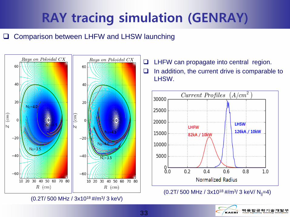
RAY tracing simulation on VEST (GENRAY)
Comparison between LHFW and LHSW launching (0.2T/ 500 MHz / 3x10¹⁸ #/m3/ 3 keV/ N||=4)
LHFW can propagate into more central region. In addition, the current drive is comparable to
LHSW.
LHFWlaunching
LHSWlaunching
100 kA / 10kW125 kA / 10kW
Normalized radius

10
RF System for LHFW experiment on VEST
Schematic of LHFW RF System
- Frequency : UHF
- Power : 10 kW(Klystron)
- Antenna : Comb-line antenna
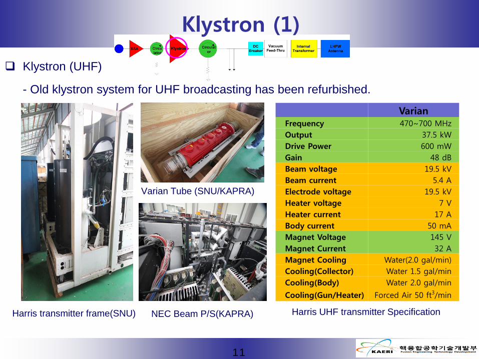
Klystron (UHF)
- Old klystron system for UHF broadcasting has been refurbished.
11
Klystron (1)
VarianFrequency 470~700 MHzOutput 37.5 kWDrive Power 600 mWGain 48 dBBeam voltage 19.5 kVBeam current 5.4 AElectrode voltage 19.5 kVHeater voltage 7 VHeater current 17 ABody current 50 mAMagnet Voltage 145 VMagnet Current 32 AMagnet Cooling Water(2.0 gal/min)Cooling(Collector) Water 1.5 gal/minCooling(Body) Water 2.0 gal/min
Cooling(Gun/Heater) Forced Air 50 ft3/min
Harris transmitter frame(SNU)
Varian Tube (SNU/KAPRA)
NEC Beam P/S(KAPRA) Harris UHF transmitter Specification
12
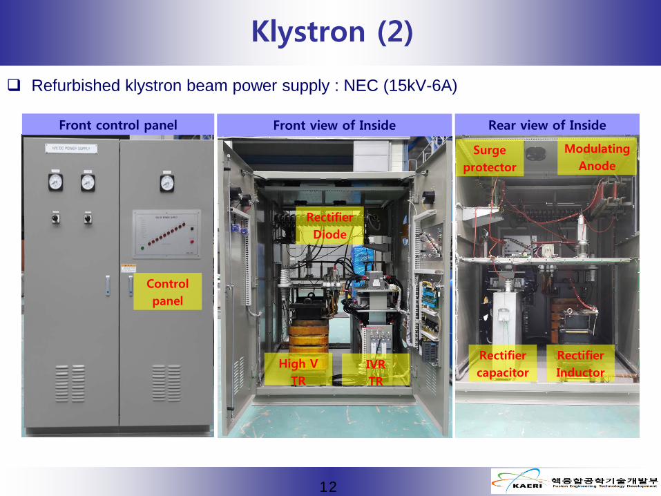
Klystron (2)
Front control panel
Controlpanel
High VTR
IVRTR
RectifierDiode
Rectifiercapacitor
RectifierInductor
ModulatingAnode
Surgeprotector
Front view of Inside
Refurbished klystron beam power supply : NEC (15kV-6A)
Rear view of Inside
13
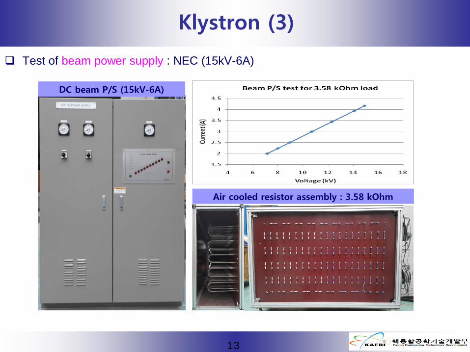
Klystron (3)
Test of beam power supply : NEC (15kV-6A)
DC beam P/S (15kV-6A)
Air cooled resistor assembly : 3.58 kOhm

Test of the vacuum degree
14
Circuit for Vacuum test
- Normal conditionGas current(Digital volt meter) < 0.5uA(5V)
- Measurement : 0.1772uA (1.772 V )- Filament : 7V -17Aa
Filament V, I
Gas I
Klystron (4)

Measurement of beam guiding magnet
15
Klystron (5)
Magnet (Harris)- Resistance : 2.5 Ohm- Water cooling : 7.6 lpm
DC P/S (In-housing)- Output : 80V-32A - Input : 220V (3ph)
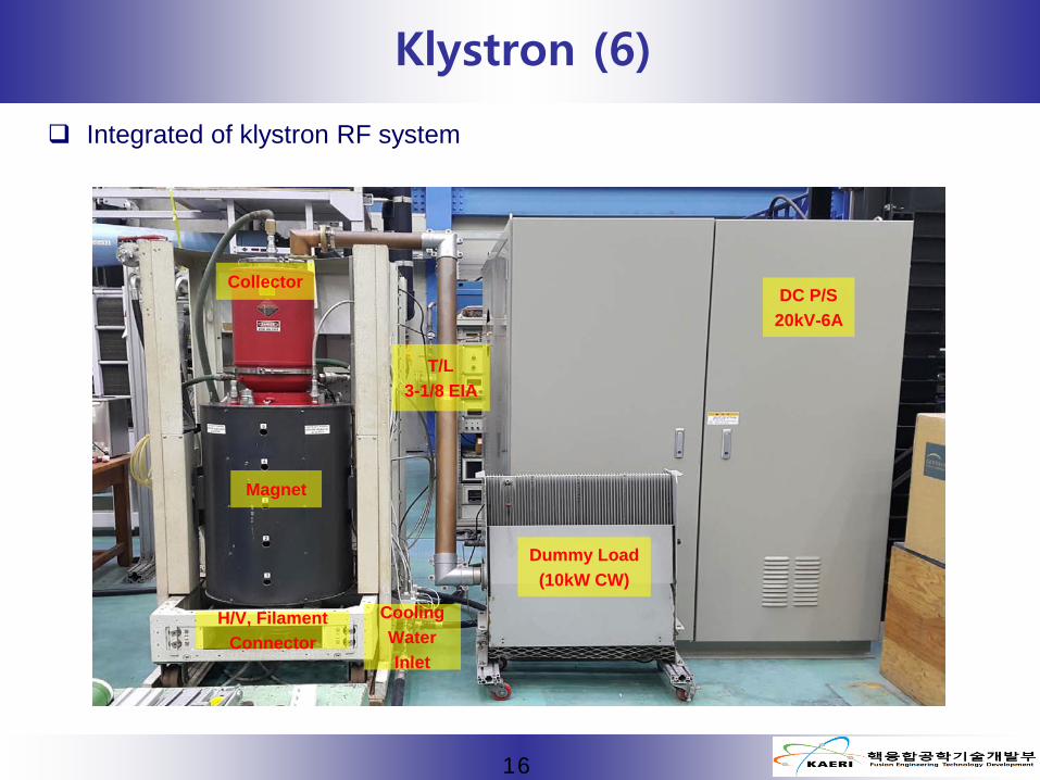
Integrated of klystron RF system
16
Klystron (6)
DC P/S20kV-6A
Dummy Load(10kW CW)
Magnet
H/V, Filament Connector
Collector
T/L3-1/8 EIA
Cooling WaterInlet
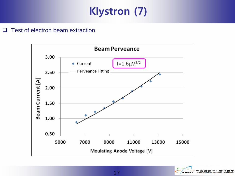
Test of electron beam extraction
17
Klystron (7)

Test of the klystron performance (frequency response & power)
18
Klystron (8)
- Beam V, I : 15 kV, 2.5 A / Mod. Anode : 13 kV- Bandwidth variation will be tried with cavity tuning.
- Beam V, I : 15 kV, 2.5 A / Mod. Anode : 13 kV- Frequency : 651 MHz- 10 kW power generation is achieved.
19
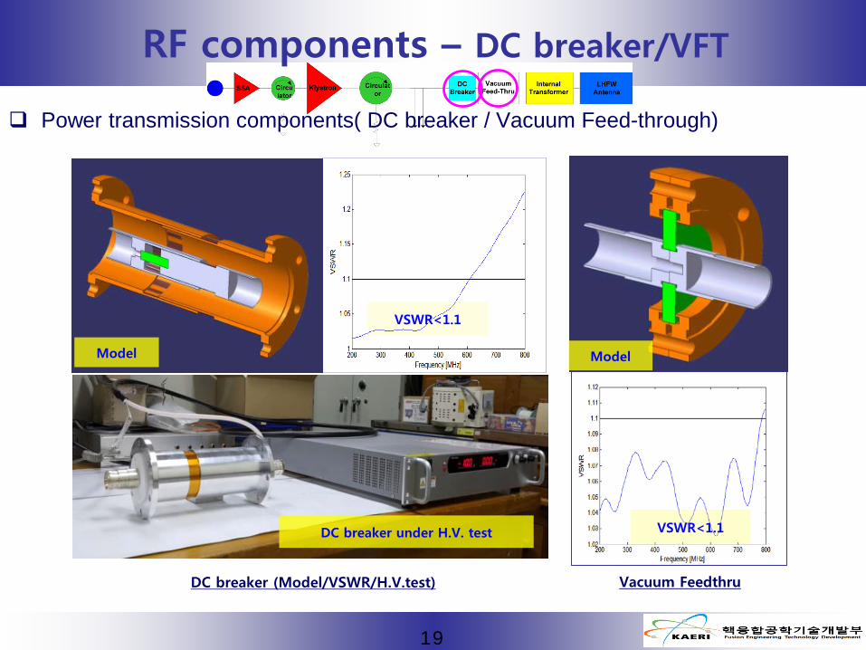
RF components – DC breaker/VFT
Power transmission components( DC breaker / Vacuum Feed-through)
Vacuum Feedthru
Model Model
VSWR<1.1
VSWR<1.1DC breaker under H.V. test
DC breaker (Model/VSWR/H.V.test)

Research Objective Consideration Points
Frequency UHF Antenna Length ~ 418 mm
Bandwidth < 50 MHz Antenna width < 200 mm
VSWR < 3 E-field ratio(Ey/Ez) 4~6
Peak n∥ 3 ~ 5 Peak E-field < 30 kV/cm
<Antenna Design>
<VEST>
LHFW Antenna(1) : comb-line
20

Antenna Structure
LHFW Antenna(2)
Faraday shield
418 mm
174 mm
Port 1 : source
Port 2 : dummy load
Comb-line current strap
128.5 mm
31.5 mm
Simulation Domain for Design(COMSOL)
Antenna in Vacuum
Plasmas or Vacuum
Perfect Matched LayerPeriodic B.C. Periodic B.C.
21

S-parameters (500 MHz) S11 = -25.6 dB S21 = -0.12 dB
S-parameters & field distribution (Vacuum load)
LHFW Antenna(3)
22
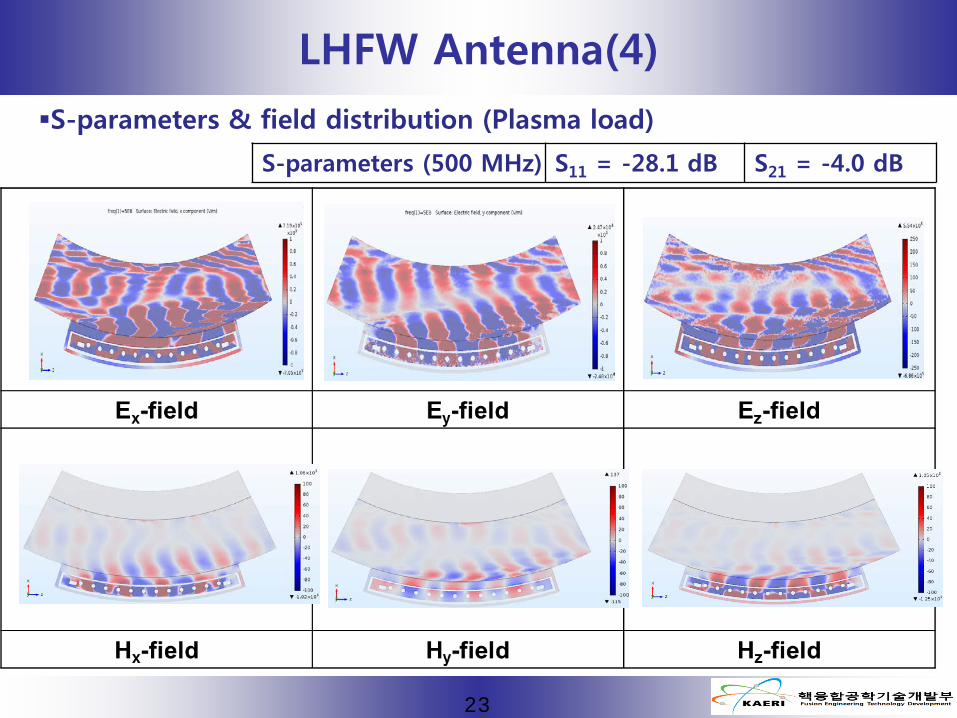
S-parameters (500 MHz) S11 = -28.1 dB S21 = -4.0 dB
S-parameters & field distribution (Plasma load)
LHFW Antenna(4)
23

470 475 480 485 490 495 500 505 510 515 520-20
-15
-10
-5
0
S11 S21
Frequency [MHz]
|S-p
aram
eter
s| [d
B]
Antenna Parallel wave number N|| ~ 3-5 S parameters : S11 <-10 dB, S21 ~ -5 dB
480~510 MHz
S21 ~ -5 dB
S11 < -10 dB
480~510 MHz
N|| : 3.5~4.7
LHFW Antenna(5)
24
470 475 480 485 490 495 500 505 510 515 5203.0
3.5
4.0
4.5
5.0
5.5
Frequency [MHz]
n ||
(Plasma load)

25
RF diagnostic (1)
Measurement : Forward/Reflected power, Voltage at antenna/TL

26
RF diagnostic (2)
Schematic of peak/phase detector & safety circuit
27
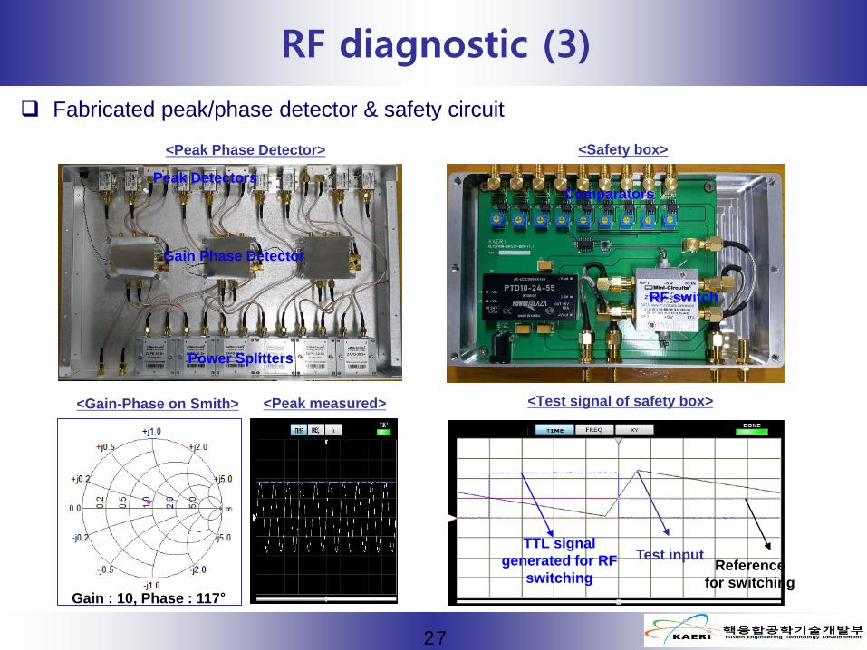
RF diagnostic (3)
Fabricated peak/phase detector & safety circuit
<Safety box>
Peak Detectors
Gain Phase Detector
Power Splitters
Comparators
RF switch
<Test signal of safety box>
TTL signal generated for RF
switchingReference
for switching
Test input
<Peak Phase Detector>
<Gain-Phase on Smith> <Peak measured>
Gain : 10, Phase : 117°

28
Summary
The steady-state operation is one of the key issues of tokamak fusion reactor.
A new concept of current drive by using a fast wave in lower hybrid frequency range(LHFW)
is suggested and the proof of principle experiment is planned on VEST.
For the experiment,
Klystron RF power system are prepared through collaboration with SNU and KAPRA .
It is refurbished and integrated, and confirmed that 10 kW power can be stably generated.
For LHFW launcher, compact comb-line antenna has been designed with COMSOL
simulation code by KWU. As a result, it is shown that it can couple 10 kW power to plasmas
with N|| 3~5.
RF diagnostic and safety device are also successfully fabricated and tested.
All RF system will be assembled after fabrication of LHFW antenna and integration
test will be carried out sooner or later.
29
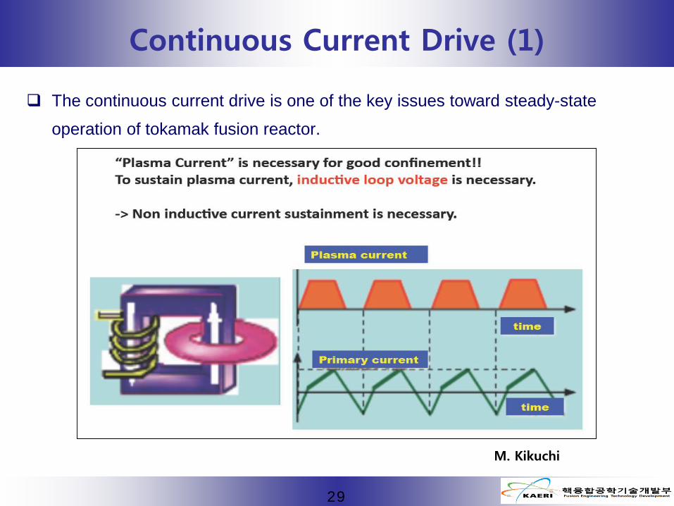
Continuous Current Drive (1)
The continuous current drive is one of the key issues toward steady-state
operation of tokamak fusion reactor.
M. Kikuchi

30
Continuous Current Drive (2)
Though the current drive by using self-generated bootstrap is the main strategy,
the external current drive is still necessary to fill the gap between the
bootstrap and target current, and to control the current and pressure profile.
Nuclear Fusion 30(1990) 343
1/ 2
~bT dnj
B drθ
ε−
1/ 2~bp
I cI
ε β
Fusion Eng. Des. 38(1997) 27

31
Continuous Current Drive (3)
The most efficient external current drive scheme is the LHCD where slow wave in
lower hybrid resonance frequency range(LHSW) is used.
It, however, has inherent density limit and the high efficiency, paradoxically, hinders it
from being used for reactor grade high temperature plasmas.
Therefore, alternatives are necessary.
Tokamaks (2004) J. Wesson
SchemeCurrent drive efficiency η :
A/m2/WMachine
LHCD ~ 0.34 (3.6 MA) JT-60U
ICRF ~ 0.04 (180 kA) DIIID
ECCD ~ 0.03 (150 kA) TCV
NB ~ 0.05 (340 kA) TFTR
32
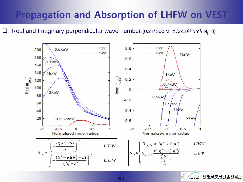
Propagation and Absorption of LHFW on VEST
Real and Imaginary perpendicular wave number (0.2T/ 500 MHz /3x1018#/m3/ N||=4)
1/ 22||
1/ 22 2|| ||
2||
( )
( )( )( )
r
P N SLHSW
SN
N R N LLHFW
N S
⊥
− − ≅ − −− −
1/ 2 3 2,
1/ 2 3 2
, 2 2||
2
exp( )
exp( )
1
r SW
i r FWce
pe
N LHSW
N N LHFWN
π η η
π η ηωω
⊥
⊥ ⊥
− −≅ −
33
RAY tracing simulation (GENRAY) Comparison between LHFW and LHSW launching
(0.2T/ 500 MHz / 3x10¹⁸ #/m3/ 3 keV/ N||=4)
LHFW can propagate into central region. In addition, the current drive is comparable to
LHSW.
(0.2T/ 500 MHz / 3x10¹⁸ #/m3/ 3 keV)

34
Coupling efficiency (1D full(cold)+WKB boundary at RHS)
Comparison between LHFW and LHSW launching
for LHFW launching for LHSW launching
Parameters Values
B0 0.2 TFrequency 500 MHzN∥ 4.0
n0 6x10¹⁵ ~ 5x10¹⁷ #/m3
nb 4x10¹⁵ #/m3
d(X2-X1) 3 cm
X1 2 cm