Embed Size (px)
Citation preview

o
o
o
o
o
Programming with DOMAIN 3D Graphics Metafile
Resource
Apollo Computer Inc. 330 Billerica Road
Chelmsford, MA 01824
Order No. 005807 Revision 00
Software Release 9.0

Copyright © 1985 Apollo Computer Inc. All rights reserved. Printed in U.S.A.
First Printing: November 1985 Latest Printing: Updated:
This document was produced using the Interleaf Workstation Publishing Software (WPS). Interleaf and WPS are trademarks of Interleaf, Inc.
APOLLO and DOMAIN are registered trademarks of Apollo Computer Inc.
AEGIS, DGR, DOMAIN/Bridge, DOMAIN/Dialogue, DOMAIN/IX, DOMAIN/Laser-26, DOMAIN/PCI, DOMAIN/SNA, DOMAIN/VACCESS, D3M, DPSS, OSEE, GMR, and GPR are trademarks of Apollo Computer Inc.
Apollo Computer Inc. reserves the right to make changes in specifications and other information contained in this publication without prior notice, and the reader should in all cases consult Apollo Computer Inc. to determine whether any such changes have been made.
THE TERMS AND CONDITIONS GOVERNING THE SALE OF APOLLO COMPUTER INC. HARDWARE PRODUCTS AND THE LICENSING OF APOLLO COMPUTER INC. SOFTWARE CONSIST SOLELY OF THOSE SET FORTH IN THE WRITTEN CONTRACTS BETWEEN APOLLO COMPUTER INC. AND ITS CUSTOMERS. NO REPRESENTATION OR OTHER AFFIRMATION OF FACT CONTAINED IN THIS PUBLICATION, INCLUDING BUT NOT LIMITED TO STATEMENTS REGARDING CAPACITY , RESPONSE-TIME PERFORMANCE, SUITABILITY FOR USE OR PERFORMANCE OF PRODUCTS DESCRIBED HEREIN SHALL BE DEEMED TO BE A WARRANTY BY APOLLO COMPUTER INC. FOR ANY PURPOSE, OR GIVE RISE TO ANY LIABILITY BY APOLLO COMPUTER INC. WHATSOEVER.
IN NO EVENT SHALL APOLLO COMPUTER INC. BE LIABLE FOR ANY INCIDENTAL, INDIRECT, SPECIAL OR CONSEQUENTIAL DAMAGES WHATSOEVER (INCLUDING BUT NOT LIMITED TO LOST PROFITS) ARISING OUT OF OR RELATING TO THIS PUBLICATION OR THE INFORMATION CONTAINED IN IT, EVEN IF APOLLO COMPUTER INC. HAS BEEN ADVISED, KNEW OR SHOULD HAVE KNOWN OF THE POSSIBILITY OF SUCH DAMAGES.
THE SOFTWARE PROGRAMS DESCRIBED IN THIS DOCUMENT ARE CONFIDENTIAL INFORMATION AND PROPRIETARY PRODUCTS OF APOLLO COMPUTER INC. OR ITS LICENSORS.
C~
(~ '---- ./
c-'

o
o
o
o
o
Preface
Programming with DOMAIN 3D Graphics Metafile Resource describes concepts and programming techniques for the DOMAIN 3D Graphic~ Metafile Resource (3D GMR) package.
We've organized this manual as follows:
Chapter 1
Chapter 2
Chapter 3
Chapter 4
Chapter 5
Chapter 6
Chapter 7
Chapter 8
Chapter 9
Chapter 10
Chapter 11
Chapter 12
Chapter 13
Chapter 14
Presents an overview of the 3D Graphics Metafile Resource and compares it with other DOMAIN graphics packages.
Describes the structure and creation of 3D GMR application programs.
Describes drawing primitives.
Describes the use of drawing and color attributes.
Describes modeling routines.
Describes attribute classes and blocks.
Describes how to establish viewing parameters.
Describes the different display modes and how to use views and viewports.
Describes display-time features: displaying a file, using double buffering, refresh states, and using attribute blocks and classes.
Describes interactive techniques: cursor control, input controlling, picking, and highlighting.
Describes how to edit a metafile.
Describes the use of color.
Describes how to optimize performance, list 3D GMR restrictions and limitations, and compares 2D GMR with 3D GMR.
Describes output to hardcopy display devices.
iii Preface

Related Manuals For detailed descriptions of 3D GMR routines and data types, see the DOMAIN 3D Graphics Metafile Resource Call Reference (005812).
Programming with DOMAIN 2D GMR Metafile Resources (005696) describes how to write programs that use the DOMAIN 2D Graphics Metafile Resource.
Programmer's Guide to DOMAIN Graphics Primitives (005808) describes how to write graphics programs using DOMAIN Graphics Primitives.
Programming With General System Calls (005506) describes how to write programs that use standard DOMAIN systems calls.
The DOMAIN Language Level Debugger Reference (001525) describes the high-level language debugger.
c
For language-specific information, see the DOMAIN FORTRAN Language Reference ("'" (000530),. the DOMAIN Pascal User's Guide (000792), and the DOMAIN C Language "'-_ .. ' Reference (002093).
3D GMR creates POSTSCRIPT files for hardcopy output to laser printers that support POSTSCRIPT. If you want to modify the POSTSCRIPT files see the POSTSCRIPT Language Reference (007765).
Problems, Questions, and Suggestions We appreciate comments from the people who use our system. In order to make it easy for you to communicate with us, we provide the User Change Request (UCR) system for software-related comments, and the Reader's Response form for documentation comments. By using these formal channels you make it easy for us to respond to your comments.
You can get more information about how to submit a UCR by consulting the DO MAIN System Command Reference. Referto the CRUCR (CREATE_USER_CHANGE_REQUEST) Shell command descr'iption. You can view the same description on-line by typing:
$ HELP CRUCR <RETURN>
For your documentation comments, we've included a Reader's Response form at the back of each manual.
Preface iv

Documentation Conventions o Unless otherwise noted in the text, this manual uses the following symbolic conventions.
UPPERCASE
lowercase
example
output
o ]
{ }
o < >
CTRL/Z
o
o
Bold, uppercase words or characters in formats and command descriptions represent commands or keywords that you must use literally.
Bold, lowercase words or characters in formats and command descriptions represent values that you must supply.
Bold or color words in command examples represent literal user keyboard input.
Typewriter font words in command examples represent literal system output.
Square brackets enclose optional items in formats and command descriptions. In sample Pascal statements, square brackets assume their Pascal meanings.
Braces enclose a list from which you must choose an item in formats and command descriptions. In sample Pascal statements, braces assume their Pascal meanings.
A vertical bar separates items in a list of choices.
Angle brackets enclose the name of a key on the keyboard.
The notation CTRLI followed by the name of a key indicates a control character sequence. You should hold down <CTRL> while typing the' character.
Horizontal ellipsis points indicate that the preceding item can be repeated one or more times.
Vertical ellipsis points mean that irrelevant parts of a figure or example have been omitted.
v Preface

Contents
Chapter 1 Introduction
1.1 3D GMR Features .................................................. 1-1 1.1.1 Storage ........................................................ 1-1 1.1.2 Modeling and Viewing . . . . . . . . . . . . . . . . . . . . . . . . . . . . . . . . . . . . . . . . . .. 1-2 1.1.3 Editing ........................................................ 1-3 1.1.4 Input/Output ................................................... 1-3
1.2 The Metafile . . . . . . . . . . . . . . . . . . . . . . . . . . . . . . . . . . . . . . . . . . . . . . . . . . . . . .. 1-3 1.3 3D GMR Routines .................................................. 1-5
1.3.1 Edit-Time Routines ............................................. 1-5 1.3.2 Display-Time Routines .......................................... 1-5
1.4 Displaying 3D Metafiles ............................................. 1-6 1.4.1 Establishing a Display Mode. . . . . . . . . . . . . . . . . . . . . . . . . . . . . . . . . . . . .. 1-6 1.4.2 Viewports and Views. . . . . . . . . . . . . . . . . . . . . . . . . . . . . . . . . . . . . . . . . . .. 1-7
1.5 Coordinate Systems .. . . . . . . . . . . . . . . . . . . . . . . . . . . . . . . . . . . . . . . . . . . . . . .. 1-9 1.5.1 Modeling Coordinates ........................................... 1-11 1.5.2 World Coordinates .............................................. 1-11 1.5.3 Viewing Coordinates ............................................ 1-12 1.5.4 Logical Device Coordinates . . . . . . . . . . . . . . . . . . . . . . . . . . . . . . . . . . . . . .. 1-13 1.5.5 Device Coordinates ............ "................................. 1-14
1.6 Data Types. . . . . . . . . . . . . . . . . . . . . . . . . . . . . . . . . . . . . . . . . . . . . . . . . . . . . . .. 1-14 1.7 Using Color ........................................................ 1-14 1. 8 3D GMR and Other DOMAIN Graphics Packages ....................... 1-15
2 Controlling 3D Metafiles
2.1 Organization of Metafiles ............................................ . 2-1 2.1.1 A Programming Analogy ........................................ . 2-2 2.1.2 Metafile Contents versus Display-Time Parameters .................. . 2-3
2.2 Structure of 3D GMR Application Programs ............................ . 2-4 2.3 Structure Hierarchy ................................................. . 2-5 2.4 Controlling the 3D Graphics Metafile Package .......................... . 2-6
2.4.1 Borrow Mode ................................................. . 2-7 2.4.2 Direct Mode .................................................. . 2-7 2.4.3 Main-Bitmap Mode ............................................ . 2-8 2.4.4 No-Bitmap Mode .............................................. . 2-8
2.5 Controlling Files ................................................... . 2-8 2.6 Controlling Structures ............................................... . 2-9 2.7 Structure Characteristics ............................................. . 2-11 2.8 Displaying Structures ............................................... . 2-13
Contents vi
c
(" \''-- .
C
C

o
o
o
o
o
2.9 Writing 3D Application Programs. . . . . . . . . . . . . . . . . . . . . . . . . . . . . . . . . . . . .. 2-14 2.9.1 Including Insert Files ............................................ 2-14 2.9.2 Declaring Variables ............................................. 2-14 2.9.3 Initializing the 3D GMR Package .................................. 2-15 2.9.4 Perparing an Algorithm to Perform A Task ......................... 2-15 2.9.5 Terminating a 3D GMR Session. . . . . . . . . . . . . . . . . . . . . . . . . . . . . . . . . .. 2-15
2.10 Running 3D GMR .................................................. 2-15 2.11 A Sample Program ................................................. 2-15
3 U sing Drawing Primitives
3.1 Polylines .............................. . . . . . . . . . . . . . . . . . . . . . . . . . . . .. 3-2 3.2 Multilines .......................................................... 3-2 3.3 Polygons ........................................................... 3-2 3.4 Polymarkers ........................................................ 3-3 3.5 Mesh .............................................................. 3-4 3.6 Text. . . . . . . . . . . . . . . . . . . . . . . . . . . . . . . . . . . . . . . . . . . . . . . . . . . . . . . . . . . . . .. 3-5 3.7 Examples Using Polylines and Mesh 3-6
4 U sing Direct Attributes
4.1 Attributes and Structure Hierarchy ..................................... 4-2 4.2 Direct Attribute Elements ............................................. 4-4
4.2.1 Line Types .................................................... 4-4 4.2.2 Basic Color Attributes ........................................... 4-4 4.2.3 Polymarker Attributes ........................................... 4-7 4.2.4 Text Attributes ................................................. 4-8 4.2.5 Name Sets . . . . . . . . . . . . . . . . . . . . . . . . . . . . . . . . . . . . . . . . . . . . . . . . . . . .. 4-9
4.3 A Program Using Text Attributes 4-11
5 Using Modeling Routines
5.1 Instancing . . . . . . . . . . . . . . . . . . . . . . . . . . . . . . . . . . . . . . . . . . . . . . . . . . . . . . . . .. 5-1 5.1.1 Instancing and Attributes. . . . . . . . . . . . . . . . . . . . . . . . . . . . . . . . . . . . . . . .. 5-3 5.1.2 Instancing and Attribute Class Elements . . . . . . . . . . . . . . . . . . . . . . . . . . .. 5-4
5.2 Modeling Transformations ............................................ 5-4 5.3 Sample Routines .................................................... 5-6
5.3.1 Building a Modeling Matrix ...................................... 5-6 5.3.2 Moving an Object to a New Location on the Screen. . . . . . . . . . . . . . . . .. 5-8 5.3.3 Creating Objects Using Instancing ................................. 5-10
6 Attribute Classes and Attribute Blocks
6.1 Attribute Source Flags ............................................... 6-2 6.2 Invoking Attribute Classes ............................................ 6-2 6.3 Assigning Attributes to an Attribute Class. . . . . . . . . . . . . . . . . . . . . . . . . . . . . .. 6-4 6.4 Creating Attribute Blocks ..... . . . . . . . . . . . . . . . . . . . . . . . . . . . . . . . . . . . . . . .. 6-5 6.5 Assigning Attributes to Attribute Blocks ................................ 6-6 6.6 Reading Attribute Blocks ............................................. 6-7
vii Contents

6.7 Copying and Deleting Attribute Blocks ................................. . 6-8 6.8 Mixing Attribute Elements and Attribute Classes ........................ . 6.9 Modifying Attributes at Display-time .................................. .
6-8 CI 6-9 6.10 Sample Routines .................................................. . 6-9
6.10.1 Creating Menu Structures and Associating an Aclass Element ....... . 6-10 6.10.2 Creating Attribute Blocks ...................................... . 6-10 6.10.3 Assigning the Italics and Reverse Video Ablocks ................... . 6-12 6.10.4 Clearing and Refreshing a Viewport ............................. . 6-12
7 Viewing Parameters
7.1 Specifying the Projection Type ....................................... . 7-4 7.1.1 Parallel Projection .............................................. . 7-5 7.1.2 Perspective Projection .......................................... . 7-6
7.2 Specifying the View Plane ........................................... . 7-6 7.3 Specifying the Viewing Coordinate System ............................. . 7-8 7.4 Specifying the View Volume ......................................... .
7.4.1 Orthographic Projection View Volume ............................. . 7-11 C 7-11
7.4.2 Perspective Projection View Volume .............................. . 7-14 7.4.3 Routines that Set and Modify the View Volume .................... . 7-16 7.4.4 Modifying Perspective Projections ................................ . 7-17
7.5 Copying View Parameters ........................................... . 7-19 7.6 Application Specific Viewing Transformations .......................... . 7-19 7.7 A Viewing Parameter Example ....................................... . 7-20
8 Displays and Viewports r'" ~,
8.1 Viewports ......................................................... . 8-1 8.2 Device Coordinate Systems .......................................... . 8-3
8.2.1 Device Limits ................................................. . 8-4 8.2.2 Device Limits and Window Grow Operations ....................... . 8-6
8.3 Window to Viewport Mapping ........................................ . 8-8 8.4 Coordinate Transformation Routines ................................... . 8-9 8.5 Viewport Routines .................................................. .
8.5.1 Changing a Viewport's Appearance ............................... . 8.5.2 Using Multiple Viewports ....................................... .
8-10 r-~",
8-10 ~" 8-11
8.6 Sample Procedures ................................................. . 8-12 8.6.1 Initialize 3D GMR ............................................. . 8-12 8.6.2 Procedures to Change a View .................................... . 8-13
9 Display-Time Features
9.1 Displaying a Structure ............................................... 9-1 9.2 Refreshing the Display ............................................... 9-1
9.2.1 User Defined Refresh ........................................... 9-2 9.2.2 Establishing a Refresh State ........ '. . . . . . . . . . . . . . . . . . . . . . . . . . . . .. 9-3 9.2.3 Setting and Clearing the Background Color ......................... 9-3
9.3 Using Double Buffering .............................................. 9-4 9.4 Viewport-based Visibility Criteria . . . . . . . . . . . . . . . . . . . . . . . . . . . . . . . . . . . . .. 9-4
9.2.1 Using Visibility Features .......... . . . . . . . . . . . . . . . . . . . . . . . . . . . . . .. 9-5 C\ ... ,,/
Contents viii

o
o
o
o·
o
9.4.2 Culling . . . . . . . . . . . . . . . . . . . . . . . . . . . . . . . . . . . . . . . . . . . . . . . . . . . . . . .. 9-6 9.4.3 Structure Mask and Visibility ..................................... 9-6 9.4.4 Structure Value and Visibility. . . . . . . . . . . . . . . . . . . . . . . . . . . . . . . . . . . .. 9-7 9.4.5 Name Sets and Visibility ......................................... 9-8 9.4.6 Summary of Viewport Visibility Features ........................... 9-11
9.5 Viewport Picking Eligibility ........................................... 9-12 9.6 Attributes and Display-Time Operations ................................ 9-13 9.7 Clipping Text ....................................................... 9-14
10 Interactive Techniques
10.1 Workplanes ....................................................... 10-1 10.2 Controlling the Cursor .............................................. 10-3 10. 3 Using Input Operations . . . . . . . . . . . . . . . . . . . . . . . . . . . . . . . . . . . . . . . . . . . . .. 10-4
10.3.1 Event Types .................................................. 10-5 10.3.2 Event Reporting ............................................... 10-7
10.4 Picking ........................................................... 10-8 10.4.1 Picking Methods ............................................... 10-10 10.4.2 Limiting the Pick Search. . . . . . . . . . . . . . . . . . . . . . . . . . . . . . . . . . . . . . .. 10-13
10.5 Echoing. . . . . . . . . . . . . . . . . . . . . . . . . . . . . . . . . . . . . . . . . . . . . . . . . . . . . . . . . .. 10-16 10.5.1 Pick Echo and Instance Echo .................................... 10-16 10.5.2 Setting the Highlighting Attribute Block ........................... 10-17
11 Editing Metafiles
11.1 Structure Editing ................................................... 11-1 11.2 Element Editing. . . . . . . . . . . . . . . . . . . . . . . . . . . . . . . . . . . . . . . . . . . . . . . . . . .. 11-2 11.3 Insert and Replace Modes ........................................... 11-3
11.3.1 Insert Mode ................................................... 11-3 11.3.2 Replace Mode ................................................. 11-3
11.4 Deleting .......................................................... 11-4 11.4.1 Deleting Structures . . . . . . . . . . . . . . . . . . . . . . . . . . . . . . . . . . . . . . . . . . . .. 11-4 11.4.2 Deleting Elements ............................................. 11-5
11.5 Erasing ........................................................... 11-6 11.6 Copying .......................................................... 11-6 11.7 Reflecting Editing Changes ........................................... 11-7
11.7.1 Viewport Refresh States ........................................ 11-7 11.7.2 Dynamic Mode ................................................ 11-8
12 Using Color
12.1 3D GMR Color 12-1 12.2 Color ID and Intensities ............................................. 12-2 12.3 Using RGB and HSV Color Models ................................... 12-4 12.4 Redefining the Color Map Directly . . . . . . . . . . . . . . . . . . . . . . . . . . . . . . . . . . .. 12-8 12.5 Using Double Buffering Routines for the Display. . . . . . . . . . . . . . . . . . . . . . .. 12-9 12.6 Default Color Maps and Range Tables. . . . . . . . . . . . . . . . . . . . . . . . . . . . . . . .. 12-10
ix Contents

13 Programming Techniques
13.1 Using Tags. . . . . . . . . . . . . . . . . . . . . . . . . . . . . . . . . . . . . . . . . . . . . . . . . . . . . . .. 13-1 13.2 Optimizing Performance. . . . . . . . . . . . . . . . . . . . . . . . . . . . . . . . . . . . . . . . . . . .. 13-2
13.2.1 Creating Hierarchical Metafiles .................................. 13-2 13.2.2 Improving Rendering Performance. . . . . . . . . . . . . . . . . . . . . . . . . . . . . . .. 13-5 13.2.3 Other Tips to Improve Performance.............................. 13-6
13.3 3D GMR Restrictions and Limitations ................................. 13-7 13.4 Comparison of 2D GMR and 3D GMR ................................ 13-8 13.5 Using 3D GMR and GPR Together. . . . . . . . . . . . . . . . . . . . . . . . . . . . . . . . . . .. 13-9
14 Output
14.1 Printing ............................................... " ............ 14-1
APPENDICES
Appendix A Sample Pascal Programs Appendix B Sample FORTRAN Programs Appendix C Sample C Programs
GLOSSARY
INDEX
Contents x
c

o
o
o
o
o
1-1
1-2
1-3
1-4
1-5
1-6
1-7
2-1
2-2
2-3
2-4
2-5
3-1
3-2
4-1
4-2
4-3
4-4
5-1
5-2
5-3
5-4
Illustrations
3D GMR Architecture .......................................... 1-3
Metafiles, Structures, and Elements ....... ' ....................... 1-4
Direct Mode Displays within a DM Window . . . . . . . . . . . . . . . . . . . . . .. 1-7
The Viewing Pipeline .......................................... 1-9
Modeling Coordinates to Screen Coordinates ...................... 1-10
Examples of Right-handed World Coordinate Systems .............. 1-11
The UVN Coordinate System ................................... 1-13
Example of Hierarchical Structure ............................... 2-2
A Metafile with Two Top-Level Structures ........................ 2-3
Structure Visibility and Pickability ............................... 2-12
Instan,ced Structures ........................................... 2-13
Example 1 ................................................... 2-16
A Mesh with 5x4 Quadrilaterals Requires 30 Points ................ 3-4
Anchor Point and Text Path .................................... 3-6
Attributes and Instancing ....................................... 4-2
Polymarker Scale 1.5 .......................................... 4-8
Name Sets and Viewport Filters ................................. 4-10
Sample Text Output . . . . . . . . . . . . . . . . . . . . . . . . . . . . . . . . . . . . . . . . . .. 4-11
Combined Rotation, Translation, and Scaling ..... . . . . . . . . . . . . . . . .. 5-2
The Viewing Pipeline .......................................... 5-5
Building a Modeling Matrix ............. '. . . . . . . . . . . . . . . . . . . . . . .. 5-7
The Jack Metafile ............................................. 5-10
7-1 The Viewing Pipeline .......................................... 7-1
7-2 Projection Types .............................................. 7-5
7-3 Specifying the View Plane in a Right-Handed System ............... 7-7
7-4 Right- and Left-handed Viewing Coordinate Systems ............... 7-9
7-5 Determining the V Axis of the UVN Coordinate System ............ 7-9
7-6 A Left-handed Viewing Coordinate System ....................... 7-10
7-7 A Right-handed Viewing Coordinate System ...................... 7-11
7-8
7-9
Right-handed Orthographic Projection View Volume ................ 7-12
Right-handed Orthographic Projection View Volume ................ 7-13
xi Contents

7-10 The Default View Volume ..................................... . 7-14
7-11 Right-handed Perspective Projection View Volume ................ . 7-15
7 -12 Right-handed Perspective Projection View Volume ................ . 7-16
7 -13 Specifying the View Window Off Center on the View Plane ........ . 7-18
7 -14 A Viewing Parameter Example ................................. . 7-20
8-1 Two Viewports Created within Default LDC Limits ................ . 8-3
8-2 Maximum Device Limits and Device Limits ...................... . 8-5
8-3 Device Limits Mapped to Logical Device Limits .................. . 8-6
8-4 Window Grow Operations ..................................... . 8-7
8-5 Viewport to LDC Mapping .................................... . 8-8
8-6 The Viewing Pipeline ......................................... . 8-9
9-1
9-2
9-3
9-4
Structure Visibility Criteria 9-5
Primitive Visibility Criteria ..................................... 9-5
Structure Mask Example ....................................... 9-7
Structure Value Example . . . . . . . . . . . . . . . . . . . . . . . . . . . . . . . . . . . . . .. 9-8
9-5 Name Set Visibility Criteria. . . . . . . . . . . . . . . . . . . . . . . . . . . . . . . . . . . .. 9-9
9-6 Using Name Sets. . . . . . . . . . . . . . . . . . . . . . . . . . . . . . . . . . . . . . . . . . . . .. 9-9
9-7 Clipping Text by Anchor Point .................................. 9-14
10-1
10-2
Work Plane .................................................. 10-2
Cursor Patterns ............................................... 10-4
10-3 Cursor Origin ................................................ 10-4
10-4 Two Structures for Picking ..................................... 10-10
10-5 Picking Example .............................................. 10-12
10-6 Pick Aperture . . . . . . . . . . . . . . . . . . . . . . . . . . . . . . . . . . . . . . . . . . . . . . . .. 10-13
10-7
11-1
Name Set Visibility and Pick Criteria ............................. 10-15
Assembly .................................................... 11-5
12-1 Setting the Color Binding ....................................... 12-3
12-2 The Fractional Part of Hue ..................................... 12-5
12-3 Color Binding ................................................ 12-6
12-4 An Element of the Color Map .................................. 12-8
12-5
13-1
13-2
13-3
14-1
Contents
Double-Buffer Allocation - 8 Planes ............................. 12-9
A Single-Structure Metafile ..................................... 13-3
A Hierarchical Metafile ........................................ 13-4
Increased Performance .. . . . . . . . . . . . . . . . . . . . . . . . . . . . . . . . . . . . . . .. 13-5
Output of GMR_$PRINT_ VIEWPORT ............................ 14-2
xii
CI
I
I
C'

o
o
o
14-2 Output of GMR_$PRINT_DISPLAY .............................. 14-3
Tables
2-1 Four Display Modes ........................................... 2-7
3-1 Marker Types ................................................ 3-3
3-2 Point Array in C, FORTRAN, and Pascal ...................... '... 3-5
4-1 Default Attribute Settings. . . . . . . . . . . . . . . . . . . . . . . . . . . . . . . . . . . . . .. 4-3
4-2 Default Colors for Color Nodes ................................. 4-6
4-3 Default Colors for Monochrome Nodes ........................... 4-6
4-4
6-1
6-2
Marker Types ................................................ 4-7
Using Attribute Classes ........................................ 6-1
Elements in the Metafile ....................................... 6-3
12-1 Single-Buffer Mode Default Color Map For 4 plane system ......... 12-10
12-2 Single-Buffer Mode Default Color Map For 8 plane system ......... 12-11
12-3 Single-Buffer Mode Default Color Range Table .. ". . . . . . . . . . . . . . . . .. 12-11
12-4
12-5
12-6
Double-Buffer Mode, 8-Plane System, Default Color Map ........... 12-12
Double-Buffer, 8-Plane System, Default Color Range ............... 12-13
Double-Buffer Mode, 4-Plane System, Default Color Map ........... 12-14
12-7 Double-Buffer Mode, 4-Plane System, Default Color Range ......... 12-14
13-1 Maximum Space Available to User Programs . . . . . . . . . . . . . . . . . . . . .. 13-8
xiii Contents


o
~\
U
o
o
Chapter 1
Defining 3D GMR
The DOMAIN 3D Graphics Metafile Resource package and this manual are intended for programmers who develop graphics applications packages dealing with three-dimensional data. The 3D Graphics Metafile Resource package provides a versatile, efficient tool for developing a graphics applications system that stores and displays picture data.
The information in this manual is intended for programmers with some familiarity with computer graphics. The explanations and examples are provided for programmers with limited experience as well as those who have worked extensively with computer graphics.
The 3D Graphics Metafile Resource package (hereafter referred to as 3D GMR) is a collection of routines that provide the ability to create, display, edit, and store device-independent files of picture data. The package provides routines for developing and storing picture data and displaying the graphic output of that data.
1.1 3D GMR Features This section briefly describes the major features of 3D GMR.
1.1.1 Storage
3D GMR provides the necessary support to build a graphics system "with a me~ory." The package integrates graphics output capabilities with file handling and editing capabilities.
3D GMR allows for virtual storage for its metafiles. Storage capacity can be as much as 240 megabytes depending on the node you are using (see Chapter 13).
1-1 Defining 3D GMR

1.1.2 Modeling and Viewing
3D GMR provides the following modeling and viewing capabilities:
• Floating-point data provides maximum flexibility and range.
• Views represent 3D objects in world coordinate space as wire frames, as a collection of polygons, or both. You can project orthographic and perspective views and establish clipping.
• Multiple viewports allow you to look at more than one part of the picture simultaneously. You can make changes and see the change in each view. You may also choose to display different files in different viewports. Up to 64 different viewports can be displayed at one time.
• Instancing functions allow you to use a single sequence of elements multiple times with different transformations and attributes applied.
• Transformation functions rotate, scale, and translate by means of floating-point transformation matrices.
• Attribute functions establish characteristics such as color, intensity, and text height before and during display.
• Blocks of attributes are data structures that hold a collection of values that specify attributes.
• Color features allow you to specify color attributes in the file or in attribute blocks at display time.
• Graphic functions draw polylines, multilines, and polymarkers, and draw and fill polygons and meshes. Solid, dashed, dotted, and dashed-dotted line types are supported for polylines and multilines. Five types of polymarkers are supported.
• Echo features allow you to visually differentiate user-~elected objects during an interactive editing session.
• Dynamic mode allows fast redrawing of an object that is dynamically changing (for example, rubber-banding a line).
• Stroke text functions draw text of arbitrary orientations and sizes.
Defining 3D GMR 1-2
c
c'

o
o
o
o
1.1.3 Editing
3D GMR uses device-independent files that yo~ can edit as you would a text file. You can also edit the details of an image interactively. The 3D GMR package lets you easily choose the focus of interaction to facilitate your development of interactive applications.
1.1.4 Input/Output
3D GMR accepts coordinate data from input devices such as a mouse or bitpad puck with a simple interface. The package also provides for the transfer of data to hard-copy output devices (see Chapter 14).
1.2 The Metafile The standard form of data storage in the 3D GMR package is a metafile. A metafile is a device-independent collection of picture data (vector graphics and text) that can be displayed. The metafiles you create are stored and available for you to redisplay, revise, and reuse. They are not static copies of display bitmaps; rather, metafiles contain lists of elements used to build a graphic image. Figure 1-1 shows how the metafile fits into the 3D GMR architecture.
User Input
+ User ..--rD
Output ~
User Display Interface ,,~
" Application
Bitmap (Display
Calls to Memory) Graphics Procedures
" 3D Graphics Graphics
Metafile Resource .... Graphics .... Metafile - Metafile -Processor
(3D GMR)
Figure 1-1. 3D GM R Architecture
1-3 Defining 3D GMR

The metafile is made up of structures and elements as defined below. Figure 1-2 shows the relationship between the metafile, structure, and element.
Metafile Structure Element
structure 1 --.. element 1 --..1 primitive element
structure 2 element 2 or
structure 3 element 3 attribute element
or • • • • instance element • •
or
tag element
Figure 1-2. Meta files, Structures, and Elements
The terms introduced in Figure 1-2 are defined here:
element
primitive element
attribute element
instance element
tag element
structure
Defining 3D GMR
The smallest atomic components of the picture. Elements are categorized as primitive elements, attribute elements, instance elements, and tag elements.
Describes the indivisible, displayable components of a picture. Primitive elements include polylines (linked line segments), multilines (unlinked line segments), polygons, polymarkers, meshes, and text.
Contains values that specify the manner in which components of the picture are to be drawn; for example, text height or the type and color of lines. Attribute values may be modified individually or in blocks.
References other structures. Instancing allows multiple uses of a single sequence of elements, with different transformations applied. In this way, you can build a description of a large, complex model from a collection of simple pieces.
Stores application-specific information that 3D GMR ignores (for example, a part number).
A sequence (linear list) of elements, usually specifying a part or piece of the entire physical or graphical object. Structures may be uniquely named and are usually meant to be grouped together in a logical or geometrical fashion.
1-4

o
o
Within a metafile, elements are grouped into structures. A structure can be referenced as a group from another structure, in a manner analogous to a subroutine call. This reference to a structure is called an instance of that structure.
Every element is part of some structure. There are no elements outside of all structures.
1.3 3D GMR Routines Applications programs call graphics metafile routines to edit and display files. These routines are categorized as edit-time and display-time routines.
1.3.1 Edit-Time Routines
You call edit-time routines to affect the state of the metafile package, or to affect the contents of the files. Editing routines create, open, and close files and structures, and insert, read, copy, and delete elements within structures.
For each type of element that can occur in a metafile, the 3D GMR package has the following:
• One routine to insert that type of element into a file
o Another routine to read the parameters of that type of element from an existing element in the file
o For example:
o
o
GMR_$LI NE_COLOR GMR_$INQ_LINE_COLOR
One point bears emphasizing. The 3D GMR editing routines do not operate directly on bitmaps. Instead, these routines modify either the contents of a metafile or the manner in which a metafile is displayed. The changes to the metafile may result in changes to a bitmap for display or for hard-copy output.
1.3.2 Display-Time Routines
Using display-time routines, you can display the images produced by the data in a file. You can then edit the file and display the revised image. In all display modes, coordinates are device-independent. This independence allows convenient display of the output of the file (or regions of it) on the screen or on another device such as a printer.
Data from input devices, such as a touchpad or a mouse, may be processed and used to help build files.
1-5 Defining 3D GMR

1.4 Displaying 3D Metafiles This section briefly describes display modes, views, and viewports.
1.4.1 Establishing a Display Mode
Within the initialization routine, you establish one of the following four display modes:
• Borrow mode permits use of the entire screen
• Dir.ect mode displays within a Display Manager (DM) window
• Main-bitmap mode displays within a bitmap allocated in main memory
• No-bitmap mode allows editing of files without display
The display-time routines of the graphics metafile package control the form in which metafiles are displayed. When a viewing routine calls for display, the 3D GMR package performs a top-down search (a traversal) through a structure and its instanced structures, generating picture data in accordance with the primitive, attribute, and instance elements encountered. In borrow, direct, and main-bitmap modes, the picture data is rendered in viewports that are controlled by the graphics metafile package.
A viewport is part or all of the available display (see Figure 1-3).
Defining 3D GMR 1-6
o

o
o
C)
o
o
Screen Display Manager windows
Viewports
Figure 1-3. Direct Mode Displays within a OM Window
1.4.2 Viewports and Views
Viewing routines control the form in which metafiles are displayed. These routines allow you to look at a file, but change only how it is displayed. This is similar to the commands <MOVE> and <GROW> used for a window. These routines do not change the contents of a file, but they change such characteristics of the displayed image as placement and size.
Each viewport provides a separate view of the object (the output of a structure and its instanced substructures in a metafile). You can see different orientations or portions of the
1-7 Defining 3D GMR

object in different viewports. Moving the viewport on the screen or Display Manager window does not change the view; the view moves with the viewport.
Moving, scaling, or otherwise changing a view affects what you see in the viewport but C: does not change the viewport itself (see Chapter 8).
The 3D GMR package assigns each viewport a unique identification number. The package allows you to specify background color, border width, and border color.
Changing the View Viewing transformation routines control the appearance of the view by moving or changing the size of the image. These routines allow you to make the following changes to an image in the view:
• Changing the projection
• Setting clipping planes
• Translating, scaling, or rotating
Selective Display You can choose to display any structure within a metafile in a given viewport. You can also make other structures referred to (instanced) by this structure visible or not in several ways. Thus, any or all of the structures in a file may be displayed in a particular view.
C-~
.--~"
A practical example comes from a mechanical application. In developing an aircraft C design with the 3D GMR package, you may want to display all of the plane with the inter-nal hydraulic and electrical systems. Alternatively, you may want a less cluttered view showing only the airframe without the internal systems. You can display any combination of structures in a view by creating and displaying a structure containing all those struc-tures you want displayed in the viewport you specify, or by setting the visibility of struc-tures off.
Using structure visibility is the most efficient way to select items for display. A more ('----" general but less efficient method is to classify the primitives in structures by using name "-__ -sets. Attributes used to add and remove names from the current name set allow you to control visibility and pick eligibility within a structure.
You can also set visibility criteria based on structure size. You can specify that structures smaller than a given size not be displayed in a particular viewport. This is called culling and is described in Chapter 9 along with other viewport-based visibility features.
User Input You can add data to a metafile while a program is running using input routines. Input routines let you generate certain types of data through the keys or buttons on a mouse or puck (see Chapter 10). This data can be used to calculate parameters for routines which change the appearance of the display.
Defining 3D GMR 1-8
o Selecting Individual Elements The process of interactively selecting items of interset on the display is known as picking. You can use pick routines to select a single element from a file and to retrieve the path through the hierarchy of structures to that element (see Chapter 10). As you edit the metafile, you can use the pick routines to select the element you want to change. You can also specify that certain elements not be pickable. This can protect a basic picture while you change some elements in it, or can facilitate picking a structure in a cluttered picture.
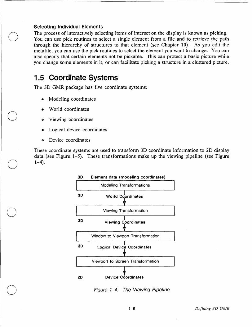
1.5 Coordinate Systems The 3D GMR package has five coordinate systems:
• Modeling coordinates
• World coordinates
• Viewing coordinates
• Logical device coordinates
o Device coordinates
These coordinate systems are used to transform 3D coordinate information to 2D display data (see Figure 1-5). These transformations make up the viewing pipeline (see Figure n 1-4).
~
3D Element data (modeling coordinates)
Modeling Transformations
3D I World C ordinates
o Viewing Transformation
3D Viewing Coordinates
Window to Viewport Transformation
3D Logical Device Coordinates
Viewport to Screen Transformation
20 Device Coordinates
o Figure 1-4. The Viewing Pipeline
1-9 Defining 3D GMR

3D Modeling Coordinates
z
Screen
Display Manager window
Viewport
y
~------+--------x
Figure 1-5. Modeling Coordinates to Screen Coordinates
Defining 3D GMR 1-10
c

o
o
o
o
o
1.5.1 Modeling Coordinates
Primitive elements (graphical objects and text) are defined using modeling coordinates. Conceptually, each structure has its own modeling coordinate system (MCS). This lets you position instanced (sub)structures relative to the parent structure. The relationship between the MCS of a parent structure and the MCS of one of its instanced structures is determined by a transformation that you supply to the instance element in the parent structure.
Given the hierarchy of structures, the MCS of any instance of a structure is related to the MCS of the root instanced from a single (root) structure by a composite modeling transformation. This composite transformation results from composing (e.g., matrix multiplying) all the transformations along the path of the instance elements from the root to the instance in question.
1.5.2 World Coordinates
The modeling coordinate system of the highest level structure displayed in a viewport is especially important. Because of this importance, it is given a special name: the world coordinate system.
By definition, the world coordinate system is a right-handed, three-dimensional Cartesian coordinate system. It may help to think of this coordinate system as having x, y, and z axes with one of two possible orientations:
1. x increasing to the right, y increasing up, and z increasing forwards in the image (see Figure 1-6a).
2. x increasing forwards, y increasing to the right, and z increasing up in the image (see Figure 1-6b).
In both cases, (x X y = z), where X is the vector cross-product.
y z
(a) (b)
Figure 1-6. Examples of Right-handed World Coordinate Systems
1-11 Defining 3D GMR
--_ .. _----_._---- --_.
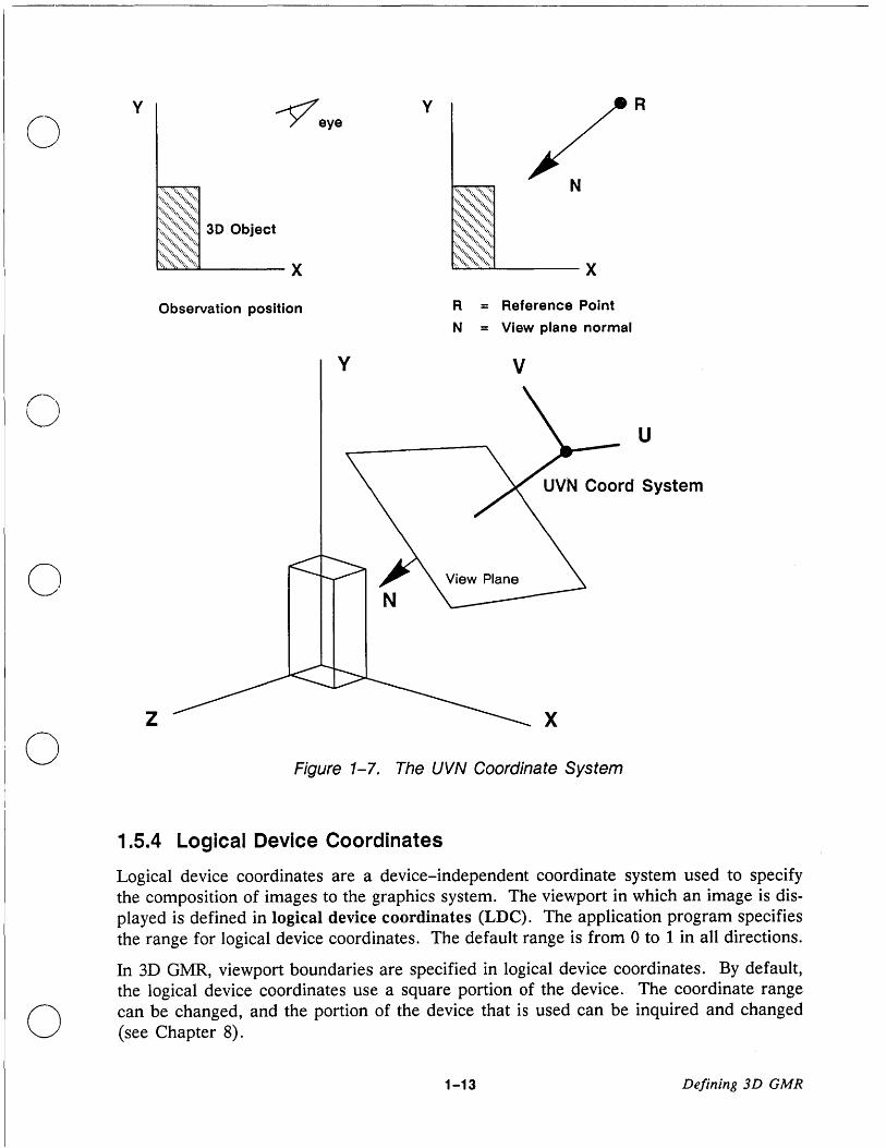
1.5.3 Viewing Coordinates
The viewing coordinate system (also called the UVN system) may be oriented and positioned anywhere in world coordinate space. The UVN system has two main uses:
1. It is used to specify the clipping volume that determines the geometrical portion of the object to be displayed in a view.
2. It defines the view plane that is used to transform 3D world coordinates to 2D logical device coordinates.
Figure 1-7 shows one possible UVN coordinate system. You specify most of the viewing parameters in world coordinates because they control the portion of the world coordinate system to be mapped to the viewport on the screen. For a detailed description of the UVN coordinate system, see Chapter 7.
Defining 3D GMR 1-12
C::
o
o
o
o
y ~eye y R
Observation position R = Reference Point
N = View plane normal
y V
z x
Figure 1-7. The UVN Coordinate System
1.5.4 Logical Device Coordinates
Logical device coordinates are a device-independent coordinate system used to specify the composition of images to the graphics system. The viewport in which an image is displayed is defined in logical device coordinates (LDC). The application program specifies the range for logical device coordinates. The default range is from 0 to 1 in all directions.
In 3D GMR, viewport boundaries are specified in logical device coordinates. By default, the logical device coordinates use a square portion of the device. The coordinate range can be changed, and the portion of the device that is used can be inquired and changed (see Chapter 8).
1-13 Defining 3D GMR

1.5.5 Device Coordinates
Device coordinates are used by the display device. For direct, borrow, and main-bitmap modes, these are bitmap coordinates. The device range is set so that it is within the bitmap for direct, borrow, and main-bitmap mode.
The device coordinate system can usually be ignored by the user, as the 3D GMR package maps to the Display Manager window or screen. In performing this mapping, the 3D GMR package converts the device-independent world coordinates that you specify to device coordinates when it renders the metafile. This allows the same file to be displayed on different types of DOMAIN nodes without requiring changes to your application program. It also allows you to set viewport bounds within the Display Manager window.
This support across devices (device-independence) is based on the separation of coordinate systems built into the 3D GMR package. You can use modeling coordinates to define objects in the three-dimensional world. The 3D GMR package converts these to device coordinates that relate directly to the screen or main-memory bitmap.
1.6 Data Types The 3D GMR package uses single-precision, floating-point coordinate data to provide maximum flexibility and range.
1 .7 Using Color The 3D GMR package allows you to set and change color in two ways:
1. Include color attribute elements in the metafile to establish color for particular modeling elements (polylines, multilines, polygons, polymarkers, meshes, and text).
2. Establish color by using another set of routines at display time (attribute block routines). This allows you to change color without editing the metafile.
The 3D GMR color scheme is designed to give you a flexible combination of automatic and controllable color selection. Color assignments to primitive elements are handled through the attribute elements associated with color identification numbers.
The binding of these color identification numbers to meaningful color definitions is performed at display time. This scheme allows you to respecify a color map allocation to smooth out an image or emphasize an area of interest without editing the metafile.
Defining 3D GMR 1-14
C)
o I
I

o
o
o
o
1.8 3D GMR and Other DOMAIN Graphics Packages The DOMAIN system also has three other graphics packages:
• DOMAIN 2D Graphics Metafile Resource (2D GMR)
• DOMAIN Graphics Primitives (GPR)
• DOMAIN Core Graphics
2D GMR is a standard library on the DOMAIN system. 2D GMR is similar in concept and orientation to 3D GMR.
The graphics primitives library (GPR) is built into your DOMAIN system. The routines (primitives) that make up the library let you manipulate the least divisible graphic elements to develop high-speed graphics operations. These elements include lines and polylines, text with various fonts, and pixel values. For a detailed description of graphics primitives, see Programming with DOMAIN Graphics Primitives and the DOMAIN System Call Reference.
The DOMAIN system also has an optional Core graphics package. The Core graphics 'package provides a high-level graphics environment in which to build portable graphics application systems. For a detailed description of Core graphics, see Programming With DOMAIN Core Graphics.
The distinctive characteristics of the three systems are as follows:
• Graphics Metafiles: The Graphics Metafile Resource includes both 2D and 3D GMR. Picture data is stored in device-independent files. Both packages let you create, edit, display, and store picture data. Storage and rapid redisplay functions are combined into one package. This allows rapid interactive editing and redisplay. Coordinates are device-independent, providing flexibility in the development and use of application programs. See Chapter 13 for a comparison of 2D and 3D GMR.
• Graphics Primitives: The GPR function calls cause changes to be made to a bitmap to create a graphic image. There is no memory of the calls performed except to the limited extent of being able to save a static image at any given time. Storing the bitmap in a file does not save the sequence of graphics commands used to create the image on the bitmap. Therefore, rect'rawing usually requires that an application program itself keep track of and re-execute the calls. GPR display coordinates are device-dependent. See Chapter 13 for information on intermingling GPR and 3D GMR routines.
• Core Graphics: The functions in this package conform to an industry standard. The functions include modeling and viewing capabilities. The Core package stores segments only for redisplay during the same session; no permanent copy is created. These segments cannot contain instances of other segments. Z-coordinates are
1-15 Defining 3D GMR

device-independent, providing flexibility in the development and use of application programs.
/~\
3D GMR is distinct from the graphics primitives (GPR) package in this way: GPR opera- ~j/
tions are performed directly to the output device; 3D GMR operations read, modify, or display a metafile.
c
c' Defining 3D GMR 1-16

~-------.--------------------------------------
o
o
o
o
o
Chapter 2
Controlling 3D Metafiles
This chapter describes the organization of metafiles and the basic procedure for developing programs using 3D GMR. The chapter also presents routines for controlling the 3D GMR package and its files and structures.
2.1 Organization of Metafiles As described in Section 1.2, a metafile is divided into structures that are each a series of elements. The basic organization of a metafile is hierarchical (see Figure 2-1). This top-down organization is fundamental to the efficient use of 3D GMR (see Section 2.3).
2-1 Controlling 3D Meta/iles

structure 1
structure 2 structure 3
structure 4 structure 5
structure 7
structure 6
Figure 2-1. Example of Hierarchical Structure
In Figure 2-1, the main structure directly or indirectly references six other (sub) structures. Structure 1 instances structure 2 four times and structure 3 five times. Structure 2 in turn instances structure 4 and structure 5. Structure 5 instances structure 6 and structure 7. Each structure is created only once in the metafile. Each time a structure is needed, an instance routine (similar to a subroutine call) references it. See Chapter 5 for more information on instancing.
2.1.1 A Programming Analogy
A metafile is analogous to a computer program in many ways, including the following:
• Metafiles are like binary files or executable images
• Structures are like program subroutines
Controlling 3D MetaJiles 2-2

o
o
o
o
o Elements are like CPU instructions
• Tag elements are like comments or debugging information that is put into the executable image
• Instances are like call subroutine instructions
A metafile need not have a single "main structure" as in Figure 2-1. A metafile can have several top-level structures, as shown in Figure 2-2. In this way a metafile is similar to a system library that has several entry points.
A given structure may be instanced more than once by another structure. A structure can also be instanced by more than one structure (see Figure 2-2).
Assembly 1 Assembly 2 ,
subassembly1 I subassembly2 subassembly3
I basic basic basic basic component 1 component 2 component 3 component 4.
Figure 2-2. A Metafile with Two Top-Level Structures.
For example, you may have a structure that represents a screw. Many different parts of the model may use this screw. The system keeps track of the path from the original screw to each instance of it. If you change the original structure, all instanced structures are also changed automatically. Changing the size of all the screws of one type in the model requires changing only the original structure.
Recursive instancing is not supported. There are no conditional flow of control features (for example, if statements) to exit a recursive instancing loop.
2.1.2 Metafile Contents versus Display-Time Parameters
The metafile stores information about the physical objects that are being modeled. This information is stored independently of how the objects are viewed. For example, the following items are stored in the metafile:
2-3 Controlling 3D Metafiles

• Modeling transformations (4x3 matrices) associated with instance elements
• Elements specifying geometric shapes
• Attribute elements specifying, for example, how to color surfaces
The metafile specifies the coordinates of the geometry and many of the parameters used for rendering the image. However, the application can control many details of what is viewed at display time without editing the metafile. The following are some of the display-time features that the application can specify:
• The viewing transformation and the global modeling transformation. Together these transformations determine the position, orientation, and scale of the geometry, as well as the reference point from which it is viewed.
• The colors associated with the color identificatio-n numbers used in the file.
• Attribute blocks that provide a level of indirection in specifying attributes.
NOTE: The application can store viewing information in the metafile by using tags (see Chapter 13).
2.2 Structure of 3D GMR Application Programs The basic procedure for developing a graphics metafile program is as follows:
• Initialize the graphics metafile package, specifying a display mode and bitmap.
• Open or create one or more 3D GMR files.
• To make changes (edit the metafile):
1. Open a structure in a metafile. 2. Move to some location in the structure.
a. Examine the element at that location or
b. Delete the element at that location or
c. Insert a new element at that location or replace it. 2. Close the structure.
Controlling 3D Metafiles 2-4
i"" \ \ ....... '
c

o
C"\ )
o
o
o
• To view the metafile: 1. Create one or more viewports (or use defaults). 2. Establish viewing parameters (or use defaults). 3. Assign a structure to the viewport. 4. Refresh the viewport.
• To edit and view changes interactively, see Chapters 9 and 11.
• To use locator input to select or pick items in the view, see Chapter 10.
o Close the metafile(s).
• Terminate the 3D GMR package.
An application program that uses the routines of the graphics metafile package must first initialize the 3D GMR package. Once the 3D GMR package is initialized, the next step is to create a metafile or to open a previously created one. You must open a file to display or edit it. You can create or edit structures within this open file; you can insert and delete elements within the structures of the open file.
Once you establish a structure, you may edit and redisplay it. Editing a structure is analogous to editing a line of text with an editor. Every element in a metafile is part of some structure, just as every character in a text file is part of some line.
2.3 Structure Hierarchy The following statement emphasizes a fundamental principle of 3D GMR:
Organizing structures in a logical or spatial hierarchy can greatly increase performance.
When you instruct 3D GMR to render a metafile (either for display or picking), it performs a top-down search (called a traversal). By organizing structures in a top-down manner, you greatly increase the efficiency of this search. The search procedure can disregard entire portions or subtrees of the metafile. The following are some of the features that are affected by the hierarchy of structures:
. • Reusing structures by changing transformations (instancing). This decreases the size of the metafile and allows quick updating of repeatedly used objects.
• Viewing all or part of a metafile. For example, if all electrical components of a an assembly are in separate structures, you can turn off all of these components by setting the visibility mask of the appropriate subtrees (see Chapter 9).
• Increasing the speed of refreshing viewports. Clipping is a time consuming part of viewport refreshing. Entire subtrees can become ineligible for clipping.
• Echoing an entire subtree or any portion of it.
2-5 Controlling 3D Metajiles

See Chapter 13 more information.
2.4 Controlling the 3D Graphics Metafile Package Routines:
GMR_$INIT
GMR_$TERMINATE
To use the graphics metafile package, you must initialize it. At the end of a program which uses graphics metafiles, you must terminate the package.
GMR_$INIT initializes the graphics metafile package. Within this routine, you establish the display mode. The choice of mode depends on the purpose of your program and the environment in which you want the program to run. For example, direct mode is desirable if you want the Display Manager environment to be available while this program is running and displaying.
The graphics metafile package does not require that you operate directly on a bitmap. A bitmap (also called a frame buffer) is a data structure used to store values for each point or pixel in a raster. This data structure is a three-dimensional array of bits having height, width, and depth.
With the 3D GMR package, you use the bitmap established when you initialize the package. The characteristics of this bitmap depend upon the initialization mode. The ~ four modes of the graphics metafile package are shown in Table 2-1. -_/
o Controlling 3D Metafiles 2-6

Table 2-1. Four Display Modes
Display Mode Description
Borrow On the full screen, which is temporarily borrowed from the Display Manager.
Direct Within a Display Manager window, which is acquired from the Display Manager.
C) Main-bitmap Using a bitmap allocated in main memory without a display bitmap.
No-bitmap Without a main memory or display bitmap.
o 2.4.1 Borrow Mode
o
o
In borrow mode, the 3D GMR package borrows the full screen and the keyboard from the Display Manager and uses the display driver directly through 3D GMR software. All windows disappear from the screen. The Display Manager continues to run during this time. However, it does not write the output of any other processes to the screen or read any keyboard input until the 3D GMR package is terminated. Input you have typed ahead into input pads can be read by the related processes while the display is borrowed.
Borrow mode has the advantage of using the entire screen. However, because borrow mode takes over the entire display from the Display Manager, other processes are not immediately available.
2.4.2 Direct Mode
Direct mode is similar to borrow mode, but the 3D GMR package borrows a Display Manager window instead of borrowing the entire display. The 3D GMR package acquires control of the display each time it must generate graphics output within the borrowed window. All other processes are handled normally by the Display Manager.
Direct mode offers a graphics application the performance and unrestricted use of display capabilities found in borrow mode. In addition, direct mode permits the application to
2-7 Controlling 3D Metafiles

coexist with other activities on the screen. Direct mode is the preferred mode for most ('\ \,'---.-/' interactive graphics applications.
2.4.3 Main-Bitmap Mode
In main-bitmap mode, the 3D GMR package creates a main memory bitmap, but does not create a display bitmap. To display the file on the screen, you must terminate main-bitmap mode and reinitialize in borrow or direct mode.
This mode allows you to create user-available bitmaps larger than the full display. It is similar to no-display mode in the Graphics Primitives package.
2.4.4 No-Bitmap Mode
No-bitmap mode allows you to build a file without a main memory bitmap or display. No viewing operations may be performed in this mode. To display the file, you must terminate 3D GMR and reinitialize it in borrow or direct mode.
This mode provides the most efficient way to create a metafile from a database when you do not need to be simultaneously monitoring a graphic display of the picture.
2.5 Controlling Files Routines:
GMR_$FILE_CREATE
GMR_$FILE_OPEN
GMR_$FILE_CLOSE
GMR_$FILE_SELECT
After initializing the graphics metafile package, you must create and open a file using GMR_$FILE_CREATE or open an existing file using GMR_$FILE_OPEN. This becomes the current file. Within this file, you create structures into which you insert and store elements.
When you use the routine GMR_$FILE_CREATE, you give the file a pathname and the 3D GMR package assigns an identification number.
To read or edit an existing file, you must open it with GMR_$FILE_OPEN. Upon completion of editing or using a file, you must close it with GMR_$FILE_CLOSE.
You may have more than one file open at a time. When you open a file while another file is open, the newly opened file becomes the current file and the context of the old file is saved.
Controlling 3D Metafiles 2-8
C'I

o
o
o
o
You may switch among open files for editing, viewing, and copying purposes using GMR_$FILE_SELECT. However, you cannot switch to another open file while a structure is open (close the structure first and then use GMR_$FILE_SELECT). When you close the current file, the package is left with no current file; you must then select a file in order to proceed.
You can perform many normal Shell functions on these files. You can copy (cpf), move (mvf) , and delete (dlf) them, but you cannot concatenate (catf) them.
The following routines either require or return a file_id argument:
• GMR_$FILE_CREATE creates a file and returns the file_ide
• GMR_$FILE_OPEN opens an existing file and returns the file_ide
• GMR_FILE_SELECT allows switching between open files for editing, viewing, and copying.
• GMR_$STRUCTURE_COPY copies the contents of one structure into another structure. You can copy either within the current file or (with some limitations) between files. When copying between files, file_id identifies the source file.
• GMR_$VIEWPORT_INQ_STRUCTURE returns the structure_id and the file_id of the structure assigned to a particular viewport for display.
2.6 Controlling Structures Routines:
GMR_$STRUCTURE_CREATE
GMR_$STRUCTURE_OPEN
GMR_$STRUCTURE_INQ_OPEN
GMR_$STRUCTURE_CLOSE
GMR_$STRUCTURE_COPY
GMR_$STRUCTURE_DELETE
GMR_$STRUCTURE_ERASE
GMR_$STRUCTURE_SET_NAME
GMR_$STRUCTURE_INQ_NAME
GMR_$STRUCTURE_INQ_ID
GMR_$STRUCTURE_INQ_COUNT
G~R_$STRUCTURE_INQ_INSTANCES
GMR_$STRUCTURE_INQ_BOUNDS
GMR_$INSTANCE_TRANSFORM_FWD_REF
The elements within a file are grouped into structures. You must open a structure before you can add elements to it.
2-9 Controlling 3D Metafiles

You can create a new structure with GMR_$STRUCTURE_CREATE or GMR_$INSTANCE_TRANSFORM_FWD_REF. The former is the easiest way to create a new structure. The latter allows you to forward reference an as yet undefined structure when inserting an instance element (see Chapter 5).
GMR_$STRUCTURE_OPEN opens an existing structure for redisplay or editing. This structure becomes the current open structure. The element index is set to 0 (see Chapter 11).
GMR_$STRUCTURE_OPEN has a boolean parameter that allows you to specify whether or not to create a back-up version of the structure before opening it (back_up = TRUE creates a back-up version). Use back_up = FALSE whenever appropriate since creating back-up versions takes up free space and can cause the metafile to grow . Use back_up =
TRUE mainly when a structure is going to be opened for a lengthy period of interactive editing that the user may want to retract.
GMR_$STRUCTURE_INQ_OPEN returns the structure identification number of the current open structure.
When you open a structure, the. 3D GMR package automatically assigns a unique identifier, the structure ill. You can optionally give the structure a uinique name using GMR_$STRUCTURE_SET_NAME.
NOTE: Assigning names within metafiles with a large number of structures can become cumbersome because each name must be unique. Each time you create a new name, the current list of names is checked (affecting performance time slightly). Store the structure ill whenever possible to avoid unnecessary calls to inquire the ill.
You can use the structure ill to create instances of the structure within other structures or to view the structure. The identification number (and optional name) of a structure is stored so that it is retained after you terminate the 3D GMR package.
~ ....... -- .. '
c
Nb ote that vibewidn? 0IPeradtions are independent of editing operations. A structure need not C e open to e ISP aye .
GMR_$STRUCTURE_CLOSE closes the current structure. You can specify whether or not you want to save the changes you have made.
GMR_$STRUCTURE_INQ_ID returns the structure identification number of the named structure. Use. GMR_$STRUCTURE_INQ_NAME to retrieve the name of any existing structure in the current file for which you know the identification number; If necessary, use GMR_$STRUCTURE_INQ_OPEN to retrieve the ill of the current open structure.
You may want to name an unnamed structure or rename an already named structure before or during the process of editing it. To do this, use GMR_$STRUCTURE_SET_NAME.
You may set the name of any structure, not just the current structure.
Controlling 3D Metafiles 2-10

o
(J
o
GMR_$STRUCTURE_DELETE deletes the current structure. You must open a structure before you can delete it. If there are any references to (instances of) this structure in other structures of this file, the structure is not deleted.
GMR_$STRUCTURE_COPY copies the entire contents of another structure into the current structure.
GMR_$STRUCTURE_ERASE erases the contents of a structure, leaving an empty structure.
GMR_$STRUCTURE_COPY/ERASE/DELETE are editing functions, which are described in more detail in Chapter 11.
GMR_$STRUCTURE_INQ_COUNT returns the total number of structures in the metafile and a structure number guaranteed to be greater than or equal to the largest structure number. You can then examine every structure by checking structure numbers from 0 to the maximum value.
GMR_$STRUCTURE_INQ_INSTANCES returns the number of instance elements that invoke a particular structure and the maximum number of levels of instancing that occur beneath the structure (see Chapter 5).
GMR_$STRUCTURE_INQ_BOUNDS returns the limits of the bounding box that encloses a structure and any of its subtrees. See Section 13.1 for more information on bounding boxes.
2.7 Structure Characteristics Routines:
GMR_$STRUCTURE_SET_ VALUE_MASK
GMR_$STRUCTURE_INQ_ VALUE_MASK
GMR_$STRUCTURE_SET_TEMPORARY
GMR_$STRUCTURE_INQ_TEMPORARY o Characteristics such as visibility and pickability can be associated with a structure.
o
GMR_$STRUCTURE_SET_ VALUE_MASK assigns a value and mask to a structure. At display-time, the value and mask are compared against viewport filters to specify whether the structure and instanced structures will be visible and/or pickable in that particular viewport (see Figure 2-3).
·2-11 Controlling 3D Metafiles

Structure Viewport Filters c ..lIII Visibility range
Structure mask -~
.... ~ Pick range
..lIII Visibility mask Structure value - -....
~ Pick mask
Figure 2-3. Structure Visibility and Pickability
Using the structure value and mask to set visibility enables you to display a picture without structures that may clutter it. For example, you may want to see a picture with or without text. You can place text in a separate structure and then change the visibility value of that structure to make it visible or invisible. r"'"
"--_.I Using the structure value and mask to set pick eligibility enables you to specify which objects can be selected by an input device. For example, there may be several different objects in one area of the screen, but you can specify that the input device will only identify a certain type of object.
You can also assign visibility and pickability characteristics to the elements within a structure using name set attributes (see Chapter 4).
GMR_$STRUCTURE_INQ_ VALUE_MASK returns the value and mask of the specified structure.
GMR_$STRUCTURE_SET_TEMPORARY sets the current structure as temporary or permanent. A temporary structure is deleted when the file is closed (provided that it is not instanced elsewhere in the file by a permanent structure). A temporary structure is useful for picture data that you want to display but not store. This allows you to add a graphic element, such as an enclosing box or a superimposed grid, which you do not want to store in the metafile.
The following rules apply to temporary structures when you close the file:
1. Temporary structures that are not instanced by other structures are deleted.
2. Temporary structures that are instanced by permanent structures are not deleted.
2. A temporary structures that is instanced by other temporary structures is deleted if all the temporary structures that instance it are deleted.
GMR_$STRUCTURE_INQ_TEMPORARY indicates whether the current structure is set to temporary or permanent.
Controlling 3D Meta/iles 2-12
(' '-- /
c

o
o
o
o
2.8. Displaying Structures Routines:
GMR_$VIEWPORT_SET_STRUCTURE
GMR_$VIEWPORT_INQ_STRUCTURE
GMR_$FILE_SET_PRIMARY_STRUCTURE
GMR_$FILE_INQ_PRIMARY_STRUCTURE
Because of the hierarchical nature of the metafile, displaying a structure also displays all of its subtrees (structures that it instances). This is illustrated in Figure 2-4, a simplified version of the metafile in Figure 2-1. Displaying structure 1 displays all of the structures in the file (unless you selectively turn off visibility using structure values, masks, or name sets). Displaying structure 2 shows structures 2, 4, 5, 6, and 7. Displaying structure 4 eliminates the display of any other structures.
Figure 2-4. Instanced Structures
Structures are not assigned to viewports by default. You must explicitly assign a structure to a viewport using GMR_$VIEWPORT_SET_STRUCTURE.
The concept of a primary structure lets an application earmark one structure as special so that a subsequent display program can find out which structure to assign to a viewport.
GMR_$FILE_SET_PRIMARY_STRUCTURE makes a structure the primary structure of the current open metafile.
GMR_$FILE_INQ_PRIMARY_STRUCTURE returns the structure ID of the primary structure.
GMR_$VIEWPORT_INQ_STRUCTURE returns the structure ID and the file ID of the structure assigned to a particular viewport.
2-13 Controlling 3D Metafiles
NOTE: GMR_$VIEWPORT_SET_STRUCTURE assigns a structure to a viewport. To make the structure visible, clear (optional) and refresh the viewport (see Chapter 9).
2.9 Writing 3D Application Programs In the sections that follow, the steps required to produce a 3D GMR application program are presented with a sample program.
2.9.1 Including Insert Files
To write 3D GMR application programs, you must include two insert files for the language you are using. The first insert file allows you to use system routines:
Insert File
I sys/ins/base. ins. ftn
I sys/ins/base. ins. pas
I sys/ins/base. ins. c
Programming Language
FORTRAN
Pascal
C
The second insert file allows you to use 3D GMR routines:
Insert File
I sys/insl gmr3d. ins. ftn
Isys/ins/gmr3d.ins.pas
Isys/ins/gmr3d.ins.c
Programming Language
FORTRAN
Pascal
C
c
(-~ In addition, you may require other insert files depending on the system utilities you are
using (for example Isys/ins/error.ins ... ). \,~~
2.9.2 Declaring Variables
To use 3D GMR calls, you must declare the variables used as parameters so that they correspond to the data types of the DOMAIN system. For information on data types, see Chapter 1 of the DOMAIN 3D Graphics Metafile Resource Call Reference.
Controlling 3D Meta/iles 2-14

o
o
o
o
2.9.3 Initializing the 3D GMR Package
To execute 3D GMR calls in an application program, you must first initialize the package. To do this, call GMR_$INIT in the application program.
2.9.4 Preparing an Algorithm to Perform a Task
The next step in the development of a 3D GMR application program is to prepare an algorithm using 3D GMR routines to accomplish the task at hand.
2.9.5 Terminating a 3D GMR Session
Use GMR_$TERMINATE to end a 3D GMR session. This routine closes any open files and structures and saves the changes.
2.1 0 Running 3D GMR To use 3D GMR, you must execute an INLIB command for every process in which you want 3D GMR to run. For example:
$ INLIB ILIB/GMR3DLIB
This procedure works on any node. However, performance is improved when you use the version tailored to your node. Section 13.2.3 lists these specially tailored versions.
2.11 A Sample Program This first sample program demonstrates the basic use of the 3D GMR package. The program performs the following operations:
1. Initializes the 3D GMR package in direct mode and opens a metafile named test_gmfile.
2. Creates a structure named object and inserts a 3D box into the structure.
3. Creates a structure named scene and instances the object structure twice within the scene structure. The first instance is rotated around the Y and X axes. The second uses the same rotation plus a scaling factor.
4. Assigns the scene structure to the default viewport and draws it.
2-15 Controlling 3D Metafiles

5. Closes the metafile and exits the 3D GMR package when the user moves the cursor C into the shell input pad and presses RETURN. .-/"
Figure 2-5 shows the output of this first example.
(~ I \ ........ .
Figure 2-5. Example 1
Controlling 3D Metafiles 2-16

o
o
o
o
{*******************************************************************************
* * EXAMPLE_1
*
* * *
********************************************************************************} PROGRAM example_1;
%INCLUDE '/sys/ins/base.ins.pas'; %INCLUDE '/sys/ins/error.ins.pas'; %INCLUDE '/sys/ins/pgm.ins.pas'; %INCLUDE '/sys/ins/gmr3d.ins.pas';
{ Global variables }
VAR status file_id str bitmap_size plane_cnt object_id scene_id mat vpid scale1
status_$t; gmr_$file_id_t; ARRAY [1 .. 100] OF gmr_$i2_point_t := INTEGER := 8; gmr_$structure_id_t; gmr_$structure_id_t; gmr_$4x3_matrix_t; gmr_$viewport_id_t; gmr_$f3_vector_t :=
{ status return variable { The returned file id
CHAR; {Place keeper for ending [1024,1024] ; {The bi tmap size
{ Number of planes to use { The original structure id { The composite structure id { Matrix used for modeling { Viewport id number
0.5, 0.5, 0.5]; {Scaling factor
{******************************************************************************** * * MAKE_OBJECT
* * function:
* Generates a 3D box using polylines and multilines.
*
* * * * * *
} } } } }
} } } }
*********************************************************************************}
PROCEDURE make_object; VAR
pts_front pts_back pts_connect
BEGIN pts_front[l] .x pts_front[l] .y pts_front[l] .z pts_front[2] .x pts_front[2] .y pts_front[2] .z pts_front[3] .x pts_front[3] .y pts_front[3] .z pts_front[4] .x pts_front[4] .y
ARRAY [1 .. 4] of gmr_$f3_point_t; ARRAY [1 .. 4] of gmr_$f3_point_t; ARRAY [1 .. 8] of gmr_$f3_point_t;
.- 0.6;
.- -0.6;
.- 0.0;
.- 0.6;
.- 0.6;
.- 0.0;
.- -0.6;
.- 0.6;
.- 0.0;
.- -0.6;
.- -0.6;
2-17 Controlling 3D Metafiles

pts_front[4] .Z .- 0.0;
GMR_$F3 _POLYLINE ( 4, pts_front, TRUE, status
pts_back[l] .x .- pts_front[l] .x; pts_back[l] .y .- pts_front[l] .y; pts_back[l] .z .- pts_front[l] .z + 0.5; pts_back[2] .x .- pts_front[2] .x; pts_back[2] .y .- pts_front[2] .y; pts_back[2] .z .- pts_front[2] .z + 0.5; pts_back[3] .x .- pts_front[3] .x; pts_back[3] .y .- pts_front[3] .y; pts_back[3] .z .- pts_front[3] .z + 0.5; pts_back[4] .x .- pts_front[4] .x; pts_back[4] .y .- pts_front[4] .y; pts_back[4].z .- pts_front[4].z + 0.5;
GMR_$F3 _POLYLINE ( 4, pts_back, TRUE, status
pts_connect[l] .- pts_front[l] ; pts_connect[2] .- pts_back[l] ; pts_connect[3] .- pts_front[2] ; pts_connect[4] .- pts_back[2] ; pts_connect[5] .- pts_front[3] ; pts_connect[6] .- pts_back[3] ; pts_connect[7] .- pts_front[4] ; pts_connect[8] .- pts_back[4] ;
GMR_$F3_MULTILINE(8, pts_connect, status); END;
) ;
) ;
{*******************************************************************************
* * * CREATE_SCENE
* * function:
* Generates two instances of the box.
* The first instance is rotated around the Y and X axes.
* The second has the same rotation and is also scaled by 0.5.
*
* * * * * * *
********************************************************************************} PROCEDURE create_scene; BEGIN { Get the identity matrix to use as a base matrix. }
{ Build a matrix that rotates and around Y and X axes. }
GMR_$ 4X3_MATRI X_ROTATE (gmr_$mat_post_mult ,gmr_$y_axis , 1 O.O,mat,status); GMR_$4X3_MATRIX_ROTATE(gmr_$mat_post_mult ,gmr_$x_axis , 1 O.O,mat,status);
Controlling 3D MetaJiles 2-18

o
o
o
o
{ Use the matrix to create a rotated box. }
GMR_$INSTANCE_TRANSFORM(object_id,mat,status);
{ Add a scale factor to the matrix. }
GMR_$4X3_MATRIX_SCALE(gmr_$mat_post_mult,scale1,mat,status);
{ Create a second scaled box. }
GMR_$INSTANCE_TRANSFORM(object_id,mat,status);
END;
{*******************************************************************************
* * * MAINLINE
* * *
********************************************************************************} BEGIN
{ Initialize the package and open the file. }
GMR_$INIT(gmr_$direct, stream_$stdout, bitmap_size, plane_cnt, status); GMR_$FILE_CREATE(~test_gmfile', 11, gmr_$overwrite, gmr_$lw, file_id, status);
{ Create an object structure. }
GMR_$STRUCTURE_CREATE ('object', 6, object_id, status); make_object; GMR_$STRUCTURE_CLOSE (TRUE , status);
{ Create a scene containing two instances of the object. }
GMR_$STRUCTURE_CREATE ( 'scene~, 5, scene_id, status); create_scene; GMR_$STRUCTURE_CLOSE (TRUE, status);
{ Connect the scene structure to the default viewport and draw it. } vpid :=.1;
GMR_$VIEWPORT_SET_STRUCTURE ( vpid, scene_id, status ); GMR_$VIEWPORT_CLEAR( vpid, status); GMR_$VIEWPORT_REFRESH( vpid, status );
{ Wait here until carriage return to exit. { Move the cursor into the shell input pad and press RETURN to exit. } readln(str);
{ Clean up and exit. } GMR_$FILE_CLOSE(TRUE, status); GMR_$TERMINATE(status);
END.
2-19 Controlling 3D Metajiles

c
\,-....
c

o
o
o
o
Chapter 3
Using Drawing Primitives
This chapter describes the modeling routines that insert single primitive elements into the current open structure of the metafile. The 3D GMR package reads these elements in the course of displaying a file, causing something to be drawn. The primitive elements include polylines (connected line segments), multilines (disconnected line segments), polygons, polymarkers, meshes, and text. Generally, one primitive element is inserted into the metafile each time one of these primitive routines is called. Each routine has a complementary inquire routine that returns the values of a single primitive element.
Routines:
GMR_$F3_POL YLINE
GMR_$F3_POL YGON
GMR_$F3_POL YMARKER
GMR_$F3_MESH
GMR_$F3_MULTILINE
GMR_$TEXT
GMR_$INQ_F3_POLYLINE
GMR_$INQ_F3_POL YGON
GMR_$INQ_F3_POLYMARKER
GMR_$INQ_F3_MESH
GMR _ $ INQ_ F3 _MUL TILINE
GMR_$INQ_TEXT
3-1 Using Drawing Primitives

3.1 Polylines GMR_$F3_POL YLINE inserts a primitive element into the current structure that draws a 3D polyline (list of linked line segments). In using this routine, you specify a vertex count and an array of 3D floating-point coordinates. GMR_$INQ_F3_POL YLINE returns the parameters of an existing polyline. Line type is controlled by the current line type identification number set for polylines and multilines. To specify line type, use GMR_$LINE_TYPE (see Chapter 4).
Use GMR_$ABLOCK_SET_LINE_TYPE to set the line type for an attribute block (see Chapter 6).
Color selection is controlled by the current color identification number and intensity value for polylines and multilines. To specify color and intensity, use GMR_$LINE_COLOR and GMR_$LINE_INTEN (see Chapters 4 and 12).
Use GMR_$ABLOCK_SET_LINE_COLOR and GMR_$ABLOCK_SET_LINE_INTEN to set the line color and intensity for an attribute block (see Chapter 6).
3.2 Multilines GMR_$F3_MULTILINE inserts a primitive element into the current structure that draws a 3D multiline. A multiline element draws a sequence of unconnected line segments (a polyline draws connected line segments). In using this routine, you specify a vertex count and an array of 3D floating-point coordinates. The number of points must be even. GMR_$INQ_F3_MULTILINE returns the parameters of an existing multiline element. Line type, color, and intensity selection is identical to polylines (see above).
3.3 Polygons GMR_$F3_POL YGON inserts a primitive element into the current structure that draws a 3D polygon. In using this routine, you specify a vertex count and an array of 3D floating point coordinates. GMR_$INQ_F3_POL YGON returns the parameters of an existing polyline. Color selection is controlled by the current color identification number and intensity value for polygons. To specify fill color and intensity, use GMR_$FILL_COLOR
and GMR_$FILL_INTEN (see Chapters 4 and 12).
Use GMR_$ABLOCK_SET_FILL_COLOR and GMR_$ABLOCK_SET_FILL_INTEN to set the fill color and intensity for an attribute block (see Chapter 6).
Using Drawing Primitives 3-2
C" _/
\. ...... -...
o

o
o
C)
0
0
3.4 Polymarkers GMR_$F3_POLYMARKER inserts a primitive element into the current structure that draws a set of markers. A marker is used to graphically identify a location in modeling coordinate space. For example, you can use markers to represent the data points on a graph.
3D GMR currently supports five types of markers as shown in Table 3-1.
Table 3-1. Mark~r Types
Type ID Marker
1 • (single pixel)
2 + 3 4-4 0
5 X
The default is marker type 1 (single pixel).
You can set the following marker characteristics (see Chapter 4):
Characteristic Routines
type GMR_$MARK_TYPE and GMR_$ABLOCK_SET_MARK_TYPE
size GMR_$MARK_SCALE and GMR_$ABLOCK_SET_MARK_SCALE
color GMR_$MARK_COLOR and GMR_$ABLOCK_SET_MARK_COLOR
intensity GMR_$MARK_INTEN and GMR_$ABLOCK_SET_MARK_INTEN
3-3 Using Drawing Primitives

GMR_$INQ_F3_POL YMARKER returns the number of markers in a polymarker element, and C: the location of each marker in modeling coordinates.
The position of the marker is mapped from modeling coordinates to device coordinates. However, the marker itself is not affected by any transformation. This means that if you rotate the view, the marker may change position on the screen but it will not appear rotated or skewed.
3.5 Mesh GMR_$F3_MESH inserts a primitive element into the current structure that draws a mesh. To create a mesh, you must supply all of the points that make up the patch corners of the mesh. You can think of the mesh as a two-dimensional array with rows and columns stored in row-major form (see Figure 3-1). This corresponds to the way the data is stored. Specify the number of rows of points, the number of columns of points, and give an array of 3D floating-point coordinates that contains all of the points.
For example, the mesh illustrated in Figure 3-1 has 6 rows of 5 columns, and requires an array of 30 points.
Rows (major dimension)
(1,1)
(2,1)
Columns (minor dimension)
(1,2) (1,3)
(2,2)
(6,3)
(1,4) (1,5)
(6,4) (6,5)
Figure 3-1. A Mesh with 5x4 Quadrilaterals Requires 30 Points
Using Drawing Primitives 3-4

C)
o
o
o
A Note to FORTRAN Users Both C and Pascal store the points of the array in row-major form; that is, element (1,1), (1,2), ... (1,n), (2,1), ... where n is the number of columns. The major dimension is the row, the minor dimension is the column.
FORTRAN stores arrays in column-major form; that is, (1,1), (2,1) ... (m,1), (1,2), ... , where m is the number of rows. To use the mesh call from FORTRAN, the major dimension must be the number of columns and the minor dimension must be the number of rows.
Table 3-2 shows a point array in C, FORTRAN, and Pascal.
GMR_$INQ_F3_MESH returns the parameters of an existing mesh. To specify fill color and intensity use GMR_$FILL_COLOR and GMR_$FILL_INTEN (see Chapters 4 and 12). To set the color and intensity for an attribute block, use GMR_$ABLOCK_SET_FILL_COLOR and GMR_$ABLOCK_SET_FILL_INTEN (see Chapter 6).
The rendering of a mesh is improved if the individual quadrilaterals are approximately planar.
Table 3-2. Point Array in C, FORTRAN, and Pascal
Programming Language Syntax
C GMR_$F3 _POINT my_array [M] [N]
FORTRAN REAL MY ARRAY - (N) (M) (3)
Pascal
my_ array ARRAY [ 1 .. M ] [ 1 .. N ] of GMR_$F3 POINT T -
3.6 Text GMR_$TEXT inserts a primitive element into the current structure that positions and draws a text string. The routine expects a string length, a string, and a 3D floating-point triplet representing the text's location in modeling space. Note that text position is specified in modeling coordinates, but text height is specified in viewing coordinates (same as world coordinates). GMR_$INQ_TEXT returns the parameters of the current (GMR_$TEXT)
element.
3-5 Using Drawing Primitives

You can specify the color, height, slant, spacing, and orientation of text using the text attribute routines described in Chapters 4 and 6.
The first character of the text string is placed at the location you specify called the anchor point. The path direction determines where the anchor lies (see Figure 3-2). Path direction is an attribute set by GMR_$TEXT_PATH (see Chapter 4).
right left down up
t Figure 3-2. Anchor Point and Text Path
You can control text clipping at display time. You can choose whether to clip an entire text string at display time if its anchor point is outside of the viewport. This is the default method and is the fastest way to clip text. You can turn the mode on and off using GMR_$TEXT_SET_ANCHOR_CLIP.
Clipping by anchor point (default) will not display portions of text that are inside the viewport if the text anchor point is outside the viewport. GMR_$TEXT_SET_ANCHOR_CLIP
is a display routine and is described in Section 9.7.
3.7 Examples Using Polylines and Mesh The following two program fragments each create a cone. The first uses polylines and the second uses a mesh.
{**************************************************************************** * * * CONE1: Constructs a cone using polylines.
* * *
****************************************************************************}
PROCEDURE wire_cOne(IN detail: INTEGER);
CONST
VAR
n max 21; PI 3.1415927;
n , i I j
P, q
theta
INTEGER; ARRAY [ 1 REAL;
Using Drawing Primitives 3-6
( '- /

o BEGIN
o
o
o
o
x, y, z r
REAL; REAL; REAL;
IF detail < n_max THEN n .- detail ELSE n .- n_max - 1; d_theta := 2.0 * PI / n;
IF detail <= 1 THEN BEGIN p[1] .x .- 0.0; p[1] .y .- 0.0; p[1] .Z .- 0.0; p[2] .x .- 0.0; p [2] . y .- 0.0; p[2].z .- 1.0; gmr_$f3-polyline(2, p, FALSE, status); check; RETURN END;
FOR i := 1 TO n DO BEGIN theta := i * d_theta; p[i].x .- COS(theta); p[i].y .- SIN(theta); END; p[n+1] .- p[l];
FOR i := 1 TO n DO BEGIN r := i / ( 1.0 * detail ); FOR j := 1 TO n + 1 DO BEGIN q[j].x .- r * prj] .x; q[j].y .- r * p[j] .y; q[j].z .- 1.0 - r;
END; gmr_$f3_polyline(n+1, q, FALSE, status); check; END;
q[l].x .- 0.0; q[l].y .- 0.0; q[l].z .- 1.0; q[2].z .- 0.0; FOR i := 1 TO n DO BEGIN q[2].x := p[i] .x; q[2].y := p[i] .y; gmr_$f3_polyline(2, q, FALSE, status); check; END;
END; {wire_cone }
3-7 Using Drawing Primitives

{**************************************************************************** * * * CONE2: Constructs a cone of unit radius and unit height using a mesh, * * * ****************************************************************************} PROCEDURE cone( IN n : INTEGER );
VAR
BEGIN
i, j, k
mesh c, s
INTEGER; ARRAY [ 1 " 400 ] OF gmr_$f3_vector_t; REAL;
IF ( n <= 1 ) OR ( n >= 20 ) THEN RETURN; k ,- 0; FOR i ,-
BEGIN c := COS( s ,- SIN( FOR j ,-
BEGIN k ,- k + mesh[k] ,x
mesh[k] ,y
mesh[k] ,Z
END; END;
I TO
2 * 2 *
I TO
I' , ,-
,-
,-
n + 1 DO
i * PI / n ) ; i * PI / n ) ;
n DO
c * j / n ) ;
s * j / n ) ; I j / n ) ;
gmr_$f3 mesh( n + I, n, mesh, status ); END; { cone}
Using Drawing Primitives 3-8
c
c
c:'

o
o
o
o
o
Chapter 4
Using Direct Attributes
A metafile can contain attribute elements that change individual characteristics such as line type (for example, solid or dashed), color, and the size and orientation of text.
For each attribute element, there is a routine that inserts the element and a routine that retrieves the parameters of an existing attribute element. For example:
GMR_$LINE_COLOR Inserts an attribute element into the current open structure. This element sets the color of polylines and multilines.
GMR_$INQ_LINE_COLOR Returns the color identification number specified by a GMR_$LINE_COLOR attribute element.
Attribute elements such as GMR_$LINE_COLOR are placed in the metafile. Inquire routines such as GMR_$INQ_LINE_COLOR are used when editing the metafile to retrieve the values set by a particular attribute element (see Chapter 11).
There are two ways to set attributes: direct and aclass. You specify which method is in effect for a particular attribute type using an attribute source flag. These terms are defined below:
direct attribute element An attribute element that affects one particular attribute characteristic. For example, GMR_$LINE_COLOR controls only the color of polylines and multilines. By inserting that attribute element in a particular place in the metafile, you can directly change the way that lines are drawn.
4-1 Using Direct Attributes

aclass element An attribute class element. One of a set of attributes called an attribute block. You first set up an attribute block made up of individual attribute elements. Then you insert aclass 01 elements in the metafile that point to the attribute block. ~'
attribute source flag An attribute source flag is an element inserted in the metafile that specifies whether the current value of the direct or aclass attribute is in effect for subsequently rendered primitives. The default is direct for all attribute types.
Direct attributes are described in this chapter. Aclass attributes and attribute source flags are described in Chapter 6.
4.1 Attributes and Structure Hierarchy For this discussion, assume that all default attribute source flags are set and that only direct attribute elements are encountered. Refer to Chapter 6 for a discussion of how to switch between direct and aclass attributes.
At display time, 3D GMR traverses the metafile and renders (draws) structures according to the current attributes in effect. When 3D GMR encounters a direct attribute element, 'the next structure is displayed with the new attribute value. This new attribute value also applies to the structures subsequently instanced from this structure, but never to the structure which instanced this structure.
For example, assume that the structures in Figure 4-1 are rendered in their numbered order and that structure 1 uses the default line color. Structure 2 is drawn blue and structures 3, 4, and 5 are green. Structure 6 is drawn blue and structures 7 and 8 use the default line color (red).
set line color blue
set line color green
Figure 4-1. Attributes and Instancing
Using Direct Attributes 4-2
~. \

o
C)
o
o
Attributes are like local variables in a programming environment: when you return from executing an instance routine, you revert to the attribute values in effect at the time the instance was invoked. This means that the scope of an attribute element (the part of the metafile affected by the element) is the remainder of the structure in which the element occurs and any structures instanced from that remainder.
The default attribute settings are shown in Table 4-1.
Table 4-1. Default Attribute Settings
Attribute Default Setting
Current name set All elements are members
Fill color ill 1
Fill intensity 1.0
Line type ill 1 (solid)
Line color ill 1
Line intensity 1.0
Marker color ill 1
Marker intensity 1.0
Marker scale factor 1.0
Marker type 1 (one pixel)
Text color ill 1
Text expansion 1.0
Text height 0.01
Text intensity 1.0
Text path angle o radians
Text spacing 0.0
Text slant 0.0
Text up vector (0.0, 1.0)
4-3 Using Direct Attributes

4.2 Direct Attribute Elements The following sections describe direct attribute elements. Chapter 6 explains how to create and use attribute blocks.
4.2.1 Line Types
Routines:
GMR_$LINE_TYPE GMR_$INQ_LINE_TYPE
You can set the line type ill for subsequently rendered polylines and multilines. Currently, four line types are supported:
1 = solid
2 = dashed
3 = dotted
4 = dashed-dotted
GMR_$LINE_TYPE inserts an attribute element into the current open structure. This
CI
element sets the line type ill (1 through 4) for polylines and multilines. (~ GMR_$INQ_LINE_TYPE returns the line type ill of the current (GMR_$LINE_TYPE) element. \,.'
Line types are particularly useful for echoing user-selected objects on a monochrome . node (see Chapter 9).
Use GMR_$ABLOCK_SET_LINE_TYPE to set the line type ill for an attribute block (see Chapter 6).
4.2.2 Basic Color Attributes
Routines:
GMR_$FILL_COLOR GMR_$LINE_COLOR GMR_$MARK_COLOR GMR_$TEXT_COLOR GMR_$INQ_FILL_COLOR GMR_$INQ_LINE_COLOR GMR_$INQ_MARK_COLOR GMR_$INQ_TEXT_COLOR
This section describes the basic use of color. Chapter 12 describes more advanced color features.
Using Direct Attributes 4-4
c'

o
o
o
o
o
Using a Default Color ID To create a primitive element of a certain color, insert the corresponding color attribute element before the primitive element in the metafile. This becomes the color for subsequently rendered primitives of that type. To change color again, insert another attribute element.
The following routines each insert an attribute element into the current open structure. The element sets the color identification number for the specified primitive elements. This color ill becomes the current color for the particular class of primitive. The GMR_$INQ_ ... _COLOR routines return the value of the current (GMR_$ ... _COLOR) element.
polygons and meshes
polylines and multilines
polymarkers
text
GMR_$FILL_COLOR and GMR_$INQ_FILL_COLOR
GMR_$LINE_COLOR and GMR_$INQ_LINE_COLOR
GMR_$MARK_COLOR and GMR_$INQ_MARK_COLOR
GMR_$TEXT_COLOR and GMR_$INQ_TEXT_COLOR
To use the basic color feature, use GMR_$FILL_COLOR, GMR_$LINE_COLOR,
GMR_$MARK_COLOR, or GMR_$TEXT_COLOR and specify a color ill. Table 4-2 shows the default colors that are available for color nodes. Table 4-3 shows the colors for monochrome nodes.
The color ill maps to the color map index. This index maps to colors defined by the default color map. Chapter 12 describes how to change these mappings.
Chapter 12 also describes color intensity. Direct attribute color intensity is established and retrieved by the following routines:
GMR_$FILL_INTEN GMR_$LINE_INTEN GMR_$MARK_INTEN GMR_$TEXT_INTEN GMR_$INQ_FILL_INTEN GMR_$INQ_LINE_INTEN GMR_$INQ_MARK_INTEN GMR_$INQ_TEXT_INTEN
4-5 Using Direct Attributes

Table 4-2. Default Colors for Color Nodes
C) j
Color ID Default Color Map Index Default Color
0 0 black
1 1 red
2 2 green
3 3 blue
4 4 cyan
5 5 yellow
6 6 magenta
7 7 white
8 - 15 8 - 15 Colors used by the Display Manager
16 - 255 7 white
Four-plane color displays have only the first sixteen color map entries.
Table 4-3. Default Colors for Monochrome Nodes
Color ID Default Color Map Index Default Color
0 0 black
1 1 white
2 - 255 1 white
. Using Direct Attributes 4-6

o
o
o
o
o
4.2.3 Polymarker Attributes
Routines:
GMR_$MARK_COLOR GMR_$MARK_INTEN GMR_$MARK_TYPE GMR_$MARK_SCALE GMR_$INQ_MARK_COLOR GMR_$INQ_MARK_INTEN GMR_$INQ_MARK_TYPE GMR_$INQ_MARK_SCALE
Marker attributes allow you to set the color, intensity, type, and size of markers.
GMR_$MARK_COLOR inserts an attribute element into the current open structure. This element sets the color ID for polymarker elements. GMR_$INQ_MARK_COLOR returns the value of the current (GMR_$MARK_COLOR) element.
GMR_$MARK_INTEN inserts an attribute element into the current open structure. This element sets the intensity of color for polymarker elements. Color intensity is described in Chapter 12. GMR_$INQ_MARK_INTEN returns the value of the current (GMR_$MARK_INTEN) element.
GMR_$MARK_TYPE inserts an attribute element into the current open structure. This element establishes the type of markers that are drawn. 3D GMR currently supports five types of markers (see Table 4-4).
Table 4-4. Marker Types
Type ID Marker
1 • (single pixel)
2 + 3 -* 4 0
5 X
The default is type 1 (one pixel).
4-7 Using Direct Attributes

GMR_$INQ_MARK_TYPE returns the value of the current (GMR_$MARK_TYPE) element.
GMR_$MARK_SCALE specifies the scale factor used for markers. To visualize the scale factor, consider the marker in its own coordinate system with the marker's center at the origin. Scale multiplies each coordinate that defines the marker by the scale factor and truncates the result to an integer. For example, Figure 4-2 uses a scale factor of 1.5.
(0,7)
(0,3) (-4,4) (4,4)
(-3,3) (3,3)
(-5,0) --~~-- (5,0) (-7,0)
(7,0)
(-3,-3) (3,-3)
(0,-5) (-4,-4) (4,-4)
(0,-7)
Scale 1 Scale 1.5
Figure 4-2. Polymarker Scale 1.5
The default scale factor is 1. Values less than 1 are ignored and result in a scale factor of 1. Scaling has no effect on marker type 1 (one pixel). GMR_$INQ_MARK_SCALE returns the value of the current (GMR_$MARK_SCALE) element.
4.2.4 Text Attributes
Routines:
GMR_$TEXT_COLOR GMR_$TEXT_EXPANSION GMR_$TEXT_HEIGHT GMR_$TEXT_INTEN GMR_$TEXT_PATH GMR_$TEXT_SLANT GMR_$TEXT_SPACING GMR_$TEXT_VP GMR_$INQ_TEXT_COLOR GMR_$INQ_TEXT_EXPANSION GMR_$INQ_TEXT_HEIGHT GMR_$INQ_TEXT_INTEN GMR_$INQ_TEXT_PATH GMR_$INQ_TEXT_SLANT GMR_$ INQ_TEXT_S PACING GMR_$INQ_TEXT_VP
Using Direct Attributes 4-8

o
o
o
C)
Text attributes allow you to control the rendering of text without display-time interpretation.
GMR_$TEXT_COLOR inserts an attribute element into the current open structure. This element sets the color ill used for rendering text. GMR_$INQ_TEXT_COLOR returns the value of the current (GMR_$TEXT_COLOR) element.
GMR_$TEXT_INTEN inserts an attribute element into the current open structure. This element sets the intensity of color for text. Color intensity is described in Chapter 12. GMR_$INQ_TEXT_INTEN returns the value of the current (GMR_$TEXT_INTEN) element.
GMR_$TEXT_EXPANSION inserts an attribute element into the current open structure. This element sets the ratio of width to height for text, as different from the font. GMR_$INQ_TEXT_EXPANSION returns the value of the current (GMR_$TEXT_EXPANSION)
element.
GMR_$TEXT_HEIGHT inserts an attribute element into the current open structure. This element sets the text height in viewing coordinates (same as world). GMR_$INQ_TEXT_HEIGHT returns the value of the current (GMR_$TEXT_HEIGHT) element.
GMR_$TEXT_PATH inserts an attribute element into the current open structure. This element sets the direction in which text is written. The angle is in radians measured counter-clockwise. GMR_$INQ_TEXT_PATH returns the value of the current (GMR_$TEXT_PATH) element.
GMR_$TEXT_SLANT inserts an attribute element into the current open structure. This element sets the slant of text. A negative value produces a left slant. A positive value produces a left slant. Zero is the default; greater than zero (for example, 0.5) yields an italics-like character. GMR_$INQ_TEXT_SLANT returns the value of the current (GMR_$TEXT_SLANT) element.
GMR_$TEXT_SPACING inserts an attribute element into the current open structure. This element sets the spacing between text characters. Spacing is defined as a fraction of text height. For more spacing between characters, make the spacing value positive. To make characters appear to overlay, make the value negative. GMR_$INQ_TEXT_SPACING returns the value of the current (GMR_$TEXT_SPACING) element.
GMR_$TEXT_VP inserts an attribute element into the current open structure. This element specifies the up direction of text, in the viewing coordinate system (same as world coordinates). Text is oriented on the projection plane. GMR_$INQ_TEXT_VP returns the value of the current (GMR_$TEXT_VP) element.
4.2.5 Name Sets
Routines:
GMR_$ADD_NAME_SET GMR_$REMOVE_NAME_SET GMR_$INQ_ADD_NAME_SET o GMR_$INQ_REMOVE_NAME_SET
4-9 Using Direct Attributes

The visibility and pick eligibility of primitives within visible structures can be controlled using name set attributes. Name sets allow you to classify objects by name. The current name set is an attribute applicable to all primitives. At display time, the names in the current name set are compared to the viewport's invisibility and pick filters (see Figure 4-3). Each filter consists of an inclusion set and an exclusion set that determines which primitives are eligible for the operation.
GMR_$ADD_NAME_SET inserts an element into the metafile that adds names to the current name set attribute, creating a new current name set.
GMR_$INQ_ADD_NAME_SET returns the names in the current (GMR_$ADD_NAME_SET)
element.
GMR_$REMOVE_NAME_SET removes names from the current name set attribute, creating a new current name set.
GMR_$INQ_REMOVE_NAME_SET returns the list of names in the current (GMR_$REMOVE_NAME_SET) element.
The current name set is compared to invisibility and pick filters that are associated with each viewport. Section 9.4.4 describes viewport visibility filters. Section 10.4.2 describes viewport pick filters.
VIEWPORT
Invisibility Filter
Inclusion Set
Exclusion Set PRIMITIVE
Name Set
Pick Filter
Inclusion Set
Exclusion Set
Figure 4-3. Name Sets and Viewport Filters
GMR_$VIEWPORT_SET_INVIS_FILTER specifies which name sets will be invisible for a particular viewport by specifying an inclusion set and an exclusion set.
GMR_$VIEWPORT_INQ_INVIS_FILTER returns the invisibility filters for a specified viewport.
GMR_$VIEWPORT_SET_PICK_FILTER specifies which name sets will be pickable for a particular viewport by specifying an inclusion set and an exclusion set.
Using Direct Attributes 4-10
o
(~' ,--~"
(=~

o
0
0
o
o
GMR_$VIEWPORT_INQ_PICK_FILTER returns the inclusion and exclusion name set lists used to determine picking eligibility in a specified viewport.
4.3 A Program Using Text Attributes This sample program creates text using several of the atttributes described in this chapter. Figure 4-4 shows the output.
~~\\\\\ SLANT SLANT
PACING SPACING SPACING
HEIGHT
HEIGHT
HEIGHT
~ c70 ~C0 ~o ~C0
~~~ ~V «c y /0
~ ~
TEXT
Figure 4-4. Sample Text Output
4-11 Using Direct Attributes

program test_text; { Overview: Creates text and draws it. }
{ insert files } %include '/sys/ins/base.ins.pas'; %include '/sys/ins/error.ins.pas'; %include '/sys/ins/pfm.ins.pas'; %include '/sys/ins/gmr3d.ins.pas';
{ Constant variables } CONST
sin45 = 0.707106781; cos45 = sin45; pi 3.1415926535;
text_s height_s spacing_s slant_s path_s upvector_s
{ Global variables } VAR
4' , 6;
7;
5 ; 4;
8 ;
loc gmr_ $f3 _point_t; text_Ioc height_Ioc spacing_Ioc slant_Ioc path_Ioc upvector_loc
gmr_ $f3 _point_t .- [0.0, 0.0, 0.0] ;
text_t height_t spacing_t slant_t path_t upvector_t
gmr_ $f3 _point_t .- [0.7, -0.3, 0.0] ; gmr_ $f3 _point_t .- [0.7, 0.2, 0.0] ; gmr_ $f3 _point_t .- [0.7, 0.7, 0.0] ; gmr_$f3yoint_t .- [-0.5, -0.5, 0.0] ; gmr_ $f3 _point_t .- [-0.5, 0.5, 0.0] ;
array [1 .. text_s of char .-array [1 .. height_s of char .-array [1 .. spac ing_s of char .-array [1 .. slant_s of char .-array [1 .. path_s of char .-array [1 .. upvector_s] of char .-
array [1 .. 5] of gmr_$text_up_t .- [
[ cos45, sin45 [ -cos45, sin45 [ -cos45, -sin45 [ cos45, -sin45
'TEXT' ; 'HEIGHT'; 'SPACING'; 'SLANT'; ' PATH' ; 'UPVECTOR';
{ 45 {135 {225 {315
[ gmr_$text_up_x_def, gmr_$text_up_y_def ]
] ;
degrees degrees degrees degrees
status str bitmap_size plane_cnt
status_$t; ARRAY [1 .. 100] OF CHAR; gmr_$i2_point_t.- [1024,1024]; INTEGER := 8;
{ Status return variable } { Place keeper for ending } { The bitmap size } { Number of planes to use }
Using Direct Attributes 4-12
--------_._--_._---_._--
c
c'
c'

0
C)
o
o
o
char_name_cnt: INTEGER; { Number of chars in a string } file - id gmr_ $file _id_t; { The returned file ID } text - id gmr_$structure_id_t; { The id for the text structure } vpid gmr_$viewport_id_t; { Default viewport ID } text_normal gmr_ $f3 - vector - t .- [0.0, 0.0, -1.0] ; { View normal vector }
{* * * * * * * * * PROCEDURE check;
* * * * * * * * * * * * * * * * * * * * * * * * * * * * * * }
{ function: checks the status and exits if an error occurs } BEGIN
END;
IF (status. all <> gmr_$operation_ok) THEN BEGIN
writeln( 'status in module example:' status.all); pfm_$error_trap( status );
END;
{* * * * * * * * * * * * * * * * * * * * * * * * * * * * * * * * * * * * * * * } PROCEDURE create_text_structure; VAR
height a expansion_a spacing_a slant_a path_a
i : integer;
gmr_$text_height_t; gmr_$text_expansion_t; gmr_$text_spacing_t; gmr_$text_slant_t; gmr_$text_path_t;
BEGIN height_a := gmr_$text_height_def + 0.1;
gmr_$text_height(height_a,status); check; gmr_$text(text_t,text_s,text_loc,status); check; {text}
height_a := gmr_$text_height_def + 0.05; loc := height_Ioc; FOR i := 1 TO 3 DO
BEGIN gmr_$text_height(height_a,status); check; gmr_$text(height_t,height_s,loc,status); check; {height} height_a := height_a + 0.025; loc.y := loc.y - (height_a +0.1); END; { FOR}
spacing_a := gmr_$text_spacing_def - 0.2; loc := spacing_Ioc; FOR i := 1 TO 3 DO
BEGIN gmr_$text_spacing(spacing_a,status); check;
4-13 Using Direct Attributes

END;
gmr_$text(spacing_t,spacing_s,loc,status); check; { spacing} spacing_a := spacing_a + 0.2; loc.y := loc.y - 0.07; END; { FOR}
slant_a := -0.5; loc := slant_Ioc; FOR i := 1 TO 3 DO BEGIN
gmr_$text_slant(slant_a,status); check; gmr_$text(slant_t,slant_s,loc,status); check; slant_a := slant_a + 0.5; loc.y := loc.y - 0.07; END; { FOR}
path_a : = pi/4. 0;, loc := path_Ioc; FOR i := 1 TO 4 DO BEGIN
gmr_$text_path(path_a,status); check; gmr_$text(path_t,path_s,loc,status); check; path_a := path_a + pi/2.0; END; { FOR}
loc := upvector_loc; FOR i := 1 TO 4 DO BEGIN
gmr_$text_up (upvector_a [i] ,status); check; gmr_$text(upvector_t,upvector_s,loc,status); check; END; { FOR}
gmr_$text_up (upvector_a [5] ,status); check;
{* * * * * * * * * * * * * * * * * * * * * * * * * * * * * * * * * * * * * }
PROCEDURE draw_view ( IN struc_id
IN vpid gmr_$structure_id_t; gmr_$viewport_id_t
) ;
{ function: draw a structure in a viewport} BEGIN
gmr_$viewport_set_structure ( vpid, struc_id, status ); check; gmr_$viewport_clear( vpid, status); check; gmr_$viewport_refresh( vpid, status ); check;
Using Direct Attributes 4-14

o
o
o
o
END; { PROCEDURE
{* * * * * * * * * * * * * * * * * * * * * * * * * * * * * * * * * * * * * * }
BEGIN { Initialize the package and try to open the file. }
gmr_$init ( gmr_$direct, stream_$stdout, bitmap_size, plane_cnt, status ); check;
char_name_cnt := 11;
'text_gmfile', char_name_cnt, gmr_$overwrite, gmr_$lw, file_id, status ); check;
{ Set view plane normal. } gmr_$view_set_view_plane_normal(l, text_normal, status); check;
END.
{ create a text structure } char_name_cnt := 4; gmr_$structure_create ( 'text', char_name_cnt, text id, status); check; create_text_structure; gmr_$structure_close (TRUE, status); check;
{ Connect the structure to the default viewport and draw it } vpid := 1; draw_view(text_id,vpid);
{ wait here until carriage return} readln(str);
{ clean up and exit} gmr_$file_close ( TRUE, status ); check; gmr_$terminate ( status ); check;
4-15 Using Direct Attributes

c
I
I
C

o
o
o
o
o
Chapter 5
Using Modeling Routines
Instancing is an essential part of the structure hierarchy. This chapter describes how instancing affects attributes and uses transformation matrices. Examples include techniques for building transformation matrices and modeling objects using instancing.
5.1 Instancing Routines:
GMR_$INSTANCE_TRANSFORM GMR_$INQ_INSTANCE_TRANSFORM GMR_$INSTANCE_TRANSFORM_FWD_REF GMR_$STRUCTURE_INQ_INSTANCES
Instancing provides an economical and efficient way to reuse structures. You can create a structure once in a metafile and reference it any number of times at different points in the metafile. Each new reference includes a transformation matrix that defines how the copy is to be translated, rotated, and/or scaled to the new location. In programming terms, instancing a structure is analogous to calling a subroutine. Figure 5-1 illustrates a box that is translated, rotated, and scaled via a modeling matrix that is supplied in an instance routine.
5-1 Using Modeling Routines

y y Instanced Structure
Original Structure ~
x x
z z
Figure 5-1. Combined Rotation, Translation, and Scaling
The following rules apply to instancing:
• A structure must exist before you can instance it.
• You must open a structure to edit it. Opening a structure does not open the structures that are instanced.
• A structure may contain instances of other structures with one restriction: instancing cannot be circular (recursive) since there are no flow of control features (for example, if statements) to exit a recursive loop. In particular, a structure may not instance itself.
• A structure can contain multiple instances of the same structure, with different attributes and transformation matrices. Interspersing instance elements and attribute elements makes it possible to display different instances with different attributes.
GMR_$INSTANCE_TRANSFORM inserts an instance element into the current open structure. An instance element contains a reference to another structure of the metafile and a modeling 4x3 transformation matrix.
GMR_$INSTANCE_TRANSFORM_FWD_REF provides a forward referencing instance feature. This routine combines the features of GMR_$STRUCTURE_CREATE and GMR_$INSTANCE_TRANSFORM. The routine creates a new structure, returns the structure ill, and inserts the instance transform element into the current open structure. As with GMR_$STRUCTURE_CREATE, you do not have to actually name the new structure.
GMR_$INQ_INSTANCE_TRANSFORM returns the structure ill and the transformation to be applied at rendering time of the current (GMR_$INSTANCE_TRANSFORM) element. This routine can also be used to retrieve the structure ill and transformation matrix of instance elements created by GMR_$INSTANCE_TRANSFORM_FWD_REF.
Using Modeling Routines 5-2
c
o \ '-._ ... /
C\I

o
o
o
o
o
GMR_$STRUCTURE_INQ_INSTANCES returns two parameters:
1. The number of instance elements that invoke a particular structure. Because more than one of these instance elements may lie in another given structure, this number is not the same as the number of structures that instance this particular structure.
2. The maximum number of levels of instancing that occur beneath the structure in the metafile. For example, a structure containing no instances has 0 levels of instancing. A structure containing instance elements that refer only to structures with no instances has 1 level of instancing.
5.1.1 Instancing and Attributes
Chapter 4 explains that elements which change individual attribute values affect all subsequent elements in that structure and all subsequent descendants. Attribute values are affected forward and downward in the hierarchy of structures and elements, but never upward. This allows different instancing structures to apply different attributes to a particular instanced structure.
Example The following sequence of routines is an example that sets up two structures:
gmr_$structure_create('bottom', 6, bottom_id, status); gmr_$polyline(n, point_arrayl, status); gmr_$line_color(color_idl, status); gmr_$polyline(n, point_array2, status); gmr_$structure_close(true, status);
gmr_$structure_create('top', 3, top_id, status); gmr_$line_color(color_id2, status); gmr_$instance_transform(bottom_id, matrix_4x3, status); gmr_$polyline(n, point_array3, status); gmr_$structure_close(true, status);
These two structures contain the following elements:
Top Bottom
Line color Jd2 Polyline (n, point_array1)
Instance (' bottom')
Polyline (n,point_array3) Polyline (n,point_array2)
5-3 Using Modeling Routines

When a viewing routine displays structure 'top', it does the following:
• Draws the polyline (n,point_arrayl) using color_id2 because that attribute was C" set by the instancing structure and has not been changed.
• Draws the polyline (n,point_array2) using color_idl, the most recent value assigned in this structure.
• Draws the polyline (n,point_array3) using color id2 because attribute values changed by the instanced structure are restored to their previous values before returning control to the instancing structure.
5.1.2 Instancing and Attribute Class Elements
Attribute class elements are affected by the same hierarchy as attribute elements: the element changes the attribute values applied to all subsequent elements in that structure ~,
(see GMR_$ACLASS in Chapter 6). This includes any other structures referenced using ~ ____ / instance elements. When the display of a structure containing the GMR_$ACLASS element is completed, the previous attribute class is restored before the display of elements in the instancing structure continues.
5.2 Modeling Transformations Routines:
GMR_$4X3_MATRIX_CONCATENATE GMR_$4X3_MATRIX_IDENTITY GMR_$4X3_MATRIX_INVERT GMR_$4X3_MATRIX_REFLECT GMR_$4X3_MATRIX_ROTATE GMR_$4X3_MATRIX_ROTATE_AXIS GMR_$4X3_MATRIX_SCALE GMR_$4X3_MATRIX_TRANSLATE GMR_$VIEWPORT_SET_GLOBAL_MATRIX GMR_$VIEWPORT_INQ_GLOBAL_MATRIX
Modeling transformations map the model coordinate system to world coordinates. This transformation is the first step in the viewing pipeline (see Figure 5-2).
Using Modeling Routines 5-4

o
o
o
o
o
3D Element data (modeling coordinates)
Viewing Transformation
3D Viewing Coordinates
Window to Viewport Transformation
3D Logical Device Coordinates
Viewport to Screen Transformation
20 Device Coordinates
5-2. The Viewing Pipeline
Modeling transformations are expressed as 4x3 modeling matrices. Each instanced structure has a modeling matrix.
At display time, an additional modeling matrix known as the global modeling matrix is applied to the entire object being displayed. It is (conceptually) the last modeling transformation to be applied before the mapping to viewing coordinates. This creates a composite modeling transformation that achieves all at once the mapping from one structure's coordinate system to its instancing structure's systems and finally to world coordinates. A global modeling matrix is applied to each viewport by the 3D GMR package.
Use GMR_$VIEWPORT_SET_GLOBAL_MATRIX to set the global modeling matrix directly. This matrix can be retrieved from an existing view or can be an application-derived matrix. GMR_$VIEWPORT_INQ_GLOBAL_MATRIX returns the global modeling matrix for a particular viewport. The default is the identity matrix.
The following routines are utilities that help an application create 4x3 modeling transformations.
• GMR_$4X3_MATRIX_CONCATENATE concatenates two given 4x3 matrices and returns the resulting matrix.
• GMR_$4X3_MATRIX_IDENTITY returns the default modeling matrix referred to as the identity matrix.
5-5 Using Modeling Routines

• GMR_$4X3_MATRIX_INVERT returns the principle 4x3 portion of the inverse of a 4x4 matrix. The 4x4 matrix is created by expanding a given 4x3 matrix with a column [0,0,0,1]. (;!
\._-~/
• GMR_$4X3_MATRIX_REFLECT returns a 4x3 matrix that performs a reflection (or mirroring) through an arbitrary plane. You can optionally concatenate the new matrix with an existing matrix.
• GMR_$4X3_MATRIX_ROTATE returns a 4x3 modeling matrix that performs a rotation about one of the coordinate axes. You can optionally concatenate the new matrix with an existing matrix.
• GMR_$4X3_MATRIX_ROTATE_AXIS returns a 4x3 modeling matrix. that performs a rotation about an arbitrary axis. You can optionally concatenate the new matrix with an existing matrix. .
• GMR_$4X3_MATRIX_SCALE returns a 4x3 modeling matrix that performs a scaling operation. You can optionally concatenate the new matrix ~ith an existing matrix.
• GMR_$4X3_MATRIX_TRANSLATE returns a 4x3 modeling matrix that performs a translation operation. You can optionally concatenate the new matrix with an existing matrix.
The point (0,0,0) in the coordinates of the instanced structure remains stationary through rotation and scaling. Therefore, structures that will be transformed in this way, and that are intended to remain centered, should be centered around (0,0,0) unless an appropriate translation is included.
5.3 Sample Routines The following examples show how to use the matrix routines to create a modeling matrix and then use the resulting matrices in an GMR_$INSTANCE_TRANSFORM routine.
5.3.1 Building a Modeling Matrix . You can create complex transformations for use in instancing routines by concatenating a series of simpler matrices. The following example concatenates three matrices to perform a scale, rotate, and translate operation (see Figure 5-3).
Using Modeling Routines 5-6
C~I

o
o
o
o
o
y y
x x
z z Original M 1 = Scale in X by factor of 2
y y
x
z z M 2 = Rotate about Z by 90 degrees M 3 = Translate in X by 5
Final Modeling Matrix: M = M M M 123
Figure 5-3. Building a Modeling Matrix
5-7 Using Modeling Routines

The following fragment performs the matrix operations shown in Figure 5-3:
CONST PI 3.1415926535;
VAR Scale :gmr_ $f3 _vector - t .- [ 2.0, 1.0, 1.0 ] ;
Angle :gmr_ $f - t .- PI/2; Trans :gmr_ $f3 - vector - t .- [ 5.0, 0.0, 0.0 ] ;
M :gmr_ $4X3 matrix t· - ,
GMR_$4X3_MATRIX_SCALE ( gmr_$mat_replace, Scale, M ); GMR_$4X3_MATRIX_ROTATE (gmr_$mat_post_mult, gmr_$z_axis, Angle, M ); GMR_$4X3_MATRIX_TRANSLATE (gmr_$mat_post_mult, Trans, M ); GMR_$INSTANCE_TRANSFORM (struc_id, M, status);
The following occurs in the above example:
1. GMR_S4X3_MATRIX_SCALE sets M to the new modeling matrix. The routine scales by 2 along the x axis while leaving the scale along the y and z axis unchanged.
2. GMR_S4X3_MATRIX_ROTATE builds a rotation matrix and concatenates it with the previous matrix (M).
3. GMR_S4X3_MATRIX_TRANSLATE builds a translation matrix and concatenates it with the previous matrix (M). Now M performs all three operations in order.
4. GMR_SINSTANCE_TRANSFORM creates an instance of the structure identified by struc_id using the new matrix.
5.3.2 Moving an Object to a New Location on the Screen
The following fragment is from Sample3 (see Appendices A, B, and C). This fragment moves a picked structure to a new position by instancing it with a new transformation matrix.
The new matrix is the product of two matrices: the first is the translation matrix computed from the position selected. The second is the inverse of the product of the matrices used to instance the structure's parent structures. All four viewports are displayed with the structure moved to its new position.
Using Modeling Routines 5-8
r" '~ ___ ,
(',:

o
o
o
o
o
PROCEDURE move(IN new_pos
VAR i m m inv trans_mat trans_mat_p mat_i
BEGIN
integer; gmr_$4x3_matrix_t; gmr_$4x3_matrix_t; gmr_$4x3_matrix_t; gmr_$4x3_matrix_t; gmr_$4x3_matrix_t;
{ Compute product of all matrices used to instance its parent structures -- m. }
gmr_$4x3_matrix_identity(m, status); FOR i := 1 TO level - 1 DO
BEGIN gmr_$structure_open(cur_pick-path[i] .structure_id, FALSE, status); gmr_$element_set_index(cur_pick_path[i] . element_index, status); gmr_$inq_instance_transform(cur_pick-path[i] .structure_id, mat_i,
status); gmr_$4x3_matrix_concatenate(mat_i, m, m, status); gmr_$structure_close(FALSE, status); END;
{ Compute inverse of m -- m inv. }
{ Compute translation matrix from new position -- trans_mat. }
{ Instance structure picked with new matrix -- trans_mat * m_inv. }
gmr_$structure_open(cur_pick_path[level] .structure_id, FALSE, status); gmr_$element_set_index(cur_pick_path[level] . element_index, status);
gmr_$replace_set_flag(TRUE, status); gmr_$instance_transform(cur_pick-path[level+l] .structure_id, trans_mat_p,
status); gmr_$replace_set_flag (FALSE , status);
gmr_$structure_close(TRUE, status);
{ Display all four viewports. } FOR i := 1 TO num_views DO
display_viewport(view_vpid[i]); no_last_pick .- TRUE;
END;
5-9 Using Modeling Routines

- ---------------------- -------- -
5.3.3 Creating Objects Using Instancing
This sample program uses three basic objects: a sphere, cone, and plane. The program creates two jacks by instancing the sphere and Cone with different transformations. Figure 5-4 shows the metafile displayed by a separate program.
Figure 5-4. The Jack Metafile
Using Modeling Routines 5-10

o
o
o
{****************************************************************************
* * * JACKS: Creates a metafile called "gmfile.jacks" which contains the
* * * *
geometry for a very simple scene consisting or two jacks on a table. The primitives used are open and closed polylines and mesh. A four-level instancing hierarchy is used.
* * * * *
****************************************************************************} PROGRAM jacks;
%INCLUDE '/sys/ins/base.ins.pas'; %INCLUDE '/sys/ins/error.ins.pas'; %INCLUDE '/sys/ins/gmr3d.ins.pas';
CaNST
PI 3.1415926;
VAR
status_$t; status bitmap_size file id
gmr_$i2_point_t .- [1024,1024]; gmr_$file_id_t;
jack_part_id jack_id table_id sphere_id cone_id world_id
scale1 scale2 scale3
gmr_$structure_id_t; gmr_$structure_id_t; gmr_$structure_id_t; gmr_$structure_id_t; gmr_$structure_id_t; gmr_$structure_id_t;
gmr_ $f3 - vector - t .-gmr_ $f3 - vector - t .-gmr_ $f3 - vector - t .-
gmr_ $f3 - vector - t .-
0.20, 0.20, 0.23, 0.23, 4.00, 4.00,
0.00, 0.00,
1.00 0.23 1.00
1.00 trans1 trans2 trans3 trans4 trans5
gmr_ $f3 vector t .- 0.00, 0.00,-1.00 - -gmr_ $f3 - vector - t .- 0.00, 0.00, 1.30 gmr_ $f3 - vector - t .- [-1.00, 1.00, 0.00 gmr_ $f3 - vector - t .- [ 1.00,-2.00, 0.00
mat1, mat2 gmr_$4x3~matrix_t;
mat3, mat4 gmr_$4x3_matrix_t; mat5, mat6 gmr_$4x3_matrix_t; mat7, mat8 gmr_ $4x3 _matrix t· - , mat9, mat10 gmr_$4x3_matrix_t;
5-11
] ; ] ;
] ;
] ; ] ;
] ; ] ;
] ;
Using Modeling Routines

{****************************************************************************
* * * CHECK: This routine prints out the error code returned from a GMR call.
* * *
****************************************************************************} PROCEDURE check;
BEGIN IF ( status.all <> gmr_$operation_ok ) THEN error_$print( status );
END;
{****************************************************************************
* * * SPHERE: Constructs a sphere of unit radius using closed polylines. * * * ****************************************************************************} PROCEDURE sphere ( IN n : INTEGER );
VAR
BEGIN
i, j
r, Z
INTEGER; REAL;
p ARRAY [ 1 .. 20 ] OF gmr_$f3_vector_t;
IF ( n <= 1 ) OR ( n >= 20 FOR i := 1 TO n DO BEGIN r := SIN( i * PI / ( n + 1 Z .- COS( i * PI / ( n + 1
FOR j .- 1 TO n DO BEGIN
THEN RETURN;
) ; ) ;
P [j ] . x .- r * COS( p[j] .y r * SIN(
2 * 2 *
j j
* PI / n );
* PI / n ); p[j].z .- z; END; gmr_$f3_polyline( n, p, TRUE, status ); check; END END; { sphere }
{****************************************************************************
* * * PLANE: Constructs a plane ( flat grid) using single-vector polylines. * * * ****************************************************************************} PROCEDURE plane( IN n : INTEGER );
VAR
BEGIN
i I j a, b s
a[l] .Y a[l].z a[2] .y a [2] . z
INTEGER; ARRAY [ 1 .. 2 ] OF gmr_$f3_vector_t; REAL;
.- -1.0; b[l] .x .- -1.0; 0.0; b[l] .z .- 0.0;
.- 1.0; b[2] .x .- 1.0;
.- 0.0; b[2] .z .- 0.0;
Using Modeling Routines 5-12
C~
I I
~
(~'
"--_.
c'

o
o
o
o
FOR i := 0 TO n DO BEGIN S := 2 * i / n - 1; a[1].x := s; b[1].y a[2].x := s; b[2].y gmr_$f3_polyline( 2, gmr_$f3_polyline( 2,
.-
.-a, b,
END END; { plane }
s; s; FALSE, FALSE,
status ); check; status ); check;
{****************************************************************************
* * * CONE: Constructs a cone of unit radius and unit height using a mesh. * * * ****************************************************************************} PROCEDURE cone( IN n : INTEGER );
VAR
BEGIN
i, j, k c, s
IF ( n <= k .- O· , FOR i .-c := COS( s .- SIN( FOR j .-k .- k + mesh[k] .x mesh[k] .y mesh[k] .z END; END;
1
1
INTEGER; REAL;
1 ) OR (
TO n + 2 * i * 2 * i *
TO n DO l' , .- c * .- s * .- 1
mesh
n >= 20 ) THEN RETURN;
1 DO BEGIN PI / n ) ; PI / n ) ;
BEGIN
j / n ) ; j / n ) ; j / n ) ;
gmr_$f3_mesh( n + 1, n, mesh, status ); END; { cone}
{*************************************************************~**************
* * * DEFINE_WORLD: Creates the structures for building the jacks and table. * * * ****************************************************************************} PROCEDURE define_world;
BEGIN
gmr_$structure_create( 'sphere', 6, sphere_id, status); check; sphere ( 10 ); gmr_$structure_close( TRUE, status ); check;
gmr_$structure_create( 'cone', 4, cone_id, status); check; cone ( 5 ); gmr_$structure_close( TRUE, status ); check;
5-13 Using Modeling Routines

gmr_$structure_create( 'table', 5, table_id, status); check; plane( 10 ); gmr_$structure_close( TRUE, status ); check;
gmr_$structure_create( 'jack_part', 9, jack_part_id, status); check; gmr_$instance_transform( cone_id ,matI, gmr_$instance_transform( cone_id ,mat2, gmr_$instance_transform( sphere_id, mat3, gmr_$instance_transform( sphere_id, mat4, gmr_$structure_close( TRUE, status ); check;
status status status status
) ; check; ) ; check; ) ; check; ) ; check;
gmr_$structure_create( 'jack', 4, jack_id, status); check; gmr_$instance_transform( jack_part_id, mats, status ); check; gmr_$instance_transform( jack_part_id, mat6, status); check; gmr_$instance_transform( jack_part_id, mat7, status); check; gmr_$structure_close( TRUE, status ); check;
gmr_$structure_create( 'world', 5, world_id, status ); check; gmr_$line_color( 1, status );
END;
gmr_$instance_transform( table_id, mat8 , status ); check; gmr_$line_color( 2, status ); gmr_$fill_color( 2, status ); gmr_$instance_transform( jack_id , mat9 , status ); check; gmr_$line_color( 3, status ); gmr_$fill_color( 3, status ); gmr_$instance_transform( jack_id , matl0, status ); check; gmr_$structure_close( TRUE, status); check;
{****************************************************************************
* * * MAIN PROGRAM: Defines modeling matrices and creates the metafile.
* * *
****************************************************************************}
BEGIN
gmr_$4x3_matrix_scale gmr_$4x3_matrix_scale gmr_$4x3_matrix_scale gmr_$4x3_matrix_translate( gmr_$4x3_matrix_scale ( gmr_$4x3_matrix_translate(
gmr_$mat_replace ,scalel, gmr_$mat_replace ,scalel, gmr_$mat_replace scale2, gmr_$mat_post_mult, transl, gmr_$mat_replace ,scale2, gmr_$mat_post_mult, trans2,
gmr_$4x3_matrix_translate( gmr_$mat_replace gmr_$4x3_matrix_translate( gmr_$mat_replace gmr_$4x3_matrix_translate( gmr_$mat_replace gmr_$4x3_matrix_scale (gmr_$mat_replace gmr_$4x3_matrix_translate( gmr_$mat_replace gmr_$4x3_matr.ix_translate( gmr_$mat_replace
, trans3, , trans3, , trans3, , scale3, , trans4, , trans5,
Using Modeling Routines 5-14
matI , mat2 , mat3 mat3 , mat4 , mat4 mats , mat6 , mat7 mat8 , mat9 , matl0,
status ) ;
status ) ;
status ) ;
status ) ;
status ) ;
status ) ;
status ) ;
status ) ;
status ) ;
status ) ;
status ) ;
status ) ;
o
(" ',,-_/
c
(II ~/
--- ~-~-~-------------------

o
o
o
o
o
gmr_$4x3_matrix_rotate(gmr_$mat_pre_mult, gmr $x_axis, PI, mat2, status); gmr_$4x3_matrix_rotate(gmr_$mat_pre_mult, gmr_$x_axis, PI/2, mat6, status); gmr_$4x3_matrix_rotate(gmr_$mat_pre_mult, gmr_$y_axis, PI/2, mat7, status); gmr_$4x3_matrix_rotate(gmr_$mat_pre_mult, gmr_$z_axis, PI/g, mat10, status);
gmr_$init( gmr_$no_bitmap, stream_$stdout, bitmap_size, 8, status); check;
gmr_$file_create( 'gmfile.jacks', 12, gmr_$overwrite, gmr_$lw, file_id, status); check;
define_world;
gmr_$file_close(TRUE, status);
gmr_$terminate(status);
END.
5-15 Using Modeling Routines


o
o
o
o
Chapter
Attribute Classes and Attribute Blocks
6
Primitive elements are displayed according to the values you assign to attributes. You can use these attribute elements to change characteristics such as the color of lines and the size of text. Chapter 4 describes how to insert attribute elements into the metafile to affect the appearance of primitive elements.
This chapter describes attribute source flags, attribute classes, and attribute blocks. These features allow you to assign attributes when rendering an image instead of when building the image. Table 6-1 presents the procedure for using attribute classes.
Table 6-1. Using Attribute Classes
Procedure Calls
1. Create attribute blocks. GMR_$ABLOCK_CREATE
2. Assign attributes to attribute blocks. GMR_$ABLOCK_SET ...
3. Assign attribute blocks to attribute GMR_$ABLOCK_ASSIGN_DISPLAY classes. GMR_$ABLOCK_ASSIGN_ VIEWPORT
4. Enable the aclass attribute source flag for GMR_$ATTRIBUTE_SOURCE the attributes.
5. Invoke attribute classes in the metafile. GMR_$ACLASS
6-1 Attribute Classes and Blocks

The following terms are discussed in this chapter:
a ttribute block
aclass element
attribute source flag
A collection of attribute values. You can use an attribute block to assign values to attribute classes when the file is displayed.
An attribute class element. An element in a metafile that instructs the 3D GMR package to use the attribute values defined in the associated attribute block. You can define the association between attribute classes and attribute blocks when the file is displayed.
An element inserted in the metafile that enables an attribute value either from the last specified ablock (aclass) or last direct attribute element routine.
6.1 Attribute Source Flags Routines:
GMR_$ATTRIBUTE_SOURCE GMR_$INQ_ATTRIBUTE_SOURCE
GMR_$ATTRIBUTE_SOURCE sets the attribute source flag for an attribute type to direct or aclass. Attribute source flags are set one at a time (one call per attribute type). You use (~ a separate call for each attribute type. -~'
At display time, an attribute type is not used unless its source flag has been set. The default is that all source flags enable direct attribute elements.
GMR_$INQ_ATTRIBUTE_SOURCE returns the attribute source flag and type of the current (GMR_$A TTRIBUTE_SOURCE) element.
6.2 Invoking Attribute Classes Routines:
GMR_$ACLASS GMR_$INQ_ACLASS
Attribute classes (aclasses) allow you to use attributes by changing between collections of attributes, rather than changing each attribute each time. This is useful when you have several frequently used combinations of attributes.
Attribute class elements are signals to the 3D GMR package to switch among collections of attributes. These collections are read from attribute blocks at display time. You use attribute block routines to define the attributes associated with each collection when the file is displayed.
Attribute Classes and Blocks 6-2

o
o
o
o
The GMR_$ACLASS routine inserts an element into the metafile instructung 3D GMR to use the attributes currently associated with that attribute class. Here is an example:
GMR $ATTRIBUTE SOURCE(gmr $attr line color, gmr $attribute aclass, status); GMR=$ATTRIBUTE=SOURCE(gmr=$attr=line=inten, gmr=$attribute=aclass, status);
GMR $ACLASS(5, status); GMR=$F3_POLYLINE(n, point_arrayl, status);
GMR_$ATTRIBUTE_SOURCE(gmr_$attr_line_type, gmr_$attribute_aclass, status);
GMR $ACLASS(7, status); GMR-$F3 MULTILINE(n, point array2, status); GMR=$TEXT(string, size, position, status);
The above sequence inserts eight elements into the metafile (see Table 6-2).
Table 6-2. Elements in the Metafile
Enable aclass for line color
Enable aclass for line intensity
Use aclass 5
Polyline (n, point_array1)
Enable aclass for line type
Use aclass 7
Multiline (n, point_array2)
Text (string, size, position)
This is what happens when the above elements are displayed:
1. The polyline is displayed using color and intensity from aclass 5 and the default line type (solid).
2. The multiline is displayed using the color, intensity, and line type from aclass 7.
3. The text is displayed using default (direct) attribute values since its attribute source flag was not set to aclass.
GMR_$INQ_ACLASS returns attribute class for the current (GMR_$ACLASS) element.
6-3 Attribute Classes and Blocks

At the start of a metafile, the default attribute class number is 1. This default is used until another class is designated using the element GMR_$ACLASS. Also, all attribute source flags are set to direct as a default. C 6.3 Assigning Attributes to an Attribute Class Routines:
GMR_$ABLOCK_ASSIGN_DISPLAY GMR_$ABLOCK_ASSIGN_ VIEWPORT GMR_$ABLOCK_INQ_ASSIGN_DISPLA Y GMR_$ABLOCK_INQ_ASSIGN_ VIEWPORT
To assign attributes to an attribute class, first define the attribute blocks and then use display-time routines to associate the attribute blocks with attribute classes. Your input to the display-time routines is the identification of the attribute class and the attribute block to associate with the class. This association of attribute class and attribute block (~
I
may be for all viewports in the display or for individual viewports. The two associated '''---._./ display-time routines are described below:
• GMR_$ABLOCK_ASSIGN_DISPLA Y associates an attribute block with the entire 3D GMR display.
• GMR_$ABLOCK_ASSIGN_ VIEWPORT associates an attribute block with a particular viewport.
You can associate attribute classes with different sets of attributes depending on the type of node you are using. For example, a color node with eight bit planes configured can display more colors than a color node with four bit planes (see Chapter 12).
This procedure also allows you to do the following:
• Interactively modify attributes used to display the file without affecting the contents of the file
• Assign different attributes to an attribute class in different viewports.
If you do not assign attribute values to a particular attribute class, the default attribute values are used (GMR_$DEFAULT_ABLOCK).
GMR_$ABLOCK_INQ_ASSIGN_DISPLA Y returns the ablock ID assigned to a specified attribute class for the 3D GMR display.
GMR_$ABLOCK_INQ_ASSIGN_ VIEWPORT returns the ablock ID assigned to a specified attribute class for a particular viewport.
Attribute Classes and Blocks 6-4

6.4 Creating Attribute Blocks o Routine:
C)
o
o
GMR_$ABLOCK_CREATE
An attribute block (ablock) is a data structure that holds a collection of attribute values in a form that allows you to modify or inquire about individual attributes. The attribute values in an attribute block define a set of characteristics that affect the appearance of the picture. To create an attribute block, use GMR_$ABLOCK_CREATE.
Attribute block 1 contains the default collection of attribute values that is used when the package is initialized (see Table 4-1). You can use attribute block 1 as a starting point for creating new attribute blocks. However, you may not modify attribute block l.
Use the following procedure to create a collection of attributes:
1. Define an ablock using GMR_$ABLOCK_CREATE. This routine creates an attribute block identical to a specified existing attribute block (such as the default ablock 1), and assigns a new ablock identification number to it.
2. Change attribute values in it using the GMR_$ABLOCK_SET ... routines discussed in Section 6.5. For example:
GMR_$ABLOCK_CREATE(l, ablockid, status);
GMR_$ABLOCK_SET_LINE_COLOR(ablockid, 2, change_state, status);
The above routines create a new ablock with the number contained in ablockid. This new ablock contains all of the default attribute values (or no-change) except for line color, which is changed to 2 by the second routine.
3. Associate this new ablock with a particular aclass by using the GMR_$ABLOCK_ASSIGN_DISPLA Y or GMR_$ABLOCK_ASSIGN_ VIEWPORT routines. For example, to associate this ablock ablockid with aclass 5, use the following:
GMR_$ABLOCK_ASSIGN_DISPLAY(5,ablockid,status);
or
GMR_$ABLOCK_ASSIGN_VIEWPORT(5,ablockid,status);
4. At display time, the routine
GMR_$ACLASS(5, status);
assigns this collection of attribute values to subsequently rendered primitive elements (provided that the corresponding attribute source flags are set to aclass).
6-5 Attribute Classes and Blocks

6.5 Assigning Attributes to Attribute Blocks Routines:
GMR_$ABLOCK_SET_FILL_COLOR GMR_$ABLOCK_SET_FILL_INTEN GMR_$ABLOCK_SET_LINE_TYPE GMR_$ABLOCK_SET_LINE_COLOR GMR_$ABLOCK_SET_LINE_INTEN GMR_$ABLOCK_SET_MARK_COLOR GMR_$ABLOCK_SET_MARK_INTEN GMR_$ABLOCK_SET_MARK_SCALE GMR_$ABLOCK_SET_MARK_TYPE GMR_$ABLOCK_SET_TEXT_COLOR GMR _ $ABLOCK _SET_TEXT _ EXPANSION GMR_$ABLOCK_SET_TEXT_HEIGHT GMR_$ABLOCK_SET_TEXT_INTEN GMR_$ABLOCK_SET_TEXT_PATH GMR_$ABLOCK_SET_TEXT_SLANT GMR_$ABLOCK_SET_TEXT_SPACING GMR_$ABLOCK_SET_TEXT_UP
Use the routines listed above to assign attributes to attribute blocks. To assign attributes to an attribute block, identify the attribute block that you want to change, and use the specific routine for each attribute to be changed.
The general syntax for the these routines is as follows:
GMR_$ABLOCK_SET_< attribute> ablock_id, < attribute_value >, enable_state, status)
INPUT PARAMETERS
ablock id The identification number of the ablock, in GMR_$ABLOCK_ID_T
format. This parameter is a 2-byte integer.
attribute value The attribute value being set. Its format and size depends on the value.
enable state The enabled state of the attribute, in GMR_$CHANGE_STATE_T
format. This parameter is a 4-byte integer (see below).
OUTPUT PARAMETER
status The standard status parameter returned by all 3D GMR calls, in STATUS_$T format. This parameter is 4 bytes long.
Attribute Classes and Blocks 6-6
,.,,------..... I ' \
''---_._ ..
I
01

o
o
o
o
o
Setting the Enabled State in an Attribute Block The three possible values of enable_state are defined as follows:
1. Change the attribute and enable its use (GMR_$SET_ VALUE_AND_ENABLE). This changes the value stored in the attribute block and enables its use when the aclass associated with the ,block is active.
2. Change the attribute, but disable its use (GMR_$SET_ VALUE_AND_DISABLE). This allows you to change the value but to continue to use the attribute value that was previously set. For example, if you used one attribute block to render text according to special attribute values but do not want to affect how lines are rendered, this state allows a way to specify "no-change" for any line attribute setting commands.
3. Toggle an attribute value between a disabled (no change) state and an enabled state. GMR_$NO_ VALUE_AND_ENABLE and GMR_$NO_ VALUE_AND_DISABLE allow you to enable or disable the use of the attribute that was previously set. With either of these states, the attribute parameter in the command is ignored and the attribute value is not changed.
A change/no-change state is associated with each attribute in an ablock. When an aclass element refers to an ablock that has an attribute in a no-change state, the attribute value of the previous aclass remains unchanged. This allows you to define attribute blocks that keep certain values constant while you change others. In this way, you can preserve existing attributes across changes in the attribute class without having to set the attributes explicitly each time.
Attribute block ° (GMR_$NOCHANGE_ABLOCK) has all attributes set to the no-change state. Thus, assigning attribute block ° to an attribute class is a null operation (that is, it does not change any attribute values). As with attribute block 1, you may copy attribute block 0, but not change it.
6.6 Reading Attribute Blocks Routines:
G MR _ $ABLOCK _ INQ_ FILL_COLOR GMR_$ABLOCK_INQ_FILL_INTEN GMR _ $ABLOCK _ INQ_ LINE_TYPE GMR_$ABLOCK_INQ_LINE_COLOR GMR _ $ABLOCK _ INQ_ LINE _ INTEN GMR_$ABLOCK_INQ_MARK_COLOR GMR_$ABLOCK_INQ_MARK_INTEN GMR_$ABLOCK_INQ_MARK_SCALE GMR_$ABLOCK_INQ_MARK_TYPE GMR_$ABLOCK_INQ_TEXT_COLOR GMR_$AB LOCK_INQ_TEXT_EXPANS ION GMR _ $ABLOCK _ INQ_ TEXT_HEIGHT GMR_$ABLOCK_INQ_TEXT_INTEN GMR_$ABLOCK_INQ_TEXT_PATH
6-7 Attribute Classes and Blocks

GMR_SABLOCK_INQ_TEXT_SLANT GMR_SABLOCK_INQ_TEXT_SPACING GMR_SABLOCK_INQ_TEXT_UP
The routines listed above return the current values of an individual attribute in the specified attribute block. The change/no-change state of the attribute is also returned. If the attribute is enabled, GMR_SSET_ VALUE_AND_ENABLE is returned in the state parameter. The value GMR_SSET_ VALUE_AND_DISABLE is returned if the attribute is disabled (no-change state).
The default attribute values are shown in Table 4-1.
6.7 Copying and Deleting Attribute Blocks Routines:
GMR_SABLOCK_COPY GMR_SABLOCK_DELETE
Once you have assigned attributes to the attribute block, you can copy these attributes to other existing attribute blocks. To do this, use GMR_SABLOCK_COPY. To establish a new attribute block identical to it, use GMR_SABLOCK_CREATE, as described in Section 6.4.
Use GMR_SABLOCK_DELETE to delete an attribute block. This routine deletes the specified attribute block and releases the attribute block identification number for reuse. The no-change block (GMR_SNOCHANGE_ABLOCK) and the default attribute block (GMR_SDEFAULT_ABLOCK) cannot be deleted.
6.8 Mixing Attribute Elements and Attribute Classes The current attribute source flag for an attribute type determines whether aclass or direct attributes are used. For example, the following fragment uses color ID 4 to render the line:
GMR $ATTRIBUTE SOURCE(gmr $attr text color, gmr_$attribute_direct, status); GMR=$TEXT_COLOR(4, status); - -
GMR $ACLASS(aclass6, status); GMR=$F3_TEXT(string, length, position, status);
After the above routines are executed, the polyine _color will be 4 regardless of the draw value in the attribute block which you have assigned to attribute class 6.
The following fragment uses the text color specified by aclass 6 to render the line:
GMR $ATTRIBUTE SOURCE(gmr $attr text color, gmr $attribute aclass, status); GMR=$TEXT_COLOR(4, status); - - - -
GMR $ACLASS(aclass6, status); GMR=$F3_TEXT(string, length, position, status);
Attribute Classes and Blocks 6-8
( "- ...
(~
\ ... '
C' I
I

o
o
o
o
6.9 Modifying Attributes at Display-time The graphics metafile package provides three techniques for modifying attributes at display time.
1. Change one attribute at a time within the file. To do this, put attribute elements into the file to change individual attributes.
2. Change all attributes at once on the display as a whole. To do this, use GMR_$ACLASS to put elements into the file to specify the attribute class you want used. Then while viewing the file, change the collection of attributes assigned to attribute classes. To make this change, use GMR_$ABLOCK_ASSIGN_DISPLAY.
3. Change all attributes at once for individual viewports of the display. The attributes in each viewport may be different. To .change attributes, use GMR_$ACLASS to put elements into a file to specify the attribute class. Then while viewing the file, change the collection of attributes assigned to attribute classes for individual viewports. Use GMR_$ABLOCK_ASSIGN_ VIEWPORT to make this change.
The first technique assigns individual attribute values within a file. The second and third techniques associate attributes with attribute classes only when the file is displayed. With these two techniques, neither the attribute values nor the class assignment is stored in the file. See Chapter 9 for more information.
NOTE: Attribute elements and ablock attributes will only be in effect if the corresponding attribute source flags are set.
6.1 0 Sample Routines The following routines are part of Sample3, a program listed in Appendices A, B, and C (in Pascal, C, and FORTRAN). Sample3 is also on-line in three languages under the names:
domain_examples/gmr3d/sample3.pas domain _ examples/gmr3d/sample3.c domain _ examples/gmr3d/sample3.ftn
Sample3 creates a menu that is displayed in separate viewports on the screen. When the user scrolls over the menu buttons, the text within the button changes to italics. When a menu item is selected, the italic type is put in reverse video.
6-9 Attribute Classes and Blocks
6.10.1 Creating Menu Structures and Associating an Aclass Element
This first routine section creates a structure for each of the buttons in the menu. Aclass1 is associated with each structure. The arrays button_struct_name and button_text are initialized when they are declared globally. Button_struct_name is used to associate a name with each structure and button_text supplies the actual text for each structure.
PROCEDURE create_menu_structure; VAR
pos gmr_$f3-point_t; i integer;
BEGIN pos.x .- 3.0; pos.y .- 4.0; pos.z .- 0.0;
FOR i .- 1 TO num_buttons DO BEGIN
{ The window for each button is } { 150x10. Position text in lower} { left corner. }
gmr_$structure_create(button_struct_name[i], 8, button_id[i], status); gmr_$attribute_source(gmr_$attr_text_height, gmr_$attribute_aclass,
END;
status); gmr_$attribute_source(gmr_$attr_text_slant, gmr_$attribute_aclass,
status); gmr_$attribute_source(gmr_$attr_text_color, gmr_$attribute_aclass,
status) ; gmr_$aclass(l, status); gmr_$text (button_text [i] , 10, pos, status); gmr_$structure_close (TRUE , status); END;
6.10.2 Creating the Att~ibute Blocks
The fragment listed here creates three abloQks. The first is for unhighlighted menu button text, the second for italics (from setting the slant attribute), and the third for highlighted menu text (slanted and different color). A viewport is created for each button, the button structure is displayed in the viewport, and ablock1 is assigned to aclass1 for each viewport.
This program assumes 10 buttons (the value of num_buttons) positioned vertically on the left-hand side of the screen. You can change the value of num_buttons and menu_vp_Idc to position an arbitrary number of buttons anywhere on the screen.
CONST menu_xmin 0.025; menu_xmax 0.150;
Attribute Classes and Blocks
{ Menu area in logical device coordinates. }
6-10
c
(~
\
~ \ , '--.'
c'
o
o
o
o
PROCEDURE init_menu_viewport; VAR
real; integer;
BEGIN menu vp_ ldc.xmin .- menu_xmin; menu_vp_ ldc.xmax .- menu _xmax; menu_vp_ldc.ymin .- 0.90; menu_vp_ldc.ymax .- 0.98; menu_vp_ ldc.zmin .- 0.0; menu _vp_ ldc.zmax .- 1.0;
text_height := 3.0;
{ Assign values to menu_vp_ldc } { according to where you want } { the first menu button. }
gmr_$ablock_create(gmr_$nochange_ablock, ablock1, status); check; gmr_$ablock_set_text_color(ablock1, 7, gmr_$set_value_and_enable, status);
check; gmr_$ablock_set_text_height(ablock1, text_height, gmr_$set_value_and_enable,
status); check; gmr_$ablock_set_text_slant(ablock1, 0.0, gmr_$set_value_and_enable, status);
check; gmr_$ablock_set_text_expansion(ablock1, 0.8, gmr_$set_value_and_enable,
status); check;
gmr_$ablock_create(ablock1, ablock2, status); check; gmr_$ablock_set_text_slant(ablock2, 0.5, gmr_$set_value_and_enable,
status); check;
gmr_$ablock_create(ablock2, ablock3, status); check; gmr_$ablock_set_text_colorcablock3, 0, gmr_$set_value_~nd_enable, status);
check;
FOR i := 1 TO num buttons DO BEGIN
END;
gmr_$viewport_create(menu_vp_ldc, button_vpid[i], status); check; gmr_$viewport_set_border (button_vpid [i] , menu_border, TRUE, 3, 1.0,
status); check; gmr_$viewport_set_bg_color (button_vpid [i] , 2, 1.0, status); check; gmr_$view_set_window(button_vpid[i], menu_window, status); check;
gmr_$view_set_view_plane_normal(button_vpid[i[, menu_normal, status); check;
gmr_$viewport_set_structure(button_vpid[i], button_id[i], status); check; gmr_$ablock_assign_viewport(l, button_vpid[i], ablock1, status); check;
menu_vp_ldc.ymin .- menu_vp_ldc.ymin - 0.09; menu_vp_ldc.ymax .- menu_vp_ldc.ymax - 0.09; END;
6-11 Attribute Classes and Blocks

6.10.3 Assigning the Italics and Reverse Video Ablocks
The GMR_$ABLOCK_ASSIGN_ VIEWPORT routine listed above assigns the default text ablock (ablockl) to all buttons. The following fragments can be used to assign the italics and reverse video ablocks. Refer to the procedure named "Process_commands" in the main program to see the fragments in context (see Appendices A, B, and C).
Italics
gmr_$ablock_assign_viewport(l, button_vpid[menu_item] , ablock2, status); check;
display_viewport(button_vpid[menu_item]);
Reverse video
gmr_$viewport_set_bg_color(button_vpid[menu_item] , 4, 1.0, status); check; gmr_$ablock_assign_viewport(l, button_vpid[menu_item] , ablock3, status);
check; display_viewport(button_vpid[menu_item]);
6.10.4 Clearing and Refreshing a Viewport
This fragment clears and refreshes the viewport.
BEGIN
gmr_$viewport_clear(vpid, status); check; gmr_$viewport_refresh(vpid, status); check;
END;
Attribute Classes and Blocks 6-12
c
c\

o
o
o
o
Chapter 7
Viewing Parameters
This chapter describes the next step in the viewing pipeline: mapping the world coordinates of objects (structures) into a view volume in viewing coordinate space. This step is called the viewing transformation and its position in the viewing pipeline is shown in Figure 7-1.
3D Element data (modeling coordinates)
Modeling Transformations
Viewing Coordinates
Window to Viewport Transformation
3D Logical Device Coordinates
Viewport to Screen Transformation
20 Device Coordinates
Figure 7-1. The Viewing Pipeline
7-1 Viewing Parameters
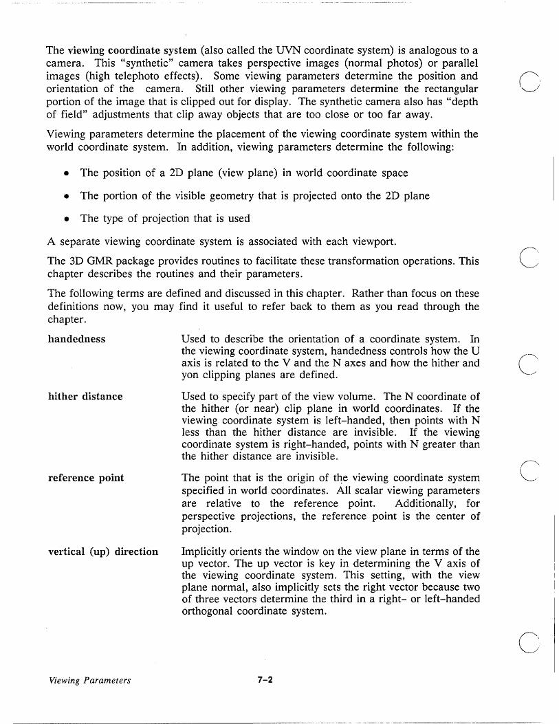
The viewing coordinate system (also called the UVN coordinate system) is analogous to a camera. This "synthetic" camera takes perspective images (normal photos) or parallel images (high telephoto effects). Some viewing parameters determine the position and ~ orientation of the camera. Still other viewing parameters determine the rectangular , __ ) portion of the image that is clipped out for display. The synthetic camera also has "depth of field" adjustments that clip away objects that are too close or too far away.
Viewing parameters determine the placement of the viewing coordinate system within the world coordinate system. In addition, viewing parameters determine the following:
• The position of a 2D plane (view plane) in world coordinate space
• The portion of the visible geometry that is projected onto the 2D plane
• The type of projection that is used
A separate viewing coordinate system is associated with each viewport.
The 3D GMR package provides routines to facilitate these transformation operations. This chapter describes the routines and their parameters.
The following terms are defined and discussed in this chapter. Rather than focus on these definitions now, you may find it useful to refer back to them as you read through the chapter.
handedness
hither distance
reference point
vertical (up) direction
Viewing Parameters
Used to describe the orientation of a coordinate system. In the viewing coordinate system, handedness controls how the U axis is related to the V and the N axes and how the hither and yon clipping planes are defined.
Used to specify part of the view volume. The N coordinate of the hither (or near) clip plane in world coordinates. If the viewing coordinate system is left-handed, then points with N less than the hither distance are invisible. If the viewing coordinate system is right-handed, points with N greater than the hither distance are invisible.
The point that is the origin of t~e viewing coordinate system specified in world coordinates. All scalar viewing parameters are relative to the reference point. Additionally, for perspective projections, the reference point is the center of projection.
Implicitly orients the window on the view plane in terms of the up vector. The up vector is key in determining the V axis of the viewing coordinate system. This setting, with the view plane normal, also implicitly sets the right vector because two of three vectors determine the third in a right- or left-handed orthogonal coordinate system.
7-2
... _. __ ._ ... _ .... - --_ .•..... _---

view distance
o
C) view plane
view plane normal
o viewing transformation
view volume
o
view window
o
The signed distance (in world coordinates) between the reference point and the view plane, along the direction of gaze. In other words, it is the N coordinate of the view plane.
For an orthographic projection, the results are independent of view distance since the projection is parallel to the N axis.
For perspective projections, the view distance alters the divergence of the projection rays between the center of projection (reference point) and the window bounds of the view plane. For perspective projections, view distance must be negative if the viewing coordinate system is right-handed and positive if the viewing coordinate system is left-handed.
For plan oblique and elevation oblique projections, changing the view distance slides the projection across the view plane.
The plane in the viewing coordinate system defined by N =
view distance. This is the plane in which the view window is specified.
The direction, specified in world coordinates, of the N axis of the viewing coordinate system. The view plane normal establishes the orientation in space of the view plane. The vector can have any length but the vector cannot be identically zero.
The view plane normal is the gaze direction in a left-handed viewing coordinate system, and points opposite the gaze direction in a right-handed system.
A process that maps world coordinate space into a view volume in viewing coordinate space.
The set of points in world coordinates between the hither and yon planes whose projections on the view plane lie within the window. For parallel projections the view volume is a parallelepiped with a rectangular cross-section. For perspective projections, the view volume is a frustrum, that is, a truncated pyramid.
A rectangular region of the viewplane that determines what portion of a projected image is displayed. Points in the region have coordinates satisfying:
7-3 Viewing Parameters

viewing coordinates
yon distance
umin < U < umax
vmin < v < vmax
N = view distance
A three-dimensional coordinate system whose axes are labled U, V, and N. For prespective, orthographic, and elevation oblique projections the U axis always corresponds to "right" on the screen and the V axis always corresponds to "up" on the screen. The N axis points into or out of the screen depending on the handedness of the' viewing coordinate system. In a left-handed system +N points into the screen.
The signed distance in world coordinates of the yon (or far) clip plane from the reference point. If the viewing coordinate system is left-handed, then points with N greater than the yon distance are invisible. If the viewing coordinate system is right-handed, points with N less than the yon distance are invisible.
The routines described in this section provide control over the minimal set of parameters required to specify perspective and parallel viewing transformations. They provide complete generality and attempt to minimize unintuitive side effects. These routines provide a solid basis on which to build an effective user interface. ('"
7.1 Specifying the Projection Type Routines:
GMR_$VIEW _SET_PROJECTION_TYPE GMR_$VIEW _SET_OBLIQUE GMR_$VIEW _INQ_PROJECTION_ TYPE GMR_ $VIEW _INQ_ OBLIQUE
There are two basic types of projection: parallel and perspective. Parallel projection is further divided into three types: 'orthographic, plan oblique, and elevation oblique (see Figure 7-2). Orthographic is the default. If you specify either plan oblique or elevation oblique, you can further modify the projection using GMR_$VIEW _SET_OBLIQUE. This section describes the different projection types.
Viewing Parameters 7-4
c'

o
o
o
o
Projection
Perspective
Figure 7-2. Projection Types
Elevation Oblique
GMR_$VIEW _SET_PROJECTION_TYPE specifies the projection type of a specified viewport as one of the following: perspective, orthographic, plan oblique, elevation oblique. The default is orthographic.
GMR_$VIEW _INQ_PROJECTION_TYPE returns the projection type of the specified viewport.
7.1.1 Parallel Projection
Parallel projection is used to represent the metric properties of an object (for example, distances and angles) at the expense of realism. For example, receding parallel lines remain parallel; this gives a somewhat distorted appearance to the drawing for the casual viewer. Parallel projection is well suited for working drawings. There are three types of parallel projection in 3D GMR: orthographic, plan oblique, and elevation oblique.
Orthographic projection is typically used to show the exact shape of any side perpendicular to the view plane normal. It is well suited for rectangular objects. The user typically creates several orthographic views in order to see the object from several angles at once (for example, top, front, and right).
A plan oblique projection is typically used to show the exact shape of one side of an object and uses a foreshortening ratio to shorten lines that are perpendicular to that one side. These shortened lines are always drawn vertically in a plan oblique projection. In the 3D GMR package lines receding from the viewer (lines perpendicular to the view plane and extending in the gaze direction) are drawn vertically downward on the screen. The side whose shape is preserved is drawn at an angle (the receding angle) to these vertical lines . The foreshortening ratio of a line is its projected length divided by its true length.
The receding angle is measured counterclockwise from the horizontal ("right") direction at which the U axis is displayed. The V axis is displayed at right angles to the U axis.
Elevation oblique is similar to plan oblique in that it also preserves the shape of one face of the object. Unlike plan oblique, that face is always shown upright. Lines receding from the viewer (that is, in the gaze direction) are foreshortened and drawn at a given
7-5 Viewing Parameters

angle to the horizontal. However, receding parallel lines give the illusion of divergence to the inexperienced viewer.
Elevation oblique is well suited for objects with detail on mainly one face (for example, a C~ radio). It is also widely used for building elevations.
Orthographic projection is the default. You can set it explicitly using GMR_$VIEW _SET_PROJECTION_TYPE. If you specify an oblique projection you can use GMR_$VIEW _SET_OBLIQUE to obtain various effects. These effects are based upon the foreshortening ratio and receding angle.
The foreshortening ratio (F) specifies how much lines perpendicular to the view plane are shortened in projection. Note that orthographic projection corresponds to the special case F = 0 of. elevation oblique or plan oblique projections.
When it is used for elevation oblique, the receding angle is measured counterclockwise from the positive U axis in the viewing coordinate system. The receding angle specifies the direction on the view plane onto which the positive gaze direction is projected.
Use GMR_$VIEW _SET_OBLIQUE to specify the foreshortening ratio and the receding angle for viewports using an oblique projection.
GMR_$VIEW _INQ_OBLIQUE returns the values of the foreshortening ratio and the receding angle if the specified viewport is using an oblique projection.
7.1.2 Perspective Projection
Perspective projection gives a realistic representation of an object as seen from an observer at a specific position. An object appears smaller the greater its distance from the observer. Parallel lines converge at a vanishing point (for example, railroad tracks give the apprearance of converging in the distance).
Perspective projections are often used for presentation purposes and in advertising. They do not usually make good working drawings because it is difficult to judge metric properties such as distances, sizes, and angles.
7.2 Specifying the View Plane Routines:
GMR_$VIEW _SET_REFERENCE_POINT GMR_$VIEW _SET_ VIEW _PLANE_NORMAL GMR_$VIEW _SET_VIEW_DISTANCE GMR_ $VIEW _INQ_REFERENCE_POINT GMR_$VIEW _INQ_ VIEW _PLANE_NORMAL GMR_$VIEW _INQ_ VIEW_DISTANCE
The view plane is specified by the reference point (R), the view plane normal (N), and the signed view distance (d) from the reference point to the plane, measured along the view
(", ,----. '
plane normal (see Figure 7-3). The view plane normal can have any length. CI
Viewing Parameters 7-6

o
o
o
o
y eye
-y7
~~j~ 3D Object
............ ~""'------X
y /+N /
eR
-N Gaze Direction
Observation position
R = Reference Point N = View plane normal
View Plane
y y
~~~ ......... ~""'------X
d = View Distance
z x
Figure 7-3. Specifying the View Plane in a Right-Handed System
GMR_$VIEW _SET_REFERENCE_POINT specifies a point in world coordinates that is the origin of the viewing coordinate system for a specified viewport. This is the point from which to measure clipping plane distances (hither and yon distances), and the distance to the view plane for both parallel and perspective projections. The default is (0, 0, 0) in the world coordinate system. The reference point is the center of projection for perspective viewing operations.
7-7 Viewing Parameters

GMR_$VIEW _INQ_REFERENCE_POINT returns the viewing reference point for a specified viewport.
GMR_$VIEW _SET_VIEW _PLANE_NORMAL specifies a world coordinate vector that is normal to the view plane of the specified viewport. This need not be a unit vector. The default is (0, 0, 1), along the positive z-axis of the world coordinate system.
The view plane normal is the gaze direction in a left-handed viewing coordinate system, and points opposite the gaze direction in a right-handed system (see Figure 7-4).
GMR_$VIEW_INQ_ VIEW_PLANE_NORMAL returns the view plane normal vector for the specified viewport.
GMR_$VIEW _SET_VIEW _DISTANCE specifies the signed distance from the reference point to the view plane. The distance is measured along the view plane normal for both rightand left-handed coordinate systems. The default distance is -1.0. The view distance for perspective projections must be negative for a right-handed viewing coordinate system and positive for a left-handed system.
GMR_$VIEW _INQ_ VIEW _DISTANCE returns the distance from the reference point to the view plane in the specified viewport.
7.3 Specifying the Viewing Coordinate System Routines:
GMR_ $VIEW _SET_COORD _SYSTEM GMR_$VIEW _SET_UP _VECTOR GMR_$VIEW _INQ_COORD_SYSTEM GMR_$VIEW_INQ_UP_ VECTOR
The viewing coordinate system (UVN) can be either a right- or a left-handed system. The default is right-handed. GMR_$VIEW_SET_COORD_SYSTEM sets the viewing coordinate system to right- or left-handed.
GMR_$VIEW_INQ_COORD_SYSTEM returns the coordinate system type (right- or C.' left-handed) of the specified viewport. _
For perspective, orthographic, and elevation oblique projections U corresponds to right on the screen and V corresponds to up. In a right-handed viewing coordinate system, N points opposite the gaze direction (in the direction from the screen to the operator). In a left-handed UVN system, N points in the gaze direction (see Figures 7-4, and 7-6, and 7-7).
In. general, the same view can be obtained in a right-handed UVN system as in a left-handed system. The effects of chaning handedness are nullified by simultaneously reversing the direction of the view plane normal and changing the signs of the view distance and the hither and yon distances.
Viewing Parameters 7-8
c

o
n ,----"I
o
o
N
RIGHT-HANDED (default)
V
u
N points opposite the direction of gaze.
V
LEFT-HANDED
N points in the direction of gaze.
u
Figure 7-4. Right- and Left-handed Viewing Coordinate Systems
The reference point is the origin of the viewing coordinate system (UVN system). The orientation of the viewing coordinate system is described as follows:
o The N axis is parallel to the view plane normal.
o The V axis is perpendicular to the N axis. More precisely, the V axis is the projection of the view up vector onto the N = 0 plane (see Figure 7-5).
o The U axis is determined by the V axis, the N axis, and the handedness of the UVN coordinate system. If U, V, and N are unit vectors, then U = N x V (cross product) for a left-handed system and U = V x N for a right-handed system.
Projection of View up Vector onto the N = 0 Plane
/
u
Figure 7-5. Determining the V Axis of the UVN Coordinate System
7-9 Viewing Parameters

GMR_$VIEW _SET_UP _VECTOR provides the final specification for orienting the viewing coordinate system. The routine specifies the world coordinate vector for establishing the orientation of the up direction (see Figure 7-5). The only restriction placed on this vector is that it be linearly independent of view plane normal. The default for the up direction is alignment with the positive y-axis of the world coordinate system (0, 1, 0).
GMR_$VIEW _INQ_UP _VECTOR returns a vector that represents the up direction of the specified viewport.
Figu~e 7-6 shows a left-handed viewing coordinate system (UVN system) with a positive view distance. Figure 7-7 shows a right-handed viewing coordinate system with a negative view distance.
R = Reference Point N = View plane normal
d = View Distance (positive)
z
y
Viewing Coordinate System
+N
v
Figure 7-6. A Left-handed Viewing Coordinate System
Viewing Parameters 7-10
u
x

o
0
r:J \
o
o
Z
R = N = d =
y
Reference Point
Viewing Coordinate System
-N
View plane normal
View Distance (negative)
v
u
X
Figure 7-7. A Right-handed Viewing Coordinate System
7.4 Specifying the View Volume The view volume bounds the part of the world that is to be clipped and projected. After the viewing coordinate system and "the view plane are established, the view volume is then determined by adding the following:
o Window boundaries (minimums and maximums in U and V)
o Hither and yon clip planes
• Projection type (see Section 7.1)
7.4.1 Orthographic Projection View Volume
An orthographic projection is the default projection type. For an orthographic projection, the view volume is in the shape of a rectangular parallelepiped (see Figures 7-8 and 7-9). The window on the view plane can be any upright rectangle in viewing coordinates. The window defines an infinite parallelepiped. An orthographic projection of a point (P) is
7-11 Viewing Parameters

defined as the intersection of the line through P (parallel to the N axis) with the view plane.
The hither and yon clip planes restrict the volume to a finite region. In Figures 7-8 and C,' 7-9, both hither and yon values are positive (measured from R along the negative N axis). --
N
V projection of P--.,
__ ----ft'!'
R
Window-"
View Plane
v dist
Hither Plane
h_dist
Vmax
;;;;,r--- View
Yon Plane
y dist
Volume
Vmin
Figure 7-8. Right-handed Orthographic Projection View Volume
Viewing Parameters 7-12
C,'

o
o
o
o
o
Reference Point
Yon Plane
Hither Plane
View Plane
Figure 7-9. Right-handed Orthographic Projection View Volume
Making either hither or yon negative places the reference point within the view volume. This is the case in the default view volume (see Figure 7-10). Notice that the default view volume in Figure 7-10 is not drawn to scale since the default hither and yon distances are very large (-10 10 and 1010 respectively).
7-13 Viewing Parameters
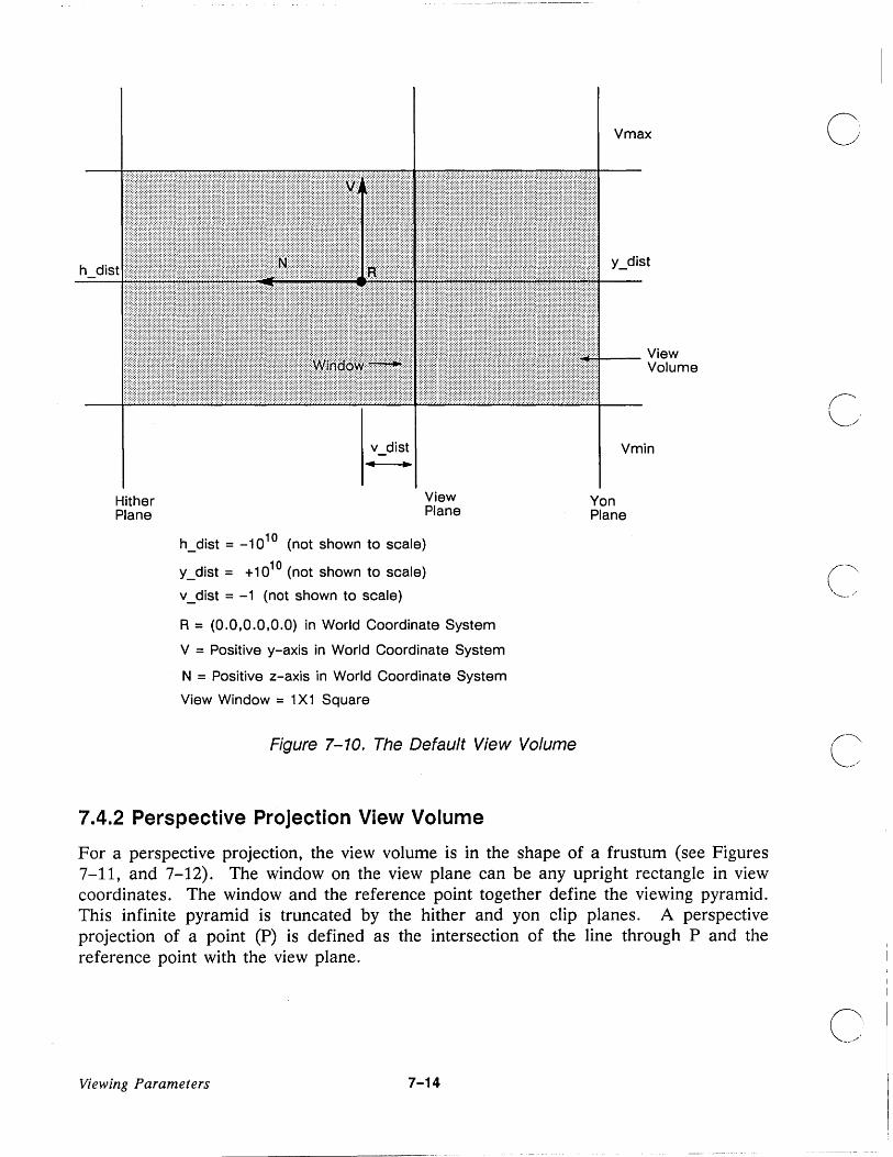
h dist
Hither Plane
View Plane
h_dist = _1010 (not shown to scale)
y_dist = +1010 (not shown to scale)
v_dist = -1 (not shown to scale)
R = (0.0,0.0,0.0) in World Coordinate System
V = Positive y-axis in World Coordinate System
N = Positive z-axis in World Coordinate System
View Window = 1 X1 Square
Figure 7-10. The Default View Volume
7.4.2 Perspective Projection View Volume
Vmax
y_dist
~ __ View Volume
Vmin
Yon Plane
For a perspective projection, the view volume is in the shape of a frustum (see Figures 7-11, and 7-12). The window on the view plane can be any upright rectangle in view coordinates. The window and the reference point together define the viewing pyramid. This infinite pyramid is truncated by the hither and yon clip planes. A perspective projection of a point (P) is defined as the intersection of the line through P and the reference point with the view plane.
Viewing Parameters 7-14

o
o
o
C)
o
v
+N R
View Plane
Hither Plane
___ View Volume
Yon Plane
Figure 7-11. Right-handed Perspective Projection View Volume
7-15 Viewing Parameters

+N
Reference Point
View Volume
\
View Plane
Hither Plane
Yon Plane
Figure 7-12. Right-handed Perspective Projection View Volume
7.4.3 Routines that Set and Modify the View Volume
Routines:
GMR_$VIEW _SET_WINDOW GMR_$VIEW_SET_HITHER_DISTANCE GMR_$VIEW_SET_YON_DISTANCE
Viewing Parameters 7-16
c
c
C' I
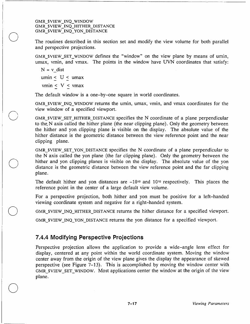
o
o
GMR_$VIEW _INQ_ WINDOW GMR _ $VIEW _ INQ_HITHER _ DISTANCE GMR_$VIEW_INQ_YON_DISTANCE
The routines described in this section set and modify the view volume for both parallel and perspective projections.
GMR_$VIEW _SET_WINDOW defines the "window" on the view plane by means of umin, urnax, vmin, and vmax. The points in the window have UVN coordinates that satisfy:
N = v dist
umin < U < urn ax
vmin < V < vmax
The default window is a one-by-one square in world coordinates.
GMR_$VIEW _INQ_ WINDOW returns the umin, umax, vmin, and vmax coordinates for the view window of a specified viewport.
GMR_$VIEW _SET_HITHER_DISTANCE specifies the N coordinate of a plane perpendicular to the.N axis called the hither plane (the near clipping plane). Only the geometry between the hither and yon clipping plane is visible on the display. The absolute value of the hither distance is the geometric distance between the view reference point and the near clipping plane.
GMR_$VIEW_SET_YON_DISTANCE specifies the N coordinate of a plane perpendicular to the N axis called the yon plane (the far clipping plane). Only the geometry between the hither and yon clipping planes is visible on the display. The absolute value of the yon distance is the geometric distance between the view reference point and the far clipping plane.
The default hither and yon distances are -1010 and 1010 respectively. This places the reference point in the center of a large default view volume.
For a perspective projection, both hither and yon must be positive for a left-handed viewing coordinate system and negative for a right-handed system. o GMR_$VIEW _INQ_HITHER_DISTANCE returns the hither distance for a specified viewport.
o
GMR_$VIEW _INQ_YON_DISTANCE returns the yon distance for a specified viewport.
7.4.4 Modifying Perspective Projections
Perspective projection allows the application to provide a wide-angle lens effect for display, centered at any point within the world coordinate system. Moving the window center away from the origin of the view plane gives the display the appearance of skewed perspective (see Figure 7-13). This is accomplished by moving the window center with GMR_$VIEW _SET_WINDOW. Most applications center the window at the origin of the view plane.
7-17 Viewing Parameters

PERSPECTIVE PROJECTION
RIGHT-HANDED SYSTEM
+N
v
R
Specifying the window off center creates a view volume in the shape of a skewed, truncated pyramid.
-N
Figure 7-13. Specifying the View Window Off Center on the View Plane
Viewing Parameters 7-18

o
o
o
o
The center of projection for perspective projections is the reference point used in establishing the view plane. To change the center of perspective projection while viewing a stationary object, you must move the reference point using GMR_$VIEW _SET_REFERENCE_POINT and then reset the gaze direction back to the object using GMR_$VIEW _SET_ VIEW _PLANE_NORMAL.
Changing just the reference point translates the view volume as a whole. Moving the reference point towards an object gives the same effect as physically moving towards the object. The center of projection, the view plane window, and the clipping planes all move together towards the object.
Increasing the magnitude of the view distance causes the perspective effect to decrease (like a telephoto lens) for a fixed object by moving the window ·away from the center of projection in the direction of the view plane normal. To do this, use GMR_$VIEW _SET_VIEW _DISTANCE. This may cause part of the fixed object to be clipped away unless the reference point is moved back at the same time.
Because the hither and yon clipping planes are tied to the reference point and not the view distance, the two clipping planes remain stationary with respect to the object when you change only the view distance. You can change the hither and yon clipping planes directly with GMR_$VIEW _SET_HITHER_DISTANCE and GMR_$VIEW _SET_YON_DISTANCE.
Setting the view plane normal allows the application to position the view plane in any direction except the up direction.
7.5 Copying View Parameters Routines:
GMR_$VIEW_SET_STATE GMR_$VIEW _INQ_STATE
Use GMR_$VIEW_INQ_STATE to retrieve the parameters of an existing view and then use GMR_$VIEW_SET_STATE to transfer the parameters to another view or to restore a view to a previous state. This allows you to set up standard view orientations (for example, standard orthogonal views such as top, front, right, and isometric) and change quickly between them.
GMR_$VIEW_SET_STATE accepts a record containing all viewing parameters. The default is the identity view transform along with the initial defaults for the individual parameters.
7.6 Application Specific Viewing Transformations Routines:
GMR_$VIEW _SET_TRANSFORM GMR_ $VIEW _INQ_ TRANSFORM
7-19 Viewing Parameters
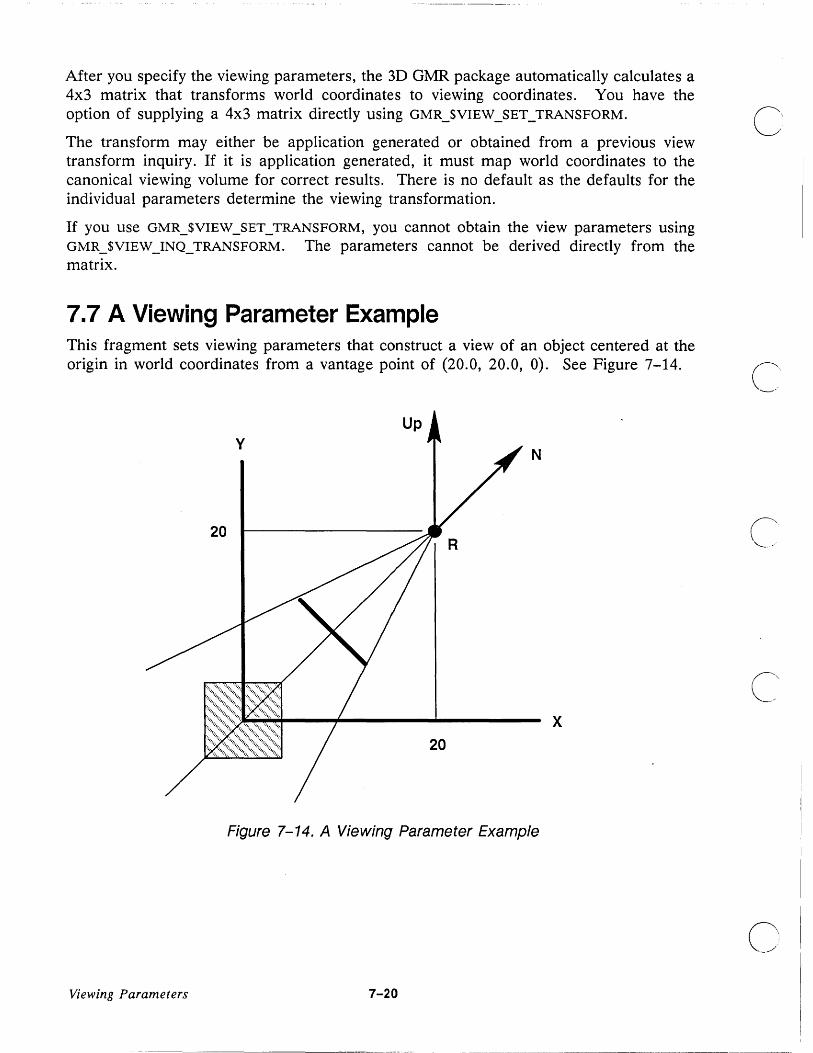
After you specify the viewing parameters, the 3D GMR package automatically calculates a 4x3 matrix that transforms world coordinates to viewing coordinates. You have the option of supplying a 4x3 matrix directly using GMR_$VIEW _SET_TRANSFORM.
The transform may either be application generated or obtained from a previous view transform inquiry. If it is application generated, it must map world coordinates to the canonical viewing volume for correct results. There is no default as the defaults for the individual parameters determine the viewing transformation.
If you use GMR_$VIEW _SET_TRANSFORM, you cannot obtain the view parameters using GMR_$VIEW _INQ_TRANSFORM. The parameters cannot be derived directly from the matrix.
7.7 A Viewing Parameter Example This fragment sets viewing parameters that construct a view of an object centered at the origin in world coordinates from a vantage point of (20.0, 20.0, 0). See Figure 7-14.
Up
N
x
Figure 7-14. A Viewing Parameter Example
Viewing Parameters 7-20
C' _.-"
c

o
o
o
o
o
VAR gmr_ $f3 _point_t .- 20, 20, ° ] ; gmr_ $f3 - vector - t .- 1, 1, ° ] ; gmr_ $£3 - vector - t .- 0, 1, ° ] ; gmr_ $£2 - limits - t .- -4, 4, -4,4 ] ; gmr_ $£ - t .- -1.0; gmr_ $£ - t .- -5.0; gmr_ $£ - t .- -30.0;
Ref_Point Normal Up_Vect Window H_dist V_dist Y_dist coord_sys proj vpid
gmr_$coord_system_t:= gmr_$coord_right; gmr_$projection_t:= gmr_$perspective; gmr_$viewport_id_t;
st status_t;
GMR_$VIEW_SET VIEW_PLANE_NORMAL( vpid, Normal, st ); GMR_$VIEW_SET_REFERENCE_POINT( vpid, Ref_Point, st ); GMR_$VIEW_SET_UP_VECTOR( vpid, Up_Vec, st );
{ { {
vpid is the viewport id of the viewport we wish to view the
} } }
GMR_$VI EW_SET_VI EW_D I STANCE ( vpid, V_dist, st ); GMR_$VIEW_SET_HITHER_DISTANCE( vpid, H_dist, st ); GMR_$VI EW_SET_YON_D I STANCE ( vpid, Y_dist, st ); GMR_$VIEW_SET_WINDOW( vpid, Window, st ); GMR_$VIEW_SET_PROJECTION_TYPE( vpid, proj, st ); GMR_$VIEW_SET_COORD_SYSTEM( vpid, coord_sys, st );
{ object in. These calls} { can be made in any } { order. }
7-21 Viewing Parameters

c
c
C~

o
o
o
o
o
Chapter 8
Displays and Viewports
This chapter describes the last two stages in the viewing pipeline: the transformation of viewing coordinates to logical device coordinates and then to device coordinates. The 3D GMR package performs these transformations automatically after you define a viewport or use the default viewport.
8.1 Viewports The 3D GMR package has four modes that control the display in relation to the screen: borrow, direct, main-bitmap, and no-bitmap (see Chapter 2).
In borrow, direct, and main-bitmap modes, graphic output is produced according to the mode established when the 3D GMR package is initialized:
o On the entire screen in borrow mode
e On a Display Manager window in direct mode
o In a main memory bitmap in main-bitmap mode
You can easily change your program to use one or another of these modes by changing one option in the initialization routine GMR_$INIT.
Graphics output occurs· by way of viewports that are defined in logical device coordinates. The view is a picture taken by the "synthetic camera" described in Chapter 7. Moving or scaling a view moves or scales what you see through the viewport.
8-1 Displays and Viewports

When you initialize 3D GMR, the GMR_$INIT routine establishes a single viewport that fills the default LDC area (see Chapter 2). The default viewing parameters are described in Chapter 7. You can perform the following operations on viewports:
• Change the viewing parameters (see Chapter 7).
• Create additional viewports. The logical device coordinate area can be divided into multiple viewports (see Figure 8-1). Up to 64 simultaneous viewports are supported.
• Change the size and border width of a viewport.
• Change how a viewport presents a metafile (background color, echo type, refresh method).
• . Specify that you want parts of the metafile displayed and moved independently in separate viewports.
• Display different metafiles in different viewports simultaneously.
Displays and Viewporfs 8-2
c
C".' "

o
o
o
o
Screen Display Manager Windows
Max Device Limits Viewports
Device Limits I LDe Limits
Figure 8-1. Two Viewports Created within Default LDC Limits
8.2 Device Coordinate Systems Routines:
GMR_$INQ_CONFIG GMR_$COORD_INQ_DEVICE_LIMITS GMR_$COORD_INQ_MAX_DEVICE G MR_ $ COORD _ INQ_ LDC _LIMITS GMR_$COORD_SET_DEVICE_LIMITS GMR_$COORD_SET_LDC_LIMITS
This section describes device coordinates and logical device coordinates (see Figure 8-6). Device coordinates are an integer coordinate system. Logical device coordinates are a
8-3 Displays and Viewports

floating point system. Both are used to specify positions in the bitmap used by the 3D GMR package.
8.2.1 Device Limits
3D GMR uses three types of device limits:
• Maximum device limits
• Device limits
• Logical device limits
These three types are provided to make 3D GMR device independent. You can run most programs that include 3D GMR routines on any DOMAIN node without modifying the program. The 3D GMR package rescales viewports and views according to the area
C:
available for logical device coordinates. This means that programs containing 3D GMR (.--~
display-time routines will display all viewports for any logical device coordinate area. \-----/
Maximum Device Limits The maximum device limits are defined to be the size of the requested bitmap in pixels after the bitmap is trimmed to fit into the Display Manager window (direct mode) or the screen (borrow mode).
In direct mode the maximum device limits are smaller than the Display Manager window. The Display Manager requires a 5-pixel border between the maximum bitmap size (that
is, the maximum device limits) and the Display manager window.
Device Limits Device limits define the subregion of the maximum device limits that is available to 3D GMR (see Figure 8-2). This is the only area in which 3D GMR can display. The default is the largest centered square region within the maximum device limits. Your application may change these limits to any values less than or equal to the maximum device limits (most applications do not need to do this).
Displays and Viewporfs 8-4
(' \..._- '
c

o
o
o
o
o
Display Manager Window
(500,400)
Max. Device Limits
(0,0) (75,20)
Device Limits
Figure 8-2. Maximum Device Limits and Device Limits
Logical Device Limits The logical device limits describe exactly the same area as the device limits (see Figure 8-3). The resulting- logical device coordinates provide a convenient coordinate system that is independent of actual bitmap dimensions. The 3D GMR package uses this coordinate system to map viewport data to device coordinates.
This is a three-dimensional coordinate system. The z-coordinate of the LDC limits makes the viewport into a volume that is mapped to the view volume in world coordinates. This correspondence is useful for coordinate conversions between LDC and world coordinates. See GMR_$COORD_LDC_TO_WORLD and GMR_$COORD_LDC_TO_WORLD in Section 8.4.
The default logical device coordinates range from (0.0, 0.0, 0.0) to (1.0, 1.0, 1.0).
8-5 Displays and Viewports

(425,380) ----ill.... (1.0,1.0)
(75,20) ----II.... (0.0,0.0)
Figure 8-3. Device Limits Mapped to Logical Device Limits
NOTE: Logical device and device coordinate systems have their origin in the lower left-hand corner with y increasing up and x increasing to the right. This is different from the DOMAIN Graphics Primitives package which has (y = 0) in the top left-hand corner, with y increasing down.
8.2.2 Device Limits and Window Grow Operations
After a Display Manager window-grow operation, the default is to maintain the same aspect ratio (ratio of height to width) of the viewports. This means that the logical device coordinates and device coordinates maintain the same aspect ratio.
You can change the default operation by writing your own refresh routines and calling them through GMR_$DM_REFRESH_ENTRY (see Figure 8-4 and Chapter 9). For example, you can keep the object in the window the same size but let the viewport grow, thus showing more of a large object. Another option is to write a routine that refreshes overlapping viewports in a particular order.
Displays and Viewporfs 8-6
c

o
o
f) ~
o
o
Default behavior. Possible user-defined action specified
Aspect ratio maintained.
Figure 8-4. Window Grow Operations
Use GMR_$INQ_CONFIG to determine the configuration of the display device. You can use this information to assign different attributes to a metafile displayed on a color node than to a metafile displayed on a monochrome node (see Chapter 12).
8-7 Displays and Viewports

GMR_$INQ_CONFIG returns the number of bit planes and the size of the screen. The size is returned as a two-element array fo 2-byte integers. For example, on a 1024x800 display, the first integer contains 1024 and the second contains 800.
GMR_$COORD_SET_DEVICE_LIMITS specifies the limits of device space. This is a subrange of the available maximum device limits.
GMR_$COORD_INQ_DEVICE_LIMITS returns the portion of the bitmap used to map to logical device coordinates.
GMR_$COORD_INQ_MAX_DEVICE returns the maximum range of the device coordinates. The device limits cannot be larger than the values returned by this routine.
GMR_$COORD_SET_LDC_LIMITS specifies the limits of 3D logical device coordinate space.
GMR_$COORD_INQ_LDC_LIMITS returns the 3D device coordinates to which the logical device limits are mapped.
8.3. Window to Viewport Mapping After you have defined the viewports, the 3D GMR package automatically transforms the 2D area defined by the window onto the viewport (see Figures 8-5 and 8-6).
Figure 8-5. Viewport to LOC Mapping
Notice in Figure 8-5 that the aspect ratio of the window and the viewport are the same. If the aspect ratios are different, the image is stretched to fit into the viewport. Note that a 3D GMR window is not equal to a Display Manager window. Use the routine GMR_$VIEW _SET_WINDOW to set the view window· (see Chapter 7).
After mapping the viewing coordinates to logical device coordinates, the 3D GMR package automatically maps the logical device coordinates of the viewport to device coordinates. This is the last step in the viewing pipeline (see Figure 8-6).
Displays and Viewports 8-8
c'
r

3D Element data (modeling coordinates)
o Modeling Transformations
3D I World C ordinates
Viewing Transformation
3D Viewing Coordinates
o 20 Device Coordinates
Figure 8-6. The Viewing Pipeline
8.4 Coordinate Transformation Routines o Routines:
o
o
GMR_$COORD_DEVICE_TO_LDC GMR_$COORD_LDC_TO_DEVICE GMR_$COORD_LDC_TO_ WORLD GMR_$COORD_ WORLD_TO_LDC
The routines described here make it possible to convert one set of coordinates to another and to retrieve the values stored for specified coordinate systems.
GMR_$COORD_DEVICE_TO_LDC converts device coordinates to logical device coordinates. The transformation from device coordinates to logical device coordinates is determined by the limits returned by the routines GMR_$COORD_INQ_DEVICE_LIMITS and GMR_$COORD_INQ_LDC_LIMITS (see Section 8.2).
GMR_$COORD_LDC_TO_DEVICE converts logical device coordinates to device coordinates.
GMR_$COORD_LDC_TO_ WORLD maps a point in logical device coordinates into world coordinates via the viewing parameters associated with the given viewport.
GMR_$COORD_ WORLD_TO_LDC returns the logical device coordinates of a point specified in world coordinates.
8-9 Displays and Viewports
8.5 Viewport Routines Routines:
GMR_$VIEWPORT_CLEAR GMR_$VIEWPORT_CREATE GMR_$VIEWPORT_DELETE GMR_$VIEWPORT_INQ_BG_COLOR GMR_$VIEWPORT_INQ_BORDER GMR_$VIEWPORT_INQ_BOUNDS GMR_$VIEWPORT_INQ_STATE GMR_$VIEWPORT_MOVE GMR_$VIEWPORT_REFRESH GMR_$VIEWPORT_SET_BG_COLOR GMR_$VIEWPORT_SET_BORDER GMR_$VIEWPORT_SET_BOUNDS GMR_$VIEWPORT_SET_STATE
The viewport routines listed above allow you to create multiple viewports and manipulate viewports in several ways.
8.5.1 Changing a Viewport's Appearance
The routines described in this section allow you to change the way the viewport looks on the screen.
Setting Viewport Bounds To change the dimensions of the viewport, use GMR_$VIEWPORT_SET_BOUNDS. To redefine the viewport with this routine, you must provide the coordinates of any two diagonally opposite corners. Coordinates are expressed in logical device coordinates (LDC). By default, the lower left corner in x and y of LDC space is (0.0, 0.0, 0.0). The upper right corner is (1.0, 1.0, 1.0).
GMR_$VIEWPORT_INQ_BOUNDS returns the bounds of a specified viewport, in logical device coordinates.
Moving a Viewport GMR_$VIEWPORT_MOVE translates a specified viewport, carrying the view with it.
Viewport Contents Before you can view a structure, you must assign it to a viewport using GMR_$VIEWPORT_SET_STRUCTURE. To display the structure you must clear and refresh the viewport.
GMR_$VIEWPORT_CLEAR clears the specified viewport to the background color.
GMR_$VIEWPORT_REFRESH redraws the contents of a viewport according to the specified viewport's associated refresh state.
Displays and Viewports 8-10

Backgrounds and Borders GMR_$VIEWPORT_SET_BG_COLOR specifies the color ID and intensity used for the background of the specified viewport.
GMR_$VIEWPORT_INQ_BG_COLOR returns the color ID and intensity used for the background of the specified viewport.
To set, inquire, and clear the background color of the entire display (up to the maximum device limits) use the following calls:
GMR_$VIEWPORT_SET_BORDER sets the border width of a viewport to the specified values o in pixels.
(j
o
GMR_$VIEWPORT_INQ_BORDER returns the border width of a specified viewport in pixels. Borders extend outside the viewport and are optional.
The default width is 1 for each border. Viewport borders are drawn with color value 1 for compatibility with monochrome nodes.
8.5.2 Using Multiple Viewports
The routines described in this section allow you to create and manipulate multiple viewports.
Creating Viewports When you initialize the graphics metafile package in direct, borrow, and main-bitmap modes, the package does the following:
• Creates one viewport
• Makes the viewport fill the maximum device limits
o Assigns viewport ID number 1 to the viewport
To use multiple viewports, you can create additional viewports with GMR_$VIEWPORT_CREATE. The 3D GMR package assigns numbers to viewports as they are created. The viewport established with GMR_$INIT has the number 1. When you create an additional viewport, it is assigned a number.
GMR_$VIEWPORT_CREATE creates a new viewport and assigns (and returns) a unique viewport ID.
Currently, overlapping viewports are not supported or prevented. Overlapping may cause a viewport to "pop" when not expected due to an update to the image.
8-11 Displays and Viewports
Before you create a second viewport, you may want to change the bounds of the first viewport to provide sufficient room for the second viewport. If you want to have overlapping viewports, you may want to create your own refresh routine to deal with overlapping (see Figure 8-4). You can call your refresh routine using GMR_$DM_REFRESH_ENTRY.
Deleting a Viewport GMR_$VIEWPORT_DELETE deletes a specified viewport.
Modifying all Viewport Parameters GMR_$VIEWPORT_INQ_STATE returns all of the parameters of an individual viewport. You can use this call with GMR_$VIEWPORT_SET_STATE to set all or part of the viewing parameters. These two calls are useful when you want to create a new viewport that is similar to an existing viewport. For example:
GMR_$VIEWPORT_INQ_STATE(vpidl, array_size, size, view_state, status); GMR_$VIEWPORT_SET_STATE(vpid2, view_state, status); GMR_$VIEWPORT_REFRESH(vpid2, status);
8.6 Sample Procedures The fragments included in this chapter are taken from Sample2, which is on-line in Pascal, FORTRAN, and C under the following names:
domain _ examples/ gmr3d/sample2. pas domain _ examples/ gmr3d/sample2.c domain_examples/gmr3d/sample2.ftn
Sample2 is a menu-driven program which displays a wireframe teapot and accepts commands to change the way the teapot is viewed. This program runs on all configurations in either borrow or display mode. To move the cursor, you can use a mouse, puck, or arrow keys. To pick a button, use the first mouse or puck button or the space bar.
8.6.1 Initialize 3D GMR
This fragment prompts you for the display mode - borrow or direct. It then initializes 3D GMR and inquires the configuration. The configuration determines the colors that are set and the use of double buffer mode. It prompts you for the name of the metafile to display and opens that metafile.
PROCEDURE init;
VAR mode : string; display_mode : gmr_$display_mode_t; picked : boolean; i : integer;
Displays and Viewporfs 8-12
(') \...---~/

o
o
o
o
BEGIN
write('Type B for Borrow mode, D for Direct mode: ');
REPEAT picked := TRUE; readln(mode); ('B'),
CASE mode[l] OF
('b') : display_mode := gmr_$borrow; ('D'), ('d') : display_mode := gmr_$direct; OTHERWISE BEGIN write('INVALID ANSWER. Type B for Borrow mode, D for Direct mode: '); picked .- FALSE; END; END; UNTIL (picked = TRUE); writeln;
gmr_$init(display_mode, stream_$stdout, bitmap_size, 8, status); check;
gmr_$inq_config( display_mode, stream_$stdout, num_planes, size, status); check;
END;
8.6.2 Procedures to Change a View
The following occurs in these program fragments:
1. Receive instruction from menu button to process menu_item.
2. Execute do_button depending on the value of menu_item.
3. Execute the "rotate" procedure if necessary.
4. Set the viewing parameters with set_object_viewyarms.
5. Refresh the viewport if the display flag is true.
1. Process menu Instruction. In this fragment, assume that either a mouse button or the space bar is depressed while the cursor is over a menu item.
PROCEDURE process_commands;
VAR end_flag display_flag position event ch
boolean; boolean; gmr_$f3_point_t; gmr_$event_t; char;
8-13 Displays and Viewports

IF «(event = gmr_$buttons) AND (ch = 'a'» OR {1st mouse button} «event = gmr_$keystroke) AND (ch = ' '») THEN {space bar} BEGIN do_button (menu_item , end_flag, display_flag); {calls do_button (#2)} IF (display_flag) AND (menu_item <> 0) THEN BEGIN set_teapot_view_parms; display_teapot;
{calls set teapot_view_parms (#4)} {calls display_object (#5)}
END; END;
2. Act on the value of menu item.
PROCEDURE do_button(IN menu_item integer; OUT end_flag display_flag: boolean);
BEGIN
end_flag .- FALSE; display_flag .- FALSE;
CASE menu_item OF
1: {Rotate counter clockwise.} BEGIN rotate(tea_ref.x, tea_ref.y, 10.0); rotate(tea_normal.x, tea_normal.y, 10.0); display_flag .- TRUE; END;
2: {Rotate clockwise.} BEGIN rotate (tea_ref. x, tea_ref.y, -10.0); rotate(tea_normal.x, tea_normal.y,-10.0); display_flag .- TRUE; END;
3: {Zoom in.} BEGIN tea_window.xmin .- tea_window.xmin * 0.8; tea_window.xmax .- tea_window.xmax * 0.8; tea_window.ymin .- tea_window.ymin * 0.8; tea_window.ymax .- tea_window.ymax * 0.8; display_flag .- TRUE; END;
4 : {Zoom out.} BEGIN tea_window.xmin .- tea_window.xmin * 1.25;
Displays and Viewporfs 8-14
boolean; OUT
c'
c
I
C' i
o
o
o
END;
o
tea window.xmax .- tea_window.xmax * 1.25; tea_window.ymin .- tea_window.ymin * 1.25; tea_window.ymax .- tea_window.ymax * 1.25; display_flag .- TRUE; END;
5: {Perspective Projection.} IF (tea_proj <> gmr_$perspective) THEN BEGIN tea_proj := gmr_$perspective; display_flag .- TRUE; END;
6: {Orthographic projection.} IF (tea_proj <> gmr_$orthographic) THEN BEGIN tea_proj := gmr_$orthographic; display_flag .- TRUE; END;
7: {Single-buffer.} IF num_planes >= 4 THEN IF buffer mode <> gmr_$single_buffer THEN BEGIN buffer_mode := gmr_$single_buffer; gmr_$dbuff_set_mode (buffer_mode , status); check; gmr_$display_clear_bg(status); check; gmr_$display_refresh(status); check; END;
8: {Double-buffer.}
9
IF num_planes >= 4 THEN IF buffer_mode <> gmr_$double_buffer THEN BEGIN buffer_mode := gmr_$double_buffer; gmr_$dbuff_set_mode(buffer_mode, status); check; current_buffer := gmr_$lst_buffer; gmr_$dbuff_set_select_buffer (current_buffer , tea_vpid, status); check; gmr_$display_clear_bg(status); check; gmr_$display_refresh(status); check; END;
{Exit.} end_flag .- TRUE;
END; {case}
8-15 Displays and Viewports

3. Calculate viewing rotation if necessary. This routine rotates x and y theta degrees.
PROCEDURE rotate( VAR x, y : REAL; IN theta REAL) ;
CONST convert 0.01745329;
VAR c, s, z REAL;
BEGIN c .- COS( theta * convert ) ;
s .- SIN( theta * convert ) ; z .- c * x + s * y; y .- -s * x + c * y; x .- z· ,
END;
4. Set viewing parameters.
BEGIN
gmr_$view_set_window(tea_vpid, tea_window, status); check; gmr_$view_set_reference_point(tea_vpid, tea_ref, status); check; gmr_$view_set_view_plane_normal(tea_vpid, tea_normal, status); check; gmr_$view_set_up_vector(tea_vpid, tea_up, status); check; gmr_$view_set_projection_type(tea_vpid, tea_proj, status); check; gmr_$view_set_hither_distance(tea_vpid, tea_hd, status); check; gmr_$view_set_yon_distance(tea_vpid, tea_yd, status); check; gmr_$view_set_view_distance(tea_vpid, tea_vd, status); check;
END;
5. Display the object in the revised viewport. This fragment displays the viewport with ID vpid. If double-buffer mode is in effect, the current_buffer is updated and the new buffer is selected.
PROCEDURE display_teapot;
BEGIN
IF buffer_mode = gmr_$double_buffer THEN BEGIN IF current_buffer = gmr_$1st_buffer THEN current_buffer .- gmr_$2nd_buffer ELSE current_buffer ,- gmr_$1st_buffer;
Displays and Viewports 8-16
r~
\ \ ........... " ~/

(j
o
o
gmr_$dbuff_set_select_buffer (current_buffer , tea_vpid, status); check; END;
{ You do not need to clear the viewport in double-buffer mode because the opposite buffer is cleared in gmr_$dbuff_set_display_buffer.}
IF buffer_mode = gmr_$single_buffer THEN BEGIN gmr_$viewport_clear(tea_vpid, status); check; END;
gmr_$viewport_refresh(tea_vpid, status); check;
IF buffer_mode = gmr_$double_buffer THEN BEGIN gmr_$dbuff_set_display_buffer(current_buffer, tea_vpid, status); check; END;
END;
8-17 Displays and Viewports

CI
r .......... -..
c

o
o
o
o
Chapter 9
Display-Time Features
Display-time routines allow you to control how graphic output is displayed. These routines do not affect the contents of the file. They affect the portion, location, and appearance of a structure on the screen.
9.1 Displaying a Structure Use the following procedure to display a structure in a viewport:
1. Assign a structure to the viewport using GMR_$VIEWPORT_SET_STRUCTURE (see Section 2.8).
2. Clear the viewport using GMR_$VIEWPORT_CLEAR (this is optional).
3. Refresh the viewport using either
GMR_$VIEWPORT_REFRESH or GMR_$DISPLAY_REFRESH
9.2 Refreshing the Display Routines:
GMR_$VIEWPORT_CLEAR GMR_$VIEWPORT_REFRESH GMR_$DISPLAY_REFRESH
o GMR_$VIEWPORT_CLEAR clears the specified viewport to the background color.
9-1 Disp/ay-Time Features

GMR_SVIEWPORT_REFRESH updates the display in a specified viewport.
GMR_SVIEWPORT_CLEAR and GMR_SVIEWPORT_REFRESH are often written into a single procedure. For example: C~
PROCEDURE display_viewport(IN vpid: gmr_$viewport_id_t); BEGIN gmr_$viewport_clear(vpid, status); gmr_$viewport_refresh(vpid, status); END;
GMR_SDISPLAY_REFRESH redisplays all the viewports with a refresh state defined as GMR_SREFRESH_WAIT, GMR_SREFRESH_UPDATE, or GMR_SREFRESH_PARTIAL.
9.2.1 User Defined Refresh
Routine:
GMR_SDM_REFRESH_ENTRY
GMR_SDM_REFRESH_ENTRY allows you to modify the way that the display is refreshed as the result of a Display Manager command to refresh or pop a window. This routine calls a user-defined routine to refresh the display. Some uses of this routine are the following:
• Refreshing overlapping views in a particular order.
• After a window grow operation, keeping the object the same size but letting the viewport grow, thus showing more of a large object.
• Changing the logical device coordinate range
• Changing the device coordinate range
• Clearing the background.
• Invoking GMR_SDISPLAY_REFRESH to redisplay all viewports
This routine requires that you pass a pointer-to-procedure data type. Pointer-to-procedure data types are an extension of the Pascal language (see the DOMAIN Pascal Language Reference). Refer to the example in the DOMAIN 3D Graphics Metafile Resource Call Reference for the calling sequence required in the user-defined routine.
Successive calls to GMR_SDM_REFRESH_ENTRY override previously defined entry points.
FORTRAN Users To pass procedure pointers in FORTRAN, first declare the subroutines to be passed as EXTERNAL. Then pass their names using the IADDR function to simulate the Pascal pointer mechanism. For example:
Display-Time Features 9-2
c'
o
o
o
o
o
EXTERNAL REFRESH_WINDOW
In FORTRAN, use 0 (not NIL) to indicate a zero value.
9.2.2 Establishing a Refresh State
Routines:
GMR_$VIEWPORT_SET_REFRESH_STATE GMR_$VIEWPORT_INQ_REFRESH_STATE
GMR_$VIEWPORT_SET_REFRESH_STATE allows you to control the frequency at which the display in a viewport is refreshed. This routine allows you to change the metafile and have the package automatically update one or more viewports to incorporate these changes, without calling a refresh routine. One use of this feature is during a fast redrawing operation as an object is moved across the screen.
GMR_$VIEWPORT_SET_REFRESH_STATE allows you to set the refresh state of a specified viewport.
GMR_$VIEWPORT_INQ_REFRESH_STATE returns the value of the refresh state of a specified viewport.
Refresh states are described in Section 11.5.
9.2.3 Setting and Clearing the Background Color
Routines:
GMR_$DISPLAY_SET_BG_COLOR GMR_$VIEWPORT_SET_BG_COLOR GMR_$DISPLAY_CLEAR_BG GMR_$DISPLAY_INQ_BG_COLOR GMR_$VIEWPORT_INQ_BG_COLOR
GMR_$DISPLAY_SET_BG_COLOR sets the background color and intensity for the display. You can specify the current Display Manager window background color, or specify a particular color and intensity. Use GMR_$VIEWPORT_SET_BG_COLOR to set the background color and intensity of individual viewports.
GMR_$DISPLAY_CLEAR_BG clears the background of the display to its color setting. The background is cleared up to the device limits.
In direct mode, the default color is the Display Manager window color. In borrow mode, it is color ID O.
9-3 Disp/ay-Time Features
GMR_$DISPLAY_INQ_BG_COLOR returns the current background color and intensity for the display. Use GMR_$VIEWPORT_INQ_BG_COLOR to retrieve the background color and intensity of individual viewports.
9.3 Using Double-Buffering When an application rapidly changes images, double-buffering can improve the appearance of this process. Double-buffering partitions the video memory into two buffers and therefore limits the number of available colors (see Tables 12-1 through 12-6). For example, on an eight-plane system, the 3D GMR technique for double-buffering allows the use of seven definable colors and black. On a four-plane system, only black and white are used.
3D GMR maintains a separate color map and color range table for double-buffering mode. The default single buffering mode has its own color map and color range table. This makes it possible to switch between the two modes at rendering time. Switching to
c
or from double-buffering mode is a change in the color map; hence, the color map is sent ( to the display device at the next viewport update. This means that the colors displayed in \,-_/' all viewports may change because of the switch between modes.
Calls to the routines for double-buffering are ignored when a monochrome display device is used.
Refer to Chapter 12 for descriptions of the double-buffering routines.
9.4 Viewport-based Visibility Criteria At display time, you can decide which structures and primitive elements will be visible. This allows you to display specific types or combinations of structures and elements.
There are four ways to control visibility on a viewport basis: culling, the structure mask, the structure value, and name sets. These routines are described in the five sections below.
Culling lets you display structures based on their size (see Figure 9-1). At display time, r--", the projection of the bounding box of a structure is compared to an area in square device ~ " coordinates. If the projected area of the bounding box is smaller than the area, the structure is not displayed. A bounding box includes all elements in a structure and all structures that it instances (see Chapter 13).
Each structure has a value and a mask that you can assign using GMR_$STRUCTURE_SET_ VALUE_MASK (see Section 2.7). At display time, the value and the mask are compared to the viewport's visibility range and visibility mask to determine whether the structure and its subtrees are displayed (see Figure 9-1).
Additionally, the visibility of primitives within visible structures can be controlled using name sets (see GMR_$ADD_NAME_SET and GMR_$REMOVE_NAME_SET in Chapter 4). At display time, the names in the current name set are compared to the viewport's invisibility filters (see Figure 9-2). The invisibility filters consist of an inclusion set and an exclusion C set that determine which elements are displayed (Section 9.4.3). _/~I
Display-Time Features 9-4

o
o
o
o
o
Structure Viewport
Structure Value .... Visibility range -Structure Mask
.... Visibility mask -Bounding Box ... Culling area -
For the structure to be visible:
1. The structure value must be within the viewport's visibility range. 2. The logical AND of the structure mask and the viewport visibility mask
must be non-zero.
3. The projected area of the bounding box of the structure (including its subgraphs) must be larger than the culling area size.
Figure 9-1. Structure Visibility Criteria
VIEWPORT PRIMITIVE
Inclusion Set Name Set
Exclusion Set
For a primitive within a structure to be visible:
Either all names in the current name set must be absent from the viewport invisibility inclusion set or at least one name must be in the viewport invisibility exclusion set.
Figure 9-2. Primitive Visibility Criteria
9.4.1 Using Visibility Features
Use visibility values and masks when you want to control the display of entire subtrees. This is the most efficient way to selectively display different parts of the metafile. A structure that is not visible is not traversed, nor are any of its subtrees.
Use name sets when you want to control the display of primitives within a structure. Name sets are a less efficient means of controlling visibility because they do not affect the traversal of the metafile. If primitive elements within a structure are invisible because of the current name set, the 3D GMR package still processes any instance elements that are referenced by the structure.
9-5 Display-Time Features

Use culling when you want to control the visibility of the details of an object. For example, in a zooming operation you can turn off the display of objects that are too small to see clearly.
9.4.2 Culling
Routines:
GMR_$VIEWPORT_SET_CULLING GMR_$VIEWPORT_INQ_CULLING
GMR_$VIEWPORT_SET_CULLING allows the display of only those structures that are larger than a specific screen-space area. When culling is enabled, the following structures are not rendered: all those structures with an approximate projected area in square device coordinates (i.e., number of pixels covered) that is less than a specified value.
The projected area of a structure is approximated by the projection of its bounding box ~ (see Chapter 13). GMR_$VIEWPORT_INQ_CULLING returns the current minimum structure \._ .. / size, and the enabled state of culling in the specified viewport.
When culling is turned on, structures are culled regardless of their visibility values or name sets.
Use culling when you don't want to take the time to draw structures that are too small to see clearly. For example, when you display a large assembly, you may not want to display all of the bolts. But as you zoom up on a portion of the assembly the individual bolts should be displayed. By turning culling on, the bolts will be displayed after they are zoomed to a specified screen space size.
To make effective use of culling, details should be kept in structures that are spatially separated. For example, if all of the bolts are in the same structure, then culling will not affect their display because the structure covers a large screen space area. But if each bolt is in a separate structure (or if one bolt is instanced multiple times in different locations), then culling can be effective.
NOTE: If you turn anchor clipping off and turn culling on, then text within a structure that would have been culled is still drawn.
9.4.3 Structure Mask and Visibility
Routines:
GMR_$VIEWPORT_SET_ VISIBILITY GMR_$VIEWPORT _INQ_ VISIBILITY
The structure mask is used to identify certain classes of objects as candidates for visibility and picking (see Chapter 10 ). The structure mask permits you to define up to 32 distinct classes and to toggle them on and off independently. ~) ,,-,/
Display-Time Features 9-6
- ---------- --------------

o
o
o
o
o
Structure Mask Example This example uses the structure mask to determine visibility for the floor plan, electrical systems, and plumbing systems on a specific floor of a bUilding. The lowest bit (1) is set in the mask in all structures containing floor plan data; the next lowest bit (2) in structures containing plumbing data; and the third bit in structures containing data for electrical systems. Higher bits can give higher structure values to other categories of structures. Figure 9-3 shows the results for viewport visibility masks of 1, 2, 5, and 7.
Structure Mask
10101011 1 101011 101 1011 1010 1
Floor Plan Structures
Plumbing Structures
Electrical Structures
Viewport Visibility Masks
0 0 0 1 Displays only Floor Plan Structures
0 0 1 0 Displays only Plumbing Structures
0 1 0 1 Displays Floor Plan and Electrical Structures
0 1 1 1 Displays all three groups of Structures
Figure 9-3. Structure Mask Example
9.4.4 Structure Value and Visibility
The structure value is an integer and is subject to a range test. The structure value is compared against the viewport's visibility and pick ranges to determine visibility and pick eligibility (see Chapter 10). You can use this feature to identify specific combinations of structures.
Structure Value Example In this example, the display of a building, all of the objects on one floor can have structure values within a certain range (see Figure 9-4).
9-7 Display-Time Features

Structure Values
IT] First Floor Structures
CD Second Floor Structures
o Third Floor Structures
Viewport Visibility Range
Min Max
IT] IT] Displays First Floor Structures only
o 0 Displays Third Floor Structures only
IT] 0 Displays Structures on all Three Floors
Figure 9-4. Structure Value Example
By combining the viewport visibility ranges and visibility masks in the above examples, you can display different combinations of structures. For example, a viewport visibility range of 2 - 2 combined with a viewport visibility mask of 0101 displays the floor plan and electrical systems on the second floor. A viewport visibility range of 1 - 3 combined with a viewport visibility mask of 0100 displays the electrical system of all three floors.
9.4.5 Name Sets and Visibility
Routines:
GMR_$VIEWPORT_SET_INVIS_FILTER GMR_$VIEWPORT_INQ_INVIS_FILTER
Name sets provide a third way to determine visibility (in addition to structure value and structure mask). This feature allows you to classify objects by name.
The current name set is an attribute applicable to all primitives. Refer to Chapter 4 for descriptions of the GMR_$ADD_NAME_SET and GMR_$REMOVE_NAME_SET, the two routines that add and subtract names from the current name set.
GMR_$VIEWPORT_SET_INVIS_FILTER specifies which name sets will be invisible for a particular viewport by specifying an inclusion set and an exclusion set.
GMR_$VIEWPORT_INQ_INVIS_FILTER returns the inclusion set and the exclusion set of names that will be invisible in a specific viewport.
Figure 9-5 shows the name set visibility criteria.
Display-Time Features 9-8
C:

o
o
o
Ii ~ Viewport invisibility inclusion set Ei = Viewport invisibility exclusion set Ip = Viewport pick inclusion set Ep = Viewport pick exclusion set N = Current name set int = Set intersection
1. For a primitive within a visible structure to be visible: Either all names in the current name set must be absent from the viewport invisibility inclusion set or at least one name must be in the viewport invisibility exclusion set.
Visible <=> ( Ii int N = 0 ) OR ( Ei int N ~ 0 )
2. For a primitive within a visible structure to be invisible: At least one name in the current name set must be in the viewport invisibility inclusion set and all names in the name set must be absent from the viewport invisibility exclusion set.
Invisible <=> ( Ii int N ;f 0 ) AND ( Ei int N = 0 )
Figure 9-5. Name Set Visibility Criteria
Name Set Example The following example creates a structure named "building" (see Figure 9-6).
1st Floor Plumbing
Structure "Building"
Figure 9-6. Using Name Sets
9-9 Display-Time Features

floor_l :=1; floor_2 :=2; floor_3 :=3; electrical :=4; plumbing :=5;
GMR_$STRUCTURE_CREATE(~building~, 8, build_id, status)
nameset[l] := floor_I; nameset[2] := electrical; n_names := 2; GMR_$ADD_NAME_SET (n_names, nameset, status);
{ Primitive elements or instanced structures representing electrical components for the first floor.
nameset[l] := electrical; n_names := 1; GMR_$REMOVE_NAME_SET (n_names, nameset, status); nameset[l] := plumbing; GMR_$ADD_NAME_SET (n_names, nameset, status);
{ Primitive elements or instanced structures representing plumbing components for the first floor. }
nameset[l] := floor_I; n_names := 1; GMR_$REMOVE_NAME_SET (n_names, nameset, status); nameset[l] := floor_2; n_names := 1; GMR_$ADD_NAME_SET (n_names, nameset, status);;
{ Primitive elements or instanced structures representing plumbing components for the second floor. }
nameset[l] := plumbing; n_names := 1; GMR_$REMOVE_NAME_SET (n_names, nameset, status); nameset[l] := electrical; n_names := 1; GMR_$ADD_NAME_SET (n_names, nameset, status);
{ Primitive elements or instanced structures representing electrical components for the second floor. }
nameset[l] := floor_2; n_names := 1; GMR_$REMOVE_NAME_SET (n_names, nameset, status); nameset[l] := floor_3; n_names := 1; GMR_$ADD_NAME_SET (n_names, nameset, status);;
{ Primitive elements or instanced structures representing electrical components for the third floor.
Disp/ay-Time Features 9-10
C:

o
u
o
o
nameset[l] := electrical; n_names := 1; GMR_$REMOVE_NAME_SET (n_names, nameset, status); nameset[l] := plumbing; GMR_$ADD_NAME_SET (n_names, nameset, status);
{ Primitive elements or instanced structures representing plumbing components for the third floor. }
GMR_$STRUCTURE_CLOSE (save, status);
With the name sets created in the above example, the following data inclusion and exclusion sets display the plumbing on all three floors and the electrical on the second floor:
Inclusion set electrical
Exclusion set plumbing floor 2
The following inclusion set displays only the plumbing data on the second floor:
Inclusion set floor 1 floor 3 electrical
Exclusion set (empty)
9.4.6 Summary of Viewport Visibility Features
A structure is displayed only if it meets the visibility mask and visibility range criteria. The visibility mask criterion requires that the logical AND of the structure mask and the viewport visibility mask be nonzero. The visibility range criterion requires that the structure value be between the specified bounds of the viewport visibility range, including the end values.
If a structure does not satisfy 'the structure visibility criteria, none of that structure is displayed. Any structure that it instances is not checked for visibility and is not displayed.
In borrow, direct, and main-bitmap modes, you may assign separate visibility masks and visibility ranges to each viewport. This allows different viewports to display separate parts of a data base.
GMR_$VIEWPORT_SET_ VISIBILITY sets the visibility range and mask value for the viewport.
GMR_$VIEWPORT_INQ_ VISIBILITY returns the visibility range and mask value for the viewport.
9-11 Disp/ay-Time Features

Structures may be displayed on the basis of size using culling. When culling is enabled in a viewport, only structures larger than a given screen-space area are displayed.
GMR_$VIEWPORT_SET_CULLING enables culling for a viewport and sets the minimum C structure size.
GMR_$VIEWPORT_INQ_CULLING returns whether culling is enabled for a viewport and returns the current minimum structure size.
Additionally, you can control visibility of primitives within visibile structures using the viewport's invisibility inclusion and exclusion filters. At display time, the names in the current name set are compared to the viewport's invisibility filters to determine whether the elements will be displayed.
GMR_$VIEWPORT_SET_INVIS_FILTER specifies which name sets will be invisible for a particular viewport by defining invisibility inclusion and exclusion sets.
GMR_$VIEWPORT_INQ_INVIS_FILTER returns the invisibility inclusion and exclusion sets for the viewport.
The relationship between the invisibility inclusion and the exclusion sets is stated in Figure 9-5.
9.5 Viewport Picking Eligibility Picking operations use the same type of criteria as visibility operations. In order to be eligible for picking, a structure must meet the viewport visibility range and mask criteria as well as the viewport picking range and mask criteria.
GMR_$VIEWPORT_SET_PICK sets the pickability range and mask for the specified viewport.
GMR_$VIEWPORT_INQ_PICK returns the pickability range and mask for the specified viewport.
Additionally, you can control pick eligibility of primitives within visibile structures using the viewport's pick inclusion and exclusion filters. At display time, the names in the current name set are compared to the viewport's pick filters to determine whether the elements will be eligible for picking.
GMR_$VIEWPORT_SET_PICK_FILTER sets the inclusion and exclusion name set lists for picking eligibility.
GMR_$VIEWPORT_INQ_PICK_FILTER returns the inclusion and exclusion name set lists for picking eligibility.
Refer to Section 10.4.2 for a description of pick eligibility.
Disp/ay-Time Features 9-12
C1
/ --"
9.6 Attributes and Display-Time Operations o Two techniques are available for changing attributes at display time:
o
o
o
o Inserting individual attribute elements into a metafile
o Inserting attribute classes into a metafile
An application program can define attribute blocks and apply them to attribute classes, either for the entire graphics display or in individual viewports. A program can also apply a particular attribute block to one or more viewports.
Chapter 6 describes attribute elements, classes, and blocks. This section briefly reviews how to tie attribute blocks to attribute classes for the entire display and for individual viewports.
Use the following procedures to establish attribute blocks and assign them to attribute class elements.
o Use GMR_$ABLOCK_CREATE to create an attribute block equivalent to the source block you identify. The routine returns the attribute block identification number.
o Change the attribute block with the GMR_$ABLOCK_SET ... calls (see Chapter 6). In these calls you specify the value of the attribute and identify the attribute block to which it belongs.
o Use GMR_$ABLOCK_ASSIGN_DISPLAY to assign the attribute block to a class. This assignment is used for all viewports until you assign an attribute block to a class for a particular viewport using GMR_$ABLOCK_ASSIGN_ VIEWPORT.
You may subsequently change attribute values in the assigned attribute blocks. When you next display the picture, the result is the following: the new attribute values assigned to this attribute block are used whenever an attribute class element associated with the attribute block is encountered.
You may develop a program that creates attribute blocks and assigns them to attribute classes. You can use such a program to display pictures that you have already created. At display time use GMR_$ABLOCK_ASSIGN_DISPLA Y to associate the attribute class you identified with the attribute block you want used.
GMR_$ABLOCK_ASSIGN_ VIEWPORT overrides the specification of an attribute block set up by GMR_$ABLOCK_ASSIGN_DISPLAY.
GMR_$VIEWPORT_SET_HILIGHT_ABLOCK assigns a special highlighting attribute to a viewport (see Section 10.5.2).
NOTE: Ablock attributes assigned by an aclass element are only used if the corresponding attribute source flags have been set.
9-13 Display-Time Features

9.7 Clipping Text Routines:
GMR_$TEXT_SET_ANCHOR_CLIP GM~$TEXT_INQ_ANCHOR_CLIP
You can choose whether you want to clip text based on the anchor point position (see Chapter 3). The default (and fastest) method is to clip an entire text string if its anchor point is outside of the viewport. Figure 9-7 illustrates text clipping.
VIEWPORT
.. ,:. g two
xtext x = anchor point
I \
Anchor clipping on Anchor clipping off
Figure 9-7. Clipping Text by Anchor Point
GMR_$TEXT_SET_ANCHOR_CLIP sets anchor clipping on or off.
GMR_$TEXT_INQ_ANCHOR_CLIP returns the mode for clipping text.
Clipping by anchor point (default) results in significantly faster rendering speed if you have a lot of text elements in the metafile. Clipping by anchor point does not display portions of text that are inside the viewport if the text anchor point is inside the viewport.
Display-Time Features 9-14
r .\.. .... ,
cl
I

o
o
o
o
o
Chapter 10
Interactive Techniques
This chapter describes the routines that enable you to implement effective interaction between the user and graphics package. These routines make it possible to set work planes, control the cursor, handle input, and select and echo elements and structures.
1 0.1 Work Planes Routines:
GMR_$COORD_SET_ WORK_PLANE GMR_$COORD_INQ_ WORK_PLANE GMR_$COORD_LDC_TO_ WORK_PLANE
Each viewport has a work plane associated with it. The work plane provides a means of mapping logical device coordinates into world coordinates (see Figure 10-1). This allows you to use locator input to identify a position in 3D space.
GMR_$COORD_SET_ WORK_PLANE associates a work plane with a viewport. The work plane is specified by a point on the plane in world coordinates and a normal vector (see Figure 10-1). The mapping is valid even if the work plane is behind the window.
GMR_$COORD_INQ_ WORK_PLANE returns a point and a normal vector that define the work plane associated with a viewport.
GMR_$COORD_LDC_TO_ WORK_PLANE maps a point in 3D logical device space (point "a" in Figure 10-1) onto the work plane of the specified viewport. The result is a point in world coordin"ates (point "b" in Figure 1 0-1) .
10-1 Interactive Techniques

Reference Point
Work Plane
Point (a) is a point in LDC space. Point (b) is a point on the work plane in world coordinates.
Figure 10-1. Work Plane
A viewport can only have one work plane associated with it at a time, but you can change work planes frequently.
Any logical device coordinate can be mapped onto a workplane, even when the point is outside the viewport. For points outside the viewport, 3D GMR returns an error code in the status parameter.
Example - Setting the Work Plane The following fragment is taken from Sample3 (see Appendices A, B, and C). The routines in this fragment initialize each of the four viewports and the viewing parameters for each viewport. The fragment associates the main structure with each viewport and sets the work plane parallel to the view plane passing through the origin of the world coordinate system.
PROCEDURE init_viewports; VAR
i integer; origin gmr_$f3_point_t;
tea normal
Interactive Techniques
ARRAY [1 .. num_views] OF gmr_$f3_vector_t .[[0.000, 0.000, -1.00], [0.000, -1.00, 0.000], [-1.00, 0.000, 0.000],
[5.000, -15.0, -4.50]];
10-2
---------'----------------- _.-.... _ .... -.... _---------_ .. _ ........ _---.--- ..... .
c
( '---.- .
~, I 'I \, '-'

()
o
C)
BEGIN 0.0; origin.x .
origin.y 0.0; .- 0.0; origin.z
FOR i := 1 TO num_views DO BEGIN
END;
gmr_$viewport_create(view_vp_ldc[i], view_vpid[i], status); check; gmr_$viewport_set_border(view_vpid[i], view_border, TRUE, 3, 1.0,
status); check; gmr_$viewport_set_bg_color(view_vpid[i], 2, 1.0, status); check;
END;
10.2 Controlling the Cursor Routines:
GMR_$CURSOR_SET_ACTIVE GMR_$CURSOR_SET_PATTERN GMR_$CURSOR_SET_POSITION GMR_$CURSOR_INQ_ACTIVE GMR_$CURSOR_INQ_PATTERN GMR_$CURSOR_INQ_POSITION
The 3D GMR package has routines to control the activity, origin, and appearance of the cursor. These routines enable you to design the cursor to suit the application and the user. o GMR_$CURSOR_SET_ACTIVE turns the cursor on and off. Initially, the cursor is off.
o
GMR_$CURSOR_SET_PATTERN establishes a new cursor pattern (up to 16x16 pixels). The cursor pattern is defined as a sequence of rows of bits from top to bottom. Within the cursor pattern, you can specify which pixel is to correspond to the cursor origin. Figure 10-2 shows two possible cursor patterns. A third is shown in the programming fragment in Section 10.3.1 along with the appropriate array.
10-3 Interactive Techniques

- - • - - I-
M •• • ~
16x16 pixels, cursor origin = (0,0) 15x15 pixels, cursor origin = (7,7)
Figure 10-2. Cursor Patterns
GMR_$CURSOR_SET_POSITION moves the cursor to a position that you specify in logical device coordinates. This position corresponds with the cursor origin (see Figure 10-3). The GMR_$CURSOR_INQ ... routines return the current values of the cursor parameters.
Position specified by GMR_$CURSOR_SET_POSITION Cursor Origin
+
Viewport Viewport
Figure 10-3. Cursor Origin
Refer to the example in Section 10.3.1.
1 0.3 Using Input Operations Graphics programs can accept input from various input devices. The input routines provide the means to synchronize program execution in relation to input events. These input routines function only in direct and in borrow mode.
Interactive Techniques 10-4
c:)
c:

o
o
10.3.1 Event Types
Routines:
GMR_SINPUT_ENABLE GMR_SINPUT_DISABLE
An event occurs when input is generated in a window (direct mode) or in the borrowed display (borrow mode). 3D GMR supports several classes of event, called event types. Programs use an input routine to select the type of event to be reported to them; this operation is called enabling an event type. The event types follow:
Keystroke A keystroke event occurs when you type a keyboard character. Programs can select a subset of keyboard characters, called a keyset, to be recognized as keystroke events. In direct mode, keys that do not belong to the keyset are processed normally by the Display Manager. In borrow mode, keys not belonging to the keyset are ignored.
When defining a keyset for a keystroke event, consult the system insert files ISYS/INS/KBD.INS.PAS, ISYS/INS/KBD.INS.FTN, and /SYS/INS/KBD.INS.C. These files contain the definitions for the non-ASCII keyboard keys in the range 128 through 255.
Button f') A button event occurs when the operator presses a button on the mouse or bitpad puck. U Button events register as ASCII characters. "Down" transitions range from "a" to "d";
"up" transitions range from "A" to "D". The three mouse keys start with (a/A) on the left side. As with keystroke events, button events can be selectively enabled by specifying a button keyset.
o
o
Locator A locator event occurs when the operator moves the mouse or the bitpad puck, or uses the touchpad.
Locator Stop A locator stop event occurs when the operator stops moving the mouse or bitpad puck or stops using the touchpad.
Window Transition Event In direct mode, the cursor may move into and out of the window specified by logical device coordinates. When the cursor leaves the window, the input routines report to the program an event of type GMR_SLEFT_ WINDOW; when the cursor enters the window, the routines report an event of type GMR_SENTERED_ WINDOW.
GMR_SINPUT_ENABLE enables a single type of input event. To enable multiple input types, call this procedure multiple times. No input events are enabled as a default.
10-5 Interactive Techniques

GMR_$INPUT_DISABLE disables a single type of input event. To disable multiple input types, call this procedure multiple times.
Example - Setting the Cursor and Initializing Input This fragment enables input as follows: for the spacebar with gmr_$keystroke, the mouse, bitpad puck, or touchpad with gmr _ $locator, and the mouse or bitpad puck button with gmr_$buttons. Cursor routines define the cursor pattern, set the initial position, and activate it (see Section 10.2).
{ Cursor pattern info: } cursor_pos gmr_Sf3_point_t .- [0.80, 0.40, 0.00] ; cur_style gmr_Scursor_style_t .- gmr_Sbitmap; cur_size gmr_Si2_point_t .- [15, 15] ; cur_origin gmr_Si2_point_t .- [7,7] ;
cur_pattern gmr_Scursor_pattern_t.- [2#000000010000000, 2#000000010000000, 2#000000010000000,
BEGIN
2#000000010000000, {Notice the cross } 2#000000010000000, {formed by the ones.} 2#000000010000000, {This is the cursor} 2#000000010000000, {pattern. } 2#111111111111111, 2#000000010000000, 2#000000010000000, 2#000000010000000, 2#000000010000000, 2#000000010000000, 2#000000010000000, 2#000000010000000] ;
gmr_Sinput_enable(gmr_Skeystroke, [CHR(0) .. CHR(127)], status); check; gmr_Sinput_enable (gmr_Slocator , [], status); check; gmr_Sinput_enable (gmr_Sbuttons , [CHR(O) .. CHR(127)] ,.status); check;
gmr_Scursor_set_position(cursor_pos, status); check; gmr_Scursor_set_pattern(cur_style, cur_size, cur_pattern, cur_origin,
status); check; gmr_Scursor_set_active(TRUE, status); check; END;
Interactive Techniques 10-6
C
c~
C',

u
o
10.3.2 Event Reporting
Routine:
When you enable an event type, the input routines report each event of the enabled type to the program along with a cursor position in logical device coordinates. Use GMR_$COORD_LDC_TO_WORLD to retrieve the world coordinates of the corresponding point on the view plane. Use GMR_$COORD_LDC_TO_ WORK_PLANE to retrieve the coordinates on the work plane.
The syntax for the call is:
GMR_SINPUT_EVENT_WAIT(wait, event_type, event_data, position, status)
The wait argument (a Boolean value) is the only input argument. TRUE instructs 3D GMR to wait until an enabled event occurs. FALSE instructs 3D GMR to return control to the calling program immediately whether or not an event has occured.
If the enabled event type is a keystroke or a button, an ASCII character from the enabled keyset is returned in event_data. If the program has not enabled locator events, then at the next occurrence of an enabled event, the 3D GMR software reports the locator final cursor position to the program along with the enabled event.
In borrow mode, events which have not been enabled are ignored. In direct mode, all events outside the Display Manager window in which 3D GMR is running are handled by the Display Manager. In addition, events that have not been enabled are passed to the Display Manager.
Example - Return a Position on the Work Plane This fragment waits for the user to identify a position in one of the viewports using either the second mouse button or the key p. GMR_$COORD_LDC_TO_WORK_PLANE returns the position picked in world coordinates on the work plane. o PROCEDURE get_position(OUT new_pos : gmr_Sf3_point_t); VAR
o
position event vpid ch picked
BEGIN picked := FALSE;
gmr_Sf3_point_t; gmr_Sevent_t; gmr_Sviewport_id_t; char; boolean;
10-7 Interactive Techniques
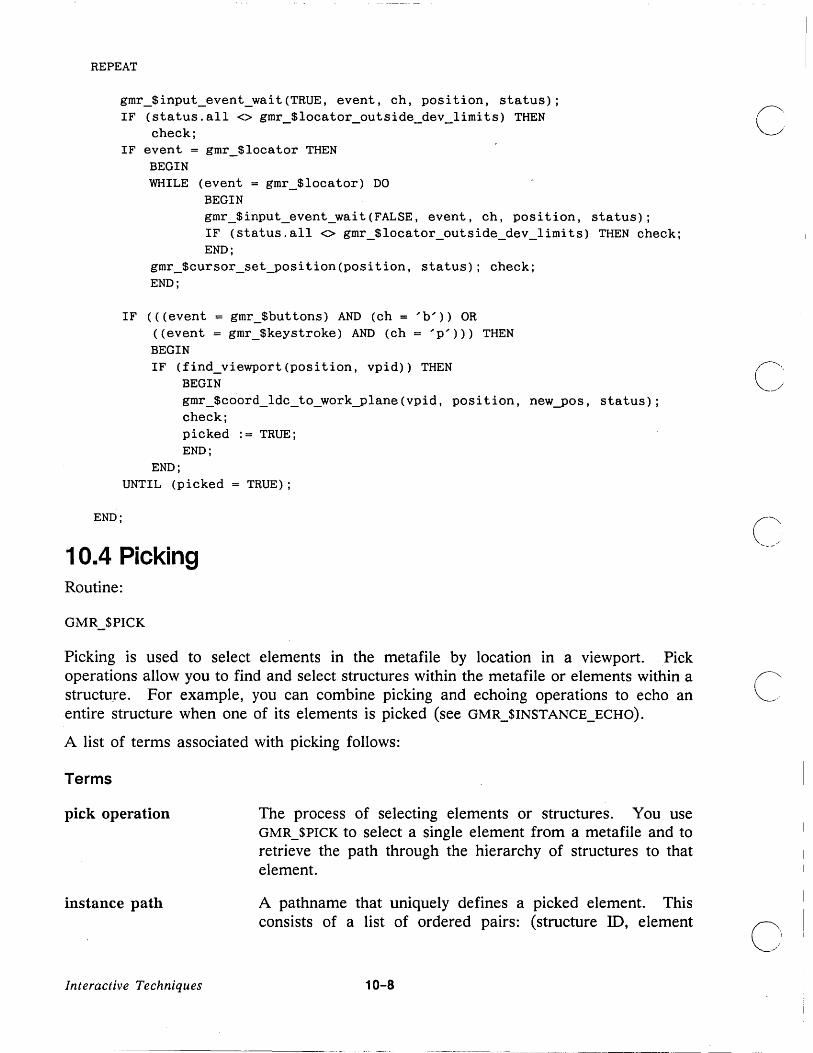
REPEAT
gmr_$input_event_wait(TRUE, event, ch, position, status); IF (status.all <> gmr_$locator_outside_dev_limits) THEN
check; IF event = gmr_$locator THEN
BEGIN WHILE (event = gmr_$locator) DO
BEGIN gmr_$input_event_wait(FALSE, event, ch, position, status); IF (status.all <> gmr_$locator_outside_dev_limits) THEN check; END;
gmr_$cursor_set_position(position, status); check; END;
IF «(event = gmr_$buttons) AND (ch = 'b'» OR «event = gmr_$keystroke) AND (ch = 'p'») THEN BEGIN IF (find_viewport (position, vpid» THEN
BEGIN
END;
gmr_$coord_ldc_to_workylane(vpid, position, newyos, status); check; picked := TRUE; END;
UNTIL (picked = TRUE);
END;
1 0.4 Picking Routine:
GMR_$PICK
Picking is used to select elements in the metafile by location in a viewport. Pick operations allow you to find and select structures within the metafile or elements within a structure. For example, you can combine picking and echoing operations to echo an entire structure when one of its elements is picked (see GMR_$INSTANCE_ECHO).
A list of terms associated with picking follows:
Terms
pick operation
instance path
Interactive Techniques
The process of selecting elements or structures . You use GMR_$PICK to select a single element from a metafile and to retrieve the path through the hierarchy of structures to that element.
A pathname that uniquely defines a picked element. This consists of a list of ordered pairs: (structure ID, element
10-8
c
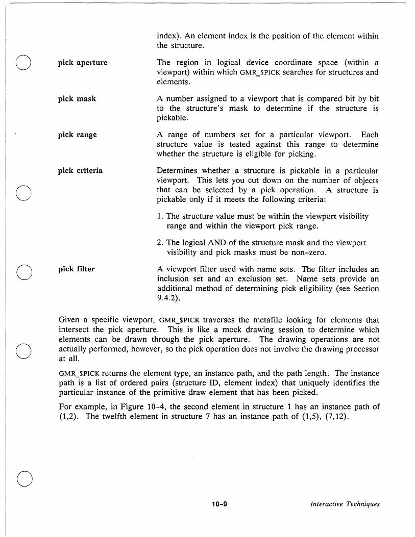
o
o
o
pick aperture
pick mask
pick range
pick criteria
pick filter
index). An element index is the position of the element within the structure.
The region in logical device coordinate space (within a viewport) within which GMR_$PICK searches for structures and elements.
A number assigned to a viewport that is compared bit by bit to the structure's mask to determine if the structure is pickable.
A range of numbers set for a particular viewport. Each structure value is tested against this range to determine whether the structure is eligible for picking.
Determines whether a structure is pickable in a particular viewport. This lets you cut down on the number of objects that can be selected by a pick operation. A structure is pickable only if it meets the following criteria:
1. The structure value must be within the viewport visibility range and within the viewport pick range.
2. The logical AND of the structure mask and the viewport visibility and pick masks must be non-zero.
A viewport filter used with name sets. The filter includes an inclusion set and an exclusion set. Name sets provide an additional method of determining pick eligibility (see Section 9.4.2).
Given a specific viewport, GMR_$PICK traverses the metafile looking for elements that intersect the pick aperture. This is like a mock drawing session to determine which elements can be drawn through the pick aperture. The drawing operations are not actually performed, however, so the pick operation does not involve the drawing processor at all.
GMR_$PICK returns the element type, an instance path, and the path length. The instance path is a list of ordered pairs (structure ID, element index) that uniquely identifies the particular instance of the primitive draw element that has been picked.
For example, in Figure 10-4, the second element in structure 1 has an instance path of (1,2). The twelfth element in structure 7 has an instance path of (1,5), (7,12).
10-9 Interactive Techniques

Structure 1: car
Element 1: attribute
Element 2: polyline
Element 5: wheel instance (structure 7)
Last Element
Structure 7: wheel
Element 1: spoke 1 (polygon)
Element 12: spoke 12 (polygon)
Last Element
Figure 10-4. Two Structures for Picking
10.4.1 Picking Methods
Routines:
GMR_$PICK_SET_METHOD GMR_$PICK_INQ_METHOD GMR_$VIEWPORT_SET_PATH_ORDER GMR_$VIEWPORT_INQ_PATH_ORDER
Currently, there is only one pick methods: pick the nth element that crosses the pick aperture and also satisfies the pick criteria.
GMR_$PICK_SET_METHOD sets the pick method for a specified viewport.
GMR_$PICK_INQ_METHOD returns the current pick method of a specified viewport.
You can set the order of the instance path returned by GMR_$PICK. Two methods are supported: top-first (picked element last) and bottom-first (picked element first). The (~ .... default is top-first. ~
GMR_$VIEWPORT_SET_PATH_ORDER sets the path order for a specified viewport.
GMR_$VIEWPORT_INQ_PATH_ORDER returns the current path order used in the specified viewport. This ordering is used for both picking and instance echoing.
Interactive Techniques 10-10
----------------------_ .. _-_ ......... _ ... _.
c

o
o
o
o
Example - Returning an Instance Path The syntax for GMR_SPICK is the following:
GMR_$PICK (vpid, center, pick_index, pick_data_size, pick_data, status)
INPUT PARAMETERS
vpid
center
Identifies the viewport, in GMR_SVIEWPORT_ID_T format. This is a 2-byte integer.
Is the center of the pick aperture, in GMR_SF3_POINT_T format. This is a point in logical device coordinates that is usually supplied from locator input (for example, a mouse or touchpad).
Defines n. The nth element that crosses the pick aperture and also satisfies the pick criteria is selected. This is a 4-byte integer. The value of n is usually 1. Note that the current pick method is used.
pick_data_size Is the size in bytes of the output record pick_data. This is a 4-byte integer.
OUTPUT PARAMETERS
pick_data Is a variable length record, in GMR_SPICK_DATA_T format. It contains the following information:
element_type The type of element that was picked, in gmr_$element_type_t format This parameter is a 2-byte integer.
pick yath _depth The length of the pick path, in gmr_$instanceyathlength_t format. This is the number of levels to the picked element. This parameter is a 2-byte integer. If pick_data_size indicates that the pick_data is not large enough, 3D GMR only returns as much data as will fit.
pickyath The path of the picked element, in gmr _ $instance yath _ t format. This parameter is an array of records specified as a list of (structure ill, element index) pairs.
10-11 Interactive Techniques

Refer to the Data Types Section (Chapter 1) of DOMAIN 3D Graphics Metafile Resource Call Reference for information on how to build this record. ~
status Completion status, in STATUS_$T format. This data type is 4 bytes long.
This fragment uses the two structures illustrated in Figure 10-5.
Structure 1: car
Element 1: attribute
Element 2: polyline
Element 5: wheel instance (structure 7)
Last Element
Structure 7: wheel
Element 1: spoke 1 (polygon)
Element 12: spoke 1 2 (polygon)
Last Element
Figure 10-5. Picking Example
Assume that the operator identifies spoke 12 using a mouse button. Then the following fragment:
:= 1; pick_index pick_data_size := gmr_$pick_data_size;
GMR_$INPUT_EVENT_WAIT (TRUE , event, ch, center, status); GMR_$PICK (vpid, center, pick_index, pick_data_size, pick_data, status);
returns the following information:
element type = polygon path length = 2 instance path = 1,5
7,12
Interactive Techniques
level 1 level 2
10-12
f' \ '-_ .. ,
c'

o
o
o
o
o
10.4.2 Limiting the Pick Search
There are three ways to limit the pick search:
1. Modifying the pick aperture
2. Setting the pick mask and pick range
3. Using name sets
Modifying the Pick Aperture Routines:
GMR_$PICK_SET_APERTURE_SIZE GMR_$PICK_INQ_APERTURE_SIZE GMR_$PICK_INQ_CENTER
The search for structures or elements is limited to a specified range of logical device coordinates, called the pick aperture (see Figure 10-6). The aperture is specified in terms of height, width, depth, and center. The center is the point returned from the last GMR_$PICK routine. GMR_$PICK searches for structures or elements that fall into the following region:
(center.x - 0.5*width to center. x + 0.5*width, center.y - 0.5*height to center.y + 0.5*height, center.z - O.5*depth to center.z + 0.5*depth)
T Height
y
~~-" -~
Figure 10-6. Pick Aperture
- Default Pick Center
Use GMR_$PICK_SET_APERTURE_SIZE to define the pick aperture for a specified viewport. The pick aperture is initialized to center (0.0, 0.0, 0.0) in logical device coordinates. The
10-13 Interactive Techniques

default depth is 1 which allows picking within the entire depth of the default viewport. The default height and width is 0.1.
C~· GMR_$PICK_INQ_APERTURE_SIZE returns the width, height, and depth of the pick aperture .-/ in a specified viewport.
GMR_$PICK_INQ_CENTER returns the center point from the last pick operation on the specified viewport.
Setting the Viewport Pick Mask and Pick Range Routines:
GMR_$VIEWPORT_SET_PICK GMR_$VIEWPORT_INQ_PICK
The above routines set and return the viewport pick mask and pick range . You can assign a mask and a value to each structure using GMR_$STRUCTURE_SET_ VALUE_MASK (see Chapters 2 and 9). The structure value and mask are used to set visibility and picking (" eligibility. At display time, the structure value and mask are compared as follows: ',-., ,
• The structure value is compared against the viewport visibility range and viewport pick range
• The structure mask is compared against the viewport visibility mask and the viewport pick mask.
A structure is pickable only if it meets the following criteria:
1. The structure value must be within the viewport visibility range and within the viewport pick range.
2. The logical AND of the structure mask and the viewport visibility and pick masks must be non-zero.
If both of these criteria are true, the structure is pickable even though it may not be (' visible on the screen. This means that you can pick an invisible object without redrawing ~ __ it as follows: change the viewport visibility range and mask to match the viewport pickability range and mask and then pick the structure.
The default is that all structures are pickable.
GMR_$VIEWPORT_SET_PICK sets the pick range and pick mask for a viewport.
GMR_$VIEWPORT_INQ_PICK returns the pick range and pick mask of a viewport.
Refer to the visibility examples in Section 9.5 for more information on using these routines. You can use pick range and pick mask values the same way that you use visibility range and visibility mask values.
Interactive Techniques 10-14

,",,\ u
o
o
o
o
Using Namesets to Set Pick Eligibility for Primitives Routines:
GMR_$VIEWPORT _SET _PICK_FIL TER GMR_$VIEWPORT _INQ_PICK_FIL TER
Primitive pick eligibility can be controlled using the name set add and replace routines (see Chapter 4). At display time, the current name set is compared to the viewport's pick filter. The pick filter consists of an inclusion list and an exclusion list. In order to be pickable, a primitive (or structure) must meet both the visibility and the pickable criteria.
The relationship between the inclusion set, the exclusion set, and the current name set is stated in Figure 10-7.
Ii = Viewport invisibility inclusion set Ei = Viewport invisibility exclusion set Ip = Viewport pick inclusion set Ep = Viewport pick exclusion set N = Current name set int = Set intersection
1. For a primitive within a visible structure to be visible: Either all names in the current name set must be absent from the viewport invisibility inclusion set or at least one name must be in the viewport invisibility exclusion set.
Visible <=> ( Ii int N = 0 ) OR ( Ei int N I:. 0 )
2. For a primitive within a visible structure to be invisible: At least one name in the current name set must be in the viewport invisibility inclusion set and all names in the name set must be absent from the viewport invisibility exclusion set.
Invisible <=> ( Ii int N I:. 0 ) AND ( Ei int N = 0 )
3. For a primitive to be eligible for picking: The visibility criteria must be met (number 1 above) and at least one name in the current name set must be in the viewport pick inclusion set and all names in the name set must be absent from the viewport pick exclusion set.
Pickable <=> [( Ii int N = 0 ) OR ( Ei int N I:. 0 )] AND ( Ip int NI:. 0 ) AND
( Ep int N = 0 )
Figure 10-7. Name Set Visibility and Pick Criteria
10-15 Interactive Techniques

GMR_$VIEWPORT_SET_PICK_FILTER sets the inclusion and exclusion name set lists for picking eligibility. An element is eligible for picking only if its name set is in the inclusion list and not 'in the exclusion list. C GMR_$VIEWPORT_INQ_PICK_FILTER returns the inclusion and exclusion name set lists for picking eligibility.
Pick eligibility based on structure value and mask takes precedent over name set pick eligibility.
In order to be pickable, a primitive must meet both the visibility and the pick criteria. This does not mean that the primitive must be displayed on the screen. To pick an invisible object, you can change the name set and then pick it without actually calling a viewport clear/refresh combination.
Refer to the discussion and example in Section 9.4.
1 0.5 Echoing Echoing is a means of visually differentiating elements or subtrees of interest from all others. You can acheive this visual signal in two ways:
1. Redraw the element or subtree with a different color or line style. For this purpose the 3D GMR package provides a highlighting attribute block that overrides attributes set by individual attribute elements or other attribute blocks.
Redrawing the element or structure with a different line style is a particularly useful echo method for monochrome nodes.
2. Draw a box around the structure that contains the picked element or subtree. This method uses the bounding box associated with each structure. For more information on bounding boxes, see Chapter 13.
You can specify echoing in selected viewports or specify a different type of echoing in different viewports.
An echo lasts only until the next viewport clear/refresh operation. An echo may result in an incorrect picture since the echoed object is redrawn over existing geometry.
10.5.1 Pick Echo and Instance Echo
3D GMR defines two types of echoing: pick echo and instance echo.
Pick Echo Routines:
GMR_$PICK_SET_ECHO_METHOD GMR_$PICK_INQ_ECHO_METHOD
Interactive Techniques 10-16
c
C I
I
I i

o
o
o
o
o
Pick echo is the 3D GMR package response to a pick operation. It provides visual confirmation that a pick operation has been performed. This method allows you to echo the primitive draw element at the end of the instance path.
GMR_$PICK_SET_ECHO_METHOD sets the pick echo method for a particular viewport. You can use the highlighting attribute block method, the bounding box method, or turn pick echoing off (default). When pick echo is in effect, the element at the end of the picked instance path is automatically echoed.
GMR_$PICK_INQ_ECHO_METHOD returns the current pick echo method for a specified viewport.
Instance Echo Routines:
GMR_$INSTANCE_ECHO GMR_$INSTANCE_ECHO_SET_METHOD GMR_$INSTANCE_ECHO_INQ_METHOD
An instance echo uses an application supplied instance path to identify the echoed object. Instance echo gives the application a means of customizing the echo, functionality. It can be used as an echo to an application pick d~vice rather than the 3D GMR geometric pick device. For example, an application can choose to echo all objects with a certain property (i.e., size, price, etc.). The application can generate the path and then pass it to the echo instance echo routine, GMR_$INSTANCE_ECHO.
Instance echo has the added feature of path depth. By specifying a path depth, you can indicate how far down the path to begin echoing. In this way you can echo a single element or an entire subtree.
GMR_$INSTANCE_ECHO echos an element or a subtree of an application-supplied instance path in a specified viewport.
GMR_$INSTANCE_ECHO_SET_METHOD sets the instance echo method for a particular viewport. As with pick· echo, you can use either the highlighting attribute block method or the bounding box method. The default is the bounding box method.
GMR_$INSTANCE_ECHO_INQ_METHOD returns the instance echo method of a particular viewport.
10.5.2 Setting the Highlighting Attribute Block
Routines:
GMR_$VIEWPORT .... SET_HILIGHT_ABLOCK GMR_$VIEWPORT_INQ_HILIGHT_ABLOCK
GMR_$VIEWPORT_SET_HILIGHT_ABLOCK assigns a particular attribute block to a viewport. You identify the attribute block by using its ablock identification number.
10-17 Interactive Techniques

GMR_$VIEWPORT_INQ_HILIGHT_ABLOCK returns the identification number of the current "highlighting attribute block for a particular viewport.
Example - Setting a Highlight Attribute Block and Initializing Picking All of the following fragments are from Sample3 (see Appendices A, B, and C).
This fragment initializes an ablock (ablock4) to be used for highlghting. The routines in the fragment set the line color to 5 and intensity 1.0. The fragment also sets the pick path order, echo method, and pick aperture.
PROCEDURE inityicking; VAR
i := integer;
BEGIN
gmr_Sablock_create(gmr_Snochange_ablock, ablock4, status); gmr_Sablock_set_line_color(ablock4, 5, gmr_Sset_value_and_enable,
status); gmr_Sablock_set_line_inten(ablock4, 1.0, gmr_Sset_value_and_enable,
status);
FOR i := 1 TO num_views DO BEGIN
END;
gmr_Sviewport_set_path_order(view_vpid[i], gmr_Stop_first, status); gmr_Sinstance_echo_set_method(view_vpid[i], gmr_Selement_hl_bbox,
status) ; gmr_Sviewport_set_hilight_ablock(view_vpid[i], ablock4, status); gmr_Spick_set_aperture_size(view_vpid[i], 0.01, 0.01, 2.0, status);
Example - Picking and Echoing This fragment picks a structure (given a point). It echos the structure picked using the current echo technique (bounding box or ablock). The value of "level" is determined from the procedure named do_button that follows this fragment.
PROCEDURE pick(IN position: gmr_Sf3_point_t);
VAR pick_vpid pick_index pick_data
BEGIN pick_index := 1;
gmr_Sviewport_id_t; integer32; gmr_Spick_data_t;
IF (find_viewport (position, pick_vpid) = FALSE) THEN RETURN;
c
IF (no_lastyick = FALSE) THEN I
display_viewport(last_hl_vp); 0
Interactive Techniques 10-18

u
o
o
o
o
gmr_$pick_(pick_vpid, position, pick_index, gmr_$data_size, pick_data, status) ;
IF «status.all <> gmr_$pick_path_empty) AND (status.all <> gmr_$operation_invalid» THEN BEGIN
END;
check; gmr_$instance_echo(pick_vpid, level, pick_data. pick_path , status); check; no_last_pick := FALSE; last_hl_vp := pick_vpid; cur_pick-path := pick_data. pick_path; cur_level .- level; END;
Example - Acting on a Menu Item This fragment uses several of the routines discussed in this chapter. This fragment includes a case on the button picked and performs the appropriate actions. The routines included change the work plane, set the echoing technique, and change the level of picking. If the viewport is to be refreshed, the display_flag is set to true. If the user picks exit, the end_flag is set to true.
PROCEDURE do_button(IN menu_item: integer; OUT end_flag: boolean);
VAR i clock new_pos
BEGIN
integer; time_$clock_t; gmr_$f3-point_t;
clock. low := 125000; clock. high := 0;
end_flag := FALSE;
CASE menu_item OF
1: { Display a new teapot. } new_teapot;
2: { Change the work plane. BEGIN display_message(3); get_position(new_pos); FOR i := 1 TO num_views DO
gmr_$coord_set_work_plane(view_vpid[i], new_pos, tea_normal[i], status); check;
10-19 Interactive Techniques

END;
3: { Move the structure/element to a new location. } IF (no_last_pick) THEN
display_message (4) ELSE
BEGIN display_message(2); get-position(new_pos); move (new_pos) ; END;
4: { Delete an element/structure. } IF (no_last_pick) THEN
display_message (4) ELSE
delete;
5: { Echo with a bounding box. } BEGIN FOR i := 1 TO num_views DO
BEGIN gmr_$instance_echo_set_method(view_vpid[i], gmr_$element_hl_bbox,
status); check; END;
time_$wait(TIME_$RELATIVE, clock, status); check; END;
6: { Highlight with a different color. } BEGIN FOR i := 1 TO num_views DO
BEGIN gmr_$instance_echo_set_method(view_vpid[i], gmr_$element_hl_bbox,
status); check; gmr_$viewport_set_hilight_ablock(view_vpid[i] ,
gmr_$element_hl_ablock, status); check; END;
time_$wait(TIME_$RELATIVE, clock, status); check; END;
7: { Allow picking at level 1 (i.e., entire teapot). } BEGIN ievel := 1; time_$wait(TIME_$RELATIVE, clock, status); check; END;
8: { Allow picking at level 2 (i.e., base or top). } BEGIN level := 2; time_$wait(TIME_$RELATIVE, clock, status); check; END;
Interactive Techniques 10-20
~ \
..... _--- ..
c:
o
-- ----.... -.... -------~----------------- .. -------- -~~~ -------

END;
C)
o
o
9: { Allow picking at level 3 (i.e., pot, spout, handle or cover, knob).} BEGIN level := 3; time_$wait(TIME_$RELATIVE, clock, status); check; END;
10: { Exit. end_flag .- TRUE;
END; {case}
10-21 Interactive Techniques

c
('-~ ,
...... _- ~.
I
C

o
C)
0
o
Chapter 11
Editing Metafiles
3D GMR has several functions for efficient editing of files. These functions allow you to insert, delete, and replace elements and structures easily. Pick operations provide ready access to the structures and elements that you want to edit (see Chapter 10).
11.1 Structure Editing A structure is eligible for the following operations:
Create
Open
Erase
Delete
Copy
Set name
Creates an empty structure, assigns it an identification number, and (optionally) assigns a unique name.
Prepares a structure for editing operations .and optionally creates a backup version.
Deletes all elements leaving an empty structure.
Completely eradicates a structure.
Copies the contents of one structure into another.
Changes the name of a structure.
To edit an instanced structure, you must open the instanced structure. You cannot edit an instanced structure from an instancing structure.
11-1 Editing Metafiles

GMR_$STRUCTURE_INQ_COUNT returns the number of structures in the metafile and a C number guaranteed to be greater than or equal to the largest structure number. You can . ./,1
then examine every structure by checking structure numbers from 0 to the maximum value (0 is used).
11.2 Element Editing Routines:
GMR_$INQ_ELEMENT_TYPE GMR_$ELEMENT_SET_INDEX
GMR_$ELEMENT_INQ_INDEX
An element is eligible for the following operations:
Delete Deletes an element.
Insert Inserts an element after the current element.
Replace Replaces an element with another element.
Inquire Inquires the element type and other element parameters.
GMR_$INQ_ELEMENT_TYPE returns the type of the current element in the current open structure. Refer to the DOMAIN 3D Graphics Metafile Resource Call Reference for more information on this routine.
In addition, you can set and inquire the element index.
An element index is used to keep track of elements within a structure. An element index is like a line number in a text file. It positions you within a file so that you can edit individual elements. The following rules apply when you use the element index for editing:
1. To inquire or read back the nth element, set the index to n, inquire the element type, and then inquire for more information.
2. To replace or delete the nth element, set the index to n and perform the replace or delete function.
3. To insert new elements after the nth element, set the element index to nand perform the insertion function.
4. To insert new elements before the first element, set the element index to 0 and perform the insertion function. Inquiring, deleting, and replacing functions are illegal when the index is set to O.
Editing Metafiles 11-2
(~ \ '--... , '
0 1
I
---_._-_._---------_ .. - .. _ .. _--

·u Except for the special case noted in 4 above, refer to an element by setting the element index to the current element.
When you open a structure, the element index is set to 0 by default.
GMR_$ELEMENT_INQ_INDEX returns the current element index.
GMR_$ELEMENT_SET_INDEX sets the element index to a specified value.
11.3 Insert and Replace Modes Insert and replace modes are two distinct modes in which the element insertion routines operate.
o 11.3.1 Insert Mode
o
o
o
In the 3D GMR package, insert mode is the default. Each time you call an element insertion routine, a new element is inserted after the current element. The new element becomes the new current element and the element index is automatically incremented.
11.3.2 Replace Mode
In replace mode, the current element is deleted and the new element is put in its place. The new element becomes the current element and the element index does not change.
Routines:
GMR_$REPLACE_SET_FLAG
GMR_$REPLACE_INQ_FLAG
To replace one element with another or a parameter within an element with another, use GMR_$REPLACE_SET_FLAG. This routine instructs the 3D GMR package to continuously replace the current element. This is a useful feature when editing with dynamic feedback, such as when rubber banding a line.
GMR_$REPLACE_INQ_FLAG tells you whether the graphics metafile package is in the (default) insert state or in the replace state.
11-3 Editing Metafiles

11.4 Deleting You can delete an element or an entire structure.
11.4.1 Deleting Structures
Routine:
GMR_$STRUCTURE_DELETE
GMR_$STRUCTURE_DELETE deletes the current open structure. A structure must be open before you can delete it.
Example This fragment opens a structure and then deletes it.
gmr_$structure_open(struc_id, FALSE, status); gmr_$structure_delete(status);
Deleting Instanced Structures A structure cannot contain references to a deleted structure. Therefore, you must delete
c
all instances from containing structures before you delete the open structure. However, a (' structure that contains instances can be deleted. "'-.._.
For example, consider the following four structures:
gmr_$structure_create('bolt', 4, bolt_id, status);
gmr_$structure_close(TRUE, status);
gmr_$structure_create('washer', 6, washer_id, status);
gmr_$structure_close(TRUE, status);
gmr_$structure_create('bracket', 7, bracket_id, status);
gmr_$instance_transform(bolt_id,matl,status); gmr_$instance_transform(washer_id,matl,status); gmr_$instance_transform(bolt_id,mat2,status); gmr_$instance_transform(washer_id,mat2,status); gmr_$structure_close (TRUE , status);
Editing Metafiles 11-4
c"
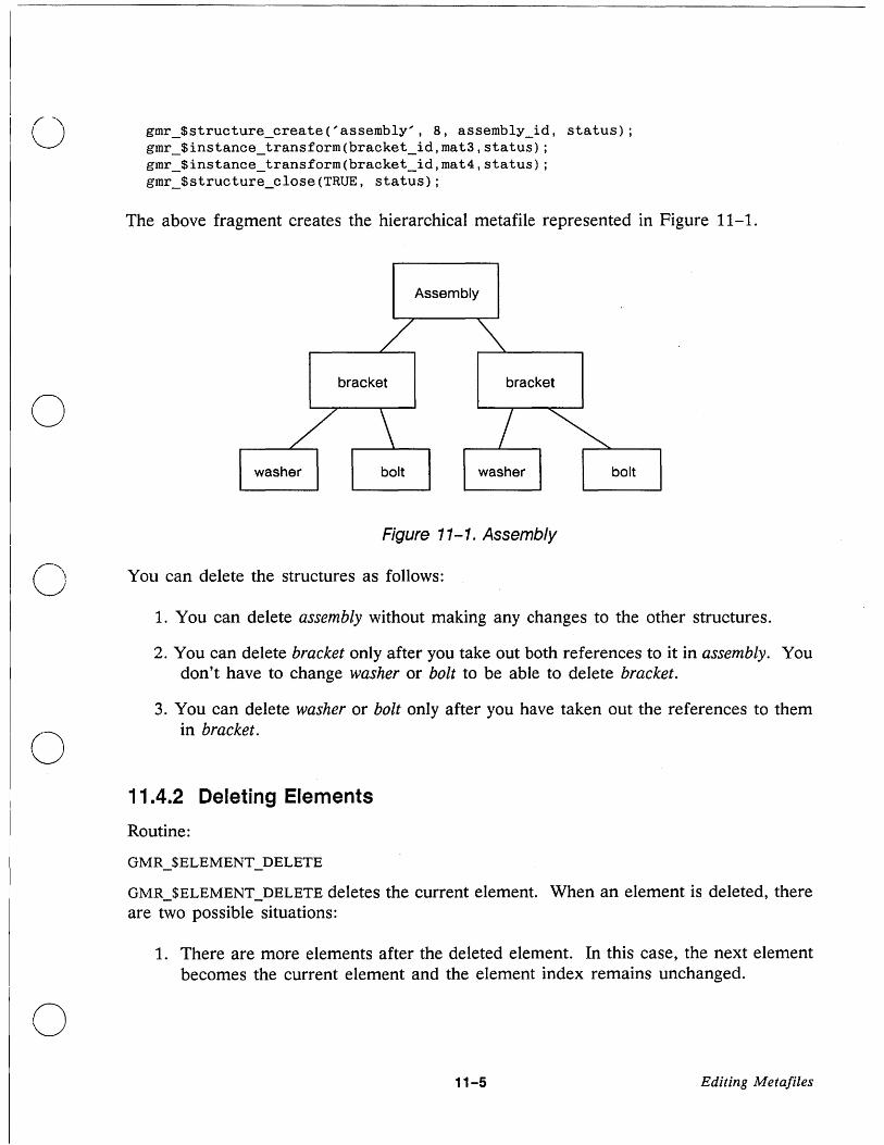
o
gmr_$structure_create('assembly', 8, assembly_id, status); gmr_$instance_transform(bracket_id,mat3,status); gmr_$instance_transform(bracket_id,mat4,status); gmr_$structure_close (TRUE , status);
The above fragment creates the hierarchical metafile represented in Figure 11-1.
Assembly
bracket bracket
washer bolt
Figure 11-1. Assembly
..--"" U You can delete the structures as follows:
o
o
1. You can delete assembly without making any changes to the other structures.
2. You can delete bracket only after you take out both references to it in assembly. You don't have to change washer or bolt to be able to delete bracket.
3. You can delete washer or bolt only after you have taken out the references to them in bracket.
11.4.2 Deleting Elements
Routine:
GMR_$ELEMENT_DELETE
GMR_$ELEMENT_DELETE deletes the current element. When an element is deleted, there are two possible situations:
1. There are more elements after the deleted element. In this case, the next element becomes the current element and the element index remains unchanged.
11-5 Editing Meta/iles

2. The deleted element was the last element in the structure. In this case, the C previous element (if any) becomes the current element and the element index is decremented.
In the second case above, 3D GMR rescans the structure from the top to find the beginning of the previous element. This can affect performance. Therefore, to delete a whole series of elements, begin with the first one that you want to delete.
When you delete the only element in the structure, the structure is empty and there is no current element. The element index is set to o.
11.5 Erasing Routine:
GMR_$STRUCTURE_ERASE
GMR_$STRUCTURE_ERASE deletes all elements in the current structure and leaves the structure open so that you may insert new elements.
Example This fragment opens a structure, erases all elements within it, and then closes the structure.
gmr_$structure_open(struc_id, FALSE, status); gmr_$structure_erase(status); gmr_$structure_close (TRUE , status);
11.6 Copying Routine: GMR_$STRUCTURE_COPY
( '" /'
GMR_$STRUCTURE_COPY copies the entire contents of another structure into the current C-.''' ..... open structure. The specified structure is copied into the current open structure after the current element. The element index is then set to the last copied element.
Example The following fragment creates a new structure named newcopy that is an exact copy of an existing structure. The identification of the existing structure is "source_seg_id".
gmr_$structure_create('newcopy', 7, structure_id, status); gmr_structure_copy(file_id, source_seg_id, status); gmr_$structure_close(TRUE, status)
You can use the file_id argument in GMR_$STRUCTURE_COPY to copy a structure from one file to another file. However, structures containing instance elements cannot b_e copied from one file to another.
Editing MetaJiles 11-6

o
o
o
o
o
Note the difference between GMR_$STRUCTURE_COPY and GMR_$INSTANCE_TRANSFORM
GMR_$STRUCTURE_COPY leaves you with two copies of the structure, allowing you to modify the two copies separately. GMR_$INSTANCE_TRANSFORM leaves you with one copy of the structure and a reference to that structure, so that all displayed instances can be changed by modifying the single instanced structure.
11.7 Reflecting Editing Changes There are two ways to reflect editing changes:
1. Set the viewport refresh state.
2. Use dynamic mode.
11.7.1 Viewport Refresh States
Routines:
GMR_$VIEWPORT_SET_REFRESH_STATE
GMR_$VIEWPORT_INQ_REFRESH_STATE
There are four viewport refresh states:
Refresh inhibit The viewport is rewritten GMR_$VIEWPORT_REFRESH.
when you call
Refresh wait The viewport is rewritten when you call
Refresh update
Refresh partial
GMR_$VIEWPORT_REFRESH or GMR_$DISPLA Y_REFRESH.
The viewport is refreshed every time a change is made to the metafile.
Individual elements are updated as they are changed in the metafile.
Use refresh inhibit and refresh wait when you do not want editing changes reflected in the display (for example, for increased speed when editing a metafile).
Refresh update is a relatively slow but exact update method. The entire displayed structure is reprocessed. Use this technique when you want to reflect changes made to the metafile (for example, when inserting a new element). The entire viewport is not necessarily affected. If you use hierarchical structures, you can restrict the update to a small area of the screen.
11-7 Editing Metafiles

Refresh partial is a faster but inexact method. An element is deleted by erasing it (that is C' drawing it in the background color). A new element is inserted by drawing it without regard to other elements already drawn on the display.
An element is replaced either by erasing and redrawing it without regard to other elements, or by using an XOR raster operation. The replacement method is selected using the routine GMR_$DYN_MODE_SET_DRAW_METHOD (see Section 11.7.2).
If the element is an instance element, then the entire subtree is redrawn.
GMR_$VIEWPORT_SET_REFRESH_STATE sets the refresh state of a viewport.
GMR_$VIEWPORT_INQ_REFRESH_STATE returns the refresh state of a viewport.
11.7.2 Dynamic Mode
Routines
GMR_$DYN_MODE_SET_DRA W _METHOD
GMR_$DYN_MODE_SET_ENABLE
GMR_$DYN_MODE_INQ_DRA W _ENABLE
GMR_$DYN_MODE_INQ_ENABLE
Dynamic mode is an option within partial refresh mode that allows you to change a single element repeatedly with fast, relatively clean, refreshing of the screen. Use this technique ~~
when a fast redrawing capability is required in between major change to a metafile (for (\--____ . example, when rubber-banding a line).
Dynamic mode works on one element. If the element is an instance element, then the entire subtree is redrawn. The element is identified by an instance path. The path is a list of (structure ID, element index) pairs that uniquely defines a particular element. The path can be retrieved by GMR_$PICK or can be an application-supplied path.
GMR_$DYN_MODE_SET_ENABLE turns the dynamic mode on and off for viewports that are in partial-refresh state.
GMR_$DYN_MODE_SET_DRAW_METHOD sets the redraw method that will be used when a viewport is in partial-refresh state or when dynamic mode is enabled. There are two different dynamic drawing modes:
Redraw
XOR
Each subsequent redraw operation erases the enabled· element to the background color and then redraws the element in the new position. This is done without regard for other elements on the screen.
I
Editing Metafiles
Uses the XOR raster operation to erase the enabled element and and draw the new version. The background color is
11-8
C l
I
I

o
o
o
o
preserved but the redrawn element may have pixels turned off when overlapped with other geometry.
GMR_$DYN_MODE_INQ_DRA W _METHOD returns the type of dynamic drawing that is enabled for either viewports in partial refresh states or in dynamic mode.
GMR_$DYN_MODE_INQ_ENABLE tells whether a dynamic mode is enabled and if so, returns the path, path depth, and path order.
11-9 Editing Metafiles

C, ~'

o
o
Chapter 12
Using Color
There are three basic methods for using color with the 3D GMR package:
1. Use the default color binding.
2. Modify portions of the color binding using linear interpolation of application supplied specified colors.
3. Modify portions of the color binding using an application specified map.
The first method is described in Chapter 4. This Chapter describes the second two methods.
o 12.1 3D GMR Color
o
3D GMR uses several parameters to specify color (color values, color map indices, color identification numbers, and intensity values). These parameters are defined and used as follows:
• A metafile contains attributes that specify color IDs and intensities.
• Each color ID corresponds to a range of one or more color map indices. When there is more than one, then there is an "intensity minimum" and an "intensity maximum" associated with the extremes of the range.
12-1 Using Color

• Each color map index corresponds to a value in the color map. A value can be established with either a red-green-blue (RGB) triplet or a hue-saturation-value (HSV) triplet (see Section 12.2). C
When a primitive has a color ID attribute that corresponds to a single color map index, then that index is used to draw that primitive. When a primitive has a color ID attribute that corresponds to a range of color map indices, then the intensity attribute of the primitive determines which color map index is used.
The 3D GMR package allows you to set color in two stages. The first stage is to include color attribute elements (color ID and intensity) in the metafile for particular modeling elements, such as polygon and polyline. The second stage is to establish how the color ID and intensity are translated to draw values by calling a set of color routines. This latter process is called binding the colors to draw values and is performed at display time.
12.2 Color 10 and Intensities Routines:
GMR_SCOLOR_SET_RANGE
GMR_SCOLOR_INQ_RANGE
A color indentification number (color ID) is an integer between 0 and GMR_SMAX_COLOR_ID, where GMR_SMAX_COLOR_ID is at least 255.
An intensity is a floating-point value between 0 and 1. The value is used to select a single color from the collection of colors associated with a color ID by means of its color binding. This selection resolves the color ID/intensity pairs to set color map indices at display time.
Color binding has two steps:
1. Associate a color ID with a starting color map index and a range of color map indices. This establishes the 3D GMR color range table. One routine performs this function:
GMR_SCOLOR_SET_RANGE
2. Set the color map values for each color map index. Use one of the following routines to set the color map values:
GMR_SCOLOR_DEFINE_HSV GMR_SCOLOR_DEFINE_RGB GMR_SCOLOR_SET_MAP
The 3D GMR color range table is established with calls to GMR_SCOLOR_SET_RANGE.
Each call to this routine establishes an entry in the 3D GMR color range table for the input color ID. For each color ID, there is a starting color map index and a range. The range, which must be at least one, is the number of consecutive color map indices associated with the color ID. The intensity selects a single color froIn the collection of colors associated with the color ID. An intensity value of 1 sets the draw value to the
Using Color 12-2
c'

o
0
.---",\ ( I '-.-/
o
o
highest color map index in the range. An intensity of 0 sets the draw value to the lowest color map index in the range.
For example, suppose a color ID maps to four different color map indices as shown in Figure 12-1. If a primitive has a color ID attribute of 5 and an intensity attribute value of 0.2, then the smallest color map index belonging to color ID 5 (in this case 20) is used to draw the primitive.
The following routine sets the range specified in Figure 12-1:
Start
Range
Color 10 = 5l a 1 2 5 255
Color Range Table Modified by GMR_SCOLOR_SET _RANGE
20 21 22 23
0.0 ~ Inten < 0.25
0.25 s: Inten < 0.5
0.5 ~ Inten < 0.75
0.75 s: Inten ~ 1.0
Color Map
Modified by ,GMR_SCOLOR_DEFINE_RGB
or GMR_$COLOR_DEFINE_H.SV
or GMR_SCOLOR_SET _MAP
Figure 12-1. Setting the C%r Binding
12-3 Using Color
Refer to Tables 12-1 through 12-7 in Section 12.5 for the default color maps and range tables for single- and double-buffered modes.
GMR_$COLOR_SET_RANGE accepts a color ID number, a start index in the color map, and C a range which is the number of contiguous color map indices to associate with the color ID. Because this is a display-time routine, reallocation of the colors does not require editing of the metafile. This allows application programs to trade off having many colors with coarse intensity interpolation against having few colors with very smooth intensity interpolation.
GMR_$COLOR_INQ_RANGE accepts a color ID and returns the starting color map index and the range of color map indices values for the color ID.
12.3 Using RGB and HSV Color Models Routines:
GMR_$COLOR_DEFINE_HSV
GMR_$COLOR_DEFINE_RGB
GMR_$COLOR_INQ_HSV
GMR_$COLOR_INQ_RGB
GMR_$COLOR_RGB_TO_HSV
GMR_$COLOR_HSV _TO_RGB
3D GMR supports two color models: red-green-blue (RGB) and hue-saturation-value (HSV). GMR_$COLOR_DEFINE_RGB and GMR_$COLOR_DEFINE_HSV are used to change the color map. GMR_$COLOR_RGB_TO_HSV and GMR_$COLOR_HSV_TO_RGB are utility routines that convert between the two models and do not change the color map.
GMR_$COLOR_DEFINE_RGB and GMR_$COLOR_DEFINE_HSV establish the color map values using linear interpolation. These two routines differ only in the color model, that is, red-green-blue and hue-saturation-value, respectively.
A modified color map is sent to the display device when an action causes a viewport to be updated. For example, a call to a routine to clear the viewport causes a· modified color map to be loaded automatically if the viewport refresh state is in update mode.
GMR_$COLOR_DEFINE_HSV updates the section of the color ·map that corresponds to the input color ID using the hue, saturation, and value color model. The range-of -color map indices are linearly interpolated between the two input colors. Saturation and value must both be between 0 and 1. Hue is not restricted in this way because the fractional extraction takes place after the linear interpolation, if any. The fractional part of the hue is used to determine the hue (see Figure 12-2).
Using Color 12-4
(' ~-. .-'

o
o
o
o
o
1.0 red
5/6 magenta /"
1/3 green
Figure 12-2. The Fractional Part of Hue
Red has a hue of 0, green has a hue of 1/3, and blue has a hue of 2/3, and a hue of 1 is also red. For example, if value = 1 and saturation = 1, varying the hue from 2/3 to 4/3 changes the color from blue to magenta to red to yellow to green.
A saturation of 0 gives white, and a saturation of 1 yields the "pure" hue. For example, if hue = 0 and value = 1, then varying the saturation from 0 to 1 changes the color from' white to pink to red.
A value of 0 gives black, and a value of 1 gives a bright color. For example, if saturation = 0, then regardless of the hue, varying the value from 0 to 1 changes the color from black to gray to white.
GMR_$COLOR_INQ_HSV returns the hue, saturation, and values at the low and high extremes of the range for a color ID. Ambiguities can occur for gray colors.
GMR_$COLOR_DEFINE_RGB updates the section of the color map that corresponds to the input color ID by specifying the amounts of red, green, and blue (all between 0 and 1). The range of color map indices is linearly interpolated between the two input colors.
GMR_$COLOR_INQ_RGB returns the red, green, blue fraction at the low and high extremes of the range for a color ID.
GMR_$COLOR_HSV _TO_RGB translates a color specification with hue, saturation, and value to a color specification with red, green, and blue.
GMR_$COLOR_RGB_TO_HSV translates a color specification with red, green, and blue to a color specification with hue, saturation, and value. This translation is ambiguous for colors that are shades of gray from black to white as these values are independent of hue. In these cases, the returned value always has hue of 0 (Red) and a saturation of O.
12-5 Using Color

Examples
The following examples illustrate color binding.
Example 1 The following fragment sets reference draw values in the color map shown in Figure 12-3. The same range is used as in Figure 12-1.
Color Map
20 21 22 23
... Color 10 = 5
Figure 12-3. C%r Binding
This fragment sets the starting index and the range:
GMR_$COLOR_SET_RANGE( 5, 20, 4, status );
/ \ Color ID Range
Start Index
These routines set the draw values in the color map:
e1 GMR_$RGB_COLOR_T e2 : GMR_$RGB_COLOR_T .-
0.2, 0.0, 0.0 ]; [ 1.0, 0.0, 0.0 ];
GMR $COLOR DEFINE RGB( 5, e1, e2, status ); - - - / '\
Color ID High Color
Low Color
Example 2
c
These fragments are taken from Sample3 (see Appendices A, B, and C). The first is from procedure Init. GMR_$INQ_CONFIG inquires the configuration. The value returned determines the colors that are set and the use of double-buffer mode. The number of planes that a node has determines the number of colors that are available (see Section 12.5). C~\
Using Color 12-6

()
C)
o
o
PROCEDURE init;
gmr_$inq_config(display_mode, stream_$stdout, num_of~lanes, bitmap_size, status); check;
END;
Based on the number of planes returned by the GMR_$INQ_CONFIG routine (above), colors are initialized for both single- or double-buffer modes. The following ill numbers are used:
ill 1 = text (white)
ill 2 = viewport background (dark blue-green on color, black on monochrome)
ill 3 = viewport border (bright blue-green on color, white on monochrome)
ill 4 = menu highlight (white)
ill 5 = pick echo (green on color, white on monochrome)
gmr_$rgb_color_t .gmr_$rgb_color_t .-
PROCEDURE set_colors; BEGIN IF num_of_planes > 1 THEN
BEGIN { By default, color map gmr_$color_set_range ( gmr_$color_set_range ( gmr_$color_set_range (
0.00, 0.50, 1.00 ]; 0.00, 0.25, 0.50 ];
location 7 is white, 2 I, 7, I, status); check; 4, 7, I, status); check; 5, 2, I, status) ; check;
is green. }
{ Viewport background color. This will change color map location 3. } gmr_$color_set_range ( 2, 3, I, status); check; gmr_$color_define_rgb( 2, dark_bg, dark_bg, status); check;
{ Viewport border color. This will change color map location 4. } gmr_$color_set_range ( 3, 4, 1, status); check; gmr_$color_define_rgb( 3, blue_g, blue_g, status); check; END
ELSE { Monochrome node. Make the viewport background black. }
END;
{ This does not change the color map. }
BEGIN gmr_$color_set_range (2., 0, I, status); check; END;
12-7 Using Color

12.4 Redefining the Color Map Directly Routines:
GMR_SCOLOR_SET_MAP
GMR_SCOLOR_INQ_MAP
The routines listed above are available for applications that need more than the linear interpolation of the define ROB and define HSV routines. This section describes how to update the color map directly.
You can think of the color map as a one-dimensional array of up to 256 4-byte integers. Each 4-byte integer represents a color value that uses eight bits to represent the intensity of each of the primary colors (red, green, and blue) as shown in Figure 12-4.
byte: offset field name
31 0
0: integer unused
4: integer red
8: integer green
12: integer blue
Figure 12-4. An Element of the Color Map
Red, green, and blue values are each in the range [0, 255], inclusive. Using this model, each color entry is constructed as follows:
color_vector[i] := (blue + 256(green + (256*red»);
Use GMR_SCOLOR_SET_MAP to update the color map. Supply the following information:
• A start index that represents the first color in the color map to be set.
• A range that identifies the number of contiguous color map entries to set.
• A color array in GMR_SCOLOR_ VECTOR_T format. Use the above formula to create elements in the array.
GMR_SCOLOR_SET_MAP updates the current color map. The actual transfer of the color map to the display device occurs immediately.
GMR_SCOLOR_INQ_MAP returns the values stored in the current color map.
Using Color 12-8
----------- --'-'" _ ..........
c
C~
(' \ '-.. ",

12.5 Using Double-Buffering Routines for the Display o Routines:
o
(J
o
GMR_SDBUFF _SET_MODE
GMR_SDBUFF _INQ_MODE
GMR_SDBUFF _SET_DISPLAY_BUFFER
GMR_SDBUFF _SET_SELECT _BUFFER
GMR_SDBUFF _INQ_SELECT_BUFFER
When an application rapidly changes images, the updating process can affect appearance. 3D GMR provides double buffering functions to improve the appearance of these rapid changes. Double buffering partitions the video memory into two buffers and therefore limits the number of available colors. For example, on an 8-plane system, the 3D GMR technique for double buffering allows the use of six definable colors and black and white (see Figure 12-5). On a 4-plane system, only black and white are used.
Plane 7 is Unused.
--~ Planes 4-6 are for Buffer 2.
Plane 3 is the Toggle.
Planes 0-2 are for Buffer 1.
Figure 12-5. Double-Buffer Allocation - 8 Planes
3D GMR maintains a separate color map and color range table for double buffering mode. The default single buffering mode has its own color map and color range table. This makes it possible to switch between the two modes at rendering time. Switching to or from double buffering mode is a change in the color map; hence the color map is sent to the display device at the next viewport update. This means that the colors displayed in all viewports may change because of the switch between modes.
12-9 Using Color

Calls to the routines for double buffering are ignored when a monochromatic display device is used.
GMR_$DBUFF _SET_MODE sets the current mode to single- or double-buffer mode. ~ Subsequent calls to modify the color range table or color map update the color map and ~ range for the current buffering mode only.
GMR_$DBUFF _INQ_MODE returns the current mode, which is either single- or double-buffer mode.
GMR_$DBUFF _SET_DISPLAY_BUFFER displays the indicated buffer, which is either buffer 1 or buffer 2. This call is ignored if the current mode is single buffering.
GMR_$DBUFF _SET_SELECT_BUFFER indicates which buffer is to be updated: this is either buffer 1 or buffer 2. In typical double-buffering applications, the buffer to be updated is not the buffer currently displayed. This call is ignored if the current mode is single buffering.
GMR_$DBUFF _INQ_SELECT_BUFFER tells you which buffer was selected the last time that GMR_$DBUFF _SET_SELECT_BUFFER was executed.
12.6 Default Color Maps and Range Tables The number of planes on a node determine the number of available colors. The number of colors is also dependent on whether single- or double-buffer mode is used. The Tables included in this section list the default color maps and range tables for 4 and 8-plane systems and for single- and double-buffering modes. (~
\ '--- '
Table 12-1. Single-Buffer Mode Default Color Map For 4 plane system
Color Table Index Color Value Visible Color
R G B
0 0 0 0 black 1 255 0 0 red 2 0 255 0 green 3 0 0 255 blue 4 0 255 255 cyan 5 255 255 0 yellow 6 255 0 255 magenta 7 255 255 255 white
8-15 contains Display Manager colors
c\ Using Color 12-10
--- ~--- ~~~~~-~~ ~~~-~-

o
o
o
o
o
Table 12-2. Single-Buffer Mode Default Color Map For 8 plane system .
Color Table Index Color Value Visible Color
R G B
0 0 0 0 black 1 255 0 0 red 2 0 255 0 green 3 0 0 255 blue 4 0 255 255 cyan 5 255 255 0 yellow 6 255 0 255 magenta 7 255 255 255 white
8-15 contains Display Manager colors
16-255 0 0 0 black
Table 12-3. Single-Buffer Mode Default Color Range Table (for both 4 and 8 plane systems)
Color ID Start Range
0 0 1
1 1 1
2 2 1
3 3 1
4 4 1
5 5 1
6 6 1
7 7 1
8 8 1
9 9 1
15 15 1
16-255 7 1
12-11 Using Color

Table 12-4. Double-Buffer Mode, a-Plane System, Default Color Map
c Color Table
Index Color Value Visible Color
R G B
0 0 0 0 black
1 255 0 0 red
2 0 255 0 green
3 0 0 255 blue
4 0 255 255 cyan
5 255 255 0 yellow
6 255 0 255 magenta
7 255 255 255 white
8-15 contains Display Manager colors
16-127 0 0 0 black
128 0 0 0 black
129 255 0 0 red
130 0 255 0 green
131 0 0 255 blue
132 0 255 255 cyan
133 255 255 0 yellow
134 255 0 255 magenta
135 255 255 255 white C: 136-143 0 0 0 black
144-151 same pattern as 128-135
152-159 255 0 0 red
160-167 same pattern as 128-135
168-175 0 255 0 green
176-183 same pattern as 128-135
184-191 0 0 255 blue
continued on next page
c' Using Color 12-12
------- ----------------_._-----_._--_._- - --------------------- ---

Table 12-4.(continued) Double-Buffer Mode, a-Plane System, Default Color Map
o Color Table
Index Color Value Visible Color
R G B
192-199 same pattern as 128-135
200-207 0 255 255 cyan
208-215 same pattern as 128-135
216-223 255 255 0 yellow
224-231 same pattern as 128-135
o 232-239 255 0 . 255 magenta
240-247 same pattern as 128-135
248-255 255 255 255 white
Table 12-5. Double-Buffer, a-Plane System, Default Color Range
Color ID Start. Range
0 0 1
1 1 1
2 2 1
o 3 3 1
4 4 1
5 5 1
6 6 1
7 7 1
8-255 7 1
o 12-13 Using Color

Table 12-6. Double-Buffer Mode, 4-Plane System, Default Color Map
c Color Table
Index Color Value Visible Color
R G B
0 0 0 0 black 1 255 255 255 white 2 0 0 0 black 3 255 255 255 white 4 0 0 0 black 5 0 0 0 black 6 255 255 255 white 7 255 255 255 white
8-15 contains Display manager colors
Table 12-7. Double-Buffer Mode, 4-Plane System, Default Color Range
Color ID Start Range
0 0 1
1-255 1 1
Using Color 12-14

o
o
o
o
Chapter 13
Programming Techniques
This chapter describes techniques for optimizing the performance of application packages based on 3D GMR. For users of 2D GMR, a comparison of the two graphics packages is presented. Additionally, for users of GPR, a list of known interactions when using 3D GMR routines intermingled with GPR routines is presented.
13.1 Using Tags Routines:
GMR_$TAG GMR_$TAG_LOCATE GMR_$INQ_TAG
Tags let you access a data base at a particular place. For example, you may have another data base running alongside the metafile package. You can use a tag as a pointer in a structure for accessing information in the specified data base.
Tags are used as pointers to application-specific information within the metafile. The data stored in the tag is not interpreted or otherwise used by 3D GMR.
GMR_$TAG inserts a comment into the metafile.
GMR_$TAG_LOCATE locates a comment within a specified range of structures and elements in the current metafile. The routine returns the index of the first element within
13-1 Programming Techniques

the lowest-numbered structure in which the comment is found, and a character count or C' offset into the tag.
GMR_$TAG_LOCATE uses the wildcard options of the command line parser. For a description of the command line parser, see the DOMAIN System Command Reference.
GMR_$INQ_TAG returns a requested portion of tag text and the tag-text length for the current GMR_$TAG element.
13.2 Optimizing Performance This section describes some techniques for making full use of the speed and efficiency built into the 3D GMR package.
13.2.1 Creating Hierarchical Metafiles
When you instruct 3D GJ\1R to render a metafile either for display or picking, it performs a top-down search (a traversal). Therefore, if the metafile has a top-down structure, the efficiency of the search is greatly improved. The search can disregard entire portions or subtrees of the metafile. The following is a review of some of the features affected by the hierarchy of structures:
c
• Viewing all or part of a metafile. For example, if you set up your metafile so ~,
that all text is in one subtree, you can turn off all of the text in a model by (''-_ ... setting the visibility mask of that subtree.
• Reusing structures by changing transformations (instancing). This decreases the size of the metafile and allows quick updates of objects used repeatedly.
• Echoing an entire subtree or any portion of it.
• Increasing the speed of refreshing viewports. Clipping is a time consuming part of (--, viewport refreshing. Entire subtrees can become ineligible for clipping (see "---Figures 13-1 through 13-3).
The following is a description of how the hierarchy can affect clipping, echoing, and other rendering techniques that depend on a traversal of the metafile.
Bounding Boxes The 3D GMR package automatically associates a bounding box with each structure. The bounding box includes the structure and all structures that it instances. Before a structure is rendered, its bounding box is tested against the current view volume with three possible outcomes:
Programming Techniques 13-2

o
o
o
o
o
1. Trivial reject - the bounding box lies entirely outside the view volume.
2. Trivial accept - the bounding box lies entirely inside the view volume.
3. Non-trivial - the bounding box is partly inside and partly outside the view volume.
Trivial reject and trivial accept cases do not require clipping.
Figures 13-1 through 13-3 show the relationship between performance and hierarchy.
Trivial Accept:
High Performance
Non-Trivial:
Low Performance
Figure 13-1. A Single-Structure Metafile
Figure 13-1 shows a flat metafile (only one structure). If the entire metafile is within the view volume, then high performance is maintained. However, if part of the metafile is outside the view volume, then each element in the structure must be tested to see whether it requires clipping.
13-3 Programming Techniques

structure 1
structure 2 structure 3
structure 4 structure 5
structure 7
structure 6
Figure 13-2. A Hierarchical Metafile
Figure 13-2 shows an example of a hierarchical metafile. When part of this file is outside the view volume, large portions of it are either trivial accept or trivial reject cases (see Figure 13-3).
Programming Techniques 13-4

o
o
o
o
~ Trivial Accept Viewport
Trivial Reject·
Non-Trivial
Figure 13-3. Increased Performance
Notice that in Figure 13-3, only three structures are non-trivial cases that must be tested for clipping. The performance increase is significant over that of the single-structure metafile shown in Figure 13-1.
13.2.2 Improving Rendering Performance
For fastest performance, either view on a scale selected to ensure that the bounding box of the model is within the view volume (trivially accepted), or (if closer viewing is required), use instancing to break the overall model into a number of small pieces. This ensures that in anyone view, most of the displayed geometry is in structures that can be trivially accepted (or trivially rejected if they lie entirely outside the view volume).
NOTE: You can retrieve the limits of the bounding box of a structure and its subtrees using GMR_SSTRUCTURE_INQ_BOUNDS.
13-5 Programming Techniques

Hardware VS. Software Trivial accept cases lead to even greater performance increases in software than in hardware. This is because software clipping is serial, but hardware clipping is often done at the same time as projections. In other words, each software clipping operation is done separately, and clip testing is performed each time.
Size of the Metafile Creating hierarchical metafiles can reduce the size of metafiles and therefore potentially reduce paging. This can be important for very large metafiles.
Viewing Operations For views in which only a fraction of the total scene is visible, good hierarchical grouping can greatly increase performance.
Spatial vs. Logical Hierarchy In general, grouping the hierarchy according to a spatial organization (so that structures contain elements that are close to each other) results in faster performance than grouping only by logical association.
13.2.3 Other Tips to Improve Performance
The following are additional suggestions to increase performance:
Inlib a Version of 3D GMR Tailored Specifically for Your Type of Node To use 3D GMR, you must execute an INLIB command for every process in which you want 3D GMR to run. For example:
$ INLIB /LIB/GMR3DLIB
This procedure works on any node. However, performance is improved when you use the version tailored to your node. For example:
$ INLIB
. peb
. 460
. 881
/LIB/GMR3DLIB.peb /LIB/GMR3DLIB.460 /LIB/GMR3DLIB.881
Any node equipped with a peb (performance enhancement board) . A DN460 or DN660 . Any node equipped with 68020 and 68881 processors .
Use NETSTAT -CONFIG to determine whether your node is equipped with a pep, a 68020 or a 68881. For example:
$ NETSTAT -CONFIG
Programming Techniques 13-6
------ -_._._---.. __ ._--

o Maximize the Average Length of Polylines
o
Some applications specify geometry in terms of separate vectors (polylines of length 1). This adds to the number of points that must be transformed. If two polyline vectors abut, then the point in the middle must be transformed twice. Hence, specifying geometry as long polylines results in better performance.
Use Mesh Primitives When Appropriate If you regularly create mesh-like objects, use mesh primitives. The reason for this is the same as that for using long polylines instead of many short lines. If you use separate polygons to represent mesh patches, each corner where two polygons meet is transformed twice. In the extreme case where four polygons meet at one point, each point must be transformed four times. In contrast, each point of a mesh is only transformed once.
Avoid Extreme Ratios of Drawing to Instancing As too little instancing can affect performance, too much instancing before drawing can also affect performance.
Avoid Naming Structures Unnecessarily It takes time for 3D GMR to search through the list of names to make sure the name you create is unique. For large metafiles with many names, this can affect performance. Instead of assigning a name, use the structure ID that the 3D GMR package assigns.
Use Double Buffering Double buffering greatly improves the appearance of updating for operations such as zoom, rotate, and scroll. Instead of redrawing an object line by line, updating is done in a separate buffer and the entire picture is displayed at once. No performance penalties are associated with double buffering; it does, however, cut down on the number of colors that you can use.
o 13.3 3D GMR Restrictions and Limitations
o
The following limitations and restrictions apply to 3D GMR:
1. You cannot write to standard output while the display is acquired by Direct mode.
2. The maximum size of a 3D GMR metafile depends on the type of node you use to display the file. DOMAIN nodes and cooresponding file size limitations are shown in Table 13-1.
13-7 Programming Techniques

Table 13-1. Maximum Space Available to User Programs
DOMAIN Node Maximum Space Available to User Programs
DN460 DN660 240 megabytes
DN330 DN560 53-54 megabytes
DN300 DN320 9 megabytes DN420DN550 DN600
13.4 Comparison of 20 GMR with 3D GMR 3D GMR and 2D GMR are similar in both concept and implementation. They both create and operate on metafiles and both suppport structure hierarchy (segment hierarchy in 2D GMR). The main applications for 2D GMR are in electrical CAD and mapping. The
C~
main applications for 3D GMR are in mechanical CAD/CAM and architecture. (~
\ '
NOTE: Currently you cannot use 2D GMR and 3D GMR routines simultaneously in the same program. You must teminate one before you can initialze the other.
Naming Conventions 3D GMR structures and elements are called segments and commands in 2D GMR. The names structure and element conform to PHIGS standards.
Editing Metafiles 2D GMR only allows you to replace an element of the same type. 3D GMR allows you to replace an element with any type of element.
Cursors The use of the cursor is the same in both packages except that 3D GMR uses logical device coordinates, whereas 2D uses fraction-of-bitmap coordinates.
Color 10 A 2D GMR color ID specifies a particular color. 3D GMR can bind colors to draw values at display time. This feature establishes how color IDs and intensities are translated to draw values by calling a set of color routines.
Programming Techniques 13-8
c

/~
U Text
o
o
o
c)
2D GMR allows you to define families of pixel or stroke text fonts. 3D GMR currently supplies only one text font and you cannot define additional fonts.
Tags The use of tags is almost identical in the two packages except that 3D GMR has the following enhancements:
• After locating a tag, you can restart the search for a tag from the same point.
e After finding a tag, you can restart the search without picking up the same tag again.
13.5 Using 3D GMR and GPR Together The following is a list of known interactions when using 3D GMR routines intermingled with Graphics Primitives (GPR) routines and may not include all the possible side affects of using 3D GMR and GPR together. The list is subject to change as 3D GMR and GPR continue development.
Initialization The 3D GMR package must be initialized first. Inititaizing 3D GMR performs an implicit GPR_SINIT, so if you call GPR_SINIT after GMR_SINIT, the system returns a status code indicating that GPR has already been initialized.
DM window refresh entry pOints. The GMR_SINIT routine sets the GPR refresh entry. Calling GPR_SSET_REFRESH_ENTRY
destroys 3D GMR's ability to react to a window move or grow. Any desired refresh action should be coded in the routine passed to GMR_SDM_REFRESH_ENTRY.
GPR attributes. The attributes of GPR used internally by 3d GMR should not affect the current attributes status in the applications use of GPR. This is currently not true for plane masks.
DOMAIN/Dialogue DOMAlNlDialogue also uses GPR internally. The DOMAIN/Dialogue User's Guide describes how to use 3D GMR together with DOMAlNlDialogue.
Coordinate conversion GMR_SCOORD_INQ_MAX_DEVICE returns the maximum device limits available to 3D GMR. The (rounded) x and y components should correspond exactly to the GPR bitmap size.
13-9 Programming Techniques

GMR_SCOORD_LDC_TO_DEVICE converts GMR's logical device coordinates to device coordinates. The GPR y coordinate is calculated by rounding the result of subtracting the 3D GMR "device" y coordinate from the 3D GMR "max device" y coordinate. The GPR x coordinate is calculated by roundi,ng the 3D GMR "device" y coordinate.
Event processing GMR uses GPR's event processing internally. This means that a 3D GMR event loop should not be used within a GPR loop, and vice versa. It is acceptable to use either one. The 3D GMR coordinate information can be obtained from the GPR coordinates through the use of the GMR_SCOORD_?* routines. The 3D GMR package does not return the character indicating which pad or pane had the event.
Programming Techniques 13-10

o
o
o
o
o
Chapter 14
Output
This chapter describes the routines used to generate hard-copy output of the display or of a particular viewport on printers that support POSTSCRIPT ™ •
14.1 Printing Routines:
GMR_$PRINT_DISPLAY GMR_$PRINT_ VIEWPORT
The print routines enable you to get hard-copy output of the entire 3D GMR display or of a single viewport. This output must be on a printer that supports POSTSCRIPT. For example, two printers that support POSTSCRIPT are the Genicom Model 3404 dot matrix printer with optional POSTSCRIPT license and the Apple LaserWriter.
The procedure for creating and printing a POSTSCRIPT file is as follows:
1. At display time, use GMR_$PRINT_DISPLAY or GMR_$PRINT_ VIEWPORT to create a POSTSCRIPT file.
2. Use the PRF command to output the POSTSCRIPT file to a printer that supports POSTSCRIPT.
14-1 Output

GMR_$PRINT_DISPLAY creates a POSTSCRIPT file of the entire 3D GMR display. C GMR_$PRINT_ VIEWPORT creates a POSTSCRIPT file of a single specified viewport. --""
The picture is centered on the paper and fills as much of either the x or y direction as possible, while maintaining the aspect ratio of the screen display (the ratio of width to height).
Currently, the picture is always positioned so that the longest side of the paper is vertical.
Examples The following fragment prepares a POSTSCRIPT file named user/test. plot for output on 8.5 x 11.0 paper:
GMR_$PRINT_DISPLAY('user/test.plot', 14, gmr_$postscript, 8.5, 11.0, status);
The following command prints the POSTSCRIPT file:
$ PRF USER/TEST. PLOT -PR < printername > -TRANS
Samples of the output are shown in Figures 14-1 and 14-2. Figure 14-1 is a single viewport of Sample3 (see Appendices A, B, and C) created by GMR_$PRINT_ VIEWPORT.
Figure 14-2 shows the entire display (created by GMR_$PRINT_DISPLAY).
The POSTSCRIPT File The POSTSCRIPT file is an ASClI file. Do not edit the file unless you are familiar with POSTSCRIPT. For more information about POSTSCRIPT, refer to the POSTSCRIPT Language Reference (007765).
Figure 14-1. Output of GMR_$PRINT_VIEWPORT
Output 14-2
- ~------- .•. ----
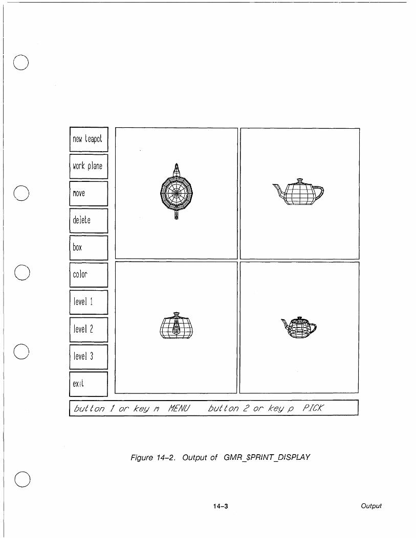
o
new teapot
work plane
0 EJ ~
~ ,[I ~ EJ T
D 0 EJ ~ EJ • .,
0 EJ EJ I but t 017 1 or key 17 )fE/Vii but t 017 ;:> or key p PICK
Figure 14-2. Output of GMR_$PRINT_DISPL4Y
o 14-3 Output

c
(=
c

o
c'
o
o
Appendix A
Sample Pascal Programs
The programs listed here are also listed in Appendices Band C in FORTRAN and C respectively. These programs are on-line under the names
....... / domain _ examples/ gmr3d/ sample 1. pas ........ /domain_examples/gmr3d/sample3.pas
Sample1.pas Sample1.pas is an example of the basic use of the 3D GMR package. The program performs the following operations:
1. Creates a structure named "sphere" that contains a polyline sphere.
2. Creates a second structure "spheres" and instances "sphere" three times: each time using a different transformation (scaling, translating, and rotating the sphere) and attribute class.
3. Assigns the structure "spheres" to the default viewport and draws it.
4. Inquires the configuration of the device and if the device is a color node, redraws "spheres" using different colors.
5. Exits the program when the user moves the cursor to the shell input pad and presses RETURN.
Sample3.pas Sample3.pas demonstrates picking, the use of multiple viewports, and the use of the work plane for 3D input. The program displays a teapot in four different views and creates several views that can be edited.
Sample3. pas creates viewports for the menu and prompt.· However, if your application uses menus, we recommend that you use DOMAINlDialogue to create the menus. Then you can run 3D GMR within DOMAINlDialogue. See the DOMAIN/Dialogue User's Guide for more information on DOMAINlDialogue.
A-1

A.1. Sample1.pas
This program creates an instance of a sphere and draws it.
{*****************************************************************************} PROGRAM SPHERE; { insert files }
%include '/sys/ins/base.ins.pas'; %include '/sys/ins/error.ins.pas'; %include '/sys/ins/pfm.ins.pas'; %include '/sys/ins/gmr3d.ins.pas';
{ constant variables }
CONST MAX_SPHERE_SECTION MAX_CIRCLE_SECTION PI = 3.1415926535;
{ global variables }
VAR
128; 128;
The number of z sections of the sphere }
The number of lines in a circle in a section
sph ARRAY [0 .. MAX_.SPHERE_SECTION - 1] OF ARRAY [0 .. MAX_CIRCLE_SECTION - 1]
{ The array for the sphere }
of gmr_$f3_vector_t; INTEGER;
cir_siz INTEGER; status status_$t; str ARRAY [1 .. 100] OF CHAR; bitmap_size: gmr_$i2_point_t:= [1024,1024]; plane cnt INTEGER:= 8; config gmr_$display_config_t; char_name_cnt: INTEGER; file id gmr_ $file id t· - - - , sphere_ id gmr_ $structure id t· - - , spheres_ id gmr_ $structure id t· - - , mat gmr_ $4x3 _matrix t· - , aclass1 gmr_ $aclass - id - t .- 3 ; aclass2 gmr_ $aclass id_ t .- 5' - , scale1 gmr_ $f3 _vector - t .- 0.5, 0.5, scale2 gmr_ $f3 - vector t .-- 0.2, 0.4, rotate1 gmr_ $f3 - vector - t .- 1.8, 2.7, rotate2 gmr_ $f3 _vector - t .- 5.4, 1.7, trans1 gmr_ $f3 _vector - t .- 0.3, 0.3, trans2 gmr_ $f3 vector t '- [-0.3, -0.2, - - .-vpid gmr_$viewport_ id t· - , ablock1 gmr_ $ablock_ id t· - , ablock2 ·gmr_ $ablock_ id t· - , color1 gmr_ $colar - id - t .- 1; color3 gmr_ $color - id - t .- 3 ;
A-2
{ The actual number of sections { The actual number of line/circle { status return variable
{ place keeper for ending { The bitmap size
{ Number of planes to use
{ Return con fig var for the node { Number of chars in a string name { The returned file ID { The returned structure ID
{ composite spheres ID
{ Matrix used for modelling { Special aclasses used in demo
0.5]; { Special scaling for demo}
0.6];{ Nonuniform scaling here}
4.4]; { Rotations about the axis
1.4] ; 0.3];{ Translation for demo
-0.5] ; { Viewport ID number
{ Ablock IDs used for demo
colors used
}
}
}
}
}
}
}
}
}
}
}
}
}
c~
---------------- ~~~~~- ----------------~--

(j
o
o
o
color4 color7 full inten numylanes size
%EJECT;
gmr_$color_id_t := 4; gmr_$color_id_t := 7; gmr_$intensity_t .- 1.0; gmr_$i_t; gmr_$i2_point_t;
{ Full intensity
{* * * * * * * * * * * * * * * * * * * * * * * * * * * * * * * * * * * * * * * }
PROCEDURE check;
function: checks the status and exits if an error occurs
BEGIN IF (status.all <> gmr_$operation_ok) THEN BEGIN
END; END;
writeln( ~status in module example: ~ status.all); pfm_$error_trap( status );
%EJECT; {* * * * * * * * * * * * * * * * * * * * * * * * * * * * * * * * * * * * * * * }
VAR
function: generates points for a sphere
parameters:
integer) ;
cir_sec - the number of points for determining a circle of latitude sph_sec - the number of circles for the sphere
i,j radians
integer; double;
radius,z : real;
Loop control variables }
Current radian angle for circle }
The circle radius and z component
BEGIN
{ For all sections do }
FOR i := 0 TO sph_sec-1 DO BEGIN
{ Compute z from -1 to 1 and determine the radius. }
z := -1.0 + 2.0*i/(sph_sec-1); radius := sqrt(1.0 - (z*z»;
{ For all line segments of the circle compute x and y. }
FOR j .- 0 TO cir_sec - 1 DO BEGIN
A-3

END;
radians := 2.0*PI*j/cir_sec; sph[i] [j].x .- radius*cos(radians); sph[i] [j].y .- radius*sin(radians); sph [i] [j] . z . - z;
END ;
END; {procedure}
%EJECT; {* * * * * * * * * * * * * * * * * * * * * * * * * * * * * * * * * * * * * * * } PROCEDURE make_sphere_instance (IN cir_sec, sph_sec : integer );
VAR
{
function: generates an instance of a polyline sphere
parameters: cir_sec - number of points per section sph_sec - number of sections of the sphere
pts ARRAY [0 .. 5] of gmr_$f3-point_t; i,j,m : integer;
BEGIN
array to send to GMR }
loop controls }
{ For all sections, connect adjacent two to form polylines. }
FOR i := 0 TO sph_sec - 2 DO BEGIN
FOR j := 0 TO cir_sec - 1 DO BEGIN
pts[O].x := sph[i] [j] .x; pts[O].y := sph[i] [j] .y; pts[O].z .- sph[i][j].z; pts[4].x .- sph[i] [j] .x; pts[4].y := sph[i] [j] .y; pts[4].z .- sph[i] [j].z; m .- j + 1; IF (m >= cir_sec) THEN
m .- 0; pts[1] .x .- sph[i] [m].x; pts[1].y .- sph [i] [m] . y; ptS[1].z .- sph[i] [m] .z; pts[2].x .- sph[i + 1] [m] . x; pts[2] .y .- sph[i + 1] [m] .y; pts[2] .z .- sph[i + 1][m].z; pts[3] .x .- sph[i + 1][j].x; pts[3] .y .- sph[i + 1][j].y; pts [3] . z . . - sph[i + 1] [j] . z; gmr_$f3_polyline( 5, pts, FALSE,
END; END;
END; {procedure
A-4
status ) ; check;
c
c
c.~
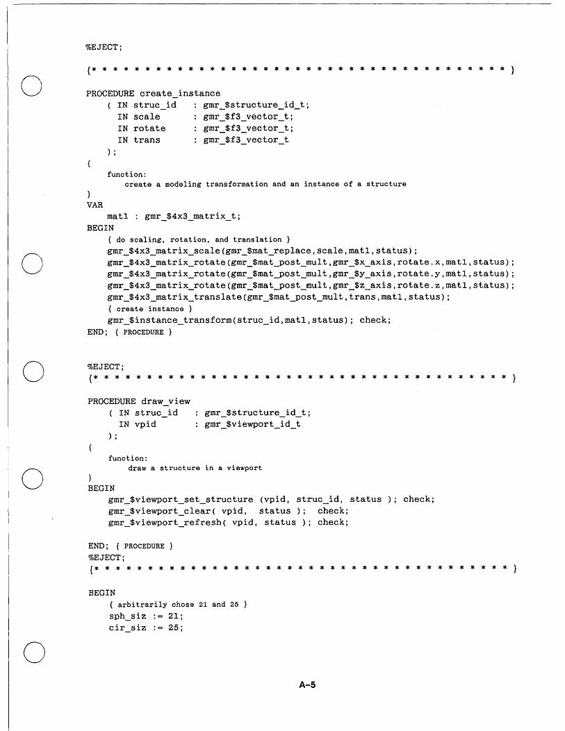
o
o
o
o
o
%EJECT;
{* * * * * * * * * * * * * * * * * * * * * * * * * * * * * * * * * * * * * * * }
PROCEDURE create_instance ( IN struc_id gmr_$structure_id_t;
IN scale gmr_$f3_vector_t; IN rotate gmr_$f3_vector_t; IN trans gmr_$f3_vector_t
) ;
function: create a modeling transformation and an instance of a structure
VAR mat1 : gmr_$4x3_matrix_t;
BEGIN { do scaling, rotation, and translation gmr_$4x3_matrix_scale(gmr_$mat_replace,scale,mat1,status); gmr_$4x3_matrix_rotate(gmr_$mat_post_mult,gmr_$x_axis,rotate.x,mat1,status); gmr_$4x3_matrix_rotate(gmr_$mat-post_mult,gmr_$y_axis,rotate.y,mat1,status); gmr_$4x3_matrix_rotate(gmr_$mat_post_mult,gmr_$z_axis,rotate.z,mat1,status); gmr_$4x3_matrix_translate(gmr_$mat_post_mult,trans,matl,status); { create instance } gmr_$instance_transform(struc_id,mat1,status); check;
END; {PROCEDURE}
%EJECT; {* * * * * * * * * * * * * * * * * * * * * * * * * * * * * * * * * * * * * * * }
PROCEDURE draw_view ( IN struc_id
IN vpid gmr_$structure_id_t; gmr_$viewport_id_t
) ;
function: draw a structure in a viewport
BEGIN gmr_$viewport_set_structure (vpid, struc_id, status ); check; gmr_$viewport_clear( vpid, status); check; gmr_$viewport_refresh( vpid, status ); check;
END; {PROCEDURE
%EJECT; {* * * * * * * * * * * * * * * * * * * * * * * * * * * * * * * * * * * * * * * }
BEGIN { arbitrarily chose 21 and 25 }
sph_siz .- 21; cir_siz .- 25;
A-5

{ Initialize the package and try to open the file. } gmr_Sinit ( gmr_Sdirect, stream_Sstdout, bitmap_size,
plane_cnt, status ); check;
char_name_cnt := 14; gmr_$file_open ( 'example_gmfile', char_name cnt, gmr_$wr, gmr_$lw,
file_id, status );
{ If couldn't open, create a new one. }
IF ( status.all <> gmr_Soperation_ok ) THEN BEGIN
gmr_Sfile_create ( 'example_gmfile', char_name_cnt, gmr_$overwrite, gmr_S1w, file_id, status ); check;
{ create a sphere structure.
char_name_cnt := 6; gmr_Sstructure_create ( 'sphere', char_name_cnt,
, status ); check; gen_sphere (cir_siz,sph_siz); make_sphere_instance(cir_siz,sph_siz); gmr_Sstructure_close (TRUE, status); check;
{ create a composite of spheres.
char_name_cnt := 7; gmr_Sstructure_create ( 'spheres', char_name_cnt, spheres_id
, status ); check; gmr_Sfile_set_primary_structure(spheres_id, status); check; { Make the first as is. }
gmr_S4x3_matrix_identity(mat,status); gmr_$instance_transform(sphere_id,mat,status); check; { make the next two with aclass bindings and modeling transformations
gmr_Sattribute_source(gmr_Sattr_line_color, gmr_Sattribute_aclass, status); check;
gmr_Saclass(aclass1,status); check; create_instance(sphere_id,scale1,rotatel,transl); gmr_Saclass(aclass2,status); check; create_instance(sphere_id,scale2,rotate2,trans2); gmr_Sstructure_close (TRUE, status); check;
END ELSE { Because the file existed, get the ID of the sphere structure. }
BEGIN
char_name cnt := 7; gmr_Sstructure_inq_id('spheres' ,char_name_cnt,spheres_id,status); check;
END;
{ Connect the structure to the default viewport and draw it. }
vpid := 1; draw_view(spheres_id,vpid);
A-6
c
c~
(" '----

o END.
o
o
o
gmr_$inq_config( gmr_$direct, stream_stdout, num_planes, size, status); { Add other colors if not b/w, and redraw. }
IF (num_planes > 1) THEN BEGIN gmr_$viewport_set_bg_color(vpid,color3,full_inten, statu s); check; gmr_$ablock_create(gmr_$default_ablock, ablock1 , status) ; check; gmr_$ablock_assign_viewport(aclass1,vpid,ablock1,status); check; gmr_$ablock_set_line_color(ablock1,color4,gmr_$set_value_and_enable,
status); check; gmr_$ablock_create(gmr_Sdefault_ablock,ablock2,status); check; gmr_$ablock_assign_viewport(aclass2,vpid,ablock2,status); check; gmr_$ablock_set_line_color(ablock2,color7, gmr_$set_value_and_enable,status); check; draw_view(spheres_id,vpid); END;
Wait here until carriage return. }
readln(str);
{ clean up and exit. } gmr_$file_close ( TRUE, status ); check; gmr_$terminate ( status ); check;
A-7

· A.2 Sample3.pas
This sample program demonstrates picking, the use of multiple viewports, and the use of C work planes for input in 3D. A teapot is displayed in four viewports, each with different ./ viewing parameters.
The user can set the picking level:
level 1 = entire teapot
level 2 = top or base
level 3 = knob, cover, pot, spout, or base
The user can set the highlighting method: bounding box (must be used for black and white) or color (highlights in a different color).
The user can set the work plane. The cursor position determines two coordinates and the work plane determines the third coordinate. Once a structure is picked, it can be deleted or moved. If the move menu item is chosen, the user is prompted to indicate the new location.
{**********************************************************************}
PROGRAM pick_demo;
%NOLIST; %INCLUDE '/sys/ins/base.ins.pas'; %INCLUDE '/sys/ins/time.ins.pas'; %INCLUDE '/sys/ins/error.ins.pas'; %INCLUDE '/sys/ins/pgm.ins.pas'; %INCLUDE '/sys/ins/gmr3d.ins.pas'; %INCLUDE'sample3_pts.ins.pas';
%LIST;
%EJECT;
CONST
{ This data file comes on-line with the the 3D GMR package. It is supplied specifically for this sample program.
menu_xmin 0.025; {Menu area in Logical Device Coordinates} menu_xmax 3.0.; menu_ymin 0.090; menu_ymax 0.990;
wind_xmin wind_xmax wind_ymin wind_ymax
0.0; 30.0; 0.0; 10.0;
num_buttons = 10; 4' I
{Window for each menu button}
A-8

o
o
o
o
o
VAR j
status bitmap_size num_of_planes
first_msg menu_item prev_menu_item
ablock1, ablock2, ablock3, ablock4
integer; status_$t; gmr_$i2_point_t .- [1024,1024]; gmr_$i_t;
boolean; integer; integer;
ARRAY [1 .. num_buttons] OF name_$pname_t := ['button1' 'button2' 'button3' 'button4 " 'button5' 'button6' 'button7 " 'buttonS' 'button9'
'button10'] ;
ARRAY [1 .. num_buttons] OF gmr_$string_t.- ['new teapot' , 'work plane' , 'move 'delete 'box
'color 'level 1 'level 2 'level 3 'exit ' ] ;
main_id, pot_id, handle_id, spout_id, knob_id, cover_id, base_id, top_id, teapot_id button_id message_id
gmr_$structure_id_t; ARRAY [1 .. num_buttons] OF gmr_$structure_id_t; gmr_$structure_id_t;
A-9
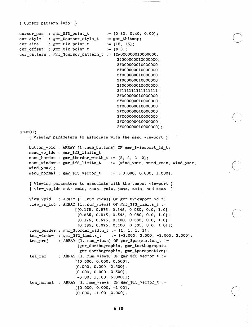
{ Cursor pattern info: }
cursorJ>os cur_style cur_size cur_offset curJ>attern
%EJECT;
.-
.-
.-
.-
[0.80, 0.40, 0.00] ; gmr_$bitmap; [15, 15] ; [8,8] ;
{ Viewing parameters to associate with the menu viewport }
button_vpid menu_vp_Idc menu_border menu_window wind_ymax] ; menu_normal
ARRAY [l .. num_buttons] OF gmr_$viewport_id_t; gmr_$f3_limits_t; gmr_$border_width_t .- [2, 2, 2, 2]; gmr_$f2_limits_t .- [wind_xmin, wind_xmax, wind_ymin,
0.000,0.000, 1.000];
{ Viewing parameters to associate with the teapot viewport} { view_vp_ldc sets xmin, xmax, ymix, ymax, zmin, and zmax }
view_vpid view_vp_ ldc
view_border tea_window teaJ>roj
tea_ref
tea normal
ARRAY [1 .. num_views] OF gmr_$viewport_ id t· - , ARRAY [1 .. num_views] OF gmr_ $f3 - limits - t .-
[[0.175, 0.575, 0.545, 0.980, 0.0, 1.0] , [0.585, 0.975, 0.545, 0.980, 0.0, 1.0] , [0.175, 0.575, 0.100, 0.535, 0.0, 1.0] , [0.585, 0.975, 0.100, 0.535, 0.0, 1.0] ] ;
gmr_$border_width_t := [1, 1, 1, 1]; gmr_$f2_limits_t := [-3.000, 3.000, -3.000, 3.000]; ARRAY [l .. num_views] OF gmr_$projection_t :=
[gmr_$orthographic, gmr_$orthographic, gmr_$orthographic, gmr_$perspective];
ARRAY [1 .. num_views] OF gmr_$f3_vector_t .[[0.000, 0.000, 0.500], [0.000, 0.000, 0.500], [0.000, 0.000, 0.500], [-5.00, 15.00, 5.000]];
ARRAY [1 .. num_views] OF gmr_$f3_vector_t .[[0.000, 0.000, -1.00], [0.000, -1.00, 0.000],
A-10
c~
C'"

o
o
o
o
o
tea hd
%EJECT;
[-1.00, 0.000, 0.000], [5.000, -15.0, -4.50]];
ARRAY [1 .. num_views] OF gmr_$f3_vector_t .[[1.000, 0.000, 0.000], [0.000, 0.000, 1.000], [0.000, 0.000, 1.000], [0.000, 0.000, 1.000]];
ARRAY [1 .. num_views] OF real .[-50.0, -50.0, -50.0, 1.0];
ARRAY [1 .. num_views] OF real [0.0, 0.0, 0.0, 12.0];
ARRAY [l .. num_views] OF real [50.0, 50.0, 50.0, 50.0];
{ Viewing parameters for message viewport }
message_vpid message_vp_ldc cur_msg
gmr_$viewport_id_t; gmr_$f3_limits_t .- [0.025, 0.975, 0.025, 0.075, 0.0, 1.0]; integer;
{ Colors for defining ranges }
gmr_$rgb_color_t .- [0.00, 0.50, 1.00]; gmr_$rgb_color_t .- [0.00, 0.25, 0.50];
{ Pick information }
cur_pick_path no_last_pick last_hl_vp level cur_level
gmr_$instance-path_t; boolean := TRUE; gmr_$viewport_id_t; gmr_$i_t := 3; gmr_$i_t;
{ Cumulative transformation matrix (cmt) for each instance }
base ctm top_ctm pot_ctm spout_ctm handle_ctm cover_ctm knob_ctm teapot_ctm
%EJECT;
gmr_$4x3_matrix_t; gmr_$4x3_matrix_t; gmr_$4x3_matrix_t; gmr_$4x3_matrix_t;
:-gmr_$4x3_matrix_t; gmr_$4x3_matrix_t; gmr_$4x3_matrix_t; gmr_$4x3_matrix_t;
A-11
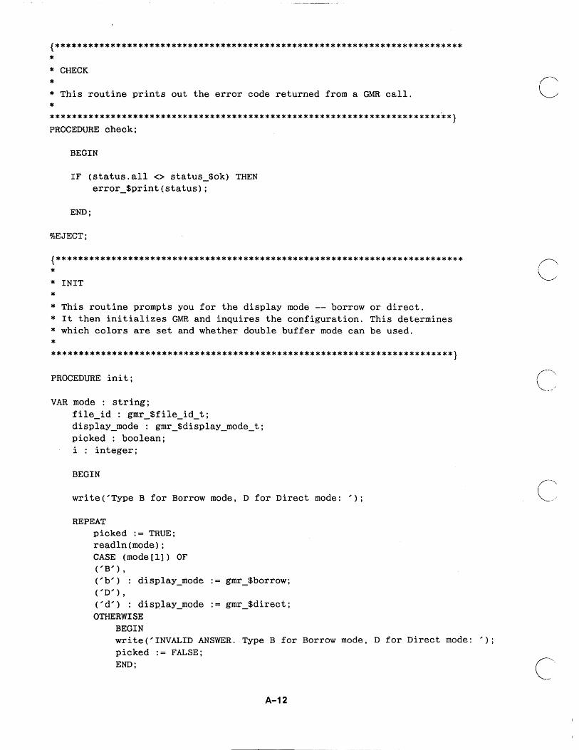
{************************************************************************** * * CHECK
* * This routine prints out the error code returned from a GMR call.
* *************************************************************************} PROCEDURE check;
BEGIN
IF (status.all <> status_$ok) THEN error_$print(status);
END;
%EJECT;
{************************************************************************** * * INIT
* * This routine prompts you for the display mode -- borrow or direct. * It then initializes GMR and inquires the configuration. This determines * which colors are set and whether double buffer mode can be used.
* *************************************************************************}
PROCEDURE init;
VAR mode : string; file_id : gmr_$file_id_t; display_mode : gmr_$display_mode_t; picked : boolean; i : integer;
BEGIN
write('Type B for Borrow mode, D for Direct mode: ');
REPEAT picked := TRUE; readln (mode) ; CASE (mode[l]) OF ('B'),
('b') : display_mode .- gmr_$borrow; ('D' ) ,
('d') : display_mode .- gmr_$direct; OTHERWISE
BEGIN write('INVALID ANSWER. Type B for Borrow mode, D for Direct mode: '); picked .- FALSE; END;
A-12
c

o
o
o
o
o
END;
UNTIL (picked writeln;
TRUE);
gmr_$init(display_mode, stream_$stdout, bitmap_size, 8, status); check; gmr_$file_create('gmfile.pick', 11, gmr_$overwrite, gmr_$lw, file_id,
status); check;
gmr_$inq_config(display_mode, stream_$stdout, num_of_planes, bitmap_size, status); check;
END;
%EJECT;
{************************************************************************** * * DISPLAY_VIEWPORT
* * * This routine displays the viewport with ID vpid.
* *************************************************************************} PROCEDURE display_viewport(IN vpid: gmr_$viewport_id_t);
BEGIN
gmr_$viewport_clear(vpid, status); check; gmr_$viewport_refresh(vpid, status); check;
END;
%EJECT; {*************************************************************************** * * INIT_MESSAGE
* * This routine initializes the menu structure and the viewing paramters for * the menu viewport Different messages are displayed by "scrolling" the * message window.
* *************************************************************************} PROCEDURE init_message;
VAR pos
A-13

BEGIN
pos.x .- 3.0; pos.z .- 0.0;
gmr_Sstructure_create('message', 7, message_id, status); check; gmr_Stext_color(7, status); check; gmr_Stext_height(4.0, status); check; gmr_Stext_slant(0.5, status); check;
pos.y := 3.0; gmr_Stext('button 1 or key m: MENU button 2 or key p: PICK', 50, pos,
status); check;
pos.y := 13.0; gmr_Stext('Pick new location in any view with button 2 or key p', 52, pos,
status); check; pOS.y .- 23.0; gmr_Stext('Pick point on work plane in any view with button 2 or key p', 59,
pos, status); pos.y .- 33.0; gmr_Stext('Must pick structure first.', 26, pos, status); check; gmr_sstructure_close (TRUE , status); check;
gmr_Sviewport_create(message_vp_ldc, message_vpid, status); check; gmr_Sviewport_set_border(message_vpid, menu_border, TRUE, 3, 1.0, status);
check; gmr_Sviewport_set_bg_color(message_vpid, 2, 1.0, status); check; gmr_Sview_set_view~lane_normal(message_vpid, menu_normal, status); check;
gmr_Sviewport_set_structure(message_vpid, message_id, status); check;
END;
%EJECT; {************************************************************************** * * DISPLAY_MESSAGE
* * This routine displays message message_no by setting the appropriate window.
* * *************************************************************************} PROCEDURE display_message(IN message_no: integer);
VAR
message_window
A-14
c
o
o
o
o
BEGIN
cur_msg := message_no; message_window.xmin .- 0.0; message_window.xmax .- 180.0; message_window.ymin .- (message_no - 1) * 10.0; message_window.ymax .- message_window.ymin + 10.0;
gmr_$view_set_window(message_vpid, message_window, status); check; display_viewport(message_vpid);
END;
%EJECT;
{***************************************************************************** * * CREATE_MENU_STRUCTURE
* * This routine creates a structure for each of the buttons in the menu. * Aclass1 is associated with the structure. Text for each button label is * inserted into the structure.
* *************************************************************************}
PROCEDURE create_menu_structure;
VAR pos i integer;
BEGIN pos.x .- 3.0; pos.y .- 4.0; pos.z .- 0.0;
FOR i .- 1 TO num_buttons DO
BEGIN
END;
gmr_$structure_create(button_struct_name[i], 8, button_id[i], status); check;
gmr_$attribute_source(gmr_attr_text_height, gmr_$attribute_aclass, status); check;
gmr_$attribute_source(gmr_attr_text_slant, gmr_$attribute_aclass, status); check;
gmr_$attribute_source(gmr_attr_text_color, gmr_$attribute_aclass, status); check;
gmr_$aclass(l, status); check; gmr_$text(button_text[i], 10, pos, status); check; gmr_$structure_close(TRUE, status); check; END;
A-15

%EJECT;
{**************************************************************************
* * INIT_MENU_VIEWPORT
* * This routine creates three ablocks. The first is for unhighlighted menu button * text, the second for italics (from setting the slant attribute), and the third * for highlighted menu text (slanted and a different color).
* * A viewport is created for each button, the button structure is displayed in the * viewport, and ablockl is assigned to aclassl for each viewport.
* *************************************************************************} PROCEDURE init_menu_viewport;
VAR real; integer;
BEGIN
menu _vp_ ldc.xmin .- menu _xmin; menu _vp_ ldc.xmax .- menu _xmax; menu_vp_Idc.ymin .- 0.90; menu_vp_ldc.ymax .- 0.98; menu _vp_ ldc.zmin .- 0.0; menu_vp_ ldc.zmax .- 1.0;
text_height := 3.0;
gmr_$ablock_create(gmr_$nochange_ablock, ablockl, status); check; gmr_$ablock_set_text_color(ablockl, 7, gmr_$set_value_and_enable, status);
check; gmr_$ablock_set_text_height(ablockl, text_height, gmr_$set_value_an~_enable,
status); check; gmr_$ablock_set_text_slant(ablockl, 0.0, gmr_$ set_value_and_enab Ie , status);
check; gmr_$ablock_set_text_expansion(ablockl, 0.8, gmr_$set_value_and_enable,
status); check;
gmr_$ablock_create(ablockl, ablock2, status); check; gmr_$ablock_set_text_slant(ablock2, 0.5, gmr_$set_value_and_enable,
status); check;
gmr_$ablock_create(ablock2, ablock3, status); check; gmr_$ablock_set_text_color(ablock3, 0, gmr_$set_value_and_enable, status);
check;
A-16
----------_. __ . __ . __ ._---- ....
c
c

o
o
o
o
FOR i .- 1 TO num_buttons DO BEGIN
END;
gmr_$viewport_create(menu_vp_ldc, button_vpid[i], status); check; gmr_$viewport_set_border(button_vpid[i], menu_border, TRUE, 3, 1.0,
status); check; gmr_$viewport_set_bg_color(button_vpid[i], 2, 1.0, status); check; gmr_$view_set_window(button_vpid[i], menu_window, status); check;
gmr_$view_set_view_plane_normal(button_vpid[i], menu_normal, status); check;
gmr_$viewport_set_structure(button_vpid[iJ, button_id[i], status); check; gmr_$ablock_assign_viewport(l, button_vpid[i], ablock1, status); check;
menu_vp_ldc.ymin .- menu_vp_ldc.ymin 0.09; menu_vp_ldc.ymax .- menu_vp_ldc.ymax - 0.09;
END;
%EJECT;
{************************************************************************** * * INIT_TEAPOT_CTM
* * This routine initializes the ctm (cumulative translation matrix) for each * structure. Each structure is centered around its origin and its translation * matrix positions it appropriately.
* *************************************************************************}
PROCEDURE init_teapot_ctm;
BEGIN
gmr_$4x3_matrix_identity(top_ctm, status); top_ctm[4] [3] := 0.9;
gmr_$4x3_matrix_identity(knob_ctm, status); knob_ctm[4] [3] := 0.12;
gmr_$4x3_matrix_identity(spout_ctm, status); spout_ctm[4] [1] := 0.68;
A-17

spout_ctm[4] [3] := 0.18;
gmr_S4x3_matrix_identity(handle_ctm, status); handle_ctm[4] [1] .- -0.76; handle_ctm[4] [3] := 0.18;
END;
%EJECT;
{**************************************************************** * * CREATE_TEAPOT_STRUCTURE
* * This routine creates the tree of structures to be displayed, * moved, and deleted. * The tree is the following:
* * main * * teapot * / \ * base top * / \ / \ * spout pot handle knob cover * * * Each structure is instanced by its parent structure using its ctm.
* *****************************************************************}
PROCEDURE create_teapot_structure;
VAR index, i integer;
BEGIN
gmr_Sstructure_create('pot', 3, pot_id, status); check; FOR i := 1 TO 96 DO
BEGIN index := 4 * (i - 1) + 1; gmr_Sf3-polyline(4, pot [index] , FALSE, status); check; END;
gmr_Sstructure_close(TRUE, status); check;
gmr_Sstructure_create('handle', 6, handle_id, status); check; FOR i := 1 TO 32 DO
BEGIN' index := 4 * (i - 1) + 1;
A-18
c
c

o
o
u
o
o
gmr_$f3-polyline(4, handle [index] , FALSE, status); check; END;
gmr_$structure_close(TRUE, status); check;
gmr_$structure_create('spout', 5, spout_id, status); check; FOR i := 1 TO 32 DO
BEGIN index := 4 * (i - 1) + 1; gmr_$f3-polyline(4, spout [index] , FALSE, status); check; END;
gmr_$structure_close(TRUE, status); check;
gmr_$structure_create('knob', 4, knob_id, status); check; FOR i := 1 TO 32 DO
BEGIN index := 4 * (i - 1) + 1; gmr_$f3-polyline(4, knob [index] , FALSE, status); check; END;
gmr_$structure_close(TRUE, status); check;
gmr_$structure_create('cover', 5, cover_id, status); check; FOR i := 1 TO 32 DO
BEGIN index := 4 * (i - 1) + 1; gmr_$f3-polyline(4, cover [index] , FALSE, status); check; END;
gmr_$structure_close (TRUE , status); check;
{* The base is made up of the pot, handle, and spout.
gmr_$structure_create('base', 4, base_id, status); check; gmr_$instance_transform(pot_id, pot_ctm, status); check; gmr_$instance_transform(handle_id, handle_ctm, status); check; gmr_$instance_transform(spout_id, spout_ctm, status); check; gmr_$structure_close (TRUE , status);
{* The top is made up of the cover and the knob.
gmr_$structure_create('top', 3, top_id, status); check; gmr_$instance_transform(cover_id, cover_ctm, status); check; gmr_$instance_transform (knob_id , knob_ctm, status); check; gmr_$structure_close (TRUE , status);
{* The teapot is made up of the base and the top.
gmr_$structure_create('teapot', 6, teapot_id, status); check; gmr_$instance_transform(base_id, base_ctm, status); check; gmr_$instance_transform(top_id, top_ctm, status); check; gmr_$structure_close (TRUE , status);
A-19
*}
*}
*}

{* Main structure which instances teapot -- used for moving
gmr_$structure_create('main', 4, main_id, status); check; gmr_$instance_transform(teapot_id, teapot_ctm, status); check; gmr_$structure_close (TRUE , status);
END;
%EJECT;
{**************************************************************************
*
* This routine sets the 'viewing parameters for the specified viewport.
* *************************************************************************}
PROCEDURE set_view-parms(IN view: integer);
BEGIN
*}
gmr_$view_set_window(view_vpid[view] , tea_window, status); check; gmr_$view_set_reference-point (view_vpid [view] , tea_ref [view] , status); check; gmr_$view_set_view-plane_normal (view_vpid [view] , tea_normal [view] , status);
check; gmr_$view_set_up_vector(view_vpid[view] , tea_up [view] , status); check; gmr_$view_set-projection_type (view_vpid [view] , tea_proj[view] , status);
check; gmr_$view_set_hither_distance(view_v~id[view], tea_hd[view] , status); check; gmr_$view_set_yon_distance (view_vpid [view] , tea_yd[view] , status); check; gmr_$view_set_view_distance (view_vpid [view] , tea_vd[view] , status); check;
END;
%EJECT;
{**************************************************************************
* * INIT_VIEWPORTS
* * This routine initializes each of the four viewports and the viewing parameters * for each viewport. It associates the main structure with each viewport and * sets the work plane to be parallel to the view plane passing through the * origin of the world coordinate system.
* *************************************************************************}
A-20
c
('

o
C)
o
o
PROCEDURE init_viewports;
VAR
i origin
BEGIN
integer; gmr_$f3J)oint_t;
origin.x := ,0.0; origin.y .- 0.0; origin.z := 0.0;
FOR i := 1 TO num_views DO BEGIN
gmr_$viewport_create(view_vp~ldc[iJ, view_vpid[iJ, status); check; gmr_$view_set_coord_system(view_vpid[iJ, gmr_$coord_left, status); check; gmr_$viewport_set_border(view_vpid[iJ, view_border, TRUE, 3, 1.0,
status); check; gmr_$viewport_set_bg_color(view_vpid[iJ, 2, 1.0, status); check;
set_viewJ)arms(i);
END;
END;
%EJECT;
{************************************************************************** * * SET_COLORS
* * This routine initializes the colors for both single- and' double-buffer modes. * ID 1 text * ID 2 viewport background * ID 3 viewport border * ID 4 menu highlight * ID 5 pick highlight
* *************************************************************************} PROCEDURE set_colors;
BEGIN
A-21
IF num_of-planes > 1 THEN
BEGIN { by default, color map location 7 is white, 3 is green} gmr_$color_set_range 1, 7, 1, status); check; gmr_$color_set_range 4, 7, 1, status); check; gmr_$color_set_range 5, 2, 1, status); check;
{ viewport background color } gmr_$color_set_range ( 2, 3, 1, status); check; gmr_$color_define_rgb( 2, dark_bg, dark_bg, status); check;.
{ viewport border color } gmr_$color_set_range ( 3, 4, 1, status); check; gmr_$color_define_rgb( 3, blue_g, blue_g, status); check;
END
ELSE { monochrome node }
END;
BEGIN gmr_$color_set_range (2, 0, 1, status); check; END;
%EJECT;
{**************************************************************************
* * SET_CURSOR_AND_INIT_INPUT
* * This routine enables input for the spacebar (through gmr_$keystroke), the * mouse, bitpad puck, or touchpad (through gmr_$locator) and the mouse or bitpad * puck button (through gmr_$buttons). The cursor is defined, set to an initial * position, and set active.
* *************************************************************************} PROCEDURE set_cursor_and_init_input;
BEGIN
gmr_$input_enable (gmr_$keystroke , [CHR(O) .. CHR(127)], status); check; gmr_$input_enable (gmr_$locator , [], status); check; gmr_$input_enable (gmr_$buttons , [CHR(O) .. CHR(127)], status); check;
gmr_$cursor_set_position(cursor-pos, status); check; gmr_$cursor_set-pattern(cur_style, cur_size, cur_pattern, cur_offset,
status); check; gmr_$cursor_set_active (TRUE , status); check;
END;
A-22

o
o
o
o
%EJECT;
{************************************************************************** * * INIT PICKING
* * This routine initializes the ablock to be used for highlghting. It sets the * line color and intensity. It also sets the pick path order, echo method, * highlight attribute block, and pick aperture.
* *************************************************************************} PROCEDURE init-picking; VAR
i := integer;
BEGIN
gmr_$ablock_create(gmr_$nochange_ablock, ablock4, status); check; gmr_$ablock_set_line_color(ablock4, 5, gmr_$set_value_and_enable,
status); check; gmr_$ablock_set_line_inten(ablock4, 1.0, gmr_$set_value_and_enable,
status); check; FOR i := 1 TO num_views DO
BEGIN
END;
gmr_$viewport_set-path_order(view_vpid[i], gmr_$top_first, status); check;
gmr_$instance_echo_set_method(view_vpid[i], gmr_$element_hl_bbox, status); check;
gmr_$viewport_set_hilight_ablock(view_vpid[i], ablock4, status); check;
gmr_$pick_set_aperture_size(viewpid[i], 0.01, 0.01, 2.0, status); check;
END;
%EJECT;
{************************************************************************** * * FIND_VIEWPORT
* * Given a point in ldc, this routine determines which viewport (if any) the * point is in.
* *************************************************************************} FUNCTION find_viewport(IN position: gmr_$f3-point_t; OUT vpid :
gmr_$viewport_id_t): boolean; VAR'
found boolean;
BEGIN
A-23
found := TRUE;
IF «position.x >= 0.175) AND (position.x <= 0.575» THEN BEGIN IF «position.y >= 0.545) AND (position.y <= 0.980» THEN
vpid := view_vpid[l] ELSE IF «position.y >= 0.100) AND (position.y <= 0.535» THEN
vpid := view_vpid[3] ELSE
found := FALSE; END
ELSE IF «position.x >= 0.585) AND (position.x <= 0.975» THEN BEGIN IF «position.y >= 0.545) AND (position.y <= 0.980» THEN
vpid := view_vpid[2] ELSE IF «position.y >= 0.100) AND (position.y <= 0.535» THEN
vpid := view_vpid[4] ELSE
found .- FALSE; END
ELSE found := FALSE;
find_viewport .- found;
END;
%EJECT;
{************************************************************************** * * PICK
* * This routine picks a structure (given a point). It highlights the structure * picked using the current highlighting method (bounding box or ablock).
* *************************************************************************}
PROCEDURE pick(IN position: gmr_$f3-point_t);
VAR pick_vpid pick_index pick data
BEGIN
pick_index := 1;
gmr_$viewport_id_t; integer32; gmr_$pick_data_t;
IF (find_viewport (position, pick_vpid) RETURN;
IF (no_last-pick = FALSE) THEN
A-24
FALSE) THEN
c·
~ ......... _ ••• '",,1
-------------._--

o
o
o
o
o
display_viewport(last_hl_vp); no_last-pick := TRUE;
gmr_Spick(pick_vpid, position, pick_index, gmr_Spick_data_size, pick_data, status);
IF «status.all <> gsr_Sno_further-picks) AND (status.all <> gmr_Soperation_invalid» THEN BEGIN
END;
check; gmr_Sins.tance_echo(pick_vpid, level, pick_data.pick-path, status); check; no_last-pick := FALSE; last_hl_vp := pick_vpid; cur-pick-path := pick_data.pick-path; cur_level .- level; END;
%EJECT;
{************************************************************************** * * GET_POSITION
* * This routine waits for the user to pick a position in one of the viewports * using either the second mouse button or the key p. It returns the position * picked in world coordinates.
* *************************************************************************} PROCEDURE get-position(OUT new-pos : gmr_Sf3-point_t);
VAR
position event vpid ch picked
BEGIN
picked .- FALSE;
REPEAT
gmr_Sf3-point_t; gmr_Sevent_t; gmr_Sviewport_id_t; char; boolean;
gmr_Sinput_event_wait (TRUE , event, ch, position, status); IF (status.all <> gmr_Slocator_outside_dev_limits) THEN
check; IF event = gmr_Slocator THEN
BEGIN WHILE (event = gmr_$locator) DO
BEGIN
A-25

END;
gmr_Sinput_event_wait(FALSE, event, ch, position, status); IF (status. all <> gmr_Slocator_outside_dev_limits) THEN check; END;
gmr_Scursor_set-position(position, status); check; END;
IF «(event = gmr_Sbuttons) AND (ch = 'b'» OR «event = gmr_Skeystroke) AND (ch = 'p'») THEN BEGIN IF (find_viewport (position, vpid» THEN
BEGIN gmr_Scoord_ldc_to_work_plane(vpid, position, new_pos, status);
check;
END;
picked .- TRUE; END;
UNTIL (picked TRUE) ;
%EJECT;
{************************************************************************** *
* This routine deletes all of the exisitng structures and calls * create_teapot_structure to create a new teapot. It calls init_teapot ctm to * initialize each ctm (i.e. no structures are moved). The new teapot is * displayed in each viewport.
* *************************************************************************}
PROCEDURE new_teapot;
VAR i : integer;
BEGIN
gmr_Sstructure_open(main_id, FALSE, status); check; gmr_Sstructure_delete(status); check;
gmr_Sstructure_open(teapot_id, FALSE, status); check; gmr_Sstructure_delete(status); check;
gmr_Sstructure_open(base_id, FALSE, status); check; gmr_Sstructure_delete(status); check; gmr_Sstructure_open(top_id, FALSE, status); check; gmr_Sstructure_delete(status); check;
A-26

o
o
o
o
o
gmr_$structure_open(cover_id, FALSE, status); check; gmr_$structure_delete(status); check; gmr_$structure_open (knob_id , FALSE, status); check; gmr_$structure_delete(status); check;
gmr_$structure_open(spout_id, FALSE, status); check; gmr_$structure_delete(status); check; gmr_$structure_open(handle_id, FALSE, status); check; gmr_$structure_delete(status); check; gmr_$structure_open(pot_id, FALSE, status); check; gmr_$structure_delete(status); check;
init_teapot_ctm; create_teapot_structure; FOR i := 1 TO num_views DO
display_viewport(view_vpid[i]); no_last_pick .- TRUE;
END;
%EJECT;
{***************************************************************************
* * MOVE
* * This routine moves the picked structure to a new position by instancing it * with a new transformation matrix. This new matrix is the product of two * matrices. The first is the translation matrix computed from the position * picked. The second is the inverse of the product of the matrices used to * instance the structure's parent structures. All four viewports are displayed * with the structure moved to its new position.
* * *****************************************************************************} PROCEDURE move(IN new_pos : gmr_$f3_point_t); VAR
i m m_inv trans_mat trans_mat_p mat_i BEGIN
integer; gmr_$4x3_matrix_t; gmr_$4x3_matrix_t; gmr_$4x3_matrix_t; gmr_$4x3_matrix_t;
" gmr_$4x3_matrix_t;
{ Compute product of all matrices used to instance its parent structures -- m }
FOR i := 1 TO level - 1 DO BEGIN gmr_$structure_open(cur_pick-path[i].structure_id, FALSE, status); check;
A-27

gmr_$element_set_index(cur-pick_path[i] . element_index, status); check; gmr_$inq_instance_transform(cur-pick-path[i] .structure_id, mat_i,
status); check; gmr_$4x3_matrix_concatenate(mat_i, m, m, status); gmr_$structure_close (FALSE , status); check; END;
{ Compute inverse of m -- m_inv }
{ Compute translation matrix from new position -- trans_mat }
{ Instance structure picked with new matrix -- trans_mat * m_inv }
gmr_$structure_open(cur_pick_path[level] .structure_id, FALSE, status); check; gmr_$element_set_index(cur-pick-path[level] . element_index, status); check;
gmr_$replace_set_flag (TRUE , status); check;. gmr_$instance_transform(cur_pick-path[level+l].structure_id, trans_mat_p,
status); check; gmr_$replace_set_flag(FALSE, status); check;
c
gmr_$structure_close (TRUE , status); check; ('
{ Display all four viewports. }
FOR i := 1 TO num_views DO display_viewport(view_vpid[i]); no_last-pick .- TRUE;
END;
%EJECT; {************************************************************************** * * DELETE
* * Delete erases all of the elements in the structure to be deleted.
* *************************************************************************}
PROCEDURE delete;
VAR i : integer;
BEGIN
A-28
\ ''-...

o
o
o
o
o
gmr_$structure_open(cur_pick-path[cur_level + 1] .structure_id, FALSE, status); check;
gmr_$structure_erase(status); check; gmr_$structure_close(TRUE, status); check;
FOR i := 1 TO num_views DO display_viewport(view_vpid[i]);
END;
%EJECT;
{************************************************************************** *
* This routine cases on the button picked and performs the appropriate actions. * If the viewport is to be refreshed, set the display_flag to true. If * you pick exit, set the end_flag to true.
* *************************************************************************}
PROCEDURE do_button(IN menu_item: integer; OUT end_flag: boolean);
VAR i clock new_pos
integer; time_$clock_t; gmr_$f3_point_t;
BEGIN
clock. low := 125000; clock. high := 0;
end_flag := FALSE;
CASE menu_item OF
1: {* Display a new teapot. *} new_teapot;
2: {* Change the work plane. *} BEGIN display_message(3); get-position(new-pos); FOR i := 1 TO num_views DO
gmr_$coord_set_work_plane (view_vpid [i] , new_pos, tea_normal[i], status); check;
END;
A-29

3: {* Move the structure/element to new location. *} IF (no_last-pick) THEN
display_message (4) ELSE
BEGIN display_message(2); get-position(new-pos); move (new-pos) ; END;
4: {* Delete an element/structure. *} IF (no_last_pick) THEN
display_message (4) ELSE
delete;
5: {* Highlight with a box. *} BEGIN. FOR i := 1 TO num_views DO
BEGIN gmr_Sinstance_echo_set_method(view_vpid[i], gmr_Selement_hl_bbox,
status); check; END;
time_Swait(TIME_SRELATIVE, clock, status); check; END;
6: {* Highlight with a ·different color. *} BEGIN FOR i := 1 TO num_views DO
BEGIN gmr_Sinstance_echo_set_method(view_vpid[i] ,
gmr_Selement_hl_ablock,status); check; gmr_Sviewport_set_highlight_ablock(view_vpid[i], ablock4,
status); check; END;
time_Swait(TIME_SRELATIVE, clock, status); check; END;
7: {* Allow picking at level 1, that is, entire teapot. *} BEGIN level := 1; time_Swait(TIME_SRELATIVE, clock, status); check; END;
.8: {* Allow picking at level 2, that is, base or top. *} BEGIN level := 2; time_Swait(TIME_SRELATIVE, clock, status); check; END;
9: {* 'Allow picking at level 3, that is pot, spout, handle or cover, knob. *}
BEGIN
A-30
-----------_._-----_._-._. __ ..
c

o
o
o
o
o
END;
level := 3; time_Swait(TIME_SRELATIVE, clock, status); check; END;
10: {* exit *} end_flag .- TRUE;
END; {case}
%EJECT;
{************************************************************************** * * CALC_MENU_ITEM
* * This routine determines if a menu button is picked and if so, which button. * It checks the cursor position against the bounds of the menu to accept or * reject. If the cursor is in the menu, it determines which button by its * relative position.
* *************************************************************************}
BEGIN
IF (position.x >= menu_xmin) AND (position.x <= menu_xmax) AND (position.y >= menu_ymin) AND (position.y < menu_ymax) THEN
menu_item .- num_buttons - TRUNC «(position.y - menu_ymin + 0.01) / (menu_ymax - menu_ymin» * num_buttons);
END;
%EJECT;
A-31

{************************************************************************** *
* This routine does the following: When the locator stops moving, it calls * calc_menu_item to determine if it is on a button. If so, it highlights that * button (and unhighlights the previous button picked). This is done by changing * the background color of the viewport and assigning a different ablock to the * viewport (i.e. change to italics to highlight). If a mouse button or the space * bar is pushed and the cursor is on the menu, the action processes the * associated command. After the command is processed, the viewport is refreshed * if the display flag is set to true.
* ************************************************************************} PROCEDURE process_commands;
VAR end_flag position event
boolean; gmr_$f3J)oint_t; gmr_$event_t; char; ch
BEGIN
menu_item := 0;
display_message(l);
REPEAT
gmr_$input_event_wait(TRUE, event, ch, position, status); IF (status.all <> gmr_$locator_outside_dev_limits) THEN check;
IF event = gmr_$locator THEN BEGIN
WHILE (event = gmr_$locator) DO BEGIN
{flush the queue}
gmr_$input_event_wait(FALSE, event, ch, position, status); IF (status.all <> gmr_$locator_outside_dev_limits) THEN
check; END;
gmr_$cursor_setJ)osition(position, status); check; prev_menu_item := menu_item; calc_menu_item(position, menu_item);
IF (menu~item <> prev_menu_item) THEN BEGIN IF (prev_menu_item <> 0) THEN
BEGIN gmr_$ablock_assign_viewport(l, button_vpid[prev_menu_item],
ablockl, status); check;
A-32

o
o
o
o
display_viewport(button_vpid[prev_menu_item]); END;
IF (menu_item <> 0) THEN BEGIN
END;
IF (cur_msg <> 1) THEN display_message(l);
END;
gmr_$ablock_assign_viewport(l, button_vpid[menu_item] , ablock2, status); check;
display_viewport(button_vpid[menu_item]); E~;
IF «(event = gmr_$buttons) AND (ch = 'a'» OR «event = gmr_$keystroke) AND (ch = 'm'») THEN
IF (menu_item <> 0) THEN BEGIN gmr_$viewport_set_bg_color(button_vpid[menu_item] , 4, 1.0,
status); check; gmr_$ablock_assign_viewport(l, button_vpid[menu_item] ,
ablock3, status); check; display_viewport(button_vpid[menu_item]); do_button (menu_item, end_flag); gmr_$viewport_set_bg_color(button_vpid[menu_item] , 2, 1.0,
status); check; gmr_$ablock_assign_viewport(l, button_vpid[menu_item] ,
ablock1, status); check; display_viewport(button_vpid[menu_item]); E~;
IF «(event «event BEGIN
gmr_$buttons) AND (ch = 'b'» OR gmr_$keystroke) AND (ch = 'p'») THEN
IF (cur_msg <> 1) THEN display_message(l);
position.z := 0.0; pick(position); END;
UNTIL end_flag = TRUE;
{* flusk the queue *} gmr_$input_event_wait(TRUE, event, ch, position, status); WHILE (event = gmr_$buttons) DO
gmr_$input_event_wait(FALSE, event, ch, position, status); END;
%EJECT;
A-33

{************************************************************************* * * CLOSE
* * Closes the metafile 'gmfile.pick' and terminates gmr.
* *************************************************************************}
PROCEDURE close;
BEGIN
gmr_$file_close (FALSE , status); check; gmr_$terminate(status); check;
END;
%EJECT;
{**************************************************************************
* * MAINLINE
* *************************************************************************}
BEGIN
init;
set_colors; set_cursor_and_init_input;
init_message;
create menu structure; init_menu_viewport; FOR j := 1 TO num_buttons DO
display_viewport(button_vpid[j]);
init_teapot_ctm; create_teapot_structure; init_viewports;
FOR j := 1 TO num_views DO display_viewport(view_vpid[j]);
initJ)icking;
process_com~ands;
close;
END.
A-34
c
C'

o Glossary
Attribute
Attribute block
o Attribute class
Attribute element
o Bit plane
Bitmap
o Borrow mode
Bounding box
o
A characteristic of the manner in which a primitive graphic operation is rendered (for example, line color or text height).
A data structure that holds a collection of attribute values.
A means for referring to a collection of attribute values from within a metafile. The particular attribute values are defined in an attribute block. Attribute classes allow you to assign attributes when rendering structures instead of when building them.
An element in a metafile that specifies how subsequent components of the picture are to be drawn and in what colors and intensities they are to be displayed.
A one-bit-deep layer of a bitmap. On a monochrome display, displayed bitmaps contain one bit plane. On a color display, displayed bitmaps may contain more bit planes depending on the hardware configuration and the number of bits per pixel.
A three-dimensional array of bits having width, height, and depth. When a bitmap is displayed, it is treated as a two-dimensional array of strings of bits, called pixel values. The color of each displayed pixel is determined by using the set of bits in the corresponding pixel of the frame-buffer bitmap as an index into the color table.
One of four 3D GMR display modes. The program borrows the entire screen from the Display Manager.
A rectangular parallepiped that encloses a structure and all structures that it instances. The 3D GMR package automatically maintains a bounding box around each structure. The bounding box is used to test for clipping, culling, and echoing.
Glossary-1

Button
Color map
Color map entry
Color map index
Color value
Coordinate systems
Culling
Current element
Current file
Current structure
Device coordinates
A logical input device used to provide a choice from a small set of alternatives. An example of a physical device of this type is the selection buttons on a mouse.
A table of color values typically indexed by a pixel value. Each color value contains red, green, and blue component values. Each entry is accessed by a color table index.
One location in a color map. Each entry stores one color value that can be accessed by a corresponding color map index.
An index to a particular entry in a color map.
The numeric encoding of a color. A color value is stored·· in a color map entry. Each color value consists of three component values: the first stores the value of the red component of the color, the second stores the value of the green component of the color, and the third stores the value of the blue component. Each component value is specified as a real number in the range 0.0 to 1.0, where 0.0 is the absence of the primary color and 1.0 is the full intensity color.
The five coordinate systems of 3D GMR: modeling coordinates, world coordinates, viewing coordinates, logical device coordinates, and device coordinates. See individual entries.
Limits the display of structures to those that are larger than a given screen-space area. This is a way of removing structures from the display that have become too small to be useful (or too small to be seen clearly).
The element in the current structure currently that you can inquire about, replace, or delete. When you open a structure, the first element becomes the current element.
The current element is identified by the element index.
The file in which operations are in progress. The current file can be changed by selecting another previously opened file or by opening (creating) an additional file.
The structure currently open for editing.
Used by the particular display device to map the image to the DM window or screen. The 3D GMR package maps the modeling coordinates that describe primitive positions and shapes to device coordinates when it renders the metafile.
Glossary-2
c
c
r '-.-.
c

o
o
o
o
o
Direct mode
Display
Display Manager
Display Manager window
Display mode
Echo
Element
Element index
File
One of four 3D GMR display modes. The program performs graphics operations i.n a window borrowed from the Display Manager. Direct mode allows graphics programs to coexist with other activities on the screen.
noun - The entire monitor screen. verb - To render. Displaying a structure implicitly includes displaying any instances of other structures found in that structure.
The program that manages the display and allocates Display Manager windows.
One section of the display, provided by the Display Manager. This window does not include the edges reserved by the Display Manager.
One of four modes for use of the 3D GMR package, selected when the 3D GMR package is initialized. See Borrow mode, Direct mode, Main-bitmap mode, and No-bitmap mode.
A method of visually differentiating elements or structures of interest from all others. You can acheive this visual signal in two ways:
1. Redrawing the element or subtree with a different color or linestyle. For this pupose 3D GMR provides a highlighting attribute block that can override attributes set by individual attribute elements or other attribute blocks.
2. Drawing a bounding box around the structure or subtree containing the element of interest.
An echo lasts only until the next viewport clear/refresh operation. An echo may result in an incorrect picture because the echoed object is redrawn over existing geometry.
A single, indivisible component of a structure. Elements are categorized as primitive elements, attribute elements, instance elements, and tag elements.
An indicator used to keep track of the elements in a structure. An element index is like a line number in a text file. It positions you within a structure so that you can insert, delete, replace, or copy elements.
See Metafile.
Glossary-3

Font
GM bitmap
Handedness
Hither distance in world coordinates
Input device
Input event
Instance element
Instance path
Instanced structure
One set of alphanumeric and special characters. A font is data that graphically describes a set of related character images.
The bitmap in which the 3D GMR package is initialized. In direct mode, this is part of the Display Manager window in which the package was initialized. In borrow mode, this is the entire current display. In main-bitmap mode, this is a main-memory bitmap.
The orientation of a coordinate system. In the viewing coordinate system, handedness controls how the U axis is related to the V and the N axes and how hither and yon clipping planes are defined. Two of three axes always determine the third in a right- or left-handed orthogonal system.
Used to specify part of the view volume. The N coordinate of the hither (or near) clipping plane. If the viewing coordinate system is left-handed, then points with N less than the hither distance are invisible. If the viewing coordinate system is right-handed, points with N greater than the hither distance are invisible.
A device such as a function key, touchpad, or mouse that enables an operator to provide interactive input to a program.
The result of a user's interaction with a device such as a keyboard, button, mouse, or touchpad. An event occurs when input is generated in a window (direct mode) or in the borrowed display (borrow mode).
An element in a metafile that calls for another structure to be displayed, with a particular transformation applied. This is similar to a subroutine call. Instancing allows multiple uses of a single sequence of elements.
The pathname of an instance of an element. This consists of a list of ordered pairs (structure ID, element index) that uniquely identify an element.
Given a hierarchy of structures, a given element can be instanced many times. An instance path distinguishes between those multiple elements. An instance path can either be returned from a pick operation or can be supplied directly by an application.
The structure referred to by an instance element in another structure.
Glossary-4
C~
c
(

o
o
o
o
Instancing structure
Intensity
Keyboard
Locator
Logical device coordina tes
Logical input device
Main-bitmap mode
Mesh element
Metafile
Modeling coordinates
Modeling routines
Multiline element
No-bitmap mode
The structure that contains the instance element that refers to the instanced structure.
The intensity or brightness used for the display of a particular element. A real number between 0 and 1 where 0.0 is the least intense and 1.0 is the most intense.
A logical input device used to provide character or text string input (e.g., the alphanumeric keyboard).
A logical input device used to specify positions in coordinate space (e.g., a touchpad, data tablet, or mouse).
Used to define the viewport in which an image is displayed. These are device independent, allowing the same metafile to be displayed on different types of DOMAIN nodes.
An abstraction that refers to any of a group of physical input devices that provide similar input data. For example, the logical input device "button" can refer to physical buttons on a mouse, or to physical buttons on a data tablet puck.
One of four 3D G:MR display modes. The program runs in a bitmap allocated in main memory, without using the display. This mode allows bitmaps larger than the full display.
A three-dimensional primitive element that draws a mesh.
A device-independent collection of picture data that can be displayed and edited (also referred to as a file).
Used to specify geometric properties of primitive elements in a structure. Each structure has its own modeling coordinate system. Modeling coordinates are also used to rotate, translate, and scale instanced structures.
Graphics metafile routines used to insert elements into metafiles or to edit metafiles.
A primitive element that, given N positions, draws N/2 disconnected line segments (see also polyline).
One of four 3D GMR display modes. The program runs without a main-memory or display bitmap. Viewing routines may not be performed in this mode. This mode provides the most efficient way to create a metafile from a data base. In this mode one cannot monitor a graphics display of the metafile during construction.
Glossary-5

Open file
Parallel projection
Perspective projection
Any of the files that have been opened during a session and have not yet been closed. More than one file may be open at one time.
Represents the metric properties of an object (for example, distances and angles) at the expense of realism. For example, receding parallel lines remain parallel giving a somewhat distorted appearance to the drawing for the casual viewer. Parallel projection is well suited for working drawings. There are three types of parallel projection in 3D GMR: orthographic, plan oblique, and elevation oblique.
Orthographic projection is typically used to show the exact shape of any side perpendicular to the view plane normal. It is well suited for rectangular objects. The user typically creates several orthographic views in order to see the object from several angles at once (for example, top, front, and right).
A plan oblique projection is typically used to show the exact shape of one side of an object and uses a foreshortening ratio to shorten lines that are perpendicular to that one side. These shortened lines are always drawn vertically in a plan oblique projection. The side for which· the shape is preserved is drawn at an angle (the receding angle) to these vertical lines. In 3D GMR, lines receding from the viewer (Le., lines perpendicular to the view plane and extending in the gaze direction), are drawn vertically downwards on the screen. The foreshortening ratio of a line is its projected length divided by its true length.
Elevation oblique is similar to plan oblique in that it also preserves the shape of one face of the object. Unlike plan oblique, that face is always shown upright. Lines receding from the viewer (i.e., lines in the gaze direction), are foreshortened and drawn at a given angle to the horizontal. However, receding parallel lines give the illusion of divergence to the inexperienced viewer.
Elevation oblique is well suited for objects with detail on mainly one face (for example, a radio). It is also widely used for building elevations.
Gives a realistic representation of an object as seen from an observer at a specific position. An object appears smaller the greater its distance from the observer. Parallel lines converge at a vanishing point (for example, railroad tracks give the appearance of converging in the distance).
Glossary-6
c
C~
C~I

o Pick aperture
Pick list
Pick operation
o Picture
Pixel
Pixel value
C) Polygon element
Polyline element
Polymarker element
o Primary structure
Primitive element
Reference point
o
Perspective projections are often used for presentation purposes and in advertising. They do not usually make good working drawings because it is difficult to judge metric properties such as distances, sizes, and angles.
The region in logical device coordinate space within which pick routines search for structures and elements.
An instance path that names an instance of a primitive draw elements in the metafile that meets a pick criterion.
The process of selecting an instance of a primitive draw element from among the primitive draw elements in a viewport. You use the GMR_$PICK routine to select a single element from a file and to retrieve the path through the hierarchy of structures to that element.
The entire contents of a file as drawn; it may be larger or smaller than either the viewport or the bitmap in which the 3D GMR package is running.
A single element of a two-dimensional displayed image or of a two-dimensional location within a bitmap.
The set of bits at a two-dimensional location within a bitmap. A pixel value is used as an index to the color map.
A primitive element that draws a polygon.
A primitive element that, given N positions, draws N-llinked line segments (see also multiline).
A primitive element that draws a set of markers. A marker is used to graphically identify a location in modeling coordinate space.
The structure explicitly assigned to be the logical start of the file for display purposes. This structure (or any other structure in the metafile) can be assigned to a viewport for display along with all of the structures that it instances.
An element in a structure that describes a single least divisible graphic operation of a stored picture. There are six types of primitive elements: polylines, multilines, polygons, polymarkers, mesh, and text.
The point that is the origin of the viewing coordinate system specified in world coordinates. All scalar viewing parameters are relative to the reference point. Additionally, for
Glossary-7

Render
Routine
Scan line
Structure
Structure mask
Structure value
Tag element
Temporary structure
Vertical (up) direction
Viewport
View distance in world coordinates
perspective projections, the reference point is the center of C projection. .
To produce a visual representation from a non-visual representation.
A procedure or function that operates on metafiles. The 3D GMR package is a collection of routines that can edit elements within metafiles and routines that can affect how elements are displayed.
A row of pixels; one horizontal line of a bitmap.
A collection of elements in a metafile that can be referred to as a group. See also current structure.
A number that you assign to a structure to determine if the structure will be visible and/or pickable in a given vewiport.
A value that you assign to a structure to specify whether it will be visible and/or pickable in a given viewport.
An element in a metafile that contains a comment. The comment data can be retrieved by the user, but is ignored when the file is displayed.
A structure that may be deleted when the file is closed. Useful for picture data that you want to display but not store (e.g., an enclosing box or superimposed grid). A temporary structure is not deleted at file close if it is instanced by a permanent structure.
Implicitly orients the window on the view plane in terms of the up vector. The up vector is key in determining the V axis of the viewing coordinate system. This setting, with the view plane normal, also implicitly sets the right vector because two of three vectors determine the third in a right- or left-handed orthogonal coordinate system.
All or part of the window, excluding its border if one exists. The viewport is the physical area in the window through which graphic· output or other processes are visible. Moving the viewport within the bitmap in which the 3D GMR package is running does not scale the view.
The signed distance between the reference point and the view plane, along the direction of gaze. In other words, it is the N coordinate of the view plane.
Glossary-8

o
View plane
o View plane normal
View volume
o View window
0
Viewing coordinates
Visibility
o
For an orthographic projection, the results are independent of view distance since the projection is parallel to the N axis.
For perspective projections, the view distance alters the divergence of the projection rays between the center of projection (reference point) and the window bounds of the view plane. For perspective projections, view distance must be negative if the viewing coordinate system is right-handed and positive if the viewing coordinate system is left-handed.
For plan oblique and elevation oblique projections, changing the view distance slides the projection across the view plane.
The plane in the viewing coordinate system defined by N = view plane distance. This is the plane in which the view window is specified.
The direction of the N axis of the viewing coorinate system. It establishes the orientation in space of the view plane centered on the origin of the view plane. The view plane normal vector can have any length but the vector cannot be identically zero.
The set of points in world coordinates between the hither and yon planes whose projections on the view plane lie within the view window. For parallel projections, the view volume is a parallelepiped with a rectangular cross-section. For perspective projections, the view volume is a frustum; that is, a truncated pyramid.
A rectangular region of the view plane that determines what portion of a projected image is displayed. Points in the region have coordinates satisfying:
umin < U< umax - -
vmin < v< vmax -
N = view distance
A three-dimensional coordinate system with axes labeled U, V, and N. Except for plan oblique projection, the U axis always corresponds to "right" on the screen and the V axis always corresponds to "up" on the screen. The N axis points into or out of the screen, depending on the handedness of the viewing coordinate system. In a right-handed coordinate system (default) N points out of the screen. In a left-handed system N points into the screen.
Determines whether or not a structure will be visible when it is displayed. Three techniques determine visibility: visibility
Glossary-9

Visibility mask
Visibility range
World coordinates
Yon distance in world coordinates
mask, visibility range, and name sets. A structure is C displayed only if it meets the visible range, visible mask, and / name set criteria.
A means of determining whether a structure is visible at display time. The structure mask is compared to the viewport's visibility mask. For the structure to be displayed, at least one bit must be "1" in both the structure mask and the viewport's visibility mask.
A range of visible values that is assigned to a viewport. A structure can be displayed only if the structure value lies between the specified bounds of the range, including the end values.
The name given to the modeling coordinate system of a structure displayed in a viewport. The world coordinate system is a right-handed, three-dimensional Cartesian coordinate system.
Used to specify part of the view volume. This value determines the signed distance of the yon (or far) clipping plane from the reference point. If the viewing coordinate system is left-handed, then points with N greater than the yon distance are invisible. If the viewing coordinate system is right-handed, points with N less than the yon distance are invisible.
Glossary-10
--_._ .. _-~---.----------------------

o
o
o
o
o
Index
The letter f means '~and the following page"; the letters If mean "and the following pages". Symbols are listed at the beginning of the index.
2D GMR compared to 3D GMR 13-7 (see DOMAiN 2D Graphics Metafile Resource)
3D GMR routines G:NIR_$4X3_MATRIX_CONCATENATE 5-4 GMR_$4X3_MATRIX_IDENTITY 5-4 GMR_$4X3_MATRIX_INVERT 5-4 GMR_$4X3_MATRIX_REFLECT 5-4 GMR_$4X3_MATRIX_ROTATE 5-4 GMR_$4X3_MATRIX_ROTATE_AXIS 5-4· GMR_$4X3_MATRIX_SCALE 5-4 GMR_$4X3_MATRIX_TRANSLATE 5-4 GMR_$ABLOCK_ASSIGN_DISPLAY 6-4, 9-13 GMR_$ABLOCK_ASSIGN_ VIEWPORT 6-4, 9-13 GMR_$ABLOCK_COPY 6-8 GMR_$ABLOCK_CREATE 6-5 GMR_$ABLOCK_DELETE 6-8 GMR_$ABLOCK_INQ_FILL_COLOR 6-7 GMR_$ABLOCK_INQ_FILL_INTEN 6-7 GMR_$ABLOCK_INQ_LINE_COLOR 6-7 GMR_$ABLOCK_INQ_LINE_INTEN 6-7 GMR_$ABLOCK_INQ_LINE_TYPE 6-7 GMR_$ABLOCK_INQ_MARK_COLOR 6-7 GMR_$ABLOCK_INQ_MARK_INTEN 6-7 GMR_$ABLOCK_INQ_MARK_SCALE 6-7 GMR_$ABLOCK_INQ_MARK_TYPE 6-7 GMR_$ABLOCK_INQ_TEXT_EXPANSION 6-7 GMR_$ABLOCK_INQ_TEXT_HEIGHT 6-7 GMR_$ABLOCK_INQ_TEXT_INTEN 6-7 GMR_$ABLOCK_INQ_TEXT_PATH 6-7 GMR_$ABLOCK_INQ_TEXT_SLANT 6-8 GMR_$ABLOCK_INQ_TEXT_SPACING 6-8 GMR_$ABLOCK_INQ_TEXT_UP 6-8 GMR_$ABLOCK_SET_FILL_COLOR 6-6 GMR_$ABLOCK_SET_FILL_INTEN 6-6 GMR_$ABLOCK_SET_LINE_COLOR 6-6 GMR_$ABLOCK_SET_LINE_INTEN 6-6 GMR_$ABLOCK_SET_LINE_TYPE 6-6
Index-1

GMR_$ABLOCK_SET_MARK_COLOR 6-6 GMR_$ABLOCK_SET_MARK_INTEN 6-6 GMR_$ABLOCK_SET_MARK_SCALE 6-6 GMR_$ABLOCK_SET_MARK_TYPE 6-6 GMR_$ABLOCK_SET_TEXT_COLOR 6-6 GMR_$ABLOCK_SET_TEXT_EXPANSION 6-6 GMR_$ABLOCK_SET_TEXT_HEIGHT 6-6 GMR_$ABLOCK_SET_TEXT_INTEN 6-6 GMR_$ABLOCK_SET_TEXT_PATH 6-6 GMR_$ABLOCK_SET_TEXT_SLANT 6-6 GMR_$ABLOCK_SET_TEXT_SPACING 6-6 GMR_$ABLOCK_SET_TEXT_UP 6-6 GMR_$ACLASS 6-2 GMR_$ADD_NAME_SET 4-9f GMR_$ATTRIBUTE_SOURCE 6-2 GMR_$COLOR_DEFINE_HSV 12-4 GMR_$COLOR_DEFINE_RGB 12-4 GMR_$COLOR_HSV_TO_RGB 12-4 GMR_$COLOR_INQ_HSV 12-4 GMR_$COLOR_INQ_MAP 12-7 GMR_$COLOR_INQ_RANGE 12-2 GMR_$COLOR_INQ_RGB 12-4 GMR_$COLOR_RGB_TO_HSV 12-4 GMR_$COLOR_SET_MAP 12-7 GMR_$COLOR_SET_RANGE 12-2 GMR_$COORD_DEVICE_TO_LDC 8-9, 8-9 GMR_$COORD_INQ_DEVICE_LIMITS 8-3 GMR_$COORD_INQ_LDC_LIMITS 8-3 GMR_$COORD_INQ_ WORK_PLANE 10-1 GMR_$COORD_LDC_TO_DEVICE 8-9 GMR_$COORD_LDC_TO_ WORK_PLANE 10-1 GMR_$COORD_LDC_TO_ WORLD 8-9 GMR_$COORD_SET_DEVICE_LIMITS 8-3 GMR_$COORD_SET_LDC_LIMITS 8-3 GMR_$COORD_SET_ WORK_PLANE 10-1 GMR_$COORD_ WORLD_TO_LDC 8-9 GMR_$CURSOR_INQ_ACTIVE 10-3 GMR_$CURSOR...:...INQ_PATTERN 10-3 GMR_$CURSOR_INQ_POSITION 10-3 GMR_$CURSOR_SET_ACTIVE 10-3 GMR_$CURSOR_SET_PATTERN 10-3 GMR_$CURSOR_SET_POSITION 10-3 GMR_$DBUFF _INQ_MODE 12-8 GMR_$DBUFF _INQ_SELECT_BUFFER 12-8 GMR_$DBUFF _SET_DISPLAY_BUFFER 12-8
GMR_$DBUFF _SET_SELECT_BUFFER 12-8 GMR_$DISPLAY_CLEAR_BG_COLOR 9-3 GMR_$DISPLAY_INQ_BG_COLOR 9-3 GMR_$DISPLAY_REFRESH 9-1 GMR_$DISPLAY_SET_BG_COLOR 9-3
Index-2
c
(' ".
('
-~-.----------~.--------

o
o
o
o
o
GMR_$DM_REFRESH_ENTRY 9-2 GMR_$DYN_MODE_INQ_DRA W _ENABLE 11-8 GMR_$DYN_MODE_INQ_ENABLE 11-8 GMR_$DYN_MODE_SET_DRA W _METHOD 11-8 GMR_$DYN_MODE_SET_ENABLE 11-8 GMR_$ELEMENT_DELETE 11-5 GMR_$ELE~1ENT_INQ_INDEX 11-2 GMR_$ELEMENT_SET_INDEX 11-2 GMR_$F3_MESH 3-1 GMR_$F3_MULTILINE 3-1 GMR_$F3_POL YGON 3-1 GMR_$F3_POLYLINE 3-1 GMR_$F3_POLYMARKER 3-1 GMR_$FILE_CLOSE 2-8 GMR_$FILE_CREATE 2-8 GMR_$FILE_INQ_PRIMARY_STRUCTURE 2-12 GMR_$FILE_OPEN 2-8
GMR_$INPUT_DISABLE 10-5 GMR_$INPUT_ENABLE 10-5 GMR_$INPUT_EVENT_WAIT 10-7 GMR_$INQ_ADD_NAME_SET 4-9£ GMR_$INQ_ATTRIBUTE_SOURCE 6-2 GMR_$INQ_CONFIG 8-3 GMR_$INQ_F3_MESH 3-1 GMR_$INQ_F3_MULTILINE 3-1 GMR_$INQ_F3_POLYGON 3-1 GMR_$INQ_F3_POLYLINE 3-1 GMR_$INQ_F3_POLYMARKER 3-1 GMR_$INQ_FILL_COLOR 4-4 GMR_$INQ_INSTANCES 5-lf GMR_$INQ_INSTANCE_TRANSFORM 5-lf GMR_$INQ_LINE_COLOR 4-4 GMR_$INQ_LINE_TYPE 4-4 GMR_$INQ_MARK_COLOR 4-4 GMR_$INQ_MARK_INTEN 4-7 GMR_$INQ_MARK_SCALE 4-7 GMR_$INQ_MARK_TYPE 4-7 GMR_$INQ_REMOVE_NAME_SET 4-9£ GMR_$INQ_TAG 13-1 GMR_$INQ_TEXT 3-1 GMR_$INQ_TEXT_COLOR 4-8£ GMR_$INQ_TEXT_EXPANSION 4-8£ GMR_$INQ_TEXT_HEIGHT 4-8£ GMR_$INQ_TEXT_INTEN 4-8£ GMR_$INQ_TEXT_PATH 4-8£ GMR_$INQ_TEXT_SLANT 4-8£ GMR_$INQ_TEXT_SPACING 4-8£
Index-3

GMR_$INQ_TEXT_UP 4-8f GMR_$INSTANCE_ECHO 10-17 GMR_$INSTANCE_ECHO_INQ_METHOD 10-17 GMR_$INSTANCE_ECHO_SET_METHOD 10-17 GMR_$INSTANCE_TRANSFORM 5-1f GMR_$INSTANCE_TRANSFORM_FWD_REF 5-1f GMR_$LINE_COLOR 4-4 GMR_$LINE_TYPE 4-4 GMR_$MARK_COLOR 4-4 GMR_$MARK_INTEN 4-7 GMR_$MARK_SCALE 4-7 GMR_$MARK_TYPE 4-7 GMR_$PICK 10-8 GMR_$PICK_INQ_APERTURE_SIZE 10-13 GMR_$PICK_INQ_ CENTER 10-13 GMR_$PICK_INQ_ECHO_METHOD 10-16 GMR_$PICK_INQ_METHOD 10-10 GMR_$PICK_SET_APERTURE_SIZE 10-13 GMR_$PICK_SET_ECHO_METHOD 10-16 GMR_$PICK_SET_METHOD 10-10 GMR_$PRINT_DISPLAY 14-1 GMR_$PRINT_ VIEWPORT 14-1 GMR_$REMOVE_NAME_SET 4-9f GMR_$REPLACE_INQ_FLAG 11-3 GMR_$REPLACE_SET_FLAG 11-3 GMR_$STRUCTURE_CLOSE 2-9 GMR_$STRUCTURE_COPY 2-9, 11-6 GMR_$STRUCTURE_CREATE 2-9 GMR_$STRUCTURE_DELETE 2-9, 11-4 GMR_$STRUCTURE_ERASE 2-9, 11-6 GMR_$STRUCTURE_INQ_BOUNDS 2-9 GMR_$STRUCTURE_INQ_COUNT 2-9 GMR_$STRUCTURE_INQ_ID 2-9 GMR_$STRUCTURE_INQ_INSTANCES 2-9 GMR_$STRUCTURE_INQ_NAME 2-9 GMR_$STRUCTURE_INQ_OPEN 2-9 GMR_$STRUCTURE_INQ_TEMPORARY 2-11 GMR_$STRUCTURE_INQ_ VALUE_MASK 2-11 GMR_$STRUCTURE_OPEN 2-9 GMR_$STRUCTURE_SET_NAME 2-9 GMR_$STRUCTURE_SET_TEMPORARY 2-11 GMR_$STRUCTURE_SET_ VALUE_MASK 2-11 GMR_$TAG 13-1 GMR_$TAG_LOCATE 13-1 GMR_$TERMINATE 2-6 GMR_$TEXT 3-1 GMR_$TEXT_COLOR 4-8f GMR_$TEXT_EXPANSION 4-8f GMR_$TEXT_HEIGHT 4-8f GMR_$TEXT_INQ_ANCHOR_CLIP 9-14 GMR_$TEXT_INTEN 4-8f
Index-4
c
c

o
o
o
o
o
GMR_$TEXT_PATH 4-8f GMR_$TEXT_SET_ANCHOR_CLIP 9-14 GMR_$TEXT_SLANT 4-8f GMR_$TEXT_SPACING 4-8f GMR_$TEXT_UP 4-8f GMR_$VIEW _INQ_COORD_SYSTEM 7-8 GMR_$VIEW _INQ_OBLIQUE 7-4 GMR_$VIEW _INQ_PROJECTION_TYPE 7-4 GMR_$VIEW _INQ_REFERENCE_POINT 7-6 GMR_$VIEW _INQ_STATE 7-19 GMR_$VIEW _INQ_TRANSFORM 7-19 GMR_$VIEW_INQ_UP_VECTOR 7-8 GMR_$VIEW _INQ_ VIEW_DISTANCE 7-6 GMR_$VIEW _INQ_ VIEW _PLANE_NORMAL 7-6 GMR_$VIEW _INQ_YON_DISTANCE 7-17 GMR_$VIEWPORT_SET_PATH_ORDER 10-10 GMR_$VIEWPORT_SET_PICK 10-14 GMR_$VIEW_SET YON_DISTANCE 7-16 GMR_$VIEW_SET_COORD_SYSTEM 7-8 GMR_$VIEW _SET_HITHER_DISTANCE 7-16 GMR_$VIEW _SET_OBLIQUE 7-4 GMR_$VIEW _SET_PROJECTION_TYPE 7-4 GMR_$VIEW _SET_PROTECTION_TYPE 7-4 GMR_$VIEW _SET_REFERENCE_POINT 7-6 GMR_$VIEW_SET_STATE 7-19 GMR_$VIEW _SET_TRANSFORM 7-19 GMR_$VIEW _SET_UP _VECTOR 7-8 GMR_$VIEW_SET_ VIEW_DISTANCE 7-6 GMR_$VIEW _SET_ VIEW _PLANE_NORMAL 7-6 GMR_$VIEW _SET_WINDOW 7-16 GMR_$VIEW_SET_YON_DISTANCE 7-16 GMR_$VIEWPORT_CLEAR 8-10 GMR_$VIEWPORT_CREATE 8-10 GMR_$VIEWPORT_DELETE 8-10 GMR_$VIEWPORT_INQ_BG_COLOR 8-10 GMR_$VIEWPORT_INQ_BORDER 8-10 GMR_$VIEWPORT _INQ_BOUNDS 8-10 GMR_$VIEWPORT_INQ_CULLING 9-6 GMR_$VIEWPORT_INQ_GLOBAL_MATRIX 5-4 GMR_$VIEWPORT_INQ_HILIGHT_ABLOCK 10-17 GMR_$VIEWPORT _INQ_INVIS_FIL TER 9-8 GMR_$VIEWPORT_INQ_PATH_ORDER 10-10 GMR_$VIEWPORT_INQ_PICK 10-14 GMR_$VIEWPORT_INQ_PICK_FILTER 10-15 GMR_$VIEWPORT_INQ_REFRESH_STATE 9-3, 11-7 GMR_$VIEWPORT_INQ_STATE 8-10 GMR_$VIEWPORT_INQ_STRUCTURE 2-12 GMR_$VIEWPORT_INQ_ VISIBILITY 9-6 GMR_$VIEWPORT_MOVE 8-10 GMR_$VIEWPORT_REFRESH 8-10, 9-1 GMR_$VIEWPORT_SET_BG_COLOR 8-10
Index-5

GMR_$VIEWPORT_SET_BORDER 8-10 GMR_$VIEWPORT_SET_BOUNDS 8-10 GMR_$VIEWPORT_SET_CULLING 9-6 GMR_$VIEWPORT_SET_GLOBAL_MATRIX 5-4 GMR_$VIEWPORT_SET_HILIGHT_ABLOCK 10-17 GMR_$VIEWPORT_SET_INVIS_FILTER 9-8 GMR_$VIEWPORT _SET _PICK_FILTER 10-15 GMR_$VIEWPORT_SET_REFRESH_STATE 9-3, 11-7 GMR_$VIEWPORT_SET_STATE 8-10 GMR_$VIEWPORT_SET_STRUCTURE 2-12 GMR_$VIEWPORT_SET_ VISIBILITY 9-6
Index-6
c
c~
(-~
''-- .
(
c'

o
o
o
o
A
anchor point text 9-14
aperture picking 10-9f
application programs writing 2-13
architecture graphics 1-3
attribute blocks 10-17, Glossary-1 change/no change state 6-7 copying 6-8 creating 6-5 deleting 6-8 modifying at display time 6-9 procedures for using 9-13 reading 6-7 routines for modifying 6-6
attribute source flags 6-2 attributes
blocks 6-1 classes 6-1 direct 6-1 elements 1-4, Glossary-1
mixing 6-8 display operations 9-13 instancing 5 - 3 name sets 4-9 polymarker 4-7 text 4-8f
B
background color displaying 9-3
borrow mode 1-6f, 2-7f, Glossary-1 bounding box
clipping 13-2
button events 10-5
c Cartesian coordinate system 1-11 clipping 2-5
bounding box 13-2
Index-7
plane 7-11 text 9-14
color 2-4 attribute routines 4-4ff binding 12-2
sample program 12-5f using default 4-5 default maps apd ranges 12-10ff displaying background 9-3 double-buffer 12-8 HSV 12-4 identification number 4-5, 12-2 intensity 12-2 map index 12-3 range 12-2 RGB 12-4
comments (see tag element)
controlling files 2-8 coordinate systems
device 1-14, 5-5, 8-9, Glossary-2 logical device 1-13, 5-5, 8-9 modeling 1-11, 5-5, 8-9 viewing 1-12, 5-5, 8-9 world 1-11, 5-5, 8-9
copying attribute blocks 6-8 structures 11-6
Core (see DOMAIN Core Graphics)
culling 9-6 cursor
controlling 10-3 sample program 10-6
o data types 1-14
pointer-to-procedure 9-2 default color maps 4-5, 12-10ff deleting
attribute blocks 6-8 elements 11-5 structures 11-4

device coordinate systems 1-14, 8-3 device independence" 1-5, 1-13 device limits 8-4
logical 8-5 maximum 8-4
direct mode 1-6, 2-7, Glossary-3 display
background color 9-3 mode 1-6 parameters 2-3 refreshing 9-1
displaying structures 9-1 Display Manager window 1-7 DOMAIN 2D Graphics Metafile Resource (2D
GMR) 1-15 DOMAIN Core Graphics 1-15 DOMAIN Graphics Primitives (GPR) 1-15 double buffering 9-4
and performance 13-7 routines 12-8
drawing primitives 3-1 dynamic mode 11-8
E
echoing 10-16f sample program 10-18f
editing 1-5 dynamic mode 11-8 elements 11-2 metafiles 11-1 reflecting changes 11-7 refresh state 11-7 structures 11-1
elements 1-4 attribute 1-4 deleting 11-5 editing 11-2 erasing 11-6 index 11-2 inserting 11-3 instances 1-4 primitive 1-4 replacing 11-3 selecting 1-9 tag 1-4, 2-3, 13-1
elevation oblique projection 7-5f events types 10-5
Index-8
F
files insert 2-13 routines for controlling 2-8
floating point coordinates 1-14 foreshortening ratio 7-5 FORTRAN
pointer-to-procedure data type 9-2 mesh 3-5 point arrays 3-5
G
gaze direction 7-3 GPR
(see DOMAIN Graphics Primitives) using with 3D GMR 13-9
graphics architecture 1-3
H
handedness 7-2, 7-8, Glossary-4 hierarchy 13-2
logical 13-6 spatial 13-6
highlighting attribute block 10-17
hither distance 7-2, 7-11, Glossary-4 HSV (see Hue-Saturation-Value) Hue-Saturation-Value 12-1, 12-4
index element 11-2, Glossary-3
initializing 3D GMR 2-14 mode 2-5
input operations routines 10-4
insert files 2-13' inserting elements 11-3 instance echo 10-17 instance element 1-4, Glossary-4 instancing 5 -1 f
and hierarchy 2-2 mUltiple 2-3 recursive 2-3
intensity 12-2, Glossary-5
c
c

o
o
o
o
o
interactive techniques 10-1
K
keystroke events 10-5
L
LDC 1-13 (see also logical device coordinates)
left-handed system 7-S limits
device S-4 logical device S-5
locator events 10-5 logical device coordinates 1-13, 10-1 logical hierarchy 13-6
M
main-bitmap mode 1-6, 2-S, Glossary-5 marker 3-3 mask
picking 10-9, 10-14 matrix 5-1 maximum device limits S-4 mesh 3-4
and performance 13-7, Glossary-5 meta files
defined 1-3 editing 11-1 size per node 13-S size versus performance 13-6
modeling coordinates 1-11 matrix 5-5 transformations 2-4, 5-5ff
modes display
borrow 1-6, 2-7 direct 1-6, 2-7 main-bitmap 1-6, 2-S no-bitmap 1-6, 2-S
dynamic 11-S insert 11-3 replace 11-3
multilines 3-2
Index-9
N
name sets 4-9 picking 10-15 visibility 9-S
naming structures 2-10 and performance 13-7
no-bitmap mode 1-6, 2-S, Glossary-5
o optimizing program performance 13-2 orthographic projection 7-5f output 14-1
p
parallel projection 7-5 parameters
display 2-3 performance
hierarchy 13-2 improving 13-5
perspective projection 7-6 modifying 7 -17
picking 10-Sf limiting search 10-13 mask 10-14 methods 10-10 path l-S routines l-S sample program 10-1Sf viewport 10-14
plan oblique projection 7-5f point array
in C 3-5 in FORTRAN 3-5 in Pascal 3-5
pointer-to-procedure data type 9-2 polygons 3-2 polylines 3-2
length vs performance 13-7 polymarkers 3-3
attributes 4-7 primary structure 2-13 primitive elements 1-4 primitives 3-1
routines 3-1 printing 14-1 programming techniques 13-1

projection parallel 7-5 perspective 7-6
R
receding angle 7-5 recursive instancing 2-3 reference point 7-2, Glossary-7 refreshing viewports 2-5 replacing elements 11-3 restrictions and limitations 13-7 reusing structures 2-5 right-handed system 1-11, 7-8 routines
attribute block 6-4, 9-13 attribute classes 6-2 color 12-1 color attribute 4-4ff coordinate transformation 8-9 copying 11-6 cursor 10-3 deleting structures and elements 11-4 display 1-5, 1-6, 9-1, 9-13 displaying structure 2-12 double buffering 12-8 drawing primitives 3-1 dynamic mode 11-8 echoing 10-16f editing 1-5, 11-1 element index 11-2 erasing 11-6 for controlling files 2-8 for controlling structures 2-9 for instancing 5-1f for picking 10-8 initializing 2-6 input operation 10-4 modeling transformation 5-4ff perspective projection 7-1 T refresh state 9-3 refreshing viewport 11-7 structure characteristics 2-11 tag 13-1 terminating 2-6 text attribute 4-8 view volume 7 -11 viewing coordinate system 7-8 viewing parameter 7-1 viewing transformation 7-19 visibility 9-4
work plane 10-1 rubberbanding 11-8
s sample programs
attribute classes and blocks 6-:-9 building a modeling matrix 5-6ff changing a view 8-13 color binding 12-5f creating objects using instancing 5-10ff initializing 3D GMR 8-12f moving an object 5-8f picking and echoing 10-16f refreshing a viewport 6-12 returning an instance path 10-12f setting cursor 10-6 sphere 2-15 ff using mesh 3-8ff using polyline 3-6ff using text 4-11 viewing parameters 7-20 work plane 10-2f
selecting elements 1-9 spatial hierarchy 13-6 structures 1-4ff, 2-1
copying 11-6 deleting 11-4 displaying 9-1 editing 11-1 hierarchy 2-5 multiple instancing 2-3 naming 2-10 pick ability 1-8 primary 2-13, Glossary-7 reusing 2-5 routines for characteristics 2-11 routines for controlling 2-9 routines for displaying 2-12 temporary 2-11 visibility 1-8, 9-4
T
tag elements 1-4, 2-3, 13-1 temporary structure 2-11 terminating 3D GMR 2-14 text
attributes 4-8ff placement 3-5
transformation matrix 5-4
Index-10
c--
o
o
o
o
o
traversal 2-5
u user defined refresh 9-2 user input 1-8 user interface 1-3 UVN coordinate system 1-12, 7-4, 7-8
v variables
declaring 2-14 vector cross-product 1-11 vertical (up) direction 7-2, Glossary-8 view 1-7
changing 1-8 coordinates 7-1 distance 7-3, 7-8, Glossary-8 plane 7-3, 7-6, Glossary-9 plane normal 7-3, 7-8ff volume 7-1, 7-3, 7-11, Glossary-9 window 7-3, Glossary-9
viewing coordinate system 1-12, 7-4, 7-8
(See also UVN) parameters 7-1 pipeline 1-9, 5-5, 7-1 transformations 7-19
viewports 1-7, 8-1 creating 8-11 mapping 8-8 moving 1-7 multiple 8-11 picking 10-14 refresh states 11-7 refreshing 2-5 setting bounds 8-10 visibility criteria 9-5 work plane 10-2
visibility 9-4 culling 9-6 mask and range 2-11, 9-6 name sets 4-9, 9-8
w window
limits 7-5 on viewplane 7-11
Index-11.
window transition events 10-5 work plane 10-1 world coordinates 1-11, 7-1, 10-1
y
yon distance 7-4, 7-11

(' \ '--
c'


![winprotocoldoc.blob.core.windows.net... · Web view[MS-EMFSPOOL]: Enhanced Metafile Spool Format. Intellectual Property Rights Notice for Open Specifications Documentation. Technical](https://img.dokumen.tips/doc/110x75/5ae356887f8b9a7b218cf54a/viewms-emfspool-enhanced-metafile-spool-format-intellectual-property-rights.jpg)


![[MS-EMFSPOOL-Diff]: Enhanced Metafile Spool Format](https://img.dokumen.tips/doc/110x75/61871713d80ff14ac84ed5c7/ms-emfspool-diff-enhanced-metafile-spool-format.jpg)

