Embed Size (px)
Citation preview

Programming Techniques
Lecture 10 Component-Level Design Based on: Software Engineering, A Practitioner’s Approach, 6/e, R.S. Pressman
Software Engineering2005F

Programming Techniques
Overview
• The purpose of component level design is to define data structures, algorithms, interface characteristics, and communication mechanisms for each software component identified in the architectural design.
• It occurs after the data, architectural, and interface designs are established.
• It represents the software in a way that allows the designer to review it for correctness and consistency, before it is built.
• The work product produced is a design for each software component, represented using graphical, tabular, or text-based notation.
• Design walkthroughs are conducted to determine correctness of the data transformation or control transformation allocated to each component during earlier design steps.

Programming Techniques
1. Component Definitions
• A component is a modular, deployable, replaceable part of a system that encapsulates implementation and exposes a set of interfaces
• Object-oriented view is that a component contains a set of collaborating classes
• Traditional view is that a component (or module) resides in the software and serves one of three roles:
– Control components coordinate invocation of all other problem domain components – Problem domain components implement a function required by the customer – Infrastructure components are responsible for functions needed to support the processing
required in a domain application
• Process-Related view emphasizes building systems out of existing components chosen from a catalog of reusable components as a means of populating the architecture
Programming Techniques
1.1. An Object-Oriented View
• In the context of object-oriented software engineering, a component contains a set of collaborating classes.
• Each class within a component has been fully elaborated to include all attributes and operations that are relevant to its implementation.
• As part of the design elaboration, all interfaces (messages) that enable classes to communicate and collaborate with other design classes must also be defined.
• The designer begins with the analysis model and elaborates analysis classes and infrastructure classes.

Programming Techniques
Print Shop: Design Elaboration
• Print Shop intent: collect the customer requirements at the front counter, cost a print job, and then pass the job on to an automated production facility
• During requirements engineering, an analysis class called PrintJob was derived. The attributes and operations defined during analysis are noted at the top left of the next figure.
• During architectural design, PrintJob is defined as a component within the software architecture and is represented using the shorthand UML notation shown in the middle right of the figure.
• PrintJob has two interfaces, computeJob and initiaiteJob. These are represented using the ‘lollipop’ symbols shown to the left on the component job.

Programming Techniques
OO Component
PrintJ ob
computeJ ob
init iateJ ob
numberOfPages numberOfSides paperType paperWeight
paperSize paperColor magnif ication colorRequirements productionFeatures
collat ionOptions bindingOptions coverStock bleed priority totalJ obCost
WOnumber
PrintJ ob
computePageCost () computePaperCost ()
computeProdCost () computeTotalJ obCost () buildWorkOrder() checkPriority () passJ obto Production()
elaborated design class<<interface>> computeJ ob
computePageCost ()
computePaperCost () computeProdCost () computeTotalJ obCost ()
<<interface>>
initiateJ ob
buildWorkOrder() checkPriority () passJ obto Production()
design component
numberOfPages
numberOfSides
paperType magnif ication
productionFeatures
PrintJ ob
computeJ obCost()
passJ obtoPrinter()
analysis c lass

Programming Techniques
1.2. The Conventional View
• In the context of conventional software engineering, a component is a functional element of a program that incorporates processing logic, the internal data structures that are required to implement the processing logic, and an interface that enables the component to be invoked and data to be passed to it.
• A conventional component, also called a module, resides within the software architecture and serves one of three important roles as:- a control component that coordinates the invocation of all other problem domain components,- a problem domain component that implements a complete or partial function that is required by the customer, or- an infrastructure component that is responsible for functions that support the processing required in the problem domain.
Programming Techniques
The Conventional View
• Conventional software components are derived from the analysis model also.
• Data-flow oriented element of the analysis model serves as the basis for the derivation.
• Each transform (bubble) represented at the lowest level of the data flow diagram is mapped into a module hierarchy
• Control components (modules) reside near the top of the hierarchy (architecture)
• Problem domain components reside toward the bottom of the hierarchy.

Programming Techniques
Component-level design for ComputePageCost
• ComputePageCost – compute the printing cost per page• Required data: number of pages in the document, total number of documents to be
produced, one- or two-side printing, color requirements, size requirements – passed via interaface.
• ComputePageCost uses these data to determine a page cost that is based on the size and complexity of the job – a function of all data passed to the module via the interface.
• Next Figure: the ComputePageCost module accesses data by invoking the modules getJobData, which allows all relevant data to be passed to the component, and a database interface, accessCostsDB, which enables the module to access a database that contains all printing costs.
• As design continues, the ComputePageCost module is elaborated to provide algorithm and interface detail. Algorithm detail can be represented using the pseudocode text shown in the figure or with activity diagram.
• The interfaces are represented as a collection of input and output data objects or items.

Programming Techniques
Conventional Component
ComputePageCost
design component
accessCostsDB
getJ obData
elaborated module
PageCost
in: job size in: color=1, 2, 3, 4 in: pageSize = A, B, C, B out: BPC out: SF
in: numberPages in: numberDocs in: sides= 1, 2 in: color=1, 2, 3, 4 in: page size = A, B, C, B out: page cost
job size ( J S) =
numberPages * numberDocs;lookup base page cost (BPC) --> accessCostsDB (J S, color);
lookup size factor ( SF) --> accessCostDB ( J S, color, size)
job complexity factor ( J CF) = 1 + [(sides-1)* sideCost + SF]pagecost = BPC * J CF
getJ obData (numberPages, numberDocs, sides, color, pageSize, pageCost)
accessCostsDB (jobSize, color, pageSize, BPC, SF)computePageCost()

Programming Techniques
2. Designing Class-Based Components
• When an object-oriented software engineering approach is chosen, component-level design focuses on the elaboration of analysis classes and the definition and refinement of infrastructure classes
• The detailed description of the attributes, operations and interfaces used by these classes is required before implementation can begin

Programming Techniques
2.1. Basic Design Principles
• Open-Closed Principle (OCP) – a module should be open for extension but closed for modification
• Liskov Substitution Principle (LSP) - subclasses should be substitutable for their base classes
• Dependency Inversion Principle (DIP) - depend on abstractions, do not depend on concretions
• Interface Segregation Principle (ISP) - many client specific interfaces are better than one general purpose interface
• Release Reuse Equivalency Principle (REP) - the granule of reuse is the granule of release
• Common Closure Principle (CCP) - classes that change together belong together
• Common Reuse Principle (CRP) - classes that can't be used together should not be grouped together

Programming Techniques
The Open-Closed Principle (OCP)
• Module should be open for extension but closed for modification
• Component should be specified in a way that allows it to be extended without the need to make internal modification to the component itself.
• To achieve this, the designer creates abstractions that serve as a buffer between the functionality that is likely to be extended and the design class itself.

Programming Techniques
The Liskov Substitution Principle (LSP)
• Subclasses should be substitutable for their base classes
• A component that uses a base class should continue to function properly if a class derived from the base class is passed to the component instead.

Programming Techniques
Dependency Inversion Principle (DIP)
• Depend on abstractions, do not depend on concretions
• The more a component depends on other concrete components (rather than interfaces) the more difficult it will be to extend.

Programming Techniques
Interface Segregation Principle (ISP)
• Many client specific interfaces are better than one general purpose interface
• The designer should create a specialised interface to serve each major category of clients.
• Only those operations that are relevant to a particular category of clients should be specified in the interface for that client.

Programming Techniques
Release Reuse Equivalency Principle (REP)
• When classes or components are designed for reuse, the developer is normally obliged to establish a release control system that support and maintains older versions of the entity, while the users slowly upgrade to the most current version.
• Classes are normally grouped into packages that can be managed and controlled as newer versions evolve.

Programming Techniques
Common Closure Principle (CCP)
• Classes that change together belong together• Classes should be packaged cohesively – that
is when classes are packaged as part of a design, they should address the same functional or behavioural area.
• When some characteristic of that area must change, it is likely that only those classes within the package will require modification.

Programming Techniques
The Common Reuse Principle (CRP)
• Classes that aren’t reused together should not be grouped together
• When one or more classes with a package changes, the release number of the package changes.
• All other classes or packages that rely on the package that has been changed must now update to the most recent release of the package and be tested to ensure that the new release operate without incident
• If classes are not grouped cohesively, it is possible that a class with no relationship to other classes within a package is changed. This will precipitate unnecessary integration and testing.

Programming Techniques
2.2. Component-Level Design Guidelines
• Components – Establish naming conventions during architectural modeling
– Architectural component names should have meaning to stakeholders
– Infrastructure component names should reflect implementation specific meanings
– Use of UML stereotypes may help identify the nature of components

Programming Techniques
Component-Level Design Guidelines
• Interfaces – Interfaces provide important information about
communication and collaboration
– Use lollipop representation rather than formal UML box and arrow notation
– For consistency interfaces should flow from the left-hand side of the component box
– Show only the interfaces relevant to the component under construction

Programming Techniques
Component-Level Design Guidelines
• Dependencies – For improved readability model dependencies from left to
right and inheritance from bottom (derived classes) to top (base classes)
– Component interdependencies should be represented by interfaces rather that component to component dependencies

Programming Techniques
2.3. Cohesion
• Conventional view: – the “single-mindedness” of a module
• OO view: – cohesion implies that a component or class encapsulates only
attributes and operations that are closely related to one another and to the class or component itself
Programming Techniques
Types of Cohesion• Functional - module performs one and only one function• Layer - exhibited by package components when a higher level layer accesses
the services of a lower layer, but lower level layers do not access higher level layer services
• Communicational - operations required same data are grouped in same class • Sequential - components grouped to allow input to be passed from first to
second and so on• Procedural - components grouped to allow one be invoked immediately after
the preceding one was invoked with or without passing data • Temporal - operations are performed to reflect a specific behavior or state• Utility - components grouped within the same category but are otherwise
unrelated
Programming Techniques
2.4. Coupling
• Conventional view: – The degree to which a component is connected to other
components and to the external world
• OO view:– a qualitative measure of the degree to which classes are
connected to one another

Programming Techniques
Coupling Categories• Content coupling - occurs when one component surreptitiously modifies internal data in another
component
• Common coupling - occurs when several components make use of a global variable
• Control coupling - occurs when one component passes control flags as arguments to another
• Stamp coupling - occurs when parts of larger data structures are passed between components
• Data coupling - occurs when long strings of arguments are passed between components
• Routine call coupling - occurs when one operator invokes another
• Type use coupling - occurs when one component uses a data type defined in another
• Inclusion or import coupling - occurs when one component imports a package or uses the content of another
• External coupling - occurs when a component communicates or collaborates with in infrastructure component (e.g., database)

Programming Techniques
3. Conducting Component Level Design I
• Step 1. Identify all design classes that correspond to the problem domain.
• Step 2. Identify all design classes that correspond to the infrastructure domain.
• Step 3. Elaborate all design classes that are not acquired as reusable components.
• Step 3a. Specify message details when classes or component collaborate. – Next Figure illustrate a simple collaboration diagram for the printing system. Three objects, ProductionJob, WorkOrder, and JobQueue, collaborate to prepare a print job for submission to the production stream.
• Step 3b. Identify appropriate interfaces for each component. An interface is the equivalent of an abstract class that provides a controlled connection between design classes.

Programming Techniques
Collaboration Diagram
:ProductionJob
:WorkOrder
:JobQueue
1: buildJob (WOnumber)2: submitJob (WOnumber)

Programming Techniques
Conducting Component-Level Design II
• Step 3c. Elaborate attributes and define data types and data structures required to implement them.
• Step 3d. Describe processing flow within each operation in detail. The next slide shows an UML activity diagram shown for computerPaperCost() operation.. When activity diagrams are used for component-level design specification, they are generally represented at a level of abstraction that is higher tha source code.
• Step 4. Describe persistent data sources (databases and files) and identify the classes required to manage them.

Programming Techniques
Activity Diagram for computePaperCost()
validate attributes input
accessPaperDB(weight)
returns baseCostperPage
size = B paperCostperPage = paperCostperPage *1 .2
size = C paperCostperPage = paperCostperPage *1 .4
size = D paperCostperPage = paperCostperPage *1 .6
color is custompaperCostperPage = paperCostperPage *1 .1 4
color is standard
paperCostperPage = baseCostperPage
returns( paperCostperPage )

Programming Techniques
Conducting Component-Level Design III
• Step 5. Develop and elaborate behavioral representations for a class or component. The transitions between states (driven by events) is represented using a UML statechart as illustrated on the next slide.
• Step 6. Elaborate deployment diagrams to provide additional implementation detail.
• Step 7. Factor every component-level design representation and always consider alternatives.

Programming Techniques
Statechart fragment for the PrintJob class
buildingJ obData
entry/ readJ obData() exit/displayJ obData() do/ checkConsistency() include/ dataInput
entry/ computeJ ob exit/ save totalJ obCost
formingJ ob
entry/ buildJ ob exit/ save WOnumber do/
computingJ obCost
submittingJ ob
entry/ submitJ ob exit/initiateJ ob do/ place on J obQueue
behavior within the state buildingJ obData
dataInputCompleted [all data items consistent]/ displayUserOptions
dataInputIncomplete
jobCostAccepted [customer is authorized]/ getElectronicSignature
jobSubmitted [all authorizations acquired]/ printWorkOrder

Programming Techniques
Object Constraint Language (OCL) – Why?
• In object-oriented modelling, a graphical model, like a class model, is not enough for a precise and unambiguous specification. There is a need to describe additional constraints about the objects in the model. Such constraints are often described in natural language. Practice has shown that this will always result in ambiguities.
• In order to write unambiguous constraints, so-called formal languages have been developed.
• The disadvantage of traditional formal languages is that they are usable to persons with a strong mathematical background, but difficult for the average business or system modeler to use.

Programming Techniques
4. Object Constraint Language (OCL)
• The UML defines a formal notation called the Object Constraint Language (OCL), which combines logical expressions with set notation to allow a more rigorous specification of a constraint. Certain constraints are pre-defined, while others may be defined by the modeller. For the most part, we shall use textual constraints that occasionally involve the names of model elements, such as attributes.
• The OCL complements UML by allowing a software engineer to use formal grammar and syntax to construct unambiguous statements about design model element

Programming Techniques
OCL
• Simplest OCL language statements are constructed in four parts:– (1) a context that defines the limited situation in which the
statement is valid;
– (2) a property that represents some characteristics of the context (e.g., if the context is a class, a property might be an attribute)
– (3) an operation (e.g., arithmetic, set-oriented) that manipulates or qualifies a property, and
– (4) keywords (e.g., if, then, else, and, or, not, implies) that are used to specify conditional expressions.

Programming Techniques
OCL Example I
• Consider the guard condition placed on the jobCostAccepted event that causes a transition between the states computingJobCost and formingJob within the last statechart diagram for the PrintJob class. In the diagram, the guard condition is expressed in natural language and implies that authorization can only occur if the customer is authorised to approve the cost of the job. In OCL, the expression may take the form:
customer
self.authorizationAuthority = ‘yes’
Where a Boolean attribute, authorizationAuthority, of the class named Customer must be set to yes for the guard condition to be satisfied.

Programming Techniques
OCL Example II - 1
• During the design modeling, there are cases in which pre- and post-conditions must be satisfied prior to completion of some action specified by the design.
• OCL provides a powerful tool for specifying pre- and post conditions in formal manner.
• For example: consider and extension to the print shop system in which the customer provides an upper cost bound for the print job and a ‘drop-dead’ delivery date at the same time as other print job characteristics are specified. If cost and delivery estimates exceed these bounds, the job is not submitted and the customer must be notified.

Programming Techniques
OCL Example II - 2
contextcontext PrintJob::validate(upperCostBound : Integer, PrintJob::validate(upperCostBound : Integer, custDeliveryReq :custDeliveryReq :
Integer)Integer)
pre:pre: upperCostBound > 0 upperCostBound > 0
and custDeliveryReq > 0and custDeliveryReq > 0
and self.jobAuthorization = 'no'and self.jobAuthorization = 'no'
post: ifpost: if self.totalJobCost <= upperCostBound self.totalJobCost <= upperCostBound
and self.deliveryDate <= custDeliveryReqand self.deliveryDate <= custDeliveryReq
thenthen
self.jobAuthorization = 'yes'self.jobAuthorization = 'yes'
endifendif
Programming Techniques
OCL Example II-3
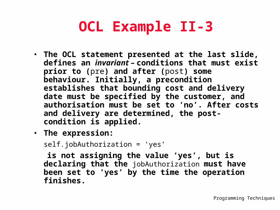
• The OCL statement presented at the last slide, defines an invariant – conditions that must exist prior to (pre) and after (post) some behaviour. Initially, a precondition establishes that bounding cost and delivery date must be specified by the customer, and authorisation must be set to ‘no’. After costs and delivery are determined, the post-condition is applied.
• The expression:
self.jobAuthorization = ‘yes’
is not assigning the value ‘yes’, but is declaring that the jobAuthorization must have been set to ‘yes’ by the time the operation finishes.

Programming Techniques
5. Conventional or Structured Component Design
• Structured programming is a design technique that constrains logic flow to three constructs; sequence, condition and repetition.
• Each block of code has a single entry at the top • Each block of code has a single exit at the bottom • Only three control structures are required: sequence,
condition (if-then-else), and repetition (looping) • Reduces program complexity by enhancing readability,
testability, and maintainability
Programming Techniques
Structured Programmingfor Procedural Design
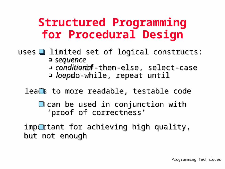
uses a limited set of logical constructs:uses a limited set of logical constructs: sequencesequence conditionalconditional — — if-then-else, select-caseif-then-else, select-case loopsloops — — do-while, repeat untildo-while, repeat until
leads to more readable, testable codeleads to more readable, testable code
important for achieving high quality, important for achieving high quality, but not enoughbut not enough
can be used in conjunction with ‘proof can be used in conjunction with ‘proof of correctness’of correctness’

Programming Techniques
A Structured Procedural Design
a
x1
x2b
3x
4
5
c
d
ef
g
x
x
add a condition Z, if true, exit the program

Programming Techniques
Design Notation
• Graphical Design Notation - flowcharts - arrows for flow of control, diamonds for decisions, rectangles for processes
• Tabular Design Notation - decision tables - subsets of system conditions and actions are associated with each other to define the rules for processing inputs and events
• Program Design Language (PDL) - structured English or pseudocode used to describe processing details

Programming Techniques
5.1.Graphical Design Notation
• UML activity diagrams – descendent of flowcharts
• UML activity diagrams can be used in lieu of flowcharts
• Flowcharts – earlier pictorial design representation:
- box – indicate a processing step
- diamond – represents a logical condition
- arrows – show the flow of control

Programming Techniques
Flowchart Constructs
• Sequence – represented as two processing boxes connected by line (arrow) of control
• Condition, also called (if-then-else) – depicted as a decision diamond that if true, causes then-part processing to occur, and if-else, invokes else-part processing.
• Repetition is represented using two slightly different forms:
- do-while tests a condition and executes a loop task repetitively as long as the condition holds true
- repeat until executes the loop task first, then tests a condition and repeats the task until the condition fails.

Programming Techniques
Flowchart Constructs
Programming Techniques
5.2. Tabular Design Notation
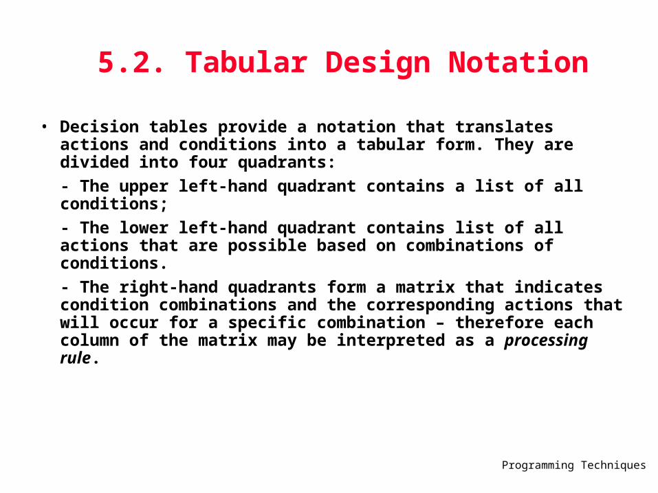
• Decision tables provide a notation that translates actions and conditions into a tabular form. They are divided into four quadrants:
- The upper left-hand quadrant contains a list of all conditions;
- The lower left-hand quadrant contains list of all actions that are possible based on combinations of conditions.
- The right-hand quadrants form a matrix that indicates condition combinations and the corresponding actions that will occur for a specific combination – therefore each column of the matrix may be interpreted as a processing rule.

Programming Techniques
How do I build a Decision Table ?
• 1. List all actions that can be associated with a specific procedure (or module)
• 2. List all conditions (or decisions made) during execution of the procedure.
• 3. Associate specific sets of conditions with specific actions, eliminating impossible combinations of conditions; alternatively, develop every possible permutation of conditions.
• 4. Define rules by indicating what action(s) occurs for a set of conditions.

Programming Techniques
Decision Table Example
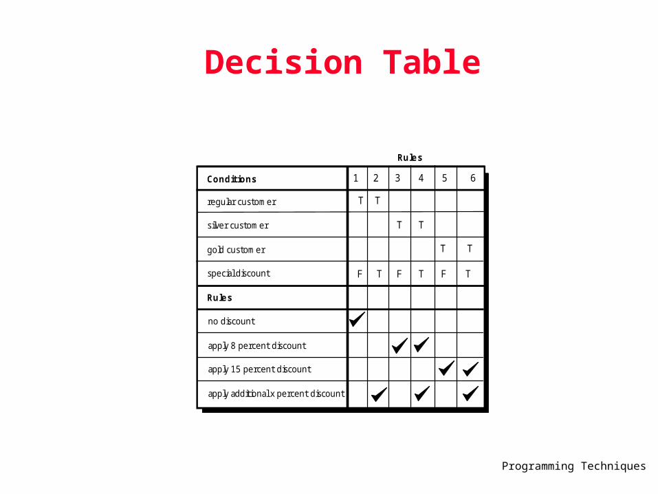
Print shop use case:Three types of customers are defined: a regular customer, a silver customer, and a gold customer, depending by the amount of business the customer does with the print shop over a 12-month period.A regular customer receives normal print rates and delivery.A silver customer gets an 8 percent discount on all quotes and is placed ahead of all regular customers in the job queue. A gold customer gets a 15 percent reduction in quoted prices and is placed ahead of both regular and silver customers in the job queue.À special discount of x percent I addition to other discounts can be applied to any customer’s quote at the discretion of management.
Next Figure:Illustrates a decision table representation of the preceding use case.Each of the six rules indicates one of six viable conditions.
Programming Techniques
Decision Table
Conditions
regular customer
silver customer
gold customer
special discount
Rules
no discount
apply 8 percent discount
apply 15 percent discount
apply additional x percent discount
T
F
T
T
T
T
T
F
1 3 5 64
F
T T
T
2
Rules
Programming Techniques
5.3. Program Design Language (PDL) Characteristics
• PDL – also called structured English or pseudocode
• Fixed syntax with keywords providing for representation of all structured constructs, data declarations, and module definitions
• Free syntax of natural language for describing processing features
• Data declaration facilities for simple and complex data structures
• Subprogram definition and invocation facilities

Programming Techniques
PDL
• Not a programming language
• Uses narrative text – can not be compiled
• Tools can translate PDL into a programming language ‘skeleton’ and/or a graphical representation (e.g. a flowchart) of design

Programming Techniques
Why PDL?
• Can be a derivative of the Higher Order Languages (HOL) of choice (ADA, C, or Java)
• Machine readable and processable
• Can be embedded with source code, therefore easier to maintain
• Can be represented in great detail, if designer and coder are different
• Easy to review

Programming Techniques
PDL
if-then-else
if condition x then process a; else process b; endif
PDL
easy to combine with source code machine readable, no need for graphics input graphics can be generated from PDL enables declaration of data as well as procedure easier to maintain

Programming Techniques
PDL Sample – Alarm Management Component
Component alarmManagement;The intent of this component is to manage control panel switches and input from sensors by type and to act
on any alarm condition that is encountered.set default values for systemStatus (returned value), all data itemsinitialize all system ports and reset all hardwarecheck controlPanelSwitches (cps) if cps = ‘test’ then invoke alarm set to ‘on’ if cps = ‘alarmOff’ then invoke alarm set to ‘off’
.
.
. default for cps = nonereset all signalValues and switchesdo for all sensors invoke checkSensor procedure returning signalValue if signalValue > bound [alarmType] then phone.massage = message [alarmType] set alarmBell to ‘on’ for alarmTimeSeconds
set system status = ‘alarmCondition’ parbegin invoke alarm procedure with ‘on’, alarmTimeSeconds; invoke phone procedure set to alarmType, phoneNumber
parend else skip endif enddoforend alarmManagement

Programming Techniques
5.4. Design Notation Assessment Criteria
• Modularity - notation supports development of modular software • Overall simplicity - easy to learn, easy to use, easy to write • Ease of editing - easy to modify design representation when changes are
necessary • Machine readability - notation can be input directly into a computer-based
development system • Maintainability - maintenance of the configuration usually involves maintenance of
the procedural design representation • Structure enforcement - enforces the use of structured programming constructs • Automatic processing - allows the designer to verify the correctness and quality of
the design • Data representation - ability to represent local and global data directly • Logic verification - automatic logic verification improves testing adequacy • Easily converted to program source code (makes code generation quicker)

Programming Techniques
2005F
Instructor
John D Lin - [email protected]
Lectures
Tues & Thurs 10:00-11:30 RM. 100, Lower Block