Embed Size (px)
Citation preview

PROGRAMMING OF FINITE ELEMENT METHODS IN MATLAB
LONG CHEN
We shall discuss how to implement the linear finite element method for solving the Pois-son equation. We begin with the data structure to represent the triangulation and boundaryconditions, introduce the sparse matrix, and then discuss the assembling process. Since weuse MATLAB as the programming language, we pay attention to an efficient programmingstyle using sparse matrices in MATLAB.
1. DATA STRUCTURE OF TRIANGULATION
We shall discuss the data structure to represent triangulations and boundary conditions.
1.1. Mesh data structure. The matrices node(1:N,1:d) and elem(1:NT,1:d+1) areused to represent a d-dimensional triangulation embedded in Rd, where N is the numberof vertices and NT is the number of elements. These two matrices represent two differentstructure of a triangulation: elem for the topology and node for the geometric embedding.
The matrix elem represents a set of abstract simplices. The index set 1, 2, . . . , N iscalled the global index set of vertices. Here an vertex is thought as an abstract entity. Fora simplex t, 1, 2, . . . , d + 1 is the local index set of t. The matrix elem is the mapping(pointer) from the local index to the global one, i.e., elem(t,1:d+1) records the globalindices of d + 1 vertices which form the abstract d-simplex t. Note that any permutationof vertices of a simplex will represent the same abstract simplex.
The matrix node gives the geometric realization of the simplicial complex. For ex-ample, for a 2-D triangulation, node(k,1:2) contain x- and y-coordinates of the k-thnodes.
The geometric realization introduces an ordering of the simplex. For each elem(t,:),we shall always order the vertices of a simplex such that the signed area is positive. Thatis in 2-D, three vertices of a triangle is ordered counter-clockwise and in 3-D, the orderingof vertices follows the right-hand rule.
Remark 1.1. Even with the orientation requirement, certain permutation of vertices is stillallowed. Similarly any labeling of simplices in the triangulation, i.e. any permutation of thefirst index of elem matrix will represent the same triangulation. The ordering of simplexesand vertices will be used to facilitate the implementation of the local mesh refinement andcoarsening.
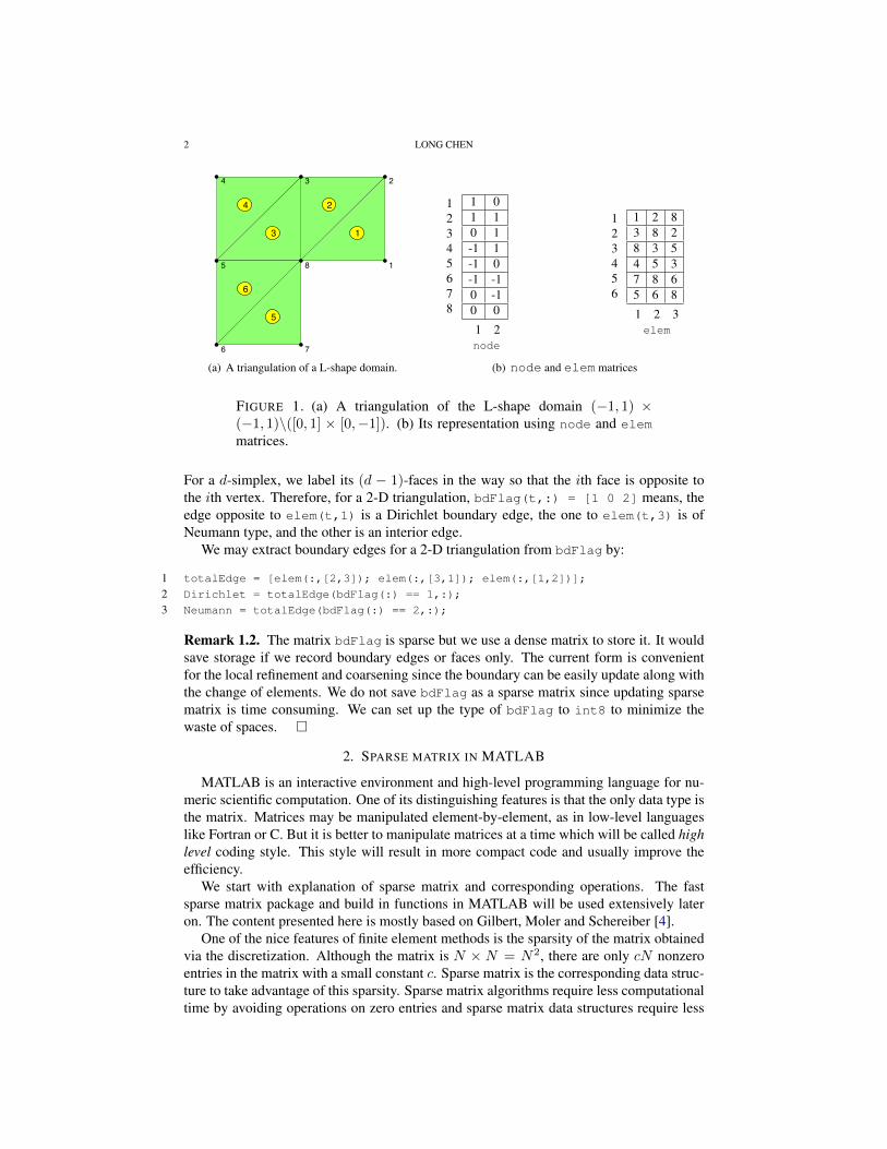
As an example, node and elem matrices for the triangulation of the L-shape domain(−1, 1)× (−1, 1)\([0, 1]× [0,−1]) are given in the Figure 1 (a) and (b).
1.2. Boundary condition. We use bdFlag(1:NT,1:d+1) to record the type of boundarysides (edges in 2-D and faces in 3-D). The value is the type of boundary condition:
• 0 for non-boundary sides;• 1 for the first type, i.e., Dirichlet boundary;• 2 for the second type, i.e., Neumann boundary;• 3 for the third type, i.e., Robin boundary.
1
2 LONG CHEN
1
234
5
6 7
8
1
2
3
4
5
6
(a) A triangulation of a L-shape domain.
8 LONG CHEN
1
234
5
6 7
8
1
2
3
4
5
6
FIGURE 3. A triangulation of a L-shape domain.
12345678
1 01 10 1-1 1-1 0-1 -10 -10 0
1 2node
123456
1 2 83 8 28 3 54 5 37 8 65 6 8
1 2 3elem
123456789
10111213
1 21 82 32 83 43 53 84 55 65 86 76 87 8
1 2edge
TABLE 1. node,elem and edge matrices for the L-shape domain in Figure 3.
3.3.2. Auxiliary data structure for 2-D triangulation. We shall discuss how to extract the topologicalor combinatorial structure of a triangulation by using elem array only. The combinatorial structure willbenefit the finite element implementation.
edge. We first complete the 2-D simplicial complex by constructing the 1-dimensional simplex. In thematrix edge(1:NE,1:2), the first and second rows contain indices of the starting and ending points.The column is sorted in the way that for the k-th edge, edge(k,1)<edge(k,2). The following codewill generate an edge matrix.
1 totalEdge = sort([elem(:,[1,2]); elem(:,[1,3]); elem(:,[2,3])],2);
2 [i,j,s] = find(sparse(totalEdge(:,2),totalEdge(:,1),1));
3 edge = [j,i]; bdEdge = [j(s==1),i(s==1)];
The first line collect all edges from the set of triangles and sort the column such that totalEdge(k,1)<totalEdge(k,2). The interior edges are repeated twice in totalEdge. We use the summationproperty of sparse command to merge the duplicated indices. The nonzero vector s takes values 1 (forboundary edges) or 2 (for interior edges). We then use find to return the nonzero indices which forms
(b) node and elem matrices
FIGURE 1. (a) A triangulation of the L-shape domain (−1, 1) ×(−1, 1)\([0, 1] × [0,−1]). (b) Its representation using node and elem
matrices.
For a d-simplex, we label its (d − 1)-faces in the way so that the ith face is opposite tothe ith vertex. Therefore, for a 2-D triangulation, bdFlag(t,:) = [1 0 2] means, theedge opposite to elem(t,1) is a Dirichlet boundary edge, the one to elem(t,3) is ofNeumann type, and the other is an interior edge.
We may extract boundary edges for a 2-D triangulation from bdFlag by:
1 totalEdge = [elem(:,[2,3]); elem(:,[3,1]); elem(:,[1,2])];
2 Dirichlet = totalEdge(bdFlag(:) == 1,:);
3 Neumann = totalEdge(bdFlag(:) == 2,:);
Remark 1.2. The matrix bdFlag is sparse but we use a dense matrix to store it. It wouldsave storage if we record boundary edges or faces only. The current form is convenientfor the local refinement and coarsening since the boundary can be easily update along withthe change of elements. We do not save bdFlag as a sparse matrix since updating sparsematrix is time consuming. We can set up the type of bdFlag to int8 to minimize thewaste of spaces.
2. SPARSE MATRIX IN MATLAB
MATLAB is an interactive environment and high-level programming language for nu-meric scientific computation. One of its distinguishing features is that the only data type isthe matrix. Matrices may be manipulated element-by-element, as in low-level languageslike Fortran or C. But it is better to manipulate matrices at a time which will be called highlevel coding style. This style will result in more compact code and usually improve theefficiency.
We start with explanation of sparse matrix and corresponding operations. The fastsparse matrix package and build in functions in MATLAB will be used extensively lateron. The content presented here is mostly based on Gilbert, Moler and Schereiber [4].
One of the nice features of finite element methods is the sparsity of the matrix obtainedvia the discretization. Although the matrix is N × N = N2, there are only cN nonzeroentries in the matrix with a small constant c. Sparse matrix is the corresponding data struc-ture to take advantage of this sparsity. Sparse matrix algorithms require less computationaltime by avoiding operations on zero entries and sparse matrix data structures require less

PROGRAMMING OF FINITE ELEMENT METHODS IN MATLAB 3
computer memory by not storing many zero entries. We refer to the book [6] for detaileddescription on sparse matrix data structure and [7] for a quick introduction on popular datastructures of sparse matrix. In particular, the sparse matrix data structure and operationshas been added to MATLAB by Gilbert, Moler and Schereiber and documented in [4].
2.1. Storage scheme. There are different types of data structures for the sparse matrix.All of them share the same basic idea: use a single array to store all nonzero entries andtwo additional integer arrays to store the indices of nonzero entries.
An intutive scheme, known as coordinate format, is to store both the row and columnindices. In the sequel, we suppose A is a m × n matrix containing only nnz nonzeroelements. Let us look at the following simple example:
(1) A =
1 0 00 2 40 0 00 9 0
, i =
1242
, j =
1223
, s =
1294
.In this example, i vector stores row indices of non-zeros, j column indices, and s the valueof non-zeros. All three vectors have the same length nnz. The two indices vectors i and jcontains redundant information. We can compress the column index vector j to a columnpointer vector with length n + 1. The value j(k) is the pointer to the beginning of k-thcolumn in the vector of i and s, and j(n + 1) = nnz. For example, in CSC formate,the vector to store the column pointer will be j = [ 1 3 4 ]t. This scheme is knownas Compressed Sparse Column (CSC) scheme and is used in MATLAB sparse matricespackage. Comparing with coordinate formate, CSC formate saves storage for nnz−n− 1integers which could be nonnegligilble when the number of nonzero is much larger thanthat of the column. In CSC formate it is efficient to extract a column of a sparse matrix.For example, the k-th column of a sparse matrix can be build from the index vector i andthe value vector s ranging from j(k) to j(k + 1)− 1. There is no need of searching indexarrays. An algorithm that builds up a sparse matrix one column at a time can be alsoimplemented efficiently [4].
Remark 2.1. CSC is the internal representation of sparse matrices in MATLAB. For userconvenience, the coordinate scheme is presented as the interface. This allows users tocreate and decompose sparse matrices in a more straightforward way.
Comparing with the dense matrix, the sparse matrix lost the direct relation betweenthe index (i,j) and the physical location to store the value A(i,j). The accessing andmanipulating matrices one element at a time requires the searching of the index vectors tofind such nonzero entry. It takes time at least proportional to the logarithm of the lengthof the column; inserting or removing a nonzero may require extensive data movement [4].Therefore, do not manipulate a sparse matrix element-by-element in a large for loop inMATLAB.
Due to the lost of the link between the index and the value of entries, the operationson sparse matrices is delicate. One needs to code specific subroutines for standard matrixoperations: matrix times vector, addition of two sparse matrices, and transpose of sparsematrices etc. Since some operations will change the sparse pattern, typically there is apriori loop to set up the nonzero pattern of the resulting sparse matrix. Good sparse matrixalgorithms should follow the “time is proportional to flops” rule [4]: The time required fora sparse matrix operation should be proportional to the number of arithmetic operations onnonzero quantities. The sparse package in MATLAB follows this rule; See [4] for details.

4 LONG CHEN
2.2. Create and decompose sparse matrix. To create a sparse matrix, we first form i, jand s vectors, i.e., a list of nonzero entries and their indices, and then call the functionsparse using i, j, s as input. Several alternative forms of sparse (with more than oneargument) allow this. The most commonly used one is
A = sparse(i,j,s,m,n).This call generates an m × n sparse matrix, having one nonzero for each entry in the
vectors i, j, and s such that A(i(k), j(k)) = s(k). The first three arguments all have thesame length. However, the indices in i and j need not be given in any particular order andcould have duplications. If a pair of indices occurs more than once in i and j, sparse addsthe corresponding values of s together. This nice summation property is very useful for theassembling procedure in finite element computation.
The function [i,j,s]=find(A) is the inverse of sparse function. It will extract thenonzero elements together with their indices. The indices set (i, j) are sorted in columnmajor order and thus the nonzero A(i,j) is sorted in lexicographic order of (j,i) not(i,j). See the example in (1).
Remark 2.2. There is a similar command accumarray to create a dense matrix A fromindices and values. It is slightly different from sparse. The index [i j] should be pairedtogether to form a subscript vectors. So is the dimension [m n]. Since the accessing of asingle element in a dense matrix is much faster than that in a sparse matrix, when m or nis small, say n = 1, it is better to use accumarray instead of sparse. A most commonlyused command is
accumarray([i j], s, [m n]).
3. ASSEMBLING OF MATRIX EQUATION
In this section, we discuss how to obtain the matrix equation for the linear finite elementmethod of solving the Poisson equation
(2) −∆u = f in Ω, u = gD on ΓD, ∇u · n = gN on ΓN ,
where ∂Ω = ΓD ∪ ΓN and ΓD ∩ ΓN = ∅. We assume ΓD is closed and ΓN open.Denoted byH1
g,D(Ω) = v ∈ L2(Ω),∇v ∈ L2(Ω) and v|ΓD = gD. Using integrationby parts, the weak form of the Poisson equation (2) is: find u ∈ H1
g,D(Ω) such that
(3) a(u, v) :=
∫Ω
∇u · ∇v dx =
∫Ω
fv dx +
∫ΓN
gNv dS for all v ∈ H10,D(Ω).
Let T be a triangulation of Ω. We define the linear finite element space on T as
VT = v ∈ C(Ω) : v|τ ∈ P1,∀τ ∈ T ,whereP1 is the space of linear polynomials. For each vertex vi of T , let φi be the piecewiselinear function such that φi(vi) = 1 and φi(vj) = 0 if j 6= i. Then it is easy to seeVT is spanned by φiNi=1. The linear finite element method for solving (2) is to findu ∈ VT ∩H1
g,D(Ω) such that (3) holds for all v ∈ VT ∩H10,D(Ω).
We shall discuss an efficient way to obtain the algebraic equation. It is an improvedversion, for the sake of efficiency, of that in the paper [1].
3.1. Assembling the stiffness matrix. For a function v ∈ VT , there is a unique represen-tation: v =
∑Ni=1 viφi. We define an isomorphism VT ∼= RN by
(4) v =
N∑i=1
viφi ←→ v = (v1, · · · , vN )t,
PROGRAMMING OF FINITE ELEMENT METHODS IN MATLAB 5
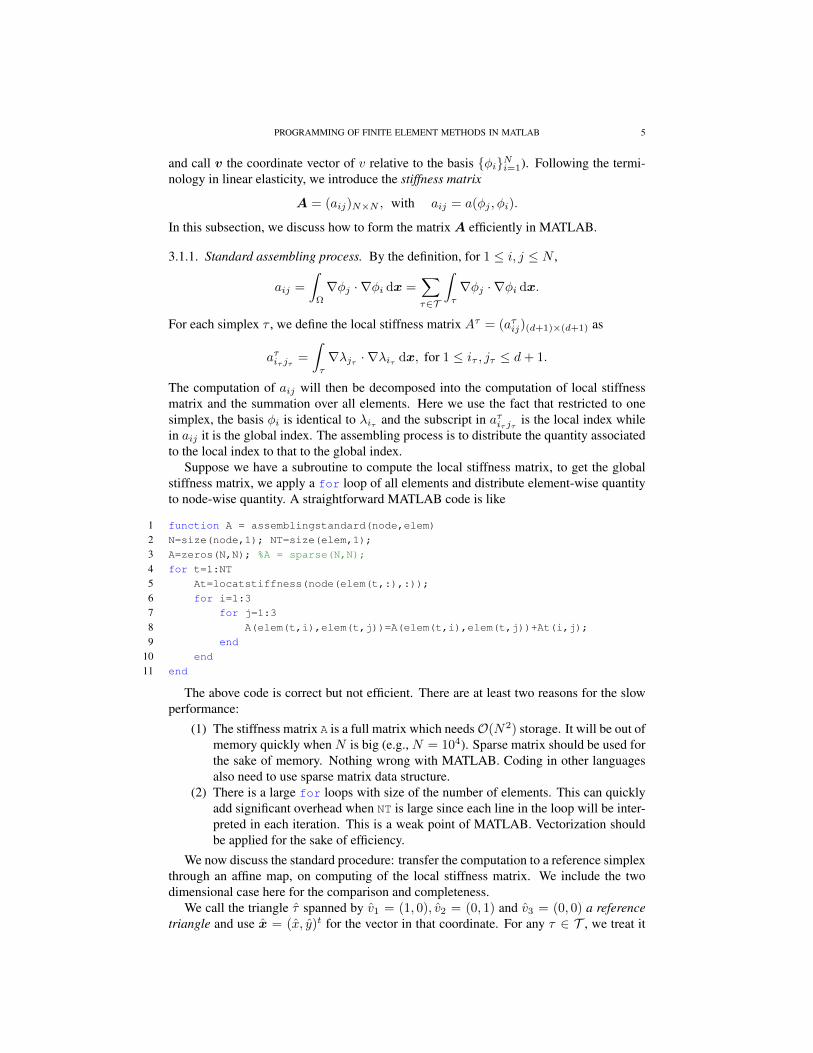
and call v the coordinate vector of v relative to the basis φiNi=1). Following the termi-nology in linear elasticity, we introduce the stiffness matrix
A = (aij)N×N , with aij = a(φj , φi).
In this subsection, we discuss how to form the matrix A efficiently in MATLAB.
3.1.1. Standard assembling process. By the definition, for 1 ≤ i, j ≤ N ,
aij =
∫Ω
∇φj · ∇φi dx =∑τ∈T
∫τ
∇φj · ∇φi dx.
For each simplex τ , we define the local stiffness matrix Aτ = (aτij)(d+1)×(d+1) as
aτiτ jτ =
∫τ
∇λjτ · ∇λiτ dx, for 1 ≤ iτ , jτ ≤ d+ 1.
The computation of aij will then be decomposed into the computation of local stiffnessmatrix and the summation over all elements. Here we use the fact that restricted to onesimplex, the basis φi is identical to λiτ and the subscript in aτiτ jτ is the local index whilein aij it is the global index. The assembling process is to distribute the quantity associatedto the local index to that to the global index.
Suppose we have a subroutine to compute the local stiffness matrix, to get the globalstiffness matrix, we apply a for loop of all elements and distribute element-wise quantityto node-wise quantity. A straightforward MATLAB code is like
1 function A = assemblingstandard(node,elem)
2 N=size(node,1); NT=size(elem,1);
3 A=zeros(N,N); %A = sparse(N,N);
4 for t=1:NT
5 At=locatstiffness(node(elem(t,:),:));
6 for i=1:3
7 for j=1:3
8 A(elem(t,i),elem(t,j))=A(elem(t,i),elem(t,j))+At(i,j);
9 end
10 end
11 end
The above code is correct but not efficient. There are at least two reasons for the slowperformance:
(1) The stiffness matrix A is a full matrix which needsO(N2) storage. It will be out ofmemory quickly when N is big (e.g., N = 104). Sparse matrix should be used forthe sake of memory. Nothing wrong with MATLAB. Coding in other languagesalso need to use sparse matrix data structure.
(2) There is a large for loops with size of the number of elements. This can quicklyadd significant overhead when NT is large since each line in the loop will be inter-preted in each iteration. This is a weak point of MATLAB. Vectorization shouldbe applied for the sake of efficiency.
We now discuss the standard procedure: transfer the computation to a reference simplexthrough an affine map, on computing of the local stiffness matrix. We include the twodimensional case here for the comparison and completeness.
We call the triangle τ spanned by v1 = (1, 0), v2 = (0, 1) and v3 = (0, 0) a referencetriangle and use x = (x, y)t for the vector in that coordinate. For any τ ∈ T , we treat it

6 LONG CHEN
as the image of τ under an affine map: F : τ → τ . One of such affine map is to match thelocal indices of three vertices, i.e., F (vi) = vi, i = 1, 2, 3:
F (x) = Bt(x) + c,
where
B =
[x1 − x3 y1 − y3
x2 − x3 y2 − y3
], and c = (x3, y3)t.
We define u(x) = u(F (x)). Then ∇u = B∇u and dxdy = |det(B)|dxdy. We changethe computation of the integral in τ to τ by∫
τ
∇λi · ∇λjdxdy =
∫τ
(B−1∇λi) · (B−1∇λj)|det(B)|dxdy
=1
2|det(B)|(B−1∇λi) · (B−1∇λj).
In the reference triangle, λ1 = x, λ2 = y and λ3 = 1− x− y. Thus
∇λ1 =
[10
], ∇λ2 =
[01
], and ∇λ3 =
[−1−1
].
We then end with the following subroutine [1] to compute the local stiffness matrix in onetriangle τ .
1 function [At,area] = localstiffness(p)
2 At = zeros(3,3);
3 B = [p(1,:)-p(3,:); p(2,:)-p(3,:)];
4 G = [[1,0]’,[0,1]’,[-1,-1]’];
5 area = 0.5*abs(det(B));
6 for i = 1:3
7 for j = 1:3
8 At(i,j) = area*((B\G(:,i))’*(B\G(:,j)));
9 end
10 end
The advantage of this approach is that by modifying the subroutine localstiffness,one can easily adapt to new elements and new equations.
3.1.2. Assembling using sparse matrix. A straightforward modification of using sparsematrix is to replace the line 3 in the subroutine assemblingstandard by A=sparse(N,N).Then MATLAB will use sparse matrix to store A and thus we solve the problem of stor-age. Thanks to the sparse matrix package in MATLAB, we can still access and operate thesparse A use standard format and thus keep other lines of code unchanged.
However, as we mentioned before, updating one single element of a sparse matrixin a large loop is very expensive since the nonzero indices and values vectors will bereformed and a large of data movement is involved. Therefore the code in line 8 ofassemblingstandard will dominate the whole computation procedure. In this example,numerical experiments show that the subroutine assemblingstandard will take O(N2)time.
We should use sparse command to form the sparse matrix. The following subroutineis suggested by T. Davis [2].
1 function A = assemblingsparse(node,elem)
2 N = size(node,1); NT = size(elem,1);
3 i = zeros(9*NT,1); j = zeros(9*NT,1); s = zeros(9*NT,1);

PROGRAMMING OF FINITE ELEMENT METHODS IN MATLAB 7
4 index = 0;
5 for t = 1:NT
6 At = localstiffness(node(elem(t,:),:));
7 for ti = 1:3
8 for tj = 1:3
9 index = index + 1;
10 i(index) = elem(t,ti);
11 j(index) = elem(t,tj);
12 s(index) = At(ti,tj);
13 end
14 end
15 end
16 A = sparse(i, j, s, N, N);
In the subroutine assemblingsparse, we first record a list of index and nonzero en-tries in the loop and use build-in function sparse to form the sparse matrix outside theloop. By doing in this way, we avoid updating a sparse matrix inside a large loop. The sub-routine assemblingsparse is faster than assemblingstandard. Numerical test showsthe computational complexity is improved fromO(N2) toO(N logN). This simple mod-ification is recommended when translating C or Fortran codes into MATLAB.
3.1.3. Vectorization of assembling. There is still a large loop in the subroutine aseemblingsparse.We shall use the vectorization technique to avoid the outer large for loop.
Given a d-simplex τ , recall that the barycentric coordinates λj(x), j = 1, · · · , d + 1are linear functions of x. If the j-th vertices of a simplex τ is the k-th vertex, then the hatbasis function φk restricted to a simplex τ will coincide with the barycentric coordinateλj . Note that the index j = 1, · · · , d + 1 is the local index set for the vertices of τ , whilek = 1, · · · , N is the global index set of all vertices in the triangulation.
We shall derive a formula for∇λi, i = 1, · · · , d+1. Let Fi denote the (d−1)-face of τopposite to the ith-vertex. Since λi(x) = 0 for all x ∈ Fi, and λi(x) is an affine functionof x, the gradient ∇λi is a normal vector of the face Fi with magnitude 1/hi, where hi isthe distance from the vertex xi to the face Fi. Using the relation |τ | = 1
d |Fi|hi, we endwith the following formula
(5) ∇λi =1
d! |τ |ni,
where ni is an inward normal vector of the face Fi with magnitude ‖ni‖ = (d − 1)!|Fi|.Therefore
aτij =
∫τ
∇λi · ∇λj dx =1
d!2|τ |ni · nj .
In 2-D, the scaled normal vector ni can be easily computed by a rotation of the edgevector. For a triangle spanned by x1,x2 and x3, we define li = xi+1 − xi−1 where thesubscript is 3-cyclic. For a vector v = (x, y), we denoted by v⊥ = (−y, x). Then ni = l⊥iand ni · nj = li · lj . The edge vector li for all triangles can be computed as a matrix andwill be used to compute the area of all triangles.
We then end with the following compact and efficient code for the assembling of stiff-ness matrix in two dimensions.
1 function A = assembling(node,elem)
2 N = size(node,1); NT = size(elem,1);
3 ii = zeros(9*NT,1); jj = zeros(9*NT,1); sA = zeros(9*NT,1);
4 ve(:,:,3) = node(elem(:,2),:)-node(elem(:,1),:);

8 LONG CHEN
5 ve(:,:,1) = node(elem(:,3),:)-node(elem(:,2),:);
6 ve(:,:,2) = node(elem(:,1),:)-node(elem(:,3),:);
7 area = 0.5*abs(-ve(:,1,3).*ve(:,2,2)+ve(:,2,3).*ve(:,1,2));
8 index = 0;
9 for i = 1:3
10 for j = 1:3
11 ii(index+1:index+NT) = elem(:,i);
12 jj(index+1:index+NT) = elem(:,j);
13 sA(index+1:index+NT) = dot(ve(:,:,i),ve(:,:,j),2)./(4*area);
14 index = index + NT;
15 end
16 end
17 A = sparse(ii,jj,sA,N,N);
Remark 3.1. One can further improve the efficiency of the above subroutine by using thesymmetry of the matrix. For example, the inner loop can be changed to for j = i:3.
In 3-D, the scaled normal vector ni can be computed by the cross product of two edgevectors. We list the code below and explain it briefly.
1 function A = assembling3(node,elem)
2 N = size(node,1); NT = size(elem,1);
3 ii = zeros(16*NT,1); jj = zeros(16*NT,1); sA = zeros(16*NT,1);
4 face = [elem(:,[2 4 3]);elem(:,[1 3 4]);elem(:, [1 4 2]);elem(:, [1 2 3])];
5 v12 = node(face(:,2),:)-node(face(:,1),:);
6 v13 = node(face(:,3),:)-node(face(:,1),:);
7 allNormal = cross(v12,v13,2);
8 normal(1:NT,:,4) = allNormal(3*NT+1:4*NT,:);
9 normal(1:NT,:,1) = allNormal(1:NT,:);
10 normal(1:NT,:,2) = allNormal(NT+1:2*NT,:);
11 normal(1:NT,:,3) = allNormal(2*NT+1:3*NT,:);
12 v12 = v12(3*NT+1:4*NT,:);
13 v13 = v13(3*NT+1:4*NT,:);
14 v14 = node(elem(:,4),:)-node(elem(:,1),:);
15 volume = dot(cross(v12,v13,2),v14,2)/6;
16 index = 0;
17 for i = 1:4
18 for j = 1:4
19 ii(index+1:index+NT) = elem(:,i);
20 jj(index+1:index+NT) = elem(:,j);
21 sA(index+1:index+NT) = dot(normal(:,:,i),normal(:,:,j),2)./(36*volume);
22 index = index + NT;
23 end
24 end
25 A = sparse(ii,jj,sA,N,N);
The code in line 4 will collect all faces of the tetrahedron mesh. So the face is of dimen-sion 4NT×3. For each face, we form two edge vectors v12 and v13, and apply the crossproduct to obtain the scaled normal vector in allNormal matrix. The code in line 8-11 isto reshape the 4NT×3 normal vector to a NT×3×4 matrix. Note that in line 8, we assignthe value to normal(:,:,4) first such that the MATLAB will allocate enough memoryfor the array normal when creating it. Line 15 use the mix product of three edge vectors tocompute the volume and line 19–22 is similar to 2-D case. The introduction of the scalednormal vector ni simplify the implementation and enable us to vectorize the code.

PROGRAMMING OF FINITE ELEMENT METHODS IN MATLAB 9
3.2. Right hand side. We define the vector f = (f1, · · · , fN )t by fi =∫
Ωfφi, where
φi is the hat basis at the vertex vi. For quasi-uniform meshes, all simplices are around thesame size, while in adaptive finite element method, some elements with large mesh sizecould remain unchanged. Therefore, although the 1-point quadrature is adequate for thelinear element on quasi-uniform meshes, to reduce the error introduced by the numericalquadrature, we compute the load term
∫Ωfφi by 3-points quadrature rule in 2-D and 4-
points rule in 3-D. General order numerical quadrature will be discussed in the next section.We list the 2-D code below as an example to emphasize that the command accumarray
is used to avoid the slow for loop over all elements.
1 mid1 = (node(elem(:,2),:)+node(elem(:,3),:))/2;
2 mid2 = (node(elem(:,3),:)+node(elem(:,1),:))/2;
3 mid3 = (node(elem(:,1),:)+node(elem(:,2),:))/2;
4 bt1 = area.*(f(mid2)+f(mid3))/6;
5 bt2 = area.*(f(mid3)+f(mid1))/6;
6 bt3 = area.*(f(mid1)+f(mid2))/6;
7 b = accumarray(elem(:),[bt1;bt2;bt3],[N 1]);
3.3. Boundary condition. We list the code for 2-D case and briefly explain it for thecompleteness. Recall that Dirichlet and Neumann are boundary edges which can befound using bdFlag.
1 %-------------------- Dirichlet boundary conditions------------------------
2 isBdNode = false(N,1);
3 isBdNode(Dirichlet) = true;
4 bdNode = find(isBdNode);
5 freeNode = find(˜isBdNode);
6 u = zeros(N,1);
7 u(bdNode) = g_D(node(bdNode,:));
8 b = b - A*u;
9 %-------------------- Neumann boundary conditions -------------------------
10 if (˜isempty(Neumann))
11 Nve = node(Neumann(:,1),:) - node(Neumann(:,2),:);
12 edgeLength = sqrt(sum(Nve.ˆ2,2));
13 mid = (node(Neumann(:,1),:) + node(Neumann(:,2),:))/2;
14 b = b + accumarray([Neumann(:),ones(2*size(Neumann,1),1)], ...
15 repmat(edgeLength.*g_N(mid)/2,2,1),[N,1]);
16 end
Line 2-4 will find all Dirichlet boundary nodes. The Dirichlet boundary condition isposed by assign the function values at Dirichlet boundary nodes bdNode. It could befound by using bdNode = unique(Dirichlet) but unique is very costly. So we uselogic array to find all nodes on the Dirichlet boundary, denoted by bdNode. The othernodes will be denoted by freeNode.
The vector u is initialized as zero vector. Therefore after line 7, the vector u will rep-resent a function uD ∈ Hg,D. Writing u = u + uD, the problem (3) is equivalent tofinding u ∈ VT ∩ H1
0 (Ω) such that a(u, v) = (f, v) − a(uD, v) + (gN , v)ΓN for allv ∈ VT ∩ H1
0 (Ω). The modification of the right hand side (f, v) − a(uD, v) is realizedby the code b=b-A*u in line 8. The boundary integral involving the Neumann boundarypart is computed in line 11–15 using the middle point quadrature. Note that it is vectorizedusing accumarray.

10 LONG CHEN
Since uD and u use disjoint nodes set, one vector u is used to represent both. Theaddition of u+uD is realized by assign values to different index sets of the same vector u.We have assigned the value to boundary nodes in line 5. We will compute u, i.e., the valueat other nodes (denoted by freeNode), by
(6) u(freeNode)=A(freeNode,freeNode)\b(freeNode).
For the Poisson equation with Neumann boundary condition
−∆u = f in Ω,∂u
∂n= g on Γ,
there are two issues on the well posedness of the continuous problem:(1) solutions are not unique. If u is a solution of Neumann problem, so is u + c for
any constant c ∈ R. One more constraint is needed to determine this constant. Acommon choice is
∫Ωudx = 0.
(2) a compatible condition for the existence of a solution. There is a compatible con-dition for f and g:
(7) −∫
Ω
f dx =
∫Ω
∆udx =
∫∂Ω
∂u
∂ndS =
∫∂Ω
g dS.
We then discuss the consequence of these two issues in the discretization. The stiffnessmatrix A is symmetric but only semi-definite. The kernel of A consists of constant vectors,i.e, the rank of A is N-1. Then Au=b is solvable if and only if
(8) mean(b)=0
which is the discrete compatible condition. If the integral is computed exactly, accordingto (7), (8) should hold in the discrete case. But since we use numerical quadrature toapproximate the integral, (8) may hold accurately. We can enforce (8) by the modificationb = b - mean(b).
To deal with the constant kernel of A, we can simply set freeNode=2:N and then use(6) to find values of u at freeNode. Since solution u is unique up to a constant, afterwardswe need to modify u to satisfy certain constraint. For example, to impose the zero average,i.e.,
∫Ωudx = 0/|Ω|, we could use the following code:
1 c = sum(mean(u(elem),2).*area)/sum(area);
2 u = u - c;
The H1 error will not affect by the constant shift but when computing L2 error, make surethe exact solution will satisfy the same constraint.
4. NUMERICAL QUADRATURE
In the implementation, we need to compute various integrals on a simplex. In thissection, we will present several numerical quadrature rules for simplexes in 1, 2 and 3dimensions.
The numerical quadrature is to approximate an integral by weighted average of functionvalues at sampling points pi:∫
τ
f(x) dx ≈ In(f) :=
n∑i=1
f(pi)wi|τ |.
The order of a numerical quadrature is defined as the largest integer k such that∫f =
In(f) when f is a polynomial of degree less than equal to k.

PROGRAMMING OF FINITE ELEMENT METHODS IN MATLAB 11
A numerical quadrature is determined by the quadrature points and corresponding weight:(pi, wi), i = 1, . . . , n. For a d-simplex τ , let xi, i = 1, . . . , d + 1 be vertices of τ . Thesimplest one is the one point rule:
I1(f) = f(cτ )|τ |, cτ =1
d+ 1
d+1∑i=1
xi.
A very popular one is the trapezoidal rule:
I1(f) =1
d+ 1
d+1∑i=1
f(xi)|τ |.
Both of them are of order one, i.e., exact for linear polynomial. For second order quadra-ture, in 1-D, the Simpson rule is quite popular∫ b
a
f(x) dx ≈ (b− a)1
6(f(a) + 4f((a+ b)/2) + f(b)) .
For a triangle, a second order quadrature is using three middle points mi, i = 1, 2, 3 ofedges: ∫
τ
f(x) dx ≈ |τ |13
3∑i=1
f(mi).
These rules are popular due to the reason that the points and the weight are easy to memo-rize. No such rule exists for 3-D second order quadrature rule.
A criterion for choosing quadrature points is to attain a given precision with the fewestpossible function evaluations. A simple question: for the two first order quadrature rulesgiven above, which one shall we use? Restricting to one simplex, the answer is obvious.When considering an integral over a triangulation, the trapezoidal rule is better since itonly evaluates the function at N vertices while the center rule needs NT evaluation. It isa simple exercise to show NT ≈ 2N asymptotically.
Another criterion will be related to the inverse of matrix. For example, mass lumpingcan be realized by the trapezoidal rule. We will discuss this in future chapters.
In 1-D, the Gauss quadrature use n points to achieve the order 2n − 1 which is thehighest order for n points. The Gauss points are roots of orthogonal polynomials and canbe found in almost all books on numerical analysis. We collect some quadrature rules fortriangles and tetrahedron which is less well documented in the literature. We present thepoints in the barycentric coordinate p = (λ1, . . . , λd+1). The Cartesian coordinate of p isobtained by
∑d+1i=1 λixi. The high order rules are less desirable since too many points are
needed.The 2-D quadrature points can be found in the paper [3] and the 3-D case is in [5]. 16
digits accurate quadrature points is included in iFEM. Type quadpts and quadpts3.
REFERENCES
[1] J. Alberty, C. Carstensen, and S. A. Funken. Remarks around 50 lines of Matlab: short finite element imple-mentation. Numerical Algorithms, 20:117–137, 1999.
[2] T. Davis. Creating sparse Finite-Element matrices in MATLAB. http://blogs.mathworks.com/loren/2007/03/01/creating-sparse-finite-element-matrices-in-matlab/, 2007.
[3] D. Dunavant. High degree efficient symmetrical Gaussian quadrature rules for the triangle. Internat. J. Numer.Methods Engrg., 21(6):1129–1148, 1985.
[4] J. R. Gilbert, C. Moler, and R. Schreiber. Sparse matrices in MATLAB: design and implementation. SIAM J.Matrix Anal. Appl., 13(1):333–356, 1992.

12 LONG CHEN
[5] Y. Jinyun. Symmetric Gaussian quadrature formulae for tetrahedronal regions. Comput. Methods Appl. Mech.Engrg., 43(3):349–353, 1984.
[6] S. Pissanetsky. Sparse matrix technology. Academic Press, 1984.[7] Y. Saad. Iterative methods for sparse linear systems. Society for Industrial and Applied Mathematics,
Philadelphia, PA, second edition, 2003.


![FINITE ELEMENT matlab[1]](https://img.dokumen.tips/doc/110x75/577d2c591a28ab4e1eabf8ed/finite-element-matlab1.jpg)