Embed Size (px)
Citation preview

- 1 - v1.1
Programming adapters for BLHeli
This document describes the various adapters that can be used together with the
BLHeliSuite PC based software for flashing and programming parameters of
BLHeli ESCs.
BLHeli ESCs can be divided into two different hardware platforms, depending
upon whether they use a SiLabs MCU or an Atmel MCU.
The programming adapter options for the two are partly different.
Both SiLabs and Atmel ESCs support bootloader. A bootloader is a small piece of
code in the ESC, that can be used to update firmware and change parameters via
the signal input wire.
All versions of the Atmel firmware support bootloader, but a bootloader is not
installed in all ESCs. There are two versions of bootloader for Atmel ESCs, a
SimonK version and a BLHeli version. They have different requirements for
programming adapter.
SiLabs firmware versions from rev13.2 and onwards support bootloader, and the
bootloader is an integral part of the code, meaning that all ESCs have it. For
rev13.1 and below none have it. SiLabs ESCs only support the BLHeli bootloader.
Unfortunately there are also other hardware differences among ESCs. Often SiLabs
ESCs have a resistor on the signal input, and due to this resistor some
programming sticks can not be used. Also, some Atmel ESCs have a transistor
based inverter on the input, and a bootloader can not be used with these ESCs.
This document describes some of the more common methods and adapters, but is
not an exhaustive list on connection options.
A special note on the 4-way interface (4w-if). This is a code for the Arduino and
various programming boxes that is very versatile.
Once the box or Arduino is programmed for 4-way interface it can be used for:
- SiLabs initial flash over C2 interface
- SiLabs BLHeli bootloader interface
- Atmel BLHeli bootloader interface
- Atmel Simonk bootloader interface
The standalone Boxes as 4-way interface will be described later in a additional
manual.

- 2 - v1.1
Then a final notice on using a current limited power supply when flashing and
programming ESCs. Sometimes things go wrong when flashing, and that can lead
to a toasted ESC, unless a current limited supply is used.
Current limiting can be done in several ways:
- A current limited power supply
- A weak battery
- A resistor in series with the battery
- A light bulb in series with the battery
- A fuse in series with the battery
- etc...

- 3 - v1.1
Programming adapters for initial flash of
SiLabs MCUs
Initial flash of SiLabs ESCs are done over a "C2" interface, which requires 3 wires.
They are marked with black, red and white circles in this document, and also in
the " BLHeli supported SiLabs ESCs" document.
They can usually be easily soldered manually.
A note on the wires: Black is always ground. And a caution: Red is not V+.

- 4 - v1.1
Arduinos as 4w-if (in SiLabs C2 mode):
This picture shows an Arduino Nano. Many more Arduinos are supported.
See "BLHeliSuite 4w-if interfaces pinout" for more details. Also see this document
for options on programming many ESCs in parallel.
First the Arduino must be loaded with the appropriate code. Plug in the USB cable,
select the appropriate COM port in BLHeliSuite and program the Arduino:
Note that COM7 shown here is just an example. The actual COM port assigned will vary. The appropriate baud rate will change by selection of the Arduino board and is determined by
the installed Arduino bootloader. In the shown case 57600 baud is set for the Nano board.

- 5 - v1.1
For the Arduino Nano using the pins circled in the above picture, use this file:
When the Arduino is programmed, select this mode in BLHeliSuite to
communicate with the ESC:

- 6 - v1.1
Then select the COM port that is assigned to the Arduino:
Note that COM7 shown here is just an example. The actual COM port assigned will vary.
Power up the ESC (connect a battery) and click Connect.

- 7 - v1.1
SiLabs Toolstick:
The green circle in the above image indicates where two pins on the connector
shall be shorted.
Select this mode in BLHeliSuite to communicate with the ESC:
Then select the Toolstick you want to use:
Note that the number shown here is just an example. The Toolstick number will vary.
Power up the ESC (connect a battery) and click Connect.

- 8 - v1.1
USB Flashing stick:
This stick is sold under a variety of names from many sources.
Select this mode in BLHeliSuite to communicate with the ESC:
Then select the Toolstick you want to use:
Note that the number shown may vary.
Power up the ESC (connect a battery) and click Connect.

- 9 - v1.1
BLHeli Skywalker stick:
Does the same Job as SiLabs Toolstick and
fits plug and play to the Origin 10A ESC, or
the Origin double ESC. If you want to use it
with a different plug, be aware that the
colors are different from the "standard"
colors.
The colors and assignments of the wires from this stick are: Yellow = C2D .
Black = C2CK .
Red = GND .
Select this mode in BLHeliSuite to communicate with the ESC:
Then select the Toolstick you want to use:
Note that the number shown here is just an example. The Toolstick number will vary.
Power up the ESC (connect a battery) and click Connect.

- 10 - v1.1
Programming adapters for initial flash of
Atmel MCUs.
Initial flash of Atmel ESCs are done over an "ISP" interface,
which requires 6 wires.
They can of course be soldered manually, but if the MCU is in a
TQFP32 package, this "socket tool" is very convenient:
TQFP32 package

- 11 - v1.1
USBasp:
The most convenient adapter to go with the above socket tool, is the USBasp.
Note that there are two versions of the connector for the ISP interface, 10pin and
6pin. The "socket tool" uses the 10pin connector.
Select this mode in BLHeliSuite to communicate with the ESC:
Then select the USBasp:
Note that some adapters will have to use a "usbasp-clone" or "new-usbasp-clone" selection.
Power up the ESC (connect a battery) and click Read Setup, Write Setup or Flash.

- 12 - v1.1
Arduinos as Atmel ISP interface:
This picture shows an Arduino Nano. Many more Arduinos are supported.
See " How to Make an ArduinoISP" for the location of the 6 programming pins on
the Arduinos.
First the Arduino must be loaded with the appropriate code. Plug in the USB cable,
select the appropriate COM port in BLHeliSuite and program the Arduino:
Note that COM7 shown here is just an example. The actual COM port assigned will vary. The appropriate baud rate will change by selection of the Arduino board and is determined by
the installed Arduino bootloader. In the shown case 57600 baud is set for the Nano board.

- 13 - v1.1
When the Arduino is programmed, select this mode in BLHeliSuite to
communicate with the ESC:
Then select Arduino ISP, at 19200 baud:
Note that COM7 shown here is just an example. The actual COM port assigned will vary.
Power up the ESC (connect a battery) and click Read Setup, Write Setup or Flash.
- 14 - v1.1
Bootloaders
Atmel MCUs can have bootloader installed (but not all have). It is not part of the
BLHeli hex file. There are two types of bootloaders for Atmel MCUs, a SimonK
type and a BLHeli type.
- The SimonK bootloader (SK bootloader) uses a special protocol (stk500v2),
can read and write flash and eeprom area. It consumes 1024 bytes of flash
space. Because of the size, some MAIN mode BLHeli hex will not fit into the
leftover space.
- The BLHeli Bootloader uses a serial protocol (rs232).It can write and verify
(functionally not yet integrated into BLHeliSuite) flash area and read/write
eeprom area. It consumes only 512 bytes of the flash space.
This bootloader operates at a fixed 19200 baud rate.
(If flashed with BLHeliSuite prior rev. 13.2, this bootloader had auto detected
baud rate).
SiLabs MCUs that have BLHeli FW rev 13.2 and higher include a BLHeli
bootloader within the BLHeli hex file. This bootloader operates at a fixed 19200
baud rate.
Only two wires are required for the bootloader interfaces, ground and the signal
wire. Normally, it is ok to connect also the third terminal (V+) to the programming
stick. But in some cases, if the ESC has a BEC voltage that is higher than 5V, it
may damage the adapter.

- 15 - v1.1
Programming adapters for using BLHeli
bootloader in Atmel and SiLabs MCUs General connection procedure for Atmel and SiLabs from rev. 13.2 and on:
Power up the ESC (connect a battery) and click Connect.
Note that for BLHeli Atmel code revisions 13.1 and below, it is necessary to click
Connect, and then power up the ESC.
With the BLHeli bootloader, in general there is no need to make a fuss about
choosing Atmel vs. SiLabs. BLHeliSuite will connect in either way and will switch
to the appropriate mode, if necessary.
These are valid for USB/Com type and these for 4w-if type interfaces.

- 16 - v1.1
Arduinos as 4w-if (in BLHeli bootloader mode):
This picture shows an Arduino Nano. Many more Arduinos are supported.
See "BLHeliSuite 4w-if interfaces pinout" for more details. Also see this document
for options on programming many ESCs in parallel.
First the Arduino must be loaded with the appropriate code. Plug in the USB cable,
select the appropriate COM port in BLHeliSuite and program the Arduino:
Note that COM7 shown here is just an example. The actual COM port assigned will vary. The appropriate baud rate will change by selection of the Arduino board and is determined by
the installed Arduino bootloader. In the shown case 57600 baud is set for the Nano board.

- 17 - v1.1
For the Arduino Nano using the pins circled in the above picture, use this file:
When the Arduino is programmed, select one of these modes in BLHeliSuite to
communicate with the ESC:

- 18 - v1.1
Then select the COM port that is assigned to the Arduino:
Note that COM7 shown here is just an example. The actual COM port assigned will vary.
Power up the ESC (connect a battery) and click Connect.
Note that for BLHeli Atmel code revisions 13.1 and below, it is necessary to click
Connect, and then power up the ESC.

- 19 - v1.1
Arduinos as USB/UART 1-Wire bridge:
This picture shows an Arduino Nano. A few more Arduinos are supported.
The pin circled in yellow in the picture above shall be connected to the signal input
of the ESC, and the pin circled in black to ESC ground.
First the Arduino must be loaded with the appropriate code. Plug in the USB cable,
select the appropriate COM port in BLHeliSuite and program the Arduino:
Note that COM7 shown here is just an example. The actual COM port assigned will vary. The appropriate baud rate will change by selection of the Arduino board and is determined by
the installed Arduino bootloader. In the shown case 57600 baud is set for the Nano board.

- 20 - v1.1
When the Arduino is programmed, select one of these modes in BLHeliSuite to
communicate with the ESC:
Then select the COM port that is assigned to the Arduino:
Note that COM7 shown here is just an example. The actual COM port assigned will vary. Power up the ESC (connect a battery) and click Connect.
Note that for BLHeli Atmel code revisions 13.1 and below, it is necessary to click
Connect, and then power up the ESC.

- 21 - v1.1
Favourite stick:
Select one of these modes in BLHeliSuite to communicate with the ESC:
The FVT stick will be automatically detected and shown:
Power up the ESC (connect a battery) and click Connect.
Note: The FVT stick will not work with Atmel BLHeli Bootloader flashed with
BLHeliSuite prior rev 13.2

- 22 - v1.1
FTDI stick:
These sticks come in many forms and shapes.
A diode and a resistor must be added to the stick, they can be seen in the right
picture, and they are described in the document "How to Build a BLHeli
bootloader interface with USB-UART board".
In general, and for use with SiLabs ESCs in particular, the pullup resistor R1
described in the document needs to be large. 47kohm is a good value.
Select one of these modes in BLHeliSuite to communicate with the ESC:

- 23 - v1.1
Then select the COM port that is assigned to the FTDI:
Note that COM7 shown here is just an example. The actual COM port assigned will vary.
Power up the ESC (connect a battery) and click Connect.
Note that for BLHeli Atmel code revisions 13.1 and below, it is necessary to click
Connect, and then power up the ESC.

- 24 - v1.1
Multistar stick:
Without modifications this stick can be used with Atmel BLHeli bootloader.
In order to use it with SiLabs BLHeli bootloader, it is necessary to change the red
circled 3.3Kohm resistor (“332”) with a 27 to 47Kohm resistor.
Select one of these modes in BLHeliSuite to communicate with the ESC:

- 25 - v1.1
Then select the COM port that is assigned to the stick:
Note that COM7 shown here is just an example. The actual COM port assigned will vary.
Power up the ESC (connect a battery) and click Connect.
Note that for BLHeli Atmel code revisions 13.1 and below, it is necessary to click
Connect, and then power up the ESC.

- 26 - v1.1
Programming adapters for using
SK bootloader in Atmel MCUs. General connection procedure for Atmel since rev. 13.2:
Power up the ESC (connect a battery) and click Connect.
Note that for BLHeli Atmel code revisions 13.1 and below, it is necessary to click
Connect, and then power up the ESC.

- 27 - v1.1
Arduinos as 4w-if (in SK bootloader mode):
This picture shows an Arduino Nano. Many more Arduinos are supported.
See "BLHeliSuite 4w-if interfaces pinout" for more details. Also see this document
for options on programming many ESCs in parallel.
First the Arduino must be loaded with the appropriate code. Plug in the USB cable,
select the appropriate COM port in BLHeliSuite and program the Arduino:
Note that COM7 shown here is just an example. The actual COM port assigned will vary. The appropriate baud rate will change by selection of the Arduino board and is determined by
the installed Arduino bootloader. In the shown case 57600 baud is set for the Nano board.

- 28 - v1.1
For the Arduino Nano using the pins circled in the above picture, use this file:
When the Arduino is programmed, select this mode in BLHeliSuite to
communicate with the ESC:

- 29 - v1.1
Then select the COM port that is assigned to the Arduino:
Note that COM7 shown here is just an example. The actual COM port assigned will vary.
Power up the ESC (connect a battery) and click Connect.
Note that for BLHeli Atmel code revisions 13.1 and below, it is necessary to click
Connect, and then power up the ESC.

- 30 - v1.1
Arduinos as ArduinoUSBLink interface:
This picture shows an Arduino Nano. Some more Arduinos are supported.
The pin circled in yellow in the picture above shall be connected to the signal input
of the ESC, and the pin circled in black to ESC ground.
First the Arduino must be loaded with the appropriate code. Plug in the USB cable,
select the appropriate COM port in BLHeliSuite and program the Arduino:
Note that COM7 shown here is just an example. The actual COM port assigned will vary. The appropriate baud rate will change by selection of the Arduino board and is determined by
the installed Arduino bootloader. In the shown case 57600 baud is set for the Nano board.

- 31 - v1.1
When questioned, answer yes to this:
When the Arduino is programmed, select this mode in BLHeliSuite to
communicate with the ESC:
Then select the COM port that is assigned to the Arduino:
Note that COM7 shown here is just an example. The actual COM port assigned will vary.
Baud rate is selectable for the ArduinoUSBLinker.
Power up the ESC (connect a battery) and click Connect.
Note that for BLHeli Atmel code revisions 13.1 and below, it is necessary to click
Connect, and then power up the ESC.
- 32 - v1.1
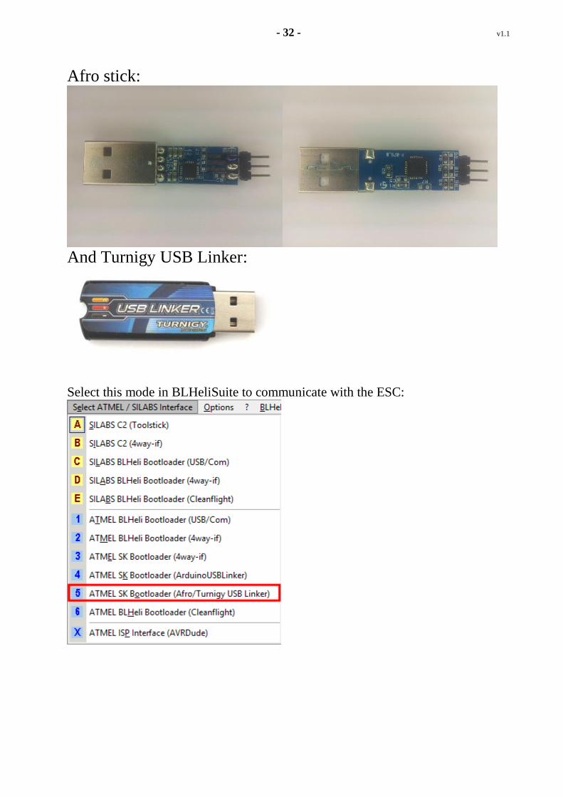
Afro stick:
And Turnigy USB Linker:
Select this mode in BLHeliSuite to communicate with the ESC:

- 33 - v1.1
Then select the COM port that is assigned to the stick:
Select “COMx [Silicon Labs CP210x USB to UART Bridge (COMx)]”
Note that COM7 shown here is just an example. The actual COM port assigned will vary.
Caution: Do NOT connect the middle Pin (V+) to ESC! This could toast the stick.
Power up the ESC (connect a battery) and click Connect.
Note that for BLHeli Atmel code revisions 13.1 and below, it is necessary to click
Connect, and then power up the ESC.