Embed Size (px)
Citation preview

Programming
Dav to.'..-
0 New Terminal Facilities Desinn ^ Te>

DAVID A. DOSE
THESIS -Spring '80
GREGG COUNTY AIRPORT TERMINAL
ARCH.^22 - PROGRAMMING
Dr. Lawrance Garvin
11/79

TABLE OF CONTENTS
SECTION ONE
Goals aJid Objectives 1
SECTION TWO
Background Study 5
Introduction 6 Urban Context 8 Air Service History 19 Existing Facilities 22
SECTION THREE
Site Analysis 29
Introduction 30 Noise 31 Site Summaries 35 Maps (38)
SECTION FOUR
Activity Analysis 39
Airport Operations ^0 Activity Statistics & Perdictions
3 Activity Studies -50
SECTION FIVE
Space Summary 6I
Passenger Process 62 Cargo 63 Administration Sk Other 6^
SECTION SIX
System Performance 65
Structural 66 Electrical 66 Acoustical 66 Lighting 6? Mechanical 6? Baggage Handling 69 Passenger Loading 70
SECTION SEVEN
Space Functional Relationships. . .71
Space Relation Diagrams. . . .7^ Case Studies 79
SECTION EIGHT
Detail Space Requirements 83
Passenger Process 84 Cargo 97 Admlnstration 98 Other 100
SECTION NINE
Cost Analysis 101
Finance Sc Ovmershlp 102 Value Engineering IO3 Cost Estimate 104 Cost Breakdown 10^• Revenues & Expenditures. . .105
SECTION TEN
Bibliography IO7
-II-

INDEX OF DRAWINGS
SECTION ONE
SECTION TWO
East Texas Map . , . . .:. 6 Regional Map 8 Population Projection Graph 9 Resoux-ce Map 12 Sketch of Existing Terminal (front).18 Existing Facilities Map (22) Sketch of Existing Terminal (back) .21 Sketch of Existing Tower 23 Sketch of Existing Fire & Rescue . .25 Sketch of Existing Terminal (side) .27
SECTION THREE
Sketch of Landowners House 31 Sketch of Nearby Vacant House. . . .32 Aircraft Noise 33 Existing Site Simmary. 35 Site 'A' Summary 36 Site 'B' Summary 37 Site *G» Summary 38 Areal Photo (38) .Baslol-Land Use Map Slope Map • • Vegetation & Noise Map . . . . . . Micro Climate (winter) Map . . . . Micro Climate (summer) Map . . . .
SECTION FOUR
Model Airports List » Airport Activity Statistics ^5
Peak Hour Charts ^7 Airport Load Graph 47 Sketch of Existing Terminal Lobby .49 Flow Charts (deplaning passengers).51 Flow Charts (arriving passengers
and baggage) .52 List of Amenities =53 Gross Section Diagrams 54 Flow Charts (cargo) 58
SECTION FIVE
List of Required Square Footage . .62
SECTION SIX
List of Structural Requirements . .66 Noise Levels 66 Lighting Requirements . . . . . . .67 Air Change Requirements 69 Baggage System Diagrams 68 Jet Way Diagram 70 Jet Way Requirements 70
SECTION SEVEN
Space Relation Diagrams 72 Airport Operations 73 Passenger (access interface) .74
(non'i.nterfpce) . . .75 (inteijface) 76
Cargo . .11 Adminstrative 78
Case Studies (Lubbock Regional) . .79 (DF/W - Braniff Int.).80 (DF/W - Continal). . .81
-III-

INDEX OF DRAWINGS (cont.)
SECTION EIGHT
Ticket Lobby Image Sketch 86 Baggage Claim Lobby Image Sketch . .88 Security Image Sketch 90 Interface Lobby Sketch 92 Departure Lounge Image Sketch. . . .94 Apron & Loading System Image Sketch.96
SECTION NINE
Cost BreaJcdown 104
SECTION TEI'J
Bibliography 107
SECTION ELEVEN
Aircraft Data Aircraft Dimension Existing Terminal Floor Plans
-IV-


GOALS AND OBJEGTTVE.q

GOAIJS & OBJECTIVES
For the community
With the mass influx of population
migrating from the northern states to the
"Sun Belt" area, counties such as Gregg
must accomodate this new population in order
to maintain their productivity and other
aminities associated with mass growth to
provide for a stable economic growth.
With adequate terminal facilities
Gregg County Airport will become more at
tractive to larger airlines. This will
create more convient flights for the pop
ulation, so they can avoid commuting
140 miles to the Dallas Fort Worth area
for convient airservices. Remodeling of
the existing facilities will serve as the
catalyst attracting more passengers and air-
carriers. Thus allowing the airlines to
create a more convient schedule of flights.
To further add convient services to
the county and with concern for energy
conservation, a mass transit system through
out the city of Longvlew could be consoldated
into the airport and other transportation modes.
Restoration of the Old
The period in which the old terminal build
ing was constructed, marks the point in time that
East Texas descovered its wealth and experenced
rapid growth. Buildings of this era are important
to the people of this area and must be preserved
as part of thier heritage.
Today modern airports architecturaly lack the
romance of the most ordinary train station. All
efforts muat be taken to utilized the existing
facilities until maximum capacity is reached, but
before this situation occures, considerations for
designing new terminal building is evident.
In Designing the New
The primary goal of designing new terminal
facilities is so that long range needs can be met.
The key factor to this expansion of the terminal
building, the parking lots, and the runways. By

establishing new facilities that are capable of
vast expansion. East Texas will be assured of
adequate service as it experiences enormous
growth in the future.
Ability for the new facilities to meet
accelerated load growth. Flexibility in the
spaces of the terminal building, parking lots,
and access roads, all are necessary for effect-
iviness.
To simplify circulation, separation of
passenger activity is required(i.e. processing,
cargo, and admimistrative activities), where-by
the departure lobby or interface is to be sep-
erated from the noninterface.
Strong considerations for energy conserv
ation and utilization of passive and active
solar energy as well as use of low maintanance
materials, will achieve a lower operating cost
for the county.
The use of amenities such as restuarant,
cocktail lounge, meeting rooms, and cargo
rental space will attract additional building
use and revenue from Longvlew and other county
communities.
The New and The Old
(Terminal design objectives for the convience
to passengers)
Minimize walking distance of passengers
between thier cars to the departure lounge.
This design will function in the since of
passenger convenience, and also aesthetically
pleasing to promote human interaction. The
proposed new design will retain architectural
heritage while providing a more functional atmo-
phere with the use of wash and down lighting;
carpet as opposed to tile; and plants and
banners to stimulate the eye of Interest.
For New and Old
(economical feasiblity to airlines)
To provoke County support and interest in

the proposed design it is suggested that all
project operation cost be justified and alter
native revenue incomes be mentioned. By
providing this analysis it is not only sub
stantiate the feasibility for the county but
will also enable the corporate airlines to
maintain an effecient cost per passenger quotient.
With the information obtained through
market research will enable the county
to achieve an operation capable of retaining
monetary effeciency not only during peak hours
but also during slower times of operation. This
will facilitate high earnings and provide the
county with a profitable Institute in the near
future, assuming the county is able to receive
the largest airport capacity per dollar invested.
-Zj..


BACKGROUND STUDY
1. Introduction
2. Urban Context a) Gregg County Region b) Population c) Future Population Projections d) Economic Base
Raw Materials and Natural Resources Manufacturing Retail Trade
e) Education
3. Air Service History
4. Existlna: Facilities a) General b) Airfield c) Fire & Rescue d) Hangers e) Other Constructions f) Terminal Building
-5-

The Sunbelt, which includes California,
New Mexico, Texas, and several other Southern
states has become a popular area of expansion
and economic growth In the United States.
Oklahoma
} \ Pat M.?ysG,
/('Kansas
Denison " "" 0
Lakp Bonham
•^Resprvoir
'Paris
I Red niver
Mount Plea' ianl , ,^ t n i o i (n/i? . "XCypfest
CJ* Afikp rnwnknni , { rprlng^ l-nkc / I / rA tn/in
"•-If J r SSs ^^ Winnsboro Hubbard^ l-f>l"' Owlman
^ ^ Luke Hanttin^ftinke^ - 1 2 0
Texarkana
Lalrg l Vrip Wl PKlW!>n MILES FROM LONGVIEW
Lukp O Cip Pines'^
.'<e-:r-'VTO^\pr,i(e';rr/i(>'^ Tyler
•—* ^::.:-; .•^VT' l^^rshailj • Tyler,Kilqore«ff^^e''*'p ^, 1 /
! i t ( • I • ' • (
Lo'Jisinna
Galveston
EAST TEXAS MAP
City
Beatimont Carlhaqe Caddo Lake Center Dallas Denison Fort Worth Galveston Henderson Houston .lacksonvlll'' Jasper Kilgore Livingston Liilkin Marshall Monnt Pleasant Narogdoclies P.iris Poll Arthur San Augustine Sherman .Shreveport Texarkana Tyler
Miles
200 36 46 63
121 160 155 259
30 209 53
140 12
133 90 23 69 66
118 217 82
152 62 98 37
This sudden popularity can be attributed to the
moderate climate and low cost of living, as well
as the easy access to natural resoTurces and the heal
thy economy. Longvlew, Texas has been caught up in
the Sunbelt and now boast the title of the third
largest industrial area in Texas. Ironically, the
jet age overlooked the small community in Gregg
County and failed to provide adequate commair ser
vice because it was uneconomical with Dallas
located only 120 miles to the West. Air service
proceeded the late 70's have been Metro Flights to
Dallas, Houston and other near by cities. There
is a frequent large passenger carrier which arrives
and departs when the need arrises. Large aircraft
have been replaced with a smaller craft due to the
deregulation of the airline. The demand for the
air service in Longvlew is now Increasing due partly
to the growing popularity of East Texas. Also con
tributing to this constantly growing need is the
economic side of mass air transportation, the energy
crisis, and population growth during the past decade.
-6-

Without adequate terminal facilities Gregg County
Airport may seem unatractive for future services,
to the larger air carrier services. Unless this need
for air services is met, Longvlew will not be able
to keep up with the industrial and economic growth
of the rest of the Sunbelt, and will find its future
expansion greatly hindered. Background studies of the
Airport and Gregg County are divided into three areas;
Urban Context, Existing Airport Facilities, and The
History of the Airport. The following chapters on
Urban context is a study which is the basis of a
future airport load.
-7-

LONGVIEW'S RELATION TO REGION
URBAN CONTEXK^ GREGG COUNTY REGION
Gregg County is situated in the Industrially
expanding triangle of Dallas, Houston, and Shreveport.
Three major highways serve the area: Interstate 20,
U.S. 80 and U.S. 259. Easy access in the County is
made possible by Loop 281 and major thoroughfares
run in and around the Longvlew area. Several railroads
serve the area and provide passenger service, while
Missouri-Pacific, Texas & Pacific, Atchinson, Topeka
& Santa Fe railroad companies move freight to and
from the County.
Longvlew, the largest city and the County seat
of Gregg accomodates over 60% of the Counties pop
ulation. The remaider of the East Texans are scattered
in nearby towns such as Gladwater, Kilgore, Liberty
City, Pinetree, and Sprlnghill. Airport facilities
will also serve several towns within a 50 mile radius
Including Tyler, Henderson, Carthage, Nacodoches,
and Marshall. This is illustrated on the East Texas
area map on the preceding page.
wnviN ^rptiNCO ANO ASSoriAtcs
-8-

POPULATION
The city of Longvlew, over the years,
has maintained a strong and consistant rate
of population growth. As a result of this
growth Gregg County has also experienced an
Increase in population each decade. The
following information Illustrates the population
growth of Longvlew and Gregg County from 1930
throu^ the current year.
flu 10,000
YEAR
1939 1940 1950 i960 1970 1979
LONGVIEW
5,036 13,758 24,502 40,050 46,744-
GREGG
\5,ll^ 58,027 61,258 69,436 75,929
CHANGE
31-9^-23.7% 40% 57.7% 23.6%
Historical Analysis
The first discovery of oil in East Texas
in October of 1930 drew people to Gregg County
and its nieghboring counties like a magnet in
the 1930-1940 decade. The strike in Rusk County
spread to Longvlew and Kilgore in 1931 and brought
a period of prosperity to the area. This period
marked the greatest era for East Texas until
its popularity in the 70's. Although the mag
nitude of the jobs created by the oil industry
did not stay constant, the discovery opened
up opportunities in other industrial fields in
Longvlew. During the 30's and 40's, approximately
20 manufacturing plants set up operations in
Longvlew. From this strong industrial base the
city has rapidly expanded to its present day
-9-

prosperity and to a great extent is responsible
for the continued growth and wealth of the
community.
Future Projections
The city of Longvlew has grown from a small
town of 1,525 people in 1880, to a city of 58,000
to 60,000 in 1979- A steady growth occured between
1880 and 1930. Since 1930, Longvlew has experienced
vigorous and solid growth both in population and in
industry, due to the ab\mdance of resources of the
East Texas area. It is predicted that this growth
will continue and that the population should double
from 1979 to 1990.
-10-

Economic Base
While the first two periods of Longvlew*s
development may be attributed first to agriculture
and secondly to petroleum, the current development
period should be recognized as that of industrial
and trade diversification and expending influence.
The geographic relationship of Longvlew to the
natxrral resources, the people and financial re
sources of the state provide an opportunity for
continued significant expansion of the economic
base and the Community's population.
Raw Materials and Natiural Resources
Gregg County and its progressive cities of
Longvlew, Kilgore,and Gladewater are in the geo
graphical center of an area also known as the Natural
Resoirrces Belt of East Texas.
Oil
The extensive petroleum development in this area
constitutes the greatest proven oil pool in the nation,
Due to the magnitude of this industry, it would be
repetitious and superfluous to delve into it
deeply in this testimony.
Steel
Steel plus oil, two of the products which
hold the highest places in the economic and
physical assets of the United States both in
peace time and war time are in abundance in this
area. Gregg County is in the center of 22 East
Texas counties which contain one of the largest
iron ore deposits remaining in the United States.
Such deposits axe now being exploited and pro
duced by the expanding Lone Star Steel Co. imm-
ediantly North of Gregg County. R.G. LeTourneau,
Inc. now operates a steel mill in Longvlew.
Natural Gas
Natural Gas plus oil plus steel in abundance
points up in the importance of this area to the
entire United States. Gregg County is the
origin and a source of supply for the famous "Big
Inch" pipeline which is now carrying 450,000,000
-11-

*€H3ensoN SUB. c^srfc ^c —
-«.««» *#a CO
S K f ^ n - * « W « ^ IMCH TOOL
AMBASfiAXXVi tOLLEOe
MONT* '0-55 Nf
9MK>P 5lCf " - -pe » H04T
STUOWO TOOL ftiuOiCa
uaus MFft ca
£*ST T l i A S STTU.'CASl1ft »K.
j ossoc / r / sAfinMs ca
RCLLT PLOW c a
I C N W r T TOOL CQ-
WLOOBt CERAMICS ^=--
LiTOUMCiU 9TCEL
UTOlMtCMI MFS. •<- I
«£SI5T0(. -i*r ca
j iCMONV»j.E :C3LUE«
- PiTnUN IMOUST0HIS — UWe » » * • ST IH .
'>C*<A«L ffTMUMCi
— KWTwwiSTMl iaJCTWC POHCA cO
— utv%. Mwoucrt * c
CHjMftU COU.ECr
- frEMCO • » " * CO
- • / — L O C W * * I U C H M rn
» « « « 0 n CAfl LWt 3(K * C ' • « -Mt
- ' E « * » €*STIUN CQ
__ ~^BAlLMO«ajEOIV - M I L U M H W t
:fjG "**•< '<tDN»NC€
• f^avFP^L MATCH
— wircO C»»e«»C><. CQ
JTOi-tTarf M K K
fM0SM«LL Mt'lCK
VUAASMU.t. r . f fS iwe.
bfcBCO CO.
pMiM STEEL otsTwfi ca
.MAnSHiLL CM> * X e L CASTMB
* U M W L M M C cdN#
— kA9T f t a * t •ft»Ti»T COLI.EV
iL/VAfAOSMCr tOM»
^ T H « « 9 r E n « e t . C C T M C » 0 «
•_ .CAm^*ct ojp ca
*5 , \ » ^ . . ' I • I . ^
COCA COLA •OTTLM* C a Jcowwewwt c«« en
isroM TOOL i •ucH ca
<iir«<m)-t«u " « OB M«v<MMio TAAK ca
UEwcLL -oboot« rouMrui
INC TOpCcQ
i\Cftfir t w CO
tuccWrt coat
IFDve VLW ft MCGULATOM Ca
iTHCM* tafl c a
SOUTHWCSrtllHKLL rcL£»H9
'AiTCD <U9 COW
'voirr xtMxS. CO
Oi^ j Sr^tT CQ
EAST Tt«AS OIL "ELO
NAfURAL ("lAS
RESOURCE MAP
-12-

cubic feet of gas daily to the East. One of
largest gas gathering centers in the world
adjoins Gregg County.
Timber
Gregg County is also located in the East Texas
Pine Belt which includes nearly all of the State's
saw timber and approximately 90% of all commercially
valuable tree growth.
Other Minerals
Lignite, clays and silica sands are abundant in
the area. There are several brick plants within a
thirty mile radius of Gregg County Airport.
Water
Fresh water in unlimited quantities is available.
Num-erous fresh water streams fed by about 44 Inches
of annual rainfall, the largest of which is the
Sabine River, provides huge volumes of fresh water
streams or from artificial lakes which can be constnict-
ed easily and cheaply. Lake Cherokee, a few miles
South of Longvlew, is an example.
In addition to rainfall there is an easily
accessible reserve of underground water.
Power
Southwestern Electric Go-operates is one
of the largest plants in Tesas, 180,000 kilo
watts, located near Longvlew on Lake Cherokee
and another North of Longvlew generating 40,000
kilowats.
-13-

Manufacturing
Manufacturing employment has accounted foi'
the largest gain of any in Longvlew in the past
20 years. In 1950,14.^ employed were in manu
facturing and In 1970 over 25% of Longvlew's
employees were involved in manufacturing. The
gain in durable goods manufactured represents more
than a threefold gain in 20 years and a similar
expansion occurred in the nondurable employment.
Few virban areas can boast so large a portion of
their portion of their employment involved in
manufacturing. In 1970, 18.6^ of the employed
persons in Texas were in manufacturing while in
Dallas Metropolitan Area 23.6^ of the employed
involved manufacturing. The high percentage
of manufactxrring employees in Longvlew is
considered to provide a strong supporting base
for other services relating employment. The
major manufacturers are listed and located on
the previous natural resources map.
Manufactviring
Durable Goods Nondurable Goods Sub-total
Nonmanufacturlng Wholesale & Retail Trade Transportation, Communications & Utilites Finance, Insurance. & Real Estate Service & Government Construction Agriculture & Mining
Industry Not Reported Sub- total
Resident-Employee Ratio
i960 Number of Employees
2,572 1.786
^J58^
5,771 , 1,796
971 6,753 1,898
2,366
^4,797 2.8
1
Percent of Total
1.04 7.2 17.6
23.3
7.3
3.9 27.2 7.7 9.5 3.5 100.0
Number 1970 of
Employees
4,15^ 2,640 6,79^
6,714
1,764
1,122 8,350 2,092
1,879
28,715
2.6
percent of Total
14.5 9.2 23.7
23.7
6.1
2.9 29.1 7-3 6.5
100.0
-14-

L\\^ *_f«»J.-l. XJ-GbV<L^>
As the City's geogaphic area expands more
of the County retail establishments will fall
within the city. It will be particularly
important to seek to retain the general
merchandise, apparel and accessory stores and
others in the downtown area of Longvlew as furture
shopping centers develop will tend to accelerate
the dispersal and create competitive conditions.
Retail Establishments
RETAIL SALE, I967
CITY OF LONGVIEW AND GREGG COUNTY City of Longvlew Gregg County
# of Establishments Sales (,iOOO) # of Establishments Sales Building Material, Hardware and Farm Equipment General Merchandise and Group Stores Food Stores Automotive Dealers Gas Stations Apparel and Accessory Stores Eating & Drinking Places Drug Stores Miscellaneous Re ta i l Stores Non-Store Re t a i l e r s
Total
26 29 84 63
100 42
101 18 101
6,881 1 5 , ^ 3 22,135
22,912 7,603 5.617 5,607 4,5^6 8,498 2.998
43 44 154 101 174
70 193 30 185 82
8,474 17,457 33,619
34,777 11,959
7,832 7,911 6,054
16,566 3,623
688 107,374 1,145 154,941
-15-

EDUCATION
Area Colleges
Kilgore Junior College Kilgore
Tyler Junior College Tyler
2 year co-educational
2 year co-educational
Stephen F. Austin Nacogdoches
East Texas State University Commerce
4 year co-educational
4 year co-educational
LeTourneau College Longvlew
East Texas Baptist College Marshall
Centenary College Shreveport, LA.
Ambassador College Big Sandy
Lon Morris College Jacksonville
4 year co-educational
4 year co-educational
4 year co-educational
4 year co-educational
4 year co-educational
-16-

Transportation is a vital factor in the
continuing growth of Gregg County. It has become
the largest and finest airport in East Texas due
to is expansion in the late 1960's. Longvlew
was automatically recognized as the key transpor
tation center in this area. Interstate 20 was
opened in April of I967 between Shreveport and
Dallas and the area was already served by U.S. 80
and thi'ee railroads. In the not too distant fu
ture Longvlew will have barge transportation on
the Sabine River. These are the elements that
make a big city bigger. Its what fed the indus
trial growth in the early days of the railroad.
Good transportation facilities attract industry.
Longvlew can boast of having the third largest
commercial runway facilities in Texas, its 10,000
foot length sTorpassed only by those at D-FW,
Houston, and Lubbock airports. These facilities
need to be utilized and the existing terminal
building should be brou^t up to date with air
trsinsportatlon technology. This inturn will
attract more airline services to satisfy the
communities needs and conveniance to the pass
engers. This action needs to be taken now while
the design of new terminal facilities across
the runways are in progress.
Sources
1. Texas Monthly, Longvlew Morning Journal
Dallas Morning News
2. Sprimger & Associates, Urban Planning
consultants, Dallas, Texas
3. U.S. Census
4 . R e t a i l Census, 196?
5. Longvlew Morning J o u r n a l , March 1, I967
Volume 35, No.50
- 1 7 -

v ^ - i " ~-
\
-18-

AIR SERVICE HISTORY
Upon completion in I957, the Civil Aeronaut-,
ics Board (GAB) awarded a certificate of public
convenience and necessity. Mid Continent Air
lines offered flints to Tulsa, Houston,
Muskogee, McAlester, and Dallas. Mid Continent
major competitor'Braniff•, supplied services to
Tulsa, Houston, Oklahoma City, Ft. Worth, Dallas
and Waco. In 1948, Delta Airlines began to offer
flights to Shreveport and Dallas. The GAB felt
that Delta should be allowed to fly to Austin,
Temple, San Antonio, Midland-Odessa, and Texarkana.
During this period of time aircrai't used were DG-3,
DC-4, DG-6, 1049G, and 340; capable of flights
up to 4500 miles. With a passenger capacity of
100 people these planes were short range and STOL
crafts. Gregg County Airport also had a good
strong air freight service.
In 1951 at the Central Renewal Proceedings
conducted by the CAB, Braniff Airways and Mid-
Continent Airlines merged and became Braniff Air-
lines. The decision of the case took Braniff com
pletely out of Gregg County Airport and was re
placed by Trans-Texas. Which survived such cities
as Dallas, Houston, Tulsa, Texarkana, Tyler, Beau
mont, and Shreveport. These points were also being
serve by Delta-G & S Airlines, which also was sus
pended in 1955. This loss of one plane and one
carrier was restored with flights offered to New
Orleans in 1959- The new aircrafts at these times
were the midrange crafts capable of a passenger
load of 120 people and a range of 4,000 miles
which are thej DG-7, DG-85O, and Boeing 707-120.
With the introduction of the jet-liners, the
DC 9&10, 707-120, 727-100, 707-320B, 737-100,
Gregg County Airport had been surpassedby technology.
It becajue uneconomical for a plane capabile of
trsinsporting I50 passengers 5,000 miles, to
service Longvlew, Unless there is an occupancy
rate of 60% for fligjits longer than 3OO miles
the jet-liners are not economical. Longvlew,
unable to generate this type of need, was un-
desircable to the larger Airline Companies.
-19-

The problem grew worse in the 70's, with the
Introduction of the wide bodied and sub-sonic
jets. Which one is the DC 10, with a passenger
load of 230 and a range of 4900 miles. The other
is Boeing's 7^7-320B capable of transporting
375 passengers, up to 9000 miles. The facili
ties at Gregg County Airport is capable of land
ing these airplanes, but the need for them has
not yet arrived.
Today air service is supplied to most
major cities in the southern region, by Trans-
Texas and American Airlines and several other
small companies. With the deregulation of Air-
travel in Fall of 79 the popularity of air travel
with its convenience and economical, the air
lines realize a market for the short range and
medium range aircraft services. Along with the
popularity of air travel, the growth of the
Gregg County region has developed a need for
convenient service and tearminal facilitier that
are capable of handling the load. With the
vast growth of the sunbelt region, predicted
by the turn of the century, East Texas will require
adaquate transportation services. Transportation
services facilities that can deal with short range,
medium range, and large capacity aircrafts.
-20-

•• -4
-dj.-

EXISTING FACILITIES
General
Gregg County, indicated in orange is
located 8 miles South of Longvlew on Airport
Road just off of State Highway 149. The
area has an abundance of water, found just
between the airport and the South Industrial
District is the Sabine River. The river at
one time was used by barges on their way to the
Gulf of Mexco.
The river hasn't been used for transportation
for some time but has good potential for future
use. Antother source of water near the airport
is Cherokee Lake, located off of the Southeast
runway. The majority of the shoreline is a
zoned residential area with the exception of
the Southwestern Electric Power Company
plant on the North shore. The entire area is
RUNWAY DATA
E f f e c t i v e G r a d i e n t
% Wind Coverage
Insrument R/W
Pavement S t r e n g t h
Approach Surface
Runway L i f t i n g
Runway Marking
Naviga t ion Aids
R/W Lengths & Widths
13-31 0.087
93.7 Yes 320,000-TT 153,000-D 508 1
HIRL
a l l weather
ALS-ILS
10,000 X 150
17-39 0.24
94.9 No
45,000
50:1
MIRL
ins t rumen t
None
6109 X 150
4-22
0.33 92.6
No
25,000-D
40 :1
MIRL
b a s i c
None
5205 X 150
-22-

KJ ^L-~. .yW
•-^^Al>.^!^-^^^
-23-

covered by dense forests and heavy foliage,
indicated by the green, as well as open
pastTires indicated by the lifter shades.
The South Industrial District is the
largest of the three industrial sites and con
tains several of the largest companies and cor
porations. These include; Texas Eastman Co.,
Screw and Bolt Corp. of America, Trailmoblle
Division, Pullman Inc., and the Letourneau Steel
Mill and Manufacturing Co. The entire area is a
future prospect for housing and industrial growth.
Airfield
The existing airport site has great poten
tial for future air transportation service to the
East Texas area. The air field consists of 3 run
ways and 13 taxi-ways, all of which are well lit.
Eight of the 12 structures are located around the
apron which is located on the West side of the
airfield. The remaining buildings are to the South,
except for LTV which is found on the North side of
the site.
Air Traffic Control Tower
The (ATCT) is located 2,000 yards South of
the runway intersections. The towers maintain
contact with aircraft in the Immediate area of
the airport, and a radius of 150 miles. As of
1979 activity consisted mostly of general avia
tion, second was Airtaxi, third was Air Carrier,
and fourth was Military.
Fire suid Rescue
Constructed at the same time as the new
control tower in 1975, was the Security and Fire
Rescue located south of the Air Terminal. The
Fire station and seciArity located in the facil
ity is on 24 hour call and has all of the nece
ssary equipment to handle most any emergency
situation. In service is three modern heavy
pieces of fire fighting equipment.
Hangers
When approaching the airport from Longvlew,
the first building sighted is the Piper Hanger
w h i c h i s n o t t h e o n l y ^^tvnp•t11-rft I n n a t e d ar l ja r i f^pt
-24-

-25-

t o the a i r f i e l d . The Piper hanger i s the l a rges t
of the 6 hangers on the f i e l d and i s the regional
s a l e s headquarters for East Texas. The new and
second l a r g e s t hanger i s located near the West
end of the runway 35. Gregg Aviation, ju s t
south of the F i re and Secur i ty Rescue Building, i s
the t h i r d l a r g e s t hanger. The majority of t h e i r
a c t i v i t y i s a i r f r e i ^ t . Located next to Gregg
Aviation i s R. Lacy I n c . , and Eastex Aviation.
Both of these f a c i l i t i e s run chartered commuter
se rv ices to Dal las , Houston, and Shreveport. In
add i t i cn they a lso are involved in f l i ^ t t r a i n i n g .
The l a s t of the bui ld ings of t h i s type, G.A.P., i s
located a t the East s ide of runway 35, near the
threshold .
Other Constructions
The remaining types of bui ld ings on the s i t e a re :
Texas I n t e r n a t i o a l Reservation Computer Center, and
LTV's mul t i -mi l l ion do l l a r f a c i l i t y . T I ' s Reser
vation center i s located South of the terminal parking.
I t was constructed in 1975 and handles a l l r e s
ervat ions for TI. The computer center i s l o
cated West of the Fire Reserve adjacent to the
Terminal Building. LTV (Llng-Temco-Vought Inc . )
was constructed in the l a t e 6 0 ' s . At tha t time
i t was engaged primarely in design, development,
and production of a i r c r a f t s , m i s s i l e s , space man-
uevering systems, ground veh ic le s , and manage
ment of range and launch operat ions and engin
eering support se rv ices .
Teminal
The ex i s t ing a i r t e rmlna l was constructed in
1946 and opened in 1947 for se rv ice . I t s a two-
s tory free standing l i nea r bui ld ing where the pass
engers must walk out to the waiting planes on the
aprons. Three major function zones are well de
fined within the terminal . Ground leve l serves
a l l of the passengers needs; t i c k e t s a l e s , baggage
claims, lounge, cafe , a i rpo r t management, and car
r e n t a l , as well as a i r f r e l ^ t and the o f f ice .
-26-

-27-

The offices for the airlines and the Federal Ad
ministration are found on the second floor. An
observation deck was located at the roof level
of the second floor. Since the opening exterior
stairs have been removed and access was closed from
the tower. The original control tower is the domin
ating featxjre of the 33 year old building. The
building has its own architectxjral character that
marks the start of a new era for East Texas. Pre
servation and rejuvlnation as well as adaption are
essential guidelines for any future development of
the building.
-28-


SITE ANALYSIS
1. Introduction
2. Maps
a)
b)
c)
d)
e)
Basic Land-Use
Slopes
Vegetation and Noise
Noise Study
Micro-Climate Winter Summer
Site Analysis
a)
b)
c)
d)
Existing
Site A
Site B
Site G
( 3. Site Analysis <
-29

SITE ANALYSIS
Site analysis of the Gregg County has been
done by the use of five basic maps; Land use. Slope,
Vegetation and Noise, Micro climate for Jan. 21, and
Micro climate for June 21. The land use map describes
three major features of the site: the basic
land use, views onto, form, and within the site,
and site drainage. The slope gives a 3 dimen
sional study of the site land features. Moderate
and slight slopes as well as the direction of
drainage is shown by the intensity of the lines.
Plateaus are indicated by the white areas and the
valleys by the solid gray areas. The Vegetation
and Noise Map shows tree coverage and open fields
on the site as well as the noise generated areas.
Also Illustrated are the bodies of water. Micro
climate maps are the most complex and show the
slope thermal conditions, air movement and pre
vailing winds, as well as the climatic data needed
for future design. The selection of the site will
be influenced by the following factors:
1. Type of development of the surrounding
areas
2. Acceslbillty to ground transportation
3. Availability of land for expansion
4. Surrounding obstructions
5. Economics of construction
6. Availability of utilities
There are three large tracks of land that have
been selected for further development. Closer
views of the three sites are provided for further
detailed site analysis. Each site can be refered
to the basic land use map for relationships to
each other.
-30-

NOISE
Besides the very important problem of noise
created by overflying aircrafts, there are other
noise problems created within the airport and
the adjacent communities due to aircraft ground
operations and other maneuvers prior to take-off
and ai-ter touch-down. Noise due to aircraft man
euvers is catagorized into two groups; the first
is caused by ground movements and operations,
the second is during the Initial stages of the
take-off or the final stages of the approach
and landing procedures.
Noise created by ground operations of the
aircraft is broken down into three sources;
taxiing and holding noise, engine ground run
ups, and auxiliary power unit operations. An
aircraft leaving or returning to the air ter
minal passes near the terminal or airport per
imeter with dwellings not to far away. At other
times aircrafts may have to be put on hold were
the engines operate at a low power setting.
-31-

c \
/
A
•> \*^;^u
•— —
•32-

So continuous flow of ground traffic then could
have effect on noise on adjacent to the site.
Engine ground rim-ups received early recognition
around air bases, it has also produced similar
situations at commercial airports. The engine run-ups
ocGure in a variety of situations either after an en
gine is overhauled it must be tested, or as part of a
repair or maintanance situation of the total air-
-c continuously as the en--33-
glne thrust settings are changed. Auxiliary
power unit operation is required either at passenger
embarking or loading or during cargo handling pro-
ceedures. Not only can the ground crew be affected,
but also passengers can be too in a acoustically
untreated building.
Ground noise created on the site must care
fully be delt with on and near the site. Across
is an illustration of the typical ground noise cont •
ures from AUP operations.
Noise generated by airport operations can ex
tend miles from the site, this intensity of noise
occures on take-offs and landings. The loss of
gr-ound effect takes a tremendous amount of thrust,
and is essentially an increase in noise levels that
occur as the airplane leaves the runway and the
excess attenuation of the ground falls away. As
an aircraft starts its glide path there is an
audible thrust change and is a significant factor
In the calculation of noise exposure. A more
important problem occurs just before landing
but principally occurring after touchdown, is

the noise produced through the thrust reverse
application. This sudden burst of noise of high
intensity but short duration is caused by the
sudden reversal of the exhaust gas flows.
The noise problems produced by the airport
can cause severe disturbances to those farm houses
and laJce houses in the vicinity of the airport, as
well as hearing hazards to ground staff. Besides
the obvious solution of source noise reduction,
the usual methods of control are the use of
barriers to obstruct the paths of noise pro
pagation and soTind-proofing of structures to
protect the occupants.
SOURCES
1. Landscaping for energy conservation
2. Time saver standards
3. FAA- Sound levels, resulting from aircraft operations
4. Planning & Design of airports
5. The Challenging Future
-34-

EXISTING SITE ANALYSIS
SUMMARY
ADVANTAGES
*Gost and maximum use of existing facilities
^Small Expansion
•Preservation and Adaption
*Small craft operation
*View of entire field
*Off-site drainage
*Flat and moderate slope
*Some vegetation coverage
•Good east sun exposure
•Good west sun exposure
•Good expansion in future
•Vehicular access
Further Existing Site Study:
DISADVANTAGES
•Piper hanger limits expansion
•Limited potential parking area
•Inter mixing airport traffic
-35-

SITE A - 63 ACRES
SUMMARY
ADVANTAGES
•Pleasant views on and off site
•Good access
•Good land topography
•Good access to runways
•Some tree coverage
•Good view of entire field
•Good North protection
DISADVANTAGES
•Smallest site
•LTV structure located on site
•Drainage through site
•Cold air pocket
•Limits new runway construction
Further Site A Study:
-36-

SITE B - 80 ACRES
SUMMARY
ADVANTAGES
•Drainage off site
•Variety of views
•Easy access
•Hi^ plateau
•Heavy tree coverage
•Good morning svin
•Noise protection
•North wind protection
•Good new runway expansion
DISADVANTAGES
•Valley throu^ site
•North slopes
•Screen views
•Limited air movement
•Evident destruction of trees
•Poor access to all runways
Further Site B Study
-.37-

SITE G — 143 ACRES
SUMMARY
ADVANTAGES
•Pleasant views
•Off—site drainage
•Best access to all runways
•Some trees on site
•Winter warm pocket
•Good vehicular access
•Good flexibility in new runway expansions
DISADVANTAGES
•Access valley throu^ site
•Cold air movement down valley
•North exposure
Further Site G Study:
-38-


S-^Jv^lV^ -S^^v

ACTIVITY ANALYSIS
1. Airport Operations
2. Airport Activity Statistics and Predictions
a) Demand Model
b) Alrtraffic Predictions Ji
c) Peak Hours ^
3. Activity Study ]] I'
a) Terminal '
b) Cargo
c) Building Construction
d) Utilities
e) Site Planning
-39-

AIRPORT OPERATIONS
An airport, like a modern city is devoted to
dynajnic movement. Its structured by a complex
system that facilitated passenger and cargo move
ment, maintalnance, aircraft control, and other
systems that provide for auxiliary support func
tions.
First, all of the movements and functions of
the passengers, cargo, and the airline employees
to and from the air-port are regulated by the
airport's timetable of the airlines and the
flights chosen by the passengers. Therefore
this timetable method is selected to describe
the airport operations. Passenger volume and
peak hour traffic have been determined by using
a demand model to a reasonable accuracy in a later
chapter.
Airlines are to take special care to corr
elate cargo movements to and from the community.
This movement is based on the county itself and
amount of its normal woking hours. This working
schedule is /renerally in conflict with the flight
schedule of the airlines. Also based upon this
schedule are working hours of the employees.
Therefore all major elements of movement to and from
the airport are worked around the preestablished
timetable on a programmed basis. This technology
can overnight change the preestablished schedule,
thereby changing all relationships and movement
to and from the airport. This occurs in three ways;
1. The aircraft manufactured have demostrated its
ability to produce new aircrafts with greater speed,
capable of carrying a gross load comparable to
that of existing aircraft. With these faster air
crafts, time zones that had one relationship now
have another. This affects the schedule and all
of the related disciplines. With the introduction
of Boeing l^f^ in March of I982 and the 767 in June
of 198/f, many airports will have problems with
-40-

adequate apron space. Because the wlngspan of
the two new jet liners are 25 feet longer than
most gates are designed for. This creates the
problem of aircrafts not being able to power out
away from loading gates on their own.
2. The ability to change and increase the pay-
load of the aircraft for both passengers and
cargo creates a new condition. This requires a
revision of function and all disciplines in
order to accept greater nvimbers of passengers and
increased cargo movement within a short period
of time. It also creates voids during other per
iods of the day.
3. This condition results fran both increased
payload and Increased speed. This will totally
change the predetermined schedule. Therefore, a
constant program factor in the development and
design of all functions and disciplines is the
fact that flexibility for future growth and
expansion must be incorporated.
Schedules established by the airlines must
be reasonably sound, for smooth operations. Under
the deregulation law of 78, any permanet change
requires 60 day notice. Because of the factors
that are dealt with it is essential that the depar
ture schedule may sometimes not be kept due to ad
verse weather conditions, mechanical difficulties,
and to the special considerations that arise l om
time to time. Even though an airline may usually
run on schedule, a 10 or 15 percent deviation
can raise havoc at the airport. Obviously no
two airports function in the same manner, there
fore an overload factor was evaluated. At the
same time efficiency on a 24 hour schedule is
high on the list of consideration of priorities
because peak hour operation may only be reached
two or four hours daily. Restraints have been
exercised to carefully control the amount of
-41-
structure that is designed to provide an econ
omically correct solution.
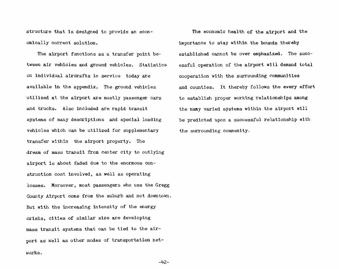
The airport functions as a trcinsfer point be
tween air vehicles and ground vehicles. Statistics
on Individual aircrafts in service today axe
available in the appendix. The ground vehicles
utilized at the airport are mostly passenger cars
and trucks. Also included are rapid transit
systems of many descriptions and special loading
vehicles which can be utilized for supplementary
transfer within the airport property. The
dreaJii of mass transit from center city to outlying
airport is about faded due to the enormous con
struction cost Involved, as well as operating
losses. Moreover, most passengers who use the Gregg
Goiinty Airport come from the suburb and not downtown.
But with the increasing intensity of the energy
crisis, cities of similar size are developing
mass transit systems that can be tied to the air
port as well as other modes of transportation net
works .
The economic health of the airport and the
importance to stay within the bounds thereby
established cannot be over emphasized. The succ
essful operation of the airport will demand total
cooperation with the surrounding communities
and coimties. It thereby follows the every effort
to establish proper working relationships among
the many varied systems within the airport will
be predicted upon a successful relationship with
the surrounding community.
-42-

AIRPORT ACTIVITY STATISTICS AND PREDICTIONS
By the use of a demand model, air traffic and
passenger loads have been determined with reasonable
accuracy on a short and Intermediate range. Vari
ables in the method were social, technological,
and economics, as well as travel demands. The
forecasts were also make on a long range basis.
This demand model on a 20 year forecast is very
approximate and places a strong emphasis on the
flexiblility needed in the terminal design. De
mand model forecast method was broken down into
five steps.
First: the observation of past and current
trends of airtravel demand. Not only for Gregg
County but other airports and communities that
have experienced similar growth patterns. For
review, see urban study in the introduction.
Second: inventory of the vai'iations as well
as similarities in the economic, social and tech
nological factors.
Economic Trade
General Bulsness
Education
Population
Flight Requirements
These economic factors narrow down the airports
which should have the types of airport loads and
fli^t requirements similar to Gregg County in the
future. The population of the model determined
the magnitude of the load expected for Gregg
County facilities.
-43-

MODEL AIRPORTS
1985 - Texarkana. Tx. - overall
others: Abilene, Tx. - Education, economic trade,
f l l ^ t requirements
Port Auther, Tx. - trade, economics.
Fort Smith, La. - trade.
Monroe, La.- general flights, education, economics.
1990 - Dallas, Tx, (love field) - economics, buisiness, key flights within Texas and
southwest region, education
others: Baton Rouge, La. - economics,
Jackson, Miss, - flight volume and schedules
Montgomery, Ab. - general flight schedules
2000 - Lubbock, Tx. (international) - flight schedules, flight volume, education,
economic growth.
Midland-Odessa, Tx. - trade, economics, education,
general flight scheduling, volume.
Lincoln, Neb. - volume, education
Shreveport, La. - trade, flights.
Little Rock, Ark. - volume, economics, education.
-44-

Third: Relationships based on the economic
factors were established to determine which
airports would serve as a primary study model.
Fourth: Projections for Gregg County were thus
determined by closely comparing the airports to
airports on a 5, 10, and 20 year range, (see table)
Fifth: Through a closer study of the airport
flights and schedules, the economic factors that
determined the schedule, and peak loads. Through
this model study, peak loads were reasonably
predicted for Gregg County, (see peak load graphs)
A ERPORT ACTIVITY STATISTICS - TRAFFIC FORGAST YEAR
1 75 Total Daily Avg. Weekly Avg. Monthly Avg. 1 Peak Date Peak Day Dly. Peak Op. 1980 Daily Avg. Weekly Avg. Monthly Avg. Peak Day
1985 Total Daily Avg. Weekly Avg. Monthly Avg. Peak Day
1990 Total Dally Avg. Weekly Avg. Monthly Avg. Peak Day
Carrier
2056 5 39 171 3/6 Tues. 10 124 .3 2 10 ThTor.
3608 8 61 291 Tue.
9850 24 171 821 Tue.
ITIlvlERANT OPERATION Taxi G
8198 22 157 683 7/23 Fri. 39 10831 30 206 900 Thur.
13449
36 257 1118 Fri,
9850 24 171 821 Fri.
eneral
45250 123 869 3770 9/22 Wed. 43 42288 115 812 3524 Sun.
34884
95 671 2907 Sat.
29376 80 565 2448 Sat.
Milt.
1034 2 20 86 11/12 Fri. 4 1968 6 3^ 164 Fri.
Peak
Tues. Nov, Dec.
Thur, Apl. Oct.
LOCAL General
48726 133 941 4060 10/2
354
OPERATION Milt.
1928 5 36 160 5/15
144
TOTAL
107192 292 2064 8932
567
290 2002 8736
51941 279 1977 8648
49076 256 1768 7975
-'O-

AIRPORT ACTIVITIES STATISTICS - TRAFFIC FORECAST CONT.
Year 2000 Total Daily Avg. Weekly Avg. Monthly Avg.
ITINERANT OPERATION Carrier Taxi G eneral 17524 4420 22032 48 12 60 337 85 423 17568 3110 I836
LOCAL OPERATION
AJRTRAFFIC PREDICTIONS
The volume of air carriers flying into
Gregg GoTonty Increases due to the demand and con
venience requirements of the community. The
increases of the air carrier lessons the need
for air taxi services between Longvlew and other
major cities in the southwest. As shown in the
Air Traffic Prediction Graph is a general trend
in airport growth for several reasons. Tur
bulence by the large jet liners require a 4
minute delay before a small class A air
craft may take-off. Turbulence is not the only
reason. Jet liners require a long approach and
departure. Small crafts can easily be over
taken by the larger planes. Alternatives for
TOTAL
^3976 240 1690 Gl^Z
general aviation lies in Longvlew's other air
field which handles small crafts only.
Peak Conditions are broken down into hours,
days, and months. The hourly scale is illustrated
by the use of the graphs. The graphs show peak
hour experienced in the late morning. These are
based on departures and arrivals, because of
this it must be kept in mind tliat the 6:00 clock
to 7J00 clock a.m. loads are generally departures.
While the 8:00 clock to midnigVit loads are arrivals.
This information determines the volume of space
needed for arrival and departure lobbies. Non
interference peak was determined by Friday and
Saturday due to overlapping of generally busi-
-46-

ma CAHBIKil AHS TAXI FEAI HOURS
600
(Wo.of 500
400 -
300 -
i!00
100
0 _
tyss
6 7 8 9 10 U U 1 2 3 <» i 6 7 8 9 10 11 12 (tb>e of day)
600
(Ho.of 500 Pass . )
IfOO
300
200
too
0
800
700
600 (Ho.of ;oo Pass . )
1*00 -
JOO -
200
100
0
1990
6 7 8 9 iO U U 1 2 3 •» 5 ^ 7 8 9 10 11 12 ( t u « of lay)
6 7 8 9 10 a 12 1 ,2 3 •» 5 ,6 7 8 9 10 11 12 ' ( i u » at day)
800 -
Aia Tmrnc PEBDICTIOW3
• . , 812
700
6oo
- . 6 7 .
• Ganscal Airlattoo
500
m
It
300
'•65
'•23
...,<£ Air Taxi
-ooooooo-^ „o<"> 257 °Oo
o* 206
ooo* _ 157
171 "•> •*171
100
t* Air Carrlar
°«ooooooo 85
1975 1980 1985 1990 1995
rCAB

ness men and travelers experienced on these days.
The peak month can be expected in the last quarter
of the year.
-48-

49-

TERMINAL
Flexibility is the key consideration for design
in respects to parking lots, public transportation
systems, curb frontage, baggage claim areas, check-
in areas, gates lounges and aircraft positions.
All of these elements and the airline operations
must be independently capable of growth. In
dependence and flexiblility are required to meet
the rapid change of aircraft technology and its
essential that the terminal adapt quickly to these
changes.
Parellminary Design conciderations is to be
based around two factors; the convenience to pass
engers and efficiency of operations for the airlines.
The existing facilities are a single level type
system with all processing of passengers and bag
gage occurs at the level of the apron level (See
Cross section diagrams). Seperation of arriving'
and departing passengers flow is achieved hori
zontally. In order to completely understand the
movement of passengers and baggage throu^out the
terminal facilities. Flow charts identifying
each stage of movement have been supplied. The
charts are not intended to represent space rela
tionships, only the process in which the passengers
baggage must go through when they are departing
and arriving. (Diagrams have been obtained from
Time Savers Standards)
-50-

PEFIANTNa IHTIBHATIOMAL
rAr.SEnc.ER
T~T ALIFH I
PUBLIC HEALTH b l P U R L I C I
I IMHInnATtON PASSPORT roHTHul, n
OAUGAOE CLAIM
I I US I I cusrms I
HEI(T-A-CAB 1 EHl [ IHtORHATION
1
MENTAL PIC. -UP
i ^^
( PR rvATE I f VEIItCLF I I
I T R A N S F E R I TO DOMESTIC I
PlIRLIC THAN.SPORTATIOtl I CONTINUE PER ENPLARINO
I . 1 PASSENGER n.OW
I ^E.^TINATlON DECISrON
I AIRPORT I EX fT I
DEPLANING PASSENGEItS ( i n t e r n a t i o n a l )
~ : ? i -
I DEPLANINa I I PASSKKOERS I
I
E§S I fiBEETEHS I J TEHMINATIKol I TRANSFKH I
I »^I PASSEMOER I I rNFORHATION I
I iHTFAiiME I I i r r i E R i i n r I TRANSFER I I TRAH-SFFR I
£ RENTAL
PICK-UP
CONTINUE lER LHFIANFNO PASSENGER FlOW
VALET z±
"CK-UP ] I Zfl'^... I |rRA»s';"c';,VA^T.O,f»| '^^l^^' |
' l ic t f 0E.S1 IHATIOH I nECrBION I ziz
I A I R P O R T I
^
DEPLANING PASSENGERS (National)

i P B O r i E AT I HOME OR I
I saiEiiuiE i ^ r MOTIVATION ^ ^ ^ ^
UEPAJITIJIIE •I'O AIHPONI-
I ROUTE
D E C m r o N
ATRFORT ENTRANCE
I AFRITNE
DECISION
I
10 FARKINO M I BAO
GUNB CHECK
I l l ' N , TERM I I SHORT TERM I
FAHKIHU I I PAHKrNO I
HWAI LT PARKING CURB
FiiiiEiFV-H --'"- H-'• 1- '
i f IT
21 I INTLKNATIOKAL : • LOUN'^E :
i t I U A T E I LllGNOt. I
I IHTRALIHE I I ENTRY TO I I I N T E B I I N E I
TRAM3FEH I I RUI IK ING J | TRANSKEil |
I —' i I PLIGHT I I iicTrT
[NF0Rt4AT10N I I COIMII'tH
AflRIVING PASSENGERS
S2;5Z:SZ^S: ( IHTHALINE I INTLJII fNE HAiiiAcJE I IIAGC.AUE
I ' ' ! I n CUBI>
HAG CHECK
i
CuUNTbll RAG CHROK [ OAIK
MAG l . l l t O
i h..{;,\.:f: LJ\ A G I N < ;
I.Ht.Hr- fEHU 1 ORG ILKM IIOLG
i r ^ r ^
II IANM Kll TO AlHi:ilAI r
n V2 I A l l l iHAFl '
HA(!I;A<;II; SYSTEM
-52-

Amenities and administrative functions take
place on the second level, but without switch
ing to the undesireable shuttle bus operation.
The operation has been quite economical and
suitable because of the low passenger volumes
in the past. As shown in the Gross section
diagrams, the remodeled new facilities should
convert into the two level passenger terminal
system. This will allow direct loading of
passengers and seperation of passengers and
cargo. In both accounts the placement of air
crafts on the apron are to be power-out type
positions. In the two level system jetways are
to be used for loading passengers while the
plane is on the apron. Directly related with
the loading technique is the concept and funct
ion of the gate lounges. In this area the open
dynamic and static concepts are to be used.
The basic function requirements are ticket count
er with all its communication equipment.
semisecure seating capacity to handle the pass
engers, flight identification, last-minute bag
gage drop, and circulation pattern which seperates
the deplaning passengers from the boarding
passengers. The depairture gate is the major
function of the interface lobby; while ticket
sales, baggage check, and baggage claim are the
functions of the non-interfaced lobby. (For a more
indepth study, see Detail Space Requirements)
Other general considerations for the con
venience of the passengers include: automated
doors, extra wide escalators, and moving walk
ways. Use of bilingual messages throughout the
airport are required for passenger guidance.
This terminal must also provide ajnenities
for the traveling public. These are to include
all of the following listed, each item has been
determined by the passenger volume:
Gar Rental Agencies* Cocktail Lounge Duty Free Shop Employee Snack Bar & Cafeteria* Gift Shop Hotel Information
-53-

ONE LEVEL CURB i-TOHINT
PASSKNCtinS
. BA(>;AGE APROH
ONE AlTD ONE LEVEL
I'ASSFJNGBHS DULY
UARIX)
ONLY
ARRIVTNr, >
\ ^ - -\
t — CARGO
- - UlECK
CUIM _ _ _ ^ APRON
ONE AND ONEHALF LEVELS
OURB FKOHT
-ARRIVING
£ nEPARTlNG
BAGGAGE APRON
TWO LEVELS
AfiRIVlUJ
ONLY
DEPARTING
ARRIVING
- \
_ ^ ^ - CLAIh r III!:PAR'I1NG
GIIB;GK - > APRON
CROSS SECTION DIAGRAMS
-54-

Insurance Vending* Parcel Lockers* Obseration Deck Newstand* Restuarant* Showers/Dressing Rooms For Grew Telegraph* Telephone* Valet
Restroom Facilities*
* Considered essential by airline operators
In addition to the amenities, medical and
First-Aid facilities should be included in the pass
enger terminal if they are not provided elsewhere
in the airport.
Public Information systems should be designed
in as well as the prime airline information
system that the airline user feels they can afford.
Some consideration needs to be devoted to the net
effect of space demands in presenting accurate up
date information to the traveling public.
For the remodeled existing facilities the move
ment system of passengers and baggage is the same.
These movements pattern are illustrated for
arriving passengers, deplaning national passenger.
deplaning international passengers, and baggage.
The architectural spaces are to perform the move
ment of passengers, employees and cargo are further
described, and relationships of these spaces are
demonstrated in following chapters.
-55-

CARGO
As the aircargo industry grows, the complex
on the airport designed to handle aircargo is
a significant element in the airport planning
and design. The facilities must provide for the
effecient transfer of air cargo between surface
transportation and aircraft. Four cargo centers
should be located so that an affective transfer
of cargo between air and surface is achievable.
Four primary considerations dictated the
site considerations for the cargo complex.
1. Taxi distance from most used runways
should be as short as possible, and yet smoothly
incorporated with the passenger operations.
2. Cargo facilities are to be readily
accessible by surface vehicles from the passenger
aircraft loading positions for efficient servicing
of aircraft carrying both passengers and cargo.
3, All four cargo areas are to be readily
from all access roads to the airport to assure
non-interference of vehicular traffic with air
craft movement areas.
4. Adequate space is to be allowed for
expansion of air cargo operations without en
croaching on other airport functions, particularly
without interfering with the expansion of the
passenger process.
These four primary considerations indicate
the general relationships with other functions
and activities. For the cargo facility to func
tion properly, design considerations are to
take into account the following: aircraft park
ing aprons, and requirements for aircraft parking
and loading. Roads on and off of the site as
well within the site should have convenient access
from the, passenger tex^minal. Tx'uck parking and
manuevering areas must also be provided. Park
ing areas for customers and visitors are required
-56-

with direct access to the receptionist. Employee
parking must also be considered but no direct
access is needed.
The air carrier cargo area is required to be
planned for multiple occupancy. There are four
major functional elements to be considered in
the air carrier cargo area. These are the freight
handling areas, administration area, personnel and
customer accommodations and service facilities.
The first and most evident function is freight
handling, there must also be truck dock positions,
facilities for airport to airport customers
who use other than trucks, and the delivery and
pick up of small shipments.
Recieving, sorting, weighing, lableing,
and building up of loads for shipment are the
major activities in the processing of freight
from the truck to the aircraft. There are a
number of factors which had a profound effect
on total space requirements.
1. Cargo turnover was affected by such
variables as types of aircraft, frequency of
service, time of day of arrivals, and departures
Inbound, outbound, and directional preponder
ance of cargo.
2. Density of cargo accounts for con
siderable conciderable amount of space. A ton of
cut flowers occupies many times more space
than a ton of machine parts.
3. Character of cargo creates a need for
specific space allocations. Refrigerated
storage is required for perishable cargo, and
other temperature controlled areas and needed
for live cargo. Bonded storage is needed
for customs, import/export control, as well as
security accomodations for valuable cargo.
4. Methods of handling and storage cause
variations in space requirements. Operations
utilizing forklifts and pallets require more
square footage for circulation and manuever
ing.
-51-

I fkR rHUrrnil J SCUBIUI£I I ^
y
I -FFoU IC AIRIIUE
. , FRmaiT ^ FOIUIaHDBiS
I
CAB 00 cou.ecTiu« PEA AlkLTIE
£ ATRPOHT
I/tSTINATIOH DlICI;iIuji
i lHTHALIMB I I CARQO I I
I AIWOHT L I PER PRIHTU.I POST DEPOT r ' I SOiEDULti I
SPECIFIC LOCATION
I I iirrciu.iNE I I I CARGO I
I - I . CARGO
CHECK-TH
I B i n . OF LADINO DOCUMENTATION
CLEARANCE
I SHORT-TERM I STORAGE I
I FA::SENG£R I KLIUHT GATE I
I LONG TERM I I STORAQK I
I CARGO I n-IOIIT GATE I
CARGO KLTUHI
I ^ I I I I HAIL TRUCK I 1 »
:SZ ^ ;S, I FLIGHT I
AIRPOHT poaT
FACILITIES
I
iJlyrhlBUTION
1 ^ ( T R A N S F E R I
TO AIRLINE I TRANSFER
TO AIRLINE
TT
I CAHGU 1
Fl lOlIT r.ATE I
1 I SOHT I I Or^fHiWJTE I
I I TO UITr I
I PA^DtiNdEH I I KI.IGMT G A T E !
^ ^
CARGO CARGO
-58-

In order to have proper cargo operation
adequate administatlve space is necessary. This
can be broken down into the reception area, sales
offices, management and general office space,
and communications centers, as well as centers
for efficient movement of freight, and the air
craft space control office. In order to pro
vide for efficient operation, equipment must
be kept in good working order at all times
maintalnance and storage of materials handling
equipment, such as containers should not be
overlooked. The functions of maintalnance
and storage may be joined, or they may be
completely seperated.
BUILDING CONSTRUCTION
Building design consistent with functional
requirements and the need for economic construc=
tion and maintalnance cannot be overemphasized.
The buildings may have to be constructed beyond
the jurisdiction of the Longvlew building codes.
Materials and methods of construction and de
sign of the airport buildings are not gov
erned by building codes of Longvlew.
Selection of the structural system to be
used for the building should be based on
careful considerations of the insurance rates
for various classes of buildings construction
and occupgincy.
SOURCES
1. Planning and Design of Airports #12
2. Future Magazine Dec. 4, 78
3. The Challenging Future #14.5
4. Airport Planning #11
5. The Airport #3
6. Architectural Record Sept'77
7. FAA Alrtraffic Prediction 1978-1990
8. Aircraft Engineering

SPACE SUMMARY
Passenger process
Cargo
Admin1strat ion
Other
-61-

SPACE SUMMARY
1. PASSENGER PROCESS TOTALS
1.1
l . I l
1.12
1.13
1.14
1.15
1.2
1.21
1.22
1.23
1.24
1.25
Access Interface
Auto Parking
Connection and Conveyance
Gurbside load/unload
Airport Access Modes
Curb Baggage Check
Processing (non-interface)
Ticket Lobby
Airling Ticketing Offices (See 1.44) Sales Baggage Check
Baggage Claim Lobby
Security Offices
Amenities Car Rental Lockers Hotel Information Food Dlspensslng Postal Services
1.26 Informatlon/Phone
1.27 Rest Rooms
1.3 Transitions
1.31 Seculty Check
1.32 Employee
1.33 Ver ica l Circulat ion 1.4 Processing ( in t e r f ace )
650 spaces
400-500 ft.
5500 sq. f t .
3100 sq. f t .
5500 sq. f t .
180 sq. f t .
600 sq. f t .
100 sq. f t .
1300 sq. f t .
-62-
1300 sq. f t .
26000 sq. f t .
17,900
1,300

I ' ^ l Depar tu re Lounges 35OO sq. ft.@ T icke t Counter Las t Min. Baggage Drop Cont ro l Po in t Loading F a c i l i t i e s S e a t i n g
1.42 V i s i t o r Observat ion
1.43 V i s i t o r S e a t i n g
1.44 A i r l i n e P i l o t / F l i g h t , A t t e n d a n t Rooms (See 1.22)
1.45 Amenit ies
Phone Newstand/Shops 700 sq. ft. Insurance Machine Snack Bar I6OO sq. ft. Cocktail Lounge 800 sq. ft. Kitchen 2000 sq. ft.
1.46 Rest Rooms 1300 sq. ft. 2. Cargo 15,^00
2.1 Access Interface
2.11 Parking ^00 ft.
2.12 Loading Docks ^00 f't.
2.2 Administrative (30; ) 2100 sq. ft.
2.21 Receptionist *1^0 sq.- ft-
2.22 Offices *385 sq. ft.
2.3 Handling (25%) ^°50 sq. ft.
2.31 Dooks
2.32 Small Pack Check/Claim
2.33 Plain Loading
2.34 General Operations (sort)
2.4 Storage {55%) ^850 sq. ft.
2.41 Short Term
-63-

2.43 Special
2.44 Lost
2.5 Customer and Personnel Accomodations and Circulation
3. Administration
3.1 Airport Director
3.11 Receptionist/Secretary
3.12 Offices
3.2 TV/Radio/Press Room
3.3 Meeting Rooms
3.4 Communications
4. OTHER
4.1 Mechanical Rooms
4.2 Communication Equip. Rooms
4.21 Switch Room
4.22 Generator Rooms
4.23 Paging Equip.
4.24 Phone Equip.
4.3 Janitor Supplies
4.4 Employee Lounge
4.5 Kitchen Service
4.6 Rental Space (50%)
4.7 Deplaln Baggage Check Circulation
1400
8580
5000 sq. ft.
800 sq. ft.
1450 sq. ft.
780
4350 sq. ft.
640 sq. ft.
240 sq. ft.
240 sq. ft.
280 sq. ft.
280 sq. ft.
1000 sq. ft.
2300 sq. ft.
4750 sq. ft.
16,800
TOTAL SQUARE FOOTAGE 85,980 sq. ft.
-64-

' 'if *5.~ ' ^
^i',

SYSTEM PERFORMANCE
-65-

SYSTEM PERFORMANCE
Structure - The performance of the structural
system Is based around three factors: clear
spans, floor loads, and cantalevers. Clear-
spans in both the interface and noninterface
lobby can be expected to reach 40 to 50 feet.
The structural system must handle these types
of loads as well as cantaleavers of 20 to
30 feet. Special considerations are needed for
foundation design due to the high level of
clay in the soil on the site. Floor live
loads are to be designed as follows:
Lobbies 100 psf Offices 80 psf Snack Bar 100 psf Cocktail Lounge 100 psf Kitchens 100 psf Meeting Rooms 100 psf Cargo & Storage 125 psf Stairways 100 psf
Electrical - Utilities are to be supplied by
local conpanles. A back-up system is required
to assiure operations during a black out. Both
landing lights and terminal facilities are
required to be incorporated into the emer
gency power system. This automatically /•/•
starts the moment utilities are cut off. Electrical
transformer should be located seperate from struc
ture or delt with so that vibrations and noise
not sent through structure to other spaces. Peinel
boxes should be located in zones which maybe cut
off without affecting other spaces.
Acoustics - Noise form aircraft operations can be
hazardous to passengers and airline crew. Other
than take off and landings there is extremely
high noise levels from tax:iing and engine run-ups.
Acoustical considerations must be taken to sound
proof the building from these noise sources. Not
only aircraft operations but large lobbies loaded
with people moving is a major problem. In these
type spaces materials must be selected to reduce
in building noise. Acoustics require special
interest so that occupants are not disturbed by
noises.
Lobbies Cargo Operations Offices Meeting Rooms
45 dbl 55 dbl 30 dbl

Gockta i l /Snack Bar 40 d b l Ki tchen 50 d b l
L i f t i n g - Lig j i t ing v a r i e s from space t o space
because of t h e s p e c i f i c r equ i r emen t s and t h e type
of a c t i v i t y t h a t t h e space h a s . L igh t ing i s t o
p l ay a major r o l e i n i n t e r i o r d e s i g n . F i x t u r e s
a r e r e q u i r e d t o have a low mainta lnance f a c t o r
and h igh e f f i c i e n c y r a t i n g . Depending on t h e
space r e q u i r e m e n t s and i n t e r i o r des ign scheme,
l i g h t s o u r c e s maybe n a t u r a l , i ncandescen t , or
f l o t i r e s c e n t . Below a r e t h e foo t cand le r e q u i r e
ments fo r t y p i c a l spaces .
Space Source fc
Lobbies I ,N 20-30
Of f i ce s I,N 40-60
Snack Bar I,N 10-20
C o c k t a i l I |N 5-10
Kitchen I , F 10-50
Meeting Rooms I,N 3O-7O
S a l e s Counters I ,N ,F 50-70
Cargo Opera t ions F, N 25-40
F,N 20-30
I,N 10-15
I ,N ,F 10-40
S,M . 3
S,M,I 5-10
Cargo Storage
Stairs
Restroom
Parking
Gurbfront
F - Flourescent I - Incandescent M - Mercto y N - Natural S - Sodium
Mechanical - System should be devided into seper
ate zones. Areas such as administrative and air
line offices maintain a constant occupancy thus
allowing very little deviation in air require
ments. While public lobbies occupauicy changes the
system should adapt to the change to save energy.
This is a very complex system and requires con
stant monitoring of occupancy loads, sun heat
gain, outside temperature change and humidity
adjustments.
Considerations for passive and activity
solar applications should be made. All mechanical
-bl-

&^flAcl^EL S L V ^ T E J I
rsE ujttfry
\ ^ I JJ^OOOO o o
^ V Che lr. X^^o,
(POOOOC? 70CPC?
<?f?<:?c>ac><:;
ooooooo voooo
oooc
I ^ S ^ e ^ " ^ h ^ ^ T ^ -|5 Plane
o
t< . ^ (?
F^om Plc?ne
Pcjpsirtxre- JjQbh^
0(DOCjc>oocpooc:)Q^CiOOooc:>ooc:^OOOc><:::>c^c>
t^pUn
-68-

equipment will screen from public view. Noise cre
ated by mechanical systems should be kept to a
minimian. Listed are the air change requirements:
Space air change/hr.
Lobbies Of f i ce s Snack Bar C o c k t a i l Lounge Ki tchen Meeting Rooms Cargo Opera t ions Cargo S to rage Restrooms
BaffgaRe Handl ing System
15-25 6-20 6-20 15-20 10-30 10-30 20-40 10-25 25-35
Devided into three individual systems: curb check,
airline tidket check, and baggage claim. First;
the curb check system is an automatic telecar sys
tem with cars propelled by low maintainace con
vection motors. When baggage is checked in at the
curb the car is programmed to stop at the correct
starting zone, then return to curb check. Second;
each of the four ticketing zones corresponds to
a cargo zone and has its own conveyer system.
The luggage is given a belt fli^t code ticket
when checked in. Then it is sent on to a con
veyer belt to the sorting area. After baggage
has been sorted its then loaded on carts and is
ready to be transferred to the proper plane.
ThirdJ deplaned luggage is either sent to baggage
claim or is transferred to another plane. Bag
gage claim has a common deplane baggage check
on the apron level. From this point, the bag
gage is covered to the jet claim located in the
departure lobby.
-69-

Passenger Loading Bridges
So that passengers boarding and deboardlng are
not exposed to weather conditions, jet-way loading
bridges are to be used. System must be flexible
for a variety of aircraft use. This requires an
apron drive telescope bridge with rotating ends
to fit properly against any airplane door.
Bridge movements are horrizontal and vertical
and are controlled by a control console, but is
capable of manual operation in case of power fail
ure. The complete bridge assembly is weather
proof both when parked with the weather door closed
and/or sealed to the airplane.
Demintlon requirements
Maximum
Minimum
Minimum
Minimum
Minimiom width
Minimum
Minimum
extension
extension
floor width
interior length
inter-tunnel ramp
cab door width
cab door height
80 ft.
45 ft.
4»-10«
7'-0'
4'-8'
2'-8'
6«-8'
For specification, see appendix.
rerminal building Aircraft
door
Typical aircraft loading jelway. (Ralph .V/. Parsons and F.-i.4.)
-10-


SPACE FUNCTIONAL RELATIONSHIPS
-7i-

FUNGTONAL SPACE RELATIONSHIPS
The purpose of this section is to establish
the physical relationship which spaces have with
each other. These relationships are measured in
various degrees of importance, these are; man-
ditory, primary, secondary, and communications
only.
Manditory - able to handle large flows of
traffic without bottle necking or causing con
fusion. Its important that the flow of traffic
must not be interupted, whether it be passengers,
baggage or employees.
Primary - relationships established are
important circulation functions, yet a large
volume of adverse circumstances occur.
Secondary - relationships must exist, but
these relationships are not to have a major
influence on design decisions.
Communication - either terminal or airport or
alrtraffic communication is necessary.
-72-

Aii^appT O?^^prr\ou^
fast. Tam^
/^
FM,
rrv MSi : ^ LGAIPIU^ 3V5> .
-73-

PASbEiJ^^K /A^^E-^3> IMTE,R.FA^^) /./
i & eArv^^^E-HAUPuaiu^
15 Piciaes
-7^-

PAS^EX^E.^ (Mouikir&iaj=A^ ) it
PKIVATE MA5>^ T K A M .
^ecunti^ gUfiai IIH
^me C?ffi c i jg£,
Intarfct:^ Lobby Piu5r4 ^^eui K^M
-?5-

PAe>£>E^^E,i . ( l u r ^ p ^ / ^ ^ ) /.^
Uonintflrfag.d Lobbq
yf ^TAPF PMTKY
Tld^^-r 5AUE5>
<:^cat^il4
-76-

- = . : ^ A ^ ^ _ ^,0
o o
o Ali^FtDKT
T^ Caxx^o 4 a t ^ s
-77-

N?\-\ I u 6TSd^ fc= '
Informsrti
-78-

iLOJis-^EKsiK mm®o^m/s^tL /^tmp>e)^'is'
CASE STUDIES
Advantages:
*Flexibility of Departure Lounges
*Gi:eates Large Open Spaces to Handle Rushing crowds
*Simple Circulation
*Access Eind Departure Lounges (on the same level to simplify circulation)
*Good use of Natural Lighting
*Good seperation of interference and noninterference (as well as ticket and baggage claim)
Disadvantages:
*Organization of waiting and departing passengers
*No seperation of Boarding and Deplaning passengers
*Limited facilities for Security check and control
•79-

i glMMIllFF IIBfinilHlMi8ril@M/aL
DALLAS/FOpr WOf,JH AWpOHl
^."^'^ 9mc
fli
Advantages:
*Seperation of Depaz-ture Lounges and main flow of Departure; Lobby
*Seperation and control over both boarding and deplaned Passengers
*Variety of Departure Lounges; size and configuration Disadvantages:
*Access and Departure Lounges are on sajne level *No Seperation between Ticketing Lobby and Baggage Claim Area
*Non Interface functions intermix with interface causing some unnecessary cross circulation
*Gonfusion of Baggage Claim Areas
-80-

(g©Miro(f aiiNimfL Mmm^ tVMLAS/FOWT yvORTH AHPORI
Advantages:
*Seperation of Deplaned and Boarding Passengers
*Variety of Departure Lounges
*Seperation of Departure Lounge Circulation with Departure Lounges
*Good Seperation of Noninterface and Interface lobby
*0rganized Baggage Claim System Layout
*Direct Level Access from Parking and Departure Lounge
Disadvantages:
•Weekend Security between Departure Lounge and Ticketing, due to the mixture of aminities in both Lobbies
*Gonfusion of Ticket Sales (Two Counters)
-81-


DETAIL SPACE REQUIREMENTS
-83-

PASSENGER PROCESS
1. Access Interface
1.11 Auto Parking - Rou^ly 700 parking spaces
should be supplied; 250 long term, 350 short term.
Additional considerations for expansion, since
parking is the second largest source of revenue
that an airport has. Automatic ticket entry will
supply the time card which is used to determine the
ajnount due. At least three total booths are
required or one for every 200 short term spaces
and one for every 400 longterm spaces. Types
of Parking:
1. Airline Passengers
2. Visitor Accompanying Passengers
3. Specti^tors
4- Car Rental and Limos±nes
5. People Employeed at the Airport
6. People that have Bulsness at the Airport
Rental car and employees should be supplied with
seperate parking facilities. Rental parking lots
should hold about 50 cars and must be able to lock
them up to prevent vandlism. Rental car companies
are required to deliver and pick-up the card at
the curb frontage.
1.12 Connection/Conveyance - Convenient access
to the various automobile parking facilities on the
airport, such as walkways, shuttle busses, or
automatic conveyance systems. Pedestrian ride-
away is a necessity but without great hinderance
to traffic flow. Pathways are to be designed to
handle peak hour traffic. Automatic systems
could be designed in all systems and over all
pedestrian safety is a necessity.
1.13 Curb Frontage - Facilities for loading and
unloading passengers using collective airport access
-84-

modes, such as bus stops, llmosine stations, and
rapid transit should be considered. Private modes
of transportation is vital such aa passenger cars and
rental cars. The curb frontage is very critical be
cause if it becomes conjested, it will cause the
entire airport operation to fail. Curb frontage
will be devided into two areas, one for arriving and
the other for departing passengers. '
Time Duration in Minutes
Enplaned Deplaned Private Cars 2 3 Valet Cars at Curb 3 3 Valet Quewing 5 Rental Gars 3 3 Taxi 5 5
Curb frontage should conform with all airport buil
ding and fire codes to insure safety of all pedes
trians. Lifting of the area is required for
early morning and night and adverse weather
conditions. Adequate weather condition protection
as well as accessibility to the handicapped is
required. Adequate seating and lotering facilities
are necessary.
1.14 Airport Access Modes - Major access to
and within the airport will be designed for pass
enger cars. Circulation within and to the airport
will be assisted by a minimum of directional signs,
yet effectively direct the public to their desig
nations. Seperation of circulation types at the
airport entry; parking, freight, and passenger.
The only traffic which is at the curb frontage
is vehicles delivering or picking up passengers.
With the concern for utilization of mass transit,
considerations should be design in, if not only
for the future;
Gar Pool Information
Bus Systems
High Speed Rail or Monorail
1.15 Gurbfront Baggage Check - Baggage Handling
System is general left up to the airlines to
select, but if curb check is to be used, an auto
matic system like Boeing Telecar, which is pro-
gramable to send the baggage to the proper air
line cargo area.
-85-

-86-

1.2 Processing (noninterface)
1.21 Ticket Lobby - The lobby should supply ad
equate space for passenger movement and circulation,
as well as seating and various amenities discussed in
section 1.23. Ticketing lobby will have seperate
facilities for arriving and departing passengers.
Arriving pa.ssenger lobby contains all ticket
sales counters and space for lines to form at these
counters. Some seating should be located to serve
all ticket counters. Scheduling, location and
direction aids shall be supplied to assist pass
enger circulation. Ticketing lobby shall be de
signed to handle a 1000 sq. ft, per 100 typical
peak hour arriving passengers, or 4500 sq. ft.
Passengers arriving on flights should be easily
directed to the baggage claim area. Adequate
standing and sitting, waiting area sliould be de
signed aroxond claim area. This lobby should con
tain such amenities as; hotel information, telephone
communication, rental car, and airport security
office. Designed space 1000 sq. ft. per 100
typical peak hour, or 4500 sq. ft.
Area common to both lobbies should have
adequate restroom facilities, amenities, lockers,
access to freight offices, access to airport
administration and airport offices. Amenities
located in this area are: food dispensing, and
postal services and information.
1.22 Airline Ticketing - Each airline has its
own coimter which should be easily recognized by
the public, fll^t information, ticket sales,
baggage check, and reservation confermation takes
place at each ticket counter. Each airline is to
choose its own reservation communication system
to be installed. To insure four zones with sep
erate conveying systems. Each system delivers
to its cargo handling zones for sorting and load
ing on the proper plane. Boeing Conveyer System
-87-

-88-

is to be designed on this four zone, for more
information see system performance.
^•23 Baggage Claim - Located in the depart
ing passenger lobby, the baggage claims is con
solidated with all of the airlines. Boeing's
Jet-Glaim System is to be designed to handle
deplaned baggage. The system is loaded at a
common deplane baggage check. The security off
ice should be located near the race track where
passengers claim their luggage to prevent theft.
1.24 Security Office - Offices with direct
communication to all other airport facilities, as
well as a video monitoring system. Reception
with waiting and one back office, (l80 sq. ft.@),
is for 24 hour security and public complaints.
1.25 Amenities
1. Car Rental - counters for two rental car com
panies should be supplied in the departing pass
enger lobby. Approximately 200 sq. ft. sales and
a 100 sq. ft. office for each rental company.
2. Lockers - Located in the arriving and passenger
lobbies (between). Should be designed away from
major flow of circulation.
3. Hotel Information - Information on Hotel
vacancies and prices.
4. Food Dispensing - Cokes, snacks, cigarettes,
etc., located in common area out of the flow of
circulation.
5. Postal Services - Vending machines and mail
drops.
1.26 Information and Phones - A phone center
and a place where a passenger may go to get
any information needed is required in the non-
interface lobby. Information about flights,
pagging services, directions within the airport
arjd Gregg County. An information desk or booth
with a square footage of 100 feet, will be ad
equate for one clerk, files and directory.
Video screen can be used to display arrival and
departure as well as their deviation from the
-89-

-90-

schedule. Four to six phones should be located
in both the noninterface lobby and the inter
face lobby.
1.27 Rest Rooms/circulation - Circulation in
both lobbies should accomodate typical hour load
with consideration that the passengers could be
carrying luggage and accompanied with several
guests. All transitional spaces should be wide
enou^ so that bottlenecking does not occur.
Rest Rooms should be located in convenient
locations and well marked. Three pair of rest-
rooms for both interface and noninterface lob
bies, 2600 sq. ft. total.
Directional signs assisting passengers
threw the airport facilities and to their des
ignation should be displayed in the main flow of
traffic
1.3 Transitions
1.31 Security Check - Located between the
ticket sales lobby and the interface lobby.
Metal detector gate that everyone inter-
Ing the lobby must pass through. Also all lug
gage, purses and any other packages have to be
x-rayed to check for firearms or explosives.
Video siorvelance for security office is needed
at this point.
1.32 Employee - Automatic locking doors
from pilot and crew ready room are required for
each airline. Or a common ready room or cor
ridor for all airlines with only one door leading
to the interface lobby. If a corrador and sep
erate ready rooms is used automatic locking
doors are needed between all airlines and the
corridor as well as the corridor and the inter
face lobby for security reasons.
Stairs and elevators are needed to connect
airline operation, cargo and administratinn if it
is located on a third level.
-91-

-92-

1.33 Vertical Circulation - Vertical access is
required at two points: the departure lounge and
the apron level for loading of small crafts, and
between all levels of operation. Elevators are
required for services and access between levels.
If moving stairs or conveyors are used to move
people the number of stairs and elevators can be
reduced.
1.4 Processing Interface
1.41 Departure Lounges - Basic functioning
requirements for the departxrre lounge are a ticket
counter with all is communication equipment, a
semi-secure seating area with sufficient seating
capacity to handle the passengers, flight iden
tification, last minute baggage drop, and cir
culation patterns which seperates the deplaning
passengers from the enplaning passengers.
Size approximation for preliminary design.
Type Plain Area (sq. ft.)
B-747 6000
L-lOll DC-10 B2702 B757 B-767 DC-8 B-707 B-737 B-727 DC-9
Visitor Observation -
4000 4000 4000 4000 4000 3500 3500 2000 2000 1500
- Area which <
for waiting passengers or guests to watch air
crafts take-off. Both seating and standing room
is needed. Must also be located out of the flow
of circulation.
1.43 Visitor Seating - Located in several areas
in departure lo\inges, and near observation area.
Visitor Seating is not a major design factor.
Locate seating out of the flow of all traffic
and allow room for luggage and packages to be
laid down in the floor.
1• 5 Amenities -
1. Phones - located in central areas, total
of six phones to the interface lobby.
-93-

-94-

2. Newsstand/Shops - a single shop located in
the injterface lobby to sale; periodicals, tobacco,
gifts and necessities.
3. Insurance Machines - seperate from all other
sales counters and in an easily found location.
4. Snack Bar - to serve 16 to 18 hour daily. Items
for breakfast, lunch, and dinner, as well as cof
fee and snacks. A 25 to 30 ft. service line is
needed with steajn food warmers and hot plate
storage. Seating accomodations for 60 to 80
people or I8OO sq. ft..
5. Cocktail Lounge - Music, liquor bar and seat
ing for 30-40 people or 800 sq. ft..
6. Kitchen - to serve flights with a meal served
and snack bar. Need facilities for food storage,
preperation, packaging, and clean-up. Space
requirements are 2000 sq. ft. and 20 feet of
loading dock frontage of access to this area.
-95-
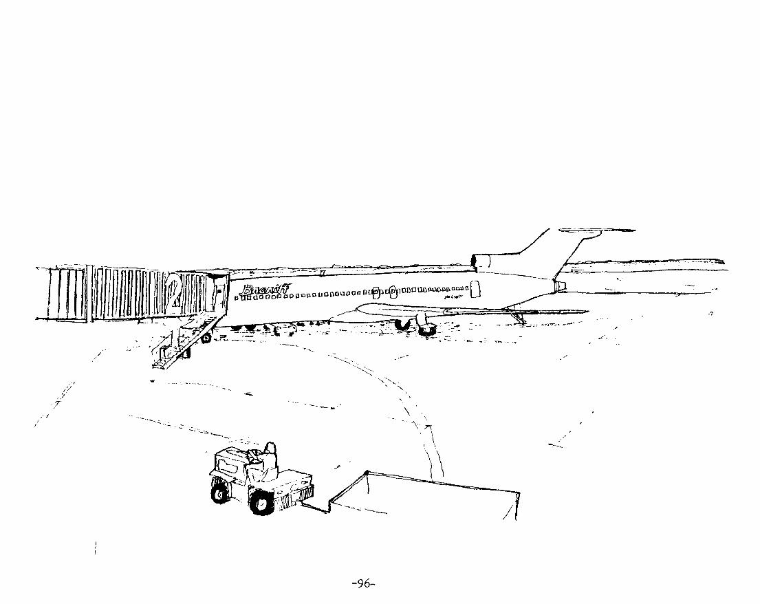
u. u o o o a o o « D f > t ^ l O C ° ' ^ « * X " ' D
•- \
-96-

CARGO
2.1 Access Interface
2.11 & 2.12 Parking & Loading Docks - the need
for 400 feet of frontage for cars and truck docks.
Each of the four zones have one loading dock and a
36 in. door. Estimated Cargo frontage by using
percentage of square footage of areas.
Airline Cargo Zone 35 ft.® 140 ft.
Mechanical 27 ft.@ 81 ft.
Kitchen 30 ft.
Employee 60 ft.
Equipment 20 ft.
Rental Space 70 ft.
Total 400 ft.
Overhead doors are to be used and all doors and
entries require to well marked for guidance.
2.2 Administrative - There will be four air
line cargo zones, each with its own baggage con
veyance from ticket sales. To assure flexibility
in this area only temporary pai-titions within each
zone will be used. Of the total sqviare footage
required by the airline company, 30 % is ad
ministrative. For a single zone exist, if they
handle more than 25 % of the airports cargo move
ment. Administrative office space required for
a typical day are:
Small package check/claim
Receptionist
Dispatch/Communications
Records
Access to apron
2.3 Handling - A typical cargo zone requires
25^ of its total sqare footage for handling.
2.31 Small Package Check/Claim - Space for
people to park their vehicles, walk in and"
check or claim a package. This type of space
requires a 48 in. h i ^ counter and access to store-
age area. Some seating may be supplied.
2.32 Docks - For larger packages of truck
deliveries a loading dock is required. Adequate
area is needed for movement and temporary
-97-

Storage of goods. Should comply with all air
port building codes. Area must be well lit both
Inside and out.
2.33 Ba^age Conveyance - See system performance.
Adequate space is needed for unloading baggage off
of conveyor belt to carts and sorting.
2.34 Plane Loading - Overhead doors (2) located
on the apron side are required for each typical
zone. Space for parking carts and trucks is also
required on the interior. Space should be well
vented for operation of butane propelled lifts
and moving equipment.
2.4 Storage - The remaining 55% of a typical
cargo zone is used for storage.
2.41 Short Term - storage basically is area
designated for artlq^lg which will be shipped again
with in six operational hours. The majority
of the area is used to place baggage after its
been sorted and is waiting to be loaded on a cart.
2.42 Long Term - storage of articles which
will not be shipped within the next six oper
ational hours. Use of space will be organized
for quick and easy access to any girticle.
2.43 Special - storage of items such as
live animals, perishible goods or any item tha
requires special temperature control. Also
storage of valuable goods.
2.44 Lost/Found - long term storage and
filling of items which have been miss shipped
or lost.
2.5 Customer and Personal Accomodations
Small break area for coffee, water, etc. each
zone should have a restroom and easy access
to stairs and elevators.
3.
3.1
ADMINISTRATION
Offices
Spaces required for administration area:
Receptionist Secretaries Director Asst. Director
-98-

FAA office Conference Room Work and Storage Room Engineer Break Room
Access by stairs and elevators and corridors
to airline offices, cargo, and passenger ticket
ing and departure lobbies.
3*2 TV/Radio/Press Room - for use of inter
viewing by any media of the press.
Special conditions required for this space
of 700 sq. ft. :
TV Lighting Public Address System Seating Storage
Special Acoustical
For more data see system performances.
3.3 Meeting Rooms - Space of 1450 sq. ft. for
meetings which is also capable of being par
titioned off into smaller spaces of 96O and 480
sq. ft.. Storage space is required for chairs,
tables, etc.. Adequate coat storage is also re
quired for each smaller space.
3«4 Communications - A dispatch station for
Administrators. Incorporated near receptionist
and director's office.
-QQ-

4. OTHER
4.1 Mechanical Rooms - to contain all air
handling equipment, plumbing, service sink and
electric and lifting panels. Three zones are to
be used each 1450 sq. ft. for a total of 4350
sq. ft.. All mechanical equipment is to be hid
den from air and ground.
4.2 Communications
4.21 Switch Room - 640 sq. ft.
4.22 Generator Room - power supply to insvire
operation during a black-out. Space needed for
equipment - 240 sq. ft.
4.23 Paging Equipment - 240 sq. ft.
4.24 Phone Equipment - 280 sq. ft.
4.3 Janitor Supplies - for storage of all
janitor supplies and equipment needed to maintain
building. - 280 sq. ft.
4.4 Employee Lounge - space for airport
employees to change clothes, take a break, eat,
rest, etc. Space requires:
Lounge BreaJt Area Dressing Rooms w/Showers Restrooms
Lockers
Total square footage - 1000 feet.
4.5 Kitchen Services - bulk storage of a]
frozen, refrigeration and dry goods for kltcl:
and cocktail lounge.
4.6 Rental Space - Further expsinsion of
airline cargo zones - 4750 sq. ft.
4.7 Deplaned Baggage Check - unloading ax
for baggage from cargo carts to baggage claln
conveyors - 1200 sq. ft.
-100-

' t ? ^ : . ^ ^ " ^

COST ANALYSIS
-101-

Financing & Ownership
Gregg County Airport is presently under owner
ship of individual authorities that run the
airport on behalf of one local authority. This
is a step in the right direction being the trend
toward public ownership is international, and not
private. In order to Insure the successfulness
funding of the new air terminal ownership ml^t
possible by shifted to Quasi-Governmental Organ
izations (by shared ownership with other East
Texas Counties) or affiliation with DFW International.
The Airport to some degree will be self-
financing, with a healthy return on invested cap
ital. The initial capital requirement for the con
struction and development of the airport cannot
be financed by its ovm resources. Therefore the
new terminal development proceeds on the basis on
money aggregated from a variety of sources such as
general obligation bonds, self liquidating general
obligation bonds, revenue bonds, local taxes,
and state and federal grants.
1) General Obligation Bonds - an investment se
curity that can be sold at a low interest rate;
lowering the limited total available debt, level.
2) Self Liquidating General Obligation Bonds -
secured in the same manner as General Obligation
Bonds; however with the recognition that the bond
is financing and a revenue reducing project,
the issue does not contribute toward the overall
debt limitation set by Texas.
3) Revenue Bond - the entire debt service is paid
from project revenues, but is subject to the
general debt limitation. This bond also have a
higher interest rate and can be sold on the open
market.
-102-

4) Local Governmental Taxes
5) State Finance - usual match. Federal funds 5O-5O
or in the case of no Federal funds, local.
6) Federal Grants - Are available through Federal
Airport Act of 1946 as amended in I955, 1959, 196I,
1964, 1966; and currently by the Airport and Air
way Development Act of I970 as amended in I976; and
the Airport Development Acceleration Act of I973.
Value Engineering - can be achieved in a
variety of methods.
*Planning: To meet precise objects.
*Arx-angement: Simplification of structure
by use of conponat parts
*Engineering Services: Omission of air condition
ing or other services in certain areas and utilization
of passive solar resources.
*SimplificatiQn of design and use of stand
ardized conponants.
-i03-

COST ANALYSIS
Average cost of new Airport te rminals b u i l t between
1975-77; $38-$43/sq. f t .
Use ($40/sq . f t . ) (86 ,000 s q . f t . ) equals $3,440,000
At iZ/o I n f l a t ed r a t e / a f t e r 5 years (60^) to br ing
up to 1980 cos t ; and 14^ expected cost to mid-point
of const ruct ion (2 years) i s (289S).
.88 X $3,440,000 = $3,027,200 $3,440,000
Total Estimated $6,467,200 cost of construction
Tajclway -Aprons -P, '"king Lots -Access Road -Signage & Lifting -Site Development/landscaping
Cost Breakdown of Terminal Bjiilding
Item Cost
S t r u c t u r a l Elements
Substruct\ ire
Frame & Upper Floors Roof
3.3 $213,400
34.8 $2,250,600
2.8 $181,100
Carpentry & Millwork 2.9
Walls 3.0
Windows & Doors 6.2
Subtotal
$187,500
$187600
$401000
53^ $3,427,600
Finishes & Fittings
Wall 3.0 $194,000
Floor 2.7 $174,600
Gelling 2.3 $148,800
Hardware & Misc. 1.0 64,700
Fittings 4.0 $258,700
Subtotal
Furnishings
Services
Baggage Conveyor
Elevators
Mechanical
Electrical
Bond & Administration
Subtotal
Total
13.0 $840,700
4 .3 $278,100
1.2 $77,600
1.0 $64,700
14.1 $1,080,000
8.9 $575,580
4 .5 $291,000
29.7 $1,920,800
100^ $6,467,200
-104-

Revenues & Expenditures
Since, the feasibility of building and devel
oping a terminal relies greatly on the anticipated
revenue and expenditures, the financial aspect
of airport planning must take into consideration
both revenues and expenses; those two principle
divisions may be further grouped into the oper
ational & non-operational areas.
Operating Revenues - 98.5%
1) Landing Area
Landing Fees
Parking Fees
2) Concessions
Specialty Areas; news stands, food and drinks
Leisure Areas; television, observation
Travel Services; lockers, washrooms, rental
cars, rest areas, telephones.
personal services; barber, valet services,
off-terminal facilities; office rental, advertising.
3) Airline Leased Areas
Officers
Managers
Ticket & Check-in counters
Operations
Maintalnance Areas
Cargo Areas
4) Other Leased Areas
Industrial Areas
Fuel & Servicing Facilities
Fixed Base Operations
freight forwarders
Ware-housing
Land Use Rights-oil, farming, cattle, etc..
5) Other Operating Revenue
Equipment Rental
Resale of Utilities
Baggage Handling
Non-operating Revenues 1,5%
All income that occurs from sources that
are not directly connected to airport functions.
example: rental of non-airport land (LTV) or
from interest on accvimulated surpluses.
EXPENDITURES
Operational Expenses 86.4%
1) Maintalnance Cost
Up Keep of Facilities
Landing Areas; Runways, tapciways, aprons,
lighting equipment, etc.
.05-

Terminal Area; buildings, utilities, bag
gage handling, access routes, grounds, etc.
Hangers
Cargo Area
2) Operating Cost
Admini stration
Staffing
Utilities
Security
Non-pperatlonal Expenses 13.6%
The unescapable cost that would have to be met
even if the airport ceased operation. Typically
they include the interest payments on outstanding
capital debt and amortization charges on fixed
assets such as runways, aprons, buildings, and other
infrastructures.
-106-


BIBLIOGRAPHY
-107-

BIBLIOGRAPHY
1. Airport Building Code
2. Airport Fire Code
3. Blankenship, Edward G., The Airport. New York; Praeger Praeger Publishers, 1974.
3.5 Bollinger, Lynn L. , Terminal Airport Fineincing and Management., Andover, Mass. The Andover Press, 1946
4. Civil Aeronautics Board, In the Matter of Applica.tional Air Service In Texas, Oklahoma
and Louisiana. Docket No. 3246, Washington D.G., 1952.
5. Civil Aeronautics Board, In the Matter of the Gulf States-Midwest Points Service Investigation.
Docket No. 17726, Washington D.C., I968
6. Civil Aeronautics Board, In the Matter of the Application of Trans-Texa^ Airways for an Amend
ment of its Certificate of Public Convenience and Necessity for Route No. 82. Docket No. 7939,
Washington, D.C., 1957.
7. Dodge Construction Systems Costs, 1978, 76,77,79.
'^.^ Egan, David M., Concepts in Thermal Comfort, Prentice-Hall International, London, 1975-
8. F.A.A. Advisory Circulors and Federal Aviation Regulations.
9. F.A.A. Activity Statistics Projections 1979 - 1990.
10. Frederick, John H., Airport Management. Chicago: Richard D. Irwin, Inc., 1949-
11. Froesch, Charles and Prokasch, Walther. Airport Planning. New York: McGraw-Hill Book
Company., 1975.
11.5 Godfrey, Robert Sturgis, Building Construction Cost Data, 37 Edition, 1979.
12. Horonjeff. Robert., Planning and Design of Airports. Second Edition, New York; McGraw-
Hill Book Go., 1975.
-108-

12.5 Howard, George P., ed., Airport Economic Planning.. Cambridge, Mass. the MIT Press.
13. Landscape Planning for Energy Conservation. Enviornmental Design Press, 1977
14. Longvlew Chamber of Commerce, History of Longvlew.
14.5 Proceedings of the fifth World Airport Conference on Technological and Economic Change,
Airports. The Challenging Future.
15« U.S. Department of Transportation, F.A.A., Calculations of Maximum A-Wei^ted Sound Levels (DBA)
Resulting from Civil Aircrafts Operations. Office of Enviornmental Quality, Washington, D.C.,
Jime 1978.
2.5 Wright, Ashford, Airport Engineering. John Wiley & Sons. New York, 1979.
J. 7


APPENDIX

AIRCRAFT TY?S
H 'J < — — <
?-:-i-227
:-:ELI:C?TZ?3
r s - i i 2C9-iO 3707-220
3 - 2 0
372-
"VS30
: v - 2 Q 0
0C6
roS-io
r«g«»iiiiri-<iii -
MILES (1,C00)
'L.hJi: r, 1
[,n'^,i7' I
2 2 s : L.irjbJtKrj
UJUbUSS
(:CMSTRAINSI3 3Y USZR) 5 6 ^ 3 '
rizj
:z:3
K^'wriT -""4'"^^'-^'-''-*^'i..-i '-•
^ ^ —nrrrr?! r scd^sa^Bzs
^bQEIR
'iiiiti imv ijffMi f I'lutUuri rtif ' L vrvMfc'Ji
s a
Aittfuft ranqa. MILES (1 ,000)
X

1200
1000
800
NUMBER OF 500
PASSENGERS
400
200
0 1930 1940
Passangar-aiicraft capacitY growth tiand.
1950 1960 1970 YEAR ENTER SERVICE
1980
I ro I
GROSS WEIGHT (100.000)
12-1
10
KG
4 -
0-'
25
20
15
LB
10
1930
GrastHwaight growth.
SUBSONIC JETS LOW BYPASS RATIO ENGINE -
O C - 9 - 3 0 DC 8-50 '3'-»00 707.320B -0C-9--'0
ADVANCED SUBSONIC JETS-HIGH BYPASS RATIO ENGINE-
PISTON ' ^ AIRCRAFT
1049G
OC
"-^,7-.; Lj i .o*^*<^^a^\ \ . 1 0 0 » « ^ 7 . 2 0 0 V ^ S 5ST \
| \P*SSfNGER AIRCRAtT J V S - ^ D C I O - Z O / J O — — ~
* » 0 C 6 ^ * « 3 « 0 ° ^
' D C I O I O / L I O U ( ^ CONCORDE
LONG HANG£ SHORT MEDIUM RANGE
1940 1950 1960 YEAR ENTER SERVICE
1970 1980
OVERALL LENGTH 500
140
120
100 -\
80
60
40
20 i
I
oJ
I/) a:
400
300
200
100
0 "-1930 1940
OwfalLlangth giowth varwt ran.
1950 I960 1970
YEAR ENTER SERVICE 1980

WING SPAN
120 n 400
100
80
60
40
20
0
300
200
100
1930 1940
Wiogspan giowth versus ysai.
1950 1950 1970 YEAR ENTER SERVICE
1980
X » I 1
OVERALL LENGTH 350 r
100 -]
j 300
.80
5 40
?0
0 ->
200
100
0 LB 0
•, 72 7 iOO XV^-DC-T/IOASG \ ^ ^ — D : 9-10 ' "^ DC 6. 737 100
— DC 3
10 15
KG 0 1 2 3 •i 5 6
GROSS WEIGHT (100.000)
Ovarill-langth growth itnui gross waight
20
WING SPAN l20 -1 400
IOC
8C -I
i/i
^ 60
40
20 -
0 -
300
200
100
I - 707 3 2 0 6 . 0 C . 4 1 / OC.8-50 , -DC 6 i / r - O C - 8 . 6 3 "•
' , '—10490/ ' /
500
w^z ;//;'
• 747 . 0 0 - 1 0 - 2 0 / 3 0
OCIO 1 0 / (»U S. SST' 7 0 7 . 1 2 0 ^ - 1 ° "
727 lOJ •^J CONCORDE
737 100 DC 9 .30
0 LB 0 a 10 12 u 16
KG 0 3 4 5 6 GROSS WEIGHT (100.000)
18 20
Vingspao growth «anus grou waight.

I
1
Ramp araa tiaiui.
JOOO
9 0 0
800
700
600
NUMBER • 500 OF
PASSENGERS 400
300
200
100
0
A L L CCO*«Oft«Y S C A T I M G - S O B S O W I C 5 I W C L E C L A S S SE.JfcTli4C - S S T S
MULTI DECK AIRPUAHES-
I Hh
_707 12 1049G—. \
n
m W III
mm^ rjfm
747
-Vr-
DC-lO/L-lOU ! - I i—<*>U.S. SST •
OC-6—. \ ' \ DC.8 _ 0 C - 4 = - > ^ W ^ 73 7 .100- , \ \ ^i.,®
707320B , - • _ _ _ CONCORDE _:
DC.3' h—DC.9-30 I
SQ FT 0
SQ METERS ^
10 20 30 40 50 60 70 80 90 100
SILL HEIGHT
ABOVE GROUND
12 -1 40
10 -
(/I
h- 6 UJ
30
- tii 20
2 -
0 -J 1930
Passengst dootsill-height trend.
2 3 4 5 6 7
RAMP A R E A / A I R C R A F T (lOOO)
MULTI-DECK-
U.S. SST—,
CONCORDE
1049G- 7 0 7 - 1 2 0 - i747.200B.C-i
OC-8 50l( ^ ^ ^ _ ^ 7 0 7 . 3 2 0 B h 7 4 7 . 1 0 0 ^ , W - ' : ^ D e C K
DC 10/ • DC-8.63 L 1011
DC-4
,DC-6 oDC-?' • 737-100 340 • 727100 • V ^ V c 9 30
1940 1950 1960 1970 YEAR ENTER SERVICE
1980
AVERAGE WAKE VELOCITV
— 100 150-
100-
X r 2
50
8 0
60
40
20
L_ 0
r40TE- VELOCITY IS AVERAGED OVER DIAMETER OF WAKE.
I VELOCITY ON CENTER LINE OF i WAKE WILL BE HIGHER.
200 FT BEHIND ENGINE (61 M) I i
yr- 6 8 10 12 14 16 LB 0
KG d ^ ' ^ ' l 3 4 6 6 T
GROSS WEIGHT dOCOOOi
bUCMtWl l»l lAhaus' cli«>»<i»''«'''-« '"••'• •'^•" "•"•••
EXHAUST WAKE DIAMETER
1 6 0 i
40
soul a:
•20-
10-
120
t : 80
40
200 FT BEHIND ENGI'^r (61 Ml ,
100 FT BEHIND ENGINE (30.5 Ml
1 !
LB 0 ^ 4 5 8 10 12 14 15
KG O " ^ 3 4 5 6 7 8
GROSS WEIGHT 1 0 0 . 0 0 0 -

-a-'xcE-e
zzrA
BOOT ;"?i*55 J . H^
( ! . /
(I > r
I I I !
I ! I
n k
/
P' V
[ I ' I
i.r.-
z'
< 2.-'k2,
i ^^ : " ! u !
\
X, :
\
V " ' " - - - - J
" -^ f^g^?? . :^ iXiM'*?***"'
Jiu:' j :iiEinin_:

D C 5 3o
O C I O

I 00 I
'; f B 7 0 7 aooB
B 7 S 7 a o o e « ia H u «

X m
\ 1
B 7 3 7 a a a

I
o X

m
I
a 3 7 0 7