Embed Size (px)
Citation preview

Filename: LMAPGTTL.DOC Project: Template: FRONTA1.DOT Author: Bart Simpson, Who the Hell Are You? Last Saved By: Mike Eddy Revision #: 16 Page: 1 of 1 Printed: 10/02/00 04:19 PM
Microsoft ® MASM Assembly-Language Development System Version 6.1
For MS-DOS ® and Windows ™ Operating Systems
Programmer’s Guide
Microsoft Corporation
Filename: LMAPGCPY.DOC Project: Template: FRONTA1.DOT Author: Ruth L Silverio Last Saved By: Mike Eddy Revision #: 6 Page: 2 of 1 Printed: 10/02/00 04:21 PM
Information in this document is subject to change without notice. Companies, names, and data used in examples herein are fictitious unless otherwise noted. No part of this document maybe reproduced or transmitted in any form or by any means, electronic or mechanical, for any purpose, without the express written permission of Microsoft Corporation. ©1992 Microsoft Corporation. All rights reserved. Microsoft, MS, MS-DOS, XENIX, CodeView, and QuickC are registered trademarks and Microsoft
QuickBasic, QuickPascal, Windows and Windows NT are trademarks of Microsoft Corporation in the USA and other countries.
U.S. Patent No. 4,955,066 Hercules is a registered trademark of Hercules Computer Technology. IBM, PS/2, and OS/2 are registered trademarks of International Business Machines Corporation. Intel is a registered trademark of Intel Corporation. NEC and V25 are registered trademarks and V35 is a trademark of NEC Corporation.
Document No. DB35747-1292 Printed in the United States of America.
iii
Filename: LMAPGTOC.DOC Project: Template: FRONTA1.DOT Author: Don Hayward Last Saved By: Ruth L Silverio Revision #: 18 Page: 3 of 1 Printed: 10/02/00 04:19 PM
Contents
Introduction. . . . . . . . . . . . . . . . . . . . . . . . . . . . . . . . . . . . . . . . . . . . . . . . . . . . xiii New and Extended Features in MASM 6.1 . . . . . . . . . . . . . . . . . . . . . . . . xiii
MASM Features New Since Version 5.1 . . . . . . . . . . . . . . . . . . . . . . . . xiv MASM Features New Since Version 6.0 . . . . . . . . . . . . . . . . . . . . . . . . xv ML and MASM Command Lines . . . . . . . . . . . . . . . . . . . . . . . . . . . . . xvi Compatibility with Earlier Versions of MASM . . . . . . . . . . . . . . . . . . . . xvi
A Word About Instruction Timings . . . . . . . . . . . . . . . . . . . . . . . . . . . . . xvii Books for Further Reading . . . . . . . . . . . . . . . . . . . . . . . . . . . . . . . . . . . xviii Document Conventions . . . . . . . . . . . . . . . . . . . . . . . . . . . . . . . . . . . . . . xix Getting Assistance and Reporting Problems . . . . . . . . . . . . . . . . . . . . . . . . xx
Chapter 1 Understanding Global Concepts . . . . . . . . . . . . . . . . . . . . . . . . . . . . . 1 The Processing Environment . . . . . . . . . . . . . . . . . . . . . . . . . . . . . . . . . . . 1
8086-Based Processors . . . . . . . . . . . . . . . . . . . . . . . . . . . . . . . . . . . . . 2 Operating Systems . . . . . . . . . . . . . . . . . . . . . . . . . . . . . . . . . . . . . . . . 4 Segmented Architecture . . . . . . . . . . . . . . . . . . . . . . . . . . . . . . . . . . . . . 5 Segment Protection . . . . . . . . . . . . . . . . . . . . . . . . . . . . . . . . . . . . . . . . 6 Segmented Addressing. . . . . . . . . . . . . . . . . . . . . . . . . . . . . . . . . . . . . . 7 Segment Arithmetic . . . . . . . . . . . . . . . . . . . . . . . . . . . . . . . . . . . . . . . . 7
Language Components of MASM . . . . . . . . . . . . . . . . . . . . . . . . . . . . . . . . 8 Reserved Words . . . . . . . . . . . . . . . . . . . . . . . . . . . . . . . . . . . . . . . . . . 8 Identifiers . . . . . . . . . . . . . . . . . . . . . . . . . . . . . . . . . . . . . . . . . . . . . . . 9 Predefined Symbols . . . . . . . . . . . . . . . . . . . . . . . . . . . . . . . . . . . . . . 10 Integer Constants and Constant Expressions . . . . . . . . . . . . . . . . . . . . . 11 Operators . . . . . . . . . . . . . . . . . . . . . . . . . . . . . . . . . . . . . . . . . . . . . . 13 Data Types. . . . . . . . . . . . . . . . . . . . . . . . . . . . . . . . . . . . . . . . . . . . . 14 Registers . . . . . . . . . . . . . . . . . . . . . . . . . . . . . . . . . . . . . . . . . . . . . . 16 Statements . . . . . . . . . . . . . . . . . . . . . . . . . . . . . . . . . . . . . . . . . . . . . 21
The Assembly Process . . . . . . . . . . . . . . . . . . . . . . . . . . . . . . . . . . . . . . . 22 Generating and Running Executable Programs . . . . . . . . . . . . . . . . . . . . 23 Using the OPTION Directive . . . . . . . . . . . . . . . . . . . . . . . . . . . . . . . . 24 Conditional Directives . . . . . . . . . . . . . . . . . . . . . . . . . . . . . . . . . . . . . 28
Chapter 2 Organizing Segments . . . . . . . . . . . . . . . . . . . . . . . . . . . . . . . . . . . . 31 Physical Memory Segments . . . . . . . . . . . . . . . . . . . . . . . . . . . . . . . . . . . 32 Logical Segments. . . . . . . . . . . . . . . . . . . . . . . . . . . . . . . . . . . . . . . . . . . 32 Using Simplified Segment Directives . . . . . . . . . . . . . . . . . . . . . . . . . . . . . 33
iv Contents
Filename: LMAPGTOC.DOC Project: Template: FRONTA1.DOT Author: Don Hayward Last Saved By: Ruth L Silverio Revision #: 18 Page: 4 of 2 Printed: 10/02/00 04:19 PM
Defining Basic Attributes with .MODEL . . . . . . . . . . . . . . . . . . . . . . . . 34 Specifying a Processor and Coprocessor . . . . . . . . . . . . . . . . . . . . . . . . 38 Creating a Stack. . . . . . . . . . . . . . . . . . . . . . . . . . . . . . . . . . . . . . . . . . 38 Creating Data Segments . . . . . . . . . . . . . . . . . . . . . . . . . . . . . . . . . . . . 39 Creating Code Segments . . . . . . . . . . . . . . . . . . . . . . . . . . . . . . . . . . . . 40 Starting and Ending Code with .STARTUP and .EXIT . . . . . . . . . . . . . . 41
Using Full Segment Definitions . . . . . . . . . . . . . . . . . . . . . . . . . . . . . . . . . 44 Defining Segments with the SEGMENT Directive. . . . . . . . . . . . . . . . . . 44 Controlling the Segment Order . . . . . . . . . . . . . . . . . . . . . . . . . . . . . . . 47 Setting the ASSUME Directive for Segment Registers . . . . . . . . . . . . . . . 49 Defining Segment Groups . . . . . . . . . . . . . . . . . . . . . . . . . . . . . . . . . . . 51
Chapter 3 Using Addresses and Pointers . . . . . . . . . . . . . . . . . . . . . . . . . . . . . 53 Programming Segmented Addresses . . . . . . . . . . . . . . . . . . . . . . . . . . . . . . 53
Initializing Default Segment Registers. . . . . . . . . . . . . . . . . . . . . . . . . . . 53 Near and Far Addresses . . . . . . . . . . . . . . . . . . . . . . . . . . . . . . . . . . . . 57
Operands . . . . . . . . . . . . . . . . . . . . . . . . . . . . . . . . . . . . . . . . . . . . . . . . . 60 Register Operands . . . . . . . . . . . . . . . . . . . . . . . . . . . . . . . . . . . . . . . . 61 Immediate Operands . . . . . . . . . . . . . . . . . . . . . . . . . . . . . . . . . . . . . . 61 Direct Memory Operands . . . . . . . . . . . . . . . . . . . . . . . . . . . . . . . . . . . 62 Indirect Memory Operands . . . . . . . . . . . . . . . . . . . . . . . . . . . . . . . . . . 64
The Program Stack. . . . . . . . . . . . . . . . . . . . . . . . . . . . . . . . . . . . . . . . . . 71 Saving Operands on the Stack. . . . . . . . . . . . . . . . . . . . . . . . . . . . . . . . 71 Saving Flags on the Stack . . . . . . . . . . . . . . . . . . . . . . . . . . . . . . . . . . . 73 Saving Registers on the Stack (80186–80486 Only). . . . . . . . . . . . . . . . . 74
Accessing Data with Pointers and Addresses . . . . . . . . . . . . . . . . . . . . . . . . 74 Defining Pointer Types with TYPEDEF . . . . . . . . . . . . . . . . . . . . . . . . 75 Defining Register Types with ASSUME. . . . . . . . . . . . . . . . . . . . . . . . . 77 Basic Pointer and Address Operations . . . . . . . . . . . . . . . . . . . . . . . . . . 78
Chapter 4 Defining and Using Simple Data Types . . . . . . . . . . . . . . . . . . . . . . . 85 Declaring Integer Variables . . . . . . . . . . . . . . . . . . . . . . . . . . . . . . . . . . . . 85
Allocating Memory for Integer Variables . . . . . . . . . . . . . . . . . . . . . . . . 85 Data Initialization . . . . . . . . . . . . . . . . . . . . . . . . . . . . . . . . . . . . . . . . . 87
Working with Simple Variables . . . . . . . . . . . . . . . . . . . . . . . . . . . . . . . . . 88 Copying Data. . . . . . . . . . . . . . . . . . . . . . . . . . . . . . . . . . . . . . . . . . . . 89 Adding and Subtracting Integers . . . . . . . . . . . . . . . . . . . . . . . . . . . . . . 92 Multiplying and Dividing Integers. . . . . . . . . . . . . . . . . . . . . . . . . . . . . . 95
Manipulating Numbers at the Bit Level. . . . . . . . . . . . . . . . . . . . . . . . . . . . 98 Logical Instructions . . . . . . . . . . . . . . . . . . . . . . . . . . . . . . . . . . . . . . . 99 Shifting and Rotating Bits . . . . . . . . . . . . . . . . . . . . . . . . . . . . . . . . . . 100
Contents v
Filename: LMAPGTOC.DOC Project: Template: FRONTA1.DOT Author: Don Hayward Last Saved By: Ruth L Silverio Revision #: 18 Page: 5 of 3 Printed: 10/02/00 04:19 PM
Multiplying and Dividing with Shift Instructions . . . . . . . . . . . . . . . . . . 102
Chapter 5 Defining and Using Complex Data Types. . . . . . . . . . . . . . . . . . . . . 105 Arrays and Strings . . . . . . . . . . . . . . . . . . . . . . . . . . . . . . . . . . . . . . . . . 105
Declaring and Referencing Arrays. . . . . . . . . . . . . . . . . . . . . . . . . . . . 105 Declaring and Initializing Strings . . . . . . . . . . . . . . . . . . . . . . . . . . . . . 108 Processing Strings . . . . . . . . . . . . . . . . . . . . . . . . . . . . . . . . . . . . . . . 110
Structures and Unions . . . . . . . . . . . . . . . . . . . . . . . . . . . . . . . . . . . . . . 117 Declaring Structure and Union Types . . . . . . . . . . . . . . . . . . . . . . . . . 118 Defining Structure and Union Variables. . . . . . . . . . . . . . . . . . . . . . . . 121 Referencing Structures, Unions, and Fields . . . . . . . . . . . . . . . . . . . . . 126 Nested Structures and Unions . . . . . . . . . . . . . . . . . . . . . . . . . . . . . . 128
Records . . . . . . . . . . . . . . . . . . . . . . . . . . . . . . . . . . . . . . . . . . . . . . . . 129 Declaring Record Types . . . . . . . . . . . . . . . . . . . . . . . . . . . . . . . . . . 130 Defining Record Variables . . . . . . . . . . . . . . . . . . . . . . . . . . . . . . . . . 131 Record Operators . . . . . . . . . . . . . . . . . . . . . . . . . . . . . . . . . . . . . . . 133
Chapter 6 Using Floating-Point and Binary Coded Decimal Numbers . . . . . . . 135 Using Floating-Point Numbers . . . . . . . . . . . . . . . . . . . . . . . . . . . . . . . . 136
Declaring Floating-Point Variables and Constants . . . . . . . . . . . . . . . . . 136 Storing Numbers in Floating-Point Format. . . . . . . . . . . . . . . . . . . . . . 138
Using a Math Coprocessor . . . . . . . . . . . . . . . . . . . . . . . . . . . . . . . . . . . 139 Coprocessor Architecture. . . . . . . . . . . . . . . . . . . . . . . . . . . . . . . . . . 140 Instruction and Operand Formats . . . . . . . . . . . . . . . . . . . . . . . . . . . . 141 Coordinating Memory Access. . . . . . . . . . . . . . . . . . . . . . . . . . . . . . . 145 Using Coprocessor Instructions . . . . . . . . . . . . . . . . . . . . . . . . . . . . . 146
Using An Emulator Library. . . . . . . . . . . . . . . . . . . . . . . . . . . . . . . . . . . 155 Using Binary Coded Decimal Numbers . . . . . . . . . . . . . . . . . . . . . . . . . . 156
Defining BCD Constants and Variables . . . . . . . . . . . . . . . . . . . . . . . . 157 BCD Calculations on a Coprocessor . . . . . . . . . . . . . . . . . . . . . . . . . . 157 BCD Calculations on the Main Processor . . . . . . . . . . . . . . . . . . . . . . 158
Chapter 7 Controlling Program Flow. . . . . . . . . . . . . . . . . . . . . . . . . . . . . . . . 161 Jumps. . . . . . . . . . . . . . . . . . . . . . . . . . . . . . . . . . . . . . . . . . . . . . . . . . 161
Unconditional Jumps . . . . . . . . . . . . . . . . . . . . . . . . . . . . . . . . . . . . . 162 Conditional Jumps. . . . . . . . . . . . . . . . . . . . . . . . . . . . . . . . . . . . . . . 164
Loops . . . . . . . . . . . . . . . . . . . . . . . . . . . . . . . . . . . . . . . . . . . . . . . . . . 172 Loop-Generating Directives . . . . . . . . . . . . . . . . . . . . . . . . . . . . . . . . 173 Writing Loop Conditions . . . . . . . . . . . . . . . . . . . . . . . . . . . . . . . . . . 178
Procedures . . . . . . . . . . . . . . . . . . . . . . . . . . . . . . . . . . . . . . . . . . . . . . 180 Defining Procedures . . . . . . . . . . . . . . . . . . . . . . . . . . . . . . . . . . . . . 180

vi Contents
Filename: LMAPGTOC.DOC Project: Template: FRONTA1.DOT Author: Don Hayward Last Saved By: Ruth L Silverio Revision #: 18 Page: 6 of 4 Printed: 10/02/00 04:19 PM
Passing Arguments on the Stack . . . . . . . . . . . . . . . . . . . . . . . . . . . . . 182 Declaring Parameters with the PROC Directive . . . . . . . . . . . . . . . . . . 184 Using Local Variables. . . . . . . . . . . . . . . . . . . . . . . . . . . . . . . . . . . . . 188 Creating Local Variables Automatically . . . . . . . . . . . . . . . . . . . . . . . . 190 Declaring Procedure Prototypes . . . . . . . . . . . . . . . . . . . . . . . . . . . . . 193 Calling Procedures with INVOKE . . . . . . . . . . . . . . . . . . . . . . . . . . . . 194 Generating Prologue and Epilogue Code. . . . . . . . . . . . . . . . . . . . . . . . 198
MS-DOS Interrupts . . . . . . . . . . . . . . . . . . . . . . . . . . . . . . . . . . . . . . . . 204 Calling MS-DOS and ROM-BIOS Interrupts . . . . . . . . . . . . . . . . . . . . 204 Replacing an Interrupt Routine . . . . . . . . . . . . . . . . . . . . . . . . . . . . . . 206
Chapter 8 Sharing Data and Procedures Among Modules and Libraries . . . . . 211 Selecting Data-Sharing Methods. . . . . . . . . . . . . . . . . . . . . . . . . . . . . . . . 211 Sharing Symbols with Include Files . . . . . . . . . . . . . . . . . . . . . . . . . . . . . 212
Organizing Modules . . . . . . . . . . . . . . . . . . . . . . . . . . . . . . . . . . . . . . 212 Declaring Symbols Public and External . . . . . . . . . . . . . . . . . . . . . . . . 214 Positioning External Declarations. . . . . . . . . . . . . . . . . . . . . . . . . . . . . 228
Using Alternatives to Include Files . . . . . . . . . . . . . . . . . . . . . . . . . . . . . . 219 PUBLIC and EXTERN . . . . . . . . . . . . . . . . . . . . . . . . . . . . . . . . . . . 220 Other Alternatives . . . . . . . . . . . . . . . . . . . . . . . . . . . . . . . . . . . . . . . 221
Developing Libraries . . . . . . . . . . . . . . . . . . . . . . . . . . . . . . . . . . . . . . . . 221 Associating Libraries with Modules . . . . . . . . . . . . . . . . . . . . . . . . . . . 222 Using EXTERN with Library Routines . . . . . . . . . . . . . . . . . . . . . . . . 223
Chapter 9 Using Macros . . . . . . . . . . . . . . . . . . . . . . . . . . . . . . . . . . . . . . . . . 225 Text Macros. . . . . . . . . . . . . . . . . . . . . . . . . . . . . . . . . . . . . . . . . . . . . . 226 Macro Procedures . . . . . . . . . . . . . . . . . . . . . . . . . . . . . . . . . . . . . . . . . 226
Creating Macro Procedures. . . . . . . . . . . . . . . . . . . . . . . . . . . . . . . . . 227 Passing Arguments to Macros . . . . . . . . . . . . . . . . . . . . . . . . . . . . . . . 228 Specifying Required and Default Parameters . . . . . . . . . . . . . . . . . . . . 229 Defining Local Symbols in Macros . . . . . . . . . . . . . . . . . . . . . . . . . . . 232
Assembly-Time Variables and Macro Operators . . . . . . . . . . . . . . . . . . . . 233 Text Delimiters and the Literal-Character Operator . . . . . . . . . . . . . . . . 234 Expansion Operator . . . . . . . . . . . . . . . . . . . . . . . . . . . . . . . . . . . . . . 235 Substitution Operator . . . . . . . . . . . . . . . . . . . . . . . . . . . . . . . . . . . . . 237
Defining Repeat Blocks with Loop Directives . . . . . . . . . . . . . . . . . . . . . . 239 REPEAT Loops. . . . . . . . . . . . . . . . . . . . . . . . . . . . . . . . . . . . . . . . . 240 WHILE Loops. . . . . . . . . . . . . . . . . . . . . . . . . . . . . . . . . . . . . . . . . . 241 FOR Loops and Variable-Length Parameters . . . . . . . . . . . . . . . . . . . . 242 FORC Loops . . . . . . . . . . . . . . . . . . . . . . . . . . . . . . . . . . . . . . . . . . . 244
String Directives and Predefined Functions . . . . . . . . . . . . . . . . . . . . . . . . 245
Contents vii
Filename: LMAPGTOC.DOC Project: Template: FRONTA1.DOT Author: Don Hayward Last Saved By: Ruth L Silverio Revision #: 18 Page: 7 of 5 Printed: 10/02/00 04:19 PM
Returning Values with Macro Functions. . . . . . . . . . . . . . . . . . . . . . . . . . 248 Returning Values with EXITM. . . . . . . . . . . . . . . . . . . . . . . . . . . . . . 248 Using Macro Functions with Variable-Length Parameter Lists . . . . . . . . 249 Expansion Operator in Macro Functions . . . . . . . . . . . . . . . . . . . . . . . 251
Advanced Macro Techniques . . . . . . . . . . . . . . . . . . . . . . . . . . . . . . . . . 251 Defining Macros within Macros . . . . . . . . . . . . . . . . . . . . . . . . . . . . . 251 Testing for Argument Type and Environment . . . . . . . . . . . . . . . . . . . 252 Using Recursive Macros . . . . . . . . . . . . . . . . . . . . . . . . . . . . . . . . . . 255
Chapter 10 Writing a Dynamic-Link Library For Windows . . . . . . . . . . . . . . . . 257 Overview of DLLs. . . . . . . . . . . . . . . . . . . . . . . . . . . . . . . . . . . . . . . . . 257
Loading a DLL . . . . . . . . . . . . . . . . . . . . . . . . . . . . . . . . . . . . . . . . . 258 Building a DLL . . . . . . . . . . . . . . . . . . . . . . . . . . . . . . . . . . . . . . . . . . . 260
DLL Code . . . . . . . . . . . . . . . . . . . . . . . . . . . . . . . . . . . . . . . . . . . . 261 DLL Data. . . . . . . . . . . . . . . . . . . . . . . . . . . . . . . . . . . . . . . . . . . . . 265 DLL Stack . . . . . . . . . . . . . . . . . . . . . . . . . . . . . . . . . . . . . . . . . . . . 265 DLL Extension Names . . . . . . . . . . . . . . . . . . . . . . . . . . . . . . . . . . . 266 Summary . . . . . . . . . . . . . . . . . . . . . . . . . . . . . . . . . . . . . . . . . . . . . 266
Example of a DLL: SYSINFO . . . . . . . . . . . . . . . . . . . . . . . . . . . . . . . . 267 Entry Routine for SYSINFO . . . . . . . . . . . . . . . . . . . . . . . . . . . . . . . 268 Expanding SYSINFO . . . . . . . . . . . . . . . . . . . . . . . . . . . . . . . . . . . . 270
Chapter 11 Writing Memory-Resident Software . . . . . . . . . . . . . . . . . . . . . . . . 273 Terminate-and-Stay-Resident Programs. . . . . . . . . . . . . . . . . . . . . . . . . . 273
Structure of a TSR . . . . . . . . . . . . . . . . . . . . . . . . . . . . . . . . . . . . . . 274 Passive TSRs . . . . . . . . . . . . . . . . . . . . . . . . . . . . . . . . . . . . . . . . . . 274 Active TSRs. . . . . . . . . . . . . . . . . . . . . . . . . . . . . . . . . . . . . . . . . . . 275
Interrupt Handlers in Active TSRs. . . . . . . . . . . . . . . . . . . . . . . . . . . . . . 275 Auditing Hardware Events for TSR Requests . . . . . . . . . . . . . . . . . . . 275 Monitoring System Status . . . . . . . . . . . . . . . . . . . . . . . . . . . . . . . . . 277 Determining Whether to Invoke the TSR . . . . . . . . . . . . . . . . . . . . . . 279
Example of a Simple TSR: ALARM . . . . . . . . . . . . . . . . . . . . . . . . . . . . 279 Using MS-DOS in Active TSRs . . . . . . . . . . . . . . . . . . . . . . . . . . . . . . . 285
Understanding MS-DOS Stacks . . . . . . . . . . . . . . . . . . . . . . . . . . . . . 285 Determining MS-DOS Activity. . . . . . . . . . . . . . . . . . . . . . . . . . . . . . 285 Interrupting MS-DOS Functions . . . . . . . . . . . . . . . . . . . . . . . . . . . . . 286 Monitoring the Critical Error Flag . . . . . . . . . . . . . . . . . . . . . . . . . . . . 287
Preventing Interference . . . . . . . . . . . . . . . . . . . . . . . . . . . . . . . . . . . . . 288 Trapping Errors . . . . . . . . . . . . . . . . . . . . . . . . . . . . . . . . . . . . . . . . 288 Preserving an Existing Condition. . . . . . . . . . . . . . . . . . . . . . . . . . . . . 289 Preserving Existing Data . . . . . . . . . . . . . . . . . . . . . . . . . . . . . . . . . . 290
viii Contents
Filename: LMAPGTOC.DOC Project: Template: FRONTA1.DOT Author: Don Hayward Last Saved By: Ruth L Silverio Revision #: 18 Page: 8 of 6 Printed: 10/02/00 04:19 PM
Communicating Through the Multiplex Interrupt . . . . . . . . . . . . . . . . . . . . 290 The Multiplex Handler . . . . . . . . . . . . . . . . . . . . . . . . . . . . . . . . . . . . 291 Using the Multiplex Interrupt Under MS-DOS Version 2.x. . . . . . . . . . . 292
Deinstalling a TSR . . . . . . . . . . . . . . . . . . . . . . . . . . . . . . . . . . . . . . . . . 292 Example of an Advanced TSR: SNAP . . . . . . . . . . . . . . . . . . . . . . . . . . . 293
Building SNAP.EXE . . . . . . . . . . . . . . . . . . . . . . . . . . . . . . . . . . . . . 294 Outline of SNAP . . . . . . . . . . . . . . . . . . . . . . . . . . . . . . . . . . . . . . . . 295
Chapter 12 Mixed-Language Programming . . . . . . . . . . . . . . . . . . . . . . . . . . . 307 Naming and Calling Conventions . . . . . . . . . . . . . . . . . . . . . . . . . . . . . . . 308
Naming Conventions . . . . . . . . . . . . . . . . . . . . . . . . . . . . . . . . . . . . . 309 The C Calling Convention. . . . . . . . . . . . . . . . . . . . . . . . . . . . . . . . . . 309 The Pascal Calling Convention . . . . . . . . . . . . . . . . . . . . . . . . . . . . . . 310 The STDCALL and SYSCALL Calling Conventions. . . . . . . . . . . . . . . 311
Writing an Assembly Procedure For a Mixed-Language Program . . . . . . . . 312 The MASM/High-Level–Language Interface . . . . . . . . . . . . . . . . . . . . . . . 313
The C/MASM Interface . . . . . . . . . . . . . . . . . . . . . . . . . . . . . . . . . . . 315 The C++/MASM Interface . . . . . . . . . . . . . . . . . . . . . . . . . . . . . . . . . 322 The FORTRAN/MASM Interface . . . . . . . . . . . . . . . . . . . . . . . . . . . . 323 The Basic/MASM Interface . . . . . . . . . . . . . . . . . . . . . . . . . . . . . . . . 328
Chapter 13 Writing 32-Bit Applications . . . . . . . . . . . . . . . . . . . . . . . . . . . . . . 335 32-Bit Memory Addressing . . . . . . . . . . . . . . . . . . . . . . . . . . . . . . . . . . . 335 MASM Directives for 32-Bit Programming. . . . . . . . . . . . . . . . . . . . . . . . 336 Sample Program. . . . . . . . . . . . . . . . . . . . . . . . . . . . . . . . . . . . . . . . . . . 337
Appendixes
Appendix A Differences Between MASM 6.1 and 5.1. . . . . . . . . . . . . . . . . . . . 341 New Features of Version 6.1 . . . . . . . . . . . . . . . . . . . . . . . . . . . . . . . . . . 342
The Assembler, Environment, and Utilities . . . . . . . . . . . . . . . . . . . . . . 342 Segment Management . . . . . . . . . . . . . . . . . . . . . . . . . . . . . . . . . . . . 343 Data Types . . . . . . . . . . . . . . . . . . . . . . . . . . . . . . . . . . . . . . . . . . . . 344 Procedures, Loops, and Jumps . . . . . . . . . . . . . . . . . . . . . . . . . . . . . . 347 Simplifying Multiple-Module Projects . . . . . . . . . . . . . . . . . . . . . . . . . 348 Expanded State Control . . . . . . . . . . . . . . . . . . . . . . . . . . . . . . . . . . . 349 New Processor Instructions. . . . . . . . . . . . . . . . . . . . . . . . . . . . . . . . . 350 Renamed Directives . . . . . . . . . . . . . . . . . . . . . . . . . . . . . . . . . . . . . . 350 Macro Enhancements . . . . . . . . . . . . . . . . . . . . . . . . . . . . . . . . . . . . . 351 MASM 6.1 Programming Practices . . . . . . . . . . . . . . . . . . . . . . . . . . . 352
Compatibility Between MASM 5.1 and 6.1. . . . . . . . . . . . . . . . . . . . . . . . 352
Contents ix
Filename: LMAPGTOC.DOC Project: Template: FRONTA1.DOT Author: Don Hayward Last Saved By: Ruth L Silverio Revision #: 18 Page: 9 of 7 Printed: 10/02/00 04:19 PM
Rewriting Code for Compatibility . . . . . . . . . . . . . . . . . . . . . . . . . . . . 353 Using the OPTION Directive . . . . . . . . . . . . . . . . . . . . . . . . . . . . . . . 361 Changes to Instruction Encodings . . . . . . . . . . . . . . . . . . . . . . . . . . . . 377
Appendix B BNF Grammar . . . . . . . . . . . . . . . . . . . . . . . . . . . . . . . . . . . . . . . 379
Appendix Generating and Reading Assembly Listings. . . . . . . . . . . . . . . . . . 397 Generating Listing Files . . . . . . . . . . . . . . . . . . . . . . . . . . . . . . . . . . . . . 397
Precedence of Command-Line Options and Listing Directives. . . . . . . . 399 Reading the Listing File . . . . . . . . . . . . . . . . . . . . . . . . . . . . . . . . . . . . . 399
Generated Code . . . . . . . . . . . . . . . . . . . . . . . . . . . . . . . . . . . . . . . . 399 Error Messages . . . . . . . . . . . . . . . . . . . . . . . . . . . . . . . . . . . . . . . . . 400 Symbols and Abbreviations . . . . . . . . . . . . . . . . . . . . . . . . . . . . . . . . 400 Reading Tables in a Listing File . . . . . . . . . . . . . . . . . . . . . . . . . . . . . 404
Appendix D MASM Reserved Words . . . . . . . . . . . . . . . . . . . . . . . . . . . . . . . . 407 Operands and Symbols. . . . . . . . . . . . . . . . . . . . . . . . . . . . . . . . . . . . . . 407
Special Operands for the 80386/486 . . . . . . . . . . . . . . . . . . . . . . . . . . 409 Predefined Symbols . . . . . . . . . . . . . . . . . . . . . . . . . . . . . . . . . . . . . 409
Registers . . . . . . . . . . . . . . . . . . . . . . . . . . . . . . . . . . . . . . . . . . . . . . . . 409 Operators and Directives . . . . . . . . . . . . . . . . . . . . . . . . . . . . . . . . . . . . 410 Processor Instructions . . . . . . . . . . . . . . . . . . . . . . . . . . . . . . . . . . . . . . 412
8086/8088 Processor Instructions . . . . . . . . . . . . . . . . . . . . . . . . . . . . 412 80186 Processor Instructions . . . . . . . . . . . . . . . . . . . . . . . . . . . . . . . 413 80286 Processor Instructions . . . . . . . . . . . . . . . . . . . . . . . . . . . . . . . 413 80286 and 80386 Privileged-Mode Instructions . . . . . . . . . . . . . . . . . . 413 80386 Processor Instructions . . . . . . . . . . . . . . . . . . . . . . . . . . . . . . . 413 80486 Processor Instructions . . . . . . . . . . . . . . . . . . . . . . . . . . . . . . . 414 Instruction Prefixes . . . . . . . . . . . . . . . . . . . . . . . . . . . . . . . . . . . . . . 414
Coprocessor Instructions . . . . . . . . . . . . . . . . . . . . . . . . . . . . . . . . . . . . 414 8087 Coprocessor Instructions . . . . . . . . . . . . . . . . . . . . . . . . . . . . . . 414 80287 Privileged-Mode Instruction . . . . . . . . . . . . . . . . . . . . . . . . . . . 415 80387 Instructions. . . . . . . . . . . . . . . . . . . . . . . . . . . . . . . . . . . . . . . 415
Appendix E Default Segment Names . . . . . . . . . . . . . . . . . . . . . . . . . . . . . . . . 417
Glossary . . . . . . . . . . . . . . . . . . . . . . . . . . . . . . . . . . . . . . . . . . . . . . . . . . . . . . . . . . . . . . . . . . . . . . . 421
Index. . . . . . . . . . . . . . . . . . . . . . . . . . . . . . . . . . . . . . . . . . . . . . . . . . . . . . . . . . . . . . . . . . . . . . . . . . 435
x Contents
Filename: LMAPGTOC.DOC Project: Template: FRONTA1.DOT Author: Don Hayward Last Saved By: Ruth L Silverio Revision #: 18 Page: 10 of 8 Printed: 10/02/00 04:19 PM
Figures and Tables
Figures 1.1 Segment Allocation. . . . . . . . . . . . . . . . . . . . . . . . . . . . . . . . . . . . . . . 6 1.2 Calculating Physical Addresses . . . . . . . . . . . . . . . . . . . . . . . . . . . . . . 8 1.3 Registers for 8088-80286 Processors . . . . . . . . . . . . . . . . . . . . . . . . . . 17 1.4 Extended Registers for the 80386/486 Processors . . . . . . . . . . . . . . . . . 18 1.5 Flags for 8088-80486 Processors. . . . . . . . . . . . . . . . . . . . . . . . . . . . . 20 3.1 Stack Status Before and After Pushes and Pops . . . . . . . . . . . . . . . . . . 72 4.1 Integer Formats . . . . . . . . . . . . . . . . . . . . . . . . . . . . . . . . . . . . . . . . . 87 4.2 Shifts and Rotates . . . . . . . . . . . . . . . . . . . . . . . . . . . . . . . . . . . . . . 101 6.1 Encoding for Real Numbers in IEEE Format . . . . . . . . . . . . . . . . . . . 138 6.2 Coprocessor Data Registers. . . . . . . . . . . . . . . . . . . . . . . . . . . . . . . . 140 6.3 Status of the Register Stack. . . . . . . . . . . . . . . . . . . . . . . . . . . . . . . . 142 6.4 Status of the Register Stack and Memory Locations . . . . . . . . . . . . . . 143 6.5 Status of the Previously Initialized Register Stack . . . . . . . . . . . . . . . . 144 6.6 Status of the Already Initialized Register Stack . . . . . . . . . . . . . . . . . . 144 6.7 Status of the Register Stack: Main Memory and Coprocessor. . . . . . . . 148 6.8 Coprocessor Control Registers. . . . . . . . . . . . . . . . . . . . . . . . . . . . . . 154 6.9 Coprocessor and Processor Control Flags . . . . . . . . . . . . . . . . . . . . . . 155 7.1 Program Arguments on the Stack . . . . . . . . . . . . . . . . . . . . . . . . . . . 183 7.2 Local Variables on the Stack . . . . . . . . . . . . . . . . . . . . . . . . . . . . . . . 190 7.3 Operation of Interrupts . . . . . . . . . . . . . . . . . . . . . . . . . . . . . . . . . . . 206 8.1 Using EXTERNDEF for Variables. . . . . . . . . . . . . . . . . . . . . . . . . . . 215 8.2 Using PROTO and INVOKE . . . . . . . . . . . . . . . . . . . . . . . . . . . . . . 217 8.3 Using PUBLIC and EXTERN. . . . . . . . . . . . . . . . . . . . . . . . . . . . . . 221 11.1 Time Line of Interaction Between Interrupt Handlers for a Typical TSR. . . . . . . . . . . . . . . . . . . . . . . . . . . . . . . . . . . . . . . . . . 278 11.2 Flowchart for SNAP.EXE: Installation Phase . . . . . . . . . . . . . . . . . . 296 11.3 Flowchart for SNAP.EXE Resident Phase . . . . . . . . . . . . . . . . . . . . 297 11.4 Flowchart for SNAP.EXE Deinstallation Phase. . . . . . . . . . . . . . . . . 298 12.1 C String Format . . . . . . . . . . . . . . . . . . . . . . . . . . . . . . . . . . . . . . . 316 12.2 C Stack Frame. . . . . . . . . . . . . . . . . . . . . . . . . . . . . . . . . . . . . . . . 320 12.3 FORTRAN String Frame . . . . . . . . . . . . . . . . . . . . . . . . . . . . . . . . 324 12.4 FORTRAN Stack Frame. . . . . . . . . . . . . . . . . . . . . . . . . . . . . . . . . 327 12.5 Basic String Descriptor Format . . . . . . . . . . . . . . . . . . . . . . . . . . . . 330 12.6 Basic Stack Frame . . . . . . . . . . . . . . . . . . . . . . . . . . . . . . . . . . . . . 333 B.1 BNF Definition of the TYPEDEF Directive . . . . . . . . . . . . . . . . . . . . 380

Contents xi
Filename: LMAPGTOC.DOC Project: Template: FRONTA1.DOT Author: Don Hayward Last Saved By: Ruth L Silverio Revision #: 18 Page: 11 of 9 Printed: 10/02/00 04:19 PM
Tables 1.1 8086 Family of Processors. . . . . . . . . . . . . . . . . . . . . . . . . . . . . . . . . . 2 1.2 The MS-DOS and Windows Operating Systems Compared . . . . . . . . . . 4 1.3 Operator Precedence . . . . . . . . . . . . . . . . . . . . . . . . . . . . . . . . . . . . . 14 2.1 Attributes of Memory Models . . . . . . . . . . . . . . . . . . . . . . . . . . . . . . 35 3.1 Indirect Addressing with 16-Bit Registers . . . . . . . . . . . . . . . . . . . . . . 68 4.1 Division Operations . . . . . . . . . . . . . . . . . . . . . . . . . . . . . . . . . . . . . . 97 5.1 Requirements for String Instructions . . . . . . . . . . . . . . . . . . . . . . . . . 112 6.1 Ranges of Floating-Point Variables . . . . . . . . . . . . . . . . . . . . . . . . . . 136 6.2 Coprocessor Operand Formats . . . . . . . . . . . . . . . . . . . . . . . . . . . . . 141 6.3 Control-Flag Settings After Comparison or Test . . . . . . . . . . . . . . . . . 151 7.1 Conditional Jumps Based on Comparisons of Two Values . . . . . . . . . 167 9.1 MASM Macro Operators . . . . . . . . . . . . . . . . . . . . . . . . . . . . . . . . . 234 11.1 MS-DOS Internal Stacks . . . . . . . . . . . . . . . . . . . . . . . . . . . . . . . . 286 12.1 Naming and Calling Conventions . . . . . . . . . . . . . . . . . . . . . . . . . . 309 12.2 Register Conventions for Simple Return Values . . . . . . . . . . . . . . . . 317 A.1 Requirements for String Instructions. . . . . . . . . . . . . . . . . . . . . . . . . 353 C.1 Options for Generating or Modifying Listing Files . . . . . . . . . . . . . . . 398 C.2 Symbols and Abbreviations in Listings . . . . . . . . . . . . . . . . . . . . . . . 400 C.3 Symbols in Timing Column . . . . . . . . . . . . . . . . . . . . . . . . . . . . . . . 401
xiii
Filename: LMAPGINT.DOC Project: Template: MSGRIDA1.DOT Author: Terri Sharkey Last Saved By: Ruth L Silverio Revision #: 33 Page: 13 of 1 Printed: 10/02/00 04:20 PM
Introduction
The Microsoft® Macro Assembler Programmer’s Guide provides the information you need to write and debug assembly-language programs with the Microsoft Macro Assembler (MASM), version 6.1. This book documents enhanced features of the language and the programming environment for MASM 6.1.
This Programmer’s Guide is written for experienced programmers who know assembly language and are familiar with an assembler. The book does not teach the basics of assembly language; it does explain Microsoft-specific features. If you want to learn or review the basics of assembly language, refer to “Books for Further Reading” in this introduction.
This book teaches you how to write efficient code with the new and advanced features of MASM. Getting Started explains how to set up MASM 6.1. Environment and Tools introduces the integrated development environment called the Programmer’s WorkBench (PWB). It also includes a detailed reference to Microsoft tools and utilities such as Microsoft ® CodeView ®, LINK, and NMAKE. The Microsoft Macro Assembler Reference provides a full listing of all MASM instructions, directives, statements, and operators, and it serves as a quick reference to utility commands.
For more information on these same topics, see the online Microsoft Advisor, which is a complete reference to Macro Assembler language topics, to the utilities, and to PWB. You should be able to find most of the information you need in the Microsoft Advisor.
New and Extended Features in MASM 6.1 MASM 6.1 continues the break with tradition established by version 6.0. It incorporates conveniences of high-level languages while offering all the traditional advantages of assembly-language programming.
For example, MASM 6.1 includes the Programmer’s WorkBench, which provides the same integrated software development environment enjoyed by programmers of Microsoft high-level languages such as C and Basic. From within PWB you can edit, build, debug, or run a program. You can perform most of these operations with either menu selections or keyboard commands. You can also customize PWB to suit your individual programming and editing requirements and preferences.
xiv Programmer’s Guide
Filename: LMAPGINT.DOC Project: Template: MSGRIDA1.DOT Author: Terri Sharkey Last Saved By: Ruth L Silverio Revision #: 33 Page: 14 of 2 Printed: 10/02/00 04:20 PM
MASM Features New Since Version 5.1 MASM 6.1 includes several features designed to make programming more efficient and productive. The following list briefly describes how MASM 6.1 improves on the language features of the popular version 5.1.
u MASM 6.1 has many enhancements related to types. You can now use the same type specifiers in initializations as in other contexts (BYTE instead of DB). You can also define your own types, including pointer types, with the new TYPEDEF directive. See Chapter 3, “Using Addresses and Pointers,” and Chapter 4, “Defining and Using Simple Data Types.”
u The syntax for defining and using structures and records has been enhanced since version 5.1. You can also define unions with the new UNION directive. See Chapter 5, “Defining and Using Complex Data Types.”
u MASM now generates complete CodeView information for all types. See Chapter 3, “Using Addresses and Pointers,” and Chapter 4, “Defining and Using Simple Data Types.”
u New control-flow directives let you use high-level – language constructs such as loops and if-then-else blocks defined with .REPEAT and .UNTIL (or .UNTILCXZ); .WHILE and .ENDW; and .IF, .ELSE, and .ELSEIF. The assembler generates the appropriate code to implement the control structure. See Chapter 7, “Controlling Program Flow.”
u MASM now has more powerful features for defining and calling procedures. The extended PROC syntax for generating stack frames has been enhanced since version 5.1. You can also use the PROTO directive to prototype a procedure, which you can then call with the INVOKE directive. INVOKE automatically generates code to pass arguments (converting them to a related type, if appropriate) and makes the call according to the specified calling convention. See Chapter 7, “Controlling Program Flow.”
u MASM optimizes jumps by automatically determining the most efficient coding for a jump and then generating the appropriate code. See Chapter 7, “Controlling Program Flow.”
u Maintaining multiple-module programs is easier in MASM 6.1 than in version 5.1. The EXTERNDEF and PROTO directives make it easy to maintain all global definitions in include files shared by all the source modules of a project. See Chapter 8, “Sharing Data and Procedures Among Modules and Libraries.”
The assembler has many new macro features that make complex macros clearer and easier to write:
u You can specify default values for macro arguments or mark arguments as required. And with the VARARG keyword, one parameter can accept a variable number of arguments.
Introduction xv
Filename: LMAPGINT.DOC Project: Template: MSGRIDA1.DOT Author: Terri Sharkey Last Saved By: Ruth L Silverio Revision #: 33 Page: 15 of 3 Printed: 10/02/00 04:20 PM
u You can implement loops inside of macros in various ways. For example, the new WHILE directive expands the statements in a macro body while an expression is not zero.
u You can define macro functions, which return text macros. Several predefined text macros are also provided for processing strings. Macro operators and other features related to processing text macros and macro arguments have been enhanced. For more information on all these macro features, see Chapter 9, “Using Macros.”
MASM 6.1 has other improved capabilities, such as:
u The .STARTUP and .EXIT directives automatically generate appropriate startup and exit code for your assembly-language programs. See Chapter 2, “Organizing Segments.”
u MASM 6.1 supports flat memory model, available with the new Microsoft ® Windows NT ™ operating system. Flat model allows segments as large as 4 gigabytes instead of 64K (kilobytes). Offsets are 32 bits instead of 16 bits. See Chapter 2, “Organizing Segments.”
u The program H2INC.EXE converts C include files to MASM include files and translates data structures and declarations. See Chapter 20 in Environment and Tools.
u MASM 6.1 provides a library of assembly routines that let you create a terminate-and-stay-resident program (TSR) in a high-level language.
MASM 6.1 includes many other minor new features as well as extensive support for features of earlier versions of MASM. For a complete list of enhancements, refer to Appendix A, “Differences between MASM 6.1 and 5.1.” The cross-references in Appendix A guide you to the chapters where the new features are described in detail.
MASM Features New Since Version 6.0 MASM 6.1 offers several new features:
u ML now runs in 32-bit protected mode under MS-DOS, giving it direct access to extended memory for assembling very large source files.
u A collection of tools lets you write a dynamic-link library (DLL) for the Microsoft ® Windows ™ operating system without the Windows Software Development Kit. The LIBW.LIB library provides access to all functions in the Windows application programming interface (API), so your DLL can display menus, dialog boxes, and scroll bars. Chapter 10, “Writing a Dynamic-Link Library for Windows,” shows you how.
xvi Programmer’s Guide
Filename: LMAPGINT.DOC Project: Template: MSGRIDA1.DOT Author: Terri Sharkey Last Saved By: Ruth L Silverio Revision #: 33 Page: 16 of 4 Printed: 10/02/00 04:20 PM
u Program listings now show instruction timings. The number of required processor cycles appears adjacent to each instruction in the listing, based on the selected processor. For an example listing and instructions on how to use this feature, see Appendix C, “Generating and Reading Assembly Listings.”
u All utilities have been updated for version 6.1. Documentation is clearer and better arranged, with a new Environment and Tools reference book.
u Version 6.1 generates debugging information for CodeView version 4.0 and later.
u MASM 6.1 provides even greater compatibility with version 5.1 than does MASM 6.0. Many programs written with version 5.1 will assemble unchanged under MASM 6.1.
ML and MASM Command Lines MASM 6.1 provides an updated version of the command-line driver, ML, introduced in version 6.0. ML is more powerful and flexible than the MASM driver of version 5.1. ML assembles and links with one command. It recognizes all the old MASM driver command syntax, however, to support existing batch files and makefiles that use MASM command lines.
The name MASM has traditionally referred to the Microsoft Macro Assembler. It is used in that context throughout this book. However, MASM also refers to MASM.EXE, which has been replaced by ML.EXE. In MASM 6.1, MASM.EXE is a small utility that translates command-line options to those accepted by ML.EXE, and then calls ML.EXE. The distinction between ML.EXE and MASM.EXE is made whenever necessary. Otherwise, MASM refers to the assembler and its features.
Compatibility with Earlier Versions of MASM MASM 6.1 is fully compatible with version 6.0 and, in many cases, with version 5.1. Code written for MASM 5.1 will often assemble correctly without modification under MASM 6.1. However, MASM 6.1 provides the OPTION directive to let you selectively modify the assembly process. In particular, you can use the M510 argument with OPTION or the /Zm command-line option to set most features to be compatible with version 5.1 code.
For information about obsolete features that will not assemble correctly under MASM 6.1, see Appendix A, “Differences Between MASM 6.1 and 5.1.” The appendix also explains how to update code to use the new features.
Note
Introduction xvii
Filename: LMAPGINT.DOC Project: Template: MSGRIDA1.DOT Author: Terri Sharkey Last Saved By: Ruth L Silverio Revision #: 33 Page: 17 of 5 Printed: 10/02/00 04:20 PM
A Word About Instruction Timings As an assembly-language programmer, whether novice or expert, you are probably interested in producing lightning-fast code. After all, one of the main reasons to program in assembly is to take advantage of its ability to streamline execution speeds to the limit of the processor. This book will help you write efficient and fast programs.
When discussing the speed of individual instructions, the chapters in this book often speak of “timing,” which is the number of processor cycles required to carry out an instruction. The Reference lists instruction timings for processors in the 8086 family. It is tempting to use timing as the only criterion when judging an instruction’s actual execution speed, but the world within the processor is not so simple.
The clock for instruction timing does not begin ticking until the processor has read and begins to execute an instruction. When you read about instruction timings (in this book or any other), keep in mind that other factors also influence the real speed of an instruction: the instruction’s size, whether it resides in cache memory, whether it accesses memory, its position in the processor’s prefetch queue, and the processor type. These factors make it impossible to say precisely how fast an instruction executes. Accept the references to timing in this book as guidelines, but use these simple rules to write fast code:
u Whenever possible, use registers rather than constant values, and constant values rather than memory.
u Minimize changes in program flow. u Smaller is often better. For example, the instructions dec bx sub bx, 1
accomplish the same thing and have the same timings on 80386/486 processors. But the first instruction is 3 bytes smaller than the second, and so may reach the processor faster.
• When possible, use the string instructions described in Chapter 5, “Defining and Using Complex Data Types.”
xviii Programmer’s Guide
Filename: LMAPGINT.DOC Project: Template: MSGRIDA1.DOT Author: Terri Sharkey Last Saved By: Ruth L Silverio Revision #: 33 Page: 18 of 6 Printed: 10/02/00 04:20 PM
Books for Further Reading The following books may help you learn to program in assembly language or write specialized programs. These books are listed only for your convenience. Microsoft makes no specific recommendations concerning any of these books.
Books About Programming in Assembly Language Abrash, Michael. Zen of Assembly Language. Glenview, IL: Scott, Foresman and Co., 1990. Out of print.
Duntemann, Jeff. Assembly Language from Square One: For the PC AT and Compatibles. Glenview, IL: Scott, Foresman and Co., 1990. Out of print.
Fernandez, Judi N., and Ruth Ashley. Assembly Language Programming for the 80386. New York: McGraw-Hill, 1990.
Miller, Alan R. DOS Assembly Language Programming. San Francisco: SYBEX, 1988. Out of print.
Scanlon, Leo J. 80286 Assembly Language Programming on MS-DOS Computers. New York: Brady Communications, 1986. Out of print.
Turley, James L. Advanced 80386 Programming Techniques. Berkeley, CA: Osborne McGraw-Hill, 1988.
Books About MS-DOS and BIOS “Terminate-and-Stay-Resident Utilities.” MS-DOS Encyclopedia. Redmond, WA: Microsoft Press, 1989.
Duncan, Ray. Advanced MS-DOS Programming: The Microsoft Guide for Assembly Language and C Programmers. 2d ed. Redmond, WA: Microsoft Press, 1988.
Duncan, Ray. Extending DOS: Programmer’s Guide to Protected-Mode DOS. Redding, MA: Addison-Wesley. 1991.
Jourdain, Robert. Programmer’s Problem Solver for the IBM PC, XT and AT. New York: Brady Communications, 1985. Out of print.
Microsoft MS-DOS Programmer’s Reference. Redmond, WA: Microsoft Press, 1991.
Norton, Peter and Richard Wilton. The New Peter Norton Programmer’s Guide to the IBM PC and PS/2. Redmond, WA: Microsoft Press, 1988.
Wilton, Richard. Programmer’s Guide to PC & PS/2 Video Systems: Maximum Video Performance from the EGA, VGA, HGC, and MCGA. Redmond, WA: Microsoft Press, 1987. Out of print.
Introduction xix
Filename: LMAPGINT.DOC Project: Template: MSGRIDA1.DOT Author: Terri Sharkey Last Saved By: Ruth L Silverio Revision #: 33 Page: 19 of 7 Printed: 10/02/00 04:20 PM
Books and Articles About Windows Kauler, Barry. Windows Assembly Language & Systems Programming: Object-Oriented & Systems Programming in Assembly Language for Windows 3.0 and 3.1. New York, NY: Prentice Hall, 1993.
Klein, Mike. Windows Programmer’s Guide to DLLs & Memory Management. Carmel, IN: Sams, 1992.
Petzold, Charles. Programming Windows. 3d ed. Redmond, WA: Microsoft Press, 1992.
Petzold, Charles. “Environments.” PC Magazine. New York, NY: Ziff-Davis Publishing Company, June 1990–1992.
Programmer’s Reference. 4 vols. Microsoft Windows Software Development Kit (SDK). Redmond, WA: Microsoft Press, 1992.
Books About Other Topics Nelson, Ross P. The 80386/80486 Programming Guide. 2d ed. Redmond, WA: Microsoft Press, 1991.
Startz, Richard. 8087/80287/80387 for the IBM PC and Compatibles: Applications and Programming with Intel’s Math Coprocessors. Bowie, MD: Robert J. Brady Co., 1988. Out of print.
Document Conventions The following document conventions are used throughout this manual:
Example of Convention
Description
SAMPLE2.ASM Uppercase letters indicate filenames, segment names, registers, and terms used at the command level.
.MODEL Boldface type indicates assembly-language directives, instructions, type specifiers, and predefined macros, as well as keywords in other programming languages.
placeholder Italic letters indicate placeholders for information you must supply, such as a filename. Italics are used occasionally for emphasis in the text.
target This font is used to indicate example programs, user input, and screen output.
; A semicolon in the first column of an example signals illegal code. A semicolon also marks a comment.

xx Programmer’s Guide
Filename: LMAPGINT.DOC Project: Template: MSGRIDA1.DOT Author: Terri Sharkey Last Saved By: Ruth L Silverio Revision #: 33 Page: 20 of 8 Printed: 10/02/00 04:20 PM
SHIFT Small capital letters signify names of keys on the keyboard. Notice that a plus (+) indicates a combination of keys. For example, CTRL+E means to hold down the CTRL key while pressing the E key.
[[argument]] Items inside double square brackets are optional. {register|memory} Braces and a vertical bar indicate a choice between two or more
items. You must choose one of the items unless double square brackets surround the braces.
Repeating elements... A horizontal ellipsis (...) following an item indicates that more items having the same form may appear.
Program . . . Fragment
A vertical ellipsis tells you that part of a program has been intentionally omitted.
Getting Assistance and Reporting Problems If you need help or think you have discovered a problem in the software, please provide the following information to help us locate the source of the problem:
u The version of MS-DOS or Windows you run. u Your system configuration: the type of machine you use, its total memory,
and its total free memory at assembler execution time, as well as any other information you think might be useful.
u The command line you used for the assembler, linker, or other MASM tool that was running when the problem occurred.
u Any object files or libraries you linked with if the problem occurred at link time.
If your program is very large, reduce it to the smallest possible program that still produces the problem.
Note the circumstances of the error and notify Microsoft Corporation by following the instructions in the section “Microsoft Support Services” in the introduction to Environment and Tools. If you have comments or suggestions regarding any of the books accompanying this product, please indicate them on the Document Feedback page at the back of this book and send it to Microsoft.
If you have not yet registered your copy of the Macro Assembler, you should fill out and return the Registration Card. This enables Microsoft to keep you informed of updates and other information about the assembler.
1
Filename: LMAPGC01.DOC Project: Template: MSGRIDA1.DOT Author: Terri Sharkey Last Saved By: Ruth L Silverio Revision #: 57 Page: 1 of 1 Printed: 10/02/00 04:24 PM
C H A P T E R 1
With the development of the Microsoft Macro Assembler (MASM) version 6.1, you now have more options available to you for approaching a programming task. This chapter explains the general concepts of programming in assembly language, beginning with the environment and a review of the components you need to work in the assembler environment. Even if you are familiar with previous versions of MASM, you should examine this chapter for information on new terms and features.
The first section of this chapter reviews available processors and operating systems and how they work together. The section also discusses segmented architecture and how it affects a protected-mode operating environment such as Windows.
The second section describes some of the language components of MASM that are common to most programs, such as reserved words, constant expressions, operators, and registers. The remainder of this book was written with the assumption that you understand the information presented in this section.
The last section summarizes the assembly process, from assembling a program through running it. You can affect this process by the way you develop your code. Finally, this section explores how you can change the assembly process with the OPTION directive and conditional assembly.
The Processing Environment The processing environment for MASM 6.1 includes the processor on which your programs run, the operating system your programs use, and the aspects of the segmented architecture that influence the choice of programming models. This section summarizes these elements of the environment and how they affect your programming choices.
Understanding Global Concepts
2 Programmer’s Guide
Filename: LMAPGC01.DOC Project: Template: MSGRIDA1.DOT Author: Terri Sharkey Last Saved By: Ruth L Silverio Revision #: 57 Page: 2 of 2 Printed: 10/02/00 04:24 PM
8086-Based Processors The 8086 “family” of processors uses segments to control data and code. The later 8086-based processors have larger instruction sets and more memory capacity, but they still support the same segmented architecture. Knowing the differences between the various 8086-based processors can help you select the appropriate target processor for your programs.
The instruction set of the 8086 processor is upwardly compatible with its successors. To write code that runs on the widest number of machines, select the 8086 instruction set. By using the instruction set of a more advanced processor, you increase the capabilities and efficiency of your program, but you also reduce the number of systems on which the program can run.
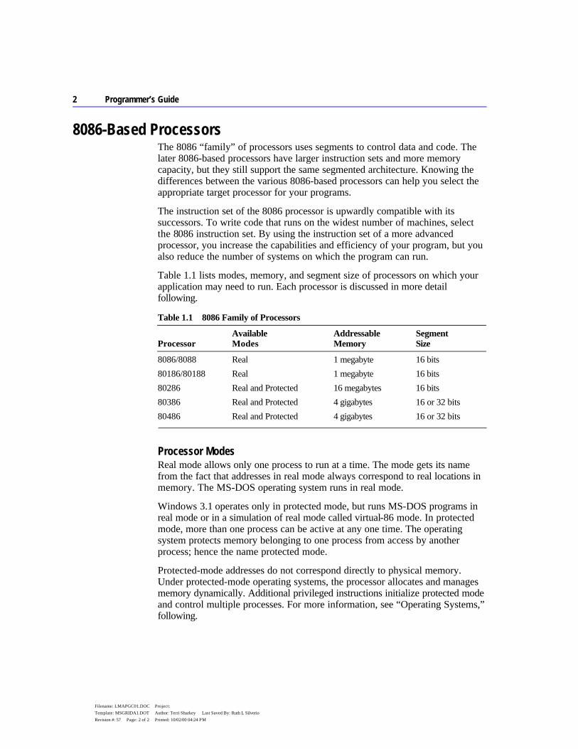
Table 1.1 lists modes, memory, and segment size of processors on which your application may need to run. Each processor is discussed in more detail following.
Table 1.1 8086 Family of Processors
Processor
Available Modes
Addressable Memory
Segment Size
8086/8088 Real 1 megabyte 16 bits 80186/80188 Real 1 megabyte 16 bits 80286 Real and Protected 16 megabytes 16 bits 80386 Real and Protected 4 gigabytes 16 or 32 bits 80486 Real and Protected 4 gigabytes 16 or 32 bits
Processor Modes Real mode allows only one process to run at a time. The mode gets its name from the fact that addresses in real mode always correspond to real locations in memory. The MS-DOS operating system runs in real mode.
Windows 3.1 operates only in protected mode, but runs MS-DOS programs in real mode or in a simulation of real mode called virtual-86 mode. In protected mode, more than one process can be active at any one time. The operating system protects memory belonging to one process from access by another process; hence the name protected mode.
Protected-mode addresses do not correspond directly to physical memory. Under protected-mode operating systems, the processor allocates and manages memory dynamically. Additional privileged instructions initialize protected mode and control multiple processes. For more information, see “Operating Systems,” following.
Chapter 1 Understanding Global Concepts 3
Filename: LMAPGC01.DOC Project: Template: MSGRIDA1.DOT Author: Terri Sharkey Last Saved By: Ruth L Silverio Revision #: 57 Page: 3 of 3 Printed: 10/02/00 04:24 PM
8086 and 8088 The 8086 is faster than the 8088 because of its 16-bit data bus; the 8088 has only an 8-bit data bus. The 16-bit data bus allows you to use EVEN and ALIGN on an 8086 processor to word-align data and thus improve data-handling efficiency. Memory addresses on the 8086 and 8088 refer to actual physical addresses.
80186 and 80188 These two processors are identical to the 8086 and 8088 except that new instructions have been added and several old instructions have been optimized. These processors run significantly faster than the 8086.
80286 The 80286 processor adds some instructions to control protected mode, and it runs faster. It also provides protected mode services, allowing the operating system to run multiple processes at the same time. The 80286 is the minimum for running Windows 3.1 and 16-bit versions of OS/2 ®.
80386 Unlike its predecessors, the 80386 processor can handle both 16-bit and 32-bit data. It supports the entire instruction set of the 80286, and adds several new instructions as well. Software written for the 80286 runs unchanged on the 80386, but is faster because the chip operates at higher speeds.
The 80386 implements many new hardware-level features, including paged memory, multiple virtual 8086 processes, addressing of up to 4 gigabytes of memory, and specialized debugging registers. Thirty-two–bit operating systems such as Windows NT and OS/2 2.0 can run only on an 80386 or higher processor.
80486 The 80486 processor is an enhanced version of the 80386, with instruction “pipelining” that executes many instructions two to three times faster. The chip incorporates both a math coprocessor and an 8K (kilobyte) memory cache. (The math coprocessor is disabled on a variation of the chip called the 80486SX.) The 80486 includes new instructions and is fully compatible with 80386 software.
8087, 80287, and 80387 These math coprocessors work concurrently with the 8086 family of processors. Performing floating-point calculations with math coprocessors is up to 100 times faster than emulating the calculations with integer instructions. Although there are technical and performance differences among the three coprocessors, the main difference to the applications programmer is that the 80287 and 80387 can
4 Programmer’s Guide
Filename: LMAPGC01.DOC Project: Template: MSGRIDA1.DOT Author: Terri Sharkey Last Saved By: Ruth L Silverio Revision #: 57 Page: 4 of 4 Printed: 10/02/00 04:24 PM
operate in protected mode. The 80387 also has several new instructions. The 80486 does not use any of these coprocessors; its floating-point processor is built in and is functionally equivalent to the 80387.
Operating Systems With MASM, you can create programs that run under MS-DOS, Windows, or Windows NT — or all three, in some cases. For example, ML.EXE can produce executable files that run in any of the target environments, regardless of the programmer’s environment. For information on building programs for different environments, see “Building and Running Programs” in Help for PWB.
MS-DOS and Windows 3.1 provide different processing modes. MS-DOS runs in the single-process real mode. Windows 3.1 operates in protected mode, allowing multiple processes to run simultaneously.
Although Windows requires another operating system for loading and file services, it provides many functions normally associated with an operating system. When an application requests an MS-DOS service, Windows often provides the service without invoking MS-DOS. For consistency, this book refers to Windows as an operating system.
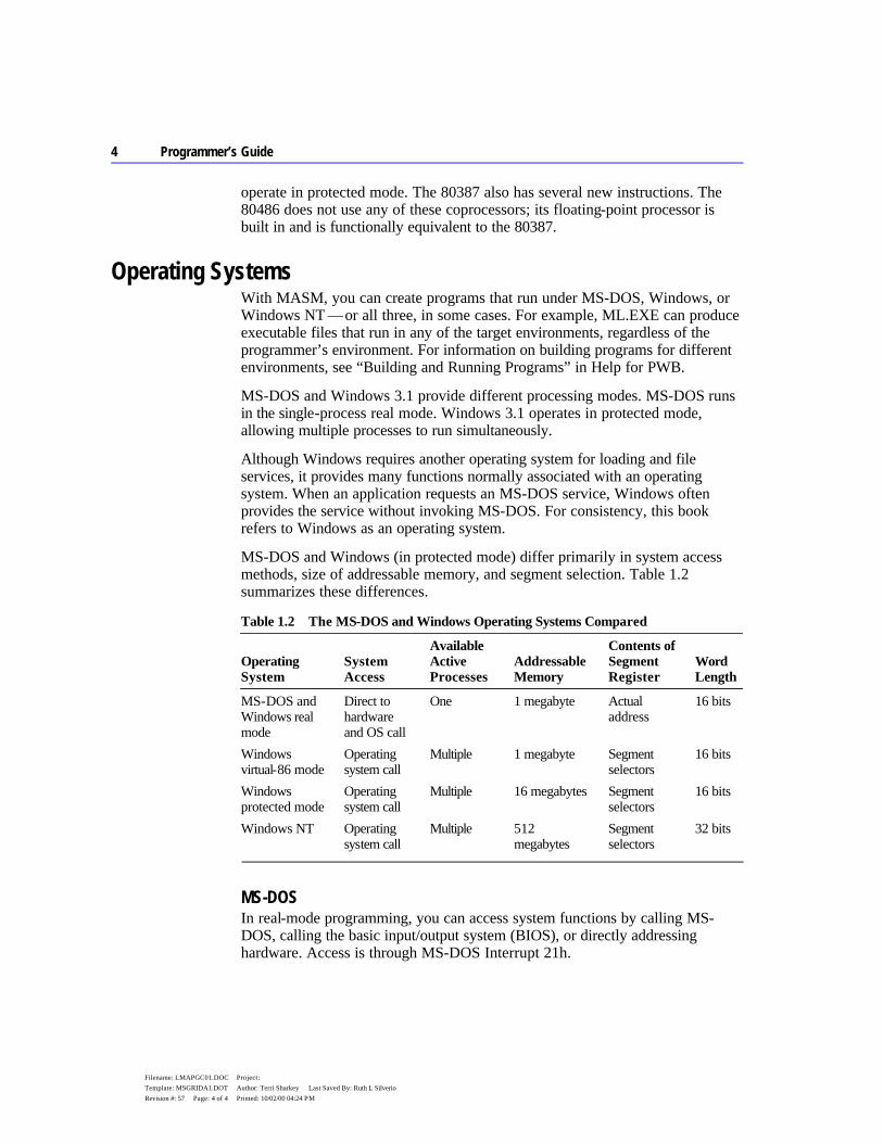
MS-DOS and Windows (in protected mode) differ primarily in system access methods, size of addressable memory, and segment selection. Table 1.2 summarizes these differences.
Table 1.2 The MS-DOS and Windows Operating Systems Compared
Operating System
System Access
Available Active Processes
Addressable Memory
Contents of Segment Register
Word Length
MS-DOS and Windows real mode
Direct to hardware and OS call
One 1 megabyte Actual address
16 bits
Windows virtual-86 mode
Operating system call
Multiple 1 megabyte Segment selectors
16 bits
Windows protected mode
Operating system call
Multiple 16 megabytes Segment selectors
16 bits
Windows NT Operating system call
Multiple 512 megabytes
Segment selectors
32 bits
MS-DOS In real-mode programming, you can access system functions by calling MS-DOS, calling the basic input/output system (BIOS), or directly addressing hardware. Access is through MS-DOS Interrupt 21h.
Chapter 1 Understanding Global Concepts 5
Filename: LMAPGC01.DOC Project: Template: MSGRIDA1.DOT Author: Terri Sharkey Last Saved By: Ruth L Silverio Revision #: 57 Page: 5 of 5 Printed: 10/02/00 04:24 PM
Windows As you can see in Table 1.2, protected mode allows for much larger data structures than real mode, since addressable memory extends to 16 megabytes. In protected mode, segment registers contain selector values rather than actual segment addresses. These selectors cannot be calculated by the program; they must be obtained by calling the operating system. Programs that attempt to calculate segment values or to address memory directly do not work in protected mode.
Protected mode uses privilege levels to maintain system integrity and security. Programs cannot access data or code that is in a higher privilege level. Some instructions that directly access ports or affect interrupts (such as CLI, STI, IN, and OUT) are available at privilege levels normally used only by systems programmers.
Windows protected mode provides each application with up to 16 megabytes of “virtual memory,” even on computers that have less physical memory. The term virtual memory refers to the operating system’s ability to use a swap area on the hard disk as an extension of real memory. When a Windows application requires more memory than is available, Windows writes sections of occupied memory to the swap area, thus freeing those sections for other use. It then provides the memory to the application that made the memory request. When the owner of the swapped data regains control, Windows restores the data from disk to memory, swapping out other memory if required.
Windows NT Windows NT uses the so-called “flat model” of 80386/486 processors. This model places the processor’s entire address space within one 32-bit segment. The section “Defining Basic Attributes with .MODEL” in Chapter 2 explains how to use the flat model. In flat model, your program can (in theory) access up to 4 gigabytes of virtual memory. Since code, data, and stack reside in the same segment, each segment register can hold the same value, which need never change.
Segmented Architecture The 8086 family of processors employs a segmented architecture — that is, each address is represented as a segment and an offset. Segmented addresses affect many aspects of assembly-language programming, especially addresses and pointers.
Segmented architecture was originally designed to enable a 16-bit processor to access an address space larger than 64K. (The section “Segmented Addressing,” later in this chapter, explains how the processor uses both the segment and offset to create addresses larger than 64K.) MS-DOS is an example of an operating system that uses segmented architecture on a 16-bit processor.

6 Programmer’s Guide
Filename: LMAPGC01.DOC Project: Template: MSGRIDA1.DOT Author: Terri Sharkey Last Saved By: Ruth L Silverio Revision #: 57 Page: 6 of 6 Printed: 10/02/00 04:24 PM
With the advent of protected-mode processors such as the 80286, segmented architecture gained a second purpose. Segments can separate different blocks of code and data to protect them from undesirable interactions. Windows takes advantage of the protection features of the 16-bit segments on the 80286.
Segmented architecture went through another significant change with the release of 32-bit processors, starting with the 80386. These processors are compatible with the older 16-bit processors, but allow flat model 32-bit offset values up to 4 gigabytes. Offset values of this magnitude remove the memory limitations of segmented architecture. The Windows NT operating system uses 32-bit addressing.
Segment Protection Segmented architecture is an important part of the Windows memory-protection scheme. In a “multitasking” operating system in which numerous programs can run simultaneously, programs cannot access the code and data of another process without permission.
In MS-DOS, the data and code segments are usually allocated adjacent to each other, as shown in Figure 1.1. In Windows, the data and code segments can be anywhere in memory. The programmer knows nothing about, and has no control over, their location. The operating system can even move the segments to a new memory location or to disk while the program is running.
Figure 1.1 Segment Allocation
Segment protection makes software development easier and more reliable in Windows than in MS-DOS, because Windows immediately detects illegal
Chapter 1 Understanding Global Concepts 7
Filename: LMAPGC01.DOC Project: Template: MSGRIDA1.DOT Author: Terri Sharkey Last Saved By: Ruth L Silverio Revision #: 57 Page: 7 of 7 Printed: 10/02/00 04:24 PM
memory accesses. The operating system intercepts illegal memory accesses, terminates the program, and displays a message. This makes it easier for you to track down and fix the bug.
Because it runs in real mode, MS-DOS contains no mechanism for detecting an improper memory access. A program that overwrites data not belonging to it may continue to run and even terminate correctly. The error may not surface until later, when MS-DOS or another program reads the corrupted memory.
Segmented Addressing Segmented addressing refers to the internal mechanism that combines a segment value and an offset value to form a complete memory address. The two parts of an address are represented as
segment:offset
The segment portion always consists of a 16-bit value. The offset portion is a 16-bit value in 16-bit mode or a 32-bit value in 32-bit mode.
In real mode, the segment value is a physical address that has an arithmetic relationship to the offset value. The segment and offset together create a 20-bit physical address (explained in the next section). Although 20-bit addresses can access up to 1 megabyte of memory, the BIOS and operating system on International Standard Architecture (IBM PC/AT and compatible) computers use part of this memory, leaving the remainder available for programs.
Segment Arithmetic Manipulating segment and offset addresses directly in real-mode programming is called “segment arithmetic.” Programs that perform segment arithmetic are not portable to protected-mode operating systems, in which addresses do not correspond to a known segment and offset.
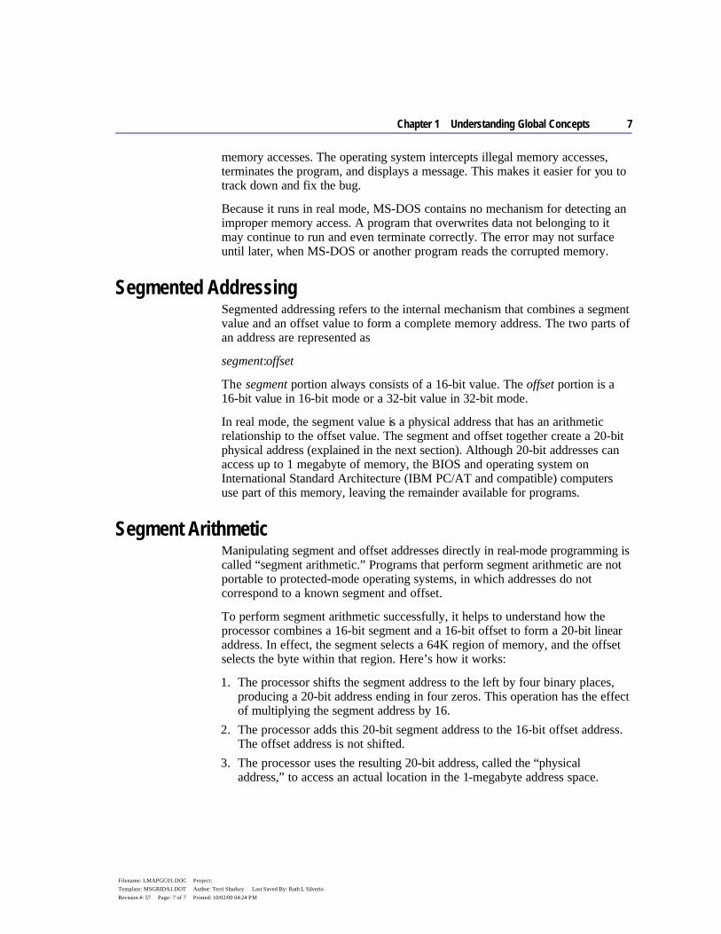
To perform segment arithmetic successfully, it helps to understand how the processor combines a 16-bit segment and a 16-bit offset to form a 20-bit linear address. In effect, the segment selects a 64K region of memory, and the offset selects the byte within that region. Here’s how it works:
1. The processor shifts the segment address to the left by four binary places, producing a 20-bit address ending in four zeros. This operation has the effect of multiplying the segment address by 16.
2. The processor adds this 20-bit segment address to the 16-bit offset address. The offset address is not shifted.
3. The processor uses the resulting 20-bit address, called the “physical address,” to access an actual location in the 1-megabyte address space.
8 Programmer’s Guide
Filename: LMAPGC01.DOC Project: Template: MSGRIDA1.DOT Author: Terri Sharkey Last Saved By: Ruth L Silverio Revision #: 57 Page: 8 of 8 Printed: 10/02/00 04:24 PM
Figure 1.2 illustrates this process.
Figure 1.2 Calculating Physical Addresses
A 20-bit physical address may actually be specified by 4,096 equivalent segment:offset addresses. For example, the addresses 0000:F800, 0F00:0800, and 0F80:0000 all refer to the same physical address 0F800.
Language Components of MASM Programming with MASM requires that you understand the MASM concepts of reserved words, identifiers, predefined symbols, constants, expressions, operators, data types, registers, and statements. This section defines important terms and provides lists that summarize these topics. For detailed information, see Help or the Reference.
Reserved Words A reserved word has a special meaning fixed by the language. You can use it only under certain conditions. Reserved words in MASM include:
u Instructions, which correspond to operations the processor can execute. u Directives, which give commands to the assembler. u Attributes, which provide a value for a field, such as segment alignment. u Operators, which are used in expressions.
Chapter 1 Understanding Global Concepts 9
Filename: LMAPGC01.DOC Project: Template: MSGRIDA1.DOT Author: Terri Sharkey Last Saved By: Ruth L Silverio Revision #: 57 Page: 9 of 9 Printed: 10/02/00 04:24 PM
u Predefined symbols, which return information to your program.
MASM reserved words are not case sensitive except for predefined symbols (see “Predefined Symbols,” later in this chapter).
The assembler generates an error if you use a reserved word as a variable, code label, or other identifier within your source code. However, if you need to use a reserved word for another purpose, the OPTION NOKEYWORD directive can selectively disable a word’s status as a reserved word.
For example, to remove the STR instruction, the MASK operator, and the NAME directive from the set of words MASM recognizes as reserved, use this statement in the code segment of your program before the first reference to STR, MASK, or NAME:
OPTION NOKEYWORD:<STR MASK NAME>
The section “Using the OPTION Directive,” later in this chapter, discusses the OPTION directive. Appendix D provides a complete list of MASM reserved words.
With the /Zm command-line option or OPTION M510 in effect, MASM does not reserve any operators or instructions that do not apply to the current CPU mode. For example, you can use the symbol ENTER when assembling under the default CPU mode but not under .286 mode, since the 80186/486 processors recognize ENTER as an instruction. The USE32, FLAT, FAR32, and NEAR32 segment types and the 80386/486 register names are not keywords with processors other than the 80386/486.
Identifiers An identifier is a name that you invent and attach to a definition. Identifiers can be symbols representing variables, constants, procedure names, code labels, segment names, and user-defined data types such as structures, unions, records, and types defined with TYPEDEF. Identifiers longer than 247 characters generate an error.
Certain restrictions limit the names you can use for identifiers. Follow these rules to define a name for an identifier:
u The first character of the identifier can be an alphabetic character (A–Z) or any of these four characters: @ _ $ ?
u The other characters in the identifier can be any of the characters listed above or a decimal digit (0–9).
Avoid starting an identifier with the at sign (@), because MASM 6.1 predefines some special symbols starting with @ (see “Predefined Symbols,” following).
10 Programmer’s Guide
Filename: LMAPGC01.DOC Project: Template: MSGRIDA1.DOT Author: Terri Sharkey Last Saved By: Ruth L Silverio Revision #: 57 Page: 10 of 10 Printed: 10/02/00 04:24 PM
Beginning an identifier with @ may also cause conflicts with future versions of the Macro Assembler.
The symbol — and thus the identifier — is visible as long as it remains within scope. (For more information about visibility and scope, see “Sharing Symbols with Include Files” in Chapter 8.)
Predefined Symbols The assembler includes a number of predefined symbols (also called predefined equates). You can use these symbol names at any point in your code to represent the equate value. For example, the predefined equate @FileName represents the base name of the current file. If the current source file is TASK.ASM, the value of @FileName is TASK. The MASM predefined symbols are listed according to the kinds of information they provide. Case is important only if the /Cp option is used. (For additional details, see Help on ML command-line options.)
The predefined symbols for segment information include:
Symbol Description
@code Returns the name of the code segment. @CodeSize Returns an integer representing the default code distance. @CurSeg Returns the name of the current segment. @data Expands to DGROUP. @DataSize Returns an integer representing the default data distance. @fardata Returns the name of the segment defined by the .FARDATA directive. @fardata? Returns the name of the segment defined by the .FARDATA? directive. @Model Returns the selected memory model. @stack Expands to DGROUP for near stacks or STACK for far stacks. (See
“Creating a Stack” in Chapter 2.) @WordSize Provides the size attribute of the current segment.
The predefined symbols for environment information include:
Symbol Description
@Cpu Contains a bit mask specifying the processor mode. @Environ Returns values of environment variables during assembly. @Interface Contains information about the language parameters. @Version Represents the text equivalent of the MASM version number. In MASM 6.1,
this expands to 610.
Chapter 1 Understanding Global Concepts 11
Filename: LMAPGC01.DOC Project: Template: MSGRIDA1.DOT Author: Terri Sharkey Last Saved By: Ruth L Silverio Revision #: 57 Page: 11 of 11 Printed: 10/02/00 04:24 PM
The predefined symbols for date and time information include:
Symbol Description
@Date Supplies the current system date during assembly. @Time Supplies the current system time during assembly.
The predefined symbols for file information include:
Symbol Description
@FileCur Names the current file (base and suffix). @FileName Names the base name of the main file being assembled as it appears on the
command line. @Line Gives the source line number in the current file.
The predefined symbols for macro string manipulation include:
Symbol Description
@CatStr Returns concatenation of two strings. @InStr Returns the starting position of a string within another string. @SizeStr Returns the length of a given string. @SubStr Returns substring from a given string.
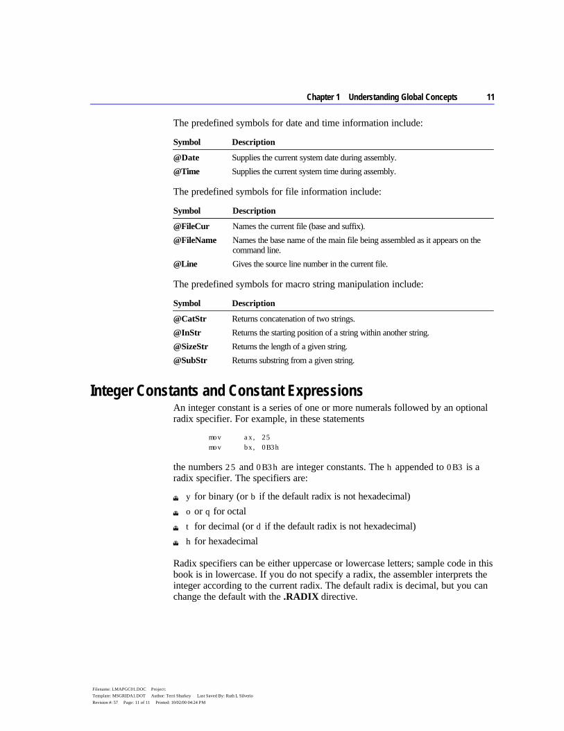
Integer Constants and Constant Expressions An integer constant is a series of one or more numerals followed by an optional radix specifier. For example, in these statements
mov ax, 25 mov bx, 0B3h
the numbers 25 and 0B3h are integer constants. The h appended to 0B3 is a radix specifier. The specifiers are:
u y for binary (or b if the default radix is not hexadecimal) u o or q for octal u t for decimal (or d if the default radix is not hexadecimal) u h for hexadecimal
Radix specifiers can be either uppercase or lowercase letters; sample code in this book is in lowercase. If you do not specify a radix, the assembler interprets the integer according to the current radix. The default radix is decimal, but you can change the default with the .RADIX directive.

12 Programmer’s Guide
Filename: LMAPGC01.DOC Project: Template: MSGRIDA1.DOT Author: Terri Sharkey Last Saved By: Ruth L Silverio Revision #: 57 Page: 12 of 12 Printed: 10/02/00 04:24 PM
Hexadecimal numbers must always start with a decimal digit (0–9). If necessary, add a leading zero to distinguish between symbols and hexadecimal numbers that start with a letter. For example, MASM interprets ABCh as an identifier. The hexadecimal digits A through F can be either uppercase or lowercase letters. Sample code in this book is in uppercase letters.
Constant expressions contain integer constants and (optionally) operators such as shift, logical, and arithmetic operators. The assembler evaluates constant expressions at assembly time. (In addition to constants, expressions can contain labels, types, registers, and their attributes.) Constant expressions do not change value during program execution.
Symbolic Integer Constants You can define symbolic integer constants with either of the data assignment directives, EQU or the equal sign (=). These directives assign values to symbols during assembly, not during program execution. Symbolic constants are used to assign names to constant values. You can use a symbol with an assigned value in place of an immediate operand. For example, instead of referring in your code to keyboard scan codes with numbers such as 30 or 48, you can create more recognizable symbols:
SCAN_A EQU 30 SCAN_B EQU 48
then use the appropriate symbol in your program rather than the number. Using symbolic constants instead of undescriptive numbers makes your code more readable and easier to maintain. The assembler does not allocate data storage when you use either EQU or =. It simply replaces each occurrence of the symbol with the value of the expression.
The directives EQU and = have slightly different purposes. Integers defined with the = directive can be redefined with another value in your source code, but those defined with EQU cannot. Once you’ve defined a symbolic constant with the EQU directive, attempting to redefine it generates an error. The syntax is:
symbol EQU expression
The symbol is a unique name of your choice, except for words reserved by MASM. The expression can be an integer, a constant expression, a one- or two-character string constant (four-character on the 80386/486), or an expression that evaluates to an address. Symbolic constants let you change a constant value used throughout your source code by merely altering expression in the definition. This removes the potential for error and saves you the inconvenience of having to find and replace each occurrence of the constant in your program.

Chapter 1 Understanding Global Concepts 13
Filename: LMAPGC01.DOC Project: Template: MSGRIDA1.DOT Author: Terri Sharkey Last Saved By: Ruth L Silverio Revision #: 57 Page: 13 of 13 Printed: 10/02/00 04:24 PM
The following example shows the correct use of EQU to define symbolic integers.
column EQU 80 ; Constant - 80 row EQU 25 ; Constant - 25 screen EQU column * row ; Constant - 2000 line EQU row ; Constant - 25 .DATA .CODE . . . mov cx, column mov bx, line
The value of a symbol defined with the = directive can be different at different places in the source code. However, a constant value is assigned during assembly for each use, and that value does not change at run time.
The syntax for the = directive is:
symbol = expression
Size of Constants The default word size for MASM 6.1 expressions is 32 bits. This behavior can be modified using OPTION EXPR16 or OPTION M510. Both of these options set the expression word size to 16 bits, but OPTION M510 affects other assembler behavior as well (see Appendix A).
It is illegal to change the expression word size once it has been set with OPTION M510, OPTION EXPR16, or OPTION EXPR32. However, you can repeat the same directive in your source code as often as you wish. You can place the same directive in every include file, for example.
Operators Operators are used in expressions. The value of the expression is determined at assembly time and does not change when the program runs.
Operators should not be confused with processor instructions. The reserved word ADD is an instruction; the plus sign (+) is an operator. For example, Amount+2 illustrates a valid use of the plus operator (+). It tells the assembler to add 2 to the constant value Amount, which might be a value or an address. Contrast this operation, which occurs at assembly time, with the processor’s ADD instruction. ADD tells the processor at run time to add two numbers and store the result.
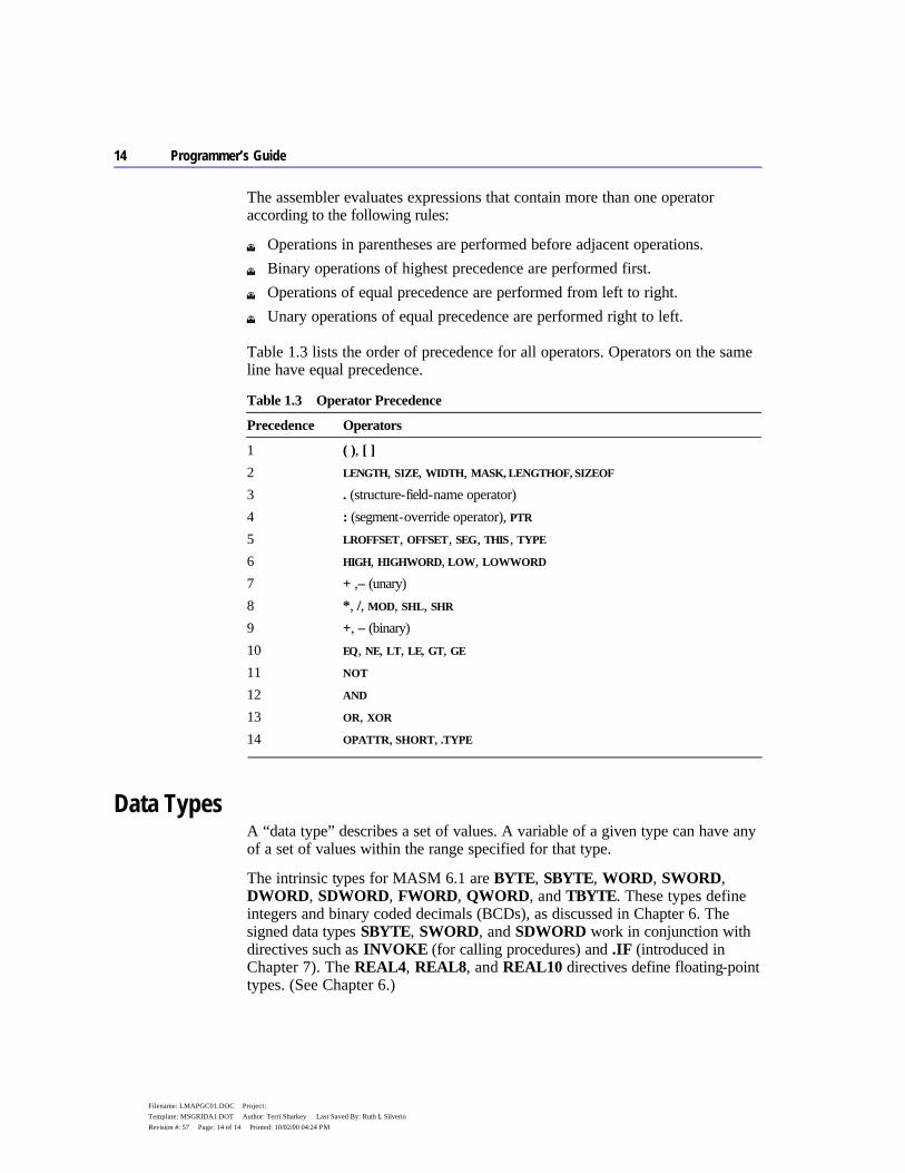
14 Programmer’s Guide
Filename: LMAPGC01.DOC Project: Template: MSGRIDA1.DOT Author: Terri Sharkey Last Saved By: Ruth L Silverio Revision #: 57 Page: 14 of 14 Printed: 10/02/00 04:24 PM
The assembler evaluates expressions that contain more than one operator according to the following rules:
u Operations in parentheses are performed before adjacent operations. u Binary operations of highest precedence are performed first. u Operations of equal precedence are performed from left to right. u Unary operations of equal precedence are performed right to left.
Table 1.3 lists the order of precedence for all operators. Operators on the same line have equal precedence.
Table 1.3 Operator Precedence
Precedence Operators
1 ( ), [ ] 2 LENGTH, SIZE, WIDTH, MASK, LENGTHOF, SIZEOF 3 . (structure-field-name operator) 4 : (segment-override operator), PTR 5 LROFFSET, OFFSET, SEG, THIS, TYPE 6 HIGH, HIGHWORD, LOW, LOWWORD 7 + ,– (unary) 8 *, /, MOD, SHL, SHR 9 +, – (binary) 10 EQ, NE, LT, LE, GT, GE 11 NOT 12 AND 13 OR, XOR 14 OPATTR, SHORT, .TYPE
Data Types A “data type” describes a set of values. A variable of a given type can have any of a set of values within the range specified for that type.
The intrinsic types for MASM 6.1 are BYTE, SBYTE, WORD, SWORD, DWORD, SDWORD, FWORD, QWORD, and TBYTE. These types define integers and binary coded decimals (BCDs), as discussed in Chapter 6. The signed data types SBYTE, SWORD, and SDWORD work in conjunction with directives such as INVOKE (for calling procedures) and .IF (introduced in Chapter 7). The REAL4, REAL8, and REAL10 directives define floating-point types. (See Chapter 6.)

Chapter 1 Understanding Global Concepts 15
Filename: LMAPGC01.DOC Project: Template: MSGRIDA1.DOT Author: Terri Sharkey Last Saved By: Ruth L Silverio Revision #: 57 Page: 15 of 15 Printed: 10/02/00 04:24 PM
Versions of MASM prior to 6.0 had separate directives for types and initializers. For example, BYTE is a type and DB is the corresponding initializer. The distinction does not apply in MASM 6.1. You can use any type (intrinsic or user-defined) as an initializer.
MASM does not have specific types for arrays and strings. However, you can treat a sequence of data units as arrays, and character or byte sequences as strings. (See “Arrays and Strings” in Chapter 5.)
Types can also have attributes such as langtype and distance (NEAR and FAR). For information on these attributes, see “Declaring Parameters with the PROC Directive” in Chapter 7.
You can also define your own types with STRUCT, UNION, and RECORD. The types have fields that contain string or numeric data, or records that contain bits. These data types are similar to the user-defined data types in high-level languages such as C, Pascal, and FORTRAN. (See Chapter 5, “Defining and Using Complex Data Types.”)
You can define new types, including pointer types, with the TYPEDEF directive. TYPEDEF assigns a qualifiedtype (explained in the following) to a typename of your choice. This lets you build new types with descriptive names of your choosing, making your programs more readable. For example, the following statement makes the symbol CHAR a synonym for the intrinsic type BYTE:
CHAR TYPEDEF BYTE
The qualifiedtype is any type or pointer to a type of the form:
[[distance]] PTR [[qualifiedtype]]
where distance is NEAR, FAR, or any distance modifier. (For more information on distance, see “Declaring Parameters with the PROC Directive” in Chapter 7.)
The qualifiedtype can also be any type previously defined with TYPEDEF. For example, if you use TYPEDEF to create an alias for BYTE — say, CHAR as in the preceding example — you can use CHAR as a qualifiedtype when defining the pointer type PCHAR, like this:
CHAR TYPEDEF BYTE PCHAR TYPEDEF PTR CHAR
The typename CHAR in the first line becomes a qualifiedtype in the second line. Use of the TYPEDEF directive to define pointers is explained in “Accessing Data with Pointers and Addresses” in Chapter 3.
16 Programmer’s Guide
Filename: LMAPGC01.DOC Project: Template: MSGRIDA1.DOT Author: Terri Sharkey Last Saved By: Ruth L Silverio Revision #: 57 Page: 16 of 16 Printed: 10/02/00 04:24 PM
Since distance and qualifiedtype are optional syntax elements, you can use variables of type PTR or FAR PTR. You can also define procedure prototypes with qualifiedtype. For more information about procedure prototypes, see “Declaring Procedure Prototypes” in Chapter 7.
These rules govern the use of qualifiedtype:
u The only component of a qualifiedtype definition that can be forward- referenced is a structure or union type identifier.
u If you do not specify distance, the assembler assumes a distance that corresponds to the memory model. The assumed distance is NEAR for tiny, small, and medium models, and FAR for other models.
u If you do not specify a memory model with .MODEL, the assembler assumes SMALL model (and therefore NEAR pointers).
You can use a qualifiedtype in seven places:
Use Example
In procedure arguments proc1 PROC pMsg:PTR BYTE In prototype arguments proc2 PROTO pMsg:FAR PTR WORD With local variables declared inside procedures
LOCAL pMsg:PTR
With the LABEL directive TempMsg LABEL PTR WORD With the EXTERN and EXTERNDEF directives
EXTERN pMsg:FAR PTR BYTE EXTERNDEF MyProc:PROTO
With the COMM directive COMM var1:WORD:3 With the TYPEDEF directive PBYTE TYPEDEF PTR BYTE
PFUNC TYPEDEF PROTO MyProc
“Defining Pointer Types with TYPEDEF” in Chapter 3 shows ways to write a TYPEDEF type for a qualifiedtype. Attributes such as NEAR and FAR can also apply to a qualifiedtype.
You can determine an accurate definition for TYPEDEF and qualifiedtype from the BNF grammar definitions given in Appendix B. The BNF grammar defines each component of the syntax for any directive, showing the recursive properties of components such as qualifiedtype.
Registers The 8086 family of processors have the same base set of 16-bit registers. Each processor can treat certain registers as two separate 8-bit registers. The 80386/486 processors have extended 32-bit registers. To maintain compatibility
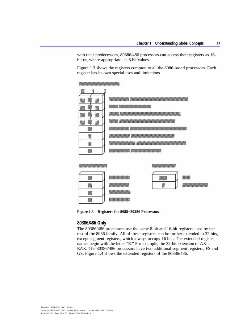
Chapter 1 Understanding Global Concepts 17
Filename: LMAPGC01.DOC Project: Template: MSGRIDA1.DOT Author: Terri Sharkey Last Saved By: Ruth L Silverio Revision #: 57 Page: 17 of 17 Printed: 10/02/00 04:24 PM
with their predecessors, 80386/486 processors can access their registers as 16-bit or, where appropriate, as 8-bit values.
Figure 1.3 shows the registers common to all the 8086-based processors. Each register has its own special uses and limitations.
Figure 1.3 Registers for 8088 – 80286 Processors
80386/486 Only The 80386/486 processors use the same 8-bit and 16-bit registers used by the rest of the 8086 family. All of these registers can be further extended to 32 bits, except segment registers, which always occupy 16 bits. The extended register names begin with the letter “E.” For example, the 32-bit extension of AX is EAX. The 80386/486 processors have two additional segment registers, FS and GS. Figure 1.4 shows the extended registers of the 80386/486.
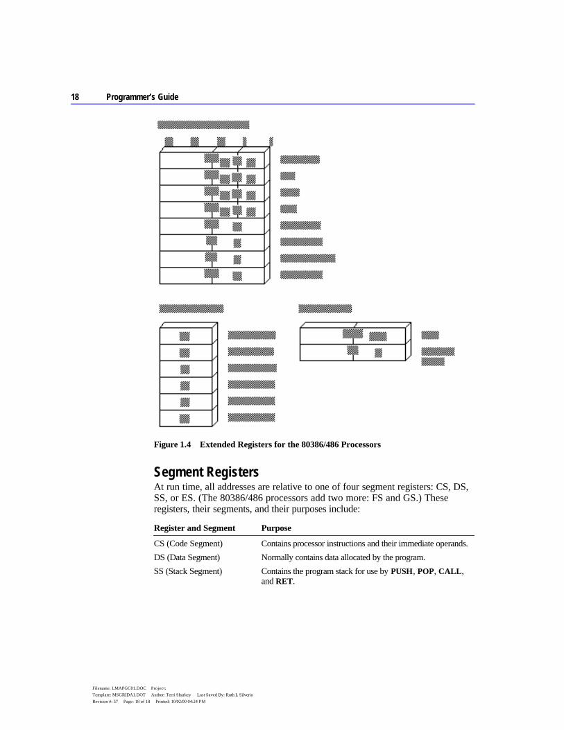
18 Programmer’s Guide
Filename: LMAPGC01.DOC Project: Template: MSGRIDA1.DOT Author: Terri Sharkey Last Saved By: Ruth L Silverio Revision #: 57 Page: 18 of 18 Printed: 10/02/00 04:24 PM
Figure 1.4 Extended Registers for the 80386/486 Processors
Segment Registers At run time, all addresses are relative to one of four segment registers: CS, DS, SS, or ES. (The 80386/486 processors add two more: FS and GS.) These registers, their segments, and their purposes include:
Register and Segment Purpose
CS (Code Segment) Contains processor instructions and their immediate operands. DS (Data Segment) Normally contains data allocated by the program. SS (Stack Segment) Contains the program stack for use by PUSH, POP, CALL,
and RET.
Chapter 1 Understanding Global Concepts 19
Filename: LMAPGC01.DOC Project: Template: MSGRIDA1.DOT Author: Terri Sharkey Last Saved By: Ruth L Silverio Revision #: 57 Page: 19 of 19 Printed: 10/02/00 04:24 PM
Register and Segment Purpose
ES (Extra Segment) References secondary data segment. Used by string instructions.
FS, GS Provides extra segments on the 80386/486.
General-Purpose Registers The AX, DX, CX, BX, BP, DI, and SI registers are 16-bit general-purpose registers, used for temporary data storage. Since the processor accesses registers more quickly than it accesses memory, you can make your programs run faster by keeping the most-frequently used data in registers.
The 8086-based processors do not perform memory-to-memory operations. For example, the processor cannot directly copy a variable from one location in memory to another. You must first copy from memory to a register, then from the register to the new memory location. Similarly, to add two variables in memory, you must first copy one variable to a register, then add the contents of the register to the other variable in memory.
The processor can access four of the general registers — AX, DX, CX, and BX — either as two 8-bit registers or as a single 16-bit register. The AH, DH, CH, and BH registers represent the high-order 8 bits of the corresponding registers. Similarly, AL, DL, CL, and BL represent the low-order 8 bits of the registers.
The 80386/486 processors can extend all the general registers to 32 bits, though as Figure 1.4 shows, you cannot treat the upper 16 bits as a separate register as you can the lower 16 bits. To use EAX as an example, you can directly reference the low byte as AL, the next lowest byte as AH, and the low word as AX. To access the high word of EAX, however, you must first shift the upper 16 bits into the lower 16 bits.
Special-Purpose Registers The 8086 family of processors has two additional registers, SP and IP, whose values are changed automatically by the processor.
SP (Stack Pointer) The SP register points to the current location within the stack segment. Pushing a value onto the stack decreases the value of SP by two; popping from the stack increases the value of SP by two. Thirty-two–bit operands on 80386/486 processors increase or decrease SP by four instead of two. The CALL and INT instructions store the return address on the stack and reduce SP accordingly. Return instructions retrieve the stored address from the stack and reset SP to its value before the call. SP can also be adjusted with instructions such as ADD. The program stack is described in detail in Chapter 3.
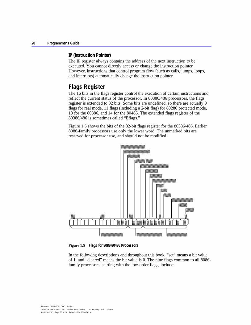
20 Programmer’s Guide
Filename: LMAPGC01.DOC Project: Template: MSGRIDA1.DOT Author: Terri Sharkey Last Saved By: Ruth L Silverio Revision #: 57 Page: 20 of 20 Printed: 10/02/00 04:24 PM
IP (Instruction Pointer) The IP register always contains the address of the next instruction to be executed. You cannot directly access or change the instruction pointer. However, instructions that control program flow (such as calls, jumps, loops, and interrupts) automatically change the instruction pointer.
Flags Register The 16 bits in the flags register control the execution of certain instructions and reflect the current status of the processor. In 80386/486 processors, the flags register is extended to 32 bits. Some bits are undefined, so there are actually 9 flags for real mode, 11 flags (including a 2-bit flag) for 80286 protected mode, 13 for the 80386, and 14 for the 80486. The extended flags register of the 80386/486 is sometimes called “Eflags.”
Figure 1.5 shows the bits of the 32-bit flags register for the 80386/486. Earlier 8086-family processors use only the lower word. The unmarked bits are reserved for processor use, and should not be modified.
Figure 1.5 Flags for 8088-80486 Processors
In the following descriptions and throughout this book, “set” means a bit value of 1, and “cleared” means the bit value is 0. The nine flags common to all 8086-family processors, starting with the low-order flags, include:
Chapter 1 Understanding Global Concepts 21
Filename: LMAPGC01.DOC Project: Template: MSGRIDA1.DOT Author: Terri Sharkey Last Saved By: Ruth L Silverio Revision #: 57 Page: 21 of 21 Printed: 10/02/00 04:24 PM
Flag Description
Carry Set if an operation generates a carry to or a borrow from a destination operand.
Parity Set if the low-order bits of the result of an operation contain an even number of set bits.
Auxiliary Carry Set if an operation generates a carry to or a borrow from the low-order 4 bits of an operand. This flag is used for binary coded decimal (BCD) arithmetic.
Zero Set if the result of an operation is 0. Sign Equal to the high-order bit of the result of an operation (0 is positive, 1 is
negative). Trap If set, the processor generates a single-step interrupt after each
instruction. A debugging program can use this feature to execute a program one instruction at a time.
Interrupt Enable If set, interrupts are recognized and acted on as they are received. The bit can be cleared to turn off interrupt processing temporarily.
Direction If set, string operations process down from high addresses to low addresses. If cleared, string operations process up from low addresses to high addresses.
Overflow Set if the result of an operation is too large or small to fit in the destination operand.
Although all flags serve a purpose, most programs require only the carry, zero, sign, and direction flags.
Statements Statements are the line-by-line components of source files. Each MASM statement specifies an instruction or directive for the assembler. Statements have up to four fields, as shown here:
[[name:]] [[operation]] [[operands]] [[;comment]]
The following list explains each field:
Field Purpose
name Labels the statement, so that instructions elsewhere in the program can refer to the statement by name. The name field can label a variable, type, segment, or code location.
operation Defines the action of the statement. This field contains either an instruction or an assembler directive.
operands Lists one or more items on which the instruction or directive operates. comment Provides a comment for the programmer. Comments are for documentation
only; they are ignored by the assembler.
22 Programmer’s Guide
Filename: LMAPGC01.DOC Project: Template: MSGRIDA1.DOT Author: Terri Sharkey Last Saved By: Ruth L Silverio Revision #: 57 Page: 22 of 22 Printed: 10/02/00 04:24 PM
The following line contains all four fields:
mainlp: mov ax, 7 ; Load AX with the value 7
Here, mainlp is the label, mov is the operation, and ax and 7 are the operands, separated by a comma. The comment follows the semicolon.
All fields are optional, although certain directives and instructions require an entry in the name or operand field. Some instructions and directives place restrictions on the choice of operands. By default, MASM is not case sensitive.
Each field (except the comment field) must be separated from other fields by white-space characters (spaces or tabs). MASM also requires code labels to be followed by a colon, operands to be separated by commas, and comments to be preceded by a semicolon.
A logical line can contain up to 512 characters and occupy one or more physical lines. To extend a logical line into two or more physical lines, put the backslash character (\) as the last non-whitespace character before the comment or end of the line. You can place a comment after the backslash as shown in this example:
.IF (x > 0) \ ; X must be positive && (ax > x) \ ; Result from function must be > x && (cx == 0) ; Check loop counter, too mov dx, 20h .ENDIF
Multiline comments can also be specified with the COMMENT directive. The assembler ignores all text and code between the delimiters or on the same line as the delimiters. This example illustrates the use of COMMENT.
COMMENT ^ The assembler ignores this text ^ mov ax, 1 and this code
The Assembly Process Creating and running an executable file involves four steps:
1. Assembling the source code into an object file 2. Linking the object file with other modules or libraries into an executable
program 3. Loading the program into memory 4. Running the program
Chapter 1 Understanding Global Concepts 23
Filename: LMAPGC01.DOC Project: Template: MSGRIDA1.DOT Author: Terri Sharkey Last Saved By: Ruth L Silverio Revision #: 57 Page: 23 of 23 Printed: 10/02/00 04:24 PM
Once you have written your assembly-language program, MASM provides several options for assembling it. The OPTION directive has several different arguments that let you control the way MASM assembles your programs.
Conditional assembly allows you to create one source file that can generate a variety of programs, depending on the status of various conditional-assembly statements.
Generating and Running Executable Programs This section briefly lists all the actions that take place during each of the assembly steps. You can change the behavior of some of these actions in various ways, such as using macros instead of procedures, or using the OPTION directive or conditional assembly. The other chapters in this book include specific programming methods; this section simply gives you an overview.
Assembling The ML.EXE program does two things to create an executable program. First, it assembles the source code into an intermediate object file. Second, it calls the linker, LINK.EXE, which links the object files and libraries into an executable program.
At assembly time, the assembler:
u Evaluates conditional-assembly directives, assembling if the conditions are true.
u Expands macros and macro functions. u Evaluates constant expressions such as MYFLAG AND 80H, substituting the
calculated value for the expression. u Encodes instructions and nonaddress operands. For example, mov cx, 13
can be encoded at assembly time because the instruction does not access memory.
u Saves memory offsets as offsets from their segments. u Places segments and segment attributes in the object file. u Saves placeholders for offsets and segments (relocatable addresses). u Outputs a listing if requested. u Passes messages (such as INCLUDELIB and .DOSSEG) directly to the
linker.
For information about conditional assembly, see “Conditional Directives” in this chapter; for macros, see Chapter 9. Further details about segments and offsets are included in Chapters 2 and 3. Assembly listings are explained in Appendix C.
24 Programmer’s Guide
Filename: LMAPGC01.DOC Project: Template: MSGRIDA1.DOT Author: Terri Sharkey Last Saved By: Ruth L Silverio Revision #: 57 Page: 24 of 24 Printed: 10/02/00 04:24 PM
Linking Once your source code is assembled, the resulting object file is passed to the linker. At this point, the linker may combine several object files into an executable program. The linker:
u Combines segments according to the instructions in the object files, rearranging the positions of segments that share the same class or group.
u Fills in placeholders for offsets (relocatable addresses). u Writes relocations for segments into the header of .EXE files (but not .COM
files). u Writes the result as an executable program file.
Classes and groups are defined in “Defining Segment Groups” in Chapter 2. Segments and offsets are explained in Chapter 3, “Using Addresses and Pointers.”
Loading After loading the executable file into memory, the operating system:
u Creates the program segment prefix (PSP) header in memory. u Allocates memory for the program, based on the values in the PSP. u Loads the program. u Calculates the correct values for absolute addresses from the relocation table. u Loads the segment registers SS, CS, DS, and ES with values that point to the
proper areas of memory.
For information about segment registers, the instruction pointer (IP), and the stack pointer (SP), see “Registers” earlier in this chapter. For more information on the PSP see Help or an MS-DOS reference.
Running To run your program, MS-DOS jumps to the program’s first instruction. Some program operations, such as resolving indirect memory operands, cannot be handled until the program runs. For a description of indirect references, see “Indirect Operands” in Chapter 7.
Using the OPTION Directive The OPTION directive lets you modify global aspects of the assembly process. With OPTION, you can change command-line options and default arguments. These changes affect only statements that follow the OPTION keyword.
Chapter 1 Understanding Global Concepts 25
Filename: LMAPGC01.DOC Project: Template: MSGRIDA1.DOT Author: Terri Sharkey Last Saved By: Ruth L Silverio Revision #: 57 Page: 25 of 25 Printed: 10/02/00 04:24 PM
For example, you may have MASM code in which the first character of a variable, macro, structure, or field name is a dot (.). Since a leading dot causes MASM 6.1 to generate an error, you can use this statement in your program:
OPTION DOTNAME
This enables the use of the dot for the first character.
Changes made with OPTION override any corresponding command-line option. For example, suppose you compile a module with this command line (which enables M510 compatibility):
ML /Zm TEST.ASM
The assembler disables M510 compatibility options for all code following this statement:
OPTION NOM510
The following lists explain each of the arguments for the OPTION directive. Where appropriate, an underline identifies the default argument. If you wish to place more than one OPTION statement on a line, separate them by commas.
Options for M510 compatibility include:
Argument Description
CASEMAP: maptype CASEMAP:NONE (or /Cx) causes internal symbol recognition to be case sensitive and causes the case of identifiers in the .OBJ file to be the same as specified in the EXTERNDEF, PUBLIC, or COMM statement. The default is CASEMAP:NOTPUBLIC (or /Cp). It specifies case insensitivity for internal symbol recognition and the same behavior as CASEMAP:NONE for case of identifiers in .OBJ files. CASEMAP:ALL (/Cu) specifies case insensitivity for identifiers and converts all identifier names to uppercase.
DOTNAME | NODOTNAME Enables the use of the dot (.) as the leading character in variable, macro, structure, union, and member names.
M510 | NOM510 Sets all features to be compatible with MASM version 5.1, disabling the SCOPED argument and enabling OLDMACROS, DOTNAME, and, OLDSTRUCTS. OPTION M510 conditionally sets other arguments for the OPTION directive. For more information on using OPTION M510, see Appendix A.
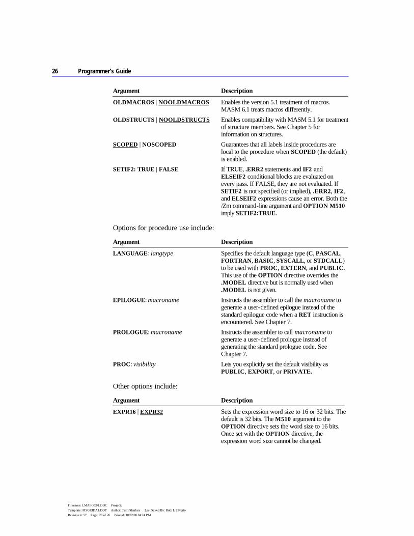
26 Programmer’s Guide
Filename: LMAPGC01.DOC Project: Template: MSGRIDA1.DOT Author: Terri Sharkey Last Saved By: Ruth L Silverio Revision #: 57 Page: 26 of 26 Printed: 10/02/00 04:24 PM
Argument Description
OLDMACROS | NOOLDMACROS Enables the version 5.1 treatment of macros. MASM 6.1 treats macros differently.
OLDSTRUCTS | NOOLDSTRUCTS Enables compatibility with MASM 5.1 for treatment of structure members. See Chapter 5 for information on structures.
SCOPED | NOSCOPED Guarantees that all labels inside procedures are local to the procedure when SCOPED (the default) is enabled.
SETIF2: TRUE | FALSE If TRUE, .ERR2 statements and IF2 and ELSEIF2 conditional blocks are evaluated on every pass. If FALSE, they are not evaluated. If SETIF2 is not specified (or implied), .ERR2, IF2, and ELSEIF2 expressions cause an error. Both the /Zm command-line argument and OPTION M510 imply SETIF2:TRUE.
Options for procedure use include:
Argument Description
LANGUAGE: langtype Specifies the default language type (C, PASCAL, FORTRAN, BASIC, SYSCALL, or STDCALL) to be used with PROC, EXTERN, and PUBLIC. This use of the OPTION directive overrides the .MODEL directive but is normally used when .MODEL is not given.
EPILOGUE: macroname Instructs the assembler to call the macroname to generate a user-defined epilogue instead of the standard epilogue code when a RET instruction is encountered. See Chapter 7.
PROLOGUE: macroname Instructs the assembler to call macroname to generate a user-defined prologue instead of generating the standard prologue code. See Chapter 7.
PROC: visibility Lets you explicitly set the default visibility as PUBLIC, EXPORT, or PRIVATE.
Other options include:
Argument Description
EXPR16 | EXPR32 Sets the expression word size to 16 or 32 bits. The default is 32 bits. The M510 argument to the OPTION directive sets the word size to 16 bits. Once set with the OPTION directive, the expression word size cannot be changed.
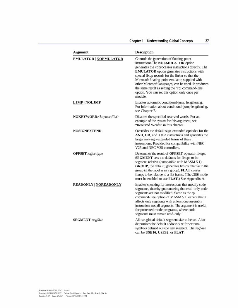
Chapter 1 Understanding Global Concepts 27
Filename: LMAPGC01.DOC Project: Template: MSGRIDA1.DOT Author: Terri Sharkey Last Saved By: Ruth L Silverio Revision #: 57 Page: 27 of 27 Printed: 10/02/00 04:24 PM
Argument Description
EMULATOR | NOEMULATOR Controls the generation of floating-point instructions.The NOEMULATOR option generates the coprocessor instructions directly. The EMULATOR option generates instructions with special fixup records for the linker so that the Microsoft floating-point emulator, supplied with other Microsoft languages, can be used. It produces the same result as setting the /Fpi command-line option. You can set this option only once per module.
LJMP | NOLJMP Enables automatic conditional-jump lengthening. For information about conditional-jump lengthening, see Chapter 7.
NOKEYWORD:<keywordlist> Disables the specified reserved words. For an example of the syntax for this argument, see “Reserved Words” in this chapter.
NOSIGNEXTEND Overrides the default sign-extended opcodes for the AND, OR, and XOR instructions and generates the larger non-sign-extended forms of these instructions. Provided for compatibility with NEC V25 and NEC V35 controllers.
OFFSET: offsettype Determines the result of OFFSET operator fixups. SEGMENT sets the defaults for fixups to be segment-relative (compatible with MASM 5.1). GROUP, the default, generates fixups relative to the group (if the label is in a group). FLAT causes fixups to be relative to a flat frame. (The .386 mode must be enabled to use FLAT.) See Appendix A.
READONLY | NOREADONLY Enables checking for instructions that modify code segments, thereby guaranteeing that read-only code segments are not modified. Same as the /p command-line option of MASM 5.1, except that it affects only segments with at least one assembly instruction, not all segments. The argument is useful for protected mode programs, where code segments must remain read-only.
SEGMENT: segSize Allows global default segment size to be set. Also determines the default address size for external symbols defined outside any segment. The segSize can be USE16, USE32, or FLAT.

28 Programmer’s Guide
Filename: LMAPGC01.DOC Project: Template: MSGRIDA1.DOT Author: Terri Sharkey Last Saved By: Ruth L Silverio Revision #: 57 Page: 28 of 28 Printed: 10/02/00 04:24 PM
Conditional Directives MASM 6.1 provides conditional-assembly directives and conditional-error directives. Conditional-assembly directives let you test for a specified condition and assemble a block of statements if the condition is true. Conditional-error directives allow you to test for a specified condition and generate an assembly error if the condition is true.
Both kinds of conditional directives test assembly-time conditions, not run-time conditions. You can test only expressions that evaluate to constants during assembly. For a list of the predefined symbols often used in conditional assembly, see “Predefined Symbols,” earlier in this chapter.
Conditional-Assembly Directives The IF and ENDIF directives enclose the conditional statements. The optional ELSEIF and ELSE blocks follow the IF directive. There are many forms of the IF and ELSE directives. Help provides a complete list.
The following statements show the syntax for the IF directives. The syntax for other condition-assembly directives follow the same form.
IF expression1 ifstatements [[ELSEIF expression2 elseifstatements]] [[ELSE elsestatements]] ENDIF
The statements within an IF block can be any valid instructions, including other conditional blocks, which in turn can contain any number of ELSEIF blocks. ENDIF ends the block.
MASM assembles the statements following the IF directive only if the corresponding condition is true. If the condition is not true and the block contains an ELSEIF directive, the assembler checks to see if the corresponding condition is true. If so, it assembles the statements following the ELSEIF directive. If no IF or ELSEIF conditions are satisfied, the assembler processes only the statements following the ELSE directive.
For example, you may want to assemble a line of code only if your program defines a particular variable. In this example,
IFDEF buffer buff BYTE buffer DUP(?) ENDIF
the assembler allocates buff only if buffer has been previously defined.
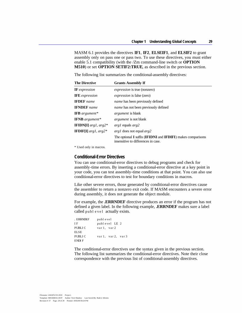
Chapter 1 Understanding Global Concepts 29
Filename: LMAPGC01.DOC Project: Template: MSGRIDA1.DOT Author: Terri Sharkey Last Saved By: Ruth L Silverio Revision #: 57 Page: 29 of 29 Printed: 10/02/00 04:24 PM
MASM 6.1 provides the directives IF1, IF2, ELSEIF1, and ELSIF2 to grant assembly only on pass one or pass two. To use these directives, you must either enable 5.1 compatibility (with the /Zm command-line switch or OPTION M510) or set OPTION SETIF2:TRUE, as described in the previous section.
The following list summarizes the conditional-assembly directives:
The Directive Grants Assembly If
IF expression expression is true (nonzero) IFE expression expression is false (zero) IFDEF name name has been previously defined IFNDEF name name has not been previously defined IFB argument* argument is blank IFNB argument* argument is not blank IFIDN[I] arg1, arg2* arg1 equals arg2 IFDIF[I] arg1, arg2* arg1 does not equal arg2
The optional I suffix (IFIDNI and IFDIFI) makes comparisons insensitive to differences in case.
* Used only in macros.
Conditional-Error Directives You can use conditional-error directives to debug programs and check for assembly-time errors. By inserting a conditional-error directive at a key point in your code, you can test assembly-time conditions at that point. You can also use conditional-error directives to test for boundary conditions in macros.
Like other severe errors, those generated by conditional-error directives cause the assembler to return a nonzero exit code. If MASM encounters a severe error during assembly, it does not generate the object module.
For example, the .ERRNDEF directive produces an error if the program has not defined a given label. In the following example, .ERRNDEF makes sure a label called publevel actually exists.
.ERRNDEF publevel IF publevel LE 2 PUBLIC var1, var2 ELSE PUBLIC var1, var2, var3 ENDIF
The conditional-error directives use the syntax given in the previous section. The following list summarizes the conditional-error directives. Note their close correspondence with the previous list of conditional-assembly directives.

30 Programmer’s Guide
Filename: LMAPGC01.DOC Project: Template: MSGRIDA1.DOT Author: Terri Sharkey Last Saved By: Ruth L Silverio Revision #: 57 Page: 30 of 30 Printed: 10/02/00 04:24 PM
The Directive Generates an Error
.ERR Unconditionally where it occurs in the source file. Usually placed within a conditional-assembly block.
.ERRE expression If expression is false (zero).
.ERRNZ expression If expression is true (nonzero).
.ERRDEF name If name has been defined.
.ERRNDEF name If name has not been defined.
.ERRB argument* If argument is blank.
.ERRNB argument* If argument is not blank.
.ERRIDN[I] arg1, arg2* If arg1 equals arg2.
.ERRDIF[I] arg1, arg2* If arg1 does not equal arg2.
The optional I suffix (.ERRIDNI and .ERRDIFI) makes comparisons insensitive to case.
* Used only in macros
Two special conditional-error directives, .ERR1 and .ERR2, generate an error only on pass one or pass two. To use these directives, you must either enable 5.1 compatibility (with the /Zm command-line switch or OPTION M510) or set OPTION SETIF2:TRUE, as described in the previous section.
31
Filename: LMAPGC02.DOC Project: Template: MSGRIDA1.DOT Author: Terri Sharkey Last Saved By: Ruth L Silverio Revision #: 38 Page: 31 of 1 Printed: 10/02/00 04:23 PM
C H A P T E R 2
Understanding segments is an essential part of programming in assembly language. In the family of 8086-based processors, the term segment has two meanings:
u A block of memory of discrete size, called a “physical segment.” The number of bytes in a physical memory segment is 64K for 16-bit processors or 4 gigabytes for 32-bit processors.
u A variable-sized block of memory, called a “logical segment,” occupied by a program’s code or data.
As you read this chapter, the distinction between the two definitions will become clear. The adjectives “physical” and “logical” are not often used when speaking of segments. The beginning programmer is left to infer from context which definition applies. Fortunately, this is not difficult, and a distinction is often not required.
This chapter begins with a close look at physical memory segments. This lays the foundation for understanding logical segments, which form the subject of most of the following sections.
The section “Using Simplified Segment Directives” explains how to begin, end, and organize segments. It also explains how to access far data and code with simplified segment directives.
The next section, “Using Full Segment Definitions,” describes how to order, combine, and divide segments, and how to use the SEGMENT directive to define full segments. It also explains how to create a segment group so that you can use one segment address to access all the data.
Most of the information in this chapter also applies to writing modules to be called from other programs. Exceptions are noted when they apply. For more information about multiple-module programming, see Chapter 8, “Sharing Data and Procedures Among Modules and Libraries.”
Organizing Segments
32 Programmer’s Guide
Filename: LMAPGC02.DOC Project: Template: MSGRIDA1.DOT Author: Terri Sharkey Last Saved By: Ruth L Silverio Revision #: 38 Page: 32 of 2 Printed: 10/02/00 04:23 PM
Physical Memory Segments As explained in Chapter 1, a physical segment can begin only at memory locations evenly divisible by 16, including address 0. Intel calls such locations “paragraphs.” You can easily recognize a paragraph location because its hexadecimal address always ends with 0, as in 10000h or 2EA70h. The 8086/286 processors allow segments 64K in size, the largest number 16 bits can represent. The 80386/486 processors still adhere to the 64K limit when running in real mode. In protected mode, however, they use 32-bit registers that can hold addresses up to 4 gigabytes.
Segmented architecture presents certain hurdles for the assembly-language programmer. For small programs, the limitations lose importance. Code and data each occupy less than 64K and reside in individual segments. A simple offset locates each variable or instruction within a segment.
Larger programs, however, must contend with problems of segmented memory areas. If data occupies two or more segments, the program must specify both segment and offset to access a variable. When the data forms a continuous stream across segments — such as the text in a word processor’s workspace — the problems become more acute. Whenever it adds or deletes text in the first segment, the word processor must seamlessly move data back and forth over the boundaries of each following segment.
The problem of segment boundaries disappears in the so-called flat address space of 32-bit protected mode. Although segments still exist, they easily hold all the code and data of the largest programs. Even a very large program becomes in effect a small application, able to reach all code and data with a single offset address.
Logical Segments Logical segments contain the three components of a program: code, data, and stack. MASM organizes the three parts for you so they occupy physical segments of memory. The segment registers CS, DS, and SS contain the addresses of the physical memory segments where the logical segments reside.
You can define segments in two ways: with simplified segment directives and with full segment definitions. You can also use both kinds of segment definitions in the same program.
Simplified segment directives hide many of the details of segment definition and assume the same conventions used by Microsoft high-level languages. (See the following section, “Using Simplified Segment Directives.”) The simplified segment directives generate necessary code, specify segment attributes, and arrange segment order.
Chapter 2 Organizing Segments 33
Filename: LMAPGC02.DOC Project: Template: MSGRIDA1.DOT Author: Terri Sharkey Last Saved By: Ruth L Silverio Revision #: 38 Page: 33 of 3 Printed: 10/02/00 04:23 PM
Full segment definitions require more complex syntax but provide more complete control over how the assembler generates segments. (See “Using Full Segment Definitions” later in this chapter.) If you use full segment definitions, you must write code to handle all the tasks performed automatically by the simplified segment directives.
Using Simplified Segment Directives Structuring a MASM program using simplified segments requires use of several directives to assign standard names, alignment, and attributes to the segments in your program. These directives define the segments in such a way that linking with Microsoft high-level languages is easy.
The simplified segment directives are .MODEL, .CODE, .CONST, .DATA, .DATA?, .FARDATA, .FARDATA?, .STACK, .STARTUP, and .EXIT. The following sections discuss these directives and the arguments they take.
MASM programs consist of modules made up of segments. Every program written only in MASM has one main module, where program execution begins. This main module can contain code, data, or stack segments defined with all of the simplified segment directives. Any additional modules should contain only code and data segments. Every module that uses simplified segments must, however, begin with the .MODEL directive.
The following example shows the structure of a main module using simplified segment directives. It uses the default processor (8086) and the default stack distance (NEARSTACK). Additional modules linked to this main program would use only the .MODEL, .CODE, and .DATA directives and the END statement.
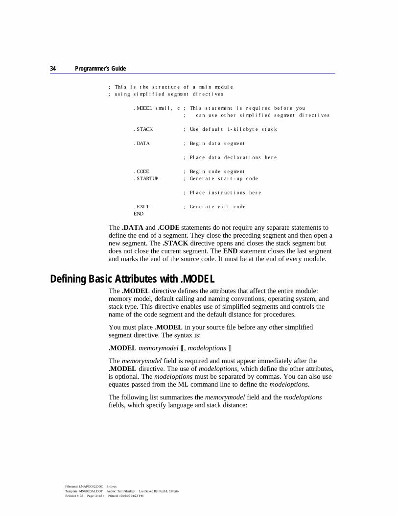
34 Programmer’s Guide
Filename: LMAPGC02.DOC Project: Template: MSGRIDA1.DOT Author: Terri Sharkey Last Saved By: Ruth L Silverio Revision #: 38 Page: 34 of 4 Printed: 10/02/00 04:23 PM
; This is the structure of a main module ; using simplified segment directives .MODEL small, c ; This statement is required before you ; can use other simplified segment directives .STACK ; Use default 1-kilobyte stack .DATA ; Begin data segment ; Place data declarations here .CODE ; Begin code segment .STARTUP ; Generate start-up code ; Place instructions here .EXIT ; Generate exit code END
The .DATA and .CODE statements do not require any separate statements to define the end of a segment. They close the preceding segment and then open a new segment. The .STACK directive opens and closes the stack segment but does not close the current segment. The END statement closes the last segment and marks the end of the source code. It must be at the end of every module.
Defining Basic Attributes with .MODEL The .MODEL directive defines the attributes that affect the entire module: memory model, default calling and naming conventions, operating system, and stack type. This directive enables use of simplified segments and controls the name of the code segment and the default distance for procedures.
You must place .MODEL in your source file before any other simplified segment directive. The syntax is:
.MODEL memorymodel [[, modeloptions ]]
The memorymodel field is required and must appear immediately after the .MODEL directive. The use of modeloptions, which define the other attributes, is optional. The modeloptions must be separated by commas. You can also use equates passed from the ML command line to define the modeloptions.
The following list summarizes the memorymodel field and the modeloptions fields, which specify language and stack distance:
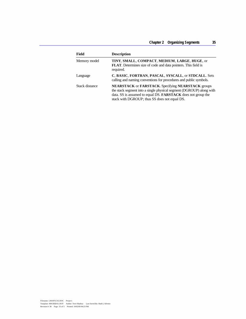
Chapter 2 Organizing Segments 35
Filename: LMAPGC02.DOC Project: Template: MSGRIDA1.DOT Author: Terri Sharkey Last Saved By: Ruth L Silverio Revision #: 38 Page: 35 of 5 Printed: 10/02/00 04:23 PM
Field Description
Memory model TINY, SMALL, COMPACT, MEDIUM, LARGE, HUGE, or FLAT. Determines size of code and data pointers. This field is required.
Language C, BASIC, FORTRAN, PASCAL, SYSCALL, or STDCALL. Sets calling and naming conventions for procedures and public symbols.
Stack distance NEARSTACK or FARSTACK. Specifying NEARSTACK groups the stack segment into a single physical segment (DGROUP) along with data. SS is assumed to equal DS. FARSTACK does not group the stack with DGROUP; thus SS does not equal DS.

36 Programmer’s Guide
Filename: LMAPGC02.DOC Project: Template: MSGRIDA1.DOT Author: Terri Sharkey Last Saved By: Ruth L Silverio Revision #: 38 Page: 36 of 6 Printed: 10/02/00 04:23 PM
You can use no more than one reserved word from each field. The following examples show how you can combine various fields:
.MODEL small ; Small memory model .MODEL large, c, farstack ; Large memory model, ; C conventions, ; separate stack .MODEL medium, pascal ; Medium memory model, ; Pascal conventions, ; near stack (default)
The next four sections give more detail on each field.
Defining the Memory Model MASM supports the standard memory models used by Microsoft high-level languages — tiny, small, medium, compact, large, huge, and flat. You specify the memory model with attributes of the same name placed after the .MODEL directive. With the exception of the flat model, which requires instructions specific to the 80386/486, your choice of a memory model does not limit the kind of instructions you can write. The memory model does, however, control segment defaults and determine whether data and code are near or far by default, as indicated in the following table.
Table 2.1 Attributes of Memory Models
Memory Model
Default Code
Default Data
Operating System
Data and Code Combined
Tiny Near Near MS-DOS Yes Small Near Near MS-DOS, Windows No Medium Far Near MS-DOS, Windows No Compact Near Far MS-DOS, Windows No Large Far Far MS-DOS, Windows No Huge Far Far MS-DOS, Windows No Flat Near Near Windows NT Yes
When writing assembler modules for a high-level language, you should use the same memory model as the calling language. Choose the smallest memory model available that can contain your data and code, since near references operate more efficiently than far references.
The predefined symbol @Model returns the memory model, encoding memory models as integers 1 through 7. For more information on predefined symbols, see “Predefined Symbols” in Chapter 1. For an example of how to use them, see Help.
Chapter 2 Organizing Segments 37
Filename: LMAPGC02.DOC Project: Template: MSGRIDA1.DOT Author: Terri Sharkey Last Saved By: Ruth L Silverio Revision #: 38 Page: 37 of 7 Printed: 10/02/00 04:23 PM
The seven memory models supported by MASM 6.1 fall into three groups, described in the following paragraphs.
Small, Medium, Compact, Large, and Huge Models The traditional memory models recognized by many languages are small, medium, compact, large, and huge. Small model supports one data segment and one code segment. All data and code are near by default. Large model supports multiple code and multiple data segments. All data and code are far by default. Medium and compact models are in-between. Medium model supports multiple code and single data segments; compact model supports multiple data segments and a single code segment.
Huge model implies individual data items larger than a single segment, but the implementation of huge data items must be coded by the programmer. Since the assembler provides no direct support for this feature, huge model is essentially the same as large model.
In each of these models, you can override the default. For example, you can make large data items far in small model, or internal procedures near in large model.
Tiny Model Tiny-model programs run only under MS-DOS. Tiny model places all data and code in a single segment. Therefore, the total program file size can occupy no more than 64K. The default is near for code and static data items; you cannot override this default. However, you can allocate far data dynamically at run time using MS-DOS memory allocation services.
Tiny model produces MS-DOS .COM files. Specifying .MODEL tiny automatically sends the /TINY argument to the linker. Therefore, the /AT argument is not necessary with .MODEL tiny. However, /AT does not insert a .MODEL directive. It only verifies that there are no base or pointer fixups, and sends /TINY to the linker.
Flat Model The flat memory model is a nonsegmented configuration available in 32-bit operating systems. It is similar to tiny model in that all code and data go in a single 32-bit segment.
To write a flat model program, specify the .386 or .486 directive before .MODEL FLAT. All data and code (including system resources) are in a single 32-bit segment. The operating system automatically initializes segment registers at load time; you need to modify them only when mixing 16-bit and 32-bit segments in a single application. CS, DS, ES, and SS all occupy the supergroup FLAT. Addresses and pointers passed to system services are always 32-bit near addresses and pointers.
38 Programmer’s Guide
Filename: LMAPGC02.DOC Project: Template: MSGRIDA1.DOT Author: Terri Sharkey Last Saved By: Ruth L Silverio Revision #: 38 Page: 38 of 8 Printed: 10/02/00 04:23 PM
Choosing the Language Convention The language option facilitates compatibility with high-level languages by determining the internal encoding for external and public symbol names, the code generated for procedure initialization and cleanup, and the order that arguments are passed to a procedure with INVOKE. It also facilitates compatibility with high-level – language modules. The PASCAL, BASIC, and FORTRAN conventions are identical. C and SYSCALL have the same calling convention but different naming conventions. Functions in the Windows API use the Pascal calling convention.
Procedure definitions (PROC) and high-level procedure calls (INVOKE) automatically generate code consistent with the calling convention of the specified language. The PROC, INVOKE, PUBLIC, and EXTERN directives all use the naming convention of the language. These directives follow the default language conventions from the .MODEL directive unless you specifically override the default. Use of these directives is explained in “Controlling Program Flow,” Chapter 7. You can also use the OPTION directive to set the language type. (See “Using the OPTION Directive” in Chapter 1.) Not specifying a language type in either the .MODEL, OPTION, EXTERN, PROC, INVOKE, or PROTO statement causes the assembler to generate an error.
The predefined symbol @Interface provides information about the language parameters. For a description of the bit flags, see Help.
For more information on calling and naming conventions, see Chapter 12, “Mixed-Language Programming.” For information about writing procedures and prototypes, see Chapter 7, “Controlling Program Flow.” For information on multiple-module programming, refer to Chapter 8, “Sharing Data and Procedures Among Modules and Libraries.”
Setting the Stack Distance The NEARSTACK keyword places the stack segment in the group DGROUP along with the data segment. The .STARTUP directive then generates code to adjust SS:SP so that SS (Stack Segment register) holds the same address as DS (Data Segment register). If you do not use .STARTUP, you must make this adjustment or your program may fail to run. (For information about startup code, see “Starting and Ending Code with .STARTUP and .EXIT,” later in this chapter.) In this case, you can use DS to access stack items (including parameters and local variables) and SS to access near data. Furthermore, since stack items share the same segment address as near data, you can reliably pass near pointers to stack items.
The FARSTACK setting gives the stack a segment of its own. That is, SS does not equal DS. The default stack type, NEARSTACK, is a convenient setting for
Chapter 2 Organizing Segments 39
Filename: LMAPGC02.DOC Project: Template: MSGRIDA1.DOT Author: Terri Sharkey Last Saved By: Ruth L Silverio Revision #: 38 Page: 39 of 9 Printed: 10/02/00 04:23 PM
most programs. Use FARSTACK for special cases such as memory-resident programs
40 Programmer’s Guide
Filename: LMAPGC02.DOC Project: Template: MSGRIDA1.DOT Author: Terri Sharkey Last Saved By: Ruth L Silverio Revision #: 38 Page: 40 of 10 Printed: 10/02/00 04:23 PM
and dynamic-link libraries (discussed in Chapters 10 and 11) when you cannot assume that the caller’s stack is near. You can use the predefined symbol @Stack to determine if the stack location is DGROUP (for near stacks) or STACK (for far stacks).
Specifying a Processor and Coprocessor MASM supports a set of directives for selecting processors and coprocessors. Once you select a processor, you must use only the instruction set for that processor. The default is the 8086 processor. If you always want your code to run on this processor, you do not need to add any processor directives.
To enable a different processor mode and the additional instructions available on that processor, use the directives .186, .286, .386, and .486. The instruction timings on a listing (see Appendix C, “Generating and Reading Assembly Listings”) correspond to whichever processor directive you select.
The .286P, .386P, and .486P directives enable the instructions available only at higher privilege levels in addition to the normal instruction set for the given processor. Generally, you don’t need privileged instructions unless you are writing operating-systems code or device drivers.
In addition to enabling different instruction sets, the processor directives also affect the behavior of extended language features. For example, the INVOKE directive pushes arguments onto the stack. If the .286 directive is in effect, INVOKE takes advantage of operations possible only on 80286 and later processors.
Use the directives .8087 (the default), .287, .387, and .NO87 to select a math coprocessor instruction set. The .NO87 directive turns off assembly of all coprocessor instructions. Note that .486 also enables assembly of all coprocessor instructions because the 80486 processor has a complete set of coprocessor registers and instructions built into the chip. The processor instructions imply the corresponding coprocessor directive. The coprocessor directives are provided to override the defaults.
Creating a Stack The stack is the section of memory used for pushing or popping registers and storing the return address when a subroutine is called. The stack often holds temporary and local variables.
If your main module is written in a high-level language, that language handles the details of creating a stack. Use the .STACK directive only when you write a main module in assembly language.
Chapter 2 Organizing Segments 41
Filename: LMAPGC02.DOC Project: Template: MSGRIDA1.DOT Author: Terri Sharkey Last Saved By: Ruth L Silverio Revision #: 38 Page: 41 of 11 Printed: 10/02/00 04:23 PM
The .STACK directive creates a stack segment. By default, the assembler allocates 1K of memory for the stack. This size is sufficient for most small programs.
42 Programmer’s Guide
Filename: LMAPGC02.DOC Project: Template: MSGRIDA1.DOT Author: Terri Sharkey Last Saved By: Ruth L Silverio Revision #: 38 Page: 42 of 12 Printed: 10/02/00 04:23 PM
To create a stack of a size other than the default size, give .STACK a single numeric argument indicating stack size in bytes:
.STACK 2048 ; Use 2K stack
For a description of how stack memory is used with procedure calls and local variables, see Chapter 7, “Controlling Program Flow.”
Creating Data Segments Programs can contain both near and far data. In general, you should place important and frequently used data in the near data area, where data access is faster. This area can get crowded, however, because in 16-bit operating systems the total amount of all near data in all modules cannot exceed 64K. Therefore, you may want to place infrequently used or particularly large data items in a far data segment.
The .DATA, .DATA?, .CONST, .FARDATA, and .FARDATA? directives create data segments. You can access the various segments within DGROUP without reloading segment registers (see “Defining Segment Groups,” later in this chapter). These five directives also prevent instructions from appearing in data segments by assuming CS to ERROR.
Near Data Segments The .DATA directive creates a near data segment. This segment contains the frequently used data for your program. It can occupy up to 64K in MS-DOS or 512 megabytes under flat model in Windows NT. It is placed in a special group identified as DGROUP, which is also limited to 64K.
When you use .MODEL, the assembler automatically defines DGROUP for your near data segment. The segments in DGROUP form near data, which can normally be accessed directly through DS or SS.
You can also define the .DATA? and .CONST segments that go into DGROUP unless you are using flat model. Although all of these segments (along with the stack) are eventually grouped together and handled as data segments, .DATA? and .CONST enhance compatibility with Microsoft high-level languages. In Microsoft languages, .CONST is used to define constant data such as strings and floating-point numbers that must be stored in memory. The .DATA? segment is used for storing uninitialized variables. You can follow this convention if you want. If you use C startup code, .DATA? is initialized to 0.
You can use @data to determine the group of the data segment and @DataSize to determine the size of the memory model set by the .MODEL directive. The predefined symbols @WordSize and @CurSeg return the size attribute and name of the current segment, respectively. See “Predefined Symbols” in Chapter 1.
Chapter 2 Organizing Segments 43
Filename: LMAPGC02.DOC Project: Template: MSGRIDA1.DOT Author: Terri Sharkey Last Saved By: Ruth L Silverio Revision #: 38 Page: 43 of 13 Printed: 10/02/00 04:23 PM
Far Data Segments The compact, large, and huge memory models use far data addresses by default. With these memory models, however, you can still construct data segments using .DATA, .DATA?, and .CONST. The effect of these directives does not change from one memory model to the next. They always contribute segments to the default data area, DGROUP, which has a total limit of 64K.
When you use .FARDATA or .FARDATA? in the small and medium memory models, the assembler creates far data segments FAR_DATA and FAR_BSS, respectively. You can access variables with:
mov ax, SEG farvar2 mov ds, ax
For more information on far data, see “Near and Far Addresses” in Chapter 3.
Creating Code Segments Whether you are writing a main module or a module to be called from another module, you can have both near and far code segments. This section explains how to use near and far code segments and how to use the directives and predefined equates that relate to code segments.
Near Code Segments The small memory model is often the best choice for assembly programs that are not linked to modules in other languages, especially if you do not need more than 64K of code. This memory model defaults to near (two-byte) addresses for code and data, which makes the program run faster and use less memory.
When you use .MODEL and simplified segment directives, the .CODE directive in your program instructs the assembler to start a code segment. The next segment directive closes the previous segment; the END directive at the end of your program closes remaining segments. The example at the beginning of “Using Simplified Segment Directives,” earlier in this chapter, shows how to do this.
You can use the predefined symbol @CodeSize to determine whether code pointers default to NEAR or FAR.
Far Code Segments When you need more than 64K of code, use the medium, large, or huge memory model to create far segments.
The medium, large, and huge memory models use far code addresses by default. In the larger memory models, the assembler creates a different code segment for each module. If you use multiple code segments in the small,
44 Programmer’s Guide
Filename: LMAPGC02.DOC Project: Template: MSGRIDA1.DOT Author: Terri Sharkey Last Saved By: Ruth L Silverio Revision #: 38 Page: 44 of 14 Printed: 10/02/00 04:23 PM
compact, or tiny model, the linker combines the .CODE segments for all modules into one segment.
For far code segments, the assembler names each code segment MODNAME_TEXT, in which MODNAME is the name of the module. With near code, the assembler names every code segment _TEXT, causing the linker to concatenate these segments into one. You can override the default name by providing an argument after .CODE. (For a complete list of segment names generated by MASM, see Appendix E, “Default Segment Names.”)
With far code, a single module can contain multiple code segments. The .CODE directive takes an optional text argument that names the segment. For instance, the following example creates two distinct code segments, FIRST_TEXT and SECOND_TEXT.
.CODE FIRST . . ; First set of instructions here . .CODE SECOND . . ; Second set of instructions here .
Whenever the processor executes a far call or jump, it loads CS with the new segment address. No special action is necessary other than making sure that you use far calls and jumps. See “Near and Far Addresses” in Chapter 3.
The assembler always assumes that the CS register contains the address of the current code segment or group.
Starting and Ending Code with .STARTUP and .EXIT The easiest way to begin and end an MS-DOS program is to use the .STARTUP and .EXIT directives in the main module. The main module contains the starting point and usually the termination point. You do not need these directives in a module called by another module.
These directives make MS-DOS programs easy to maintain. They automatically generate code appropriate to the stack distance specified with .MODEL. However, they do not apply to flat-model programs written for 32-bit operating systems. Thus, you should not use .STARTUP or .EXIT in programs written for Windows NT.
Note

Chapter 2 Organizing Segments 45
Filename: LMAPGC02.DOC Project: Template: MSGRIDA1.DOT Author: Terri Sharkey Last Saved By: Ruth L Silverio Revision #: 38 Page: 45 of 15 Printed: 10/02/00 04:23 PM
To start a program, place the .STARTUP directive where you want execution to begin. Usually, this location immediately follows the .CODE directive:
.CODE .STARTUP . . ; Place executable code here . .EXIT END
Note that .EXIT generates executable code, while END does not. The END directive informs the assembler that it has reached the end of the module. All modules must end with the END directive whether you use simplified or full segments.
If you do not use .STARTUP, you must give the starting address as an argument to the END directive. For example, the following fragment shows how to identify a program’s starting instruction with the label start:
.CODE start: . . ; Place executable code here . END start
Only the END directive for the module with the starting instruction should have an argument. When .STARTUP is present, the assembler ignores any argument to END.
For the default NEARSTACK attribute, .STARTUP points DS to DGROUP and sets SS:SP relative to DGROUP, generating the following code:

46 Programmer’s Guide
Filename: LMAPGC02.DOC Project: Template: MSGRIDA1.DOT Author: Terri Sharkey Last Saved By: Ruth L Silverio Revision #: 38 Page: 46 of 16 Printed: 10/02/00 04:23 PM
@Startup: mov dx, DGROUP mov ds, dx mov bx, ss sub bx, dx shl bx, 1 ; If .286 or higher, this is shl bx, 1 ; shortened to shl bx, 4 shl bx, 1 shl bx, 1 cli ; Not necessary in .286 or higher mov ss, dx add sp, bx sti ; Not necessary in .286 or higher . . . END @Startup
An MS-DOS program with the FARSTACK attribute does not need to adjust SS:SP, so .STARTUP just initializes DS, like this:
@Startup: mov dx, DGROUP mov ds, dx . . . END @Startup
When the program terminates, you can return an exit code to the operating system. Applications that check exit codes usually assume that an exit code of 0 means no problem occurred, and that an exit code of 1 means an error terminated the program. The .EXIT directive accepts a 1-byte exit code as its optional argument:
.EXIT 1 ; Return exit code 1
.EXIT generates the following code that returns control to MS-DOS, thus terminating the program. The return value, which can be a constant, memory reference, or 1-byte register, goes into AL:
mov al, value mov ah, 04Ch int 21h
If your program does not specify a return value, .EXIT returns whatever value happens to be in AL.

Chapter 2 Organizing Segments 47
Filename: LMAPGC02.DOC Project: Template: MSGRIDA1.DOT Author: Terri Sharkey Last Saved By: Ruth L Silverio Revision #: 38 Page: 47 of 17 Printed: 10/02/00 04:23 PM
Using Full Segment Definitions If you need complete control over segments, you can fully define the segments in your program. This section explains segment definitions, including how to order segments and how to define the segment types.
If you write a program under MS-DOS without .MODEL and .STARTUP, you must initialize registers yourself and use the END directive to indicate the starting address. The Windows operating system does not require you to initialize registers, as described in Chapter 3. For a description of typical startup code, see “Controlling the Segment Order,” later in this chapter.
Defining Segments with the SEGMENT Directive A defined segment begins with the SEGMENT directive and ends with the ENDS directive:
name SEGMENT [[align]] [[READONLY]] [[combine]] [[use]] [[’class’]] statements name ENDS
The name defines the name of the segment. Within a module, all segment definitions with the same name are treated as though they reference the same segment. The linker also combines identically named segments from different modules unless the combine type is PRIVATE. In addition, segments can be nested.
The optional types that follow the SEGMENT directive give the linker and the assembler instructions on how to set up and combine segments. The optional types, which are explained in detail in the following sections, include:
Type Description
align Defines the memory boundary on which a new segment begins. READONLY Tells the assembler to report an error if it detects an instruction
modifying any item in a READONLY segment. combine Determines how the linker combines segments from different modules
when building executable files. use (80386/486 only) Determines the size of a segment. USE16 indicates that offsets in the
segment are 16 bits wide. USE32 indicates 32-bit offsets. class Provides a class name for the segment. The linker automatically
groups segments of the same class in memory.
Types can be specified in any order. You can specify only one attribute from each of these fields; for example, you cannot have two different align types.
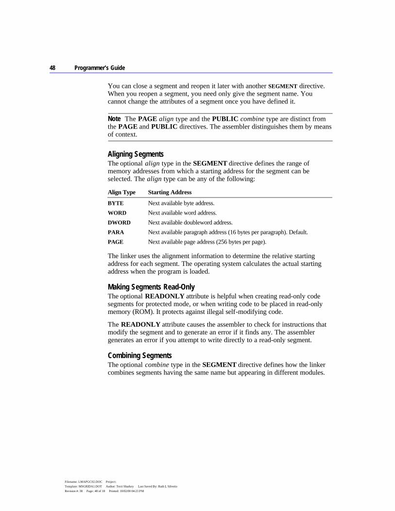
48 Programmer’s Guide
Filename: LMAPGC02.DOC Project: Template: MSGRIDA1.DOT Author: Terri Sharkey Last Saved By: Ruth L Silverio Revision #: 38 Page: 48 of 18 Printed: 10/02/00 04:23 PM
You can close a segment and reopen it later with another SEGMENT directive. When you reopen a segment, you need only give the segment name. You cannot change the attributes of a segment once you have defined it.
The PAGE align type and the PUBLIC combine type are distinct from the PAGE and PUBLIC directives. The assembler distinguishes them by means of context.
Aligning Segments The optional align type in the SEGMENT directive defines the range of memory addresses from which a starting address for the segment can be selected. The align type can be any of the following:
Align Type Starting Address
BYTE Next available byte address. WORD Next available word address. DWORD Next available doubleword address. PARA Next available paragraph address (16 bytes per paragraph). Default. PAGE Next available page address (256 bytes per page).
The linker uses the alignment information to determine the relative starting address for each segment. The operating system calculates the actual starting address when the program is loaded.
Making Segments Read-Only The optional READONLY attribute is helpful when creating read-only code segments for protected mode, or when writing code to be placed in read-only memory (ROM). It protects against illegal self-modifying code.
The READONLY attribute causes the assembler to check for instructions that modify the segment and to generate an error if it finds any. The assembler generates an error if you attempt to write directly to a read-only segment.
Combining Segments The optional combine type in the SEGMENT directive defines how the linker combines segments having the same name but appearing in different modules.
Note

Chapter 2 Organizing Segments 49
Filename: LMAPGC02.DOC Project: Template: MSGRIDA1.DOT Author: Terri Sharkey Last Saved By: Ruth L Silverio Revision #: 38 Page: 49 of 19 Printed: 10/02/00 04:23 PM
The combine type controls linker behavior, not assembler behavior. The combine types, which are described in full detail in Help, include:
Combine Type Linker Action
PRIVATE Does not combine the segment with segments from other modules, even if they have the same name. Default.
PUBLIC Concatenates all segments having the same name to form a single, contiguous segment.
STACK Concatenates all segments having the same name and causes the operating system to set SS:00 to the bottom and SS:SP to the top of the resulting segment. Data initialization is unreliable, as discussed following.
COMMON Overlaps segments. The length of the resulting area is the length of the largest of the combined segments. Data initialization is unreliable, as discussed following.
MEMORY Used as a synonym for the PUBLIC combine type. AT address Assumes address as the segment location. An AT segment cannot
contain any code or initialized data, but is useful for defining structures or variables that correspond to specific far memory locations, such as a screen buffer or low memory. You cannot use the AT combine type in protected-mode programs.
Do not place initialized data in STACK or COMMON segments. With these combine types, the linker overlays initialized data for each module at the beginning of the segment. The last module containing initialized data writes over any data from other modules.
Normally, you should provide at least one stack segment (having STACK combine type) in a program. If no stack segment is declared, LINK displays a warning message. You can ignore this message if you have a specific reason for not declaring a stack segment. For example, you would not have a separate stack segment in a MS-DOS tiny model (.COM) program, nor would you need a separate stack in a DLL that uses the caller’s stack.
Setting Segment Word Sizes (80386/486 Only) The use type in the SEGMENT directive specifies the segment word size on the 80386/486 processors. Segment word size determines the default operand and address size of all items in a segment.
The size attribute can be USE16, USE32, or FLAT. If you specify the .386 or .486 directive before the .MODEL directive, USE32 is the default. This attribute specifies that items in the segment are addressed with a 32-bit offset rather than a
Note
50 Programmer’s Guide
Filename: LMAPGC02.DOC Project: Template: MSGRIDA1.DOT Author: Terri Sharkey Last Saved By: Ruth L Silverio Revision #: 38 Page: 50 of 20 Printed: 10/02/00 04:23 PM
16-bit offset. If .MODEL precedes the .386 or .486 directive, USE16 is the default. To make USE32 the default, put .386 or .486 before .MODEL. You can override the USE32 default with the USE16 attribute, or vice versa.
Programs written for MS-DOS must not specify USE32. Mixing 16-bit and 32-bit segments in the same program is possible but usually applies only to systems programming.
Setting Segment Order with Class Type The optional class type in the SEGMENT directive helps control segment ordering. Two segments with the same name are not combined if their class is different. The linker arranges segments so that all segments identified with a given class type are next to each other in the executable file. However, within a particular class, the linker arranges segments in the order encountered. The .ALPHA, .SEQ, or .DOSSEG directive determines this order in each .OBJ file. The most common method for specifying a class type is to place all code segments first in the executable file.
Controlling the Segment Order The assembler normally positions segments in the object file in the order in which they appear in source code. The linker, in turn, processes object files in the order in which they appear on the command line. Within each object file, the linker outputs segments in the order they appear, subject to any group, class, and .DOSSEG requirements.
You can usually ignore segment ordering. However, it is important whenever you want certain segments to appear at the beginning or end of a program or when you make assumptions about which segments are next to each other in memory. For tiny model (.COM) programs, code segments must appear first in the executable file, because execution must start at the address 100h.
Segment Order Directives You can control the order in which segments appear in the executable program with three directives. The default, .SEQ, arranges segments in the order in which you declare them.
The .ALPHA directive specifies alphabetical segment ordering within a module. .ALPHA is provided for compatibility with early versions of the IBM assembler. If you have trouble running code from older books on assembly language, try using .ALPHA.
The .DOSSEG directive specifies the MS-DOS segment-ordering convention. It places segments in the standard order required by Microsoft languages. Do not use .DOSSEG in a module to be called from another module.
Note

Chapter 2 Organizing Segments 51
Filename: LMAPGC02.DOC Project: Template: MSGRIDA1.DOT Author: Terri Sharkey Last Saved By: Ruth L Silverio Revision #: 38 Page: 51 of 21 Printed: 10/02/00 04:23 PM
The .DOSSEG directive orders segments as follows:
1. Code segments 2. Data segments, in this order:
a. Segments not in class BSS or STACK b. Class BSS segments c. Class STACK segments
When you declare two or more segments to be in the same class, the linker automatically makes them contiguous. This rule overrides the segment-ordering directives. (For more about segment classes, see “Setting Segment Order with Class Type” in the previous section.)
Linker Control Most of the segment-ordering techniques (class names, .ALPHA, and .SEQ) control the order in which the assembler outputs segments. Usually, you are more interested in the order in which segments appear in the executable file. The linker controls this order.
The linker processes object files in the order in which they appear on the command line. Within each module, it then outputs segments in the order given in the object file. If the first module defines segments DSEG and STACK and the second module defines CSEG, then CSEG is output last. If you want to place CSEG first, there are two ways to do so.
The simpler method is to use .DOSSEG. This directive is output as a special record to the object file linker, and it tells the linker to use the Microsoft segment-ordering convention. This convention overrides command-line order of object files, and it places all segments of class 'CODE' first. (See “Defining Segments with the SEGMENT Directive,” previous.)
The other method is to define all the segments as early as possible (in an include file, for example, or in the first module). These definitions can be “dummy segments” — that is, segments with no content. The linker observes the segment ordering given, then later combines the empty segments with segments in other modules that have the same name.
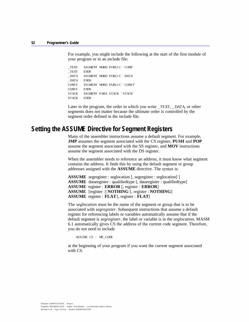
52 Programmer’s Guide
Filename: LMAPGC02.DOC Project: Template: MSGRIDA1.DOT Author: Terri Sharkey Last Saved By: Ruth L Silverio Revision #: 38 Page: 52 of 22 Printed: 10/02/00 04:23 PM
For example, you might include the following at the start of the first module of your program or in an include file:
_TEXT SEGMENT WORD PUBLIC 'CODE' _TEXT ENDS _DATA SEGMENT WORD PUBLIC 'DATA' _DATA ENDS CONST SEGMENT WORD PUBLIC 'CONST' CONST ENDS STACK SEGMENT PARA STACK 'STACK' STACK ENDS
Later in the program, the order in which you write _TEXT, _DATA, or other segments does not matter because the ultimate order is controlled by the segment order defined in the include file.
Setting the ASSUME Directive for Segment Registers Many of the assembler instructions assume a default segment. For example, JMP assumes the segment associated with the CS register, PUSH and POP assume the segment associated with the SS register, and MOV instructions assume the segment associated with the DS register.
When the assembler needs to reference an address, it must know what segment contains the address. It finds this by using the default segment or group addresses assigned with the ASSUME directive. The syntax is:
ASSUME segregister : seglocation [, segregister : seglocation] ] ASSUME dataregister : qualifiedtype [, dataregister : qualifiedtype] ASSUME register : ERROR [, register : ERROR] ASSUME [register :] NOTHING [, register : NOTHING] ASSUME register : FLAT [, register : FLAT]
The seglocation must be the name of the segment or group that is to be associated with segregister. Subsequent instructions that assume a default register for referencing labels or variables automatically assume that if the default segment is segregister, the label or variable is in the seglocation. MASM 6.1 automatically gives CS the address of the current code segment. Therefore, you do not need to include
ASSUME CS : MY_CODE
at the beginning of your program if you want the current segment associated with CS.

Chapter 2 Organizing Segments 53
Filename: LMAPGC02.DOC Project: Template: MSGRIDA1.DOT Author: Terri Sharkey Last Saved By: Ruth L Silverio Revision #: 38 Page: 53 of 23 Printed: 10/02/00 04:23 PM
Using the ASSUME directive to tell the assembler which segment to associate with a segment register is not the same as telling the processor. The ASSUME directive affects only assembly-time assumptions. You may need to use instructions to change run-time conditions. Initializing segment registers at run time is discussed in “Informing the Assembler About Segment Values,” Chapter 3.
The ASSUME directive can define a segment for each of the segment registers. The segregister can be CS, DS, ES, or SS (and FS and GS on the 80386/486). The seglocation must be one of the following:
u The name of a segment defined in the source file with the SEGMENT directive.
u The name of a group defined in the source file with the GROUP directive. u The keyword NOTHING, ERROR, or FLAT. u A SEG expression (see “Immediate Operands” in Chapter 3). u A string equate (text macro) that evaluates to a segment or group name (but
not a string equate that evaluates to a SEG expression).
It is legal to combine assumes to FLAT with assumes to specific segments. Combinations might be necessary in operating-system code that handles both 16- and 32-bit segments.
The keyword NOTHING cancels the current segment assumptions. For example, the statement ASSUME NOTHING cancels all register assumptions made by previous ASSUME statements.
Usually, a single ASSUME statement defines all four segment registers at the start of the source file. However, you can use the ASSUME directive at any point to change segment assumptions.
Using the ASSUME directive to change segment assumptions is often equivalent to changing assumptions with the segment-override operator (:). See “Direct Memory Operands” in Chapter 3. The segment-override operator is more convenient for one-time overrides. The ASSUME directive may be more convenient if previous assumptions must be overridden for a sequence of instructions.
However, in either case, your program must explicitly load a segment register with a segment address before accessing data within the segment. ASSUME only tells the assembler to assume that the register is correctly initialized; it does not by itself generate any code to load the register.
Note
54 Programmer’s Guide
Filename: LMAPGC02.DOC Project: Template: MSGRIDA1.DOT Author: Terri Sharkey Last Saved By: Ruth L Silverio Revision #: 38 Page: 54 of 24 Printed: 10/02/00 04:23 PM
You can also prevent the use of a register with:
ASSUME SegRegister : ERROR
The assembler generates an ASSUME CS:ERROR when you use simplified directives to create data segments, effectively preventing instructions or code labels from appearing in a data segment.
For more information about ASSUME, refer to “Defining Register Types with ASSUME” in Chapter 3.
Defining Segment Groups A group is a collection of segments totalling not more than 64K in 16-bit mode. A program addresses a code or data item in the group relative to the beginning of the group.
A group lets you develop separate logical segments for different kinds of data and then combine these into one segment (a group) for all the data. Using a group can save you from having to continually reload segment registers to access different segments. As a result, the program uses fewer instructions and runs faster.
The most common example of a group is the specially named group for near data, DGROUP. In the Microsoft segment model, several segments (_DATA, _BSS, CONST, and STACK) are combined into a single group called DGROUP. Microsoft high-level languages place all near data segments in this group. (By default, the stack is placed here, too.) The .MODEL directive automatically defines DGROUP. The DS register normally points to the beginning of the group, giving you relatively fast access to all data in DGROUP.
The syntax of the group directive is:
name GROUP segment [[, segment]]...
The name labels the group. It can refer to a group that was previously defined. This feature lets you add segments to a group one at a time. For example, if MYGROUP was previously defined to include ASEG and BSEG, then the statement
MYGROUP GROUP CSEG is perfectly legal. It simply adds CSEG to the group MYGROUP; ASEG and BSEG are not removed.
Each segment can be any valid segment name (including a segment defined later in source code), with one restriction: a segment cannot belong to more than one group.
Chapter 2 Organizing Segments 55
Filename: LMAPGC02.DOC Project: Template: MSGRIDA1.DOT Author: Terri Sharkey Last Saved By: Ruth L Silverio Revision #: 38 Page: 55 of 25 Printed: 10/02/00 04:23 PM
The GROUP directive does not affect the order in which segments of a group are loaded. You can place any number of 16-bit segments in a group as long as the total size does not exceed 65,536 bytes. If the processor is in 32-bit mode, the maximum size is 4 gigabytes. You need to make sure that non-grouped segments do not get placed between grouped segments in such a way that the size of the group exceeds 64K or 4 gigabytes. Neither can you place a 16-bit and a 32-bit segment in the same group.

53
Filename: LMAPGC03.DOC Project: Template: MSGRIDA1.DOT Author: Terri Sharkey Last Saved By: Ruth L Silverio Revision #: 49 Page: 53 of 1 Printed: 10/02/00 04:23 PM
C H A P T E R 3
MASM applications running in real mode require segmented addresses to access code and data. The address of the code or data in a segment is relative to a segment address in a segment register. You can also use pointers to access data in assembly language programs. (A pointer is a variable that contains an address as its value.)
The first section of this chapter describes how to initialize default segment registers to access near and far addresses. The next section describes how to access code and data. It also describes related operators, syntax, and displacements. The discussion of memory operands lays the foundation for the third section, which describes the stack.
The fourth section of this chapter explains how to use the TYPEDEF directive to declare pointers and the ASSUME directive to give the assembler information about registers containing pointers. This section also shows you how to do typical pointer operations and how to write code that works for pointer variables in any memory model.
Programming Segmented Addresses Before you use segmented addresses in your programs, you need to initialize the segment registers. The initialization process depends on the registers used and on your choice of simplified segment directives or full segment definitions. The simplified segment directives (introduced in Chapter 2) handle most of the initialization process for you. This section explains how to inform the assembler and the processor of segment addresses, and how to access the near and far code and data in those segments.
Initializing Default Segment Registers The segmented architecture of the 8086-family of processors does not require that you specify two addresses every time you access memory. As explained in Chapter 2, “Organizing Segments,” the 8086 family of processors uses a system
Using Addresses and Pointers

54 Programmer’s Guide
Filename: LMAPGC03.DOC Project: Template: MSGRIDA1.DOT Author: Terri Sharkey Last Saved By: Ruth L Silverio Revision #: 49 Page: 54 of 2 Printed: 10/02/00 04:23 PM
of default segment registers to simplify access to the most commonly used data and code.
The segment registers DS, SS, and CS are normally initialized to default segments at the beginning of a program. If you write the main module in a high-level language, the compiler initializes the segment registers. If you write the main module in assembly language, you must initialize the segment registers yourself. Follow these steps to initialize segments:
1. Tell the assembler which segment is associated with a register. The assembler must know the default segments at assembly time.
2. Tell the processor which segment is associated with a register by writing the necessary code to load the correct segment value into the segment register on the processor.
These steps are discussed separately in the following sections.
Informing the Assembler About Segment Values The first step in initializing segments is to tell the assembler which segment to associate with a register. You do this with the ASSUME directive. If you use simplified segment directives, the assembler automatically generates the appropriate ASSUME statements. If you use full segment definitions, you must code the ASSUME statements for registers other than CS yourself. (ASSUME can also be used on general-purpose registers, as explained in “Defining Register Types with ASSUME” later in this chapter.)
The .STARTUP directive generates startup code that sets DS equal to SS (unless you specify FARSTACK), allowing default data to be accessed through either SS or DS. This can improve efficiency in the code generated by compilers. The “DS equals SS” convention may not work with certain applications, such as memory-resident programs in MS-DOS and Windows dynamic-link libraries (see Chapter 10). The code generated for .STARTUP is shown in “Starting and Ending Code with .STARTUP and .EXIT” in Chapter 2. You can use similar code to set DS equal to SS in programs using full segment definitions.
Here is an example of ASSUME using full segment definitions:
ASSUME cs:_TEXT, ds:DGROUP, ss:DGROUP
This example is equivalent to the ASSUME statement generated with simplified segment directives in small model with NEARSTACK. Note that DS and SS are part of the same segment group. It is also possible to have different segments for data and code, and to use ASSUME to set ES, as shown here:
Chapter 3 Using Addresses and Pointers 55
Filename: LMAPGC03.DOC Project: Template: MSGRIDA1.DOT Author: Terri Sharkey Last Saved By: Ruth L Silverio Revision #: 49 Page: 55 of 3 Printed: 10/02/00 04:23 PM
ASSUME cs:MYCODE, ds:MYDATA, ss:MYSTACK, es:OTHER
Correct use of the ASSUME statement can help find addressing errors. With .CODE, the assembler assumes CS is the current segment. When you use the simplified segment directives .DATA, .DATA?, .CONST, .FARDATA, or .FARDATA?, the assembler automatically assumes CS is the ERROR segment. This prevents instructions from appearing in these segments. If you use full segment definitions, you can accomplish the same by placing ASSUME CS:ERROR in a data segment.
With simple or full segments, you can cancel the control of an ASSUME statement by assuming NOTHING. You can cancel the previous assumption for ES with the following statement:
ASSUME es:NOTHING
Prior to the .MODEL statement (or in its absence), the assembler sets the ASSUME statement for DS, ES, and SS to the current segment.
Informing the Processor About Segment Values The second and final step in initializing segments is to inform the processor of segment values at run time. How segment values are initialized at run time differs for each segment register and depends on the operating system and on your use of simplified segment directives or full segment definitions.
Specifying a Starting Address A program’s starting address determines where execution begins. After the operating system loads a program, it simply jumps to the starting address, giving processor control to the program. The true starting address is known only to the loader; the linker determines only the offset of the address within an undetermined code segment. That’s why a normal application is often referred to as “relocatable code,” because it runs regardless of where the loader places it in memory.
The offset of the starting address depends on the program type. Programs with an .EXE extension contain a header from which the loader reads the offset and combines it with a segment to form the starting address. Programs with a .COM extension (tiny model) have no such header, so by convention the loader jumps to the first byte of the program.
In either case, the .STARTUP directive identifies where execution begins, provided you use simplified segment directives. For an .EXE program, place .STARTUP immediately before the instruction where you want execution to start. In a .COM program, place .STARTUP before the first assembly instruction in your source code.

56 Programmer’s Guide
Filename: LMAPGC03.DOC Project: Template: MSGRIDA1.DOT Author: Terri Sharkey Last Saved By: Ruth L Silverio Revision #: 49 Page: 56 of 4 Printed: 10/02/00 04:23 PM
If you use full segment directives or prefer not to use .STARTUP, you must identify the starting instruction in two steps:
1. Label the starting instruction. 2. Provide the same label in the END directive.
These steps tell the linker where execution begins in the program. The following example illustrates the two steps for a tiny model program:
_TEXT SEGMENT WORD PUBLIC 'CODE' ORG 100h ; Use this declaration for .COM files only start: . ; First instruction here . . _TEXT ENDS END start ; Name of starting label
Notice the ORG statement in this example. This statement is mandatory in a tiny model program without the .STARTUP directive. It places the first instruction at offset 100h in the code segment to create space for a 256-byte (100h) data area called the Program Segment Prefix (PSP). The operating system takes care of initializing the PSP, so you need only make sure the area exists. (For a description of what data resides in the PSP, refer to the “Tables” chapter in the Reference.)
Initializing DS The DS register is automatically initialized to the correct value (DGROUP) if you use .STARTUP or if you are writing a program for Windows. If you do not use .STARTUP with MS-DOS, you must initialize DS using the following instructions:
mov ax, DGROUP mov ds, ax
The initialization requires two instructions because the segment name is a constant and the assembler does not allow a constant to be loaded directly to a segment register. The previous example loads DGROUP, but you can load any valid segment or group.
Initializing SS and SP The SS and SP registers are initialized automatically if you use the .STACK directive with simplified segments or if you define a segment that has the STACK combine type with full segment definitions. Using the STACK directive initializes SS to the stack segment. If you want SS to be equal to DS, use .STARTUP or its equivalent. (See “Combining Segments,” page 45.) For an .EXE file, the stack address is encoded into the executable header and resolved
Chapter 3 Using Addresses and Pointers 57
Filename: LMAPGC03.DOC Project: Template: MSGRIDA1.DOT Author: Terri Sharkey Last Saved By: Ruth L Silverio Revision #: 49 Page: 57 of 5 Printed: 10/02/00 04:23 PM
at load time. For a .COM file, the loader sets SS equal to CS and initializes SP to 0FFFEh.
If your program does not access far data, you do not need to initialize the ES register. If you choose to initialize, use the same technique as for the DS register. You can initialize SS to a far stack in the same way.
Near and Far Addresses Addresses that have an implied segment name or segment registers associated with them are called “near addresses.” Addresses that have an explicit segment associated with them are called “far addresses.” The assembler handles near and far code automatically, as described in the following sections. You must specify how to handle far data.
The Microsoft segment model puts all near data and the stack in a group called DGROUP. Near code is put in a segment called _TEXT. Each module’s far code or far data is placed in a separate segment. This convention is described in “Controlling the Segment Order” in Chapter 2.
The assembler cannot determine the address for some program components; these are said to be relocatable. The assembler generates a fixup record and the linker provides the address once it has determined the location of all segments. Usually a relocatable operand references a label, but there are exceptions. Examples in the next two sections include information about relocating near and far data.
Near Code Control transfers within near code do not require changes to segment registers. The processor automatically handles changes to the offset in the IP register when control-flow instructions such as JMP, CALL, and RET are used. The statement
call nearproc ; Change code offset
changes the IP register to the new address but leaves the segment unchanged. When the procedure returns, the processor resets IP to the offset of the next instruction after the CALL instruction.
Far Code The processor automatically handles segment register changes when dealing with far code. The statement
call farproc ; Change code segment and offset
automatically moves the segment and offset of the farproc procedure to the CS and IP registers. When the procedure returns, the processor sets CS to the
58 Programmer’s Guide
Filename: LMAPGC03.DOC Project: Template: MSGRIDA1.DOT Author: Terri Sharkey Last Saved By: Ruth L Silverio Revision #: 49 Page: 58 of 6 Printed: 10/02/00 04:23 PM
original code segment and sets IP to the offset of the next instruction after the call.
Near Data A program can access near data directly, because a segment register already holds the correct segment for the data item. The term “near data” is often used to refer to the data in the DGROUP group.
After the first initialization of the DS and SS registers, these registers normally point into DGROUP. If you modify the contents of either of these registers during the execution of the program, you must reload the register with DGROUP’s address before referencing any DGROUP data.
The processor assumes all memory references are relative to the segment in the DS register, with the exception of references using BP or SP. The processor associates these registers with the SS register. (You can override these assumptions with the segment override operator, described in “Direct Memory Operands,” on page 62.)
The following lines illustrate how the processor accesses either the DS or SS segments, depending on whether the pointer operand contains BP or SP. Note the distinction loses significance when DS and SS are equal.
nearvar WORD 0 . . . mov ax, nearvar ; Reads from DS:[nearvar] mov di, [bx] ; Reads from DS:[bx] mov [di], cx ; Writes to DS:[di] mov [bp+6], ax ; Writes to SS:[bp+6] mov bx, [bp] ; Reads from SS:[bp]
Far Data To read or modify a far address, a segment register must point to the segment of the data. This requires two steps. First load the segment (normally either ES or DS) with the correct value, and then (optionally) set an assume of the segment register to the segment of the address.
Flat model does not require far addresses. By default, all addressing is relative to the initial values of the segment registers. Therefore, this section on far addressing does not apply to flat model programs.
One method commonly used to access far data is to initialize the ES segment register. This example shows two ways to do this:
Note

Chapter 3 Using Addresses and Pointers 59
Filename: LMAPGC03.DOC Project: Template: MSGRIDA1.DOT Author: Terri Sharkey Last Saved By: Ruth L Silverio Revision #: 49 Page: 59 of 7 Printed: 10/02/00 04:23 PM
; First method mov ax, SEG farvar ; Load segment of the mov es, ax , far address into ES mov ax, es:farvar ; Provide an explicit segment ; override on the addressing
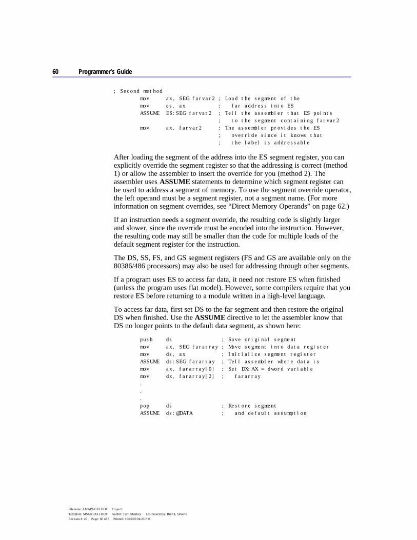
60 Programmer’s Guide
Filename: LMAPGC03.DOC Project: Template: MSGRIDA1.DOT Author: Terri Sharkey Last Saved By: Ruth L Silverio Revision #: 49 Page: 60 of 8 Printed: 10/02/00 04:23 PM
; Second method mov ax, SEG farvar2 ; Load the segment of the mov es, ax ; far address into ES ASSUME ES:SEG farvar2 ; Tell the assembler that ES points ; to the segment containing farvar2 mov ax, farvar2 ; The assembler provides the ES ; override since it knows that ; the label is addressable
After loading the segment of the address into the ES segment register, you can explicitly override the segment register so that the addressing is correct (method 1) or allow the assembler to insert the override for you (method 2). The assembler uses ASSUME statements to determine which segment register can be used to address a segment of memory. To use the segment override operator, the left operand must be a segment register, not a segment name. (For more information on segment overrides, see “Direct Memory Operands” on page 62.)
If an instruction needs a segment override, the resulting code is slightly larger and slower, since the override must be encoded into the instruction. However, the resulting code may still be smaller than the code for multiple loads of the default segment register for the instruction.
The DS, SS, FS, and GS segment registers (FS and GS are available only on the 80386/486 processors) may also be used for addressing through other segments.
If a program uses ES to access far data, it need not restore ES when finished (unless the program uses flat model). However, some compilers require that you restore ES before returning to a module written in a high-level language.
To access far data, first set DS to the far segment and then restore the original DS when finished. Use the ASSUME directive to let the assembler know that DS no longer points to the default data segment, as shown here:
push ds ; Save original segment mov ax, SEG fararray ; Move segment into data register mov ds, ax ; Initialize segment register ASSUME ds:SEG fararray ; Tell assembler where data is mov ax, fararray[0] ; Set DX:AX = dword variable mov dx, fararray[2] ; fararray . . . pop ds ; Restore segment ASSUME ds:@DATA ; and default assumption
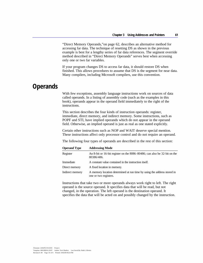
Chapter 3 Using Addresses and Pointers 61
Filename: LMAPGC03.DOC Project: Template: MSGRIDA1.DOT Author: Terri Sharkey Last Saved By: Ruth L Silverio Revision #: 49 Page: 61 of 9 Printed: 10/02/00 04:23 PM
“Direct Memory Operands,”on page 62, describes an alternative method for accessing far data. The technique of resetting DS as shown in the previous example is best for a lengthy series of far data references. The segment override method described in “Direct Memory Operands” serves best when accessing only one or two far variables.
If your program changes DS to access far data, it should restore DS when finished. This allows procedures to assume that DS is the segment for near data. Many compilers, including Microsoft compilers, use this convention.
Operands With few exceptions, assembly language instructions work on sources of data called operands. In a listing of assembly code (such as the examples in this book), operands appear in the operand field immediately to the right of the instructions.
This section describes the four kinds of instruction operands: register, immediate, direct memory, and indirect memory. Some instructions, such as POPF and STI, have implied operands which do not appear in the operand field. Otherwise, an implied operand is just as real as one stated explicitly.
Certain other instructions such as NOP and WAIT deserve special mention. These instructions affect only processor control and do not require an operand.
The following four types of operands are described in the rest of this section:
Operand Type Addressing Mode
Register An 8-bit or 16-bit register on the 8086–80486; can also be 32-bit on the 80386/486.
Immediate A constant value contained in the instruction itself. Direct memory A fixed location in memory.
Indirect memory A memory location determined at run time by using the address stored in one or two registers.
Instructions that take two or more operands always work right to left. The right operand is the source operand. It specifies data that will be read, but not changed, in the operation. The left operand is the destination operand. It specifies the data that will be acted on and possibly changed by the instruction.
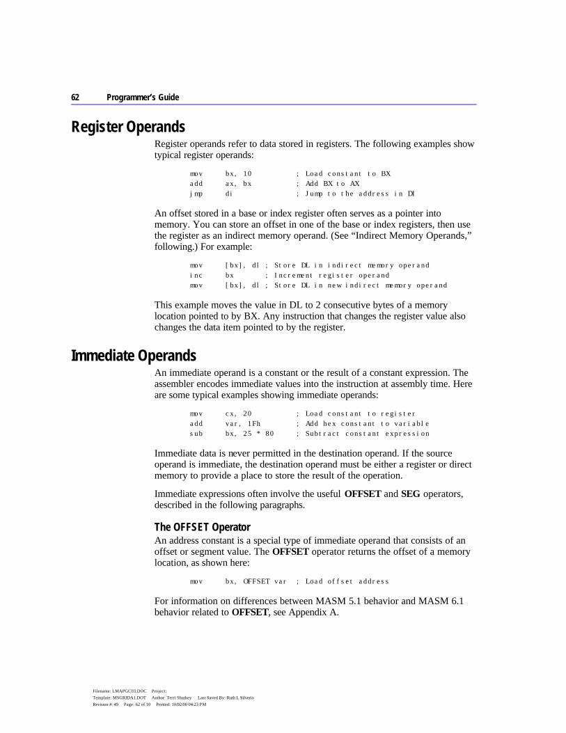
62 Programmer’s Guide
Filename: LMAPGC03.DOC Project: Template: MSGRIDA1.DOT Author: Terri Sharkey Last Saved By: Ruth L Silverio Revision #: 49 Page: 62 of 10 Printed: 10/02/00 04:23 PM
Register Operands Register operands refer to data stored in registers. The following examples show typical register operands:
mov bx, 10 ; Load constant to BX add ax, bx ; Add BX to AX jmp di ; Jump to the address in DI
An offset stored in a base or index register often serves as a pointer into memory. You can store an offset in one of the base or index registers, then use the register as an indirect memory operand. (See “Indirect Memory Operands,” following.) For example:
mov [bx], dl ; Store DL in indirect memory operand inc bx ; Increment register operand mov [bx], dl ; Store DL in new indirect memory operand
This example moves the value in DL to 2 consecutive bytes of a memory location pointed to by BX. Any instruction that changes the register value also changes the data item pointed to by the register.
Immediate Operands An immediate operand is a constant or the result of a constant expression. The assembler encodes immediate values into the instruction at assembly time. Here are some typical examples showing immediate operands:
mov cx, 20 ; Load constant to register add var, 1Fh ; Add hex constant to variable sub bx, 25 * 80 ; Subtract constant expression
Immediate data is never permitted in the destination operand. If the source operand is immediate, the destination operand must be either a register or direct memory to provide a place to store the result of the operation.
Immediate expressions often involve the useful OFFSET and SEG operators, described in the following paragraphs.
The OFFSET Operator An address constant is a special type of immediate operand that consists of an offset or segment value. The OFFSET operator returns the offset of a memory location, as shown here:
mov bx, OFFSET var ; Load offset address
For information on differences between MASM 5.1 behavior and MASM 6.1 behavior related to OFFSET, see Appendix A.
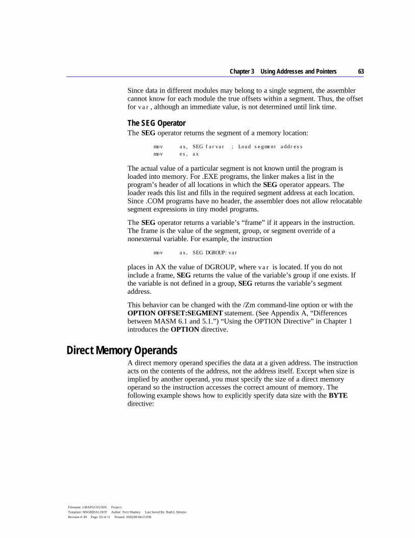
Chapter 3 Using Addresses and Pointers 63
Filename: LMAPGC03.DOC Project: Template: MSGRIDA1.DOT Author: Terri Sharkey Last Saved By: Ruth L Silverio Revision #: 49 Page: 63 of 11 Printed: 10/02/00 04:23 PM
Since data in different modules may belong to a single segment, the assembler cannot know for each module the true offsets within a segment. Thus, the offset for var, although an immediate value, is not determined until link time.
The SEG Operator The SEG operator returns the segment of a memory location:
mov ax, SEG farvar ; Load segment address mov es, ax
The actual value of a particular segment is not known until the program is loaded into memory. For .EXE programs, the linker makes a list in the program’s header of all locations in which the SEG operator appears. The loader reads this list and fills in the required segment address at each location. Since .COM programs have no header, the assembler does not allow relocatable segment expressions in tiny model programs.
The SEG operator returns a variable’s “frame” if it appears in the instruction. The frame is the value of the segment, group, or segment override of a nonexternal variable. For example, the instruction
mov ax, SEG DGROUP:var
places in AX the value of DGROUP, where var is located. If you do not include a frame, SEG returns the value of the variable’s group if one exists. If the variable is not defined in a group, SEG returns the variable’s segment address.
This behavior can be changed with the /Zm command-line option or with the OPTION OFFSET:SEGMENT statement. (See Appendix A, “Differences between MASM 6.1 and 5.1.”) “Using the OPTION Directive” in Chapter 1 introduces the OPTION directive.
Direct Memory Operands A direct memory operand specifies the data at a given address. The instruction acts on the contents of the address, not the address itself. Except when size is implied by another operand, you must specify the size of a direct memory operand so the instruction accesses the correct amount of memory. The following example shows how to explicitly specify data size with the BYTE directive:

64 Programmer’s Guide
Filename: LMAPGC03.DOC Project: Template: MSGRIDA1.DOT Author: Terri Sharkey Last Saved By: Ruth L Silverio Revision #: 49 Page: 64 of 12 Printed: 10/02/00 04:23 PM
.DATA? ; Segment for uninitialized data var BYTE ? ; Reserve one byte, labeled "var" .CODE . . . mov var, al ; Copy AL to byte at var
Any location in memory can be a direct memory operand as long as a size is specified (or implied) and the location is fixed. The data at the address can change, but the address cannot. By default, instructions that use direct memory addressing use the DS register. You can create an expression that points to a memory location using any of the following operators:
Operator Name Symbol
Plus + Minus – Index [ ] Structure member . Segment override :
These operators are discussed in more detail in the following section.
Plus, Minus, and Index The plus and index operators perform in exactly the same way when applied to direct memory operands. For example, both the following statements move the second word value from an array into the AX register:
mov ax, array[2] mov ax, array+2
The index operator can contain any direct memory operand. The following statements are equivalent:
mov ax, var mov ax, [var]
Some programmers prefer to enclose the operand in brackets to show that the contents, not the address, are used.
Chapter 3 Using Addresses and Pointers 65
Filename: LMAPGC03.DOC Project: Template: MSGRIDA1.DOT Author: Terri Sharkey Last Saved By: Ruth L Silverio Revision #: 49 Page: 65 of 13 Printed: 10/02/00 04:23 PM
The minus operator behaves as you would expect. Both the following instructions retrieve the value located at the word preceding array:
mov ax, array[-2] mov ax, array-2
Structure Field The structure operator (.) references a particular element of a structure or “field,” to use C terminology:
mov bx, structvar.field1
The address of the structure operand is the sum of the offsets of structvar and field1. For more information about structures, see “Structures and Unions” in Chapter 5.
Segment Override The segment override operator (:) specifies a segment portion of the address that is different from the default segment. When used with instructions, this operator can apply to segment registers or segment names:
mov ax, es:farvar ; Use segment override
The assembler will not generate a segment override if the default segment is explicitly provided. Thus, the following two statements assemble in exactly the same way:
mov [bx], ax mov ds:[bx], ax
A segment name override or the segment override operator identifies the operand as an address expression.
mov WORD PTR FARSEG:0, ax ; Segment name override mov WORD PTR es:100h, ax ; Legal and equivalent mov WORD PTR es:[100h], ax ; expressions ; mov WORD PTR [100h], ax ; Illegal, not an address
As the example shows, a constant expression cannot be an address expression unless it has a segment override.
Indirect Memory Operands Like direct memory operands, indirect memory operands specify the contents of a given address. However, the processor calculates the address at run time by referring to the contents of registers. Since values in the registers can change at run time, indirect memory operands provide dynamic access to memory.
66 Programmer’s Guide
Filename: LMAPGC03.DOC Project: Template: MSGRIDA1.DOT Author: Terri Sharkey Last Saved By: Ruth L Silverio Revision #: 49 Page: 66 of 14 Printed: 10/02/00 04:23 PM
Indirect memory operands make possible run-time operations such as pointer indirection and dynamic indexing of array elements, including indexing of multidimensional arrays.
Strict rules govern which registers you can use for indirect memory operands under 16-bit versions of the 8086-based processors. The rules change significantly for 32-bit processors starting with the 80386. However, the new rules apply only to code that does not need to be compatible with earlier processors.
This section covers features of indirect operands in either mode. The specific 16-bit rules and 32-bit rules are then explained separately.
Indirect Operands with 16- and 32-Bit Registers Some rules and options for indirect memory operands always apply, regardless of the size of the register. For example, you must always specify the register and operand size for indirect memory operands. But you can use various syntaxes to indicate an indirect memory operand. This section describes the rules that apply to both 16-bit and 32-bit register modes.
Specifying Indirect Memory Operands The index operator specifies the register or registers for indirect operands. The processor uses the data pointed to by the register. For example, the following instruction moves into AX the word value at the address in DS:BX.
mov ax, WORD PTR [bx]
When you specify more than one register, the processor adds the contents of the two addresses together to determine the effective address (the address of the data to operate on):
mov ax, [bx+si]
Specifying Displacements You can specify an address displacement, which is a constant value added to the effective address. A direct memory specifier is the most common displacement:
mov ax, table[si]
In this relocatable expression, the displacement table is the base address of an array; SI holds an index to an array element. The SI value is calculated at run time, often in a loop. The element loaded into AX depends on the value of SI at the time the instruction executes.

Chapter 3 Using Addresses and Pointers 67
Filename: LMAPGC03.DOC Project: Template: MSGRIDA1.DOT Author: Terri Sharkey Last Saved By: Ruth L Silverio Revision #: 49 Page: 67 of 15 Printed: 10/02/00 04:23 PM
Each displacement can be an address or numeric constant. If there is more than one displacement, the assembler totals them at assembly time and encodes the total displacement. For example, in the statement
table WORD 100 DUP (0) . . . mov ax, table[bx][di]+6
both table and 6 are displacements. The assembler adds the value of 6 to table to get the total displacement. However, the statement
mov ax, mem1[si] + mem2
is not legal, because it attempts to use a single command to join the contents of two different addresses.
Specifying Operand Size You must give the size of an indirect memory operand in one of three ways:
u By the variable’s declared size u With the PTR operator u Implied by the size of the other operand
The following lines illustrate all three methods. Assume the size of the table array is WORD, as declared earlier.
mov table[bx], 0 ; 2 bytes - from size of table mov BYTE PTR table, 0 ; 1 byte - specified by BYTE mov ax, [bx] ; 2 bytes - implied by AX
Syntax Options The assembler allows a variety of syntaxes for indirect memory operands. However, all registers must be inside brackets. You can enclose each register in its own pair of brackets, or you can place the registers in the same pair of brackets separated by a plus operator (+). All the following variations are legal and assemble the same way:
mov ax, table[bx][di] mov ax, table[di][bx] mov ax, table[bx+di] mov ax, [table+bx+di] mov ax, [bx][di]+table
All of these statements move the value in table indexed by BX+DI into AX.

68 Programmer’s Guide
Filename: LMAPGC03.DOC Project: Template: MSGRIDA1.DOT Author: Terri Sharkey Last Saved By: Ruth L Silverio Revision #: 49 Page: 68 of 16 Printed: 10/02/00 04:23 PM
Scaling Indexes The value of index registers pointing into arrays must often be adjusted for zero-based arrays and scaled according to the size of the array items. For a word array, the item number must be multiplied by two (shifted left by one place). When using 16-bit registers, you must scale with separate instructions, as shown here:
mov bx, 5 ; Get sixth element (adjust for 0) shl bx, 1 ; Scale by two (word size) inc wtable[bx] ; Increment sixth element in table
When using 32-bit registers on the 80386/486 processor, you can include scaling in the operand, as described in “Indirect Memory Operands with 32-Bit Registers,” following.
Accessing Structure Elements The structure member operator can be used in indirect memory operands to access structure elements. In this example, the structure member operator loads the year field of the fourth element of the students array into AL:
STUDENT STRUCT grade WORD ? name BYTE 20 DUP (?) year BYTE ? STUDENT ENDS students STUDENT < > . . ; Assume array is initialized mov bx, OFFSET students ; Point to array of students mov ax, 4 ; Get fourth element mov di, SIZE STUDENT ; Get size of STUDENT mul di ; Multiply size times mov di, ax ; elements to point DI ; to current element mov al, (STUDENT PTR[bx+di]).year
For more information on MASM structures, see “Structures and Unions” in Chapter 5.
Indirect Memory Operands with 16-Bit Registers For 8086-based computers and MS-DOS, you must follow the strict indexing rules established for the 8086 processor. Only four registers are allowed — BP, BX, SI, and DI — those only in certain combinations.
Chapter 3 Using Addresses and Pointers 69
Filename: LMAPGC03.DOC Project: Template: MSGRIDA1.DOT Author: Terri Sharkey Last Saved By: Ruth L Silverio Revision #: 49 Page: 69 of 17 Printed: 10/02/00 04:23 PM
BP and BX are base registers. SI and DI are index registers. You can use either a base or an index register by itself. But if you combine two registers, one must be a base and one an index. Here are legal and illegal forms:
mov ax, [bx+di] ; Legal mov ax, [bx+si] ; Legal mov ax, [bp+di] ; Legal mov ax, [bp+si] ; Legal ; mov ax, [bx+bp] ; Illegal - two base registers ; mov ax, [di+si] ; Illegal - two index registers
Table 3.1 shows the register modes in which you can specify indirect memory operands.
Table 3.1 Indirect Addressing with 16-Bit Registers
Mode Syntax Effective Address
Register indirect [BX] [BP] [DI] [SI]
Contents of register
Base or index displacement[BX] displacement[BP] displacement[DI] displacement[SI]
Contents of register plus displacement
Base plus index [BX][DI] [BP][DI] [BX][SI] [BP][SI]
Contents of base register plus contents of index register
Base plus index with displacement
displacement[BX][DI] displacement[BP][DI] displacement[BX][SI] displacement[BP][SI]
Sum of base register, index register, and displacement
Different combinations of registers and displacements have different timings, as shown in Reference.
Indirect Memory Operands with 32-Bit Registers You can write instructions for the 80386/486 processor using either 16-bit or 32-bit segments. Indirect memory operands are different in each case.
In 16-bit real mode, the 80386/486 operates the same way as earlier 8086-based processors, with one difference: you can use 32-bit registers. If the 80386/486 processor is enabled (with the .386 or .486 directive), 32-bit general-purpose registers are available with either 16-bit or 32-bit segments. Thirty-two–bit
70 Programmer’s Guide
Filename: LMAPGC03.DOC Project: Template: MSGRIDA1.DOT Author: Terri Sharkey Last Saved By: Ruth L Silverio Revision #: 49 Page: 70 of 18 Printed: 10/02/00 04:23 PM
registers eliminate many of the limitations of 16-bit indirect memory operands. You can use 80386/486 features to make your MS-DOS programs run faster and more efficiently if you are willing to sacrifice compatibility with earlier processors.
In 32-bit mode, an offset address can be up to 4 gigabytes. (Segments are still represented in 16 bits.) This effectively eliminates size restrictions on each segment, since few programs need 4 gigabytes of memory. Windows NT uses 32-bit mode and flat model, which spans all segments. XENIX 386 uses 32-bit mode with multiple segments.
80386/486 Enhancements On the 80386/486, the processor allows you to use any general-purpose 32-bit register as a base or index register, except ESP, which can be a base but not an index. However, you cannot combine 16-bit and 32-bit registers. Several examples are shown here:
add edx, [eax] ; Add double mov dl, [esp+10] ; Copy byte from stack dec WORD PTR [edx][eax] ; Decrement word cmp ax, array[ebx][ecx] ; Compare word from array jmp FWORD PTR table[ecx] ; Jump into pointer table
Scaling Factors With 80386/486 registers, the index register can have a scaling factor of 1, 2, 4, or 8. Any register except ESP can be the index register and can have a scaling factor. To specify the scaling factor, use the multiplication operator (*) adjacent to the register.
You can use scaling to index into arrays with different sizes of elements. For example, the scaling factor is 1 for byte arrays (no scaling needed), 2 for word arrays, 4 for doubleword arrays, and 8 for quadword arrays. There is no performance penalty for using a scaling factor. Scaling is illustrated in the following examples:
mov eax, darray[edx*4] ; Load double of double array mov eax, [esi*8][edi] ; Load double of quad array mov ax, wtbl[ecx+2][edx*2] ; Load word of word array
Scaling is also necessary on earlier processors, but it must be done with separate instructions before the indirect memory operand is used, as described in “Indirect Memory Operands with 16-Bit Registers,” previous.
The default segment register is SS if the base register is EBP or ESP. However, if EBP is scaled, the processor treats it as an index register with a value relative to DS, not SS.
Chapter 3 Using Addresses and Pointers 71
Filename: LMAPGC03.DOC Project: Template: MSGRIDA1.DOT Author: Terri Sharkey Last Saved By: Ruth L Silverio Revision #: 49 Page: 71 of 19 Printed: 10/02/00 04:23 PM
All other base registers are relative to DS. If two registers are used, only one can have a scaling factor. The register with the scaling factor is defined as the index register. The other register is defined as the base. If scaling is not used, the first register is the base. If only one register is used, it is considered the base for deciding the default segment unless it is scaled. The following examples illustrate how to determine the base register:
mov eax, [edx][ebp*4] ; EDX base (not scaled - seg DS) mov eax, [edx*1][ebp] ; EBP base (not scaled - seg SS) mov eax, [edx][ebp] ; EDX base (first - seg DS) mov eax, [ebp][edx] ; EBP base (first - seg SS) mov eax, [ebp] ; EBP base (only - seg SS) mov eax, [ebp*2] ; EBP*2 index (seg DS)
Mixing 16-Bit and 32-Bit Registers Assembly statements can mix 16-bit and 32-bit registers. For example, the following statement is legal for 16-bit and 32-bit segments:
mov eax, [bx]
This statement moves the 32-bit value pointed to by BX into the EAX register. Although BX is a 16-bit pointer, it can still point into a 32-bit segment.
However, the following statement is never legal, since you cannot use the CX register as a 16-bit pointer:
; mov eax, [cx] ; illegal
Operands that mix 16-bit and 32-bit registers are also illegal:
; mov eax, [ebx+si] ; illegal
The following statement is legal in either 16-bit or 32-bit mode:
mov bx, [eax]
This statement moves the 16-bit value pointed to by EAX into the BX register. This works in 32-bit mode. However, in 16-bit mode, moving a 32-bit pointer into a 16-bit segment is illegal. If EAX contains a 16-bit value (the top half of the 32-bit register is 0), the statement works. However, if the top half of the EAX register is not 0, the operand points into a part of the segment that doesn’t exist, generating an error. If you use 32-bit registers as indexes in 16-bit mode, you must make sure that the index registers contain valid 16-bit addresses.
The Program Stack The preceding discussion on memory operands lays the groundwork for understanding the important data area known as the “stack.”
72 Programmer’s Guide
Filename: LMAPGC03.DOC Project: Template: MSGRIDA1.DOT Author: Terri Sharkey Last Saved By: Ruth L Silverio Revision #: 49 Page: 72 of 20 Printed: 10/02/00 04:23 PM
A stack is an area of memory for storing data temporarily. Unlike other segments that store data starting from low memory, the stack stores data starting from high memory. Data is always pushed onto, or “popped” from the top of the stack.
The stack gets its name from its similarity to the spring-loaded plate holders in cafeterias. You add and remove plates from only the top of the stack. To retrieve the third plate, you must remove — that is, “pop” — the first two plates. Stacks are often referred to as LIFO buffers, from their last-in-first-out operation.
A stack is an essential part of any nontrivial program. A program continually uses its stack to temporarily store return addresses, procedure arguments, memory data, flags, or registers.
The SP register serves as an indirect memory operand to the top of the stack. At first, the stack is an uninitialized segment of a finite size. As your program adds data to the stack, the stack grows downward from high memory to low memory. When you remove items from the stack, it shrinks upward from low to high memory.
Saving Operands on the Stack The PUSH instruction stores a 2-byte operand on the stack. The POP instruction retrieves the most recent pushed value. When a value is pushed onto the stack, the assembler decreases the SP (Stack Pointer) register by 2. On 8086-based processors, the SP register always points to the top of the stack. The PUSH and POP instructions use the SP register to keep track of the current position.
When a value is popped off the stack, the assembler increases the SP register by 2. Since the stack always contains word values, the SP register changes in multiples of two. When a PUSH or POP instruction executes in a 32-bit code segment (one with USE32 use type), the assembler transfers a 4-byte value, and ESP changes in multiples of four.
The 8086 and 8088 processors differ from later Intel processors in how they push and pop the SP register. If you give the statement push sp with the 8086 or 8088, the word pushed is the word in SP after the push operation.
Note

Chapter 3 Using Addresses and Pointers 73
Filename: LMAPGC03.DOC Project: Template: MSGRIDA1.DOT Author: Terri Sharkey Last Saved By: Ruth L Silverio Revision #: 49 Page: 73 of 21 Printed: 10/02/00 04:23 PM
Figure 3.1 illustrates how pushes and pops change the SP register.
Figure 3.1 Stack Status Before and After Pushes and Pops
On the 8086, PUSH and POP take only registers or memory expressions as their operands. The other processors allow an immediate value to be an operand for PUSH. For example, the following statement is legal on the 80186–80486 processors:
push 7 ; 3 clocks on 80286
That statement is faster than these equivalent statements, which are required on the 8088 or 8086:
mov ax, 7 ; 2 clocks plus push ax ; 3 clocks on 80286
Words are popped off the stack in reverse order: the last item pushed is the first popped. To return the stack to its original status, you do the same number of
74 Programmer’s Guide
Filename: LMAPGC03.DOC Project: Template: MSGRIDA1.DOT Author: Terri Sharkey Last Saved By: Ruth L Silverio Revision #: 49 Page: 74 of 22 Printed: 10/02/00 04:23 PM
pops as pushes. You can subtract the correct number of words from the SP register if you want to restore the stack without using the values on it.
To reference operands on the stack, remember that the values pointed to by the BP (Base Pointer) and SP registers are relative to the SS (Stack Segment) register. The BP register is often used to point to the base of a frame of reference (a stack frame) within the stack. This example shows how you can access values on the stack using indirect memory operands with BP as the base register.
push bp ; Save current value of BP mov bp, sp ; Set stack frame push ax ; Push first; SP = BP - 2 push bx ; Push second; SP = BP - 4 push cx ; Push third; SP = BP - 6 . . . mov ax, [bp-6] ; Put third word in AX mov bx, [bp-4] ; Put second word in BX mov cx, [bp-2] ; Put first word in CX . . . add sp, 6 ; Restore stack pointer ; (two bytes per push) pop bp ; Restore BP
If you often use these stack values in your program, you may want to give them labels. For example, you can use TEXTEQU to create a label such as count TEXTEQU <[bp-6]>. Now you can replace the mov ax, [bp - 6] statement in the previous example with mov ax, count. For more information about the TEXTEQU directive, see “Text Macros” in Chapter 9.
Saving Flags on the Stack Your program can push and pop flags onto the stack with the PUSHF and POPF instructions. These instructions save and then restore the status of the flags. You can also use them within a procedure to save and restore the flag status of the caller. The 32-bit versions of these instructions are PUSHFD and POPFD.
This example saves the flags register before calling the systask procedure:
pushf call systask popf
Chapter 3 Using Addresses and Pointers 75
Filename: LMAPGC03.DOC Project: Template: MSGRIDA1.DOT Author: Terri Sharkey Last Saved By: Ruth L Silverio Revision #: 49 Page: 75 of 23 Printed: 10/02/00 04:23 PM
If you do not need to store the entire flags register, you can use the LAHF instruction to manually load and store the status of the lower byte of the flag register in the AH register. SAHF restores the value.
Saving Registers on the Stack (80186–80486 Only) Starting with the 80186 processor, the PUSHA and POPA instructions push or pop all the general-purpose registers with only one instruction. These instructions save the status of all registers before a procedure call and restore them after the return. Using PUSHA and POPA is significantly faster and takes fewer bytes of code than pushing and popping each register individually.
The processor pushes the registers in the following order: AX, CX, DX, BX, SP, BP, SI, and DI. The SP word pushed is the value before the first register is pushed.
The processor pops the registers in the opposite order. The 32-bit versions of these instructions are PUSHAD and POPAD.
Accessing Data with Pointers and Addresses A pointer is simply a variable that contains an address of some other variable. The address in the pointer “points” to the other object. Pointers are useful when transferring a large data object (such as an array) to a procedure. The caller places only the pointer on the stack, which the called procedure uses to locate the array. This eliminates the impractical step of having to pass the entire array back and forth through the stack.
There is a difference between a far address and a far pointer. A “far address” is the address of a variable located in a far data segment. A “far pointer” is a variable that contains the segment address and offset of some other data. Like any other variable, a pointer can be located in either the default (near) data segment or in a far segment.
Previous versions of MASM allow pointer variables but provide little support for them. In previous versions, any address loaded into a variable can be considered a pointer, as in the following statements:
Var BYTE 0 ; Variable npVar WORD Var ; Near pointer to variable fpVar DWORD Var ; Far pointer to variable
If a variable is initialized with the name of another variable, the initialized variable is a pointer, as shown in this example. However, in previous versions of MASM, the CodeView debugger recognizes npVar and fpVar as word and doubleword variables. CodeView does not treat them as pointers, nor does it recognize the type of data they point to (bytes, in the example).
76 Programmer’s Guide
Filename: LMAPGC03.DOC Project: Template: MSGRIDA1.DOT Author: Terri Sharkey Last Saved By: Ruth L Silverio Revision #: 49 Page: 76 of 24 Printed: 10/02/00 04:23 PM
The TYPEDEF directive and enhanced capabilities of ASSUME (introduced in MASM 6.0) make it easier to manage pointers in registers and variables. The rest of this chapter describes these directives and how they apply to basic pointer operations.
Defining Pointer Types with TYPEDEF The TYPEDEF directive can define types for pointer variables. A type so defined is considered the same as the intrinsic types provided by the assembler and can be used in the same contexts. When used to define pointers, the syntax for TYPEDEF is:
typename TYPEDEF [[distance]] PTR qualifiedtype
The typename is the name assigned to the new type. The distance can be NEAR, FAR, or any distance modifier. The qualifiedtype can be any previously intrinsic or defined MASM type, or a type previously defined with TYPEDEF. (For a full definition of qualifiedtype, see “Data Types” in Chapter 1.)
Here are some examples of user-defined types:
PBYTE TYPEDEF PTR BYTE ; Pointer to bytes NPBYTE TYPEDEF NEAR PTR BYTE ; Near pointer to bytes FPBYTE TYPEDEF FAR PTR BYTE ; Far pointer to bytes PWORD TYPEDEF PTR WORD ; Pointer to words NPWORD TYPEDEF NEAR PTR WORD ; Near pointer to words FPWORD TYPEDEF FAR PTR WORD ; Far pointer to words PPBYTE TYPEDEF PTR PBYTE ; Pointer to pointer to bytes ; (in C, an array of strings) PVOID TYPEDEF PTR ; Pointer to any type of data PERSON STRUCT ; Structure type name BYTE 20 DUP (?) num WORD ? PERSON ENDS PPERSON TYPEDEF PTR PERSON ; Pointer to structure type
The distance of a pointer can be set specifically or determined automatically by the memory model (set by .MODEL) and the segment size (16 or 32 bits). If you don’t use .MODEL, near pointers are the default.
In 16-bit mode, a near pointer is 2 bytes that contain the offset of the object pointed to. A far pointer requires 4 bytes, and contains both the segment and offset. In 32-bit mode, a near pointer is 4 bytes and a far pointer is 6 bytes, since segments are

Chapter 3 Using Addresses and Pointers 77
Filename: LMAPGC03.DOC Project: Template: MSGRIDA1.DOT Author: Terri Sharkey Last Saved By: Ruth L Silverio Revision #: 49 Page: 77 of 25 Printed: 10/02/00 04:23 PM
still word values in 32-bit mode. If you specify the distance with NEAR or FAR, the processor uses the default distance of the current segment size. You can use NEAR16, NEAR32, FAR16, and FAR32 to override the defaults set by the current segment size. In flat model, NEAR is the default.
You can declare pointer variables with a pointer type created with TYPEDEF. Here are some examples using these pointer types.
; Type declarations Array WORD 25 DUP (0) Msg BYTE "This is a string", 0 pMsg PBYTE Msg ; Pointer to string pArray PWORD Array ; Pointer to word array npMsg NPBYTE Msg ; Near pointer to string npArray NPWORD Array ; Near pointer to word array fpArray FPWORD Array ; Far pointer to word array fpMsg FPBYTE Msg ; Far pointer to string S1 BYTE "first", 0 ; Some strings S2 BYTE "second", 0 S3 BYTE "third", 0 pS123 PBYTE S1, S2, S3, 0 ; Array of pointers to strings ppS123 PPBYTE pS123 ; A pointer to pointers to strings Andy PERSON <> ; Structure variable pAndy PPERSON Andy ; Pointer to structure variable ; Procedure prototype EXTERN ptrArray:PBYTE ; External variable Sort PROTO pArray:PBYTE ; Parameter for prototype ; Parameter for procedure Sort PROC pArray:PBYTE LOCAL pTmp:PBYTE ; Local variable . . . ret Sort ENDP
Once defined, pointer types can be used in any context where intrinsic types are allowed.
78 Programmer’s Guide
Filename: LMAPGC03.DOC Project: Template: MSGRIDA1.DOT Author: Terri Sharkey Last Saved By: Ruth L Silverio Revision #: 49 Page: 78 of 26 Printed: 10/02/00 04:23 PM
Defining Register Types with ASSUME You can use the ASSUME directive with general-purpose registers to specify that a register is a pointer to a certain size of object. For example:
ASSUME bx:PTR WORD ; Assume BX is now a word pointer inc [bx] ; Increment word pointed to by BX add bx, 2 ; Point to next word mov [bx], 0 ; Word pointed to by BX = 0 . . ; Other pointer operations with BX . ASSUME bx:NOTHING ; Cancel assumption
In this example, BX is specified as a pointer to a word. After a sequence of using BX as a pointer, the assumption is canceled by assuming NOTHING.
Without the assumption to PTR WORD, many instructions need a size specifier. The INC and MOV statements from the previous examples would have to be written like this to specify the sizes of the memory operands:
inc WORD PTR [bx] mov WORD PTR [bx], 0
When you have used ASSUME, attempts to use the register for other purposes generate assembly errors. In this example, while the PTR WORD assumption is in effect, any use of BX inconsistent with its ASSUME declaration generates an error. For example,
; mov al, [bx] ; Can't move word to byte register
You can also use the PTR operator to override defaults:
mov al, BYTE PTR [bx] ; Legal
Similarly, you can use ASSUME to prevent the use of a register as a pointer, or even to disable a register:
ASSUME bx:WORD, dx:ERROR ; mov al, [bx] ; Error - BX is an integer, not a pointer ; mov ax, dx ; Error - DX disabled
For information on using ASSUME with segment registers, refer to “Setting the ASSUME Directive for Segment Registers” in Chapter 2.

Chapter 3 Using Addresses and Pointers 79
Filename: LMAPGC03.DOC Project: Template: MSGRIDA1.DOT Author: Terri Sharkey Last Saved By: Ruth L Silverio Revision #: 49 Page: 79 of 27 Printed: 10/02/00 04:23 PM
Basic Pointer and Address Operations A program can perform the following basic operations with pointers and addresses:
u Initialize a pointer variable by storing an address in it. u Load an address into registers, directly or from a pointer.
The sections in the rest of this chapter describe variations of these tasks with pointers and addresses. The examples are used with the assumption that you have previously defined the following pointer types with the TYPEDEF directive:
PBYTE TYPEDEF PTR BYTE ; Pointer to bytes NPBYTE TYPEDEF NEAR PTR BYTE ; Near pointer to bytes FPBYTE TYPEDEF FAR PTR BYTE ; Far pointer to bytes
Initializing Pointer Variables If the value of a pointer is known at assembly time, the assembler can initialize it automatically so that no processing time is wasted on the task at run time. The following example shows how to do this, placing the address of msg in the pointer pmsg.
Msg BYTE "String", 0 pMsg PBYTE Msg
If a pointer variable can be conditionally defined to one of several constant addresses, initialization must be delayed until run time. The technique is different for near pointers than for far pointers, as shown here:
Msg1 BYTE "String1" Msg2 BYTE "String2" npMsg NPBYTE ? fpMsg FPBYTE ? . . . mov npMsg, OFFSET Msg1 ; Load near pointer mov WORD PTR fpMsg[0], OFFSET Msg2 ; Load far offset mov WORD PTR fpMsg[2], SEG Msg2 ; Load far segment
If you know that the segment for a far pointer is in a register, you can load it directly:
mov WORD PTR fpMsg[2], ds ; Load segment of ; far pointer
80 Programmer’s Guide
Filename: LMAPGC03.DOC Project: Template: MSGRIDA1.DOT Author: Terri Sharkey Last Saved By: Ruth L Silverio Revision #: 49 Page: 80 of 28 Printed: 10/02/00 04:23 PM
Dynamic Addresses Often a pointer must point to a dynamic address, meaning the address depends on a run-time condition. Typical situations include memory allocated by MS-DOS (see “Interrupt 21h Function 48h” in Help) and addresses found by the SCAS or CMPS instructions (see “Processing Strings” in Chapter 5). The following illustrates the technique for saving dynamic addresses:
; Dynamically allocated buffer fpBuf FPBYTE 0 ; Initialize so offset will be zero . . . mov ah, 48h ; Allocate memory mov bx, 10h ; Request 16 paragraphs int 21h ; Call DOS jc error ; Return segment in AX mov WORD PTR fpBuf[2], ax ; Load segment . ; (offset is already 0) . . error: ; Handle error
Copying Pointers Sometimes one pointer variable must be initialized by copying from another. Here are two ways to copy a far pointer:
fpBuf1 FPBYTE ? fpBuf2 FPBYTE ? . . . ; Copy through registers is faster, but requires a spare register mov ax, WORD PTR fpBuf1[0] mov WORD PTR fpBuf2[0], ax mov ax, WORD PTR fpBuf1[2] mov WORD PTR fpBuf2[2], ax ; Copy through stack is slower, but does not use a register push WORD PTR fpBuf1[0] push WORD PTR fpBuf1[2] pop WORD PTR fpBuf2[2] pop WORD PTR fpBuf2[0]
Chapter 3 Using Addresses and Pointers 81
Filename: LMAPGC03.DOC Project: Template: MSGRIDA1.DOT Author: Terri Sharkey Last Saved By: Ruth L Silverio Revision #: 49 Page: 81 of 29 Printed: 10/02/00 04:23 PM
Pointers as Arguments Most high-level-language procedures and library functions accept arguments passed on the stack. “Passing Arguments on the Stack” in Chapter 7 covers this subject in detail. A pointer is passed in the same way as any other variable, as this fragment shows:
; Push a far pointer (segment always pushed first) push WORD PTR fpMsg[2] ; Push segment push WORD PTR fpMsg[0] ; Push offset
Pushing an address has the same result as pushing a pointer to the address:
; Push a far address as a far pointer mov ax, SEG fVar ; Load and push segment push ax mov ax, OFFSET fVar ; Load and push offset push ax
On the 80186 and later processors, you can push a constant in one step:
push SEG fVar ; Push segment push OFFSET fVar ; Push offset
Loading Addresses into Registers Loading a near address into a register (or a far address into a pair of registers) is a common task in assembly-language programming. To reference data pointed to by a pointer, your program must first place the pointer into a register or pair of registers.
Load far addresses as segment:offset pairs. The following pairs have specific uses:
Segment:Offset Pair Standard Use
DS:SI Source for string operations ES:DI Destination for string operations DS:DX Input for certain DOS functions ES:BX Output from certain DOS functions
Addresses from Data Segments For near addresses, you need only load the offset; the segment is assumed as SS for stack-based data and as DS for other data. You must load both segment and offset for far pointers.

82 Programmer’s Guide
Filename: LMAPGC03.DOC Project: Template: MSGRIDA1.DOT Author: Terri Sharkey Last Saved By: Ruth L Silverio Revision #: 49 Page: 82 of 30 Printed: 10/02/00 04:23 PM
Here is an example of loading an address into DS:BX from a near data segment:
.DATA Msg BYTE "String" . . . mov bx, OFFSET Msg ; Load address to BX ; (DS already loaded)
Far data can be loaded like this:
.FARDATA Msg BYTE "String" . . . mov ax, SEG Msg ; Load address to ES:BX mov es, ax mov bx, OFFSET Msg
You can also read a far address from a pointer in one step, using the LES and LDS instructions described next.
Far Pointers The LES and LDS instructions load a far pointer into a segment pair. The instructions copy the pointer’s low word into either ES or DS, and the high word into a given register. The following example shows how to load a far pointer into ES:DI:
OutBuf BYTE 20 DUP (0) fpOut FPBYTE OutBuf . . . les di, fpOut ; Load far pointer into ES:DI
Chapter 3 Using Addresses and Pointers 83
Filename: LMAPGC03.DOC Project: Template: MSGRIDA1.DOT Author: Terri Sharkey Last Saved By: Ruth L Silverio Revision #: 49 Page: 83 of 31 Printed: 10/02/00 04:23 PM
Stack Variables The technique for loading the address of a stack variable is significantly different from the technique for loading near addresses. You may need to put the correct segment value into ES for string operations. The following example illustrates how to load the address of a local (stack) variable to ES:DI:
Task PROC LOCAL Arg[4]:BYTE push ss ; Since it's stack-based, segment is SS pop es ; Copy SS to ES lea di, Arg ; Load offset to DI
The local variable in this case actually evaluates to SS:[BP-4]. This is an offset from the stack frame (described in “Passing Arguments on the Stack,” Chapter 7). Since you cannot use the OFFSET operator to get the offset of an indirect memory operand, you must use the LEA (Load Effective Address) instruction.
Direct Memory Operands To get the address of a direct memory operand, use either the LEA instruction or the MOV instruction with OFFSET. Though both methods have the same effect, the MOV instruction produces smaller and faster code, as shown in this example:
lea si, Msg ; Four byte instruction mov si, OFFSET Msg ; Three byte equivalent
Copying Between Segment Pairs Copying from one register pair to another is complicated by the fact that you cannot copy one segment register directly to another. Two copying methods are shown here. Timings are for the 8088 processor.
; Copy DS:SI to ES:DI, generating smaller code push ds ; 1 byte, 14 clocks pop es ; 1 byte, 12 clocks mov di, si ; 2 bytes, 2 clocks ; Copy DS:SI to ES:DI, generating faster code mov di, ds ; 2 bytes, 2 clocks mov es, di ; 2 bytes, 2 clocks mov di, si ; 2 bytes, 2 clocks
84 Programmer’s Guide
Filename: LMAPGC03.DOC Project: Template: MSGRIDA1.DOT Author: Terri Sharkey Last Saved By: Ruth L Silverio Revision #: 49 Page: 84 of 32 Printed: 10/02/00 04:23 PM
Model-Independent Techniques Often you may want to write code that is memory-model independent. If you are writing libraries that must be available for different memory models, you can use conditional assembly to handle different sizes of pointers. You can use the predefined symbols @DataSize and @Model to test the current assumptions.
You can use conditional assembly to write code that works with pointer variables that have no specified distance. The predefined symbol @DataSize tests the pointer size for the current memory model:
Msg1 BYTE "String1" pMsg PBYTE ? . . . IF @DataSize ; @DataSize > 0 for far mov WORD PTR pMsg[0], OFFSET Msg1 ; Load far offset mov WORD PTR pMsg[2], SEG Msg1 ; Load far segment ELSE ; @DataSize = 0 for near mov pMsg, OFFSET Msg1 ; Load near pointer ENDIF
In the following example, a procedure receives as an argument a pointer to a word variable. The code inside the procedure uses @DataSize to determine whether the current memory model supports far or near data. It loads and processes the data accordingly:
; Procedure that receives an argument by reference mul8 PROC arg:PTR WORD IF @DataSize les bx, arg ; Load far pointer to ES:BX mov ax, es:[bx] ; Load the data pointed to ELSE mov bx, arg ; Load near pointer to BX (assume DS) mov ax, [bx] ; Load the data pointed to ENDIF shl ax, 1 ; Multiply by 8 shl ax, 1 shl ax, 1 ret mul8 ENDP
Chapter 3 Using Addresses and Pointers 85
Filename: LMAPGC03.DOC Project: Template: MSGRIDA1.DOT Author: Terri Sharkey Last Saved By: Ruth L Silverio Revision #: 49 Page: 85 of 33 Printed: 10/02/00 04:23 PM
If you have many routines, writing the conditionals for each case can be tedious. The following conditional statements automatically generate the proper instructions and segment overrides.
; Equates for conditional handling of pointers IF @DataSize lesIF TEXTEQU <les> ldsIF TEXTEQU <lds> esIF TEXTEQU <es:> ELSE lesIF TEXTEQU <mov> ldsIF TEXTEQU <mov> esIF TEXTEQU <> ENDIF
Once you define these conditionals, you can use them to simplify code that must handle several types of pointers. This next example rewrites the above mul8 procedure to use conditional code.
mul8 PROC arg:PTR WORD lesIF bx, arg ; Load pointer to BX or ES:BX mov ax, esIF [bx] ; Load the data from [BX] or ES:[BX] shl ax, 1 ; Multiply by 8 shl ax, 1 shl ax, 1 ret mul8 ENDP
The conditional statements from these examples can be defined once in an include file and used whenever you need to handle pointers.
85
Filename: LMAPGC04.DOC Project: Template: MSGRIDA1.DOT Author: Ruth L Silverio Last Saved By: Ruth L Silverio Revision #: 2 Page: 85 of 1 Printed: 10/02/00 04:23 PM
C H A P T E R 4
This chapter covers the concepts essential for working with simple data types in assembly-language programs. The first section shows how to declare integer variables. The second section describes basic operations including moving, loading, and sign-extending numbers, as well as calculating. The last section describes how to do various operations with numbers at the bit level, such as using bitwise logical instructions and shifting and rotating bits.
The complex data types introduced in the next chapter — arrays, strings, structures, unions, and records — use many of the operations illustrated in this chapter. Floating-point operations require a different set of instructions and techniques. These are covered in Chapter 6, “Using Floating-Point and Binary Coded Decimal Numbers.”
Declaring Integer Variables An integer is a whole number, such as 4 or 4,444. Integers have no fractional part, as do the real numbers discussed in Chapter 6. You can initialize integer variables in several ways with the data allocation directives. This section explains how to use the SIZEOF and TYPE operators to provide information to the assembler about the types in your program. For information on symbolic integer constants, see “Integer Constants and Constant Expressions” in Chapter 1.
Allocating Memory for Integer Variables When you declare an integer variable by assigning a label to a data allocation directive, the assembler allocates memory space for the integer. The variable’s name becomes a label for the memory space. The syntax is:
[[name]] directive initializer
Defining and Using Simple Data Types

86 Programmer’s Guide
Filename: LMAPGC04.DOC Project: Template: MSGRIDA1.DOT Author: Ruth L Silverio Last Saved By: Ruth L Silverio Revision #: 2 Page: 86 of 2 Printed: 10/02/00 04:23 PM
The following directives indicate the integer’s size and value range:
Directive Description of Initializers
BYTE, DB (byte) Allocates unsigned numbers from 0 to 255. SBYTE (signed byte) Allocates signed numbers from –128 to +127. WORD, DW (word = 2 bytes) Allocates unsigned numbers from
0 to 65,535 (64K). SWORD (signed word) Allocates signed numbers from
–32,768 to +32,767. DWORD, DD (doubleword = 4 bytes),
Allocates unsigned numbers from 0 to 4,294,967,295 (4 megabytes).
SDWORD (signed doubleword) Allocates signed numbers from –2,147,483,648 to +2,147,483,647.
FWORD, DF (farword = 6 bytes) Allocates 6-byte (48-bit) integers. These values are normally used only as pointer variables on the 80386/486 processors.
QWORD, DQ (quadword = 8 bytes) Allocates 8-byte integers used with 8087-family coprocessor instructions.
TBYTE, DT (10 bytes), Allocates 10-byte (80-bit) integers if the initializer has a radix specifying the base of the number.
See Chapter 6 for information on the REAL4, REAL8, and REAL10 directives that allocate real numbers.
The SIZEOF and TYPE operators, when applied to a type, return the size of an integer of that type. The size attribute associated with each data type is:
Data Type Bytes
BYTE, SBYTE 1 WORD, SWORD 2 DWORD, SDWORD 4 FWORD 6 QWORD 8 TBYTE 10
The data types SBYTE, SWORD, and SDWORD tell the assembler to treat the initializers as signed data. It is important to use these signed types with high-level constructs such as .IF, .WHILE, and .REPEAT, and with PROTO and INVOKE directives. For descriptions of these directives, see the sections “Loop-Generating Directives,” “Declaring Procedure Prototypes,” and “Calling Procedures with INVOKE” in Chapter 7.
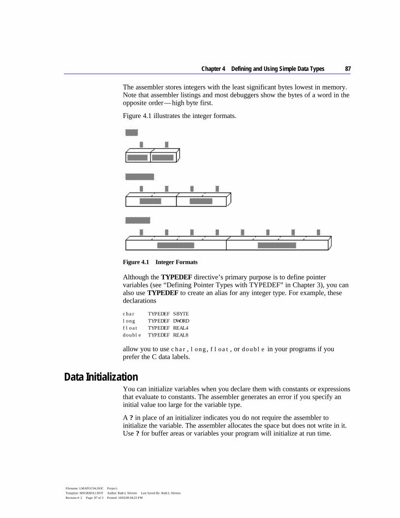
Chapter 4 Defining and Using Simple Data Types 87
Filename: LMAPGC04.DOC Project: Template: MSGRIDA1.DOT Author: Ruth L Silverio Last Saved By: Ruth L Silverio Revision #: 2 Page: 87 of 3 Printed: 10/02/00 04:23 PM
The assembler stores integers with the least significant bytes lowest in memory. Note that assembler listings and most debuggers show the bytes of a word in the opposite order — high byte first.
Figure 4.1 illustrates the integer formats.
Figure 4.1 Integer Formats
Although the TYPEDEF directive’s primary purpose is to define pointer variables (see “Defining Pointer Types with TYPEDEF” in Chapter 3), you can also use TYPEDEF to create an alias for any integer type. For example, these declarations
char TYPEDEF SBYTE long TYPEDEF DWORD float TYPEDEF REAL4 double TYPEDEF REAL8
allow you to use char, long, float, or double in your programs if you prefer the C data labels.
Data Initialization You can initialize variables when you declare them with constants or expressions that evaluate to constants. The assembler generates an error if you specify an initial value too large for the variable type.
A ? in place of an initializer indicates you do not require the assembler to initialize the variable. The assembler allocates the space but does not write in it. Use ? for buffer areas or variables your program will initialize at run time.
88 Programmer’s Guide
Filename: LMAPGC04.DOC Project: Template: MSGRIDA1.DOT Author: Ruth L Silverio Last Saved By: Ruth L Silverio Revision #: 2 Page: 88 of 4 Printed: 10/02/00 04:23 PM
You can declare and initialize variables in one step with the data directives, as these examples show.
integer BYTE 16 ; Initialize byte to 16 negint SBYTE -16 ; Initialize signed byte to -16 expression WORD 4*3 ; Initialize word to 12 signedexp SWORD 4*3 ; Initialize signed word to 12 empty QWORD ? ; Allocate uninitialized long int BYTE 1,2,3,4,5,6 ; Initialize six unnamed bytes long DWORD 4294967295 ; Initialize doubleword to ; 4,294,967,295 longnum SDWORD -2147433648 ; Initialize signed doubleword ; to -2,147,433,648 tb TBYTE 2345t ; Initialize 10-byte binary number
For information on arrays and on using the DUP operator to allocate initializer lists, see “Arrays and Strings” in Chapter 5.
Working with Simple Variables Once you have declared integer variables in your program, you can use them to copy, move, and sign-extend integer variables in your MASM code. This section shows how to do these operations as well as how to add, subtract, multiply, and divide numbers and do bit-level manipulations with logical, shift, and rotate instructions.
Since MASM instructions require operands to be the same size, you may need to operate on data in a size other than that originally declared. You can do this with the PTR operator. For example, you can use the PTR operator to access the high-order word of a DWORD-size variable. The syntax for the PTR operator is
type PTR expression
where the PTR operator forces expression to be treated as having the type specified. An example of this use is
.DATA num DWORD 0 .CODE mov ax, WORD PTR num[0] ; Loads a word-size value from mov dx, WORD PTR num[2] ; a doubleword variable

Chapter 4 Defining and Using Simple Data Types 89
Filename: LMAPGC04.DOC Project: Template: MSGRIDA1.DOT Author: Ruth L Silverio Last Saved By: Ruth L Silverio Revision #: 2 Page: 89 of 5 Printed: 10/02/00 04:23 PM
Copying Data The primary instructions for moving data from operand to operand and loading them into registers are MOV (Move), XCHG (Exchange), CWD (Convert Word to Double), and CBW (Convert Byte to Word).
Moving Data The most common method of moving data, the MOV instruction, is essentially a copy instruction, since it always copies the source operand to the destination operand without affecting the source. After a MOV instruction, the source and destination operands contain the same value.
The following example illustrates the MOV instruction. As explained in “General-Purpose Registers,” Chapter 1, you cannot move a value from one location in memory to another in a single operation.
; Immediate value moves mov ax, 7 ; Immediate to register mov mem, 7 ; Immediate to memory direct mov mem[bx], 7 ; Immediate to memory indirect ; Register moves mov mem, ax ; Register to memory direct mov mem[bx], ax ; Register to memory indirect mov ax, bx ; Register to register mov ds, ax ; General register to segment register ; Direct memory moves mov ax, mem ; Memory direct to register mov ds, mem ; Memory to segment register ; Indirect memory moves mov ax, mem[bx] ; Memory indirect to register mov ds, mem[bx] ; Memory indirect to segment register ; Segment register moves mov mem, ds ; Segment register to memory mov mem[bx], ds ; Segment register to memory indirect mov ax, ds ; Segment register to general register

90 Programmer’s Guide
Filename: LMAPGC04.DOC Project: Template: MSGRIDA1.DOT Author: Ruth L Silverio Last Saved By: Ruth L Silverio Revision #: 2 Page: 90 of 6 Printed: 10/02/00 04:23 PM
The following example shows several common types of moves that require two instructions.
; Move immediate to segment register mov ax, DGROUP ; Load AX with immediate value mov ds, ax ; Copy AX to segment register ; Move memory to memory mov ax, mem1 ; Load AX with memory value mov mem2, ax ; Copy AX to other memory ; Move segment register to segment register mov ax, ds ; Load AX with segment register mov es, ax ; Copy AX to segment register
The MOVSX and MOVZX instructions for the 80386/486 processors extend and copy values in one step. See “Extending Signed and Unsigned Integers,” following.
Exchanging Integers The XCHG (Exchange) instruction exchanges the data in the source and destination operands. You can exchange data between registers or between registers and memory, but not from memory to memory:
xchg ax, bx ; Put AX in BX and BX in AX xchg memory, ax ; Put "memory" in AX and AX in "memory" ; xchg mem1, mem2 ; Illegal- can't exchange memory locations
Extending Signed and Unsigned Integers Since moving data between registers of different sizes is illegal, you must “sign-extend” integers to convert signed data to a larger size. Sign-extending means copying the sign bit of the unextended operand to all bits of the operand’s next larger size. This widens the operand while maintaining its sign and value.
8086-based processors provide four instructions specifically for sign-extending. The four instructions act only on the accumulator register (AL, AX, or EAX), as shown in the following list.
Instruction Sign-extend
CBW (convert byte to word) AL to AX CWD (convert word to doubleword) AX to DX:AX CWDE (convert word to doubleword extended)* AX to EAX CDQ (convert doubleword to quadword)* EAX to EDX:EAX *Requires an extended register and applies only to 80386/486 processors.
Chapter 4 Defining and Using Simple Data Types 91
Filename: LMAPGC04.DOC Project: Template: MSGRIDA1.DOT Author: Ruth L Silverio Last Saved By: Ruth L Silverio Revision #: 2 Page: 91 of 7 Printed: 10/02/00 04:23 PM
On the 80386/486 processors, the CWDE instruction converts a signed 16-bit value in AX to a signed 32-bit value in EAX. The CDQ instruction converts a signed 32-bit value in EAX to a signed 64-bit value in the EDX:EAX register pair.
This example converts signed integers using CBW, CWD, CWDE, and CDQ.
.DATA mem8 SBYTE -5 mem16 SWORD +5 mem32 SDWORD -5 .CODE . . . mov al, mem8 ; Load 8-bit -5 (FBh) cbw ; Convert to 16-bit -5 (FFFBh) in AX mov ax, mem16 ; Load 16-bit +5 cwd ; Convert to 32-bit +5 (0000:0005h) in DX:AX mov ax, mem16 ; Load 16-bit +5 cwde ; Convert to 32-bit +5 (00000005h) in EAX mov eax, mem32 ; Load 32-bit -5 (FFFFFFFBh) cdq ; Convert to 64-bit -5 ; (FFFFFFFF:FFFFFFFBh) in EDX:EAX
These four instructions efficiently convert unsigned values as well, provided the sign bit is zero. This example, for instance, correctly widens mem16 whether you treat the variable as signed or unsigned.
The processor does not differentiate between signed and unsigned values. For instance, the value of mem8 in the previous example is literally 251 (0FBh) to the processor. It ignores the human convention of treating the highest bit as an indicator of sign. The processor can ignore the distinction between signed and unsigned numbers because binary arithmetic works the same in either case.
If you add 7 to mem8, for example, the result is 258 (102h), a value too large to fit into a single byte. The byte-sized mem8 can accommodate only the least-significant digits of the result (02h), and so receives the value of 2. The result is the same whether we treat mem8 as a signed value (-5) or unsigned value (251).
This overview illustrates how the programmer, not the processor, must keep track of which values are signed or unsigned, and treat them accordingly. If AL=127 (01111111y), the instruction CBW sets AX=127 because the sign bit is zero. If AL=128 (10000000y), however, the sign bit is 1. CBW thus sets AX=65,280

92 Programmer’s Guide
Filename: LMAPGC04.DOC Project: Template: MSGRIDA1.DOT Author: Ruth L Silverio Last Saved By: Ruth L Silverio Revision #: 2 Page: 92 of 8 Printed: 10/02/00 04:23 PM
(FF00h), which may not be what you had in mind if you assumed AL originally held an unsigned value.To widen unsigned values, explicitly set the higher register to zero, as shown in the following example:
.DATA mem8 BYTE 251 mem16 WORD 251 .CODE . . . mov al, mem8 ; Load 251 (FBh) from 8-bit memory sub ah, ah ; Zero upper half (AH) mov ax, mem16 ; Load 251 (FBh) from 16-bit memory sub dx, dx ; Zero upper half (DX) sub eax, eax ; Zero entire extended register (EAX) mov ax, mem16 ; Load 251 (FBh) from 16-bit memory
The 80386/486 processors provide instructions that move and extend a value to a larger data size in a single step. MOVSX moves a signed value into a register and sign-extends it. MOVZX moves an unsigned value into a register and zero- extends it.
; 80386/486 instructions movzx dx, bl ; Load unsigned 8-bit value into ; 16-bit register and zero-extend
These special 80386/486 instructions usually execute much faster than the equivalent 8086/286 instructions.
Adding and Subtracting Integers You can use the ADD, ADC, INC, SUB, SBB, and DEC instructions for adding, incrementing, subtracting, and decrementing values in single registers. You can also combine them to handle larger values that require two registers for storage.
Adding and Subtracting Integers Directly The ADD, INC (Increment), SUB, and DEC (Decrement) instructions operate on 8- and 16-bit values on the 8086–80286 processors, and on 8-, 16-, and 32-bit values on the 80386/486 processors. They can be combined with the ADC and SBB instructions to work on 32-bit values on the 8086 and 64-bit values on the 80386/486 processors. (See “Adding and Subtracting in Multiple Registers,” following.)
Chapter 4 Defining and Using Simple Data Types 93
Filename: LMAPGC04.DOC Project: Template: MSGRIDA1.DOT Author: Ruth L Silverio Last Saved By: Ruth L Silverio Revision #: 2 Page: 93 of 9 Printed: 10/02/00 04:23 PM
These instructions have two requirements:
1. If there are two operands, only one operand can be a memory operand. 2. If there are two operands, both must be the same size.
To meet the second requirement, you can use the PTR operator to force an operand to the size required. (See “Working with Simple Variables,” previous.) For example, if Buffer is an array of bytes and BX points to an element of the array, you can add a word from Buffer with
add ax, WORD PTR Buffer[bx] ; Add word from byte array
The next example shows 8-bit signed and unsigned addition and subtraction.
.DATA mem8 BYTE 39 .CODE ; Addition ; signed unsigned mov al, 26 ; Start with register 26 26 inc al ; Increment 1 1 add al, 76 ; Add immediate 76 + 76 ; ---- ---- ; 103 103 add al, mem8 ; Add memory 39 + 39 ; ---- ---- mov ah, al ; Copy to AH -114 142 +overflow add al, ah ; Add register 142 ; ---- ; 28+carry ; Subtraction ; signed unsigned mov al, 95 ; Load register 95 95 dec al ; Decrement -1 -1 sub al, 23 ; Subtract immediate -23 -23 ; ---- ---- ; 71 71 sub al, mem8 ; Subtract memory -122 -122 ; ---- ---- ; -51 205+sign mov ah, 119 ; Load register 119 sub al, ah ; and subtract -51 ; ---- ; 86+overflow

94 Programmer’s Guide
Filename: LMAPGC04.DOC Project: Template: MSGRIDA1.DOT Author: Ruth L Silverio Last Saved By: Ruth L Silverio Revision #: 2 Page: 94 of 10 Printed: 10/02/00 04:23 PM
The INC and DEC instructions treat integers as unsigned values and do not update the carry flag for signed carries and borrows.
When the sum of 8-bit signed operands exceeds 127, the processor sets the overflow flag. (The overflow flag is also set if both operands are negative and the sum is less than or equal to -128.) Placing a JO (Jump on Overflow) or INTO (Interrupt on Overflow) instruction in your program at this point can transfer control to error-recovery statements. When the sum exceeds 255, the processor sets the carry flag. A JC (Jump on Carry) instruction at this point can transfer control to error-recovery statements.
In the previous subtraction example, the processor sets the sign flag if the result goes below 0. At this point, you can use a JS (Jump on Sign) instruction to transfer control to error-recovery statements. Jump instructions are described in the “Jumps” section in Chapter 7.
Adding and Subtracting in Multiple Registers You can add and subtract numbers larger than the register size on your processor with the ADC (Add with Carry) and SBB (Subtract with Borrow) instructions. If the operations prior to an ADC or SBB instruction do not set the carry flag, these instructions are identical to ADD and SUB. When you operate on large values in more than one register, use ADD and SUB for the least significant part of the number and ADC or SBB for the most significant part.
The following example illustrates multiple-register addition and subtraction. You can also use this technique with 64-bit operands on the 80386/486 processors.
.DATA mem32 DWORD 316423 mem32a DWORD 316423 mem32b DWORD 156739 .CODE . . . ; Addition mov ax, 43981 ; Load immediate 43981 sub dx, dx ; into DX:AX add ax, WORD PTR mem32[0] ; Add to both + 316423 adc dx, WORD PTR mem32[2] ; memory words ------ ; Result in DX:AX 360404 ; Subtraction mov ax, WORD PTR mem32a[0] ; Load mem32 316423 mov dx, WORD PTR mem32a[2] ; into DX:AX sub ax, WORD PTR mem32b[0] ; Subtract low - 156739 sbb dx, WORD PTR mem32b[2] ; then high ------ ; Result in DX:AX 159684

Chapter 4 Defining and Using Simple Data Types 95
Filename: LMAPGC04.DOC Project: Template: MSGRIDA1.DOT Author: Ruth L Silverio Last Saved By: Ruth L Silverio Revision #: 2 Page: 95 of 11 Printed: 10/02/00 04:23 PM
For 32-bit registers on the 80386/486 processors, only two steps are necessary. If your program needs to be assembled for more than one processor, you can assemble the statements conditionally, as shown in this example:
.DATA mem32 DWORD 316423 mem32a DWORD 316423 mem32b DWORD 156739 p386 TEXTEQU (@Cpu AND 08h) .CODE . . . ; Addition IF p386 mov eax, 43981 ; Load immediate add eax, mem32 ; Result in EAX ELSE . . ; do steps in previous example . ENDIF ; Subtraction IF p386 mov eax, mem32a ; Load memory sub eax, mem32b ; Result in EAX ELSE . . ; do steps in previous example . ENDIF
Since the status of the carry flag affects the results of calculations with ADC and SBB, be sure to turn off the carry flag with the CLC (Clear Carry Flag) instruction or use ADD or SUB for the first calculation, when appropriate.
Multiplying and Dividing Integers The 8086 family of processors uses different multiplication and division instructions for signed and unsigned integers. Multiplication and division instructions also have special requirements depending on the size of the operands and the processor the code runs on.
Using Multiplication Instructions The MUL instruction multiplies unsigned numbers. IMUL multiplies signed numbers. For both instructions, one factor must be in the accumulator register (AL for 8-bit numbers, AX for 16-bit numbers, EAX for 32-bit numbers). The

96 Programmer’s Guide
Filename: LMAPGC04.DOC Project: Template: MSGRIDA1.DOT Author: Ruth L Silverio Last Saved By: Ruth L Silverio Revision #: 2 Page: 96 of 12 Printed: 10/02/00 04:23 PM
other factor can be in any single register or memory operand. The result overwrites the contents of the accumulator register.
Multiplying two 8-bit numbers produces a 16-bit result returned in AX. Multiplying two 16-bit operands yields a 32-bit result in DX:AX. The 80386/486 processor handles 64-bit products in the same way in the EDX:EAX pair.
This example illustrates multiplication of signed 16- and 32-bit integers.
.DATA mem16 SWORD -30000 .CODE . . . ; 8-bit unsigned multiply mov al, 23 ; Load AL 23 mov bl, 24 ; Load BL * 24 mul bl ; Multiply BL ----- ; Product in AX 552 ; overflow and carry set ; 16-bit signed multiply mov ax, 50 ; Load AX 50 ; -30000 imul mem16 ; Multiply memory ----- ; Product in DX:AX -1500000 ; overflow and carry set
A nonzero number in the upper half of the result (AH for byte, DX or EDX for word) sets the overflow and carry flags.
On the 80186–80486 processors, the IMUL instruction supports three additional operand combinations. The first syntax option allows for 16-bit multipliers producing a 16-bit product or 32-bit multipliers for 32-bit products on the 80386/486. The result overwrites the destination. The syntax for this operation is:
IMUL register16, immediate
The second syntax option specifies three operands for IMUL. The first operand must be a 16-bit register operand, the second a 16-bit memory (or register) operand, and the third a 16-bit immediate operand. IMUL multiplies the memory (or register) and immediate operands and stores the product in the register operand with this syntax:
IMUL register16,{ memory16 | register16}, immediate
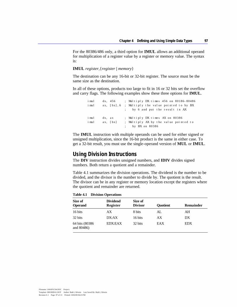
Chapter 4 Defining and Using Simple Data Types 97
Filename: LMAPGC04.DOC Project: Template: MSGRIDA1.DOT Author: Ruth L Silverio Last Saved By: Ruth L Silverio Revision #: 2 Page: 97 of 13 Printed: 10/02/00 04:23 PM
For the 80386/486 only, a third option for IMUL allows an additional operand for multiplication of a register value by a register or memory value. The syntax is:
IMUL register,{register | memory}
The destination can be any 16-bit or 32-bit register. The source must be the same size as the destination.
In all of these options, products too large to fit in 16 or 32 bits set the overflow and carry flags. The following examples show these three options for IMUL.
imul dx, 456 ; Multiply DX times 456 on 80186-80486 imul ax, [bx],6 ; Multiply the value pointed to by BX ; by 6 and put the result in AX imul dx, ax ; Multiply DX times AX on 80386 imul ax, [bx] ; Multiply AX by the value pointed to ; by BX on 80386
The IMUL instruction with multiple operands can be used for either signed or unsigned multiplication, since the 16-bit product is the same in either case. To get a 32-bit result, you must use the single-operand version of MUL or IMUL.
Using Division Instructions The DIV instruction divides unsigned numbers, and IDIV divides signed numbers. Both return a quotient and a remainder.
Table 4.1 summarizes the division operations. The dividend is the number to be divided, and the divisor is the number to divide by. The quotient is the result. The divisor can be in any register or memory location except the registers where the quotient and remainder are returned.
Table 4.1 Division Operations
Size of Operand
Dividend Register
Size of Divisor
Quotient
Remainder
16 bits AX 8 bits AL AH 32 bits DX:AX 16 bits AX DX 64 bits (80386 and 80486)
EDX:EAX 32 bits EAX EDX
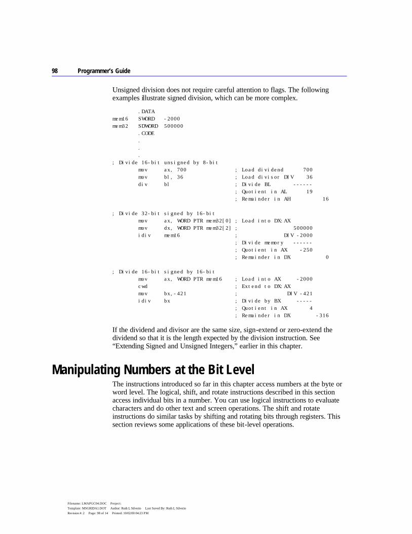
98 Programmer’s Guide
Filename: LMAPGC04.DOC Project: Template: MSGRIDA1.DOT Author: Ruth L Silverio Last Saved By: Ruth L Silverio Revision #: 2 Page: 98 of 14 Printed: 10/02/00 04:23 PM
Unsigned division does not require careful attention to flags. The following examples illustrate signed division, which can be more complex.
.DATA mem16 SWORD -2000 mem32 SDWORD 500000 .CODE . . . ; Divide 16-bit unsigned by 8-bit mov ax, 700 ; Load dividend 700 mov bl, 36 ; Load divisor DIV 36 div bl ; Divide BL ------ ; Quotient in AL 19 ; Remainder in AH 16 ; Divide 32-bit signed by 16-bit mov ax, WORD PTR mem32[0] ; Load into DX:AX mov dx, WORD PTR mem32[2] ; 500000 idiv mem16 ; DIV -2000 ; Divide memory ------ ; Quotient in AX -250 ; Remainder in DX 0 ; Divide 16-bit signed by 16-bit mov ax, WORD PTR mem16 ; Load into AX -2000 cwd ; Extend to DX:AX mov bx,-421 ; DIV -421 idiv bx ; Divide by BX ----- ; Quotient in AX 4 ; Remainder in DX -316
If the dividend and divisor are the same size, sign-extend or zero-extend the dividend so that it is the length expected by the division instruction. See “Extending Signed and Unsigned Integers,” earlier in this chapter.
Manipulating Numbers at the Bit Level The instructions introduced so far in this chapter access numbers at the byte or word level. The logical, shift, and rotate instructions described in this section access individual bits in a number. You can use logical instructions to evaluate characters and do other text and screen operations. The shift and rotate instructions do similar tasks by shifting and rotating bits through registers. This section reviews some applications of these bit-level operations.
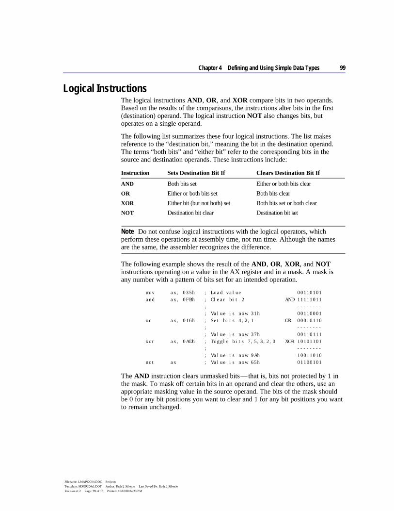
Chapter 4 Defining and Using Simple Data Types 99
Filename: LMAPGC04.DOC Project: Template: MSGRIDA1.DOT Author: Ruth L Silverio Last Saved By: Ruth L Silverio Revision #: 2 Page: 99 of 15 Printed: 10/02/00 04:23 PM
Logical Instructions The logical instructions AND, OR, and XOR compare bits in two operands. Based on the results of the comparisons, the instructions alter bits in the first (destination) operand. The logical instruction NOT also changes bits, but operates on a single operand.
The following list summarizes these four logical instructions. The list makes reference to the “destination bit,” meaning the bit in the destination operand. The terms “both bits” and “either bit” refer to the corresponding bits in the source and destination operands. These instructions include:
Instruction Sets Destination Bit If Clears Destination Bit If
AND Both bits set Either or both bits clear OR Either or both bits set Both bits clear XOR Either bit (but not both) set Both bits set or both clear NOT Destination bit clear Destination bit set
Do not confuse logical instructions with the logical operators, which perform these operations at assembly time, not run time. Although the names are the same, the assembler recognizes the difference.
The following example shows the result of the AND, OR, XOR, and NOT instructions operating on a value in the AX register and in a mask. A mask is any number with a pattern of bits set for an intended operation.
mov ax, 035h ; Load value 00110101 and ax, 0FBh ; Clear bit 2 AND 11111011 ; -------- ; Value is now 31h 00110001 or ax, 016h ; Set bits 4,2,1 OR 00010110 ; -------- ; Value is now 37h 00110111 xor ax, 0ADh ; Toggle bits 7,5,3,2,0 XOR 10101101 ; -------- ; Value is now 9Ah 10011010 not ax ; Value is now 65h 01100101
The AND instruction clears unmasked bits — that is, bits not protected by 1 in the mask. To mask off certain bits in an operand and clear the others, use an appropriate masking value in the source operand. The bits of the mask should be 0 for any bit positions you want to clear and 1 for any bit positions you want to remain unchanged.
Note
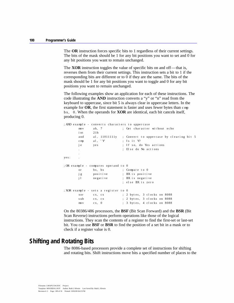
100 Programmer’s Guide
Filename: LMAPGC04.DOC Project: Template: MSGRIDA1.DOT Author: Ruth L Silverio Last Saved By: Ruth L Silverio Revision #: 2 Page: 100 of 16 Printed: 10/02/00 04:23 PM
The OR instruction forces specific bits to 1 regardless of their current settings. The bits of the mask should be 1 for any bit positions you want to set and 0 for any bit positions you want to remain unchanged.
The XOR instruction toggles the value of specific bits on and off — that is, reverses them from their current settings. This instruction sets a bit to 1 if the corresponding bits are different or to 0 if they are the same. The bits of the mask should be 1 for any bit positions you want to toggle and 0 for any bit positions you want to remain unchanged.
The following examples show an application for each of these instructions. The code illustrating the AND instruction converts a “y” or “n” read from the keyboard to uppercase, since bit 5 is always clear in uppercase letters. In the example for OR, the first statement is faster and uses fewer bytes than cmp bx, 0. When the operands for XOR are identical, each bit cancels itself, producing 0.
;AND example - converts characters to uppercase mov ah, 7 ; Get character without echo int 21h and al, 11011111y ; Convert to uppercase by clearing bit 5 cmp al, 'Y' ; Is it Y? je yes ; If so, do Yes actions . ; Else do No actions . yes: . ;OR example - compares operand to 0 or bx, bx ; Compare to 0 jg positive ; BX is positive jl negative ; BX is negative ; else BX is zero ;XOR example - sets a register to 0 xor cx, cx ; 2 bytes, 3 clocks on 8088 sub cx, cx ; 2 bytes, 3 clocks on 8088 mov cx, 0 ; 3 bytes, 4 clocks on 8088
On the 80386/486 processors, the BSF (Bit Scan Forward) and the BSR (Bit Scan Reverse) instructions perform operations like those of the logical instructions. They scan the contents of a register to find the first-set or last-set bit. You can use BSF or BSR to find the position of a set bit in a mask or to check if a register value is 0.
Shifting and Rotating Bits The 8086-based processors provide a complete set of instructions for shifting and rotating bits. Shift instructions move bits a specified number of places to the
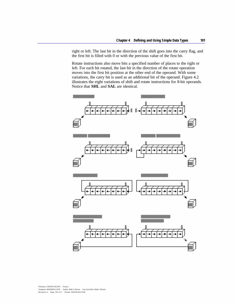
Chapter 4 Defining and Using Simple Data Types 101
Filename: LMAPGC04.DOC Project: Template: MSGRIDA1.DOT Author: Ruth L Silverio Last Saved By: Ruth L Silverio Revision #: 2 Page: 101 of 17 Printed: 10/02/00 04:23 PM
right or left. The last bit in the direction of the shift goes into the carry flag, and the first bit is filled with 0 or with the previous value of the first bit.
Rotate instructions also move bits a specified number of places to the right or left. For each bit rotated, the last bit in the direction of the rotate operation moves into the first bit position at the other end of the operand. With some variations, the carry bit is used as an additional bit of the operand. Figure 4.2 illustrates the eight variations of shift and rotate instructions for 8-bit operands. Notice that SHL and SAL are identical.

102 Programmer’s Guide
Filename: LMAPGC04.DOC Project: Template: MSGRIDA1.DOT Author: Ruth L Silverio Last Saved By: Ruth L Silverio Revision #: 2 Page: 102 of 18 Printed: 10/02/00 04:23 PM
Figure 4.2 Shifts and Rotates
All shift instructions use the same format. Before the instruction executes, the destination operand contains the value to be shifted; after the instruction executes, it contains the shifted operand. The source operand contains the number of bits to shift or rotate. It can be the immediate value 1 or the CL register. The 8088 and 8086 processors do not accept any other values or registers with these instructions.
Starting with the 80186 processor, you can use 8-bit immediate values larger than 1 as the source operand for shift or rotate instructions, as shown here:
shr bx, 4 ; 9 clocks, 3 bytes on 80286
The following statements are equivalent if the program must run on the 8088 or 8086 processor:
mov cl, 4 ; 2 clocks, 3 bytes on 80286 shr bx, cl ; 9 clocks, 2 bytes on 80286 ; 11 clocks, 5 bytes total
Masks for logical instructions can be shifted to new bit positions. For example, an operand that masks off a bit or group of bits can be shifted to move the mask to a different position, allowing you to mask off a different bit each time the mask is used. This technique, illustrated in the following example, is useful only if the mask value is unknown until run time.
.DATA masker BYTE 00000010y ; Mask that may change at run time .CODE . . . mov cl, 2 ; Rotate two at a time mov bl, 57h ; Load value to be changed 01010111y rol masker, cl ; Rotate two to left 00001000y or bl, masker ; Turn on masked values --------- ; New value is 05Fh 01011111y rol masker, cl ; Rotate two more 00100000y or bl, masker ; Turn on masked values --------- ; New value is 07Fh 01111111y
Multiplying and Dividing with Shift Instructions You can use the shift and rotate instructions (SHR, SHL, SAR, and SAL) for multiplication and division. Shifting a value right by one bit has the effect of dividing by two; shifting left by 1 bit has the effect of multiplying by two. You can take advantage of shifts to do fast multiplication and division by powers of
Chapter 4 Defining and Using Simple Data Types 103
Filename: LMAPGC04.DOC Project: Template: MSGRIDA1.DOT Author: Ruth L Silverio Last Saved By: Ruth L Silverio Revision #: 2 Page: 103 of 19 Printed: 10/02/00 04:23 PM
two. For example, shifting left twice multiplies by four, shifting left three times multiplies by eight, and so on.
Use SHR (Shift Right) to divide unsigned numbers. You can use SAR (Shift Arithmetic Right) to divide signed numbers, but SAR rounds negative numbers down — IDIV always rounds negative numbers up (toward 0). Division using SAR must adjust for this difference. Multiplication by shifting is the same for signed and unsigned numbers, so you can use either SAL or SHL.
Multiply and divide instructions are relatively slow, particularly on the 8088 and 8086 processors. When multiplying or dividing by a power of two, use shifts to speed operations by a factor of 10 or more. For example, these statements take only four clocks on an 8088 or 8086 processor:
sub ah, ah ; Clear AH shl ax, 1 ; Multiply byte in AL by 2
The following statements produce the same results, but take between 74 and 81 clocks on the 8088 or 8086 processors. The same statements take 15 clocks on the 80286 and between 11 and 16 clocks on the 80386. (For a discussion about instruction timings, see “A Word on Instruction Timings” in the Introduction.)
mov bl, 2 ; Multiply byte in AL by 2 mul bl
As the following macro shows, it’s possible to multiply by any number — in this case, 10 — without resorting to the MUL instruction. However, such a procedure is no more than an interesting arithmetic exercise, since the additional code almost certainly takes more time to execute than a single MUL. You should consider using shifts in your program only when multiplying or dividing by a power of two.
mul_10 MACRO factor ; Factor must be unsigned mov ax, factor ; Load into AX shl ax, 1 ; AX = factor * 2 mov bx, ax ; Save copy in BX shl ax, 1 ; AX = factor * 4 shl ax, 1 ; AX = factor * 8 add ax, bx ; AX = (factor * 8) + (factor * 2) ENDM ; AX = factor * 10
Here’s another macro that divides by 512. In contrast to the previous example, this macro uses little code and operates faster than an equivalent DIV instruction.
104 Programmer’s Guide
Filename: LMAPGC04.DOC Project: Template: MSGRIDA1.DOT Author: Ruth L Silverio Last Saved By: Ruth L Silverio Revision #: 2 Page: 104 of 20 Printed: 10/02/00 04:23 PM
div_512 MACRO dividend ; Dividend must be unsigned mov ax, dividend ; Load into AX shr ax, 1 ; AX = dividend / 2 (unsigned) xchg al, ah ; XCHG is like rotate right 8 ; AL = (dividend / 2) / 256 cbw ; Clear upper byte ENDM ; AX = (dividend / 512)
If you need to shift a value that is too large to fit in one register, you can shift each part separately. The RCR (Register Carry Right) and RCL (Register Carry Left) instructions carry values from the first register to the second by passing the leftmost or rightmost bit through the carry flag.
This example shifts a multiword value.
.DATA mem32 DWORD 500000 .CODE ; Divide 32-bit unsigned by 16 mov cx, 4 ; Shift right 4 500000 again: shr WORD PTR mem32[2], 1 ; Shift into carry DIV 16 rcr WORD PTR mem32[0], 1 ; Rotate carry in ------ loop again ; 31250
Since the carry flag is treated as part of the operand (it’s like using a 9-bit or 17-bit operand), the flag value before the operation is crucial. The carry flag can be adjusted by a previous instruction, but you can also set or clear the flag directly with the CLC (Clear Carry Flag), CMC (Complement Carry Flag), and STC (Set Carry Flag) instructions.
On the 80386 and 80486 processors, an alternate method for multiplying quickly by constants takes advantage of the LEA (Load Effective Address) instruction and the scaling of indirect memory operands. By using a 32-bit value as both the index and the base register in an indirect memory operand, you can multiply by the constants 2, 3, 4, 5, 8, and 9 more quickly than you can by using the MUL instruction. LEA calculates the offset of the source operand and stores it into the destination register, EBX, as this example shows:
lea ebx, [eax*2] ; EBX = 2 * EAX lea ebx, [eax*2+eax] ; EBX = 3 * EAX lea ebx, [eax*4] ; EBX = 4 * EAX lea ebx, [eax*4+eax] ; EBX = 5 * EAX lea ebx, [eax*8] ; EBX = 8 * EAX lea ebx, [eax*8+eax] ; EBX = 9 * EAX
Scaling of 80386 indirect memory operands is reviewed in “Indirect Memory Operands with 32-Bit Registers” in Chapter 3. LEA is introduced in “Loading Addresses into Registers” in Chapter 3.
Chapter 4 Defining and Using Simple Data Types 105
Filename: LMAPGC04.DOC Project: Template: MSGRIDA1.DOT Author: Ruth L Silverio Last Saved By: Ruth L Silverio Revision #: 2 Page: 105 of 21 Printed: 10/02/00 04:23 PM
The next chapter deals with more complex data types — arrays, strings, structures, unions, and records. Many of the operations presented in this chapter can also be applied to the data structures covered in Chapter 5, “Defining and Using Complex Data Types.”
105
Filename: LMAPGC05.DOC Project: Template: MSGRIDA1.DOT Author: Ruth L Silverio Last Saved By: Ruth L Silverio Revision #: 2 Page: 105 of 1 Printed: 10/02/00 04:23 PM
C H A P T E R 5
With the complex data types available in MASM 6.1 — arrays, strings, records, structures, and unions — you can access data as a unit or as individual elements that make up a unit. The individual elements of complex data types are often the integer types discussed in Chapter 4, “Defining and Using Simple Data Types.”
“Arrays and Strings” reviews how to declare, reference, and initialize arrays and strings. This section summarizes the general steps needed to process arrays and strings and describes the MASM instructions for moving, comparing, searching, loading, and storing.
“Structures and Unions” covers similar information for structures and unions: how to declare structure and union types, how to define structure and union variables, and how to reference structures and unions and their fields.
“Records” explains how to declare record types, define record variables, and use record operators.
Arrays and Strings An array is a sequential collection of variables, all of the same size and type, called “elements.” A string is an array of characters. For example, in the string “ABC,” each letter is an element. You can access the elements in an array or string relative to the first element. This section explains how to handle arrays and strings in your programs.
Declaring and Referencing Arrays Array elements occupy memory contiguously, so a program references each element relative to the start of the array. To declare an array, supply a label name, the element type, and a series of initializing values or ? placeholders. The following examples declare the arrays warray and xarray:
warray WORD 1, 2, 3, 4 xarray DWORD 0FFFFFFFFh, 789ABCDEh
Defining and Using Complex Data Types
106 Programmer’s Guide
Filename: LMAPGC05.DOC Project: Template: MSGRIDA1.DOT Author: Ruth L Silverio Last Saved By: Ruth L Silverio Revision #: 2 Page: 106 of 2 Printed: 10/02/00 04:23 PM
Initializer lists of array declarations can span multiple lines. The first initializer must appear on the same line as the data type, all entries must be initialized, and, if you want the array to continue to the new line, the line must end with a comma. These examples show legal multiple-line array declarations:
big BYTE 21, 22, 23, 24, 25, 26, 27, 28 somelist WORD 10, 20, 30
If you do not use the LENGTHOF and SIZEOF operators discussed later in this section, an array may span more than one logical line, although a separate type declaration is needed on each logical line:
var1 BYTE 10, 20, 30 BYTE 40, 50, 60 BYTE 70, 80, 90
The DUP Operator You can also declare an array with the DUP operator. This operator works with any of the data allocation directives described in “Allocating Memory for Integer Variables” in Chapter 4. In the syntax
count DUP (initialvalue [[, initialvalue]]...)
the count value sets the number of times to repeat all values within the parentheses. The initialvalue can be an integer, character constant, or another DUP operator, and must always appear within parentheses. For example, the statement
barray BYTE 5 DUP (1)
allocates the integer 1 five times for a total of 5 bytes.
The following examples show various ways to allocate data elements with the DUP operator:
array DWORD 10 DUP (1) ; 10 doublewords ; initialized to 1 buffer BYTE 256 DUP (?) ; 256-byte buffer masks BYTE 20 DUP (040h, 020h, 04h, 02h) ; 80-byte buffer ; with bit masks three_d DWORD 5 DUP (5 DUP (5 DUP (0))) ; 125 doublewords ; initialized to 0
Chapter 5 Defining and Using Complex Data Types 107
Filename: LMAPGC05.DOC Project: Template: MSGRIDA1.DOT Author: Ruth L Silverio Last Saved By: Ruth L Silverio Revision #: 2 Page: 107 of 3 Printed: 10/02/00 04:23 PM
Referencing Arrays Each element in an array is referenced with an index number, beginning with zero. The array index appears in brackets after the array name, as in
array[9]
Assembly-language indexes differ from indexes in high-level languages, where the index number always corresponds to the element’s position. In C, for example, array[9] references the array’s tenth element, regardless of whether each element is 1 byte or 8 bytes in size.
In assembly language, an element’s index refers to the number of bytes between the element and the start of the array. This distinction can be ignored for arrays of byte-sized elements, since an element’s position number matches its index. For example, defining the array
prime BYTE 1, 3, 5, 7, 11, 13, 17
gives a value of 1 to prime[0], a value of 3 to prime[1], and so forth.
However, in arrays with elements larger than 1 byte, index numbers (except zero) do not correspond to an element’s position. You must multiply an element’s position by its size to determine the element’s index. Thus, for the array
wprime WORD 1, 3, 5, 7, 11, 13, 17
wprime[4] represents the third element (5), which is 4 bytes from the beginning of the array. Similarly, the expression wprime[6] represents the fourth element (7) and wprime[10] represents the sixth element (13).
The following example determines an index at run time. It multiplies the position by two (the size of a word element) by shifting it left:
mov si, cx ; CX holds position number shl si, 1 ; Scale for word referencing mov ax, wprime[si] ; Move element into AX
The offset required to access an array element can be calculated with the following formula:
nth element of array = array[(n-1) * size of element]
Referencing an array element by distance rather than position is not difficult to master, and is actually very consistent with how assembly language works. Recall that a variable name is a symbol that represents the contents of a particular address in memory. Thus, if the array wprime begins at address DS:2400h, the reference wprime[6] means to the processor “the word value contained in the DS segment at offset 2400h-plus-6-bytes.”
108 Programmer’s Guide
Filename: LMAPGC05.DOC Project: Template: MSGRIDA1.DOT Author: Ruth L Silverio Last Saved By: Ruth L Silverio Revision #: 2 Page: 108 of 4 Printed: 10/02/00 04:23 PM
As described in “Direct Memory Operands,” Chapter 3, you can substitute the plus operator (+) for brackets, as in:
wprime[9] wprime+9
Since brackets simply add a number to an address, you don’t need them when referencing the first element. Thus, wprime and wprime[0] both refer to the first element of the array wprime.
If your program runs only on an 80186 processor or higher, you can use the BOUND instruction to verify that an index value is within the bounds of an array. For a description of BOUND, see the Reference.
LENGTHOF, SIZEOF, and TYPE for Arrays When applied to arrays, the LENGTHOF, SIZEOF, and TYPE operators return information about the length and size of the array and about the type of the initializers.
The LENGTHOF operator returns the number of elements in the array. The SIZEOF operator returns the number of bytes used by the initializers in the array definition. TYPE returns the size of the elements of the array. The following examples illustrate these operators:
array WORD 40 DUP (5) larray EQU LENGTHOF array ; 40 elements sarray EQU SIZEOF array ; 80 bytes tarray EQU TYPE array ; 2 bytes per element num DWORD 4, 5, 6, 7, 8, 9, 10, 11 lnum EQU LENGTHOF num ; 8 elements snum EQU SIZEOF num ; 32 bytes tnum EQU TYPE num ; 4 bytes per element warray WORD 40 DUP (40 DUP (5)) len EQU LENGTHOF warray ; 1600 elements siz EQU SIZEOF warray ; 3200 bytes typ EQU TYPE warray ; 2 bytes per element
Declaring and Initializing Strings A string is an array of characters. Initializing a string like "Hello, there" allocates and initializes 1 byte for each character in the string. An initialized string can be no longer than 255 characters.

Chapter 5 Defining and Using Complex Data Types 109
Filename: LMAPGC05.DOC Project: Template: MSGRIDA1.DOT Author: Ruth L Silverio Last Saved By: Ruth L Silverio Revision #: 2 Page: 109 of 5 Printed: 10/02/00 04:23 PM
For data directives other than BYTE, a string may initialize only the first element. The initializer value must fit into the specified size and conform to the expression word size in effect (see “Integer Constants and Constant Expressions” in Chapter 1), as shown in these examples:
wstr WORD "OK" dstr DWORD "DATA" ; Legal under EXPR32 only
As with arrays, string initializers can span multiple lines. The line must end with a comma if you want the string to continue to the next line.
str1 BYTE "This is a long string that does not ", "fit on one line."
You can also have an array of pointers to strings.
PBYTE TYPEDEF PTR BYTE .DATA msg1 BYTE "Operation completed successfully." msg2 BYTE "Unknown command" msg3 BYTE "File not found" pmsg PBYTE msg1 ; pmsg is an array PBBYTE msg2 ; of pointers to PBYTE msg3 ; above messages
Strings must be enclosed in single (') or double (") quotation marks. To put a single quotation mark inside a string enclosed by single quotation marks, use two single quotation marks. Likewise, if you need quotation marks inside a string enclosed by double quotation marks, use two sets. These examples show the various uses of quotation marks:
char BYTE 'a' message BYTE "That's the message." ; That's the message. warn BYTE 'Can''t find file.' ; Can't find file. string BYTE "This ""value"" not found." ; This "value" not found.
You can always use single quotation marks inside a string enclosed by double quotation marks, as the initialization for message shows, and vice versa.
The ? Initializer You do not have to initialize an array. The ? operator lets you allocate space for the array without placing specific values in it. Object files contain records for initialized data. Unspecified space left in the object file means that no records contain initialized data for that address. The actual values stored in arrays allocated with ? depend on certain conditions. The ? initializer is treated as a zero in a DUP statement that contains initializers in addition to the ? initializer. If the ? initializer does not appear in a DUP statement, or if the DUP statement contains only ? initializers, the assembler leaves the allocated space unspecified.
110 Programmer’s Guide
Filename: LMAPGC05.DOC Project: Template: MSGRIDA1.DOT Author: Ruth L Silverio Last Saved By: Ruth L Silverio Revision #: 2 Page: 110 of 6 Printed: 10/02/00 04:23 PM
LENGTHOF, SIZEOF, and TYPE for Strings Because strings are simply arrays of byte elements, the LENGTHOF, SIZEOF, and TYPE operators behave as you would expect, as illustrated in this example:
msg BYTE "This string extends ", "over three ", "lines." lmsg EQU LENGTHOF msg ; 37 elements smsg EQU SIZEOF msg ; 37 bytes tmsg EQU TYPE msg ; 1 byte per element
Processing Strings The 8086-family instruction set has seven string instructions for fast and efficient processing of entire strings and arrays. The term “string” in “string instructions” refers to a sequence of elements, not just character strings. These instructions work directly only on arrays of bytes and words on the 8086–80486 processors, and on arrays of bytes, words, and doublewords on the 80386/486 processors. Processing larger elements must be done indirectly with loops.
The following list gives capsule descriptions of the five instructions discussed in this section.
Instruction Description
MOVS Copies a string from one location to another STOS Stores contents of the accumulator register to a string CMPS Compares one string with another LODS Loads values from a string to the accumulator register SCAS Scans a string for a specified value
All of these instructions use registers in a similar way and have a similar syntax. Most are used with the repeat instruction prefixes REP, REPE (or REPZ), and REPNE (or REPNZ). REPZ is a synonym for REPE (Repeat While Equal) and REPNZ is a synonym for REPNE (Repeat While Not Equal).
This section first explains the general procedures for using all string instructions. It then illustrates each instruction with an example.
Overview of String Instructions The string instructions have specific requirements for the location of strings and the use of registers. To operate on any string, follow these three steps:
1. Set the direction flag to indicate the direction in which you want to process the string. The STD instruction sets the flag, while CLD clears it.
Chapter 5 Defining and Using Complex Data Types 111
Filename: LMAPGC05.DOC Project: Template: MSGRIDA1.DOT Author: Ruth L Silverio Last Saved By: Ruth L Silverio Revision #: 2 Page: 111 of 7 Printed: 10/02/00 04:23 PM
If the direction flag is clear, the string is processed upward (from low addresses to high addresses, which is from left to right through the string). If the direction flag is set, the string is processed downward (from high addresses to low addresses, or from right to left). Under MS-DOS, the direction flag is normally clear if your program has not changed it.
2. Load the number of iterations for the string instruction into the CX register. If you want to process 100 elements in a string, move 100 into CX. If you wish the string instruction to terminate conditionally (for example, during a search when a match is found), load the maximum number of iterations that can be performed without an error.
3. Load the starting offset address of the source string into DS:SI and the starting address of the destination string into ES:DI. Some string instructions take only a destination or source, not both (see Table 5.1). Normally, the segment address of the source string should be DS, but you can use a segment override to specify a different segment for the source operand. You cannot override the segment address for the destination string. Therefore, you may need to change the value of ES. For information on changing segment registers, see “Programming Segmented Addresses” in Chapter 3.
Although you can use a segment override on the source operand, a segment override combined with a repeat prefix can cause problems in certain situations on all processors except the 80386/486. If an interrupt occurs during the string operation, the segment override is lost and the rest of the string operation processes incorrectly. Segment overrides can be used safely when interrupts are turned off or with the 80386/486 processors.
You can adapt these steps to the requirements of any particular string operation. The syntax for the string instructions is:
[[prefix]] CMPS [[segmentregister:]] source, [[ES:]] destination LODS [[segmentregister:]] source [[prefix]] MOVS [[ES:]] destination, [[segmentregister:]] source [[prefix]] SCAS [[ES:]] destination [[prefix]] STOS [[ES:]] destination
Some instructions have special forms for byte, word, or doubleword operands. If you use the form of the instruction that ends in B (BYTE), W (WORD), or D (DWORD) with LODS, SCAS, and STOS, the assembler knows whether the element is in the AL, AX, or EAX register. Therefore, these instruction forms do not require operands.
Note
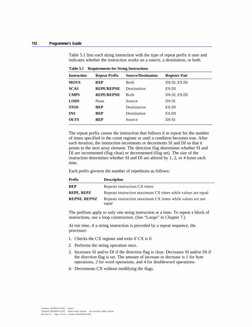
112 Programmer’s Guide
Filename: LMAPGC05.DOC Project: Template: MSGRIDA1.DOT Author: Ruth L Silverio Last Saved By: Ruth L Silverio Revision #: 2 Page: 112 of 8 Printed: 10/02/00 04:23 PM
Table 5.1 lists each string instruction with the type of repeat prefix it uses and indicates whether the instruction works on a source, a destination, or both.
Table 5.1 Requirements for String Instructions
Instruction Repeat Prefix Source/Destination Register Pair
MOVS REP Both DS:SI, ES:DI SCAS REPE/REPNE Destination ES:DI CMPS REPE/REPNE Both DS:SI, ES:DI LODS None Source DS:SI STOS REP Destination ES:DI INS REP Destination ES:DI OUTS REP Source DS:SI
The repeat prefix causes the instruction that follows it to repeat for the number of times specified in the count register or until a condition becomes true. After each iteration, the instruction increments or decrements SI and DI so that it points to the next array element. The direction flag determines whether SI and DI are incremented (flag clear) or decremented (flag set). The size of the instruction determines whether SI and DI are altered by 1, 2, or 4 bytes each time.
Each prefix governs the number of repetitions as follows:
Prefix Description
REP Repeats instruction CX times REPE, REPZ Repeats instruction maximum CX times while values are equal REPNE, REPNZ Repeats instruction maximum CX times while values are not
equal
The prefixes apply to only one string instruction at a time. To repeat a block of instructions, use a loop construction. (See “Loops” in Chapter 7.)
At run time, if a string instruction is preceded by a repeat sequence, the processor:
1. Checks the CX register and exits if CX is 0. 2. Performs the string operation once. 3. Increases SI and/or DI if the direction flag is clear. Decreases SI and/or DI if
the direction flag is set. The amount of increase or decrease is 1 for byte operations, 2 for word operations, and 4 for doubleword operations.
4. Decrements CX without modifying the flags.

Chapter 5 Defining and Using Complex Data Types 113
Filename: LMAPGC05.DOC Project: Template: MSGRIDA1.DOT Author: Ruth L Silverio Last Saved By: Ruth L Silverio Revision #: 2 Page: 113 of 9 Printed: 10/02/00 04:23 PM
5. Checks the zero flag (for SCAS or CMPS) if the REPE or REPNE prefix is used. If the repeat condition holds, loops back to step 1. Otherwise, the loop ends and execution proceeds to the next instruction.
When the repeat loop ends, SI (or DI) points to the position following a match (when using SCAS or CMPS), so you need to decrement or increment DI or SI to point to the element where the last match occurred.
Although string instructions (except LODS) are used most often with repeat prefixes, they can also be used by themselves. In these cases, the SI and/or DI registers are adjusted as specified by the direction flag and the size of operands.
Using String Instructions To use the 8086-family string instructions, follow the steps outlined in the previous section. Examples in this section illustrate each instruction.
You can also use the techniques in this section with structures and unions, since arrays and strings can be fields in structures and unions. (See the section “Structures and Unions,” following.)
Moving Array Data The MOVS instruction copies data from one area of memory to another. To move data, first load the count, source and destination addresses into the appropriate registers. Then use REP with the MOVS instruction.
.MODEL small .DATA source BYTE 10 DUP ('0123456789') destin BYTE 100 DUP (?) .CODE mov ax, @data ; Load same segment mov ds, ax ; to both DS mov es, ax ; and ES . . . cld ; Work upward mov cx, LENGTHOF source ; Set iteration count to 100 mov si, OFFSET source ; Load address of source mov di, OFFSET destin ; Load address of destination rep movsb ; Move 100 bytes
Filling Arrays The STOS instruction stores a specified value in each position of a string. The string is the destination, so it must be pointed to by ES:DI. The value to store must be in the accumulator.

114 Programmer’s Guide
Filename: LMAPGC05.DOC Project: Template: MSGRIDA1.DOT Author: Ruth L Silverio Last Saved By: Ruth L Silverio Revision #: 2 Page: 114 of 10 Printed: 10/02/00 04:23 PM
The next example stores the character 'a' in each byte of a 100-byte string, filling the entire string with “aaaa....” Notice how the code stores 50 words rather than
Chapter 5 Defining and Using Complex Data Types 115
Filename: LMAPGC05.DOC Project: Template: MSGRIDA1.DOT Author: Ruth L Silverio Last Saved By: Ruth L Silverio Revision #: 2 Page: 115 of 11 Printed: 10/02/00 04:23 PM
100 bytes. This makes the fill operation faster by reducing the number of iterations. To fill an odd number of bytes, you need to adjust for the last byte.
.MODEL small, C .DATA destin BYTE 100 DUP (?) ldestin EQU (LENGTHOF destin) / 2 .CODE . ; Assume ES = DS . . cld ; Work upward mov ax, 'aa' ; Load character to fill mov cx, ldestin ; Load length of string mov di, OFFSET destin ; Load address of destination rep stosw ; Store 'aa' into array
Comparing Arrays The CMPS instruction compares two strings and points to the address after which a match or nonmatch occurs. If the values are the same, the zero flag is set. Either string can be considered the destination or the source unless a segment override is used. This example using CMPSB assumes that the strings are in different segments. Both segments must be initialized to the appropriate segment register.
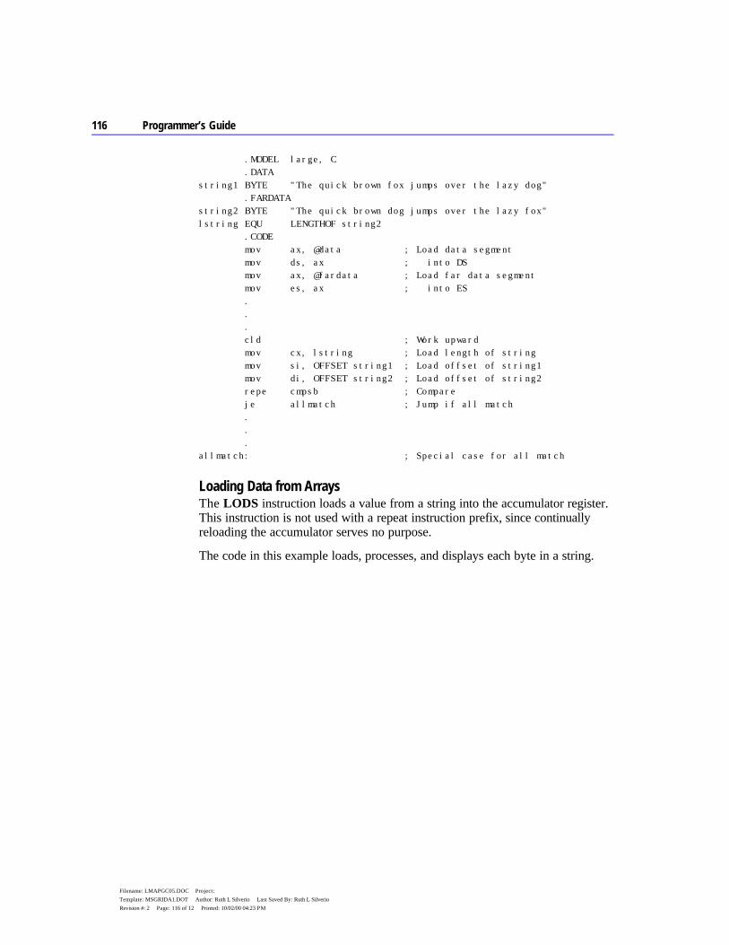
116 Programmer’s Guide
Filename: LMAPGC05.DOC Project: Template: MSGRIDA1.DOT Author: Ruth L Silverio Last Saved By: Ruth L Silverio Revision #: 2 Page: 116 of 12 Printed: 10/02/00 04:23 PM
.MODEL large, C .DATA string1 BYTE "The quick brown fox jumps over the lazy dog" .FARDATA string2 BYTE "The quick brown dog jumps over the lazy fox" lstring EQU LENGTHOF string2 .CODE mov ax, @data ; Load data segment mov ds, ax ; into DS mov ax, @fardata ; Load far data segment mov es, ax ; into ES . . . cld ; Work upward mov cx, lstring ; Load length of string mov si, OFFSET string1 ; Load offset of string1 mov di, OFFSET string2 ; Load offset of string2 repe cmpsb ; Compare je allmatch ; Jump if all match . . . allmatch: ; Special case for all match
Loading Data from Arrays The LODS instruction loads a value from a string into the accumulator register. This instruction is not used with a repeat instruction prefix, since continually reloading the accumulator serves no purpose.
The code in this example loads, processes, and displays each byte in a string.

Chapter 5 Defining and Using Complex Data Types 117
Filename: LMAPGC05.DOC Project: Template: MSGRIDA1.DOT Author: Ruth L Silverio Last Saved By: Ruth L Silverio Revision #: 2 Page: 117 of 13 Printed: 10/02/00 04:23 PM
.DATA info BYTE 0, 1, 2, 3, 4, 5, 6, 7, 8, 9 linfo WORD LENGTHOF info .CODE . . . cld ; Work upward mov cx, linfo ; Load length mov si, OFFSET info ; Load offset of source mov ah, 2 ; Display character function get: lodsb ; Get a character add al, '0' ; Convert to ASCII mov dl, al ; Move to DL int 21h ; Call DOS to display character loop get ; Repeat
Searching Arrays The SCAS instruction compares the value pointed to by ES:DI with the value in the accumulator. If both values are the same, it sets the zero flag.
A repeat prefix lets SCAS work on an entire string, scanning (from which SCAS gets its name) for a particular value called the target. REPNE SCAS sets the zero flag if it finds the target value in the array. REPE SCAS sets the zero flag if the scanned array contains nothing but the target value.
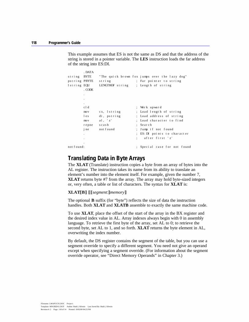
118 Programmer’s Guide
Filename: LMAPGC05.DOC Project: Template: MSGRIDA1.DOT Author: Ruth L Silverio Last Saved By: Ruth L Silverio Revision #: 2 Page: 118 of 14 Printed: 10/02/00 04:23 PM
This example assumes that ES is not the same as DS and that the address of the string is stored in a pointer variable. The LES instruction loads the far address of the string into ES:DI.
.DATA string BYTE "The quick brown fox jumps over the lazy dog" pstring PBYTE string ; Far pointer to string lstring EQU LENGTHOF string ; Length of string .CODE . . . cld ; Work upward mov cx, lstring ; Load length of string les di, pstring ; Load address of string mov al, 'z' ; Load character to find repne scasb ; Search jne notfound ; Jump if not found . ; ES:DI points to character . ; after first 'z' . notfound: ; Special case for not found
Translating Data in Byte Arrays The XLAT (Translate) instruction copies a byte from an array of bytes into the AL register. The instruction takes its name from its ability to translate an element’s number into the element itself. For example, given the number 7, XLAT returns byte #7 from the array. The array may hold byte-sized integers or, very often, a table or list of characters. The syntax for XLAT is:
XLAT[[B]] [[[[segment:]]memory]]
The optional B suffix (for “byte”) reflects the size of data the instruction handles. Both XLAT and XLATB assemble to exactly the same machine code.
To use XLAT, place the offset of the start of the array in the BX register and the desired index value in AL. Array indexes always begin with 0 in assembly language. To retrieve the first byte of the array, set AL to 0; to retrieve the second byte, set AL to 1, and so forth. XLAT returns the byte element in AL, overwriting the index number.
By default, the DS register contains the segment of the table, but you can use a segment override to specify a different segment. You need not give an operand except when specifying a segment override. (For information about the segment override operator, see “Direct Memory Operands” in Chapter 3.)
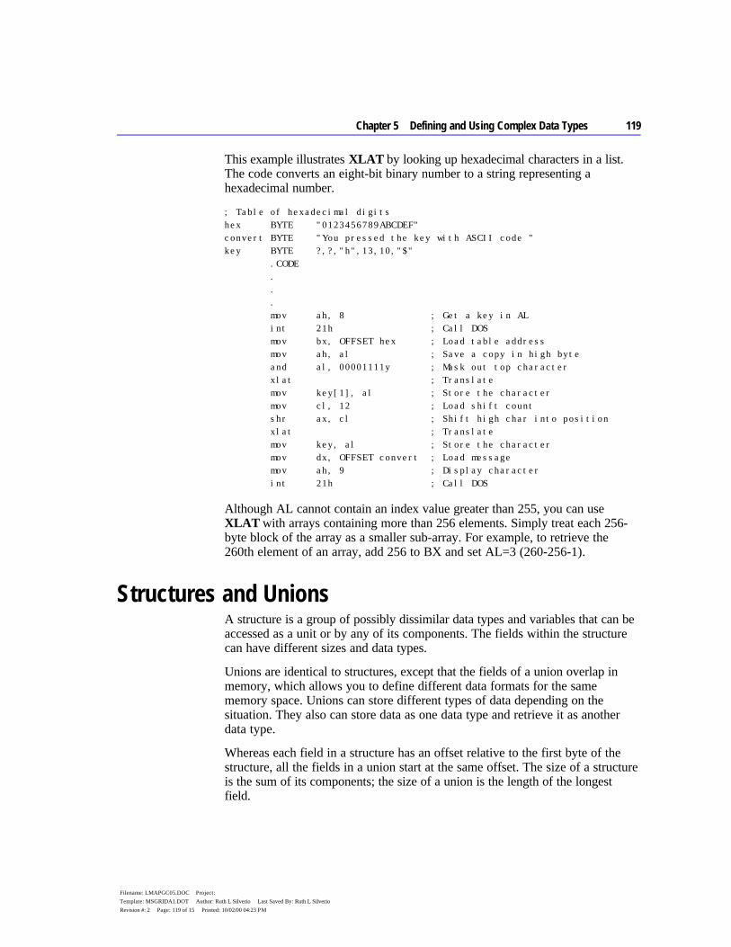
Chapter 5 Defining and Using Complex Data Types 119
Filename: LMAPGC05.DOC Project: Template: MSGRIDA1.DOT Author: Ruth L Silverio Last Saved By: Ruth L Silverio Revision #: 2 Page: 119 of 15 Printed: 10/02/00 04:23 PM
This example illustrates XLAT by looking up hexadecimal characters in a list. The code converts an eight-bit binary number to a string representing a hexadecimal number.
; Table of hexadecimal digits hex BYTE "0123456789ABCDEF" convert BYTE "You pressed the key with ASCII code " key BYTE ?,?,"h",13,10,"$" .CODE . . . mov ah, 8 ; Get a key in AL int 21h ; Call DOS mov bx, OFFSET hex ; Load table address mov ah, al ; Save a copy in high byte and al, 00001111y ; Mask out top character xlat ; Translate mov key[1], al ; Store the character mov cl, 12 ; Load shift count shr ax, cl ; Shift high char into position xlat ; Translate mov key, al ; Store the character mov dx, OFFSET convert ; Load message mov ah, 9 ; Display character int 21h ; Call DOS
Although AL cannot contain an index value greater than 255, you can use XLAT with arrays containing more than 256 elements. Simply treat each 256-byte block of the array as a smaller sub-array. For example, to retrieve the 260th element of an array, add 256 to BX and set AL=3 (260-256-1).
Structures and Unions A structure is a group of possibly dissimilar data types and variables that can be accessed as a unit or by any of its components. The fields within the structure can have different sizes and data types.
Unions are identical to structures, except that the fields of a union overlap in memory, which allows you to define different data formats for the same memory space. Unions can store different types of data depending on the situation. They also can store data as one data type and retrieve it as another data type.
Whereas each field in a structure has an offset relative to the first byte of the structure, all the fields in a union start at the same offset. The size of a structure is the sum of its components; the size of a union is the length of the longest field.
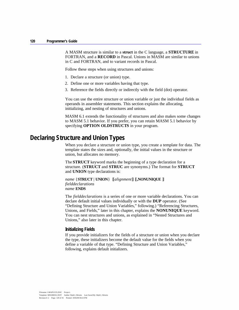
120 Programmer’s Guide
Filename: LMAPGC05.DOC Project: Template: MSGRIDA1.DOT Author: Ruth L Silverio Last Saved By: Ruth L Silverio Revision #: 2 Page: 120 of 16 Printed: 10/02/00 04:23 PM
A MASM structure is similar to a struct in the C language, a STRUCTURE in FORTRAN, and a RECORD in Pascal. Unions in MASM are similar to unions in C and FORTRAN, and to variant records in Pascal.
Follow these steps when using structures and unions:
1. Declare a structure (or union) type. 2. Define one or more variables having that type. 3. Reference the fields directly or indirectly with the field (dot) operator.
You can use the entire structure or union variable or just the individual fields as operands in assembler statements. This section explains the allocating, initializing, and nesting of structures and unions.
MASM 6.1 extends the functionality of structures and also makes some changes to MASM 5.1 behavior. If you prefer, you can retain MASM 5.1 behavior by specifying OPTION OLDSTRUCTS in your program.
Declaring Structure and Union Types When you declare a structure or union type, you create a template for data. The template states the sizes and, optionally, the initial values in the structure or union, but allocates no memory.
The STRUCT keyword marks the beginning of a type declaration for a structure. (STRUCT and STRUC are synonyms.) The format for STRUCT and UNION type declarations is:
name {STRUCT | UNION} [[alignment]] [[,NONUNIQUE ]] fielddeclarations name ENDS
The fielddeclarations is a series of one or more variable declarations. You can declare default initial values individually or with the DUP operator. (See “Defining Structure and Union Variables,” following.) “Referencing Structures, Unions, and Fields,” later in this chapter, explains the NONUNIQUE keyword. You can nest structures and unions, as explained in “Nested Structures and Unions,” also later in this chapter.
Initializing Fields If you provide initializers for the fields of a structure or union when you declare the type, these initializers become the default value for the fields when you define a variable of that type. “Defining Structure and Union Variables,” following, explains default initializers.
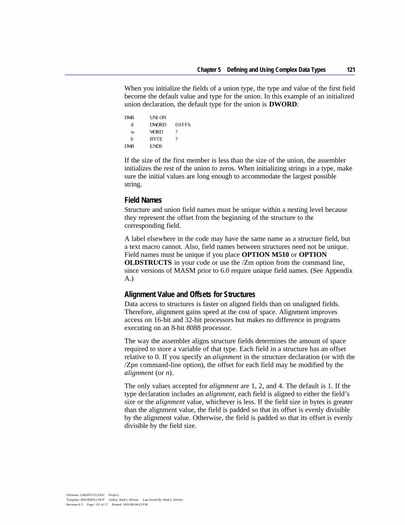
Chapter 5 Defining and Using Complex Data Types 121
Filename: LMAPGC05.DOC Project: Template: MSGRIDA1.DOT Author: Ruth L Silverio Last Saved By: Ruth L Silverio Revision #: 2 Page: 121 of 17 Printed: 10/02/00 04:23 PM
When you initialize the fields of a union type, the type and value of the first field become the default value and type for the union. In this example of an initialized union declaration, the default type for the union is DWORD:
DWB UNION d DWORD 00FFh w WORD ? b BYTE ? DWB ENDS
If the size of the first member is less than the size of the union, the assembler initializes the rest of the union to zeros. When initializing strings in a type, make sure the initial values are long enough to accommodate the largest possible string.
Field Names Structure and union field names must be unique within a nesting level because they represent the offset from the beginning of the structure to the corresponding field.
A label elsewhere in the code may have the same name as a structure field, but a text macro cannot. Also, field names between structures need not be unique. Field names must be unique if you place OPTION M510 or OPTION OLDSTRUCTS in your code or use the /Zm option from the command line, since versions of MASM prior to 6.0 require unique field names. (See Appendix A.)
Alignment Value and Offsets for Structures Data access to structures is faster on aligned fields than on unaligned fields. Therefore, alignment gains speed at the cost of space. Alignment improves access on 16-bit and 32-bit processors but makes no difference in programs executing on an 8-bit 8088 processor.
The way the assembler aligns structure fields determines the amount of space required to store a variable of that type. Each field in a structure has an offset relative to 0. If you specify an alignment in the structure declaration (or with the /Zpn command-line option), the offset for each field may be modified by the alignment (or n).
The only values accepted for alignment are 1, 2, and 4. The default is 1. If the type declaration includes an alignment, each field is aligned to either the field’s size or the alignment value, whichever is less. If the field size in bytes is greater than the alignment value, the field is padded so that its offset is evenly divisible by the alignment value. Otherwise, the field is padded so that its offset is evenly divisible by the field size.

122 Programmer’s Guide
Filename: LMAPGC05.DOC Project: Template: MSGRIDA1.DOT Author: Ruth L Silverio Last Saved By: Ruth L Silverio Revision #: 2 Page: 122 of 18 Printed: 10/02/00 04:23 PM
Any padding required to reach the correct offset for the field is added prior to allocating the field. The padding consists of zeros and always precedes the aligned field. The size of the structure must also be evenly divisible by the structure alignment value, so zeros may be added at the end of the structure.
If neither the alignment nor the /Zp command-line option is used, the offset is incremented by the size of each data directive. This is the same as a default alignment equal to 1. The alignment specified in the type declaration overrides the /Zp command-line option.
These examples show how the assembler determines offsets:
STUDENT2 STRUCT 2 ; Alignment value is 2 score WORD 1 ; Offset = 0 id BYTE 2 ; Offset = 2 (1 byte padding added) year DWORD 3 ; Offset = 4 sname BYTE 4 ; Offset = 8 (1 byte padding added) STUDENT2 ENDS
One byte of padding is added at the end of the first byte-sized field. Otherwise, the offset of the year field would be 3, which is not divisible by the alignment value of 2. The size of this structure is now 9 bytes. Since 9 is not evenly divisible by 2, 1 byte of padding is added at the end of student2.
STUDENT4 STRUCT 4 ; Alignment value is 4 sname BYTE 1 ; Offset = 0 (1 byte padding added) score WORD 10 DUP (100) ; Offset = 2 year BYTE 2 ; Offset = 22 (1 byte padding ; added so offset of next field ; is divisible by 4) id DWORD 3 ; Offset = 24 STUDENT4 ENDS
The alignment value affects the alignment of structure variables, so adding an alignment value affects memory usage. This feature provides compatibility with structures in Microsoft C. MASM 6.1 provides an improved H2INC utility, which C programmers can use to translate C structures to assembly. (See Environment and Tools, Chapter 20.)
The ALIGN, EVEN, and ORG directives can modify how field offsets are placed during structure definition. The EVEN and ALIGN directives insert padding bytes to round the field offset up to the specified alignment boundary. The ORG directive changes the offset of the next field to a given value, either positive or negative. If you use ORG when declaring a structure, you cannot define a structure of that type. ORG is useful when accessing existing data structures, such as a stack frame created by a high-level language.

Chapter 5 Defining and Using Complex Data Types 123
Filename: LMAPGC05.DOC Project: Template: MSGRIDA1.DOT Author: Ruth L Silverio Last Saved By: Ruth L Silverio Revision #: 2 Page: 123 of 19 Printed: 10/02/00 04:23 PM
Defining Structure and Union Variables Once you have declared a structure or union type, you can define variables of that type. For each variable defined, memory is allocated in the current segment in the format declared by the type. The syntax for defining a structure or union variable is:
[[name]] typename < [[initializer [[,initializer]]...]] >
[[name]] typename { [[initializer [[,initializer]]...]] }
[[name]] typename constant DUP ({ [[initializer [[,initializer]]...]] })
The name is the label assigned to the variable. If you do not provide a name, the assembler allocates space for the variable but does not give it a symbolic name. The typename is the name of a previously declared structure or union type.
You can give an initializer for each field. Each initializer must correspond in type with the field defined in the type declaration. For unions, the type of the initializer must be the same as the type for the first field. An initialization list can also use the DUP operator.
The list of initializers can be broken only after a comma unless you end the line with a continuation character (\). The last curly brace or angle bracket must appear on the same line as the last initializer. You can also use the line continuation character to extend a line as shown in the Item4 declaration that follows. Angle brackets and curly braces can be intermixed in an initialization as long as they match. This example illustrates the options for initializing lists in structures of type ITEMS:
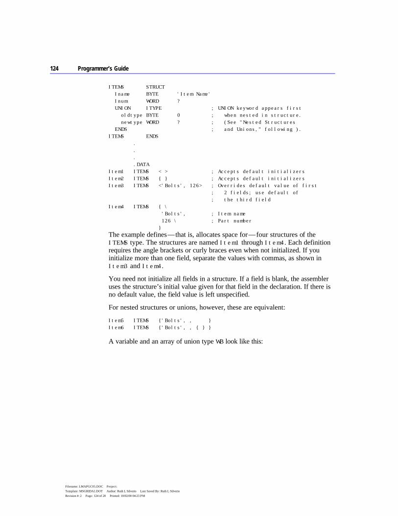
124 Programmer’s Guide
Filename: LMAPGC05.DOC Project: Template: MSGRIDA1.DOT Author: Ruth L Silverio Last Saved By: Ruth L Silverio Revision #: 2 Page: 124 of 20 Printed: 10/02/00 04:23 PM
ITEMS STRUCT Iname BYTE 'Item Name' Inum WORD ? UNION ITYPE ; UNION keyword appears first oldtype BYTE 0 ; when nested in structure. newtype WORD ? ; (See "Nested Structures ENDS ; and Unions," following ). ITEMS ENDS . . . .DATA Item1 ITEMS < > ; Accepts default initializers Item2 ITEMS { } ; Accepts default initializers Item3 ITEMS <'Bolts', 126> ; Overrides default value of first ; 2 fields; use default of ; the third field Item4 ITEMS { \ 'Bolts', ; Item name 126 \ ; Part number }
The example defines — that is, allocates space for — four structures of the ITEMS type. The structures are named Item1 through Item4. Each definition requires the angle brackets or curly braces even when not initialized. If you initialize more than one field, separate the values with commas, as shown in Item3 and Item4.
You need not initialize all fields in a structure. If a field is blank, the assembler uses the structure’s initial value given for that field in the declaration. If there is no default value, the field value is left unspecified.
For nested structures or unions, however, these are equivalent:
Item5 ITEMS {'Bolts', , } Item6 ITEMS {'Bolts', , { } }
A variable and an array of union type WB look like this:

Chapter 5 Defining and Using Complex Data Types 125
Filename: LMAPGC05.DOC Project: Template: MSGRIDA1.DOT Author: Ruth L Silverio Last Saved By: Ruth L Silverio Revision #: 2 Page: 125 of 21 Printed: 10/02/00 04:23 PM
WB UNION w WORD ? b BYTE ? WB ENDS num WB {0Fh} ; Store 0Fh array WB (40 / SIZEOF WB) DUP ({2}) ; Allocates and ; initializes 20 unions
Arrays as Field Initializers The size of the initializer determines the length of the array that can override the contents of a field in a variable definition. The override cannot contain more elements than the default. Specifying fewer override array elements changes the first n values of the default where n is the number of values in the override. The rest of the array elements take their default values from the initializer.
Strings as Field Initializers If the override is shorter, the assembler pads the override with spaces to equal the length of the initializer. If the initializer is a string and the override value is not a string, the override value must be enclosed in angle brackets or curly braces.
A string can override any member of type BYTE (or SBYTE). You need not enclose the string in angle brackets or curly braces unless mixed with other override methods.
If a structure has an initialized string field or an array of bytes, any new string assigned to a variable of the field that is smaller than the default is padded with spaces. The assembler adds four spaces at the end of 'Bolts' in the variables of type ITEMS previously shown. The Iname field in the ITEMS structure cannot contain a field initializer longer than 'Item Name'.
Structures as Field Initializers Initializers for structure variables must be enclosed in curly braces or angle brackets, but you can specify overrides with fewer elements than the defaults.
This example illustrates the use of default values with structures as field initializers:

126 Programmer’s Guide
Filename: LMAPGC05.DOC Project: Template: MSGRIDA1.DOT Author: Ruth L Silverio Last Saved By: Ruth L Silverio Revision #: 2 Page: 126 of 22 Printed: 10/02/00 04:23 PM
DISKDRIVES STRUCT a1 BYTE ? b1 BYTE ? c1 BYTE ? DISKDRIVES ENDS INFO STRUCT buffer BYTE 100 DUP (?) crlf BYTE 13, 10 query BYTE 'Filename: ' ; String <= can override endmark BYTE 36 drives DISKDRIVES <0, 1, 1> INFO ENDS info1 INFO { , , 'Dir' } ; Next line illegal since name in query field is too long: ; info2 INFO {"TESTFILE", , "DirectoryName"} lotsof INFO { , , 'file1', , {0,0,0} }, { , , 'file2', , {0,0,1} }, { , , 'file3', , {0,0,2} }
The following diagram shows how the assembler stores info1.
The initialization for drives gives default values for all three fields of the structure. The fields left blank in info1 use the default values for those fields. The info2 declaration is illegal because “DirectoryName” is longer than the initial string for that field.
Arrays of Structures and Unions You can define an array of structures using the DUP operator (see “Declaring and Referencing Arrays,” earlier in this chapter) or by creating a list of structures. For example, you can define an array of structure variables like this:
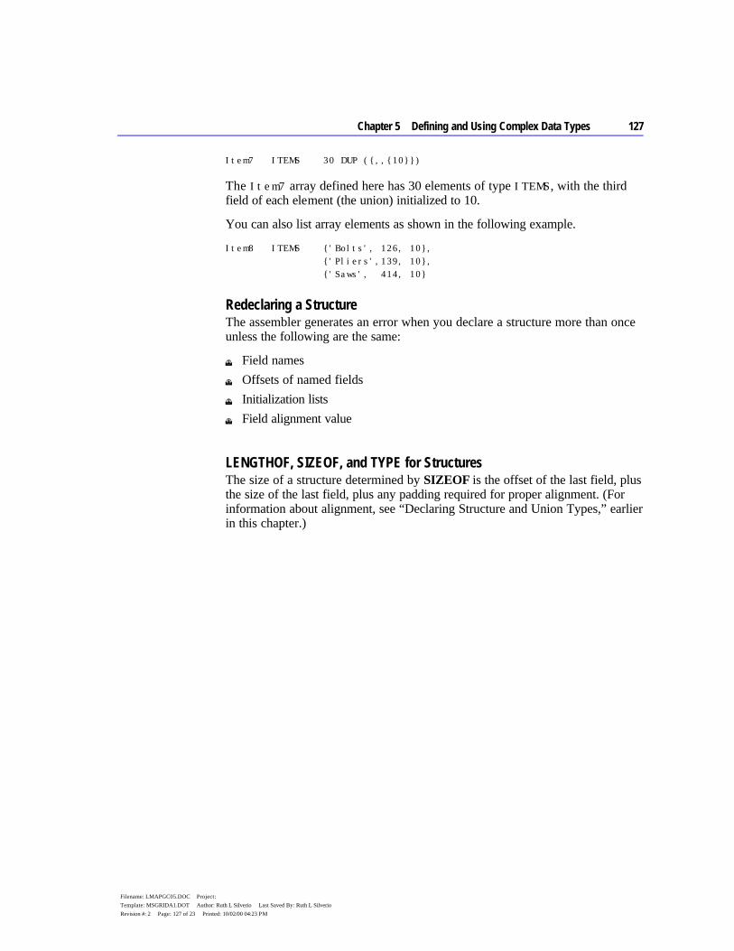
Chapter 5 Defining and Using Complex Data Types 127
Filename: LMAPGC05.DOC Project: Template: MSGRIDA1.DOT Author: Ruth L Silverio Last Saved By: Ruth L Silverio Revision #: 2 Page: 127 of 23 Printed: 10/02/00 04:23 PM
Item7 ITEMS 30 DUP ({,,{10}})
The Item7 array defined here has 30 elements of type ITEMS, with the third field of each element (the union) initialized to 10.
You can also list array elements as shown in the following example.
Item8 ITEMS {'Bolts', 126, 10}, {'Pliers',139, 10}, {'Saws', 414, 10}
Redeclaring a Structure The assembler generates an error when you declare a structure more than once unless the following are the same:
u Field names u Offsets of named fields u Initialization lists u Field alignment value
LENGTHOF, SIZEOF, and TYPE for Structures The size of a structure determined by SIZEOF is the offset of the last field, plus the size of the last field, plus any padding required for proper alignment. (For information about alignment, see “Declaring Structure and Union Types,” earlier in this chapter.)
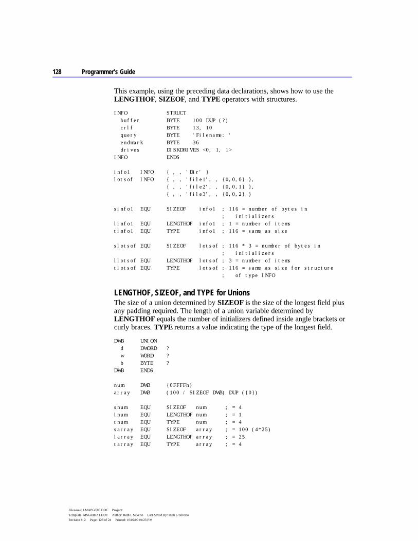
128 Programmer’s Guide
Filename: LMAPGC05.DOC Project: Template: MSGRIDA1.DOT Author: Ruth L Silverio Last Saved By: Ruth L Silverio Revision #: 2 Page: 128 of 24 Printed: 10/02/00 04:23 PM
This example, using the preceding data declarations, shows how to use the LENGTHOF, SIZEOF, and TYPE operators with structures.
INFO STRUCT buffer BYTE 100 DUP (?) crlf BYTE 13, 10 query BYTE 'Filename: ' endmark BYTE 36 drives DISKDRIVES <0, 1, 1> INFO ENDS info1 INFO { , , 'Dir' } lotsof INFO { , , 'file1', , {0,0,0} }, { , , 'file2', , {0,0,1} }, { , , 'file3', , {0,0,2} } sinfo1 EQU SIZEOF info1 ; 116 = number of bytes in ; initializers linfo1 EQU LENGTHOF info1 ; 1 = number of items tinfo1 EQU TYPE info1 ; 116 = same as size slotsof EQU SIZEOF lotsof ; 116 * 3 = number of bytes in ; initializers llotsof EQU LENGTHOF lotsof ; 3 = number of items tlotsof EQU TYPE lotsof ; 116 = same as size for structure ; of type INFO
LENGTHOF, SIZEOF, and TYPE for Unions The size of a union determined by SIZEOF is the size of the longest field plus any padding required. The length of a union variable determined by LENGTHOF equals the number of initializers defined inside angle brackets or curly braces. TYPE returns a value indicating the type of the longest field.
DWB UNION d DWORD ? w WORD ? b BYTE ? DWB ENDS num DWB {0FFFFh} array DWB (100 / SIZEOF DWB) DUP ({0}) snum EQU SIZEOF num ; = 4 lnum EQU LENGTHOF num ; = 1 tnum EQU TYPE num ; = 4 sarray EQU SIZEOF array ; = 100 (4*25) larray EQU LENGTHOF array ; = 25 tarray EQU TYPE array ; = 4
Chapter 5 Defining and Using Complex Data Types 129
Filename: LMAPGC05.DOC Project: Template: MSGRIDA1.DOT Author: Ruth L Silverio Last Saved By: Ruth L Silverio Revision #: 2 Page: 129 of 25 Printed: 10/02/00 04:23 PM
Referencing Structures, Unions, and Fields Like other variables, structure variables can be accessed by name. You can access fields within structure variables with this syntax:
variable. field
References to fields must always be fully qualified, with the structure or union names and the dot operator preceding the field name. The assembler requires that you use the dot operator only with structure fields, not as an alternative to the plus operator; nor can you use the plus operator as an alternative to the dot operator.
The following example shows several ways to reference the fields of a structure of type DATE.
DATE STRUCT ; Defines structure type month BYTE ? day BYTE ? year WORD ? DATE ENDS yesterday DATE {1, 20, 1993} ; Declare structure ; variable . . . mov al, yesterday.day ; Use structure variables mov bx, OFFSET yesterday ; Load structure address mov al, (DATE PTR [bx]).month ; Use as indirect operand mov al, [bx].date.month ; This is necessary only if ; month is already a ; field in a different ; structure
Under OPTION M510 or OPTION OLDSTRUCTS, unique structure names do not need to be qualified. However, if the NONUNIQUE keyword appears in a structure definition, all fields of the structure must be fully qualified when referenced, even if the OPTION OLDSTRUCTS directive appears in the code. Also, you must qualify all references to a field. (For information on the OPTION directive, see Chapter 1.)
Even if the initialized union is the size of a WORD or DWORD, members of structures or unions are accessible only through the field’s names.
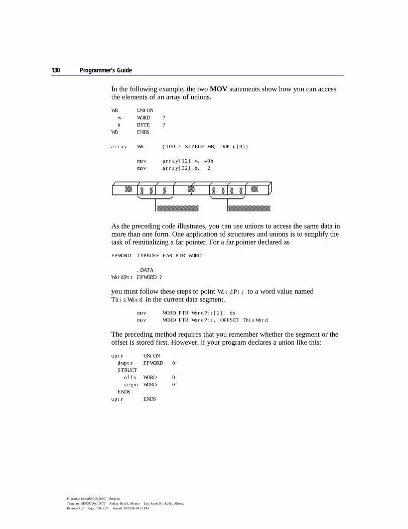
130 Programmer’s Guide
Filename: LMAPGC05.DOC Project: Template: MSGRIDA1.DOT Author: Ruth L Silverio Last Saved By: Ruth L Silverio Revision #: 2 Page: 130 of 26 Printed: 10/02/00 04:23 PM
In the following example, the two MOV statements show how you can access the elements of an array of unions.
WB UNION w WORD ? b BYTE ? WB ENDS array WB (100 / SIZEOF WB) DUP ({0}) mov array[12].w, 40h mov array[32].b, 2
As the preceding code illustrates, you can use unions to access the same data in more than one form. One application of structures and unions is to simplify the task of reinitializing a far pointer. For a far pointer declared as
FPWORD TYPEDEF FAR PTR WORD .DATA WordPtr FPWORD ?
you must follow these steps to point WordPtr to a word value named ThisWord in the current data segment.
mov WORD PTR WordPtr[2], ds mov WORD PTR WordPtr, OFFSET ThisWord
The preceding method requires that you remember whether the segment or the offset is stored first. However, if your program declares a union like this:
uptr UNION dwptr FPWORD 0 STRUCT offs WORD 0 segm WORD 0 ENDS uptr ENDS
Chapter 5 Defining and Using Complex Data Types 131
Filename: LMAPGC05.DOC Project: Template: MSGRIDA1.DOT Author: Ruth L Silverio Last Saved By: Ruth L Silverio Revision #: 2 Page: 131 of 27 Printed: 10/02/00 04:23 PM
You can initialize a far pointer with these steps:
.DATA WrdPtr2 uptr <> . . . mov WrdPtr2.segm, ds mov WrdPtr2.offs, OFFSET ThisWord
This code moves the segment and the offset into the pointer and then moves the pointer into a register with the other field of the union. Although this technique does not reduce the code size, it avoids confusion about the order for loading the segment and offset.
Nested Structures and Unions You can nest structures and unions in several ways. This section explains how to refer to the fields in a nested structure or union. The following example illustrates the four techniques for nesting, and how to reference the fields. Note the syntax for nested structures. The techniques are reviewed following the example.
ITEMS STRUCT Inum WORD ? Iname BYTE 'Item Name' ITEMS ENDS INVENTORY STRUCT UpDate WORD ? oldItem ITEMS { \ 100, 'AF8' \ ; Named variable of } ; existing structure ITEMS { ?, '94C' } ; Unnamed variable of ; existing type STRUCT ups ; Named nested structure source WORD ? shipmode BYTE ? ENDS STRUCT ; Unnamed nested structure f1 WORD ? f2 WORD ? ENDS INVENTORY ENDS .DATA yearly INVENTORY { }
132 Programmer’s Guide
Filename: LMAPGC05.DOC Project: Template: MSGRIDA1.DOT Author: Ruth L Silverio Last Saved By: Ruth L Silverio Revision #: 2 Page: 132 of 28 Printed: 10/02/00 04:23 PM
; Referencing each type of data in the yearly structure: mov ax, yearly.oldItem.Inum mov yearly.ups.shipmode, 'A' mov yearly.Inum, 'C' mov ax, yearly.f1
To nest structures and unions, you can use any of these techniques:
u The field of a structure or union can be a named variable of an existing structure or union type, as in the oldItem field. Because INVENTORY contains two structures of type ITEMS , the field names in oldItem are not unique. Therefore, you must use the full field names when referencing those fields, as in the statement mov ax, yearly.oldItem.Inum
u To declare a named structure or union inside another structure or union, give the STRUCT or UNION keyword first and then define a label for it. Fields of the nested structure or union must always be qualified: mov yearly.ups.shipmode, 'A'
u As shown in the Items field of Inventory, you also can use unnamed variables of existing structures or unions inside another structure or union. In these cases, you can reference fields directly: mov yearly.Inum, 'C' mov ax, yearly.f1
Records Records are similar to structures, except that fields in records are bit strings. Each bit field in a record variable can be used separately in constant operands or expressions. The processor cannot access bits individually at run time, but it can access bit fields with instructions that manipulate bits.
Records are bytes, words, or doublewords in which the individual bits or groups of bits are considered fields. In general, the three steps for using record variables are the same as those for using other complex data types:
1. Declare a record type. 2. Define one or more variables having the record type. 3. Reference record variables using shifts and masks.
Once it is defined, you can use the record variable as an operand in assembler statements.
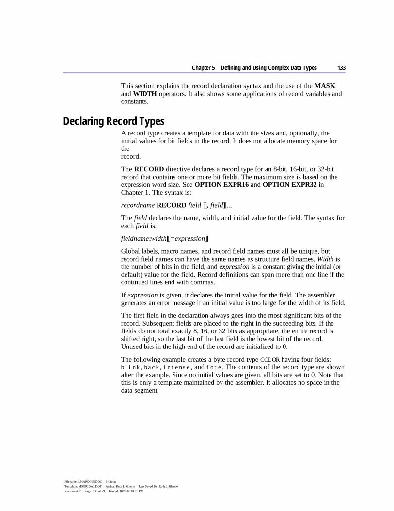
Chapter 5 Defining and Using Complex Data Types 133
Filename: LMAPGC05.DOC Project: Template: MSGRIDA1.DOT Author: Ruth L Silverio Last Saved By: Ruth L Silverio Revision #: 2 Page: 133 of 29 Printed: 10/02/00 04:23 PM
This section explains the record declaration syntax and the use of the MASK and WIDTH operators. It also shows some applications of record variables and constants.
Declaring Record Types A record type creates a template for data with the sizes and, optionally, the initial values for bit fields in the record. It does not allocate memory space for the record.
The RECORD directive declares a record type for an 8-bit, 16-bit, or 32-bit record that contains one or more bit fields. The maximum size is based on the expression word size. See OPTION EXPR16 and OPTION EXPR32 in Chapter 1. The syntax is:
recordname RECORD field [[, field]]...
The field declares the name, width, and initial value for the field. The syntax for each field is:
fieldname:width[[=expression]]
Global labels, macro names, and record field names must all be unique, but record field names can have the same names as structure field names. Width is the number of bits in the field, and expression is a constant giving the initial (or default) value for the field. Record definitions can span more than one line if the continued lines end with commas.
If expression is given, it declares the initial value for the field. The assembler generates an error message if an initial value is too large for the width of its field.
The first field in the declaration always goes into the most significant bits of the record. Subsequent fields are placed to the right in the succeeding bits. If the fields do not total exactly 8, 16, or 32 bits as appropriate, the entire record is shifted right, so the last bit of the last field is the lowest bit of the record. Unused bits in the high end of the record are initialized to 0.
The following example creates a byte record type COLOR having four fields: blink, back, intense, and fore. The contents of the record type are shown after the example. Since no initial values are given, all bits are set to 0. Note that this is only a template maintained by the assembler. It allocates no space in the data segment.
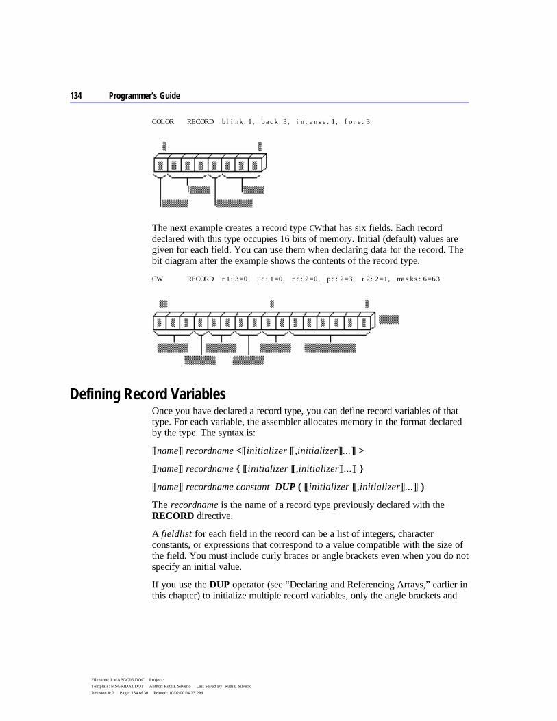
134 Programmer’s Guide
Filename: LMAPGC05.DOC Project: Template: MSGRIDA1.DOT Author: Ruth L Silverio Last Saved By: Ruth L Silverio Revision #: 2 Page: 134 of 30 Printed: 10/02/00 04:23 PM
COLOR RECORD blink:1, back:3, intense:1, fore:3
The next example creates a record type CW that has six fields. Each record declared with this type occupies 16 bits of memory. Initial (default) values are given for each field. You can use them when declaring data for the record. The bit diagram after the example shows the contents of the record type.
CW RECORD r1:3=0, ic:1=0, rc:2=0, pc:2=3, r2:2=1, masks:6=63
Defining Record Variables Once you have declared a record type, you can define record variables of that type. For each variable, the assembler allocates memory in the format declared by the type. The syntax is:
[[name]] recordname <[[initializer [[,initializer]]...]] >
[[name]] recordname { [[initializer [[,initializer]]...]] }
[[name]] recordname constant DUP ( [[initializer [[,initializer]]...]] )
The recordname is the name of a record type previously declared with the RECORD directive.
A fieldlist for each field in the record can be a list of integers, character constants, or expressions that correspond to a value compatible with the size of the field. You must include curly braces or angle brackets even when you do not specify an initial value.
If you use the DUP operator (see “Declaring and Referencing Arrays,” earlier in this chapter) to initialize multiple record variables, only the angle brackets and

Chapter 5 Defining and Using Complex Data Types 135
Filename: LMAPGC05.DOC Project: Template: MSGRIDA1.DOT Author: Ruth L Silverio Last Saved By: Ruth L Silverio Revision #: 2 Page: 135 of 31 Printed: 10/02/00 04:23 PM
any initial values need to be enclosed in parentheses. For example, you can define an array of record variables with
xmas COLOR 50 DUP ( <1, 2, 0, 4> )
You do not have to initialize all fields in a record. If an initial value is blank, the assembler automatically stores the default initial value of the field. If there is no default value, the assembler clears each bit in the field.
The definition in the following example creates a variable named warning whose type is given by the record type COLOR. The initial values of the fields in the variable are set to the values given in the record definition. The initial values override any default record values given in the declaration.
COLOR RECORD blink:1,back:3,intense:1,fore:3 ; Record ; declaration warning COLOR <1, 0, 1, 4> ; Record ; definition
LENGTHOF, SIZEOF, and TYPE with Records The SIZEOF and TYPE operators applied to a record name return the number of bytes used by the record. SIZEOF returns the number of bytes a record variable occupies. You cannot use LENGTHOF with a record declaration, but you can use it with defined record variables. LENGTHOF returns the number of records in an array of records, or 1 for a single record variable. The following example illustrates these points.
; Record definition ; 9 bits stored in 2 bytes RGBCOLOR RECORD red:3, green:3, blue:3 mov ax, RGBCOLOR ; Equivalent to "mov ax, 01FFh" ; mov ax, LENGTHOF RGBCOLOR ; Illegal since LENGTHOF can ; apply only to data label mov ax, SIZEOF RGBCOLOR ; Equivalent to "mov ax, 2" mov ax, TYPE RGBCOLOR ; Equivalent to "mov ax, 2"
136 Programmer’s Guide
Filename: LMAPGC05.DOC Project: Template: MSGRIDA1.DOT Author: Ruth L Silverio Last Saved By: Ruth L Silverio Revision #: 2 Page: 136 of 32 Printed: 10/02/00 04:23 PM
; Record instance ; 8 bits stored in 1 byte RGBCOLOR2 RECORD red:3, green:3, blue:2 rgb RGBCOLOR2 <1, 1, 1> ; Initialize to 00100101y mov ax, RGBCOLOR2 ; Equivalent to ; "mov ax, 00FFh" mov ax, LENGTHOF rgb ; Equivalent to "mov ax, 1" mov ax, SIZEOF rgb ; Equivalent to "mov ax, 1" mov ax, TYPE rgb ; Equivalent to "mov ax, 1"
Record Operators The WIDTH operator (used only with records) returns the width in bits of a record or record field. The MASK operator returns a bit mask for the bit positions occupied by the given record field. A bit in the mask contains a 1 if that bit corresponds to a bit field. The following example shows how to use MASK and WIDTH.
.DATA COLOR RECORD blink:1, back:3, intense:1, fore:3 message COLOR <1, 5, 1, 1> wblink EQU WIDTH blink ; "wblink" = 1 wback EQU WIDTH back ; "wback" = 3 wintens EQU WIDTH intense ; "wintens" = 1 wfore EQU WIDTH fore ; "wfore" = 3 wcolor EQU WIDTH COLOR ; "wcolor" = 8 .CODE . . . mov ah, message ; Load initial 1101 1001 and ah, NOT MASK back ; Turn off AND 1000 1111 ; "back" --------- ; 1000 1001 or ah, MASK blink ; Turn on OR 1000 0000 ; "blink" --------- ; 1000 1001 xor ah, MASK intense ; Toggle XOR 0000 1000 ; "intense" --------- ; 1000 0001 IF (WIDTH COLOR) GT 8 ; If color is 16 bit, load mov ax, message ; into 16-bit register ELSE ; else mov al, message ; load into low 8-bit register xor ah, ah ; and clear high 8-bits ENDIF

Chapter 5 Defining and Using Complex Data Types 137
Filename: LMAPGC05.DOC Project: Template: MSGRIDA1.DOT Author: Ruth L Silverio Last Saved By: Ruth L Silverio Revision #: 2 Page: 137 of 33 Printed: 10/02/00 04:23 PM
The example continues by illustrating several ways in which record fields can serve as operands and expressions:
; Rotate "back" of "message" without changing other values mov al, message ; Load value from memory mov ah, al ; Save a copy for work 1101 1001=ah/al and al, NOT MASK back; Mask out old bits AND 1000 1111=mask ; to save old message --------- ; 1000 1001=al mov cl, back ; Load bit position shr ah, cl ; Shift to right 0000 1101=ah inc ah ; Increment 0000 1110=ah shl ah, cl ; Shift left again 1110 0000=ah and ah, MASK back ; Mask off extra bits AND 0111 0000=mask ; to get new message --------- ; 0110 0000 ah or ah, al ; Combine old and new OR 1000 1001 al ; --------- mov message, ah ; Write back to memory 1110 1001 ah
Record variables are often used with the logical operators to perform logical operations on the bit fields of the record, as in the previous example using the MASK operator.

135
Filename: LMAPGC06.DOC Project: Template: MSGRIDA1.DOT Author: Terri Sharkey Last Saved By: Ruth L Silverio Revision #: 59 Page: 135 of 1 Printed: 10/02/00 04:23 PM
C H A P T E R 6
MASM requires different techniques for handling floating-point (real) numbers and binary coded decimal (BCD) numbers than for handling integers. You have two choices for working with real numbers — a math coprocessor or emulation routines.
Math coprocessors — the 8087, 80287, and 80387 chips — work with the main processor to handle real-number calculations. The 80486 processor performs floating-point operations directly. All information in this chapter pertaining to the 80387 coprocessor applies to the 80486DX processor as well. It does not apply to the 80486SX, which does not provide an on-chip coprocessor.
This chapter begins with a summary of the directives and formats of floating-point data that you need to allocate memory storage and initialize variables before you can work with floating-point numbers.
The chapter then explains how to use a math coprocessor for floating-point operations. It covers:
u The architecture of the registers. u The operands for the coprocessor instruction formats. u The coordination of coprocessor and main processor memory access. u The basic groups of coprocessor instructions — for loading and storing data,
doing arithmetic calculations, and controlling program flow.
The next main section describes emulation libraries. The emulation routines provided with all Microsoft high-level languages enable you to use coprocessor instructions as though your computer had a math coprocessor. However, some coprocessor instructions are not handled by emulation, as this section explains.
Finally, because math coprocessor and emulation routines can also operate on BCD numbers, this chapter includes the instruction set for these numbers.
Using Floating-Point and Binary Coded Decimal Numbers

136 Programmer’s Guide
Filename: LMAPGC06.DOC Project: Template: MSGRIDA1.DOT Author: Terri Sharkey Last Saved By: Ruth L Silverio Revision #: 59 Page: 136 of 2 Printed: 10/02/00 04:23 PM
Using Floating-Point Numbers Before using floating-point data in your program, you need to allocate the memory storage for the data. You can then initialize variables either as real numbers in decimal form or as encoded hexadecimals. The assembler stores allocated data in 10-byte IEEE format. This section covers floating-point declarations and floating-point data formats.
Declaring Floating-Point Variables and Constants You can allocate real constants using the REAL4, REAL8, and REAL10 directives. These directives allocate the following floating-point numbers:
Directive Size
REAL4 Short (32-bit) real numbers REAL8 Long (64-bit) real numbers REAL10 10-byte (80-bit) real numbers and BCD numbers
Table 6.1 lists the possible ranges for floating-point variables. The number of significant digits can vary in an arithmetic operation as the least-significant digit may be lost through rounding errors. This occurs regularly for short and long real numbers, so you should assume the lesser value of significant digits shown in Table 6.1. Ten-byte real numbers are much less susceptible to rounding errors for reasons described in the next section. However, under certain circumstances, 10-byte real operations can have a precision of only 18 digits.
Table 6.1 Ranges of Floating-Point Variables
Data Type
Bits
Significant Digits
Approximate Range
Short real 32 6–7 1.18 x 10-38 to 3.40 x 1038 Long real 64 15–16 2.23 x 10-308 to 1.79 x 10308 10-byte real 80 19 3.37 x 10-4932 to 1.18 x 104932
With versions of MASM prior to 6.0, the DD, DQ, and DT directives could allocate real constants. MASM 6.1 still supports these directives, but the variables are integers rather than floating-point values. Although this makes no difference in the assembly code, CodeView displays the values incorrectly.
You can specify floating-point constants either as decimal constants or as encoded hexadecimal constants. You can express decimal real-number constants in the form:
[[+ | –]] integer[[fraction]][[E[[+ | –]]exponent]]

Chapter 6 Using Floating-Point and Binary Coded Decimal Numbers 137
Filename: LMAPGC06.DOC Project: Template: MSGRIDA1.DOT Author: Terri Sharkey Last Saved By: Ruth L Silverio Revision #: 59 Page: 137 of 3 Printed: 10/02/00 04:23 PM
For example, the numbers 2.523E1 and -3.6E-2 are written in the correct decimal format. You can use these numbers as initializers for real-number variables.
The assembler always evaluates digits of real numbers as base 10. It converts real-number constants given in decimal format to a binary format. The sign, exponent, and decimal part of the real number are encoded as bit fields within the number.
You can also specify the encoded format directly with hexadecimal digits (0–9 plus A–F). The number must begin with a decimal digit (0–9) and end with the real-number designator (R). It cannot be signed. For example, the hexadecimal number 3F800000r can serve as an initializer for a doubleword-sized variable.
The maximum range of exponent values and the number of digits required in the hexadecimal number depend on the directive. The number of digits for encoded numbers used with REAL4, REAL8, and REAL10 must be 8, 16, and 20 digits, respectively. If the number has a leading zero, the number must be 9, 17, or 21 digits.
Examples of decimal constant and hexadecimal specifications are shown here:
; Real numbers short REAL4 25.23 ; IEEE format double REAL8 2.523E1 ; IEEE format tenbyte REAL10 2523.0E-2 ; 10-byte real format ; Encoded as hexadecimals ieeeshort REAL4 3F800000r ; 1.0 as IEEE short ieeedouble REAL8 3FF0000000000000r ; 1.0 as IEEE long temporary REAL10 3FFF8000000000000000r ; 1.0 as 10-byte ; real
The section “Storing Numbers in Floating-Point Format,” following, explains the IEEE formats — the way the assembler actually stores the data.
Pascal or C programmers may prefer to create language-specific TYPEDEF declarations, as illustrated in this example:

138 Programmer’s Guide
Filename: LMAPGC06.DOC Project: Template: MSGRIDA1.DOT Author: Terri Sharkey Last Saved By: Ruth L Silverio Revision #: 59 Page: 138 of 4 Printed: 10/02/00 04:23 PM
; C-language specific float TYPEDEF REAL4 double TYPEDEF REAL8 long_double TYPEDEF REAL10 ; Pascal-language specific SINGLE TYPEDEF REAL4 DOUBLE TYPEDEF REAL8 EXTENDED TYPEDEF REAL10
For applications of TYPEDEF, see “Defining Pointer Types with TYPEDEF,” page 75.
Storing Numbers in Floating-Point Format The assembler stores floating-point variables in the IEEE format. MASM 6.1 does not support .MSFLOAT and Microsoft binary format, which are available in version 5.1 and earlier. Figure 6.1 illustrates the IEEE format for encoding short (4-byte), long (8-byte), and 10-byte real numbers. Although this figure places the most significant bit first for illustration, low bytes actually appear first in memory.
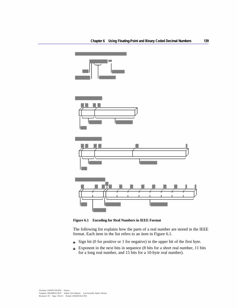
Chapter 6 Using Floating-Point and Binary Coded Decimal Numbers 139
Filename: LMAPGC06.DOC Project: Template: MSGRIDA1.DOT Author: Terri Sharkey Last Saved By: Ruth L Silverio Revision #: 59 Page: 139 of 5 Printed: 10/02/00 04:23 PM
Figure 6.1 Encoding for Real Numbers in IEEE Format
The following list explains how the parts of a real number are stored in the IEEE format. Each item in the list refers to an item in Figure 6.1.
u Sign bit (0 for positive or 1 for negative) in the upper bit of the first byte. u Exponent in the next bits in sequence (8 bits for a short real number, 11 bits
for a long real number, and 15 bits for a 10-byte real number).
140 Programmer’s Guide
Filename: LMAPGC06.DOC Project: Template: MSGRIDA1.DOT Author: Terri Sharkey Last Saved By: Ruth L Silverio Revision #: 59 Page: 140 of 6 Printed: 10/02/00 04:23 PM
u The integer part of the significand in bit 63 for the 10-byte real format. By absorbing carry values, this bit allows 10-byte real operations to preserve precision to 19 digits. The integer part is always 1 in short and long real numbers; consequently, these formats do not provide a bit for the integer, since there is no point in storing it.
u Decimal part of the significand in the remaining bits. The length is 23 bits for short real numbers, 52 bits for long real numbers, and 63 bits for 10-byte real numbers.
The exponent field represents a multiplier 2n. To accommodate negative exponents (such as 2-6), the value in the exponent field is biased; that is, the actual exponent is determined by subtracting the appropriate bias value from the value in the exponent field. For example, the bias for short real numbers is 127. If the value in the exponent field is 130, the exponent represents a value of 2130-127, or 23. The bias for long real numbers is 1,023. The bias for 10-byte real numbers is 16,383.
Once you have declared floating-point data for your program, you can use coprocessor or emulator instructions to access the data. The next section focuses on the coprocessor architecture, instructions, and operands required for floating-point operations.
Using a Math Coprocessor When used with real numbers, packed BCD numbers, or long integers, coprocessors (the 8087, 80287, 80387, and 80486) calculate many times faster than the 8086-based processors. The coprocessor handles data with its own registers. The organization of these registers can be one of the four formats for using operands explained in “Instruction and Operand Formats,” later in this section.
This section describes how the coprocessor transfers data to and from the coprocessor, coordinates processor and coprocessor operations, and controls program flow.
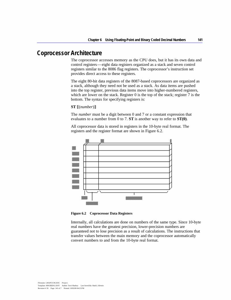
Chapter 6 Using Floating-Point and Binary Coded Decimal Numbers 141
Filename: LMAPGC06.DOC Project: Template: MSGRIDA1.DOT Author: Terri Sharkey Last Saved By: Ruth L Silverio Revision #: 59 Page: 141 of 7 Printed: 10/02/00 04:23 PM
Coprocessor Architecture The coprocessor accesses memory as the CPU does, but it has its own data and control registers — eight data registers organized as a stack and seven control registers similar to the 8086 flag registers. The coprocessor’s instruction set provides direct access to these registers.
The eight 80-bit data registers of the 8087-based coprocessors are organized as a stack, although they need not be used as a stack. As data items are pushed into the top register, previous data items move into higher-numbered registers, which are lower on the stack. Register 0 is the top of the stack; register 7 is the bottom. The syntax for specifying registers is:
ST [[(number)]]
The number must be a digit between 0 and 7 or a constant expression that evaluates to a number from 0 to 7. ST is another way to refer to ST(0).
All coprocessor data is stored in registers in the 10-byte real format. The registers and the register format are shown in Figure 6.2.
Figure 6.2 Coprocessor Data Registers
Internally, all calculations are done on numbers of the same type. Since 10-byte real numbers have the greatest precision, lower-precision numbers are guaranteed not to lose precision as a result of calculations. The instructions that transfer values between the main memory and the coprocessor automatically convert numbers to and from the 10-byte real format.
142 Programmer’s Guide
Filename: LMAPGC06.DOC Project: Template: MSGRIDA1.DOT Author: Terri Sharkey Last Saved By: Ruth L Silverio Revision #: 59 Page: 142 of 8 Printed: 10/02/00 04:23 PM
Instruction and Operand Formats Because of the stack organization of registers, you can consider registers either as elements on a stack or as registers much like 8086-family registers. Table 6.2 lists the four main groups of coprocessor instructions and the general syntax for each. The names given to the instruction format reflect the way the instruction uses the coprocessor registers. The instruction operands are placed in the coprocessor data registers before the instruction executes.
Table 6.2 Coprocessor Operand Formats
Instruction Format
Syntax
Implied Operands
Example
Classical stack Finstruction ST, ST(1) fadd
Memory Finstruction memory ST fadd memloc
Register Finstruction ST(num), ST Finstruction ST, ST(num)
—
fadd st(5), st fadd st, st(3)
Register pop FinstructionP ST(num), ST — faddp st(4), st
You can easily recognize coprocessor instructions because, unlike all 8086-family instruction mnemonics, they start with the letter F. Coprocessor instructions can never have immediate operands and, with the exception of the FSTSW instruction, they cannot have processor registers as operands.
Classical-Stack Format Instructions in the classical-stack format treat the coprocessor registers like items on a stack — thus its name. Items are pushed onto or popped off the top elements of the stack. Since only the top item can be accessed on a traditional stack, there is no need to specify operands. The first (top) register (and the second, if the instruction needs two operands) is always assumed.
ST (the top of the stack) is the source operand in coprocessor arithmetic operations. ST(1), the second register, is the destination. The result of the operation replaces the destination operand, and the source is popped off the stack. This leaves the result at the top of the stack.
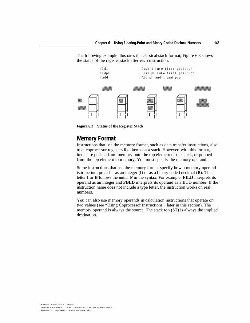
Chapter 6 Using Floating-Point and Binary Coded Decimal Numbers 143
Filename: LMAPGC06.DOC Project: Template: MSGRIDA1.DOT Author: Terri Sharkey Last Saved By: Ruth L Silverio Revision #: 59 Page: 143 of 9 Printed: 10/02/00 04:23 PM
The following example illustrates the classical-stack format; Figure 6.3 shows the status of the register stack after each instruction.
fld1 ; Push 1 into first position fldpi ; Push pi into first position fadd ; Add pi and 1 and pop
Figure 6.3 Status of the Register Stack
Memory Format Instructions that use the memory format, such as data transfer instructions, also treat coprocessor registers like items on a stack. However, with this format, items are pushed from memory onto the top element of the stack, or popped from the top element to memory. You must specify the memory operand.
Some instructions that use the memory format specify how a memory operand is to be interpreted — as an integer (I) or as a binary coded decimal (B). The letter I or B follows the initial F in the syntax. For example, FILD interprets its operand as an integer and FBLD interprets its operand as a BCD number. If the instruction name does not include a type letter, the instruction works on real numbers.
You can also use memory operands in calculation instructions that operate on two values (see “Using Coprocessor Instructions,” later in this section). The memory operand is always the source. The stack top (ST) is always the implied destination.
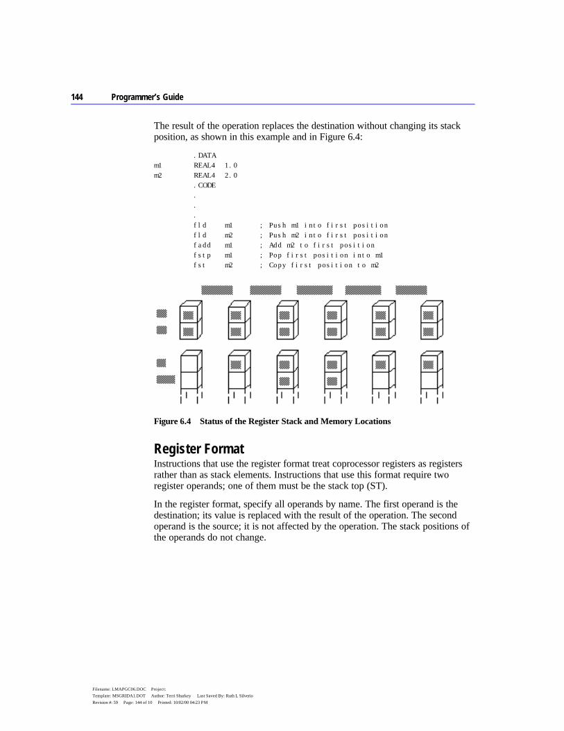
144 Programmer’s Guide
Filename: LMAPGC06.DOC Project: Template: MSGRIDA1.DOT Author: Terri Sharkey Last Saved By: Ruth L Silverio Revision #: 59 Page: 144 of 10 Printed: 10/02/00 04:23 PM
The result of the operation replaces the destination without changing its stack position, as shown in this example and in Figure 6.4:
.DATA m1 REAL4 1.0 m2 REAL4 2.0 .CODE . . . fld m1 ; Push m1 into first position fld m2 ; Push m2 into first position fadd m1 ; Add m2 to first position fstp m1 ; Pop first position into m1 fst m2 ; Copy first position to m2
Figure 6.4 Status of the Register Stack and Memory Locations
Register Format Instructions that use the register format treat coprocessor registers as registers rather than as stack elements. Instructions that use this format require two register operands; one of them must be the stack top (ST).
In the register format, specify all operands by name. The first operand is the destination; its value is replaced with the result of the operation. The second operand is the source; it is not affected by the operation. The stack positions of the operands do not change.
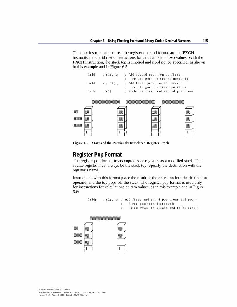
Chapter 6 Using Floating-Point and Binary Coded Decimal Numbers 145
Filename: LMAPGC06.DOC Project: Template: MSGRIDA1.DOT Author: Terri Sharkey Last Saved By: Ruth L Silverio Revision #: 59 Page: 145 of 11 Printed: 10/02/00 04:23 PM
The only instructions that use the register operand format are the FXCH instruction and arithmetic instructions for calculations on two values. With the FXCH instruction, the stack top is implied and need not be specified, as shown in this example and in Figure 6.5:
fadd st(1), st ; Add second position to first - ; result goes in second position fadd st, st(2) ; Add first position to third - ; result goes in first position fxch st(1) ; Exchange first and second positions
Figure 6.5 Status of the Previously Initialized Register Stack
Register-Pop Format The register-pop format treats coprocessor registers as a modified stack. The source register must always be the stack top. Specify the destination with the register’s name.
Instructions with this format place the result of the operation into the destination operand, and the top pops off the stack. The register-pop format is used only for instructions for calculations on two values, as in this example and in Figure 6.6:
faddp st(2), st ; Add first and third positions and pop - ; first position destroyed; ; third moves to second and holds result

146 Programmer’s Guide
Filename: LMAPGC06.DOC Project: Template: MSGRIDA1.DOT Author: Terri Sharkey Last Saved By: Ruth L Silverio Revision #: 59 Page: 146 of 12 Printed: 10/02/00 04:23 PM
Figure 6.6 Status of the Already Initialized Register Stack
Coordinating Memory Access The math coprocessor and main processor work simultaneously. However, since the coprocessor cannot handle device input or output, data originates in the main processor.
The main processor and the coprocessor have their own registers, which are separate and inaccessible to each other. They exchange data through memory, since memory is available to both.
When using the coprocessor, follow these three steps:
1. Load data from memory to coprocessor registers. 2. Process the data. 3. Store the data from coprocessor registers back to memory.
Step 2, processing the data, can occur while the main processor is handling other tasks. Steps 1 and 3 must be coordinated with the main processor so that the processor and coprocessor do not try to access the same memory at the same time; otherwise, problems of coordinating memory access can occur. Since the processor and coprocessor work independently, they may not finish working on memory in the order in which you give instructions. The two potential timing conflicts that can occur are handled in different ways.
One timing conflict results from a coprocessor instruction following a processor instruction. The processor may have to wait until the coprocessor finishes if the next processor instruction requires the result of the coprocessor’s calculation. You do not have to write your code to avoid this conflict, however. The assembler coordinates this timing automatically for the 8088 and 8086 processors, and the processor coordinates it automatically on the 80186–80486 processors. This is the case shown in the first example that follows.
Another conflict results from a processor instruction that accesses memory following a coprocessor instruction that accesses the same memory. The processor can try to load a variable that is still being used by the coprocessor. You need careful synchronization to control the timing, and this synchronization is not automatic on the 8087 coprocessor. For code to run correctly on the 8087, you must include WAIT or FWAIT (mnemonics for the same instruction) to ensure that the coprocessor finishes before the processor begins, as shown in the second example.

Chapter 6 Using Floating-Point and Binary Coded Decimal Numbers 147
Filename: LMAPGC06.DOC Project: Template: MSGRIDA1.DOT Author: Terri Sharkey Last Saved By: Ruth L Silverio Revision #: 59 Page: 147 of 13 Printed: 10/02/00 04:23 PM
In this situation, the processor does not generate the FWAIT instruction automatically.
; Processor instruction first - No wait needed mov WORD PTR mem32[0], ax ; Load memory mov WORD PTR mem32[2], dx fild mem32 ; Load to register ; Coprocessor instruction first - Wait needed (for 8087) fist mem32 ; Store to memory fwait ; Wait until coprocessor ; is done mov ax, WORD PTR mem32[0] ; Move to register mov dx, WORD PTR mem32[2]
When generating code for the 8087 coprocessor, the assembler automatically inserts a WAIT instruction before the coprocessor instruction. However, if you use the .286 or .386 directive, the compiler assumes that the coprocessor instructions are for the 80287 or 80387 and does not insert the WAIT instruction. If your code does not need to run on an 8086 or 8088 processor, you can make your programs smaller and more efficient by using the .286 or .386 directive.
Using Coprocessor Instructions The 8087 family of coprocessors has separate instructions for each of the following operations:
u Loading and storing data u Doing arithmetic calculations u Controlling program flow
The following sections explain the available instructions and show how to use them for each of these operations. For general syntax information, see “Instruction and Operand Formats,” earlier in this section.
Loading and Storing Data Data-transfer instructions copy data between main memory and the coprocessor registers or between different coprocessor registers. Two principles govern data transfers:
u The choice of instruction determines whether a value in memory is considered an integer, a BCD number, or a real number. The value is always considered a 10-byte real number once transferred to the coprocessor.
148 Programmer’s Guide
Filename: LMAPGC06.DOC Project: Template: MSGRIDA1.DOT Author: Terri Sharkey Last Saved By: Ruth L Silverio Revision #: 59 Page: 148 of 14 Printed: 10/02/00 04:23 PM
u The size of the operand determines the size of a value in memory. Values in the coprocessor always take up 10 bytes.
You can transfer data to stack registers using load commands. These commands push data onto the stack from memory or from coprocessor registers. Store commands remove data. Some store commands pop data off the register stack into memory or coprocessor registers; others simply copy the data without changing it on the stack.
If you use constants as operands, you cannot load them directly into coprocessor registers. You must allocate memory and initialize a variable to a constant value. That variable can then be loaded by using one of the load instructions in the following list.
The math coprocessor offers a few special instructions for loading certain constants. You can load 0, 1, pi, and several common logarithmic values directly. Using these instructions is faster and often more precise than loading the values from initialized variables.
All instructions that load constants have the stack top as the implied destination operand. The constant to be loaded is the implied source operand.
The coprocessor data area, or parts of it, can also be moved to memory and later loaded back. You may want to do this to save the current state of the coprocessor before executing a procedure. After the procedure ends, restore the previous status. Saving coprocessor data is also useful when you want to modify coprocessor behavior by writing certain data to main memory, operating on the data with 8086-family instructions, and then loading it back to the coprocessor data area.
Use the following instructions for transferring numbers to and from registers:
Instruction(s) Description
FLD, FST, FSTP Loads and stores real numbers FILD, FIST, FISTP Loads and stores binary integers FBLD Loads BCD FBSTP Stores BCD FXCH Exchanges register values FLDZ Pushes 0 into ST FLD1 Pushes 1 into ST FLDPI Pushes the value of pi into ST FLDCW mem2byte Loads the control word into the coprocessor F[[N]]STCW mem2byte Stores the control word in memory

Chapter 6 Using Floating-Point and Binary Coded Decimal Numbers 149
Filename: LMAPGC06.DOC Project: Template: MSGRIDA1.DOT Author: Terri Sharkey Last Saved By: Ruth L Silverio Revision #: 59 Page: 149 of 15 Printed: 10/02/00 04:23 PM
FLDENV mem14byte Loads environment from memory F[[N]]STENV mem14byte Stores environment in memory Instruction(s) Description
FRSTOR mem94byte Restores state from memory F[[N]]SAVE mem94byte Saves state in memory FLDL2E Pushes the value of log2e into ST FLDL2T Pushes log210 into ST FLDLG2 Pushes log102 into ST FLDLN2 Pushes loge2 into ST
The following example and Figure 6.7 illustrate some of these instructions:
.DATA m1 REAL4 1.0 m2 REAL4 2.0 .CODE fld m1 ; Push m1 into first item fld st(2) ; Push third item into first fst m2 ; Copy first item to m2 fxch st(2) ; Exchange first and third items fstp m1 ; Pop first item into m1
Figure 6.7 Status of the Register Stack: Main Memory and Coprocessor
150 Programmer’s Guide
Filename: LMAPGC06.DOC Project: Template: MSGRIDA1.DOT Author: Terri Sharkey Last Saved By: Ruth L Silverio Revision #: 59 Page: 150 of 16 Printed: 10/02/00 04:23 PM
Doing Arithmetic Calculations Most of the coprocessor instructions for arithmetic operations have several forms, depending on the operand used. You do not need to specify the operand type in the
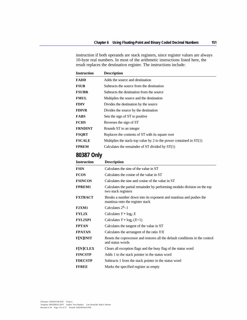
Chapter 6 Using Floating-Point and Binary Coded Decimal Numbers 151
Filename: LMAPGC06.DOC Project: Template: MSGRIDA1.DOT Author: Terri Sharkey Last Saved By: Ruth L Silverio Revision #: 59 Page: 151 of 17 Printed: 10/02/00 04:23 PM
instruction if both operands are stack registers, since register values are always 10-byte real numbers. In most of the arithmetic instructions listed here, the result replaces the destination register. The instructions include:
Instruction Description
FADD Adds the source and destination FSUB Subtracts the source from the destination FSUBR Subtracts the destination from the source FMUL Multiplies the source and the destination FDIV Divides the destination by the source FDIVR Divides the source by the destination FABS Sets the sign of ST to positive FCHS Reverses the sign of ST FRNDINT Rounds ST to an integer FSQRT Replaces the contents of ST with its square root FSCALE Multiplies the stack-top value by 2 to the power contained in ST(1) FPREM Calculates the remainder of ST divided by ST(1)
80387 Only Instruction Description
FSIN Calculates the sine of the value in ST FCOS Calculates the cosine of the value in ST FSINCOS Calculates the sine and cosine of the value in ST FPREM1 Calculates the partial remainder by performing modulo division on the top
two stack registers FXTRACT Breaks a number down into its exponent and mantissa and pushes the
mantissa onto the register stack F2XM1 Calculates 2x–1 FYL2X Calculates Y * log2 X FYL2XP1 Calculates Y * log2 (X+1) FPTAN Calculates the tangent of the value in ST FPATAN Calculates the arctangent of the ratio Y/X F[[N]]INIT Resets the coprocessor and restores all the default conditions in the control
and status words F[[N]]CLEX Clears all exception flags and the busy flag of the status word FINCSTP Adds 1 to the stack pointer in the status word FDECSTP Subtracts 1 from the stack pointer in the status word FFREE Marks the specified register as empty
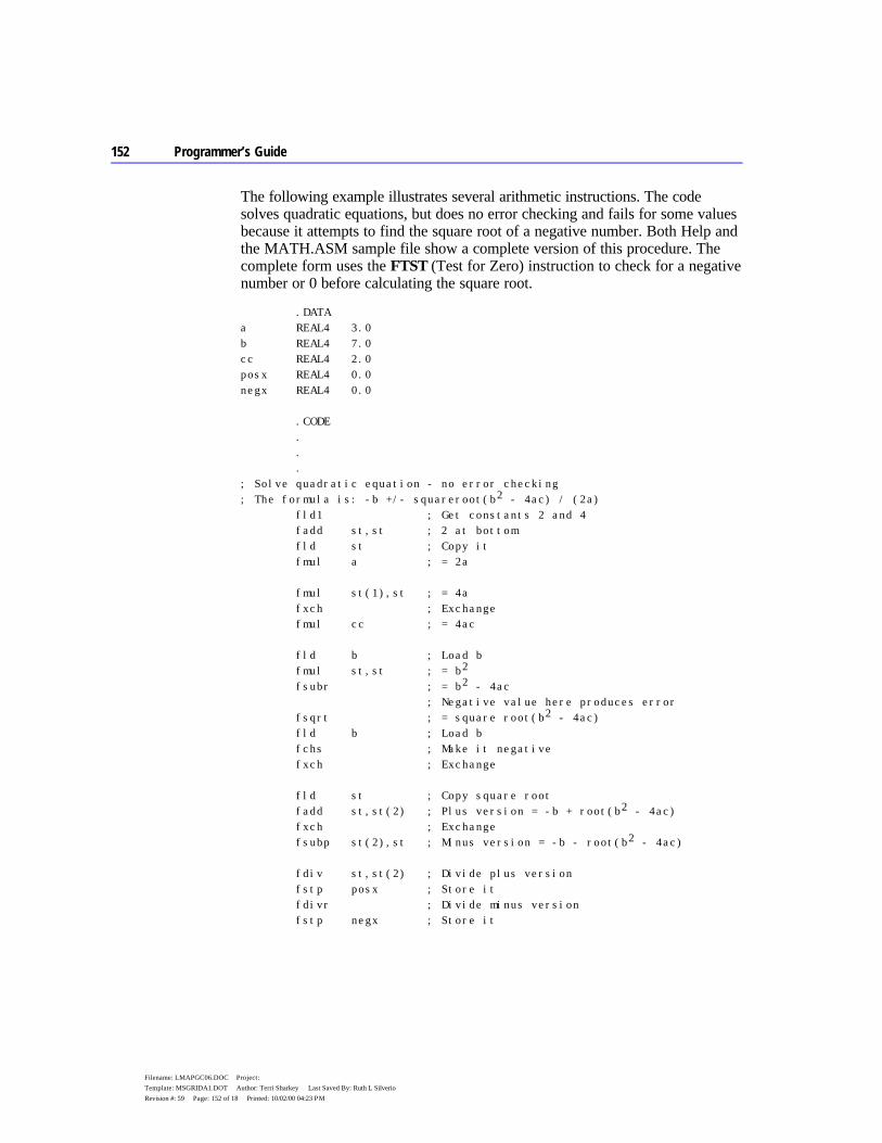
152 Programmer’s Guide
Filename: LMAPGC06.DOC Project: Template: MSGRIDA1.DOT Author: Terri Sharkey Last Saved By: Ruth L Silverio Revision #: 59 Page: 152 of 18 Printed: 10/02/00 04:23 PM
The following example illustrates several arithmetic instructions. The code solves quadratic equations, but does no error checking and fails for some values because it attempts to find the square root of a negative number. Both Help and the MATH.ASM sample file show a complete version of this procedure. The complete form uses the FTST (Test for Zero) instruction to check for a negative number or 0 before calculating the square root.
.DATA a REAL4 3.0 b REAL4 7.0 cc REAL4 2.0 posx REAL4 0.0 negx REAL4 0.0 .CODE . . . ; Solve quadratic equation - no error checking ; The formula is: -b +/- squareroot(b2 - 4ac) / (2a) fld1 ; Get constants 2 and 4 fadd st,st ; 2 at bottom fld st ; Copy it fmul a ; = 2a fmul st(1),st ; = 4a fxch ; Exchange fmul cc ; = 4ac fld b ; Load b fmul st,st ; = b2 fsubr ; = b2 - 4ac ; Negative value here produces error fsqrt ; = square root(b2 - 4ac) fld b ; Load b fchs ; Make it negative fxch ; Exchange fld st ; Copy square root fadd st,st(2) ; Plus version = -b + root(b2 - 4ac) fxch ; Exchange fsubp st(2),st ; Minus version = -b - root(b2 - 4ac) fdiv st,st(2) ; Divide plus version fstp posx ; Store it fdivr ; Divide minus version fstp negx ; Store it
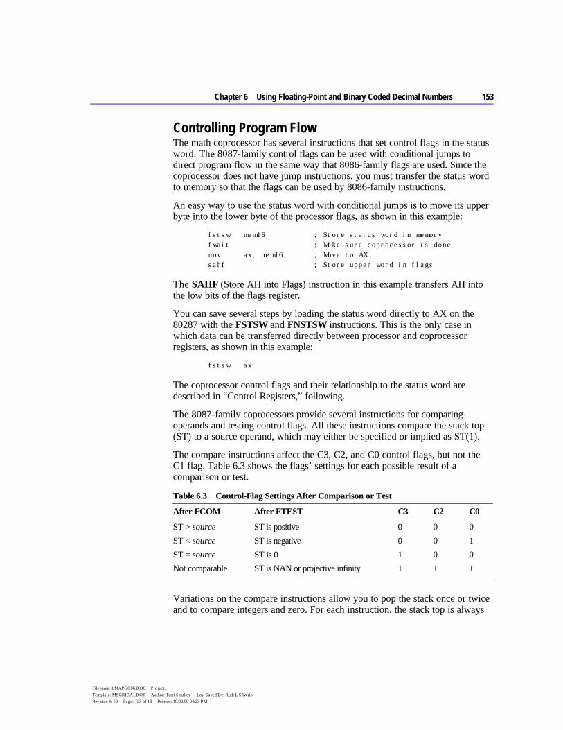
Chapter 6 Using Floating-Point and Binary Coded Decimal Numbers 153
Filename: LMAPGC06.DOC Project: Template: MSGRIDA1.DOT Author: Terri Sharkey Last Saved By: Ruth L Silverio Revision #: 59 Page: 153 of 19 Printed: 10/02/00 04:23 PM
Controlling Program Flow The math coprocessor has several instructions that set control flags in the status word. The 8087-family control flags can be used with conditional jumps to direct program flow in the same way that 8086-family flags are used. Since the coprocessor does not have jump instructions, you must transfer the status word to memory so that the flags can be used by 8086-family instructions.
An easy way to use the status word with conditional jumps is to move its upper byte into the lower byte of the processor flags, as shown in this example:
fstsw mem16 ; Store status word in memory fwait ; Make sure coprocessor is done mov ax, mem16 ; Move to AX sahf ; Store upper word in flags
The SAHF (Store AH into Flags) instruction in this example transfers AH into the low bits of the flags register.
You can save several steps by loading the status word directly to AX on the 80287 with the FSTSW and FNSTSW instructions. This is the only case in which data can be transferred directly between processor and coprocessor registers, as shown in this example:
fstsw ax
The coprocessor control flags and their relationship to the status word are described in “Control Registers,” following.
The 8087-family coprocessors provide several instructions for comparing operands and testing control flags. All these instructions compare the stack top (ST) to a source operand, which may either be specified or implied as ST(1).
The compare instructions affect the C3, C2, and C0 control flags, but not the C1 flag. Table 6.3 shows the flags’ settings for each possible result of a comparison or test.
Table 6.3 Control-Flag Settings After Comparison or Test
After FCOM After FTEST C3 C2 C0
ST > source ST is positive 0 0 0 ST < source ST is negative 0 0 1 ST = source ST is 0 1 0 0 Not comparable ST is NAN or projective infinity 1 1 1
Variations on the compare instructions allow you to pop the stack once or twice and to compare integers and zero. For each instruction, the stack top is always
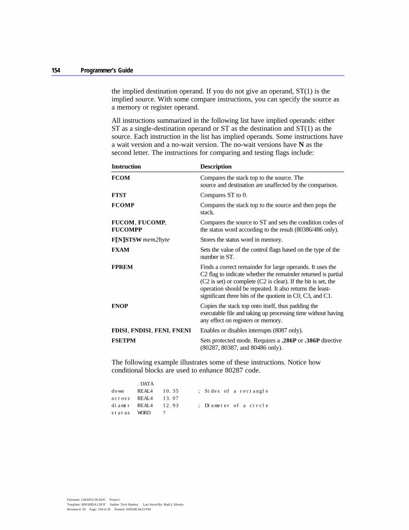
154 Programmer’s Guide
Filename: LMAPGC06.DOC Project: Template: MSGRIDA1.DOT Author: Terri Sharkey Last Saved By: Ruth L Silverio Revision #: 59 Page: 154 of 20 Printed: 10/02/00 04:23 PM
the implied destination operand. If you do not give an operand, ST(1) is the implied source. With some compare instructions, you can specify the source as a memory or register operand.
All instructions summarized in the following list have implied operands: either ST as a single-destination operand or ST as the destination and ST(1) as the source. Each instruction in the list has implied operands. Some instructions have a wait version and a no-wait version. The no-wait versions have N as the second letter. The instructions for comparing and testing flags include:
Instruction Description
FCOM Compares the stack top to the source. The source and destination are unaffected by the comparison.
FTST Compares ST to 0. FCOMP Compares the stack top to the source and then pops the
stack. FUCOM, FUCOMP, FUCOMPP
Compares the source to ST and sets the condition codes of the status word according to the result (80386/486 only).
F[[N]]STSW mem2byte Stores the status word in memory. FXAM Sets the value of the control flags based on the type of the
number in ST. FPREM Finds a correct remainder for large operands. It uses the
C2 flag to indicate whether the remainder returned is partial (C2 is set) or complete (C2 is clear). If the bit is set, the operation should be repeated. It also returns the least-significant three bits of the quotient in C0, C3, and C1.
FNOP Copies the stack top onto itself, thus padding the executable file and taking up processing time without having any effect on registers or memory.
FDISI, FNDISI, FENI, FNENI Enables or disables interrupts (8087 only). FSETPM Sets protected mode. Requires a .286P or .386P directive
(80287, 80387, and 80486 only).
The following example illustrates some of these instructions. Notice how conditional blocks are used to enhance 80287 code.
.DATA down REAL4 10.35 ; Sides of a rectangle across REAL4 13.07 diamtr REAL4 12.93 ; Diameter of a circle status WORD ?
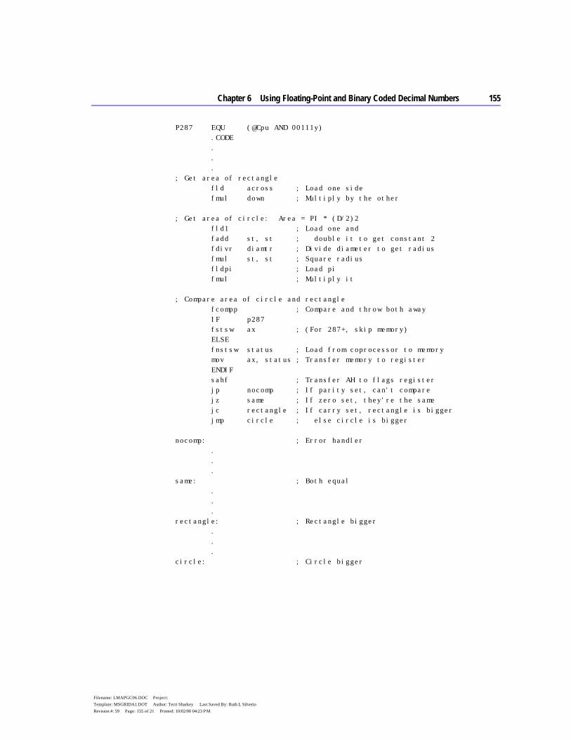
Chapter 6 Using Floating-Point and Binary Coded Decimal Numbers 155
Filename: LMAPGC06.DOC Project: Template: MSGRIDA1.DOT Author: Terri Sharkey Last Saved By: Ruth L Silverio Revision #: 59 Page: 155 of 21 Printed: 10/02/00 04:23 PM
P287 EQU (@Cpu AND 00111y) .CODE . . . ; Get area of rectangle fld across ; Load one side fmul down ; Multiply by the other ; Get area of circle: Area = PI * (D/2)2 fld1 ; Load one and fadd st, st ; double it to get constant 2 fdivr diamtr ; Divide diameter to get radius fmul st, st ; Square radius fldpi ; Load pi fmul ; Multiply it ; Compare area of circle and rectangle fcompp ; Compare and throw both away IF p287 fstsw ax ; (For 287+, skip memory) ELSE fnstsw status ; Load from coprocessor to memory mov ax, status ; Transfer memory to register ENDIF sahf ; Transfer AH to flags register jp nocomp ; If parity set, can't compare jz same ; If zero set, they're the same jc rectangle ; If carry set, rectangle is bigger jmp circle ; else circle is bigger nocomp: ; Error handler . . . same: ; Both equal . . . rectangle: ; Rectangle bigger . . . circle: ; Circle bigger

156 Programmer’s Guide
Filename: LMAPGC06.DOC Project: Template: MSGRIDA1.DOT Author: Terri Sharkey Last Saved By: Ruth L Silverio Revision #: 59 Page: 156 of 22 Printed: 10/02/00 04:23 PM
Additional instructions for the 80387/486 are FLDENVD and FLDENVW for loading the environment; FNSTENVD, FNSTENVW, FSTENVD, and FSTENVW for storing the environment state; FNSAVED, FNSAVEW, FSAVED, and FSAVEW for saving the coprocessor state; and FRSTORD and FRSTORW for restoring the coprocessor state.
The size of the code segment, not the operand size, determines the number of bytes loaded or stored with these instructions. The instructions ending with W store the 16-bit form of the control register data, and the instructions ending with D store the 32-bit form. For example, in 16-bit mode FSAVEW saves the 16-bit control register data. If you need to store the 32-bit form of the control register data, use FSAVED.
Control Registers Some of the flags of the seven 16-bit control registers control coprocessor operations, while others maintain the current status of the coprocessor. In this sense, they are much like the 8086-family flags registers (see Figure 6.8).
Figure 6.8 Coprocessor Control Registers
The status word register is the only commonly used control register. (The others are used mostly by systems programmers.) The format of the status word register is shown in Figure 6.9, which shows how the coprocessor control flags align with the processor flags. C3 overwrites the zero flag, C2 overwrites the parity flag, and C0 overwrites the carry flag. C1 overwrites an undefined bit, so it cannot be used directly with conditional jumps, although you can use the TEST instruction to
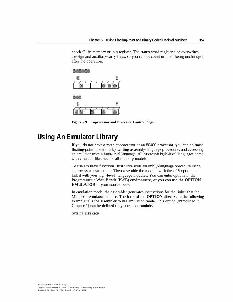
Chapter 6 Using Floating-Point and Binary Coded Decimal Numbers 157
Filename: LMAPGC06.DOC Project: Template: MSGRIDA1.DOT Author: Terri Sharkey Last Saved By: Ruth L Silverio Revision #: 59 Page: 157 of 23 Printed: 10/02/00 04:23 PM
check C1 in memory or in a register. The status word register also overwrites the sign and auxiliary-carry flags, so you cannot count on their being unchanged after the operation.
Figure 6.9 Coprocessor and Processor Control Flags
Using An Emulator Library If you do not have a math coprocessor or an 80486 processor, you can do most floating-point operations by writing assembly-language procedures and accessing an emulator from a high-level language. All Microsoft high-level languages come with emulator libraries for all memory models.
To use emulator functions, first write your assembly-language procedure using coprocessor instructions. Then assemble the module with the /FPi option and link it with your high-level – language modules. You can enter options in the Programmer’s WorkBench (PWB) environment, or you can use the OPTION EMULATOR in your source code.
In emulation mode, the assembler generates instructions for the linker that the Microsoft emulator can use. The form of the OPTION directive in the following example tells the assembler to use emulation mode. This option (introduced in Chapter 1) can be defined only once in a module.
OPTION EMULATOR

158 Programmer’s Guide
Filename: LMAPGC06.DOC Project: Template: MSGRIDA1.DOT Author: Terri Sharkey Last Saved By: Ruth L Silverio Revision #: 59 Page: 158 of 24 Printed: 10/02/00 04:23 PM
You can use emulator functions in a stand-alone assembler program by assembling with the /Cx command-line option and linking with the appropriate emulator library. The following fragment outlines a small-model program that contains floating-point instructions served by an emulator:
.MODEL small, c OPTION EMULATOR . . . PUBLIC main .CODE main: ; Program entry point must .STARTUP ; have name 'main' . fadd st, st ; Floating-point instructions fldpi ; emulated
Emulator libraries do not allow for all of the coprocessor instructions. The following floating-point instructions are not emulated:
FBLD FBSTP FCOS FDECSTP FINCSTP FINIT
FLDENV FNOP FPREM1 FRSTOR FRSTORW FRSTORD
FSAVE FSAVEW FSAVED FSETPM FSIN FSINCOS
FSTENV FUCOM FUCOMP FUCOMPP FXTRACT
For information about writing assembly-language procedures for high-level languages, see Chapter 12, “Mixed-Language Programming.”
Using Binary Coded Decimal Numbers Binary coded decimal (BCD) numbers allow calculations on large numbers without rounding errors. This characteristic makes BCD numbers a common choice for monetary calculations. Although BCDs can represent integers of any precision, the 8087-based coprocessors accommodate BCD numbers only in the range ±999,999,999,999,999,999.
This section explains how to define BCD numbers, how to access them with a math coprocessor or emulator, and how to perform simple BCD calculations on the main processor.
Defining BCD Constants and Variables Unpacked BCD numbers are made up of bytes containing a single decimal digit in the lower 4 bits of each byte. Packed BCD numbers are made up of bytes
Chapter 6 Using Floating-Point and Binary Coded Decimal Numbers 159
Filename: LMAPGC06.DOC Project: Template: MSGRIDA1.DOT Author: Terri Sharkey Last Saved By: Ruth L Silverio Revision #: 59 Page: 159 of 25 Printed: 10/02/00 04:23 PM
containing two decimal digits: one in the upper 4 bits and one in the lower 4 bits. The leftmost digit holds the sign (0 for positive, 1 for negative).
Packed BCD numbers are encoded in the 8087 coprocessor’s packed BCD format. They can be up to 18 digits long, packed two digits per byte. The assembler zero-pads BCDs initialized with fewer than 18 digits. Digit 20 is the sign bit, and digit 19 is reserved.
When you define an integer constant with the TBYTE directive and the current radix is decimal (t), the assembler interprets the number as a packed BCD number.
The syntax for specifying packed BCDs is the same as for other integers.
pos1 TBYTE 1234567890 ; Encoded as 00000000001234567890h neg1 TBYTE -1234567890 ; Encoded as 80000000001234567890h
Unpacked BCD numbers are stored one digit to a byte, with the value in the lower 4 bits. They can be defined using the BYTE directive. For example, an unpacked BCD number could be defined and initialized as follows:
unpackedr BYTE 1,5,8,2,5,2,9 ; Initialized to 9,252,851 unpackedf BYTE 9,2,5,2,8,5,1 ; Initialized to 9,252,851
As these two lines show, you can arrange digits backward or forward, depending on how you write the calculation routines that handle the numbers.
BCD Calculations on a Coprocessor As the previous section explains, BCDs differ from other numbers only in the way a program stores them in memory. Internally, a math coprocessor does not distinguish BCD integers from any other type. The coprocessor can load, calculate, and store packed BCD integers up to 18 digits long.
The coprocessor instruction
fbld bcd1
pushes the packed BCD number at bcd1 onto the coprocessor stack. When your code completes calculations on the number, place the result back into memory in BCD format with the instruction
fbstp bcd1
which discards the variable from the stack top.
160 Programmer’s Guide
Filename: LMAPGC06.DOC Project: Template: MSGRIDA1.DOT Author: Terri Sharkey Last Saved By: Ruth L Silverio Revision #: 59 Page: 160 of 26 Printed: 10/02/00 04:23 PM
BCD Calculations on the Main Processor The 8086-family of processors can perform simple arithmetic operations on BCD integers, but only one digit at a time. The main processor, like the coprocessor, operates internally on the number’s binary value. It requires additional code to translate the binary result back into BCD format.
The main processor provides instructions specifically designed to translate to and from BCD format. These instructions are called “ASCII-adjust” and “decimal-adjust” instructions. They get their names from Intel mnemonics that use the term “ASCII” to refer to unpacked BCD numbers and “decimal” to refer to packed BCD numbers.
Unpacked BCD Numbers When a calculation using two one-digit values produces a two-digit result, the instructions AAA, AAS, AAM, and AAD place the first digit in AL and the second in AH. If the digit in AL needs to carry to or borrow from the digit in AH, the instructions set the carry and auxiliary carry flags. The four ASCII-adjust instructions for unpacked BCDs are:
Instruction Description
AAA Adjusts after an addition operation. AAS Adjusts after a subtraction operation. AAM Adjusts after a multiplication operation. Always use with MUL, not with
IMUL. AAD Adjusts before a division operation. Unlike other BCD instructions, AAD
converts a BCD value to a binary value before the operation. After the operation, use AAM to adjust the quotient. The remainder is lost. If you need the remainder, save it in another register before adjusting the quotient. Then move it back to AL and adjust if necessary.
For processor arithmetic on unpacked BCD numbers, you must do the 8-bit arithmetic calculations on each digit separately, and assign the result to the AL register. After each operation, use the corresponding BCD instruction to adjust the result. The ASCII-adjust instructions do not take an operand and always work on the value in the AL register.
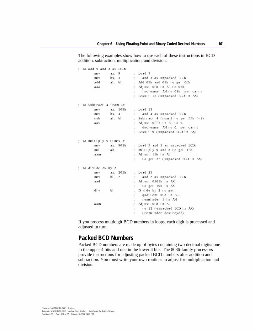
Chapter 6 Using Floating-Point and Binary Coded Decimal Numbers 161
Filename: LMAPGC06.DOC Project: Template: MSGRIDA1.DOT Author: Terri Sharkey Last Saved By: Ruth L Silverio Revision #: 59 Page: 161 of 27 Printed: 10/02/00 04:23 PM
The following examples show how to use each of these instructions in BCD addition, subtraction, multiplication, and division.
; To add 9 and 3 as BCDs: mov ax, 9 ; Load 9 mov bx, 3 ; and 3 as unpacked BCDs add al, bl ; Add 09h and 03h to get 0Ch aaa ; Adjust 0Ch in AL to 02h, ; increment AH to 01h, set carry ; Result 12 (unpacked BCD in AX) ; To subtract 4 from 13: mov ax, 103h ; Load 13 mov bx, 4 ; and 4 as unpacked BCDs sub al, bl ; Subtract 4 from 3 to get FFh (-1) aas ; Adjust 0FFh in AL to 9, ; decrement AH to 0, set carry ; Result 9 (unpacked BCD in AX) ; To multiply 9 times 3: mov ax, 903h ; Load 9 and 3 as unpacked BCDs mul ah ; Multiply 9 and 3 to get 1Bh aam ; Adjust 1Bh in AL ; to get 27 (unpacked BCD in AX) ; To divide 25 by 2: mov ax, 205h ; Load 25 mov bl, 2 ; and 2 as unpacked BCDs aad ; Adjust 0205h in AX ; to get 19h in AX div bl ; Divide by 2 to get ; quotient 0Ch in AL ; remainder 1 in AH aam ; Adjust 0Ch in AL ; to 12 (unpacked BCD in AX) ; (remainder destroyed)
If you process multidigit BCD numbers in loops, each digit is processed and adjusted in turn.
Packed BCD Numbers Packed BCD numbers are made up of bytes containing two decimal digits: one in the upper 4 bits and one in the lower 4 bits. The 8086-family processors provide instructions for adjusting packed BCD numbers after addition and subtraction. You must write your own routines to adjust for multiplication and division.
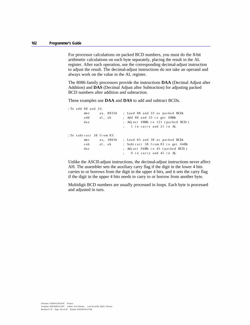
162 Programmer’s Guide
Filename: LMAPGC06.DOC Project: Template: MSGRIDA1.DOT Author: Terri Sharkey Last Saved By: Ruth L Silverio Revision #: 59 Page: 162 of 28 Printed: 10/02/00 04:23 PM
For processor calculations on packed BCD numbers, you must do the 8-bit arithmetic calculations on each byte separately, placing the result in the AL register. After each operation, use the corresponding decimal-adjust instruction to adjust the result. The decimal-adjust instructions do not take an operand and always work on the value in the AL register.
The 8086-family processors provide the instructions DAA (Decimal Adjust after Addition) and DAS (Decimal Adjust after Subtraction) for adjusting packed BCD numbers after addition and subtraction.
These examples use DAA and DAS to add and subtract BCDs.
;To add 88 and 33: mov ax, 8833h ; Load 88 and 33 as packed BCDs add al, ah ; Add 88 and 33 to get 0BBh daa ; Adjust 0BBh to 121 (packed BCD:) ; 1 in carry and 21 in AL ;To subtract 38 from 83: mov ax, 3883h ; Load 83 and 38 as packed BCDs sub al, ah ; Subtract 38 from 83 to get 04Bh das ; Adjust 04Bh to 45 (packed BCD:) ; 0 in carry and 45 in AL
Unlike the ASCII-adjust instructions, the decimal-adjust instructions never affect AH. The assembler sets the auxiliary carry flag if the digit in the lower 4 bits carries to or borrows from the digit in the upper 4 bits, and it sets the carry flag if the digit in the upper 4 bits needs to carry to or borrow from another byte.
Multidigit BCD numbers are usually processed in loops. Each byte is processed and adjusted in turn.
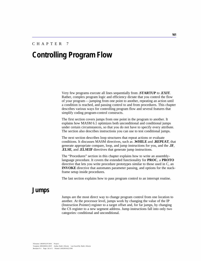
161
Filename: LMAPGC07.DOC Project: Template: MSGRIDA1.DOT Author: Ruth L Silverio Last Saved By: Ruth L Silverio Revision #: 4 Page: 161 of 1 Printed: 10/02/00 04:23 PM
C H A P T E R 7
Very few programs execute all lines sequentially from .STARTUP to .EXIT. Rather, complex program logic and efficiency dictate that you control the flow of your program — jumping from one point to another, repeating an action until a condition is reached, and passing control to and from procedures. This chapter describes various ways for controlling program flow and several features that simplify coding program-control constructs.
The first section covers jumps from one point in the program to another. It explains how MASM 6.1 optimizes both unconditional and conditional jumps under certain circumstances, so that you do not have to specify every attribute. The section also describes instructions you can use to test conditional jumps.
The next section describes loop structures that repeat actions or evaluate conditions. It discusses MASM directives, such as .WHILE and .REPEAT, that generate appropriate compare, loop, and jump instructions for you, and the .IF, .ELSE, and .ELSEIF directives that generate jump instructions.
The “Procedures” section in this chapter explains how to write an assembly-language procedure. It covers the extended functionality for PROC, a PROTO directive that lets you write procedure prototypes similar to those used in C, an INVOKE directive that automates parameter passing, and options for the stack-frame setup inside procedures.
The last section explains how to pass program control to an interrupt routine.
Jumps Jumps are the most direct way to change program control from one location to another. At the processor level, jumps work by changing the value of the IP (Instruction Pointer) register to a target offset and, for far jumps, by changing the CS register to a new segment address. Jump instructions fall into only two categories: conditional and unconditional.
Controlling Program Flow
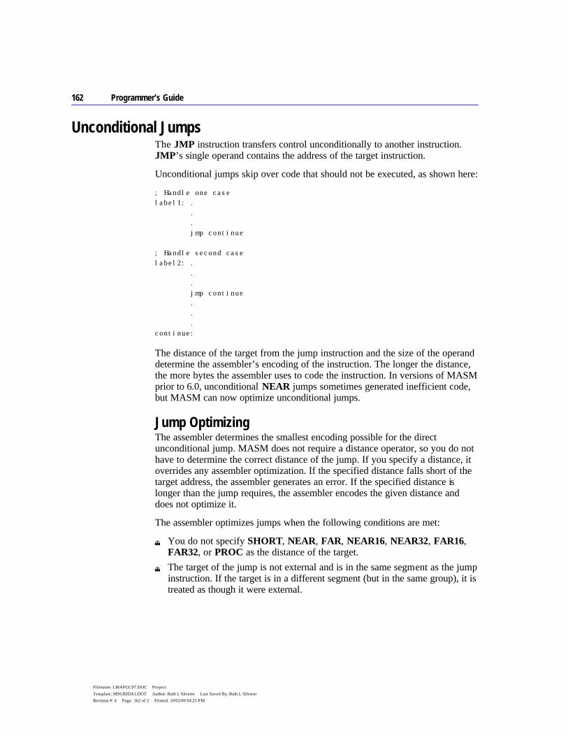
162 Programmer’s Guide
Filename: LMAPGC07.DOC Project: Template: MSGRIDA1.DOT Author: Ruth L Silverio Last Saved By: Ruth L Silverio Revision #: 4 Page: 162 of 2 Printed: 10/02/00 04:23 PM
Unconditional Jumps The JMP instruction transfers control unconditionally to another instruction. JMP’s single operand contains the address of the target instruction.
Unconditional jumps skip over code that should not be executed, as shown here:
; Handle one case label1: . . . jmp continue ; Handle second case label2: . . . jmp continue . . . continue:
The distance of the target from the jump instruction and the size of the operand determine the assembler’s encoding of the instruction. The longer the distance, the more bytes the assembler uses to code the instruction. In versions of MASM prior to 6.0, unconditional NEAR jumps sometimes generated inefficient code, but MASM can now optimize unconditional jumps.
Jump Optimizing The assembler determines the smallest encoding possible for the direct unconditional jump. MASM does not require a distance operator, so you do not have to determine the correct distance of the jump. If you specify a distance, it overrides any assembler optimization. If the specified distance falls short of the target address, the assembler generates an error. If the specified distance is longer than the jump requires, the assembler encodes the given distance and does not optimize it.
The assembler optimizes jumps when the following conditions are met:
u You do not specify SHORT, NEAR, FAR, NEAR16, NEAR32, FAR16, FAR32, or PROC as the distance of the target.
u The target of the jump is not external and is in the same segment as the jump instruction. If the target is in a different segment (but in the same group), it is treated as though it were external.

Chapter 7 Controlling Program Flow 163
Filename: LMAPGC07.DOC Project: Template: MSGRIDA1.DOT Author: Ruth L Silverio Last Saved By: Ruth L Silverio Revision #: 4 Page: 163 of 3 Printed: 10/02/00 04:23 PM
If these two conditions are met, MASM uses the instruction, distance, and size of the operand to determine how to optimize the encoding for the jump. No syntax changes are necessary.
This information about jump optimizing also applies to conditional jumps on the 80386/486.
Indirect Operands An indirect operand provides a pointer to the target address, rather than the address itself. A pointer is a variable that contains an address. The processor distinguishes indirect (pointer) operands from direct (address) operands by the instruction’s context.
You can specify the pointer’s size with the WORD, DWORD, or FWORD attributes. Default sizes are based on .MODEL and the default segment size.
jmp [bx] ; Uses .MODEL and segment size defaults jmp WORD PTR [bx] ; A NEAR16 indirect call
If the indirect operand is a register, the jump is always a NEAR16 jump for a 16-bit register, and NEAR32 for a 32-bit register:
jmp bx ; NEAR16 jump jmp ebx ; NEAR32 jump
A DWORD indirect operand, however, is ambiguous to the assembler.
jmp DWORD PTR [var] ; A NEAR32 jump in a 32-bit segment; ; a FAR16 jump in a 16-bit segment
In this case, your code must clear the ambiguity with the NEAR32 or FAR16 keywords. The following example shows how to use TYPEDEF to define NEAR32 and FAR16 pointer types.
NFP TYPEDEF PTR NEAR32 FFP TYPEDEF PTR FAR16 jmp NFP PTR [var] ; NEAR32 indirect jump jmp FFP PTR [var] ; FAR16 indirect jump
You can use an unconditional jump as a form of conditional jump by specifying the address in a register or indirect memory operand. Also, you can use indirect memory operands to construct jump tables that work like C switch statements, Pascal CASE statements, or Basic ON GOTO, ON GOSUB, or SELECT CASE statements, as shown in the following example.
Note
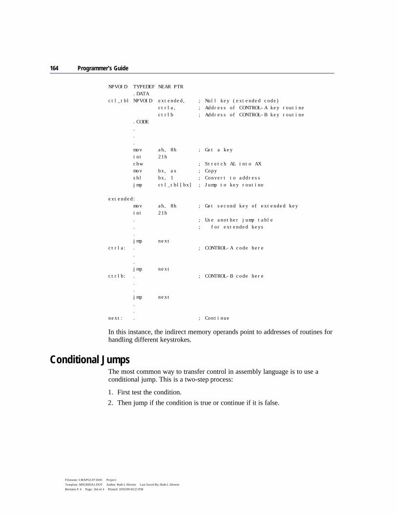
164 Programmer’s Guide
Filename: LMAPGC07.DOC Project: Template: MSGRIDA1.DOT Author: Ruth L Silverio Last Saved By: Ruth L Silverio Revision #: 4 Page: 164 of 4 Printed: 10/02/00 04:23 PM
NPVOID TYPEDEF NEAR PTR .DATA ctl_tbl NPVOID extended, ; Null key (extended code) ctrla, ; Address of CONTROL-A key routine ctrlb ; Address of CONTROL-B key routine .CODE . . . mov ah, 8h ; Get a key int 21h cbw ; Stretch AL into AX mov bx, ax ; Copy shl bx, 1 ; Convert to address jmp ctl_tbl[bx] ; Jump to key routine extended: mov ah, 8h ; Get second key of extended key int 21h . ; Use another jump table . ; for extended keys . jmp next ctrla: . ; CONTROL-A code here . . jmp next ctrlb: . ; CONTROL-B code here . . jmp next . . next: . ; Continue
In this instance, the indirect memory operands point to addresses of routines for handling different keystrokes.
Conditional Jumps The most common way to transfer control in assembly language is to use a conditional jump. This is a two-step process:
1. First test the condition. 2. Then jump if the condition is true or continue if it is false.
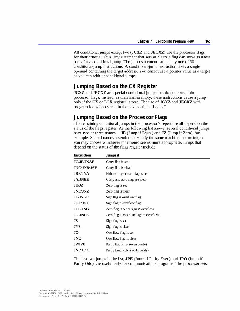
Chapter 7 Controlling Program Flow 165
Filename: LMAPGC07.DOC Project: Template: MSGRIDA1.DOT Author: Ruth L Silverio Last Saved By: Ruth L Silverio Revision #: 4 Page: 165 of 5 Printed: 10/02/00 04:23 PM
All conditional jumps except two (JCXZ and JECXZ) use the processor flags for their criteria. Thus, any statement that sets or clears a flag can serve as a test basis for a conditional jump. The jump statement can be any one of 30 conditional-jump instructions. A conditional-jump instruction takes a single operand containing the target address. You cannot use a pointer value as a target as you can with unconditional jumps.
Jumping Based on the CX Register JCXZ and JECXZ are special conditional jumps that do not consult the processor flags. Instead, as their names imply, these instructions cause a jump only if the CX or ECX register is zero. The use of JCXZ and JECXZ with program loops is covered in the next section, “Loops.”
Jumping Based on the Processor Flags The remaining conditional jumps in the processor’s repertoire all depend on the status of the flags register. As the following list shows, several conditional jumps have two or three names — JE (Jump if Equal) and JZ (Jump if Zero), for example. Shared names assemble to exactly the same machine instruction, so you may choose whichever mnemonic seems more appropriate. Jumps that depend on the status of the flags register include:
Instruction Jumps if
JC/JB/JNAE Carry flag is set JNC/JNB/JAE Carry flag is clear JBE/JNA Either carry or zero flag is set JA/JNBE Carry and zero flag are clear JE/JZ Zero flag is set JNE/JNZ Zero flag is clear JL/JNGE Sign flag ≠ overflow flag JGE/JNL Sign flag = overflow flag JLE/JNG Zero flag is set or sign ≠ overflow JG/JNLE Zero flag is clear and sign = overflow JS Sign flag is set JNS Sign flag is clear JO Overflow flag is set JNO Overflow flag is clear JP/JPE Parity flag is set (even parity) JNP/JPO Parity flag is clear (odd parity)
The last two jumps in the list, JPE (Jump if Parity Even) and JPO (Jump if Parity Odd), are useful only for communications programs. The processor sets
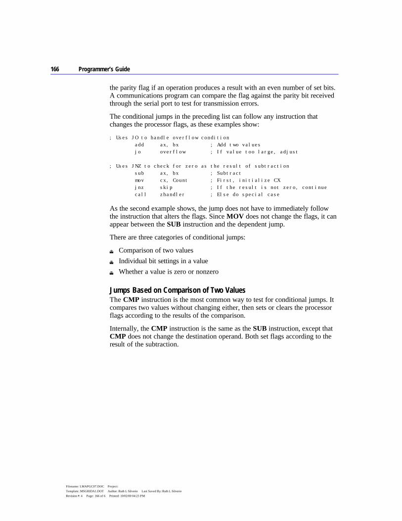
166 Programmer’s Guide
Filename: LMAPGC07.DOC Project: Template: MSGRIDA1.DOT Author: Ruth L Silverio Last Saved By: Ruth L Silverio Revision #: 4 Page: 166 of 6 Printed: 10/02/00 04:23 PM
the parity flag if an operation produces a result with an even number of set bits. A communications program can compare the flag against the parity bit received through the serial port to test for transmission errors.
The conditional jumps in the preceding list can follow any instruction that changes the processor flags, as these examples show:
; Uses JO to handle overflow condition add ax, bx ; Add two values jo overflow ; If value too large, adjust ; Uses JNZ to check for zero as the result of subtraction sub ax, bx ; Subtract mov cx, Count ; First, initialize CX jnz skip ; If the result is not zero, continue call zhandler ; Else do special case
As the second example shows, the jump does not have to immediately follow the instruction that alters the flags. Since MOV does not change the flags, it can appear between the SUB instruction and the dependent jump.
There are three categories of conditional jumps:
u Comparison of two values u Individual bit settings in a value u Whether a value is zero or nonzero
Jumps Based on Comparison of Two Values The CMP instruction is the most common way to test for conditional jumps. It compares two values without changing either, then sets or clears the processor flags according to the results of the comparison.
Internally, the CMP instruction is the same as the SUB instruction, except that CMP does not change the destination operand. Both set flags according to the result of the subtraction.
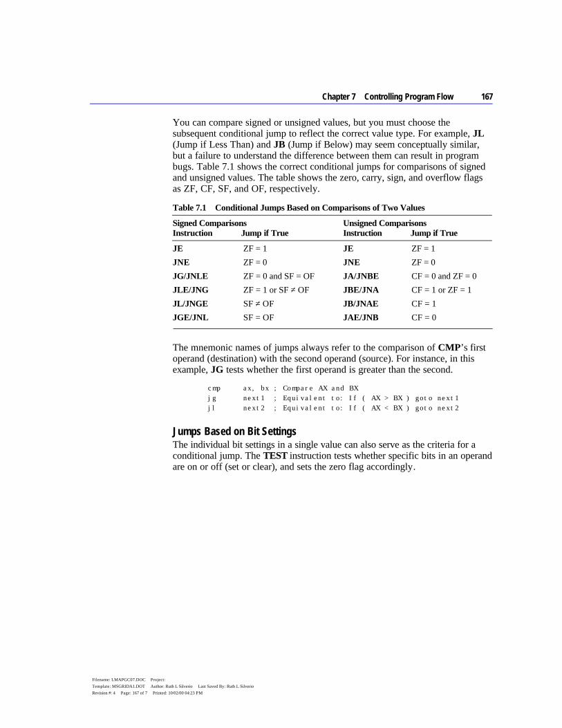
Chapter 7 Controlling Program Flow 167
Filename: LMAPGC07.DOC Project: Template: MSGRIDA1.DOT Author: Ruth L Silverio Last Saved By: Ruth L Silverio Revision #: 4 Page: 167 of 7 Printed: 10/02/00 04:23 PM
You can compare signed or unsigned values, but you must choose the subsequent conditional jump to reflect the correct value type. For example, JL (Jump if Less Than) and JB (Jump if Below) may seem conceptually similar, but a failure to understand the difference between them can result in program bugs. Table 7.1 shows the correct conditional jumps for comparisons of signed and unsigned values. The table shows the zero, carry, sign, and overflow flags as ZF, CF, SF, and OF, respectively.
Table 7.1 Conditional Jumps Based on Comparisons of Two Values
Signed Comparisons Instruction Jump if True
Unsigned Comparisons Instruction Jump if True
JE ZF = 1 JE ZF = 1 JNE ZF = 0 JNE ZF = 0 JG/JNLE ZF = 0 and SF = OF JA/JNBE CF = 0 and ZF = 0 JLE/JNG ZF = 1 or SF ≠ OF JBE/JNA CF = 1 or ZF = 1 JL/JNGE SF ≠ OF JB/JNAE CF = 1 JGE/JNL SF = OF JAE/JNB CF = 0
The mnemonic names of jumps always refer to the comparison of CMP’s first operand (destination) with the second operand (source). For instance, in this example, JG tests whether the first operand is greater than the second.
cmp ax, bx ; Compare AX and BX jg next1 ; Equivalent to: If ( AX > BX ) goto next1 jl next2 ; Equivalent to: If ( AX < BX ) goto next2
Jumps Based on Bit Settings The individual bit settings in a single value can also serve as the criteria for a conditional jump. The TEST instruction tests whether specific bits in an operand are on or off (set or clear), and sets the zero flag accordingly.
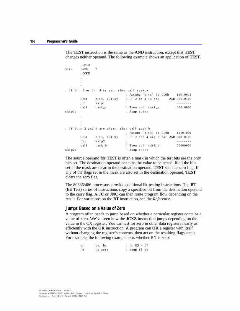
168 Programmer’s Guide
Filename: LMAPGC07.DOC Project: Template: MSGRIDA1.DOT Author: Ruth L Silverio Last Saved By: Ruth L Silverio Revision #: 4 Page: 168 of 8 Printed: 10/02/00 04:23 PM
The TEST instruction is the same as the AND instruction, except that TEST changes neither operand. The following example shows an application of TEST.
.DATA bits BYTE ? .CODE . . . ; If bit 2 or bit 4 is set, then call task_a ; Assume "bits" is 0D3h 11010011 test bits, 10100y ; If 2 or 4 is set AND 00010100 jz skip1 ; -------- call task_a ; Then call task_a 00010000 skip1: ; Jump taken . . . ; If bits 2 and 4 are clear, then call task_b ; Assume "bits" is 0E9h 11101001 test bits, 10100y ; If 2 and 4 are clear AND 00010100 jnz skip2 ; -------- call task_b ; Then call task_b 00000000 skip2: ; Jump taken
The source operand for TEST is often a mask in which the test bits are the only bits set. The destination operand contains the value to be tested. If all the bits set in the mask are clear in the destination operand, TEST sets the zero flag. If any of the flags set in the mask are also set in the destination operand, TEST clears the zero flag.
The 80386/486 processors provide additional bit-testing instructions. The BT (Bit Test) series of instructions copy a specified bit from the destination operand to the carry flag. A JC or JNC can then route program flow depending on the result. For variations on the BT instruction, see the Reference.
Jumps Based on a Value of Zero A program often needs to jump based on whether a particular register contains a value of zero. We’ve seen how the JCXZ instruction jumps depending on the value in the CX register. You can test for zero in other data registers nearly as efficiently with the OR instruction. A program can OR a register with itself without changing the register’s contents, then act on the resulting flags status. For example, the following example tests whether BX is zero:
or bx, bx ; Is BX = 0? jz is_zero ; Jump if so
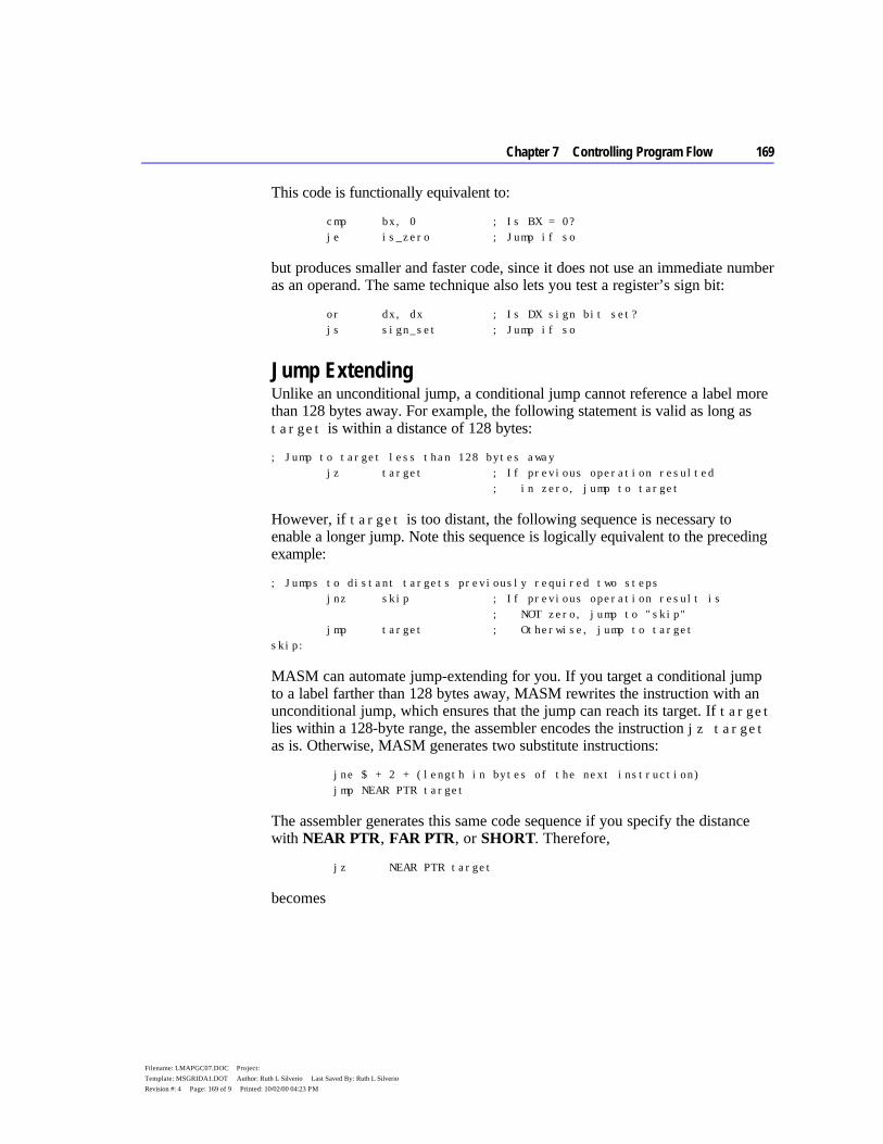
Chapter 7 Controlling Program Flow 169
Filename: LMAPGC07.DOC Project: Template: MSGRIDA1.DOT Author: Ruth L Silverio Last Saved By: Ruth L Silverio Revision #: 4 Page: 169 of 9 Printed: 10/02/00 04:23 PM
This code is functionally equivalent to:
cmp bx, 0 ; Is BX = 0? je is_zero ; Jump if so
but produces smaller and faster code, since it does not use an immediate number as an operand. The same technique also lets you test a register’s sign bit:
or dx, dx ; Is DX sign bit set? js sign_set ; Jump if so
Jump Extending Unlike an unconditional jump, a conditional jump cannot reference a label more than 128 bytes away. For example, the following statement is valid as long as target is within a distance of 128 bytes:
; Jump to target less than 128 bytes away jz target ; If previous operation resulted ; in zero, jump to target
However, if target is too distant, the following sequence is necessary to enable a longer jump. Note this sequence is logically equivalent to the preceding example:
; Jumps to distant targets previously required two steps jnz skip ; If previous operation result is ; NOT zero, jump to "skip" jmp target ; Otherwise, jump to target skip:
MASM can automate jump-extending for you. If you target a conditional jump to a label farther than 128 bytes away, MASM rewrites the instruction with an unconditional jump, which ensures that the jump can reach its target. If target lies within a 128-byte range, the assembler encodes the instruction jz target as is. Otherwise, MASM generates two substitute instructions:
jne $ + 2 + (length in bytes of the next instruction) jmp NEAR PTR target
The assembler generates this same code sequence if you specify the distance with NEAR PTR, FAR PTR, or SHORT. Therefore,
jz NEAR PTR target
becomes
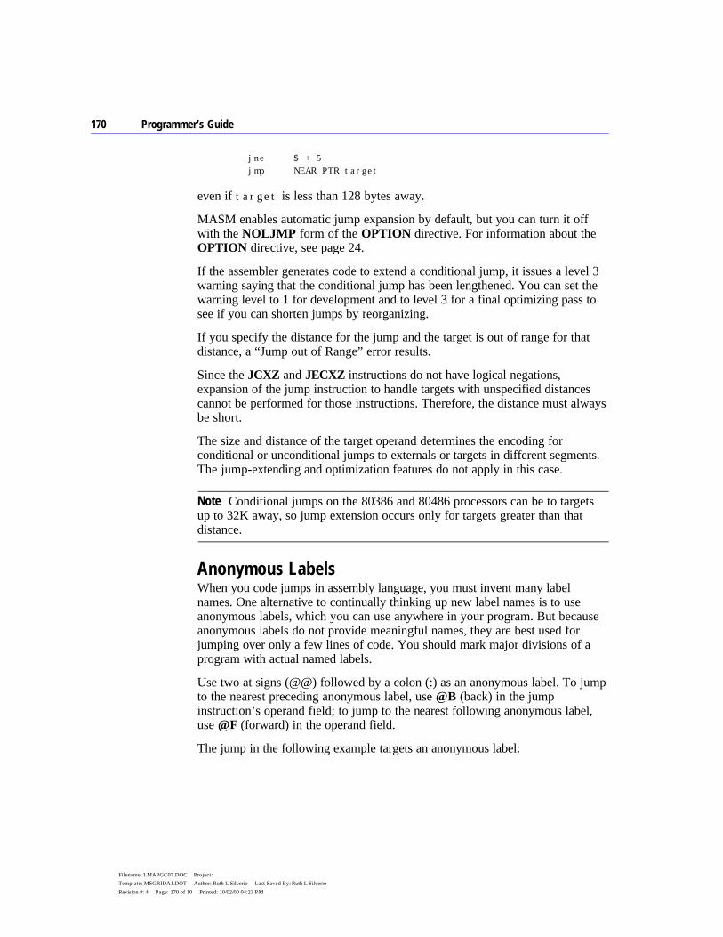
170 Programmer’s Guide
Filename: LMAPGC07.DOC Project: Template: MSGRIDA1.DOT Author: Ruth L Silverio Last Saved By: Ruth L Silverio Revision #: 4 Page: 170 of 10 Printed: 10/02/00 04:23 PM
jne $ + 5 jmp NEAR PTR target
even if target is less than 128 bytes away.
MASM enables automatic jump expansion by default, but you can turn it off with the NOLJMP form of the OPTION directive. For information about the OPTION directive, see page 24.
If the assembler generates code to extend a conditional jump, it issues a level 3 warning saying that the conditional jump has been lengthened. You can set the warning level to 1 for development and to level 3 for a final optimizing pass to see if you can shorten jumps by reorganizing.
If you specify the distance for the jump and the target is out of range for that distance, a “Jump out of Range” error results.
Since the JCXZ and JECXZ instructions do not have logical negations, expansion of the jump instruction to handle targets with unspecified distances cannot be performed for those instructions. Therefore, the distance must always be short.
The size and distance of the target operand determines the encoding for conditional or unconditional jumps to externals or targets in different segments. The jump-extending and optimization features do not apply in this case.
Conditional jumps on the 80386 and 80486 processors can be to targets up to 32K away, so jump extension occurs only for targets greater than that distance.
Anonymous Labels When you code jumps in assembly language, you must invent many label names. One alternative to continually thinking up new label names is to use anonymous labels, which you can use anywhere in your program. But because anonymous labels do not provide meaningful names, they are best used for jumping over only a few lines of code. You should mark major divisions of a program with actual named labels.
Use two at signs (@@) followed by a colon (:) as an anonymous label. To jump to the nearest preceding anonymous label, use @B (back) in the jump instruction’s operand field; to jump to the nearest following anonymous label, use @F (forward) in the operand field.
The jump in the following example targets an anonymous label:
Note
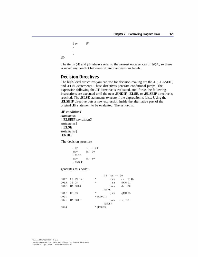
Chapter 7 Controlling Program Flow 171
Filename: LMAPGC07.DOC Project: Template: MSGRIDA1.DOT Author: Ruth L Silverio Last Saved By: Ruth L Silverio Revision #: 4 Page: 171 of 11 Printed: 10/02/00 04:23 PM
jge @F . . . @@:
The items @B and @F always refer to the nearest occurrences of @@:, so there is never any conflict between different anonymous labels.
Decision Directives The high-level structures you can use for decision-making are the .IF, .ELSEIF, and .ELSE statements. These directives generate conditional jumps. The expression following the .IF directive is evaluated, and if true, the following instructions are executed until the next .ENDIF, .ELSE, or .ELSEIF directive is reached. The .ELSE statements execute if the expression is false. Using the .ELSEIF directive puts a new expression inside the alternative part of the original .IF statement to be evaluated. The syntax is:
.IF condition1 statements [[.ELSEIF condition2 statements]] [[.ELSE statements]] .ENDIF
The decision structure
.IF cx == 20 mov dx, 20 .ELSE mov dx, 30 .ENDIF
generates this code:
.IF cx == 20 0017 83 F9 14 * cmp cx, 014h 001A 75 05 * jne @C0001 001C BA 0014 mov dx, 20 .ELSE 001F EB 03 * jmp @C0003 0021 *@C0001: 0021 BA 001E mov dx, 30 .ENDIF 0024 *@C0003:
172 Programmer’s Guide
Filename: LMAPGC07.DOC Project: Template: MSGRIDA1.DOT Author: Ruth L Silverio Last Saved By: Ruth L Silverio Revision #: 4 Page: 172 of 12 Printed: 10/02/00 04:23 PM
Loops Loops repeat an action until a termination condition is reached. This condition can be a counter or the result of an expression’s evaluation. MASM 6.1 offers many ways to set up loops in your programs. The following list compares MASM loop structures:
Instructions Action
LOOP Automatically decrements CX. When CX = 0, the loop ends. The top of the loop cannot be greater than 128 bytes from the LOOP instruction. (This is true for all LOOP instructions.)
LOOPE/LOOPZ, LOOPNE/LOOPNZ
Loops while equal or not equal. Checks both CX and the state of the zero flag. LOOPZ ends when either CX=0 or the zero flag is clear, whichever occurs first. LOOPNZ ends when either CX=0 or the zero flag is set, whichever occurs first. LOOPE and LOOPZ assemble to the same machine instruction, as do LOOPNE and LOOPNZ. Use whichever mnemonic best fits the context of your loop. Set CX to a number out of range if you don’t want a count to control the loop.
JCXZ, JECXZ Branches to a label only if CX = 0 or ECX = 0. Unlike other conditional-jump instructions, which can jump to either a near or a short label under the 80386 or 80486, JCXZ and JECXZ always jump to a short label.
Conditional jumps Acts only if certain conditions met. Necessary if several conditions must be tested. See “Conditional Jumps,” page 164.
The following examples illustrate these loop constructions.
; The LOOP instruction: For 200 to 0 do task mov cx, 200 ; Set counter next: . ; Do the task here . . loop next ; Do again ; Continue after loop ; The LOOPNE instruction: While AX is not 'Y', do task mov cx, 256 ; Set count too high to interfere wend: . ; But don't do more than 256 times . ; Some statements that change AX . cmp al, 'Y' ; Is it Y or too many times? loopne wend ; No? Repeat ; Yes? Continue
The JCXZ and JECXZ instructions provide an efficient way to avoid executing loops when the loop counter CX is empty. For example, consider the following loops:
Chapter 7 Controlling Program Flow 173
Filename: LMAPGC07.DOC Project: Template: MSGRIDA1.DOT Author: Ruth L Silverio Last Saved By: Ruth L Silverio Revision #: 4 Page: 173 of 13 Printed: 10/02/00 04:23 PM
mov cx, LoopCount ; Load loop counter next: . ; Iterate loop CX times . . loop next ; Do again
If LoopCount is zero, CX decrements to -1 on the first pass. It then must decrement 65,535 more times before reaching 0. Use a JCXZ to avoid this problem:
mov cx, LoopCount ; Load loop counter jcxz done ; Skip loop if count is 0 next: . ; Else iterate loop CX times . . loop next ; Do again done: ; Continue after loop
Loop-Generating Directives The high-level control structures generate loop structures for you. These directives are similar to the while and repeat loops of C or Pascal, and can make your assembly programs easier to code and to read. The assembler generates the appropriate assembly code. These directives are summarized as follows:
Directives Action
.WHILE ... .ENDW The statements between .WHILE condition and .ENDW execute while the condition is true.
.REPEAT ... .UNTIL The loop executes at least once and continues until the condition given after .UNTIL is true. Generates conditional jumps.
.REPEAT ... .UNTILCXZ Compares label to an expression and generates appropriate loop instructions.
.BREAK End a .REPEAT or a .WHILE loop unconditionally.
.CONTINUE Jump unconditionally past any remaining code to bottom of loop.

174 Programmer’s Guide
Filename: LMAPGC07.DOC Project: Template: MSGRIDA1.DOT Author: Ruth L Silverio Last Saved By: Ruth L Silverio Revision #: 4 Page: 174 of 14 Printed: 10/02/00 04:23 PM
These constructs work much as they do in a high-level language such as C or Pascal. Keep in mind the following points:
u These directives generate appropriate processor instructions. They are not new instructions.
u They require proper use of signed and unsigned data declarations.
These directives cause a set of instructions to execute based on the evaluation of some condition. This condition can be an expression that evaluates to a signed or unsigned value, an expression using the binary operators in C (&&, ||, or !), or the state of a flag. For more information about expression operators, see page 178.
The evaluation of the condition requires the assembler to know if the operands in the condition are signed or unsigned. To state explicitly that a named memory location contains a signed integer, use the signed data allocation directives SBYTE, SWORD, and SDWORD.
.WHILE Loops As with while loops in C or Pascal, the test condition for .WHILE is checked before the statements inside the loop execute. If the test condition is false, the loop does not execute. While the condition is true, the statements inside the loop repeat.
Use the .ENDW directive to mark the end of the .WHILE loop. When the condition becomes false, program execution begins at the first statement following the .ENDW directive. The .WHILE directive generates appropriate compare and jump statements. The syntax is:
.WHILE condition statements .ENDW
For example, this loop copies the contents of one buffer to another until a ‘$’ character (marking the end of the string) is found:
.DATA buf1 BYTE "This is a string",'$' buf2 BYTE 100 DUP (?) .CODE sub bx, bx ; Zero out bx .WHILE (buf1[bx] != '$') mov al, buf1[bx] ; Get a character mov buf2[bx], al ; Move it to buffer 2 inc bx ; Count forward .ENDW
Chapter 7 Controlling Program Flow 175
Filename: LMAPGC07.DOC Project: Template: MSGRIDA1.DOT Author: Ruth L Silverio Last Saved By: Ruth L Silverio Revision #: 4 Page: 175 of 15 Printed: 10/02/00 04:23 PM
.REPEAT Loops MASM’s .REPEAT directive allows for loop constructions like the do loop of C and the REPEAT loop of Pascal. The loop executes until the condition following the .UNTIL (or .UNTILCXZ) directive becomes true. Since the condition is checked at the end of the loop, the loop always executes at least once. The .REPEAT directive generates conditional jumps. The syntax is:
.REPEAT statements .UNTIL condition
.REPEAT statements .UNTILCXZ [[condition]]
where condition can also be expr1 == expr2 or expr1 != expr2. When two conditions are used, expr2 can be an immediate expression, a register, or (if expr1 is a register) a memory location.
For example, the following code fills a buffer with characters typed at the keyboard. The loop ends when the ENTER key (character 13) is pressed:
.DATA buffer BYTE 100 DUP (0) .CODE sub bx, bx ; Zero out bx .REPEAT mov ah, 01h int 21h ; Get a key mov buffer[bx], al ; Put it in the buffer inc bx ; Increment the count .UNTIL (al == 13) ; Continue until al is 13
176 Programmer’s Guide
Filename: LMAPGC07.DOC Project: Template: MSGRIDA1.DOT Author: Ruth L Silverio Last Saved By: Ruth L Silverio Revision #: 4 Page: 176 of 16 Printed: 10/02/00 04:23 PM
The .UNTIL directive generates conditional jumps, but the .UNTILCXZ directive generates a LOOP instruction, as shown by the listing file code for these examples. In a listing file, assembler-generated code is preceded by an asterisk.
ASSUME bx:PTR SomeStruct .REPEAT *@C0001: inc ax .UNTIL ax==6 * cmp ax, 006h * jne @C0001 .REPEAT *@C0003: mov ax, 1 .UNTILCXZ * loop @C0003 .REPEAT *@C0004: .UNTILCXZ [bx].field != 6 * cmp [bx].field, 006h * loope @C0004
.BREAK and .CONTINUE Directives The .BREAK and .CONTINUE directives terminate a .REPEAT or .WHILE loop prematurely. These directives allow an optional .IF clause for conditional breaks. The syntax is:
.BREAK [[.IF condition]]
.CONTINUE [[.IF condition]]
Note that .ENDIF is not used with the .IF forms of .BREAK and .CONTINUE in this context. The .BREAK and .CONTINUE directives work the same way as the break and continue instructions in C. Execution continues at the instruction following the .UNTIL, .UNTILCXZ, or .ENDW of the nearest enclosing loop.
Instead of ending the loop execution as .BREAK does, .CONTINUE causes loop execution to jump directly to the code that evaluates the loop condition of the nearest enclosing loop.
The following loop accepts only the keys in the range ‘0’ to ‘9’ and terminates when you press ENTER.
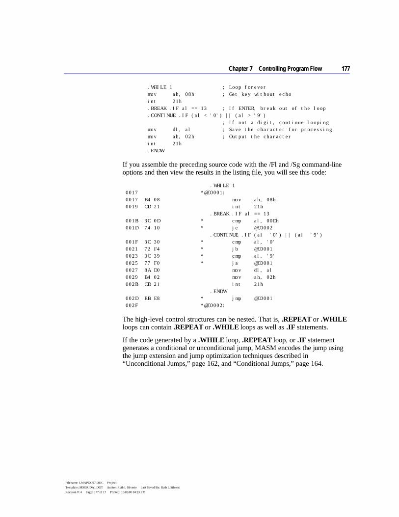
Chapter 7 Controlling Program Flow 177
Filename: LMAPGC07.DOC Project: Template: MSGRIDA1.DOT Author: Ruth L Silverio Last Saved By: Ruth L Silverio Revision #: 4 Page: 177 of 17 Printed: 10/02/00 04:23 PM
.WHILE 1 ; Loop forever mov ah, 08h ; Get key without echo int 21h .BREAK .IF al == 13 ; If ENTER, break out of the loop .CONTINUE .IF (al < '0') || (al > '9') ; If not a digit, continue looping mov dl, al ; Save the character for processing mov ah, 02h ; Output the character int 21h .ENDW
If you assemble the preceding source code with the /Fl and /Sg command-line options and then view the results in the listing file, you will see this code:
.WHILE 1 0017 *@C0001: 0017 B4 08 mov ah, 08h 0019 CD 21 int 21h .BREAK .IF al == 13 001B 3C 0D * cmp al, 00Dh 001D 74 10 * je @C0002 .CONTINUE .IF (al '0') || (al '9') 001F 3C 30 * cmp al, '0' 0021 72 F4 * jb @C0001 0023 3C 39 * cmp al, '9' 0025 77 F0 * ja @C0001 0027 8A D0 mov dl, al 0029 B4 02 mov ah, 02h 002B CD 21 int 21h .ENDW 002D EB E8 * jmp @C0001 002F *@C0002:
The high-level control structures can be nested. That is, .REPEAT or .WHILE loops can contain .REPEAT or .WHILE loops as well as .IF statements.
If the code generated by a .WHILE loop, .REPEAT loop, or .IF statement generates a conditional or unconditional jump, MASM encodes the jump using the jump extension and jump optimization techniques described in “Unconditional Jumps,” page 162, and “Conditional Jumps,” page 164.
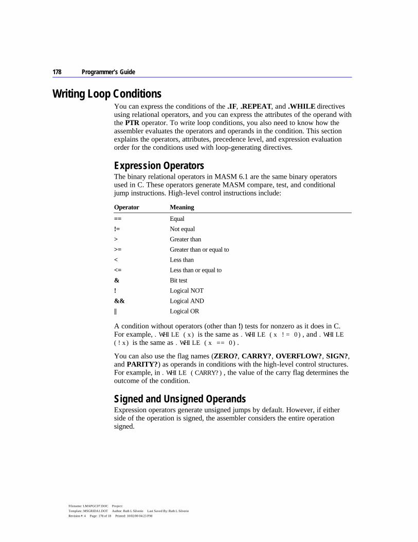
178 Programmer’s Guide
Filename: LMAPGC07.DOC Project: Template: MSGRIDA1.DOT Author: Ruth L Silverio Last Saved By: Ruth L Silverio Revision #: 4 Page: 178 of 18 Printed: 10/02/00 04:23 PM
Writing Loop Conditions You can express the conditions of the .IF, .REPEAT, and .WHILE directives using relational operators, and you can express the attributes of the operand with the PTR operator. To write loop conditions, you also need to know how the assembler evaluates the operators and operands in the condition. This section explains the operators, attributes, precedence level, and expression evaluation order for the conditions used with loop-generating directives.
Expression Operators The binary relational operators in MASM 6.1 are the same binary operators used in C. These operators generate MASM compare, test, and conditional jump instructions. High-level control instructions include:
Operator Meaning
== Equal != Not equal > Greater than >= Greater than or equal to < Less than <= Less than or equal to & Bit test ! Logical NOT && Logical AND || Logical OR
A condition without operators (other than !) tests for nonzero as it does in C. For example, .WHILE (x) is the same as .WHILE (x != 0), and .WHILE (!x) is the same as .WHILE (x == 0).
You can also use the flag names (ZERO?, CARRY?, OVERFLOW?, SIGN?, and PARITY?) as operands in conditions with the high-level control structures. For example, in .WHILE (CARRY?), the value of the carry flag determines the outcome of the condition.
Signed and Unsigned Operands Expression operators generate unsigned jumps by default. However, if either side of the operation is signed, the assembler considers the entire operation signed.

Chapter 7 Controlling Program Flow 179
Filename: LMAPGC07.DOC Project: Template: MSGRIDA1.DOT Author: Ruth L Silverio Last Saved By: Ruth L Silverio Revision #: 4 Page: 179 of 19 Printed: 10/02/00 04:23 PM
You can use the PTR operator to tell the assembler that a particular operand in a register or constant is a signed number, as in these examples:
.WHILE SWORD PTR [bx] <= 0 .IF SWORD PTR mem1 > 0
Without the PTR operator, the assembler would treat the contents of BX as an unsigned value.
You can also specify the size attributes of operands in memory locations with SBYTE, SWORD, and SDWORD, for use with .IF, .WHILE, and .REPEAT.
.DATA mem1 SBYTE ? mem2 WORD ? .IF mem1 > 0 .WHILE mem2 < bx .WHILE SWORD PTR ax < count
Precedence Level As with C, you can concatenate conditions with the && operator for AND, the || operator for OR, and the ! operator for negate. The precedence level is !, &&, and ||, with ! having the highest priority. Like expressions in high-level languages, precedence is evaluated left to right.
Expression Evaluation The assembler evaluates conditions created with high-level control structures according to short-circuit evaluation. If the evaluation of a particular condition automatically determines the final result (such as a condition that evaluates to false in a compound statement concatenated with AND), the evaluation does not continue.
For example, in this .WHILE statement,
.WHILE (ax > 0) && (WORD PTR [bx] == 0)
the assembler evaluates the first condition. If this condition is false (that is, if AX is less than or equal to 0), the evaluation is finished. The second condition is not checked and the loop does not execute, because a compound condition containing && requires both expressions to be true for the entire condition to be true.
180 Programmer’s Guide
Filename: LMAPGC07.DOC Project: Template: MSGRIDA1.DOT Author: Ruth L Silverio Last Saved By: Ruth L Silverio Revision #: 4 Page: 180 of 20 Printed: 10/02/00 04:23 PM
Procedures Organizing your code into procedures that execute specific tasks divides large programs into manageable units, allows for separate testing, and makes code more efficient for repetitive tasks.
Assembly-language procedures are similar to functions, subroutines, and procedures in high-level languages such as C, FORTRAN, and Pascal. Two instructions control the use of assembly-language procedures. CALL pushes the return address onto the stack and transfers control to a procedure, and RET pops the return address off the stack and returns control to that location.
The PROC and ENDP directives mark the beginning and end of a procedure. Additionally, PROC can automatically:
u Preserve register values that should not change but that the procedure might otherwise alter.
u Set up a local stack pointer, so that you can access parameters and local variables placed on the stack.
u Adjust the stack when the procedure ends.
Defining Procedures Procedures require a label at the start of the procedure and a RET instruction at the end. Procedures are normally defined by using the PROC directive at the start of the procedure and the ENDP directive at the end. The RET instruction normally is placed immediately before the ENDP directive. The assembler makes sure the distance of the RET instruction matches the distance defined by the PROC directive. The basic syntax for PROC is:
label PROC [[NEAR | FAR]] . . . RET [[constant]] label ENDP
The CALL instruction pushes the address of the next instruction in your code onto the stack and passes control to a specified address. The syntax is:
CALL {label | register | memory}
The operand contains a value calculated at run time. Since that operand can be a register, direct memory operand, or indirect memory operand, you can write call tables similar to the example code on page 164.
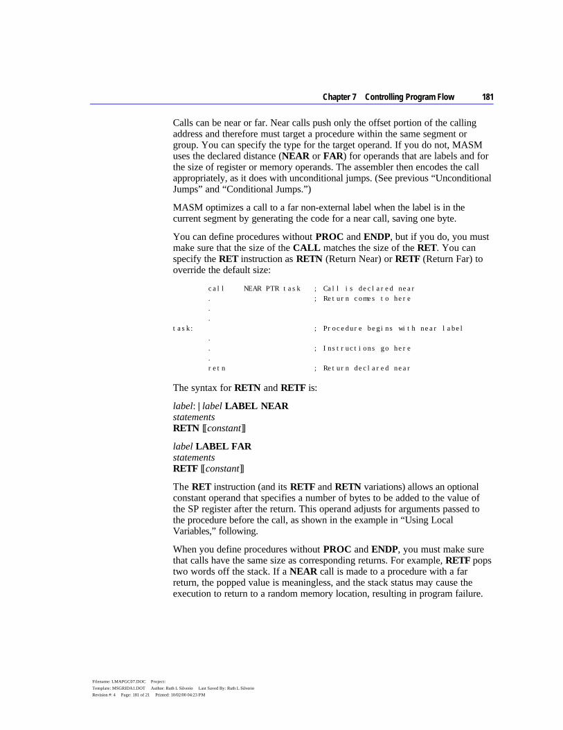
Chapter 7 Controlling Program Flow 181
Filename: LMAPGC07.DOC Project: Template: MSGRIDA1.DOT Author: Ruth L Silverio Last Saved By: Ruth L Silverio Revision #: 4 Page: 181 of 21 Printed: 10/02/00 04:23 PM
Calls can be near or far. Near calls push only the offset portion of the calling address and therefore must target a procedure within the same segment or group. You can specify the type for the target operand. If you do not, MASM uses the declared distance (NEAR or FAR) for operands that are labels and for the size of register or memory operands. The assembler then encodes the call appropriately, as it does with unconditional jumps. (See previous “Unconditional Jumps” and “Conditional Jumps.”)
MASM optimizes a call to a far non-external label when the label is in the current segment by generating the code for a near call, saving one byte.
You can define procedures without PROC and ENDP, but if you do, you must make sure that the size of the CALL matches the size of the RET. You can specify the RET instruction as RETN (Return Near) or RETF (Return Far) to override the default size:
call NEAR PTR task ; Call is declared near . ; Return comes to here . . task: ; Procedure begins with near label . . ; Instructions go here . retn ; Return declared near
The syntax for RETN and RETF is:
label: | label LABEL NEAR statements RETN [[constant]]
label LABEL FAR statements RETF [[constant]]
The RET instruction (and its RETF and RETN variations) allows an optional constant operand that specifies a number of bytes to be added to the value of the SP register after the return. This operand adjusts for arguments passed to the procedure before the call, as shown in the example in “Using Local Variables,” following.
When you define procedures without PROC and ENDP, you must make sure that calls have the same size as corresponding returns. For example, RETF pops two words off the stack. If a NEAR call is made to a procedure with a far return, the popped value is meaningless, and the stack status may cause the execution to return to a random memory location, resulting in program failure.
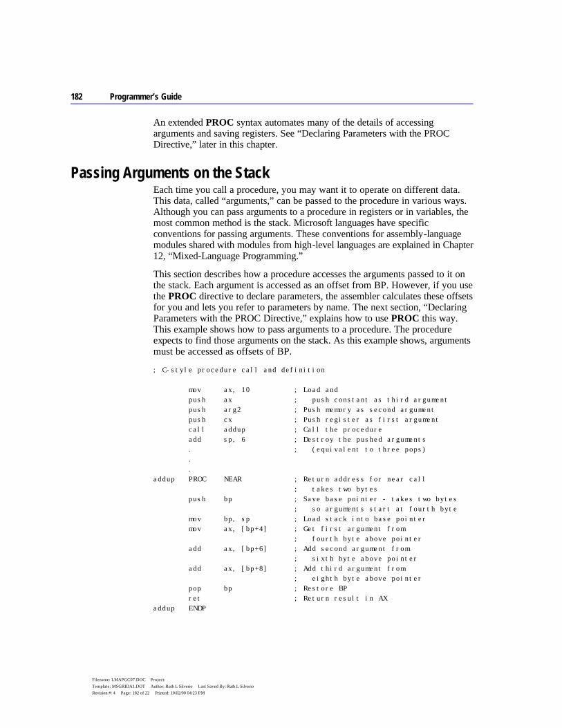
182 Programmer’s Guide
Filename: LMAPGC07.DOC Project: Template: MSGRIDA1.DOT Author: Ruth L Silverio Last Saved By: Ruth L Silverio Revision #: 4 Page: 182 of 22 Printed: 10/02/00 04:23 PM
An extended PROC syntax automates many of the details of accessing arguments and saving registers. See “Declaring Parameters with the PROC Directive,” later in this chapter.
Passing Arguments on the Stack Each time you call a procedure, you may want it to operate on different data. This data, called “arguments,” can be passed to the procedure in various ways. Although you can pass arguments to a procedure in registers or in variables, the most common method is the stack. Microsoft languages have specific conventions for passing arguments. These conventions for assembly-language modules shared with modules from high-level languages are explained in Chapter 12, “Mixed-Language Programming.”
This section describes how a procedure accesses the arguments passed to it on the stack. Each argument is accessed as an offset from BP. However, if you use the PROC directive to declare parameters, the assembler calculates these offsets for you and lets you refer to parameters by name. The next section, “Declaring Parameters with the PROC Directive,” explains how to use PROC this way. This example shows how to pass arguments to a procedure. The procedure expects to find those arguments on the stack. As this example shows, arguments must be accessed as offsets of BP.
; C-style procedure call and definition mov ax, 10 ; Load and push ax ; push constant as third argument push arg2 ; Push memory as second argument push cx ; Push register as first argument call addup ; Call the procedure add sp, 6 ; Destroy the pushed arguments . ; (equivalent to three pops) . . addup PROC NEAR ; Return address for near call ; takes two bytes push bp ; Save base pointer - takes two bytes ; so arguments start at fourth byte mov bp, sp ; Load stack into base pointer mov ax, [bp+4] ; Get first argument from ; fourth byte above pointer add ax, [bp+6] ; Add second argument from ; sixth byte above pointer add ax, [bp+8] ; Add third argument from ; eighth byte above pointer pop bp ; Restore BP ret ; Return result in AX addup ENDP

Chapter 7 Controlling Program Flow 183
Filename: LMAPGC07.DOC Project: Template: MSGRIDA1.DOT Author: Ruth L Silverio Last Saved By: Ruth L Silverio Revision #: 4 Page: 183 of 23 Printed: 10/02/00 04:23 PM
Figure 7.1 shows the stack condition at key points in the process.
Figure 7.1 Procedure Arguments on the Stack
Starting with the 80186 processor, the ENTER and LEAVE instructions simplify the stack setup and restore instructions at the beginning and end of procedures. However, ENTER uses a lot of time. It is necessary only with nested, statically-scoped procedures. Thus, a Pascal compiler may sometimes generate ENTER. The LEAVE instruction, on the other hand, is an efficient way to do the stack cleanup. LEAVE reverses the effect of the last ENTER instruction by restoring BP and SP to their values before the procedure call.

184 Programmer’s Guide
Filename: LMAPGC07.DOC Project: Template: MSGRIDA1.DOT Author: Ruth L Silverio Last Saved By: Ruth L Silverio Revision #: 4 Page: 184 of 24 Printed: 10/02/00 04:23 PM
Declaring Parameters with the PROC Directive With the PROC directive, you can specify registers to be saved, define param- eters to the procedure, and assign symbol names to parameters (rather than as offsets from BP). This section describes how to use the PROC directive to automate the parameter-accessing techniques described in the last section.
For example, the following diagram shows a valid PROC statement for a procedure called from C. It takes two parameters, var1 and arg1, and uses (and must save) the DI and SI registers:
The syntax for PROC is:
label PROC [[attributes]] [[USES reglist]] [[, ]] [[parameter[[:tag]]... ]]
The parts of the PROC directive include:
Argument Description
label The name of the procedure. attributes Any of several attributes of the procedure, including the distance, langtype, and
visibility of the procedure. The syntax for attributes is given on the following page.
reglist A list of registers following the USES keyword that the procedure uses, and that should be saved on entry. Registers in the list must be separated by blanks or tabs, not by commas. The assembler generates prologue code to push these registers onto the stack. When you exit, the assembler generates epilogue code to pop the saved register values off the stack.
parameter The list of parameters passed to the procedure on the stack. The list can have a variable number of parameters. See the discussion following for the syntax of parameter. This list can be longer than one line if the continued line ends with a comma.
This diagram shows a valid PROC definition that uses several attributes:
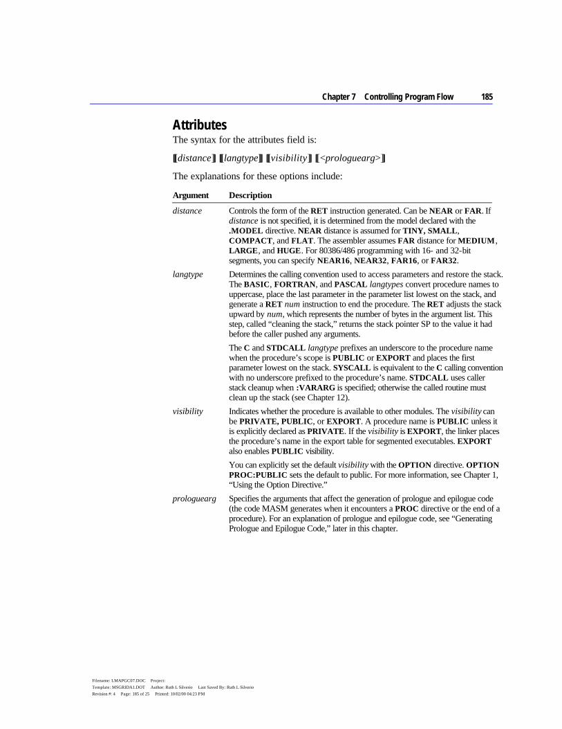
Chapter 7 Controlling Program Flow 185
Filename: LMAPGC07.DOC Project: Template: MSGRIDA1.DOT Author: Ruth L Silverio Last Saved By: Ruth L Silverio Revision #: 4 Page: 185 of 25 Printed: 10/02/00 04:23 PM
Attributes The syntax for the attributes field is:
[[distance]] [[langtype]] [[visibility]] [[<prologuearg>]]
The explanations for these options include:
Argument Description
distance Controls the form of the RET instruction generated. Can be NEAR or FAR. If distance is not specified, it is determined from the model declared with the .MODEL directive. NEAR distance is assumed for TINY, SMALL, COMPACT, and FLAT. The assembler assumes FAR distance for MEDIUM, LARGE, and HUGE. For 80386/486 programming with 16- and 32-bit segments, you can specify NEAR16, NEAR32, FAR16, or FAR32.
langtype Determines the calling convention used to access parameters and restore the stack. The BASIC, FORTRAN, and PASCAL langtypes convert procedure names to uppercase, place the last parameter in the parameter list lowest on the stack, and generate a RET num instruction to end the procedure. The RET adjusts the stack upward by num, which represents the number of bytes in the argument list. This step, called “cleaning the stack,” returns the stack pointer SP to the value it had before the caller pushed any arguments.
The C and STDCALL langtype prefixes an underscore to the procedure name when the procedure’s scope is PUBLIC or EXPORT and places the first parameter lowest on the stack. SYSCALL is equivalent to the C calling convention with no underscore prefixed to the procedure’s name. STDCALL uses caller stack cleanup when :VARARG is specified; otherwise the called routine must clean up the stack (see Chapter 12).
visibility Indicates whether the procedure is available to other modules. The visibility can be PRIVATE, PUBLIC, or EXPORT. A procedure name is PUBLIC unless it is explicitly declared as PRIVATE. If the visibility is EXPORT, the linker places the procedure’s name in the export table for segmented executables. EXPORT also enables PUBLIC visibility.
You can explicitly set the default visibility with the OPTION directive. OPTION PROC:PUBLIC sets the default to public. For more information, see Chapter 1, “Using the Option Directive.”
prologuearg Specifies the arguments that affect the generation of prologue and epilogue code (the code MASM generates when it encounters a PROC directive or the end of a procedure). For an explanation of prologue and epilogue code, see “Generating Prologue and Epilogue Code,” later in this chapter.

186 Programmer’s Guide
Filename: LMAPGC07.DOC Project: Template: MSGRIDA1.DOT Author: Ruth L Silverio Last Saved By: Ruth L Silverio Revision #: 4 Page: 186 of 26 Printed: 10/02/00 04:23 PM
Parameters The comma that separates parameters from reglist is optional, if both fields appear on the same line. If parameters appears on a separate line, you must end the reglist field with a comma. In the syntax:
parmname [[:tag]
parmname is the name of the parameter. The tag can be the qualifiedtype or the keyword VARARG. However, only the last parameter in a list of param- eters can use the VARARG keyword. The qualifiedtype is discussed in “Data Types,” Chapter 1. An example showing how to reference VARARG param- eters appears later in this section. You can nest procedures if they do not have parameters or USES register lists. This diagram shows a procedure definition with one parameter definition.
The procedure presented in “Passing Arguments on the Stack,” page 182, is here rewritten using the extended PROC functionality. Prior to the procedure call, you must push the arguments onto the stack unless you use INVOKE. (See “Calling Procedures with INVOKE,” later in this chapter.)
addup PROC NEAR C, arg1:WORD, arg2:WORD, count:WORD mov ax, arg1 add ax, count add ax, arg2 ret addup ENDP
If the arguments for a procedure are pointers, the assembler does not generate any code to get the value or values that the pointers reference; your program must still explicitly treat the argument as a pointer. (For more information about using pointers, see Chapter 3, “Using Addresses and Pointers.”)
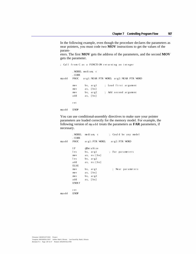
Chapter 7 Controlling Program Flow 187
Filename: LMAPGC07.DOC Project: Template: MSGRIDA1.DOT Author: Ruth L Silverio Last Saved By: Ruth L Silverio Revision #: 4 Page: 187 of 27 Printed: 10/02/00 04:23 PM
In the following example, even though the procedure declares the parameters as near pointers, you must code two MOV instructions to get the values of the param- eters. The first MOV gets the address of the parameters, and the second MOV gets the parameter.
; Call from C as a FUNCTION returning an integer .MODEL medium, c .CODE myadd PROC arg1:NEAR PTR WORD, arg2:NEAR PTR WORD mov bx, arg1 ; Load first argument mov ax, [bx] mov bx, arg2 ; Add second argument add ax, [bx] ret myadd ENDP
You can use conditional-assembly directives to make sure your pointer parameters are loaded correctly for the memory model. For example, the following version of myadd treats the parameters as FAR parameters, if necessary.
.MODEL medium, c ; Could be any model .CODE myadd PROC arg1:PTR WORD, arg2:PTR WORD IF @DataSize les bx, arg1 ; Far parameters mov ax, es:[bx] les bx, arg2 add ax, es:[bx] ELSE mov bx, arg1 ; Near parameters mov ax, [bx] mov bx, arg2 add ax, [bx] ENDIF ret myadd ENDP
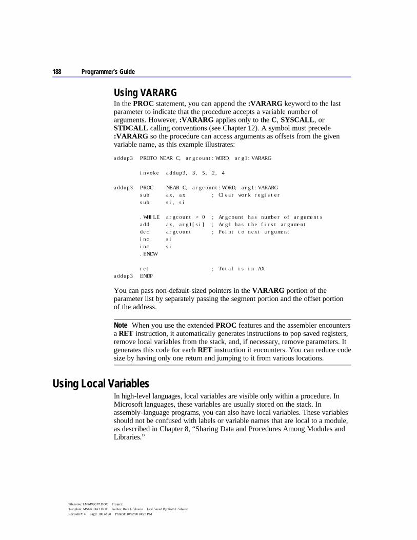
188 Programmer’s Guide
Filename: LMAPGC07.DOC Project: Template: MSGRIDA1.DOT Author: Ruth L Silverio Last Saved By: Ruth L Silverio Revision #: 4 Page: 188 of 28 Printed: 10/02/00 04:23 PM
Using VARARG In the PROC statement, you can append the :VARARG keyword to the last parameter to indicate that the procedure accepts a variable number of arguments. However, :VARARG applies only to the C, SYSCALL, or STDCALL calling conventions (see Chapter 12). A symbol must precede :VARARG so the procedure can access arguments as offsets from the given variable name, as this example illustrates:
addup3 PROTO NEAR C, argcount:WORD, arg1:VARARG invoke addup3, 3, 5, 2, 4 addup3 PROC NEAR C, argcount:WORD, arg1:VARARG sub ax, ax ; Clear work register sub si, si .WHILE argcount > 0 ; Argcount has number of arguments add ax, arg1[si] ; Arg1 has the first argument dec argcount ; Point to next argument inc si inc si .ENDW ret ; Total is in AX addup3 ENDP
You can pass non-default-sized pointers in the VARARG portion of the parameter list by separately passing the segment portion and the offset portion of the address.
When you use the extended PROC features and the assembler encounters a RET instruction, it automatically generates instructions to pop saved registers, remove local variables from the stack, and, if necessary, remove parameters. It generates this code for each RET instruction it encounters. You can reduce code size by having only one return and jumping to it from various locations.
Using Local Variables In high-level languages, local variables are visible only within a procedure. In Microsoft languages, these variables are usually stored on the stack. In assembly-language programs, you can also have local variables. These variables should not be confused with labels or variable names that are local to a module, as described in Chapter 8, “Sharing Data and Procedures Among Modules and Libraries.”
Note
Chapter 7 Controlling Program Flow 189
Filename: LMAPGC07.DOC Project: Template: MSGRIDA1.DOT Author: Ruth L Silverio Last Saved By: Ruth L Silverio Revision #: 4 Page: 189 of 29 Printed: 10/02/00 04:23 PM
This section outlines the standard methods for creating local variables. The next section shows how to use the LOCAL directive to make the assembler
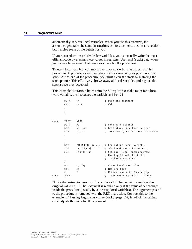
190 Programmer’s Guide
Filename: LMAPGC07.DOC Project: Template: MSGRIDA1.DOT Author: Ruth L Silverio Last Saved By: Ruth L Silverio Revision #: 4 Page: 190 of 30 Printed: 10/02/00 04:23 PM
automatically generate local variables. When you use this directive, the assembler generates the same instructions as those demonstrated in this section but handles some of the details for you.
If your procedure has relatively few variables, you can usually write the most efficient code by placing these values in registers. Use local (stack) data when you have a large amount of temporary data for the procedure.
To use a local variable, you must save stack space for it at the start of the procedure. A procedure can then reference the variable by its position in the stack. At the end of the procedure, you must clean the stack by restoring the stack pointer. This effectively throws away all local variables and regains the stack space they occupied.
This example subtracts 2 bytes from the SP register to make room for a local word variable, then accesses the variable as [bp-2].
push ax ; Push one argument call task ; Call . . . task PROC NEAR push bp ; Save base pointer mov bp, sp ; Load stack into base pointer sub sp, 2 ; Save two bytes for local variable . . . mov WORD PTR [bp-2], 3 ; Initialize local variable add ax, [bp-2] ; Add local variable to AX sub [bp+4], ax ; Subtract local from argument . ; Use [bp-2] and [bp+4] in . ; other operations . mov sp, bp ; Clear local variables pop bp ; Restore base ret 2 ; Return result in AX and pop task ENDP ; two bytes to clear parameter
Notice the instruction mov sp,bp at the end of the procedure restores the original value of SP. The statement is required only if the value of SP changes inside the procedure (usually by allocating local variables). The argument passed to the procedure is removed with the RET instruction. Contrast this to the example in “Passing Arguments on the Stack,” page 182, in which the calling code adjusts the stack for the argument.

Chapter 7 Controlling Program Flow 191
Filename: LMAPGC07.DOC Project: Template: MSGRIDA1.DOT Author: Ruth L Silverio Last Saved By: Ruth L Silverio Revision #: 4 Page: 191 of 31 Printed: 10/02/00 04:23 PM
Figure 7.2 shows the stack at key points in the process.
Figure 7.2 Local Variables on the Stack
Creating Local Variables Automatically MASM’s LOCAL directive automates the process for creating local variables on the stack. LOCAL frees you from having to count stack words, and it makes your code easier to write and maintain. This section illustrates the advantages of creating temporary data with the LOCAL directive.
To use the LOCAL directive, list the variables you want to create, giving a type for each one. The assembler calculates how much space is required on the stack. It also generates instructions to properly decrement SP (as described in the previous section) and to reset SP when you return from the procedure.
When you create local variables this way, your source code can refer to each local variable by name rather than as an offset of the stack pointer. Moreover,
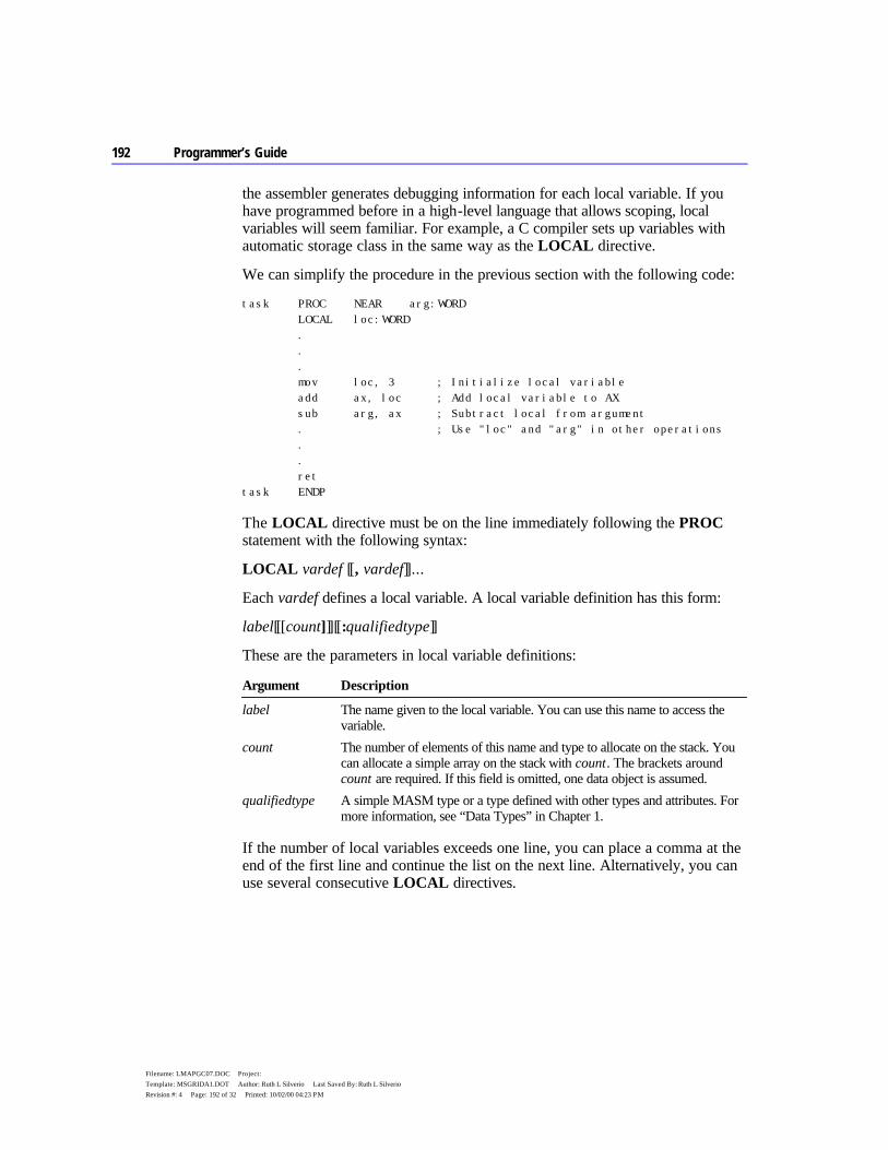
192 Programmer’s Guide
Filename: LMAPGC07.DOC Project: Template: MSGRIDA1.DOT Author: Ruth L Silverio Last Saved By: Ruth L Silverio Revision #: 4 Page: 192 of 32 Printed: 10/02/00 04:23 PM
the assembler generates debugging information for each local variable. If you have programmed before in a high-level language that allows scoping, local variables will seem familiar. For example, a C compiler sets up variables with automatic storage class in the same way as the LOCAL directive.
We can simplify the procedure in the previous section with the following code:
task PROC NEAR arg:WORD LOCAL loc:WORD . . . mov loc, 3 ; Initialize local variable add ax, loc ; Add local variable to AX sub arg, ax ; Subtract local from argument . ; Use "loc" and "arg" in other operations . . ret task ENDP
The LOCAL directive must be on the line immediately following the PROC statement with the following syntax:
LOCAL vardef [[, vardef]]...
Each vardef defines a local variable. A local variable definition has this form:
label[[ [count]]][[:qualifiedtype]]
These are the parameters in local variable definitions:
Argument Description
label The name given to the local variable. You can use this name to access the variable.
count The number of elements of this name and type to allocate on the stack. You can allocate a simple array on the stack with count. The brackets around count are required. If this field is omitted, one data object is assumed.
qualifiedtype A simple MASM type or a type defined with other types and attributes. For more information, see “Data Types” in Chapter 1.
If the number of local variables exceeds one line, you can place a comma at the end of the first line and continue the list on the next line. Alternatively, you can use several consecutive LOCAL directives.
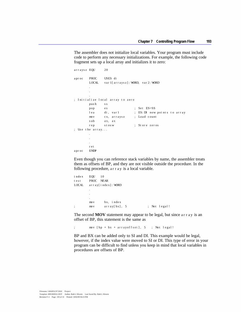
Chapter 7 Controlling Program Flow 193
Filename: LMAPGC07.DOC Project: Template: MSGRIDA1.DOT Author: Ruth L Silverio Last Saved By: Ruth L Silverio Revision #: 4 Page: 193 of 33 Printed: 10/02/00 04:23 PM
The assembler does not initialize local variables. Your program must include code to perform any necessary initializations. For example, the following code fragment sets up a local array and initializes it to zero:
arraysz EQU 20 aproc PROC USES di LOCAL var1[arraysz]:WORD, var2:WORD . . . ; Initialize local array to zero push ss pop es ; Set ES=SS lea di, var1 ; ES:DI now points to array mov cx, arraysz ; Load count sub ax, ax rep stosw ; Store zeros ; Use the array... . . . ret aproc ENDP
Even though you can reference stack variables by name, the assembler treats them as offsets of BP, and they are not visible outside the procedure. In the following procedure, array is a local variable.
index EQU 10 test PROC NEAR LOCAL array[index]:WORD . . . mov bx, index ; mov array[bx], 5 ; Not legal!
The second MOV statement may appear to be legal, but since array is an offset of BP, this statement is the same as
; mov [bp + bx + arrayoffset], 5 ; Not legal!
BP and BX can be added only to SI and DI. This example would be legal, however, if the index value were moved to SI or DI. This type of error in your program can be difficult to find unless you keep in mind that local variables in procedures are offsets of BP.
194 Programmer’s Guide
Filename: LMAPGC07.DOC Project: Template: MSGRIDA1.DOT Author: Ruth L Silverio Last Saved By: Ruth L Silverio Revision #: 4 Page: 194 of 34 Printed: 10/02/00 04:23 PM
Declaring Procedure Prototypes MASM provides the INVOKE directive to handle many of the details important to procedure calls, such as pushing parameters according to the correct calling conventions. To use INVOKE, the procedure called must have been declared previously with a PROC statement, an EXTERNDEF (or EXTERN) statement, or a TYPEDEF. You can also place a prototype defined with PROTO before the INVOKE if the procedure type does not appear before the INVOKE. Procedure prototypes defined with PROTO inform the assembler of types and numbers of arguments so the assembler can check for errors and provide automatic conversions when INVOKE calls the procedure.
Declaring procedure prototypes is good programming practice, but is optional. Prototypes in MASM perform the same function as prototypes in C and other high-level languages. A procedure prototype includes the procedure name, the types, and (optionally) the names of all parameters the procedure expects. Prototypes usually are placed at the beginning of an assembly program or in a separate include file so the assembler encounters the prototype before the actual procedure.
Prototypes enable the assembler to check for unmatched parameters and are especially useful for procedures called from other modules and other languages. If you write routines for a library, you may want to put prototypes into an include file for all the procedures used in that library. For more information about using include files, see Chapter 8, “Sharing Data and Procedures among Modules and Libraries.”
The PROTO directive provides one way to define a procedure prototype. The syntax for a prototype definition is the same as for a procedure declaration (see “Declaring Parameters with the PROC Directive,” earlier in this chapter), except that you do not include the list of registers, prologuearg list, or the scope of the procedure.
Also, the PROTO keyword precedes the langtype and distance attributes. The attributes (like C and FAR) are optional. However, if they are not specified, the defaults are based on any .MODEL or OPTION LANGUAGE statement. The names of the parameters are also optional, but you must list parameter types. A label preceding :VARARG is also optional in the prototype but not in the PROC statement.
If a PROTO and a PROC for the same function appear in the same module, they must match in attribute, number of parameters, and parameter types. The easiest way to create prototypes with PROTO is to write your procedure and then copy the first line (the line that contains the PROC keyword) to a location in your program that follows the data declarations. Change PROC to PROTO and remove the USES reglist, the prologuearg field, and the visibility field. It
Chapter 7 Controlling Program Flow 195
Filename: LMAPGC07.DOC Project: Template: MSGRIDA1.DOT Author: Ruth L Silverio Last Saved By: Ruth L Silverio Revision #: 4 Page: 195 of 35 Printed: 10/02/00 04:23 PM
is important that the prototype follow the declarations for any types used in it to avoid any forward references used by the parameters in the prototype.
The following example illustrates how to define and then declare two typical procedures. In both prototype and declaration, the comma before the argument list is optional only when the list does not appear on a separate line:
; Procedure prototypes. addup PROTO NEAR C argcount:WORD, arg2:WORD, arg3:WORD myproc PROTO FAR C, argcount:WORD, arg2:VARARG ; Procedure declarations addup PROC NEAR C, argcount:WORD, arg2:WORD, arg3:WORD . . . myproc PROC FAR C PUBLIC <callcount> USES di si, argcount:WORD, arg2:VARARG
When you call a procedure with INVOKE, the assembler checks the arguments given by INVOKE against the parameters expected by the procedure. If the data types of the arguments do not match, MASM reports an error or converts the type to the expected type. These conversions are explained in the next section.
Calling Procedures with INVOKE INVOKE generates a sequence of instructions that push arguments and call a procedure. This helps maintain code if arguments or langtype for a procedure are changed. INVOKE generates procedure calls and automatically:
u Converts arguments to the expected types. u Pushes arguments on the stack in the correct order. u Cleans the stack when the procedure returns.
If arguments do not match in number or if the type is not one the assembler can convert, an error results.
If the procedure uses VARARG, INVOKE can pass a number of arguments different from the number in the parameter list without generating an error or warning. Any additional arguments must be at the end of the INVOKE argument list. All other arguments must match those in the prototype parameter list.
196 Programmer’s Guide
Filename: LMAPGC07.DOC Project: Template: MSGRIDA1.DOT Author: Ruth L Silverio Last Saved By: Ruth L Silverio Revision #: 4 Page: 196 of 36 Printed: 10/02/00 04:23 PM
The syntax for INVOKE is:
INVOKE expression [[, arguments]]
where expression can be the procedure’s label or an indirect reference to a procedure, and arguments can be an expression, a register pair, or an expression preceded with ADDR. (The ADDR operator is discussed later in this chapter.)
Procedures with these prototypes
addup PROTO NEAR C argcount:WORD, arg2:WORD, arg3:WORD myproc PROTO FAR C, argcount:WORD, arg2:VARARG
and these procedure declarations
addup PROC NEAR C, argcount:WORD, arg2:WORD, arg3:WORD . . . myproc PROC FAR C PUBLIC <callcount> USES di si, argcount:WORD, arg2:VARARG
can be called with INVOKE statements like this:
INVOKE addup, ax, x, y INVOKE myproc, bx, cx, 100, 10
The assembler can convert some arguments and parameter type combinations so that the correct type can be passed. The signed or unsigned qualities of the arguments in the INVOKE statements determine how the assembler converts them to the types expected by the procedure.
The addup procedure, for example, expects parameters of type WORD, but the arguments passed by INVOKE to the addup procedure can be any of these types:
uu BYTE, SBYTE, WORD, or SWORD u An expression whose type is specified with the PTR operator to be one of
those types u An 8-bit or 16-bit register u An immediate expression in the range –32K to +64K u A NEAR PTR
If the type is smaller than that expected by the procedure, MASM widens the argument to match.

Chapter 7 Controlling Program Flow 197
Filename: LMAPGC07.DOC Project: Template: MSGRIDA1.DOT Author: Ruth L Silverio Last Saved By: Ruth L Silverio Revision #: 4 Page: 197 of 37 Printed: 10/02/00 04:23 PM
Widening Arguments For INVOKE to correctly handle type conversions, you must use the signed data types for any signed assignments. MASM widens an argument to match the type expected by a procedure’s parameters in these cases:
Type Passed Type Expected
BYTE, SBYTE WORD, SWORD, DWORD, SDWORD WORD, SWORD DWORD, SDWORD
The assembler can extend a segment if far data is expected, and it can convert the type given in the list to the types expected. If the assembler cannot convert the type, however, it generates an error.
Detecting Errors If the assembler needs to widen an argument, it first copies the value to AL or AX. It widens an unsigned value by placing a zero in the higher register area, and widens a signed value with a CBW, CWD, or CWDE instruction as required. Similarly, the assembler copies a constant argument value into AL or AX when the .8086 directive is in effect. You can see these generated instructions in the listing file when you include the /Sg command-line option.
Using the accumulator register to widen or copy an argument may lead to an error if you attempt to pass AX as another argument. For example, consider the following INVOKE statement for a procedure with the C calling convention
INVOKE myprocA, ax, cx, 100, arg
where arg is a BYTE variable and myproc expects four arguments of type WORD. The assembler widens and then pushes arg like this:
mov al, DGROUP:arg xor ah, ah push ax
The generated code thus overwrites the last argument (AX) passed to the procedure. The assembler generates an error in this case, requiring you to rewrite the INVOKE statement.
To summarize, the INVOKE directive overwrites AX and perhaps DX when widening arguments. It also uses AX to push constants on the 8088 and 8086. If you use these registers (or EAX and EDX on an 80386/486) to pass arguments, they may be overwritten. The assembler’s error detection prevents this from ever becoming a run-time bug, but AX and DX should remain your last choice for holding arguments.
198 Programmer’s Guide
Filename: LMAPGC07.DOC Project: Template: MSGRIDA1.DOT Author: Ruth L Silverio Last Saved By: Ruth L Silverio Revision #: 4 Page: 198 of 38 Printed: 10/02/00 04:23 PM
Invoking Far Addresses You can pass a FAR pointer in a segment::offset pair, as shown in the following. Note the use of double colons to separate the register pair. The registers could be any other register pair, including a pair that an MS-DOS call uses to return values.
FPWORD TYPEDEF FAR PTR WORD SomeProc PROTO var1:DWORD, var2:WORD, var3:WORD pfaritem FPWORD faritem . . . les bx, pfaritem INVOKE SomeProc, ES::BX, arg1, arg2
However, INVOKE cannot combine into a single address one argument for the segment and one for the offset.
Passing an Address You can use the ADDR operator to pass the address of an expression to a procedure that expects a NEAR or FAR pointer. This example generates code to pass a far pointer (to arg1) to the procedure proc1.
PBYTE TYPEDEF FAR PTR BYTE arg1 BYTE "This is a string" proc1 PROTO NEAR C fparg:PBYTE . . . INVOKE proc1, ADDR arg1
For information on defining pointers with TYPEDEF, see “Defining Pointer Types with TYPEDEF” in Chapter 3.
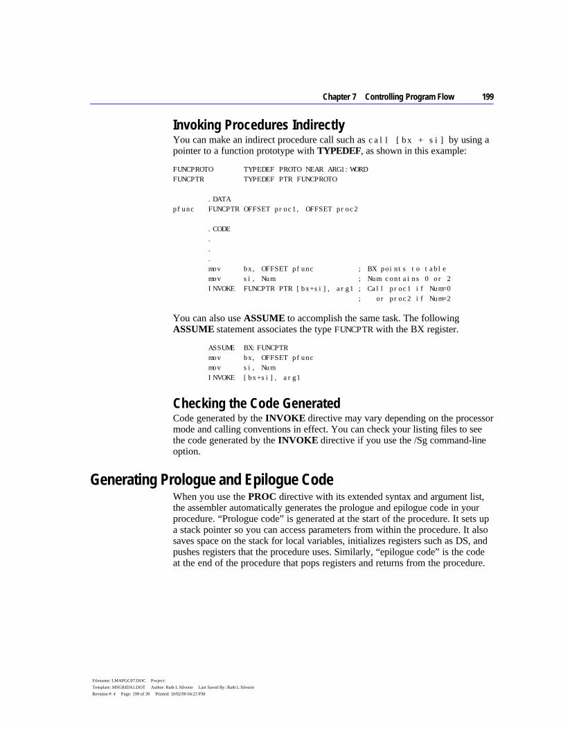
Chapter 7 Controlling Program Flow 199
Filename: LMAPGC07.DOC Project: Template: MSGRIDA1.DOT Author: Ruth L Silverio Last Saved By: Ruth L Silverio Revision #: 4 Page: 199 of 39 Printed: 10/02/00 04:23 PM
Invoking Procedures Indirectly You can make an indirect procedure call such as call [bx + si] by using a pointer to a function prototype with TYPEDEF, as shown in this example:
FUNCPROTO TYPEDEF PROTO NEAR ARG1:WORD FUNCPTR TYPEDEF PTR FUNCPROTO .DATA pfunc FUNCPTR OFFSET proc1, OFFSET proc2 .CODE . . . mov bx, OFFSET pfunc ; BX points to table mov si, Num ; Num contains 0 or 2 INVOKE FUNCPTR PTR [bx+si], arg1 ; Call proc1 if Num=0 ; or proc2 if Num=2
You can also use ASSUME to accomplish the same task. The following ASSUME statement associates the type FUNCPTR with the BX register.
ASSUME BX:FUNCPTR mov bx, OFFSET pfunc mov si, Num INVOKE [bx+si], arg1
Checking the Code Generated Code generated by the INVOKE directive may vary depending on the processor mode and calling conventions in effect. You can check your listing files to see the code generated by the INVOKE directive if you use the /Sg command-line option.
Generating Prologue and Epilogue Code When you use the PROC directive with its extended syntax and argument list, the assembler automatically generates the prologue and epilogue code in your procedure. “Prologue code” is generated at the start of the procedure. It sets up a stack pointer so you can access parameters from within the procedure. It also saves space on the stack for local variables, initializes registers such as DS, and pushes registers that the procedure uses. Similarly, “epilogue code” is the code at the end of the procedure that pops registers and returns from the procedure.
200 Programmer’s Guide
Filename: LMAPGC07.DOC Project: Template: MSGRIDA1.DOT Author: Ruth L Silverio Last Saved By: Ruth L Silverio Revision #: 4 Page: 200 of 40 Printed: 10/02/00 04:23 PM
The assembler automatically generates the prologue code when it encounters the first instruction or label after the PROC directive. This means you cannot label the prologue for the purpose of jumping to it. The assembler generates the epilogue code when it encounters a RET or IRET instruction. Using the assembler-generated prologue and epilogue code saves time and decreases the number of repetitive lines of code in your procedures.
The generated prologue or epilogue code depends on the:
u Local variables defined. u Arguments passed to the procedure. u Current processor selected (affects epilogue code only). u Current calling convention. u Options passed in the prologuearg of the PROC directive. u Registers being saved.
The prologuearg list contains options specifying how to generate the prologue or epilogue code. The next section explains how to use these options, gives the standard prologue and epilogue code, and explains the techniques for defining your own prologue and epilogue code.
Using Automatic Prologue and Epilogue Code The standard prologue and epilogue code handles parameters and local variables. If a procedure does not have any parameters or local variables, the prologue and epilogue code that sets up and restores a stack pointer is omitted, unless FORCEFRAME is included in the prologuearg list. (FORCEFRAME is discussed later in this section.) Prologue and epilogue code also generates a push and pop for each register in the register list.
The prologue code consists of three steps:
1. Point BP to top of stack. 2. Make space on stack for local variables. 3. Save registers the procedure must preserve.
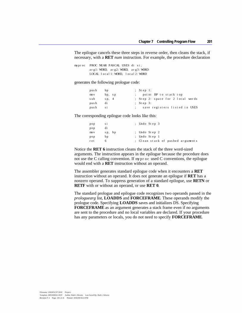
Chapter 7 Controlling Program Flow 201
Filename: LMAPGC07.DOC Project: Template: MSGRIDA1.DOT Author: Ruth L Silverio Last Saved By: Ruth L Silverio Revision #: 4 Page: 201 of 41 Printed: 10/02/00 04:23 PM
The epilogue cancels these three steps in reverse order, then cleans the stack, if necessary, with a RET num instruction. For example, the procedure declaration
myproc PROC NEAR PASCAL USES di si, arg1:WORD, arg2:WORD, arg3:WORD LOCAL local1:WORD, local2:WORD
generates the following prologue code:
push bp ; Step 1: mov bp, sp ; point BP to stack top sub sp, 4 ; Step 2: space for 2 local words push di ; Step 3: push si ; save registers listed in USES
The corresponding epilogue code looks like this:
pop si ; Undo Step 3 pop di mov sp, bp ; Undo Step 2 pop bp ; Undo Step 1 ret 6 ; Clean stack of pushed arguments
Notice the RET 6 instruction cleans the stack of the three word-sized arguments. The instruction appears in the epilogue because the procedure does not use the C calling convention. If myproc used C conventions, the epilogue would end with a RET instruction without an operand.
The assembler generates standard epilogue code when it encounters a RET instruction without an operand. It does not generate an epilogue if RET has a nonzero operand. To suppress generation of a standard epilogue, use RETN or RETF with or without an operand, or use RET 0.
The standard prologue and epilogue code recognizes two operands passed in the prologuearg list, LOADDS and FORCEFRAME. These operands modify the prologue code. Specifying LOADDS saves and initializes DS. Specifying FORCEFRAME as an argument generates a stack frame even if no arguments are sent to the procedure and no local variables are declared. If your procedure has any parameters or locals, you do not need to specify FORCEFRAME.
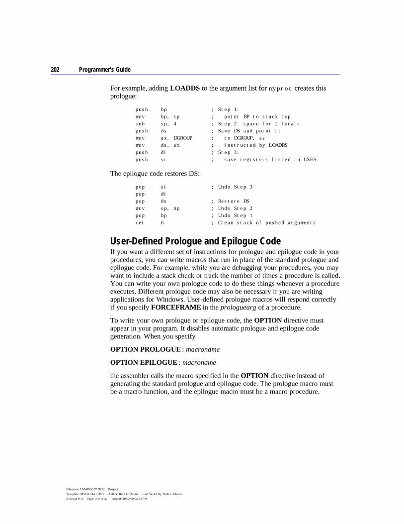
202 Programmer’s Guide
Filename: LMAPGC07.DOC Project: Template: MSGRIDA1.DOT Author: Ruth L Silverio Last Saved By: Ruth L Silverio Revision #: 4 Page: 202 of 42 Printed: 10/02/00 04:23 PM
For example, adding LOADDS to the argument list for myproc creates this prologue:
push bp ; Step 1: mov bp, sp ; point BP to stack top sub sp, 4 ; Step 2: space for 2 locals push ds ; Save DS and point it mov ax, DGROUP ; to DGROUP, as mov ds, ax ; instructed by LOADDS push di ; Step 3: push si ; save registers listed in USES
The epilogue code restores DS:
pop si ; Undo Step 3 pop di pop ds ; Restore DS mov sp, bp ; Undo Step 2 pop bp ; Undo Step 1 ret 6 ; Clean stack of pushed arguments
User-Defined Prologue and Epilogue Code If you want a different set of instructions for prologue and epilogue code in your procedures, you can write macros that run in place of the standard prologue and epilogue code. For example, while you are debugging your procedures, you may want to include a stack check or track the number of times a procedure is called. You can write your own prologue code to do these things whenever a procedure executes. Different prologue code may also be necessary if you are writing applications for Windows. User-defined prologue macros will respond correctly if you specify FORCEFRAME in the prologuearg of a procedure.
To write your own prologue or epilogue code, the OPTION directive must appear in your program. It disables automatic prologue and epilogue code generation. When you specify
OPTION PROLOGUE : macroname
OPTION EPILOGUE : macroname
the assembler calls the macro specified in the OPTION directive instead of generating the standard prologue and epilogue code. The prologue macro must be a macro function, and the epilogue macro must be a macro procedure.
Chapter 7 Controlling Program Flow 203
Filename: LMAPGC07.DOC Project: Template: MSGRIDA1.DOT Author: Ruth L Silverio Last Saved By: Ruth L Silverio Revision #: 4 Page: 203 of 43 Printed: 10/02/00 04:23 PM
The assembler expects your prologue or epilogue macro to have this form:
macroname MACRO procname, \ flag, \ parmbytes, \ localbytes, \ <reglist>, \ userparms
Your macro must have formal parameters to match all the actual arguments passed. The arguments passed to your macro include:
Argument Description
procname The name of the procedure. flag A 16-bit flag containing the following information: Bit = Value Description
Bit 0, 1, 2 For calling conventions (000=unspecified language type, 001=C, 010=SYSCALL, 011=STDCALL, 100=PASCAL, 101=FORTRAN, 110=BASIC).
Bit 3 Undefined (not necessarily zero). Bit 4 Set if the caller restores the stack
(use RET, not RETn). Bit 5 Set if procedure is FAR. Bit 6 Set if procedure is PRIVATE. Bit 7 Set if procedure is EXPORT. Bit 8 Set if the epilogue is generated as a result of an IRET
instruction and cleared if the epilogue is generated as a result of a RET instruction.
Bits 9–15 Undefined (not necessarily zero). parmbytes The accumulated count in bytes of all parameters given in the PROC
statement. localbytes The count in bytes of all locals defined with the LOCAL directive. reglist A list of the registers following the USES operator in the procedure
declaration. Enclose this list with angle brackets (< >) and separate each item with commas. Reverse the list for epilogues.
userparms Any argument you want to pass to the macro. The prologuearg (if there is one) specified in the PROC directive is passed to this argument.
Your macro function must return the parmbytes parameter. However, if the prologue places other values on the stack after pushing BP and these values are not referenced by any of the local variables, the exit value must be the number of bytes for procedure locals plus any space between BP and the locals. Therefore, parmbytes is not always equal to the bytes occupied by the locals.
204 Programmer’s Guide
Filename: LMAPGC07.DOC Project: Template: MSGRIDA1.DOT Author: Ruth L Silverio Last Saved By: Ruth L Silverio Revision #: 4 Page: 204 of 44 Printed: 10/02/00 04:23 PM
The following macro is an example of a user-defined prologue that counts the number of times a procedure is called.
ProfilePro MACRO procname, \ flag, \ bytecount, \ numlocals, \ regs, \ macroargs .DATA procname&count WORD 0 .CODE inc procname&count ; Accumulates count of times the ; procedure is called push bp mov bp, sp ; Other BP operations IFNB <regs> FOR r, regs push r ENDM ENDIF EXITM %bytecount ENDM
Your program must also include this statement before calling any procedures that use the prologue:
OPTION PROLOGUE:ProfilePro
If you define either a prologue or an epilogue macro, the assembler uses the standard prologue or epilogue code for the one you do not define. The form of the code generated depends on the .MODEL and PROC options used.
If you want to revert to the standard prologue or epilogue code, use PROLOGUEDEF or EPILOGUEDEF as the macroname in the OPTION statement.
OPTION EPILOGUE:EPILOGUEDEF
You can completely suppress prologue or epilogue generation with
OPTION PROLOGUE:None OPTION EPILOGUE:None
In this case, no user-defined macro is called, and the assembler does not generate a default code sequence. This state remains in effect until the next OPTION PROLOGUE or OPTION EPILOGUE is encountered.
Chapter 7 Controlling Program Flow 205
Filename: LMAPGC07.DOC Project: Template: MSGRIDA1.DOT Author: Ruth L Silverio Last Saved By: Ruth L Silverio Revision #: 4 Page: 205 of 45 Printed: 10/02/00 04:23 PM
For additional information about writing macros, see Chapter 9, “Using Macros.” The PROLOGUE.INC file provided in the MASM 6.1 distribution disks can create the prologue and epilogue sequences for the Microsoft C professional development system.
MS-DOS Interrupts In addition to jumps, loops, and procedures that alter program execution, interrupt routines transfer execution to a different location. In this case, control goes to an interrupt routine.
You can write your own interrupt routines, either to replace an existing routine or to use an undefined interrupt number. For example, you may want to replace an MS-DOS interrupt handler, such as the Critical Error (Interrup 24h) and CONTROL+C (Interrupt 23h) handlers. The BOUND instruction checks array bounds and calls Interrupt 5 when an error occurs. If you use this instruction, you need to write an interrupt handler for it.
This section summarizes the following:
u How to call interrupts u How the processor handles interrupts u How to redefine an existing interrupt routine
The example routine in this section handles addition or multiplication overflow and illustrates the steps necessary for writing an interrupt routine. For additional information about MS-DOS and BIOS interrupts, see Chapter 11, “Writing Memory-Resident Software.”
Calling MS-DOS and ROM-BIOS Interrupts Interrupts provide a way to access MS-DOS and ROM-BIOS from assembly language. They are called with the INT instruction, which takes an immediate value between 0 and 255 as its only operand.
MS-DOS and ROM-BIOS interrupt routines accept data through registers. For instance, most MS-DOS routines (and many BIOS routines) require a function number in the AH register. Many handler routines also return values in registers. To use an interrupt, you must know what data the handler routine expects and what data, if any, it returns. For information, consult Help or one of the other references mentioned in the Introduction.
206 Programmer’s Guide
Filename: LMAPGC07.DOC Project: Template: MSGRIDA1.DOT Author: Ruth L Silverio Last Saved By: Ruth L Silverio Revision #: 4 Page: 206 of 46 Printed: 10/02/00 04:23 PM
The following fragment illustrates a simple call to MS-DOS Function 9, which displays the string msg on the screen:
.DATA msg BYTE "This writes to the screen$" .CODE mov ax, SEG msg ; Necessary only if DS does not mov ds, ax ; already point to data segment mov dx, offset msg ; DS:DX points to msg mov ah, 09h ; Request Function 9 int 21h
When the INT instruction executes, the processor:
1. Looks up the address of the interrupt routine in the Interrupt Vector Table. This table starts at the lowest point in memory (segment 0, offset 0) and consists of a series of far pointers called vectors. Each vector comprises a 4-byte address (segment:offset) pointing to an interrupt handler routine. The table sequence implies the number of the interrupt the vector references: the first vector points to the Interrupt 0 handler, the second vector to the Interrupt 1 handler, and so forth. Thus, the vector at 0000:i*4 holds the address of the handler routine for Interrupt i.
2. Clears the trap flag (TF) and interrupt enable flag (IF). 3. Pushes the flags register, the current code segment (CS), and the current
instruction pointer (IP), in that order. (The current instruction is the one following the INT statement.) As with a CALL, this ensures control returns to the next logical position in the program.
4. Jumps to the address of the interrupt routine, as specified in the Interrupt Vector Table.
5. Executes the code of the interrupt routine until it encounters an IRET instruction.
6. Pops the instruction pointer, code segment, and flags.
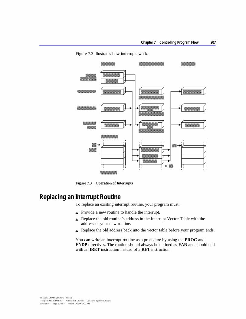
Chapter 7 Controlling Program Flow 207
Filename: LMAPGC07.DOC Project: Template: MSGRIDA1.DOT Author: Ruth L Silverio Last Saved By: Ruth L Silverio Revision #: 4 Page: 207 of 47 Printed: 10/02/00 04:23 PM
Figure 7.3 illustrates how interrupts work.
Figure 7.3 Operation of Interrupts
Replacing an Interrupt Routine To replace an existing interrupt routine, your program must:
u Provide a new routine to handle the interrupt. u Replace the old routine’s address in the Interrupt Vector Table with the
address of your new routine. u Replace the old address back into the vector table before your program ends.
You can write an interrupt routine as a procedure by using the PROC and ENDP directives. The routine should always be defined as FAR and should end with an IRET instruction instead of a RET instruction.
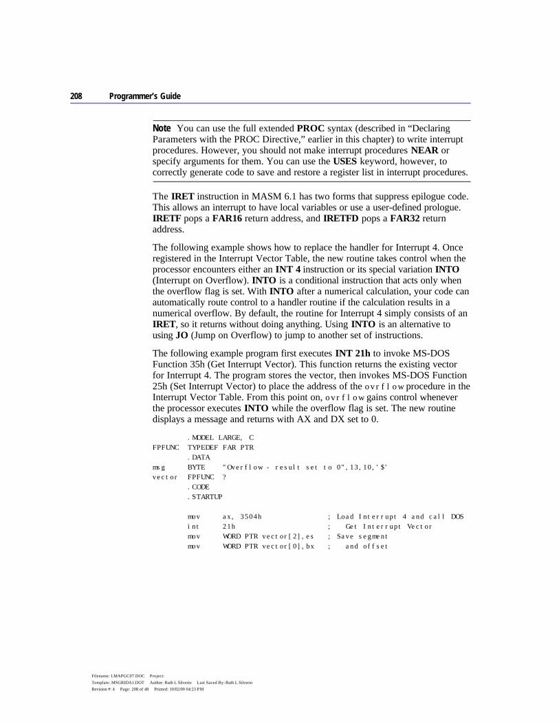
208 Programmer’s Guide
Filename: LMAPGC07.DOC Project: Template: MSGRIDA1.DOT Author: Ruth L Silverio Last Saved By: Ruth L Silverio Revision #: 4 Page: 208 of 48 Printed: 10/02/00 04:23 PM
You can use the full extended PROC syntax (described in “Declaring Parameters with the PROC Directive,” earlier in this chapter) to write interrupt procedures. However, you should not make interrupt procedures NEAR or specify arguments for them. You can use the USES keyword, however, to correctly generate code to save and restore a register list in interrupt procedures.
The IRET instruction in MASM 6.1 has two forms that suppress epilogue code. This allows an interrupt to have local variables or use a user-defined prologue. IRETF pops a FAR16 return address, and IRETFD pops a FAR32 return address.
The following example shows how to replace the handler for Interrupt 4. Once registered in the Interrupt Vector Table, the new routine takes control when the processor encounters either an INT 4 instruction or its special variation INTO (Interrupt on Overflow). INTO is a conditional instruction that acts only when the overflow flag is set. With INTO after a numerical calculation, your code can automatically route control to a handler routine if the calculation results in a numerical overflow. By default, the routine for Interrupt 4 simply consists of an IRET, so it returns without doing anything. Using INTO is an alternative to using JO (Jump on Overflow) to jump to another set of instructions.
The following example program first executes INT 21h to invoke MS-DOS Function 35h (Get Interrupt Vector). This function returns the existing vector for Interrupt 4. The program stores the vector, then invokes MS-DOS Function 25h (Set Interrupt Vector) to place the address of the ovrflow procedure in the Interrupt Vector Table. From this point on, ovrflow gains control whenever the processor executes INTO while the overflow flag is set. The new routine displays a message and returns with AX and DX set to 0.
.MODEL LARGE, C FPFUNC TYPEDEF FAR PTR .DATA msg BYTE "Overflow - result set to 0",13,10,'$' vector FPFUNC ? .CODE .STARTUP mov ax, 3504h ; Load Interrupt 4 and call DOS int 21h ; Get Interrupt Vector mov WORD PTR vector[2],es ; Save segment mov WORD PTR vector[0],bx ; and offset
Note
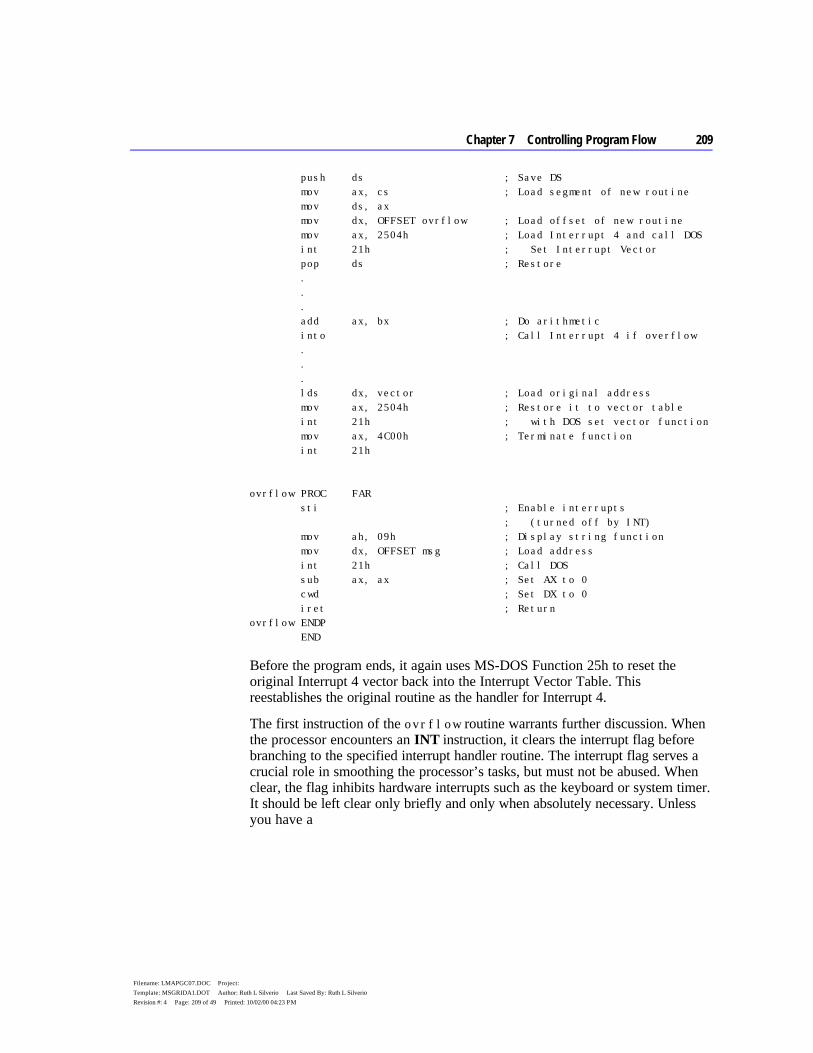
Chapter 7 Controlling Program Flow 209
Filename: LMAPGC07.DOC Project: Template: MSGRIDA1.DOT Author: Ruth L Silverio Last Saved By: Ruth L Silverio Revision #: 4 Page: 209 of 49 Printed: 10/02/00 04:23 PM
push ds ; Save DS mov ax, cs ; Load segment of new routine mov ds, ax mov dx, OFFSET ovrflow ; Load offset of new routine mov ax, 2504h ; Load Interrupt 4 and call DOS int 21h ; Set Interrupt Vector pop ds ; Restore . . . add ax, bx ; Do arithmetic into ; Call Interrupt 4 if overflow . . . lds dx, vector ; Load original address mov ax, 2504h ; Restore it to vector table int 21h ; with DOS set vector function mov ax, 4C00h ; Terminate function int 21h ovrflow PROC FAR sti ; Enable interrupts ; (turned off by INT) mov ah, 09h ; Display string function mov dx, OFFSET msg ; Load address int 21h ; Call DOS sub ax, ax ; Set AX to 0 cwd ; Set DX to 0 iret ; Return ovrflow ENDP END
Before the program ends, it again uses MS-DOS Function 25h to reset the original Interrupt 4 vector back into the Interrupt Vector Table. This reestablishes the original routine as the handler for Interrupt 4.
The first instruction of the ovrflow routine warrants further discussion. When the processor encounters an INT instruction, it clears the interrupt flag before branching to the specified interrupt handler routine. The interrupt flag serves a crucial role in smoothing the processor’s tasks, but must not be abused. When clear, the flag inhibits hardware interrupts such as the keyboard or system timer. It should be left clear only briefly and only when absolutely necessary. Unless you have a
210 Programmer’s Guide
Filename: LMAPGC07.DOC Project: Template: MSGRIDA1.DOT Author: Ruth L Silverio Last Saved By: Ruth L Silverio Revision #: 4 Page: 210 of 50 Printed: 10/02/00 04:23 PM
compelling reason to leave the flag clear, always include an STI (Set Interrupt Flag) instruction at the beginning of your interrupt handler routine to reenable hardware interrupts.
CLI (Clear Interrupt Flag) and its corollary STI are designed to protect small sections of time-dependent code from interruptions by the hardware. If you use CLI in your program, be sure to include a matching STI instruction as well. The sample interrupt handlers in Chapter 11, “Writing Memory-Resident Software,” illustrate how to use these important instructions.


210 Programmer’s Guide
Filename: LMAPGC07.DOC Project: Template: MSGRIDA1.DOT Author: Ruth L Silverio Last Saved By: Ruth L Silverio Revision #: 4 Page: 210 of 52 Printed: 10/02/00 04:23 PM
211
Filename: LMAPGC08.DOC Project: Template: MSGRIDA1.DOT Author: Ruth L Silverio Last Saved By: Ruth L Silverio Revision #: 4 Page: 211 of 1 Printed: 10/02/00 04:22 PM
C H A P T E R 8
To use symbols and procedures in more than one module, the assembler must be able to recognize the shared data as global to all the modules where they are used. MASM provides techniques to simplify data-sharing and give a high-level interface to multiple-module programming. With these techniques, you can place shared symbols in include files. This makes the data declarations in the file available to all modules that use the include file.
This chapter explains the two data-sharing methods MASM 6.1 offers. The first method simplifies data sharing between modules with include files. The second does not involve include files. Instead, this method allows modules to share procedures and data items using the PUBLIC and EXTERN directives.
The last section of this chapter explains how to create program libraries and access their routines.
Selecting Data-Sharing Methods If data defined in one module is to be used in other modules of a program, you must declare the data public and external. MASM provides several ways to do this:
u Declare a symbol public with the PUBLIC directive in the module where it is defined. This makes the symbol available to other modules. You must also place an EXTERN statement for that symbol in all other modules that refer to the public symbol. This statement informs the assembler that the symbol is external — that is, defined in another module.
u Declare the data communal with the COMM directive. However, communal variables have limitations. You cannot depend on their location in memory because they are allocated by the linker, and they cannot be initialized.
The EXTERNDEF directive declares a symbol either public or external, as appropriate. EXTERNDEF simplifies the declarations for global (public and external) variables and encourages the use of include files.
Sharing Data and Procedures Among Modules and Libraries
212 Programmer’s Guide
Filename: LMAPGC08.DOC Project: Template: MSGRIDA1.DOT Author: Ruth L Silverio Last Saved By: Ruth L Silverio Revision #: 4 Page: 212 of 2 Printed: 10/02/00 04:22 PM
The next section provides further details on using include files. For more information on PUBLIC and EXTERN, see “Using Alternatives to Include Files,” page 219.
Sharing Symbols with Include Files Include files can contain any valid MASM statement, but typically consist of type and symbol declarations. The assembler inserts the contents of the include file into a module at the location of the INCLUDE directive. Include files are optional, but can simplify project organization by eliminating the need to insert common declarations into all modules of a program. An alternative to using include files is described in “Using Alternatives to Include Files,” page 219.
This section explains how to organize symbol definitions and the declarations that make them global (available to all modules); how to make both variables and procedures public with EXTERNDEF, PROTO, and COMM.; and where to place these directives in the modules and include files.
Organizing Modules This section summarizes the organization of declarations and definitions in modules and include files and the use of the INCLUDE directive.
Include Files Type declarations that need to be identical in every module should be placed in an include file. This ensures consistency and saves time when you update programs. Include files should contain only symbol declarations and any other declarations that are resolved at assembly time. (For a list of assembly-time operations, see “Generating and Running Executable Programs” in Chapter 1.)
If more than one module accesses the include file, the file cannot contain statements that define and allocate memory for symbols. Otherwise, the assembler would attempt to allocate the same symbol more than once.
An include file used in two or more modules should not allocate data variables.
Modules An INCLUDE statement is usually placed before data and code segments in your modules. When the assembler encounters an INCLUDE directive, it opens the specified file and assembles all its statements. The assembler then returns to the original module and continues the assembly.
Note
Chapter 8 Sharing Data and Procedures Among Modules and Libraries 213
Filename: LMAPGC08.DOC Project: Template: MSGRIDA1.DOT Author: Ruth L Silverio Last Saved By: Ruth L Silverio Revision #: 4 Page: 213 of 3 Printed: 10/02/00 04:22 PM
The INCLUDE directive takes the form:
INCLUDE filename
where filename is the full name of the include file. For example, the following declaration inserts the contents of the include file SCREEN.INC in your program:
INCLUDE SCREEN.INC
The filename in the INCLUDE directive must be fully specified; no extensions are assumed. If a full pathname is not given, the assembler first searches the directory of the source file containing the INCLUDE directive.
If the include file is not in the source file directory, the assembler searches the paths specified in the assembler’s command-line option /I, or in PWB’s Include Paths field in the MASM Option dialog box (accessed from the Option menu). The /I option takes this form:
/I path
You can include more than one /I option on the command line. The assembler then searches for include files within each specified path in the order given. If none of these directories contains the include file, the assembler finally searches in the paths specified in the INCLUDE environment variable. If the include file still cannot be found, an assembly error occurs. (The /x command-line option tells the assembler to ignore the INCLUDE environment variable when searching for include files.)
An include file may specify another include file. The assembler processes the second include file before returning to the first. Your program can nest include files this way as deeply as the amount of free memory allows.
Include Files or Modules You can use the EQU directive to create named constants that cannot be redefined in your program. (For information about the EQU directive, see “Integer Constants and Constant Expressions,” page 11.) Placing a constant defined with EQU in an include file makes it available to all modules that use that include file.
Placing TYPEDEF, STRUCT, UNION, and RECORD definitions in an include file guarantees consistency in type definitions. If required, the variable instances derived from these definitions can be made public among the modules with EXTERNDEF declarations (see the next section). Macros, including macros defined with TEXTEQU, must be placed in include files to make them visible in other modules.
214 Programmer’s Guide
Filename: LMAPGC08.DOC Project: Template: MSGRIDA1.DOT Author: Ruth L Silverio Last Saved By: Ruth L Silverio Revision #: 4 Page: 214 of 4 Printed: 10/02/00 04:22 PM
If you elect to use full segment definitions with, or instead of, simplified definitions, you can force a consistent segment order in all files by defining segments in an include file. This technique is explained in “Controlling the Segment Order,” page 47.
Declaring Symbols Public and External It is sometimes useful to make certain procedures and variables (such as status flags) global to all program modules. Global variables are freely accessible within all routines; you do not have to explicitly pass them to the routines that need them. This section describes how to make variables and procedures global using the EXTERNDEF, PROTO, or COMM declarations within include files.
When a procedure is defined in one module and called in another module, it must be declared public in the defining module and external in the calling module(s). MASM offers three ways to declare a procedure public and external:
u Use the PUBLIC directive in the defining module and EXTERN in all other modules that reference the procedure. The PUBLIC and EXTERN directives are explained on page 220.
u Declare the procedure with EXTERNDEF. u Prototype the procedure with the PROTO directive.
Using EXTERNDEF MASM treats EXTERNDEF as a public declaration in the defining module, and as an external declaration in the referencing module(s). You can use the EXTERNDEF statement in your include file to make a variable common to two or more modules. EXTERNDEF works with all types of variables, including arrays, structures, unions, and records. It also works with procedures.
As a result, a single include file can contain an EXTERNDEF declaration that works in both the defining module and any referencing module. It is ignored in modules that neither define nor reference the variable. Therefore, an include file for a library which is used in multiple .EXE files does not force the definition of a symbol as EXTERN does.
The EXTERNDEF statement takes this form:
EXTERNDEF [[langtype]] name:qualifiedtype
The name is the variable’s identifier. The qualifiedtype is explained in detail in “Data Types,” page 14.
The optional langtype specifier sets the naming conventions for the name it precedes. It overrides any language specified in the .MODEL directive. The specifier can be C, SYSCALL, STDCALL, PASCAL, FORTRAN, or
Chapter 8 Sharing Data and Procedures Among Modules and Libraries 215
Filename: LMAPGC08.DOC Project: Template: MSGRIDA1.DOT Author: Ruth L Silverio Last Saved By: Ruth L Silverio Revision #: 4 Page: 215 of 5 Printed: 10/02/00 04:22 PM
BASIC. For information on selecting the appropriate langtype type, see “Naming and Calling Conventions,” page 308.
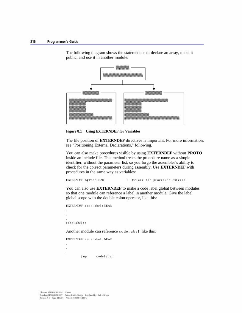
216 Programmer’s Guide
Filename: LMAPGC08.DOC Project: Template: MSGRIDA1.DOT Author: Ruth L Silverio Last Saved By: Ruth L Silverio Revision #: 4 Page: 216 of 6 Printed: 10/02/00 04:22 PM
The following diagram shows the statements that declare an array, make it public, and use it in another module.
Figure 8.1 Using EXTERNDEF for Variables
The file position of EXTERNDEF directives is important. For more information, see “Positioning External Declarations,” following.
You can also make procedures visible by using EXTERNDEF without PROTO inside an include file. This method treats the procedure name as a simple identifier, without the parameter list, so you forgo the assembler’s ability to check for the correct parameters during assembly. Use EXTERNDEF with procedures in the same way as variables:
EXTERNDEF MyProc:FAR ; Declare far procedure external
You can also use EXTERNDEF to make a code label global between modules so that one module can reference a label in another module. Give the label global scope with the double colon operator, like this:
EXTERNDEF codelabel:NEAR . . . codelabel::
Another module can reference codelabel like this:
EXTERNDEF codelabel:NEAR . . . jmp codelabel

Chapter 8 Sharing Data and Procedures Among Modules and Libraries 217
Filename: LMAPGC08.DOC Project: Template: MSGRIDA1.DOT Author: Ruth L Silverio Last Saved By: Ruth L Silverio Revision #: 4 Page: 217 of 7 Printed: 10/02/00 04:22 PM
Using PROTO This section describes how to prototype a procedure with the PROTO directive. PROTO automatically issues an EXTERNDEF for the procedure unless the PROC statement declares the procedure PRIVATE. Defining a prototype enables type-checking for the procedure arguments.
Follow these steps to create an interface for a procedure defined in one module and called from other modules:
1. Place the PROTO declaration in the include file. 2. Define the procedure with PROC in one module. The PROC directive
declares the procedure PUBLIC by default. 3. Call the procedure with the INVOKE statement (or with CALL). Make sure
that all calling modules access the include file.
For descriptions, syntax, and examples of PROTO, PROC, and INVOKE, see Chapter 7, “Controlling Program Flow.”
The following example illustrates these three steps. In the example, a PROTO statement defines the far procedure CopyFile, which uses the C parameter-passing and naming conventions, and takes the arguments filename and numberlines. The diagram following the example shows the file placement for these statements.
This definition goes into the include file:
CopyFile PROTO FAR C filename:BYTE, numberlines:WORD
The procedure definition for CopyFile is:
CopyFile PROC FAR C USES cx, filename:BYTE, numberlines:WORD
To call the CopyFile procedure, you can use this INVOKE statement:
INVOKE CopyFile, NameVar, 200
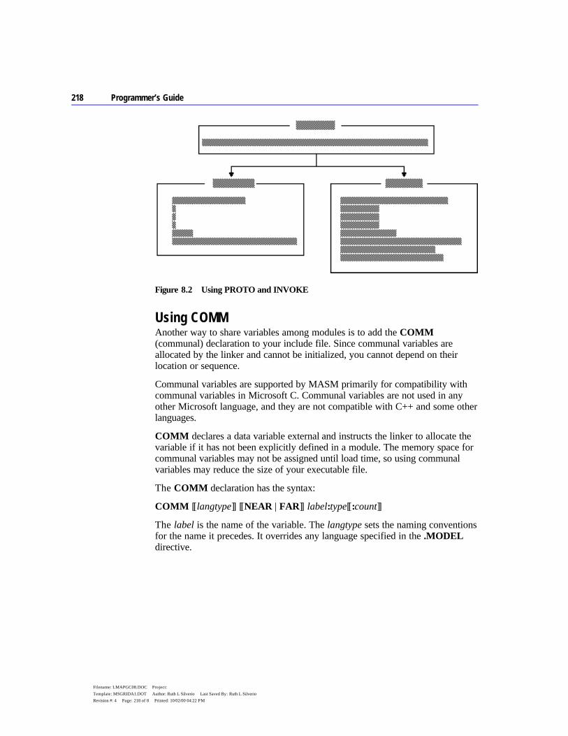
218 Programmer’s Guide
Filename: LMAPGC08.DOC Project: Template: MSGRIDA1.DOT Author: Ruth L Silverio Last Saved By: Ruth L Silverio Revision #: 4 Page: 218 of 8 Printed: 10/02/00 04:22 PM
Figure 8.2 Using PROTO and INVOKE
Using COMM Another way to share variables among modules is to add the COMM (communal) declaration to your include file. Since communal variables are allocated by the linker and cannot be initialized, you cannot depend on their location or sequence.
Communal variables are supported by MASM primarily for compatibility with communal variables in Microsoft C. Communal variables are not used in any other Microsoft language, and they are not compatible with C++ and some other languages.
COMM declares a data variable external and instructs the linker to allocate the variable if it has not been explicitly defined in a module. The memory space for communal variables may not be assigned until load time, so using communal variables may reduce the size of your executable file.
The COMM declaration has the syntax:
COMM [[langtype]] [[NEAR | FAR]] label:type[[:count]]
The label is the name of the variable. The langtype sets the naming conventions for the name it precedes. It overrides any language specified in the .MODEL directive.
Chapter 8 Sharing Data and Procedures Among Modules and Libraries 219
Filename: LMAPGC08.DOC Project: Template: MSGRIDA1.DOT Author: Ruth L Silverio Last Saved By: Ruth L Silverio Revision #: 4 Page: 219 of 9 Printed: 10/02/00 04:22 PM
If NEAR or FAR is not specified, the variable determines the default from the current memory model (NEAR for TINY, SMALL, COMPACT, and FLAT; FAR for MEDIUM, LARGE, and HUGE). If you do not provide a memory model with the .MODEL directive, you must specify a distance when accessing a communal variable, like this:
mov ax, NEAR PTR CommNear mov bx, FAR PTR CommFar
The type can be a constant expression, but it is usually a type such as BYTE, WORD, or DWORD, or a structure, union, or record. If you first declare the type with TYPEDEF, CodeView can provide type information. The count is the number of elements. If no count is given, one element is assumed.
The following example creates the on far variable DataBlock, which is a 1,024-element array of uninitialized signed doublewords:
COMM FAR DataBlock:SDWORD:1024
C variables declared outside functions (except static variables) are communal unless explicitly initialized; they are the same as assembly-language communal variables. If you are writing assembly-language modules for C, you can declare the same communal variables in both C and MASM include files. However, communal variables in C do not have to be declared communal in assembler. The linker will match the EXTERN, PUBLIC, and COMM statements for the variable.
EXTERNDEF (explained in the previous section) is more flexible than COMM because you can initialize variables defined with it, and your code can rely on the position and sequence of the defined data.
Positioning External Declarations Although LINK determines the actual address of an external symbol, the assembler assumes a default segment for the symbol, based on the location of the external directive in the source code. You should therefore position EXTERN and EXTERNDEF directives according to these rules:
u If you know which segment defines an external symbol, put the EXTERN statement in that segment.
Note

220 Programmer’s Guide
Filename: LMAPGC08.DOC Project: Template: MSGRIDA1.DOT Author: Ruth L Silverio Last Saved By: Ruth L Silverio Revision #: 4 Page: 220 of 10 Printed: 10/02/00 04:22 PM
u If you know the group but not the segment, position the EXTERN statement outside any segment and reference the variable with the group name. For example, if var1 is in DGROUP, reference the variable as mov DGROUP:var1, 10
u If you know nothing about the location of an external variable, put the EXTERN statement outside any segment. You can use the SEG directive to access the external variable like this: mov ax, SEG var1 mov es, ax mov ax, es:var1
u If the symbol is an absolute symbol or a far code label, you can declare it external anywhere in the source code.
Always close any segments opened in include files so that external declarations following an include statement are not incorrectly placed inside a segment. If you want to be certain an external definition lies outside a segment, you can use @CurSeg. The @CurSeg predefined symbol returns a blank if the definition is not in a segment. For example,
.DATA . . . @CurSeg ENDS ; Close segment EXTERNDEF var:WORD
For information about predefined symbols such as @CurSeg, see “Predefined Symbols,” page 10.
Using Alternatives to Include Files If your project uses only two modules (or if it is written with a version of MASM prior to 6.0), you may want to continue using PUBLIC in the defining module and EXTERN in the referencing module, and not create an include file for the project. The EXTERN directive can be used in an include file, but the include file containing EXTERN cannot be added to the module that contains the corresponding PUBLIC directive for that symbol. This section assumes that you are not using include files.
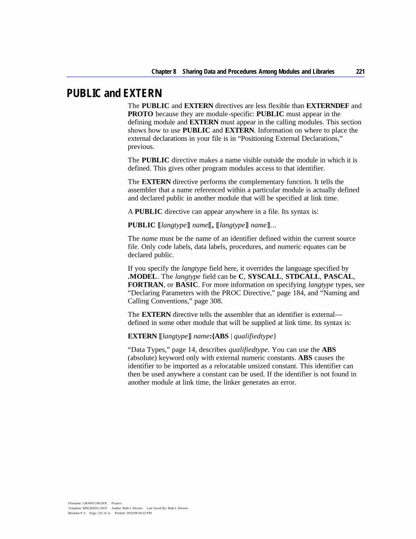
Chapter 8 Sharing Data and Procedures Among Modules and Libraries 221
Filename: LMAPGC08.DOC Project: Template: MSGRIDA1.DOT Author: Ruth L Silverio Last Saved By: Ruth L Silverio Revision #: 4 Page: 221 of 11 Printed: 10/02/00 04:22 PM
PUBLIC and EXTERN The PUBLIC and EXTERN directives are less flexible than EXTERNDEF and PROTO because they are module-specific: PUBLIC must appear in the defining module and EXTERN must appear in the calling modules. This section shows how to use PUBLIC and EXTERN. Information on where to place the external declarations in your file is in “Positioning External Declarations,” previous.
The PUBLIC directive makes a name visible outside the module in which it is defined. This gives other program modules access to that identifier.
The EXTERN directive performs the complementary function. It tells the assembler that a name referenced within a particular module is actually defined and declared public in another module that will be specified at link time.
A PUBLIC directive can appear anywhere in a file. Its syntax is:
PUBLIC [[langtype]] name[[, [[langtype]] name]]...
The name must be the name of an identifier defined within the current source file. Only code labels, data labels, procedures, and numeric equates can be declared public.
If you specify the langtype field here, it overrides the language specified by .MODEL. The langtype field can be C, SYSCALL, STDCALL, PASCAL, FORTRAN, or BASIC. For more information on specifying langtype types, see “Declaring Parameters with the PROC Directive,” page 184, and “Naming and Calling Conventions,” page 308.
The EXTERN directive tells the assembler that an identifier is external — defined in some other module that will be supplied at link time. Its syntax is:
EXTERN [[langtype]] name:{ABS | qualifiedtype}
“Data Types,” page 14, describes qualifiedtype. You can use the ABS (absolute) keyword only with external numeric constants. ABS causes the identifier to be imported as a relocatable unsized constant. This identifier can then be used anywhere a constant can be used. If the identifier is not found in another module at link time, the linker generates an error.
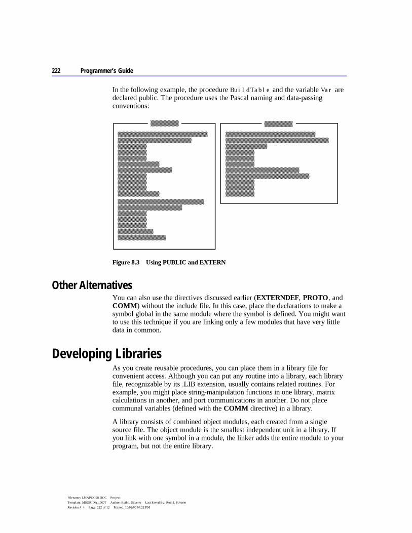
222 Programmer’s Guide
Filename: LMAPGC08.DOC Project: Template: MSGRIDA1.DOT Author: Ruth L Silverio Last Saved By: Ruth L Silverio Revision #: 4 Page: 222 of 12 Printed: 10/02/00 04:22 PM
In the following example, the procedure BuildTable and the variable Var are declared public. The procedure uses the Pascal naming and data-passing conventions:
Figure 8.3 Using PUBLIC and EXTERN
Other Alternatives You can also use the directives discussed earlier (EXTERNDEF, PROTO, and COMM) without the include file. In this case, place the declarations to make a symbol global in the same module where the symbol is defined. You might want to use this technique if you are linking only a few modules that have very little data in common.
Developing Libraries As you create reusable procedures, you can place them in a library file for convenient access. Although you can put any routine into a library, each library file, recognizable by its .LIB extension, usually contains related routines. For example, you might place string-manipulation functions in one library, matrix calculations in another, and port communications in another. Do not place communal variables (defined with the COMM directive) in a library.
A library consists of combined object modules, each created from a single source file. The object module is the smallest independent unit in a library. If you link with one symbol in a module, the linker adds the entire module to your program, but not the entire library.

Chapter 8 Sharing Data and Procedures Among Modules and Libraries 223
Filename: LMAPGC08.DOC Project: Template: MSGRIDA1.DOT Author: Ruth L Silverio Last Saved By: Ruth L Silverio Revision #: 4 Page: 223 of 13 Printed: 10/02/00 04:22 PM
Associating Libraries with Modules You can choose either of two methods for associating your libraries with the modules that use them: you can use the INCLUDELIB directive inside your source files, or link the modules from the command line.
To associate a specified library with your object code, use INCLUDELIB. You can add this directive to the source file to specify the libraries you want linked, rather than specifying them in the LINK command line. The INCLUDELIB syntax is:
INCLUDELIB libraryname
The libraryname can be a file name or a complete path specification. If you do not specify an extension, .LIB is assumed. The libraryname is placed in the comment record of the object file. LINK reads this record and links with the specified library file.
For example, the statement INCLUDELIB GRAPHICS passes a message from the assembler to the linker telling LINK to use library routines from the file GRAPHICS.LIB. If you place this statement in the source file DRAW.ASM and GRAPHICS.LIB is in the same directory, you can assemble and link the program with the following command:
ML DRAW.ASM
Without the INCLUDELIB directive, you must link the program DRAW.ASM with either of the following commands:
ML DRAW.ASM GRAPHICS.LIB ML DRAW /link GRAPHICS
If you want to assemble and link separately, type
ML /c DRAW.ASM LINK DRAW,,,GRAPHICS
If you do not specify a complete path in the INCLUDELIB statement or at the command line, LINK searches for the library file in the following order:
1. In the current directory. 2. In any directories in the library field of the LINK command line. 3. In any directories specified by the LIB environment variable.
The LIB.EXE utility helps you create, organize, and maintain run-time libraries. Refer to Environment and Tools for instructions on LIB.EXE.
224 Programmer’s Guide
Filename: LMAPGC08.DOC Project: Template: MSGRIDA1.DOT Author: Ruth L Silverio Last Saved By: Ruth L Silverio Revision #: 4 Page: 224 of 14 Printed: 10/02/00 04:22 PM
Using EXTERN with Library Routines In some cases, EXTERN helps you limit the size of your executable file by specifying in the syntax an alternative name for a procedure. You would use this form of the EXTERN directive when declaring a procedure or symbol that may not need to be used.
The syntax looks like this:
EXTERN [[langtype]] name [[ (altname) ]] :qualifiedtype
The addition of the altname to the syntax provides the name of an alternate procedure that the linker uses to resolve the external reference if the procedure given by name is not needed. Both name and altname must have the same qualifiedtype.
When the linker encounters an external definition for a procedure that gives an altname, the linker finishes processing that module before it links the object module that contains the procedure given by name. If the program does not reference any symbols in the name file’s object from any of the linked modules, the linker uses altname to satisfy the external reference. This saves space because the library object module is not brought in.
For example, assume that the contents of STARTUP.ASM include these statements:
EXTERN init(dummy):PROC . . . dummy PROC . . . ; A procedure definition containing no ret ; executable code dummy ENDP . . . call init ; Defined in FLOAT.OBJ
In this example, the reference to the routine init (defined in FLOAT.OBJ) does not force the module FLOAT.OBJ to be linked into the executable file. If another reference causes FLOAT.OBJ to be linked into the executable file, then init will refer to the init label in FLOAT.OBJ. If there are no references that force linkage with FLOAT.OBJ, the linker will use the alternate name for init(dummy).


224 Programmer’s Guide
Filename: LMAPGC08.DOC Project: Template: MSGRIDA1.DOT Author: Ruth L Silverio Last Saved By: Ruth L Silverio Revision #: 4 Page: 224 of 16 Printed: 10/02/00 04:22 PM
225
Filename: LMAPGC09.DOC Project: Template: MSGRIDA1.DOT Author: rick debroux Last Saved By: Ruth L Silverio Revision #: 86 Page: 225 of 1 Printed: 10/02/00 04:22 PM
C H A P T E R 9
A “macro” is a symbolic name you give to a series of characters (a text macro) or to one or more statements (a macro procedure or function). As the assembler evaluates each line of your program, it scans the source code for names of previously defined macros. When it finds one, it substitutes the macro text for the macro name. In this way, you can avoid writing the same code several places in your program.
This chapter describes the following types of macros:
u Text macros, which expand to text within a source statement. u Macro procedures, which expand to one or more complete statements and
can optionally take parameters. u Repeat blocks, which generate a group of statements a specified number of
times or until a specified condition becomes true. u Macro functions, which look like macro procedures and can be used like text
macros but which also return a value. u Predefined macro functions and string directives, which perform string
operations.
This chapter explains how to use macros for simple code substitutions and how to write sophisticated macros with parameter lists and repeat loops. It also describes how to use these features in conjunction with local symbols, macro operators, and predefined macro functions.
Using Macros
226 Programmer’s Guide
Filename: LMAPGC09.DOC Project: Template: MSGRIDA1.DOT Author: rick debroux Last Saved By: Ruth L Silverio Revision #: 86 Page: 226 of 2 Printed: 10/02/00 04:22 PM
Text Macros You can give a sequence of characters a symbolic name and then use the name in place of the text later in the source code. The named text is called a text macro.
The TEXTEQU directive defines a text macro, as these examples show:
name TEXTEQU <text> name TEXTEQU macroId | textmacro name TEXTEQU %constExpr
In the previous lines, text is a sequence of characters enclosed in angle brackets, macroId is a previously defined macro function, textmacro is a previously defined text macro, and %constExpr is an expression that evaluates to text.
Here are some examples:
msg TEXTEQU <Some text> ; Text assigned to symbol string TEXTEQU msg ; Text macro assigned to symbol msg TEXTEQU <Some other text> ; New text assigned to symbol value TEXTEQU %(3 + num) ; Text representation of resolved ; expression assigned to symbol
The first line assigns text to the symbol msg. The second line equates the text of the msg text macro with a new text macro called string. The third line assigns new text to msg. Although msg has new text, string retains its original text value. The fourth line assigns 7 to value if num equals 4. If a text macro expands to another text macro (or macro function, as discussed on page 248), the resulting text macro will expand recursively.
Text macros are useful for naming strings of text that do not evaluate to integers. For example, you might use a text macro to name a floating-point constant or a bracketed expression. Here are some practical examples:
pi TEXTEQU <3.1416> ; Floating point constant WPT TEXTEQU <WORD PTR> ; Sequence of key words arg1 TEXTEQU <[bp+4]> ; Bracketed expression
Macro Procedures If your program must perform the same task many times, you can avoid repeatedly typing the same statements each time by writing a macro procedure. Think of macro procedures (commonly called macros) as text-processing mechanisms that automatically generate repeated text.

Chapter 9 Using Macros 227
Filename: LMAPGC09.DOC Project: Template: MSGRIDA1.DOT Author: rick debroux Last Saved By: Ruth L Silverio Revision #: 86 Page: 227 of 3 Printed: 10/02/00 04:22 PM
This section uses the term “macro procedure” rather than “macro” when necessary to distinguish between a macro procedure and a macro function. Macro functions are described in “Returning Values with Macro Functions.”
Conforming to common usage, this chapter occasionally speaks of “calling” a macro, a term that deserves further scrutiny. It’s natural to think of a program calling a macro procedure in the same way it calls a normal subroutine procedure, because they seem to perform identically. However, a macro is simply a representative for real code. Wherever a macro name appears in your program, so in reality does all the code the macro represents. A macro does not cause the processor to vector off to a new location as does a normal procedure. Thus, the expression “calling a macro” may imply the effect, but does not accurately describe what actually occurs.
Creating Macro Procedures You can define a macro procedure without parameters by placing the desired statements between the MACRO and ENDM directives:
name MACRO statements ENDM
For example, suppose you want a program to beep when it encounters certain errors. You could define a beep macro as follows:
beep MACRO mov ah, 2 ;; Select DOS Print Char function mov dl, 7 ;; Select ASCII 7 (bell) int 21h ;; Call DOS ENDM
The double semicolons mark the beginning of macro comments. Macro comments appear in a listing file only at the macro’s initial definition, not at the point where the macro is referenced and expanded. Listings are usually easier to read if the comments aren’t repeatedly expanded. However, regular comments (those with a single semicolon) are listed in macro expansions. See Appendix C for listing files and examples of how macros are expanded in listings.
Once you define a macro, you can call it anywhere in the program by using the macro’s name as a statement. The following example calls the beep macro two times if an error flag has been set.
.IF error ; If error flag is true beep ; execute macro two times beep .ENDIF
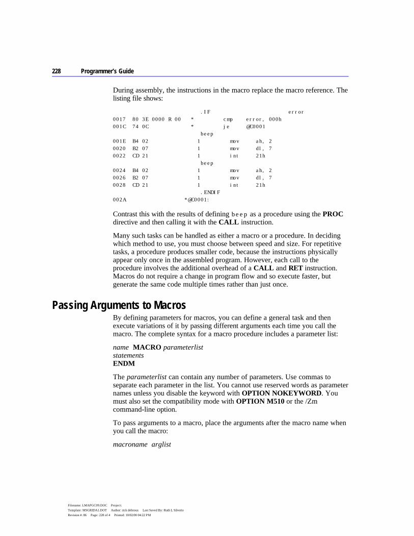
228 Programmer’s Guide
Filename: LMAPGC09.DOC Project: Template: MSGRIDA1.DOT Author: rick debroux Last Saved By: Ruth L Silverio Revision #: 86 Page: 228 of 4 Printed: 10/02/00 04:22 PM
During assembly, the instructions in the macro replace the macro reference. The listing file shows:
.IF error 0017 80 3E 0000 R 00 * cmp error, 000h 001C 74 0C * je @C0001 beep 001E B4 02 1 mov ah, 2 0020 B2 07 1 mov dl, 7 0022 CD 21 1 int 21h beep 0024 B4 02 1 mov ah, 2 0026 B2 07 1 mov dl, 7 0028 CD 21 1 int 21h .ENDIF 002A *@C0001:
Contrast this with the results of defining beep as a procedure using the PROC directive and then calling it with the CALL instruction.
Many such tasks can be handled as either a macro or a procedure. In deciding which method to use, you must choose between speed and size. For repetitive tasks, a procedure produces smaller code, because the instructions physically appear only once in the assembled program. However, each call to the procedure involves the additional overhead of a CALL and RET instruction. Macros do not require a change in program flow and so execute faster, but generate the same code multiple times rather than just once.
Passing Arguments to Macros By defining parameters for macros, you can define a general task and then execute variations of it by passing different arguments each time you call the macro. The complete syntax for a macro procedure includes a parameter list:
name MACRO parameterlist statements ENDM
The parameterlist can contain any number of parameters. Use commas to separate each parameter in the list. You cannot use reserved words as parameter names unless you disable the keyword with OPTION NOKEYWORD. You must also set the compatibility mode with OPTION M510 or the /Zm command-line option.
To pass arguments to a macro, place the arguments after the macro name when you call the macro:
macroname arglist
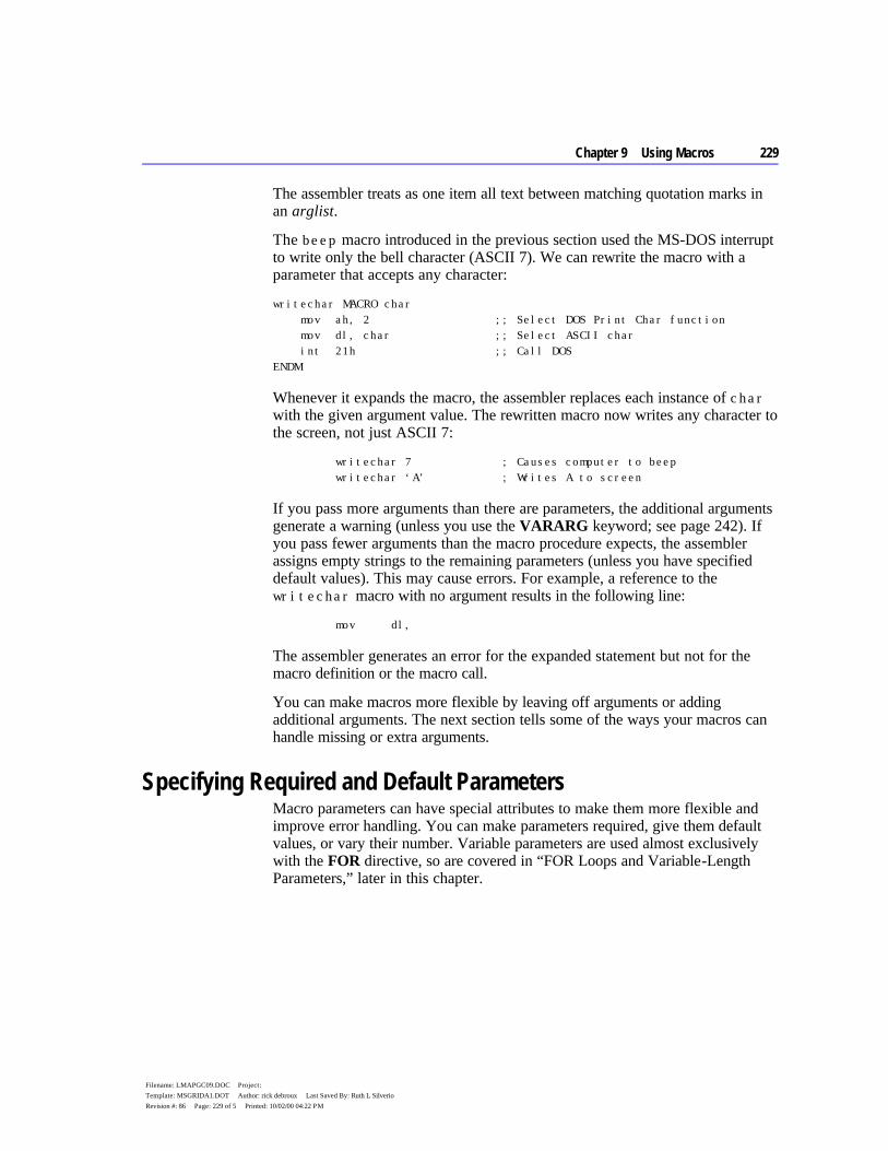
Chapter 9 Using Macros 229
Filename: LMAPGC09.DOC Project: Template: MSGRIDA1.DOT Author: rick debroux Last Saved By: Ruth L Silverio Revision #: 86 Page: 229 of 5 Printed: 10/02/00 04:22 PM
The assembler treats as one item all text between matching quotation marks in an arglist.
The beep macro introduced in the previous section used the MS-DOS interrupt to write only the bell character (ASCII 7). We can rewrite the macro with a parameter that accepts any character:
writechar MACRO char mov ah, 2 ;; Select DOS Print Char function mov dl, char ;; Select ASCII char int 21h ;; Call DOS ENDM
Whenever it expands the macro, the assembler replaces each instance of char with the given argument value. The rewritten macro now writes any character to the screen, not just ASCII 7:
writechar 7 ; Causes computer to beep writechar ‘A’ ; Writes A to screen
If you pass more arguments than there are parameters, the additional arguments generate a warning (unless you use the VARARG keyword; see page 242). If you pass fewer arguments than the macro procedure expects, the assembler assigns empty strings to the remaining parameters (unless you have specified default values). This may cause errors. For example, a reference to the writechar macro with no argument results in the following line:
mov dl,
The assembler generates an error for the expanded statement but not for the macro definition or the macro call.
You can make macros more flexible by leaving off arguments or adding additional arguments. The next section tells some of the ways your macros can handle missing or extra arguments.
Specifying Required and Default Parameters Macro parameters can have special attributes to make them more flexible and improve error handling. You can make parameters required, give them default values, or vary their number. Variable parameters are used almost exclusively with the FOR directive, so are covered in “FOR Loops and Variable-Length Parameters,” later in this chapter.
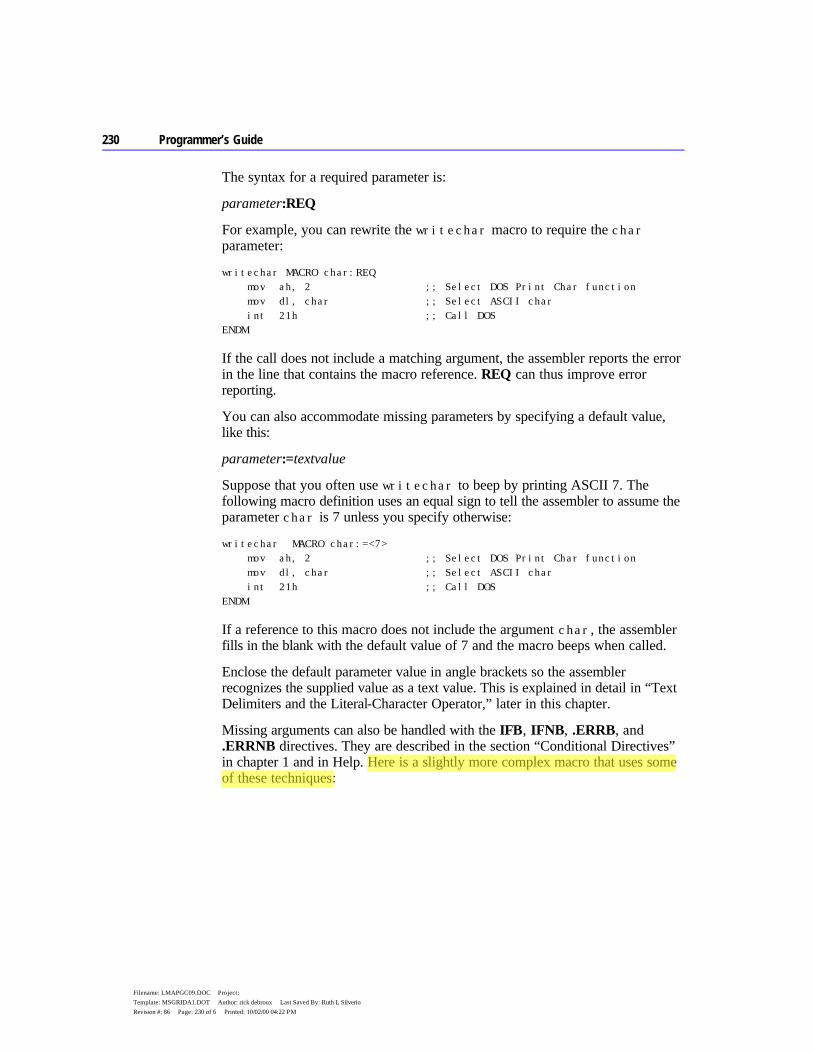
230 Programmer’s Guide
Filename: LMAPGC09.DOC Project: Template: MSGRIDA1.DOT Author: rick debroux Last Saved By: Ruth L Silverio Revision #: 86 Page: 230 of 6 Printed: 10/02/00 04:22 PM
The syntax for a required parameter is:
parameter:REQ
For example, you can rewrite the writechar macro to require the char parameter:
writechar MACRO char:REQ mov ah, 2 ;; Select DOS Print Char function mov dl, char ;; Select ASCII char int 21h ;; Call DOS ENDM
If the call does not include a matching argument, the assembler reports the error in the line that contains the macro reference. REQ can thus improve error reporting.
You can also accommodate missing parameters by specifying a default value, like this:
parameter:=textvalue
Suppose that you often use writechar to beep by printing ASCII 7. The following macro definition uses an equal sign to tell the assembler to assume the parameter char is 7 unless you specify otherwise:
writechar MACRO char:=<7> mov ah, 2 ;; Select DOS Print Char function mov dl, char ;; Select ASCII char int 21h ;; Call DOS ENDM
If a reference to this macro does not include the argument char, the assembler fills in the blank with the default value of 7 and the macro beeps when called.
Enclose the default parameter value in angle brackets so the assembler recognizes the supplied value as a text value. This is explained in detail in “Text Delimiters and the Literal-Character Operator,” later in this chapter.
Missing arguments can also be handled with the IFB, IFNB, .ERRB, and .ERRNB directives. They are described in the section “Conditional Directives” in chapter 1 and in Help. Here is a slightly more complex macro that uses some of these techniques:
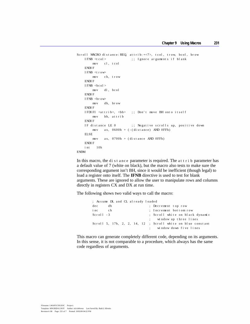
Chapter 9 Using Macros 231
Filename: LMAPGC09.DOC Project: Template: MSGRIDA1.DOT Author: rick debroux Last Saved By: Ruth L Silverio Revision #: 86 Page: 231 of 7 Printed: 10/02/00 04:22 PM
Scroll MACRO distance:REQ, attrib:=<7>, tcol, trow, bcol, brow IFNB <tcol> ;; Ignore arguments if blank mov cl, tcol ENDIF IFNB <trow> mov ch, trow ENDIF IFNB <bcol> mov dl, bcol ENDIF IFNB <brow> mov dh, brow ENDIF IFDIFI <attrib>, <bh> ;; Don’t move BH onto itself mov bh, attrib ENDIF IF distance LE 0 ;; Negative scrolls up, positive down mov ax, 0600h + (-(distance) AND 0FFh) ELSE mov ax, 0700h + (distance AND 0FFh) ENDIF int 10h ENDM
In this macro, the distance parameter is required. The attrib parameter has a default value of 7 (white on black), but the macro also tests to make sure the corresponding argument isn’t BH, since it would be inefficient (though legal) to load a register onto itself. The IFNB directive is used to test for blank arguments. These are ignored to allow the user to manipulate rows and columns directly in registers CX and DX at run time.
The following shows two valid ways to call the macro:
; Assume DL and CL already loaded dec dh ; Decrement top row inc ch ; Increment bottom row Scroll -3 ; Scroll white on black dynamic ; window up three lines Scroll 5, 17h, 2, 2, 14, 12 ; Scroll white on blue constant ; window down five lines
This macro can generate completely different code, depending on its arguments. In this sense, it is not comparable to a procedure, which always has the same code regardless of arguments.
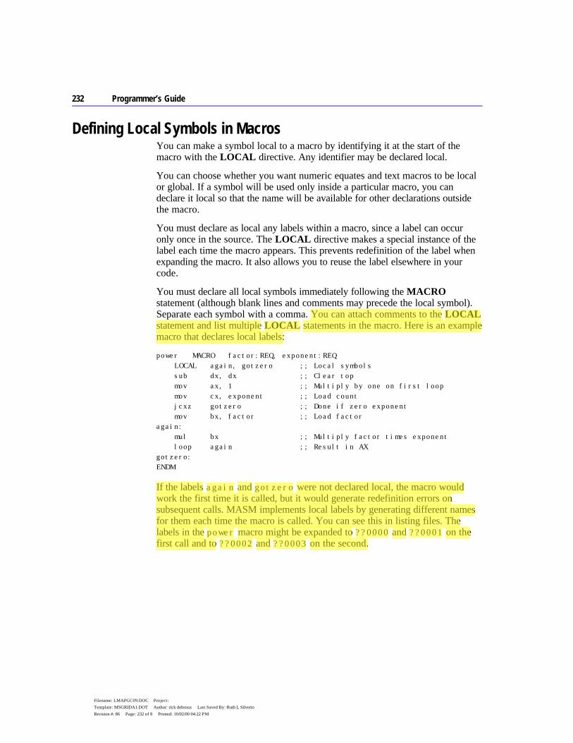
232 Programmer’s Guide
Filename: LMAPGC09.DOC Project: Template: MSGRIDA1.DOT Author: rick debroux Last Saved By: Ruth L Silverio Revision #: 86 Page: 232 of 8 Printed: 10/02/00 04:22 PM
Defining Local Symbols in Macros You can make a symbol local to a macro by identifying it at the start of the macro with the LOCAL directive. Any identifier may be declared local.
You can choose whether you want numeric equates and text macros to be local or global. If a symbol will be used only inside a particular macro, you can declare it local so that the name will be available for other declarations outside the macro.
You must declare as local any labels within a macro, since a label can occur only once in the source. The LOCAL directive makes a special instance of the label each time the macro appears. This prevents redefinition of the label when expanding the macro. It also allows you to reuse the label elsewhere in your code.
You must declare all local symbols immediately following the MACRO statement (although blank lines and comments may precede the local symbol). Separate each symbol with a comma. You can attach comments to the LOCAL statement and list multiple LOCAL statements in the macro. Here is an example macro that declares local labels:
power MACRO factor:REQ, exponent:REQ LOCAL again, gotzero ;; Local symbols sub dx, dx ;; Clear top mov ax, 1 ;; Multiply by one on first loop mov cx, exponent ;; Load count jcxz gotzero ;; Done if zero exponent mov bx, factor ;; Load factor again: mul bx ;; Multiply factor times exponent loop again ;; Result in AX gotzero: ENDM
If the labels again and gotzero were not declared local, the macro would work the first time it is called, but it would generate redefinition errors on subsequent calls. MASM implements local labels by generating different names for them each time the macro is called. You can see this in listing files. The labels in the power macro might be expanded to ??0000 and ??0001 on the first call and to ??0002 and ??0003 on the second.
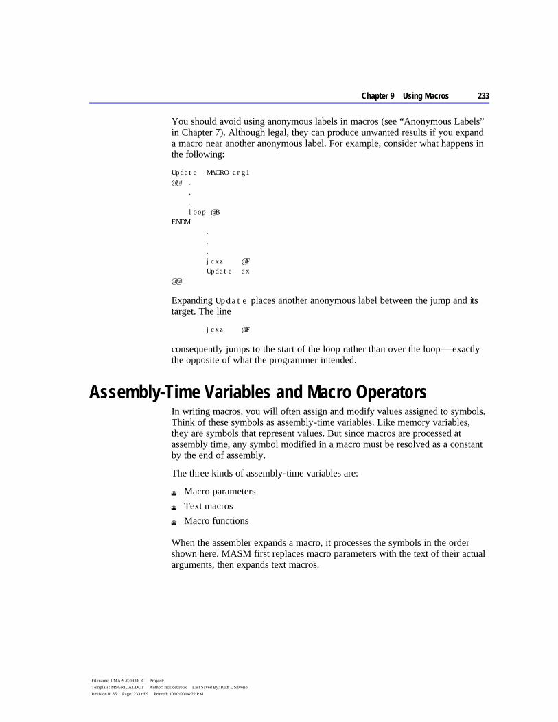
Chapter 9 Using Macros 233
Filename: LMAPGC09.DOC Project: Template: MSGRIDA1.DOT Author: rick debroux Last Saved By: Ruth L Silverio Revision #: 86 Page: 233 of 9 Printed: 10/02/00 04:22 PM
You should avoid using anonymous labels in macros (see “Anonymous Labels” in Chapter 7). Although legal, they can produce unwanted results if you expand a macro near another anonymous label. For example, consider what happens in the following:
Update MACRO arg1 @@: . . . loop @B ENDM . . . jcxz @F Update ax @@:
Expanding Update places another anonymous label between the jump and its target. The line
jcxz @F
consequently jumps to the start of the loop rather than over the loop — exactly the opposite of what the programmer intended.
Assembly-Time Variables and Macro Operators In writing macros, you will often assign and modify values assigned to symbols. Think of these symbols as assembly-time variables. Like memory variables, they are symbols that represent values. But since macros are processed at assembly time, any symbol modified in a macro must be resolved as a constant by the end of assembly.
The three kinds of assembly-time variables are:
u Macro parameters u Text macros u Macro functions
When the assembler expands a macro, it processes the symbols in the order shown here. MASM first replaces macro parameters with the text of their actual arguments, then expands text macros.
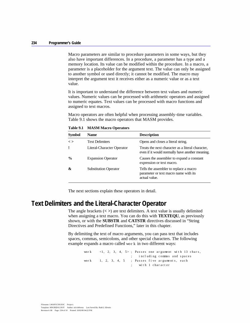
234 Programmer’s Guide
Filename: LMAPGC09.DOC Project: Template: MSGRIDA1.DOT Author: rick debroux Last Saved By: Ruth L Silverio Revision #: 86 Page: 234 of 10 Printed: 10/02/00 04:22 PM
Macro parameters are similar to procedure parameters in some ways, but they also have important differences. In a procedure, a parameter has a type and a memory location. Its value can be modified within the procedure. In a macro, a parameter is a placeholder for the argument text. The value can only be assigned to another symbol or used directly; it cannot be modified. The macro may interpret the argument text it receives either as a numeric value or as a text value.
It is important to understand the difference between text values and numeric values. Numeric values can be processed with arithmetic operators and assigned to numeric equates. Text values can be processed with macro functions and assigned to text macros.
Macro operators are often helpful when processing assembly-time variables. Table 9.1 shows the macro operators that MASM provides.
Table 9.1 MASM Macro Operators
Symbol Name Description
< > Text Delimiters Opens and closes a literal string. ! Literal-Character Operator Treats the next character as a literal character,
even if it would normally have another meaning. % Expansion Operator Causes the assembler to expand a constant
expression or text macro. & Substitution Operator Tells the assembler to replace a macro
parameter or text macro name with its actual value.
The next sections explain these operators in detail.
Text Delimiters and the Literal-Character Operator The angle brackets (< >) are text delimiters. A text value is usually delimited when assigning a text macro. You can do this with TEXTEQU, as previously shown, or with the SUBSTR and CATSTR directives discussed in “String Directives and Predefined Functions,” later in this chapter.
By delimiting the text of macro arguments, you can pass text that includes spaces, commas, semicolons, and other special characters. The following example expands a macro called work in two different ways:
work <1, 2, 3, 4, 5> ; Passes one argument with 13 chars, ; including commas and spaces work 1, 2, 3, 4, 5 ; Passes five arguments, each ; with 1 character

Chapter 9 Using Macros 235
Filename: LMAPGC09.DOC Project: Template: MSGRIDA1.DOT Author: rick debroux Last Saved By: Ruth L Silverio Revision #: 86 Page: 235 of 11 Printed: 10/02/00 04:22 PM
The literal-character operator (!) lets you include angle brackets as part of a delimited text value, so the assembler does not interpret them as delimiters. The assembler treats the character following ! literally rather than as a special character, like this:
errstr TEXTEQU <Expression !> 255> ; errstr = “Expression > 255”
Text delimiters also have a special use with the FOR directive, as explained in “FOR Loops and Variable-Length Parameters,” later in this chapter.
Expansion Operator The expansion operator (%) expands text macros or converts constant expressions into their text representations. It performs these tasks differently in different contexts, as discussed in the following.
Converting Numeric Expressions to Text The expansion operator can convert numbers to text. The operator forces immediate evaluation of a constant expression and replaces it with a text value consisting of the digits of the result. The digits are generated in the current radix (default decimal).
This application of the expansion operator is useful when defining a text macro, as the following lines show. Notice how you can enclose expressions with parentheses to make them more readable:
a TEXTEQU <3 + 4> ; a = “3 + 4” b TEXTEQU %3 + 4 ; b = “7” c TEXTEQU %(3 + 4) ; c = “7”
When assigning text macros, you can use numeric equates in the constant expressions, but not text macros:
num EQU 4 ; num = 4 numstr TEXTEQU <4> ; numstr = <4> a TEXTEQU %3 + num ; a = <7> b TEXTEQU %3 + numstr ; b = <7>
The expansion operator gives you flexibility when passing arguments to macros. It lets you pass a computed value rather than the literal text of an expression. The following example illustrates by defining a macro
work MACRO arg mov ax, arg * 4 ENDM
236 Programmer’s Guide
Filename: LMAPGC09.DOC Project: Template: MSGRIDA1.DOT Author: rick debroux Last Saved By: Ruth L Silverio Revision #: 86 Page: 236 of 12 Printed: 10/02/00 04:22 PM
which accepts different arguments:
work 2 + 3 ; Passes “2 + 3” ; Code: mov ax, 2 + (3 * 4) work %2 + 3 ; Passes 5 ; Code: mov ax, 5 * 4 work 2 + num ; Passes “2 + num” work %2 + num ; Passes “6” work 2 + numstr ; Passes “2 + numstr” work %2 + numstr ; Passes “6”
You must consider operator precedence when using the expansion operator. Parentheses inside the macro can force evaluation in a desired order:
work MACRO arg mov ax, (arg) * 4 ENDM work 2 + 3 ; Code: mov ax, (2 + 3) * 4 work %2 + 3 ; Code: mov ax, (5) * 4
Several other uses for the expansion operator are reviewed in “Returning Values with Macro Functions,” later in this chapter.
Expansion Operator as First Character on a Line The expansion operator has a different meaning when used as the first character on a line. In this case, it instructs the assembler to expand any text macros and macro functions it finds on the rest of the line.
This feature makes it possible to use text macros with directives such as ECHO, TITLE, and SUBTITLE, which take an argument consisting of a single text value. For instance, ECHO displays its argument to the standard output device during assembly. Such expansion can be useful for debugging macros and expressions, but the requirement that its argument be a single text value may have unexpected results. Consider this example:
ECHO Bytes per element: %(SIZEOF array / LENGTHOF array)
Instead of evaluating the expression, this line echoes it:
Bytes per element: %(SIZEOF array / LENGTHOF array)
However, you can achieve the desired result by assigning the text of the expression to a text macro and then using the expansion operator at the beginning of the line to force expansion of the text macro.

Chapter 9 Using Macros 237
Filename: LMAPGC09.DOC Project: Template: MSGRIDA1.DOT Author: rick debroux Last Saved By: Ruth L Silverio Revision #: 86 Page: 237 of 13 Printed: 10/02/00 04:22 PM
temp TEXTEQU %(SIZEOF array / LENGTHOF array) % ECHO Bytes per element: temp
Note that you cannot get the same results simply by putting the % at the beginning of the first echo line, because % expands only text macros, not numeric equates or constant expressions.
Here are more examples of the expansion operator at the start of a line:
; Assume memmod, lang, and os specified with /D option % SUBTITLE Model: memmod Language: lang Operating System: os ; Assume num defined earlier tnum TEXTEQU %num % .ERRE num LE 255, <Failed because tnum !> 255>
Substitution Operator References to a parameter within a macro can sometimes be ambiguous. In such cases, the assembler may not expand the argument as you intend. The substitution operator (&) lets you identify unambiguously any parameter within a macro.
As an example, consider the following macro:
errgen MACRO num, msg PUBLIC errnum errnum BYTE “Error num: msg” ENDM
This macro is open to several interpretations:
u Is errnum a distinct word or the word err next to the parameter num? u Should num and msg within the string be treated literally as part of the string
or as arguments?
In each case, the assembler chooses the most literal interpretation. That is, it treats errnum as a distinct word, and num and msg as literal parts of the string.
The substitution operator can force different interpretations. If we rewrite the macro with the & operator, it looks like this:
errgen MACRO num, msg PUBLIC err&num err&num BYTE “Error &num: &msg” ENDM
238 Programmer’s Guide
Filename: LMAPGC09.DOC Project: Template: MSGRIDA1.DOT Author: rick debroux Last Saved By: Ruth L Silverio Revision #: 86 Page: 238 of 14 Printed: 10/02/00 04:22 PM
When called with the following arguments,
errgen 5, <Unreadable disk>
the macro now generates this code:
PUBLIC err5 err5 BYTE “Error 5: Unreadable disk”
When it encounters the & operator, the assembler interprets subsequent text as a parameter name until the next & or until the next separator character (such as a space, tab, or comma). Thus, the assembler correctly parses the expression err&num because num is delimited by & and a space. The expression could also be written as err&num&, which again unambiguously identifies num as a parameter.
The rule also works in reverse. You can delimit a parameter reference with & at the end rather than at the beginning. For example, if num is 5, the expression num&12 resolves to “512.”
The assembler processes substitution operators from left to right. This can have unexpected results when you are pasting together two macro parameters. For example, if arg1 has the value var and arg2 has the value 3, you could paste them together with this statement:
&arg1&&arg2& BYTE “Text”
Eliminating extra substitution operators, you might expect the following to be equivalent:
&arg1&arg2 BYTE “Text”
However, this actually produces the symbol vararg2, because in processing from left to right, the assembler associates both the first and the second & symbols with the first parameter. The assembler replaces &arg1& by var, producing vararg2. The arg2 is never evaluated. The correct abbreviation is:
arg1&&arg2 BYTE “Text”
which produces the desired symbol var3. The symbol arg1&&arg2 is replaced by var&arg2, which is replaced by var3.
The substitution operator is also necessary if you want to substitute a text macro inside quotes. For example,

Chapter 9 Using Macros 239
Filename: LMAPGC09.DOC Project: Template: MSGRIDA1.DOT Author: rick debroux Last Saved By: Ruth L Silverio Revision #: 86 Page: 239 of 15 Printed: 10/02/00 04:22 PM
arg TEXTEQU <hello> %echo This is a string “&arg” ; Produces: This is a string “hello” %echo This is a string “arg” ; Produces: This is a string “arg”
You can also use the substitution operator in lines beginning with the expansion operator (%) symbol, even outside macros (see page 236). It may be necessary to use the substitution operator to paste text macro names to adjacent characters or symbol names, as shown here:
text TEXTEQU <var> value TEXTEQU %5 % ECHO textvalue is text&&value
This echoes the message
textvalue is var5
Macro substitution always occurs before evaluation of the high-level control structures. The assembler may therefore mistake a bit-test operator (&) in your macro for a substitution operator. You can guarantee the assembler correctly recognizes a bit-test operator by enclosing its operands in parentheses, as shown here:
test MACRO x .IF ax==&x ; &x substituted with parameter value mov ax, 10 .ELSEIF ax&(x) ; & is bitwise AND mov ax, 20 .ENDIF ENDM
The rules for using the substitution operator have changed significantly since MASM 5.1, making macro behavior more consistent and flexible. If you have macros written for MASM 5.1 or earlier, you can specify the old behavior by using OLDMACROS or M510 with the OPTION directive (see page 24).
Defining Repeat Blocks with Loop Directives A “repeat block” is an unnamed macro defined with a loop directive. The loop directive generates the statements inside the repeat block a specified number of times or until a given condition becomes true.
MASM provides several loop directives, which let you specify the number of loop iterations in different ways. Some loop directives can also accept arguments for each iteration. Although the number of iterations is usually specified in the directive, you can use the EXITM directive to exit the loop early.
240 Programmer’s Guide
Filename: LMAPGC09.DOC Project: Template: MSGRIDA1.DOT Author: rick debroux Last Saved By: Ruth L Silverio Revision #: 86 Page: 240 of 16 Printed: 10/02/00 04:22 PM
Repeat blocks can be used outside macros, but they frequently appear inside macro definitions to perform some repeated operation in the macro. Since repeat blocks are macros themselves, they end with the ENDM directive.
Chapter 9 Using Macros 241
Filename: LMAPGC09.DOC Project: Template: MSGRIDA1.DOT Author: rick debroux Last Saved By: Ruth L Silverio Revision #: 86 Page: 241 of 17 Printed: 10/02/00 04:22 PM
This section explains the following four loop directives: REPEAT, WHILE, FOR, and FORC. In versions of MASM prior to 6.0, REPEAT was called REPT, FOR was called IRP, and FORC was called IRPC. MASM 6.1 recognizes the old names.
The assembler evaluates repeat blocks on the first pass only. You should therefore avoid using address spans as loop counters, as in this example:
REPEAT (OFFSET label1 - OFFSET label2) ; Don't do this!
Since the distance between two labels may change on subsequent assembly passes as the assembler optimizes code, you should not assume that address spans remain constant between passes.
The REPEAT and WHILE directives should not be confused with the REPEAT and WHILE directives (see “Loop-Generating Directives” in Chapter 7), which generate loop and jump instructions for run-time program control.
REPEAT Loops REPEAT is the simplest loop directive. It specifies the number of times to generate the statements inside the macro. The syntax is:
REPEAT constexpr statements ENDM
The constexpr can be a constant or a constant expression, and must contain no forward references. Since the repeat block expands at assembly time, the number of iterations must be known then.
Here is an example of a repeat block used to generate data. It initializes an array containing sequential ASCII values for all uppercase letters.
alpha LABEL BYTE ; Name the data generated letter = ‘A’ ; Initialize counter REPEAT 26 ;; Repeat for each letter BYTE letter ;; Allocate ASCII code for letter letter = letter + 1 ;; Increment counter ENDM
Note
242 Programmer’s Guide
Filename: LMAPGC09.DOC Project: Template: MSGRIDA1.DOT Author: rick debroux Last Saved By: Ruth L Silverio Revision #: 86 Page: 242 of 18 Printed: 10/02/00 04:22 PM
Here is another use of REPEAT, this time inside a macro:
beep MACRO iter:=<3> mov ah, 2 ;; Character output function mov dl, 7 ;; Bell character REPEAT iter ;; Repeat number specified by macro int 21h ;; Call DOS ENDM ENDM
WHILE Loops The WHILE directive is similar to REPEAT, but the loop continues as long as a given condition is true. The syntax is:
WHILE expression statements ENDM
The expression must be a value that can be calculated at assembly time. Normally, the expression uses relational operators, but it can be any expression that evaluates to zero (false) or nonzero (true). Usually, the condition changes during the evaluation of the macro so that the loop won’t attempt to generate an infinite amount of code. However, you can use the EXITM directive to break out of the loop.
The following repeat block uses the WHILE directive to allocate variables initialized to calculated values. This is a common technique for generating lookup tables. (A lookup table is any list of precalculated results, such as a table of interest payments or trigonometric values or logarithms. Programs optimized for speed often use lookup tables, since calculating a value often takes more time than looking it up in a table.)
cubes LABEL BYTE ;; Name the data generated root = 1 ;; Initialize root cube = root * root * root ;; Calculate first cube WHILE cube LE 32767 ;; Repeat until result too large WORD cube ;; Allocate cube root = root + 1 ;; Calculate next root and cube cube = root * root * root ENDM
Chapter 9 Using Macros 243
Filename: LMAPGC09.DOC Project: Template: MSGRIDA1.DOT Author: rick debroux Last Saved By: Ruth L Silverio Revision #: 86 Page: 243 of 19 Printed: 10/02/00 04:22 PM
FOR Loops and Variable-Length Parameters With the FOR directive you can iterate through a list of arguments, working on each of them in turn. It has the following syntax:
FOR parameter, <argumentlist> statements ENDM
The parameter is a placeholder that represents the name of each argument inside the FOR block. The argument list must contain comma-separated arguments and must always be enclosed in angle brackets. Here’s an example of a FOR block:
series LABEL BYTE FOR arg, <1,2,3,4,5,6,7,8,9,10> BYTE arg DUP (arg) ENDM
On the first iteration, the arg parameter is replaced with the first argument, the value 1. On the second iteration, arg is replaced with 2. The result is an array with the first byte initialized to 1, the next 2 bytes initialized to 2, the next 3 bytes initialized to 3, and so on.
The argument list is given specifically in this example, but in some cases the list must be generated as a text macro. The value of the text macro must include the angle brackets.
arglist TEXTEQU <!<3,6,9!>> ; Generate list as text macro %FOR arg, arglist . ; Do something to arg . . ENDM
Note the use of the literal character operator (!) to identify angle brackets as characters, not delimiters. See “Text Delimiters (< >) and the Literal-Character Operator,” earlier in this chapter.
The FOR directive also provides a convenient way to process macros with a variable number of arguments. To do this, add VARARG to the last parameter to indicate that a single named parameter will have the actual value of all additional arguments. For example, the following macro definition includes the three possible parameter attributes — required, default, and variable.
work MACRO rarg:REQ, darg:=<5>, varg:VARARG
244 Programmer’s Guide
Filename: LMAPGC09.DOC Project: Template: MSGRIDA1.DOT Author: rick debroux Last Saved By: Ruth L Silverio Revision #: 86 Page: 244 of 20 Printed: 10/02/00 04:22 PM
The variable argument must always be last. If this macro is called with the statement
work 4, , 6, 7, a, b
the first argument is received as the value 4, the second is replaced by the default value 5, and the last four are received as the single argument <6, 7, a, b>. This is the same format expected by the FOR directive. The FOR directive discards leading spaces but recognizes trailing spaces.
The following macro illustrates variable arguments:
show MACRO chr:VARARG mov ah, 02h FOR arg, <chr> mov dl, arg int 21h ENDM ENDM
When called with
show ‘O’, ‘K’, 13, 10
the macro displays each of the specified characters one at a time.
The parameter in a FOR loop can have the required or default attribute. You can modify the show macro to make blank arguments generate errors:
show MACRO chr:VARARG mov ah, 02h FOR arg:REQ, <chr> mov dl, arg int 21h ENDM ENDM
The macro now generates an error if called with
show ‘O’,, ‘K’, 13, 10
Chapter 9 Using Macros 245
Filename: LMAPGC09.DOC Project: Template: MSGRIDA1.DOT Author: rick debroux Last Saved By: Ruth L Silverio Revision #: 86 Page: 245 of 21 Printed: 10/02/00 04:22 PM
Another approach would be to use a default argument:
show MACRO chr:VARARG mov ah, 02h FOR arg:=<‘ ’>, <chr> mov dl, arg int 21h ENDM ENDM
Now calling the macro with
show ‘O’,, ‘K’, 13, 10
inserts the default character, a space, for the blank argument.
FORC Loops The FORC directive is similar to FOR, but takes a string of text rather than a list of arguments. The statements are assembled once for each character (including spaces) in the string, substituting a different character for the parameter each time through.
The syntax looks like this:
FORC parameter, < text> statements ENDM
The text must be enclosed in angle brackets. The following example illustrates FORC:
FORC arg, <ABCDEFGHIJKLMNOPQRSTUVWXYZ> BYTE ‘&arg’ ;; Allocate uppercase letter BYTE ‘&arg’ + 20h ;; Allocate lowercase letter BYTE ‘&arg’ - 40h ;; Allocate ordinal of letter ENDM
Notice that the substitution operator must be used inside the quotation marks to make sure that arg is expanded to a character rather than treated as a literal string.
With versions of MASM earlier than 6.0, FORC is often used for complex parsing tasks. A long sentence can be examined character by character. Each character is then either thrown away or pasted onto a token string, depending on whether it is a separator character. The new predefined macro functions and string processing directives discussed in the following section are usually more efficient for these tasks.
246 Programmer’s Guide
Filename: LMAPGC09.DOC Project: Template: MSGRIDA1.DOT Author: rick debroux Last Saved By: Ruth L Silverio Revision #: 86 Page: 246 of 22 Printed: 10/02/00 04:22 PM
String Directives and Predefined Functions The assembler provides four directives for manipulating text:
Directive Description
SUBSTR Assigns part of string to a new symbol. INSTR Searches for one string within another. SIZESTR Determines the size of a string. CATSTR Concatenates one or more strings to a single string.
These directives assign a processed value to a text macro or numeric equate. For example, the following lines
num = 7 newstr CATSTR <3 + >, %num, < = > , %3 + num ; "3 + 7 = 10"
assign the string "3 + 7 = 10" to newstr. CATSTR and SUBSTR assign text in the same way as the TEXTEQU directive. SIZESTR and INSTR assign a number in the same way as the = operator. The four string directives take only text values as arguments. Use the expansion operator (%) when you need to make sure that constants and numeric equates expand to text, as shown in the preceding lines.
Each of the string directives has a corresponding predefined macro function version: @SubStr, @InStr, @SizeStr, and @CatStr. Macro functions are similar to the string directives, but you must enclose their arguments in parentheses. Macro functions return text values and can appear in any context where text is expected. The following section, “Returning Values with Macro Functions,” tells how to write your own macro functions. The following example is equivalent to the previous CATSTR example:
num = 7 newstr TEXTEQU @CatStr( <3 + >, %num, < = > , %3 + num )
Macro functions are often more convenient than their directive counterparts because you can use a macro function as an argument to a string directive or to another macro function. Unlike string directives, predefined macro function names are case sensitive when you use the /Cp command-line option.
Each string directive and predefined function acts on a string, which can be any textItem. The textItem can be text enclosed in angle brackets (< >), the name of a text macro, or a constant expression preceded by % (as in %constExpr). Refer to Appendix B, “BNF Grammar,” for a list of types that textItem can represent.
Chapter 9 Using Macros 247
Filename: LMAPGC09.DOC Project: Template: MSGRIDA1.DOT Author: rick debroux Last Saved By: Ruth L Silverio Revision #: 86 Page: 247 of 23 Printed: 10/02/00 04:22 PM
The following sections summarize the syntax for each of the string directives and functions. The explanations focus on the directives, but the functions work the same except where noted.
SUBSTR name SUBSTR string, start[[, length]] @SubStr( string, start[[, length]] )
The SUBSTR directive assigns a substring from a given string to the symbol name. The start parameter specifies the position in string, beginning with 1, to start the substring. The length gives the length of the substring. If you do not specify length, SUBSTR returns the remainder of the string, including the start character.
INSTR name INSTR [[start,]] string, substring @InStr( [[start]], string, substring )
The INSTR directive searches a specified string for an occurrence of substring and assigns its position number to name. The search is case sensitive. The start parameter is the position in string to start the search for substring. If you do not specify start, it is assumed to be position 1, the start of the string. If INSTR does not find substring, it assigns position 0 to name.
The INSTR directive assigns the position value name as if it were a numeric equate. In contrast, the @InStr returns the value as a string of digits in the current radix.
The @InStr function has a slightly different syntax than the INSTR directive. You can omit the first argument and its associated comma from the directive. You can leave the first argument blank with the function, but a blank function argument must still have a comma. For example,
pos INSTR <person>, <son>
is the same as
pos = @InStr( , <person>, <son> )
You can also assign the return value to a text macro, like this:
248 Programmer’s Guide
Filename: LMAPGC09.DOC Project: Template: MSGRIDA1.DOT Author: rick debroux Last Saved By: Ruth L Silverio Revision #: 86 Page: 248 of 24 Printed: 10/02/00 04:22 PM
strpos TEXTEQU @InStr( , <person>, <son> )
SIZESTR name SIZESTR string @SizeStr( string )
The SIZESTR directive assigns the number of characters in string to name. An empty string returns a length of zero. The SIZESTR directive assigns the size value to a name as if it were a numeric equate. The @SizeStr function returns the value as a string of digits in the current radix.
CATSTR name CATSTR string[, string]... @CatStr( string[, string]... )
The CATSTR directive concatenates a list of text values into a single text value and assigns it to name. TEXTEQU is technically a synonym for CATSTR. TEXTEQU is normally used for single-string assignments, while CATSTR is used for multistring concatenations.
The following example pushes and pops one set of registers, illustrating several uses of string directives and functions:
Chapter 9 Using Macros 249
Filename: LMAPGC09.DOC Project: Template: MSGRIDA1.DOT Author: rick debroux Last Saved By: Ruth L Silverio Revision #: 86 Page: 249 of 25 Printed: 10/02/00 04:22 PM
; SaveRegs - Macro to generate a push instruction for each ; register in argument list. Saves each register name in the ; regpushed text macro. regpushed TEXTEQU <> ;; Initialize empty string SaveRegs MACRO regs:VARARG LOCAL reg FOR reg, <regs> ;; Push each register push reg ;; and add it to the list regpushed CATSTR <reg>, <,>, regpushed ENDM ;; Strip off last comma regpushed CATSTR <!<>, regpushed ;; Mark start of list with < regpushed SUBSTR regpushed, 1, @SizeStr( regpushed ) regpushed CATSTR regpushed, <!>> ;; Mark end with > ENDM ; RestoreRegs - Macro to generate a pop instruction for registers ; saved by the SaveRegs macro. Restores one group of registers. RestoreRegs MACRO LOCAL reg %FOR reg, regpushed ;; Pop each register pop reg ENDM ENDM
Notice how the SaveRegs macro saves its result in the regpushed text macro for later use by the RestoreRegs macro. In this case, a text macro is used as a global variable. By contrast, the reg text macro is used only in RestoreRegs. It is declared LOCAL so it won’t take the name reg from the global name space. The MACROS.INC file provided with MASM 6.1 includes expanded versions of these same two macros.
Returning Values with Macro Functions A macro function is a named group of statements that returns a value. When calling a macro function, you must enclose its argument list in parentheses, even if the list is empty. The function always returns text.
MASM 6.1 provides several predefined macro functions for common tasks. The predefined macros include @Environ (see page 10) and the string functions @SizeStr, @CatStr, @SubStr, and @InStr (discussed in the preceding section).
You define macro functions in exactly the same way as macro procedures, except that a macro function always returns a value through the EXITM directive. Here is an example:
250 Programmer’s Guide
Filename: LMAPGC09.DOC Project: Template: MSGRIDA1.DOT Author: rick debroux Last Saved By: Ruth L Silverio Revision #: 86 Page: 250 of 26 Printed: 10/02/00 04:22 PM
DEFINED MACRO symbol:REQ IFDEF symbol EXITM <-1> ;; True ELSE EXITM <0> ;; False ENDIF ENDM
This macro works like the defined operator in the C language. You can use it to test the defined state of several different symbols with a single statement, as shown here:
IF DEFINED( DOS ) AND NOT DEFINED( XENIX ) ;; Do something ENDIF
Notice that the macro returns integer values as strings of digits, but the IF statement evaluates numeric values or expressions. There is no conflict because the assembler sees the value returned by the macro function exactly as if the user had typed the values directly into the program:
IF -1 AND NOT 0
Returning Values with EXITM The return value must be text, a text equate name, or the result of another macro function. A macro function must first convert a numeric value — such as a constant, a numeric equate, or the result of a numeric expression — before returning it. The macro function can use angle brackets or the expansion operator (%) to convert numbers to text. The DEFINED macro, for instance, could have returned its value as
EXITM %-1
Here is another example of a macro function that uses the WHILE directive to calculate factorials:
Chapter 9 Using Macros 251
Filename: LMAPGC09.DOC Project: Template: MSGRIDA1.DOT Author: rick debroux Last Saved By: Ruth L Silverio Revision #: 86 Page: 251 of 27 Printed: 10/02/00 04:22 PM
factorial MACRO num:REQ LOCAL i, factor factor = num i = 1 WHILE factor GT 1 i = i * factor factor = factor - 1 ENDM EXITM %i ENDM
The integer result of the calculation is changed to a text string with the expansion operator (%). The factorial macro can define data, as shown here:
var WORD factorial( 4 )
This statement initializes var with the number 24 (the factorial of 4).
Using Macro Functions with Variable-Length Parameter Lists You can use the FOR directive to handle macro parameters with the VARARG attribute. “FOR Loops and Variable-Length Parameters,” page 242, explains how to do this in simple cases where the variable parameters are handled sequentially, from first to last. However, you may sometimes need to process the parameters in reverse order or nonsequentially. Macro functions make these techniques possible.
For example, the following macro function determines the number of arguments in a VARARG parameter:
@ArgCount MACRO arglist:VARARG LOCAL count count = 0 FOR arg, <arglist> count = count + 1 ;; Count the arguments ENDM EXITM %count ENDM
252 Programmer’s Guide
Filename: LMAPGC09.DOC Project: Template: MSGRIDA1.DOT Author: rick debroux Last Saved By: Ruth L Silverio Revision #: 86 Page: 252 of 28 Printed: 10/02/00 04:22 PM
You can use @ArgCount inside a macro that has a VARARG parameter, as shown here:
work MACRO args:VARARG % ECHO Number of arguments is: @ArgCount( args ) ENDM
Another useful task might be to select an item from an argument list using an index to indicate the item. The following macro simplifies this.
@ArgI MACRO index:REQ, arglist:VARARG LOCAL count, retstr retstr TEXTEQU <> ;; Initialize count count = 0 ;; Initialize return string FOR arg, <arglist> count = count + 1 IF count EQ index ;; Item is found retstr TEXTEQU <arg> ;; Set return string EXITM ;; and exit IF ENDIF ENDM EXITM retstr ;; Exit function ENDM
You can use @ArgI like this:
work MACRO args:VARARG % ECHO Third argument is: @ArgI( 3, args ) ENDM
Finally, you might need to process arguments in reverse order. The following macro returns a new argument list in reverse order.
@ArgRev MACRO arglist:REQ LOCAL txt, arg txt TEXTEQU <> % FOR arg, <arglist> txt CATSTR <arg>, <,>, txt ;; Paste each onto list ENDM ;; Remove terminating comma txt SUBSTR txt, 1, @SizeStr( %txt ) - 1 txt CATSTR <!<>, txt, <!>> ;; Add angle brackets EXITM txt ENDM
Chapter 9 Using Macros 253
Filename: LMAPGC09.DOC Project: Template: MSGRIDA1.DOT Author: rick debroux Last Saved By: Ruth L Silverio Revision #: 86 Page: 253 of 29 Printed: 10/02/00 04:22 PM
Here is an example showing @ArgRev in use:
work MACRO args:VARARG % FOR arg, @ArgRev( <args> ) ;; Process in reverse order ECHO arg ENDM ENDM
These three macro functions appear in the MACROS.INC include file, located on one of the MASM distribution disks.
Expansion Operator in Macro Functions This list summarizes the behavior of the expansion operator (%) with macro functions.
u If a macro function is preceded by a %, it will be expanded. However, if it expands to a text macro or a macro function call, it will not expand further.
u If you use a macro function call as an argument for another macro function call, a % is not needed.
u If a macro function is called inside angle brackets and is preceded by %, it will be expanded.
Advanced Macro Techniques The concept of replacing macro names with predefined macro text is simple in theory, but it has many implications and complications. Here is a brief summary of some advanced techniques you can use in macros.
Defining Macros within Macros Macros can define other macros, a technique called “nesting macros.” MASM expands macros as it encounters them, so nested macros are always processed in nesting order. You cannot reference a nested macro directly in your program, since the assembler begins expansion from the outer macro. In effect, a nested macro is local to the macro that defines it. Only the amount of available memory limits the number of macros a program can nest.
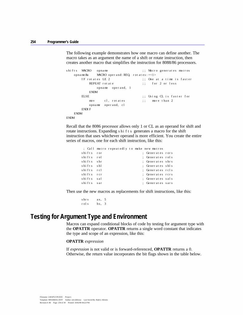
254 Programmer’s Guide
Filename: LMAPGC09.DOC Project: Template: MSGRIDA1.DOT Author: rick debroux Last Saved By: Ruth L Silverio Revision #: 86 Page: 254 of 30 Printed: 10/02/00 04:22 PM
The following example demonstrates how one macro can define another. The macro takes as an argument the name of a shift or rotate instruction, then creates another macro that simplifies the instruction for 8088/86 processors.
shifts MACRO opname ;; Macro generates macros opname&s MACRO operand:REQ, rotates:=<1> IF rotates LE 2 ;; One at a time is faster REPEAT rotate ;; for 2 or less opname operand, 1 ENDM ELSE ;; Using CL is faster for mov cl, rotates ;; more than 2 opname operand, cl ENDIF ENDM ENDM
Recall that the 8086 processor allows only 1 or CL as an operand for shift and rotate instructions. Expanding shifts generates a macro for the shift instruction that uses whichever operand is more efficient. You create the entire series of macros, one for each shift instruction, like this:
; Call macro repeatedly to make new macros shifts ror ; Generates rors shifts rol ; Generates rols shifts shr ; Generates shrs shifts shl ; Generates shls shifts rcl ; Generates rcls shifts rcr ; Generates rcrs shifts sal ; Generates sals shifts sar ; Generates sars
Then use the new macros as replacements for shift instructions, like this:
shrs ax, 5 rols bx, 3
Testing for Argument Type and Environment Macros can expand conditional blocks of code by testing for argument type with the OPATTR operator. OPATTR returns a single word constant that indicates the type and scope of an expression, like this:
OPATTR expression
If expression is not valid or is forward-referenced, OPATTR returns a 0. Otherwise, the return value incorporates the bit flags shown in the table below.
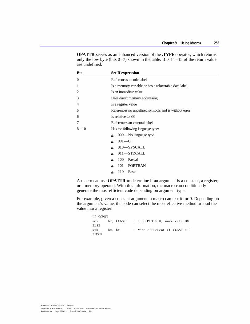
Chapter 9 Using Macros 255
Filename: LMAPGC09.DOC Project: Template: MSGRIDA1.DOT Author: rick debroux Last Saved By: Ruth L Silverio Revision #: 86 Page: 255 of 31 Printed: 10/02/00 04:22 PM
OPATTR serves as an enhanced version of the .TYPE operator, which returns only the low byte (bits 0 – 7) shown in the table. Bits 11 – 15 of the return value are undefined.
Bit Set If expression
0 References a code label 1 Is a memory variable or has a relocatable data label 2 Is an immediate value 3 Uses direct memory addressing 4 Is a register value 5 References no undefined symbols and is without error 6 Is relative to SS 7 References an external label 8 – 10 Has the following language type:
u 000 — No language type u 001 — C u 010 — SYSCALL u 011 — STDCALL u 100 — Pascal u 101 — FORTRAN u 110 — Basic
A macro can use OPATTR to determine if an argument is a constant, a register, or a memory operand. With this information, the macro can conditionally generate the most efficient code depending on argument type.
For example, given a constant argument, a macro can test it for 0. Depending on the argument’s value, the code can select the most effective method to load the value into a register:
IF CONST mov bx, CONST ; If CONST > 0, move into BX ELSE sub bx, bx ; More efficient if CONST = 0 ENDIF
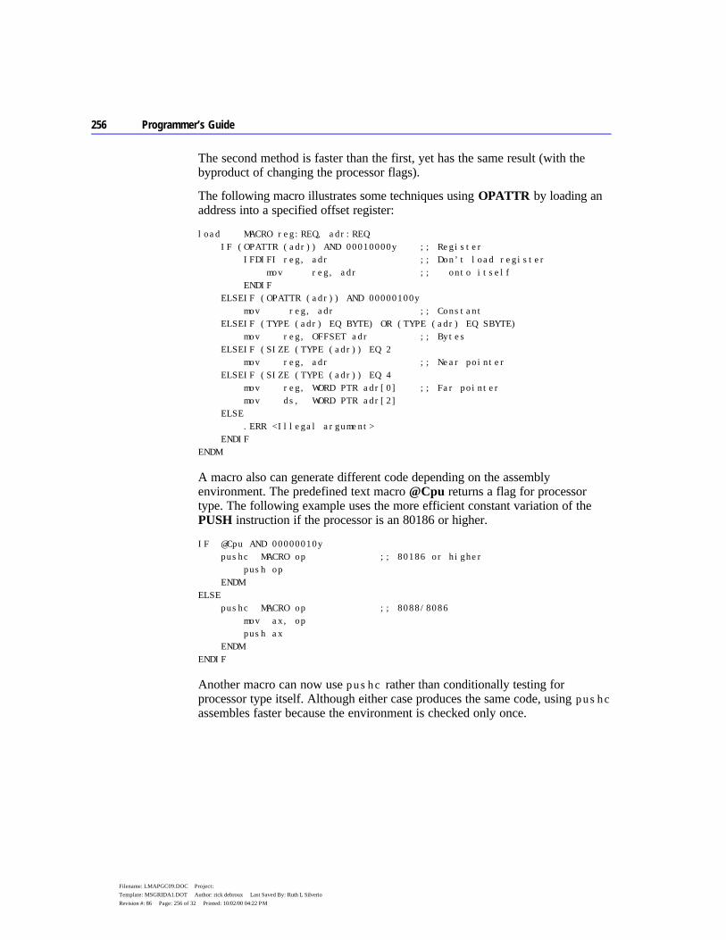
256 Programmer’s Guide
Filename: LMAPGC09.DOC Project: Template: MSGRIDA1.DOT Author: rick debroux Last Saved By: Ruth L Silverio Revision #: 86 Page: 256 of 32 Printed: 10/02/00 04:22 PM
The second method is faster than the first, yet has the same result (with the byproduct of changing the processor flags).
The following macro illustrates some techniques using OPATTR by loading an address into a specified offset register:
load MACRO reg:REQ, adr:REQ IF (OPATTR (adr)) AND 00010000y ;; Register IFDIFI reg, adr ;; Don’t load register mov reg, adr ;; onto itself ENDIF ELSEIF (OPATTR (adr)) AND 00000100y mov reg, adr ;; Constant ELSEIF (TYPE (adr) EQ BYTE) OR (TYPE (adr) EQ SBYTE) mov reg, OFFSET adr ;; Bytes ELSEIF (SIZE (TYPE (adr)) EQ 2 mov reg, adr ;; Near pointer ELSEIF (SIZE (TYPE (adr)) EQ 4 mov reg, WORD PTR adr[0] ;; Far pointer mov ds, WORD PTR adr[2] ELSE .ERR <Illegal argument> ENDIF ENDM
A macro also can generate different code depending on the assembly environment. The predefined text macro @Cpu returns a flag for processor type. The following example uses the more efficient constant variation of the PUSH instruction if the processor is an 80186 or higher.
IF @Cpu AND 00000010y pushc MACRO op ;; 80186 or higher push op ENDM ELSE pushc MACRO op ;; 8088/8086 mov ax, op push ax ENDM ENDIF
Another macro can now use pushc rather than conditionally testing for processor type itself. Although either case produces the same code, using pushc assembles faster because the environment is checked only once.
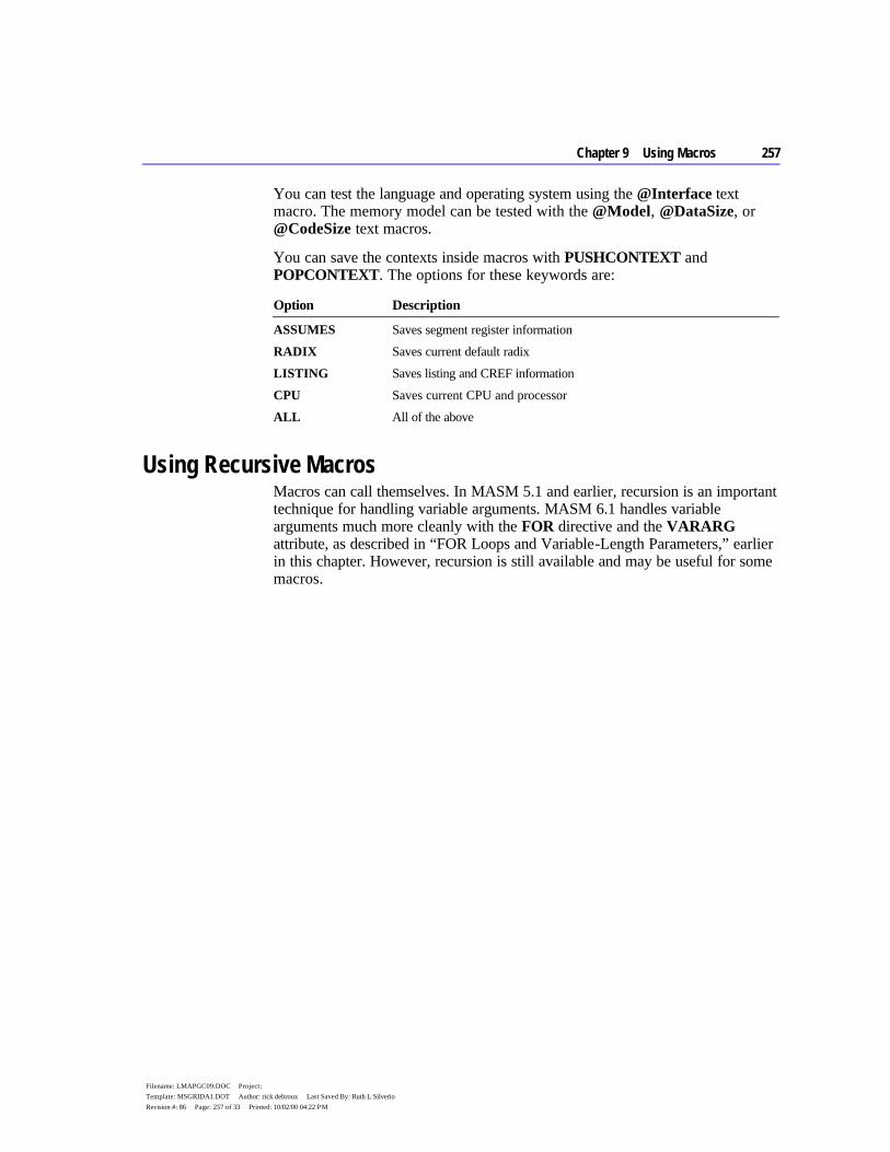
Chapter 9 Using Macros 257
Filename: LMAPGC09.DOC Project: Template: MSGRIDA1.DOT Author: rick debroux Last Saved By: Ruth L Silverio Revision #: 86 Page: 257 of 33 Printed: 10/02/00 04:22 PM
You can test the language and operating system using the @Interface text macro. The memory model can be tested with the @Model, @DataSize, or @CodeSize text macros.
You can save the contexts inside macros with PUSHCONTEXT and POPCONTEXT. The options for these keywords are:
Option Description
ASSUMES Saves segment register information RADIX Saves current default radix LISTING Saves listing and CREF information CPU Saves current CPU and processor ALL All of the above
Using Recursive Macros Macros can call themselves. In MASM 5.1 and earlier, recursion is an important technique for handling variable arguments. MASM 6.1 handles variable arguments much more cleanly with the FOR directive and the VARARG attribute, as described in “FOR Loops and Variable-Length Parameters,” earlier in this chapter. However, recursion is still available and may be useful for some macros.

256 Programmer’s Guide
Filename: LMAPGC09.DOC Project: Template: MSGRIDA1.DOT Author: rick debroux Last Saved By: Ruth L Silverio Revision #: 86 Page: 256 of 34 Printed: 10/02/00 04:22 PM

257
Filename: LMAPGC10.DOC Project: Template: MSGRIDA1.DOT Author: Mike Eddy Last Saved By: Ruth L Silverio Revision #: 62 Page: 257 of 1 Printed: 10/02/00 04:22 PM
C H A P T E R 1 0
The Windows operating system relies heavily on service routines and data contained in special libraries called “dynamic-link libraries,” or DLLs for short. Most of what Windows comprises, from the collections of screen fonts to the routines that handle the graphical interface, is provided by DLLs. MASM 6.1 contains tools that you can use to write DLLs in assembly language. This chapter shows you how.
DLLs do not run under MS-DOS. The information in this chapter applies only to Windows, drawing in part on the chapter “Writing a Module-Definition File” in Environment and Tools. The acronym API, which appears throughout this chapter, refers to the application programming interface that Windows provides for programs. For documentation of API functions, see the Programmer’s Reference, Volume 2 of the Windows Software Development Kit (SDK).
The first section of this chapter gives an overview of DLLs and their similarities to normal libraries. The next section explores the parts of a DLL and the rules you must follow to create one. The third section applies this information to an example DLL.
Overview of DLLs A dynamic-link library is similar to a normal run-time library. Both types of libraries contain a collection of compiled procedures, which serve one or more calling modules. To link a normal library, the linker copies the required functions from the library file (which usually has a .LIB extension) and combines them with other modules to form an executable program in .EXE format. This process is called static linking.
In dynamic linking, the library functions are not copied to an .EXE file. Instead, they reside in a separate file in executable form, ready to serve any calling program, called a “client.” When the first client requires the library, Windows takes care of loading the functions into memory and establishing linkage. If
Writing a Dynamic-Link Library For Windows

258 Programmer’s Guide
Filename: LMAPGC10.DOC Project: Template: MSGRIDA1.DOT Author: Mike Eddy Last Saved By: Ruth L Silverio Revision #: 62 Page: 258 of 2 Printed: 10/02/00 04:22 PM
subsequent clients also need the library, Windows dynamically links them with the proper library functions already in memory.
Loading a DLL How Windows loads a DLL affects the client rather than the DLL itself. Accordingly, this section focuses on how to set up a client program to use a DLL. Since the client can itself be a DLL, this is information a DLL programmer should know. However, MASM 6.1 does not provide all the tools required to create a stand-alone program for Windows. To create such a program, called an “application,” you must use tools in the Windows SDK.
Windows provides two methods for loading a dynamic-link library into memory:
Method Description
Implicit loading Windows loads the DLL along with the first client program and links it before the client begins execution.
Explicit loading Windows does not load the DLL until the first client explicitly requests it during execution.
When you write a DLL, you do not need to know beforehand which of the two methods will be used to load the library. The loading method is determined by how the client is written, not the DLL.
Implicit Loading The implicit method of loading a DLL offers the advantage of simplicity. The client requires no extra programming effort and can call the library functions as if they were normal run-time functions. However, implicit loading carries two constraints:
u The name of the library file must have a .DLL extension. u You must either list all DLL functions the client calls in the IMPORTS
section of the client’s module-definition file, or link the client with an import library.
An import library contains no executable code. It consists of only the names and locations of exported functions in a DLL. The linker uses the locations in the import library to resolve references to DLL functions in the client and to build an executable header. For example, the file LIBW.LIB provided with MASM 6.1 is the import library for the DLL files that contain the Windows API functions.
The IMPLIB utility described in Environment and Tools creates an import library. Run IMPLIB from the MS-DOS command line like this:
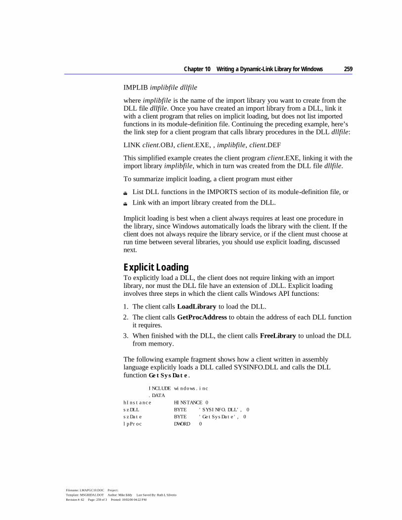
Chapter 10 Writing a Dynamic-Link Library for Windows 259
Filename: LMAPGC10.DOC Project: Template: MSGRIDA1.DOT Author: Mike Eddy Last Saved By: Ruth L Silverio Revision #: 62 Page: 259 of 3 Printed: 10/02/00 04:22 PM
IMPLIB implibfile dllfile
where implibfile is the name of the import library you want to create from the DLL file dllfile. Once you have created an import library from a DLL, link it with a client program that relies on implicit loading, but does not list imported functions in its module-definition file. Continuing the preceding example, here’s the link step for a client program that calls library procedures in the DLL dllfile:
LINK client.OBJ, client.EXE, , implibfile, client.DEF
This simplified example creates the client program client.EXE, linking it with the import library implibfile, which in turn was created from the DLL file dllfile.
To summarize implicit loading, a client program must either
u List DLL functions in the IMPORTS section of its module-definition file, or u Link with an import library created from the DLL.
Implicit loading is best when a client always requires at least one procedure in the library, since Windows automatically loads the library with the client. If the client does not always require the library service, or if the client must choose at run time between several libraries, you should use explicit loading, discussed next.
Explicit Loading To explicitly load a DLL, the client does not require linking with an import library, nor must the DLL file have an extension of .DLL. Explicit loading involves three steps in which the client calls Windows API functions:
1. The client calls LoadLibrary to load the DLL. 2. The client calls GetProcAddress to obtain the address of each DLL function
it requires. 3. When finished with the DLL, the client calls FreeLibrary to unload the DLL
from memory.
The following example fragment shows how a client written in assembly language explicitly loads a DLL called SYSINFO.DLL and calls the DLL function GetSysDate.
INCLUDE windows.inc .DATA hInstance HINSTANCE 0 szDLL BYTE 'SYSINFO.DLL', 0 szDate BYTE 'GetSysDate', 0 lpProc DWORD 0

260 Programmer’s Guide
Filename: LMAPGC10.DOC Project: Template: MSGRIDA1.DOT Author: Mike Eddy Last Saved By: Ruth L Silverio Revision #: 62 Page: 260 of 4 Printed: 10/02/00 04:22 PM
.CODE . . . INVOKE LoadLibrary, ADDR szDLL ; Load SYSINFO.DLL mov hInstance, ax ; Save instance count INVOKE GetProcAddress, ax, ADDR szDate ; Get and save mov lpProc, ax ; far address of mov lpProc[2], dx ; GetSysDate call lpProc ; Call GetSysDate . . . INVOKE FreeLibrary, hInstance ; Unload SYSINFO.DLL
For simplicity, the above example contains no error-checking code. An actual program should check all values returned from the API functions.
The explicit method of loading a DLL requires more programming effort in the client program. However, the method allows the client to control which (if any) dynamic-link libraries to load at run time.
Searching for a DLL File To load a DLL, whether implicitly or explicitly, Windows searches for the DLL file in the following directories in the order shown:
1. The current directory 2. The Windows directory, which contains WIN.COM 3. The Windows system directory, which contains system files such as
GDI.EXE 4. The directory where the client program resides (except Windows 3.0 and
earlier) 5. Directories listed in the PATH environment string 6. Directories mapped in a network
If Windows does not locate the DLL in any of these directories, it prompts the user with a message box.
Building a DLL A DLL has additional programming requirements beyond those for a normal run-time library. This section describes the requirements pertaining to the library’s code, data, and stack. It also discusses the effects of the library’s extension name.

Chapter 10 Writing a Dynamic-Link Library for Windows 261
Filename: LMAPGC10.DOC Project: Template: MSGRIDA1.DOT Author: Mike Eddy Last Saved By: Ruth L Silverio Revision #: 62 Page: 261 of 5 Printed: 10/02/00 04:22 PM
DLL Code The code in a DLL consists of exported and nonexported functions. Exported functions, listed in the EXPORTS section of the module-definition file, are public routines serving clients. Nonexported functions provide private, internal support for the exported procedures. They are not visible to a client.
Under Windows, an exported library routine must appear to the caller as a far procedure. Your DLL routines can use any calling convention you wish, provided the caller assumes the same convention. You can think of dynamic-link code as code for a normal run-time library with the following additions:
u An entry procedure u A termination procedure u Special prologue and epilogue code
Entry Procedure A DLL, like any Windows-based program, must have an entry procedure. Windows calls the entry procedure only once when it first loads the DLL, passing the following information in registers:
u DS contains the library’s data segment address. u DI holds the library’s instance handle. u CX holds the library’s heap size in bytes.
Windows API functions destroy all registers except DI, SI, BP, DS, and the stack pointer. To preserve the contents of other registers, your program must save the registers before an API call and restore them afterwards.
This information corresponds to the data provided to an application. Since a DLL has only one occurrence in memory, called an “instance,” the value in DI is not usually important. However, a DLL can use its instance handle to obtain resources from its own executable file.
The entry procedure does not need to record the address of the data segment. Windows automatically ensures that each exported routine in the DLL has access to the library’s data segment, as explained in “Prologue and Epilogue Code,” on page 264.
The heap size contained in CX reflects the value provided in the HEAPSIZE statement of the module-definition file. You need not make an accurate guess in the HEAPSIZE statement about the library’s heap requirements, provided you specify a moveable data segment. With a moveable segment, Windows automatically allocates more heap when needed. However, Windows can
Note
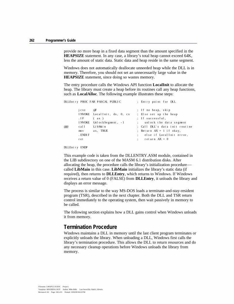
262 Programmer’s Guide
Filename: LMAPGC10.DOC Project: Template: MSGRIDA1.DOT Author: Mike Eddy Last Saved By: Ruth L Silverio Revision #: 62 Page: 262 of 6 Printed: 10/02/00 04:22 PM
provide no more heap in a fixed data segment than the amount specified in the HEAPSIZE statement. In any case, a library’s total heap cannot exceed 64K, less the amount of static data. Static data and heap reside in the same segment.
Windows does not automatically deallocate unneeded heap while the DLL is in memory. Therefore, you should not set an unnecessarily large value in the HEAPSIZE statement, since doing so wastes memory.
The entry procedure calls the Windows API function LocalInit to allocate the heap. The library must create a heap before its routines call any heap functions, such as LocalAlloc. The following example illustrates these steps:
DLLEntry PROC FAR PASCAL PUBLIC ; Entry point for DLL jcxz @F ; If no heap, skip INVOKE LocalInit, ds, 0, cx ; Else set up the heap .IF ( ax ) ; If successful, INVOKE UnlockSegment, -1 ; unlock the data segment @@: call LibMain ; Call DLL's data init routine mov ax, TRUE ; Return AX = 1 if okay, .ENDIF ; else if LocalInit error, ret ; return AX = 0 DLLEntry ENDP
This example code is taken from the DLLENTRY.ASM module, contained in the LIB subdirectory on one of the MASM 6.1 distribution disks. After allocating the heap, the procedure calls the library’s initialization procedure — called LibMain in this case. LibMain initializes the library’s static data (if required), then returns to DLLEntry, which returns to Windows. If Windows receives a return value of 0 (FALSE) from DLLEntry, it unloads the library and displays an error message.
The process is similar to the way MS-DOS loads a terminate-and-stay-resident program (TSR), described in the next chapter. Both the DLL and TSR return control immediately to the operating system, then wait passively in memory to be called.
The following section explains how a DLL gains control when Windows unloads it from memory.
Termination Procedure Windows maintains a DLL in memory until the last client program terminates or explicitly unloads the library. When unloading a DLL, Windows first calls the library’s termination procedure. This allows the DLL to return resources and do any necessary cleanup operations before Windows unloads the library from memory.

Chapter 10 Writing a Dynamic-Link Library for Windows 263
Filename: LMAPGC10.DOC Project: Template: MSGRIDA1.DOT Author: Mike Eddy Last Saved By: Ruth L Silverio Revision #: 62 Page: 263 of 7 Printed: 10/02/00 04:22 PM
Libraries that have registered window procedures with RegisterClass need not call UnregisterClass to remove the class registration. Windows does this automatically when it unloads the library.
You must name the library’s termination procedure WEP (for Windows Exit Procedure) and list it in the EXPORTS section of the library’s module-definition file. To ensure immediate operation, provide an ordinal number and use the RESIDENTNAME keyword, as described in the chapter “Creating Module-Definition Files” in Environment and Tools. This keeps the name “WEP” in the Windows-resident name table at all times.
Besides its name, the code for WEP should also remain constantly in memory. To ensure this, place WEP in its own code segment and set the segment’s attributes as PRELOAD FIXED in the SEGMENTS statement of the module-definition file. Thus, your DLL code should use a memory model that allows multiple code segments, such as medium model. Since a termination procedure is usually short, keeping it resident in memory does not burden the operating system.
The termination procedure accepts a single parameter, which can have one of two values. These values are assigned to the following symbolic constants in the WINDOWS.INC file located in the LIB subdirectory:
u WEP_SYSTEM_EXIT (value 1) indicates Windows is shutting down. u WEP_FREE_DLL (value 0) indicates the library’s last client has terminated or
has called FreeLibrary, and Windows is unloading the DLL.
The following fragment provides an outline for a typical termination procedure:
WEP PROC FAR PASCAL EXPORT wExitCode:WORD Prolog ; Prologue macro, .IF wExitCode == WEP_FREE_DLL ; discussed below . ; Get ready to . ; unload . ELSEIF wExitCode == WEP_SYSTEM_EXIT . ; Windows is . ; shutting down . . ENDIF ; If neither value, ; take no action mov ax, TRUE ; Always return AX = 1 Epilog ; Epilogue code, ret ; discussed below WEP ENDP
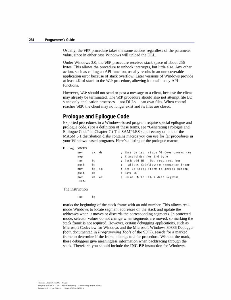
264 Programmer’s Guide
Filename: LMAPGC10.DOC Project: Template: MSGRIDA1.DOT Author: Mike Eddy Last Saved By: Ruth L Silverio Revision #: 62 Page: 264 of 8 Printed: 10/02/00 04:22 PM
Usually, the WEP procedure takes the same actions regardless of the parameter value, since in either case Windows will unload the DLL.
Under Windows 3.0, the WEP procedure receives stack space of about 256 bytes. This allows the procedure to unhook interrupts, but little else. Any other action, such as calling an API function, usually results in an unrecoverable application error because of stack overflow. Later versions of Windows provide at least 4K of stack to the WEP procedure, allowing it to call many API functions.
However, WEP should not send or post a message to a client, because the client may already be terminated. The WEP procedure should also not attempt file I/O, since only application processes — not DLLs — can own files. When control reaches WEP, the client may no longer exist and its files are closed.
Prologue and Epilogue Code Exported procedures in a Windows-based program require special epilogue and prologue code. (For a definition of these terms, see “Generating Prologue and Epilogue Code” in Chapter 7.) The SAMPLES subdirectory on one of the MASM 6.1 distribution disks contains macros you can use for far procedures in your Windows-based programs. Here’s a listing of the prologue macro:
Prolog MACRO mov ax, ds ; Must be 1st, since Windows overwrites nop ; Placeholder for 3rd byte inc bp ; Push odd BP. Not required, but push bp ; allows CodeView to recognize frame mov bp, sp ; Set up stack frame to access params push ds ; Save DS mov ds, ax ; Point DS to DLL's data segment ENDM
The instruction
inc bp
marks the beginning of the stack frame with an odd number. This allows real-mode Windows to locate segment addresses on the stack and update the addresses when it moves or discards the corresponding segments. In protected mode, selector values do not change when segments are moved, so marking the stack frame is not required. However, certain debugging applications, such as Microsoft Codeview for Windows and the Microsoft Windows 80386 Debugger (both documented in Programming Tools of the SDK), search for a marked frame to determine if the frame belongs to a far procedure. Without the mark, these debuggers give meaningless information when backtracing through the stack. Therefore, you should include the INC BP instruction for Windows-
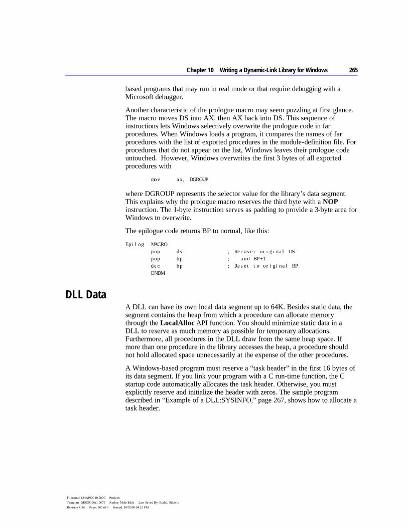
Chapter 10 Writing a Dynamic-Link Library for Windows 265
Filename: LMAPGC10.DOC Project: Template: MSGRIDA1.DOT Author: Mike Eddy Last Saved By: Ruth L Silverio Revision #: 62 Page: 265 of 9 Printed: 10/02/00 04:22 PM
based programs that may run in real mode or that require debugging with a Microsoft debugger.
Another characteristic of the prologue macro may seem puzzling at first glance. The macro moves DS into AX, then AX back into DS. This sequence of instructions lets Windows selectively overwrite the prologue code in far procedures. When Windows loads a program, it compares the names of far procedures with the list of exported procedures in the module-definition file. For procedures that do not appear on the list, Windows leaves their prologue code untouched. However, Windows overwrites the first 3 bytes of all exported procedures with
mov ax, DGROUP
where DGROUP represents the selector value for the library’s data segment. This explains why the prologue macro reserves the third byte with a NOP instruction. The 1-byte instruction serves as padding to provide a 3-byte area for Windows to overwrite.
The epilogue code returns BP to normal, like this:
Epilog MACRO pop ds ; Recover original DS pop bp ; and BP+1 dec bp ; Reset to original BP ENDM
DLL Data A DLL can have its own local data segment up to 64K. Besides static data, the segment contains the heap from which a procedure can allocate memory through the LocalAlloc API function. You should minimize static data in a DLL to reserve as much memory as possible for temporary allocations. Furthermore, all procedures in the DLL draw from the same heap space. If more than one procedure in the library accesses the heap, a procedure should not hold allocated space unnecessarily at the expense of the other procedures.
A Windows-based program must reserve a “task header” in the first 16 bytes of its data segment. If you link your program with a C run-time function, the C startup code automatically allocates the task header. Otherwise, you must explicitly reserve and initialize the header with zeros. The sample program described in “Example of a DLL:SYSINFO,” page 267, shows how to allocate a task header.
266 Programmer’s Guide
Filename: LMAPGC10.DOC Project: Template: MSGRIDA1.DOT Author: Mike Eddy Last Saved By: Ruth L Silverio Revision #: 62 Page: 266 of 10 Printed: 10/02/00 04:22 PM
DLL Stack A DLL does not declare a stack segment and does not allocate stack space. A client program calls a library’s exported procedure through a simple far call, and the stack does not change. The procedure is, in effect, part of the calling program, and therefore uses the caller’s stack.
This simple arrangement differs from that used in small and medium models, in which many C run-time functions accept near pointers as arguments. Such functions assume the pointer is relative to the current data segment. In applications, the call works even if the argument points to a local variable on the stack, since DS and SS contain the same segment address.
However, in a DLL, DS and SS point to different segments. Under small and medium models, a library procedure must always pass pointers to static variables located in the data segment, not to local variables on the stack.
When you write a DLL, include the FARSTACK keyword with the .MODEL directive, like this:
.MODEL small, pascal, farstack
This informs the assembler that SS points to a segment other than DGROUP. With full segment definitions, also add the line:
ASSUME DS:DGROUP, SS:NOTHING
DLL Extension Names You can name an explicitly-loaded DLL file with any extension. The many files in your Windows directory with extensions such as .DRV and .FON are almost certainly DLLs. Many DLLs have an .EXE extension, though they are not true executable files.
A library with an .EXE extension should always include stub code, specified by the STUB statement in the module-definition file. The stub code activates when run under MS-DOS, usually displaying a message to inform the user that the program requires Windows. Without the stub code, the system hangs if a user attempts to run a DLL with an .EXE extension.
Do not name a DLL with a .COM extension, since MS-DOS will give control to the first byte of the program header. The header does not contain executable instructions, and the system will hang even if the DLL has stub code.
Summary Following is a summary of the previous information in this chapter.

Chapter 10 Writing a Dynamic-Link Library for Windows 267
Filename: LMAPGC10.DOC Project: Template: MSGRIDA1.DOT Author: Mike Eddy Last Saved By: Ruth L Silverio Revision #: 62 Page: 267 of 11 Printed: 10/02/00 04:22 PM
u A dynamic-link library has only one instance — that is, it can load only once during a Windows session.
u A single DLL can service calls from many client programs. Windows takes care of linkage between the DLL and each client.
u Windows loads a DLL either implicitly (along with the first client) or explicitly (when the first client calls LoadLibrary). It unloads the DLL when the last client either terminates or calls FreeLibrary.
u A client calls a DLL routine as a simple far procedure. The routine can use any calling convention.
u Windows ensures that the first instruction in a DLL procedure moves the address of the library’s data segment into AX. You must provide the proper prologue code to allow space for this 3-byte instruction and to copy AX to DS.
u All procedures in a DLL have access to a single common data segment. The segment contains both static variables and heap space, and cannot exceed 64K.
u A DLL procedure uses the caller’s stack. u All exported procedures in a DLL must appear in the EXPORTS list in the
library’s module-definition file.
Example of a DLL: SYSINFO Like any library, a DLL should be as small and fast as possible — a good argument for writing it in assembly language. This section describes an example library called SYSINFO, written entirely in assembly language. The following text applies previous information in this chapter to an actual DLL.
SYSINFO contains three callable procedures. The acronym ASCIIZ refers to a string of ASCII characters terminated with a zero. The callable procedures are:
Procedure Description
GetSysTime Returns a far pointer to a 12-byte ASCIIZ string containing the current time in hh:mm:ss format.
GetSysDate Returns a far pointer to an ASCIIZ string containing the current date in any of six languages.
GetSysInfo Returns a far pointer to a structure containing the following system data: u ASCIIZ string of Windows version u ASCIIZ string of MS-DOS version u Current keyboard status u Current video mode
268 Programmer’s Guide
Filename: LMAPGC10.DOC Project: Template: MSGRIDA1.DOT Author: Mike Eddy Last Saved By: Ruth L Silverio Revision #: 62 Page: 268 of 12 Printed: 10/02/00 04:22 PM
u Math coprocessor flag u Processor type u ASCIIZ string of ROM-BIOS release date
To see SYSINFO in action, follow the steps below. The file SYSDATA.EXE resides in the SAMPLES\WINDLL subdirectory of MASM if you requested example files when installing MASM. Otherwise, you must first install the file with the MASM 6.1 SETUP utility.
u Create SYSINFO.DLL as described in the following section and place it in the SAMPLES\WINDLL subdirectory for MASM 6.1.
u From the Windows File Manager, make the SAMPLES\WINDLL subdirectory the current directory.
u In the Program Manager, choose Run from the File menu and type SYSDATA to run the example program SYSDATA.EXE. This program calls the routines in SYSINFO.DLL and displays the returned data.
Entry Routine for SYSINFO SYSINFO links with the DLLENTRY module, which serves as the library’s entry point when Windows first loads the program. For a listing and description of DLLENTRY.ASM, see the previous section, “Entry Procedure.”
DLLENTRY replaces the LIBENTRY module provided with the Windows SDK, but unlocks the data segment after calling the API function InitTask. LIBENTRY does not unlock the segment. DLLENTRY saves some space over LIBENTRY, because it does not pass any arguments to LibMain.
The LibMain procedure handles the library’s initialization tasks. You can name the procedure whatever you want, provided you make the same change in
DLLENTRY.ASM and reassemble both modules. You can even combine DLLENTRY with LibMain to form one procedure, like this:
Chapter 10 Writing a Dynamic-Link Library for Windows 269
Filename: LMAPGC10.DOC Project: Template: MSGRIDA1.DOT Author: Mike Eddy Last Saved By: Ruth L Silverio Revision #: 62 Page: 269 of 13 Printed: 10/02/00 04:22 PM
DLLInit PROC FAR PASCAL PUBLIC ; Entry point for DLL jcxz @F ; If no heap, skip INVOKE LocalInit, ds, 0, cx ; Else set up the heap .IF ( ax ) ; If successful, INVOKE UnlockSegment, -1 ; unlock the data segment @@: . ; Initialize DLL data. This . ; replaces the call to the . ; LibMain procedure. mov ax, TRUE ; Return AX = 1 if okay, .ENDIF ; else if LocalInit error, ret ; return AX = 0 DLLInit ENDP END DLLInit
Whatever you call your combined procedure (DLLInit in the preceding example), place the name on the END statement as shown. This identifies the procedure as the one that first executes when Windows loads the DLL.
SYSINFO accommodates several international languages. Currently, SYSINFO recognizes English, French, Spanish, German, Italian, and Swedish, but you can easily extend the code to include other languages. LibMain calls GetProfileString to determine the current language, then initializes the variable indx accordingly. The variable indirectly points to an array of strings containing days and months in different languages. The GetSysDate procedure uses these strings to create a full date in the correct language.
Static Data SYSINFO stores the strings in its static data segment. This data remains in memory along with the library’s code. All procedures have equal access to the data segment.
Because the library does not call any C run-time functions, it explicitly allocates the low paragraph of the data segment with the variable TaskHead. This 16-byte area serves as the required Windows task header, described in “DLL Data,” earlier in this chapter.
Module-Definition File The library’s module-definition file, named SYSINFO.DEF, looks like this:
270 Programmer’s Guide
Filename: LMAPGC10.DOC Project: Template: MSGRIDA1.DOT Author: Mike Eddy Last Saved By: Ruth L Silverio Revision #: 62 Page: 270 of 14 Printed: 10/02/00 04:22 PM
LIBRARY SYSINFO DESCRIPTION 'Sample assembly-language DLL' EXETYPE WINDOWS CODE PRELOAD MOVEABLE DISCARDABLE DATA PRELOAD MOVEABLE SINGLE SEGMENTS CODE2 PRELOAD FIXED EXPORTS WEP @1 RESIDENTNAME GetSysTime @2 GetSysDate @3 GetSysInfo @4
Note the following points about the module-definition file:
u The LIBRARY statement identifies SYSINFO as a dynamic-link library. u SYSINFO places its termination procedure WEP in a separate code segment,
called CODE2, which the SEGMENTS statement declares as FIXED. This keeps the WEP routine fixed in memory, while all other code remains moveable.
u The EXPORTS section lists all procedures the library exports, including WEP. u None of the library’s procedures require heap space, so SYSINFO.DEF
includes no HEAPSIZE statement.
Assembling and Linking SYSINFO The following listing shows the description file for SYSINFO:
sysinfo.obj: sysinfo.asm dll.inc ML /c /W3 sysinfo.asm dllentry.obj: dllentry.asm dll.inc. ML /c /W3 dllentry.asm sysinfo.dll: dllentry.obj sysinfo.obj LINK dllentry sysinfo, sysinfo.dll,, libw.lib mnocrtdw.lib, sysinfo.def
To create SYSINFO.DLL, run the NMAKE utility described in Chapter 16 of Environments and Tools. Or assemble and link SYSINFO with the three command lines shown in the preceding listing. This does not require running NMAKE.
SYSINFO links with the library modules MNOCRTDW.LIB and LIBW.LIB. The first supplies the required Windows startup code for a medium-model DLL that does not use any C run-time functions. LIBW.LIB is the Windows import library, which contains no executable code. The import library provides linkage information for the Windows API functions referenced in the DLL. Windows establishes the final links when it loads the program.

Chapter 10 Writing a Dynamic-Link Library for Windows 271
Filename: LMAPGC10.DOC Project: Template: MSGRIDA1.DOT Author: Mike Eddy Last Saved By: Ruth L Silverio Revision #: 62 Page: 271 of 15 Printed: 10/02/00 04:22 PM
Expanding SYSINFO SYSINFO is an example of how to write an assembly-language DLL without overwhelming detail. It has plenty of room for expansion and improvements. The following list may give you some ideas:
u To create a heap area for the library, add the line HEAPSIZE value to the module-definition file, where value is an approximate guess for the amount of heap required in bytes. The DLLEntry procedure automatically allocates the indicated amount of heap. Keep the data segment moveable, because Windows then provides more heap space if required by the DLL procedures.
u If you want to add a procedure that calls C run-time functions, you must replace MNOCRTDW.LIB with MDLLCW.LIB, which is supplied with the Windows SDK. The MDLLCW.LIB library contains the run-time functions for medium-model DLLs.
u Each time the GetSysInfo procedure is called, it retrieves the version number of MS-DOS and Windows, gets the processor type, checks for a coprocessor, and reads the ROM-BIOS release date. Since this information does not change throughout a Windows session, it would be handled more efficiently in the LibMain procedure, which executes only once. The code is currently placed in GetSysInfo for the sake of clarity at the expense of efficiency.
u SYSINFO is not a true international program. You can easily add more languages, extending the days and months arrays accordingly. Moreover, for the sake of simplicity, the GetSysDate procedure arranges the date with an American bias. For example, in many parts of the world, the date numeral appears before the month rather than after. If you use SYSINFO in your own applications, you should include code in LibMain to determine the correct date format with additional calls to GetProfileString. You can find more information on how to do this in Chapter 18 of the Microsoft Windows Programmer’s Reference, Volume 1, supplied with the Windows SDK.

272 Programmer’s Guide
Filename: LMAPGC10.DOC Project: Template: MSGRIDA1.DOT Author: Mike Eddy Last Saved By: Ruth L Silverio Revision #: 62 Page: 272 of 16 Printed: 10/02/00 04:22 PM

273
Filename: LMAPGC11.DOC Project: Template: MSGRIDA1.DOT Author: Mike Eddy Last Saved By: Ruth L Silverio Revision #: 66 Page: 273 of 1 Printed: 10/02/00 04:22 PM
C H A P T E R 1 1
Through its memory-management system, MS-DOS allows a program to remain resident in memory after terminating. The resident program can later regain control of the processor to perform tasks such as background printing or “popping up” a calculator on the screen. Such a program is commonly called a TSR, from the terminate-and-stay-resident function it uses to return to MS-DOS.
This chapter explains the techniques of writing memory-resident software. The first two sections present introductory material. Following sections describe important MS-DOS and BIOS interrupts and focus on how to write safe, compatible, memory-resident software. Two example programs illustrate the techniques described in the chapter. The MASM 6.1 disks contain complete source code for the two example TSR programs.
Terminate-and-Stay-Resident Programs MS-DOS maintains a pointer to the beginning of unused memory. Programs load into memory at this position and terminate execution by returning control to MS-DOS. Normally, the pointer remains unchanged, allowing MS-DOS to reuse the same memory when loading other programs.
A terminating program can, however, prevent other programs from loading on top of it. These programs exit to MS-DOS through the terminate-and-stay-resident function, which resets the free-memory pointer to a higher position. This leaves the program resident in a protected block of memory, even though it is no longer running.
Writing Memory-Resident Software
274 Programmer’s Guide
Filename: LMAPGC11.DOC Project: Template: MSGRIDA1.DOT Author: Mike Eddy Last Saved By: Ruth L Silverio Revision #: 66 Page: 274 of 2 Printed: 10/02/00 04:22 PM
The terminate-and-stay-resident function (Function 31h) is one of the MS-DOS services invoked through Interrupt 21h. The following fragment shows how a TSR program terminates through Function 31h and remains resident in a 1000h-byte block of memory:
mov ah, 31h ; Request DOS Function 31h mov al, err ; Set return code mov dx, 100h ; Reserve 100h paragraphs ; (1000h bytes) int 21h ; Terminate-and-stay-resident
In current versions of MS-DOS, Interrupt 27h also provides a terminate-and-stay-resident service. However, Microsoft cannot guarantee future support for Interrupt 27h and does not recommend its use.
Structure of a TSR TSRs consist of two distinct parts that execute at different times. The first part is the installation section, which executes only once, when MS-DOS loads the program. The installation code performs any initialization tasks required by the TSR and then exits through the terminate-and-stay-resident function.
The second part of the TSR, called the resident section, consists of code and data left in memory after termination. Though often identified with the TSR itself, the resident section makes up only part of the entire program.
The TSR’s resident code must be able to regain control of the processor and execute after the program has terminated. Methods of executing a TSR are classified as either passive or active.
Passive TSRs The simplest way to execute a TSR is to transfer control to it explicitly from another program. Because the TSR in this case does not solicit processor control, it is said to be passive. If the calling program can determine the TSR’s memory address, it can grant control via a far jump or call. More commonly, a program activates a passive TSR through a software interrupt. The installation section of the TSR writes the address of its resident code to the proper position in the interrupt vector table (see “MS-DOS Interrupts” in Chapter 7). Any subsequent program can then execute the TSR by calling the interrupt.
Passive TSRs often replace existing software interrupts. For example, a passive TSR might replace Interrupt 10h, the BIOS video service. By intercepting calls that read or write to the screen, the TSR can access the video buffer directly, increasing display speed.
Note
Chapter 11 Writing Memory-Resident Software 275
Filename: LMAPGC11.DOC Project: Template: MSGRIDA1.DOT Author: Mike Eddy Last Saved By: Ruth L Silverio Revision #: 66 Page: 275 of 3 Printed: 10/02/00 04:22 PM
Passive TSRs allow limited access since they can be invoked only from another program. They have the advantage of executing within the context of the calling program, and thus run no risk of interfering with another process. Such a risk does exist with active TSRs.
Active TSRs The second method of executing a TSR involves signaling it through some hardware event, such as a predetermined sequence of keystrokes. This type of TSR is “active” because it must continually search for its startup signal. The advantage of active TSRs lies in their accessibility. They can take control from any running application, execute, and return, all on demand.
An active TSR, however, must not seize processor control blindly. It must contain additional code that determines the proper moment at which to execute. The extra code consists of one or more routines called “interrupt handlers,” described in the following section.
Interrupt Handlers in Active TSRs The memory-resident portion of an active TSR consists of two parts. One part contains the body of the TSR — the code and data that perform the program’s main tasks. The other part contains the TSR’s interrupt handlers.
An interrupt handler is a routine that takes control when a specific interrupt occurs. Although sometimes called an “interrupt service routine,” a TSR’s handler usually does not service the interrupt. Instead, it passes control to the original interrupt routine, which does the actual interrupt servicing. (See the section “Replacing an Interrupt Routine” in Chapter 7 for information on how to write an interrupt handler.)
Collectively, interrupt handlers ensure that a TSR operates compatibly with the rest of the system. Individually, each handler fulfills one or more of the following functions:
u Auditing hardware events that may signal a request for the TSR u Monitoring system status u Determining whether a request for the TSR should be honored, based on
current system status
Auditing Hardware Events for TSR Requests Active TSRs commonly use a special keystroke sequence or the timer as a request signal. A TSR invoked through one of these channels must be equipped with handlers that audit keyboard or timer events.

276 Programmer’s Guide
Filename: LMAPGC11.DOC Project: Template: MSGRIDA1.DOT Author: Mike Eddy Last Saved By: Ruth L Silverio Revision #: 66 Page: 276 of 4 Printed: 10/02/00 04:22 PM
A keyboard handler receives control at every keystroke. It examines each key, searching for the proper signal or “hot key.” Generally, a keyboard handler should not attempt to call the TSR directly when it detects the hot key. If the TSR cannot safely interrupt the current process at that moment, the keyboard handler is forced to exit to allow the process to continue. Since the handler cannot regain control until the next keystroke, the user has to press the hot key repeatedly until the handler can comply with the request.
Instead, the handler should merely set a request flag when it detects a hot-key signal and then exit normally. Examples in the following paragraphs illustrate this technique.
For computers other than MCA (IBM PS/2 and compatible), an active TSR audits keystrokes through a handler for Interrupt 09, the keyboard interrupt:
Keybrd PROC FAR sti ; Interrupts are okay push ax ; Save AX register in al, 60h ; AL = key scan code call CheckHotKey ; Check for hot key .IF carry? ; If hot key pressed, mov cs:TsrRequestFlag, TRUE ; raise flag and . ; set up for exit . .
A TSR running on a PS/2 computer cannot reliably read key scan codes using this method. Instead, the TSR must search for its hot key through a handler for Interrupt 15h (Miscellaneous System Services). The handler determines the current keypress from the AL register when AH equals 4Fh, as shown here:
MiscServ PROC FAR sti ; Interrupts okay .IF ah == 4Fh ; If Keyboard Intercept Service: call CheckHotKey ; Check for hot key .IF carry? ; If hot key pressed, mov cs:TsrRequestFlag, TRUE ; raise flag and . ; set up for exit . .
The example program on page 293 shows how a TSR tests for a PS/2 machine and then sets up a handler for either Interrupt 09 or Interrupt 15h to audit keystrokes.
Setting a request flag in the keyboard handler allows other code, such as the timer handler (Interrupt 08), to recognize a request for the TSR. The timer handler gains control at every timer interrupt, which occurs an average of 18.2 times per second.

Chapter 11 Writing Memory-Resident Software 277
Filename: LMAPGC11.DOC Project: Template: MSGRIDA1.DOT Author: Mike Eddy Last Saved By: Ruth L Silverio Revision #: 66 Page: 277 of 5 Printed: 10/02/00 04:22 PM
The following fragment shows how a timer handler tests the request flag and continually polls until it can safely execute the TSR.
NewTimer PROC FAR . . . cmp TsrRequestFlag, FALSE ; Has TSR been requested? .IF !zero? ; If so, can system be call CheckSystem ; interrupted safely? .IF carry? ; If so, call ActivateTsr ; activate TSR . . .
Monitoring System Status A TSR that uses a hardware device such as the video or disk must not interrupt while the device is active. A TSR monitors a device by handling the device’s interrupt. Each interrupt handler simply sets a flag to indicate the device is in use, and then clears the flag when the interrupt finishes.
The following shows a typical monitor handler:
NewHandler PROC FAR mov cs:ActiveFlag, TRUE ; Set active flag pushf ; Simulate interrupt by ; pushing flags, then call OldHandler ; far-calling original routine mov cs:ActiveFlag, FALSE ; Clear active flag iret ; Return from interrupt NewHandler ENDP
Only hardware used by the TSR requires monitoring. For example, a TSR that performs disk input/output (I/O) must monitor disk use through Interrupt 13h. The disk handler sets an active flag that prevents the TSR from executing during a read or write operation. Otherwise, the TSR’s own I/O would move the disk head. This would cause the suspended disk operation to continue with the head incorrectly positioned when the TSR returned control to the interrupted program.
In the same way, an active TSR that displays to the screen must monitor calls to Interrupt 10h. The Interrupt 10h BIOS routine does not protect critical sections of code that program the video controller. The TSR must therefore ensure it does not interrupt such nonreentrant operations.
The activities of the operating system also affect the system status. With few exceptions, MS-DOS functions are not reentrant and must not be interrupted.
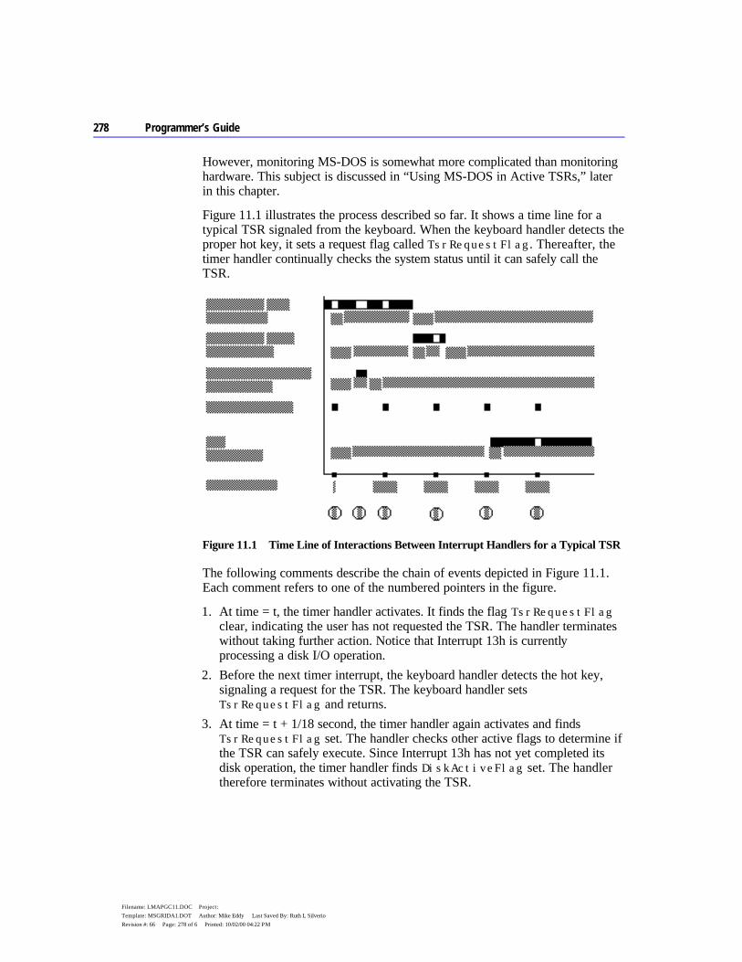
278 Programmer’s Guide
Filename: LMAPGC11.DOC Project: Template: MSGRIDA1.DOT Author: Mike Eddy Last Saved By: Ruth L Silverio Revision #: 66 Page: 278 of 6 Printed: 10/02/00 04:22 PM
However, monitoring MS-DOS is somewhat more complicated than monitoring hardware. This subject is discussed in “Using MS-DOS in Active TSRs,” later in this chapter.
Figure 11.1 illustrates the process described so far. It shows a time line for a typical TSR signaled from the keyboard. When the keyboard handler detects the proper hot key, it sets a request flag called TsrRequestFlag. Thereafter, the timer handler continually checks the system status until it can safely call the TSR.
Figure 11.1 Time Line of Interactions Between Interrupt Handlers for a Typical TSR
The following comments describe the chain of events depicted in Figure 11.1. Each comment refers to one of the numbered pointers in the figure.
1. At time = t, the timer handler activates. It finds the flag TsrRequestFlag clear, indicating the user has not requested the TSR. The handler terminates without taking further action. Notice that Interrupt 13h is currently processing a disk I/O operation.
2. Before the next timer interrupt, the keyboard handler detects the hot key, signaling a request for the TSR. The keyboard handler sets TsrRequestFlag and returns.
3. At time = t + 1/18 second, the timer handler again activates and finds TsrRequestFlag set. The handler checks other active flags to determine if the TSR can safely execute. Since Interrupt 13h has not yet completed its disk operation, the timer handler finds DiskActiveFlag set. The handler therefore terminates without activating the TSR.

Chapter 11 Writing Memory-Resident Software 279
Filename: LMAPGC11.DOC Project: Template: MSGRIDA1.DOT Author: Mike Eddy Last Saved By: Ruth L Silverio Revision #: 66 Page: 279 of 7 Printed: 10/02/00 04:22 PM
4. At time = t + 2/18 second, the timer handler again finds TsrRequestFlag set and repeats its scan of the active flags. DiskActiveFlag is now clear, but in the interim, Interrupt 10h has activated as indicated by the flag VideoActiveFlag. The timer handler accordingly terminates without activating the TSR.
5. At time = t + 3/18 second, the timer handler repeats the process. This time it finds all active flags clear, indicating the TSR can safely execute. The timer handler calls the TSR, which sets its own active flag to ensure it will not interrupt itself if requested again.
6. The timer and other interrupts continue to function normally while the TSR executes.
The timer itself can serve as the startup signal if the TSR executes periodically. Screen clocks that continuously show seconds and minutes are examples of TSRs that use the timer this way. ALARM.ASM, a program described in the next section, shows another example of a timer-driven TSR.
Determining Whether to Invoke the TSR Once a handler receives a request signal for the TSR, it checks the various active flags maintained by the handlers that monitor system status. If any of the flags are set, the handler ignores the request and exits. If the flags are clear, the handler invokes the TSR, usually through a near or far call. Figure 11.1 illustrates how a timer handler detects a request and then periodically scans various active flags until all the flags are clear.
A TSR that changes stacks must not interrupt itself. Otherwise, the second execution would overwrite the stack data belonging to the first. A TSR prevents this by setting its own active flag before executing, as shown in Figure 11.1. A handler must check this flag along with the other active flags when determining whether the TSR can safely execute.
Example of a Simple TSR: ALARM This section presents a simple alarm clock TSR that demonstrates some of the material covered so far. The program accepts an argument from the command line that specifies the alarm setting in military form, such as 1635 for 4:35 P.M. For simplicity, the argument must consist of four digits, including leading zeros. To set the alarm at 7:45 A.M., for example, enter the command:
ALARM 0745
The installation section of the program begins with the Install procedure. Install computes the number of five-second intervals that must elapse before the alarm sounds and stores this number in the word CountDown. The
280 Programmer’s Guide
Filename: LMAPGC11.DOC Project: Template: MSGRIDA1.DOT Author: Mike Eddy Last Saved By: Ruth L Silverio Revision #: 66 Page: 280 of 8 Printed: 10/02/00 04:22 PM
procedure then obtains the vector for Interrupt 08 (timer) through MS-DOS Function 35h and stores it in the far pointer OldTimer. Function 25h replaces the vector with the far address of the new timer handler NewTimer. Once installed, the new timer handler executes at every timer interrupt. These interrupts occur 18.2 times per second or 91 times every five seconds.
Each time it executes, NewTimer subtracts one from a secondary counter called Tick91. By counting 91 timer ticks, Tick91 accurately measures a period of five seconds. When Tick91 reaches zero, it’s reset to 91 and CountDown is decremented by one. When CountDown reaches zero, the alarm sounds.
;* ALARM.ASM - A simple memory-resident program that beeps the speaker ;* at a prearranged time. Can be loaded more than once for multiple ;* alarm settings. During installation, ALARM establishes a handler ;* for the timer interrupt (Interrupt 08). It then terminates through ;* the terminate-and-stay-resident function (Function 31h). After the ;* alarm sounds, the resident portion of the program retires by setting ;* a flag that prevents further processing in the handler. .MODEL tiny ; Create ALARM.COM .STACK .CODE ORG 5Dh ; Location of time argument in PSP, CountDown LABEL WORD ; converted to number of 5-second ; intervals to elapse .STARTUP jmp Install ; Jump over data and resident code ; Data must be in code segment so it won’t be thrown away with Install code. OldTimer DWORD ? ; Address of original timer routine tick_91 BYTE 91 ; Counts 91 clock ticks (5 seconds) TimerActiveFlag BYTE 0 ; Active flag for timer handler ;* NewTimer - Handler routine for timer interrupt (Interrupt 08). ;* Decrements CountDown every 5 seconds. No other action is taken ;* until CountDown reaches 0, at which time the speaker sounds. NewTimer PROC FAR .IF cs:TimerActiveFlag != 0 ; If timer busy or retired, jmp cs:OldTimer ; jump to original timer routine .ENDIF inc cs:TimerActiveFlag ; Set active flag pushf ; Simulate interrupt by pushing flags, call cs:OldTimer ; then far-calling original routine sti ; Enable interrupts push ds ; Preserve DS register push cs ; Point DS to current segment for pop ds ; further memory access dec tick_91 ; Count down for 91 ticks
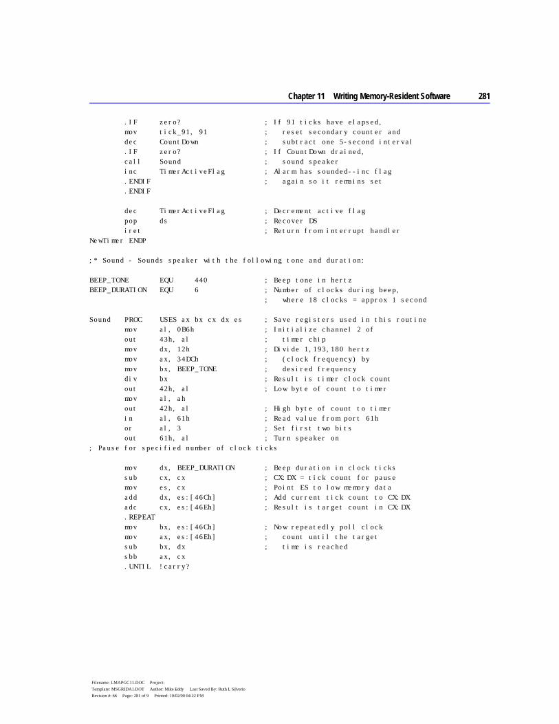
Chapter 11 Writing Memory-Resident Software 281
Filename: LMAPGC11.DOC Project: Template: MSGRIDA1.DOT Author: Mike Eddy Last Saved By: Ruth L Silverio Revision #: 66 Page: 281 of 9 Printed: 10/02/00 04:22 PM
.IF zero? ; If 91 ticks have elapsed, mov tick_91, 91 ; reset secondary counter and dec CountDown ; subtract one 5-second interval .IF zero? ; If CountDown drained, call Sound ; sound speaker inc TimerActiveFlag ; Alarm has sounded--inc flag .ENDIF ; again so it remains set .ENDIF dec TimerActiveFlag ; Decrement active flag pop ds ; Recover DS iret ; Return from interrupt handler NewTimer ENDP ;* Sound - Sounds speaker with the following tone and duration: BEEP_TONE EQU 440 ; Beep tone in hertz BEEP_DURATION EQU 6 ; Number of clocks during beep, ; where 18 clocks = approx 1 second Sound PROC USES ax bx cx dx es ; Save registers used in this routine mov al, 0B6h ; Initialize channel 2 of out 43h, al ; timer chip mov dx, 12h ; Divide 1,193,180 hertz mov ax, 34DCh ; (clock frequency) by mov bx, BEEP_TONE ; desired frequency div bx ; Result is timer clock count out 42h, al ; Low byte of count to timer mov al, ah out 42h, al ; High byte of count to timer in al, 61h ; Read value from port 61h or al, 3 ; Set first two bits out 61h, al ; Turn speaker on ; Pause for specified number of clock ticks mov dx, BEEP_DURATION ; Beep duration in clock ticks sub cx, cx ; CX:DX = tick count for pause mov es, cx ; Point ES to low memory data add dx, es:[46Ch] ; Add current tick count to CX:DX adc cx, es:[46Eh] ; Result is target count in CX:DX .REPEAT mov bx, es:[46Ch] ; Now repeatedly poll clock mov ax, es:[46Eh] ; count until the target sub bx, dx ; time is reached sbb ax, cx .UNTIL !carry?
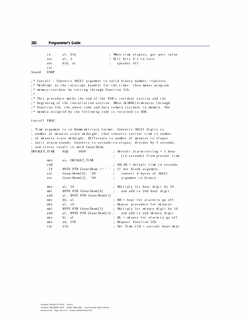
282 Programmer’s Guide
Filename: LMAPGC11.DOC Project: Template: MSGRIDA1.DOT Author: Mike Eddy Last Saved By: Ruth L Silverio Revision #: 66 Page: 282 of 10 Printed: 10/02/00 04:22 PM
in al, 61h ; When time elapses, get port value xor al, 3 ; Kill bits 0-1 to turn out 61h, al ; speaker off ret Sound ENDP ;* Install - Converts ASCII argument to valid binary number, replaces ;* NewTimer as the interrupt handler for the timer, then makes program ;* memory-resident by exiting through Function 31h. ;* ;* This procedure marks the end of the TSR's resident section and the ;* beginning of the installation section. When ALARM terminates through ;* Function 31h, the above code and data remain resident in memory. The ;* memory occupied by the following code is returned to DOS. Install PROC ; Time argument is in hhmm military format. Converts ASCII digits to ; number of minutes since midnight, then converts current time to number ; of minutes since midnight. Difference is number of minutes to elapse ; until alarm sounds. Converts to seconds-to-elapse, divides by 5 seconds, ; and stores result in word CountDown. DEFAULT_TIME EQU 3600 ; Default alarm setting = 1 hour ; (in seconds) from present time mov ax, DEFAULT_TIME cwd ; DX:AX = default time in seconds .IF BYTE PTR CountDown != ' ' ; If not blank argument, xor CountDown[0], '00' ; convert 4 bytes of ASCII xor CountDown[2], '00' ; argument to binary mov al, 10 ; Multiply 1st hour digit by 10 mul BYTE PTR CountDown[0] ; and add to 2nd hour digit add al, BYTE PTR CountDown[1] mov bh, al ; BH = hour for alarm to go off mov al, 10 ; Repeat procedure for minutes mul BYTE PTR CountDown[2] ; Multiply 1st minute digit by 10 add al, BYTE PTR CountDown[3] ; and add to 2nd minute digit mov bl, al ; BL = minute for alarm to go off mov ah, 2Ch ; Request Function 2Ch int 21h ; Get Time (CX = current hour/min)

Chapter 11 Writing Memory-Resident Software 283
Filename: LMAPGC11.DOC Project: Template: MSGRIDA1.DOT Author: Mike Eddy Last Saved By: Ruth L Silverio Revision #: 66 Page: 283 of 11 Printed: 10/02/00 04:22 PM
mov dl, dh sub dh, dh push dx ; Save DX = current seconds mov al, 60 ; Multiply current hour by 60 mul ch ; to convert to minutes sub ch, ch add cx, ax ; Add current minutes to result ; CX = minutes since midnight mov al, 60 ; Multiply alarm hour by 60 mul bh ; to convert to minutes sub bh, bh add ax, bx ; AX = number of minutes since ; midnight for alarm setting sub ax, cx ; AX = time in minutes to elapse ; before alarm sounds .IF carry? ; If alarm time is tomorrow, add ax, 24 * 60 ; add minutes in a day .ENDIF mov bx, 60 mul bx ; DX:AX = minutes-to-elapse-times-60 pop bx ; Recover current seconds sub ax, bx ; DX:AX = seconds to elapse before sbb dx, 0 ; alarm activates .IF carry? ; If negative, mov ax, 5 ; assume 5 seconds cwd .ENDIF .ENDIF mov bx, 5 ; Divide result by 5 seconds div bx ; AX = number of 5-second intervals mov CountDown, ax ; to elapse before alarm sounds mov ax, 3508h ; Request Function 35h int 21h ; Get Vector for timer (Interrupt 08) mov WORD PTR OldTimer[0], bx ; Store address of original mov WORD PTR OldTimer[2], es ; timer interrupt mov ax, 2508h ; Request Function 25h mov dx, OFFSET NewTimer ; DS:DX points to new timer handler int 21h ; Set Vector with address of NewTimer mov dx, OFFSET Install ; DX = bytes in resident section mov cl, 4 shr dx, cl ; Convert to number of paragraphs inc dx ; plus one mov ax, 3100h ; Request Function 31h, error code=0 int 21h ; Terminate-and-stay-resident Install ENDP END
284 Programmer’s Guide
Filename: LMAPGC11.DOC Project: Template: MSGRIDA1.DOT Author: Mike Eddy Last Saved By: Ruth L Silverio Revision #: 66 Page: 284 of 12 Printed: 10/02/00 04:22 PM
Note the following points about ALARM:
u The constant BEEP_TONE specifies the alarm tone. Practical values for the tone range from approximately 100 to 4,000 hertz.
u The Install procedure marks the beginning of the installation section of the program. Execution begins here when ALARM.COM is loaded. A TSR generally places its installation code after the resident section. This allows the terminating TSR to include the installation code with the rest of the memory it returns to MS-DOS. Since the installation section executes only once, the TSR can discard it after becoming resident.
u You can install ALARM any number of times in quick succession, each time with a new alarm setting. The timer handler does not restore the original vector for Interrupt 08 after the alarm sounds. In effect, the multiple installations remain daisy-chained in memory. The address in OldTimer for one installation is the address of NewTimer in the preceding installation.
u Until a system reboot, NewTimer remains in place as the Interrupt 08 handler, even after the alarm sounds. To save unnecessary activity, the byte TimerActiveFlag remains set after the alarm sounds. This forces an immediate jump to the original handler for all subsequent executions of NewTimer.
u NewTimer and Sound alter registers DS, AX, BX, CX, DX, and ES. To preserve the original values in these registers, the procedures first push them onto the stack and then restore the original values before exiting. This ensures that the process interrupted by NewTimer continues with valid registers after NewTimer returns.
u ALARM requires little stack space. It assumes the current stack is adequate and makes no attempt to set up a new one. More sophisticated TSRs, however, should as a matter of course provide their own stacks to ensure adequate stack depth. The example program presented in “Example of an Advanced TSR: SNAP,” later in this chapter, demonstrates this safety measure.
Chapter 11 Writing Memory-Resident Software 285
Filename: LMAPGC11.DOC Project: Template: MSGRIDA1.DOT Author: Mike Eddy Last Saved By: Ruth L Silverio Revision #: 66 Page: 285 of 13 Printed: 10/02/00 04:22 PM
Using MS-DOS in Active TSRs This section explains how to write active TSRs that can safely call MS-DOS functions. The material explores the problems imposed by the nonreentrant nature of MS-DOS and explains how a TSR can resolve those problems. The solution consists of four parts:
u Understanding how MS-DOS uses stacks u Determining when MS-DOS is active u Determining whether a TSR can safely interrupt an active MS-DOS function u Monitoring the Critical Error flag
Understanding MS-DOS Stacks MS-DOS functions set up their own stacks, which makes them nonreentrant. If a TSR interrupts an MS-DOS function and then executes another function that sets up the same stack, the second function will overwrite everything placed on the stack by the first function. The problem occurs when the second function returns and the first is left with unusable stack data. A TSR that calls an MS-DOS function must not interrupt any function that uses the same stack.
MS-DOS versions 2.0 and later use three internal stacks: an I/O stack, a disk stack, and an auxiliary stack. The current stack depends on the MS-DOS function. Functions 01 through 0Ch set up the I/O stack. Functions higher than 0Ch (with few exceptions) use the disk stack, as do Interrupts 25h and 26h. MS-DOS normally uses the auxiliary stack only when it executes Interrupt 24h (Critical Error Handler).
Determining MS-DOS Activity A TSR’s handlers can determine when MS-DOS is active by consulting a 1-byte flag called the InDos flag. Every MS-DOS function sets this flag upon entry and clears it upon termination. During installation, a TSR locates the flag through Function 34h (Get Address of InDos Flag), which returns the address as ES:BX. The installation portion then stores the address so the handlers can later find the flag without again calling Function 34h.
Theoretically, a TSR can wait to execute until the InDos flag is clear, thus sidestepping the entire issue of interrupting MS-DOS. However, several low-order functions — such as Function 0Ah (Get Buffered Keyboard Input) — wait idly for an expected keystroke before they terminate. If a TSR were allowed to execute only after MS-DOS returned, it too would have to wait for the terminating event.

286 Programmer’s Guide
Filename: LMAPGC11.DOC Project: Template: MSGRIDA1.DOT Author: Mike Eddy Last Saved By: Ruth L Silverio Revision #: 66 Page: 286 of 14 Printed: 10/02/00 04:22 PM
The solution lies in determining when the low-order functions 01 through 0Ch are active. MS-DOS provides another service for this purpose: Interrupt 28h, the Idle Interrupt.
Interrupting MS-DOS Functions MS-DOS continually calls Interrupt 28h from the low-order polling functions as they wait for keyboard input. This signal says that MS-DOS is idle and that a TSR may interrupt provided it does not overwrite the I/O stack. Put another way, a TSR can safely interrupt MS-DOS Functions 01 through 0Ch provided it does not call them.
An active TSR that calls MS-DOS must monitor Interrupt 28h with a handler. When the handler gains control, it checks the TSR request flag. If the flag indicates the TSR has been requested and if system hardware is inactive, the handler executes the TSR. Since control must eventually return to the idle MS-DOS function which has stored data on the I/O stack, the TSR in this case must not call any MS-DOS function that also uses the I/O stack. Table 11.1 shows which functions set up the I/O stack for various versions of MS-DOS.
Table 11.1 MS-DOS Internal Stacks
Function
Critical Error flag
MS-DOS 2.x
MS-DOS 3.0
MS-DOS 3.1+
01–0Ch Clear Set
I/O* Aux*
I/O Aux
I/O Aux
33h Clear Set
Disk* Disk
Disk Disk
Caller* Caller
50h–51h Clear Set
I/O Aux
Caller Caller
Caller Caller
59h Clear Set
n/a* n/a
I/O Aux
Disk Disk
5D0Ah Clear Set
n/a n/a
n/a n/a
Disk Disk
62h Clear Set
n/a n/a
Caller Caller
Caller Caller
All others Clear Set
Disk Disk
Disk Disk
Disk Disk
* I/O=I/O stack, Aux = auxiliary stack, Disk = disk stack, Caller = caller’s stack, n/a = function not available.
Chapter 11 Writing Memory-Resident Software 287
Filename: LMAPGC11.DOC Project: Template: MSGRIDA1.DOT Author: Mike Eddy Last Saved By: Ruth L Silverio Revision #: 66 Page: 287 of 15 Printed: 10/02/00 04:22 PM
TSRs that perform tasks of long or indefinite duration should themselves call Interrupt 28h. For example, a TSR that polls for keyboard input should include an INT 28h instruction in the polling loop, as shown here:
poll: int 28h ; Signal idle state mov ah, 1 int 16h ; Key waiting? jnz poll ; If not, repeat polling loop sub ah, ah int 16h ; Otherwise, get key
This courtesy gives other TSRs a chance to execute if the InDos flag happens to be set.
Monitoring the Critical Error Flag MS-DOS sets the Critical Error flag to a nonzero value when it detects a critical error. It then invokes Interrupt 24h (Critical Error Handler) and clears the flag when Interrupt 24h returns. MS-DOS functions higher than 0Ch are illegal during critical error processing. Therefore, a TSR that calls MS-DOS must not execute while the Critical Error flag is set.
MS-DOS versions 3.1 and later locate the Critical Error flag in the byte preceding the InDos flag. A single call to Function 34h (Get Address of InDos Flag) thus effectively returns the addresses of both flags. For earlier versions of MS-DOS or for the compatibility version of MS-DOS in OS/2 1.x, a TSR must call Function 34h and then scan the segment returned in the ES register for one of the two following sequences of instructions:
; Sequence of instructions in DOS Versions 2.0 - 3.0 cmp ss:[CriticalErrorFlag], 0 jne @F int 28h ; Sequence of instructions in DOS compatibility version for OS/2 1.x test [CriticalErrorFlag], 0FFh jnz @F push ss:[ ? ] int 28h
The question mark inside brackets in the preceding PUSH statement indicates that the operand for the PUSH instruction can be any legal operand.
In either version of MS-DOS, the operand field in the first instruction gives the flag’s offset. The value in ES determines the segment address. “Example of an Advanced TSR: SNAP,” later in the chapter, presents a program that shows how to locate the Critical Error flag with this technique.

288 Programmer’s Guide
Filename: LMAPGC11.DOC Project: Template: MSGRIDA1.DOT Author: Mike Eddy Last Saved By: Ruth L Silverio Revision #: 66 Page: 288 of 16 Printed: 10/02/00 04:22 PM
Preventing Interference This section describes how an active TSR can avoid interfering with the process it interrupts. Interference occurs when a TSR commits an error or performs an action that affects the interrupted process after the TSR returns. Examples of interference range from relatively harmless, such as moving the cursor, to serious, such as overrunning a stack.
Although a TSR can interfere with another process in many different ways, protection against interference involves only three steps:
1. Recording a current configuration 2. Changing the configuration so it applies to the TSR 3. Restoring the original configuration before terminating
The example program described on page 293 demonstrates all the noninterference safeguards described in this section. These safeguards by no means exhaust the subject of noninterference. More sophisticated TSRs may require more sophisticated methods. However, noninterference methods generally fall into one of the following categories:
u Trapping errors u Preserving an existing condition u Preserving existing data
Trapping Errors A TSR committing an error that triggers an interrupt must handle the interrupt to trap the error. Otherwise, the existing interrupt routine, which belongs to the underlying process, would attempt to service an error the underlying process did not commit.
For example, a TSR that accepts keyboard input should include handlers for Interrupts 23h and 1Bh to trap keyboard break signals. When MS-DOS detects CTRL+C from the keyboard or input stream, it transfers control to Interrupt 23h (CTRL+C Handler). Similarly, the BIOS keyboard routine calls Interrupt 1Bh (CTRL+BREAK Handler) when it detects a CTRL+BREAK key combination. Both routines normally terminate the current process.
A TSR that calls MS-DOS should also trap critical errors through Interrupt 24h (Critical Error Handler). MS-DOS functions call Interrupt 24h when they encounter certain hardware errors. The TSR must not allow the existing interrupt routine to service the error, since the routine might allow the user to abort service and return control to MS-DOS. This would terminate both the
Chapter 11 Writing Memory-Resident Software 289
Filename: LMAPGC11.DOC Project: Template: MSGRIDA1.DOT Author: Mike Eddy Last Saved By: Ruth L Silverio Revision #: 66 Page: 289 of 17 Printed: 10/02/00 04:22 PM
TSR and the underlying process. By handling Interrupt 24h, the TSR retains control if a critical error occurs.
An error-trapping handler differs in two ways from a TSR’s other handlers:
1. It is temporary, in service only while the TSR executes. At startup, the TSR copies the handler’s address to the interrupt vector table; it then restores the original vector before returning.
2. It provides complete service for the interrupt; it does not pass control on to the original routine.
Error-trapping handlers often set a flag to let the TSR know the error has occurred. For example, a handler for Interrupt 1Bh might set a flag when the user presses CTRL+BREAK. The TSR can check the flag as it polls for keyboard input, as shown here:
BrkHandler PROC FAR ; Handler for Interrupt 1Bh . . . mov cs:BreakFlag, TRUE ; Raise break flag iret ; Terminate interrupt BrkHandler ENDP . . . mov BreakFlag, FALSE ; Initialize break flag poll: . . . cmp BreakFlag, TRUE ; Keyboard break pressed? je exit ; If so, break polling loop mov ah, 1 int 16h ; Key waiting? jnz poll ; If not, repeat polling loop
Preserving an Existing Condition A TSR and its interrupt handlers must preserve register values so that all registers are returned intact to the interrupted process. This is usually done by pushing the registers onto the stack before changing them, then popping the original values before returning.
Setting up a new stack is another important safeguard against interference. A TSR should usually provide its own stack to avoid the possibility of overrunning the current stack. Exceptions to this rule are simple TSRs such as the sample program ALARM that make minimal stack demands.

290 Programmer’s Guide
Filename: LMAPGC11.DOC Project: Template: MSGRIDA1.DOT Author: Mike Eddy Last Saved By: Ruth L Silverio Revision #: 66 Page: 290 of 18 Printed: 10/02/00 04:22 PM
A TSR that alters the video configuration should return the configuration to its original state upon return. Video configuration includes cursor position, cursor shape, and video mode. The services provided through Interrupt 10h enable a TSR to determine the existing configuration and alter it if necessary.
However, some applications set video parameters by directly programming the video controller. When this happens, BIOS remains unaware of the new configuration and consequently returns inaccurate information to the TSR. Unfortunately, there is no solution to this problem if the controller’s data registers provide write-only access and thus cannot be queried directly. For more information on video controllers, refer to Richard Wilton, Programmer’s Guide to the PC & PS/2 Video Systems. (See “Books for Further Reading” in the Introduction.)
Preserving Existing Data A TSR requires its own disk transfer area (DTA) if it calls MS-DOS functions that access the DTA. These include file control block functions and Functions 11h, 12h, 4Eh, and 4Fh. The TSR must switch to a new DTA to avoid overwriting the one belonging to the interrupted process. On becoming active, the TSR calls Function 2Fh to obtain the address of the current DTA. The TSR stores the address and then calls Function 1Ah to establish a new DTA. Before returning, the TSR again calls Function 1Ah to restore the address of the original DTA.
MS-DOS versions 3.1 and later allow a TSR to preserve extended error information. This prevents the TSR from destroying the original information if it commits an MS-DOS error. The TSR retrieves the current extended error data by calling MS-DOS Function 59h. It then copies registers AX, BX, CX, DX, SI, DI, DS, and ES to an 11-word data structure in the order given. MS-DOS reserves the last three words of the structure, which should each be set to zero. Before returning, the TSR calls Function 5Dh with AL = 0Ah and DS:DX pointing to the data structure. This call restores the extended error data to their original state.
Communicating Through the Multiplex Interrupt The Multiplex interrupt (Interrupt 2Fh) provides the Microsoft-approved way for a program to verify the presence of an installed TSR and to exchange information with it. MS-DOS version 2.x uses Interrupt 2Fh only as an interface for the resident print spooler utility PRINT.COM. Later MS-DOS versions standardize calling conventions so that multiple TSRs can share the interrupt.
A TSR chains to the Multiplex interrupt by setting up a handler. The TSR’s installation code records the Interrupt 2Fh vector and then replaces it with the address of the new multiplex handler.
Chapter 11 Writing Memory-Resident Software 291
Filename: LMAPGC11.DOC Project: Template: MSGRIDA1.DOT Author: Mike Eddy Last Saved By: Ruth L Silverio Revision #: 66 Page: 291 of 19 Printed: 10/02/00 04:22 PM
The Multiplex Handler A program communicates with a multiplex handler by calling Interrupt 2Fh with an identity number in the AH register. As each handler in the chain gains control, it compares the value in AH with its own identity number. If the handler finds that it is not the intended recipient of the call, it passes control to the previous handler. The process continues until control reaches the target handler. When the target handler finishes its tasks, it returns via an IRET instruction to terminate the interrupt.
The target handler determines its tasks from the function number in AL. Convention reserves Function 0 as a request for installation status. A multiplex handler must respond to Function 0 by setting AL to 0FFh, to inform the caller of the handler’s presence in memory. The handler should also return other information to provide a completely reliable identification. For example, it might return in ES:BX a far pointer to the TSR’s copyright notice. This assures the caller it has located the intended TSR and not another TSR that has already claimed the identity number in AH.
Identity numbers range from 192 to 255, since MS-DOS reserves lesser values for its own use. During installation, a TSR must verify the uniqueness of its number. It must not set up a multiplex handler identified by a number already in use. A TSR usually obtains its identity number through one of the following methods:
u The programmer assigns the number in the program. u The user chooses the number by entering it as an argument in the command
line, placing it into an environment variable, or by altering the contents of an initialization file.
u The TSR selects its own number through a process of trial and error.
The last method offers the most flexibility. It finds an identity number not currently in use among the installed multiplex handlers and does not require intervention from the user.
To use this method, a TSR calls Interrupt 2Fh during installation with AH = 192 and AL = 0. If the call returns AL = 0FFh, the program tests other registers to determine if it has found a prior installation of itself. If the test fails, the program resets AL to zero, increments AH to 193, and again calls Interrupt 2Fh. The process repeats with incrementing values in AH until the TSR locates a prior installation of itself — in which case it should abort with an appropriate message to the user — or until AL returns as zero. The TSR can then use the value in AH as its identity number and proceed with installation.
The SNAP.ASM program in this chapter demonstrates how a TSR can use this trial-and-error method to select a unique identity number. During installation, the program calls Interrupt 2Fh to verify that SNAP is not already installed. When
292 Programmer’s Guide
Filename: LMAPGC11.DOC Project: Template: MSGRIDA1.DOT Author: Mike Eddy Last Saved By: Ruth L Silverio Revision #: 66 Page: 292 of 20 Printed: 10/02/00 04:22 PM
deinstalling, the program again calls Interrupt 2Fh to locate the resident TSR in memory. SNAP’s multiplex handler services the call and returns the address of the resident code’s program-segment prefix. The calling program can then locate the resident code and deinstall it, as explained in “Deinstalling a TSR,” following.
Using the Multiplex Interrupt Under MS-DOS Version 2.x A TSR can use the Multiplex interrupt under MS-DOS version 2.x, with certain limitations. Under version 2.x, only MS-DOS’s print spooler PRINT, itself a TSR program, provides an Interrupt 2Fh service. The Interrupt 2Fh vector remains null until PRINT or another TSR is installed that sets up a multiplex handler.
Therefore, a TSR running under version 2.x must first check the existing Interrupt 2Fh vector before installing a multiplex handler. The TSR locates the current Interrupt 2Fh handler through Function 35h (Get Interrupt Vector). If the function returns a null vector, the TSR’s handler will be last in the chain of Interrupt 2Fh handlers. The handler must terminate with an IRET instruction rather than pass control to a nonexistent routine.
PRINT in MS-DOS version 2.x does not pass control to the previous handler. If you intend to run PRINT under version 2.x, the program must be installed before other TSRs that also handle Interrupt 2Fh. This places PRINT’s multiplex handler last in the chain of handlers.
Deinstalling a TSR A TSR should provide a means for the user to remove or “deinstall” it from memory. Deinstallation returns occupied memory to the system, offering these benefits:
u The freed memory becomes available to subsequent programs that may require additional memory space.
u Deinstallation restores the system to a normal state. Thus, sensitive programs that may be incompatible with TSRs can execute without the presence of installed routines.
A deinstallation program must first locate the TSR in memory, usually by requesting an address from the TSR’s multiplex handler. When it has located the TSR, the deinstallation program should then compare addresses in the vector table with the addresses of the TSR’s handlers. A mismatch indicates that another TSR has chained a handler to the interrupt routine. In this case, the deinstallation program should deny the request to deinstall. If the addresses of
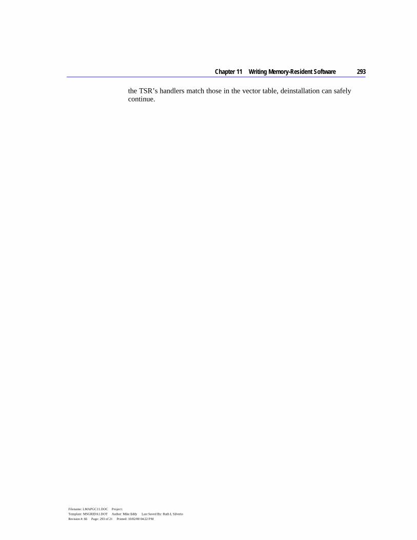
Chapter 11 Writing Memory-Resident Software 293
Filename: LMAPGC11.DOC Project: Template: MSGRIDA1.DOT Author: Mike Eddy Last Saved By: Ruth L Silverio Revision #: 66 Page: 293 of 21 Printed: 10/02/00 04:22 PM
the TSR’s handlers match those in the vector table, deinstallation can safely continue.

294 Programmer’s Guide
Filename: LMAPGC11.DOC Project: Template: MSGRIDA1.DOT Author: Mike Eddy Last Saved By: Ruth L Silverio Revision #: 66 Page: 294 of 22 Printed: 10/02/00 04:22 PM
You can deinstall the TSR with these three steps:
1. Restore to the vector table the original interrupt vectors replaced by the handler addresses.
2. Read the segment address stored at offset 2Ch of the resident TSR’s program segment prefix (PSP). This address points to the TSR’s “environment block,” a list of environment variables that MS-DOS copies into memory when it loads a program. Place the block’s address in the ES register and call MS-DOS Function 49h (Release Memory Block) to return the block’s memory to the operating system.
3. Place the resident PSP segment address in ES and again call Function 49h. This call releases the block of memory occupied by the TSR’s code and data.
The example program in the next section demonstrates how to locate a resident TSR through its multiplex handler, and deinstall it from memory.
Example of an Advanced TSR: SNAP This section presents SNAP, a memory-resident program that demonstrates most of the techniques discussed in this chapter. SNAP takes a snapshot of the current screen and copies the text to a specified file. SNAP accommodates screens with various column and line counts, such as CGA’s 40-column mode or VGA’s 50-line mode. The program ignores graphics screens.
Once installed, SNAP occupies approximately 7.5K of memory. When it detects the ALT+LEFT SHIFT+S key combination, SNAP displays a prompt for a file specification. The user can type a new filename, accept the previous filename by pressing ENTER, or cancel the request by pressing ESC.
SNAP reads text directly from the video buffer and copies it to the specified file. The program sets the file pointer to the end of the file so that text is appended without overwriting previous data. SNAP copies each line only to the last character, ignoring trailing spaces. The program adds a carriage return–linefeed sequence (0D0Ah) to the end of each line. This makes the file accessible to any text editor that can read ASCII files.
To demonstrate how a program accesses resident data through the Multiplex interrupt, SNAP can reset the display attribute of its prompt box. After installing SNAP, run the main program with the /C option to change box colors:
SNAP /Cxx
The argument xx specifies the desired attribute as a two-digit hexadecimal number — for example, 7C for red on white, or 0F for monochrome high

Chapter 11 Writing Memory-Resident Software 295
Filename: LMAPGC11.DOC Project: Template: MSGRIDA1.DOT Author: Mike Eddy Last Saved By: Ruth L Silverio Revision #: 66 Page: 295 of 23 Printed: 10/02/00 04:22 PM
intensity. For a list of color and monochrome display attributes, refer to the “Tables” section of the Reference.
SNAP can deinstall itself, provided another TSR has not been loaded after it. Deinstall SNAP by executing the main program with the /D option:
SNAP /D
If SNAP successfully deinstalls, it displays the following message:
TSR deinstalled
Building SNAP.EXE SNAP combines four modules: SNAP.ASM, COMMON.ASM, HANDLERS.ASM, and INSTALL.ASM. Source files are located on one of your distribution disks. Each module stores temporary code and data in the segments INSTALLCODE and INSTALLDATA. These segments apply only to SNAP’s installation phase; MS-DOS recovers the memory they occupy when the program exits through the terminate-and-stay-resident function. The following briefly describes each module:
u SNAP.ASM contains the TSR’s main code and data. u COMMON.ASM contains procedures used by other example programs. u HANDLERS.ASM contains interrupt handler routines for Interrupts 08, 09,
10h, 13h, 15h, 28h, and 2Fh. It also provides simple error-trapping handlers for Interrupts 1Bh, 23h, and 24h. Additional routines set up and deinstall the handlers.
u INSTALL.ASM contains an exit routine that calls the terminate-and-stay- resident function and a deinstallation routine that removes the program from memory. The module includes error-checking services and a command-line parser.
This building-block approach allows you to create other TSRs by replacing SNAP.ASM and linking with the HANDLERS and INSTALL object modules. The library of routines accommodates both keyboard-activated and time- activated TSRs. A time-activated TSR is a program that activates at a predetermined time of day, similar to the example program ALARM introduced earlier in this chapter. The header comments for the Install procedure in HANDLERS.ASM explain how to install a time-activated TSR.
You can write new TSRs in assembly language or any high-level language that conforms to the Microsoft conventions for ordering segments. Regardless of the language, the new code must not invoke an MS-DOS function that sets up the I/O stack (see “Interrupting MS-DOS Functions,” earlier in this chapter). Code

296 Programmer’s Guide
Filename: LMAPGC11.DOC Project: Template: MSGRIDA1.DOT Author: Mike Eddy Last Saved By: Ruth L Silverio Revision #: 66 Page: 296 of 24 Printed: 10/02/00 04:22 PM
in Microsoft C, for example, must not call getche or kbhit, since these functions in turn call MS-DOS Functions 01 and 0Bh.
Code written in a high-level language must not check for stack overflows. Compiler-generated stack probes do not recognize the new stack setup when the TSR executes, and therefore must be disabled. The example program BELL.C, included on disk with the TSR library routines, demonstrates how to disable stack checking in Microsoft C using the check_stack pragma.
Outline of SNAP The following sections outline in detail how SNAP works. Each part of the outline covers a specific portion of SNAP’s code. Headings refer to earlier sections of this chapter, providing cross-references to SNAP’s key procedures. For example, the part of the outline that describes how SNAP searches for its startup signal refers to the section “Auditing Hardware Events for TSR Requests,” earlier in this chapter.
Figures 11.2 through 11.4 are flowcharts of the SNAP program. Each chart illustrates a separate phase of SNAP’s operation, from installation through memory-residency to deinstallation.
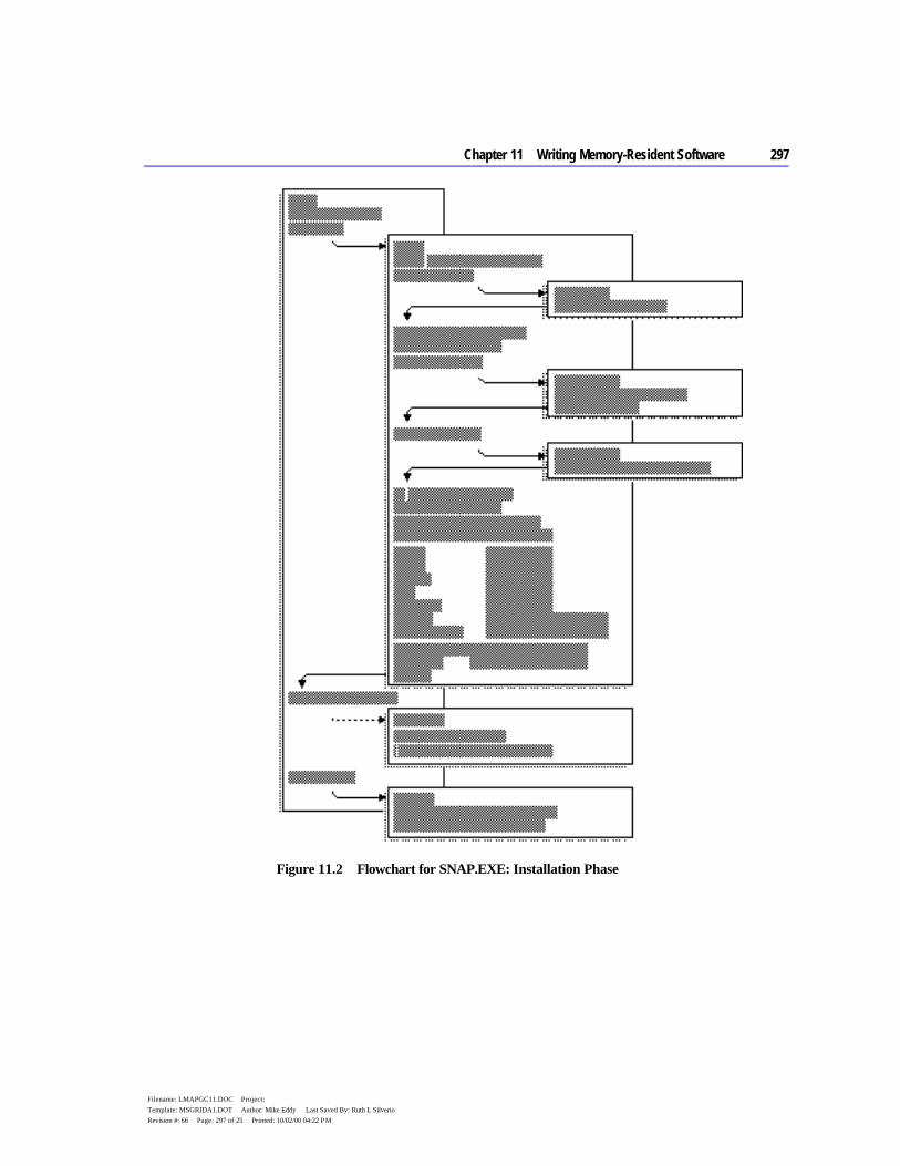
Chapter 11 Writing Memory-Resident Software 297
Filename: LMAPGC11.DOC Project: Template: MSGRIDA1.DOT Author: Mike Eddy Last Saved By: Ruth L Silverio Revision #: 66 Page: 297 of 25 Printed: 10/02/00 04:22 PM
Figure 11.2 Flowchart for SNAP.EXE: Installation Phase
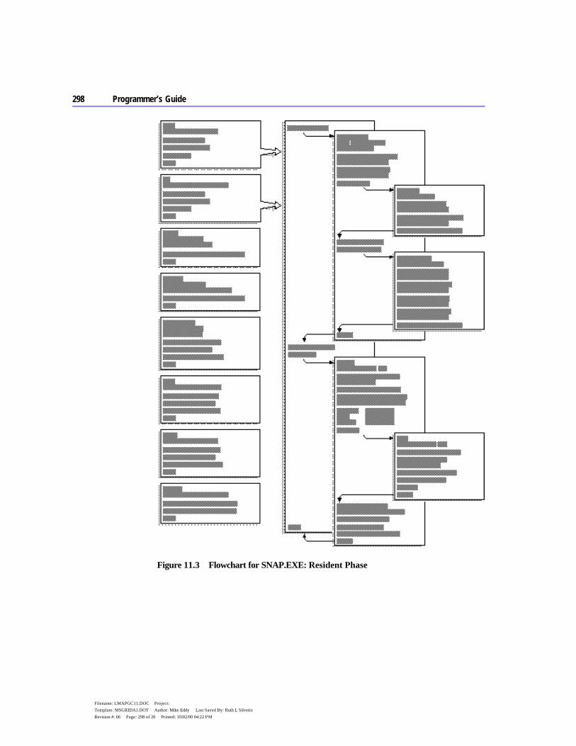
298 Programmer’s Guide
Filename: LMAPGC11.DOC Project: Template: MSGRIDA1.DOT Author: Mike Eddy Last Saved By: Ruth L Silverio Revision #: 66 Page: 298 of 26 Printed: 10/02/00 04:22 PM
Figure 11.3 Flowchart for SNAP.EXE: Resident Phase
Chapter 11 Writing Memory-Resident Software 299
Filename: LMAPGC11.DOC Project: Template: MSGRIDA1.DOT Author: Mike Eddy Last Saved By: Ruth L Silverio Revision #: 66 Page: 299 of 27 Printed: 10/02/00 04:22 PM
Figure 11.4 Flowchart for SNAP.EXE: Deinstallation Phase
Refer to the flowcharts as you read the following outline. They will help you maintain perspective while exploring the details of SNAP’s operation. Text in the outline cross-references the charts.
Note that information in both the outline and the flowcharts is generic. Except for references to the SNAP procedure, all descriptions in the outline and the
300 Programmer’s Guide
Filename: LMAPGC11.DOC Project: Template: MSGRIDA1.DOT Author: Mike Eddy Last Saved By: Ruth L Silverio Revision #: 66 Page: 300 of 28 Printed: 10/02/00 04:22 PM
flowcharts apply to any TSR created with the HANDLERS and INSTALL modules.
Auditing Hardware Events for TSR Requests To search for its startup signal, SNAP audits the keyboard with an interrupt handler for either Interrupt 09 (keyboard) or Interrupt 15h (Miscellaneous System Services). The Install procedure determines which of the two interrupts to handle based on the following code:
.IF HotScan == 0 ; If valid scan code given: mov ah, HotShift ; AH = hour to activate mov al, HotMask ; AL = minute to activate call GetTimeToElapse ; Get number of 5-second intervals mov CountDown, ax ; to elapse before activation .ELSE ; Force use of KeybrdMonitor as ; keyboard handler cmp Version, 031Eh ; DOS Version 3.3 or higher? jb setup ; No? Skip next step ; Test for IBM PS/2 series. If not PS/2, use Keybrd and ; SkipMiscServ as handlers for Interrupts 09 and 15h ; respectively. If PS/2 system, set up KeybrdMonitor as the ; Interrupt 09 handler. Audit keystrokes with MiscServ ; handler, which searches for the hot key by handling calls ; to Interrupt 15h (Miscellaneous System Services). Refer to ; Section 11.2.1 for more information about keyboard handlers. mov ax, 0C00h ; Function 0Ch (Get System int 15h ; Configuration Parameters) sti ; Compaq ROM may leave disabled jc setup ; If carry set, or ah, ah ; or if AH not 0, jnz setup ; services are not supported ; Test bit 4 to see if Intercept is implemented test BYTE PTR es:[bx+5], 00010000y jz setup ; If so, set up MiscServ as Interrupt 15h handler mov ax, OFFSET MiscServ mov WORD PTR intMisc.NewHand, ax .ENDIF ; Set up KeybrdMonitor as Interrupt 09 handler mov ax, OFFSET KeybrdMonitor mov WORD PTR intKeybrd.NewHand, ax
The following describes the code’s logic:
Chapter 11 Writing Memory-Resident Software 301
Filename: LMAPGC11.DOC Project: Template: MSGRIDA1.DOT Author: Mike Eddy Last Saved By: Ruth L Silverio Revision #: 66 Page: 301 of 29 Printed: 10/02/00 04:22 PM
u If the program is running under MS-DOS version 3.3 or higher and if Interrupt 15h supports Function 4Fh, set up handler MiscServ to search for the hot key. Handle Interrupt 09 with KeybrdMonitor only to maintain the keyboard active flag.
u Otherwise, set up a handler for Interrupt 09 to search for the hot key. Handle calls to Interrupt 15h with the routine SkipMiscServ, which contains this single instruction: jmp cs:intMisc.OldHand
The jump immediately passes control to the original Interrupt 15h routine; thus, SkipMiscServ has no effect. It serves only to simplify coding in other parts of the program.
At each keystroke, the keyboard interrupt handler (either Keybrd or MiscServ) calls the procedure CheckHotKey with the scan code of the current key. CheckHotKey compares the scan code and shift status with the bytes HotScan and HotShift. If the current key matches, CheckHotKey returns the carry flag clear to indicate that the user has pressed the hot key.
If the keyboard handler finds the carry flag clear, it sets the flag TsrRequestFlag and exits. Otherwise, the handler transfers control to the original interrupt routine to service the interrupt.
The timer handler Clock reads the request flag at every occurrence of the timer interrupt. Clock takes no action if it finds a zero value in TsrRequestFlag. Figures 11.1 and 11.3 depict the relationship between the keyboard and timer handlers.
Monitoring System Status Because SNAP produces output to both video and disk, it avoids interrupting either video or disk operations. The program uses interrupt handlers Video and DiskIO to monitor Interrupts 10h (video) and 13h (disk). SNAP also avoids interrupting keyboard use. The instructions at the far label KeybrdMonitor serve as the monitor handler for Interrupt 09 (keyboard).
The three handlers perform similar functions. Each sets an active flag and then calls the original routine to service the interrupt. When the service routine returns, the handler clears the active flag to indicate that the device is no longer in use.
302 Programmer’s Guide
Filename: LMAPGC11.DOC Project: Template: MSGRIDA1.DOT Author: Mike Eddy Last Saved By: Ruth L Silverio Revision #: 66 Page: 302 of 30 Printed: 10/02/00 04:22 PM
The BIOS Interrupt 13h routine clears or sets the carry flag to indicate the operation’s success or failure. DiskIO therefore preserves the flags register when returning, as shown here:
DiskIO PROC FAR mov cs:intDiskIO.Flag, TRUE ; Set active flag ; Simulate interrupt by pushing flags and far-calling old ; Int 13h routine pushf call cs:intDiskIO.OldHand ; Clear active flag without disturbing flags register mov cs:intDiskIO.Flag, FALSE sti ; Enable interrupts ; Simulate IRET without popping flags (since services use ; carry flag) ret 2 DiskIO ENDP
The terminating RET 2 instruction discards the original flags from the stack when the handler returns.
Determining Whether to Invoke the TSR The procedure CheckRequest determines whether the TSR:
u Has been requested. u Can safely interrupt the system.
Each time it executes, the timer handler Clock calls CheckRequest to read the flag TsrRequestFlag. If CheckRequest finds the flag set, it scans other flags maintained by the TSR’s interrupt handlers and by MS-DOS. These flags indicate the current system status. As the flowchart in Figure 11.3 shows, CheckRequest calls CheckDos (described following) to determine the status of the operating system. CheckRequest then calls CheckHardware to check hardware status.
CheckHardware queries the interrupt controller to determine if any device is currently being serviced. It also reads the active flags maintained by the KeybrdMonitor, Video, and DiskIO handlers. If the controller, keyboard, video, and disk are all inactive, CheckHardware clears the carry flag and returns.
CheckRequest indicates system status with the carry flag. If the procedure returns the carry flag set, the caller exits without invoking the TSR. A clear carry signals that the caller can safely execute the TSR.
Chapter 11 Writing Memory-Resident Software 303
Filename: LMAPGC11.DOC Project: Template: MSGRIDA1.DOT Author: Mike Eddy Last Saved By: Ruth L Silverio Revision #: 66 Page: 303 of 31 Printed: 10/02/00 04:22 PM
Determining MS-DOS Activity As Figure 11.2 shows, the procedure GetDosFlags locates the InDos flag during SNAP’s installation phase. GetDosFlags calls Function 34h (Get Address of InDos Flag) and then stores the flag’s address in the far pointer InDosAddr.
When called from the CheckRequest procedure, CheckDos reads InDos to determine whether the operating system is active. Note that CheckDos reads the flag directly from the address in InDosAddr. It does not call Function 34h to locate the flag, since it has not yet established whether MS-DOS is active. This follows from the general rule that interrupt handlers must not call any MS-DOS function.
The next two sections more fully describe the procedure CheckDos.
Interrupting MS-DOS Functions Figure 11.3 shows that the call to CheckDos can initiate either from Clock (timer handler) or Idle (Interrupt 28h handler). If CheckDos finds the InDos flag set, it reacts in different ways, depending on the caller:
u If called from Clock, CheckDos cannot know which MS-DOS function is active. In this case, it returns the carry flag set, indicating that Clock must deny the request for the TSR.
u If called from Idle, CheckDos assumes that one of the low-order polling functions is active. It therefore clears the carry flag to let the caller know the TSR can safely interrupt the function.
For more information on this topic, see the section “Interrupting MS-DOS Functions,” earlier in this chapter.
Monitoring the Critical Error Flag The procedure GetDosFlags (Figure 11.2) determines the address of the Critical Error flag. The procedure stores the flag’s address in the far pointer CritErrAddr.
When called from either the Clock or Idle handlers, CheckDos reads the Critical Error flag. A nonzero value in the flag indicates that the Critical Error Handler (Interrupt 24h) is processing a critical error and the TSR must not interrupt. In this case, CheckDos sets the carry flag and returns, causing the caller to exit without executing the TSR.
Trapping Errors As Figure 11.3 shows, Clock and Idle invoke the TSR by calling the procedure Activate. Before calling the main body of the TSR, Activate sets up the following handlers:
304 Programmer’s Guide
Filename: LMAPGC11.DOC Project: Template: MSGRIDA1.DOT Author: Mike Eddy Last Saved By: Ruth L Silverio Revision #: 66 Page: 304 of 32 Printed: 10/02/00 04:22 PM
Handler Name For Interrupt Receives Control When
CtrlBreak 1Bh (CTRL+BREAK Handler) CTRL+BREAK sequence entered at keyboard
CtrlC 23h (CTRL+C Handler) MS-DOS detects a CTRL+C sequence from the keyboard or input stream
CritError 24h (Critical Error Handler) MS-DOS encounters a critical error
These handlers trap keyboard break signals and critical errors that would otherwise trigger the original handler routines. The CtrlBreak and CtrlC handlers contain a single IRET instruction, thus rendering a keyboard break ineffective. The CritError handler contains the following instructions:
CritError PROC FAR sti sub al, al ; Assume DOS 2.x ; Set AL = 0 for ignore error .IF cs:major != 2 ; If DOS 3.x, set AL = 3 mov al, 3 ; DOS call fails .ENDIF iret CritError ENDP
The return code in AL stops MS-DOS from taking further action when it encounters a critical error.
As an added precaution, Activate also calls Function 33h (Get or Set CTRL+BREAK Flag) to determine the current setting of the checking flag. Activate stores the setting, then calls Function 33h again to turn off break checking.
When the TSR’s main procedure finishes its work, it returns to Activate, which restores the original setting for the checking flag. It also replaces the original vectors for Interrupts 1Bh, 23h, and 24h.
SNAP’s error-trapping safeguards enable the TSR to retain control in the event of an error. Pressing CTRL+BREAK or CTRL+C at SNAP’s prompt has no effect. If the user specifies a nonexistent drive — a critical error — SNAP merely beeps the speaker and returns normally.
Preserving an Existing Condition Activate records the stack pointer SS:SP in the doubleword OldStackAddr. The procedure then resets the pointer to the address of a new stack before calling the TSR. Switching stacks ensures that SNAP has adequate stack depth while it executes.
The label NewStack points to the top of the new stack buffer, located in the code segment of the HANDLERS.ASM module. The equate constant

Chapter 11 Writing Memory-Resident Software 305
Filename: LMAPGC11.DOC Project: Template: MSGRIDA1.DOT Author: Mike Eddy Last Saved By: Ruth L Silverio Revision #: 66 Page: 305 of 33 Printed: 10/02/00 04:22 PM
STACK_SIZ determines the size of the stack. The include file TSR.INC contains the declaration for STACK_SIZ.
Activate preserves the values in all registers by pushing them onto the new stack. It does not push DS, since that register is already preserved in the Clock or Idle handler.
SNAP does not alter the application’s video configuration other than by moving the cursor. Figure 11.3 shows that Activate calls the procedure Snap, which executes Interrupt 10h to determine the current cursor position. Snap stores the row and column in the word OldPos. The procedure restores the cursor to its original location before returning to Activate.
Preserving Existing Data Because SNAP does not call an MS-DOS function that writes to the DTA, it does not need to preserve the DTA belonging to the interrupted process. However, the code for switching and restoring the DTA is included within IFDEF blocks in the procedure Activate. The equate constant DTA_SIZ, declared in the TSR.INC file, governs the assembly of the blocks as well as the size of the new DTA.
It is possible for SNAP to overwrite existing extended error information by committing a file error. The program does not attempt to preserve the original information by calling Functions 59h and 5Dh. In certain rare instances, this may confuse the interrupted process after SNAP returns.
Communicating Through the Multiplex Interrupt The program uses the Multiplex interrupt (Interrupt 2Fh) to
u Verify that SNAP is installed. u Select a unique multiplex identity number. u Locate resident data.
For more information about Interrupt 2Fh, see the section “Communicating through the Multiplex Interrupt,” earlier in this chapter.
SNAP accesses Interrupt 2Fh through the procedure CallMultiplex, as shown in Figures 11.2 and 11.4. By searching for a prior installation, CallMultiplex ensures that SNAP is not installed more than once. During deinstallation, CallMultiplex locates data required to deinstall the resident TSR.
The procedure Multiplex serves as SNAP’s multiplex handler. When it recognizes its identity number in AH, Multiplex determines its tasks from the function number in the AL register. The handler responds to Function 0 by

306 Programmer’s Guide
Filename: LMAPGC11.DOC Project: Template: MSGRIDA1.DOT Author: Mike Eddy Last Saved By: Ruth L Silverio Revision #: 66 Page: 306 of 34 Printed: 10/02/00 04:22 PM
returning AL equalling 0FFh and ES:DI pointing to an identifier string unique to SNAP.
CallMultiplex searches for the handler by invoking Interrupt 2Fh in a loop, beginning with a trial identity number of 192 in AH. At the start of each iteration of the loop, the procedure sets AL to zero to request presence verification from the multiplex handler. If the handler returns 0FFh in AL, CallMultiplex compares its copy of SNAP’s identifier string with the text at memory location ES:DI. A failed match indicates that the multiplex handler servicing the call is not SNAP’s handler. In this case, CallMultiplex increments AH and cycles back to the beginning of the loop.
The process repeats until the call to Interrupt 2Fh returns a matching identifier string at ES:DI, or until AL returns as zero. A matching string verifies that SNAP is installed, since its multiplex handler has serviced the call. A return value of zero indicates that SNAP is not installed and that no multiplex handler claims the trial identity number in AH. In this case, SNAP assigns the number to its own handler.
Deinstalling a TSR During deinstallation, CallMultiplex locates SNAP’s multiplex handler as described previously. The handler Multiplex receives the verification request and returns in ES the code segment of the resident program.
Deinstall reads the addresses of the following interrupt handlers from the data structure in the resident code segment:
Handler Name Description
Clock Timer handler Keybrd Keyboard handler (non-PS/2) KeybrdMonitor Keyboard monitor handler (PS/2) Video Video monitor handler DiskIO Disk monitor handler SkipMiscServ Miscellaneous Systems Services handler (non-PS/2) MiscServ Miscellaneous Systems Services handler (PS/2) Idle MS-DOS Idle handler Multiplex Multiplex handler
Deinstall calls MS-DOS Function 35h (Get Interrupt Vector) to retrieve the current vectors for each of the listed interrupts. By comparing each handler address with the corresponding vector, Deinstall ensures that SNAP can be safely deinstalled. Failure in any of the comparisons indicates that another TSR has been installed after SNAP and has set up a handler for the same interrupt. In

Chapter 11 Writing Memory-Resident Software 307
Filename: LMAPGC11.DOC Project: Template: MSGRIDA1.DOT Author: Mike Eddy Last Saved By: Ruth L Silverio Revision #: 66 Page: 307 of 35 Printed: 10/02/00 04:22 PM
this case, Deinstall returns an error code, stopping the program with the following message:
Can’t deinstall TSR
If all addresses match, Deinstall calls Interrupt 2Fh with SNAP’s identity number in AH and AL set to 1. The handler Multiplex responds by returning in ES the address of the resident code’s PSP. Deinstall then calls MS-DOS Function 25h (Set Interrupt Vector) to restore the vectors for the original service routines. This is called “unhooking” or “unchaining” the interrupt handlers.
After unhooking all of SNAP’s interrupt handlers, Deinstall returns with AX pointing to the resident code’s PSP. The procedure FreeTsr then calls MS-DOS Function 49h (Release Memory) to return SNAP’s memory to the operating system. The program ends with the message
TSR deinstalled
to indicate a successful deinstallation.
Deinstalling SNAP does not guarantee more available memory space for the next program. If another TSR loads after SNAP but handles interrupts other than 08, 09, 10h, 13h, 15h, 28h, or 2Fh, SNAP still deinstalls properly. The result is a harmless gap of deallocated memory formerly occupied by SNAP. MS-DOS can use the free memory to store the next program’s environment block. However, MS-DOS loads the program itself above the still-resident TSR.
307
Filename: LMAPGC12.DOC Project: Template: MSGRIDA1.DOT Author: Mike Eddy Last Saved By: Ruth L Silverio Revision #: 71 Page: 307 of 1 Printed: 10/02/00 04:21 PM
C H A P T E R 1 2
Mixed-language programming allows you to combine the unique strengths of Microsoft Basic, C, C++, and FORTRAN with your assembly-language routines. Any one of these languages can call MASM routines, and you can call any of these languages from within your assembly-language programs. This makes virtually all the routines from high-level–language libraries available to a mixed-language program.
MASM 6.1 provides mixed-language features similar to those in high-level languages. For example, you can use the INVOKE directive to call high-level-language procedures, and the assembler handles the argument-passing details for you. You can also use H2INC to translate C header files to MASM include files, as explained in Chapter 20 of Environment and Tools.
The mixed-language features of MASM 6.1 do not make older methods of defining mixed-language interfaces obsolete. In most cases, mixed-language programs written with earlier versions of MASM will assemble and link correctly under MASM 6.1. (For more information, see Appendix A.)
This chapter explains how to write assembly routines that can be called from high-level–language modules and how to call high-level language routines from MASM. You should already understand the languages you want to combine and should know how to write, compile, and link multiple-module programs with these languages.
This chapter covers only assembly-language interface with C, C++, Basic, and FORTRAN; it does not cover mixed-language programming between high-level languages. The focus here is the Microsoft versions of C, C++, Basic, and FORTRAN, but the same principles apply to other languages and compilers. Many of the techniques used in this chapter are explained in the material in Chapter 7 on writing procedures in assembly language, and in Chapter 8 on multiple-module programming.
The first section of this chapter discusses naming and calling conventions. The next section, “Writing an Assembly Procedure for a Mixed-Language Program,” provides a template for writing an assembly-language procedure that can be
Mixed-Language Programming
308 Programmer’s Guide
Filename: LMAPGC12.DOC Project: Template: MSGRIDA1.DOT Author: Mike Eddy Last Saved By: Ruth L Silverio Revision #: 71 Page: 308 of 2 Printed: 10/02/00 04:21 PM
called from another module written in a high-level language. This represents the essence of mixed-language programming. Assembly language is often used for creating fast secondary routines in a large program written in a high-level language.
The third section describes specific conventions for linking assembly-language procedures with modules in C, C++, Basic, and FORTRAN. These language-specific sections also provide details on how the language manages various data structures so that your MASM programs are compatible with the data from the high-level language.
Naming and Calling Conventions Each language has its own set of conventions, which fall into two categories:
u The “naming convention” specifies how or if the compiler or assembler alters the name of an identifier before placing it into an object file.
u The “calling convention” determines how a language implements a call to a procedure and how the procedure returns to the caller.
MASM supports several different conventions. The assembler uses C convention when you specify a language type (langtype) of C, and Pascal convention for language types PASCAL, BASIC, or FORTRAN. To the assembler, the keywords BASIC, PASCAL, and FORTRAN are synonymous. MASM also supports the SYSCALL and STDCALL conventions, which mix elements of the C and Pascal conventions.
MASM gives you several ways to set the naming and calling conventions in your assembly-language program. Using .MODEL with a langtype sets the default for the module. This can also be done with the OPTION directive. This is equivalent to the /Gc or /Gd option from the command line. Procedure prototypes and declarations can specify a langtype to override the default.
When you write mixed-language routines, the easiest way to ensure convention compatibility is to adopt the conventions of the called procedure’s language. However, Microsoft languages can change the naming and calling conventions for different procedures. If your program must call a procedure that uses an argument-passing method different from that of the default language, prototype the procedure first with the desired language type. This tells the assembler to override the conventions of the default language and assume the proper conventions for the prototyped procedure. “The MASM/High-Level–Language Interface” section in this chapter explains how to change the default conventions. The following sections provide more detail on the information summarized in Table 12.1.
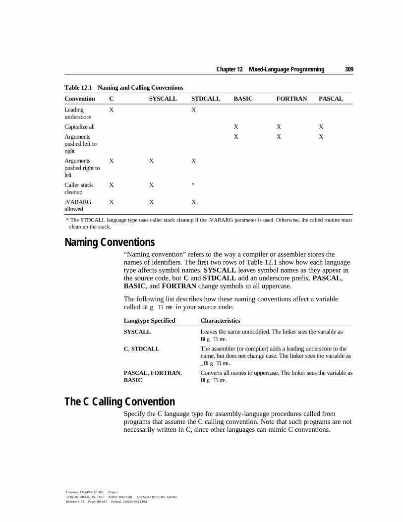
Chapter 12 Mixed-Language Programming 309
Filename: LMAPGC12.DOC Project: Template: MSGRIDA1.DOT Author: Mike Eddy Last Saved By: Ruth L Silverio Revision #: 71 Page: 309 of 3 Printed: 10/02/00 04:21 PM
Table 12.1 Naming and Calling Conventions
Convention C SYSCALL STDCALL BASIC FORTRAN PASCAL
Leading underscore
X X
Capitalize all X X X Arguments pushed left to right
X X X
Arguments pushed right to left
X X X
Caller stack cleanup
X X *
:VARARG allowed
X X X
* The STDCALL language type uses caller stack cleanup if the :VARARG parameter is used. Otherwise, the called routine must clean up the stack.
Naming Conventions “Naming convention” refers to the way a compiler or assembler stores the names of identifiers. The first two rows of Table 12.1 show how each language type affects symbol names. SYSCALL leaves symbol names as they appear in the source code, but C and STDCALL add an underscore prefix. PASCAL, BASIC, and FORTRAN change symbols to all uppercase.
The following list describes how these naming conventions affect a variable called Big Time in your source code:
Langtype Specified Characteristics
SYSCALL Leaves the name unmodified. The linker sees the variable as Big Time.
C, STDCALL The assembler (or compiler) adds a leading underscore to the name, but does not change case. The linker sees the variable as _Big Time.
PASCAL, FORTRAN, BASIC
Converts all names to uppercase. The linker sees the variable as Big Time.
The C Calling Convention Specify the C language type for assembly-language procedures called from programs that assume the C calling convention. Note that such programs are not necessarily written in C, since other languages can mimic C conventions.
310 Programmer’s Guide
Filename: LMAPGC12.DOC Project: Template: MSGRIDA1.DOT Author: Mike Eddy Last Saved By: Ruth L Silverio Revision #: 71 Page: 310 of 4 Printed: 10/02/00 04:21 PM
Argument Passing With the C calling convention, the caller pushes arguments from right to left as they appear in the caller’s argument list. The called procedure returns without removing the arguments from the stack. It is the caller’s responsibility to clean the stack after the call, either by popping the arguments or by adding an appropriate value to the stack pointer SP.
Register Preservation The called routine must return with the original values in BP, SI, DI, DS, and SS. It must also preserve the direction flag.
Varying Number of Arguments The additional overhead of cleaning the stack after each call has compensations. It frees the caller from having to pass a set number of arguments to the called procedure each time. Because the first argument in the list is always the last one pushed, it is always on the top of the stack. Thus, it has the same address relative to the frame pointer, regardless of how many arguments were actually passed.
For example, consider the C library function printf, which accepts different numbers of arguments. A C program calls the function like this:
printf( "Numbers: %f %f %.2f\n", n1, n2, n3 ); printf( "Also: %f", n4 );
The first line passes four arguments (including the string in quotes) and the second line passes only two arguments. Notice that printf has no reliable way of determining how many arguments the caller has pushed. Therefore, the function returns without adjusting the stack. The C calling convention requires the caller to take responsibility for removing the arguments from the stack, since only the caller knows how many arguments it passed.
Use INVOKE to call a C-callable function from your assembly-language program, since INVOKE automatically generates the necessary stack-cleaning code after the call. You must also prototype the function with the VARARG keyword if appropriate, as explained in “Procedures,” Chapter 7. Similarly, when you write a C-callable procedure that accepts a varying number of arguments, include VARARG in the procedure’s PROC statement.
The Pascal Calling Convention By default, the langtype for FORTRAN, BASIC, and PASCAL selects the Pascal calling convention. This convention pushes arguments left to right so that the last argument is lowest on the stack, and it requires that the called routine remove arguments from the stack.
Chapter 12 Mixed-Language Programming 311
Filename: LMAPGC12.DOC Project: Template: MSGRIDA1.DOT Author: Mike Eddy Last Saved By: Ruth L Silverio Revision #: 71 Page: 311 of 5 Printed: 10/02/00 04:21 PM
Argument Passing Arguments are placed on the stack in the same order in which they appear in the source code. The first argument is highest in memory (because it is also the first argument to be placed on the stack), and the stack grows downward.
Register Preservation A routine that uses the Pascal calling convention must preserve SI, DI, BP, DS, and SS. For 32-bit code, the EBX, ES, FS, and GS registers must be preserved as well as EBP, ESI, and EDI. The direction flag is also cleared upon entry and must be preserved.
Varying Number of Arguments Passing a variable number of arguments is not possible with the Pascal calling convention.
The STDCALL and SYSCALL Calling Conventions A STDCALL procedure adopts the C name and calling conventions when prototyped with the VARARG keyword. Refer to the section “Declaring Parameters with the PROC Directive” in Chapter 7. Without VARARG, the procedure uses the C naming and Pascal calling conventions. STDCALL provides compatibility with 32-bit versions of Microsoft compilers.
As Table 12.1 shows, SYSCALL is identical to the C calling convention, but does not add an underscore prefix to symbols.
Argument Passing Argument passing order for both STDCALL and SYSCALL is the same as the C calling convention. The caller pushes the arguments from right to left and must remove the parameters from the stack after the call. However, STDCALL requires the called procedure to clean the stack if the procedure does not accept a variable number of arguments.
Register Preservation Both conventions require the called procedure to preserve the registers BP, SI, DI, DS, and SS. Under STDCALL, the direction flag is clear on entry and must be returned clear.
Varying Number of Arguments SYSCALL allows a variable number of arguments in the same way as the C calling convention. STDCALL also mimics the C convention when VARARG appears in the called procedure’s declaration or definition. It allows a varying number of arguments and requires the caller to clean the stack. If not declared
312 Programmer’s Guide
Filename: LMAPGC12.DOC Project: Template: MSGRIDA1.DOT Author: Mike Eddy Last Saved By: Ruth L Silverio Revision #: 71 Page: 312 of 6 Printed: 10/02/00 04:21 PM
or defined with VARARG, the called procedure does not accept a variable argument list and must clean the stack before it returns.
Writing an Assembly Procedure For a Mixed-Language Program
MASM 6.1 simplifies the coding required for linking MASM routines to high-level– language routines. You can use the PROTO directive to write procedure prototypes, and the INVOKE directive to call external routines. MASM simplifies procedure-related tasks in the following ways:
u The PROTO directive improves error checking on argument types. uu INVOKE pushes arguments onto the stack and converts argument types to
types expected when possible. These arguments can be referenced by their parameter label, rather than as offsets of the stack pointer.
u The LOCAL directive following the PROC statement saves places on the stack for local variables. These variables can also be referenced by name, rather than as offsets of the stack pointer.
uu PROC sets up the appropriate stack frame according to the processor mode. u The USES keyword preserves registers given as arguments. u The C calling conventions specified in the PROC syntax allow for a variable
number of arguments to be passed to the procedure. u The RET keyword adjusts the stack upward by the number of bytes in the
argument list, removes local variables from the stack, and pops saved registers.
u The PROC statement lists parameter names and types. The parameters can be referenced by name inside the procedure.
The complete syntax and parameter descriptions for these procedure directives are explained in “Procedures” in Chapter 7. This section provides a template that you can use for writing a MASM routine to be called from a high-level language.
The template looks like this:
Label PROC [[distance langtype visibility <prologueargs> USES reglist parmlist]] LOCAL varlist . . .
Chapter 12 Mixed-Language Programming 313
Filename: LMAPGC12.DOC Project: Template: MSGRIDA1.DOT Author: Mike Eddy Last Saved By: Ruth L Silverio Revision #: 71 Page: 313 of 7 Printed: 10/02/00 04:21 PM
RET Label ENDP
Replace the italicized words with appropriate keywords, registers, or variables as defined by the syntax in “Declaring Parameters with the PROC Directive” in Chapter 7.
The distance (NEAR or FAR) and visibility (PUBLIC, PRIVATE, or EXPORT) that you give in the procedure declaration override the current defaults. In some languages, the model can also be specified with command-line options.
The langtype determines the calling convention for accessing arguments and restoring the stack. For information on calling conventions, see “Naming and Calling Conventions” earlier in this chapter.
The types for the parameters listed in the parmlist must be given. Also, if any of the parameters are pointers, the assembler does not generate code to get the value of the pointer references. You must write this code yourself. An example of how to write such code is provided in “Declaring Parameters with the PROC Directive” in Chapter 7.
If you need to code your own stack-frame setup manually, or if you do not want the assembler to generate the standard stack setup and cleanup, see “Passing Arguments on the Stack” and “User-Defined Prologue and Epilogue Code” in Chapter 7.
The MASM/High-Level–Language Interface Since high-level–language programs require initialization, you must write the main routine of a mixed-language program in the high-level language, or link with the startup code supplied by the high-level–language compiler. This gives the assembly code access to high-level routines or library functions. The next section explains how to link an assembly-language program with C-language startup code.
For procedures with prototypes, INVOKE makes calls from MASM to high-level– language programs, much like procedure or function calls in the high-level language. INVOKE calls procedures and generates the code to push arguments in the order specified by the procedure’s calling convention, and to remove arguments from the stack at the end of the procedure.
INVOKE can also do type checking and data conversion for the argument types so that the procedure receives compatible data. For explanations of how to write procedure prototypes and several examples of procedure declarations and the corresponding prototypes, see “Declaring Procedure Prototypes” in Chapter 7.
314 Programmer’s Guide
Filename: LMAPGC12.DOC Project: Template: MSGRIDA1.DOT Author: Mike Eddy Last Saved By: Ruth L Silverio Revision #: 71 Page: 314 of 8 Printed: 10/02/00 04:21 PM
For programs that mix assembly language and C, the H2INC utility makes it easy to write prototypes and data declarations for the C procedures you want to call from MASM. H2INC translates the C prototypes and declarations into the corresponding MASM prototypes and declarations, which INVOKE can use to call the procedure. The use of H2INC is explained in Chapter 20 in Environment and Tools.
Mixed-language programming also allows the main program or a routine to use external data — data defined in the other module. External data is the data that is stored in a set place in memory (unlike dynamic and local data, which is allocated on the stack and heap) and is visible to other modules.
External data is shared by all routines. One of the modules must define the static data, which causes the compiler to allocate storage for the data. The other modules that access the data must declare the data as external.
Argument Passing Each language has its own convention for how an argument is actually passed. If the argument-passing conventions of your routines do not agree, then a called routine receives bad data. Microsoft languages support three different methods for passing an argument:
u Near reference. Passes a variable’s near (offset) address, expressed as an offset from the default data segment. This method gives the called routine direct access to the variable itself. Any change the routine makes to the parameter is reflected in the calling routine.
u Far reference. Passes a variable’s far (segmented) address. Though slower than passing a near reference, this method is necessary for passing data that lies outside the default data segment. (This is not an issue in Basic unless you have specifically requested far memory.)
u Value. Passes only a copy of the variable, not its address. With this method, the called routine gets a copy of the argument on the stack, but has no access to the original variable. The copy is discarded when the routine returns, and the variable retains its original value.
When you pass arguments between routines written in different languages, you must ensure that the caller and the called routine use the same conventions for passing and receiving arguments. In most cases, you should check the argument-passing defaults used by each language and make any necessary adjustments. Most languages have features that allow you to change argument-passing methods.
Chapter 12 Mixed-Language Programming 315
Filename: LMAPGC12.DOC Project: Template: MSGRIDA1.DOT Author: Mike Eddy Last Saved By: Ruth L Silverio Revision #: 71 Page: 315 of 9 Printed: 10/02/00 04:21 PM
Register Preservation A procedure called from any high-level language should preserve the direction flag and the values of BP, SI, DI, SS, and DS. Routines called from MASM must not alter SI, DI, SS, DS, or BP.
Pushing Addresses Microsoft high-level languages push segment addresses before offsets. This lets the called routine use the LES and LDS instructions to read far addresses from the stack. Furthermore, each word of an argument is placed on the stack in order of significance. Thus, the high word of a long integer is pushed first, followed by the low word.
Array Storage Most high-level-language compilers store arrays in row-major order. This means that all elements of a row are stored consecutively. The first five elements of an array with four rows and three columns are stored in row-major order as
A[1, 1], A[1, 2], A[1, 3], A[2, 1], A[2, 2]
In column-major order, the column elements are stored consecutively. For example, this same array would be stored in column-major order as
A[1, 1], A[2, 1], A[3, 1], A[4, 1], A[1, 2], A[2, 2]
The C/MASM Interface This section summarizes the characteristics of the interface between MASM and Microsoft C and QuickC compilers. With the default naming and calling convention, the assembler (or compiler) pushes arguments right to left and adds a leading underscore to routine names.
Compatible Data Types This list shows the 16-bit C data types and equivalent data types in MASM 6.1. For 32-bit C compilers, int and unsigned int are equivalent to the MASM types SDWORD and DWORD, respectively.
C Type Equivalent MASM Type
unsigned char BYTE char SBYTE unsigned short, unsigned int WORD int, short SWORD unsigned long DWORD long SDWORD
316 Programmer’s Guide
Filename: LMAPGC12.DOC Project: Template: MSGRIDA1.DOT Author: Mike Eddy Last Saved By: Ruth L Silverio Revision #: 71 Page: 316 of 10 Printed: 10/02/00 04:21 PM
float REAL4 double REAL8 long double REAL10
Naming Restrictions C is case-sensitive and does not convert names to uppercase. Since C normally links with the /NOI command-line option, you should assemble MASM modules with the /Cx or /Cp option to prevent the assembler from converting names to uppercase.

Chapter 12 Mixed-Language Programming 317
Filename: LMAPGC12.DOC Project: Template: MSGRIDA1.DOT Author: Mike Eddy Last Saved By: Ruth L Silverio Revision #: 71 Page: 317 of 11 Printed: 10/02/00 04:21 PM
Argument-Passing Defaults C always passes arrays by reference and all other variables (including structures) by value. C programs in tiny, small, and medium model pass near addresses for arrays, unless another distance is specified. Compact-, large-, and huge-model programs pass far addresses by default. To pass by reference a variable type other than array, use the C-language address-of operator (&).
If you need to pass an array by value, declare the array as a structure member and pass a copy of the entire structure. However, this practice is rarely necessary and usually impractical except for very small arrays, since it can make substantial demands on stack space. If your program must maintain an array through a procedure call, create a temporary copy of the array in heap and provide the copy to the procedure by reference.
Changing the Calling Convention Put _pascal or _fortran in the C function declaration to specify the Pascal calling convention.
Array Storage Array declarations give the number of elements. A1[a][b] declares a two-dimensional array in C with a rows and b columns. By default, the array’s lower bound is zero. Arrays are stored by the compiler in row-major order. By default, passing arrays from C passes a pointer to the first element of the array.
String Format C stores strings as arrays of bytes and uses a null character as the end-of-string delimiter. For example, consider the string declared as follows:
char msg[] = "string of text"
The string occupies 15 bytes of memory as:
Figure 12.1 C String Format
Since msg is an array of characters, it is passed by reference.
External Data In C, the extern keyword tells the compiler that the data or function is external. You can define a static data object in a C module by defining a data object outside all functions and subroutines. Do not use the static keyword in C with a data object that you want to be public.
318 Programmer’s Guide
Filename: LMAPGC12.DOC Project: Template: MSGRIDA1.DOT Author: Mike Eddy Last Saved By: Ruth L Silverio Revision #: 71 Page: 318 of 12 Printed: 10/02/00 04:21 PM
Structure Alignment By default, C uses word alignment (unpacked storage) for all data objects longer than 1 byte. This storage method specifies that occasional bytes may be added as padding, so that word and doubleword objects start on an even boundary. In addition, all nested structures and records start on a word boundary. MASM aligns on byte boundaries by default.
When converting .H files with H2INC, you can use the /Zp command-line option to specify structure alignment. If you do not specify the /Zp option, H2INC uses word-alignment. Without H2INC, set the alignment to 2 when declaring the MASM structure, compile the C module with /Zp1, or assemble the MASM module with /Zp2.
Compiling and Linking Use the same memory model for both C and MASM.
Returning Values The assembler returns simple data types in registers. Table 12.2 shows the register conventions for returning simple data types to a C program.
Table 12.2 Register Conventions for Simple Return Values
Data Type Registers
char AL short, near, int (16-bit) AX short, near, int (32-bit) EAX long, far (16-bit) High-order portion (or segment address) in DX;
low-order portion (or offset address) in AX
long, far (32-bit) High-order portion (or segment address) in EDX; low-order portion (or offset address) in EAX
Procedures using the C calling convention and returning type float or type double store their return values into static variables. In multi-threaded programs, this could mean that the return value may be overwritten. You can avoid this by using the Pascal calling convention for multi-threaded programs so float or double values are passed on the stack.
Structures less than 4 bytes long are returned in DX:AX. To return a longer structure from a procedure that uses the C calling convention, you must copy the structure to a global variable and then return a pointer to that variable in the AX register (DX:AX, if you compiled in compact, large, or huge model or if the variable is declared as a far pointer).

Chapter 12 Mixed-Language Programming 319
Filename: LMAPGC12.DOC Project: Template: MSGRIDA1.DOT Author: Mike Eddy Last Saved By: Ruth L Silverio Revision #: 71 Page: 319 of 13 Printed: 10/02/00 04:21 PM
Structures, Records, and User-Defined Data Types You can pass structures, records, and user-defined types as arguments by value or by reference.
Writing Procedure Prototypes The H2INC utility simplifies the task of writing prototypes for the C functions you want to call from MASM. The C prototype converted by H2INC into a MASM prototype allows INVOKE to correctly call the C function. Here are some examples of C functions and the MASM prototypes created with H2INC.
/* Function Prototype Declarations to Convert with H2INC */ long checktypes ( char *name, unsigned char a, int b, float d, unsigned int *num ); my_func (float fNum, unsigned int x); extern my_func1 (char *argv[]); struct videoconfig _far * _far pascal my_func2 (int, scri );
For these C prototypes, H2INC generates this code:
@proto_0 TYPEDEF PROTO C :PTR SBYTE, :BYTE, :SWORD, :REAL4, :PTR WORD checktypes PROTO @proto_0 @proto_1 TYPEDEF PROTO C :REAL4, :WORD my_func PROTO @proto_1 @proto_2 TYPEDEF PROTO C :PTR PTR SBYTE my_func1 PROTO @proto_2 @proto_3 TYPEDEF PROTO FAR PASCAL :SWORD, :scri my_func2 PROTO @proto_3
320 Programmer’s Guide
Filename: LMAPGC12.DOC Project: Template: MSGRIDA1.DOT Author: Mike Eddy Last Saved By: Ruth L Silverio Revision #: 71 Page: 320 of 14 Printed: 10/02/00 04:21 PM
Example As shown in the following short example, the main module (written in C) calls an assembly routine, Power2.
#include <stdio.h> extern int Power2( int factor, int power ); void main() { printf( "3 times 2 to the power of 5 is %d\n", Power2( 3, 5 ) ); }
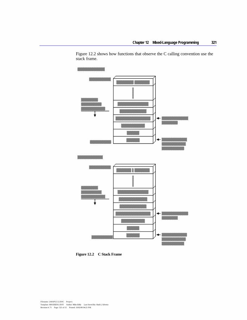
Chapter 12 Mixed-Language Programming 321
Filename: LMAPGC12.DOC Project: Template: MSGRIDA1.DOT Author: Mike Eddy Last Saved By: Ruth L Silverio Revision #: 71 Page: 321 of 15 Printed: 10/02/00 04:21 PM
Figure 12.2 shows how functions that observe the C calling convention use the stack frame.
Figure 12.2 C Stack Frame
322 Programmer’s Guide
Filename: LMAPGC12.DOC Project: Template: MSGRIDA1.DOT Author: Mike Eddy Last Saved By: Ruth L Silverio Revision #: 71 Page: 322 of 16 Printed: 10/02/00 04:21 PM
The MASM module that contains the Power2 routine looks like this:
.MODEL small, c Power2 PROTO C factor:SWORD, power:SWORD .CODE Power2 PROC C factor:SWORD, power:SWORD mov ax, factor ; Load Arg1 into AX mov cx, power ; Load Arg2 into CX shl ax, cl ; AX = AX * (2 to power of CX) ; Leave return value in AX ret Power2 ENDP END
The MASM procedure declaration for the Power2 routine specifies the C langtype and the parameters expected by the procedure. The langtype specifies the calling and naming conventions for the interface between MASM and C. The routine is public by default. When the C module calls Power2, it passes two arguments, 3 and 5 by value.
Using the C Startup Code This section explains how to write an assembly-language program that can call C library functions. It links with the C startup module, which performs the necessary initialization required by the library functions.
You must follow these steps when writing such a program:
1. Specify the C convention in the .MODEL statement. 2. Include the following (optional) statement to note linkage with the C startup
module: EXTERN _acrtused:abs
3. Prototype or declare as external all C functions the program references. 4. Include a public procedure called main in your assembly-language module.
The C startup code calls _main (which is why all C programs begin with a main function). This procedure serves as the effective entry point for your program.
5. Omit an entry point in the program’s END directive. The C startup code serves as the true entry point when the program runs.
6. Assemble with ML’s /Cx switch to preserve the case of nonlocal names.
Chapter 12 Mixed-Language Programming 323
Filename: LMAPGC12.DOC Project: Template: MSGRIDA1.DOT Author: Mike Eddy Last Saved By: Ruth L Silverio Revision #: 71 Page: 323 of 17 Printed: 10/02/00 04:21 PM
The following example serves as a template for these steps. The program calls the C run-time function printf to display two variables.
.MODEL small, c ; Step 1: declare C conventions EXTERN _acrtused:abs ; Step 2: bring in C startup . . . printf PROTO NEAR, ; Step 3: prototype pstring:NEAR PTR BYTE, ; external C num1:WORD, num2:VARARG ; routines .DATA format BYTE '%i %i', 13, 0 .CODE main PROC PUBLIC ; Step 4: C startup calls here . . . INVOKE printf, OFFSET format, ax, bx . . . END ; Step 5: no label on END
The C++/MASM Interface C++ can apply a protocol called a “linkage specification” to mixed-language procedures. This lets you link C++ code in the same way as C code. All information in the preceding section applies when linking assembly-language and C++ routines through the C linkage specification.
The C linkage specification forces the C++ compiler to adopt C conventions — which are not the same as C++ conventions — for listed routines. Since MASM does not specifically support C++ conventions, set the C linkage specification in your C++ code for all mixed-language routines, as shown here:
extern “C” declaration
where declaration is the prototype of an exported C++ function or an imported assembly-language procedure. You can bracket a list of declarations:
extern "C" { int WriteLine( short attr, char *string ); void GoExit( int err ); }
324 Programmer’s Guide
Filename: LMAPGC12.DOC Project: Template: MSGRIDA1.DOT Author: Mike Eddy Last Saved By: Ruth L Silverio Revision #: 71 Page: 324 of 18 Printed: 10/02/00 04:21 PM
or apply the specification to individual prototypes:
extern "C" int WriteLine( short attr, char *string ); extern "C" void GoExit( int err );
Note the syntax remains the same whether WriteLine and GoExit are exported C++ functions or imported assembly-language routines. The linkage specification applies only to called routines, not to external variables. Use the extern keyword (without the “C”) as you normally would when identifying objects external to the C++ module.
The FORTRAN/MASM Interface This section summarizes the specific details important to calling FORTRAN procedures or receiving arguments from FORTRAN routines that call MASM routines. It includes a sample MASM and FORTRAN module.
A FORTRAN procedure follows the Pascal calling convention by default. This convention passes arguments in the order listed, and the calling procedure removes the arguments from the stack. The naming convention converts all exported names to uppercase.
Compatible Data Types This list shows the FORTRAN data types that are equivalent to the MASM 6.1 data types.
FORTRAN Type Equivalent MASM Type
CHARACTER*1 BYTE INTEGER*1 SBYTE INTEGER*2 SWORD REAL*4 REAL4 INTEGER*4 SDWORD REAL*8, DOUBLE PRECISION REAL8
Naming Restrictions FORTRAN allows 31 characters for identifier names. A digit or an underscore cannot be the first character in an identifier name.
Argument-Passing Defaults By default, FORTRAN passes arguments by reference as far addresses if the FORTRAN module is compiled in large or huge memory model. It passes them as near addresses if the FORTRAN module is compiled in medium model. Versions of FORTRAN prior to Version 4.0 always require large model.
Chapter 12 Mixed-Language Programming 325
Filename: LMAPGC12.DOC Project: Template: MSGRIDA1.DOT Author: Mike Eddy Last Saved By: Ruth L Silverio Revision #: 71 Page: 325 of 19 Printed: 10/02/00 04:21 PM
The FORTRAN compiler passes an argument by value when declared with the VALUE attribute. This declaration can occur either in a FORTRAN INTERFACE block (which determines how to pass an argument) or in a function or subroutine declaration (which determines how to receive an argument).
In FORTRAN you can apply the NEAR (or FAR) attribute to reference parameters. These keywords override the default. They have no effect when they specify the same method as the default.
Changing the Calling Convention A call to a FORTRAN function or subroutine declared with the PASCAL or C attribute passes all arguments by value in the parameter list (except for parameters declared with the REFERENCE attribute). This change in default passing method applies to function and subroutine definitions as well as to the functions and subroutines described by INTERFACE blocks.
Array Storage When you declare FORTRAN arrays, you can specify any integer for the lower bound (the default is 1). The FORTRAN compiler stores all arrays in column-major order — that is, the leftmost subscript increments most rapidly. For example, the first seven elements of an array defined as A[3,4] are stored as
A[1,1], A[2,1], A[3,1], A[1,2], A[2,2], A[3,2], A[1,3]
String Format FORTRAN stores strings as a series of bytes at a fixed location in memory, with no delimiter at the end of the string. When passing a variable-length FORTRAN string to another language, you need to devise a method by which the target routine can find the end of the string.
Consider the string declared as
CHARACTER*14 MSG MSG = 'String of text'
The string is stored in 14 bytes of memory like this:
Figure 12.3 FORTRAN String Format
326 Programmer’s Guide
Filename: LMAPGC12.DOC Project: Template: MSGRIDA1.DOT Author: Mike Eddy Last Saved By: Ruth L Silverio Revision #: 71 Page: 326 of 20 Printed: 10/02/00 04:21 PM
Strings are passed by reference. Although FORTRAN has a method for passing length, the variable-length FORTRAN strings cannot be used in a mixed- language interface because other languages cannot access the temporary variable that FORTRAN uses to communicate string length. However, fixed-length strings can be passed if the FORTRAN INTERFACE statement declares the length of the string in advance.
External Data FORTRAN routines can directly access external data. In FORTRAN you can declare data to be external by adding the EXTERN attribute to the data declaration. You can also access a FORTRAN variable from MASM if it is declared in a COMMON block.
A FORTRAN program can call an external assembly procedure with the use of the INTERFACE statement. However, the INTERFACE statement is not strictly necessary unless you intend to change one of the FORTRAN defaults.
Structure Alignment By default, FORTRAN uses word alignment (unpacked storage) for all data objects larger than 1 byte. This storage method specifies that occasional bytes may be added as padding, so that word and doubleword objects start on an even boundary. In addition, all nested structures and records start on a word boundary. The MASM default is byte-alignment, so you should specify an alignment of 2 for MASM structures or use the /Zp1 option when compiling in FORTRAN.
Compiling and Linking Use the same memory model for the MASM and FORTRAN modules.
Returning Values You must use a special convention to return floating-point values, records, user-defined types, arrays, and values larger than 4 bytes to a FORTRAN module from an assembly procedure. The FORTRAN module creates space in the stack segment to hold the actual return value. When the call to the assembly procedure is made, an extra parameter is passed. This parameter is the last one pushed. The segment address of the return value is contained in SS.
In the assembly procedure, put the data for the return value at the location pointed to by the return value offset. Then copy the return-value offset (located at BP + 6) to AX, and copy SS to DX. This is necessary because the calling module expects DX:AX to point to the return value.
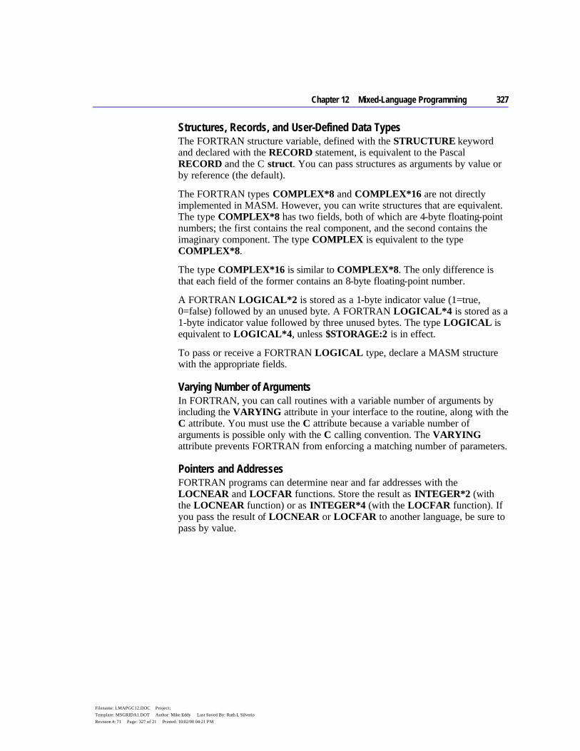
Chapter 12 Mixed-Language Programming 327
Filename: LMAPGC12.DOC Project: Template: MSGRIDA1.DOT Author: Mike Eddy Last Saved By: Ruth L Silverio Revision #: 71 Page: 327 of 21 Printed: 10/02/00 04:21 PM
Structures, Records, and User-Defined Data Types The FORTRAN structure variable, defined with the STRUCTURE keyword and declared with the RECORD statement, is equivalent to the Pascal RECORD and the C struct. You can pass structures as arguments by value or by reference (the default).
The FORTRAN types COMPLEX*8 and COMPLEX*16 are not directly implemented in MASM. However, you can write structures that are equivalent. The type COMPLEX*8 has two fields, both of which are 4-byte floating-point numbers; the first contains the real component, and the second contains the imaginary component. The type COMPLEX is equivalent to the type COMPLEX*8.
The type COMPLEX*16 is similar to COMPLEX*8. The only difference is that each field of the former contains an 8-byte floating-point number.
A FORTRAN LOGICAL*2 is stored as a 1-byte indicator value (1=true, 0=false) followed by an unused byte. A FORTRAN LOGICAL*4 is stored as a 1-byte indicator value followed by three unused bytes. The type LOGICAL is equivalent to LOGICAL*4, unless $STORAGE:2 is in effect.
To pass or receive a FORTRAN LOGICAL type, declare a MASM structure with the appropriate fields.
Varying Number of Arguments In FORTRAN, you can call routines with a variable number of arguments by including the VARYING attribute in your interface to the routine, along with the C attribute. You must use the C attribute because a variable number of arguments is possible only with the C calling convention. The VARYING attribute prevents FORTRAN from enforcing a matching number of parameters.
Pointers and Addresses FORTRAN programs can determine near and far addresses with the LOCNEAR and LOCFAR functions. Store the result as INTEGER*2 (with the LOCNEAR function) or as INTEGER*4 (with the LOCFAR function). If you pass the result of LOCNEAR or LOCFAR to another language, be sure to pass by value.

328 Programmer’s Guide
Filename: LMAPGC12.DOC Project: Template: MSGRIDA1.DOT Author: Mike Eddy Last Saved By: Ruth L Silverio Revision #: 71 Page: 328 of 22 Printed: 10/02/00 04:21 PM
Example In the following example, the FORTRAN module calls an assembly procedure that calculates A*2^B, where A and B are the first and second parameters, respectively. This is done by shifting the bits in A to the left B times.
INTERFACE TO INTEGER*2 FUNCTION POWER2(A, B) INTEGER*2 A, B END PROGRAM MAIN INTEGER*2 POWER2 INTEGER*2 A, B A = 3 B = 5 WRITE (*, *) '3 TIMES 2 TO THE B OR 5 IS ',POWER2(A, B) END
To understand the assembly procedure, consider how the parameters are placed on the stack, as illustrated in Figure 12.4.
Figure 12.4 FORTRAN Stack Frame
Figure 12.4 assumes that the FORTRAN module is compiled in large model. If you compile the FORTRAN module in medium model, then each argument is passed as a 2-byte, not 4-byte, address. The return address is 4 bytes long because procedures called from FORTRAN must always be FAR.
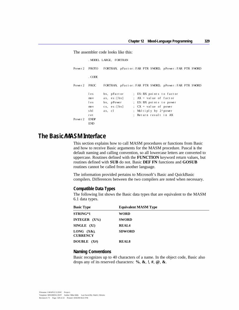
Chapter 12 Mixed-Language Programming 329
Filename: LMAPGC12.DOC Project: Template: MSGRIDA1.DOT Author: Mike Eddy Last Saved By: Ruth L Silverio Revision #: 71 Page: 329 of 23 Printed: 10/02/00 04:21 PM
The assembler code looks like this:
.MODEL LARGE, FORTRAN Power2 PROTO FORTRAN, pFactor:FAR PTR SWORD, pPower:FAR PTR SWORD .CODE Power2 PROC FORTRAN, pFactor:FAR PTR SWORD, pPower:FAR PTR SWORD les bx, pFactor ; ES:BX points to factor mov ax, es:[bx] ; AX = value of factor les bx, pPower ; ES:BX points to power mov cx, es:[bx] ; CX = value of power shl ax, cl ; Multiply by 2^power ret ; Return result in AX Power2 ENDP END
The Basic/MASM Interface This section explains how to call MASM procedures or functions from Basic and how to receive Basic arguments for the MASM procedure. Pascal is the default naming and calling convention, so all lowercase letters are converted to uppercase. Routines defined with the FUNCTION keyword return values, but routines defined with SUB do not. Basic DEF FN functions and GOSUB routines cannot be called from another language.
The information provided pertains to Microsoft’s Basic and QuickBasic compilers. Differences between the two compilers are noted when necessary.
Compatible Data Types The following list shows the Basic data types that are equivalent to the MASM 6.1 data types.
Basic Type Equivalent MASM Type
STRING*1 WORD INTEGER (X%) SWORD SINGLE (X!) REAL4 LONG (X&), CURRENCY
SDWORD
DOUBLE (X#) REAL8
Naming Conventions Basic recognizes up to 40 characters of a name. In the object code, Basic also drops any of its reserved characters: %, &, !, #, @, &.

330 Programmer’s Guide
Filename: LMAPGC12.DOC Project: Template: MSGRIDA1.DOT Author: Mike Eddy Last Saved By: Ruth L Silverio Revision #: 71 Page: 330 of 24 Printed: 10/02/00 04:21 PM
Argument-Passing Defaults Basic can pass data in several ways and can receive it by value or by near reference. By default, Basic arguments are passed by near reference as 2-byte addresses. To pass a near address, pass only the offset; if you need to pass a far address, pass the segment and offset separately as integer arguments. Pass the segment address first, unless you have specified C compatibility with the CDECL keyword.
Basic passes each argument in a call by far reference when CALLS is used to invoke a routine. You can also use SEG to modify a parameter in a preceding DECLARE statement so that Basic passes that argument by far reference. To pass any other variable type by value, apply the BYVAL keyword to the argument in the DECLARE statement. You cannot pass arrays and user-defined types by value.
DECLARE SUB Test(BYVAL a%, b%, SEG c%) CALL Test(x%, y%, z%) CALLS Test(x%, y%, z%)
This CALL statement passes the first argument (a%) by value, the second argument (b%) by near reference, and the third argument (c%) by far reference. The statement
CALLS Test2(x%, y%, z%)
passes each argument by far reference.
Changing the Calling Convention Including the CDECL keyword in the Basic DECLARE statement enables the C calling and naming conventions. This also allows a call to a MASM procedure with a varying number of arguments.
Array Storage The DIM statement sets the number of dimensions for a Basic array and also sets the array’s maximum subscript value. In the array declaration DIM x(a,b), the upper bounds (the maximum number of values possible) of the array are a and b. The default lower bound is 0. The default upper bound for an array subscript is 10.
The default for column storage in Basic is column-major order, as in FORTRAN. For an array defined as DIM Arr%(3,3), reference the last element as Arr%(3,3). The first five elements of Arr (3,3) are
Arr(0,0), Arr(1,0), Arr(2,0), Arr(0,1), Arr(1,1)

Chapter 12 Mixed-Language Programming 331
Filename: LMAPGC12.DOC Project: Template: MSGRIDA1.DOT Author: Mike Eddy Last Saved By: Ruth L Silverio Revision #: 71 Page: 331 of 25 Printed: 10/02/00 04:21 PM
When you pass an array from Basic to a language that stores arrays in row-major order, use the command-line option /R when compiling the Basic module.
Most Microsoft languages permit you to reference arrays directly. Basic uses an array descriptor, however, which is similar in some respects to a Basic string descriptor. The array descriptor is necessary because Basic handles memory allocation for arrays dynamically, and thus may shift the location of the array in memory.
A reference to an array in Basic is really a near reference to an array descriptor. Array descriptors are always in DGROUP, even though the data may be in far memory. Array descriptors contain information about type, dimensions, and memory locations of data. You can safely pass arrays to MASM routines only if you follow three rules:
u Pass the array’s address by applying the VARPTR function to the first element of the Basic array and passing the result by value. To pass the far address of the array, apply both the VARPTR and VARSEG functions and pass each result by value. The receiving language gets the address of the first element and considers it to be the address of the entire array. It can then access the array with its normal array-indexing syntax.
u The MASM routine that receives the array should not call back to one of the calling program’s routines before it has finished processing the array. Changing data within the caller’s heap — even data unrelated to the array — may change the array’s location in the heap. This would invalidate any further work the called routine performs, since the routine would be operating on the array’s old location.
u Basic can pass any member of an array by value. When passing individual array elements, these restrictions do not apply.
You can apply LBOUND and UBOUND to a Basic array to determine lower and upper bounds, and then pass the results to another routine. This way, the size of the array does not need to be determined in advance.
String Format Basic maintains a 4-byte string descriptor for each string, as shown in the following. The first field of the string descriptor contains a 2-byte integer indicating the length of the actual string text. The second field contains the offset address of this text within the caller’s data segment.
Figure 12.5 Basic String Descriptor Format
332 Programmer’s Guide
Filename: LMAPGC12.DOC Project: Template: MSGRIDA1.DOT Author: Mike Eddy Last Saved By: Ruth L Silverio Revision #: 71 Page: 332 of 26 Printed: 10/02/00 04:21 PM
An assembly-language procedure can store a Basic string descriptor as a simple structure, like this:
DESC STRUCT len WORD ? ; Length of string off WORD ? ; Offset of string DESC ENDS string BYTE "This text referenced by a string descriptor" sdesc DESC (LENGTHOF string, string)
Version 7.0 or later of the Microsoft Basic Compiler provides new functions that access string descriptors. These functions simplify the process of sharing Basic string data with routines written in other languages.
Earlier versions of Basic offer the LEN (Length) and SADD (String Address) functions, which together obtain the information stored in a string descriptor. LEN returns the length of a string in bytes. SADD returns the offset address of a string in the data segment. The caller must provide both pieces of information so the called procedure can locate and read the entire string. The address returned by SADD is declared as type INTEGER but is actually equivalent to a C near pointer.
If you need to pass the far address of a string, use the SSEGADD (String Segment Address) function of Microsoft Basic version 7.0 or later. You can also determine the segment address of the first element with VARSEG.
External Data Declaring global data in Basic follows the same two-step process as in other languages:
1. Declare shareable data in Basic with the COMMON statement. 2. Identify the shared variables in your assembly-language procedures with the
EXTERN keyword. Place the EXTERN statement outside of a code or data segment when declaring far data.
Structure Alignment Basic packs user-defined types. For MASM structures to be compatible, select byte-alignment.
Compiling and Linking Always use medium model in assembly-language procedures linked with Basic modules. If you are listing other libraries on the LINK command line, specify Basic libraries first. (There are differences between the QBX and command-line compilation. See your Basic documentation.)

Chapter 12 Mixed-Language Programming 333
Filename: LMAPGC12.DOC Project: Template: MSGRIDA1.DOT Author: Mike Eddy Last Saved By: Ruth L Silverio Revision #: 71 Page: 333 of 27 Printed: 10/02/00 04:21 PM
Returning Values Basic follows the usual convention of returning values in AX or DX:AX. If the value is not floating point, an array, or a structured type, or if it is less than 4 bytes long, then the 2-byte integers should be returned from the MASM procedure in AX and 4-byte integers should be returned in DX:AX. For all other types, return the near offset in AX.
User-Defined Data Types The Basic TYPE statement defines structures composed of individual fields. These types are equivalent to the C struct, FORTRAN record (declared with the STRUCTURE keyword), and Pascal Record types.
You can use any of the Basic data types except variable-length strings or dynamic arrays in a user-defined type. Once defined, Basic types can be passed only by reference.
Varying Number of Arguments You can vary the number of arguments in Basic when you change the calling convention with CDECL. To call a function with a varying number of arguments, you also need to suppress the type checking that normally forces a call to be made with a fixed number of arguments. In Basic, you can remove this type checking by omitting a parameter list from the DECLARE statement.
Pointers and Addresses VARSEG returns a variable’s segment address, and VARPTR returns a variable’s offset address. These intrinsic Basic functions enable your program to pass near or far addresses.
Example This example calls the Power2 procedure in the MASM 6.1 module.
DEFINT A-Z DECLARE FUNCTION Power2 (A AS INTEGER, B AS INTEGER) PRINT "3 times 2 to the power of 5 is "; PRINT Power2(3, 5) END
The first argument, A, is higher in memory than B because Basic pushes arguments in the same order in which they appear.
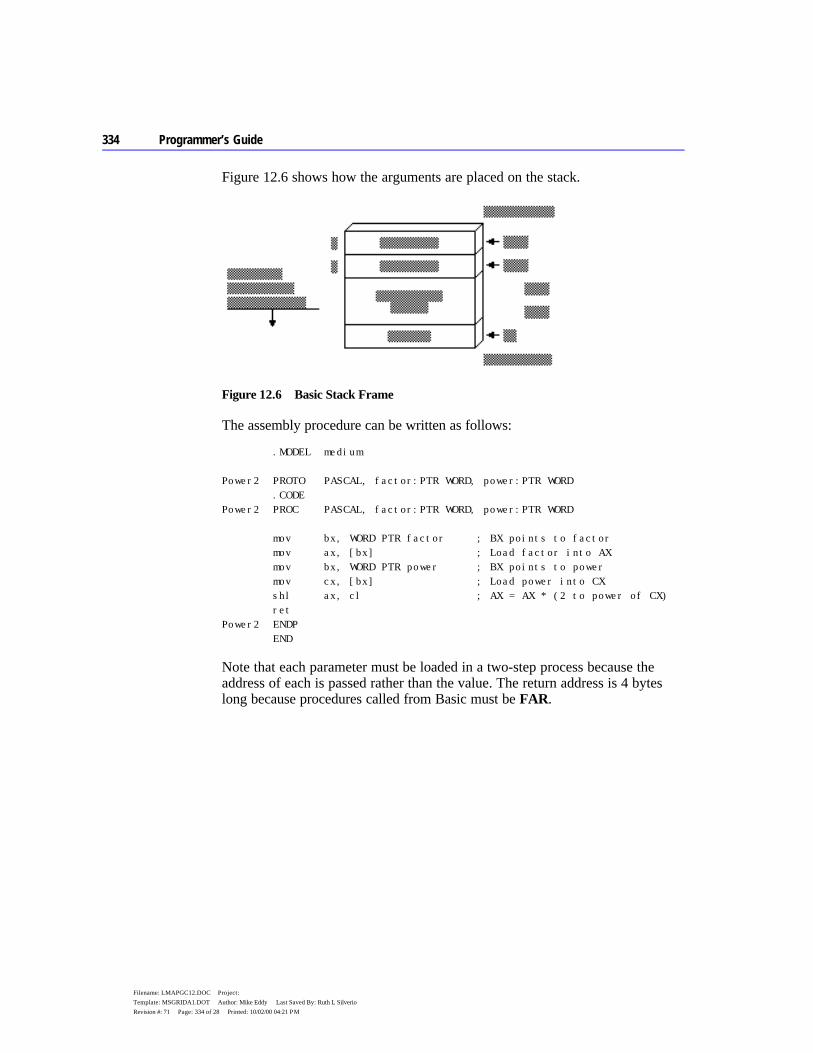
334 Programmer’s Guide
Filename: LMAPGC12.DOC Project: Template: MSGRIDA1.DOT Author: Mike Eddy Last Saved By: Ruth L Silverio Revision #: 71 Page: 334 of 28 Printed: 10/02/00 04:21 PM
Figure 12.6 shows how the arguments are placed on the stack.
Figure 12.6 Basic Stack Frame
The assembly procedure can be written as follows:
.MODEL medium Power2 PROTO PASCAL, factor:PTR WORD, power:PTR WORD .CODE Power2 PROC PASCAL, factor:PTR WORD, power:PTR WORD mov bx, WORD PTR factor ; BX points to factor mov ax, [bx] ; Load factor into AX mov bx, WORD PTR power ; BX points to power mov cx, [bx] ; Load power into CX shl ax, cl ; AX = AX * (2 to power of CX) ret Power2 ENDP END
Note that each parameter must be loaded in a two-step process because the address of each is passed rather than the value. The return address is 4 bytes long because procedures called from Basic must be FAR.


334 Programmer’s Guide
Filename: LMAPGC12.DOC Project: Template: MSGRIDA1.DOT Author: Mike Eddy Last Saved By: Ruth L Silverio Revision #: 71 Page: 334 of 30 Printed: 10/02/00 04:21 PM
335
Filename: LMAPGC13.DOC Project: Template: MSGRIDA1.DOT Author: Terri Sharkey Last Saved By: Ruth L Silverio Revision #: 27 Page: 335 of 1 Printed: 10/02/00 04:21 PM
C H A P T E R 1 3
This chapter is an introduction to 32-bit programming for the 80386. The guidelines in this chapter also apply to the 80486 processor, which is basically a faster 80386 with the equivalent of a 80387 floating-point processor. Since you are already familiar with 16-bit real-mode programming, this chapter covers the differences between 16-bit programming and 32-bit protected-mode programming.
The 80386 processor (and its successors such as the 80486) can run in real mode, virtual-86 mode, and in protected mode. In real and virtual-86 modes, the 80386 can run 8086/8088 programs. In protected mode, it can run 80286 programs. The 386 also extends the features of protected mode to include 32-bit operations and segments larger than 64K.
The MS-DOS operating system directly supports 8086/8088 programs, which it runs either in real mode or virtual-86 mode. Native 32-bit 80386 programs can be run by using a “DOS extender,” by using the WINMEM32.DLL facility of Microsoft Windows 3.x, or by running a native 32-bit operating system, such as Microsoft Windows NT. You can use MASM to generate object code (OMF or COFF) for 32-bit programs. To do this, you will need a software development kit such as the Windows SDK for the target environment. Such kits include the linker and other components specific to your chosen operating environment.
32-Bit Memory Addressing The 80386 has six segment registers. Four of these are familiar to 8086/8088 programmers: CS (Code Segment), SS (Stack Segment), DS (Data Segment), and ES (Extra Segment). The two additional registers, FS and GS, are used as data segment registers.
Memory addresses on 80x86 machines consist of two parts — a segment and an offset. In real-mode programs, the segment is a 16-bit number and the offset is a 16-bit number. Effective addresses are calculated by multiplying the segment by
Writing 32-Bit Applications
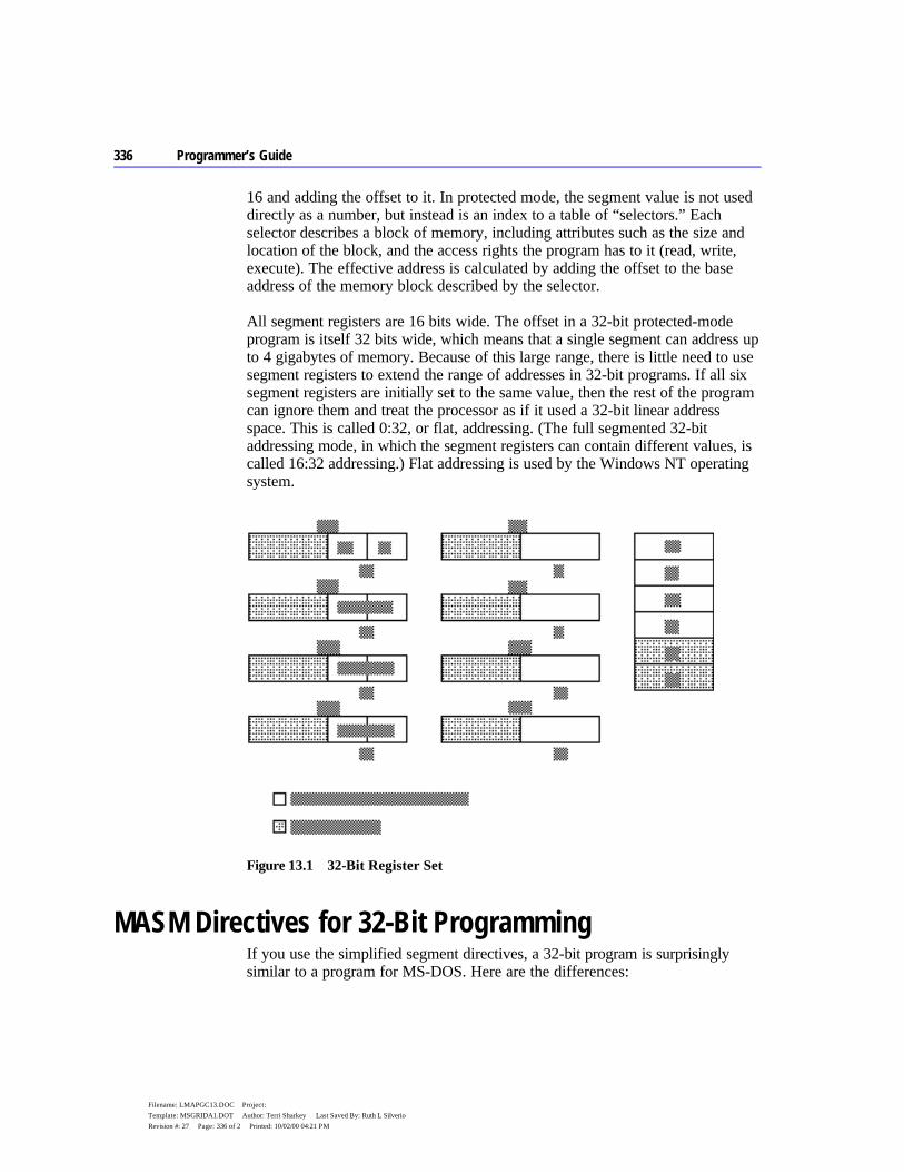
336 Programmer’s Guide
Filename: LMAPGC13.DOC Project: Template: MSGRIDA1.DOT Author: Terri Sharkey Last Saved By: Ruth L Silverio Revision #: 27 Page: 336 of 2 Printed: 10/02/00 04:21 PM
16 and adding the offset to it. In protected mode, the segment value is not used directly as a number, but instead is an index to a table of “selectors.” Each selector describes a block of memory, including attributes such as the size and location of the block, and the access rights the program has to it (read, write, execute). The effective address is calculated by adding the offset to the base address of the memory block described by the selector.
All segment registers are 16 bits wide. The offset in a 32-bit protected-mode program is itself 32 bits wide, which means that a single segment can address up to 4 gigabytes of memory. Because of this large range, there is little need to use segment registers to extend the range of addresses in 32-bit programs. If all six segment registers are initially set to the same value, then the rest of the program can ignore them and treat the processor as if it used a 32-bit linear address space. This is called 0:32, or flat, addressing. (The full segmented 32-bit addressing mode, in which the segment registers can contain different values, is called 16:32 addressing.) Flat addressing is used by the Windows NT operating system.
Figure 13.1 32-Bit Register Set
MASM Directives for 32-Bit Programming If you use the simplified segment directives, a 32-bit program is surprisingly similar to a program for MS-DOS. Here are the differences:
Chapter 13 Writing 32-Bit Applications 337
Filename: LMAPGC13.DOC Project: Template: MSGRIDA1.DOT Author: Terri Sharkey Last Saved By: Ruth L Silverio Revision #: 27 Page: 337 of 3 Printed: 10/02/00 04:21 PM
u Supply the .386 directive, which enables the 32-bit programming features of the 386 and its successors. The .386 directive must precede the .MODEL directive.
u For flat-model programming, use the directive
.MODEL flat, stdcall
which tells the assembler to assume flat model (0:32) and to use the Windows NT standard calling convention for subroutine calls.
u Precede your data declarations with the .DATA directive. u Precede your instruction codes with the .CODE directive. u At the end of the source file, place an END directive.
Sample Program The following sample is a 32-bit assembly language subroutine, such as might be called from a 32-bit C program written for the Windows NT operating system. The program illustrates the use of a variety of directives to make assembly language easier to read and maintain. Note that with 32-bit flat model programming, there is no longer any need to refer to segment registers, since these are artifacts of segmented addressing.

338 Programmer’s Guide
Filename: LMAPGC13.DOC Project: Template: MSGRIDA1.DOT Author: Terri Sharkey Last Saved By: Ruth L Silverio Revision #: 27 Page: 338 of 4 Printed: 10/02/00 04:21 PM
;* szSearch - An example of 32-bit assembly programming using MASM 6.1 ;* ;* Purpose: Search a buffer (rgbSearch) of length cbSearch for the ;* first occurrence of szTok (null terminated string). ;* ;* Method: A variation of the Boyer-Moore method ;* 1. Determine length of szTok (n) ;* 2. Set array of flags (rgfInTok) to TRUE for each character ;* in szTok ;* 3. Set current position of search to rgbSearch (pbCur) ;* 4. Compare current position to szTok by searching backwards ;* from the nth position. When a comparison fails at ;* position (m), check to see if the current character ;* in rgbSearch is in szTok by using rgfInTok. If not, ;* set pbCur to pbCur+(m)+1 and restart compare. If ;* pbCur reached, increment pbCur and restart compare. ;* 5. Reset rgfInTok to all 0 for next instantiation of the ;* routine. .386 .MODEL flat, stdcall FALSE EQU 0 TRUE EQU NOT FALSE

Chapter 13 Writing 32-Bit Applications 339
Filename: LMAPGC13.DOC Project: Template: MSGRIDA1.DOT Author: Terri Sharkey Last Saved By: Ruth L Silverio Revision #: 27 Page: 339 of 5 Printed: 10/02/00 04:21 PM
.DATA ; Flags buffer - data initialized to FALSE. We will ; set the appropriate flags to TRUE during initialization ; of szSearch and reset them to FALSE before exit. rgfInTok BYTE 256 DUP (FALSE); .CODE PBYTE TYPEDEF PTR BYTE szSearch PROC PUBLIC USES esi edi, rgbSearch:PBYTE, cbSearch:DWORD, szTok:PBYTE ; Initialize flags buffer. This tells us if a character is in ; the search token - Note how we use EAX as an index ; register. This can be done with all extended registers. mov esi, szTok xor eax, eax .REPEAT lodsb mov BYTE PTR rgfInTok[eax], TRUE .UNTIL (!AL) ; Save count of szTok bytes in EDX mov edx, esi sub edx, szTok dec edx ; ESI will always point to beginning of szTok mov esi, szTok ; EDI will point to current search position ; and will also contain the return value mov edi, rgbSearch ; Store pointer to end of rgbSearch in EBX mov ebx, edi add ebx, cbSearch sub ebx, edx

340 Programmer’s Guide
Filename: LMAPGC13.DOC Project: Template: MSGRIDA1.DOT Author: Terri Sharkey Last Saved By: Ruth L Silverio Revision #: 27 Page: 340 of 6 Printed: 10/02/00 04:21 PM
; Initialize ECX with length of szTok mov ecx, edx .WHILE ( ecx != 0 ) dec ecx ; Move index to current mov al, [edi+ecx] ; characters to compare ; If the current byte in the buffer doesn't exist in the ; search token, increment buffer pointer to current position ; +1 and start over. This can skip up to 'EDX' ; bytes and reduce search time. .IF !(rgfInTok[eax]) add edi, ecx inc edi ; Initialize ECX with mov ecx, edx ; length of szTok ; Otherwise, if the characters match, continue on as if ; we have a matching token .ELSEIF (al == [esi+ecx]) .CONTINUE ; Finally, if we have searched all szTok characters, ; and land here, we have a mismatch and we increment ; our pointer into rgbSearch by one and start over. .ELSEIF (!ecx) inc edi mov ecx, edx .ENDIF ; Verify that we haven't searched beyond the buffer. .IF (edi > ebx) mov edi, 0 ; Error value .BREAK .ENDIF .ENDW ; Restore flags in rgfInTok to 0 (for next time). mov esi, szTok xor eax, eax .REPEAT lodsb mov BYTE PTR rgfInTok[eax], FALSE .UNTIL !AL ; Put return value in eax mov eax, edi ret szSearch ENDP end


340 Programmer’s Guide
Filename: LMAPGC13.DOC Project: Template: MSGRIDA1.DOT Author: Terri Sharkey Last Saved By: Ruth L Silverio Revision #: 27 Page: 340 of 8 Printed: 10/02/00 04:21 PM
341
Filename: LMAPGAPA.DOC Project: Template: MSGRIDA1.DOT Author: Ruth L Silverio Last Saved By: Ruth L Silverio Revision #: 2 Page: 341 of 1 Printed: 10/02/00 04:18 PM
A P P E N D I X A
For the many users who come to version 6.1 of the Microsoft Macro Assembler directly from the popular MASM 5.1, this appendix describes the differences between the two versions. Version 6.1 contains significant changes, including:
u An integrated development environment called Programmer’s WorkBench (PWB) from which you can write, edit, debug, and execute code.
u Expanded functionality for structures, unions, and type definitions. u New directives for generating loops and decision statements, and for
declaring and calling procedures. u Simplified methods for applying public attributes to variables and routines in
multiple-module programs. u Enhancements for writing and using macros. u Flat-model support for Windows NT and new instructions for the 80486
processor.
The OPTION M510 directive (or the /Zm command-line switch) assures nearly complete compatibility between MASM 6.1 and MASM 5.1. However, to take full advantage of the enhancements in MASM 6.1, you will need to rewrite some code written for MASM 5.1.
The first section of this appendix describes the new or enhanced features in MASM 6.1. The second section, “Compatibility Between MASM 5.1 and 6.1,” explains how to:
u Minimize the number of required changes with the OPTION directive. u Rewrite your existing assembly code, if necessary, to take advantage of the
assembler’s enhancements.
Differences Between MASM 6.1 and 5.1
342 Programmer’s Guide
Filename: LMAPGAPA.DOC Project: Template: MSGRIDA1.DOT Author: Ruth L Silverio Last Saved By: Ruth L Silverio Revision #: 2 Page: 342 of 2 Printed: 10/02/00 04:18 PM
New Features of Version 6.1 This section gives an overview of the new features of MASM 6.1 and provides references to more detailed information elsewhere in the documentation. For full explanations and coding examples, see the documentation listed in the cross-references.
The Assembler, Environment, and Utilities Most of the executable files provided with MASM 6.1 are new or revised. For a complete list of these files, read the PACKING.TXT file on the distribution disk. The book Getting Started also provides information about setting up the environment, assembler, and Help system.
The Assembler The macro assembler, named ML.EXE, can assemble and link in one step. Its new 32-bit operation gives ML.EXE the ability to handle much larger source files than MASM 5.1. The command-line options are new. For example, the /Fl and /Sc options generate instruction timings in the listing file. Command-line options are case-sensitive and must be separated by spaces.
For backward compatibility with MASM 5.1 makefiles, MASM 6.1 includes the MASM.EXE utility. MASM.EXE translates MASM 5.1 command-line options to the new MASM 6.1 command-line options and calls ML.EXE. See the Reference book for details.
H2INC H2INC converts C include files to MASM include files. It translates data structures and declarations but does not translate executable code. For more information, see Chapter 20 of Environment and Tools.
NMAKE NMAKE replaces the MAKE utility. NMAKE provides new functions for evaluating target files and more flexibility with macros and command-line options. For more information, see Environment and Tools.
Integrated Environment PWB is an integrated development environment for writing, developing, and debugging programs. For information on PWB and the CodeView debugging application, see Environment and Tools.
Online Help MASM 6.1 incorporates the Microsoft Advisor Help system. Help provides a vast database of online help about all aspects of MASM, including the syntax

Appendix A Differences Between MASM 6.1 and 5.1 343
Filename: LMAPGAPA.DOC Project: Template: MSGRIDA1.DOT Author: Ruth L Silverio Last Saved By: Ruth L Silverio Revision #: 2 Page: 343 of 3 Printed: 10/02/00 04:18 PM
and timings for processor and coprocessor instructions, directives, command-line options, and support programs such as LINK and PWB.
For information on how to set up the help system, see Getting Started. You can invoke the help system from within PWB or from the QuickHelp program (QH).
HELPMAKE You can use the HELPMAKE utility to create additional help files from ASCII text files, allowing you to customize the online help system. For more information, see Environment and Tools.
Other Programs MASM 6.1 contains the most recent versions of LINK, LIB, BIND, CodeView, and the mouse driver. The CREF program is not included in MASM 6.1. The Source Browser provides the information that CREF provided under MASM 5.1. For more information on the Source Browser, see Chapter 5 of Environment and Tools or Help.
Segment Management This section lists the changes and additions to memory-model support and directives that relate to memory model.
Predefined Symbols The following predefined symbols (also called predefined equates) provide information about simplified segments:
Predefined Symbol Value
@stack DGROUP for near stacks, STACK for far stacks @Interface Information about language parameters @Model Information about the current memory model @Line The source line in the current file @Date The current date @FileCur The current file @Time The current time @Environ The current environment variables
For more information about predefined symbols, see “Predefined Symbols” in Chapter 1.
344 Programmer’s Guide
Filename: LMAPGAPA.DOC Project: Template: MSGRIDA1.DOT Author: Ruth L Silverio Last Saved By: Ruth L Silverio Revision #: 2 Page: 344 of 4 Printed: 10/02/00 04:18 PM
Enhancements to the ASSUME Directive MASM automatically generates ASSUME values for the code segment register (CS). It is no longer necessary to include lines such as
ASSUME CS:MyCodeSegment
in your programs. In addition, the ASSUME directive can include ERROR, FLAT, or register:type. MASM 6.1 issues a warning when you specify ASSUME values for CS other than the current segment or group.
For more information, see “Setting the ASSUME Directive for Segment Registers” in Chapter 2 and “Defining Register Types with ASSUME” in Chapter 3.
Relocatable Offsets For compatibility with applications for Windows, the LROFFSET operator can calculate a relocatable offset, which is resolved by the loader at run time. See Help for details.
Flat Model MASM 6.1 supports the flat-memory model of Windows NT, which allows segments as large as 4 gigabytes. All other memory models limit segment size to 64K for MS-DOS and Windows. For more information about memory models, see “Defining Basic Attributes with .MODEL” in Chapter 2.
Data Types MASM 6.1 supports an improved data typing. This section summarizes the improved forms of data declarations in MASM 6.1.
Defining Typed Variables You can now use the type names as directives to define variables. Initializers are unsigned by default. The following example lines are equivalent:
var1 DB 25 var1 BYTE 25
Signed Types You can use the SBYTE, SWORD, and SDWORD directives to declare signed data. For more information about these directives, see “Allocating Memory for Integer Variables” in Chapter 4.
Appendix A Differences Between MASM 6.1 and 5.1 345
Filename: LMAPGAPA.DOC Project: Template: MSGRIDA1.DOT Author: Ruth L Silverio Last Saved By: Ruth L Silverio Revision #: 2 Page: 345 of 5 Printed: 10/02/00 04:18 PM
Floating-Point Types MASM 6.1 provides the REAL4, REAL8, and REAL10 directives for declaring floating-point variables. For information on these type directives, see “Declaring Floating-Point Variables and Constants” in Chapter 6 .
Qualified Types Type definitions can now include distance and language type attributes. Procedures, procedure prototypes, and external declarations let you specify the type as a qualified type. A complete description of qualified types is provided in the section “Data Types” in Chapter 1.
Structures Changes to structures since MASM 5.1 include:
u Structures can be nested. u The names of structure fields need not be unique. As a result, you must
qualify references to field names. u Initialization of structure variables can continue over multiple lines provided
the last character in the line before the comment field is a comma. u Curly braces and angle brackets are equivalent.
For example, this code works in MASM 6.1:
SCORE STRUCT team1 BYTE 10 DUP (?) score1 BYTE ? team2 BYTE 10 DUP (?) score2 BYTE ? SCORE ENDS first SCORE {"BEARS", 20, ; This comment is allowed. "CUBS", 10 } mov al, [bx].score.team1 ; Field name must be qualified ; with structure name.
You can use OPTION OLDSTRUCTS or OPTION M510 to enable MASM 5.1 behavior for structures. See “Compatibility between MASM 5.1 and 6.1,” later in this appendix. For more information on structures and unions, see “Structures and Unions” in Chapter 5.
Unions MASM 6.1 allows the definition of unions with the UNION directive. Unions differ from structures in that all fields within a union occupy the same data space. For more information, see “Structures and Unions” in Chapter 5.
346 Programmer’s Guide
Filename: LMAPGAPA.DOC Project: Template: MSGRIDA1.DOT Author: Ruth L Silverio Last Saved By: Ruth L Silverio Revision #: 2 Page: 346 of 6 Printed: 10/02/00 04:18 PM
Types Defined with TYPEDEF The TYPEDEF directive defines a type for use later in the program. It is most useful for defining pointer types. For more information on defining types, see “Data Types” in Chapter 1, and “Defining Pointer Types with TYPEDEF” in Chapter 3.
Names of Identifiers MASM 6.1 accepts identifier names up to 247 characters long. All characters are significant, whereas under MASM 5.1, names are significant to 31 characters only. For more information on identifiers, see “Identifiers” in Chapter 1.
Multiple-Line Initializers In MASM 6.1, a comma at the end of a line (except in the comment field) implies that the line continues. For example, the following code is legal in MASM 6.1:
longstring BYTE "This string ", "continues over two lines." bitmasks BYTE 80h, 40h, 20h, 10h, 08h, 04h, 02h, 01h
For more information, see “Statements” in Chapter 1.
Comments in Extended Lines MASM 5.1 allows a backslash ( \ ) as the line-continuation character if it is the last nonspace character in the line. MASM 6.1 permits a comment to follow the backslash.
Determining Size and Length of Data Labels The LENGTHOF operator returns the number of data items allocated for a data label. MASM 6.1 also provides the SIZEOF operator. When applied to a type, SIZEOF returns the size attribute of the type expression. When applied to a data label, SIZEOF returns the number of bytes used by the initializer in the label’s definition. In this case, SIZEOF for a variable equals the number of bytes in the type multiplied by LENGTHOF for the variable.
MASM 6.1 recognizes the LENGTH and SIZE operators for backward compatibility. For a description of the behavior of SIZE under OPTION M510, see “Length and Size of Labels with OPTION M510,” later in this appendix. For obsolete behavior with the LENGTH operator, see also “LENGTH Operator Applied to Record Types,” page 356.
For information on LENGTHOF and SIZEOF, see the following sections in chapter 5: “Declaring and Referencing Arrays,” “Declaring and Initializing
Appendix A Differences Between MASM 6.1 and 5.1 347
Filename: LMAPGAPA.DOC Project: Template: MSGRIDA1.DOT Author: Ruth L Silverio Last Saved By: Ruth L Silverio Revision #: 2 Page: 347 of 7 Printed: 10/02/00 04:18 PM
Strings,” “Declaring Structure and Union Variables,” and “Defining Record Variables.”
HIGHWORD and LOWWORD Operators These operators return the high and low words for a given 32-bit operand. They are similar to the HIGH and LOW operators of MASM 5.1 except that HIGHWORD and LOWWORD can take only constants as operands, not relocatables (labels).
PTR and CodeView Under MASM 5.1, applying the PTR operator to a data initializer determines the size of the data displayed by CodeView. You can still use PTR in this manner in MASM 6.1, but it does not affect CodeView typing. Defining pointers with the TYPEDEF directive allows CodeView to generate correct information. See “Defining Pointer Types with TYPEDEF” in Chapter 3.
Procedures, Loops, and Jumps With its significant improvements for procedure and jump handling, MASM 6.1 closely resembles high-level – language implementations of procedure calls. MASM 6.1 generates the code to correctly handle argument passing, check type compatibility between parameters and arguments, and process a variable number of arguments. MASM 6.1 can also automatically recast jump instructions to correct for insufficient jump distance.
Function Prototypes and Calls The PROTO directive lets you prototype procedures in the same way as high-level languages. PROTO enables type-checking and type conversion of arguments when calling the procedure with INVOKE. For more information, see “Declaring Procedure Prototypes” in Chapter 7.
The INVOKE directive sets up code to call a procedure and correctly pass arguments according to the prototype. MASM 6.1 also provides the VARARG keyword to pass a variable number of arguments to a procedure with INVOKE. For more information about INVOKE and VARARG, see “Calling Procedures with INVOKE” and “Declaring Parameters with the PROC Directive” in Chapter 7.
The ADDR keyword is new since MASM 5.1. When used with INVOKE, it provides the address of a variable, in the same way as the address-of operator (&) in C. This lets you conveniently pass an argument by reference rather than value. See “Calling Procedures with INVOKE” in Chapter 7.
348 Programmer’s Guide
Filename: LMAPGAPA.DOC Project: Template: MSGRIDA1.DOT Author: Ruth L Silverio Last Saved By: Ruth L Silverio Revision #: 2 Page: 348 of 8 Printed: 10/02/00 04:18 PM
High-Level Flow-Control Constructions MASM 6.1 contains several directives that generate code for loops and decisions depending on the status of a conditional statement. The conditions are tested at run time rather than at assembly time.
Directives new since MASM 5.1 include .IF, .ELSE, .ELSEIF, .REPEAT, .UNTIL, .UNTILCXZ, .WHILE, and .ENDW. MASM 6.1 also provides the associated .BREAK and .CONTINUE directives for loops and IF statements. For more information, see “Loops” in Chapter 7 and “Decision Directives” on page 171.
Automatic Optimization for Unconditional Jumps MASM 6.1 automatically determines the smallest encoding for direct unconditional jumps. See “Unconditional Jumps” in Chapter 7.
Automatic Lengthening for Conditional Jumps If a conditional jump cannot reach its target destination, MASM automatically recasts the code to use an unconditional jump to the target. See “Jump Extending,” page 169.
User-Defined Stack Frame Setup and Cleanup The prologue code generated immediately after a PROC statement sets up the stack for parameters and local variables. The epilogue code handles stack cleanup. MASM 6.1 allows user-defined prologues and epilogues, as described in “Generating Prologue and Epilogue Code” in Chapter 7.
Simplifying Multiple-Module Projects MASM 6.1 simplifies the sharing of code and data among modules and makes the use of include files more efficient.
EXTERNDEF in Include Files MASM 5.1 requires that you declare public and external all data and routines used in more than one module. With MASM 6.1, a single EXTERNDEF directive accomplishes the same task. EXTERNDEF lets you put global data declarations within an include file, making the data visible to all source files that include the file. For more information, see “Using EXTERNDEF” in Chapter 8.
Search Order for Include Files MASM 6.1 searches for include files in the directory of the main source file rather than in the current directory. Similarly, it searches for nested include files in the directory of the include file. You can specify additional paths to search with the /I command-line option. For more information on include files, see “Organizing Modules” in Chapter 8.
Appendix A Differences Between MASM 6.1 and 5.1 349
Filename: LMAPGAPA.DOC Project: Template: MSGRIDA1.DOT Author: Ruth L Silverio Last Saved By: Ruth L Silverio Revision #: 2 Page: 349 of 9 Printed: 10/02/00 04:18 PM
Enforcing Case Sensitivity In MASM 5.1, sensitivity to case is influenced only by command-line options such as /MX, not the language type given with the .MODEL directive. In MASM 6.1, the language type takes precedence over the command-line options in specifying case sensitivity.
350 Programmer’s Guide
Filename: LMAPGAPA.DOC Project: Template: MSGRIDA1.DOT Author: Ruth L Silverio Last Saved By: Ruth L Silverio Revision #: 2 Page: 350 of 10 Printed: 10/02/00 04:18 PM
Alternate Names for Externals The syntax for EXTERN allows you to specify an alternate symbol name, which the linker can use to resolve an external reference to an unused symbol. This prevents linkage with unneeded library code, as explained in “Using EXTERN with Library Routines,” Chapter 8.
Expanded State Control Several directives in MASM 6.1 enable or disable various aspects of the assembler control. These include 80486 coprocessor instructions and use of compatibility options.
The OPTION Directive The new OPTION directive allows you to selectively define the assembler’s behavior, including its compatibility with MASM 5.1. See “Using the OPTION Directive” in Chapter 1 and “Compatibility between MASM 5.1 and 6.1,” later in this appendix.
The .NO87 Directive The .NO87 directive disables all coprocessor instructions. For more information, see Help.
The .486 and .486P Directives MASM 6.1 can assemble instructions specific to the 80486, enabled with the .486 directive. The .486P directive enables 80486 instructions at the highest privilege level (recommended for systems-level programs only). For more information, see Help.
The PUSHCONTEXT and POPCONTEXT Directives The directive PUSHCONTEXT saves the assembly environment, and POPCONTEXT restores it. The environment includes the segment register assumes, the radix, the listing and CREF flags, and the current processor and coprocessor. Note that .NOCREF (the MASM 6.1 equivalent to .XCREF) still determines whether information for a given symbol will be added to Browser information and to the symbol table in the listing file. For more information on listing files, see Appendix C or Help.
Appendix A Differences Between MASM 6.1 and 5.1 351
Filename: LMAPGAPA.DOC Project: Template: MSGRIDA1.DOT Author: Ruth L Silverio Last Saved By: Ruth L Silverio Revision #: 2 Page: 351 of 11 Printed: 10/02/00 04:18 PM
New Processor Instructions MASM 6.1 supports these instructions for the 80486 processor:
80486 Instruction Description
BSWAP Byte swap CMPXCHG Compare and exchange INVD Invalidate data cache INVLPG Invalidate Translation Lookaside Buffer entry WBINVD Write back and invalidate data cache XADD Exchange and add
For full descriptions of these instructions, see the Reference or Help.
Renamed Directives Although MASM 6.1 still supports the old names in MASM 5.1, the following directives have been renamed for language consistency:
MASM 6.1 MASM 5.1
.DOSSEG DOSSEG
.LISTIF .LFCOND
.LISTMACRO .XALL
.LISTMACROALL .LALL
.NOCREF .XCREF
.NOLIST .XLIST
.NOLISTIF .SFCOND
.NOLISTMACRO .SALL ECHO %OUT EXTERN EXTRN FOR IRP FORC IRPC REPEAT REPT STRUCT STRUC SUBTITLE SUBTTL
Specifying 16-Bit and 32-Bit Instructions MASM 6.1 supports all instructions that work with the extended 32-bit registers of the 80386/486. For certain instructions, you can override the default operand
352 Programmer’s Guide
Filename: LMAPGAPA.DOC Project: Template: MSGRIDA1.DOT Author: Ruth L Silverio Last Saved By: Ruth L Silverio Revision #: 2 Page: 352 of 12 Printed: 10/02/00 04:18 PM
size with the W (word) and the D (doubleword) suffixes. For details, see the Reference or Help.
Macro Enhancements There are significant enhancements to macro functions in MASM 6.1. Directives provide for a variable number of arguments, loop constructions, definitions of text equates, and macro functions.
Variable Arguments MASM 5.1 ignores extra arguments passed to macros. In MASM 6.1, you can pass a variable number of arguments to a macro by appending the VARARG keyword to the last macro parameter in the macro definition. The macro can then reference additional arguments relative to the last declared parameter. This procedure is explained in “Returning Values with Macro Functions” in Chapter 9.
Required and Default Macro Arguments With MASM 6.1, you can use REQ or the := operator to specify required or default arguments. See “Specifying Required and Default Parameters” in Chapter 9.
New Directives for Macro Loops Within a macro definition, WHILE repeats assembly as long as a condition remains true. Other macro loop directives, IRP, IRPC, and REPT, have been renamed FOR, FORC, and REPEAT. For more information, see “Defining Repeat Blocks with Loop Directives” in Chapter 9.
Text Macros The EQU directive retains its old functionality, but MASM 6.1 also incorporates a TEXTEQU directive for defining text macros. TEXTEQU allows greater flexibility than EQU. For example, TEXTEQU can assign to a label the value calculated by a macro function. For more information, see “Text Macros” in Chapter 9.
The GOTO Directive for Macros Within a macro definition, GOTO transfers assembly to a line labeled with a leading colon(:). For more information on GOTO, see Help.
Macro Functions At assembly time, macro functions can determine and return a text value using EXITM. Predefined macro string functions concatenate strings, return the size of a string, and return the position of a substring within a string. For information

Appendix A Differences Between MASM 6.1 and 5.1 353
Filename: LMAPGAPA.DOC Project: Template: MSGRIDA1.DOT Author: Ruth L Silverio Last Saved By: Ruth L Silverio Revision #: 2 Page: 353 of 13 Printed: 10/02/00 04:18 PM
on writing your own macro functions, see “Returning Values with Macro Functions” in Chapter 9.
Predefined Macro Functions MASM 6.1 provides the following predefined text macro functions:
Symbol Value Returned
@CatStr A concatenated string @InStr The position of one string within another @SizeStr The size of a string @SubStr A substring
For more information on predefined macros, see “String Directives and Predefined Functions” in Chapter 9.
MASM 6.1 Programming Practices MASM 6.1 provides many features that make it easier for you to write assembly code. If you are familiar with MASM 5.1 programming, you may find it helpful to adopt the following list of new programming practices for programming with MASM 6.1. The list summarizes many of the changes covered in the following section, “Compatibility Between MASM 5.1 and 6.1.”
u Select identifier names that do not begin with the dot operator (.). u Use the dot operator (.) only to reference structure fields, and the plus
operator (+) when not referencing structures. u Different structures can have the same field names. However, the assembler
does not allow ambiguous references. You must include the structure type when referring to field names common to two or more structures.
u Separate macro arguments with commas, not spaces. u Avoid adding extra ampersands in macros. For a list of the new rules about
using ampersands in macros, see “Substitution Operator” in Chapter 9 and “OPTION OLDMACROS,” page 372.
u By default, code labels defined with a colon are local. Place two colons after code labels if you want to reference the label outside the procedure.
Compatibility Between MASM 5.1 and 6.1 MASM 6.1 provides a “compatibility mode,” making it easy for you to transfer existing MASM 5.1 code to the new version. You invoke the compatibility mode through the OPTION M510 directive or the /Zm command-line switch. This
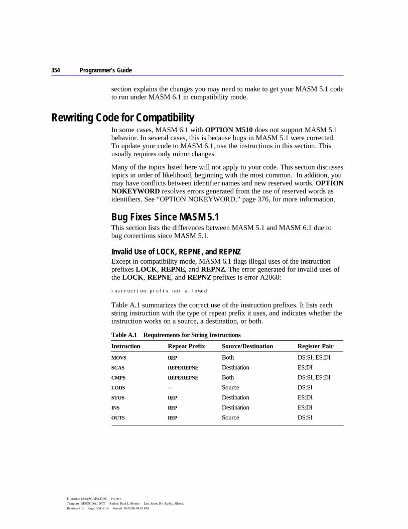
354 Programmer’s Guide
Filename: LMAPGAPA.DOC Project: Template: MSGRIDA1.DOT Author: Ruth L Silverio Last Saved By: Ruth L Silverio Revision #: 2 Page: 354 of 14 Printed: 10/02/00 04:18 PM
section explains the changes you may need to make to get your MASM 5.1 code to run under MASM 6.1 in compatibility mode.
Rewriting Code for Compatibility In some cases, MASM 6.1 with OPTION M510 does not support MASM 5.1 behavior. In several cases, this is because bugs in MASM 5.1 were corrected. To update your code to MASM 6.1, use the instructions in this section. This usually requires only minor changes.
Many of the topics listed here will not apply to your code. This section discusses topics in order of likelihood, beginning with the most common. In addition, you may have conflicts between identifier names and new reserved words. OPTION NOKEYWORD resolves errors generated from the use of reserved words as identifiers. See “OPTION NOKEYWORD,” page 376, for more information.
Bug Fixes Since MASM 5.1 This section lists the differences between MASM 5.1 and MASM 6.1 due to bug corrections since MASM 5.1.
Invalid Use of LOCK, REPNE, and REPNZ Except in compatibility mode, MASM 6.1 flags illegal uses of the instruction prefixes LOCK, REPNE, and REPNZ. The error generated for invalid uses of the LOCK, REPNE, and REPNZ prefixes is error A2068:
instruction prefix not allowed
Table A.1 summarizes the correct use of the instruction prefixes. It lists each string instruction with the type of repeat prefix it uses, and indicates whether the instruction works on a source, a destination, or both.
Table A.1 Requirements for String Instructions
Instruction Repeat Prefix Source/Destination Register Pair
MOVS REP Both DS:SI, ES:DI SCAS REPE/REPNE Destination ES:DI CMPS REPE/REPNE Both DS:SI, ES:DI LODS -- Source DS:SI STOS REP Destination ES:DI INS REP Destination ES:DI OUTS REP Source DS:SI
Appendix A Differences Between MASM 6.1 and 5.1 355
Filename: LMAPGAPA.DOC Project: Template: MSGRIDA1.DOT Author: Ruth L Silverio Last Saved By: Ruth L Silverio Revision #: 2 Page: 355 of 15 Printed: 10/02/00 04:18 PM
No Closing Quotation Marks in Macro Arguments In MASM 5.1, you can use both single and double quotation marks (' and ") to begin strings in macro arguments. The assembler does not generate an error or warning if the string does not end with quotation marks on a macro call. Instead, MASM 5.1 considers the remainder of the line to be part of the macro argument containing the opening quote, as if there were a closing quotation mark at the end of the line.
By default, MASM 6.1 now generates error A2046:
missing single or double quotation mark in string
so all single and double quotation marks in macro arguments must be matched.
To correct such errors in MASM 6.1, either end the string with a closing quotation mark as shown in the following example, or use the macro escape character (!) to treat the quotation mark literally.
; MASM 5.1 code MyMacro "all this in one argument ; Default MASM 6.1 code MyMacro "all this in one argument"
Making a Scoped Label Public MASM 5.1 considers code labels defined with a single colon inside a procedure to be local to that procedure if the module contains a .MODEL directive with a language type. Although the label is local, MASM 5.1 does not generate an error if it is also declared PUBLIC. MASM 6.1 generates error A2203:
cannot declare scoped code label as PUBLIC
If you want to make a label PUBLIC, it must not be local. You can use the double colon operator to define a non-scoped label, as shown in this example:
PUBLIC publicLabel publicLabel:: ; Non-scoped label MASM 6.1
Byte Form of BT, BTS, BTC, and BTR Instructions MASM 5.1 allows a byte argument for the 80386 bit-test instructions, but encodes it as a word argument. The byte form is not supported by the processor.
MASM 6.1 does not support this behavior and generates error A2024:
invalid operand size for instruction
Rewrite your code to use a word-sized argument.

356 Programmer’s Guide
Filename: LMAPGAPA.DOC Project: Template: MSGRIDA1.DOT Author: Ruth L Silverio Last Saved By: Ruth L Silverio Revision #: 2 Page: 356 of 16 Printed: 10/02/00 04:18 PM
Default Values for Record Fields In MASM 5.1, default values for record fields can range down to –2n, where n is the number of bits in the field. This results in the loss of the sign bit.
MASM 6.1 allows a range of –2n–1 to 2n–1 for default values. Illegal initializers generate error A2071:
initializer too large for specified size
Design Change Issues MASM 6.1 includes design changes that make the language more consistent. These changes are not affected by the OPTION directive, discussed later in this appendix. Therefore, the changes require revisions in your code. In most cases, the necessary revisions are minor and the circumstances requiring changes are rare.
Operands of Different Size MASM 5.1 does not require operands to agree in size, as the following code illustrates:
.DATA? var1 DB ? var2 DB ? .CODE . . . mov var1, ax ; Copy AX to word at var1
The operands for the MOV instruction do not match in size, yet the instruction assembles correctly. It places the contents of AL into var1 and AH into var2, moving a word of data in one step. If the code defined var1 as a word value, the instruction
mov var1, al
would also assemble correctly, copying AL into the low byte of var1 while leaving the high byte unaffected. Except at warning level 0, MASM 5.1 issues a warning to inform you of the size mismatch, but both scenarios are legal.
MASM 6.1 does not accept instructions with operands that do not agree in size. You must specifically “coerce” the size of the memory operand, like this:

Appendix A Differences Between MASM 6.1 and 5.1 357
Filename: LMAPGAPA.DOC Project: Template: MSGRIDA1.DOT Author: Ruth L Silverio Last Saved By: Ruth L Silverio Revision #: 2 Page: 357 of 17 Printed: 10/02/00 04:18 PM
mov BYTE PTR var1, al
Conflicting Structure Declarations MASM 5.1 allows you to declare two or more structures with the same name. Each declaration replaces the previous declaration. However, the field names from previous declarations still remain in the assembler’s list of declared values.
MASM 6.1 does not allow conflicting declarations of a structure. It generates errors A2160 through A2165 for each conflicting declaration. The errors note a specific conflict, such as conflicting number of fields, conflicting names of fields, or conflicting initializers.
Forward References to Text Macros Outside of Expressions MASM 5.1 allows forward references to text macros in specialized cases. MASM 6.1 with OPTION M510 also permits forward references, but only when the text macro is referenced in an expression. To revise your code, place all macro definitions at the beginning of the file.
HIGH and LOW Applied to Relocatable Operands In some cases, MASM 5.1 accepts HIGH and LOW applied to relocatable memory expressions. For example, MASM 5.1 allows this code sequence:
; MASM 5.1 code EXTRN var1:WORD var2 DW 0 mov al, LOW var1 ; These two instructions yield the mov ah, HIGH var1 ; same as mov ax, OFFSET var1
However, the instruction
mov ax, LOW var2
is not legal. MASM 6.1 generates error A2105:
HIGH and LOW require immediate operands
The OFFSET operator is required on these operands in MASM 6.1, as shown in the following. Rewrite your code if necessary.
; MASM 6.1 code mov al, LOW OFFSET var1 mov ah, HIGH OFFSET var2
OFFSET Applied to Group Names and Indirect Memory Operands In MASM 6.1, you cannot apply OFFSET to a group name, indirect argument, or procedure argument. Doing so generates error A2098:
358 Programmer’s Guide
Filename: LMAPGAPA.DOC Project: Template: MSGRIDA1.DOT Author: Ruth L Silverio Last Saved By: Ruth L Silverio Revision #: 2 Page: 358 of 18 Printed: 10/02/00 04:18 PM
invalid operand for OFFSET
LENGTH Operator Applied to Record Types In MASM 5.1, the LENGTH operator, when applied to a record type, returns the total number of bits in a record definition.

Appendix A Differences Between MASM 6.1 and 5.1 359
Filename: LMAPGAPA.DOC Project: Template: MSGRIDA1.DOT Author: Ruth L Silverio Last Saved By: Ruth L Silverio Revision #: 2 Page: 359 of 19 Printed: 10/02/00 04:18 PM
In MASM 6.1, the statement LENGTH recordName returns error A2143:
expected data label
Rewrite your code if necessary. The new SIZEOF operator returns information about records in MASM 6.1. For more information, see “Defining Record Variables” in Chapter 5.
Signed Comparison of Hexadecimal Values Using GT, GE, LE, or LT The rules for two’s-complement comparisons have changed. In MASM 5.1, the expression
0FFFFh GT -1
is false because the two’s-complement values are equal. However, because hexadecimal numbers are now treated as unsigned, the expression is true in MASM 6.1. To update, rewrite the affected code.
RET Used with a Constant in Procedures with Epilogues By default in MASM 6.1, the RET instruction followed by a constant suppresses automatic generation of epilogue code. MASM 5.1 ignores the operand and generates the epilogue. Remove the argument if necessary. See “Generating Prologue and Epilogue Code” in Chapter 7.
Code Labels at Top of Procedures with Prologues By default in MASM 5.1, a code label defined on the same line as the first procedure instruction refers to the first byte of the prologue.
In MASM 6.1, a code label defined at the beginning of a procedure refers to the first byte of the procedure after the prologue. If you need to label the start of the prologue code, place the label before the PROC statement. For more information, see “Generating Prologue and Epilogue Code” in Chapter 7.
Use of % as an Identifier Character MASM 5.1 allows % as an identifier character. This behavior leads to ambiguities when % is used as the expansion operator in macros. Since % is not allowed as a character in MASM 6.1 identifiers, you must change the names of any identifiers containing the % character. For a list of legal identifier characters, see “Identifiers” in Chapter 1.
ASSUME CS Set to Wrong Value With MASM 6.1 you do not need to use the ASSUME statement for the CS register. Instead, MASM 6.1 generates an automatic ASSUME statement for the code segment register to the current segment or group, as explained in “Setting the ASSUME Directive for Segment Registers” in Chapter 2.
360 Programmer’s Guide
Filename: LMAPGAPA.DOC Project: Template: MSGRIDA1.DOT Author: Ruth L Silverio Last Saved By: Ruth L Silverio Revision #: 2 Page: 360 of 20 Printed: 10/02/00 04:18 PM
Additionally, MASM 6.1 does not allow explicit ASSUME statements for CS that contradict the automatically set ASSUME statement.
MASM 5.1 allows CS to be assumed to the current segment, even if that segment is a member of a group. With MASM 6.1, this results in warning A4004:
cannot ASSUME CS
To avoid this warning with MASM 6.1, delete the ASSUME statement for CS.
Code Requiring Two-Pass Assembly Unlike version 5.1, MASM 6.1 does most of its work on its first pass, then performs as many subsequent passes as necessary. In contrast, MASM 5.1 always assembles in two source passes. As a result, you may need to revise or delete some pass-dependent constructs under MASM 6.1.
Two-Pass Directives To assure compatibility, MASM 6.1 supports 5.1 directives referring to two passes. These include .ERR1, .ERR2, IF1, IF2, ELSEIF1, and ELSEIF2. For second-pass constructs, you must specify OPTION SETIF2, as discussed in “OPTION SETIF2,” page 377. Without OPTION SETIF2, the IF2 and .ERR2 directives cause error A2061:
[[ELSE]]IF2/.ERR2 not allowed : single-pass assembler
MASM 6.1 handles first-pass constructs differently. It treats the .ERR1 directive as .ERR, and the IF1 directive as IF.
The following examples show you how you can rewrite typical pass-sensitive code for MASM 6.1:
u Declare var external only if not defined in current module: ; MASM 5.1: IF2 IFNDEF var EXTRN var:far ENDIF ENDIF ; MASM 6.1: EXTERNDEF var:far
Appendix A Differences Between MASM 6.1 and 5.1 361
Filename: LMAPGAPA.DOC Project: Template: MSGRIDA1.DOT Author: Ruth L Silverio Last Saved By: Ruth L Silverio Revision #: 2 Page: 361 of 21 Printed: 10/02/00 04:18 PM
u Include a file of definitions only once to speed assembly: ; MASM 5.1: IF1 INCLUDE file1.inc ENDIF ; MASM 6.1: INCLUDE FILE1.INC
u Generate a %OUT or .ERR message only once: ; MASM 5.1: IF2 %OUT This is my message ENDIF IF2 .ERRNZ A NE B ENDIF ; MASM 6.1: ECHO This is my message .ERRNZ A NE B <ASSERTION FAILURE: A NE B>
u Generate an error if a symbol is not defined but may be forward referenced: ; MASM 5.1: IF2 .ERRNDEF var ENDIF ; MASM 6.1: .ERRNDEF var
For information on conditional directives, see “Conditional Directives,” Chapter 1.
IFDEF and IFNDEF with Forward-Referenced Identifiers If you use a symbol name that has not yet been defined in an IFDEF or IFNDEF expression, MASM 6.1 returns FALSE for the IFDEF expression and TRUE for the IFNDEF expression. When OPTION M510 is enabled, the assembler generates warning A6005:
expression condition may be pass-dependent
To resolve the warning, place the symbol definition before the conditional test.

362 Programmer’s Guide
Filename: LMAPGAPA.DOC Project: Template: MSGRIDA1.DOT Author: Ruth L Silverio Last Saved By: Ruth L Silverio Revision #: 2 Page: 362 of 22 Printed: 10/02/00 04:18 PM
Address Spans as Constants The value of offsets calculated on the first assembly pass may not be the same as those calculated on later passes. Therefore, you should avoid comparisons with an address span, as in the following examples:
IF (OFFSET var1 - OFFSET var2) EQ 10 WHILE dx LT (OFFSET var1 - OFFSET var2) REPEAT OFFSET var1 - OFFSET var2
However, the DUP operator allows such an expression as its count value. The assembler evaluates the DUP count on every pass, so even expressions involving forward references assemble correctly.
You can also use expressions containing span distances with the .ERR directives, since the assembler evaluates these directives after calculating all offsets:
.ERRE OFFSET var1 - OFFSET var2 - 10, <span incorrect>
.TYPE with Forward References MASM 5.1 evaluates .TYPE on both assembly passes. This means it yields zero on the first pass and nonzero on the second pass, if applied to an expression that forward-references a symbol.
MASM 6.1 evaluates .TYPE only on the first assembly pass. As a result, if the operand references a symbol that has not yet been defined, .TYPE yields a value of zero. This means that .TYPE, if used in a conditional-assembly construction, may yield different results in MASM 6.1 than in MASM 5.1.
Obsolete Features No Longer Supported The following two features are no longer supported by MASM 6.1. Because both are obscure features provided by early versions of the assembler, they probably do not affect your MASM 5.1 code.
The ESC Instruction MASM 6.1 no longer supports the ESC instruction, which was used to send hand-coded commands to the coprocessor. Because MASM 6.1 recognizes and assembles the full set of coprocessor mnemonics, the ESC instruction is not necessary. Using the ESC instruction generates error A2205:
ESC instruction is obsolete: ignored
To update MASM 5.1 code, use the coprocessor instructions instead of ESC.
Appendix A Differences Between MASM 6.1 and 5.1 363
Filename: LMAPGAPA.DOC Project: Template: MSGRIDA1.DOT Author: Ruth L Silverio Last Saved By: Ruth L Silverio Revision #: 2 Page: 363 of 23 Printed: 10/02/00 04:18 PM
The MSFLOAT Binary Format MASM 6.1 does not support the .MSFLOAT directive, which provided the Microsoft Binary Format (MSB) for floating-point numbers in variable initializers. Using the .MSFLOAT directive generates error A2204:
.MSFLOAT directive is obsolete: ignored
Use IEEE format or, if MSB format is necessary, initialize variables with hexadecimal values. See “Storing Numbers in Floating-Point Format” in Chapter 6.
Using the OPTION Directive The OPTION directive lets you control compatibility with MASM 5.1 code. This section explains the differences in MASM 5.1 and MASM 6.1 behavior that the OPTION directive can influence.
The OPTION M510 directive (or /Zm command-line option) initiates all aspects of 5.1 compatibility mode. You can select from among specific characteristics of MASM 5.1 behavior with the OPTION arguments discussed in following sections. Each section also explains how to revise your code if you want to remove OPTION directives from your MASM 5.1 code.
If your code includes both .MODEL and OPTION M510, the OPTION M510 statement must appear first. Wherever this appendix suggests using OPTION M510 in your code, you can set the /Zm command-line option instead.
OPTION M510 This section discusses the M510 argument to the OPTION directive, which selects the MASM 5.1 compatibility mode. In this mode, MASM 6.1 implements MASM 5.1 behavior relating to macros, offsets, scope of code labels, structures, identifier names, identifier case, and other behaviors.
The OPTION M510 directive automatically sets the following:
OPTION OLDSTRUCTS ; MASM 5.1 structures OPTION OLDMACROS ; MASM 5.1 macros OPTION DOTNAME ; Identifiers may begin with a dot (.) OPTION SETIF2:TRUE ; Two-pass code activates on every pass
If you do not have a .386, 386P .486, or 486P directive in your module, then OPTION M510 adds:
Note
364 Programmer’s Guide
Filename: LMAPGAPA.DOC Project: Template: MSGRIDA1.DOT Author: Ruth L Silverio Last Saved By: Ruth L Silverio Revision #: 2 Page: 364 of 24 Printed: 10/02/00 04:18 PM
OPTION EXPR16 ; 16-bit expression precision ; See "OPTION EXPR16," following
Appendix A Differences Between MASM 6.1 and 5.1 365
Filename: LMAPGAPA.DOC Project: Template: MSGRIDA1.DOT Author: Ruth L Silverio Last Saved By: Ruth L Silverio Revision #: 2 Page: 365 of 25 Printed: 10/02/00 04:18 PM
If you do not have a .MODEL directive in your module, OPTION M510 adds:
OPTION OFFSET:SEGMENT ; OFFSET operator defaults to ; segment-relative ; See "OPTION OFFSET," following
If you do not have a .MODEL directive with a language specifier in your module, OPTION M510 also adds:
OPTION NOSCOPED ; Code labels are not local inside ; procedures ; See "OPTION NOSCOPED," following OPTION PROC:PRIVATE ; Labels defined with PROC are not ; public by default ; See "OPTION PROC," following
If you want to remove OPTION M510 from your code (or /Zm from the command line), add the OPTION directive arguments to your module according to the conditions stated earlier.
There may be compatibility issues affecting your code that are supported under OPTION M510, but are not covered by the other OPTION directive arguments. Once you have modified your source code so it no longer requires behavior supported by OPTION M510, you can replace OPTION M510 with other OPTION directive arguments. These compatibility issues are discussed in following sections.
Once you have replaced OPTION M510 with other forms of the OPTION directive and your code works correctly, try removing the OPTION directives, one at a time. Make appropriate source modifications as necessary, until your code uses only MASM 6.1 defaults.
Reserved Keywords Dependent on CPU Mode with OPTION M510 With OPTION M510, keywords and instructions not available in the current CPU mode (such as ENTER under .8086) are not treated as keywords. This also means the USE32, FLAT, FAR32, and NEAR32 segment types and the 80386/486 registers are not keywords with a processor selection less than .386.
If you remove OPTION M510, any reserved word used as an identifier generates a syntax error. You can either rename the identifiers or use OPTION NOKEYWORD. For more information on OPTION NOKEYWORD, see “OPTION NOKEYWORD,” later in this appendix.
Invalid Use of Instruction Prefixes with OPTION M510 Code without OPTION M510 generates errors for all invalid uses of the instruction prefixes. OPTION M510 suppresses some of these errors to match MASM 5.1 behavior. MASM 5.1 does not check for illegal usage of the instruction prefixes LOCK, REP, REPE, REPZ, REPNE, and REPNZ.
366 Programmer’s Guide
Filename: LMAPGAPA.DOC Project: Template: MSGRIDA1.DOT Author: Ruth L Silverio Last Saved By: Ruth L Silverio Revision #: 2 Page: 366 of 26 Printed: 10/02/00 04:18 PM
Illegal usage of these prefixes results in error A2068:
instruction prefix not allowed
For more information on these instruction prefixes, see “Overview of String Instructions” in Chapter 5. See also “Bug Fixes from MASM 5.1,” earlier in this appendix.
Size of Constant Operands with OPTION M510 In MASM 5.1, a large constant value that can fit only in the processor’s default word (4 bytes for .386 and .486, 2 bytes otherwise) is assigned a size attribute of the default word size. The value of the constant affects the number of bytes changed by the instruction. For example,
; Legal only with OPTION M510 mov [bx], 0100h
is legal in OPTION M510 mode. Since 0100h cannot fit in a byte, the assembler interprets the value as a word.
Without OPTION M510, the assembler never assigns a size automatically. You must state it explicitly with the PTR operator, as shown in the following example:
; Without OPTION M510 mov [bx], WORD PTR 0100h
Code Labels when Defining Data with OPTION M510 MASM 5.1 allows a code label definition in a data definition statement if that statement does not also define a data label. MASM 6.1 also allows such definitions if OPTION M510 is enabled; otherwise it is illegal.
; Legal only with OPTION M510 MyCodeLabel: DW 0
SEG Operator with OPTION M510 In MASM 5.1, the SEG operator returns a label’s segment address unless the frame is explicitly specified, in which case it returns the segment address of the frame. A statement such as SEG DGROUP:var always returns DGROUP, whereas SEG var always returns the segment address of var. OPTION M510 forces this same behavior in MASM 6.1.
If you do not use OPTION M510, the behavior of the SEG operator is determined by the OPTION OFFSET directive, as described in “OPTION OFFSET,” later in this appendix.
In MASM 6.1, the value returned by the SEG operator applied to a nonexternal variable depends on compatibility mode:

Appendix A Differences Between MASM 6.1 and 5.1 367
Filename: LMAPGAPA.DOC Project: Template: MSGRIDA1.DOT Author: Ruth L Silverio Last Saved By: Ruth L Silverio Revision #: 2 Page: 367 of 27 Printed: 10/02/00 04:18 PM
u Without OPTION M510, SEG returns the address of the frame (the segment, group, or the value assumed to the segment register) if one has been explicitly set.
u With OPTION M510, SEG returns the group if one has been specified. In the absence of a defined group, SEG returns the segment where the variable is defined.
Expression Evaluation with OPTION M510 By default, MASM 6.1 changes the way expressions are evaluated. In MASM 5.1,
var-2[bx]
is parsed as
(var-2)[bx]
Without OPTION M510, you must rewrite the statement, since the assembler parses it as
var-(2[bx])
which generates an error.
Length and Size of Labels with OPTION M510 With OPTION M510, you can apply the LENGTH and SIZE operators to any label. For a code label, SIZE returns a value of 0FFFFh for NEAR and 0FFFEh for FAR. LENGTH always returns a value of 1. For strings, SIZE and LENGTH both return 1.
Without OPTION M510, SIZE returns values of 0FF01h, 0FF02h, 0FF04h, 0FF05h, and 0FF06h for SHORT, NEAR16, NEAR32, FAR16, and FAR32 labels, respectively. LENGTH returns 1 except when used with DUP, in which case it returns the outermost count. For arrays initialized with DUP, SIZE returns the length multiplied by the size of the type.
The LENGTHOF and SIZEOF operators in MASM 6.1 handle arrays much more consistently. These operators return the number of data items and the number of bytes in an initializer. For a description of SIZEOF and LENGTHOF, see the following sections in Chapter 5: “Declaring and Referencing Arrays,” “Declaring and Initializing Strings,” “Defining Structure and Union Variables,” and “Defining Record Variables.”
Comparing Types Using EQ and NE with OPTION M510 With OPTION M510, the assembler converts types to a constant value before comparisons with EQ and NE. Code types are converted to values of 0FFFFh

368 Programmer’s Guide
Filename: LMAPGAPA.DOC Project: Template: MSGRIDA1.DOT Author: Ruth L Silverio Last Saved By: Ruth L Silverio Revision #: 2 Page: 368 of 28 Printed: 10/02/00 04:18 PM
(near) or 0FFFEh (far). If OPTION M510 is not enabled, the assembler converts types to constants only when comparing them with constants. Thus, MASM 6.1 recognizes only equivalent qualified types as equal expressions.
For existing MASM 5.1 code, these distinctions affect only the use of the TYPE operator in conjunction with EQ and NE. The following example illustrates how the assembler compares types with and without compatibility mode:
MYSTRUCT STRUC f1 DB 0 f2 DB 0 MYSTRUCT ENDS ; With OPTION M510 val = (TYPE MYSTRUCT) EQ WORD ; True: 2 EQ 2 val = 2 EQ WORD ; True: 2 EQ 2 val = WORD EQ WORD ; True: 2 EQ 2 val = SWORD EQ WORD ; True: 2 EQ 2 ; Without OPTION M510 val = (TYPE MYSTRUCT) EQ WORD ; False: MyStruct NE WORD val = 2 EQ WORD ; True: 2 EQ 2 val = WORD EQ WORD ; True: WORD EQ WORD val = SWORD EQ WORD ; False: SWORD NE WORD
Use of Constant and PTR as a Type with OPTION M510 You can use a constant as the left operand to PTR in compatibility mode. Otherwise, you must use a type expression. With OPTION M510, a constant must have a value of 1 (BYTE), 2 (WORD), 4 (DWORD), 6 (FWORD), 8 (QWORD) or 10 (TBYTE). The assembler treats the constant as the

Appendix A Differences Between MASM 6.1 and 5.1 369
Filename: LMAPGAPA.DOC Project: Template: MSGRIDA1.DOT Author: Ruth L Silverio Last Saved By: Ruth L Silverio Revision #: 2 Page: 369 of 29 Printed: 10/02/00 04:18 PM
parenthesized type. Note that the TYPE operator yields a type expression, but the SIZE operator yields a constant.
; With OPTION M510 MyData DW 0 mov WORD PTR [bx], 10 ; Legal mov (TYPE MyData) PTR [bx], 10 ; Legal mov (SIZE MyData) PTR [bx], 10 ; Legal mov 2 ptr [bx], 10 ; Legal ; Without OPTION M510 MyData WORD 0 mov WORD PTR [bx], 10 ; Legal mov (TYPE MyData) PTR [bx], 10 ; Legal ; mov (SIZE MyData) PTR [bx], 10 ; Illegal ; mov 2 PTR [bx], 10 ; Illegal
Structure Type Cast on Expressions with OPTION M510 In compatibility mode, use the PTR operator to type-cast a constant to a structure type. This is most often done in data initializers to affect the CodeView information of the data label. Without OPTION M510, the assembler generates an error.
MYSTRC STRUC f1 DB 0 MYSTRC ENDS MyPtr DW MYSTRC PTR 0 ; Illegal without OPTION M510
In MASM 6.1, the initializer type does not influence CodeView’s type information.
Hidden Coercion of OFFSET Expression Size with OPTION M510 When programming for the 80386 or 80486, the size of an OFFSET expression can be 2 bytes for a symbol in a USE16 segment, or 4 bytes for a symbol in a USE32 or FLAT segment. With OPTION M510, you can use a 32-bit OFFSET expression in a 16-bit context. Without OPTION M510, you must use the LOWWORD operator to convert the offset size.
370 Programmer’s Guide
Filename: LMAPGAPA.DOC Project: Template: MSGRIDA1.DOT Author: Ruth L Silverio Last Saved By: Ruth L Silverio Revision #: 2 Page: 370 of 30 Printed: 10/02/00 04:18 PM
.386 ; With OPTION M510 seg32 SEGMENT USE32 MyLabel WORD 0 seg32 ENDS seg16 SEGMENT USE16 'code' ; With OPTION M510: mov ax, OFFSET MyLabel ; Legal mov ax, LOWWORD OFFSET MyLabel ; Legal mov eax, OFFSET MyLabel ; Legal seg16 ENDS ; Without OPTION M510 seg32 SEGMENT USE32 MyLabel WORD 0 seg32 ENDS seg16 SEGMENT USE16 'code' ; Without OPTION M510: ; mov ax, OFFSET MyLabel ; Illegal mov ax, LOWWORD offset MyLabel ; Legal mov eax, OFFSET MyLabel ; Legal seg16 ENDS
Specifying Radixes with OPTION M510 If the current radix in your code is greater than 10 decimal, MASM 6.1 allows the radix specifiers B (binary) and D (decimal) only in compatibility mode. You must change B to Y for binary, and D to T for decimal, since both B and D are legitimate hexadecimal values, making numbers such as 12D ambiguous. If you want to keep B and D as radix specifiers when the current radix is greater than 10, you must specify OPTION M510. For more information about radixes, see “Integer Constants and Constant Expressions” in Chapter 1.
Naming Conventions with OPTION M510 By default, MASM 5.1 does not write the names of public variables in uppercase to the object file, even when a language type of PASCAL, FORTRAN, or BASIC is specified.
Unless you use OPTION M510, these language types in MASM 6.1 write identifier names in uppercase, even with the /Cp or /Cx command-line options. When you link with /NOI, case must match in the object files to resolve externals.
Appendix A Differences Between MASM 6.1 and 5.1 371
Filename: LMAPGAPA.DOC Project: Template: MSGRIDA1.DOT Author: Ruth L Silverio Last Saved By: Ruth L Silverio Revision #: 2 Page: 371 of 31 Printed: 10/02/00 04:18 PM
Length Significance of Symbol Names with OPTION M510 With MASM 5.1, only the first 31 characters of a symbol name are considered significant, and only the first 31 characters of a public or external symbol name are placed in the object file.
Without OPTION M510, the entire name is considered significant. The maximum number of characters placed in the object file is controlled with the /Hnumber command-line option, with a default of 247 (the maximum length of an identifier in MASM 6.1).
String Defaults in Structure Variables with OPTION M510 In compatibility mode, a constant initializer can override a structure field initialized with a string value. Without OPTION M510, only another string or a list can override a string initializer. To update your code, surround the constant override value with angle brackets or curly braces to indicate a list with one element.
MTSTRUCT STRUCT MyString BYTE "This is a string" MTSTRUCT ENDS ; With OPTION M510 MyInst MTSTRUCT <0> ; Without OPTION M510, either of these statements is correct MyInst MTSTRUCT <<0>> MyInst MTSTRUCT {<0>}
Effects of the ? Initializer in Data Definitions with OPTION M510 As described in “Declaring and Initializing Strings” in Chapter 5, the assembler treats the ? initializer as either zero or as an unspecified value. In compatibility mode, however, the assembler always treats the ? initializer as zero unless it is used with the DUP operator. In this case, the assembler allocates space, but does not initialize it with any value.
Current Address Operator with OPTION M510 In compatibility mode, the current address operator ($) applied to a structure returns the offset of the first byte of the structure. When OPTION M510 is not enabled, $ returns the offset of the current field in the structure.
Segment Association for FAR Externals with OPTION M510 In MASM 5.1, you must place an EXTRN directive for a variable in the same segment that holds the variable. For far data, this often entails opening and closing a segment just to place the EXTRN statement.

372 Programmer’s Guide
Filename: LMAPGAPA.DOC Project: Template: MSGRIDA1.DOT Author: Ruth L Silverio Last Saved By: Ruth L Silverio Revision #: 2 Page: 372 of 32 Printed: 10/02/00 04:18 PM
MASM 6.1 offers much greater flexibility in where EXTERN and EXTERNDEF statements can appear, as described in “Positioning External Declarations” in Chapter 8. However, in compatibility mode, MASM 6.1 emulates the behavior of MASM 5.1.
Defining Aliases Using EQU with OPTION M510 In MASM 5.1, you can equate one symbol with another. These equates are called “aliases.”
Unless you specify OPTION M510, MASM 6.1 does not allow aliases defined with EQU. An immediate expression or text must appear as the right operand of an EQU directive. Change aliases to use the TEXTEQU directive, described in “Text Macros” in Chapter 9. This change may cause an expression to evaluate differently.
The following examples illustrate the differences between MASM 5.1 code, MASM 6.1 code with OPTION M510, and MASM 6.1 code without OPTION M510:
; MASM 5.1 code var1 EQU 3 var2 EQU var1 ; var2 taken as an alias ; var2 references var1 anywhere var2 is ; used as a symbol ; MASM 6.1 with OPTION M510 var1 EQU 3 var2 EQU var1 ; var2 taken as a var2 EQU <var1> ; var2 substituted for var1 whenever ; text macros substituted ; MASM 6.1 without OPTION M510 var1 EQU 3 var2 EQU var1 ; Treated as var2 EQU 3

Appendix A Differences Between MASM 6.1 and 5.1 373
Filename: LMAPGAPA.DOC Project: Template: MSGRIDA1.DOT Author: Ruth L Silverio Last Saved By: Ruth L Silverio Revision #: 2 Page: 373 of 33 Printed: 10/02/00 04:18 PM
Difference in Text Macro Expansions with OPTION M510 MASM 6.1 recursively expands text macros used as values, whereas MASM 5.1 simply replaces the text macro with its value. The following example illustrates the difference:
; With OPTION M510 tm1 EQU <contains tm2> tm2 EQU <value> tm3 CATSTR tm1 ; == <contains tm2> ; Without OPTION M510 tm3 CATSTR tm1 ; == <contains value>
Conditional Directives and Missing Operands with OPTION M510 MASM 5.1 considers a missing argument to be a zero. MASM 6.1 requires an argument unless OPTION M510 is enabled.
OPTION OLDSTRUCTS This section describes changes in MASM 6.1 that apply to structures. With OPTION OLDSTRUCTS or OPTION M510:
u You can use plus operator (+) in structure field references. u Labels and structure field names cannot have the same name with OPTION
OLDSTRUCTS.
Plus Operator Not Allowed with Structures By default, each reference to structure member names must use the dot operator (.) to separate the structure variable name from the field name. You cannot use the dot operator as the plus operator (+) or vice versa.
To convert your code so that it does not need OPTION OLDSTRUCTS:
u Qualify all structure field references. u Change all uses of the dot operator ( . ) that occur outside of structure
references to use the plus operator ( + ).
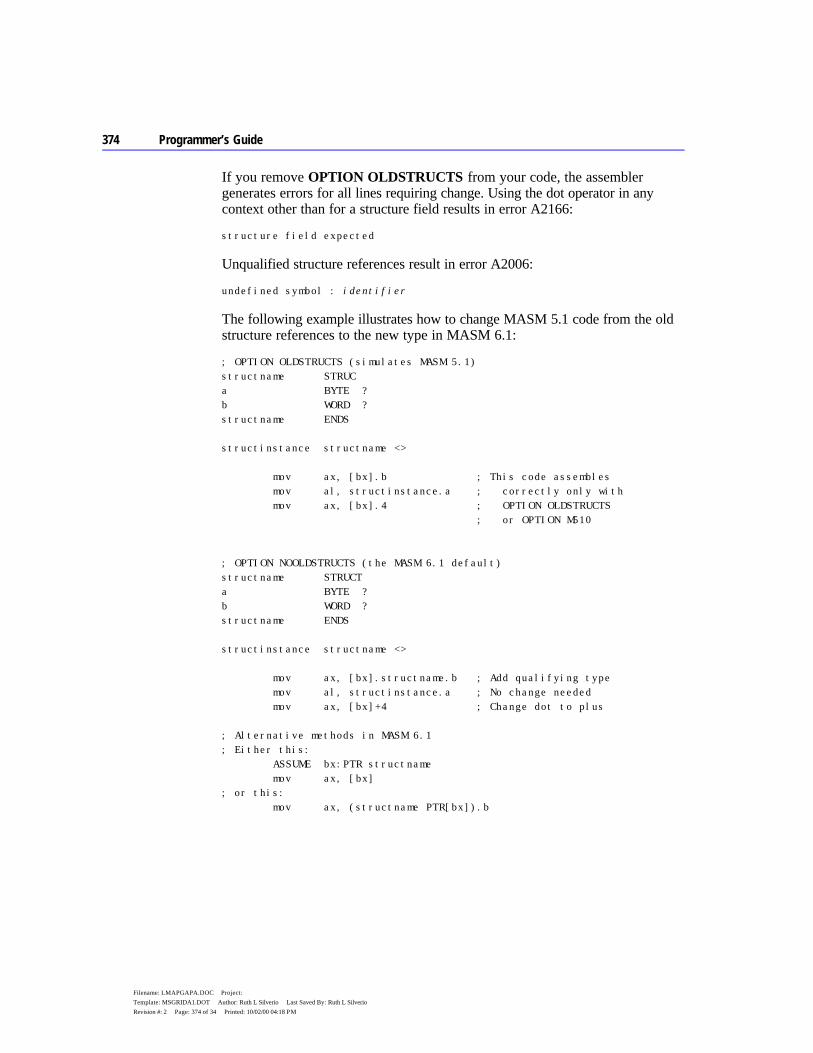
374 Programmer’s Guide
Filename: LMAPGAPA.DOC Project: Template: MSGRIDA1.DOT Author: Ruth L Silverio Last Saved By: Ruth L Silverio Revision #: 2 Page: 374 of 34 Printed: 10/02/00 04:18 PM
If you remove OPTION OLDSTRUCTS from your code, the assembler generates errors for all lines requiring change. Using the dot operator in any context other than for a structure field results in error A2166:
structure field expected
Unqualified structure references result in error A2006:
undefined symbol : identifier
The following example illustrates how to change MASM 5.1 code from the old structure references to the new type in MASM 6.1:
; OPTION OLDSTRUCTS (simulates MASM 5.1) structname STRUC a BYTE ? b WORD ? structname ENDS structinstance structname <> mov ax, [bx].b ; This code assembles mov al, structinstance.a ; correctly only with mov ax, [bx].4 ; OPTION OLDSTRUCTS ; or OPTION M510 ; OPTION NOOLDSTRUCTS (the MASM 6.1 default) structname STRUCT a BYTE ? b WORD ? structname ENDS structinstance structname <> mov ax, [bx].structname.b ; Add qualifying type mov al, structinstance.a ; No change needed mov ax, [bx]+4 ; Change dot to plus ; Alternative methods in MASM 6.1 ; Either this: ASSUME bx:PTR structname mov ax, [bx] ; or this: mov ax, (structname PTR[bx]).b
Appendix A Differences Between MASM 6.1 and 5.1 375
Filename: LMAPGAPA.DOC Project: Template: MSGRIDA1.DOT Author: Ruth L Silverio Last Saved By: Ruth L Silverio Revision #: 2 Page: 375 of 35 Printed: 10/02/00 04:18 PM
Duplicate Structure Field Names With the default, OPTION NOOLDSTRUCTS, label and structure field names may have the same name. With OPTION OLDSTRUCTS (the MASM 5.1 default), labels and structure fields cannot have the same name. For more information, see “Structures and Unions” in Chapter 5.
OPTION OLDMACROS This section describes how MASM 5.1 and 6.1 differ in their handling of macros. Without OPTION OLDMACROS or OPTION M510, MASM 6.1 changes the behavior of macros in several ways. If you want the MASM 5.1 macro behavior, add OPTION OLDMACROS or OPTION M510 to your MASM 5.1 code.
Separating Macro Arguments with Commas MASM 5.1 allows white spaces or commas to separate arguments to macros. MASM 6.1 with OPTION NOOLDMACROS (the default) requires commas between arguments. For example, in the macro call
MyMacro var1 var2 var3, var4
OPTION OLDMACROS causes the assembler to treat all four items as separate arguments. With OPTION NOOLDMACROS, the assembler treats
var1 var2 var3
as one argument, since the items are not separated with commas. To convert your macro code, replace spaces between macro arguments with a single comma.
New Behavior with Ampersands in Macros The default OPTION NOOLDMACROS causes the assembler to interpret ampersands (&) within a macro differently than does MASM 5.1. MASM 5.1 requires one ampersand for each level of macro nesting. OPTION OLDMACROS emulates this behavior.
Without OPTION OLDMACROS, MASM 6.1 removes ampersands only once no matter how deeply nested the macro. To update your MASM 5.1 macros, follow this simple rule: replace every sequence of ampersands with a single ampersand. The only exception is when macro parameters immediately precede and follow the ampersand, and both require substitution. In this case, use two ampersands. For a description of the new rules, see “Substitution Operator” in Chapter 9.

376 Programmer’s Guide
Filename: LMAPGAPA.DOC Project: Template: MSGRIDA1.DOT Author: Ruth L Silverio Last Saved By: Ruth L Silverio Revision #: 2 Page: 376 of 36 Printed: 10/02/00 04:18 PM
This example shows how to update a MASM 5.1 macro:
; OPTION OLDMACROS (emulates MASM 5.1 behavior) createNames macro arg irp tail, <Next, Last> irp num, <1, 2> ; Define more names of the form: abcNext1? arg&&tail&&&num&&&? label BYTE ENDM ENDM ENDM ; OPTION NOOLDMACROS (the MASM 6.1 default) createNames macro arg for tail, <Next, Last> ; FOR is the MASM 6.1 for num, <1, 2> ; synonym for irp ; Define more names of the form: abcNext1? arg&&tail&&num&? label BYTE ENDM ENDM ENDM
OPTION DOTNAME MASM 5.1 allows names of identifiers to begin with a period. The MASM 6.1 default is OPTION NODOTNAME. Adding OPTION DOTNAME to your code enables the MASM 5.1 behavior.
If you don’t want to use this directive in your source code, rename the identifiers whose names begin with a period.
OPTION EXPR16 MASM 5.1 treats expressions as 16-bit words if you do not specify .386 or .386P directives. MASM 6.1 by default treats expressions as 32-bit words, regardless of the CPU type. You can force MASM 6.1 to use the smaller expression size with the OPTION EXPR16 statement.
Unless your MASM 5.1 code specifies .386 or .386P, OPTION M510 also sets 16-bit expression size. You can selectively disable this by following OPTION M510 with the OPTION EXPR32 directive, which sets the size back to 32 bits. You cannot have both OPTION EXPR32 and OPTION EXPR16 in your program.
It may not be easy to determine the effect of changing from 16-bit internal expression size to 32-bit size. In most cases, the 32-bit word size does not affect the MASM 5.1 code. However, problems may arise because of differences in
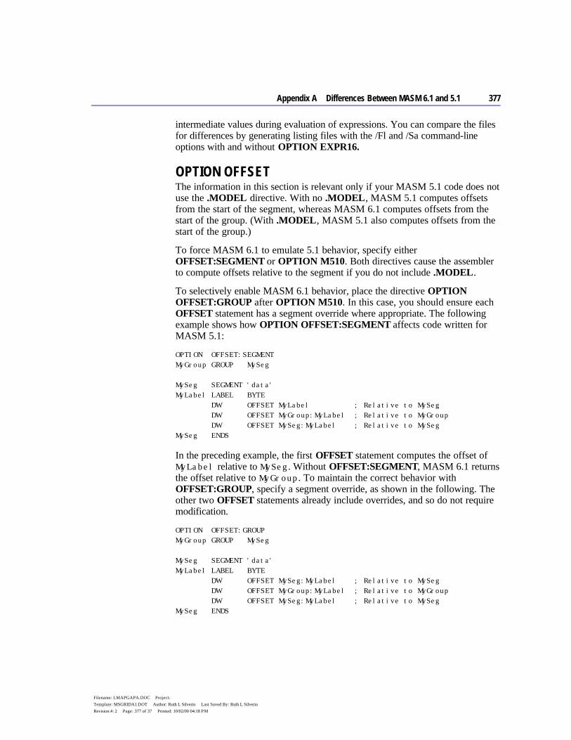
Appendix A Differences Between MASM 6.1 and 5.1 377
Filename: LMAPGAPA.DOC Project: Template: MSGRIDA1.DOT Author: Ruth L Silverio Last Saved By: Ruth L Silverio Revision #: 2 Page: 377 of 37 Printed: 10/02/00 04:18 PM
intermediate values during evaluation of expressions. You can compare the files for differences by generating listing files with the /Fl and /Sa command-line options with and without OPTION EXPR16.
OPTION OFFSET The information in this section is relevant only if your MASM 5.1 code does not use the .MODEL directive. With no .MODEL, MASM 5.1 computes offsets from the start of the segment, whereas MASM 6.1 computes offsets from the start of the group. (With .MODEL, MASM 5.1 also computes offsets from the start of the group.)
To force MASM 6.1 to emulate 5.1 behavior, specify either OFFSET:SEGMENT or OPTION M510. Both directives cause the assembler to compute offsets relative to the segment if you do not include .MODEL.
To selectively enable MASM 6.1 behavior, place the directive OPTION OFFSET:GROUP after OPTION M510. In this case, you should ensure each OFFSET statement has a segment override where appropriate. The following example shows how OPTION OFFSET:SEGMENT affects code written for MASM 5.1:
OPTION OFFSET:SEGMENT MyGroup GROUP MySeg MySeg SEGMENT 'data' MyLabel LABEL BYTE DW OFFSET MyLabel ; Relative to MySeg DW OFFSET MyGroup:MyLabel ; Relative to MyGroup DW OFFSET MySeg:MyLabel ; Relative to MySeg MySeg ENDS
In the preceding example, the first OFFSET statement computes the offset of MyLabel relative to MySeg. Without OFFSET:SEGMENT, MASM 6.1 returns the offset relative to MyGroup. To maintain the correct behavior with OFFSET:GROUP, specify a segment override, as shown in the following. The other two OFFSET statements already include overrides, and so do not require modification.
OPTION OFFSET:GROUP MyGroup GROUP MySeg MySeg SEGMENT 'data' MyLabel LABEL BYTE DW OFFSET MySeg:MyLabel ; Relative to MySeg DW OFFSET MyGroup:MyLabel ; Relative to MyGroup DW OFFSET MySeg:MyLabel ; Relative to MySeg MySeg ENDS
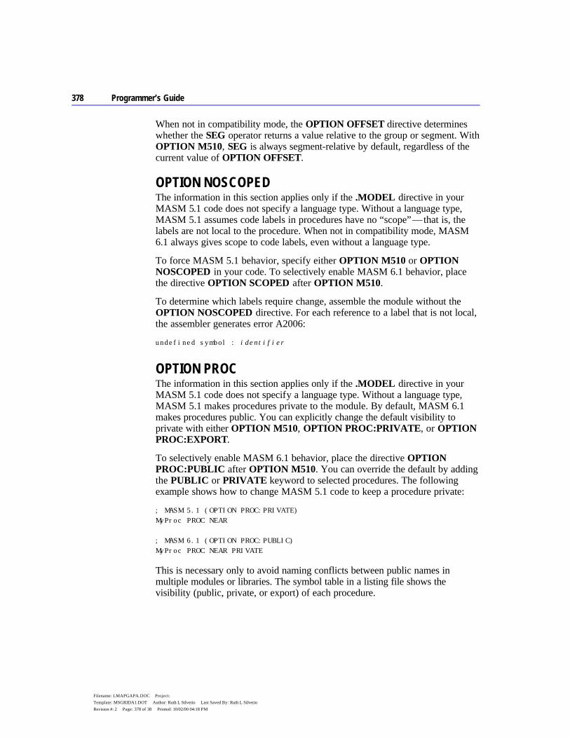
378 Programmer’s Guide
Filename: LMAPGAPA.DOC Project: Template: MSGRIDA1.DOT Author: Ruth L Silverio Last Saved By: Ruth L Silverio Revision #: 2 Page: 378 of 38 Printed: 10/02/00 04:18 PM
When not in compatibility mode, the OPTION OFFSET directive determines whether the SEG operator returns a value relative to the group or segment. With OPTION M510, SEG is always segment-relative by default, regardless of the current value of OPTION OFFSET.
OPTION NOSCOPED The information in this section applies only if the .MODEL directive in your MASM 5.1 code does not specify a language type. Without a language type, MASM 5.1 assumes code labels in procedures have no “scope” — that is, the labels are not local to the procedure. When not in compatibility mode, MASM 6.1 always gives scope to code labels, even without a language type.
To force MASM 5.1 behavior, specify either OPTION M510 or OPTION NOSCOPED in your code. To selectively enable MASM 6.1 behavior, place the directive OPTION SCOPED after OPTION M510.
To determine which labels require change, assemble the module without the OPTION NOSCOPED directive. For each reference to a label that is not local, the assembler generates error A2006:
undefined symbol : identifier
OPTION PROC The information in this section applies only if the .MODEL directive in your MASM 5.1 code does not specify a language type. Without a language type, MASM 5.1 makes procedures private to the module. By default, MASM 6.1 makes procedures public. You can explicitly change the default visibility to private with either OPTION M510, OPTION PROC:PRIVATE, or OPTION PROC:EXPORT.
To selectively enable MASM 6.1 behavior, place the directive OPTION PROC:PUBLIC after OPTION M510. You can override the default by adding the PUBLIC or PRIVATE keyword to selected procedures. The following example shows how to change MASM 5.1 code to keep a procedure private:
; MASM 5.1 (OPTION PROC:PRIVATE) MyProc PROC NEAR ; MASM 6.1 (OPTION PROC:PUBLIC) MyProc PROC NEAR PRIVATE
This is necessary only to avoid naming conflicts between public names in multiple modules or libraries. The symbol table in a listing file shows the visibility (public, private, or export) of each procedure.

Appendix A Differences Between MASM 6.1 and 5.1 379
Filename: LMAPGAPA.DOC Project: Template: MSGRIDA1.DOT Author: Ruth L Silverio Last Saved By: Ruth L Silverio Revision #: 2 Page: 379 of 39 Printed: 10/02/00 04:18 PM
OPTION NOKEYWORD MASM 6.1 has several new keywords that MASM 5.1 does not recognize as reserved. To resolve any conflicts, you can:
u Rename any offending symbols in your code. u Selectively disable keywords with the OPTION NOKEYWORD directive.
The second option lets you retain the offending symbol names in your code by forcing MASM 6.1 to not recognize them as keywords. For example,
OPTION NOKEYWORD:<INVOKE STRUCT>
removes the keywords INVOKE and STRUCT from the assembler’s list of reserved words. However, you cannot then use the keywords in their intended function, since the assembler no longer recognizes them.
The following list shows MASM 6.1 reserved words new since MASM 5.1:
.BREAK
.CONTINUE
.DOSSEG
.ELSE
.ELSEIF
.ENDIF
.ENDW
.EXIT
.IF
.LISTALL
.LISTIF
.LISTMACRO
.LISTMACROALL
.NO87
.NOCREF
.NOLIST
.NOLISTIF
.NOLISTMACRO
.REPEAT
.STARTUP
.UNTIL
.UNTILCXZ
.WHILE
ADDR
ALIAS
BSWAP
CARRY?
CMPXCHG
ECHO
EXTERN
EXTERNDEF
FAR16
FAR32
FLAT
FLDENVD
FLDENVW
FNSAVED
FNSAVEW
FNSTENVD
FNSTENVW
FOR
FORC
FRSTORD
FRSTORW
FSAVED
FSAVEW
FSTENVD
FSTENVW
GOTO
HIGHWORD
INVD
INVLPG
INVOKE
IRETDF
IRETF
LENGTHOF
LOOPD
LOOPED
LOOPEW
LOOPNED
LOOPNEW
LOOPNZD
LOOPNZW

380 Programmer’s Guide
Filename: LMAPGAPA.DOC Project: Template: MSGRIDA1.DOT Author: Ruth L Silverio Last Saved By: Ruth L Silverio Revision #: 2 Page: 380 of 40 Printed: 10/02/00 04:18 PM
LOOPW
LOOPZW
LOWWORD
LROFFSET
NEAR16
NEAR32
OPATTR
OPTION
OVERFLOW?
PARITY?
POPAW
POPCONTEXT
PROTO
PUSHAW
PUSHCONTEXT
PUSHD
PUSHW
REAL10
REAL4
REAL8
REPEAT
SBYTE
SDWORD
SIGN?
SIZEOF
STDCALL
STRUCT
SUBTITLE
SWORD
SYSCALL
TEXTEQU
TR3
TR4
TR5
TYPEDEF
UNION
VARARG
WBINVD
WHILE
XADD
ZERO?
OPTION SETIF2 By default, MASM 6.1 does not recognize pass-dependent constructs. Both the OPTION M510 and OPTION SETIF2 statements force MASM 6.1 to handle MASM 5.1 constructs that activate on the second assembly pass, such as .ERR2, IF2, and ELSEIF2.
Invoke the option like this:
OPTION SETIF2: {TRUE | FALSE}
When set to TRUE, OPTION SETIF2 forces all second-pass constructs to activate on every assembly pass. When set to FALSE, second-pass constructs do not activate on any pass. OPTION M510 implies OPTION SETIF2:TRUE.
Changes to Instruction Encodings MASM 6.1 contains changes to the encodings for several instructions. In some cases, the changes help optimize code size.
Coprocessor Instructions For the 8087 coprocessor, MASM 5.1 adds an extra NOP before the no-wait versions of coprocessor instructions. MASM 6.1 does not. In the rare case that the missing NOP affects timing, insert NOP.
Chapter 1 Chapter Head 381
Filename: LMAPGAPA.DOC Project: Template: MSGRIDA1.DOT Author: Ruth L Silverio Last Saved By: Ruth L Silverio Revision #: 2 Page: 381 of 41 Printed: 10/02/00 04:18 PM
For the 80287 coprocessor or better, MASM 5.1 inserts FWAIT before certain instructions. MASM 6.1 does not prefix any 80287, 80387, or 80486 coprocessor instruction with FWAIT, except for wait forms of instructions that have a no-wait form.
RET Instruction MASM 5.1 generates a 3-byte encoding for RET, RETN, or RETF instructions with an operand value of zero, unless the operand is an external absolute. In this case, MASM 5.1 ignores the parameter and generates a 1-byte encoding.
MASM 6.1 does the opposite. It ignores a zero operand for the return instructions and generates a 1-byte encoding, unless the operand is an external absolute. In this case, MASM 6.1 generates a 3-byte encoding.
Thus, you can suppress epilogue code in a procedure but still specify the default size for RET by coding the return as
ret 0
Arithmetic Instructions Versions 5.1 and 6.1 differ in the way they encode the arithmetic instructions ADC, ADD, AND, CMP, OR, SUB, SBB, and XOR, under the following conditions:
u The first operand is either AX or EAX. u The second operand is a constant value between 0 and 127.
For the AX register, there is no size or speed difference between the two encodings. For the EAX register, the encoding in MASM 6.1 is 2 bytes smaller. The OPTION NOSIGNEXTEND directive forces the MASM 5.1 behavior for AND, OR, and XOR.
379
Filename: LMAPGAPB.DOC Project: Template: MSGRIDA1.DOT Author: Ruth L Silverio Last Saved By: Ruth L Silverio Revision #: 2 Page: 379 of 1 Printed: 10/02/00 04:19 PM
A P P E N D I X B
This appendix provides a complete description of symbols, operators, and directives for MASM 6.1. It uses the Backus-Naur Form (BNF) for grammar notation. You can use BNF grammar to determine the exact syntax for any language component and find all available options for any MASM command.
BNF definitions consist of “nonterminals” and “terminals.” Nonterminals are placeholders within a BNF definition, defined elsewhere in the BNF grammar. Terminals are endpoints in a BNF definition, consisting of MASM 6.1 keywords. In this Appendix, all nonterminals appear in italics type and all terminals appear in bold type.
BNF Conventions The conventions use different font attributes for different items in the BNF. The symbols and formats are as follows:
Attribute Description
nonterminal Italic type indicates nonterminals. RESERVED Terminals in boldface type are literal reserved words and
symbols that must be entered as shown. Characters in this context are always case insensitive.
[[ ]] Objects enclosed in double brackets ([[ ]]) are optional. The brackets do not actually appear in the source code.
| A vertical bar indicates a choice between the items on each side of the bar.
.8086 Underlined items indicate the default option if one is given. default typeface Characters in the set described or listed can be used as
terminals in MASM statements.
BNF Grammar
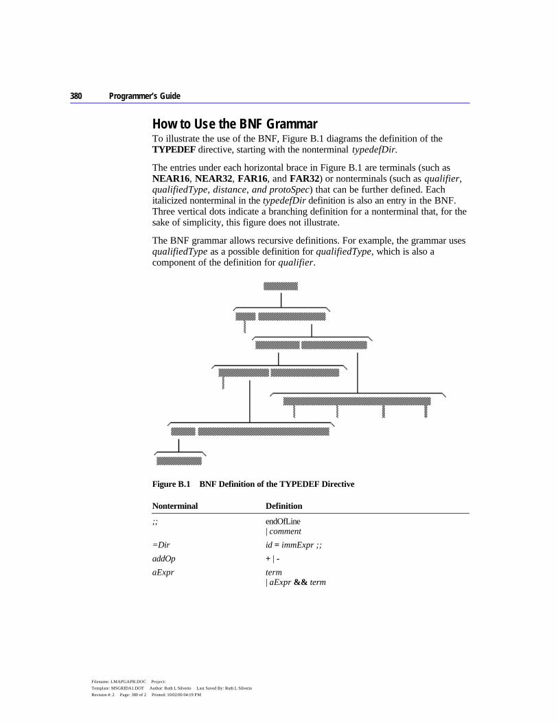
380 Programmer’s Guide
Filename: LMAPGAPB.DOC Project: Template: MSGRIDA1.DOT Author: Ruth L Silverio Last Saved By: Ruth L Silverio Revision #: 2 Page: 380 of 2 Printed: 10/02/00 04:19 PM
How to Use the BNF Grammar To illustrate the use of the BNF, Figure B.1 diagrams the definition of the TYPEDEF directive, starting with the nonterminal typedefDir.
The entries under each horizontal brace in Figure B.1 are terminals (such as NEAR16, NEAR32, FAR16, and FAR32) or nonterminals (such as qualifier, qualifiedType, distance, and protoSpec) that can be further defined. Each italicized nonterminal in the typedefDir definition is also an entry in the BNF. Three vertical dots indicate a branching definition for a nonterminal that, for the sake of simplicity, this figure does not illustrate.
The BNF grammar allows recursive definitions. For example, the grammar uses qualifiedType as a possible definition for qualifiedType, which is also a component of the definition for qualifier.
Figure B.1 BNF Definition of the TYPEDEF Directive
Nonterminal Definition
;; endOfLine | comment
=Dir id = immExpr ;; addOp + | - aExpr term
| aExpr && term
Appendix B BNF Grammar 381
Filename: LMAPGAPB.DOC Project: Template: MSGRIDA1.DOT Author: Ruth L Silverio Last Saved By: Ruth L Silverio Revision #: 2 Page: 381 of 3 Printed: 10/02/00 04:19 PM
Nonterminal Definition
altId id arbitraryText charList asmInstruction mnemonic [[ exprList ]] assumeDir ASSUME assumeList ;;
| ASSUME NOTHING ;; assumeList assumeRegister
| assumeList , assumeRegister assumeReg register : assumeVal assumeRegister assumeSegReg
| assumeReg assumeSegReg segmentRegister : assumeSegVal assumeSegVal frameExpr
| NOTHING | ERROR assumeVal qualifiedType
| NOTHING | ERROR bcdConst [[ sign ]] decNumber binaryOp == | != | >= | <= | > | < | & bitDef bitFieldId : bitFieldSize [[ = constExpr ]] bitDefList bitDef
| bitDefList , [[ ;; ]] bitDef bitFieldId id bitFieldSize constExpr blockStatements directiveList
| .CONTINUE [[ .IF cExpr ]] | .BREAK [[ .IF cExpr ]]
bool TRUE | FALSE byteRegister AL | AH | BL | BH | CL | CH | DL | DH cExpr aExpr
| cExpr || aExpr character Any character with ordinal in the range 0–255
except linefeed (10) charList character
| charList character className string commDecl [[ nearfar ]] [[ langType ]] id : commType
[[ : constExpr ]] commDir COMM commList ;; comment ; text ;;
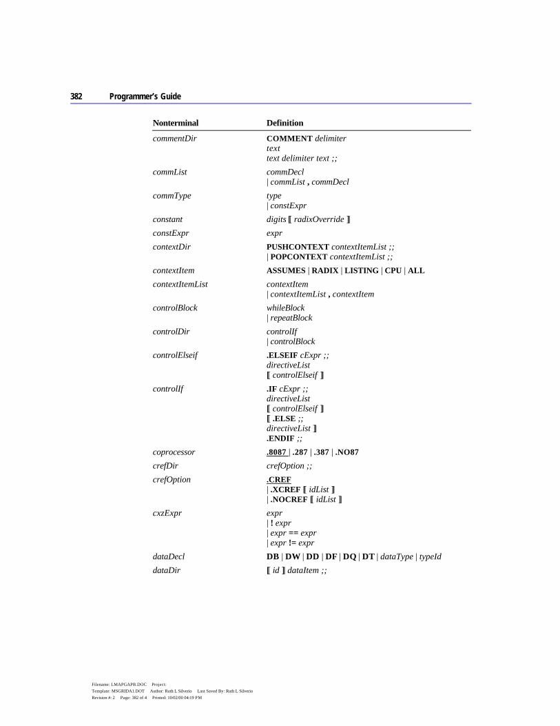
382 Programmer’s Guide
Filename: LMAPGAPB.DOC Project: Template: MSGRIDA1.DOT Author: Ruth L Silverio Last Saved By: Ruth L Silverio Revision #: 2 Page: 382 of 4 Printed: 10/02/00 04:19 PM
Nonterminal Definition
commentDir COMMENT delimiter text text delimiter text ;;
commList commDecl | commList , commDecl
commType type | constExpr
constant digits [[ radixOverride ]] constExpr expr contextDir PUSHCONTEXT contextItemList ;;
| POPCONTEXT contextItemList ;; contextItem ASSUMES | RADIX | LISTING | CPU | ALL contextItemList contextItem
| contextItemList , contextItem controlBlock whileBlock
| repeatBlock controlDir controlIf
| controlBlock controlElseif .ELSEIF cExpr ;;
directiveList [[ controlElseif ]]
controlIf .IF cExpr ;; directiveList [[ controlElseif ]] [[ .ELSE ;; directiveList ]] .ENDIF ;;
coprocessor .8087 | .287 | .387 | .NO87 crefDir crefOption ;; crefOption .CREF
| .XCREF [[ idList ]] | .NOCREF [[ idList ]]
cxzExpr expr | ! expr | expr == expr | expr != expr
dataDecl DB | DW | DD | DF | DQ | DT | dataType | typeId dataDir [[ id ]] dataItem ;;
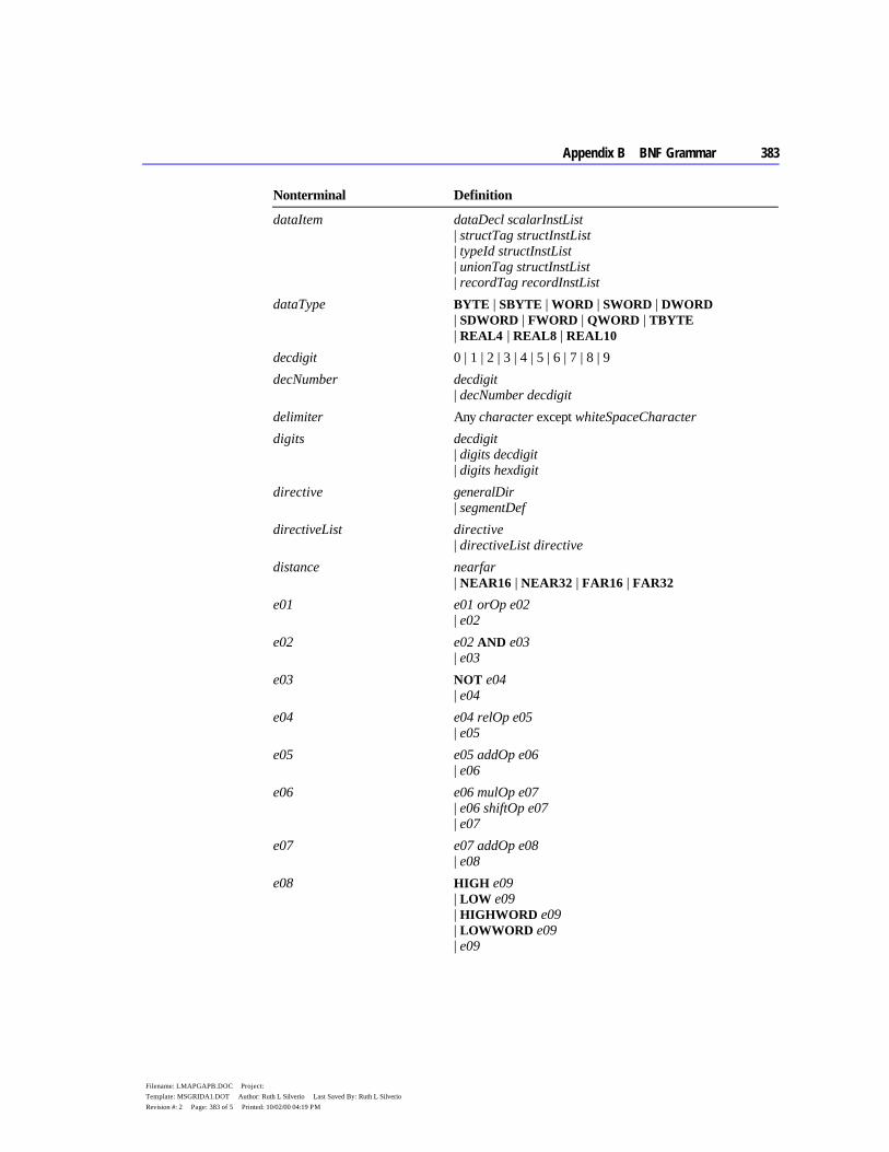
Appendix B BNF Grammar 383
Filename: LMAPGAPB.DOC Project: Template: MSGRIDA1.DOT Author: Ruth L Silverio Last Saved By: Ruth L Silverio Revision #: 2 Page: 383 of 5 Printed: 10/02/00 04:19 PM
Nonterminal Definition
dataItem dataDecl scalarInstList | structTag structInstList | typeId structInstList | unionTag structInstList | recordTag recordInstList
dataType BYTE | SBYTE | WORD | SWORD | DWORD | SDWORD | FWORD | QWORD | TBYTE | REAL4 | REAL8 | REAL10
decdigit 0 | 1 | 2 | 3 | 4 | 5 | 6 | 7 | 8 | 9 decNumber decdigit
| decNumber decdigit delimiter Any character except whiteSpaceCharacter digits decdigit
| digits decdigit | digits hexdigit
directive generalDir | segmentDef
directiveList directive | directiveList directive
distance nearfar | NEAR16 | NEAR32 | FAR16 | FAR32
e01 e01 orOp e02 | e02
e02 e02 AND e03 | e03
e03 NOT e04 | e04
e04 e04 relOp e05 | e05
e05 e05 addOp e06 | e06
e06 e06 mulOp e07 | e06 shiftOp e07 | e07
e07 e07 addOp e08 | e08
e08 HIGH e09 | LOW e09 | HIGHWORD e09 | LOWWORD e09 | e09
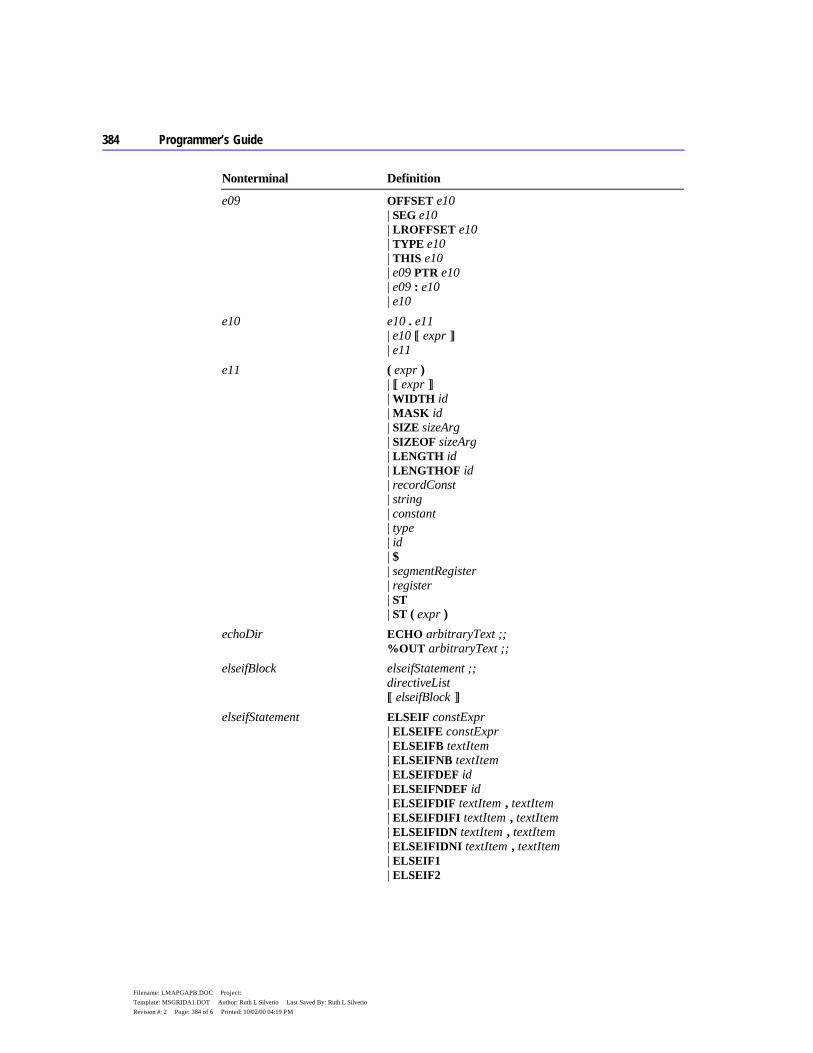
384 Programmer’s Guide
Filename: LMAPGAPB.DOC Project: Template: MSGRIDA1.DOT Author: Ruth L Silverio Last Saved By: Ruth L Silverio Revision #: 2 Page: 384 of 6 Printed: 10/02/00 04:19 PM
Nonterminal Definition
e09 OFFSET e10 | SEG e10 | LROFFSET e10 | TYPE e10 | THIS e10 | e09 PTR e10 | e09 : e10 | e10
e10 e10 . e11 | e10 [[ expr ]] | e11
e11 ( expr ) | [[ expr ]] | WIDTH id | MASK id | SIZE sizeArg | SIZEOF sizeArg | LENGTH id | LENGTHOF id | recordConst | string | constant | type | id | $ | segmentRegister | register | ST | ST ( expr )
echoDir ECHO arbitraryText ;; %OUT arbitraryText ;;
elseifBlock elseifStatement ;; directiveList [[ elseifBlock ]]
elseifStatement ELSEIF constExpr | ELSEIFE constExpr | ELSEIFB textItem | ELSEIFNB textItem | ELSEIFDEF id | ELSEIFNDEF id | ELSEIFDIF textItem , textItem | ELSEIFDIFI textItem , textItem | ELSEIFIDN textItem , textItem | ELSEIFIDNI textItem , textItem | ELSEIF1 | ELSEIF2

Appendix B BNF Grammar 385
Filename: LMAPGAPB.DOC Project: Template: MSGRIDA1.DOT Author: Ruth L Silverio Last Saved By: Ruth L Silverio Revision #: 2 Page: 385 of 7 Printed: 10/02/00 04:19 PM
Nonterminal Definition
endDir END [[ immExpr ]] ;; endpDir procId ENDP ;; endsDir id ENDS ;; equDir textMacroId EQU equType ;; equType immExpr
| textLiteral errorDir errorOpt ;; errorOpt .ERR [[ textItem ]]
| .ERRE constExpr [[ optText ]] | .ERRNZ constExpr [[ optText ]] | .ERRB textItem [[ optText ]] | .ERRNB textItem [[ optText ]] | .ERRDEF id [[ optText ]] | .ERRNDEF id [[ optText ]] | .ERRDIF textItem , textItem [[ optText ]] | .ERRDIFI textItem , textItem [[ optText ]] | .ERRIDN textItem , textItem [[ optText ]] | .ERRIDNI textItem , textItem [[ optText ]] | .ERR1 [[ textItem ]] | .ERR2 [[ textItem ]]
exitDir .EXIT [[ expr ]] ;; exitmDir: EXITM
| EXITM textItem exponent E [[ sign ]] decNumber expr SHORT e05
| .TYPE e01 | OPATTR e01 | e01
exprList expr | exprList , expr
externDef [[ langType ]] id [[ ( altId ) ]] : externType externDir externKey externList ;; externKey EXTRN | EXTERN | EXTERNDEF externList externDef
| externList , [[ ;; ]] externDef externType ABS
| qualifiedType fieldAlign constExpr fieldInit [[ initValue ]]
| structInstance
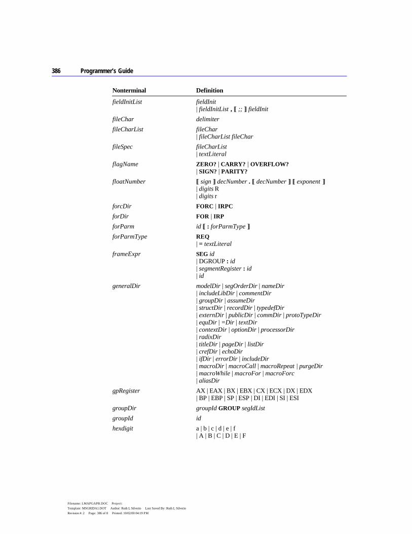
386 Programmer’s Guide
Filename: LMAPGAPB.DOC Project: Template: MSGRIDA1.DOT Author: Ruth L Silverio Last Saved By: Ruth L Silverio Revision #: 2 Page: 386 of 8 Printed: 10/02/00 04:19 PM
Nonterminal Definition
fieldInitList fieldInit | fieldInitList , [[ ;; ]] fieldInit
fileChar delimiter fileCharList fileChar
| fileCharList fileChar fileSpec fileCharList
| textLiteral flagName ZERO? | CARRY? | OVERFLOW?
| SIGN? | PARITY? floatNumber [[ sign ]] decNumber . [[ decNumber ]] [[ exponent ]]
| digits R | digits r
forcDir FORC | IRPC forDir FOR | IRP forParm id [[ : forParmType ]] forParmType REQ
| = textLiteral frameExpr SEG id
| DGROUP : id | segmentRegister : id | id
generalDir modelDir | segOrderDir | nameDir | includeLibDir | commentDir | groupDir | assumeDir | structDir | recordDir | typedefDir | externDir | publicDir | commDir | protoTypeDir | equDir | =Dir | textDir | contextDir | optionDir | processorDir | radixDir | titleDir | pageDir | listDir | crefDir | echoDir | ifDir | errorDir | includeDir | macroDir | macroCall | macroRepeat | purgeDir | macroWhile | macroFor | macroForc | aliasDir
gpRegister AX | EAX | BX | EBX | CX | ECX | DX | EDX | BP | EBP | SP | ESP | DI | EDI | SI | ESI
groupDir groupId GROUP segIdList groupId id hexdigit a | b | c | d | e | f
| A | B | C | D | E | F
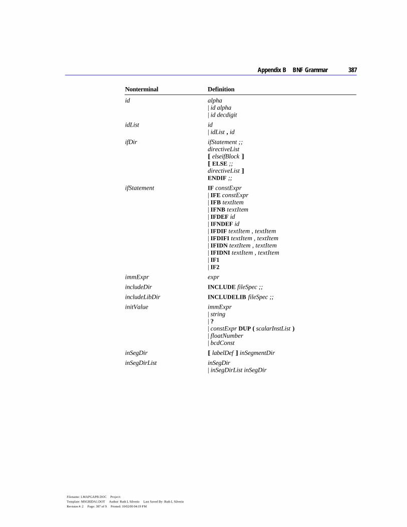
Appendix B BNF Grammar 387
Filename: LMAPGAPB.DOC Project: Template: MSGRIDA1.DOT Author: Ruth L Silverio Last Saved By: Ruth L Silverio Revision #: 2 Page: 387 of 9 Printed: 10/02/00 04:19 PM
Nonterminal Definition
id alpha | id alpha | id decdigit
idList id | idList , id
ifDir ifStatement ;; directiveList [[ elseifBlock ]] [[ ELSE ;; directiveList ]] ENDIF ;;
ifStatement IF constExpr | IFE constExpr | IFB textItem | IFNB textItem | IFDEF id | IFNDEF id | IFDIF textItem , textItem | IFDIFI textItem , textItem | IFIDN textItem , textItem | IFIDNI textItem , textItem | IF1 | IF2
immExpr expr includeDir INCLUDE fileSpec ;; includeLibDir INCLUDELIB fileSpec ;; initValue immExpr
| string | ? | constExpr DUP ( scalarInstList ) | floatNumber | bcdConst
inSegDir [[ labelDef ]] inSegmentDir inSegDirList inSegDir
| inSegDirList inSegDir
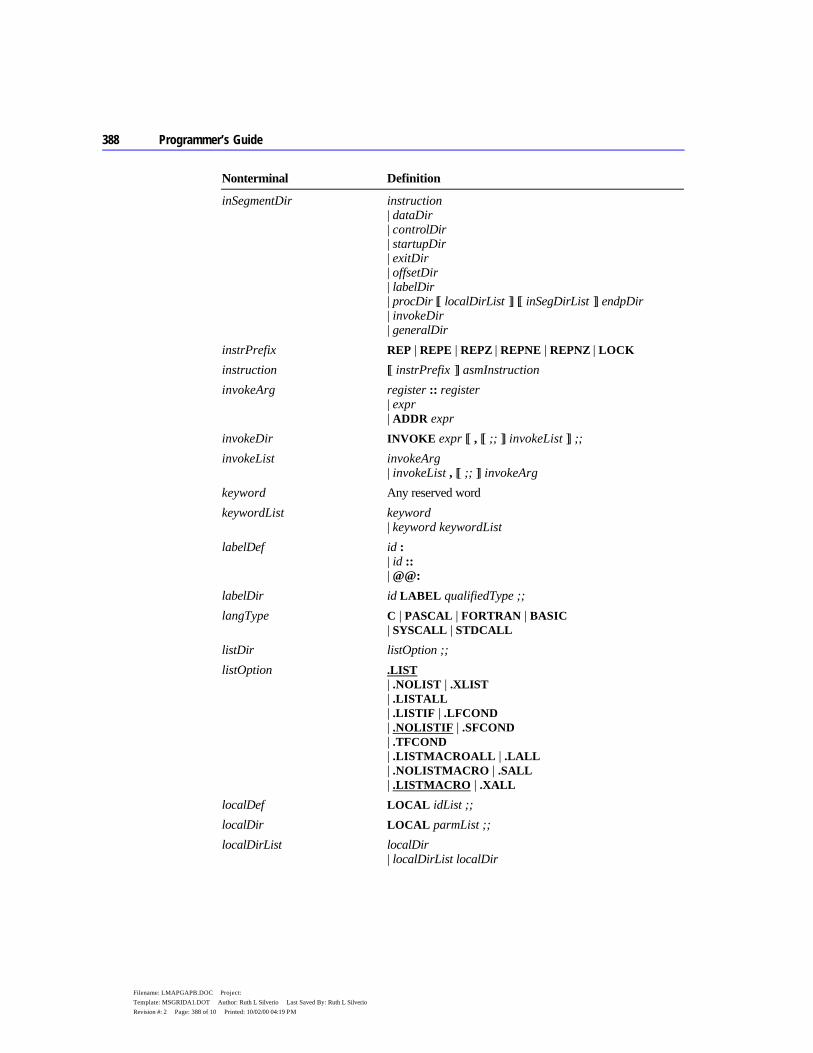
388 Programmer’s Guide
Filename: LMAPGAPB.DOC Project: Template: MSGRIDA1.DOT Author: Ruth L Silverio Last Saved By: Ruth L Silverio Revision #: 2 Page: 388 of 10 Printed: 10/02/00 04:19 PM
Nonterminal Definition
inSegmentDir instruction | dataDir | controlDir | startupDir | exitDir | offsetDir | labelDir | procDir [[ localDirList ]] [[ inSegDirList ]] endpDir | invokeDir | generalDir
instrPrefix REP | REPE | REPZ | REPNE | REPNZ | LOCK instruction [[ instrPrefix ]] asmInstruction invokeArg register :: register
| expr | ADDR expr
invokeDir INVOKE expr [[ , [[ ;; ]] invokeList ]] ;; invokeList invokeArg
| invokeList , [[ ;; ]] invokeArg keyword Any reserved word keywordList keyword
| keyword keywordList labelDef id :
| id :: | @@:
labelDir id LABEL qualifiedType ;; langType C | PASCAL | FORTRAN | BASIC
| SYSCALL | STDCALL listDir listOption ;; listOption .LIST
| .NOLIST | .XLIST | .LISTALL | .LISTIF | .LFCOND | .NOLISTIF | .SFCOND | .TFCOND | .LISTMACROALL | .LALL | .NOLISTMACRO | .SALL | .LISTMACRO | .XALL
localDef LOCAL idList ;; localDir LOCAL parmList ;; localDirList localDir
| localDirList localDir
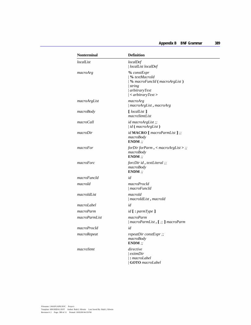
Appendix B BNF Grammar 389
Filename: LMAPGAPB.DOC Project: Template: MSGRIDA1.DOT Author: Ruth L Silverio Last Saved By: Ruth L Silverio Revision #: 2 Page: 389 of 11 Printed: 10/02/00 04:19 PM
Nonterminal Definition
localList localDef | localList localDef
macroArg % constExpr | % textMacroId | % macroFuncId ( macroArgList ) | string | arbitraryText | < arbitraryText >
macroArgList macroArg | macroArgList , macroArg
macroBody [[ localList ]] macroStmtList
macroCall id macroArgList ;; | id ( macroArgList )
macroDir id MACRO [[ macroParmList ]] ;; macroBody ENDM ;;
macroFor forDir forParm , < macroArgList > ;; macroBody ENDM ;;
macroForc forcDir id , textLiteral ;; macroBody ENDM ;;
macroFuncId id macroId macroProcId
| macroFuncId macroIdList macroId
| macroIdList , macroId macroLabel id macroParm id [[ : parmType ]] macroParmList macroParm
| macroParmList , [[ ;; ]] macroParm macroProcId id macroRepeat repeatDir constExpr ;;
macroBody ENDM ;;
macroStmt directive | exitmDir | : macroLabel | GOTO macroLabel
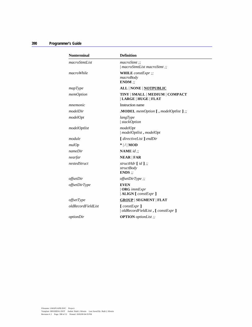
390 Programmer’s Guide
Filename: LMAPGAPB.DOC Project: Template: MSGRIDA1.DOT Author: Ruth L Silverio Last Saved By: Ruth L Silverio Revision #: 2 Page: 390 of 12 Printed: 10/02/00 04:19 PM
Nonterminal Definition
macroStmtList macroStmt ;; | macroStmtList macroStmt ;;
macroWhile WHILE constExpr ;; macroBody ENDM ;;
mapType ALL | NONE | NOTPUBLIC memOption TINY | SMALL | MEDIUM | COMPACT
| LARGE | HUGE | FLAT mnemonic Instruction name modelDir .MODEL memOption [[ , modelOptlist ]] ;; modelOpt langType
| stackOption modelOptlist modelOpt
| modelOptlist , modelOpt module [[ directiveList ]] endDir mulOp * | / | MOD nameDir NAME id ;; nearfar NEAR | FAR nestedStruct structHdr [[ id ]] ;;
structBody ENDS ;;
offsetDir offsetDirType ;; offsetDirType EVEN
| ORG immExpr | ALIGN [[ constExpr ]]
offsetType GROUP | SEGMENT | FLAT oldRecordFieldList [[ constExpr ]]
| oldRecordFieldList , [[ constExpr ]] optionDir OPTION optionList ;;
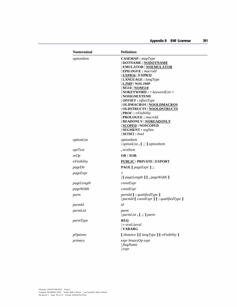
Appendix B BNF Grammar 391
Filename: LMAPGAPB.DOC Project: Template: MSGRIDA1.DOT Author: Ruth L Silverio Last Saved By: Ruth L Silverio Revision #: 2 Page: 391 of 13 Printed: 10/02/00 04:19 PM
Nonterminal Definition
optionItem CASEMAP : mapType | DOTNAME | NODOTNAME | EMULATOR | NOEMULATOR | EPILOGUE : macroId | EXPR16 | EXPR32 | LANGUAGE : langType | LJMP | NOLJMP | M510 | NOM510 | NOKEYWORD : < keywordList > | NOSIGNEXTEND | OFFSET : offsetType | OLDMACROS | NOOLDMACROS | OLDSTRUCTS | NOOLDSTRUCTS | PROC : oVisibility | PROLOGUE : macroId | READONLY | NOREADONLY | SCOPED | NOSCOPED | SEGMENT : segSize | SETIF2 : bool
optionList optionItem | optionList , [[ ;; ]] optionItem
optText , textItem orOp OR | XOR oVisibility PUBLIC | PRIVATE | EXPORT pageDir PAGE [[ pageExpr ]] ;; pageExpr +
| [[ pageLength ]] [[ , pageWidth ]] pageLength constExpr pageWidth constExpr parm parmId [[ : qualifiedType ]]
| parmId [[ constExpr ]] [[ : qualifiedType ]] parmId id parmList parm
| parmList , [[ ;; ]] parm parmType REQ
| = textLiteral | VARARG
pOptions [[ distance ]] [[ langType ]] [[ oVisibility ]] primary expr binaryOp expr
| flagName | expr
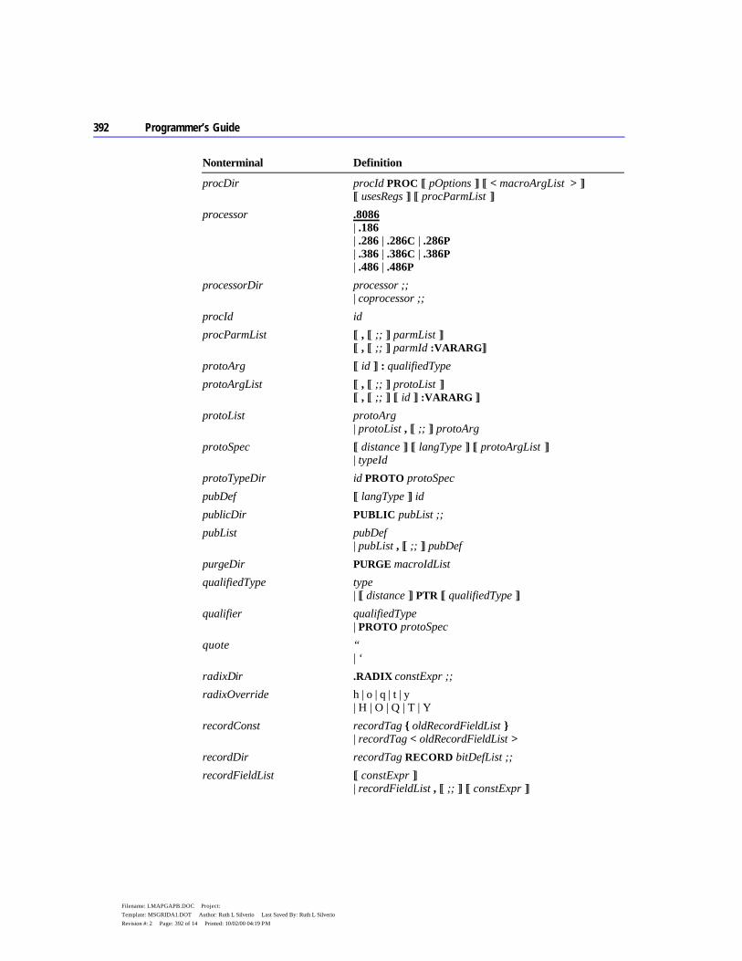
392 Programmer’s Guide
Filename: LMAPGAPB.DOC Project: Template: MSGRIDA1.DOT Author: Ruth L Silverio Last Saved By: Ruth L Silverio Revision #: 2 Page: 392 of 14 Printed: 10/02/00 04:19 PM
Nonterminal Definition
procDir procId PROC [[ pOptions ]] [[ < macroArgList > ]] [[ usesRegs ]] [[ procParmList ]]
processor .8086 | .186 | .286 | .286C | .286P | .386 | .386C | .386P | .486 | .486P
processorDir processor ;; | coprocessor ;;
procId id procParmList [[ , [[ ;; ]] parmList ]]
[[ , [[ ;; ]] parmId :VARARG]] protoArg [[ id ]] : qualifiedType protoArgList [[ , [[ ;; ]] protoList ]]
[[ , [[ ;; ]] [[ id ]] :VARARG ]] protoList protoArg
| protoList , [[ ;; ]] protoArg protoSpec [[ distance ]] [[ langType ]] [[ protoArgList ]]
| typeId protoTypeDir id PROTO protoSpec pubDef [[ langType ]] id publicDir PUBLIC pubList ;; pubList pubDef
| pubList , [[ ;; ]] pubDef purgeDir PURGE macroIdList qualifiedType type
| [[ distance ]] PTR [[ qualifiedType ]] qualifier qualifiedType
| PROTO protoSpec quote “
| ‘ radixDir .RADIX constExpr ;; radixOverride h | o | q | t | y
| H | O | Q | T | Y recordConst recordTag { oldRecordFieldList }
| recordTag < oldRecordFieldList > recordDir recordTag RECORD bitDefList ;; recordFieldList [[ constExpr ]]
| recordFieldList , [[ ;; ]] [[ constExpr ]]

Appendix B BNF Grammar 393
Filename: LMAPGAPB.DOC Project: Template: MSGRIDA1.DOT Author: Ruth L Silverio Last Saved By: Ruth L Silverio Revision #: 2 Page: 393 of 15 Printed: 10/02/00 04:19 PM
Nonterminal Definition
recordInstance { [[ ;; ]] recordFieldList [[ ;; ]] } | < oldRecordFieldList > | constExpr DUP ( recordInstance )
recordInstList recordInstance | recordInstList , [[ ;; ]] recordInstance
recordTag id register specialRegister
| gpRegister | byteRegister
regList register | regList register
relOp EQ | NE | LT | LE | GT | GE repeatBlock .REPEAT ;;
blockStatements ;; untilDir ;;
repeatDir REPEAT | REPT scalarInstList initValue
| scalarInstList , [[ ;; ]] initValue segAlign BYTE | WORD | DWORD | PARA | PAGE segAttrib PUBLIC
| STACK | COMMON | MEMORY | AT constExpr | PRIVATE
segDir .CODE [[ segId ]] | .DATA | .DATA? | .CONST | .FARDATA [[ segId ]] | .FARDATA? [[ segId ]] | .STACK [[ constExpr ]]
segId id segIdList segId
| segIdList , segId segmentDef segmentDir [[ inSegDirList ]] endsDir
| simpleSegDir [[ inSegDirList ]] [[ endsDir ]] segmentDir segId SEGMENT [[ segOptionList ]] ;; segmentRegister CS | DS | ES | FS | GS | SS
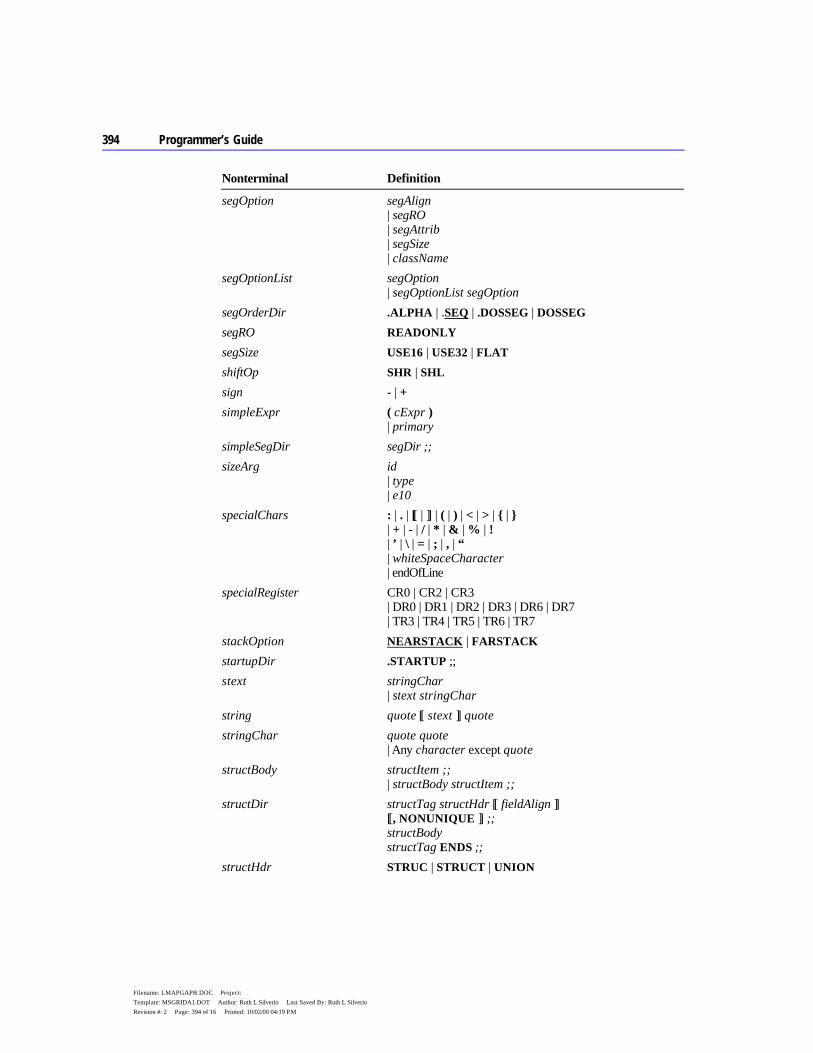
394 Programmer’s Guide
Filename: LMAPGAPB.DOC Project: Template: MSGRIDA1.DOT Author: Ruth L Silverio Last Saved By: Ruth L Silverio Revision #: 2 Page: 394 of 16 Printed: 10/02/00 04:19 PM
Nonterminal Definition
segOption segAlign | segRO | segAttrib | segSize | className
segOptionList segOption | segOptionList segOption
segOrderDir .ALPHA | .SEQ | .DOSSEG | DOSSEG segRO READONLY segSize USE16 | USE32 | FLAT shiftOp SHR | SHL sign - | + simpleExpr ( cExpr )
| primary simpleSegDir segDir ;; sizeArg id
| type | e10
specialChars : | . | [[ | ]] | ( | ) | < | > | { | } | + | - | / | * | & | % | ! | ’ | \ | = | ; | , | “ | whiteSpaceCharacter | endOfLine
specialRegister CR0 | CR2 | CR3 | DR0 | DR1 | DR2 | DR3 | DR6 | DR7 | TR3 | TR4 | TR5 | TR6 | TR7
stackOption NEARSTACK | FARSTACK startupDir .STARTUP ;;
stext stringChar | stext stringChar
string quote [[ stext ]] quote stringChar quote quote
| Any character except quote structBody structItem ;;
| structBody structItem ;; structDir structTag structHdr [[ fieldAlign ]]
[[, NONUNIQUE ]] ;; structBody structTag ENDS ;;
structHdr STRUC | STRUCT | UNION
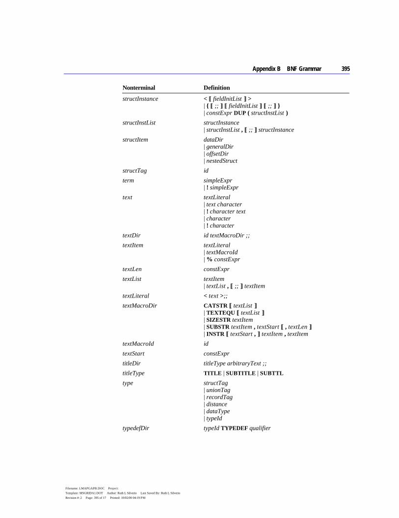
Appendix B BNF Grammar 395
Filename: LMAPGAPB.DOC Project: Template: MSGRIDA1.DOT Author: Ruth L Silverio Last Saved By: Ruth L Silverio Revision #: 2 Page: 395 of 17 Printed: 10/02/00 04:19 PM
Nonterminal Definition
structInstance < [[ fieldInitList ]] > | { [[ ;; ]] [[ fieldInitList ]] [[ ;; ]] } | constExpr DUP ( structInstList )
structInstList structInstance | structInstList , [[ ;; ]] structInstance
structItem dataDir | generalDir | offsetDir | nestedStruct
structTag id term simpleExpr
| ! simpleExpr text textLiteral
| text character | ! character text | character | ! character
textDir id textMacroDir ;; textItem textLiteral
| textMacroId | % constExpr
textLen constExpr textList textItem
| textList , [[ ;; ]] textItem textLiteral < text >;; textMacroDir CATSTR [[ textList ]]
| TEXTEQU [[ textList ]] | SIZESTR textItem | SUBSTR textItem , textStart [[ , textLen ]] | INSTR [[ textStart , ]] textItem , textItem
textMacroId id textStart constExpr titleDir titleType arbitraryText ;; titleType TITLE | SUBTITLE | SUBTTL type structTag
| unionTag | recordTag | distance | dataType | typeId
typedefDir typeId TYPEDEF qualifier

396 Programmer’s Guide
Filename: LMAPGAPB.DOC Project: Template: MSGRIDA1.DOT Author: Ruth L Silverio Last Saved By: Ruth L Silverio Revision #: 2 Page: 396 of 18 Printed: 10/02/00 04:19 PM
Nonterminal Definition
typeId id unionTag id untilDir .UNTIL cExpr ;;
.UNTILCXZ [[ cxzExpr ]] ;; usesRegs USES regList whileBlock .WHILE cExpr ;;
blockStatements ;; .ENDW
whiteSpaceCharacter ASCII 8, 9, 11–13, 26, 32
397
Filename: LMAPGAPC.DOC Project: Template: MSGRIDA1.DOT Author: Ruth L Silverio Last Saved By: Ruth L Silverio Revision #: 2 Page: 397 of 1 Printed: 10/02/00 04:19 PM
A P P E N D I X
A listing file shows precisely how the assembler translates your source file into machine code. The listing documents the assembler’s assumptions, memory allocations, and optimizations.
MASM creates an assembly listing of your source file whenever you do one of the following:
u Select the appropriate option in PWB. u Use one of the related source code directives. u Specify the /Fl option on the MASM command line.
The assembly listing contains both the statements in the source file and the binary code (if any) generated for each statement. The listing also shows the names and values of all labels, variables, and symbols in your file.
The assembler creates tables for macros, structures, unions, records, segments, groups, and other symbols, and places the tables at the end of the assembly listing. Only the types of symbols encountered in the program are included. For example, if your program has no macros, the symbol table does not have a macros section.
Generating Listing Files To generate a listing file from within PWB, follow these steps:
1. From the Options menu, choose MASM Options. 2. In the MASM Options dialog box, choose Set Debug or Release Options.
The dialog box for Set Debug or Release Options lists the choices summarized in Table C.1. This table also shows the equivalent source code directives and command-line options.
Generating and Reading Assembly Listings
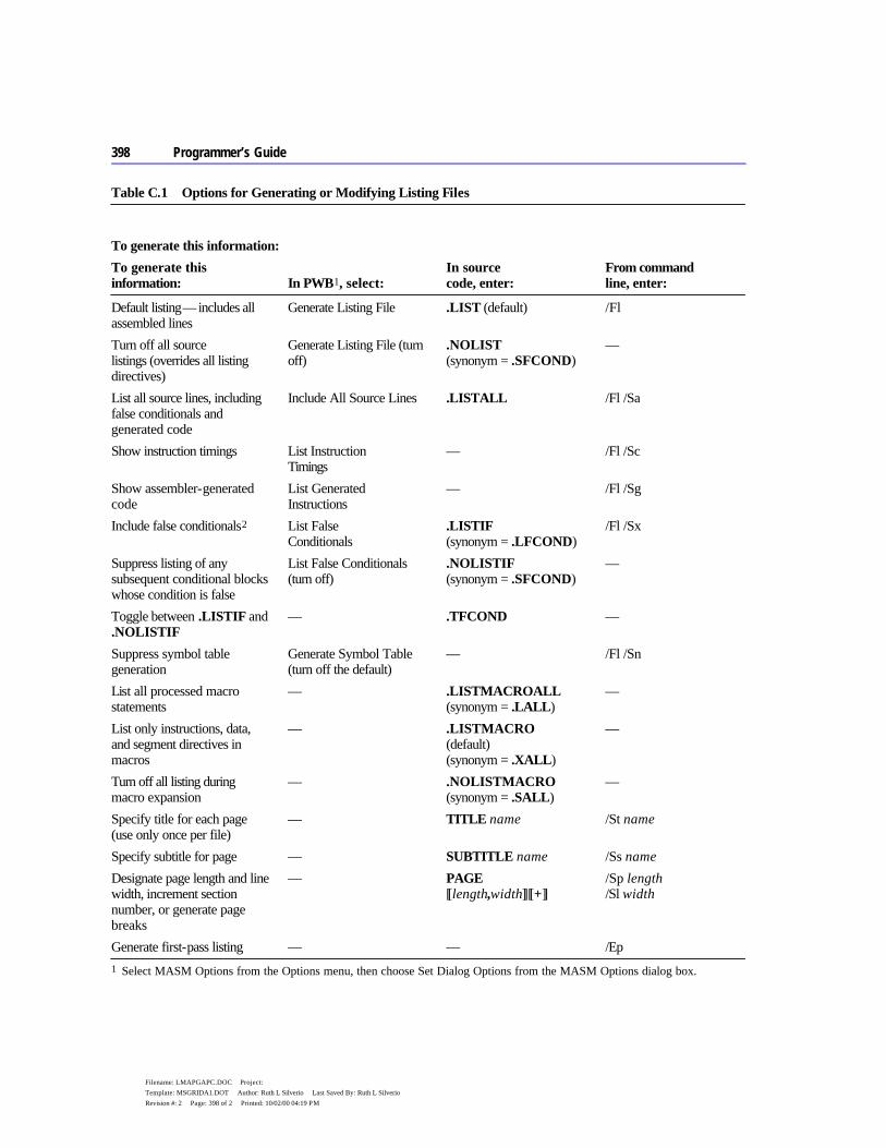
398 Programmer’s Guide
Filename: LMAPGAPC.DOC Project: Template: MSGRIDA1.DOT Author: Ruth L Silverio Last Saved By: Ruth L Silverio Revision #: 2 Page: 398 of 2 Printed: 10/02/00 04:19 PM
Table C.1 Options for Generating or Modifying Listing Files
To generate this information:
To generate this information:
In PWB1, select:
In source code, enter:
From command line, enter:
Default listing — includes all assembled lines
Generate Listing File .LIST (default) /Fl
Turn off all source listings (overrides all listing directives)
Generate Listing File (turn off)
.NOLIST (synonym = .SFCOND)
—
List all source lines, including false conditionals and generated code
Include All Source Lines .LISTALL /Fl /Sa
Show instruction timings List Instruction Timings
— /Fl /Sc
Show assembler-generated code
List Generated Instructions
— /Fl /Sg
Include false conditionals2 List False Conditionals
.LISTIF (synonym = .LFCOND)
/Fl /Sx
Suppress listing of any subsequent conditional blocks whose condition is false
List False Conditionals (turn off)
.NOLISTIF (synonym = .SFCOND)
—
Toggle between .LISTIF and .NOLISTIF
— .TFCOND —
Suppress symbol table generation
Generate Symbol Table (turn off the default)
— /Fl /Sn
List all processed macro statements
— .LISTMACROALL (synonym = .LALL)
—
List only instructions, data, and segment directives in macros
— .LISTMACRO (default) (synonym = .XALL)
—
Turn off all listing during macro expansion
— .NOLISTMACRO (synonym = .SALL)
—
Specify title for each page (use only once per file)
— TITLE name /St name
Specify subtitle for page — SUBTITLE name /Ss name
Designate page length and line width, increment section number, or generate page breaks
— PAGE [[length,width]][[+]]
/Sp length /Sl width
Generate first-pass listing — — /Ep 1 Select MASM Options from the Options menu, then choose Set Dialog Options from the MASM Options dialog box.
Appendix C Generating and Reading Assembly Listings 399
Filename: LMAPGAPC.DOC Project: Template: MSGRIDA1.DOT Author: Ruth L Silverio Last Saved By: Ruth L Silverio Revision #: 2 Page: 399 of 3 Printed: 10/02/00 04:19 PM
2 See “Conditional Directives” in Chapter 1
Precedence of Command-Line Options and Listing Directives Since command-line options and source code directives can specify opposite behavior for the same listing file option, the assembler interprets the commands according to the following precedence levels. Selecting PWB options is equivalent to specifying /Fl /Sx on the command line:
u /Sa overrides any source code directives that suppress listing. u Source code directives override all command-line options except /Sa. u .NOLIST overrides other listing directives such as .NOLISTIF and
.LISTMACROALL. u The /Sx, /Ss, /Sp, and /Sl options set initial values for their respective
features. Directives in the source file can override these command-line options.
Reading the Listing File The first half of the listing shows macros from the include file DOS.MAC, structure declarations, and data. After the .DATA directive, the columns on the left show offsets and initialized byte values within the data segment.
Instructions begin after the .CODE directive. The three columns on the left show offsets, instruction timings, and binary code generated by the assembler. The columns on the right list the source statements exactly as they appear in the source file or as expanded by a macro. Various symbols and abbreviations in the middle column provide information about the code, as explained in the following section. The subsequent section, “Symbols and Abbreviations,” explains the meanings of listing symbols.
Generated Code The assembler lists the code generated from the statements of a source file. With the /Sc command-line switch, which generates instruction timings, each line has this syntax:
offset [[timing]] [[code]]
The offset is the offset from the beginning of the current code segment. The timing shows the number of cycles the processor needs to execute the instruction. The value of timing reflects the CPU type; for example, specifying the .386 directive produces instruction timings for the 80386 processor. If the statement generates code or data, code shows the numeric value in hexadecimal
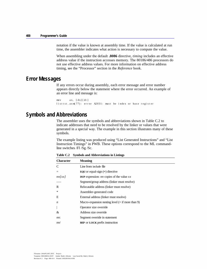
400 Programmer’s Guide
Filename: LMAPGAPC.DOC Project: Template: MSGRIDA1.DOT Author: Ruth L Silverio Last Saved By: Ruth L Silverio Revision #: 2 Page: 400 of 4 Printed: 10/02/00 04:19 PM
notation if the value is known at assembly time. If the value is calculated at run time, the assembler indicates what action is necessary to compute the value.
When assembling under the default .8086 directive, timing includes an effective address value if the instruction accesses memory. The 80186/486 processors do not use effective address values. For more information on effective address timing, see the “Processor” section in the Reference book.
Error Messages If any errors occur during assembly, each error message and error number appears directly below the statement where the error occurred. An example of an error line and message is:
mov ax, [dx][di] listtst.asm(77): error A2031: must be index or base register
Symbols and Abbreviations The assembler uses the symbols and abbreviations shown in Table C.2 to indicate addresses that need to be resolved by the linker or values that were generated in a special way. The example in this section illustrates many of these symbols.
The example listing was produced using “List Generated Instructions” and “List Instruction Timings” in PWB. These options correspond to the ML command-line switches /Fl /Sg /Sc.
Table C.2 Symbols and Abbreviations in Listings
Character Meaning
C Line from include file = EQU or equal-sign (=) directive nn[xx] DUP expression: nn copies of the value xx ---- Segment/group address (linker must resolve) R Relocatable address (linker must resolve) * Assembler-generated code E External address (linker must resolve) n Macro-expansion nesting level (+ if more than 9) | Operator size override & Address size override nn: Segment override in statement nn/ REP or LOCK prefix instruction

Appendix C Generating and Reading Assembly Listings 401
Filename: LMAPGAPC.DOC Project: Template: MSGRIDA1.DOT Author: Ruth L Silverio Last Saved By: Ruth L Silverio Revision #: 2 Page: 401 of 5 Printed: 10/02/00 04:19 PM
Table C.3 explains the five symbols that may follow timing values in your listing. The Reference book will help you determine correct timings for those values marked with a symbol.
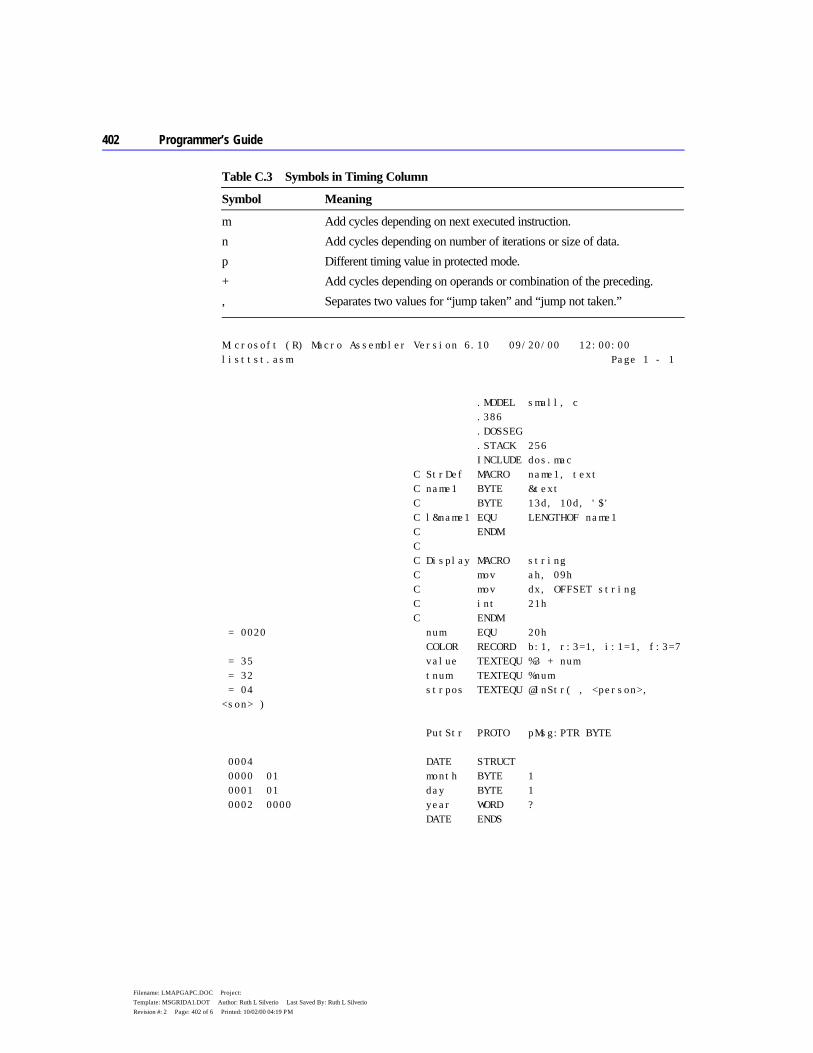
402 Programmer’s Guide
Filename: LMAPGAPC.DOC Project: Template: MSGRIDA1.DOT Author: Ruth L Silverio Last Saved By: Ruth L Silverio Revision #: 2 Page: 402 of 6 Printed: 10/02/00 04:19 PM
Table C.3 Symbols in Timing Column
Symbol Meaning
m Add cycles depending on next executed instruction. n Add cycles depending on number of iterations or size of data. p Different timing value in protected mode. + Add cycles depending on operands or combination of the preceding. , Separates two values for “jump taken” and “jump not taken.”
Microsoft (R) Macro Assembler Version 6.10 09/20/00 12:00:00 listtst.asm Page 1 - 1 .MODEL small, c .386 .DOSSEG .STACK 256 INCLUDE dos.mac C StrDef MACRO name1, text C name1 BYTE &text C BYTE 13d, 10d, '$' C l&name1 EQU LENGTHOF name1 C ENDM C C Display MACRO string C mov ah, 09h C mov dx, OFFSET string C int 21h C ENDM = 0020 num EQU 20h COLOR RECORD b:1, r:3=1, i:1=1, f:3=7 = 35 value TEXTEQU %3 + num = 32 tnum TEXTEQU %num = 04 strpos TEXTEQU @InStr( , <person>, <son> ) PutStr PROTO pMsg:PTR BYTE 0004 DATE STRUCT 0000 01 month BYTE 1 0001 01 day BYTE 1 0002 0000 year WORD ? DATE ENDS

Appendix C Generating and Reading Assembly Listings 403
Filename: LMAPGAPC.DOC Project: Template: MSGRIDA1.DOT Author: Ruth L Silverio Last Saved By: Ruth L Silverio Revision #: 2 Page: 403 of 7 Printed: 10/02/00 04:19 PM
0002 U1 UNION 0000 0028 fsize WORD 40 bsize BYTE 60 U1 ENDS 0000 .DATA 0000 00000000 ddData DWORD ? 0004 1F text COLOR <> 0005 01 14 07C9 today DATE <01, 20, 1993> 0009 00 flag BYTE 0 000A 001E [ buffer WORD 30 DUP (0) 0000 ] StrDef ending, "Finished." 0046 46 69 6E 69 73 68 1 ending BYTE "Finished." 65 64 2E 004F 0D 0A 24 1 BYTE 13d, 10d, '$' = 0009 1 lending EQU LENGTHOF ending 0052 54 68 69 73 20 69 Msg BYTE "This is a string","0" 73 20 61 20 73 74 72 69 6E 67 30 float TYPEDEF REAL4 FPBYTE TYPEDEF FAR PTR BYTE 0063 ---- 0052 R FPMSG FPBYTE Msg PBYTE TYPEDEF PTR BYTE NPWORD TYPEDEF NEAR PTR WORD PVOID TYPEDEF PTR PPBYTE TYPEDEF PTR PBYTE 0000 .CODE .STARTUP 0000 *@Startup: 0000 2 B8 ---- R * mov ax, DGROUP 0003 2p 8E D8 * mov ds, ax 0005 2 8C D3 * mov bx, ss 0007 2 2B D8 * sub bx, ax 0009 3 C1 E3 04 * shl bx, 004h 000C 2p 8E D0 * mov ss, ax 000E 2 03 E3 * add sp, bx EXTERNDEF work:NEAR 0010 7m E8 0000 E call work
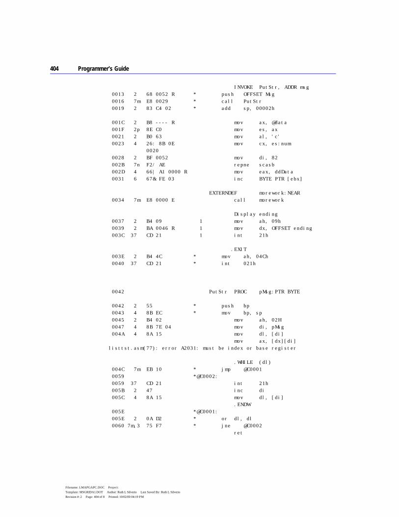
404 Programmer’s Guide
Filename: LMAPGAPC.DOC Project: Template: MSGRIDA1.DOT Author: Ruth L Silverio Last Saved By: Ruth L Silverio Revision #: 2 Page: 404 of 8 Printed: 10/02/00 04:19 PM
INVOKE PutStr, ADDR msg 0013 2 68 0052 R * push OFFSET Msg 0016 7m E8 0029 * call PutStr 0019 2 83 C4 02 * add sp, 00002h 001C 2 B8 ---- R mov ax, @data 001F 2p 8E C0 mov es, ax 0021 2 B0 63 mov al, 'c' 0023 4 26: 8B 0E mov cx, es:num 0020 0028 2 BF 0052 mov di, 82 002B 7n F2/ AE repne scasb 002D 4 66| A1 0000 R mov eax, ddData 0031 6 67& FE 03 inc BYTE PTR [ebx] EXTERNDEF morework:NEAR 0034 7m E8 0000 E call morework Display ending 0037 2 B4 09 1 mov ah, 09h 0039 2 BA 0046 R 1 mov dx, OFFSET ending 003C 37 CD 21 1 int 21h .EXIT 003E 2 B4 4C * mov ah, 04Ch 0040 37 CD 21 * int 021h 0042 PutStr PROC pMsg:PTR BYTE 0042 2 55 * push bp 0043 4 8B EC * mov bp, sp 0045 2 B4 02 mov ah, 02H 0047 4 8B 7E 04 mov di, pMsg 004A 4 8A 15 mov dl, [di] mov ax, [dx][di] listtst.asm(77): error A2031: must be index or base register .WHILE (dl) 004C 7m EB 10 * jmp @C0001 0059 *@C0002: 0059 37 CD 21 int 21h 005B 2 47 inc di 005C 4 8A 15 mov dl, [di] .ENDW 005E *@C0001: 005E 2 0A D2 * or dl, dl 0060 7m,3 75 F7 * jne @C0002 ret
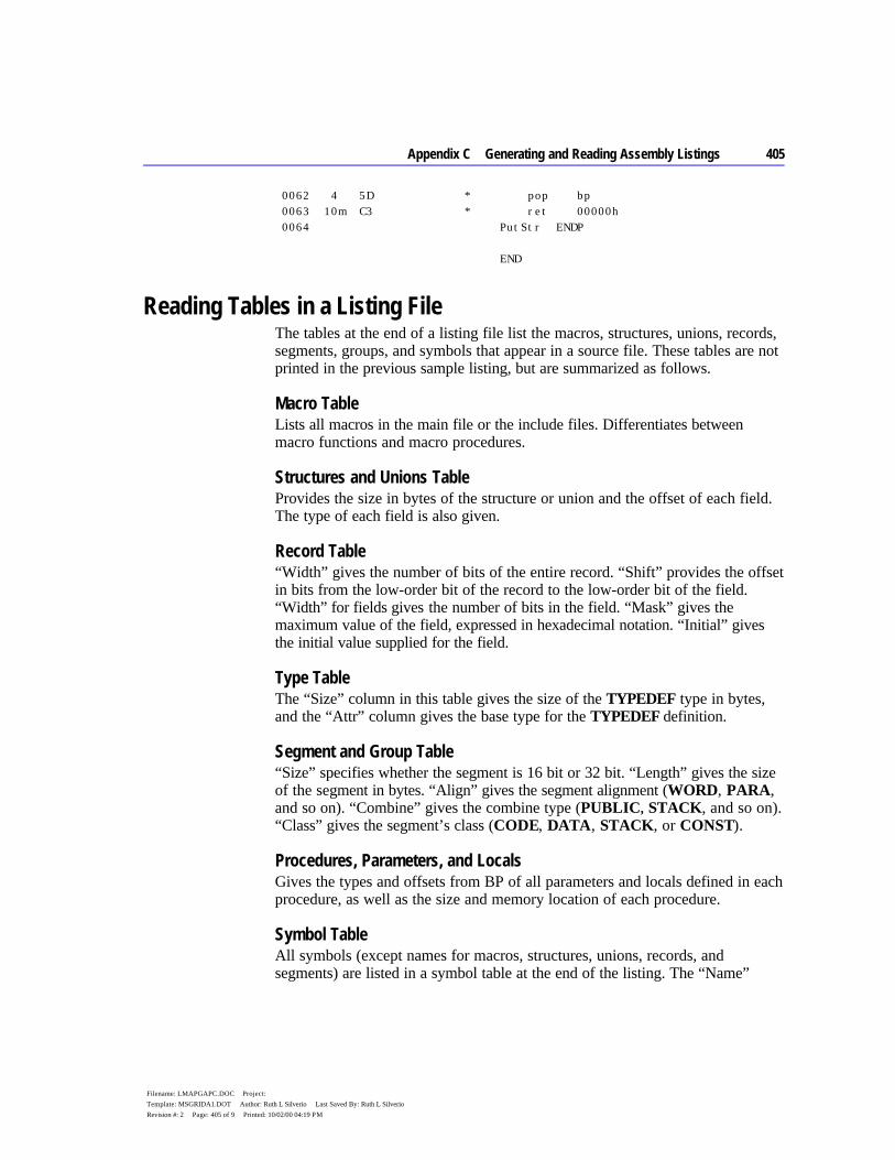
Appendix C Generating and Reading Assembly Listings 405
Filename: LMAPGAPC.DOC Project: Template: MSGRIDA1.DOT Author: Ruth L Silverio Last Saved By: Ruth L Silverio Revision #: 2 Page: 405 of 9 Printed: 10/02/00 04:19 PM
0062 4 5D * pop bp 0063 10m C3 * ret 00000h 0064 PutStr ENDP END
Reading Tables in a Listing File The tables at the end of a listing file list the macros, structures, unions, records, segments, groups, and symbols that appear in a source file. These tables are not printed in the previous sample listing, but are summarized as follows.
Macro Table Lists all macros in the main file or the include files. Differentiates between macro functions and macro procedures.
Structures and Unions Table Provides the size in bytes of the structure or union and the offset of each field. The type of each field is also given.
Record Table “Width” gives the number of bits of the entire record. “Shift” provides the offset in bits from the low-order bit of the record to the low-order bit of the field. “Width” for fields gives the number of bits in the field. “Mask” gives the maximum value of the field, expressed in hexadecimal notation. “Initial” gives the initial value supplied for the field.
Type Table The “Size” column in this table gives the size of the TYPEDEF type in bytes, and the “Attr” column gives the base type for the TYPEDEF definition.
Segment and Group Table “Size” specifies whether the segment is 16 bit or 32 bit. “Length” gives the size of the segment in bytes. “Align” gives the segment alignment (WORD, PARA, and so on). “Combine” gives the combine type (PUBLIC, STACK, and so on). “Class” gives the segment’s class (CODE, DATA, STACK, or CONST).
Procedures, Parameters, and Locals Gives the types and offsets from BP of all parameters and locals defined in each procedure, as well as the size and memory location of each procedure.
Symbol Table All symbols (except names for macros, structures, unions, records, and segments) are listed in a symbol table at the end of the listing. The “Name”
406 Programmer’s Guide
Filename: LMAPGAPC.DOC Project: Template: MSGRIDA1.DOT Author: Ruth L Silverio Last Saved By: Ruth L Silverio Revision #: 2 Page: 406 of 10 Printed: 10/02/00 04:19 PM
column lists the names in alphabetical order. The “Type” column lists each symbol’s type.
The length of a multiple-element variable, such as an array or string, is the length of a single element, not the length of the entire variable.
If the symbol represents an absolute value defined with an EQU or equal sign (=) directive, the “Value” column shows the symbol’s value. The value may be another symbol, a string, or a constant numeric value (in hexadecimal), depending on the type. If the symbol represents a variable or label, the “Value” column shows the symbol’s hexadecimal offset from the beginning of the segment in which it is defined.
The “Attr” column shows the attributes of the symbol. The attributes include the name of the segment (if any) in which the symbol is defined, the scope of the symbol, and the code length. A symbol’s scope is given only if the symbol is defined using the EXTERN and PUBLIC directives. The scope can be external, global, or communal. The “Attr” column is blank if the symbol has no attribute.


406 Programmer’s Guide
Filename: LMAPGAPC.DOC Project: Template: MSGRIDA1.DOT Author: Ruth L Silverio Last Saved By: Ruth L Silverio Revision #: 2 Page: 406 of 12 Printed: 10/02/00 04:19 PM

407
Filename: LMAPGAPD.DOC Project: Template: MSGRIDA1.DOT Author: Ruth L Silverio Last Saved By: Ruth L Silverio Revision #: 4 Page: 407 of 1 Printed: 10/02/00 04:24 PM
A P P E N D I X D
This appendix lists the reserved words recognized by MASM. They are divided primarily by their use in the language. The primary categories are:
u Operands and symbols u Registers u Operators and directives u Processor instructions u Coprocessor instructions
Reserved words in MASM 6.1 are reserved under all CPU modes. Words enabled in .8086 mode, the default, can be used in all higher CPU modes. To use words from subcategories such as “Special Operands for the 80386” (later in this appendix) requires .386 mode or higher.
You can disable the recognition of any reserved word specified in this appendix by setting the NOKEYWORD option for the OPTION directive. Once disabled, the word can be used in any way as a user-defined symbol (provided the word is a valid identifier). If you want to remove the STR instruction, the MASK operator, and the NAME directive, for instance, from the set of words MASM recognizes as reserved, add this statement to your program:
OPTION NOKEYWORD:<STR MASK NAME>
Words in this appendix identified with an asterisk (*) are new since MASM 5.1.
Operands and Symbols The words on the two lists in this section are the operands to certain directives. They have special meaning to the assembler. The words on the first list are not reserved words. They can be used in every way as normal identifiers, without affecting their use as operands to directives. The assembler interprets their use from context.
MASM Reserved Words

408 Programmer’s Guide
Filename: LMAPGAPD.DOC Project: Template: MSGRIDA1.DOT Author: Ruth L Silverio Last Saved By: Ruth L Silverio Revision #: 4 Page: 408 of 2 Printed: 10/02/00 04:24 PM
Even though the words on the first list are not reserved, they should not be defined to be text macros or text macro functions. If they are, they will not be recognized in their special contexts. The assembler does not give a warning if such a redefinition occurs.
ABS
ALL
ASSUMES
AT
CASEMAP*
COMMON
COMPACT
CPU*
DOTNAME*
EMULATOR*
EPILOGUE*
ERROR*
EXPORT*
EXPR16*
EXPR32*
FARSTACK*
FLAT
FORCEFRAME
HUGE
LANGUAGE*
LARGE
LISTING*
LJMP*
LOADDS*
M510*
MEDIUM
MEMORY
NEARSTACK*
NODOTNAME*
NOEMULATOR*
NOKEYWORD*
NOLJMP*
NOM510*
NONE
NONUNIQUE*
NOOLDMACROS*
NOOLDSTRUCTS*
NOREADONLY*
NOSCOPED*
NOSIGNEXTEND*
NOTHING
NOTPUBLIC*
OLDMACROS*
OLDSTRUCTS*
OS_DOS*
PARA
PRIVATE*
PROLOGUE*
RADIX*
READONLY*
REQ*
SCOPED*
SETIF2*
SMALL
STACK
TINY
USE16
USE32
USES
These operands are reserved words. Reserved words are not case sensitive.
$
?
@B
@F
ADDR*
BASIC
BYTE
C
CARRY?*
DWORD
FAR
FAR16*
FORTRAN
FWORD
NEAR
NEAR16*
OVERFLOW?*
PARITY?*
PASCAL
QWORD
REAL4*
REAL8*
REAL10*
SBYTE*
SDWORD*
SIGN?*
STDCALL*
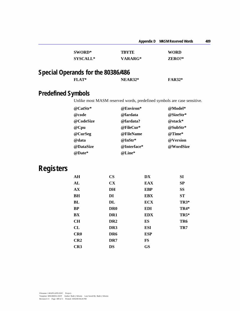
Appendix D MASM Reserved Words 409
Filename: LMAPGAPD.DOC Project: Template: MSGRIDA1.DOT Author: Ruth L Silverio Last Saved By: Ruth L Silverio Revision #: 4 Page: 409 of 3 Printed: 10/02/00 04:24 PM
SWORD*
SYSCALL*
TBYTE
VARARG*
WORD
ZERO?*
Special Operands for the 80386/486 FLAT* NEAR32* FAR32*
Predefined Symbols Unlike most MASM reserved words, predefined symbols are case sensitive.
@CatStr*
@code
@CodeSize
@Cpu
@CurSeg
@data
@DataSize
@Date*
@Environ*
@fardata
@fardata?
@FileCur*
@FileName
@InStr*
@Interface*
@Line*
@Model*
@SizeStr*
@stack*
@SubStr*
@Time*
@Version
@WordSize
Registers AH
AL
AX
BH
BL
BP
BX
CH
CL
CR0
CR2
CR3
CS
CX
DH
DI
DL
DR0
DR1
DR2
DR3
DR6
DR7
DS
DX
EAX
EBP
EBX
ECX
EDI
EDX
ES
ESI
ESP
FS
GS
SI
SP
SS
ST
TR3*
TR4*
TR5*
TR6
TR7
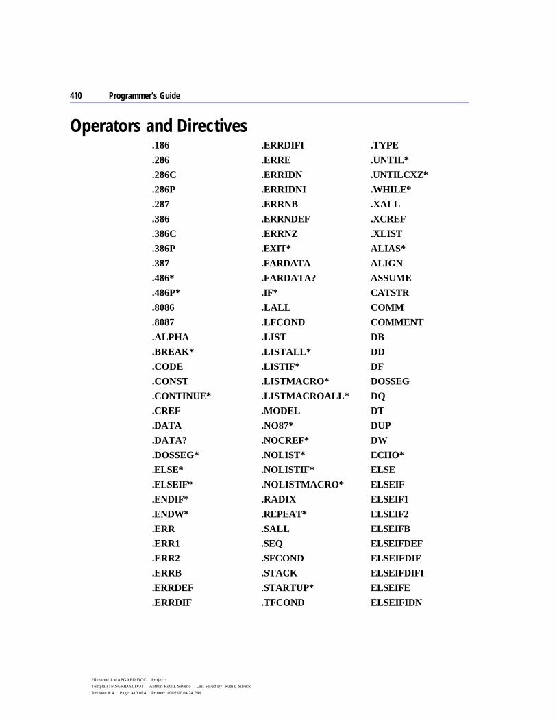
410 Programmer’s Guide
Filename: LMAPGAPD.DOC Project: Template: MSGRIDA1.DOT Author: Ruth L Silverio Last Saved By: Ruth L Silverio Revision #: 4 Page: 410 of 4 Printed: 10/02/00 04:24 PM
Operators and Directives .186
.286
.286C
.286P
.287
.386
.386C
.386P
.387
.486*
.486P*
.8086
.8087
.ALPHA
.BREAK*
.CODE
.CONST
.CONTINUE*
.CREF
.DATA
.DATA?
.DOSSEG*
.ELSE*
.ELSEIF*
.ENDIF*
.ENDW*
.ERR
.ERR1
.ERR2
.ERRB
.ERRDEF
.ERRDIF
.ERRDIFI
.ERRE
.ERRIDN
.ERRIDNI
.ERRNB
.ERRNDEF
.ERRNZ
.EXIT*
.FARDATA
.FARDATA?
.IF*
.LALL
.LFCOND
.LIST
.LISTALL*
.LISTIF*
.LISTMACRO*
.LISTMACROALL*
.MODEL
.NO87*
.NOCREF*
.NOLIST*
.NOLISTIF*
.NOLISTMACRO*
.RADIX
.REPEAT*
.SALL
.SEQ
.SFCOND
.STACK
.STARTUP*
.TFCOND
.TYPE
.UNTIL*
.UNTILCXZ*
.WHILE*
.XALL
.XCREF
.XLIST
ALIAS*
ALIGN
ASSUME
CATSTR
COMM
COMMENT
DB
DD
DF
DOSSEG
DQ
DT
DUP
DW
ECHO*
ELSE
ELSEIF
ELSEIF1
ELSEIF2
ELSEIFB
ELSEIFDEF
ELSEIFDIF
ELSEIFDIFI
ELSEIFE
ELSEIFIDN
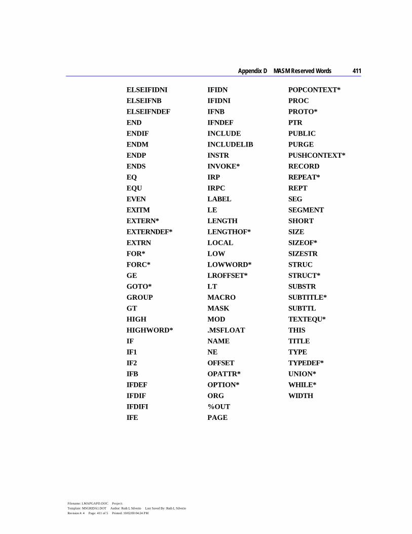
Appendix D MASM Reserved Words 411
Filename: LMAPGAPD.DOC Project: Template: MSGRIDA1.DOT Author: Ruth L Silverio Last Saved By: Ruth L Silverio Revision #: 4 Page: 411 of 5 Printed: 10/02/00 04:24 PM
ELSEIFIDNI
ELSEIFNB
ELSEIFNDEF
END
ENDIF
ENDM
ENDP
ENDS
EQ
EQU
EVEN
EXITM
EXTERN*
EXTERNDEF*
EXTRN
FOR*
FORC*
GE
GOTO*
GROUP
GT
HIGH
HIGHWORD*
IF
IF1
IF2
IFB
IFDEF
IFDIF
IFDIFI
IFE
IFIDN
IFIDNI
IFNB
IFNDEF
INCLUDE
INCLUDELIB
INSTR
INVOKE*
IRP
IRPC
LABEL
LE
LENGTH
LENGTHOF*
LOCAL
LOW
LOWWORD*
LROFFSET*
LT
MACRO
MASK
MOD
.MSFLOAT
NAME
NE
OFFSET
OPATTR*
OPTION*
ORG
%OUT
PAGE
POPCONTEXT*
PROC
PROTO*
PTR
PUBLIC
PURGE
PUSHCONTEXT*
RECORD
REPEAT*
REPT
SEG
SEGMENT
SHORT
SIZE
SIZEOF*
SIZESTR
STRUC
STRUCT*
SUBSTR
SUBTITLE*
SUBTTL
TEXTEQU*
THIS
TITLE
TYPE
TYPEDEF*
UNION*
WHILE*
WIDTH
412
Filename: LMAPGAPD.DOC Project: Template: MSGRIDA1.DOT Author: Ruth L Silverio Last Saved By: Ruth L Silverio Revision #: 4 Page: 412 of 6 Printed: 10/02/00 04:24 PM
Processor Instructions Processor instructions are not case sensitive.
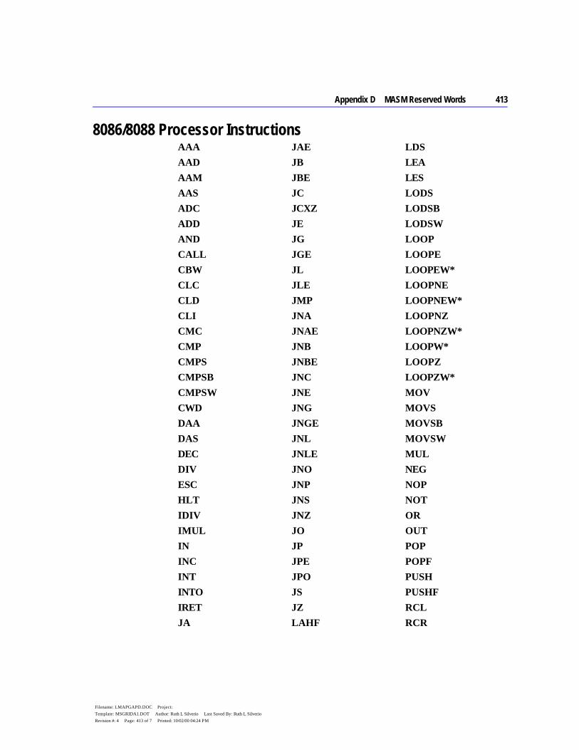
Appendix D MASM Reserved Words 413
Filename: LMAPGAPD.DOC Project: Template: MSGRIDA1.DOT Author: Ruth L Silverio Last Saved By: Ruth L Silverio Revision #: 4 Page: 413 of 7 Printed: 10/02/00 04:24 PM
8086/8088 Processor Instructions AAA
AAD
AAM
AAS
ADC
ADD
AND
CALL
CBW
CLC
CLD
CLI
CMC
CMP
CMPS
CMPSB
CMPSW
CWD
DAA
DAS
DEC
DIV
ESC
HLT
IDIV
IMUL
IN
INC
INT
INTO
IRET
JA
JAE
JB
JBE
JC
JCXZ
JE
JG
JGE
JL
JLE
JMP
JNA
JNAE
JNB
JNBE
JNC
JNE
JNG
JNGE
JNL
JNLE
JNO
JNP
JNS
JNZ
JO
JP
JPE
JPO
JS
JZ
LAHF
LDS
LEA
LES
LODS
LODSB
LODSW
LOOP
LOOPE
LOOPEW*
LOOPNE
LOOPNEW*
LOOPNZ
LOOPNZW*
LOOPW*
LOOPZ
LOOPZW*
MOV
MOVS
MOVSB
MOVSW
MUL
NEG
NOP
NOT
OR
OUT
POP
POPF
PUSH
PUSHF
RCL
RCR

414 Programmer’s Guide
Filename: LMAPGAPD.DOC Project: Template: MSGRIDA1.DOT Author: Ruth L Silverio Last Saved By: Ruth L Silverio Revision #: 4 Page: 414 of 8 Printed: 10/02/00 04:24 PM
RET
RETF
RETN
ROL
ROR
SAHF
SAL
SAR
SBB
SCAS
SCASB
SCASW
SHL
SHR
STC
STD
STI
STOS
STOSB
STOSW
SUB
TEST
WAIT
XCHG
XLAT
XLATB
XOR
80186 Processor Instructions BOUND
ENTER
INS
INSB
INSW
LEAVE
OUTS
OUTSB
OUTSW
POPA
PUSHA
PUSHW*
80286 Processor Instructions ARPL
LAR
LSL
SGDT
SIDT
SLDT
SMSW
STR
VERR
VERW
80286 and 80386 Privileged-Mode Instructions CLTS
LGDT
LIDT
LLDT
LMSW
LTR
80386 Processor Instructions BSF
BSR
BT
BTC
BTR
BTS
CDQ
CMPSD
CWDE
INSD
IRETD
IRETDF*
IRETF*
JECXZ
LFS
LGS
LODSD
LOOPD*

Appendix D MASM Reserved Words 415
Filename: LMAPGAPD.DOC Project: Template: MSGRIDA1.DOT Author: Ruth L Silverio Last Saved By: Ruth L Silverio Revision #: 4 Page: 415 of 9 Printed: 10/02/00 04:24 PM
LOOPED*
LOOPNED*
LOOPNZD*
LOOPZD*
LSS
MOVSD
MOVSX
MOVZX
OUTSD
POPAD
POPFD
PUSHAD
PUSHD*
PUSHFD
SCASD
SETA
SETAE
SETB
SETBE
SETC
SETE
SETG
SETGE
SETL
SETLE
SETNA
SETNAE
SETNB
SETNBE
SETNC
SETNE
SETNG
SETNGE
SETNL
SETNLE
SETNO
SETNP
SETNS
SETNZ
SETO
SETP
SETPE
SETPO
SETS
SETZ
SHLD
SHRD
STOSD
80486 Processor Instructions BSWAP*
CMPXCHG*
INVD*
INVLPG*
WBINVD*
XADD*
Instruction Prefixes LOCK
REP
REPE
REPNE
REPNZ
REPZ
Coprocessor Instructions Coprocessor instructions are not case sensitive.
8087 Coprocessor Instructions F2XM1
FABS
FADD
FADDP
FBLD
FBSTP
FCHS
FCLEX
FCOM
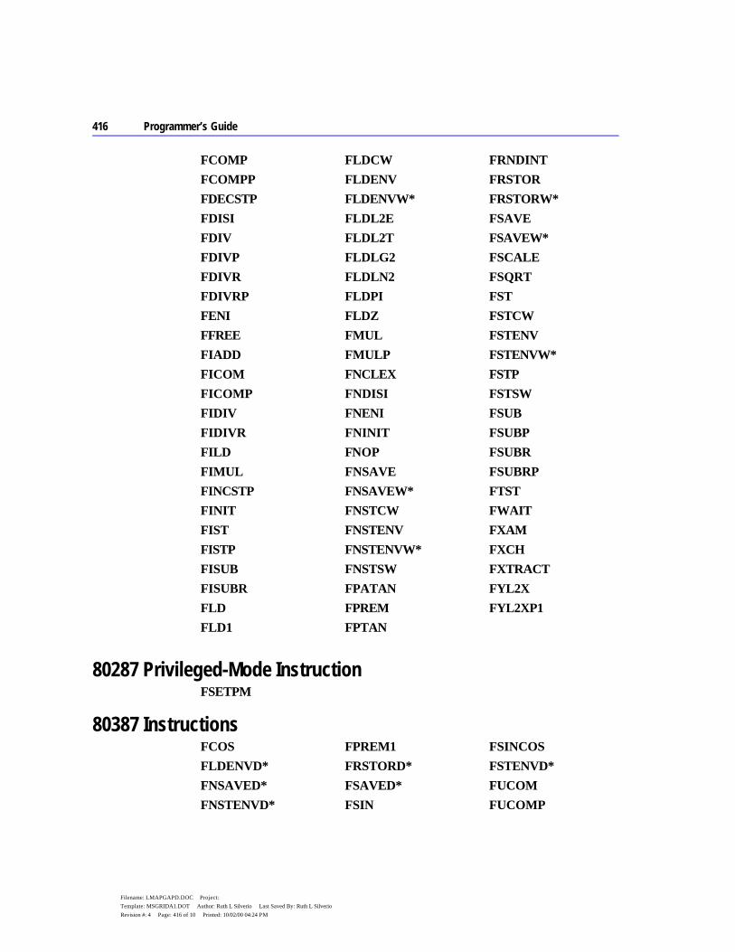
416 Programmer’s Guide
Filename: LMAPGAPD.DOC Project: Template: MSGRIDA1.DOT Author: Ruth L Silverio Last Saved By: Ruth L Silverio Revision #: 4 Page: 416 of 10 Printed: 10/02/00 04:24 PM
FCOMP
FCOMPP
FDECSTP
FDISI
FDIV
FDIVP
FDIVR
FDIVRP
FENI
FFREE
FIADD
FICOM
FICOMP
FIDIV
FIDIVR
FILD
FIMUL
FINCSTP
FINIT
FIST
FISTP
FISUB
FISUBR
FLD
FLD1
FLDCW
FLDENV
FLDENVW*
FLDL2E
FLDL2T
FLDLG2
FLDLN2
FLDPI
FLDZ
FMUL
FMULP
FNCLEX
FNDISI
FNENI
FNINIT
FNOP
FNSAVE
FNSAVEW*
FNSTCW
FNSTENV
FNSTENVW*
FNSTSW
FPATAN
FPREM
FPTAN
FRNDINT
FRSTOR
FRSTORW*
FSAVE
FSAVEW*
FSCALE
FSQRT
FST
FSTCW
FSTENV
FSTENVW*
FSTP
FSTSW
FSUB
FSUBP
FSUBR
FSUBRP
FTST
FWAIT
FXAM
FXCH
FXTRACT
FYL2X
FYL2XP1
80287 Privileged-Mode Instruction FSETPM
80387 Instructions FCOS
FLDENVD*
FNSAVED*
FNSTENVD*
FPREM1
FRSTORD*
FSAVED*
FSIN
FSINCOS
FSTENVD*
FUCOM
FUCOMP

Appendix D MASM Reserved Words 417
Filename: LMAPGAPD.DOC Project: Template: MSGRIDA1.DOT Author: Ruth L Silverio Last Saved By: Ruth L Silverio Revision #: 4 Page: 417 of 11 Printed: 10/02/00 04:24 PM
FUCOMPP
417
Filename: LMAPGAPE.DOC Project: Template: MSGRIDA1.DOT Author: Ruth L Silverio Last Saved By: Ruth L Silverio Revision #: 2 Page: 417 of 1 Printed: 10/02/00 04:24 PM
A P P E N D I X E
If you use simplified segment directives by themselves, you do not need to know the names assigned for each segment. However, it is possible to mix full segment definitions with simplified segment directives, in which case you need to know the segment names.
Table E.1 shows the default segment names created by each directive.
If you use .MODEL, a _TEXT segment is always defined, even if all .CODE directives specify a name. The default segment name used as part of far-code segment names is the filename of the module. The default name associated with the .CODE directive can be overridden, as can the default names for .FARDATA and .FARDATA?.
The segment and group table at the end of listings always shows the actual segment names. However, the GROUP and ASSUME statements generated by the .MODEL directive are not shown in listing files. For a program that uses all possible segments, group statements equivalent to the following would be generated:
DGROUP GROUP _DATA, CONST, _BSS, STACK
For the tiny model, these ASSUME statements would be generated:
ASSUME cs:DGROUP, ds:DGROUP, ss:DGROUP
For small and compact models with NEARSTACK, these ASSUME statements would be generated:
ASSUME cs: _TEXT, ds:DGROUP, ss:DGROUP
Default Segment Names

418 Programmer’s Guide
Filename: LMAPGAPE.DOC Project: Template: MSGRIDA1.DOT Author: Ruth L Silverio Last Saved By: Ruth L Silverio Revision #: 2 Page: 418 of 2 Printed: 10/02/00 04:24 PM
For medium, large, and huge models with NEARSTACK, these ASSUME statements would be generated:
ASSUME cs:name_TEXT, ds:DGROUP, ss:DGROUP
Table E.1 Default Segments and Types for Standard Memory Models
Model Directive Name Align Combine Class Group
Tiny .CODE _TEXT WORD PUBLIC 'CODE' DGROUP .FARDATA FAR_DATA PARA PRIVATE 'FAR_DATA' .FARDATA? FAR_BSS PARA PRIVATE 'FAR_BSS' .DATA _DATA WORD PUBLIC 'DATA' DGROUP .CONST CONST WORD PUBLIC 'CONST' DGROUP .DATA? _BSS WORD PUBLIC 'BSS' DGROUP
Small .CODE _TEXT WORD PUBLIC 'CODE' .FARDATA FAR_DATA PARA PRIVATE 'FAR_DATA' .FARDATA? FAR_BSS PARA PRIVATE 'FAR_BSS' .DATA _DATA WORD PUBLIC 'DATA' DGROUP .CONST CONST WORD PUBLIC 'CONST' DGROUP .DATA? _BSS WORD PUBLIC 'BSS' DGROUP .STACK STACK PARA STACK 'STACK' DGROUP*
Medium .CODE name_TEXT WORD PUBLIC 'CODE' .FARDATA FAR_DATA PARA PRIVATE 'FAR_DATA' .FARDATA? FAR_BSS PARA PRIVATE 'FAR_BSS' .DATA _DATA WORD PUBLIC 'DATA' DGROUP .CONST CONST WORD PUBLIC 'CONST' DGROUP .DATA? _BSS WORD PUBLIC 'BSS' DGROUP .STACK STACK PARA STACK 'STACK' DGROUP*
Compact .CODE _TEXT WORD PUBLIC 'CODE' .FARDATA FAR_DATA PARA PRIVATE 'FAR_DATA' .FARDATA? FAR_BSS PARA PRIVATE 'FAR_BSS' .DATA _DATA WORD PUBLIC 'DATA' DGROUP .CONST CONST WORD PUBLIC 'CONST' DGROUP .DATA? _BSS WORD PUBLIC 'BSS' DGROUP .STACK STACK PARA STACK 'STACK' DGROUP*
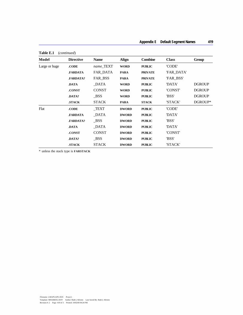
Appendix E Default Segment Names 419
Filename: LMAPGAPE.DOC Project: Template: MSGRIDA1.DOT Author: Ruth L Silverio Last Saved By: Ruth L Silverio Revision #: 2 Page: 419 of 3 Printed: 10/02/00 04:24 PM
Table E.1 (continued)
Model Directive Name Align Combine Class Group
Large or huge .CODE name_TEXT WORD PUBLIC 'CODE' .FARDATA FAR_DATA PARA PRIVATE 'FAR_DATA' .FARDATA? FAR_BSS PARA PRIVATE 'FAR_BSS' .DATA _DATA WORD PUBLIC 'DATA' DGROUP .CONST CONST WORD PUBLIC 'CONST' DGROUP .DATA? _BSS WORD PUBLIC 'BSS' DGROUP .STACK STACK PARA STACK 'STACK' DGROUP*
Flat .CODE _TEXT DWORD PUBLIC 'CODE' .FARDATA _DATA DWORD PUBLIC 'DATA' .FARDATA? _BSS DWORD PUBLIC 'BSS' .DATA _DATA DWORD PUBLIC 'DATA' .CONST CONST DWORD PUBLIC 'CONST' .DATA? _BSS DWORD PUBLIC 'BSS' .STACK STACK DWORD PUBLIC 'STACK'
* unless the stack type is FARSTACK

420 Programmer’s Guide
Filename: LMAPGAPE.DOC Project: Template: MSGRIDA1.DOT Author: Ruth L Silverio Last Saved By: Ruth L Silverio Revision #: 2 Page: 420 of 4 Printed: 10/02/00 04:24 PM
421
Filename: LMAPGGLO.DOC Project: Glossary Template: GLOSS.DOT Author: Ruth L Silverio Last Saved By: Ruth L Silverio Revision #: 2 Page: 421 of 16 Printed: 10/02/00 04:21 PM
Glossary
8087, 80287, or 80387 coprocessor Intel chips that perform high-speed floating-point and binary coded decimal number processing. Also called math coprocessors. Floating-point instructions are supported directly by the 80486 processor.
A The memory location of a data item or
procedure. The expression can represent just the offset (in which case the default segment is assumed), or it can be in segment:offset format.
In an assembly-language instruction, an immediate operand derived by applying the SEG or OFFSET operator to an identifier.
A range of memory bounded by two addresses.
The various ways a memory address or device I/O address can be generated. See “far address,” “near address.”
Data types containing more than one element, such as arrays, structures, and unions.
A debugging feature in which each line in a running program is highlighted as it executes. The Animate command from the CodeView debugger Run menu turns on animation.
API (application programming interface) A set of system-level routines that can be used in an application program for tasks such as basic input/output and file management. In a graphics-oriented operating environment like Microsoft Windows, high-level support for video graphics output is part of the Windows graphical API.
In PWB, a function modifier that introduces an argument or an editing function. The argument may be of any type and is passed to the next function as input. For example, the PWB command Arg textarg Copy passes the text argument textarg to the function Copy.
A value passed to a procedure or function. See “parameter.”
An ordered set of continuous elements of the same type.
ASCII (American Standard Code for Information Interchange) A widely used coding scheme where 1-byte numeric values represent letters, numbers, symbols, and special characters. There are 256 possible codes. The first 128 codes are standardized; the remaining 128 are special characters defined by the computer manufacturer.
A program that converts a text file containing mnemonically coded microprocessor instructions into the corresponding binary machine code. MASM is an assembler. See “compiler.”
A programming language in which each line of source code corresponds to a specific microprocessor instruction. Assembly language gives the programmer full access to the computer’s hardware and produces the most compact, fastest executing code. See “high-level language.”
The mode in which the CodeView debugger displays the assembly-language equivalent of the high-level code being executed. CodeView obtains the assembly-
address
address constant
address range
addressing modes
aggregate types
animate
arg
argument
array
assembler
assembly language
assembly mode
422 base address
Filename: LMAPGGLO.DOC Project: Glossary Template: GLOSS.DOT Author: Ruth L Silverio Last Saved By: Ruth L Silverio Revision #: 2 Page: 422 of 16 Printed: 10/02/00 04:21 PM
language code by disassembling the executable file. See “source mode.”
B The starting address of a stack
frame. Base addresses are usually stored in the BP register.
The portion of the filename that precedes the extension. For example, SAMPLE is the base name of the file SAMPLE.ASM.
A way of representing decimal digits where 4 bits of 1 byte are a decimal digit, coded as the equivalent binary number.
Referring to the base-2 counting system, whose digits are 0 and 1.
A Boolean expression consisting of two operands joined by a binary operator and resolving to a binary number.
A file that contains numbers in binary form (as opposed to ASCII characters representing the same numbers). For example, a program file is a binary file.
A Boolean operator that takes two arguments. The AND and OR operators in assembly language are examples of binary operators.
BIOS (Basic Input/Output System) The software in a computer’s ROM which forms a hardware-independent interface between the CPU and its peripherals (for example, keyboard, disk drives, video display, I/O ports).
Short for binary digit. The basic unit of binary counting. Logically equivalent to decimal digits, except that bits can have a value of 0 or 1, whereas decimal digits can range from 0 through 9.
A user-defined condition that pauses program execution while debugging. CodeView can set breakpoints at a specific line of code, for a specific value of a variable, or for a combination of these two conditions.
A reserved section of memory that holds data temporarily, most often during input/output operations.
The smallest unit of measure for computer memory and data storage. One byte consists of 8 bits and can store one 8-bit character (a letter, number, punctuation mark, or other symbol). It can represent unsigned values from 0 to 255 or signed values between –128 and +127.
C The convention that follows
the C standard for calling a procedure—that is, pushing arguments onto the stack from right to left (in reverse order from the way they appear in the argument list). The C calling convention permits a variable number of arguments to be passed.
Installing an interrupt handler that shares control of an interrupt with other handlers. Control passes from one handler to the next until a handler breaks the chain by terminating through an IRET instruction. See “interrupt handler,” “hooking (an interrupt).”
See “string.”
In PWB, a section of memory that holds text deleted with the Copy, Ldelete, or Sdelete functions. Any text attached to the clipboard deletes text already there. The Paste function inserts text from the clipboard at the current cursor position.
The filename extension for executable files that have a single segment containing both code and data. Tiny model produces .COM files.
base address
base name
BCD (binary coded decimal)
binary
binary expression
binary file
binary operator
bit
breakpoint
buffer
byte
C calling convention
chaining (to an interrupt)
character string
clipboard
.COM
device driver 423
Filename: LMAPGGLO.DOC Project: Glossary Template: GLOSS.DOT Author: Ruth L Silverio Last Saved By: Ruth L Silverio Revision #: 2 Page: 423 of 16 Printed: 10/02/00 04:21 PM
The segment-declaration specifier (AT, COMMON, MEMORY, PUBLIC, or STACK) which tells the linker to combine all segments of the same type. Segments without a combine type are private and are placed in separate physical segments.
A memory model with multiple data segments but only one code segment.
A program that translates source code into machine language. Usually applied only to high-level languages such as Basic, FORTRAN, or C. See “assembler.”
A value that does not change during program execution. A variable, on the other hand, is a value that can—and usually does—change. See “symbolic constant.”
Any expression that evaluates to a constant. It may include integer constants, character constants, floating-point constants, or other constant expressions.
D A utility program that allows the
programmer to execute a program one line at a time and view the contents of registers and memory in order to help locate the source of bugs or other problems. Examples are CodeView and Symdeb.
A construct that associates the name and the attributes of a variable, function, or type. See “variable declaration.”
A setting or value that is assumed unless specified otherwise.
A construct that initializes and allocates storage for a variable, or that specifies either code labels or the name, formal parameters, body, and return type of a procedure. See “type definition.”
A text file used as input for the NMAKE utility.
combine type
compact
compiler
constant
constant expression
debugger
declaration
default
definition
description file
424 device driver
Filename: LMAPGGLO.DOC Project: Glossary Template: GLOSS.DOT Author: Ruth L Silverio Last Saved By: Ruth L Silverio Revision #: 2 Page: 424 of 16 Printed: 10/02/00 04:21 PM
A program that transforms I/O requests into the operations necessary to make a specific piece of hardware fulfill that request.
The window at the bottom of the CodeView screen where dialog commands can be entered, and previously entered dialog commands can be reviewed.
In an assembly-language instruction, a memory operand that refers to the contents of an explicitly specified memory location.
An instruction that controls the assembler’s state.
In an assembly-language instruction, a constant value added to an effective address. This value often specifies the starting address of a variable, such as an array or multidimensional table.
See “dynamic-link library.”
To rapidly press and release a mouse button twice while pointing the mouse cursor at an object on the screen.
A real (floating-point) value that occupies 8 bytes of memory (MASM type REAL8). Double-precision values are accurate to 15 or 16 digits.
A 4-byte word (MASM type DWORD).
To move the mouse while pointing at an object and holding down one of the mouse buttons.
To display or print the contents of memory in a specified memory range.
The resolution of external references at load time or run time (rather than link time). Dynamic linking allows the called
subroutines to be packaged, distributed, and maintained independently of their callers. Windows extends the dynamic-link mechanism to serve as the primary method by which all system and nonsystem services are obtained. See “linking.”
A library file that contains the executable code for a group of dynamically linked routines.
A routine in a dynamic-link library that can be linked at load time or run time.
E A single member variable of an array of
like variables.
The section of memory containing the MS-DOS environment variables.
See “exit code.”
The filename extension for a program that can be loaded and executed by the computer. The small, compact, medium, large, huge, and flat models generate .EXE files. See “.COM,” “tiny.”
A code returned by a program to the operating system. This usually indicates whether the program ran successfully.
Increased memory available after adding an EMS (Expanded Memory Specification) board to an 8086 or 80286 machine. Expanded memory can be simulated in software. The EMS board can increase memory from 1 megabyte to 8 megabytes by swapping segments of high-end memory into lower memory. Applications must be written to the EMS standard in order to make use of expanded memory. See “extended memory.”
Any valid combination of
device driver
Dialog Command window
direct memory operand
directive
displacement
DLL
double-click
double precision
doubleword
drag
dump
dynamic linking
dynamic-link library (DLL)
dynamic-link routine
element
environment block
errorlevel code
.EXE
exit code
expanded memory
expression
forward declaration 425
Filename: LMAPGGLO.DOC Project: Glossary Template: GLOSS.DOT Author: Ruth L Silverio Last Saved By: Ruth L Silverio Revision #: 2 Page: 425 of 16 Printed: 10/02/00 04:21 PM
mathematical or logical variables, constants, strings, and operators that yields a single value.
Physical memory above 1 megabyte that can be addressed by 80286–80486 machines in protected mode. Adding a memory card adds extended memory. On 80386-based machines, extended memory can be made to simulate expanded memory by using a memory-management program.
The part of a filename (of up to three characters) that follows the period (.). An extension is not required but is usually added to differentiate similar files. For example, the source-code file MYPROG.ASM is assembled into the object file MYPROG.OBJ, which is linked to produce the executable file MYPROG.EXE.
A variable declared in one module and referenced in another module.
F A memory location specified with a
segment value plus an offset from the start of that segment. Far addresses require 4 bytes—two for the segment and two for the offset. See “near address.”
One of the components of a structure, union, or record variable.
The linking process that supplies addresses for procedure calls and variable references.
A register containing information about the status of the CPU and the results of the last arithmetic operation performed by the CPU.
A nonsegmented linear address space. Selectors in flat model can address the entire 4 gigabytes of addressable memory space. See “segment,” “selector.”
The variables that receive values passed to a function when the function is called.
extended memory
extension
external variable
far address
field
fixup
flags register
flat
formal parameters
426 forward declaration
Filename: LMAPGGLO.DOC Project: Glossary Template: GLOSS.DOT Author: Ruth L Silverio Last Saved By: Ruth L Silverio Revision #: 2 Page: 426 of 16 Printed: 10/02/00 04:21 PM
A function declaration that establishes the attributes of a symbol so that it can be referenced before it is defined, or called from a different source file.
The segment, group, or segment register that specifies the segment portion of an address.
G An error that
occurs in protected mode when a program accesses invalid memory locations or accesses valid locations in an invalid way (such as writing into ROM areas).
1,024 megabytes, or 1,073,741,824 bytes.
See “visibility.”
A constant available throughout a module. Symbolic constants defined in the module-level code are global constants.
A data segment that is shared among all instances of a dynamic-link routine; in other words, a single segment that is accessible to all processes that call a particular dynamic-link routine.
A variable that is available (visible) across multiple modules.
The degree to which library procedures can be linked as individual blocks of code. In Microsoft libraries, granularity is at the object-file level. If a single object file containing three procedures is added to a library, all three procedures will be linked with the main program even if only one of them is actually called.
A collection of individually defined segments that have the same segment base address.
H An arbitrary value that an operating
system supplies to a program (or vice versa) so that the program can access system resources, files, peripherals, and so forth, in a controlled fashion.
See “interrupt handler.”
The base-16 numbering system whose digits are 0 through F (the letters A through F represent the decimal numbers 10 through 15). This is often used in computer programming because it is easily converted to and from the binary (base-2) numbering system the computer itself uses.
A programming language that expresses operations as mathematical or logical relationships, which the language’s compiler then converts into machine code. This contrasts with assembly language, in which the program is written directly as a sequence of explicit microprocessor instructions. Basic, C, COBOL, and FORTRAN are examples of high-level languages. See “assembly language,” “compiler.”
Replacing an address in the interrupt vector table with the address of another interrupt handler. See “interrupt handler,” “interrupt vector table,” “unhooking (an interrupt).”
A memory model (similar to large model) with more than one code segment and more than one data segment. However, individual data items can be larger than 64K, spanning more than one segment. See “large.”
I A name that identifies a register or
memory location.
forward declaration
frame
General-Protection (GP) fault
gigabyte
global
global constant
global data segment
global variable
granularity
group
handle
handler
hexadecimal
high-level language
hooking (an interrupt)
huge
identifier
linked list 427
Filename: LMAPGGLO.DOC Project: Glossary Template: GLOSS.DOT Author: Ruth L Silverio Last Saved By: Ruth L Silverio Revision #: 2 Page: 427 of 16 Printed: 10/02/00 04:21 PM
A standard created by the Institute of Electrical and Electronics Engineers for representing floating-point numbers, performing math with them, and handling underflow/overflow conditions. The 8087 family of coprocessors and the emulator package implement this format.
An expression that evaluates to a number that can be either a component of an address or the entire address.
In an assembly-language instruction, a constant operand that is specified at assembly time and stored in the program file as part of the instruction opcode.
A pseudo library that contains addresses rather than executable code. The linker reads the addresses from an import library to resolve references to external dynamic-link library routines.
A text file with the .INC extension whose contents are inserted into the source-code file and immediately assembled.
In an assembly-language instruction, a memory operand whose value is treated as an address that points to the location of the desired data. See “pointer.”
The unit of binary information that a CPU decodes and executes. In assembly language, instruction refers to the mnemonic (such as LDS or SHL) that the assembler converts into machine code.
See “prefix.”
A signal to the processor to halt its current operation and immediately transfer control to an interrupt handler. Interrupts are triggered either by hardware, as when the keyboard detects a keypress, or by software, as when a program executes the INT instruction. See “interrupt handler.”
A routine that receives processor control when a specific interrupt occurs.
See “interrupt handler.”
An address that points to an interrupt handler.
A table maintained by the operating system. It contains addresses (vectors) of current interrupt handlers. When an interrupt occurs, the CPU branches to the address in the table that corresponds to the interrupt’s number. See “interrupt handler.”
K A word with a special, predefined
meaning for the assembler. Keywords cannot be used as identifiers.
1,024 bytes.
L A symbol (identifier) representing the
address of a code label or data objects.
The specifier that establishes the naming and calling conventions for a procedure. These are BASIC, C, FORTRAN, PASCAL, STDCALL, and SYSCALL.
A memory model with more than one code segment and more than one data segment, but with no individual data item larger than 64K (a single segment). See “huge.”
A file that contains modules of compiled code. MS-DOS programs use normal run-time libraries, from which the linker extracts modules and combines them with other object modules to create executable program files. Windows-based programs can use dynamic-link libraries (see), which the operating system loads and links to calling programs. See also “import library.”
IEEE format
immediate expression
immediate operand
import library
include file
indirect memory operand
instruction
instruction prefix
interrupt
interrupt handler
interrupt service routine
interrupt vector
interrupt vector table
keyword
kilobyte (K)
label
language type
large
library

428 linked list
Filename: LMAPGGLO.DOC Project: Glossary Template: GLOSS.DOT Author: Ruth L Silverio Last Saved By: Ruth L Silverio Revision #: 2 Page: 428 of 16 Printed: 10/02/00 04:21 PM
A data structure in which each entry includes a pointer to the location of the adjoining entries.
In normal static linking, the process in which the linker resolves all external references by searching run-time and user libraries, and then computes absolute offset addresses for these references. Static linking results in a single executable file. In dynamic linking (see), the operating system, rather than the linker, provides the addresses after loading the modules into separate parts of memory.
A constant whose scope is limited to a procedure or a module.
A variable whose scope is confined to a particular unit of code, such as module-level code, or a procedure. See “module-level code.”
A symbolic name for a device that can be mapped to a physical (actual) device.
A complete program statement in source code, including the initial line of code and any extension lines.
A memory area in which a program stores code, data, or stack information. See “physical segment.”
low-level input and output routines Run-time library routines that perform unbuffered, unformatted input/output operations.
The bit lowest in memory in a binary number.
M The binary numbers that a
microprocessor interprets as program instructions. See “instruction.”
A block of text or instructions that has been assigned an identifier. When the assembler sees this identifier in the source code, it substitutes the related text or instructions and assembles them.
The module containing the point where program execution begins (the program’s entry point). See “module.”
See “8087, 80287, or 80387 coprocessor.”
A memory model with multiple code segments but only one data segment.
1,024 kilobytes or 1,048,576 bytes.
One of the elements of a structure or union; also called a field.
A number through which a program can reference a location in memory.
A representation of where in memory the computer expects to find certain types of information.
A convention for specifying the number and types of code and data segments in a module. See “tiny,” “small,” “medium,” “compact,” “large,” “huge,” and “flat.”
An operand that specifies a memory location.
A prefix that modifies the subsequent PWB function.
A word, abbreviation, or acronym that replaces something too complex to remember or type easily. For example, ADC is the mnemonic for the 8086’s add-with-carry instruction. The assembler converts it into machine (binary) code, so it is not necessary to remember or calculate the binary form.
linked list
linking
local constant
local variable
logical device
logical line
logical segment
LSB (least-significant bit)
machine code
macro
main module
math coprocessor
medium
megabyte
member
memory address
memory map
memory model
memory operand
meta
mnemonic
overlay 429
Filename: LMAPGGLO.DOC Project: Glossary Template: GLOSS.DOT Author: Ruth L Silverio Last Saved By: Ruth L Silverio Revision #: 2 Page: 429 of 16 Printed: 10/02/00 04:21 PM
A discrete group of statements. Every program has at least one module (the main module). In most cases, a module is the same as a source file.
A text file containing information that the linker uses to create a Windows-based program.
Program statements within any module that are outside procedure definitions.
The bit farthest to the left in a binary number. It represents 2(n-1), where n is the number of bits in the number.
An operating system in which two or more programs, processes, or threads can execute simultaneously.
N The way the compiler or
assembler alters the name of a routine before placing it into an object file.
Acronym for “not a number.” Math coprocessors generate NANs when the result of an operation cannot be represented in IEEE format. For example, if two numbers being multiplied have a product larger than the maximum value permitted, the coprocessor returns a NAN instead of the product.
A memory location specified by the offset from the start of the value in a segment register. A near address requires only 2 bytes. See “far address.”
See “reentrant procedure.”
The ASCII character encoded as the value 0.
A pointer to nothing, expressed as
the value 0.
O Default filename extension for an object
file.
A file (normally with the extension .OBJ) produced by assembling source code. It contains relocatable machine code. The linker combines object files with run-time and library code to create an executable file.
The number of bytes from the beginning of a segment to a particular byte within that segment.
The binary number that represents a specific microprocessor instruction.
A constant or variable value that is manipulated in an expression or instruction.
One or more symbols that specify how the operand or operands of an expression are manipulated.
A variable that modifies the way a program performs. Options can appear on the command line, or they can be part of an initialization file (such as TOOLS.INI). An option is sometimes called a switch.
The CodeView screen that displays program output. Choosing the Output command from the View menu or pressing F4 switches to this screen.
An error that occurs when the value assigned to a numeric variable is larger than the allowable limit for that variable’s type.
A program component loaded into memory from disk only when needed. This technique reduces the amount of free RAM needed to run the program.
module
module-definition file
module-level code
MSB (most-significant bit)
multitasking operating system
naming convention
NAN
near address
nonreentrant
null character
null pointer
.OBJ
object file
offset
opcode
operand
operator
option
output screen
overflow
overlay

430 parameter
Filename: LMAPGGLO.DOC Project: Glossary Template: GLOSS.DOT Author: Ruth L Silverio Last Saved By: Ruth L Silverio Revision #: 2 Page: 430 of 16 Printed: 10/02/00 04:21 PM
P The name given in a procedure
definition to a variable that is passed to the procedure. See “argument.”
Transferring the address of an argument to a procedure. This allows the procedure to modify the argument’s value.
Transferring the value (rather than the address) of an argument to a procedure. This prevents the procedure from changing the argument’s original value.
The true memory address of a segment, referenced through a segment register.
A variable containing the address of another variable. See “indirect memory operand.”
The relative position of an operator in the hierarchy that determines the order in which expression elements are evaluated.
Having the power to take precedence over another event.
A keyword (LOCK, REP, REPE, REPNE, REPNZ, or REPZ) that modifies the behavior of an instruction. MASM 6.1 ensures the prefix is compatible with the instruction.
Data items and routines local to the module in which they are defined. They cannot be accessed outside that module. See “public.”
A hardware-supported feature of the 80286–80486 processors that allows the programmer to specify the exclusivity of a program or process. Programs running at low-numbered privilege levels can access data or resources at higher-numbered privilege levels, but the reverse is not true. This feature reduces the possibility that malfunctioning code will corrupt data or crash the operating system.
The term applied to privilege level 0. This privilege level should be used only by a protected-mode operating system. Special privileged instructions are enabled by .286P, .386P, and .486P. Privileged mode should not be confused with protected mode.
parameter
passing by reference
passing by value
physical segment
pointer
precedence
preemptive
prefix
private
privilege level
privileged mode
ROM (read-only memory) 431
Filename: LMAPGGLO.DOC Project: Glossary Template: GLOSS.DOT Author: Ruth L Silverio Last Saved By: Ruth L Silverio Revision #: 2 Page: 431 of 16 Printed: 10/02/00 04:21 PM
An expression that invokes a procedure and passes actual arguments (if any) to the procedure.
A definition that specifies a procedure’s name, its formal parameters, the declarations and statements that define what it does, and (optionally) its return type and storage class.
A procedure declaration that includes a list of the names and types of formal parameters following the procedure name.
Generally, any executing program or code unit. This term implies that the program or unit is one of a group of processes executing independently.
A 256-byte data structure at the base of the memory block allocated to a transient program. It contains data and addresses supplied by MS-DOS that a program can read during execution.
The 80286–80486 operating mode that permits multiple processes to run and not interfere with each other. This feature should not be confused with privileged mode.
Data items and procedures that can be accessed outside the module in which they are defined. See “private.”
Q A user-defined type consisting of
an existing MASM type (intrinsic, structure, union, or record), or a previously defined TYPEDEF type, together with its language or distance attributes.
R The base of a number system. The default
radix for MASM and CodeView is 10.
Computer memory that can be both written to and read
from. RAM data is volatile; it is usually lost when the computer is turned off. Programs are loaded into and executed from RAM. See “ROM.”
The normal operating mode of the 8086 family of processors. Addresses correspond to physical (not mapped) memory locations, and there is no mechanism to keep one application from accessing or modifying the code or data of another. See “protected mode.”
A MASM variable that consists of a sequence of bit values.
A procedure that can be safely interrupted during execution and restarted from its beginning in response to a call from a preemptive process. After servicing the preemptive call, the procedure continues execution at the point at which it was interrupted.
In an assembly-language instruction, an operand that is stored in the register specified by the instruction.
The optional CodeView window in which the CPU registers and the flag register bits are displayed.
Memory locations in the processor that temporarily store data, addresses, and processor flags.
A text expression that specifies a pattern of text to be matched (as opposed to matching specific characters).
Not having an absolute address. The assembler does not know where the label, data, or code will be located in memory, so it generates a fixup record. The linker provides the address.
The value returned by a function.
Computer memory that can only be read from and cannot be modified. ROM data is permanent; it is not lost when the
procedure call
procedure definition
procedure prototype
process
Program Segment Prefix (PSP)
protected mode
public
qualifiedtype
radix
RAM (random-access memory)
real mode
record
reentrant procedure
register operand
register window
registers
regular expression
relocatable
return value
ROM (read-only memory)
432 routine
Filename: LMAPGGLO.DOC Project: Glossary Template: GLOSS.DOT Author: Ruth L Silverio Last Saved By: Ruth L Silverio Revision #: 2 Page: 432 of 16 Printed: 10/02/00 04:21 PM
machine is turned off. A computer’s ROM often contains BIOS routines and parts of the operating system. See “RAM.”
A generic term for a procedure or function.
The act of establishing a link when a process is running. See “dynamic linking.”
A math or logic error that can be detected only when the program runs. Examples of run-time errors are dividing by a variable whose value is zero or calling a DLL function that doesn’t exist.
S The range of statements over which a
variable or constant can be referenced by name. See “global constant,” “global variable,” “local constant,” “local variable.”
A screen-exchange method that uses buffers to store the debugging and output screens. When you request the other screen, the two buffers are exchanged. This method is slower than flipping (the other screen-exchange method), but it works with most adapters and most types of programs.
The bars that appear at the right side and bottom of a window and some list boxes. Dragging the mouse on the scroll bars allows scrolling through the contents of a window or text box.
A section of memory, limited to 64K with 16-bit segments or 4 gigabytes with 32-bit segments, containing code or data. Also refers to the starting address of that memory area.
The mode in CodeView in which no windows are available. Input and output scroll down the screen, and the old output scrolls off the top of the screen when the screen is full. You cannot examine previous commands
after they scroll off the top. This mode is required with computers that are not IBM compatible.
A value that indirectly references a segment address. A protected-mode operating system, such as Windows, assigns selector values to programs, which use them as segment addresses. If a program attempts to use an unassigned selector, it triggers a General-Protection fault (see).
A memory segment that can be accessed simultaneously by more than one process.
A method of gaining access to the operating system without leaving CodeView or losing the current debugging context. It is possible to execute MS-DOS commands, then return to the debugger.
The process of widening an integer (for example, going from a byte to a word, or a word to a doubleword) while retaining its correct value and sign.
An integer value that uses the most-significant bit to represent the value’s sign. If the bit is one, the number is negative; if zero, the number is positive. See “two’s complement,” “unsigned integer,” “MSB.”
A real (floating-point) value that occupies 4 bytes of memory. Single-precision values are accurate to six or seven decimal places.
An environment in which only one program runs at a time. MS-DOS is a single-tasking environment.
A memory model with only one code segment and only one data segment.
A text file containing symbols that define the program.
The mode in which CodeView
routine
run-time dynamic linking
run-time error
scope
screen swapping
scroll bars
segment
sequential mode
selector
shared memory
shell escape
sign extended
signed integer
single precision
single-tasking environment
small
source file
source mode
status bar 433
Filename: LMAPGGLO.DOC Project: Glossary Template: GLOSS.DOT Author: Ruth L Silverio Last Saved By: Ruth L Silverio Revision #: 2 Page: 433 of 16 Printed: 10/02/00 04:21 PM
displays the assembly-language source code that represents the machine code currently being executed.
An area of memory in which data items are consecutively stored and removed on a last-in, first-out basis. A stack can be used to pass parameters to procedures.
The portion of a stack containing a particular procedure’s local variables and parameters.
A short routine called on entry to a function to verify that there is enough room in the program stack to allocate local variables required by the function.
Changing the stack pointers to point to another stack area.
A symbolic representation of the functions that are being executed to reach the current instruction address. As a function is executed, the function address and any function arguments are pushed on the stack. Therefore, tracing the stack shows the active functions and their arguments.
The device to which a program can send error messages. The display is normally standard error.
The device from which a program reads its input. The keyboard is normally standard input.
The device to which a program can send its output. The display is normally standard output.
A combination of labels, data declarations, directives, or instructions that the assembler can convert into machine code.
See “linking.”
stack
stack frame
stack probe
stack switching
stack trace
standard error
standard input
standard output
statement
status bar
434 static linking
Filename: LMAPGGLO.DOC Project: Glossary Template: GLOSS.DOT Author: Ruth L Silverio Last Saved By: Ruth L Silverio Revision #: 2 Page: 434 of 16 Printed: 10/02/00 04:21 PM
The line at the bottom of the PWB or CodeView screen. The status bar displays text position, keyboard status, current context of execution, and other program information.
A calling convention that uses caller stack cleanup if the VARARG keyword is specified. Otherwise the called routine must clean up the stack.
A contiguous sequence of characters identified with a symbolic name.
A string of characters and escape sequences delimited by single quotation marks (' ') or double quotation marks (" ").
A set of variables that may be of different types, grouped under a single name.
One of the elements of a structure. Also called a field.
See “option.”
A name that identifies a memory location (usually for data).
A constant represented by a symbol rather than the constant itself. Symbolic constants are defined with EQU statements. They make a program easier to read and modify.
A language type for a procedure. Its conventions are identical to C’s, except no underscore is prefixed to the name.
T The name assigned to a structure, union, or
enumeration type.
See “process.”
Ordinary, readable characters, including the uppercase and lowercase letters of the alphabet, the numerals 0 through 9, and punctuation marks.
In PWB, a box where you type information needed to carry out a command. A text box appears within a dialog box. The text box may be blank or contain a default entry.
Memory model with a single segment for both code and data. This limits the total program size to 64K. Tiny programs have the filename extension .COM.
A function key or menu selection that turns a feature off if it is on, or on if it is off. Used as a verb, “toggle” means to reverse the status of a feature.
A file containing initialization information for many of the Microsoft utilities, including PWB.
A form of base-2 notation in which negative numbers are formed by inverting the bit values of the equivalent positive number and adding 1 to the result.
A description of a set of values and a valid set of operations on items of that type. For example, a variable of type BYTE can have any of a set of integer values within the range specified for the type on a particular machine.
An operation in which the assembler verifies that the operands of an operator are valid or that the actual arguments in a function call are of the same types as the function definition’s parameters.
The storage format and attributes for a data unit.
U An expression consisting of a
single operand preceded or followed by a unary operator.
An operator that acts on a single operand, such as NOT.
static linking
STDCALL
string
string literal
structure
structure member
switch
symbol
symbolic constant
SYSCALL
tag
task
text
text box
tiny
toggle
TOOLS.INI
two’s complement
type
type checking
type definition
unary expression
unary operator
word 435
Filename: LMAPGGLO.DOC Project: Glossary Template: GLOSS.DOT Author: Ruth L Silverio Last Saved By: Ruth L Silverio Revision #: 2 Page: 435 of 16 Printed: 10/02/00 04:21 PM
An error condition that occurs when a calculation produces a result too small for the computer to represent.
The act of removing your interrupt handler and restoring the original vector. See “hooking (an interrupt).”
A set of values (in fields) of different types that occupy the same storage space.
See “unresolved reference.”
A reference to a global or external variable or function that cannot be found, either in the modules being linked or in the libraries linked with those modules. An unresolved reference causes a fatal link error.
An integer in which the most-significant bit serves as part of the number, rather than as an indication of sign. For example, an unsigned byte integer can have a value from 0 to 255. A signed byte integer, which reserves its eighth bit for the sign, can range from -127 to +128. See “signed integer,” “MSB.”
A data type defined by the user. It is usually a structure, union, record, or pointer.
V A statement that initializes
and allocates storage for a variable of a given type.
A portion of the computer’s random access memory reserved for use as a simulated disk drive. Also called an electronic disk or RAM disk. Unless saved to a physical disk, the contents of a virtual disk are lost when the computer is turned off.
Memory space allocated on a disk, rather than in RAM. Virtual memory allows large data structures that would not fit in conventional memory, at the expense of slow access.
The characteristic of a variable or function that describes the parts of the program in which it can be accessed. An item has global visibility if it can be referenced in every source file constituting the program. Otherwise, it has local visibility.
W The window in CodeView that
displays watch statements and their values. A variable or expression is watchable only while execution is occurring in the section of the program (context) in which the item is defined.
A discrete area of the screen in PWB or CodeView used to display part of a file or to enter statements.
Commands that work only in CodeView’s window mode. Window commands consist of function keys, mouse selections, CTRL and ALT key combinations, and selections from pop-up menus.
The mode in which CodeView displays separate windows, which can change independently. CodeView has mouse support and a wide variety of window commands in window mode.
A data unit containing 16 bits (2 bytes). It can store values from 0 to 65,535 (or -32,768 to +32,767).
underflow
unhooking (an interrupt)
union
unresolved external
unresolved reference
unsigned integer
user-defined type
variable declaration
virtual disk
virtual memory
visibility
watch window
window
window commands
window mode
word

436
Filename: LMAPGGLO.DOC Project: Glossary Template: GLOSS.DOT Author: Ruth L Silverio Last Saved By: Ruth L Silverio Revision #: 2 Page: 436 of 16 Printed: 10/02/00 04:21 PM
435
Filename: LMAPGINX.DOC Project: Template: INDEX.DOT Author: Samuel G. Dawson Last Saved By: Ruth L Silverio Revision #: 20 Page: 435 of 1 Printed: 10/02/00 04:20 PM
Index
! (literal-character operator) 235 != (not equal operator) 178 ” (double quotation marks) 109, 353 $ (current address operator) 368 % (expansion operator) 235, 248, 357 & (substitution operator) 238, 372 && (logical AND operator) 178 ’ (single quotation mark) 109, 353 ( ) (parentheses) 106 + (plus operator) 63, 66, 352, 370 . (dot operator) 126 . (structure-member operator) 64, 67, 352, 370 .186 directive 38 .286 directive 38 .286P directive 38 .287 directive 38 .386 directive
FLAT, with 26, 36 processor mode, specifying 38, 336 segment mode, setting 46, 68
.386P directive 38
.387 directive 38
.486 directive FLAT, with 36 processor mode, specifying 38 segment mode, setting 46, 68
.486P directive 38
.8087 directive 38 : (colon) 22, 352, 354 : (segment-override operator) 50, 59– 60, 64 :: (double colon) 197, 215, 352– 354 ; (semicolon) 21 ;; (double semicolon) 227 < (less than operator) 178 < > (angle brackets) See Angle brackets = = (equal operator) 178 > (greater than operator) 178 ? (question mark initializer)
array elements 109 described 368 variables 87
@ (at sign) 10 @@: (anonymous label) 170 [ ] (brackets) 107 [ ] (index operator) 63 \ (backslash character), MASM code 22 \ (line-continuation character) 121 {} (curly braces) 121, 131
|| (logical OR operator) 178 32-bit programming 335 80186 processor 3 80188 processor 3 80286 processor 3 80287 math coprocessor 3, 135 80386 processor 3, 335 80387 math coprocessor 3, 135 80486 processor 3, 135 8086-based processors 2– 3 8087 math coprocessor 3, 135 8088 processor 3
A AAD instruction 160 AAM instruction 160 ABS operand 220 Accessing data with pointers See Pointer variables ADC instruction 92– 94 ADD instruction 92– 94 ADDR operator 197 Addresses
displacement of 65 dynamic 79 effective 65 errors in 54 far 57, 74, 80 near 57, 80 physical 7 registers, loading into 80 relocatable 57 segmented 7– 8, 53
Addressing direct registers, used in 62– 63 indirect registers, used in 65, 68 scaling operands 70 specifying 60
Aliases 87, 369 ALIGN directive 3 Align types 45
See also individual entries .ALPHA directive 47 AND instruction 27, 99, 100 Angle brackets (< >)
default parameters 230 epilogues 202 FOR loops 242

436 Index
Filename: LMAPGINX.DOC Project: Template: INDEX.DOT Author: Samuel G. Dawson Last Saved By: Ruth L Silverio Revision #: 20 Page: 436 of 2 Printed: 10/02/00 04:20 PM
FORC loops 244
Index 437
Filename: LMAPGINX.DOC Project: Template: INDEX.DOT Author: Samuel G. Dawson Last Saved By: Ruth L Silverio Revision #: 20 Page: 437 of 3 Printed: 10/02/00 04:20 PM
Angle brackets (< >) (continued) macro text delimiters 234 prologues 202 records 131 structures and unions 121 Anonymous label (@@) 170
API (Application Programming Interface) 257 Architecture, segmented 2, 5 Architecture, unsegmented 5 Arguments
errors 196 macro 252 mixed-language programs, passing in 314 qualifiedtypes, with 16 stack, on 182
Arrays accessing elements in 105 declaring 105 defined 105 defining 15 DUP, declaring with 106, 124 instructions for processing 110 length of 108 multiple-line declarations for 105 number of bytes in 108 referencing 108, 316 size of elements 108 with DUP operator See DUP operator with SIZEOF operator See SIZEOF operator with TYPE operator See TYPE operator
ASCIIZ 267 Assembly
actions during 23 conditional See Conditional assembly INCLUDE files 212 language
book list xviii mixed-language programs 312
listing files See Listing files two-pass 358
Assembly pointers See Conditional assembly Assembly-time variables 233 ASSUME directive
.MODEL, generated with 37 code segments, changing 357 enhancements 344 general-purpose registers 77 segment registers, setting 49– 55, 58– 59, 357
AT address combine type 46 /AT command-line option, ML 36 At sign (@) 10
438 Index
Filename: LMAPGINX.DOC Project: Template: INDEX.DOT Author: Samuel G. Dawson Last Saved By: Ruth L Silverio Revision #: 20 Page: 438 of 4 Printed: 10/02/00 04:20 PM
B Backslash character (\) 22 Backus-Naur Form See BNF grammar Base Pointer (BP) register 73 Basic calling conventions 308– 310 Basic/MASM programs 328– 332 Binary Coded Decimals
calculating with 156– 160 defining 156 instructions for 156– 160 packed 158 unpacked 159– 160
Bits mask 99– 102 rotating 100 shifting 100
BNF grammar 16, 379– 380 BOUND instruction 108, 204 BP (Base Pointer) register 73 Brackets ([ ]) 107 .BREAK directive 173, 176 BSF instruction 100 BSR instruction 100 BYTE
align type 45 directive 86
C C calling convention 309 C++/MASM programs 322– 323 C/MASM programs 315– 321 CALL instruction 180 Calling conventions 309
Basic 308– 310 directives, specifying 37 FORTRAN 308– 310 (list) 308 mixed-language programming 308– 309 Pascal 310 STDCALL 311 SYSCALL 308– 311
CARRY? flag as operand 178 Case sensitivity
enforcing 348 macro functions, predefined 245 MASM statements 22 radix specifiers 11 reserved words 9, 407 specifying
command-line options, in 25 language type 348
OPTION directive 25

Index 439
Filename: LMAPGINX.DOC Project: Template: INDEX.DOT Author: Samuel G. Dawson Last Saved By: Ruth L Silverio Revision #: 20 Page: 439 of 5 Printed: 10/02/00 04:20 PM
Case sensitivity (continued) symbols, predefined 10
CASEMAP ALL argument, OPTION directive 25 NONE argument, OPTION directive 25 NOTPUBLIC argument, OPTION directive 25
CATSTR directive 245– 247 CATSTR, compared with TEXTEQU directive See
TEXTEQU directive @CatStr predefined string function 245– 247 CBW instruction 90 CDQ instruction 90 CLC instruction 104 Cleaning the stack 185 CLI instruction 5, 209 Client program 257, 266 CMC instruction 104 CMP instruction 166 CMPS instruction 110– 114, 353 CMPSB instruction 114 .CODE directive 33, 40– 42 Code segment See Segments, code Code, near or far 57 @CodeSize predefined symbol 40 CodeView for Windows 264 Combine types
(list) 46 See also individual entries
.COM files relocatable segment expression, lacking 62 starting address 56 tiny model, using 36, 46– 47
COMM directive 16, 211, 217– 218 Command-line driver, ML xvi Command-line options See ML command-line options COMMENT directive 22 Comments
extended lines, in 346 macros, in 227 source code 21– 22
COMMON combine type 46 Communal variables 217 Compact model See Memory models, compact Compatibility, MASM 5.1 See MASM 5.1 compatibility Conditional assembly
assembly behavior, changing 23 conditions, testing for 28 directives 28 pointers 83, 187
Conditional-error directives (table) 29 Conditional jumps 164– 170 Conditions, testing for conditional assembly See Conditional
assembly
Constants defined 11 expressions 12 immediate 61 integer 11– 12 size 363 size of 12 symbolic 12
.CONST directive 33, 39– 40
.CONTINUE directive 173, 176 Coprocessors
architecture 140– 144 control registers 156 data format in registers 140 defined 135 described 3, 139 instructions
arithmetic 148– 150 data transfer 146 described 146 (list) 414 overview 141 program control 151– 155
memory access 145 operand formats
classical stack 141 memory 142 overview 141 register 143 register-pop 144
specifying 37, 140 status word register 156 steps for using 145
/Cp command-line option, ML 10, 245 @Cpu predefined symbol 254 Curly braces ({})
records 131 structures and unions 121
Current address operator ($) 368 @CurSeg predefined symbol 39, 219 CWD instruction 90 CWDE instruction 90 /Cx command-line option, ML 158
D DAA instruction 162 DAS instruction 162 .DATA directive 33, 39– 40 .DATA? directive 33, 39– 40 @data predefined symbol 39 Data segment See Segments, data @DataSize predefined symbol 39, 83

440 Index
Filename: LMAPGINX.DOC Project: Template: INDEX.DOT Author: Samuel G. Dawson Last Saved By: Ruth L Silverio Revision #: 20 Page: 440 of 6 Printed: 10/02/00 04:20 PM

Index 441
Filename: LMAPGINX.DOC Project: Template: INDEX.DOT Author: Samuel G. Dawson Last Saved By: Ruth L Silverio Revision #: 20 Page: 441 of 7 Printed: 10/02/00 04:20 PM
Data types arrays See Arrays attributes for 15 Binary Coded Decimals 159 defined 14 defining 87 directives 14 floating-point 136 initializers, as 14 integers, allocating memory for 85– 86 new features, MASM 6.1 344 qualifiedtypes 15, 214 real 14, 136 signed 14, 86 strings See Strings structures 117 unions 117 user-defined 15
Data, near or far 57, 58 Data-sharing methods 211 Data-sharing methods, multiple-module programs See
Multiple-module programs Date, system 11 DB directive 86 DD directive 86 DEC instruction 92– 94 DF directive 86 DGROUP group name
.MODEL, defined by 34, 39, 51 DS registers, initializing to 56 MS-DOS programs, for 41– 42 near data, accessing 57– 58 segment 35– 37, 51– 52, 57
Direct memory operands loading offset of 82 overview 60– 64
Directives .286P 38 .287 38 .386 See .386 directive .386P 38 .387 38 .486P 38 .8087 38 .ALPHA 47 ALIGN 3 .BREAK 173, 176 BYTE 86 CATSTR 245– 247 .CODE 33, 40– 42 COMM 16, 211, 217– 218 COMMENT 22 Conditional assembly 28 Conditional error 29, 358
442 Index
Filename: LMAPGINX.DOC Project: Template: INDEX.DOT Author: Samuel G. Dawson Last Saved By: Ruth L Silverio Revision #: 20 Page: 442 of 8 Printed: 10/02/00 04:20 PM
Directives (continued) .CONST 33, 39– 40 .CONTINUE 173, 176 .DATA 33, 39– 40 .DATA? 33, 39– 40 Data declarations, for 87 Data types, for 14 Data-sharing See EXTERN directive DB 86 DD 86, 136 Decision 171 DF 86 .DOSSEG 47 DQ 86, 136 DT 86, 136 DW 86 DWORD 86 ECHO 236 .ELSE 171 ELSE 28 .ELSEIF 171 ELSEIF 28 ELSEIF1 29, 358 ELSEIF2 29, 358 END 33, 56 .ENDIF 171 ENDIF 28 ENDM 227– 239 ENDP 180– 181, 206 ENDS 44 .ENDW 173 EQU 12, 369 .ERR 30 .ERR1 30, 358 .ERR2 30, 358 .ERRB 30, 231 .ERRDEF 30 .ERRDIF 30 .ERRE 30 .ERRIDN 29 .ERRNB 29, 231 .ERRNDEF 29 .ERRNZ 29 EVEN 3 .EXIT 33, 41– 43 EXITM 248 EXTERN See EXTERN directive EXTERNDEF See EXTERNDEF directive FARDATA 33, 39– 40 .FARDATA 39– 40 .FARDATA? 33, 39– 40 Floating-point 136 FOR 242– 243, 249 FORC 244
Index 443
Filename: LMAPGINX.DOC Project: Template: INDEX.DOT Author: Samuel G. Dawson Last Saved By: Ruth L Silverio Revision #: 20 Page: 443 of 9 Printed: 10/02/00 04:20 PM
Directives (continued) FWORD 86 GROUP 51– 52 .IF 171 IF 28– 29 IF1 29, 358 IF2 29, 358 IFB 29, 231 IFDEF 29, 359 IFDIF 29 IFE 29 IFIDN 29 IFNB 29, 231 IFNDEF 29, 359 INCLUDE 212 INCLUDELIB 222 INSTR 245– 246 INVOKE See INVOKE directive LABEL 16 LOCAL 188– 191, 232 loop-generating 173 .MODEL See .MODEL directive .MSFLOAT 361 Naming conventions 37 .NO87 38, 349 obsolete 361 OPTION See OPTION directive ORG 56 POPCONTEXT 255, 349 PROC 180– 184, 193, 206, 312 PUBLIC 185, 211, 220 PUSHCONTEXT 255, 349 QWORD 86 .RADIX 11 REAL4 136– 137 REAL8 136– 137 REAL10 136– 137 RECORD 130– 131 Renamed since MASM 5.1 350 .REPEAT 173– 177 REPEAT 240 SBYTE 86 SDWORD 86 SEGMENT 44– 47 Segment order, controlling 47 .SEQ 47 SIZESTR 245– 246 STACK See STACK directive .STARTUP See .STARTUP directive STARTUP See .STARTUP directive STRUCT 118– 129 SUBSTR 245– 246 SWORD 86 TBYTE 86, 159

444 Index
Filename: LMAPGINX.DOC Project: Template: INDEX.DOT Author: Samuel G. Dawson Last Saved By: Ruth L Silverio Revision #: 20 Page: 444 of 10 Printed: 10/02/00 04:20 PM
Directives (continued) TEXTEQU See TEXTEQU directive UNION 118– 119, 122, 125– 129 .UNTIL 173 .UNTILCXZ 173 .WHILE 173– 177 WHILE 241 WORD 86
Directives: 36– 38, 46 Displacement 66 Distance attributes 15 DIV instruction 97– 98 Division 97, 102 DLLs
client program 257, 266 data segment 265– 269 defined 257, 266 example 267– 268 extension name 266 heap 261– 262, 265– 267 IMPLIB utility 258 initialization 261– 262, 268– 269 loading 258– 260 programming requirements 260– 261, 267 prologue and epilogue 264– 267 stacks in 46, 264– 267 summary 266 termination 262– 264, 270
Document conventions vii DOS See MS-DOS .DOSSEG directive 47 Dot (.) operator See Structure-member operator DOTNAME argument, OPTION directive 25 Double colon (::) 197, 215 Double quotation marks (”) 109 Double semicolon (;;) 227 Doublewords 86 DQ directive 86 DT directive 86 DUP operator
arrays, with 106, 124 record variables, with 131 structures and unions, with 121
DW directive 86 DWORD
align type 45 directive 86
Dynamic -link libraries See DLLs
E ECHO directive 236 .ELSE directive 171
ELSE directive 28
Index 445
Filename: LMAPGINX.DOC Project: Template: INDEX.DOT Author: Samuel G. Dawson Last Saved By: Ruth L Silverio Revision #: 20 Page: 445 of 11 Printed: 10/02/00 04:20 PM
.ELSEIF directive 171 ELSEIF directive 28 ELSEIF1 directive 358 ELSEIF2 directive 29, 358 EMULATOR argument, OPTION directive 27, 157 Emulator libraries 155– 156 END directive 33, 56 .ENDIF directive 171 ENDIF directive 28 ENDM directive 227– 239 ENDP directive 180– 181, 206 ENDS directive 44 .ENDW directive 173 ENTER instruction 183 Environment
target 4 variables
INCLUDE 213 LIB 222 returning values of 10
/EP command-line option, ML 342 EPILOGUE argument, OPTION directive 26, 201– 203 Epilogue code
defined 198 macros 201– 202, 264– 265 PROC statement, specifying arguments in 185 procedures, with 26 RET instruction 357 standard 199 user-defined 201
EQ operator 365 EQU directive 12, 369 Equal directive (=) 12 Equates, predefined See Predefined symbols .ERR directive 29 .ERR1 directive 30, 358 .ERR2 directive 30, 358 .ERRB directive 29, 231 .ERRDEF directive 29 .ERRDIF directive 29 .ERRE directive 29 .ERRIDN directive 29 .ERRNB directive 29, 231 .ERRNDEF directive 29 .ERRNZ directive 29 Error detection 196 ERROR operand 49–50 Errors, argument passing 196 ESC instruction 360 EVEN directive 3 Executable (.EXE) files, controlling size of 223 Exit codes, Windows operating system 263 .EXIT directive 33, 41– 43 EXITM directive 248
446 Index
Filename: LMAPGINX.DOC Project: Template: INDEX.DOT Author: Samuel G. Dawson Last Saved By: Ruth L Silverio Revision #: 20 Page: 446 of 12 Printed: 10/02/00 04:20 PM
Expansion operator (%) 235– 236, 248, 357 Explicit loading 258 Exponent bias 139 EXPORT operand 185 EXPORTS statement 261, 270 EXPR16 argument, OPTION directive 13, 26, 361, 373 EXPR32 argument, OPTION directive 13, 26, 373 Expression operators 178 Expressions
assembly-time evaluation 23 constant 12 loop conditions, evaluating 179 OPTION M510 behavior 364, 373 order of evaluation 14 size 366, 373 word size 13, 26
Extension, filename 266 EXTERN directive
data-sharing 211 executable file size, limiting 223 module-specific 220 overview 16 positioning 218 procedure prototypes, declaring 193
External declarations 216– 218 External variables 217, 369 EXTERNDEF directive
data-sharing 211 overview 16 positioning 218 procedure prototypes, declaring 193 symbols, declaring 214– 215
F Far addresses, invoking 57, 74, 80– 81, 197 Far code 57 Far data 58– 60 .FARDATA directive 33, 39– 40 .FARDATA? directive 39– 40 FAR operator 169, 185 Far pointer 74, 80– 81 FARSTACK operand
example 35 grouping 34 in Windows-based programs 266 MS-DOS program, initializing 43 special cases, setting for 37
Farwords 86 FCOM instruction 153 Fields, statements in 21– 22 Files
.COM
relocatable segment expression, lacking 62

Index 447
Filename: LMAPGINX.DOC Project: Template: INDEX.DOT Author: Samuel G. Dawson Last Saved By: Ruth L Silverio Revision #: 20 Page: 447 of 13 Printed: 10/02/00 04:20 PM
Files (continued) .COM (continued)
starting address 56 tiny model, using 36, 46– 47
executable 24 include 212– 213, 348 line numbers 11 naming 11
Flags CARRY? 178 operands, as 178 OVERFLOW? 178 PARITY? 178 SIGN? 178 stack, saving on 73 ZERO? 178
Flags register See Registers, flags Flat model See Memory models, flat FLAT operand 46, 49– 50 FLD1 instruction 147 FLDZ instruction 147 Floating-point
calculations 3 constants
decimal form 137 encoded hexadecimal format 137 syntax for defining 136
emulation 157– 158 IEEE format 139 instructions
arithmetic 148– 149 controlling 26 data transfer 147 not emulated (list) 158 program control 152– 153, 156
operations 146 values
double precision 139 single precision 139
variables IEEE format 138 Microsoft binary format 138 .MSFLOAT format 138 ranges 136
FOR directive 242– 243, 249 FORC directive 244 FORCEFRAME operand 200– 201 FORTRAN calling convention 308– 310 FORTRAN/MASM programs 323– 326 /Fpi command-line option, ML 26, 157 Frame 62 FS register 17 FTST instruction 153

448 Index
Filename: LMAPGINX.DOC Project: Template: INDEX.DOT Author: Samuel G. Dawson Last Saved By: Ruth L Silverio Revision #: 20 Page: 448 of 14 Printed: 10/02/00 04:20 PM
Full segment definitions described 32 segment registers, initializing 54– 56 using 44– 51
Full segment defintions See .STARTUP directive FWORD directive 86 FXCH instruction 144
G Global variables 211 GROUP directive 51– 52 Groups
defined 51 DGROUP 51 SEG operator, returned by 62
GS register 17
H H2INC 318 Heap space 261– 262, 265– 267 HEAPSIZE statement 261, 271 Help, online See Microsoft Advisor HIGH operator 356 HIGHWORD operator 346 Huge model See Memory models, huge
I /I command-line option, ML 213 Identifiers
ABS, using 220 naming restrictions 9, 346, 353, 357, 368 OPTION DOTNAME 373 OPTION NOKEYWORD 376
IDIV instruction 97– 98 IEEE format 139 .IF directive 171 IF directive 28– 29 IF1 directive 29, 358 IF2 directive 29, 358 IFB directive 29, 231 IFDEF directive 29, 359 IFDIF directive 29 IFE directive 29 IFIDN directive 29 IFNB directive 29, 231 IFNDEF directive 29, 359 Immediate operands 60– 62 IMPLIB utility 258 Implicit loading 258 Import libraries 258
Index 449
Filename: LMAPGINX.DOC Project: Template: INDEX.DOT Author: Samuel G. Dawson Last Saved By: Ruth L Silverio Revision #: 20 Page: 449 of 15 Printed: 10/02/00 04:20 PM
IMPORTS statement 266 IMUL instruction 95– 96 IN instruction 5 INC instruction 92– 94 INCLUDE directive 212 INCLUDE environment variable 213 Include files
assembling 213 nested 213 overview 212, 348
INCLUDELIB directive 222 Index operator ([ ]) 63 Indirect memory operands 60, 64– 70 Indirect procedure calls See INVOKE directive Initializers
allocating 87 directives for 15 multiple-line 346
Instance 261, 266 INSTR directive 245– 246 @InStr predefined string function 245– 246 Instruction Pointer (IP) register 20, 57, 161 Instructions
ADC 92– 94 ADD 92– 94 AND 26, 99– 100 arithmetic 378 bit-test 354 BOUND 108, 204 BSF 100 BSR 100 CALL 180 CBW 90 CDQ 90 CLC 104 CLI 5, 209 CMC 104 CMP 166 CMPS 110– 114, 353 CMPSB 114 conditional-jump 165– 167 coprocessor 377 CWD 90 CWDE 90 DAA 162 DAS 162 DEC 92– 94 default segments, requiring 49 DIV 97– 98 encodings, changes to 377– 378 ENTER 183 ESC 360 FCOM 153 FLD1 147
Instructions (continued) FLDZ 147 floating-point See Floating-point instructions FTST 153 FXCH 144 IDIV 97– 98 IMUL 95– 96 IN 5 INC 92– 94 INT 204– 205 INTO 207 JCXZ 170– 173 JECXZ 170– 173 JMP 49, 162 JO 165 jump 165–167, 170, 173 LAHF 73 LDS 81 LEA 82, 104 LEAVE 183 LES 81 (list) 412 LOCK 353, 363 LODS 110– 115, 353 logical 99– 102 LOOP 172 LOOPE 172 LOOPNE 172 LOOPNZ 172 LOOPZ 172 MOV 49, 82, 89 MOVS 110– 113, 353 MOVSX 92 MOVZX 92 MUL 95– 96 NOP 377 NOT 99– 100 obsolete 360 operands for 60 OR 26, 99– 100, 168 OUT 5 POP 49, 71 POPA 74 POPAD 74 POPF 73 POPFD 73 privileged 2, 38 PUSH 49, 71 PUSHA 74 PUSHAD 74 PUSHF 73 PUSHFD 73 RCL 101– 104 RCR 101– 104
450 Index
Filename: LMAPGINX.DOC Project: Template: INDEX.DOT Author: Samuel G. Dawson Last Saved By: Ruth L Silverio Revision #: 20 Page: 450 of 16 Printed: 10/02/00 04:20 PM
Instructions (continued) REP 110– 112, 363 REPE 110– 112, 363 REPNE 110– 112, 353, 363 REPNZ 110– 112, 353, 363 REPZ 110– 112, 363 RET 378 RETF 181, 378 RETN 181, 378 ROL 101– 104 ROR 101– 104 SAL 101– 104 SAR 101– 104 SBB 92– 94 SCAS 110– 115, 353 SHL 101– 104 SHR 101– 104 STC 104 STI 5, 209 STOS 110– 113, 353 SUB 92– 94 TEST 167– 168 timing xvii, 399– 400 XCHG 90 XLAT 116 XLATB 116 XOR 26, 99– 100
Integers adding 92– 94 allocating memory for 85– 86 Binary Coded Decimal (BCD) 159 bit operations on 99 constants, defining 11– 12 dividing 97– 98 exchanging 90 hexadecimal 12 initializing 87 memory format 86 moving 89 multiplying 95– 96 operations with 88 popping off stack 71 pushing onto stack 71 radix specifiers for 11 sign-extending 90 signed 86 size of 86 stack 71 subtracting 92– 94 translating 116 types, defining 14, 86 value range 86
@Interface predefined symbol 37 Interrupt vector 205

Index 451
Filename: LMAPGINX.DOC Project: Template: INDEX.DOT Author: Samuel G. Dawson Last Saved By: Ruth L Silverio Revision #: 20 Page: 451 of 17 Printed: 10/02/00 04:20 PM
Interrupt-enable flag 205 Interrupts
CLI instruction 209 handlers 206– 207 INT instruction 204– 205 MS-DOS 204, 285 operation 206 overview 204 redefining 207 STI instruction 209 vector table 205
INTO instruction 207 INVOKE directive
actions 194 ADDR, invoking 197 arguments, widening 196 error detection 196 far addresses, invoking 197 generated code, checking 198 indirect procedure calls 198 mixed-language programs 312– 313 procedures, calling 193– 197, 216 type conversions 194– 195
J JCXZ instruction 170– 173 JECXZ instruction 170– 173 JMP instruction 49, 162 JO instruction 165 Jumps
anonymous 170 automatic 169 conditional
bit status 167 comparisons 166 extending 26, 169 flag status 165– 166 instructions (list) 165– 167 overview 164 zero value 168
directives for 171 extension, automatic 26, 169 instructions 165– 167 optimization, automatic 162 overview 161 unconditional
indirect operands 163 jump tables 163 overview 162
L LABEL directive 16
452 Index
Filename: LMAPGINX.DOC Project: Template: INDEX.DOT Author: Samuel G. Dawson Last Saved By: Ruth L Silverio Revision #: 20 Page: 452 of 18 Printed: 10/02/00 04:20 PM
Labels anonymous 170 code
length 346 OPTION M510 behavior 363 OPTION NOSCOPED 375 procedures, in 357 referencing 352 size 346 visibility 354
LAHF instruction 73 LANGUAGE
BASIC argument, OPTION directive 26 C argument, OPTION directive 26 FORTRAN argument, OPTION directive 26 PASCAL argument, OPTION directive 26 STDCALL argument, OPTION directive 26 SYSCALL argument, OPTION directive 26
LANGUAGE argument, OPTION directive 193 Language attributes
.MODEL directive, with 34, 37 OPATTR operator 253 OPTION directive, with 26
Large model See Memory models, large LDS instruction 81 LEA instruction 82, 104 LEAVE instruction 183 Length of strings See LENGTHOF operator LENGTH operator 356– 357, 364 LENGTHOF operator
number of items, returning 110, 124, 132, 346 structures, defining 108 unions, with 125
LES instruction 81 Libraries
C run-time 271 emulator 155– 156 overview 221 source files, specifying in 222
LIBRARY statement 270 Line-continuation character (\) 121 LINK, command-line options See individual entries Linkage specification 322– 323 Linking
actions during 24, 45 segment order in 48
Listing files code generated 399 command-line options 397– 399 error messages 400 examples 401 generating 397 PWB options 397– 399 reading 399, 405
Index 453
Filename: LMAPGINX.DOC Project: Template: INDEX.DOT Author: Samuel G. Dawson Last Saved By: Ruth L Silverio Revision #: 20 Page: 453 of 19 Printed: 10/02/00 04:20 PM
Listing files (continued) symbols used in (list) 400 tables in 405– 406
Literal-character operator (!) 235 LJMP argument, OPTION directive 27 LOADDS operand 200– 201 Loading local address variables See Local variables Loading, actions during 24 Local addresses, loading See Local variables LOCAL directive 188– 191, 232 Local variables
creating 188 loading addresses of 82 procedures, in 188
LOCK instruction 353, 363 LODS instruction 110– 115, 353 Logical AND 178 Logical instruction 99– 100 Logical line 22 Lookup tables 241 LOOP instruction 172 LOOPE instruction 172 LOOPNE instruction 172 LOOPNZ instruction 172 Loops
conditions expression evaluation 179 precedence 179 PTR operator in 178 relational operators for (list) 178 signed operands 178 writing 178
controlling 176 directives
.REPEAT 173– 177
.WHILE 173– 177 instructions (list) 172 macros
FOR 242– 243, 249 FORC 244 REPEAT 240 WHILE 241
LOOPZ instruction 172 LOW operator 356 LOWWORD operator 346, 366 LROFFSET operator 344
M M510 argument, OPTION directive
compatibility with MASM 5.1 26, 353– 370 expression word size, setting 13 structures, with 119

454 Index
Filename: LMAPGINX.DOC Project: Template: INDEX.DOT Author: Samuel G. Dawson Last Saved By: Ruth L Silverio Revision #: 20 Page: 454 of 20 Printed: 10/02/00 04:20 PM
Macros arguments
commas 352, 372 quotation marks 353 testing 29, 252 variable 242, 249
calling 227 checking argument types with 253 comments (;;) 227 expansion 23 functions
defined 248 epilogues 201 EXITM 248 prologues 201 returning values 248
local symbols in 232 loops
FOR 242– 243, 249 FORC 244 REPEAT 240 WHILE 242– 243
MASM 5.1 behavior 25, 356, 372 nested 251 new features 351 operators
behavior in macro functions 251 expansion (%) 235– 236, 248, 357 (list) 234 literal-character (!) 235 substitution (&) 238, 352, 372
OPTION OLDMACROS 372 parameters
default values 230 procedure parameters, compared to 234 required 229 substitution 238
passing arguments to 228, 235 predefined string functions 11 procedures
defined 226 functions, compared to 228
recursive 255 redefining 251 text
defined 226 forward referencing 356 numeric equates, compared to 234 OPTION M510 behavior 370 syntax 226
VARARG keyword 242, 249, 351 writing 227
Mask defined 99
Index 455
Filename: LMAPGINX.DOC Project: Template: INDEX.DOT Author: Samuel G. Dawson Last Saved By: Ruth L Silverio Revision #: 20 Page: 455 of 21 Printed: 10/02/00 04:20 PM
Mask (continued) logic instructions, with 102 record operators, with 133
MASK operator 133 MASM 5.1 compatibility
address fixups 26 macro behavior 25, 356, 372 OPTION directive, specifying 25 overview xvi structures 25 updating code 353– 360
MASM utility xvi, 342 Math coprocessor See Coprocessors Medium model See Memory models, medium Memory
access 64 allocation 24 virtual 5
MEMORY combine type 46 Memory models
attributes 35 compact 36 described 34 determining 10 far code segments 40 far data segments 40 flat 36, 58, 336 huge 36 large 36 medium 36 model-independent code 83 near code segments 40 small 36 specifying in PROC statement 185 tiny 36, 46– 47
Memory-resident programs See TSRs Microsoft Advisor xiii, 342 Minus operator (– ) 64 Mixed-language programming
argument passing 314 assembly procedures 312 Basic/MASM programs 328– 332 C prototypes, converting with H2INC 318 C++/MASM programs 322– 323 C/MASM programs 315– 321 calling conventions
Basic 308– 310 FORTRAN 308– 310 (list) 308 Pascal 310 STDCALL 311 SYSCALL 308– 311
column-major order 315
456 Index
Filename: LMAPGINX.DOC Project: Template: INDEX.DOT Author: Samuel G. Dawson Last Saved By: Ruth L Silverio Revision #: 20 Page: 456 of 22 Printed: 10/02/00 04:20 PM
Mixed-language programming (continued) compatible data types
Basic (list) 328 C (list) 315 FORTRAN (list) 323
external data 314 FORTRAN/MASM programs 323– 326 initialization code 313, 321 INVOKE, using 312– 313 naming conventions 308– 309 overview 307 register preservation 314 row-major order 315
ML command-line options /AT 36 /Cp 10, 245 described xvi /EP 342 /Fpi 26, 157 /I 213 listing options (list) 397 overview xvi /X 213 /Zm 62, 119 /Zp 119
Mode, real, protected See Real mode; Protected mode .MODEL directive
attributes 34– 35 DGROUP 51 language types, specifying 26, 308 memory model, defining 35– 36 mode default 46 overview 34 positioning 46 simplified segment directives 33
@Model predefined symbol 35, 83 Module-definition file
described 270 statements
EXPORTS 261, 270 HEAPSIZE 261, 271 IMPORTS 266 LIBRARY 270 STUB 266
Module-specific EXTERN directive See EXTERN directive MOV instruction 49, 82, 89 MOVS instruction 110– 113, 353 MOVSX instruction 92 MOVZX instruction 92 MS-DOS interrupts 204, 285 MS-DOS operating system 2– 6 MUL instruction 95– 96 Multiple-module programs
alternatives to include files 219

Index 457
Filename: LMAPGINX.DOC Project: Template: INDEX.DOT Author: Samuel G. Dawson Last Saved By: Ruth L Silverio Revision #: 20 Page: 457 of 23 Printed: 10/02/00 04:20 PM
Multiple-module programs (continued) COMM, using 217 data-sharing methods 211 declaring symbols public and external 214 EXTERN with library routines 223 external declarations, positioning 218 EXTERNDEF, using 214 include files 212– 213 libraries 221– 222 modules 212 PROTO, using 216 PUBLIC and EXTERN, using 220 sharing symbols with include files 212
Multiplex interrupt 291, 304 Multiplication
instructions 95 shift operations 102
N Naming conventions
directives 37 (list) 308 mixed-language programming 308– 309
Naming restrictions 9 Naming restrictions, identifers See Identifiers NE operator 365 Near address 57, 80 NEAR operator 169, 185 NEARSTACK operand
ASSUME statement 54 default stack type 37, 42 described 35
New features, MASM 6.1 xiv– xv, 342– 351 NMAKE 270 .NO87 directive 38, 349 NODOTNAME argument, OPTION directive 25 NOEMULATOR argument, OPTION directive 27 NOKEYWORD argument, OPTION directive 9, 27, 353, 376 NOLJMP argument, OPTION directive 27, 170 NOM510 argument, OPTION directive 25 NONUNIQUE operand 118, 126 NOOLDMACROS argument, OPTION directive 26 NOOLDSTRUCTS argument, OPTION directive 26 NOP instruction 377 NOREADONLY argument, OPTION directive 27 NOSCOPED argument, OPTION directive 26, 362, 375 NOSIGNEXTEND argument, OPTION directive 27, 378 NOT instruction 99– 100 NOTHING operand 49– 50 Number of items with LENGTHOF operator See LENGTHOF
operator Numeric equates, compared to text macros 234
458 Index
Filename: LMAPGINX.DOC Project: Template: INDEX.DOT Author: Samuel G. Dawson Last Saved By: Ruth L Silverio Revision #: 20 Page: 458 of 24 Printed: 10/02/00 04:20 PM
O OFFSET
FLAT argument, OPTION directive 27 GROUP argument, OPTION directive 27 SEGMENT argument, OPTION directive 27, 62
OFFSET operator 61, 82, 356, 374 Offsets
accessing data with 74 addresses 7 described 5– 7 determining 23– 24, 360, 374 fixups for 26
OLDMACROS argument, OPTION directive 25, 239, 361, 372
OLDSTRUCTS argument, OPTION directive MASM 5.1 compatibility 25, 361, 370– 372 structures, with 119, 126
Online help See Microsoft Advisor OPATTR operator 252– 253 Operands
ABS 220 direct memory 60– 64 EXPORT 185 FAR 15 FARSTACK See FARSTACK operand FLAT 46, 49– 50 FORCEFRAME 244 immediate 60– 62 indirect memory 60, 64– 70 NEAR 15 PRIVATE READONLY 44– 45 registers 61 size 66, 355 USE16 44– 46 USE32 44– 46
Operating systems (list) 4 .MODEL, specifying with 34 multitasking 6 types See MS-DOS, Windows operating systems
Operators ADDR 197 current address ($) 368 dot (.) 126, 352, 370 EQ 365 expansion (%) 235– 236, 248, 357 expressions, in 12– 13 FAR 169, 185 HIGH 356 HIGHWORD 346 index ([ ]) 63 instructions, compared to 13 LENGTH 356– 357, 364
LENGTHOF 346 Operators (continued)
LOW 356 LOWWORD 346, 366 LROFFSET 344 macro 251 MASK 133 minus (– ) 64 NE 365 NEAR 169, 185 OFFSET 61, 82, See OFFSET operator OPATTR 252– 254 plus (+) 63, 66 precedence 14 PTR See PTR operator PTR, example See PTR operator relational 357, 365 relational (list) 178 SEG 50, 62, 363 segment-override (:) 59, 64 SHORT 169 SIZE 364– 365 size See PTR operator SIZEOF 86, 346 structure-member (.) 64– 67, 126, 352, 370 substitution (&) 238 .TYPE 252, 360 TYPE 86 WIDTH 133
OPTION directive CASEMAP 25 described 23 DOTNAME 25, 361, 373 emulation mode 157 EMULATOR 26, 157 EPILOGUE 26, 201– 203 EXPR16 OPTION directive 13, 26, 361, 373 EXPR32 OPTION directive 13, 26, 373 LANGUAGE 26, 193 language types, specifying 308 list of arguments for 25 LJMP 26 M510 See M510 argument, OPTION directive NODOTNAME 25 NOEMULATOR 26 NOKEYWORD See NOKEYWORD argument, OPTION
directive NOLJMP 27, 170 NOM510 25 NOOLDMACROS 26 NOOLDSTRUCTS 26 NOREADONLY 27 NOSCOPED 26, 362, 375 NOSIGNEXTEND 27, 378
Index 459
Filename: LMAPGINX.DOC Project: Template: INDEX.DOT Author: Samuel G. Dawson Last Saved By: Ruth L Silverio Revision #: 20 Page: 459 of 25 Printed: 10/02/00 04:20 PM
OPTION directive (continued) OFFSET 26, 62, 362, 374– 375 OLDMACROS 25, 237 OLDSTRUCTS See OLDSTRUCTS argument, OPTION
directive PROC 185, 375 procedure use 26 PROLOGUE 26, 201– 203 READONLY 26 SCOPED 25 SETIF2 25, 29– 30 using 25, 361
OR instruction 27, 99– 100, 168 ORG directive 56 OUT instruction 5 OVERFLOW? flag as operand 178
P PAGE align type 45 PARA align type 45 Parentheses [( )] 106 PARITY? flag as operand 178 Pascal convention 310 Physical line 22 Plus operator (+) 66, 352, 370 Pointer variables 74– 78 Pointers
accessing data with 74 arguments, as 80 copying 79 far 74, 80– 81 initializing 78 location 74 operations 78 TYPEDEF, defined with 15, 75– 78 types, to 15
Pointers and conditional Assembly See Conditional assembly Pointers defined by TYPEDEF See TYPEDEF directive POP instruction 49, 71 POPA instruction 74 POPAD instruction 74 POPCONTEXT directive 255, 349 POPF instruction 73 POPFD instruction 73 Positioning
EXTERN directive See EXTERN directive EXTERNDEF directive See EXTERNDEF directive
Precedence operators 14 Predefined equates See Predefined symbols Predefined functions for macros 11 Predefined string functions
@CatStr 245– 247
@InStr 245– 246

460 Index
Filename: LMAPGINX.DOC Project: Template: INDEX.DOT Author: Samuel G. Dawson Last Saved By: Ruth L Silverio Revision #: 20 Page: 460 of 26 Printed: 10/02/00 04:20 PM
Predefined string functions (continued) @SizeStr 245– 246 @SubStr 245– 246
Predefined symbols 39, 83 @Codesize 40 @Cpu 254 @CurSeg 39, 219 @Data 39 @DataSize 39, 83 @Interface 37 (list) 10, 409 @Model 35, 83 @stack 37 @Wordsize 39 case sensitivity 9– 10 new to MASM 6.1 (list) 343
PRIVATE operand 185 Privilege levels 5 Problems, reporting xx PROC
EXPORT argument, OPTION directive 25 PRIVATE argument, OPTION directive 25, 362 PUBLIC argument, OPTION directive 25, 185
PROC directive 180– 184, 193, 206, 312 PROC statements with visibility See also Visibility PROC with RET instruction See RET instruction Procedure prototypes
declaring See EXTERNDEF directive defined with See PROTO directive defined with PROTO directive See PROTO directive writing See PROTO directive
Procedures arguments
far pointers 197 near addresses 197 passing 182 pointers 80 type conversions 195, 196
CALL instruction 180 calling See INVOKE directive calls
indirect 198 optimizing 181
defining 180 epilogues 26 EXTERNDEF directive 214–215
See also EXTERNDEF directive, include files 214 INVOKE directive 193– 197, 216 libraries 221 local variables 188– 192
See also Local variables Macro See Macros, procedures new features 347
Index 461
Filename: LMAPGINX.DOC Project: Template: INDEX.DOT Author: Samuel G. Dawson Last Saved By: Ruth L Silverio Revision #: 20 Page: 461 of 27 Printed: 10/02/00 04:20 PM
Procedures (continued) OPTION PROC 375 overview 180 parameters
declaring 184– 186 variable numbers of 186– 188, 194
PROC attributes, specifying 185 prologues 26 PROTO directive 193, 214, 216
See also PROTO directive prototypes, writing 193 RET instruction 180 RETF instruction 181 RETN instruction 181 syntax description 184 VARARG keyword 186– 188, 194 visibility 25, 375
Processors See also Real mode; Protected mode 8086-based 2– 3 .MODEL directive 37 modes, determining 10 target 2 timing xvii, 399– 400
Product assistance xx Program Segment Prefix (PSP) 56 Programming, MASM 6.1 practices 352 Programs
exiting 41 mixed-language 307 starting 41
PROLOGUE argument, OPTION directive 25, 201– 203 Prologue code
arguments, specifying 185 code labels in 357 defined 198 macros for 201– 203, 264– 265 standard 199 user-defined 26, 201
Protected mode described 2– 7, 335 flat model 335 read-only segments 45
PROTO directive include files 211, 214– 216 procedure prototypes, defined with 193 procedure prototypes, writing 312
Prototypes procedure
directives for 193 overview 193
qualifiedtypes, defined with 15 PTR operator
example 92
462 Index
Filename: LMAPGINX.DOC Project: Template: INDEX.DOT Author: Samuel G. Dawson Last Saved By: Ruth L Silverio Revision #: 20 Page: 462 of 28 Printed: 10/02/00 04:20 PM
PTR operator (continued) OPTION M510 behavior 365 pointer to type, as 15 signed number, specifying 178 size 66, 88 TYPEDEF, used with 75
PUBLIC combine type 45 PUBLIC directive 185, 211, 220 PUSH instruction 49, 71 PUSHA instruction 74 PUSHAD instruction 74 PUSHCONTEXT directive 255, 349 PUSHF instruction 73 PUSHFD instruction 73
Q Quadwords 86 Qualifiedtypes
BNF grammar 16 defined 15 pointers, defining 75– 76 prototypes, as 15 rules for use 15– 16
Question mark initializer ( ? ) array elements 109 described 368 variables 87
Quotation marks (' or ") 109 QWORD directive 86
R .RADIX directive 11 Radix specifiers
(list) 11 OPTION M510 behavior 367
RCL instruction 101– 104 RCR instruction 101– 104 Read-only code 27 READONLY argument, OPTION directive 26 READONLY operand 44– 45 Real mode 2, 4, 7 Real numbers See Floating-point REAL4 directive 136– 137 REAL8 directive 136– 137 REAL10 directive 136– 137 RECORD directive 130– 131 Records
defined 129 field ranges 354 LENGTH operator 357 operators 133– 134
RECORD syntax 130– 131
Index 463
Filename: LMAPGINX.DOC Project: Template: INDEX.DOT Author: Samuel G. Dawson Last Saved By: Ruth L Silverio Revision #: 20 Page: 463 of 29 Printed: 10/02/00 04:20 PM
Records with SIZEOF operator See SIZEOF operator Records with TYPE operator See TYPE operator Recursive macros 255 Register operands 61 Registers
16-bit 16– 17, 67 32-bit 335 base 65– 70 coprocessor 140 copying pairs of 82 division (table) 98 Eflags 20 extended 17 flags 20 FS 17 general purpose 19 GS 17 index 65– 69 indirect addressing 65 indirect operands 67– 68 initializing 44 Instruction Pointer (IP) 20, 57, 161 (list) 409 loading addresses into 80 mixed 16-bit, 32-bit 70 pointers as 77 scaling 67– 69 segment See Segment registers Stack Pointer (SP) 19 Stack Segment (SS) 73 stacks, saving on 74 types, defined with ASSUME 77
Relational operators (list) 178 Relocatable
addresses 57 expressions 62, 65
REP instruction 110– 112, 363 REPE instruction 110– 112, 363 Repeat blocks 239 .REPEAT directive 173 REPEAT directive 240 REPNE instruction 110– 112, 353, 363 REPNZ instruction 110– 112, 353, 363 Reporting problems xx REPZ instruction 110– 112 Reserved words
described 8, 26 (list) 407 OPTION M510 behavior 362 OPTION NOKEYWORD 376
RET instruction epilogue code, generating 200, 378 instruction encodings, changes to 357 PROC, with 180
464 Index
Filename: LMAPGINX.DOC Project: Template: INDEX.DOT Author: Samuel G. Dawson Last Saved By: Ruth L Silverio Revision #: 20 Page: 464 of 30 Printed: 10/02/00 04:20 PM
RETF instruction 181, 378 RETN instruction 181, 378 ROL instruction 101– 104 ROM-BIOS interrupts See Interrupts ROR instruction 101– 104 Rotate instructions 101 Routines, interrupt 206
S SAL instruction 101– 104 SAR instruction 101– 104 SBB instruction 92– 94 SBYTE directive 86 Scaling factor 107 Scaling index registers 67– 69 SCAS instruction 110– 112, 115, 353 Scope within visibility See also Visibility SCOPED argument, OPTION directive 26 SDWORD directive 86 SEG operator 49, 62, 363 SEGMENT
FLAT argument, OPTION directive 27 USE16 argument, OPTION directive 27 USE32 argument, OPTION directive 27
Segment arithmetic 7 SEGMENT directive 44– 47 Segment mode, setting See .386 directive; .486 directive Segment registers
32-bit 335 assigning 59, 62 ASSUME directive 49– 55, 58– 59, 357 changing 57 default 60, 64 described 18 FS 18 GS 18 initializing 43, 54– 57 MS-DOS, under 24, 43 near code 57 restoring 59 segment-override operator (:) 50, 59– 60, 64
Segment registers initializing See STARTUP directive setting See STACK directive
Segment selectors 5 Segment-override operator (:) 50, 59– 60, 64 Segmented architecture 2, 5 Segments
32-bit 36, 335 accessing data 74 aligning 44– 45 class types 44, 47– 48
Index 465
Filename: LMAPGINX.DOC Project: Template: INDEX.DOT Author: Samuel G. Dawson Last Saved By: Ruth L Silverio Revision #: 20 Page: 465 of 31 Printed: 10/02/00 04:20 PM
Segments (continued) code
creating 40 far 40 memory model support for 36 near 40
combining 40, 44– 46 current 10 data
creating 39 default 49, 54– 55, 59 far 40 memory model support for 36 near 39
defined 31 described 5– 7 determining order of 47– 48 determining position of 23– 24 determining size of 44 fixups for 26 full segment definitions, defining 32 groups, defining 51 initializing 55 location of 6 naming 40 ordering with the linker 48 protection 6 READONLY 45 simplified segment directives 37– 42 size, determining 10 types 44 USE16 44 USE32 44 values 55 word size, setting 46
Selector 335 Semicolon (;), comments 21 .SEQ directive 47 SETIF2 argument, OPTION directive 25, 29– 30 Shift instructions 100 SHL instruction 101– 104 SHORT operator 169 SHR instruction 101– 104 Sign-extending integers 90 SIGN? flag as operand 178 Signed data 14, 91 Signed numbers, specifying See PTR operator Significand 139 Simplified segment directives
code segments 41 code, starting and ending 42 data segments 40 described 32 language convention 36
466 Index
Filename: LMAPGINX.DOC Project: Template: INDEX.DOT Author: Samuel G. Dawson Last Saved By: Ruth L Silverio Revision #: 20 Page: 466 of 32 Printed: 10/02/00 04:20 PM
Simplified segment directives (continued) memory model 35 .MODEL, defining with 34 operating system 35 processor 38 segment registers, initializing 54– 56 stack 39 stack distance 37 using 33
Single quotation mark (') 109 Size attribute, segments
FLAT 46 USE16 46 USE32 46
Size mismatch 355 Size of strings See SIZEOF operator SIZE operator 364, 365 @SizeStr predefined string function 245– 246 SIZEOF operator
arrays, with 108 described 346 records, with 132 strings, with 110 structures, with 124 types 86 unions, with 125
SIZESTR directive 245– 246 Small model See Memory models, small Source code, statements in 21 SP (Stack Pointer) register 19, 71– 73 SS (Stack Segment) register 73 STACK combine type 45 .STACK directive
described 33 segment registers, setting 56
Stack distance 37 Stack frame 73, 200, 264– 265 Stack Pointer (SP) register 19 @stack predefined symbol 37 Stack Segment (SS) register 73 Stacks
cleaning 185 creating 38 described 71 distance 37 far 10 FARSTACK 35, 37 in DLLs 264– 267 local variables on 188– 191 near 10 NEARSTACK 33, 35– 37 operations with 72– 74 operators 71 passing arguments 182
Index 467
Filename: LMAPGINX.DOC Project: Template: INDEX.DOT Author: Samuel G. Dawson Last Saved By: Ruth L Silverio Revision #: 20 Page: 467 of 33 Printed: 10/02/00 04:20 PM
Stacks (continued) pointer 71– 73 POP instructions 71 PUSH instructions 71 saving flags 73 saving registers 74 segment register 18 separate 46 trace 264
.STARTUP directive described 33 initializing segments 54– 56 program, starting 41– 42 segment address 37
Statements case sensitivity 22 syntax 21
Status flags, saving 73 STC instruction 104 STDCALL calling convention 311, 336 STI instruction 5, 209 STOS instruction 110– 113, 353 Strings
declaring 109 defined 105 defining 15 initializing 109 instructions
processing, for 110 requirements (table) 112, 353
length of 110 multiple-line declarations for 109 overview 111 predefined functions for macros 11
See also Predefined string functions size of 110 type of 110
STRUCT directive 118– 129 Structure-member operator (.) 64– 67, 126, 352, 370 Structures
alignment of fields 118– 119 array initializers 122 arrays 124 compatibility with MASM 5.1 25, 118 current address operator ($) 368 default field values 122 defined 117 fields
accessing 64, 67, 371 initializing 118 naming 119, 352, 372
initializers, as 123 MASM 5.1 behavior 25, 355, 370 memory allocation 117
468 Index
Filename: LMAPGINX.DOC Project: Template: INDEX.DOT Author: Samuel G. Dawson Last Saved By: Ruth L Silverio Revision #: 20 Page: 468 of 34 Printed: 10/02/00 04:20 PM
Structures (continued) nested 128– 129 new features 345 operators 124 OPTION M510 behavior 366 OPTION OLDSTRUCTS 370 redeclaration 124, 355 referencing fields in 126 steps for using 118 string initializers 122, 368 syntax
types 118 variables 121
Structures with LENGTHOF operator See LENGTHOF operator
Structures with SIZEOF operator See SIZEOF operator Structures with TYPE operator See TYPE operator STUB statement 266 SUB instruction 92– 94 Substitution operator (&) 238, 372 SUBSTR directive 245– 246 @SubStr predefined string function 245– 246 SWORD directive 86 Symbol table, listing files 405 Symbols
declaring public and external 214, 220 external 369 naming 346, 368 predefined 9– 11
Symbols, declaring by EXTERNDEF directive See EXTERNDEF directive
Syntax, MASM 6.1 statements 21 SYSCALL calling convention 308– 311 System date 11 System time 11
T Tables, lookup 241 Target environment 4 TBYTE directive 86, 159 Terminate-and-Stay-Resident programs See TSRs TEST instruction 167– 168 Testing for zero 168 Text delimiters See Angle brackets Text macros See Macros, text TEXTEQU directive
aliases 369 CATSTR, compared with 247 syntax 226
Time, system 11 Timing (cycle/second) xvii, 399– 400 Tiny model See Memory models, tiny
Trap flag 205

Index 469
Filename: LMAPGINX.DOC Project: Template: INDEX.DOT Author: Samuel G. Dawson Last Saved By: Ruth L Silverio Revision #: 20 Page: 469 of 35 Printed: 10/02/00 04:20 PM
TSRs active
described 275 interrupt handlers in 275 MS-DOS functions, calling 285 MS-DOS functions, interrupting 286, 302
deinstalling 292, 305 described 273 errors, trapping 288– 289 examples
ALARM.ASM 279– 280, 284 SNAP.ASM 293– 305
existing data, preserving 290, 303 hardware events, auditing 275– 276, 299 interrupt handlers 275 monitoring
Critical Error flag 287 system status 277, 300
MS-DOS internal stacks (lists) 286 multiplex interrupt 290, 304 passive 274
Type conversions See INVOKE directive Type of strings See TYPE operator TYPE operator
and OPATTR 252– 253 arrays, with 108 compatibility 360, 365 records, with 132 string, with 110 structures, with 124 types 86 unions, with 125
TYPEDEF directive aliases, created by 87, 137 BNF, from 380 data types, defining 87 indirect operands, defining 163 pointers, defined by 15, 75– 78 procedure declarations 193 procedure prototypes 193 qualifiedtypes 16
TYPEDEF, used with PTR operator See PTR operator Types, data See Data types
U Unconditional jumps 162 UNION directive 118– 119, 122, 125– 129 Unions
arrays as initializers 122 arrays of 124 defined 117 fields 119, 127– 129
memory allocation 117 Unions (continued)
nested 128– 129 operators 125 referencing fields in 126 steps for using 118 strings as initializers 122 types 118 variables 121, 127
Unpacked BCD numbers 160 Unsegmented architecture 5 Unsigned data 91 .UNTIL directive 173 .UNTILCXZ directive 173 USE16 operand 44– 46 USE32 operand 44– 46 USES in PROC statement 184 Utilities
IMPLIB 258 MASM 342 ML xvi
V VARARG keyword
macros, used in 242, 249, 351 procedures, used with 186– 188, 194
Variables assembly-time 233 communal 217 environment 10, 213, 222 external 217, 369 floating-point 136– 138 global 211 initializing 87 integers, allocating memory for 85– 86 local address, loading 82 naming restrictions 9
Virtual memory 5 Virtual-86 mode 2, 335 Visibility
PROC statement 25, 185 scope, within 9
W WDEB386 debugger 264 WEP (Windows Exit Procedure) 263– 264, 270 .WHILE directive 173 WHILE directive 241 WIDTH operator 133 Windows operating system
API 257, 262
470 Index
Filename: LMAPGINX.DOC Project: Template: INDEX.DOT Author: Samuel G. Dawson Last Saved By: Ruth L Silverio Revision #: 20 Page: 470 of 36 Printed: 10/02/00 04:20 PM
applications 258, 261 DLLs 261
Windows operating system (continued) exit codes 263 MS-DOS, compared 4 programming for 4 protected mode 2, 6 SDK 268 task header 265, 269 Windows NT 3– 5
WORD align type 45 WORD directive 86 Word size
default 13, 363, 373 expressions, in 13, 26
@WordSize predefined symbol 39 Words, reserved See Reserved words
X XCHG instruction 90 /X command-line option, ML 213 XLAT instruction 116 XLATB instruction 116 XOR instruction 27, 99– 100
Z ZERO? flag as operand 178 /Zm command-line option, ML 62, 119 /Zp command-line option, ML 119
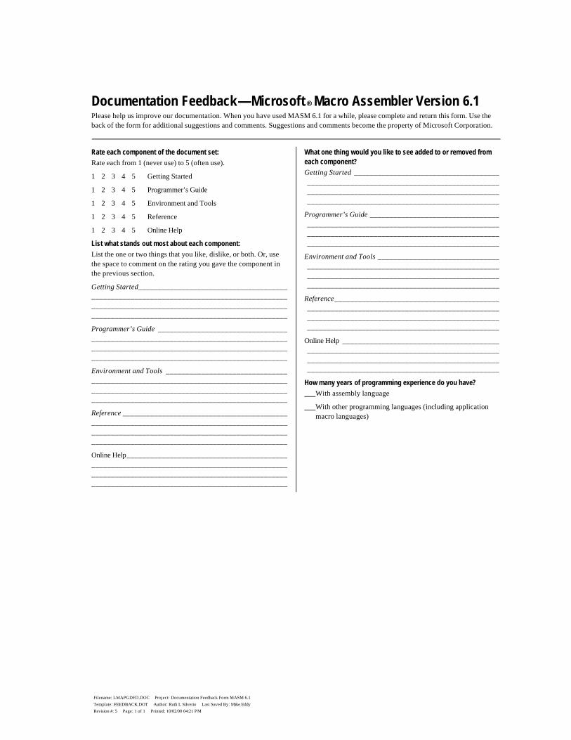
Filename: LMAPGDFD.DOC Project: Documentation Feedback Form MASM 6.1 Template: FEEDBACK.DOT Author: Ruth L Silverio Last Saved By: Mike Eddy Revision #: 5 Page: 1 of 1 Printed: 10/02/00 04:21 PM
Documentation Feedback — Microsoft ® Macro Assembler Version 6.1 Please help us improve our documentation. When you have used MASM 6.1 for a while, please complete and return this form. Use the back of the form for additional suggestions and comments. Suggestions and comments become the property of Microsoft Corporation.
Rate each component of the document set:
Rate each from 1 (never use) to 5 (often use).
1 2 3 4 5 Getting Started
1 2 3 4 5 Programmer’s Guide
1 2 3 4 5 Environment and Tools
1 2 3 4 5 Reference
1 2 3 4 5 Online Help
List what stands out most about each component:
List the one or two things that you like, dislike, or both. Or, use the space to comment on the rating you gave the component in the previous section.
Getting Started______________________________________ __________________________________________________ __________________________________________________ __________________________________________________
Programmer’s Guide _________________________________ __________________________________________________ __________________________________________________ __________________________________________________
Environment and Tools _______________________________ __________________________________________________ __________________________________________________ __________________________________________________
Reference __________________________________________ __________________________________________________ __________________________________________________ __________________________________________________
Online Help_________________________________________ __________________________________________________ __________________________________________________ __________________________________________________
What one thing would you like to see added to or removed from each component?
Getting Started _____________________________________ _________________________________________________ _________________________________________________ _________________________________________________
Programmer’s Guide _________________________________ _________________________________________________ _________________________________________________ _________________________________________________
Environment and Tools _______________________________ _________________________________________________ _________________________________________________ _________________________________________________
Reference__________________________________________ _________________________________________________ _________________________________________________ _________________________________________________
Online Help ________________________________________ _________________________________________________ _________________________________________________ _________________________________________________
How many years of programming experience do you have?
With assembly language
With other programming languages (including application macro languages)
Filename: LMAPGDFD.DOC Project: Documentation Feedback Form MASM 6.1 Template: FEEDBACK.DOT Author: Ruth L Silverio Last Saved By: Mike Eddy Revision #: 5 Page: 2 of 2 Printed: 10/02/00 04:21 PM
Name _____________________________________________
Address ___________________________________________
City/State/Zip _______________________________________
Home Phone ( _____ ) ________________________________
Work Phone ( _____ ) ________________________________
May we contact you for additional information about your comments? Yes No
Additional comments:
......................................................................................................................Fold......................................................................................................................
Place stamp
here.
Post Office
will not deliver
without proper
postage.
Microsoft Corporation Languages — MASM 6.1 One Microsoft Way Redmond WA 98052-9953