Embed Size (px)
Citation preview

III - 1
RATIONALE:
Day by day, engineering and technology experience tremendous growth. Design plays a
major role in developing engineering and technology. Strength of material is backbone for
design. The strength of material deals generally with the behaviour of objects, when they are
subject to actions of forces. Evaluations derived from these basic fields provide the tools for
investigation of mechanical structure.
OBJECTIVES:
x Define various mechanical properties of materials.
x Calculate the deformation of materials, which are subjected to axial load and shear.
x Determine the moment of Inertia of various sections used in industries. x
Estimate the stresses induced in thin shells.
x Draw the Graphical representation of shear force and bending moment of the beam
subjected to different loads.
x Construct SFD and BMD.
x Calculate the power transmitted by the solid & hollow shafts.
x Distinguish different types of spring and their applications.
UNIT I DEFORMATION OF METALS 18 hrs
Mechanical properties of materials: Engineering materials – Ferrous and non ferrous materials -
Definition of mechanical properties such as strength – elasticity, plasticity, ductility, malleability,
stiffness, toughness, brittleness, hardness, wear resistance, machinability, castability and
weldability – Alloying elements- effect of alloying element - Fatigue, fatigue strength, creep –
temperature creep – cyclic loading and repeated loading – endurance limit.
Simple stresses and strains: Definition – Load,stress and strain – Classification of force systems
– tensile, compressive and shear force systems – Behaviour of mild steel in tension up to rupture –
Stress – Strain diagram – limit of proportionality – elastic limit – yield stress – breaking stress –
Ultimate stress – percentage of elongation and percentage reduction in area – Hooke’s law –
Definition – Young’s modulus – working stress, factor of safety, load factor, shear stress and
shear strain – modulus of rigidity. Linear strain – Deformation due to tension and compressive
force– Simple problems in tension, compression and shear force. Definition – Lateral strain –
Poisson’s ratio – Volumetric strain – bulk modulus – volumetric strain of rectangular and circular
bars – problems connecting linear, lateral and volumetric deformation – Elastic constants and their
relationship - Problems on elastic constants - Definition – Composite bar – Problem in composite
bars subjected to tension and compression – Temperature stresses and strains – Simple problems –
Definition – strain energy – proof resilience – modulus of resilience – The expression for strain
energy stored in a bar due to Axial load – Instantaneous stresses due to gradual, sudden, impact
and shock loads – Problems computing instantaneous stress and deformation in gradual, sudden,
impact and shock loadings.
UNIT II GEOMETRICAL PROPERTIES OF SECTIONS AND THIN SHELLS 18 hrs
Properties of sections: Definition – center of gravity and centroid – position of centroids of plane
geometrical figures such as rectangle, triangle, circle and trapezium-problems to determine the
TERM PROGRAMME HOURS /
WEEK
TOTAL
HOURS
III DIPLOMA IN MECHANICAL
ENGINEERING (Tool & Die) 6 96
COURSECODE COURSE NAME MAXIMUM
MARKS
MIN. MARKS
FOR PASS
M7TD204 STRENGTH OF MATERIALS 75 30

III - 2
centroid of angle, channel, T and I sections only - Definition-centroidal axis-Axis of symmetry.
Moment of Inertia – Statement of parallel axis theorem and perpendicular axis theorem. Moment
of Inertia of lamina of rectangle, circle, triangle, I and channel sections-Definition-Polar
moment of Inertia-radius of gyration – Problems computing moment of inertia and radius of
gyration for angle, T, Channel and I sections.
Thin Shells: Definition – Thin and thick cylindrical shell – Failure of thin cylindrical shell
subjected to internal pressure – Derivation of Hoop and longitudinal stress causes in a thin
cylindrical shell subjected to internal pressure – simple problems – change in dimensions of a thin
cylindrical shell subjected to internal pressure – problems – Derivation of tensile stress induced in
a thin spherical shell subjected to internal pressure – simple problems – change in diameter and
volume of a thin spherical shell due to internal pressure – problems.
UNIT III LATERAL DEFORMATION (SF AND BM DIAGRAMS, DEFLECTION OF
BEAMS) 18 hrs
Classification of beams – Definition – shear force and Bending moment – sign conventions for
shear force and bending moment – types of loadings – Relationship between load, force and
bending moment at a section – shear force diagram and bending moment diagram of cantilever and
simply supported beam subjected to point load and uniformly distributed load (udl) –
Determination of Maximum bending moment in cantilever beam and simply supported beam when
they are subjected to point load and uniformly distributed load.
Definition – slope, deflection, stiffness and flexural rigidity – Derivations of relationship between
slope, Deflection and Radius of curvature – Derivation of slope and deflections of cantilever and
simply supported beam by area moment method under point load and udl load– simple problems.
UNIT IV THEORY OF SIMPLE BENDING AND FRICTION 18 hrs
Theory of simple bending – Assumptions – Neutral axis – bending stress distribution –
moment of resistance – bending equation – M/I=f/y=E/R – Definition – section modulus -
rectangular and circular sections – strength of beam – simple problems involving flexural formula
for cantilever and simple supported beam.
Definition – force of friction – limiting friction- static – dynamic friction – angle of friction – co-
efficient of friction – cone of friction – laws of static and dynamic friction – ladder problems
UNIT V TORSION AND SPRINGS 18 hrs
Theory of torsion – Assumptions – torsion equation – strength of solid and hollow shafts – power
transmitted – Definition – Polar modulus – Torsional rigidity – strength and stiffness of shafts –
comparison of hollow and solid shafts in weight and strength considerations – Advantages of
hollow shafts over solid shafts – Problems.
Types of springs – Laminated and coiled springs and applications – Types of coiled springs –
Difference between open and closely coiled helical springs – closely coiled helical spring

III - 3
subjected to an axial load – problems to determine shear stress, deflection, stiffness and resilience
of closed coiled helical springs.
Revision and Test 6Hrs
Text Books: 1) Strength of Materials ,R. S. Khurmi, , S.Chand & Co., Ram Nagar, New Delhi –
2002
2) Strength of Materials, S. Ramamrutham, 15 th Edn 2004, DhanpatRai Pub. Co.,
New Delhi.
Reference Books:
1) Strength of Materials ,R.K. Bansal,, Laxmi Publications Pvt. Ltd., New Delhi, 3rd Edition,
2010.
2) Strength of materials, S.S.Rattan, Tata Mcgraw hill, New Delhi,2008, ISBN 9780070668959,
3) Strength of Materials, B K Sarkar, I Edition, 2003 Tata Mcgraw hill, New Delhi.
4) Engineering mechanics, R.K. Bansal, Laxmi Publications Pvt. Ltd., New Delhi, 2nd Edition,
2007

III - 4
MODEL QUESTION - I
Term : III Time : 3 Hrs.
Program : Diploma in Mechanical Engg (Tool & Die) Max Marks : 75
Course : Strength of Materials. Course code : M7TD204
PART – A Answer any 15 questions 1x15=15
1. Define Ductility
2. State the relationship between E and K
3. State Hooke’s law
4. What is lateral strain
5. State the parallel axis theorem
6. Define Hoop Stress
7. Define Thin cylindrical shell
8. Define Moment of inertia
9. What is radius of curvature
10. Define Slope
11. Define Bending moment
12. State the relationship between BM and SF
13. What is neutral axis
14. Write a formula for bending equation
15. Define section modulus
16. Define centre of curvature
17. What is twisting moment
18. State the application of laminated spring
19. List out the types of springs
20. What is polar moment of inertia?
PART – B Answer all the questions 12x5=60
21. a) i) A steel bar 2m long 20mm wide and 10mm thick is subjected to an axial pull
of 20KN in the direction of its length. Determine the changes in length and
III - 5
volume. Take E = 2 x 10⁵ N/mm2 and 1/m = 0.3 (4)
ii) A brass tube of 50mm outside diameter, 45mm inside diameter and 300mm long is
compressed between end washers with load of 24.5KN. Reduction in length is
0.0015mm. Determine the stress, strain and Young’s modulus. (8)
(or)
b) A weight of 9.8KN is dropped on to a collar at the lower end of a vertical bar 3m long
and 32mm diameter. Calculate the height of drop, if the maximum instantaneous stress
is not to exceed 240N/mm2. What is the corresponding instantaneous elongation?
Assume E = 2 x 10⁵ N/mm2. (12)
22) a) i) Find the centroid of a channel section 100 x 50 x 15 mm (4)
ii) Determine the change in diameter, change in volume of the spherical shell 2m in
diameter and 12mm thick subjected to an internal pressure of 2 N/mm2. Take
E = 2 x 10⁵ N/mm2 and 1/m = 0.25 (8)
(or)
b) A thin cylindrical shell of 1m internal diameter 5mm thick and 2.5m long is filled with
a fluid under pressure until its volume increases by 40 x 106 mm3. Determine the
pressure exerted by the fluid on the shell. Take E = 2x10⁵ N/mm2 and 1/m=0.25 (12)
23) a) A beam is freely supported over a span of 8m. It carries a point load of 3KN at 2m
From left hand support and an udl of 2KN/m from the centre upto the right hand
support. Draw the SFD and BMD. (12)
(or)
b) A cantilever 2m long carries a point load of 20KN at 0.8m from the fixed end and
another point load of 5KN at the free end. In addition, a udl of 15KN/m is spread over
the entire length of the cantilever. Draw SFD and BMD (12)
24 a) i) State the assumptions made in the theory of simple bending. (4)
ii) A wooden beam of rectangular section 100 x 200 mm is simply supported over a
span of 6m. Determine the udl it may carry, if the bending stress is not to exceed
7.5 N/mm2. Estimate the concentrated load it may carry at the centre of the beam
with the same permissible stress. (8)
(or)
b)i) A beam of T-section flange 150mm x 50mm web thickness 50mm, overall depth 200mm
and 10m long is simply supported a central point load of 10KN. Determine the
maximum fibre stresses in the beam. (6)
ii) Derive the flexural formula (6)
III - 6
25. a) A truck weighing 30KN and moving at 5 Km/hr has to be brought to rest by buffer. Find
how many springs, each of 18 coils will be required to the energy of motion during a
compression of 200mm. The spring is made out of 25mm diameter steel rod coiled to a
mean diameter of 240mm. Take N = 0.84 x 10⁵ N/mm2. (12)
(or)
b) i) A solid shaft 20mm diameter transmits 10KW at 1200rpm. Calculate the maximum
intensity of shear stress induced and angle of twist in degrees in a length of 1m, if
modulus of rigidity for the shaft material is 8 x 10⁴ N/mm2 (6)
ii) A closed coiled spring made of steel wire 100mm diameter has 10 coils of 120mm mean
diameter. Calculate the deflection under an axial load of 100N and stiffness of the spring.
TakeC=1.2mPa. (6)
III -6
MODEL QUESTION - II
Term : III Time : 3 Hrs.
Program : Diploma in Mechanical Engg (Tool & Die) Max Marks : 75
Course : Strength of Materials. Course code : M7TD204
PART – A Answer any 15 questions 1x15=15
1. Define toughness.
2. Define Poisson’s Ratio.
3. Define proof resilience.
4. Write any two elastic constant.
5. Define centroid.
6. Write down the unit of moment of Inertia.
7. Define thin cylindrical shell.
8. Define Moment of inertia
9. List out the types of beams.
10. Define sheer force.
11. Define the term deflection.
12. Define radius of curvature.
13. Define the term bending stress.
14. Define Neutral axis.
15. What is limiting friction?
16. Define Static friction.
17. Define pure torsion.
18. Write any two advantages of hollow shafts over solid shafts.
19. Give the applications of tension springs.
20. Define stiffness of spring.
PART – B Answer all the questions 12x5=60
21. a) i) Determine the value of Poisson's Ratio and Young's modulus of Rigidity of the material is
0.5 x 10⁵ N/mm
2 and bulk modulus 0.8x 10
5 N/mm
2 (6)
ii) Draw stress – strain for a mild steel specimen loaded upto failure and explain the
salient features. (6)
(or)
b) i) A copper rod 30mm is surrounded tightly by a cast iron tube of 60mm outside diameter
the ends being firmly fastened together. When put to a compressive load of 12kN.
What load will be shared by each? Also estimate the amount by which the compound
bar shortens in a length of 10mm. Assume ECI = 1.2 x 10⁵ N/mm
2 and Ec = 1x10
5N/mm
2 (8)
ii) Calculate the Strain Energy that can be stored in a steel bar 40mm in diameter and 3m long
subjected to a pull of 100KN. Given E=200KN/mm2 (4)

III -7
22. a .i) State Parallel axis theorem. (4)
ii) An I-Section has the top Flange 120mm x 120mm thick, web 180mm x 20mm thick and
the bottom flange 200mm x 40mm thick. Calculate the Ixx, Iyy, Kxx and Kyy of the
section. (8)
(or)
b) i) What working pressure may be allowed in a boiler shell 1.8m diameters with plates 15mm
thick, if the permissible tensile stress in the solid plate is not to exceed 70 N/mm2 (3)
ii) A Cylindrical Shell 24 m long, 600mm in diameter is made up of 15mm thick plates. Fine
the change in length, diameter and volume of the cylinder when the shell is subjected
to an internal pressure of 2N/mm2. E=2 x 10
5 N/mm
2 1/m=0.3 (9)
22. a) i) A cantilever of span 5m is loaded with three point load of 2KN at 2, 4, 5m from
the fixed end in addition to a UDL of 1KN/m to a length of 4m from the fixed
end. Draw SF and BM diagram. (6)
ii) A simply supported beam of 5m span carries a UDL of 2 KN/m over the entire span. In
addition the beam carries a point load of 4KN at a distance of 2m from the left
support. Draw SFD and BMD. (6)
(or)
b.i) A Cantilever 2m long, 100mm wide and 200mm deep carries a concentrated load of
5KN at the free end. Find the max slope and deflection. E= 2 x 10⁵ N/mm2
(4)
ii) A cantilever beam 6m long is subjected to a UDL of W KN/m speed over the
entire span. Assuming Rectangular section with depth equal to twice the
width determine the size of the beam so that the max deflection does not
exceed 15mm. the max stress should not exceed 100 N/mm2. E=2 x 10⁵ N/mm
2 (8)
23. a) i) Calculate the max stress in a piece of rectangular steel strip 25mm wide and 3mm
thick when it is bend round a drum, 2.5m diameter. E= 2 x 10⁵ N/mm2 (6)
ii) Derive the relationship between the curvature slope and deflection of the beam. (6)
(or)
b) i) Enumerate the laws of static and dynamic friction. (6)
ii) Explain the term friction? What is limiting friction? (6)
25. a) i) State the assumptions made in the derivation of the tension formula. (4)
ii) A solid shaft has to transmit 10 kw at 210rpm. The max. torque transmitted
is each revolution exceeds the mean by 30%. If the Shear stress is not to
exceed 80 N/mm2. Find a suitable diameter of the solid shaft. Calculate the
angle of twist for a length of 2 meters. C=0.8 X10⁵N/mm
2 (8)
(or)
III -8
b) i) Distinguish between C closely coiled helical springs and an open coiled helical
spring. (4)
ii) Design a closely coiled spring of stiffness 20 N/mm deflection. The max.
shear stress in the spring metal is not exceed 80 N/mm2 under a load of 600 N
. The diameter of the coil is to be 10 times the diameter of the wire. Take the
modulus of Rigidity as 85 KN/mm2. (8)
RATIONALE:
To be a Mechanical Engineer, it is necessary to understand the various technologies that are
being used in the process of conversion of raw materials in to finished products. So it is very
essential to learn the basics of various technologies and processes that are available and
predominantly used in industries
OBJECTIVES:
• Acquire Knowledge about casting, molding process and types of pattern,
• Explain hot working and cold working processes
• Appreciate the safety practices used in welding
• Explain Powder Metallurgy Process
• Explain Lathe and its working parts
• Describe the functioning of semi automatic lathes and automatic lathes
• Explain the working of machine tools planer, shaper and slotter
UNIT I CASTING PROCESSES 15 hrs
PATTERNS – definition – pattern materials – factors for selecting pattern materials – single piece solid,
split patterns – pattern allowances – core prints.
MOULDING – definition – moulding boxes, moulding sand – ingredients – silica – clay – moisture and
miscellaneous materials – properties of moulding sand – sand additives – moulding sand
preparation – mixing – tempering and conditioning – types of moulding – green sand – dry sand –
machine moulding – Top and bottom squeezer machines – Jolting machines – sand slinger- core – CO2
process core making – types of core – core boxes.
CASTING – definition – sand casting using green sand and dry sand – gravity die casting – pressure die
casting – hot and cold- chamber processes – centrifugal casting – continuous casting – chilled casting –
TERM PROGRAMME HOURS /
WEEK
TOTAL
HOURS
III DIPLOMA IN MECHANICAL
ENGINEERING (Tool & Die) 5 80
COURSE
CODE COURSE NAME
MAXIMUM
MARKS
MIN. MARKS
FOR PASS
M7TD205 MANUFACTURING TECHNOLOGY 75 30

III -9
malleable casting –melting of cast iron – cupola furnace – melting of non ferrous metals – crucible
furnace melting of steel and arc furnaces – induction furnaces – instrument for measuring temperature –
optical pyrometer – thermo electric pyrometer – cleaning of casting – tumbling, trimming, sand and shot
blasting – defects in casting – causes and remedies – safety practices in foundry.
UNIT II JOINING PROCESSES 15 hrs
Arc Welding : Definition – arc welding equipment – arc welding methods –carbon arc, metal arc, Metal
Inert gas (MIG), Tungsten inert gas (TIG),Atomic hydrogen, Plasma arc, Submerged arc and Electro slag
welding,
Gas welding : Definition Gas Welding Equipment– oxy – acetylene welding
Three types of flame-resistance welding – definition – classification of resistance welding – butt – spot –
seam – projection welding – welding related processes – oxy – acetylene cutting – arc cutting – hard
facing bronze welding - soldering and brazing special welding processes – cast iron welding– thermit
welding – solid slate welding, ultrasonic, diffusion and explosive welding – explosive cladding – modern
welding, electron beam and laser beam welding – types of welded joints– merits and demerits of welded
joints – inspection and testing of welded joints – destructive and non destructive types of tests – magnetic
particle test – radiographic and ultrasonic test defects in welding – causes and remedies –
safety practices in welding.
Unit III BULK FORMATION PROCESSES AND POWDER METTALLURGY 15 hrs
Hot working, cold working – advantages of hot working and coldworking– hot working operations –
rolling – forging, smith forging, drop forging, upset forging, press forging – roll forging.
Methods of manufacturing metal powders – atomization, reduction and electrolysis deposition –
compacting – sintering– sizing – infiltration – mechanical properties of parts made by powder
metallurgy – design rules for the power metallurgy process.
Unit IV CENTRE LATHE AND SPECIAL PURPOSE LATHE 15 hrs
Centre lathe: Theory of lathes – specifications – simple sketches – principal parts – head stock – back
geared type all geared type – tumbler gear mechanism – quick change gear box – apron mechanism –
carriage cross slide – automatic, longitudinal and cross feed mechanism – tail stock and its functions –
work holding device – face plate – three jaw chuck – four jaw chuck – catch plate and carrier – types of
centre.
Machining operations done on lathe straight turning – step turning-taper turning- knurling- Thread
cutting-Facing-Boring-chamfering–-cutting speed-feed-depth of cut.
Semi automatic lathes:
Types of semi automatic lathes – capstan and turret lathes – difference between turret and capstan – tools
and work holding devices – self opening die head – collapsible taps.
Automatic Lathes:
III -10
Automatic lathe – classification of single spindle automatic lathe – principle of automatic lathes –
automatic screw cutting machines – multi spindle automatic lathes.
Unit V RECIPROCATING MACHINES 15 hrs
Planer: Types of planers-description of double housing planer-specifications- principles of operation-
drives-quick return mechanism-feed mechanism- work holding devices and special fixtures-types of tools
- various operation
Shaper: Types of shapes-specifications-standard-plain-universal-principles of operations –drives -quick
return mechanism-crank and slotted link-feed mechanism- work holding devices - Special
fixture-various operations.
Slotter: Types of slotters-specifications-method of operation-Whitworth quick return mechanism - feed
mechanism-work holding devices-types of tools.
Revision and Test 5Hrs
Text Books:
1. Hajra Chowdry & Bhattacharaya, Elements of workshop Technology Volume I & II, Edn. XI,
Media Promoters & Publishers Pvt. Ltd., Seewai Building `B’, 20-G, Noshir Bharucha Marg,
Mumbai 400 007 – 2007.
2. R. S. Khurmi & J. K. Gupta, A Text book of workshop Technology, Edn. 2, S.Chand & Co.,
Ram Nagar, New Delhi - 2002.
Reference Books:
1. Begeman, Manufacturing process, Edn. 5, McGraw Hill, New Delhi 1981.
2. WAJ Chapman, Workshop Technology, Volume I, II, & III, Vima Books Pvt. Ltd., 4262/3,
Ansari Road, Daryaganj, New Delhi 110 002.
3. Raghuwanshi, Workshop Technology, Khanna Publishers.Jain & Gupta, Production
Technology, Edn. XII, Khanna Publishers,
2-B, North Market, NAI Sarak, New Delhi 110 006 - 2006
4. P. C. SHARMA, Production Technology, Edn. X, S.Chand & Co. Ltd., Ram Nagar,
New Delhi 110 055 – 2006
5. HMT, Production Technology, Edn. 18, published by Tata McGraw Hill publishing
Co Ltd, 7, West Patel Nagar, New Delhi 110 008. – 2001.
6. Kalpakjian, Manufacturing Engineering & Technology

III -11
MODEL QUESTION - I
Term : III Time : 3 Hrs
Programme : Diploma in Mechanical Engineering (Tool & Die) Max. Marks : 75
Course : Manufacturing Technology Course Code : M7TD 205
PART – A Answer any 15 questions 1x15=15
1. What is casting?
2. What is pattern?
3. What is core?
4. What are the pattern allowances?
5. Name the three types of flames used in Gas welding?
6. Define Welding?
7. Name any two welding defects?
8. List the equipments used in arc welding?
9. Define Forging?
10. What is rolling?
11. What is hot working?

III -12
12. Define powder metallurgy?
13. What are the functions of the lead screws?
14. What are the functions of back gear mechanism?
15. State the application of face plate?
16. List out any two lathe tools?
17. What are the different types of planer?
18. What is planer?
19. What is slotter?
20. What is the function of a clapper box in a shaper?
PART– B
Answer all the questions 5x12=60
21. a) (i) List out the Pattern allowances and explain. (6)
(ii)Explain with neat sketch Co2 Process of core making. (6)
(OR)
b) Sketch and explain the working of an electric arc furnace. ( 12 )
22. a) Explain MIG and TIG welding processes in detail (12 )
(OR)
b) (i)Describe any two types of non destructive test on welded joints (6)
(ii)Describe the process of laser beam welding with the aid of neat sketch. List out its
applications. (6)
23. a) What are the different methods of manufacturing powders in powder metallurgy
process? Explain any two methods ( 12 )
(OR)
b) (i) Explain with sketch the drop forging process (6 )
(ii)List out the mechanical properties of parts made by powder metallurgy. (6)
24. a) Explain with a neat sketch a single spindle automatic lathe. ( 12 )
(OR)
b) (i) List out the work holding devices used in a lathe. Explain with a neat sketch any one work
holding device. (8)
(ii)Give differences between capstan and turret lathe. (4)
25. a) (i)Explain how the stroke adjustment is made in a shaper. (4)
(ii)Describe with neat sketch the principle parts of a slotter (8)
(OR)
b) Explain the construction and working of a double housing planner with a neat sketch. (12)
III -13
MODEL QUESTION - II
Term : III Time : 3 Hrs
Programme : Diploma in Mechanical Engineering (Tool & Die) Max. Marks : 75
Course : Manufacturing Technology Course Code : M7TD 205
PART – A Answer any 15 questions 1x15=15

III -14
1. What is pattern allowance?
2. When core is used in a moulding?
3. Name the types of cores.
4. What is the use of optical pyrometer?
5. Name the various arc welding methods.
6. What inert gas is used in TIG welding?
7. What is soldering?
8. What is the use of explosive cladding?
9. What is atomization?
10. What is smith forging?
11. What is the main advantage of hot working over cold working?
12. What is drop forging?
13. What is the use of tail stock?
14. Define cutting speed.
15. Name the methods by which taper can be produced in a lathe.
16. What is the use of face plate?
17. Name the types of planners.
18. What is the advantage of quick return motion mechanism?
19. How angular surfaces are machined in a shaper?
20. What type of work holding device is used for clamping thin plates on a shaper?
PART– B
Answer all the questions 5x12=60
21. A) (i) Explain the various factors affecting selection of pattern materials. (6)
(ii) Explain the various ingredients of moulding sand. (6)
(OR)
B) (i) Sketch and explain in detail the Hot and Cold chamber die casting processes. (12)
22. A) (i) Explain the Tungsten Inert Gas welding Process. (6)
(ii) Explain the advantages of Submerged arc welding process. (6)
(OR)
B) (i) Sketch and explain the various resistance welding processes.( 12 marks)
23. A) (i) Explain the Roll forging and upset forging processes . (6)
(ii) Explain mechanical properties of parts made of powder metallurgy process. (6)
(OR)
B) (i) Sketch and explain in the various methods of manufacturing metal powders (12)
24. A) (i) Explain the working principle of automatic lathe. (6)
(ii) Explain how a lathe is specified. (6)

III -15
(OR)
B) (i) Sketch and explain tumbler gear mechanism in a lathe machine. (12)
25. A) (i) Explain the quick return mechanism used in a planner. (6)
(ii) Explain the various types of tools used in a slotter. (6)
(OR)
B) (i) Sketch and explain the crank and slotted link mechanism used in shaper. (12)

III - 15
TERM PROGRAMME HOURS / WEEK TOTAL HOURS
III DIPLOMA IN MECHANICAL ENGINEERING
(Tool & Die) 5 80
COURSE
CODE COURSE NAME
MAXIMUM
MARKS
MIN. MARKS
FOR PASS
M7TD 301 Engineering Metrology 75 30
Rationale:
The modern industries demand wide knowledge in the understanding and use of conventional
and advanced digital measuring instruments that are being used in the process of manufacture of goods.
Hence it is essential to have better understanding of the various measuring techniques and the technology
that are being used in the various measuring instruments. The fundamentals of various measuring
technique needs to be known to understand the modern measuring equipments that are being used in
Industries.
OBJECTIVES:
• To the Understand the Needs & Objectives of metrology.
• To Understand about the various linear & angular measuring
Instruments
• To Study about the various Measurement Techniques.
• To Calibrate an Instrument.
• To Know about various geometric parameters.
• To use Light rays in Measuring an Object.
• To Measure Force, Torque and temperature
• To know about the measuring machines.
• To acquire Knowledge about Recent Trends in Metrology.
UNIT I INTRODUCTION TO METROLOGY AND LINEAR MEASUREMENT 15 hrs
1.1 Introduction:
Metrology, objectives of metrology, precision vs accuracy. Repeatability, calibration,sensitivity and
readability, classification of methods of measurement, general care of equipments.
1.2 Non precision Linear Measurements:
Surface plates, Tool maker’s flats and high precision surface plates, Angle plates, bench centers, v-
blocks, straight edges, Toolmaker’s straight edges, using a straight edge, sprit levels, combination set,
universal surface gauge, Engineer’s square, Engineer’s parallel, Radius gauge, feeler gauge, screw pitch
gauge, Engineer’s taper, wire and thickness gauge.
1.3 Precision Linear Measurements: -
Characteristics and principles of precision measuring instruments. Vernier instruments,types of vernier
calipers, errors in calipers, Vernier height gauge, Vernier depth gauge, digital readout height
gauge.Micrometers – Internal micrometers, micrometer depth gauge, thread micrometer, v-anvil
micrometer, dial micrometers,
digital micrometers, groove micrometer. Telescope internal gauge, Measuring dia of deep holes,

III - 16
cylinder gauges, Keilpart gauge, slip gauges.
UNIT II ANGULAR MEASUREMENT, MEASUREMENT OF GEARS AND THREADS 15 hrs
2.1 Angular Measurement: - Instruments for angular measurement – Vernier and optical bevel
protractor, universal bevel protractor, acute angle attachment, optical dividing head, Sine bars, Sine
center, angle gauges, clinometers.
2.2 Optical instruments for angular measurement: - Autocollimator – principle of the autocollimator,
micro optic autocollimator, applications of autocollimator. Angle dekkor – working principle, use of
angle dekkor in combination with angle gauges.Optical square.
2.3 Measurement of Gears:
Gear tooth terminology, Gear tooth calliper, Composite method of Gear checking, Parkinson’s Gear
tester, Master Gear.
2.4 Thread Measurements: Screw thread projection – Tool Maker’s Microscope – Measurement of
Effective Diameter – One wire, Two wire and Three wire Methods.
UNIT III MEASUREMENT OF GEOMETRIC PARAMETERS AND SURFACE FINISH 15 hrs
3.1 Straightness, Flatness, Parallelism and squareness: - Definition of straightness, straight edge and
its use, test for straightness by using spirit level and Autocollimator, Flatness definition, flatness testing,
procedure for determining flatness, laser equipment for alignment testing. Parallelism definition,
various cases of parallelism of lines and planes, measurement of equidistance, checking of coincidence or
alignment. Squareness definition, measurement of squareness of lines and planes, checking the
perpendicularity of motion, squareness testing methods – indicator method, Engineer’s square tester,
optical tests for squareness.
3.2 Circularity and Rotation: -
Circularity definition, measurement of circularity, Different types of irregularities of a circular part –
ovality, lobbing, irregularities of non specific form. Roundness and circularity. Devices for measuring
circularity error– V block, precision measuring instruments. Tests for checking Rotation – Run out,
measurement of run out, Periodical axial slip, camming.
3.3 Surface Finish : -
Surface roughness – definition, terminologies as per BIS, Methods of measuring Surface finish –
Surface inspection by comparison methods, Direct measurement methods. Analysis of surface traces.
UNIT IV COMPARATORS AND MEASUREMENT BY LIGHT WAVE INTERFERENCE 15 hrs
4.1 Comparators: Characteristics and uses of comparators, Working principle, advantages and
disadvantages of various types of comparators– Mechanical comparators, optical comparators, Electrical
comparators, pneumatic comparators, Fluid displacement comparators, optical Projectors.
4.2 Measurement by light wave interference: Interferometry, interference of two rays, light source for
interferometry, interferometry applied to flatness testing, Interferometers.
4.3 Testing and Calibration of Gauges: - Calibration of linear and angular measuring instruments –
General metrological instrument, optical measuring instruments, Measurement of limit gauges.
UNIT V MEASURING MACHINES, FORCE, TORQUE, POWER & TEMPERATURE
MEASUREMENT & RECENT TRENDS IN METROLOGY 15 hrs
5.1 Measuring Machines: Optical profile projector – working principle, use, precaution in use.
Coordinate Measuring Machine – Types, uses, advantages, possible source of error in CMM.
Electronic Inspection and measuring machines.

III - 17
5.2 Force, Torque, Power & Temperature Measurement:
5.2.1 Force Measurement: Introduction, Force balance, hydraulic load cell, pneumatic load cell,
Elastic force devices, Separation of Forces – calibration.
5.2.2 Torque & Power Measurement: Definition, Transmission, Dynamometer, Driving type
Dynamometer, Absorption Dynamometer.
5.2.3 Temperature Measurement: Introduction, Non Electrical methods, Electrical methods, Radiation
methods.
5.3 Trends in Metrology: Laser Telemetric system, Feeler microscope, Isometric viewing of surface
defects. Optoelectronic dimensional gauging, computers in metrology, Computer Aided dimensional
analysis and reporting system, In process probing, contact less 3D measurements by Laser based system.
Revision and Test 5Hrs
Text books
1. R.K.Jain., Engineering Metrology, Khanna Publishers, Eleventh edition,1989.
2. R.Jenkins, Fundamentals of Mechanical Inspection, McGraw Hill Book company
III Reference books :
1. ASTME, Hand book of Industrial Metrology, Prentice Hall
2. A.J.T Scarr, Metrology and Precision Engineering, McGraw Hill Book company.
3. J.Johnson, Precision Measurement, Pitman publishers
4. R.L.Murty, Precision Engineering in Manufacturing, New Age International Publishers (P)
limited,1995.
5. A.W.Judge, Engineering Precision Measurements, Chapman and Hall Publishers.
6. A.P.Miller, Engineering Dimensional Metrology, Arnold publishers.
7. W.Mollard, Essentials of Precision Inspection, McGraw Hill Book company.F.H.Rolt,
Gauges and Fine Measurements, Macmillan book company.
8. P.C.Nakra & K.K.Chowdhry, Instruments, Measurements & Analysis

III - 18
MODEL QUESTION - I
Term : III Time : 3 Hrs
Programme : Diploma in Mechanical Engineering (Tool & Die) Max. Marks : 75
Course : Engineering Metrology Course Code : M7TD301
PART – A Answer any 15 questions 1x15=15
1. Define Metrology
2. Define Accuracy
3. What are the uses of straight edges?
4. What are the types of micrometers?
5. Mention any five angular measuring instruments.
6. What is the use of acute angle attachment?
7. Mention any five types of optical instrument for angular measurement.
8. Define module of the gear.
9. Define straightness.
10. Define Parallelism.
11. What is meant by run out?
12. Define waviness.
13. Mention the types of comparator.
14. What is interferometry?
15. What are the light sources used for interferometry?
16. Define Calibration.
17. What is CMM?
18. What are the uses of optical profile projector?
19. What are the instrument used for measuring force?
20. What are the uses of CMM?
PART- B
Answer all Question 5X12=60
21. a) (i) Differentiate precision and accuracy. ( 6 )
(ii) Explain combination set with neat sketch. ( 6 )
(OR)
b). Sketch and explain Vernier depth gauge. (12)
22. a) Explain measurement of angle by using Sine Bar with neat sketches. (12)
(OR)
b) (i) Explain Angle Dekkor with sketches. ( 4 )
(ii) Explain Gear tooth Vernier Caliper with neat sketches. ( 8 )
23. a) (i) Explain Engineer square tester with a neat sketch. (6)
(ii) Explain the procedure for checking periodical axial slip and camming. (6)
(OR)
b) Explain direct measurement methods for determining surface finish. (12)

III - 19
24. a) Explain fluid displacement comparator with neat sketches. (12)
(OR)
b) (i) Explain Testing of flatness by interferometry. (8)
(ii)Write the calibration procedure for linear measuring instruments. (4)
25. a) Sketch and explain Optical Profile projector. (12)
(OR)
b) (i) Explain the working principle of absorption type dynamometer. (8)
(ii)Write short notes on computers in metrology (4).
III - 20
MODEL QUESTION - II
Term : III Time : 3 Hrs
Programme : Diploma in Mechanical Engineering (Tool & Die) Max. Marks : 75
Course : Engineering Metrology Course Code : M7TD301
PART – A Answer any 15 questions 1x15=15
1. Write the least count of vernier caliper
2. Define precision
3. List out the uses of internal micrometer
4. Write down the advantages of combination set.
5. Write down the formula for determine the angle by using sine bar
6. What is the principle used in autocollimator
7. What is the use of optical square?
8. Write down the applications for universal bevel protector
9. Define surface roughness
10. What is the use of straight edge??
11. Define coincidence
12. List out the different types of irregularities of a circular part?
13. Write down the working principle of mechanical comparator
14. What are the uses of fluid displacement comparator?
15. Write down the importance of calibration
16. How can flatness tested by using interferometry?
17. What is Feeler microscope?
18. Define force balance
19. Write down the working principle of optical profile projector
20. List out the types available for measuring temperature.
PART- B
Answer all Question 5X12=60
21. a) (i) Explain about repeatability and readability (4)
(ii) Briefly explain with the use of neat sketch: micrometer (8)
(OR)
(b) (i) Classify the methods of measurements and give two examples for each (4)
(ii) Sketch and explain: screw pitch gauge (8)
22. (a) List out the methods of angular measurement and briefly explain any two methods (12)
(OR)
(b) List out the methods of measuring threads and briefly explain any two wire methods. (12)
23. (a) Define straightness, write down its types. Briefly explain about any one type (12)
(OR)
(b) (i) Define circularity and explain the tests for checking rotation (6)
(ii) Define parallelism and explain various casus of parallelism of lines and planes (6)

III - 21
24 (a) What are uses of comparator and explain any one type with neat sketch (12)
(OR)
(b) (i) Briefly explain about optical measuring instruments (8)
(ii) Write down the calibration procedure for angular measuring instruments (4)
25. a) Sketch and explain CMM and its merits, application (12)
(OR)
b) Briefly explain about contactless 3D measurement by laser based system (12)

III - 22
RATIONALE:
Manufacturing of various machine parts and production of various equipments in small scale to big scale
industries start from the basic drawing of components. The assembly of components is also carried out
from the drawing. So drawing is an important subject to be studied by supervisor cadre students to carry
and complete the production and assembly process successfully.
The first three are theory units in which the students can comprehend the various types of sections used
in drawing practice. Types of fits used, limits and tolerances of dimensions and surface finish methods
which are to be used in industrial drawing will also be taught in these three units.
The fourth unit is also a theory unit in which the students can understand the types of fasteners and study
of temporary fasteners like keys, screw threads and threaded fasteners which are commonly used in
assembly process.
The final unit gives the practice of manual drawing of the commonly used components in industries to
give a thorough knowledge of drawings.
The overall objective is to impart knowledge to the students so as to carry out the production and the
assembly process without wastage of Man/Machine and Materials to have economical overall process.
OBJECTIVES:
• Appreciate the need for sectional view and types of sections.
• Draw sectional views using different types of sections.
• Explain the use of threaded fasteners and the types of threads.
• Compare hole basis system with shaft basis system.
• Select different types of fits and tolerance for various types of mating parts.
• Appreciate the importance of fits and tolerance.
UNIT I SECTIONAL VIEWS 3 hrs
Review of sectioning – Conventions showing the section – symbolic representation of cutting
plane- types of section – full section, half section, offset section, revolved section, broken
section, removed section – section lining.
UNIT II LIMITS, FITS AND TOLERANCES 6 hrs
Tolerances – Allowances – Unilateral and Bilateral tolerances. Limits –Methods of
tolerances Indication of tolerances on linear dimension of drawings – Geometrical tolerances
– application Fits – Classifications of fits – Selection of fits – examples
TERM PROGRAMME HOURS /
WEEK
TOTAL
HOURS
III DIPLOMA IN MECHANICAL
ENGINEERING (Tool & Die) 5 80
COURSECODE COURSE NAME MAXIMUM
MARKS
MIN. MARKS
FOR PASS
M7TD 206 MACHINE DRAWING 75 30

III - 23
UNIT III SURFACE TEXTURE 3 hrs
Surface texture – importance – controlled and uncontrolled surfaces – Roughness – Waviness
– lay – Machining symbols
UNIT IV KEYS, SCREW THREADS AND THREADED FASTENERS 6 hrs
Types of fasteners – temporary fasteners – keys – classification of keys – Heavy duty keys –
light duty keys. Screw thread – Nomenclature – different types of thread profiles – threads
in sections – threaded fasteners – bolts – nuts – through bolt – tap bolt, stud bolt – set
screw –
cap screws – machine screws – foundation bolts
UNIT V MANUAL DRAWING PRACTICE 59 hrs
Detailed drawings of following machine parts are given to students to assemble and draw the
sectional or plain elevations / plans / and side views with dimensioning and bill of materials
1. Sleeve and cotter joint
2. Spigot and cotter joint
3. Knuckle joint
4. Stuffing box
5. Screw Jack
6. Foot step Bearing
7. Universal coupling
8. Plummer block
9. Swivel bearing
10. Simple Eccentric
11. Machine vice
12. Protected type Flanged coupling
13. Connecting rod
14. Tail stock
Revision and Test 3 hrs
Reference Books:
1. Machine Drawing, P.S. Gill, Katsan Publishing House, Ludiana
2. A Text book of Engineering Drawing, R.B. Gupta, Satya Prakasan, Technical
India Publications, NewDelhi
3. Mechanical Draughtsmanship, G.L. Tamta, Dhanpat Rai & Sons, Delhi
4. Geometrical and Machine Drawing, N.D. Bhatt, Cheroter book stalls, Anand,
West Railway
5. Engineering Drawing, D.N. Ghose, Dhanpat Rai & Sons, Delhi

III - 24
MODEL QUESTION PAPER -I
Term : III Time : 3 Hrs
Programme : Diploma in Mechanical Engineering (Tool & Die) Max. Marks : 75
Course : Machine Drawing Course Code : M7TD206
PART A
4 x 5=20
Theory questions:
Answer any four questions
1. Name different types of section. Explain with example full section and half section.
2. Define Hole basis and shaft basis system. Explain with sketch.
3. Name different types of fits. Draw the tolerance zone for defining those fits.
4. Indicate roughness grade symbol for N10.
5. Illustrate the types of keys. Draw a gib headed key with its proportions.
PART B : 55 Marks
1. Assemble and Draw the following views of Sleeve & Cotter Joint (Detailed drawing given)
Full sectional elevation : 30
Plan : 20
Bill of material : 5
III - 25
MODEL QUESTION PAPER -II
Term : III Time : 3 Hrs
Programme : Diploma in Mechanical Engineering (Tool & Die) Max. Marks : 75
Course : Machine Drawing Course code : M7TD206
PART A ( 4 x 5=20)
Theory questions:
Answer any four questions
1. What is the need for sectioning? Explain broken section and revolved section with
neat sketch.
2. Why hole basis system is preferred over shaft basis system? Explain with suitable eg
& sketch.
3. Define i) Lay ii) Waviness with suitable sketch. Draw conventional symbol for
mentioning surface finish.
4. State the conventions followed in representing threads in drawings. Draw the
representation for internal and external threads.
5. Draw 3 views of square nut of diameter 60 mm with proper formulae.
PART– B ( 55)
marks
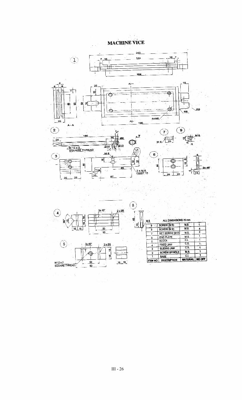
II Assemble and draw the below mentioned views of MACHINE VICE
Right Half sectional elevation : 30
Plan : 20
Bill of material : 05
III - 26

III - 27
OBJECTIVES:
• To practice linear and angular measurements
• To Use vernier caliper, vernier height gauge and micrometer
• To Use slip gauges to make standard dimensions
• To Measure angle of surface using sine bar
• To Use dial indicator to measure geometrical parameters
• To Demonstrate parallelism, squareness and circularity
• To Check the perpendicularity and square ness of a surface
• To Calibrate vernier caliper and micrometer using slip gauges.
I. LINEAR MEASUREMENT:
1 (a) Vernier caliper – Measuring the overall dimensions of a Die plate to an accuracy of 0.02 mm
1 (b) Micrometer – Measuring diameter and thickness of die components to an accuracy of one
micron (0.001mm)
2(i). Vernier height gauge:- a) Measurement of height of the given work piece b) Marking the given
dimensions on the work piece c) Transferring measurements from one job to another.
2(ii). Vernier Depth gauge – Measuring the depth of blind holes in the give work piece.
3(a). Screw thread micrometer – Measuring the root dia of the given screw thread
3(b). Measurement of pitch of screw threads using screw pitch gauges.
4. Measurement of Internal dia of the given die set bush using Inside Micrometer to an accuracy of one
micron.
5. Slip Gauges – Building up the given required dimensions and measuring or marking or setting Go and
No Go sizes in adjustable gap gauges, to an accuracy of 0.5 micron.
6. Measuring the chordal thickness of the gear teeth using the gear tooth vernier.
II ANGULAR MEASUREMENT:
7. Measurement of angles using universal bevel protractor to an accuracy of 5’.
8. Using combination set i) Measure angle in the given component with protractor head
ii) Find or mark the center of the given cylindrical job using center head.
iii) Check and report the square ness of the given specimen using square head.
9. Measure the angle of the surface using Sine bar and Slip Gauges.
III MEASUREMENT OF GEOMETRIC PARAMETERS AND CALIBRATION OF
INSTRUMENTS
10. Straightness – Measurement of concavity/ convexity in a surface using Toolmaker’s straight
edge and feeler gauge.
TERM PROGRAMME HOURS /
WEEK
TOTAL
HOURS
III DIPLOMA IN MECHANICAL
ENGINEERING (Tool & Die) 4 64
COURSE
CODE COURSE NAME
MAXIMUM
MARKS
MIN. MARKS
FOR PASS
M7TD302 Engineering Metrology Practical 75 35

III - 28
11. Checking the parallelism of two planes using dial indicator.
12. Testing circularity of die set pillars using v-block and dial indicators.
13. Measurement of Run-out on i) External cylindrical surface
ii) external conical surface using dial gauge
iii) Checking of Perpendicularity of drill head guide
iv) Checking of squareness of clamping surface of table to its axis.
14. Measurement of axial slip using dial indicators.
15. Calibration and adjusting of micrometers/ Vernier caliper using slip gauges.
SCHEME OF EXAMINATION:
1) PART -A Duration Max Marks
a) Linear Measurement
(OR) 1½ Hrs 35
b) Angular Measurement
2) PART -B
c) Measurement of Geometrical
Parameters & calibration 1½ Hrs 35
Viva – Voce 05
Total 75
SCHEME OF VALUATION:
Observation/Reading -10 marks
Tabulation/ Formula -10 marks
Calculation & Result -15 marks
Part A + Part B - 70 Marks
Viva – Voce - 05 Marks
Total - 75 Marks
Reference Book:
1. R.K.Jain., Engineering Metrology, Khanna Publishers, Eleventh edition,1989.

III - 29
MODEL QUESTION
Term : III Time : 3 Hrs
Programme : Diploma in Mechanical Engineering (Tool & Die) Max. Marks : 75
Course : Engineering Metrology Practical Course Code : M7TD302
PART-A (35 MARKS)
(Linear Measurement and Angular Measurement)
1. Measure the overall dimensions of a given Die plate to an accuracy of 0.02mm by
using the Vernier caliper.
PART – B (35 MARKS)
(Measurement of Geometric Parameters and Machine Tool Metrology)
1. Check the perpendicularity of drill head guide with table in a radial drilling machine.
VIVA VOCE (5 MARKS)
III - 30
OBJECTIVES:
• Identify the parts of a center lathe
• Identify the work holding devices
• Set the tools for various operations
• Operate the lathe and Machine a component
using lathe
• Identify the tools used in foundry.
• Identify the tools and equipments used in
welding
• Prepare sand moulds for different
patterns.
• Perform welding operation to make different types
of joints.
• Identify the different welding defects.
• Appreciate the safety practices used in welding
DETAILED SYLLABUS
1. Lathe
1. Introduction of safety in operation machines.
2. Introduction to lathe and its parts.
3. Introduction to work holding devices and tool holding devices.
4. Types of tools used in lathe work
5. Types of measuring instruments and their uses.
6. Setting of work and tools.
7. Operation of lathe
8. Practice on a lathe
Exercises:
1. Plain turning
2. Step turning
3. Taper turning
4. Thread cutting and knurling
5. Bushing
Lathe Works Time: 4Hrs/
Week
TERM PROGRAMME HOURS /
WEEK
TOTAL
HOURS
III DIPLOMA IN MECHANICAL
ENGINEERING (Tool & Die) 6 96
COURSE
CODE COURSE NAME
MAXIMUM
MARKS
MIN. MARKS
FOR PASS
M7TD207 Manufacturing Technology practical
75 35

III - 31
Manufacture and estimate the cost of the following exercises by assuming the suitable raw material for
the final size of the components.
Note to the faculty :- Last job of the raw material(MS Rod 32x77mm and MS Rod 25x77mm ) to be
retained in student wise or batch wise (Maximum Two Students per batch).This may be verifiable at the
time of Board Practical Examination by the external examiner.
Exercise No:1 – Plain turning.
Raw Material: MS Rod Dia 32 x 77 mm
Exercise No:2-Step turning
Raw Material: Exercise No:1
Exercise No:3-Step and taper turning
Raw Material: Exercise No:2
Exercise No: 4-Step and taper turning
Raw Material: Exercise No: 3

III - 32
Exercise No: 5 Knurling and step turning
Raw Material: Exercise No: 4
Exercise No:6 BSW Thread cutting
Raw Material: Exercise No:5
Exercise No:7 – Metric thread cutting
Raw Material: Exercise No:6
Exercise No:8- Metric thread cutting
Raw Material: Exercise No:7
Exercise No: 9-Shaft and bush mating
Raw Material: MS Rod Dia 25x77mm and Dia 32x30 mm

III - 33
Exercise No: 10-Thread cutting
Raw Material: Exercise No:9
Exercise No: 11-Thread cutting
Raw Material: Exercise No:10
M20(LH)(OR)3/4’’BSW
Exercise No: 12-Eccentric Turning
Raw Material: Exercise No:11
2. Foundry
Syllabus
1. Introduction of tools and equipments
2. Types of patterns
3. Types of sand
4. Preparation of sand moulds
5. Furnaces – crucible furnace and tilting furnace
6. Melting if non ferrous metal
7. Core sands, preparation of cores
Exercises:
Preparation of sand mould:
1. Solid pattern
a. Stepped pulley
b. Bearing top
c. Gear Wheel
d. T-pipe

III - 34
2. Split pattern
a. Bent Pipe
b. Tumbles
3. Loose Piece Pattern – Dove tail
4. Cylindrical core making
5. Melting and casting – (not for Examination, only for class exercises)
6. 3. Welding
Syllabus
1. Introduction of Safety in welding shop
2. Introduction to hand tools and equipments
3. Arc and gas welding equipments
4. Types of joint
Exercises:
1. Arc welding
� Lap joint (Material : 25 mm x 3mm Ms flat)
� Butt joint (Material : 25mm x 6mm Ms flat)
� T- joint (Material : 25mm x 3mm Ms flat)
� Corner joint (Material : 25mm x 3mm Ms flat
2. Gas Welding
� Lap joint (Material : 25mm x 3mm Ms flat)
� Butt joint (Material : 25mm x 6mm Ms flat)
3. Gas cutting : Profile cutting
4. Spot welding – Lap joint (18/20swg)
5. Demonstration of Soldering and brazing
Scheme of Examination
Lathe 45 marks (2hours)
Foundry (or) Welding - by lot 25 marks (1 hour)
Viva-voce 05 marks
Total 75 marks
III - 35
MODEL QUESTION
Term : III Time : 3 Hrs
Programme : Diploma in Mechanical Engineering (Tool & Die) Max. Marks : 75
Course : Manufacturing Technology Practical Course Code : M7TD207
PART A- LATHE (45 marks)
• To make a Step turning as per the dimensions given below.
PART B- FOUNDRY (or) WELDING (25 marks)
• Prepare a mould for a given Stepped pulley pattern.
VIVA-VOCE (5 marks)
TOTAL (75 marks)

III - 36
RATIONALE:
The application of Computer knowledge is essential to the students of all disciplines of
Engineering in addition to their respective branch of study. The Computer Application Practical
course facilitates the necessary knowledge and skills regarding creating, working and maintaining
the documents, analyzing the data with charts manipulation of databases and presentation of
documents with audio visual effects in a computer. The learning of internet provides students
with unprecedented opportunities to obtain information engage in discussion and liaise with
individuals, organizations and groups world-wide. It provides test tools and technologies in
helping the students to fetch better employment.
OBJECTIVES:
On completion of the following exercises, the students must be able to
• Understand the Windows operating systems
• Familiarize and customize the desktop
• Use the different facilities available in the word
processor
• Analyze the data sheet
• Create and manipulate the database
• Prepare PowerPoint presentation
• Understand Internet concepts and usage of e-mail
GUIDELINES:
x All the eighteen experiments given in the list of experiments should be completed
and all the experiments should included for the end semester practical
examination.
x The end semester practical examination question paper contains two
questions-the first question from section-I and the second question from
section-II. Each question carries 35 marks and viva voce carries 5 marks.
x The computer systems should be 1:2 ratio for practical classes
End Examinations – 75 Marks
Content Max. Marks
Section I Section II
Writing steps 15 15
Execution of exercise 15 15
Result with Printout 5 5
Viva voce 5
Total 75 Marks
TERM PROGRAMME HOURS /
WEEK
TOTAL
HOURS
III DIPLOMA IN MECHANICAL
ENGINEERING (Tool & Die) 4 64
COURSE
CODE COURSE NAME
MAXIMUM
MARKS
MIN. MARKS
FOR PASS
M7TD208 Computer Applications practical 75 35
III - 37
LAB EXERCISES:
SECTION – I
WINDOWS
Introduction- History of Windows- screen saver and monitor resolution – Wallpaper setting-Folder
manipulation – properties of a folder – Recycle bin – Short cuts – Sorting Folder – Switching
between Application – Copying in CD/DVD settings – Recording Audio files.
Exercises
1. a. Installing screen saver and change the monitor resolution by
1280X960
b. Setting wall papers
c. Creating, moving, deleting and renaming a folder
d. Copy, paste and cut a folder/file
e. Displaying the properties for a file or folder
2. a. Restoring files and folders from Recycle bin
b. Creating short cuts for folder/file
c. Finding a file or folder by name
d. Selecting and moving two or more files/folders using mouse
e. Sorting folders/files.
3. a. Copying files into CD/DVD
b. Switching between applications
c. Making the taskbar wider and hiding the taskbar
d. Recording and saving an audio file
e. Set/Change the date and time.
WORD PROCESSING
Introduction – Menus – Tool bar – Create – Edit – Save – Alignment – Font Size – Formatting
– Tables – Fill Colors – Mail Merge – Page Setup - Preview – Water marking – Header – Footer
– Clip art.
Exercises
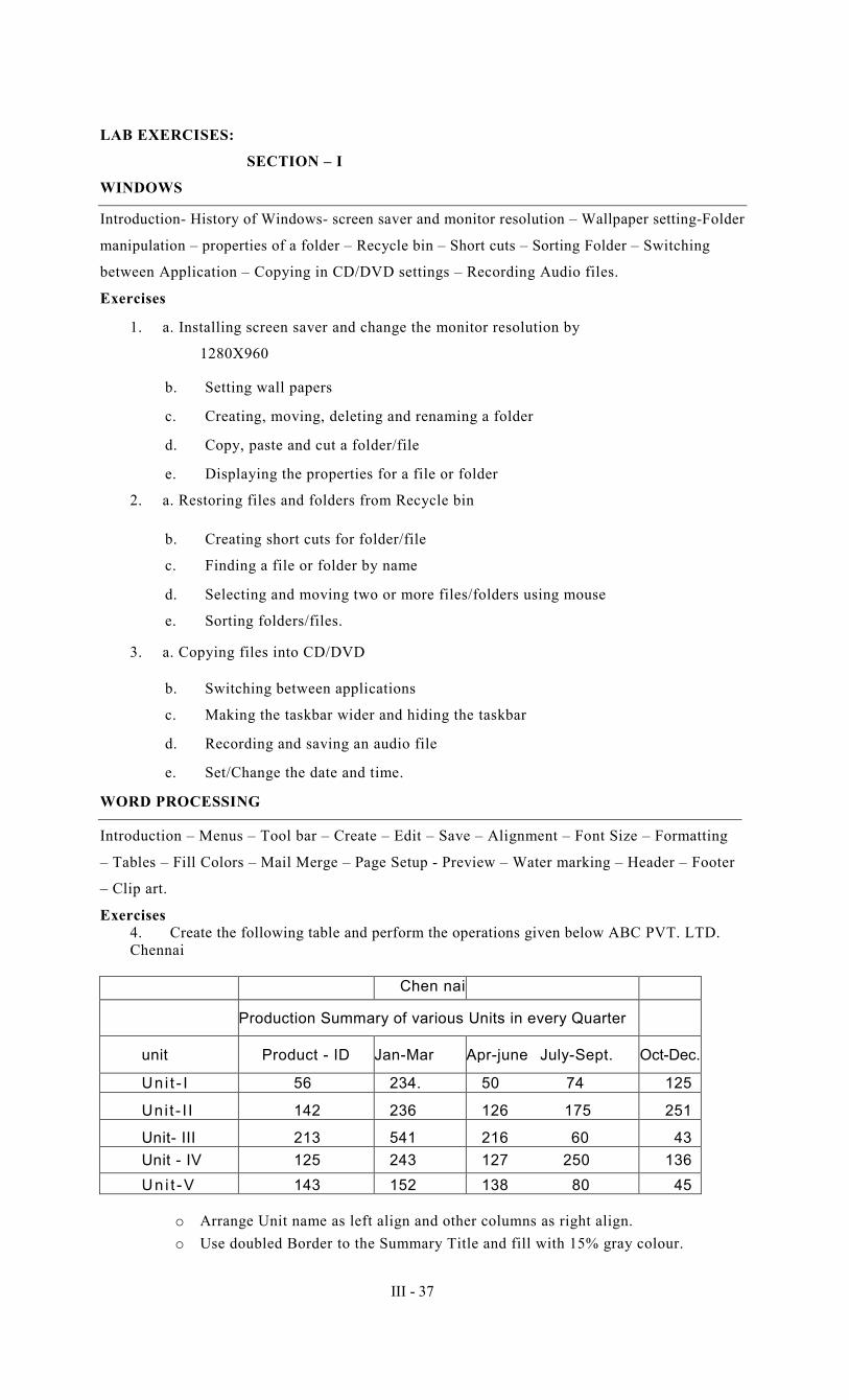
4. Create the following table and perform the operations given below ABC PVT. LTD.
Chennai
Chen nai
Production Summary of various Units in every Quarter
unit Product - ID Jan-Mar Apr-june July-Sept. Oct-Dec.
Un i t - I 56 234. 50 74 125
Uni t - I I 142 236 126 175 251
Unit- III 213 541 216 60 43
Unit - IV 125 243 127 250 136
Un i t -V 143 152 138 80 45
o Arrange Unit name as left align and other columns as right align.
o Use doubled Border to the Summary Title and fill with 15% gray colour.
III - 38
o Implement merging and splitting two or more cells
o Give alternative fore colour for columns.
o Print the above table.
5. Create a standard covering letter and use mail merge to generate the customized letters for
applying to a job in various organizations. Also, create a database and generate labels for the
applying organizations.
6. Create a news letter of three pages with two columns text. The first page contains some formatting
bullets and numbers. Set the document background colour and add ‘confidential’ as the watermark.
Give the document a title which should be displayed in the header. The header/ footer of the first
page should be different from other two pages. Also, add author name and date/time in the header.
The footer should have the page number.
SPREADSHEET
Introduction – Menus – Tool bar – Create – Edit – Save – Formatting cells – Chart wizard – Fill
Colors – Creating and using formulas – Sorting – Filtering.
Exercises:
7. Create a result sheet containing Candidate's Register No., Name, Marks for six subjects.
Calculate the total and result. The result must be calculated as below and failed candidates
should be turned to red.
Result is Distinction if Total >= 70 %
First Class if Total > = 60 % and < 70 %
Second Class if Total >= 50 % and < 60 %
Pass if Total >= 35% and < 5 0%
Fail otherwise
Create a separate table based on class by using auto filter feature.
8. Create a table of records with columns as Name and Donation Amount. Donation amount
should be formatted with two decimal places. There should be at least twenty records in
the table. Create a conditional format to highlight the highest donation with blue colour
and lowest donation with red colour. The table should have a heading.
9. Prepare line, bar and pie chart to illustrate the subject wise performance of the class for any
one semester.
SECTION –
II DATABASE
Introduction – Menus – Tool bar – Create – Edit – Save – Data types – Insert – Delete –
Update – View – Sorting and filtering – Queries – Report – Page setup – Print.
Exercises:
10. Create Database to maintain at least 10 addresses of your class mates with the
Following constraints
• Roll no. should be the primary key.
• Name should be not null
11. Prepare a payroll for employee database of an organization with the following details:
Employee Id, Employee name, Date of Birth, Department and Designation, Date of
appointment, Basic pay, Dearness Allowance, House Rent Allowance and other

III - 39
deductions if any. Perform simple queries for different categories.
12. Design a pay slip for a particular employee from the above database.
PRESENTATION
Introduction – Menus – Tool bar – Create – Edit – Save – Slide transition – Insert image – Hyper
link – Slide numbers – View slide show with sound – Photo album – Clip art.
Exercises
13. Make a marketing presentation of any consumer product with at least 10 slides. Use
different customized animation effects on pictures and clip art on any four of the ten slides.
14. Create a Presentation on “Communication Skills” with three different slide transitions
with sound effect.
15. Create a photo album in PowerPoint.
INTERNET
Introduction – Browsers – Open a website – Email: Send, receive and delete – Email with
Attachments Google docs – Search Engines – Searching topics
Exercises:
16. Create an e-mail id and perform the following
x Write an e-mail inviting your friends to your Birthday Party.
x Make your own signature and add it to the e-mail message.
x Add a word attachment of the venue route
x Send the e-mail to at least 5 of your friends.
17. Create a presentation on Google docs. Ask your friend to review it and comment on it.
Use “Discussion” option for your discussions on the presentation.
18. Find out the direction and distance about road travel from Delhi to Agra using the Internet
search. Also make a report of the Map and other details like place to stay and visit at Agra.
SAFETY PRECAUTIONS TO BE FOLLOWED BY STUDENTS
• Do not touch, connect or disconnect any plug or cable without teacher’s permission
• Don’t attempt to touch any live wires
• Systems should be shutdown properly after completion of work.
REFERENCES
TITLE AUTHOR PUBLISHER Year of
Publication
Computer Applications
Practical Manual
Dr.V.Karthikeyan
Mr.D.Arulselvan
Learning Resource Centre,
Thiagarajar
Polytechnic College,
Salem- 636 005
2012
Windows 7 in easy steps Harshad kotecha Tata McGrawHill 2011
A First Course in Computer 2003 Sanjay Sasena Vikas Publications 2009
MS Office – 2003 Ramesh Bangia Kanna Book Publication 2005
Introduction to Computers with
MS-Office 2000
Alexis Leon &
Mathews Leon
Tata McGraw-Hill
2002
Mastering Microsoft Office 2000 Gini Courter &
Annette Marquis BPB Publications 1999

III - 40
MODEL QUESTION
Term : III Time : 3 Hrs
Programme : Diploma in Mechanical Engineering (Tool & Die) Max. Marks : 75
Course : Computer applications practical Course Code : M7TD208
Answer all the questions Max.Marks :75
1 Section - I
Prepare line, bar and pie chart to illustrate the subject wise performance of the
class for any one semester.
2 Section - II
Create an e-mail id and perform the following
� Write an e-mail inviting your friends to your Birthday Party.
� Make your own signature and add it to the e-mail message.
� Add a word attachment of the venue route
� Send the e-mail to at least 5 of your friends.


![OUTER DERIVATIONS OF LIE ALGEBRAS · 1967] OUTER DERIVATIONS OF LIE ALGEBRAS 267 outer derivations is a linear sum of the outer derivations, which are obtained as in the first part](https://img.dokumen.tips/doc/110x75/5ec52027613ab73b287ddf89/outer-derivations-of-lie-algebras-1967-outer-derivations-of-lie-algebras-267-outer.jpg)