Embed Size (px)
Citation preview

Programmable transmitter of CO2 concentration
AR006655, AR006656, AR006658, AR006659
Programmable transmitter of temperature, relative humidity, CO2 and other derived humidity values
AR006657, AR005439, AR006660
with RS232 / RS485 serial output
Instruction Manual
Instruction Manual
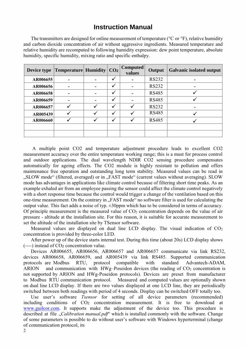
The transmitters are designed for online measurement of temperature (°C or °F), relative humidity
and carbon dioxide concentration of air without aggressive ingredients. Measured temperature and relative humidity are recomputed to following humidity expression: dew point temperature, absolute humidity, specific humidity, mixing ratio and specific enthalpy.
Device type Temperature Humidity CO2 Computed
values Output Galvanic isolated output
AR006655 - - - RS232 - AR006656 - - - RS232 - AR006658 - - - RS485
AR006659 - - - RS485
AR006657 RS232 - AR005439
RS485
RS485
AR006660
A multiple point CO2 and temperature adjustment procedure leads to excellent CO2 measurement accuracy over the entire temperature working range; this is a must for process control and outdoor applications. The dual wavelength NDIR CO2 sensing procedure compensates automatically for ageing effects. The CO2 module is highly resistant to pollution and offers maintenance free operation and outstanding long term stability. Measured values can be read in „SLOW mode“ (filtered, averaged) or in „FAST mode“ (current values without averaging). SLOW
mode has advantages in applications like climate control because of filtering short time peaks. As an example exhaled air from an employee passing the sensor could affect the climate control negatively with a short response time because the control would trigger a change of the ventilation based on this one-time measurement. On the contrary in „FAST mode“ no software filter is used for calculating the output value. This fact adds a noise of typ. ±30ppm which has to be considered in terms of accuracy. Of principle measurement is the measured value of CO2 concentration depends on the value of air pressure - altitude at the installation site. For this reason, it is suitable for accurate measurement to set the altitude of the installation site by TSensor software.
Measured values are displayed on dual line LCD display. The visual indication of CO2 concentration is provided by three-color LED.
After power up of the device starts internal test. During this time (about 20s) LCD display shows (----) instead of CO2 concentration value.
Devices AR006655, AR006656, AR006657 and AR006657 communicate via link RS232, devices AR006658, AR006659, and AR005439 via link RS485. Supported communication protocols are Modbus RTU, protocol compatible with standard Advantech-ADAM, ARION and communication with HWg–Poseidon devices (the reading of CO2 concentration is not supported by ARION and HWg-Poseidon protocols). Devices are preset from manufacturer to Modbus RTU communication protocol. Measured and computed values are optionally shown on dual line LCD display. If there are two values displayed at one LCD line, they are periodically switched between both readings with period of 4 seconds. Display can be switched OFF totally too.
Use user’s software Tsensor for setting of all device parameters (recommended) including conditions of CO2 concentration measurement. It is free to download atwww.guilcor.com. It supports make the adjustment of the device too. This procedure is described at file „Calibration manual.pdf“ which is installed commonly with the software. Change of some parameters is possible to do without user’s software with Windows hyperterminal (changeof communication protocol, its 2

3
parameters, LCD display setting). It is described in file “Description of communication protocols ”
which is free to download at the same address.
Please read instruction manual before the first device connection.
Device setting from the manufacturer
If special setting was not required in the order device is set from the manufacturer to the following parameters:
communication protocol: Modbus RTU device address: 01 communication speed: 9600Bd, without parity, 2 stop bits display: switched ON value displayed at higher line: CO2, temperature/CO2 – by device type value displayed at lower line: relative humidity temperature unit: °C
preset computed value: dew point temperaturemeasurement mode: SLOW display: switched ON LED indication: up to 1000 ppm lights green LED, between 1000 and 1200
ppm lights yellow LED and over 1200 ppm lights red LED altitude: 300 m above see level at the installation site Modification of the setting is possible to do by means of the PC and TSensor program.
Device installation
Devices (except the AR006660 are designed for wall mounting. There are two mounting holes at the sides of the case. Transmitter AR006660 install into the air-conditioning duct by clamping the metal stem into the cable gland Pg21. Also it is possible to use the installation flanges AR005316 or AR006730 (see optional accessories). Unpack the external CO2 probe (AR006656, AR006659 and AR006657 and connect it to the device. Then place the probe into the measured environment. Interconnection terminal is accessible after unscrewing four screws and removing the lid. Pass the cables through a released glands and connect the wires according to diagram. Do not forget to tighten glands and screw the lid. The working position of AR006655 and AR006658 transmitters is with cable glands (connector) upwards, the working position of AR006657 and AR005439 is with sensor cover downwards and transmitters AR006656, AR006659, AR006657, AR006660 are installed in any position.
It is not recommended to use the devices AR006657, AR005439, AR006660 and external RH+T probe of AR006657 transmitters for long time under condensation conditions. It could be the cause of
water steam condensation inside the sensor’s cover into water phase. This liquid phase stays inside sensor’s cover and can’t escape from the cover easily. It can dramatically increase response time to
relative humidity change. If water condensation occurs for longer time it can cause sensor damage. Similar effect can occur under water aerosol conditions.
4
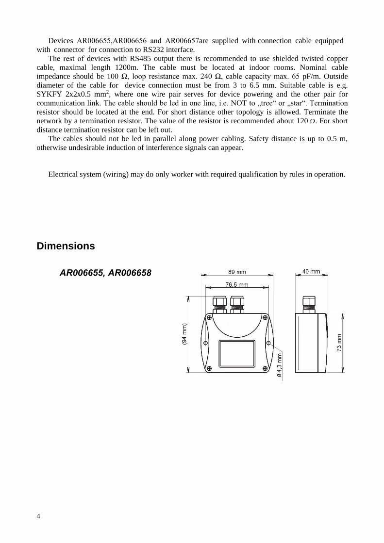
Devices AR006655,AR006656 and AR006657are supplied with connection cable equipped
with connector for connection to RS232 interface.
The rest of devices with RS485 output there is recommended to use shielded twisted copper
cable, maximal length 1200m. The cable must be located at indoor rooms. Nominal cable
impedance should be 100 Ω, loop resistance max. 240 Ω, cable capacity max. 65 pF/m. Outside
diameter of the cable for device connection must be from 3 to 6.5 mm. Suitable cable is e.g.
SYKFY 2x2x0.5 mm2, where one wire pair serves for device powering and the other pair for
communication link. The cable should be led in one line, i.e. NOT to „tree“ or „star“. Termination
resistor should be located at the end. For short distance other topology is allowed. Terminate the
network by a termination resistor. The value of the resistor is recommended about 120 Ω. For short
distance termination resistor can be left out.
The cables should not be led in parallel along power cabling. Safety distance is up to 0.5 m,
otherwise undesirable induction of interference signals can appear.
Electrical system (wiring) may do only worker with required qualification by rules in operation.
Dimensions
AR006655, AR006658

5
AR006656, AR006659
AR006657, AR005439

6

7
AR006657
Typical application wiring, connection of terminals – RS232

8
Typical application wiring, connection of terminals – RS485

9
AR006660
10
Info mode
If in doubt of setting of installed device, verification of its address is enabled even without using computer. Power should be connected. Devices with RS232 interface have address always set to one.
Unscrew device cover and shortly press button next to connection terminals (jumper should be opened). Actual adjusted address of the device is displayed on LCD display at decimal base, for HWg-Poseidon’s communication protocol there is shown number corresponding with ASCII address code. Next press of button exits info mode and actual measured values are displayed.
Note: No measurement and communication is possible during info mode. If device stays in info mode for longer than 15 s, device automatically returns to measuring cycle.
Description of communication protocols
Detailed description of each communication protocols including examples of communication is available in individual document “Description of communication protocols ” which is free to download at www.guilcor.com.
Note: After switching ON the power of the device it can last up to 2 s before the device starts to communicate and measure!
Modbus RTU
Control units communicate on master-slave principle in half-duplex operation. Only master can send request and only addressed device responds. During sending of request no other slave station should respond. During communication, data transfer proceeds in binary format. Each Byte is sent as eight bit data word in format: 1 start bit, data word 8 bit (LSB first), 2 stop bits1, without parity. Device supports communication speed from 110Bd to 115200Bd.
Sent request and response have syntax: ADDRESS OF DEVICE – FUNCTION – Modbus CRC
Supported functions 03 (0x03): Reading of 16-bit registers (Read Holding Registers) 04 (0x04): Reading of 16-bit input gates (Read Input Registers) 16 (0x10): Setting of more 16-bit registers (Write Multiple Registers)
Jumper and button Jumper and button are located next to connection terminals. If communication protocol Modbus
is selected the function of jumper and button is as follows: Jumper opened – device memory is protected from writing, from device side it is only enabled
to read measured value, writing to memory is disabled (no change of device address,communication speed and LCD setting is enabled).
Jumper closed – writing to device memory is enabled by means of User’s software. Jumper opened and button shortly pressed – device goes to Info mode, see chapter „Info
mode”.
1 Device sends two stop bits, for receive one stop bit is enough.

11
Jumper closed and button pressed for longer than six seconds – causes restoring ofmanufacturer setting of communication protocol, i.e. sets Modbus RTU communicationprotocol, device address sets to 01h and communication speed to 9600Bd - after button pressthere is “dEF” message blinking at LCD display. Six seconds later message “dEF” stays
shown, it means manufacturer setting of communication protocol is done.
Modbus registers of the device
Variable Unit Address[
hex]X
Address[
dec]X Format Size Status
Measured temperature [°C] [°F]* 0x0031 49 Int*10 BIN16 R Measured relative humidity [%] 0x0032 50 Int*10 BIN16 R Computed value * [*] 0x0033 51 Int*10 BIN16 R Dew point temperature [°C] [°F]* 0x0035 53 Int*10 BIN16 R Absolute humidity [g/m3] 0x0036 54 Int*10 BIN16 R Specific humidity [g/kg] 0x0037 55 Int*10 BIN16 R Mixing ratio [g/kg] 0x0038 56 Int*10 BIN16 R Specific enthalpy [kJ/kg] 0x0039 57 Int*10 BIN16 R CO2 concentration displayed on LCD ppm 0x0034 52 Int BIN16 R
CO2 concentration „FAST“ mode
value ppm 0x0054 84 Int BIN16 R
CO2 concentration „SLOW“ mode
value ppm 0x0055 85 Int BIN16 R
Address of device [-] 0x2001 8193 Int BIN16 R/W* Code of communication speed [-] 0x2002 8194 Int BIN16 R/W* Serial number of device Hi [-] 0x1035 4149 BCD BIN16 R Serial number of device Lo [-] 0x1036 4150 BCD BIN16 R Version of Firmware Hi [-] 0x3001 12289 BCD BIN16 R Version of Firmware Lo [-] 0x3002 12290 BCD BIN16 R
Explanation:
* depends on device setting (by User’s software)
Int*10 register is in format integer*10 R register is designed only for reading W* register is designed for writing, for details see file “Description of communication
protocols of Txxxx series” X register addresses are indexed from zero – register 0x31 is physically sent as value
0x30, 0x32 as 0x31 (zero based addressing).
Note: In case there is a need for reading of measured values from the device with higher resolution than one decimal, measured values in device are stored also in „Float“ format, which is not directly
compatible with IEEE754.
12 ie-snc-t5(6)3(4)xx-05
Protocol compatible with Advantech-ADAM standard
Control units communicate on master-slave principle in half-duplex operation. Only master can
send requests and only addressed device responds. During sending request any of slave devices should
respond. During communication data is transferred in ASCII format (in characters). Each Byte is sent
as two ASCII characters. Device supports communication speed from 1200Bd to 115200Bd,
parameters of communication link are 1 start bit + eight bit data word (LSB first) + 1 stop bit, without
parity.
Jumper Jumper is located next to connection terminals. If communication protocol compatible with
standard Advantech-ADAM is selected, its function is the following:
If jumper during switching ON the power is closed, device always communicates with
following parameters regardless stored setting in the device:
communication speed 9600 Bd, without check sum, device address 00
If jumper during switching ON the power is not closed, device communicates in accordance
with stored setting.
If jumper is closed during device operation, device temporarily changes its address to 00, it
will communicate in the same communication speed as before closing jumper and will
communicate without check sum. After jumper is opened setting of address and check sum is
reset in accordance with values stored in the device.
Communication speed and check sum are possible to change only if jumper is closed.
Jumper closed and button pressed for longer than six seconds – causes restoring of
manufacturer setting of communication protocol, i.e. sets Modbus RTU communication
protocol, device address sets to 01h and communication speed to 9600Bd - after button press
there is “dEF” message blinking at LCD display. Six seconds later message “dEF” stays
shown, it means manufacturer setting of communication protocol is done.
Command for value reading • transmitters of CO2 concentration - command for reading of measured value is
#AA(CRC) cr, where AA is device address, CRC is check sum (can be used or not)
• transmitters of temperature, relative humidity and CO2 concentration - command for
reading of measured value is #AAx(CRC) cr, where AA is device address, x is
number of communication channel, CRC is check sum (can be used or not)
Measured value Number of communication channel
Temperature 0
Relative humidity 1
Computed value 2
CO2 concentration 3
Command #AA(CRC) cr for reading all measured values at once is supported for
multi-channel devices since firmware version 02.60.
Response:
> (temperature)(relative humidity)(dew point temperature)(absolute humidity)
(specific humidity)(mixing ratio)(specific enthalpy)(CO2 concentration)cr

ie-snc-t5(6)3(4)xx-05 13
ARION communication protocol - AMiT company
The device supports communication protocol ARiON version 1.00. For more details see file
“Description of communication protocols of series” or www.amit.cz. The reading of CO2
concentration is not supported by this protocol.
Communication with HWg Poseidon units
Device supports communication with HWg-Poseidon units. For communication with this unit set
the device with setup software TSensor to communication protocol HWg–Poseidon and set correct
device address. This communication protocol supports read temperature at °C, relative humidity and
one of computed value (dew point temperature or absolute humidity). The reading of CO2
concentration is not supported by this protocol.
Jumper and button If communication with HWg Poseidon unit is selected, the function of jumper and button is as
follows:
Jumper opened and button shortly pressed – device goes to Info mode, see chapter „Infomode”.
Jumper closed and button pressed for longer than six seconds – causes restoring of
manufacturer setting of communication protocol, i.e. sets Modbus RTU communication
protocol, device address sets to 01 and communication speed to 9600Bd - after button press
there is “dEF” message blinking at LCD display. Six seconds later message “dEF” stays
shown, it means manufacturer setting of communication protocol is done.
Error States of the device
The device still make self-test. If error occurred, LCD show error code:
Error 0 - first line of LCD displays „Err0“. Check sum error of stored setting inside device’s
memory. This error appears if incorrect writing procedure to device’s memory occurred or if
damage of calibration data appeared. At this state device does not measure and calculate
values. It is a serious error, contact distributor of the device to fix.
Error 1 - measured or calculated value (except concentration of CO2) is over upper limit of
allowed full scale range. This state appears in case of:
Measured temperature is higher than approximately 600 °C (i.e. high non-measurable
resistance of temperature sensor, probably opened circuit).
Relative humidity is higher than 100%, i.e. damaged humidity sensor, or humidity
calculation of humidity is not possible (due to error during temperature measurement).
Computed value – calculation of the value is not possible (error during measurement of
temperature or relative humidity or value is over range).
Error 2 - there is a reading „Err2“ on LCD display. Measured or calculated value is below lower
limit of allowed full scale range or CO2 concentration measurement error occurred. Value read
from the device is -999.9. This state appears in case of:
14
Measured temperature is lower than approximately -210°C (i.e. low resistance of
temperature sensor, probably short circuit).
Relative humidity is lower than 0%, i.e. damaged sensor for measurement of relative
humidity, or calculation of humidity is not possible (due to error during temperature
measurement).
Computed value – calculation of computed value is not possible (error during
measurement of temperature or relative humidity).
Error 3 - there is a reading „Err3“ on LCD display upper line. Error of internal A/D converter
appeared (converter does not respond, probably damage of A/D converter). At this state device
does not measure temperature and relative humidity. This error does not affect CO2
concentration measurement. It is a serious error, contact distributor of the device.
Error 4 - there is a reading „Err4“ on LCD display. It is internal device error during initialization
of CO2 sensor. Under this condition device does not measure concentration of CO2. Value
read from device is -9999. CO2 sensor is probably damaged. It is a serious error, contact
distributor of the device.
Readings on LCD display
°C, °F - reading next to this symbol is measured temperature or error state of value.
%RH - reading next to this symbol is measured relative humidity or error state of value.
CO2 ppm reading next to this symbol is measured concentration of CO2 or error state of value.
°C / °F DP - reading next to this symbol is calculated dew point temperature or error state of value.
g/m3 - reading next to this symbol is calculated absolute humidity or error state of value.
g/kg - reading next to this symbol is calculated specific humidity or mixing ratio (depends on device
setting) or error state of value.
3 - this symbol is on if jumper is closed.
If specific enthalpy is selected, there is shown only value (number) without corresponding unit!

ie-snc-t5(6)3(4)xx-05 15
Technical parameters of the device:
RS 485 Interface:
Receiver-Input Resistance: 96 kΩ Devices on bus: max. 256 (1/8 Unit Receiver Load)
Power: 9 to 30 V Power consumption: 0.5 W during normal operation
max. 3 W for 50 ms with 15 s period
AR006655, AR006658 - CO2 transmitterConcentration of CO2:
Accuracy:: ± (50 ppm + 2 % of measuring value) at 25°C (77°F) and 1013 hPa
Range: 0 to 2000 ppm Temp. dependence: typ. 2 ppm CO2 / ºC in the range 0 to 50 ºC (32 to 122°F) Long term stability: typ. 20 ppm / year Resolution: 1 ppm
Response time: t90 < 195 s in „SLOW“ measurement mode t90 < 75 s in „FAST“ measurement mode
AR006656, AR006659 - CO2 transmitterConcentration of CO2:
Accuracy:: ± (100 ppm + 5 % of measuring value) at 25°C (77°F) and 1013 hPa Range: 0 to 10 000 ppm Temp. dependence: typ. 2 ppm CO2 / ºC in the range 0 to 50 ºC (32 to 122°F) Long term stability: typ. 20 ppm / year Resolution: 1 ppm
Response time: t90 < 195 s in „SLOW“ measurement mode t90 < 75 s in „FAST“ measurement mode
AR006657, AR005439 - temperature, relative humidity and CO2 transmitter Temperature:
Accuracy: ± 0.4 °C (±0.7 °F)
Range: -30 to +80 °C (-22 to 176 °F)
Resolution: 0.1 °C (0.2 °F)
Relative humidity:
Accuracy: ± 2.5 %RH from 5 to 95 %RH at 23 °C (73,4 °F)
Range: 0 to 100 %RH, temperature compensated Resolution: 0.1 %RH Concentration of CO2:
Accuracy:: ± (50 ppm + 2 % of measuring value) at 25°C (77°F) and 1013 hPa
Range: 0 to 2000 ppm Temp. dependence: typ. 2 ppm CO2 / ºC in the range 0 to 50 ºC (32 to 122°F) Long term stability: typ. 20 ppm / year Resolution: 1 ppm
Measuring temperature and humidity range is limited in accordance with graph below!

16
Response time measurement of temperature and relative humidity with stainless steel mesh sensor cover (F5200B) and bronze sensor cover (F0000 - selectable option), air flow 1 m/s: temperature: t90 < 6 min (temperature step 20 °C (36 °F)) relative humidity: t90 < 30 s (humidity step 65 %RH, constant temperature)
Response time measurement of CO2 concentration:
t90 < 195 s in „SLOW“ measurement mode t90 < 75 s in „FAST“ measurement mode
AR006657 - temperature, relative humidity and CO2 transmitter Temperature:
Accuracy: ± 0.4 °C (±0.7 °F) Range: -30 to +105 °C (-22 to 221 °F)
Resolution: 0.1 °C (0.2 °F)
Relative humidity:
Accuracy: ± 2.5 %RH from 5 to 95 %RH at 23 °C (73.4 °F) Range: 0 to 100 %RH, temperature compensated
Resolution: 0.1 %RH Concentration of CO2:
Accuracy:: ± (100 ppm + 5 % of measuring value) at 25°C (77°F) and 1013 hPa Range: 0 to 10 000 ppm Temp. dependence: typ. 2 ppm CO2 / ºC in the range 0 to 50 ºC (32 to 122°F) Long term stability: typ. 20 ppm / year Resolution: 1 ppm
Measuring temperature and humidity range is limited in accordance with graph below!
Response time measurement of temperature and relative humidity with stainless steel mesh sensor cover (F5200B) and bronze sensor cover (F0000 - selectable option), air flow 1 m/s: temperature: t90 < 6 min (temperature step 20 °C (36 °F)) relative humidity: t90 < 30 s (humidity step 65 %RH, constant temperature)
Response time measurement of CO2 concentration:
t90 < 195 s in „SLOW“ measurement mode t90 < 75 s in „FAST“ measurement mode
AR006660 - temperature, relative humidity and CO2 transmitter Temperature:
Accuracy: ± 0.4 °C (±0.7 °F) Range: -30 to +80 °C (-22 to 176 °F)
Resolution: 0.1 °C (0.2 °F)
Relative humidity:
Accuracy: ± 2.5 %RH from 5 to 95 %RH at 23 °C (73.4 °F) Range: 0 to 100 %RH, temperature compensated
Resolution: 0.1 %RH Concentration of CO2:
Accuracy:: ± (50 ppm + 2 % of measuring value) at 25°C (77°F) and 1013 hPa Range: 0 to 2 000 ppm Temp. dependence: typ. 2 ppm CO2 / ºC in the range 0 to 50 ºC (32 to 122°F) Long term stability: typ. 20 ppm / year Resolution: 1 ppm
Measuring temperature and humidity range is limited in accordance with graph below!
17
Response time measurement of temperature and relative humidity with stainless steel mesh
sensor cover (F5200B) and bronze sensor cover (F0000 - selectable option), air flow 1 m/s:
temperature: t90 < 6 min (temperature step 20 °C (36 °F))
relative humidity: t90 < 30 s (humidity step 65 %RH, constant temperature)
Response time measurement of CO2 concentration:
t90 < 195 s in „SLOW“ measurement mode
t90 < 75 s in „FAST“ measurement mode
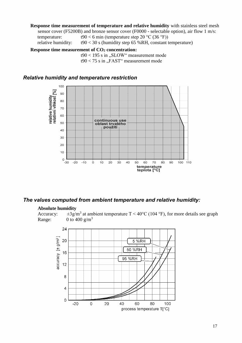
Relative humidity and temperature restriction
The values computed from ambient temperature and relative humidity: Absolute humidity Accuracy: ±3g/m3 at ambient temperature T < 40°C (104 °F), for more details see graph
Range: 0 to 400 g/m3

18
Dew point temperature
Accuracy: ±1.5 °C (±2.7 °F) at ambient temperature T < 25 °C (77 °F) and RV>30 %,
for more details see graphs bellow
Range: -60 to +80 °C (-22 to 176 °F)
Specific humidity2 Accuracy: ±2.1 g/kg at ambient temperature T < 35°C (95 °F)
Range: 0 to 550 g/kg
Mixing ratio2 Accuracy: ±2.2 g/kg at ambient temperature T < 35°C (95 °F)
Range: 0 to 995 g/kg
Specific enthalpy2 Accuracy: ± 4 kJ/kg at ambient temperature T < 25°C (77 °F)
Range: 0 to 995 kJ/kg 3
The values computed from ambient temperature and relative humidity including their
accuracy you can exactly determine by the program Conversions. It is free to download
at http://www.guilcor.com .
2 This value depends on the atmospheric pressure. For computing is used constant value stored in device memory. Default
value preset by manufacturer is 1013hPa and can be changed by user’s software. 3 This maximum is reached under conditions about 70°C/100%RH or 80°C/70%RH

19
Operating conditions Operating temperature range:
-30 to +60 °C (-22 to +140 °F)
-30 to +80 °C (-22 to +176 °F)
-30 to +60 °C (-22 to +140 °F)
-30 to +80 °C (-22 to +176 °F)
-30 to +60 °C (-22 to +140 °F)
-40 to +60 °C (-40 to +140 °F)
electronics AR006655, AR006658, AR006657, AR005439:
electronics AR006656, AR006659, AR006657:
electronics AR006660 measuring end of stem AR006657, AR005439: measuring end of stem AR006660 CO2 probe AR006656, AR006659, AR006657: RH+T probe AR006657: -30 to +105 °C (-22 to +221 °F)
It is recommended to switch off the LCD display at ambient temperatures above 70 °C.
Operating humidity range:
5 to 95 % RH (no condensation) AR006655, AR006658, AR006657, AR005439, AR006660: AR006656, AR006659, AR006657: 0 to 100 % RH (no condensation)
Operating barometric pressure range: 850 to 1100 hPaRecommended calibration interval :
2 years temperature AR006657, AR005439, AR006657, T66445: relative humidity AR006657, AR005439, AR006657, AR006660: 1 years
CO2 concentration: 5 years Protection:
IP30 IP65 IP40 IP20 IP65
electronics AR006655, AR006658, AR006657, AR005439: electronics AR006656, AR006659, AR006657, AR006660:measuring end of stem AR006657, AR005439: measuring end of stem AR006660: CO2 probe AR006656, AR006659, AR006657: RH+T probe AR006657: IP40
Working position:
with cable glands (connector) upwards any positionany position
AR006655, AR006658 AR006656, AR006659AR006657, AR005439
with sensor cover downwards. When mounting the transmitter to 19” rack with universal holder
MP046 (optional accessory) then sensor cover can be placed horizontally.
AR006660 any position - the holes in the stem must be routed in the direction of the air flow (see the picture)
EMC: EN 61326-1, EN 55011 Not allowed manipulations: It is not allowed to operate the device under conditions other than
specified in technical parameters. Devices are not designed for locations with chemically aggressive environment. Temperature and humidity sensors must not be exposed to direct contact with water or other liquids. It is not allowed to remove the sensor cover to avoid any mechanical damage of the sensors.
Storage conditions:
temperature: -40 to +60 °C (-40 to 140 °F)
relative humidity: 5 to 95 % RH (no condensation)atmospheric pressure: 700 až 1100 hPa
20
Mechanical dimensions: see dimensional drawings Weight: approximately
AR006655, AR006658 150 gAR006657, AR005439 160 g AR006656, AR006659 / 1m sonda 250 g AR006656, AR006659 / 2m sonda 280 g AR006656, AR006659 / 4m sonda 340 g AR006657/ 1m sondy 330 g AR006657/ 2m sondy 400 g AR006657 / 4m sondy 540 g AR006660 290 g Weight of devices with RS232 output is given without communication cable (weight of the cable is 70g).
Material of the case: ABS
End of operation
Device itself (after its life) is necessary to liquidate ecologically!
Technical support and service
Technical support and service is provided by distributor. For contact see warranty certificate. You can use discussion forum at web address: http://www.guilcor.com/.
21
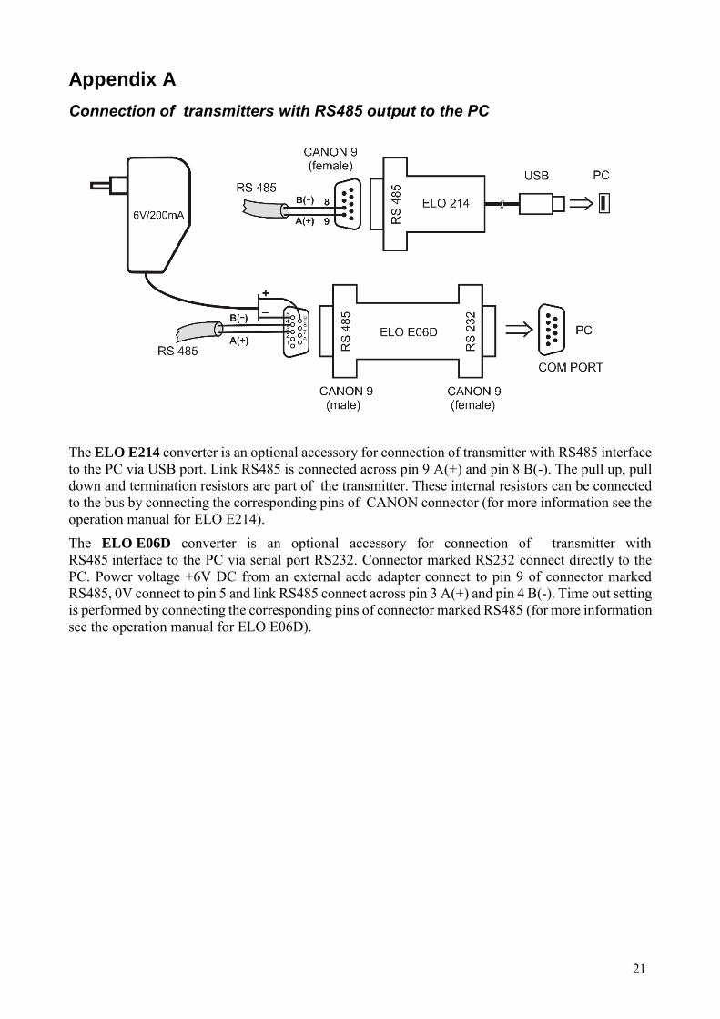
Appendix A
Connection of transmitters with RS485 output to the PC
The ELO E214 converter is an optional accessory for connection of transmitter with RS485 interface to the PC via USB port. Link RS485 is connected across pin 9 A(+) and pin 8 B(-). The pull up, pull down and termination resistors are part of the transmitter. These internal resistors can be connected to the bus by connecting the corresponding pins of CANON connector (for more information see the operation manual for ELO E214). The ELO E06D converter is an optional accessory for connection of transmitter with RS485 interface to the PC via serial port RS232. Connector marked RS232 connect directly to the PC. Power voltage +6V DC from an external acdc adapter connect to pin 9 of connector marked RS485, 0V connect to pin 5 and link RS485 connect across pin 3 A(+) and pin 4 B(-). Time out setting is performed by connecting the corresponding pins of connector marked RS485 (for more information see the operation manual for ELO E06D).