Embed Size (px)
Citation preview

Programmable DC Power Supplies5kW in 2U
Built in RS-232 & RS-485 InterfaceAdvanced Parallel Operation
Optional Interface: Compliant LAN
IEEE488.2 SCPI (GPIB) Multi-DropIsolated Analog Programming

GENESYSTM
GEN 5kW SERIES POWER
SUPPLIES
USER MANUAL
This Manual Covers Models:
GEN8-600
GEN10-500
GEN16-310
GEN20-250
GEN30-170
GEN40-125
GEN60-85
GEN80-65
GEN100-50
GEN150-34
GEN200-25
GEN300-17
GEN400-13
GEN500-10
GEN600-8.5
IA657-04-01-Rev.E
GENESYSTM
GEN 5kW SERIES POWER
SUPPLIES
USER MANUAL
This Manual Covers Models:
GEN8-600
GEN10-500
GEN16-310
GEN20-250
GEN30-170
GEN40-125
GEN60-85
GEN80-65
GEN100-50
GEN150-34
GEN200-25
GEN300-17
GEN400-13
GEN500-10
GEN600-8.5
IA657-04-01-Rev.E
IA657-04-01-Rev. M
Manual Supplement For units equipped with IEEE488.2 (GPIB) Interface option, refer to Manual IA586-04-01_.
For units equipped with LAN Interface option, refer to Manual IA672-04-01_.

This
info
rmat
ion
shee
t was
pre
pare
d ba
sed
on P
eopl
e's R
epub
lic o
f Chi
na "
Man
agem
ent M
etho
ds fo
r Con
trolli
ng P
ollu
tion
Cau
sed
by E
lect
roni
c In
form
atio
n Pr
oduc
ts R
egul
atio
n"an
d"S
J/T
1136
4—20
06 M
arki
ng fo
r Con
trol o
f Pol
lutio
n C
ause
d by
Ele
ctro
nic
Info
rmat
ion
Prod
ucts".
As P
eopl
e's R
epub
lic o
f Chi
na "
Man
agem
ent M
etho
ds fo
r Con
trolli
ng P
ollu
tion
Cau
sed
by E
lect
roni
c In
form
atio
n Pr
oduc
ts R
egul
atio
n"is
a d
iffer
ent l
egis
latio
n fr
om E
U R
oHS
Dire
ctiv
e (
2002
/95/
EC)
, inq
uirie
s con
cern
ing
EU
RoH
S D
irect
ive (
2002
/95/
EC)
info
rmat
ion
shou
ld b
e do
ne se
para
tely.
The
dat
e of
man
ufac
ture
Part
Nam
eG
EN
ESY
S, G
EN
5KW
PO
WE
R S
UPP
LY
SE
RIE
SPr
oduc
t Wei
ght
16K
g
Lead
(Pb)
Mer
cury
(Hg)
Cad
miu
m (C
d)H
exav
alen
t C
hrom
ium
(Cr6
+)Po
lybr
omin
ated
B
iphe
nyls
(PB
B)Po
lybr
omin
ated
Dip
heny
l Et
hers(
PBD
E)
0.1w
t%0.1w
t%0.01wt%
0.1w
t%0.1w
t%0.1w
t%
Cas
eO
OO
OO
OPl
astic
pan
elO
OO
OO
OPC
B's
asse
mbl
yX
OO
OO
OIn
ner m
etal
par
tsO
OO
OO
OIn
ner c
able
sO
OO
OO
OA
cces
sorie
sO
OO
OO
OPr
ovid
ed in
the
pack
age
○ : I
ndic
ates
that
the
conc
entra
tion
valu
es o
f tox
ic a
nd h
azar
dous
subs
tanc
es in
all
"hom
ogen
eous
mat
eria
ls"
of re
spec
tive
parts
and
mat
eria
ls d
oes n
ot e
xcee
d th
e co
ncen
tratio
n lim
its
regu
late
d by
"SJ
/T 1
1363
-200
6 R
equi
rem
ents
for C
once
ntra
tion
Lim
its fo
r Cer
tain
Haz
ardo
us S
ubst
ance
s in
Elec
troni
c In
form
atio
n Pr
oduc
ts".
× : I
ndic
ates
that
the
conc
entra
tion
valu
e of
a to
xic
or h
azar
dous
subs
tanc
e in
clud
ed in
a "
hom
ogen
eous
par
t" o
f a re
spec
tive
part
ot m
ater
ial e
xcee
ds th
e co
ncen
tratio
n lim
it re
gula
ted
by
"S
J/T
1136
3-20
06 R
equi
rem
ents
for C
once
ntra
tion
Lim
its fo
r Cer
tain
Haz
ardo
us S
ubst
ance
s in
Elec
troni
c In
form
atio
n Pr
oduc
ts".
Info
rmat
ion
Con
cern
ing
Incl
usio
n of
Tox
ic a
nd H
azar
dous
Sub
stan
ces
Not
esC
once
ntra
tion
Val
ues o
f Tox
ic a
nd H
azar
dous
Sub
stan
ces/
Elem
ents
(wt%
)
Subp
art N
ame

TDK-Lambda Ltd., Industrial Zone P.O.B 500 Karmiel, Israel
DECLARATION OF CONFORMITYGEN5000W SERIES
We, TDK-Lambda Ltd., located at Haharoshet St. 56 Industrial Zone P.O.B. 500 Karmiel, Israel declare under our sole responsibility that the GEN5000W series as detailed on the products covered sheet comply with the provisions of the following European Directive and are eligible to bear the CE mark:Restriction Of the use of certain Hazardous Substances Directive 2011/65/EU (RoHS2) Low Voltage Directive 2006/95/ECEMC Directive 2004/108/ECAssurance of conformance of the described product with the provisions of the stated EC Directive is given through compliance to the following standard: Electrical Safety EN 60950-1:2006+A11+A1+A12Electromagnetic Compatibility (EMC): EN 55022:1998+A1:2000+A2:2003 EN 55024:1998+A1:2001+A2:2003 EN 61000-3-3:1995+A2:2005which cover testing to the following standards:
EN 55022:1998+A1:2000+A2:2003 Conducted Emissions Class A Radiated Emissions Class A EN 61000-3-3 :1995+A2:2005 Voltage Fluctuations EN 61000-4-2 :1995+A1:1998+A2:2001 ESD AD: 8KV, CD:4KV EN 61000-4-3 :2006 Radiated Immunity 3V/m EN 61000-4-4 :2004 EFT/B Power leads: 2KV Signal leads: 0.5KV EN 61000-4-5 :2006 Conductive Surges Common mode: 2KV Differential mode 1KV EN 61000-4-6 :2007 Conducted Disturbances 3Vrms EN 61000-4-8 :1993+A1:2001 Immunity to Mag. Field 1A/m EN 61000-4-11:2004 Voltage Dips
Our European Representative in the EU is TDK-Lambda UK Limited, located at Kingsley Avenue, llfracombe, Devon, EX34 8ES UK. Further, all products covered by this declaration are manufactured in accordance with ISO9000:2008 which ensure continued compliance of the products with the requirements of the Low Voltage Directive and EMC Directive.
Name of Authorized Signatory Martin SouthamSignature of Authorized SignatoryPosition of Authorized Signatory Marketing Director EMEADate 4th April 2013Date Series first CE marked 7 January 2008Place where signed Ilfracombe, Devon, England
PRODUCTS COVERED SHEET FOR: GEN5000W series
1. GEN5000W with three phase input 190-240VAC2. GEN5000W with three phase input 380-415VAC
with rated output 0-8VDC/0-600A up to 0-600VDC/0-8.5A and total output power equial or less 5100W
Optional modules:1. IEEE (GPIB) module2. Isolated analog (V/I) module3. LAN module4. USB module

This page intentionaly left blank

WARRANTY ..........................................................................................................................................
REGULATORY NOTICES ....................................................................................................................
SAFETY INSTRUCTIONS.....................................................................................................................
GERMAN SAFETY INSTRUCTIONS ...................................................................................................
....................................................................................
1.1 OPERATION MANUAL CONTENT .................................................................................................
1.2 INTRODUCTION .............................................................................................................................
1.2.1 General description ................................................................................................................
1.2.2 Models covered ......................................................................................................................
1.2.3 Features and options .............................................................................................................
1.2.4 Multiple output power system .................................................................................................
1.2.5 Control via the serial communication port ..............................................................................
1.2.6 Analog voltage programming and monitoring .................................................................. ......
1.2.7 Parallel operation ...................................................................................................................
1.2.8 Output connections ................................................................................................................
1.2.9 Cooling and mechanical construction ....................................................................................
1.3 ACCESSORIES ...............................................................................................................................
1.3.1 General ..................................................................................................................................
1.3.2 Serial link cable ......................................................................................................................
1.3.3 Misc. hardware .......................................................................................................................
1.3.4 AC cables ...............................................................................................................................
...................................................................................................
2.1 OUTPUT RATING ...........................................................................................................................
2.2 INPUT CHARACTERISTICS ..........................................................................................................
2.3 CONSTANT VOLTAGE MODE .......................................................................................................
2.4 CONSTANT CURRENT MODE ......................................................................................................
2.5 ANALOG PROGRAMMING AND MONITORING ............................................................................
2.6 PROGRAMMING AND READBACK ...............................................................................................
2.7 PROTECTIVE FUNCTIONS ...........................................................................................................
2.8 FRONT PANEL ................................................................................................................................
2.9 ENVIRONMENTAL CONDITIONS ..................................................................................................
2.10 MECHANICAL ..............................................................................................................................
2.11 SAFETY/EMC ...............................................................................................................................
2.12 SUPPLEMENTAL CHARACTERISTICS .......................................................................................
2.13 OUTLINE DRAWINGS .................................................................................................................
.......................................................................................................
3.1 GENERAL .......................................................................................................................................
3.2 PREPARATION FOR USE ..............................................................................................................
3.3 INITIAL INSPECTION .....................................................................................................................
3.4 RACK MOUNTING ..........................................................................................................................
3.4.1 To install the power supply in a rack .......................................................................................
3.4.2 Rack mount slides ..................................................................................................................
3.5 LOCATION MOUNTING AND COOLING .......................................................................................
3.6 AC SOURCE REQUIREMENTS .....................................................................................................
3.7 AC INPUT POWER CONNECTION ................................................................................................
3.7.1 AC input connector..................................................................................................................
3.7.2 AC input cord ..........................................................................................................................
3.7.3 AC input wire connection.........................................................................................................
3.8 TURN-ON CHECKOUT PROCEDURE ...........................................................................................
3.8.1 General ...................................................................................................................................
3.8.2 Prior to operation ...................................................................................................................
3.8.3 Constant voltage check ..........................................................................................................
3.8.4 Constant current check ..........................................................................................................
3.8.5 OVP check .............................................................................................................................
3.8.6 UVL check ..............................................................................................................................
3.8.7 Foldback check ......................................................................................................................
3.8.8 Address setting ......................................................................................................................
3.8.9 Baud rate setting ....................................................................................................................
CHAPTER 1 GENERAL INFORMATION
CHAPTER 2 SPECIFICATIONS
CHAPTER 3 INSTALLATION
TABLE OF CONTENTS
Pg.7
Pg.7
Pg.7
Pg.7
Pg.7
Pg.7
Pg.8
Pg.8
Pg.8
Pg.8
Pg.8
Pg.9
Pg.9
Pg.9
Pg.9
Pg.9
Pg.9
Pg.10
Pg.10
Pg.10
Pg.10
Pg.10
Pg.10
Pg.11
Pg.11
Pg.11
Pg.11
Pg.11
Pg.11
Pg.12
Pg.13
Pg.14
Pg.14
Pg.14
Pg.14
Pg.14
Pg.14
Pg.15
Pg.15
Pg.15
Pg.15
Pg.16
Pg.16
Pg.16
Pg.17
Pg.17
Pg.17
Pg.18
Pg.18
Pg.18
Pg.18
Pg.19
Pg.19
Pg.19
Pg.1
Pg.2
Pg.3
Pg.5

3.9 CONNECTING THE LOAD ..........................................................................................................
3.9.1 Load Wiring ..........................................................................................................................
3.9.2 Current Carrying Capacity ...................................................................................................
3.9.3 Wire termination .................................................................................................................
3.9.4 Noise and Impedance Effects ..............................................................................................
3.9.5 Inductive loads .....................................................................................................................
3.9.6 Making the load connections ................................................................................................
3.9.7 Connecting single loads, local sensing (default) ..................................................................
3.9.8 Connecting single loads, remote sensing ............................................................................
3.9.9 Connecting multiple loads, radial distribution method ..........................................................
3.9.10 Multiple loads connection with distribution terminals .........................................................
3.9.11 Grounding outputs .............................................................................................................
3.10 LOCAL AND REMOTE SENSING .............................................................................................
3.10.1 Sensing wiring ...................................................................................................................
3.10.2 Local sensing .....................................................................................................................
3.10.3 Remote sensing .................................................................................................................
3.10.4 J2 sense connector technical information ..........................................................................
3.11 REPACKAGING FOR SHIPMENT .............................................................................................
...............
4.1 INTRODUCTION ..........................................................................................................................
4.2 FRONT PANEL CONTROLS AND INDICATORS ........................................................................
4.3 REAR PANEL ...............................................................................................................................
4.4 REAR PANEL SW1 SETUP SWITCH .........................................................................................
4.4.1 SW1 positions functions ......................................................................................................
4.4.2 Resetting the switch .............................................................................................................
4.5 REAR PANEL J1 PROGRAMMING AND MONITORING CONNECTOR ....................................
4.5.1 Making J1 connections ........................................................................................................
.............................................................................................
5.1 INTRODUCTION ..........................................................................................................................
5.2 STANDARD OPERATION ............................................................................................................
5.2.1 Constant Voltage Mode .......................................................................................................
5.2.2 Constant Current Operation .................................................................................................
5.2.3 Automatic Crossover ............................................................................................................
5.3 OVER VOLTAGE PROTECTION (OVP) ......................................................................................
5.3.1 Setting the OVP level ..........................................................................................................
5.3.2 Activated OVP protection indications ...................................................................................
5.3.3 Resetting the OVP circuit .....................................................................................................
5.4 UNDER VOLTAGE LIMIT (UVL) ..................................................................................................
5.4.1 Setting the UVL level ...........................................................................................................
5.5 FOLDBACK PROTECTION ..........................................................................................................
5.5.1 Setting the Foldback protection ...........................................................................................
5.5.2. Resetting activated Foldback protection ............................................................................
5.6 OUTPUT ON/OFF CONTROL ......................................................................................................
5.7 OUTPUT SHUT-OFF (SO) CONTROL VIA REAR PANEL J1 CONNECTOR ..............................
5.8 ENABLE/DISABLE CONTROL VIA REAR PANEL J1 CONNECTOR ..........................................
5.9 CV/CC SIGNAL .............................................................................................................................
5.10 PS_OK SIGNAL ..........................................................................................................................
5.11 SAFE START AND AUTO-RESTART MODES ............................................................................
5.11.1 Automatic start mode .........................................................................................................
5.11.2 Safe start mode ..................................................................................................................
5.12 OVER TEMPERATURE PROTECTION (OTP) ..........................................................................
5.13 LAST SETTING MEMORY .........................................................................................................
5.14 SERIES OPERATION .................................................................................................................
5.14.1 Series connection for increased output voltage .................................................................
5.14.2 Series connection for positive and negative output voltage ...............................................
5.15 PARALLEL OPERATION ............................................................................................................
5.16 DAISY-CHAIN CONNECTION ....................................................................................................
5.17 FRONT PANEL LOCKING ..........................................................................................................
CHAPTER 4 FRONT AND REAR PANEL CONTROLS AND CONNECTORS
CHAPTER 5 LOCAL OPERATION
TABLE OF CONTENTS
Pg.19
Pg.19
Pg.19
Pg.20
Pg.21
Pg.21
Pg.21
Pg.24
Pg.24
Pg.24
Pg.25
Pg.25
Pg.26
Pg.26
Pg.26
Pg.27
Pg.27
Pg.27
Pg.28
Pg.28
Pg.28
Pg.30
Pg.31
Pg.32
Pg.32
Pg.33
Pg.33
Pg.35
Pg.35
Pg.35
Pg.35
Pg.35
Pg.36
Pg.36
Pg.36
Pg.36
Pg.36
Pg.37
Pg.37
Pg.37
Pg.37
Pg.37
Pg.37
Pg.37
Pg.38
Pg.38
Pg.38
Pg.39
Pg.39
Pg.39
Pg.39
Pg.39
Pg.39
Pg.40
Pg.41
Pg.42
Pg.44
Pg.44

CHAPTER 6 REMOTE ANALOG PROGRAMMING
CHAPTER 7 RS232 & RS485 REMOTE CONTROL
CHAPTER 8 ISOLATED ANALOG PROGRAMMING OPTION
CHAPTER 9 MAINTENANCE
.................................................................6.1 INTRODUCTION ...........................................................................................................................6.2 LOCAL/REMOTE ANALOG CONTROLL.......................................................................................6.3 LOCAL/REMOTE ANALOG INDICATION......................................................................................6.4 REMOTE VOLTAGE PROGRAMMING OF OUTPUT VOLTAGE AND CURRENT LIMIT .............6.5 RESISTIVE PROGRAMMING OF OUTPUT VOLTAGE AND CURRENT LIMIT ...........................6.6 REMOTE MONITORING OF OUTPUT VOLTAGE AND CURRENT .............................................
...............................................................7.1 INTRODUCTION ...........................................................................................................................7.2 CONFIGURATION .........................................................................................................................
7.2.1 Default setting .......................................................................................................................7.2.2 Address setting .....................................................................................................................7.2.3 RS232 or RS485 selection ...................................................................................................7.2.4 Baud rate setting ...................................................................................................................7.2.5 Setting the unit into Remote or Local mode ..........................................................................7.2.6 RS232/458 port at Local mode .............................................................................................7.2.7 Front panel in Remote mode ................................................................................................
7.3 REAR PANEL RS232/485 CONNECTOR ......................................................................................7.4 CONNECTING POWER SUPPLIES TO RS232 OR RS485 BUS .................................................
7.4.1 Single power supply ..............................................................................................................7.4.2 Multi power supplies connection to RS232 or RS485 bus ....................................................
7.5 COMMUNICATION INTERFACE PROTOCOL ..............................................................................7.5.1 Data format ...........................................................................................................................7.5.2 Addressing ............................................................................................................................7.5.3 End of message ....................................................................................................................7.5.4 Command repeat .................................................................................................................7.5.5 Checksum .............................................................................................................................7.5.6 Acknowledge .........................................................................................................................7.5.7 Error message ......................................................................................................................7.5.8 Backspace ............................................................................................................................
7.6 ERROR MESSAGES .....................................................................................................................7.7 COMMAND SET DESCRIPTION ..................................................................................................
7.7.1 General guides .....................................................................................................................7.7.2 Command set categories ......................................................................................................7.7.3 Initialization control commands .............................................................................................7.7.4 ID control commands ............................................................................................................7.7.5 Output control commands .....................................................................................................7.7.6 Global output commands.......................................................................................................7.7.7 Status control commands .....................................................................................................
7.8 STATUS, ERROR AND SRQ REGISTERS ...................................................................................7.8.1 General .................................................................................................................................7.8.2 Conditional registers .............................................................................................................7.8.3 Service Request: Enabled and Event Registers ...................................................................
7.9 SERIAL COMMUNICATION TEST SET-UP ................................................................................................................................
8.1 INTRODUCTION ...........................................................................................................................8.2 SPECIFICATIONS .........................................................................................................................
8.2.1 0-5V/0-10V option .................................................................................................................8.2.2 4-20mA option .......................................................................................................................
8.3 ISOLATED PROGRAMMING & MONITORING CONNECTOR ....................................................8.4 SETUP AND OPERATING INSTRUCTIONS .................................................................................
8.4.1 Setting up the power supply for 0-5/0-10V Isolated Programming and Monitoring ...............8.4.2 Setting up the power supply for 4-20mA Isolated Programming and Monitoring ..................
......................................................................................................9.1 INTRODUCTION ...........................................................................................................................9.2 UNITS UNDER WARRANTY .........................................................................................................9.3 PERIODIC MAINTENANCE ..........................................................................................................9.4 ADJUSTMENT AND CALIBRATION .............................................................................................9.5 PARTS REPLACEMENT AND REPAIRS .......................................................................................9.6 TROUBLESHOOTING ...................................................................................................................9.7 FUSE RATING ...............................................................................................................................
CHAPTER 9 GERMAN TRANSLATION.........................................................................................USER MANUAL INDEX .........................................................................................................................
TABLE OF CONTENTSPg.45Pg.45Pg.45Pg.45Pg.46Pg.47Pg.48Pg.49Pg.49Pg.49Pg.49Pg.49Pg.49Pg.49Pg.49Pg.50Pg.50Pg.50Pg.51Pg.51Pg.52Pg.52Pg.52Pg.52Pg.52Pg.52Pg.52Pg.52Pg.53Pg.53Pg.53Pg.53Pg.53Pg.53Pg.54Pg.54Pg.54Pg.56Pg.57Pg.58Pg.58Pg.58Pg.59Pg.62Pg.63Pg.63Pg.63Pg.63Pg.63Pg.64Pg.65Pg.65Pg.65
Pg.67Pg.66
Pg.67Pg.67Pg.67Pg.67Pg.67Pg.67Pg.68Pg.68Pg.72
8.5 PARALLEL OPERATION WITH ISOLATED ANALOG OPTION...............................................................

This page intentionaly left blank

1
WARRANTY This TDK-Lambda Ltd. product is warranted against defects in materials and workmanship for a period offive years from date of shipment. During the warranty period, TDK-Lambda Ltd. will, at it's option, either repair or replace products which prove to be defective.
LIMITATION OF WARRANTYThe warranty shall not apply to defects resulting from improper or inadequate usage or maintenance by the buyer, buyer supplied products or interfacing. The warranty shall not apply to defects resulting from unauthorized modifications or from operation exceeding the environmental specifications of the product or if the QA seal has been removed or altered by anyone other than TDK-Lambda Ltd. authorized personnel. TDK-Lambda Ltd. does not warrant the buyers circuitry or malfunctions of TDK-Lambda Ltd. products resulting from the buyer's circuitry. Furthermore, TDK-Lambda Ltd. does not warrant any damage occurring as a result ofthe buyer's circuitry or the buyer's - supplied products. No other warranty is expressed or implied.
WARRANTY SERVICEThis product must be returned to an authorized TDK-Lambda Ltd. service facility for repairs or other warranty service. For products returned to TDK-Lambda Ltd. for warranty service, the buyer shall prepay shipping charges to TDK-Lambda Ltd. and TDK-Lambda Ltd. shall pay the shipping charges to return the product to the buyer. Refer to section 3.11 for repackaging for shipment.
DISCLAIMERThe information contained in this document is subject to change without notice. TDK-Lambda Ltd. shall not be liable for errors contained in this document or for incidental or consequential damages in connection with the furnishing, performance or use of this material. No part of this document may be photocopied, reproduced or translated into another language without the prior written consent of TDK-Lambda Ltd..
TRADEMARK INFORMATIONGenesys™ power supply is a trademark of TDK-Lambda Ltd. & TDK- Lambda Americas Inc.Microsoft™ and Windows™ are trademarks of Microsoft Corporation.

2
REGULATORY NOTICES
2
FCC Notice
This device complies with Part 15 of the FCC Rules. Operation is subject to the following two
conditions: (1) this device may not cause harmful interference, and (2) this device must accept any
interference received, including interference that may cause undesired operation.
CE Notice (European Union)
Marking by the CE Symbol indicates compliance to the EMC Directive and the Low Voltage
Directive of the European Union. Such marking is indicative that the Genesys series GEN5000W
meets the following technical standards:
EN 55022:2010 Information technology equipment - Radio disturbance characteristics -
Limits and methods of measurement.
EN 55024:2010 Information thecnology equipment - Immunity characteristics - Limits and
methods of measurement.
EN 60950-1:2006+A11:2009 + A1:2010 + A12:2011 Information technology equipment -
Safety - Part 1: General requirements.
A “Declaration of Conformity” in accordance with the preceding directives and standards has been
made and is on file at our EU representative TDK-Lambda Limited, located at Kingsley Avenue,
Ilfracombe, Devon EX34 8ES, UK.
TM
�
�
�
NOTE: This equipment has been tested and found to comply with the limits for a Class A digital
device, pursuant to Part 15 of the FCC Rules. These limits are designed to provide reasonable
protection against harmful interference when the equipment is operated in a commercial
environment. This equipment generates, uses, and can radiate radio frequency energy and, if not
installed and used in accordance with the instruction manual, may cause harmful interference to
radio communications. Operation of this equipment in a residential area is likely to cause harmful
interference in which case the user will be required to correct the interference at his own expense.
WARNING: Modifications not expressly approved by the party responsible for compliance could
void the user’s authority to operate the equipment under FCC Rules.
WARNING: This is a Class A product. On a domestic environment this product may cause radio
interference in which case user may be required to take adequate measures.
SAFETY APPROVALS:
UL 60950-1 Second Edition, UL Listed, C-UL for Canada, IEC 60950-1 Second Edition, CE
marking, when applied to the GEN5000W product, indicates compliance with the Low Voltage
Directive 2006/95/EC in that it complies with EN 60950-1 Second Edition.

3
SAFETY INSTRUCTIONS
CAUTION
INSTALLATION CATEGORY
GROUNDING
FUSES
INPUT RATINGS
LIVE CIRCUITS
PARTS SUBSTITUTIONS & MODIFICATIONS
The following safety precaution must be observed during all phases of operation, service and repairof this equipment. Failure to comply with the safety precautions or warnings in this documentviolates safety standards of design, manufacture and intended use of this equipment and mayimpair the built-in protections within.TDK-Lambda Ltd. shall not be liable for user’s failure to comply with these requirements.
The Genesys power supply series has been evaluated to INSTALLATION CATEGORY II.Installation category (over voltage category) II: local level, appliances, portable equipment etc.. Withsmaller transient over voltage than Installation Category (over voltage category) III.
This product is a Safety Class 1 instrument. To minimize shock hazard, the instrument chassis mustbe connected to an electrical ground. The instrument must be connected to the AC power supplymains through a three conductor power cable for Single Phase models and through a four conductorpower cable for Three Phase models with the ground wire firmly connected to an electrical ground(safety ground) at the power outlet.For instruments designed to be hard-wired to the supply mains, the protective earth terminal mustbe connected to the safety electrical ground before another connection is made. Any interruption ofthe protective ground conductor, or disconnection of the protective earth terminal will cause apotential shock hazard that might cause personal injury.
There is a potential shock hazard at the RS232/485 and the IEEE ports when using power supplieswith rated or combined voltage greater than 400V and the Positive Output of the Power Supply isgrounded. Do Not connect the Positive Output to ground when using the RS232/485 or IEEE.
Fuses must be changed by authorized TDK-Lambda Ltd. service personnel only. For continuedprotection against risk of fire, replace only with the same type and rating of fuse. Refer tomaintenance instructions in chapter 9 for fuses rating.
The GenesysTM power supply units have fuses in all supply conductots. To prevent potential riskof hazard during servicing, the unit shall be fully disconnected from the supply.
Do not use AC supply which exceeds the input voltage and frequency rating of this instrument. Theinput voltage and frequency rating of the Genesys power supply series is:190-240V~, 50/60Hz forThree Phase 200V models and 380-415V~, 50/60Hz for Three Phase 400V models. For safetyreasons, the mains supply voltage fluctuations should not exceed +/-10% of nominal voltage.
Operating personnel must not remove the instrument cover. No internal adjustment or componentreplacement is allowed by non-TDK-Lambda Ltd. qualified personnel. Never replace components withpower cable connected. To avoid injuries, always disconnect power , discharge circuits and removeexternal voltage source before touching components.
Parts substitutions and modifications are allowed by authorized TDK-Lambda Ltd.service personnelonly. For repairs or modifications, the instrument must be returned to TDK-Lambda Ltd.service facility.
TM
TM
WARNINGOUTPUT TERMINAL GROUNDING
CAUTION MULTI POLE FUSING
3

4
SAFETY INSTRUCTIONS.
ENVIRONMENTAL CONDITIONS
The Genesys power supply series safety approval applies to the following operating conditions:
*Indoor use *Ambient temperature: 0 C to 50 C
*Maximum relative humidity: 90% (no condensation) *Altitude: up to 3000m
*Pollution degree 2
TM
o o
4
!
Instruction manual symbol. The
instrument will be marked with this
symbol when it is necessary for the
user to refer to the instruction
manual.
CAUTION Risk of Electrical Shock.
Indicates hazardous voltage.
Indicates ground terminal.
Protective Ground Conductor Terminal
Off (Supply)
On (Supply)
Direct Current (DC)
Alternative Current (AC)
Three-PhaseAlternating Current
Standby (Supply)
The WARNING sign denotes a hazard.An attention to a procedure is called.
Not following procedure correctly could result in personal injury.
AWARNING sign should not be skipped and all indicated conditions must be
fully understood and met.
The CAUTION sign denotes a hazard. An attention to a procedure is called. Not
following procedure correctly could result in damage to the equipment. Do not proceed
beyond a CAUTION sign until all indicated conditions are fully understood and met.
Do not use this product in environments with strong Electromagnetic field, corrosive
gas and conductive materials.
WARNING
CAUTION
CAUTION
3~
- - -
~

5

6

7
CHAPTER 1 GENERAL INFORMATION
1.1 USER MANUAL CONTENT
1.2 INTRODUCTION
This user’s manual contains the operating instructions, installation instructions and specifications of
the Genesys 5000W power supply series. The instructions refer to the standard power supplies,
including the built-in RS232/485 serial communication. For information related to operation with the
optional IEEE programming, refer to User Manual for Power Supply IEEE Programming Interface.
Genesys power supplies are wide output range, high performance switching power supplies. The
Genesys series is power factor corrected and operates from worldwide AC voltage range. Output
voltage and current are continuously displayed and LED indicators show the complete operating
status of the power supply. The Front panel controls allow the user to set the output parameters, the
protection levels (Over-Voltage protection, Under-Voltage limit and Foldback) and preview the
settings. The rear panel includes the necessary connectors to control and monitor the power supply
operation by remote analog signals or by the built-in serial communication (RS232/485). GPIB
programming and Isolated-Analog programming/monitoring are optional.
Models with rated output from 0-8VDC/0-600A to 0-600VDC/0-8.5A.
Constant Voltage / Constant Current with automatic crossover.
* Active Power Factor correction.
* Single Phase or Three Phase options.
* Embedded Microprocessor Controller.
* Built in RS232/485 Interface.
* Voltage & Current high resolution adjustment by digital encoders.
* High accuracy programming/readback-16 bit.
* Software Calibration (no internal trimmers / potentiometers).
* Last Setting Memory.
* Independent Remote ON/OFF (opto-isolated) and Remote Enable/Disable.
TM
TM
TM
1.2.1 General description
1.2.2 Models covered by this manual
1.2.3 Features and options
*
7

8
* Parallel operation (Master/Slave) with Active current sharing.
* Remote sensing to compensate for voltage drop of power leads.
* Cooling fan speed control for low noise and extended fan life.
* Zero stacking- no ventillation holes at the top and bottom surface of the power supply.
* Optional GPIB interface (SCPI compatible).
* Optional Isolated Analog programming/monitoring (0-5V or 0-10V, user selectable
and 4-20mA).
The Genesys power supplies series can be configured into a programmable power
system of up to 31 units using the built-in RS232/RS485 communication port in the power
supply and the RS485 linking cable provided with each power supply.
In a GPIB system, each power supply can be controlled using the optional GPIB controller
(factory installed).
The following parameters can be programmed via the serial communication port:
1. Output voltage setting.
2. Output current setting.
3. Output voltage measurement.
4. Output on/off control.
5. Output current measurement.
6. Foldback protection setting.
7. Over-voltage protection setting and readback.
8. Under-Voltage limit setting and readback.
9. Power-supply start up mode (last setting or safe mode)
Analog inputs and outputs are provided at the rear panel for analog control of the power
supply. The output voltage and the current limit can be programmed by analog voltage or by
resistor, and can be monitored by analog voltage. The power supply output can be remotely
set to On or Off and analog signals monitor the proper operation of the power supply and the
mode of operation (CV/CC).
Genesys power supplies of the same output voltage and current rating can be paralleled in
master-slave configuration with automatic current sharing to increase power available.
Output connections are made to rear panel bus-bars for models up to 100V and to a 4-
terminal wire clamp connector for models above 100V rated output voltage. Either the
positive or negative terminal may be grounded or the output may be floated. Models up to
60VDC Rated Output shall not float outputs more than +/- 60VDC above/below chassis
ground. Models >60VDC Rated Output shall not float outputs more than +/-600VDC
above/below chassis ground. Contact factory for assistance with higher float voltage
applications.
Local or remote sense may be used. In remote sense, the voltage drop on the load wires
should be minimized. Refer to the specifications for the maximum voltage drop value.
* External Analog Programming and Monitoring standard (0-5V or 0-10V, user selectable).
1.2.4 Multiple output power system
1.2.5 Control via the serial communication port
1.2.6 Analog voltage programming and monitoring
1.2.7 Parallel operation
TM
TM
1.2.8 Output connections
8

9
1.2.9 Cooling and mechanical construction
1.3.1 General
1.3.2 Serial link cable
1.3.4 AC cables
The Genesys series is cooled by internal fans. At the installation, care must be taken to
allow free air flow into the power supply via the front panel and out of the power supply via
the rear panel. The Genesys power supplies have a compact and lightweight package
which allows easy installation and space saving in the application equipment.
Accessories are delivered with the power supply or separately upon ordering. The list below
shows the possible accessories and ordering numbers.
S
TM
TM
1.3 ACCESSORIES
erial link cable, for linking power supplies by RS485 communication is provided with the
power supply.
Cable description: 0.5m length, shielded, RJ-45 type plugs, 8 contacts (P/N: GEN/RJ45).
*AC Input plug connector (Phoenix Contact, PC 6/4-STF-10,16)
* Output terminal shield
* Plastic legs for bench mounting.
AC cables are not provided with the power supply.
Refer to Table1-1 for recommended AC input cables (customer supplied). Add a non-locking
plug approved by the national safety standards of the country of usage.
1.3.3 Misc. hardware
* Strain relief forAC cord
* DB25 plug kit (AMP, 749809-9).
9
Observe all torque guidelines within this manual. Over torqueing may damage
unit or accessories. Such damage is not covered under manufacturers warranty.
CAUTION
Min 4x12AWG (3 wire plus safety ground),
stranded copper, 300V, 60 c minimum, rated for
25A. 3m max. length, outer diameter: 9~11mm.
O
Min 4x14AWG (3 wire plus safety ground),
stranded copper, 600V, 60 c minimum, rated for
15A. 3m max. length, outer diameter: 9~11mm.
O
190-240V~ , Three Phase
380-415V~ , Three Phase
AC Input Range AC Input Cable
Table 1-1: Recommended AC input cable

10
CHAPTER 2 SPECIFICATIONS
1.Vout voltage programming
2.Iout voltage programming (*13)
3.Vout resistor programming
4.Iout resistor programming (*13
5.On/off control
6.Output current monitor (*13)
7.Output voltage monitor
8.Power supply OK signal
9.Parallel operation
10.Series operation
11.CV/CC indicator
12.Enable/Disable
13.Local/Remote analog control
14.Local/Remote analog indicator
)
2.5 ANALOG PROGRAMMING AND MONITORING
---
---
---
---
---
---
---
---
---
---
---
---
---
---
0~100%, 0~5V or 0~10V, user selectable. Accuracy and linearity: +/-0.5% of rated Vout.
0~100%, 0~5V or 0~10V, user selectable. Accuracy and linearity: +/-1% of rated Iout.
0~100%, 0~5/10Kohm full scale, user selectable. Accuracy and linearity: +/-1% of rated Vout.
0~100%, 0~5/10Kohm full scale, user selectable. Accuracy and linearity: +/-1.5% of rated Iout.
By electrical Voltage: 0~0.6V/2~15V or dry contact, user selectable logic.
0~5V or 0~10V, user selectable. Accuracy: +/-1%.
0~5V or 0~10V, user selectable. Accuracy : +/-1%.
4~5V-OK, 0V-Fail. 500ohm series resistance.
Possible , up to 4 units in master/slave mode with two wires current balance connection.
Possible (with external diodes), up to 2 units. 600Vdc max.from chassis ground.
Open collector. CC mode: On, CV mode: Off. Maximum voltage : 30V, maximum sink current: 10mA
Dry contact. Open: Off, Short: On. Max. voltage at Enable/Disable in: 6V.
By electrical signal or Open/Short: 0~0.6V or short: Remote, 2~15V or open: Local.
Open collector. Local: Open, Remote: On. Maximum voltage: 30V, maximum sink current: 10mA.
2.1 OUTPUT RATING
1.Rated output voltage(1*)
2.Rated output current (*2)
3.Rated output power
V
A
W
MODEL GEN 8-600
8
600
4800
10-500
10
500
5000
16-310
16
310
4960
20-250
20
250
5000
30-170
30
170
5100
40-125
40
125
5000
60-85
60
85
5100
80-65
80
65
5200
100-50
100
50
5000
150-34
150
34
5100
200-25
200
25
5000
300-17
300
17
5100
400-13
400
13
5200
500-10
500
10
5000
600-8.5
600
8.5
5100
10
2.2 INPUT CHARACTERISTICS
3-Phase, 200V models:
3-Phase, 400V models:
---
---
%
0.94 @200/380Vac, rated output power.
3-Phase, 200V models: 170~265Vac, 47~63Hz
3-Phase, 400V models: 342~460Vac, 47~63Hz
3-Phase 200V models: Less than 50A
3-Phase 400V models: Less than 20A
V 8 10 16 20 30 6040 150 200 300 50010080 600400
21
10.5
22
11
22
11
22
12
22
11
22
11
22
11
22
11
22
11
22
11
22
11
22
11
22
11
22
11
22
11
3.Power Factor (Typ)
4.Efficiency (*4)
5.Inrush current (*5)
2.Maximum
Input current
at 100% load
1.Input voltage/freg. (*3)
---
A
83 84 84 86 8886 888890 88 88 88 88 88 88
8 10 16 3020 40 60 80 150100 200 300 400 500 6002.3 CONSTANT VOLTAGE MODE
1.Max. Line regulation (*6)
2.Max. Load regulation (*7)
3.Ripple and noise (p-p , 20MHz) (*8)
4.Ripple r.m.s., 5Hz~1MHz
5.Temperature coefficient
6.Temperature stability
7.Warm-up drift
8.Remote sense compensation/wire
9.
11.Transient response time
12.Hold-up time (Typ)
Up-prog. response time, 0~Vomax.(*9)
10.Down-prog. response time Full load(*9)
No load(*10)
V
---
---
mV
mV
---
---
V
mS
PPM/ Co
mS
mS
mS
0.01% of rated output voltage
0.015% of rated output voltage +5mV
75
8
70
10
75
8
75
10
70
8
80
15
120
20
200
60
300
70
350
70
450
100
70
10
70
8
90
15
200
45
50PPM/ C from rated output voltage, following 30 minutes warm-up.O
0.01% of rated Vout over 8 hrs interval following 30 minutes warm-up. Constant line, load & temp.
Less than 0.05% of rated output voltage +2mV over 30 minutes following power on.
2 2 2 2 5 5 55 5 5 5 5 5
65
135
5
80
170
5
100
20015
30
50
400 500 600 700
80
800 900
100
50
1000 1200 1500 2000 2500 3000 3000 3000
Time for output voltage to recover within 0.5% of its rated output for a load change 10~90% of rated output
current. Output set-point: 10~100%, Local sense.
Less than 1mS, for models up to and including 100V. 2mS, for models above 100V.
5mSec Typical. Rated output power.
V 8 10 16 20 4030 60 80 100 150 300 400 500 6002002.4 CONSTANT CURRENT MODE
1.Max. Line regulation (*6)
2.Max. Load regulation (*11)
3.Load regulation thermal drift
4.Ripple r.m.s. 5Hz~1MHz (*12)
5.Temperature coefficient
6.Temperature stability
7.Warm-up drift
---
---
---
---
---
mA
PPM/ Co
0.05% of rated output current
0.1% of rated output current
70PPM/ C from rated output current, following 30 minutes warm-up.
0.01% of rated Iout over 8hrs interval following 30 minutes warm-up. Constant line, load & temperature.
O
Less than 0.1% of rated output current over 30 minutes following load change.
1600 1000 7001700 180350 5050120 80 50 20 10 1015
8~16V model: Less than +/-0.5% of rated output current over 30 minutes following power on.
20V~600V model: Less than +/-0.25% of rated output current over 30 minutes following power on.

11
2.6 PROGRAMMING AND READBACK (RS232/485, Optional LAN/IEEE Interface)
1.Vout programming accuracy (*14)
2.Iout programming accuracy (*13)
3.Vout programming resolution
4.Iout programming resolution
5.Vout readback accuracy
6.Iout readback accuracy (*13)
7.Vout readback resolution
8.Iout readback resolution
---
---
---
---
---
---
% of ratedoutput voltage
% of ratedoutput current
0.05% of rated output voltage
0.1% of actual output current +0.3% of rated output current
0.002% of rated output voltage
0.002% of rated output current
0.05% of rated output voltage
0.3% of rated output current
2.7 PROTECTIVE FUNCTIONS
1.Foldback protection
2.Over-voltage protection (OVP)
3.Over-voltage trip point
4.Output under voltage limit (UVL)
5.Over temperature protection
---
---
---
---
V
Output shut-down when power supply change from CV to CC User presetable.
Inverter shut-down, manual reset by AC input recycle or by OUT button or by communication port command.
Preset by front panel or communication port. Prevents from adjusting Vout below limit. Does not affect analog
programming.
User selectable, latched or non latched.
0.5~10 0.5~12 2~361~241~19 2~44 5~66 5~1655~1105~88 5~220 5~330 5~440 5~550 5~660
V 8 16 2010 30 40 60 80 100 150 200 300 400 500 600
0.002%
0.002%
0.007% 0.006%0.011% 0.004% 0.003% 0.002% 0.002% 0.011% 0.007% 0.006% 0.004% 0.003% 0.003% 0.002%
0.004% 0.005%0.003% 0.006% 0.009% 0.002% 0.002% 0.003% 0.004% 0.005% 0.006% 0.008% 0.011% 0.002%
V 8 16 2010 30 40 60 80 100 150 200 300 400 500 600
2.8 FRONT PANEL
---
---
---
---
---
---
---
---
---
---
---
---
---
Vout/Iout manual adjust by separate encoders (coarse and fine adjustment).
OVP/UVL manual adjust by Vout. Adjust encoder.
Address selection by Voltage Adjust encoder. No of addresses:31.
Go to local control.
Output on/off
AC on/off
Front panel Lock
Foldback control
Baud rate selection: 1200, 2400, 4800, 9600 and 19200.
Re-start modes (automatic restart, safe mode).
Vout: 4 digits, accuracy: 0.05% of rated output voltage +/-1count.
Iout: 4 digits, accuracy: 0.2% of rated output current +/-1count.
VOLTAGE, CURRENT, ALARM, FINE, PREVIEW, FOLDBACK, REMOTE(RS232,RS485,IEEE), OUTPUT ON,
FRONT PANEL LOCK.
1.Control functions
2.Display
3.Indications
2.9 ENVIRONMENTAL CONDITIONS
1.Operating temperature
2.Storage temperature
3.Operating humidity
4.Storage humidity
5.Altitude
---
---
%
%
---
0~50 C, 100% load.
-20~85 C
20~90% RH (no condensation).
10~95% RH (no condensation).
Maximum 3000m. Derate output current by 2%/100m above 2000m.
o
o
2.10 MECHANICAL
1.Cooling
2.Weight
3.Dimensions (WxHxD)
4.Vibration
5.Shock
---
Kg
mm
---
---
Forced air cooling by internal fans.
Less than 16Kg.
W: 423, H: 88, D: 442.5 (Refer to Outline drawing).
MIL-810F, method 514.5
Less than 20G, half sine, 11mS. Unit is unpacked.
11
Models with Vout 50V: Output is SELV, all communication/control interfaces (RS232/485, IEEE, Isolated Analog,
LAN, Sense, Remote Programming and Monitoring) are SELV.
Models with 60V Vout 400V: Output is Hazardous, communication/control interfaces: RS232/485, IEEE,
Isolated Analog, LAN, Remote Programing and Monitoring (pins 1-3, pins14-16) are SELV, Sense, Remote
Programming and Monitoring (pins 8-13, pins 21-25) are Hazardous.
Models with 400V Vout 600V: Output is Hazardous, all communication/control interfaces (RS232/485, IEEE,
Isolated Analog, LAN, Sense, Remote Programming and Monitoring) are Hazardous.
Vout 50V models : Input-Output (SELV): 4242VDC 1min, Input-communication/control (SELV): 4242VDC 1min,
Input-Ground: 2828VDC 1min,
60V Vout 100V models: Input-Output (Hazardous): 2600VDC 1min, Input-communication/control (SELV):
4242VDC 1min, Output(Hazardous)-SELV: 1900VDC 1min, Output(Hazardous)-Ground: 1200VDC 1min,
Input-Ground: 2828VDC 1min.
100V Vout 600V models: Input-Output(Hazardous): 3550VDC 1min, Input-communication/control (SELV):
4242VDC 1min, Hazardous. Output-communication/control(SELV): 4242VDC 1min,
Output(Hazardous)-Ground: 2670VDC 1min, Input-Ground: 2828VDC 1min.
More than 100Mohm at 25 C, 70%RH.
�
� �
�
�
�
�
�
�
�
O
2.11 SAFETY/EMC
2.Interface classification
4.Insulation resistance
3.Withstand voltage
1.Applicable standards: Safety
---
---
---
---
---
EMC
UL 60950-1, CSA22.2 No.60950-1, IEC 60950-1, EN 60950-1
EN55022, EN55024, EN61000-3-3, FCC part 15, VCCI.
Conducted emmision - EN55022 class A, FCC part 15 class A, VCCI class A.
Radiated emmision - EN55022 class A, FCC part 15 class A, VCCI class A.
Immunity - EN55024

12
12
*1: Minimum voltage is guaranteed to maximum 0.2% of the rated output voltage.
*2: Minimum current is guaranteed to maximum 0.4% of the rated output current.
*3: For cases where conformance to various safety standards (UL, IEC etc.) is required, to be
described as 190~240Vac (50/60Hz) for 3-Phase 200V models, and 380~415Vac (50/60Hz)
for 3-Phase 400V models.
*4: 3-Phase 200V models: at 200Vac input voltage.
3-Phase 400V: at 380Vac input voltage. With rated output power.
*5: Not including EMI filter inrush current, less than 0.2mSec.
*6: 3-Phase 200V models: 170~265Vac, constant load.
3-Phase 400V models: 342~460Vac, constant load.
*7: From No-load to Full-load, constant input voltage. Measured at the sensing point in Remote
Sense.
*8: For 8V~300V models: measured with JEITA RC-9131A (1:1) probe.
For 600V model: measured with 10:1probe.
*9: From10% to 90% or 90% to 10% of rated output voltage, with rated , resistive load.
*10: From 90% to 10% of rated output voltage.
*11: For load voltage change, equal to the unit voltage rating, constant input voltage.
*12: For 8V~16V models the ripple is measured at 2V to rated output voltage and rated output
current. For other models, the ripple is measured at 10~100% of rated output voltage and
rated output current.
*13: The Constant Current programming, readback and monitoring accuracy does not include
the warm-up and Load regulation thermal drift.
*14: Measured at the sensing point.
The supplemental characteristics give typical but non-warranted performance characteristics.
The supplemental characteristics are useful in assessing applications for the power supply.
Several kinds of supplemental characteristics are listed below.
1.Evaluation Data: Typical performance of the power supply.
2.Reliability Data: Reliability performance of the power supply.
3.EN61000 Data: Performance of the power supply under EN61000 test conditions.
4.EMI Data: Typical EMI (conducted and radiated) performance of the power supply.
The supplemental characteristics data is held in each Lambda sales and service facility. For further
details please contact the Lambda office nearest you.
NOTES:
2.12 SUPPLEMENTAL CHARACTERISTICS

13
13
2.13 GENESYS 5000W POWER SUPPLIES
OUTLINE DRAWINGS
TM
NOTES:
1.Analog programming connector. Mating plug supplied with power supply.
2.Bus-bars for 8V to 100V models. See detail.
Wire clamp connector for 150V to 600V models (shown).
3. AC cable strain relief (supplied with power supply).
4. AC input connector (supplied with plug-in connector).
Header P/N: PC6-16/4-GF-10,16 Phoenix Contact
5. Chassis slides mounting holes #10-32 marked "A". GENERAL DEVICES
P/N: CC3001-00-S160 or equivalent.
6. Bus Bar enclosure for 60V to 600V.
7. Mounting holes for 19” rack. Use M6x16 screws to fix the unit to the rack.
Note 2: Bus-Bar Detail
16V to 100V Models
Note 2:Bus-Bar Detail
8V to 10V Models
88.0
mm
0.3
�
482.0 1.0mm�
40.0mm
30.0mm
5.0mm
50.0mm10.5mm
TD Lambda-I
423.0 1.0mm�
Note 1 Note 2 Note 4
60.0mm
30.0mm
5.0mm
50.0mm 10.5mm
Table 1
Dimension / Model 8V-10V 16V-100V
517.5mmL 497.5mm
Note 7
50.0
19.0
Note 6
104+/-2.0
mm
60.5 92.0 92.0
442.5 1.0mm�
642.5 1.0mm�
L 1.0 (See Table 1)�
35
.51
.0m
m�
Note 5
Note 3
42
.0
A A A
86
+/-
0.3
76.2

14
CHAPTER 3 INSTALLATION3.1 GENERAL
3.2 PREPARATION FOR USE
3.3 INITIAL INSPECTION
3.4 RACK MOUNTING
This chapter contains instructions for initial inspection, preparation for use and repackaging for
shipment. Connection to PC, setting the communication port and linking Genesys power supplies
are described in Chapter 7.
Genesys power supplies generate magnetic fields whichmight affect the operation of other instruments. If yourequipment is susceptible to magnetic fields, do not positionit adjacent to the power supply
.
n order to be operational the power supply must be connected to an appropriate AC source. The
AC source voltage should be within the power supply specification. Do not apply power before
reading, Section 3.6 and 3.7.Table 3-1 below, describes the basic setup procedure. Follow the instructions in Table 3-1 in the
sequence given to prepare the power supply for use.
Prior to shipment this power supply was inspected and found free of mechanical or electrical
defects. Upon unpacking of the power supply, inspect for any damage which may have occured in
transit.The inspection should confirm that there is no exterior damage to the power supply such as broken
knobs or connectors and that the front panel and meters face are not scratched or cracked. Keep allpacking material until the inspection has been completed. If damage is detected, file a claim with
carrier immediately and notify the Lambda sales or service facility nearest you.
The Genesys power supply series is designed to fit in a standard 19” equipment rack.
1. Use the front panel rack-mount brackets to install the power supply in the rack.2. Use a support bar to provide adequate support for the rear of the power supply. Do not obstruct
the air exhaust at the rear panel of the unit.
TM
TM
TM
I
3.4.1 To install the Power Supply in a rack:
14
NOTE
WARNING
WARNING
To avoid electric shock hazard, do not insert conductive parts
through the front panel slits.
The Genesys series is intended only for installation in
Restricted Access Location (RAL). Access to Hazardous
parts (rear side of the power supply) shall be prevented after
installation.
TM
1
2
3
4
5
6
Inspection
Installation
AC source
Test
Load connection
Default setting
Initial physical inspection of the power supply Section 3.3
Installing the power supply,
Ensuring adequate ventillation.
AC source requirements
Connecting the power supply to the AC source.
Turn-on checkout procedure.
The power supply setting at shipment.
Wire size selection. Local /Remote sensing.
Single or multiple loads.
Section 3.4
Section 3.5
Section 3.6
Section 3.7
Section 3.8
Section 3.9
Section 7.2.1
Step no. Item Description Reference
Table 3-1: Basic setup procedure

15

16
16
3.7.1 AC Input Connector
3.7.2 AC Input Cord
3.7.3 AC Input Wire Connection
TheAC input connector is a header (Phoenix Contact P/N:PC6-16/4-GF-10, 16) with a screw
plug in connector (Phoenix Contact P/N: PC 6/4-STF-10,16), located on the rear panel.
Use suitable wires and tightening torque as follows:
1. Wire diameter: 12AWG for three-phase 200V models and
14AWG for three-phase 400V models. Refer to Table 1-1 for details.
2. Tightening torque: 10.7-13.4Lb-inch. (1.2-1.5Nm).
Refer to section 1.3.4 for details of the recommended AC input cords and to section 3.7 for
disconnected device requirement.
1.Strip the outside insulation of theAC cable approx. 10cm. Trim the wires so that the ground wire is
10mm longer than the other wires. Strip 10mm at the end of each of the wires.
2.Unscrew the base of the strain relief from the helix-shaped body. Insert the base through the
outside opening in theAC input cover and screw the locknut securely (11-14 Lb-inch.) into the
base, from the inside.
3.Slide the helix-shaped body onto theAC cable. Insert the stripped wires through the strain relief
base until the outer cable jacket is flush with the edge of the base. Tighten (16-18 Lb-inch.) the
body to the base while holding the cable in place. Now the cable is securely fastened inside the
strain relief. Refer to Fig.3-2.
WARNING
AC input cord is not provided with power supply.
WARNING
Some components inside the power supply are at AC voltage even when the On/Off switch is in the
“Off ” position. To avoid electric shock hazard, disconnect the line cord and load and wait two
minutes before removing cover.
The power supply ON/OFF switch is not the main disconnect device and does not completely
disconnect all the circuits from theAC source.
An appropiately rated disconnect device such as circuit breaker, type B plug on power cord, ...etc.,
shall be provided in the final installation. The disconnect device shall comply with UL/IEC 60950-1
requirements and shall be easily accessible.
CAUTION
AC Input Wires No Conductor Pretreatment: Phoenix Contact clamping parts are designed so
that all kinds of copper conductors can be clamped without pretreatment.
It is forbidden to solder the conductors. The solder tin yields and fractures under high pressure. The
result is increased contact resistance and an excessive temperature rise. In addition, corrosion
caused by pickling or fluxes has been observed on soldered conductor ends. Notch fractures at the
transition point from the rigid to the flexible conductor area are also possible.
Fig.3-2: Stripped Wires installed in Strain Relief
Screw-on
Locknut

17
4.Connect the AC wires to the terminals of the input plug supplied with the unit. To connect the
wires, loosen the terminal screw, insert the stripped wire into the terminal and tighten the
screw securely (10.7-13.4 Lb-inch.). Refer to Fig. 3-3 for details. Pay attention to connect the
wires according to the polarity marking on the plug.
5. Connect the AC input plug to the AC input connector at the power supply rear panel. Fasten
the plug to the connector using the two screws at each side of the plug.
(Tightening torque:10.7-13.4Lb inch)
3.8 TURN-ON CHECKOUT PROCEDURE
3.8.1 General
3.8.2 Prior to Operation
The following procedure ensures that the power supply is operational and may be used as a basic
incoming inspection check. Refer to Fig.4-1 and Fig.4-2 for the location of the controls indicated in
the procedure.
1. Ensure that the power supply is configured to the default setting:
-AC On/Off switch at Off position.
-Dip switch :All positions at Down (”Off”) position.
-Sense connector : Configured to Local Sense as shown in Fig.3-5:
17
-For units equipped with IEEE option, ensure that the IEEE_En switch is in Up (default) position
(Refer to Fig.4-2, item 9 for location), if checkout is to be done in IEEE mode.
Fig.3-5: Sense connector default connection
1 Remote (+) sense
2 Local (+) sense
3 Not connected
4 Local (-) sense
5 Remote (-) sense
Plug P/N: MC 1.5/5-ST-3.81
(Phoenix)
t
Wire clamp screws
tightening torque: 10.7- 13.4 Lb-inch.
AC Input Plug :
3-Phase: P/N: PC6/4-STF-10,16:
Protective Ground wire
AC Line wires
Fig.3-4: AC input cover and strain relief
Fig.3-3 AC Input plug
Assembled Strain Relief
M3x8
Flat Head screws
(2 places)
L1 L2 L3
Removable cover. Remove only
to inspect AC Input wires
connection. Reinstall cover after
inspection.

18
2. Connect the unit to anAC source as described in section 3.7.
3. Connect a DVM with appropriate cables for the rated voltage to the output terminals.
4. Turn the front panelAC power switch to On.
1. Turn on the output by pressing OUT pushbutton so the OUT LED illuminates.
2. Observe the power supply VOLT display and rotate the Voltage encoder. Ensure that the
output voltage varies while the VOLT encoder is rotated. The minimum control range is from
zero to the maximum rated output for the power supply model.
Compare the DVM reading with the front panel VOLT display to verify the accuracy of the
VOLT display. Ensure that the front panel VOLT LED is on.
3. Turn off the front panelAC power switch.
1. Ensure that the front panelAC power switch is at Off position and the DVM connected to the
output terminals shows zero voltage.
2. Connect a DC shunt across the output terminals. Ensure that the shunt and the wires' current
ratings are higher than the power supply rating. Connect a DVM to the shunt.
3. Turn the front panelAC power switch to On position.
4. Turn on the output by pressing OUT pushbutton so the OUT LED illuminates.
5. Observe the power supply CURRENT display and rotate the CURRENT encoder. Ensure that
the output current varies while the CURRENT encoder is rotated. The minimum control range
is from zero to the maximum rated output for the power supply model.
Compare the DVM reading with the front panel CURRENT display to verify the accuracy of
the CURRENT display. Ensure that the front panel CURRENT LED is on.
6. Turn off the front panelAC power switch.
7. Remove the shunt from the power supply output terminals.
Refer to Section 5.3 for explanation of the OVP function prior to performing the procedure below.
1. Turn the front panelAC power switch to On position and turn on the output by pressing OUT
pushbutton.
2. Using the VOLT encoder, adjust the output voltage to approx. 10% of the unit voltage rating.
3. Momentarily press the OVP/UVLbutton so that the CURRENT display shows “OUP”. The
VOLTAGE display will show the last setting of the OVP level.
4. Rotate the VOLT encoder CCW to adjust the OVP setting to 50% of the unit voltage rating.
5. Wait a few seconds until the VOLT display returns to show the output voltage.
6. Adjust the output voltage toward it’s maximum and check that the output voltage cannot be
increased more than the OVP setting.
7. Adjust OVP limit to the maximum by repeating step 3 and rotating the VOLT encoder CW.
Refer to Section 5.4 for explanation of the UVLfunction prior to performing the procedure below.
1. Press the OVP/UVLbutton TWICE so that the CURRENT display shows "UUL". The VOLTAGE
display will show the last setting of the UVL level.
2. Rotate the VOLT encoder to adjust the UVL level to approx. 10% of the unit voltage rating.
3. Wait a few seconds until the VOLT display returns to show the output voltage.
4. Adjust the output voltage toward it’s minimum and check that the output voltage cannot be
decreased below the UVLsetting.
5. Adjust the UVL limit to the minimum by repeating step1 and rotating the VOLT encoder CCW.
3.8.3 Constant Voltage Check
3.8.4 Constant Current Check
3.8.5 OVP Check
3.8.6 UVL Check
18

19
Refer to Section 5.5 for explanation of the FOLD function prior to performing the procedure
below.
1. Ensure that the output voltage is set to approx. 10% of the unit rating.
2. Adjust the CURRENT encoder to set the current limit to approx. 10% of the unit rating.
3. Momentarily press the FOLD button. Ensure that the FOLD LED illuminates. The output
voltage remains unchanged.
4. Short the output terminals momentarily (approx. 0.5 sec.). Ensure that the output voltage falls
to zero, the VOLT display shows “Fb” and the ALARM LED blinks.
5. Press the FOLD button again to cancel the protection. The output voltage remains zero.
6. Press OUT button. Ensure that the output voltage returns to it’s last setting.
7. Turn the output off by pressing OUT button. Ensure that the VOLT display shows “OFF”.
1. Press and hold the REM/LOC button for approx. 3sec. The VOLT display will show the
communication port address.
2. Using the VOLT adjust encoder, check that the address can be set within the range of 0 to 30.
1. Press and hold the REM/LOC button for approx. 3sec. The CURRENT display will show the
communication port Baud Rate.
2. Using The CURRENT adjust encoder, check that the Baud Rate can be set to 1200, 2400,
4800, 9600 and 19200.
3.8.8 Address Setting
3.8.9 Baud Rate Setting
3.9 CONNECTING THE LOAD
19
Shorting the output may expose the user to hazardous
voltages. Observe proper safety procedures.
Turn off the AC input power before making or changing any
rear panel connection. Ensure that all connections are
securely tightened before applying power. There is a potential
shock hazard when using a power supply with a rated output
greater than 40V.
WARNING
WARNING
3.9.1 Load Wiring
3.9.2 Current Carrying Capacity
at least
The following considerations should be made to select wiring for connecting the load to the power
supply:
* Current carrying capacity of the wire (refer to 3.9.2)
* Insulation rating of the wire should be at least equivalent to the maximum output voltage of
the power supply.
* Maximum wire length and voltage drop (refer to 3.9.2)
* Noise and impedance effects of the load wiring (refer to 3.9.4).
Two factors must be considered when selecting the wire size:
1. Wires should be heavy enough not to overheat while carrying the power supply load
current at the rated load, or the current that would flow in the event the load wires were
shorted, whichever is greater.
3.8.7 Foldback Check

20

21
3.9.4 Noise and Impedance Effects
3.9.5 Inductive loads
3.9.6 Making the load connections
To minimize the noise pickup or radiation, the load wires and remote sense wires should be twisted-
pairs to the shortest possible length. Shielding of sense leads may be necessary in high noise
environments. Where shielding is used, connect the shield to the chassis via a rear panel Ground
screw. Even if noise is not a concern, the load and remote sense wires should be twisted-pairs to
reduce coupling, which might impact the stability of power supply. The sense leads should be
separated from the power leads.
Twisting the load wires reduces the parasitic inductance of the cable which could produce high
frequency voltage spikes at the load and the output of power supply, because of current variation in
the load itself.
The impedance introduced between the power supply output and the load could make the ripple
and noise at the load worse than the noise at the power supply rear panel output. Additional filtering
with bypass capacitors at the load terminals may be required to bypass the high frequency load
current.
Inductive loads can produce voltage spikes that may be harmful to the power supply.Adiode should
be connected across the output. The diode voltage and current rating should be greater than the
power supply maximum output voltage and current rating. Connect the cathode to the positive
output and the anode to the negative output of the power supply.
Where positive load transients such as back EMF from a motor may occur, connect a surge
suppressor across the output to protect the power supply. The breakdown voltage rating of the
suppressor must be approximately 10% higher than the maximum output voltage of the power
supply.
21
CAUTION
Ensure that the load wiring mounting hardware does not short the output
terminals. Heavy connecting cables must have some form of strain relief
to prevent loosening the connections or bending the bus-bars.
8V to 100V Models
Refer to Fig.3-6 for connection of the load wires to the power supply bus-bars and to Fig.3-7
for mounting the bus-bars shield to the chassis.
WARNING
Hazardous voltages may exist at the outputs and the load connections
when using a power supply with a rated output greater than 40V. To
protect personnel against accidental contact with hazardous voltages,
ensure that the load and its connections have no accessible live parts.
Ensure that the load wiring insulation rating is greater than or equal to
the maximum output voltage of the power supply.

22
22
WARNING
Hazardous voltages exist at the outputs and the load connections. To protect personnel against
accidental contact with hazardous voltages, ensure that the load and its connections have no
accessible live parts. Ensure that the load wiring insulation rating is greater than or equal to the
maximum output voltage of the power supply.
Fig. 3-6: Load wires connection , 8V to 100V models.
150V to 600V Models
M10x25 screw (2 places)
Hex Nut (2 places)
Flat washer (2 places)
Spring washer (2 places)
Wire terminal lug (2 places)
Flat washer
(2 places)
Screws tightening torque: 290-310 Lb-inch.
Output Load Wires No Conductor Pretreatment: Phoenix Contact clamping parts are designed
so that all kinds of copper conductors can be clamped without pretreatment.
It is forbidden to solder the conductors. The solder tin yields and fractures under high pressure. The
result is increased contact resistance and an excessive temperature rise. In addition, corrosion
caused by pickling or fluxes has been observed on soldered conductor ends. Notch fractures at the
transition point from the rigid to the flexible conductor area are also possible.
CAUTION
Fig. 3-7: Bus-bars shield mounting,
8V to 40V models
Fig. 3-8: Bus-bars shield mounting,
60V to 100V models

23
23
The 150V to 600V models have a four terminal wire clamp output connector:
Phoenix Contact P/N: FRONT4-H-7.62/4
The two left terminals are the positive outputs and the other two right terminals are the negative
outputs.Max. 30A per terminal.
The connector requirements are as follows:
1. Wires: AWG18 to AWG10.
2. Tightening torque: 4.4-5.3Lb-inch. (0.5-0.6Nm).
Fig.3-9: Load wires connection to the output connector
6. Assemble the enclosure bottom cover to it’s place, as shown in Fig.3-10,using screws “C”,
3 places (tightening torque 4.8-5.3 Lb-inch).
7. Slide down the shutter to secure load wires in place, and tighten screws “B”.
Fig.3-10: Enclosure assembly
Load wires
Negative (-)
Output/Return
Positive output (+)
Shutters
Enclosure bottom cover
Enclosure top cover
B
A1 A2
B
B
C
C
B
Follow the below instructions for connection of the load wires to the power supply:
1. Strip approx.10mm at the end of each of the load wires.
2. Loosen the connector terminal screws.
3. Loosen screws “B” from enclosure bottom cover to release the shutter.
4. Insert stripped wires into enclosure bottom cover opening and then to the terminals,
tighten the terminals screws securely (see fig.3-9)
5. Assemble the enclosure top cover to the chassis as shown in Fig.3-9,using clamp “A1” and
screw “A2”,tighten screw “A2” (tightening torque:4.8 - 5.3 Lb-inch).

24
24
3.9.7 Connecting single loads, local sensing (default).
Fig.3-11 shows recommended load and sensing connections for a single load. The local sense lines
shown are default connections at the rear panel J2 sense connector. Local sensing is suitable for
applications where load regulation is less critical.
-
-
Rem.sense
Local sense
Local sense
Rem.sense
+
+
Load lines, twisted
pair, shortest length
possible.
+V
-V
Load
+
-Power
Supply
Fig.3-11: Single load connection, local sensing
3.9.8 Connecting single loads, remote sensing
Fig.3-12 shows recommended remote sensing connection for single loads.
Remote sensing is used when, in Constant Voltage mode, the load regulation is important at the
load terminals. Use twisted or shielded wires to minimize noise pick-up. If shielded wires are used,
the shield should be connected to the ground at one point, either at the power supply chassis or the
load ground. The optimal point for the shield ground should be determined by experimentation.
-
-
Rem.sense
Local sense
Local sense
Rem.sense
+
+Sense lines. Twisted
pair or shielded.
+V
-V
Load
+
-Power
Supply
Load lines. Twisted pair
shortest length possible.
Fig.3-12: Remote sensing, single load
3.9.9 Connecting multiple loads, radial distribution method
Fig.3-13 shows multiple loads connected to one supply. Each load should be connected to the
power supply’s output terminals using separate pairs of wires. It is recommended that each pair of
wires will be as short as possible and twisted or shielded to minimize noise pick-up and radiation.
The sense wires should be connected to the power supply output terminals or to the load with the
most critical load regulation requirement.

25
25
-
-
Rem.sense
Local sense
Local sense
Rem.sense
+
+
Load lines, twisted pair,
shortest length possible.
+V
-V
Load#1+
-
Load#3+
-
Load#2+
-
Power
Supply
Fig.3-13: Multiple loads connection, radial distribution, local sense
-
-
Rem.sense
Local sense
Local sense
Rem.sense
+
+
Distribution terminal+V
+V
-V
-V
Load#1+
-
Load#3+
-
Load#2+
-
Power
Supply
Fig.3-14: Multiple loads connection with distribution terminal
3.9.10 Multiple load connection with distribution terminals
If remotely located output distribution terminals are used, the power supply output terminals should
be connected to the distribution terminals by a pair of twisted and/or shielded wires. Each load
should be separately connected to the remote distribution terminals (see Fig.3-14).
If remote sensing is required, the sensing wires should be connected to the distribution terminals or
at the most critical load.
3.9.11 Grounding outputs
Either the positive or negative output terminals can be grounded. To avoid noise problems caused
by common-mode current flowing from the load to ground, it is recommended to ground the output
terminal as close as possible to the power supply chassis ground.
Always use two wires to connect the load to the power supply regardless of how the system is
grounded.
WARNINGModels up to 60VDC Rated Output shall not float outputs more
than +/-60VDC above/below chassis ground. Models > 60VDC
Rated Output shall not float outputs more than +/-600VDC
above/below chassis ground.
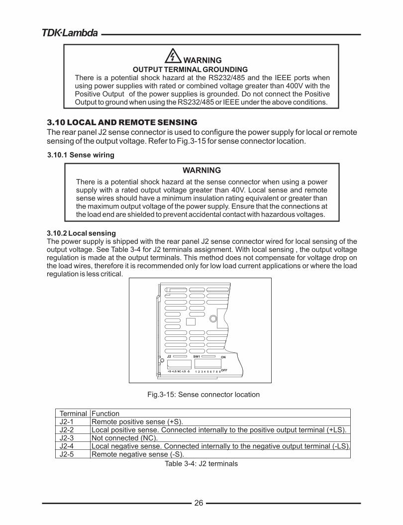
26
26
WARNING
OUTPUT TERMINAL GROUNDING
There is a potential shock hazard at the RS232/485 and the IEEE ports when
using power supplies with rated or combined voltage greater than 400V with the
Positive Output of the power supplies is grounded. Do not connect the Positive
Output to ground when using the RS232/485 or IEEE under the above conditions.
3.10 LOCAL AND REMOTE SENSING
The rear panel J2 sense connector is used to configure the power supply for local or remote
sensing of the output voltage. Refer to Fig.3-15 for sense connector location.
WARNING
There is a potential shock hazard at the sense connector when using a power
supply with a rated output voltage greater than 40V. Local sense and remote
sense wires should have a minimum insulation rating equivalent or greater than
the maximum output voltage of the power supply. Ensure that the connections at
the load end are shielded to prevent accidental contact with hazardous voltages.
3.10.2 Local sensing
The power supply is shipped with the rear panel J2 sense connector wired for local sensing of the
output voltage. See Table 3-4 for J2 terminals assignment. With local sensing , the output voltage
regulation is made at the output terminals. This method does not compensate for voltage drop on
the load wires, therefore it is recommended only for low load current applications or where the load
regulation is less critical.
3.10.1 Sense wiring
Table 3-4: J2 terminals
Fig.3-15: Sense connector location
Function
Remote positive sense (+S).
Local positive sense. Connected internally to the positive output terminal (+LS).
Not connected (NC).
Local negative sense. Connected internally to the negative output terminal (-LS).
Remote negative sense (-S).
Terminal
J2-1
J2-2
J2-3
J2-4
J2-5
+S +LS NC -LS -S 1 2 3 4 5 6 7 8 9
J2
OFF
ONSW1

27
27
WARNING
There is a potential shock hazard at the sense point when using power supply
with a rated output voltage greater than 40V. Ensure that the connections at the
load end are shielded to prevent accidental contact with hazardous voltages.
CAUTION
When using shielded sense wires, ground the shield
in one place only. The location can be the power
supply chassis or one of the output terminals.
3.10.3 Remote sensing
Use remote sense where the load regulation at the load end is critical. In remote sense, the power
supply will compensate for voltage drop on the load wires. Refer to the power supply specifications
for the maximum voltage drop on load wires. The voltage drop is subtracted from the total voltage
available at the output. Follow the instructions below to configure the power supply for remote
sensing:
1. Ensure that the AC On/Off is in the Off position.
2. Remove the local sense jumpers from J2.
3. Connect the negative sense lead to terminal J2-5 (-S) and the positive sense lead to terminal
J2-1(+S) of the J2 mating connector. Ensure that the J2 mating connector is plugged securely
into the rear panel sense connector, J2.
4. Turn On the power supply.
1. If the power supply is operating in remote sense and either the positive or negative load
wire is not connected, an internal protection circuit will activate and shut down the power
supply. To resume operation, turn the AC On/Off to the Off position, connect the open load
wire, and turn On the power supply.
2. If the power supply is operated without the remote sense lines or local sense jumpers, it will
continue to work, but the output voltage regulation will be degraded. Also, the OVP circuit may
activate and shut down the power supply.
- J2 connector type: MC 1.5/5-G-3.81, Phoenix.
- Plug type: MC 1.5/5-ST-3.81, Phoenix.
- Wire AWG; 28 up to 16.
- Stripping length: 7mm.
- Tightening torque:1.95-2.21Lb-Inch. (
To ensure safe transportation of the instrument, contact the Lambda sales or service facility near
you for Return Authorization and shipping information. Please attach a tag to the power supply
describing the problem and specifying the owner, model number and serial number of the power
supply. Refer to Warranty Information for further instructions.
Notes:
3.10.4 J2 sense connector technical information
3.11 REPACKAGING FOR SHIPMENT
0.22- 0.25Nm)

28
VOLTAGE
ALARM FINE PREV/
OVP
UVL FOLD REM/LOC OUT
DC AMPS CURRENT
''
''' '''
DC VOLTS
1 2 3 4 5 6
18 1417 15 16 13 1011 129 7 819
POWER
CHAPTER 4 FRONT AND REAR PANEL CONTROLS
AND CONNECTORS
4.1 INTRODUCTION
4.2 FRONT PANEL CONTROLS AND INDICATORS
The Genesys Power Supply series has a full set of controls, indicators and connectors that allow
the user to easily setup and operate the unit. Before starting to operate the unit, please read the
following sections for explanation of the functions of the controls and connectors terminals.
- Section 4.2: Front panel controls and indicators.
- Section 4.3: Rear panel controls and connectors.
See Fig.4-1 to review the controls, indicators and meters located on the power supply front panel.
TM
28
1
Number Control/Indicator Description Section
High resolution rotary encoder for adjusting the Output
Voltage. Also adjusts the OVP/UVL levels and selects
theAddress.
VOLTAGE control
VOLTAGE indicatorGreen LED , lights for Constant-Voltage mode
operation.2
3 VOLTAGE display
4 digit, 7-segment LED display. Normally displays the
output voltage. When the PREV button is pressed, the
display indicates the programmed setting of the output
voltage. When the OVP/UVL button is pressed, the
Voltage display indicates the OVP/UVLsetting.
Table 4-1: Front Panel controls and indicators
5.2.1
5.3.1
5.4.1
7.2.2
Fig.4-1: Front panel controls and indicators

29
4
Number Control/Indicator Description Section
4 digit, 7-segment LED display. Normally displays the
output current. When the PREV button is pressed, the
display indicates the programmed setting of output
current.
CURRENT display
6 CURRENT control
High resolution rotary encoder for adjusting the Output
Current. Also selects the Baud-Rate of the
communication port.
Table 4-1: Front Panel controls and indicators
5 CURRENT indicator Green LED, lights for Constant-Current mode operation.
Main function
Auxiliary function
: Output ON/OFF control. Press OUT to
set the output On or Off. Press to reset and turn On the
output after OVP or FOLD alarm events have occurred.
: Selects between "Safe-Start" and
"Auto-Restart" modes. Press and hold OUT button to
toggle between "Safe-Start" and "Auto-Restart".The
VOLT display will cycle between "SAF" and "AU7”.
Releasing the OUT button while one of the modes is
displayed, selects that mode.
OUT button
OUT indicator
29
Green LED, lights when Foldback protection is On.
Over Voltage Protection and Under Voltage limit setting.
- Press once to set OVP using VOLTAGE encoder ( the
current display shows “OUP” )
- Press again to set the UVLusing VOLTAGE encoder
( the current display shows “UUL” ).
Main function
Auxiliary function
: Go to local. Press REM/LOC to put the
unit into Local (REM/LOC button is disabled at Local
Lockout mode).
: Address and Baud Rate setting.
Press and hold REM/LOC for 3sec. to set the Address
with the VOLTAGE encoder and the Baud Rate with the
CURRENT encoder.
Green LED, lights when the unit is in Remote mode.
Foldback protection control.
- Press FOLD to set Foldback protection to On.
- To release Foldback alarm event, press OUT to
enable the output and re-arm the protection.
- Press FOLD again to cancel the Foldback protection.
Main function
Auxiliary function
: Press PREV to display the output
voltage and current limit setting. For 5 sec. the display
will show the setting and then it will return to show the
actual output voltage and current.
: Front Panel Lock. Press and hold
PREV button to toggle between “Locked front panel”
and “Unlocked front panel”. The display will cycle
between “LFP” and “UFP”. Releasing the PREV button
while one of the modes is displayed, selects that mode.
REM/LOC button
REM/LOC indicator
FOLD button
FOLD indicator
OVP/UVL button
PREV/ button
Green LED, lights when the DC output is enabled.
7
8
9
10
11
12
13
14
5.2.2
7.2.4
5.6
7.2.5
5.11
7.2.2
7.2.4
5.5
5.3
5.4
5.17

30
30
16
Number Control/Indicator Description Section
FINE button
18 ALARM indicator
Table 4-1: Front Panel controls and indicators
17 FINE indicator
AC Power switch19
Voltage and Current Fine/Coarse adjustment control.
Operates as a toggle switch. In Fine mode, the
VOLTAGE and CURRENT encoders operate with high
resolution and in Coarse mode with lower resolution
(approx. 6 turns).
: Advanced Parallel Operation
Mode setting.
Auxiliary function
Green LED, lights when the unit is in Fine mode.
Red LED, blinks in case of fault detection. OVP, OTP
Foldback, Enable and AC fail detection will cause the
ALARM LED to blink.
AC On/Off control.
4.3 REAR PANEL
See Fig.4-2 to review the connections and controls located on the power supply rear panel.
Refer to Table 4-2 for explanations about the rear panel connections and controls.
Fig.4-2: Rear panel connections and controls
1
Number Item Description Section
AC input
connector
2 DC output
Table 4-2: Rear panel connections and controls
3
Header with a screw plug connector (Phoenix Contact
PC6-16/4-GF-10,16)3.7
Bus-bars for 8V to 100V models.
Wire clamp connector for 150V to 600V models (shown).
3.9.6
RJ-45 type connector, use for connecting power supplies to
RS232 or RS485 port of computer for remote control purposes.
When using several power supplies in a power system, the first
unit Remote-In is connected to the computer and the remaining
units are chained, Remote-In to Remote-Out.
Remote-In
connector7.3
7.4
Green LED, lights when PREV button is pressed.PREV indicator15
1089
AC INPUT
1
J2 ON
OFFOUT IN
J3
J1SW1
57 346 2
8~10V Models 16~100V Models
150~600V
Models (shown)
5.15.2

31
31
Table 4-2: Rear panel connections and controls
RJ-45 type connector, used for chaining power supplies to form
a serial communication bus.
Connector for remote analog interface. Includes output voltage and
current limit programming and monitoring signals, Shut-off control
(electrical signal), Enable/Disable control (dry-contact), power
supply ok (PS_OK) signal and operation mode (CV/CC) signal.
Nine position DIP switch for selecting remote programming and
monitoring modes for Output Voltage, Current Limit and other
control functions.
Blank sub-plate for standard units. Isolated Remote Analog
programming connector for units equipped with Isolated
Analog control option (shown). IEEE connector for units
equipped with IEEE programming option.
M4 stud and hardware for chassis ground connection.
Two position DIP switch for selecting IEEE mode or RS232/485
mode when IEEE option is installed.
Number Item Description Section
4.5
Connector for making remote sensing connections to the load
for regulation of the load voltage and compensation of load
wire drop.
4.4
4.4.1
4.4.2
3.8.2
3.10.2
3.10.3
4
5
6
7
8
10
9
Remote Out
connector
Programming
and
Monitoring
connector
SW1 Setup
switch
Remote
sense
connector
Blank
Sub-plate
Ground
stud
IEEE
switch
7.3
7.4
4.4 REAR PANEL SW1 SETUP SWITCH
The SW1 Setup switch (see Fig.4-3) is a 9-position DIP switch that allows the user to choose the
following:
- Internal or remote programming for Output Voltage and Current Limit.
- Remote voltage or resistive programming of Output Voltage and Output Current limit.
- Select range of remote voltage and resistive programming.
- Select range of Output Voltage and Output Current monitoring.
- Select the Remote Shut-Off control logic.
- Select between RS232 or RS485 communication interface.
- Enable or disable the rear panel Enable/Disable control (dry contact).
Fig.4-3: SW1 setup DIP switch
12
34
56
78
9

32
32
4.4.2 Resetting the SW1 switch
Before making any changes to the SW1 switch setting, disable the power supply output by
pressing the front panel OUT button. Ensure that the output voltage falls to zero and OUT LED is
off, then use any small flat-bladed screwdriver to change the SW1 switch setting.
4.4.1 SW1 position functions
Refer to Table 4-3 for description of SW1 position functions. The factory default setting is Down
for all positions.
Table 4-3: SW1 positions functions
Position Function
SW1-1
SW1-2
SW1-3
Output Voltage
Remote analog programming
Output Current Limit
Remote analog programming
Programming range select
(Remote voltage/resistive)
Output Voltage and
Current Monitoring range
Shut Off logic select
RS232/485 select
Output Voltage
Resistive programming
Output Current Limit
Resistive programming
Enable/Disable control
Up
Output Voltage
Programmed by remote analog
External Voltage or Extenal Resistor
Output Current Limit
Programmed by remote analog
External Voltage or External Resistor
0-10V / (0-10Kohm)
0-10V
On: High (2-15V) or Open
Off: Low (0-0.6V) or Short
RS485 interface
Output Voltage
Programmed by
External Resistor
Output Current Limit
Programmed by
External Resistor
Rear panel
Enable/Disable control is
active
Down (Factory default)
Output Voltage
Programmed by
Front Panel
Output Current Limit
Programmed by
Front Panel
0-5V / (0-5Kohm)
0-5V
On: Low (0-0.6V) or Short
Off: High (2-15V) or Open
RS232 interface
Output Voltage
Programmed by
External Voltage
Output Current Limit
Programmed by
External Voltage
Rear panel
Enable/Disable control is
not active
SW1-4
SW1-5
SW1-6
SW1-7
SW1-8
SW1-9

33
33
4.5 REAR PANEL J1 PROGRAMMING AND MONITORING CONNECTOR
The J1 Programming and Monitoring connector is a DB25 subminiature connector located on the
power supply rear panel. Refer to Table 4-4 for description of the connector functions. The power
supply default configuration is Local operation which does not require connections to J1. For remote
operation using J1 signals use the plug provided with power supply or equivalent type. It is essential
to use plastic body plug to conform with Safety Agency requirements. If a shield is required for J1
wires, connect the shield to a power supply chassis ground screw.
- J1 connector type:AMP, P/N: 5747461-3
- J1 plug description:AMP, P/N: 745211-7
- Wire dimension range:AWG26-22
- Extraction tool:AMP, 91232-1 or equivalent.
- Manual Pistol grip tool:
Handle:AMP, P/N: 58074-1
Head:AMP, P/N: 58063-2
Before making any connection, turn the AC On/Off switch to the Off position and wait until the front
panel display has turned Off.
4.5.1 Making J1 connections
To prevent ground loops and to maintain the isolation of the
power supply when programming from J1, use an
ungrounded programming source.
CAUTION
The programming return terminals (12, 22 and 23) are
referenced internally to the -V potential of the power supply.
Do not attempt to bias any of these terminals relative to the
-V or any other potential. Use the Isolated Programming
interface option to allow control from a programming source
at a different potential relative to the power supply negative
output.
CAUTION
There is a potential shock hazard at the output when using a
power supply with rated output greater than 40V. Use wires
with minimum insulation rating equivalent to the maximum
output voltage of the power supply.
WARNING

34
35
35
CHAPTER 5 LOCAL OPERATION
5.1 INTRODUCTION
5.2 STANDARD OPERATION
This Chapter describes the operating modes that are not involved in programming and monitoring
the power supply via its serial communication port (RS232/RS485) or by remote analog signals.
Ensure that the REM/LOC LED on the front panel is Off, indicating Local mode. If the REM/LOC
LED is On, press the front panel REM/LOC button to change the operating mode to local.
- For information regarding remote analog programming refer to Chapter 6.
- For information regarding usage of the serial communication port refer to Chapter 7.
The power supply has two basic operating modes: Constant Voltage Mode and Constant Current
Mode. The mode in which the power supply operates at any given time depends on the output
voltage setting, output current limit setting and the load resistance.
1. In constant voltage mode, the power supply regulates the output voltage at the selected value,
while the load current varies as required by the load.
2. While the power supply operates in constant voltage mode, the VOLTAGE LED on the front panel
illuminates.
3.Adjustment of the output voltage can be made when the power supply output is enabled
(Output On) or disabled (Output Off). When the output is enabled, simply rotate the VOLTAGE
encoder knob to program the output voltage. When the output is disabled, press the PREV
button and then rotate the VOLTAGE encoder knob. The VOLTAGE meter will show the
programmed output voltage for 5 seconds after the adjustment has been completed. Then the
VOLTAGE meter will display "OFF".
4.Adjustment resolution can be set to coarse or fine resolution.
Press FINE button to select between the lower and higher resolution. The FINE LED turns On
when the resolution is set to FINE.
5.2.1 Constant Voltage Mode
If after completing the adjustment, the display shows a different value
than the setting, the power supply may be at current limit. Check the
load condition and the power supply current limit setting.
The maximum and minimum setting values of the output voltage are
limited by the Over Voltage protection and Under Voltage limit setting.
Refer to Sec.5.3 and 5.4 for more details.
NOTE
NOTE
5.2.2 Constant Current Operation
1. In constant current mode, the power supply regulates the output current at the selected value,
while the voltage varies with the load requirement.
2. While the power supply is operating in constant current mode, the CURRENT LED on the front
panel illuminates.
3.Adjustment of the output current limit can be made when the power supply output is enabled
(Output On) or disabled (Output Off).
- Disabled output (Off): Press PREV button and then rotate the Current encoder knob. The
CURRENT meter will show the programmed current limit for 5 seconds after the adjustment
has been completed. Then the VOLTAGE meter will display "OFF".

36
36
- Enabled output, power supply in Constant Voltage mode: Press the PREV button and then
rotate the CURRENT encoder knob. The CURRENT meter will show the programmed
current limit for 5 seconds after the adjustment has been completed, and then will return to
show the actual load current.
- Enabled output, power supply in Constant Current mode: Rotate the CURRENT encoder
knob to adjust the current limit.
4. Adjustment resolution can be set to Coarse or Fine adjustment. Press the FINE button to
select between the Coarse and Fine resolution. The FINE LED turns On when the resolution
is set to FINE.
If the power supply operates in Constant Voltage mode, while the load current is increased to greater
than the current limit setting, the power supply will automatically switch to Constant Current mode. If
the load is decreased to less than the current limit setting, the power supply will automatically switch
back to Constant Voltage mode.
The OVP circuit protects the load in the event of a remote or local programming error or a power
supply failure. The protection circuit monitors the voltage at the power supply sense points and thus
providing the protection level at the load. Upon detection of an Over Voltage condition, the power
supply output will shut down.
The OVP can be set when the power supply output is Enabled (On) or Disabled (Off). To set the OVP
level, press the OVP/UVLbutton, so that the CURRENT meter shows "OUP".
The VOLTAGE meter shows the OVP setting level. Rotate the VOLTAGE encoder knob to adjust the
OVP level. The display will show "OUP" and the setting value for 5 seconds after the adjustment has
been completed and then will return to it's previous state.
The minimum setting level is approx. 105% of the set output voltage, or the value in Table 7-6,
whichever is higher. The maximum setting level is shown in Table 5-1.
5.2.3 Automatic Crossover
5.3.1 Setting the OVP level
5.3 OVER VOLTAGE PROTECTION (OVP)
Table 5-1: Maximum OVP setting levels
5.3.2 Activated OVP protection indications
5.3.3 Resetting the OVP circuit
When the OVP is activated the power supply output shuts down. The VOLTAGE display shows
"OUP" and theALARM LED blinks.
To reset the OVP circuit after it activates:
1. Reduce the power supply Output Voltage setting below the OVP set level.
2. Ensure that the load and the sense wiring is connected properly.
3. There are four methods to reset the OVP circuit.
3.1 Press OUT button.
3.2 Turn the power supply Off using theAC On/Off switch, wait until the front panel display turns
Off, then turn the power supply On using theAC On/Off switch.
3.3 Turn the power supply output Off and then On using the SO control (refer to sect.5.7). In this
method the power supply should be set toAuto-Restart mode.
3.4 Send OUT1 command via the RS232/485 communication port.
80V100V150V200V300V400V500V600V
88.0V110.0V165.0V220.0V330.0V440.0V550.0V660.0V
ModelMax.
OVP
8V10V16V20V30V40V60V
10.0V12.0V18.0V24.0V36.0V44.0V66.0V
ModelMax.
OVPTo preview the OVP setting, press OVP/UVL
pushbutton so that the CURRENT display will show
"OUP".At this time, the VOLTAGE display will show the
OVP setting. After 5 seconds, the display will return to
it's previous state.

37
5.4 UNDER VOLTAGE LIMIT (UVL)
5.5 FOLDBACK PROTECTION
5.6 OUTPUT ON/OFF CONTROL
5.7 OUTPUT SHUT-OFF (SO) CONTROL VIA REAR PANEL J1 CONNECTOR
The UVL prevents adjustment of the output voltage below a certain limit.The combination of UVL
and OVP functions, allow the user to create a protection window for sensitive load circuitry.
Setting the UVLcan be made when the power supply output is Enabled (On) or Disabled (Off). To set
the UVL level, press the OVP/UVL button TWICE, so that the CURRENT meter shows “UUL”. The
VOLTAGE meter shows the UVL setting level. Rotate the VOLTAGE encoder knob to adjust the UVL
level. The display will show “UUL” and the setting value for 5 seconds after the adjustment has been
completed and then will return to it’s previous state.
UVL setting values are limited at the maximum level to approximately 95% of the Output Voltage
setting. Attempting to adjust the UVL above this limit will result in no response to the adjustment
attempt. The minimum UVLsetting is zero.
5.4.1 Setting the UVL level
Foldback protection will shut down the power supply output if the load current exceeds the current limit
setting level. This protection is useful when the load circuitry is sensitive to an over current condition.
To arm the Foldback protection, the FOLD button should be pressed so that the FOLD LED illuminates.
In this condition, transition from Constant Voltage to Constant Current mode will activate the Foldback
protection.Activation of the Foldback protection disables the power supply output, causes theALARM
LED to blink and display " Fb" on the VOLTAGE meter.
There are four methods to reset an activated Foldback protection.
1. Press the OUT button. The power supply output is enabled and the Output Voltage and current
will return to their last setting. In this method, the Foldback protection remains armed, therefore if
the load current is higher than the current limit setting, the Foldback protection will be activated
again.
2. Press the FOLD button to cancel the Foldback protection. The power supply output will be disabled
and the VOLTAGE display will show “OFF”. Press the OUT button to enable the power supply output.
3. Turn the power supply output Off and then On using the SO control (refer to sect. 5.7). In this method
the foldback protection remains armed, therefore if the load current is higher than the current limit
setting the Foldback protection will be activated.
4. Turn the power supply Off using theAC On/Off switch, wait until the front panel display turns Off,
then turn the unit back ON again. The power supply output is enabled and the Output Voltage and
Current will return to their last setting. In this method, the Foldback protection remains armed,
therefore if the load current is higher than the current limit setting, the Foldback protection will be
activated again.
The Output On/Off enables or disables the power supply output. Use this function to make adjustments
to either the power supply or the load without shutting off the AC power. The Output On/Off can be
activated from the front panel using the OUT button or from the rear panel J1 connector.The OUT
button can be pressed at any time to enable or disable the power supply output. When the output is
disabled, the output voltage and current fall to zero and the VOLTAGE display shows “OFF”.
Contacts 2,3 and 15 of J1 (Fig.4-2, Item 5) serve as Output Shut-Off (SO) terminals. The SO terminals
accept a 2.5V to 15V signal or Open-Short contact to disable or enable the power supply output. The
SO function will be activated only when a transition from On to Off is detected after applying AC power
to unit. (Thus , inAuto-Restart mode, the output will be enabled after applyingAC power, even if SO is in
Off level.). After On to Off transition is detected, the SO will enable or disable the power supply output
according to the signal level or the short/open applied to J1. This function is useful for connecting power
supplies in a “Daisy-chain” (refer to section 5.16). The SO control can be used also to reset the OVP
and Fold Protection. Refer to sect. 5.3 and 5.5 for details.
5.5.1 Setting the Foldback protection
5.5.2 Resetting activated Foldback protection
37

38
When the unit is shut-off by J1 signal, the VOLTAGE display will show “SO” to indicate the unit state. J1
contact 15 is the SO signal input and contacts 2 and 3, IF_COM, are the signal return (connected
internally). Contacts 2,3 and 15 are optically isolated from the power supply output.
The SO control logic can be selected by the rear panel SW1 Setup switch. Refer to Table 5-2 for SW1
setting and SO control logic.
Table 5-2: SO logic selection
SW1-5 setting
Down (default)
Up
SO signal level
J1-2(3), 15
2-15V or Open
0-0.6V or Short
2-15V or Open
0-0.6V or Short
Power supply
output
On
Off
Off
On
Display
Voltage/Current
“SO”
“SO”
Voltage/Current
5.8 ENABLE/DISABLE CONTROL VIA REAR PANEL J1 CONNECTOR
Contacts 1 and 14 of J1 (Fig.4-2, Item 5) serve as Output Enable/Disable terminals by switch or relay.
This function is enabled or disabled by the SW1 Setup switch position 9. Refer to Table 5-3 for
Enable/Disable function and SW1 setting.
Table 5-3: Enable/Disable function and SW1 setting
SW1-9 setting
Down (Default)
Enable/Disable inputs
Open or Short
Open
Short
Power supply output
On
Off
On
Display
Voltage/Current
“ENA”
Voltage/Current
ALARM LED
Off
Blinking
OffUp
5.9 CV/CC SIGNAL
5.10 PS_OK SIGNAL
CV/CC signal indicates the operating mode of the power supply, Constant Voltage or Constant Current.
CV/CC signal is an open collector output with a 30V parallel zener, at J1-13, referenced to the COM
potential at J1-12 (connected internally to the negative sense potential). When the power supply
operates in Constant Voltage mode, CV/CC output is open. When the power supply operates in Constant
Current mode, CV/CC signal output is low(0-0.6), with maximum 10mAsink current.
PS_OK signal indicates fault condition in the power supply. PS_OK is a TTL signal output at J1-16,
referenced to IF_COM at J1-2,3 (Isolated Interface Common)). When a fault condition occurs, PS_OK
level is low, with maximum sink current of 1mA, when no fault condition occurs, PS_OK level is high with
maximum source current of 2mA. The following faults will set the PS_OK to Fault state:
38
Safe Start mode
Auto Restart mode
-If the Enable/Disable fault condition clears when units in safe start mode
recovery is by pressing OUT button or by sending a ‘OUT 1’serial command.
- The output will return back ON automatically when the Enable/Disable
fault conditions clears.
To prevent possible damage to the unit, do not connect any of the
Enable/Disable inputs to the positive or negative output potential.
CAUTION
Do not connect CV/CC signal to a voltage source higher than 30VDC.
Always connect CV/CC signal to the voltage source with a series resistor
to limit the sink current to less than 10mA.
CAUTION
*OTP
*OVP
*Foldback
*AC fail
*Enable/Disable open (Power supply is disabled)
*SO (Rear panel Shut-Off - Power supply is shut off))
*IEEE failure (with optional IEEE interface)
*Output Off
NOTE

39
39
5.11 SAFE START AND AUTO-RESTART MODES
5.12 OVER TEMPERATURE PROTECTION (OTP)
5.13 LAST SETTING MEMOR
5.14 SERIES OPERATION
When turning on the power supply AC On/Off, it can start to its last setting of Output Voltage and
Current limit with the output enabled (Auto-restart) or start with the output disabled (Safe mode).
Press and hold the OUT button to select between Safe start andAuto-restart modes. The VOLTAGE
display will continuously cycle between "SAF" and "AU7” every 3 seconds. Releasing OUT
pushbutton while one of the modes is displayed, selects that mode. The default setting at shipment
is Safe mode.
In this mode, the power supply restores its last operation setting. Upon start-up, the output is
enabled or disabled according to its last setting.
In this mode, the power supply restores its last operation setting and sets the Output to Off state. At
start-up, the output is disabled and the output voltage and current are zero. To enable the output and
restore the last output voltage and current limit values, momentarily press OUT button.
The OTP circuit shuts down the power supply before the internal components can exceed their safe
internal operating temperature. When an OTP shutdown occurs, the display shows "O7P" and the
ALARM LED blinks.
Resetting the OTP circuit can be automatic (non-latched) or manual (latched) depending on the
Safe orAutomatic restart mode.
In Safe start mode, the power supply stays off after the over temperature
condition has been removed. The display continue to shows "O7P" and theALARM LED
continues to blink. To reset the OTP circuit, press OUT button (or send OUT ON command via the
serial port).
InAuto-restart mode , the power supply recovers to it's last setting
automatically when the over temperature condition is removed.
The power supply is equipped with Last Setting Memory, which stores power supply parameters at
eachAC turn-off sequence.
1. OUT On or Off
2. Output voltage setting (PV setting)
3. Output current limit (PC setting)
4. OVP setting
5. UVLsetting
6. FOLD setting
7. Start-up mode (Safe orAuto-restart)
8. Remote/Local:If the last setting was Local Lockout (latched mode), the supply will return to
Remote mode (non-latched).
9.Address setting
10. Baud rate
11. Locked /Unlocked front panel (LFP/UFP)
(Items 8, 9, 10 are related to Remote digital control operation and explained in chapter 7)
12. Master/Slave setting
Power supplies of the SAME MODEL can be connected in series to obtain increased output voltage.
Split connection of the power supplies gives positive and negative output voltage.
5.11.1Automatic start mode
5.11.2 Safe start mode
1. Safe start mode:
2.Auto-restart mode:
Y
STORED PARAMETERS:

40
40
Do not connect power supplies from different
manufacturers in series or in parallel.
CAUTION
When power supplies are connected in series, and
the load or one of the output terminals is grounded,
no point may be at a greater potential of +/-60VDC
from ground for models up to 60VDC Rated Output
and +/-600VDC from ground for models >60VDC
Rated Output. When using RS232/485 or IEEE, refer
to the OUTPUT TERMINALS GROUNDING
warning, section 3.9.11.
5.14.1 Series connection for increased output voltage
In this mode, two units are connected so that their outputs are summed. Set the current limit of
each power supply to the maximum that the load can handle without damage. It is
recommended that diodes be connected in parallel with each unit output to prevent reverse
voltage during start up sequence or in case one of the units shuts down. Each diode should be
rated to at least the power supply rated output voltage and output current. Refer to Fig.5-1 and
5-2 for series operation with local and remote sensing.
+S
+
-
-S-LS
+LS
POWER
SUPPLY
+S
+
+
-
-
-S-LS
+LS
POWER
SUPPLY
LOAD
+S
+
-
-S-LS
+LS
POWER
SUPPLY
+S
+
+
-
-
-S-LS
+LS
POWER
SUPPLY
LOAD
Fig.5-1: Series connection, local sensing Fig.5-2: Series connection, remote sensing
Remote programming in series operation for increased output voltage:
1.Programming by external voltage:
2.Using the SO function and PS_OK signal:
The analog programming circuits of this power supply
are referenced to the negative output potential.
Therefore, the circuits used to control each series
connected unit must be separated and floated from
each other.
The Shut-Off and PS_OK circuits are referenced to the
isolated interface common, IF_COM (J1-2,3). The
IF_COM terminals of different units can be connected
to obtain a single control circuit for the power supplies
connected in series.
(*)
(*)
(*)
(*)
(*) Diodes are
user supplied.
WARNING

41
41
Fig.5-3: Series connection for positive/negative output voltages
3. Programming by external resistor:
1. Programming by external voltage:
Programming by external resistor is possible . Refer to
section 6-5 for details.
The analog programming circuits of this power supply
are referenced to the negative output potential.
Therefore, the circuits used to control each series
connected unit must be separated and floated from
each other.
The communication port is referenced to the IF_COM
which is isolated from the power supply output
potential. Therefore power supplies connected in
series can be chained using the Remote-In and
Remote-Out connectors. Refer to chapter 7 for details.
The Shut-Off and PS_OK circuits are referenced to the
isolated interface common, IF_COM (J1-2,3). The
IF_COM terminals of the units can be connected to
obtain a single control circuit for the power supplies
connected in series.
4. Programming via the Serial
Communication port (RS232/RS485):
4. Programming via the Serial
Communication port (RS232/RS485):
5.14.2 Series connection for positive and negative output voltage
In this mode, two units are configured as a positive and negative output. Set the current limit of each
power supply to the maximum that the load can handle without damage. It is recommended that
diodes be connected in parallel with each unit output to prevent reverse voltage during start-up or in
case one of the units shuts down. Each diode should be rated to at least the power supply rated
output voltage and output current. Refer to Fig.5-3 for this operating mode.
+S
+
-
-S-LS
+LS
POWER
SUPPLY
+S
+
+
-
-
-S-LS
+LS
POWER
SUPPLY
COM.
Remote programming in series operation for positive and negative output voltage
2. Using the SO function and PS_OK
signal :
3. Programming by external resistor : Programming by external resistor is possible. Refer
to section 6.5 for details.
The communication port is referenced to the IF_COM
which is isolated from the power supply output
potential. Therefore power supplies connected in
series can be chained using the Remote-In and
Remote-Out connectors. Refer to chapter 7 for details.
LOAD
(*)
(*)
(*) Diodes are user supplied.

42
42
5.15 PARALLEL OPERATION
Up to four units of the same VOLTAGE and CURRENT rating can be connected in parallel to provide
up to four times the output current capability. One of the units operates as a master and the
remaining units are slaves. The slave units are analog programmed by the master unit.
In remote digital operation, only the master unit can be programmed by the computer while the slave
units may be connected to the computer for voltage, current and status readback only.
There are two methods, basic and advanced, to configure multiple supplies for parallel operation.
Refer to Sec. 5.15.1 and to Sec. 5.15.2 for detailed explanation.
In this method, setting the units as Master and Slaves is made by the rear panel J1 connections and
the setup switch SW1. Each unit displays its own output current and voltage. To program the load
current, the Master unit should be programmed to the total load current divided by the number of
units in the system. Refer to the following procedure to configure multiple supplies for simple parallel
operation.
5.15.1 Basic parallel operation
5.15.2 Advanced parallel operation
In this method, multiple supplies can be configured to parallel operation as a single power supply.
The total load current and output voltage are displayed by the Master unit and can be readback
from the Master unit. The Slave units display only their operating status (On, Off or Fault
condition).
Refer to the following procedure to configure multiple supplies for Advanced parallel operation.
1. Basic configuration
Repeat steps 1 to 5 in Sec. 5.15.1 (Basic parallel operation).
1. Setting up the Master unit
2. Setting up the slave units
3. Setting Over Voltage protection
4. Setting Foldback protection
5. Connection to the load
Set the master unit output voltage to the desired voltage. Program the current limit to the
desired load current limit divided by the number of parallel units. During operation, the master
unit operates in CV mode, regulating the load voltage at the programmed output voltage.
Connect the sensing circuit to local or remote sensing as shown in Fig.5-4 or Fig.5-5.
-1.The output voltage of the slave units should be programmed 2%~5% higher than the output
voltage of the master unit to prevent interference with the master unit's control.
The current limit of each unit should be programmed to the desired load current limit
divided by the number of parallel units.
-2.Set the rear panel setup switch SW1 position 2 to it's up position.
-3.Set the rear panel setup switch SW1 position 3 in the same position as
SW1 position 4 of the master.
-4.Connect short between J1-8 and J1-12 (refer to Table 4-4.)
-5. Connect J1 terminal 10(IPGM) of the slave unit to J1 terminal 25(P) of the master unit.
-6. Connect J1 terminal 23(IPGM_RTN) of the slave unit to J1 terminal 12(COM) of the master
unit.
During operation the slave units operate as a controlled current source following the master
output current. It is recommended that the power system is designed so that each unit supplies
up to 95% of its current rating because of the imbalance which may be caused by cabling and
connections voltage drop.
The master unit OVP should be programmed to the desired OVP level. The OVP of the slave
units should be programmed to a higher value than the master OVP. When the master unit
shuts down, it programs the slave unit to zero output voltage. If a slave unit shuts down
(when its OVP is set lower than the master output voltage), only that unit would shut down
and the remaining slave units would supply all the load current.
Foldback protection if desired, may only be used with the master unit. When the master unit
shuts down it programs the slave units to zero output voltage.
In parallel operation, power supplies can be connected in local or remote sensing. Refer to
Fig.5-4 and 5-5 for typical connections of parallel power supplies. The figures show
connection of two units, however the same connection method applies up to 4 units.

43
43
+V
-V
+V
-V
+S+LS-S -LS
+S+LS-S -LS
MASTER
POWER SUPPLY
SLAVE#1
POWER SUPPLY
J1-25 J1-12 COM
J1-10 J1-23
P
IPGM IPGM_RTN
To J1-23SLAVE#2
POWER SUPPLY
To J1-10SLAVE#2
POWER SUPPLY
Fig.5-4: Parallel connection
with local sensing
+
-
LOAD
As short as possible
Twistedpair
J1-8 J1-12
CAUTION
Make sure that the connection between -Vo terminals is reliable to avoid disconnection during
operation. Disconnection may cause damage to the power supply.
2. Setting the units as Master or Slave
3. Master and Slave units default operation
4. CURRENT display accuracy
5. To release units from Slave mode
a) Depress and hold the FINE button for 3 seconds. The Master/Slave configuration will be
displayed on the Current Display. Rotate the CURRENT encoder to obtain the desired mode.
Refer to Table 5-4 for the CURRENT display and modes of operation.
b) When the desired configuration is obtained, depress and release the FINE button or wait
approx. 5 seconds.
a) When a unit is programmed to Slave mode it enters the Remote mode with Local Lockout. In
this mode, the front panel controls are disabled to prevent accidental setting change (refer to Sec.
7.2.7 for details).
b) The Slave units parameters will automatically set the following:
*Output voltage to approximate. 102% of rated output voltage.
*Programmed Current to zero.
*UVL to zero volts
*OVP to its maximum value
c) The Master and Slave modes are stored in the power supply EEPROM when the AC power is
Turned off. The system will return to the Master/Slave mode upon re-application of AC power.
In the advanced parallel mode, the total current is programmed and reported by the Master. In
this method, the CURRENT display accuracy is 2%+/- 1 count. In cases that higher accuracy is
required, it is recommended to use the basic parallel operation mode.
Slave units can be released using the following procedure:
a) Depress FINE button for 3 seconds. The Master/Slave configuration will be displayed on the
CURRENT display.
b) Select H1 mode using the CURRENT encoder.
c) Depress FINE button again or wait 5 seconds.
d) Turn the AC power Off to store the new setting.
e) After exiting from Slave operation the unit’s parameters will be set to:
CURRENT Display
H1
H2
H3
H4
S
Operating Mode
Single supply (default)
Master supply with 1 Slave supply
Master supply with 2 Slave supplies
Master supply with 3 Slave supplies
Slave supply
Table 5-4: Setting mode of operation
*AST On
*OUT On
*Foldback protection Off
*Programmed Voltage to zero *AST OFF
*Programmed Current to zero *OUT OFF
*UVL to zero volts *Foldback protection OFF
*OVP to its maximum value *Locked Front Panel

44
44
Fig.5-5: Parallel operation
wiith Remote sensing
With local sensing it is important to minimize the wire length and resistance. Also the
positive and negative wire resistance should be close as possible to each other to achieve
current balance between power supplies.
NOTE
NOTE
5.16 DAISY-CHAIN CONNECTION
It is possible to configure a multiple power supply system to shut down all the units when a fault
condition occurs in one of the units. When the fault is removed, the system recovers according to its
setting to Safe start mode orAutomatic restart.
Setup switch SW1 position 5 should be set to its Down position to enable the Daisy-chain operation.
Other SW1 positions can be set according to the application requirements.
If a fault occurs in one of the units its PS_OK signal will be set to low level and the display will indicate
the fault. The other units will shut off and their display will indicate "SO”. When the fault condition is
removed, the units will recover to their last setting according to their Safe start orAuto-restart setting.
Fig.5-6 shows connection of three units, however the same connection method applies to systems
with a larger number of units.
Fig.5-6: Daisy-chain connection
POWER SUPPLY
#1
J1-2,3 J1-16 J1-16J1-16J1-15
PS_OK
POWER SUPPLY
#2
J1-2,3 J1-15
PS_OK SO
POWER SUPPLY
#3
J1-2,3 J1-15
PS_OK SOSOIF_COM IF_COM IF_COM
5.17 FRONT PANEL LOCKING
The front panel controls can be locked to protect from accidental power supply parameter change.
Press and hold PREV button to toggle between “Locked front panel” and “Unlocked front panel”.
The display will cycle between “LFP” and “UFP”. Releasing the PREV button while one of the
modes is displayed, selects that mode.
In this mode, the front panel controls are enable to program and monitor the power supply
parameters.
In this mode the following front panel controls are disabled:
- VOLTAGE and CURRENT encoders.
- FOLD button.
- OUT button.
The power supply will not respond to attempts to use these controls. The VOLT display will show
“LFP” to indicate that the front panel is locked.
OVP/UVLbutton is active to preview the OVP and UVLsetting.
Use PREV button to preview the output voltage and current setting or to unlock the front panel.
5.17.1 Unlocked front panel
5.17.2 Locked front panel
MASTER
POWER SUPPLY
SLAVE#1
POWER SUPPLY
J1-25
J1-10
P
IPGM
J1-12 COM
J1-23
IPGM_RTN
Twistedpair
+V
-V
+V
-V
+S
-S
+
-
LOAD
As short as possible
Twistedpair
+S-S
+S
-S
Twistedpair
+S-S
+S
-S
J1-8 J1-12
To J1-10SLAVE#2
POWER SUPPLY
To J1-23SLAVE#2
POWER SUPPLY
CAUTION
Make sure that the
connection between -Vo
terminals is reliable to
avoid disconnection
during operation.
Disconnection may cause
damage to the power
supply.
1.In parallel operation, the AC Supply should be applied to the Master Unit first and then to the
Slave unit.
2.The above sequence is not required if the units are connected in daisy-chain.
NOTE

45
45
CHAPTER 6 REMOTE ANALOG PROGRAMMING
6.1 INTRODUCTION
The rear panel connector J1 allows the user to program the power supply output voltage and current
limit with an analog device. J1 also provides monitoring signals for output voltage and output current.
The programming range and monitoring signals range can be selected between 0-5V or 0-10V
using the setup switch SW1. When the power supply is in Remote Analog programming, the serial
communication port is active and can be used to read the power supply parameters.
CAUTION
COM (J1-12), VPGM_RTN (J1-22) and IPGM_ RTN (J1-23) terminals of J1
are referenced to the -Vout potential (-V). Do not connect these terminals to
any potential other than -Vout (-V), as it may damage the power supply.
6.2 LOCAL /REMOTE ANALOG CONTROL
Contact 8 of J1 (Fig. 4-2, item 5) accepts TTL signal or Open-Short contact (referenced to J1-12) to
select between Local or RemoteAnalog programming of the output voltage and current limit.
In Local mode, the output voltage and current limit can be programmed via the front panel VOLTAGE
and CURRENT encoders or via the RS232/485 port. In Remote Analog mode, the output voltage
and current limit can be programmed by analog voltage or by programming resistors via J1 contacts
9 and 10 (refer to sec. 6.4 and 6.5). Refer to Table 6-1 for Local/Remote Analog control (J1-8)
function and Setup switch SW1-1, 2 setting.
6.3 LOCAL/REMOTE ANALOG INDICATION
Contact 21 of J1 (Fig. 4-2, item 5) is an open collector output that indicates if the power supply is in
Local mode or in Remote Analog mode. To use this output, connect a pull-up resistor to a voltage
source of 30Vdc maximum. Choose the pull-up resistor so that the sink current will be less than 5mA
when the output is in low state. Refer to Table 6-2 for J1-21 function.
Table 6-1: Local/Remote Analog control function
Table 6-2: Local/Remote Analog indication
SW1-1,2 setting
Down (default)
Up
J1-8 functionOutput voltage/
Current setting
No effect
"0" or Short
"1" or Open
Local
Remote Analog
Local
TTL "0" or short
TTL "1" or open
SW1-1 SW1-2J1-8 J1-21 signal
Down
Down
Up
Up
Down or Up
Down
Up
Down
Up
Down or Up
Open
0~0.6V
0~0.6V
0~0.6V
Open

46
46
CAUTION
To maintain the isolation of power supply and prevent ground loops, use an
isolated programming source when operating the power supply via remote
analog programming at J1 connector.
6.4 REMOTE VOLTAGE PROGRAMMING OF OUTPUT VOLTAGE AND CURRENT LIMIT
SW1-3 setting
UP
DOWN
Output Voltage programming
VPGM (J1-9)
0-10V
0-5V
Current limit programming
IPGM (J1-10)
0-10V
0-5V
Table 6-3: SW1-3 setting and programming range
1
14
13
25
1012 89
23 22
+- + -
CURRENT LIMIT
PROGRAMMING
OUTPUT VOLTAGE
PROGRAMMING
J1 connector, rear panel view
Fig.6-1: Remote voltage programming connection
Perform the following procedure to set the power supply to Remote Voltage programming :
1. Turn the power supply AC On/Off switch to Off.
2. Set setup switch SW1-1 to its UP position for output voltage external programming and
SW1-2 to its UP position for Output Current limit external programming.
3. Set SW1 position 3 to select programming voltage range according to Table 6-3.
4. Ensure that SW1 positions 7 and 8 are at their Down (default) position.
5. Connect a short between J1-8 and J1-12 (refer to Table 4-4).
6. Connect the programming source to the mating plug of J1 as shown in Fig.6-1. Observe
correct polarity for the voltage source.
7. Set the programming sources to the desired levels and turn the power supply ON. Adjust the
programming sources to change the power supply output.
1. SW1 positions 4,5,6 and 9 are not required for remote programming. Their setting can be
determined according the application.
2. The control circuits allow the user to set the output voltage and current limit up to 5% over
the model-rated maximum value. The power supply will operate within the extended range,
however it is not recommended to operate the power supply over its voltage and current
rating and performance is not guaranteed.
NOTES:
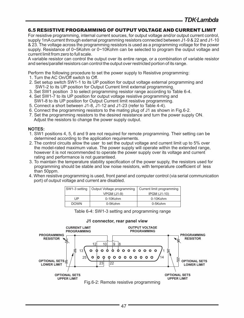
47
6.5 RESISTIVE PROGRAMMING OF OUTPUT VOLTAGE AND CURRENT LIMIT
For resistive programming, internal current sources, for output voltage and/or output current control,
supply 1mAcurrent through external programming resistors connected between J1-9 & 22 and J1-10
& 23. The voltage across the programming resistors is used as a programming voltage for the power
supply. Resistance of 0~5Kohm or 0~10Kohm can be selected to program the output voltage and
current limit from zero to full scale.
A variable resistor can control the output over its entire range, or a combination of variable resistor
and series/parallel resistors can control the output over restricted portion of its range.
Perform the following procedure to set the power supply to Resistive programming:
1. Turn the AC On/Off switch to Off.
2. Set setup switch SW1-1 to its UP position for output voltage external programming and
SW1-2 to its UP position for Output Current limit external programming.
3. Set SW1 position 3 to select programming resistor range according to Table 6-4.
4. Set SW1-7 to its UP position for output voltage resistive programming and
SW1-8 to its UP position for Output Current limit resistive programming.
5. Connect a short between J1-8, J1-12 and J1-23 (refer to Table 4-4).
6. Connect the programming resistors to the mating plug of J1 as shown in Fig.6-2.
7. Set the programming resistors to the desired resistance and turn the power supply ON.
Adjust the resistors to change the power supply output.
1. SW1 positions 4, 5, 6 and 9 are not required for remote programming. Their setting can be
determined according to the application requirements.
2. The control circuits allow the user to set the output voltage and current limit up to 5% over
the model-rated maximum value. The power supply will operate within the extended range,
however it is not recommended to operate the power supply over its voltage and current
rating and performance is not guaranteed.
3. To maintain the temperature stability specification of the power supply, the resistors used for
programming should be stable and low noise resistors, with temperature coefficient of less
than 50ppm.
4. When resistive programming is used, front panel and computer control (via serial communication
port) of output voltage and current are disabled.
NOTES:
SW1-3 setting
UP
DOWN
Output Voltage programming
VPGM (J1-9)
0-10Kohm
0-5Kohm
Current limit programming
IPGM (J1-10)
0-10Kohm
0-5Kohm
Table 6-4: SW1-3 setting and programming range
47
1
14
13
25
10 9
23 22
CURRENT LIMIT
PROGRAMMING
OUTPUT VOLTAGE
PROGRAMMING
J1 connector, rear panel view
Fig.6-2: Remote resistive programming
PROGRAMMING
RESISTOR
PROGRAMMING
RESISTOR
OPTIONAL SETS
LOWER LIMIT
OPTIONAL SETS
LOWER LIMIT
OPTIONAL SETS
UPPER LIMIT
OPTIONAL SETS
UPPER LIMIT
12 8

48
48
6.6 REMOTE MONITORING OF OUTPUT VOLTAGE AND CURRENT
The J1 connector, located on the rear panel provides analog signals for monitoring the output
voltage and output current. Selection of the voltage range between 0-5V or 0-10V is made by
setup switch SW1-4. The monitoring signals represent 0 to 100% of the power supply output
voltage and output current.The monitor outputs have 500 ohm series output resistance. Ensure
that the sensing circuit has an input resistance of greater than 500 Kohm or accuracy will be
reduced.
Refer to Table 6-5 for required J1 connection, SW1-4 setting and monitoring voltage range.
Signal
name
VMON
IMON
VMON
IMON
Signal function
Vout monitor
Iout monitor
Vout monitor
Iout monitor
Signal (+)
J1-11
J1-24
J1-11
J1-24
J1-12
J1-12
0-5V
0-10V
Down
Up
Range SW1-4
Return (-)
J1 connection
Table 6-5 Monitoring signals setting
FCC requirements for radiated emissions, use
shielded cable for the analog control signals. In case of
using unshielded cable, attach an EMI ferrite
suppressor to the cable, as close as possible to the
power supply.
1.Radiated emissions, FCC requirements:
Notes:
2. Front panel encoders operation:
3. Front panel PREV button:
4. Communication:
In Remote analog mode the output voltage and
current can’t be set by the VOLTAGE and CURRENT
encoders.
Use PREV button to display the output voltage and
current setting defined by the encoders or
communication.
In Remote analog mode, power supply parameters
can be programmed and readback via the
communication port except output voltage and current
setting.

49
CHAPTER 7 RS232 & RS485 REMOTE CONTROL
7.1 INTRODUCTION
7.2 CONFIGURATION
This chapter describes the operation of the Genesys 5000W power supplies via the serial
communication port. Details of the initial set-up, operation via RS232 or RS485, the command set
and the communication protocol are described in this chapter.
The power supply is shipped with the following setting:
TM
7.2.1 Default setting
-Address:
-Baud-rate:
-RS232/485:
-Vout setting:
-Iout setting:
-Master/Slave
6
9600
RS232
0
Maximum
H1 (Master)
-Output:
-Start up mode:
-OVP:
-UVL:
-Foldback:
-Front panel:
Off
Safe start
Maximum
0
Off
Unlocked (UFP)
7.2.2 Address setting
7.2.3 RS232 or RS485 selection
7.2.4 Baud rate setting
7.2.5 Setting the unit into Remote or Local mode
The power supply address can be set to any address between 0 and 30. Follow the instructions
described below to set the address.
1. If the unit is in Remote mode (front panel REM/LOC LED illuminates), press REM/LOC
button to put the unit into Local mode.
2. Press and hold for approximately 3sec. the REM/LOC button. The VOLTAGE display will
indicate the communication port address.
3. Using the VOLTAGE adjust encoder, select the address.
To preview the address at any time, press and hold the REM/LOC button for approx. 3sec. The
VOLTAGE display will indicate the power supply address.
To select between RS232 or RS485 set the rear panel setup switch SW1-6 position to:
- Down for RS232
- Up for RS485
Five optional rates are possible: 1200, 2400, 4800, 9600 and 19200. To select the desired rate,
the following steps should be taken:
1. If the unit is in Remote mode (front panel REM/LOC LED illuminates), press REM/LOC
button to put the unit into Local mode.
2. Press and hold for approx. 3sec. the REM/LOC button. The CURRENT display will show
the communication port Baud Rate.
3. Using the CURRENT adjust encoder, select the desired Baud Rate.
1. The unit will be put into Remote mode only via serial communication command.
Commands that will put the unit into Remote mode are:
RST PV n
OUT n PC n
RMT n
(for n values see Tables 7-3, 7-4, 7-5 and 7-6)
49

50
2. There are two Remote modes:
1. Remote:
2. Local Lockout:
In this mode, return to local can be made by the front panel REM/LOC or via
serial port command RMT 0. Set the unit into Remote mode via serial port
RMT 1 command.
In this mode the unit can be returned to Remote mode via the serial port
RMT 1 command or by turning off the AC power until the display turns off
and then turn it to on again. In Local Lockout mode, the front panel
REM/LOC button is not active. Set the unit into Local Lockout mode via
serial port RMT 2 command.
7.2.6 RS232/485 port in Local mode
7.2.7 Front panel in Remote mode
When the power supply is in local mode, it can receive queries or commands. If a query is received,
the power supply will reply and remain in Local mode. If a command that affects the output is
received, the power supply will perform the command and change to Remote mode.
Serial commands may be sent to set the status registers and read them while the unit is in Local
mode. If the Enable registers are set (refer to section 7.8) the power supply will transmit SRQ’s while
in Local.
Front panel control in Remote mode is disabled except for:
1. PREV: use to preview the Voltage and Current limit setting.
2. OVP/UVL: use to preview the OVP/UVLsetting.
3. LOC/REM: use to set the unit into Local mode.
In Local Lockout mode, only PREV and OVP/UVLare active.
The RS232/485 interface is accessible through the rear panel RS232/485 IN and RS485 OUT
connectors. The connectors are 8 contact RJ-45. The IN and OUT connectors are used to connect
power supplies in a RS232 or RS485 chain to a controller. Refer to Fig.7-1 for IN/OUT connectors
7.3 REAR PANEL RS232/485 CONNECTOR
Tx and Rx are used for RS232 communication. Txd +/- and Rxd +/- are used for RS485
communication. Refer to RS232 and RS485 cables description for connection details.
50
NOTE
NC
NC
RX
NC NC
TXD
RXDTXD
RXD
RXD
TXDRXD
TXD
SG
SG
-
--
-+
+
+
+
TX
OUT IN
Fig.7-1: J3 rear panel IN/OUT connectors pinout
8 7 6 5 4 3 2 1 8 7 6 5 4 3 2 1
Shield
(connector enclosure)

51

52
52
7.4.2 Multi power supply connection to RS232 or RS485 bus
Daisy-chain up to 31 units can be connected to RS232 or RS485 bus. The first unit connects to thecontroller via RS232 or RS485 and the other units are connected with RS485 bus, the user must setall slave supplies to a unique address. No two supplies may have the same address.
1. First unit connection: Refer to section 7.4.1 for connecting the first unit to the controller.
2. Other units connection: The other units on the bus are connected via their RS485 interface.
Refer to fig.7-5 for typical connection.
- Set rear panel setup switch SW1-6 to it's UP position
- Using the Linking cable supplied with each unit (refer to Fig.7-6), connect each unit OUT
connector to the next unit IN connector.
* I
120 ohm resistive termination at the last unit’s RS485 OUT connector.
120 W between TXD and TXD������+ -
t is recommended when using ten or more power supplies in Daisy-chain system to connect a
120 W between RXD and RXD������+ -
7.5 COMMUNICATION INTERFACE PROTOCOL
7.5.1 Data format
7.5.2 Addressing
7.5.3 End of Message
7.5.4 Command Repeat
7.5.5 Checksum
7.5.6 Acknowledge
Serial data format is 8 bit, one start bit and one stop bit. No parity bit.
The Address is sent separately from the command.It is recommended to add a 100 msec software delay between query or sent command tonext unit addressing.Refer to section 7.7.3 for details.
The end of message is the Carriage Return character (ASCII 13). The power supply ignores the Line
Feed (ASCII 10) character.
The backslash character “\” will cause the last command to be repeated.
The user may optionally add a checksum to the end of the command. The checksum is "$" followed by
two hex characters. If a command or a query has checksum, the response will also have one. There is no
CR between the command string and the "$" sign.Example: STT?$3A
STAT?$7B
The power supply acknowledges received commands by returning "OK" message. If an error is detected,
the power supply will return an error message. The rules of checksum apply also to the acknowledge.
IN OUT
POWER SUPPLY
#1
IN OUT
POWER SUPPLY
#2
IN OUT
POWER SUPPLY
#3
RS232/485 RS485 RS485 RS485
IN OUT RS485
120 OHM
TERMINATIONPOWER SUPPLY
#31
RS485
Fig7-5: Multi power supplies RS232/485 connection
1
6
3
5
4
1
6
3
5
4
PIN NO.
HOUSING HOUSING
PIN NO.NAME NAME
SHIELD
SG
TXD
TXD
RXD
RXD
SHIELD
SG
RXD
RXD
TXD
TXD
8 PIN CONNECTOR (IN) 8 PIN CONNECTOR (OUT)
-+
+
+
+
-
-
-
Serial link cable with RJ-45 shielded connectors (P/N: GEN/RJ45)Fig.7-6:
8
1
1
8
L=0.5m typ.
The address (ADR n) command must return an “OK” response before
any other commands are accepted.
NOTE

53
53
7.5.7 Error message
7.5.8 Backspace
If an error is detected in a command or query, the power supply will respond with an error
message. Refer to section 7.6 for details.
The backspace character (ASCII 8) clears the last character sent to the power supply.
The power supply will return error messages for illegal commands and illegal programming
parameters. Refer to Table 7-1 for programming error messages and Table 7-2 for commands
error messages.
Table 7-1: Programming error messages
7.6 ERROR MESSAGES
Table 7-2: Commands error messages
7.7 COMMAND SET DESCRIPTION
7.7.1 General guides
7.7.2 Command set categories
1. Any command or argument may be in capital letters or small letters.
2. In commands with an argument, a space must be between the command and the argument.
3. For any command that sets a numeric value, the value may be up to 12 characters long.
4. Carriage Return: If the CR character (ASCII 13) is received by itself, the power supply will
respond with "OK" and CR.
The Genesys 5000W series command set is divided into four categories as follows:
1. Initialization control
2. ID control
3. Output control
4. Status control
TM
E01
E02
E04
E06
E07
Description
Returned when program voltage (PV) is programmed above acceptable range.
Example: PV value is above '105% of supply rating' or 'PV above 95% of OVP setting'.
Returned when programming output voltage below UVLsetting.
Returned when OVP is programmed below acceptable range.
Example:OVP value is less than '5% of supply voltage rating' plus 'voltage setting'.
Returned when UVLvalue is programmed above the programmed output voltage.
Returned when programming the Output to ON during a fault shut down.
Error
Code
C01
C02
C03
C04
C05
Description
Illegal command or query
Missing parameter
Illegal parameter
Checksum error
Setting out of range
Error
Code

54
7.7.3 Initialization control commands
ADR is followed by address which can be 0 to 30 and is used to access the
power supply .
Clear status. Sets FEVE and SEVE registers to zero (refer to section 7-8).
Reset command. Brings the power supply to a safe and known state:
Output voltage: zero, Remote: non-latched remote,
Output current: zero, Auto-start: Off,
Output: Off, OVP: maximum,
FOLD: Off, UVL: zero
The conditional registers (FLT and STAT) are updated, the other registers are
not changed.
Command
Sets the power supply to local or remote mode:
1. RMT 0 or RMT LOC, sets the power supply into Local mode.
2. RMT 1 or RMT REM, sets the unit into remote mode.
3. RMT 2 or RMT LLO, sets the unit into Local Lockout mode (latched remote mode).
# Description
1 ADR n
2 CLS
3 RST
4 RMT
Returns the Remote mode setting:
1. "LOC"- The unit is in Local mode.
2. "REM"- The unit is in Remote mode.
3. "LLO"- The unit is in Local Lockout (latched remote) mode.
Returns MD MODE OPTION Status. 1 indicates installed and 0 indicates not
installed.
Repeat last command. If \<CR> is received, the power supply will repeat the
last command.
5
6
7
RMT?
MDAV?
\
54
7.7.5 Output control commands
7.7.4 ID control commands
Command# Description
Returns the power supply model identification as an string
Returns the software version as an ASCII string.
Returns the unit serial number. Up to 12 characters.
Returns date of last test. Date format: yyyy/mm/dd
ASCII : LAMBDA, GENX-Y1
2
3
4
IDN?
REV?
SN?
DATE?
Command# Description
Sets the output voltage value in Volts. The range of voltage value is described in
Table7-3. The maximum number of characters is 12. See the following examples
for PV n format: PV 12, PV 012, PV 12.0, PV 012.00, etc...
Reads the output voltage setting. Returns the string "n" where "n" is the exact
string sent in the PV n command. When in Local mode, returns the PREVIEW
(front panel) settings in a 5 digits string.
Reads the actual output voltage. Return 5 digits string.
Example: 60V supply sends 01.150, 15.012, 50.000, etc...
1 PV n
2 PV?
3 MV?
Reads the output current setting. Returns the string "n" where "n" is the exact
string sent in the PC n command. When in Local mode, returns the
PREVIEW (front panel) settings in a 5 digits string.
4 PC n(See Note 1)
5 PC?
Sets the output current value in Amperes. The range of current values is
described in Table 7-4. The maximum number of characters is 12. See the
following examples for PC n format: PC 10, PC 10.0, PC 010.00, etc...

55
7.7.5 Output control commands-cont
55
# Command Description
Sets the Foldback protection to ON or OFF.
FLD 1 (or FOLD ON) - Arms the Foldback protection.
FLD 0 (or FOLD OFF)- Cancels the Foldback protection.
When the Foldback protection has been activated, OUT 1 command will release the
protection and re-arm it, while FLD 0 will cancel the protection.
Returns the Foldback protection status string:
“ON”- Foldback is armed, “OFF”- Foldback is canceled.
Add (nn x 0.1) seconds to the Fold Back Delay. This delay is in addition to the standard
delay. The range of nn is 0 to 255. The value is stored in eprom at AC power down and
recovered at AC power up.
Supply returns the value of the added Fold Back Delay.
Reset the added Fold Back Delay to zero.
Returns the output On/Off status string.
ON- output on. OFF- output off.
Display Voltage and Current data. Data will be returned as a string of ASCII characters. A
comma will separate the different fields. The fields, in order, are: Measured Voltage,
Programmed Voltage, Measured Current, Programmed Current, Over Voltage Set point
and Under Voltage Set Point.
Example: 5.9999, 6.0000, 010.02, 010.00, 7.500, 0.000
10 FLD n
11
12
13
14
FLD?
FBD nn
FBD?
FBDRST
9
8
OUT?
Sets the OVP level. The OVP setting range is given in Table 7-5. The number of characters
after OVP is up to 12.
The minimum setting level is approx. 105% of the set output voltage, or the value in Table
7-6, whichever is higher. The maximum setting level is shown in Table 5-1. Attempting to
program the OVP below this level will result in execution error response (”E04”). The OVP
setting stays unchanged.
15 OVP n
Returns the power supply operation mode. When the power supply is On (OUT 1) it will
return “CV” or “CC”. When the power supply is OFF (OUT 0) it will return “OFF”.
Returns the Master/Slave setting. Master: n = 1, 2, 3, or 4 Slave: n = 0
Saves present settings. The settings are the same as power-down last settings.
These settings are erased when the supply power is switched off and the new “last settings”
are saved.
Sets Under Voltage Limit. Value of “n” may be equal to PV setting, but returns “E06” if
higher. Refer to Table 7-6 for UVL programming range.
Sets OVP level to the maximum level. Refer to Table 7-5.
Returns the setting “n” where “n” is the exact string in the user’s “UVL n”. When in Local
mode, returns the last setting from the front panel in a 4 digit string.
Returns the setting “n” where “n” is the exact string in the user’s “OVP n”. When in Local
mode, returns the last setting from the front panel in a 4 digit string.
Returns the string auto-restart mode status.
Recalls last settings. Settings are from the last power-down or from the last “SAV”
command.
16 OVP?
17 OVM
18 UVL n
19 UVL?
21 AST?
22 SAV
23 RCL
24
25
MODE?
MS?
Sets the auto-restart mode to ON or OFF.
AST 1 (or AST ON)- Auto restart on.
AST 0 (or AST OFF)- Auto restart off.
20 AST n
Reads the actual output current. Returns 5 digits string.
Example: 200A supply sends 000.50, 110.12, 200.00, etc...
Turns the output to ON or OFF. Recover from Safe-Start, OVP or FLD fault.
OUT 1 (or OUT ON)-Turn On.
6MC?(See Note 2)
7
OUT n
DVC?

56
57
NOTE:
The power supply can accept values higher by 5% than
the table values, however it is not recommended to
program the power supply over the rated values.
7.7.7 Status control commands
Refer to section 7-8 for definition of the registers.
Command# Description
1 STT? Reads the complete power supply status.
ReturnsASCII characters representing the following data, separated by commas:
Table 7-5: OVP programming range Table 7-6: UVL programming range
Model
Rated Output Voltage (V)
Minimum
(V)
Maximum
(V)
8
10
16
20
30
40
60
80
100
150
200
300
400
500
600
0.5
0.5
1.0
1.0
2.0
2.0.
5.0
5.0
5.0
5.0
5.0
5.0
5.0
5.0
5.0
10.0
12.0
19.0
24.0
36.0
44.0
66.0
88.0
Model
Rated Output Voltage (V)
Minimum
(V)
Maximum
(V)
8
10
16
20
30
40
60
80
100
150
200
300
400
500
600
0
0
0
0
0
0
0
0
0
0
0
0
0
0
0
7.60
9.50
15.2
19.0
28.5
38.0
57.0
76.0
95.0
142
190
285
380
475
570
MV<actual (measured) voltage>
PV<programmed (set) voltage>
MC<actual (measured) current>
PC<programmed (set) current>
SR<status register, 2-digit hex>
FR<fault register, 2-digit hex>
Example response: MV(45.201),PV(45),MC(4.3257),PC(10),SR(30),FR(00)
Reads Fault Conditional Register. Return 2-digit hex.
Set Fault Enable Register using 2-digit hex.
Reads Fault Enable Register. Returns 2-digit hex.
Reads Fault Event Register. Returns 2-digit hex. Clears bits of Fault Event Register.
Reads Status Conditional Register. Returns 2-digit hex.
Sets Status Enable Register using 2-digit hex.
Reads Status Enable Register. Returns 2-digit hex.
Reads Status Event register. Returns 2-digit hex. Clears bits of Status Event register.
2
3
4
5
6
7
8
9
FLT?
FENA
FENA?
FEVE?
STAT?
SENA
SENA?
SEVE?
Minimum
(A)Model
Maximum
(A)
GEN8-600
GEN10-500
GEN16-310
GEN20-250
GEN30-170
GEN40-125
GEN60-85
GEN80-65
GEN100-50
GEN150-34
GEN200-25
GEN300-17
GEN400-13
GEN500-10
GEN600-8.5
000.00
000.00
000.00
00.00
00.00
00.00
00.000
00.000
00.000
00.000
0.000
0.000
0.000
0.000
0.000
600.00
500.00
310.00
250.00
170.00
125.00
85.000
65.000
50.000
34.000
25.000
17.000
13.000
10.000
8.500
Current programming rangeTable 7-4:
110
165
220
330
440
550
660
56
Table 7-3: Voltage programming range
Model
RatedOutputVoltage (V)
Minimum
(V)
Maximum
(V)
8
10
16
20
30
40
60
80
100
150
200
300
400
500
600
0.000
00.000
00.000
00.000
00.000
00.000
00.000
00.00
000.00
000.00
000.00
000.00
000.00
000.00
000.00
8.000
10.000
16.000
20.000
30.000
40.000
60.000
80.00
100.00
150.00
200.00
300.00
400.00
500.00
600.00
NOTE:
The power supply can accept values higher by 5% than
the table values, however it is not recommended to
program the power supply over the rated values.
7.7.6 Global output commands
1. General
All supplies, even if not the currently addressed supply, receiving a global command will execute
the command. No response to the PC issuing the command will be returned to the PC. The PC
issuing the command will be responsible to delay and any other communications until the
command is execute. 200 Ms minimum is the suggested delay.
If the command contains an error, out of range values for example, no error report will be sent to
the issuing PC.
Reset. Brings the Power Supply to a safe and known state:
Output voltage: 0V, output current: 0A, OUT: Off, Remote: RMT 1’
AST: Off OVP:Max, UVL:0.
The conditional register (FLT and STAT) are updated. Other registers are not changed.
Non-Latching faults (FB, OVP, SO) are cleared, OUT fault stays.
Sets the output voltage value in volts. The range of voltage values is shown in Table 7-3.
‘n’ may be up to 12 char plus dec. pt
Program the output current value in amperes. The range of current values is shown in
Table 7-4. ‘n’ may be up to 12 char plus dec. pt
Turns the output to ON or OFF:
“GOUT 1/ON” = turn on
“GOUT 0/OFF”= turn off, clears CV and CC bits in the Status Condition (STAT)
OUT ON will respond with “E07’ if the output cannot be turned on because of a latching
fault (OTP< AC, ENA, SO) shutdown.
1. GRST
2.
3.
4.
GPV n
GPC n
GOUT
Save present settings. Same settings as power-down last settings listed in Error!
Reference source not found. Except the address and Baud rate are not saved
Saves to the RAM. These settings are erased when the supply power is switched off and
the new ‘last settings’ are saved.
5. GSAV
Recall last settings. Settings are from last power-down or from last ‘SAV’ or ‘GSAV’
command. Address and Baud rate are not recalled so communication is not interruped.6. GRCL
NOTES:
1. In Advanced parallel mode (refer to Sec. 5.15.2), “n” is the total system current.
2. In Advanced parallel mode, “MC?” returns the Master unit current multiplied by the number of
slave units+1.

57
57
NOTE:
The power supply can accept values higher by 5% than
the table values, however it is not recommended to
program the power supply over the rated values.
7.7.7 Status control commands
Refer to section 7-8 for definition of the registers.
Command# Description
1 STT? Reads the complete power supply status.
ReturnsASCII characters representing the following data, separated by commas:
Table 7-5: OVP programming range Table 7-6: UVL programming range
Model
RatedOutputVoltage (V)
Minimum
(V)
Maximum
(V)
8
10
16
20
30
40
60
80
100
150
200
300
400
500
600
0.5
0.5
1.0
1.0
2.0
2.0.
5.0
5.0
5.0
5.0
5.0
5.0
5.0
5.0
5.0
10.0
12.0
19.0
24.0
36.0
44.0
66.0
88.0
Model
Rated Output Voltage (V)
Minimum
(V)
Maximum
(V)
8
10
16
20
30
40
60
80
100
150
200
300
400
500
600
0
0
0
0
0
0
0
0
0
0
0
0
0
0
0
7.60
9.50
15.2
19.0
28.5
38.0
57.0
76.0
95.0
142
190
285
380
475
570
MV<actual (measured) voltage>
PV<programmed (set) voltage>
MC<actual (measured) current>
PC<programmed (set) current>
SR<status register, 2-digit hex>
FR<fault register, 2-digit hex>
Example response: MV(45.201),PV(45),MC(4.3257),PC(10),SR(30),FR(00)
Reads Fault Conditional Register. Return 2-digit hex.
Set Fault Enable Register using 2-digit hex.
Reads Fault Enable Register. Returns 2-digit hex.
Reads Fault Event Register. Returns 2-digit hex. Clears bits of Fault Event Register.
Reads Status Conditional Register. Returns 2-digit hex.
Sets Status Enable Register using 2-digit hex.
Reads Status Enable Register. Returns 2-digit hex.
Reads Status Event register. Returns 2-digit hex. Clears bits of Status Event register.
2
3
4
5
6
7
8
9
FLT?
FENA
FENA?
FEVE?
STAT?
SENA
SENA?
SEVE?
Minimum
(A)Model
Maximum
(A)
GEN8-600
GEN10-500
GEN16-310
GEN20-250
GEN30-170
GEN40-125
GEN60-85
GEN80-65
GEN100-50
GEN150-34
GEN200-25
GEN300-17
GEN400-13
GEN500-10
GEN600-8.5
000.00
000.00
000.00
00.00
00.00
00.00
00.000
00.000
00.000
00.000
0.000
0.000
0.000
0.000
0.000
600.00
500.00
310.00
250.00
170.00
125.00
85.000
65.000
50.000
34.000
25.000
17.000
13.000
10.000
8.500
Current programming rangeTable 7-4:
110
165
220
330
440
550
660

58
58
OR
OR
OR
SRQMessages
AddressChanged
Responsemessages
Command Error (”Cnn”)
Execution Error (”Enn”)
Query Response (”message”)
Command Response (”OK”)
CV
CC
NFLT
FLT
AST
FDE
0
LCL
CV
CC
NFLT
FLT
0
0
0
LCL
0
0
0
OR
Status Registers
Condition Enable Event
Constant Voltage
Constant Current
No Fault
Fault
Auto Start
Fold Enabled
Spare
Local Mode
0
1
2
3
4
5
6
7
“STAT?” “SENA xx”
“SENA?”
“SEVE?”
0
AC
OTP
FLD
OVP
SO
OFF
ENA
Fault Registers
Condition Enable
Spare
AC Fail
Over Temperature
Foldback (tripped)
Over Volt Prot
Shut Off (rear panel)
Output Off (front panel)
Enable Open
0
1
2
3
4
5
6
7
“FLT?” “FENA xx”
“FENA?”
0
AC
OTP
FLD
OVP
SO
OFF
ENA
OR
Event
“FEVE?”
MSB
MSB
LSB
Serial
TXD
LSB
One response for every command
or query received.
One SRQ when SEVE goes
from all zeroes to any bit set.
Setting more SEVE bits does
not cause more SRQs.
Positive Logic:
0 = No Event
1 = Event Occured
7.8 STATUS, ERROR AND SRQ REGISTERS
This section describes the various status error and SRQ registers structure. The registers can be
read or set via the RS232/485 commands. When using the IEEE option, refer to the user manual
for Genesys Power Supply IEEE Programming interface.
Refer to Fig.7-7 for the Status and Error Registers Diagram.
7.8.1 General
TM
Fig.7-7: Status and Error Registers Diagram
7.8.2 Conditional registers
The fault Condition Register and the Status Condition Register are read only registers that the user
may read to see the condition of the supply. Refer to table 7-8 for description of the Fault Condition
Register bits and Table 7-9 for the Status Condition register bits.
SRQ = “!nn”,
nn = address

59
59
7.8.2 Conditional registers
7.8.3 Service Request: Enable and Event Registers
The conditional Registers are continuously monitored. When a change is detected in a
register bit which is enabled, the power supply will generate an SRQ message.
The SRQ message is: "!nn" terminated by CR, where the nn is the power supply address.
The SRQ will be generated either in Local or Remote mode.
Output is ON and the supply is not in
CV.
Output is On and the
supply in CV.
Output is ON and the supply is not in
CC.
Output is ON and the
supply in CC.
The power supply is
operating normally or
fault reporting is not
enabled.
See “OUT n”
command in Section
7.7.5.
One or more faults are active and
fault reporting is enabled (using
“FENA xx”).
1
2
ConstantVoltage
ConstantCurrent
No Fault
Table 7-7: Fault Condition Register
BIT Fault name Fault symbol Bit Set condition Bit Reset condition
Fixed to zeroFixed to zeroSPARESpare bit0 (LSB)
The AC input returns to normal.AC fail has occurred.
OTP shutdown has
occurred.
The power supply cools down.
Foldback shutdown
has occurred.
The supply output is turned On by
front panel button or OUT 1
command.
The supply output is turned On by
front panel button or OUT 1
command.
The supply output is turned On by
front panel button or OUT 1
command.
OVP shutdown has
occurred.
Rear panel J "Shut
Off" condition has
occurred.
Rear panel J1 "Shut Off" condition
removed.
Front panel OUT
button pressed to Off.
Rear panel J1 Enableterminals(J1-1&J1-14)opened.
Rear panel J1 Enable terminals closed.
1
2
3
4
5
6
7(MSB)
AC Fail
Overtemperature
Foldback
Overvoltage
Shut Off
Output Off
Enable
AC
OTP
FOLD
OVP
SO
OFF
ENA
Table 7-8: Status Condition Register
BIT Status name Status symbol Bit Set condition Bit Reset condition
0 (LSB) CV
CC
NFLT
One or more faults are
enabled and occur.Fault Event Register cleared (FEVE?).
Supply is in Auto-
Restart mode (from
Front Panel or serial
command).
Supply is in Safe-Start mode (from
Front Panel or serial command).
Fold protection
enabled (from Front
Panel or serial
command).
Fold protection disabled (from Front
Panel or serial command).
Fixed to zero. Fixed to zero.
Supply in Local mode. Supply in Remote mode or Local-
Lockout mode.
3
4
5
6
7 (MSB)
Faultactive
FoldEnabled
Spare bit
Local Mode
FLT
FDE
SPARE
LCL
ASTAuto-
Restart
Enabled

60
60
Refer to Tables 7-9 to 7-12 for details of the Enable and Event registers.
The Fault Enable Register is set to the enable faults SRQs.
1.Fault Enable Register
2.Fault Event Register
The Fault Event will set a bit if a condition occurs and it is enabled. The register is cleared when
FEVE?, CLS or RST commands are received.
Table 7-9: Fault Enable Register
BITEnable
bit nameFault symbol
0 (LSB)
1
2
3
4
5
6
7(MSB)
Spare bit
AC Fail
Over Temperature
Foldback
Over Voltage
Shut Off
Output Off
Enable
SPARE
AC
OTP
FOLD
OVP
SO
OFF
ENA
Bit Set condition Bit reset condition
User command:
"FENA nn" where
nn is hexadecimal
User command: "FENA nn"
where nn is hexadecimal (if
nn="00", no fault SRQs will
be generated).
Table 7-10: Fault Event Register
0 (LSB)
1
2
3
4
5
6
7(MSB)
Spare bit
AC Fail
Over Temperature
Foldback
Over Voltage
Shut Off
Output Off
Enable
SPARE
AC
OTP
FOLD
OVP
SO
OFF
ENA
Entire Event Register is
cleared when user sends
"FEVE?" command to read
the register.
"CLS" and power-up also
clear the Fault Event
Register. (The Fault Event
Register is not cleared by
RST)
BITEvent
bit nameFault symbol Bit Set condition Bit reset condition
Fault condition
occurs and it is
enabled.
The fault can set
a bit, but when
the fault clears
the bit remains
set.

61
61
Table 7-11: Status Enable Register
BIT Status symbol
0 (LSB)
1
2
3
4
5
6
7(MSB)
Constant Voltage
Constant Current
No Fault
Fault active
Auto-Restart enabled
Fold enabled
Spare
Local Mode
CV
CC
NFLT
FLT
AST
FDE
Spare
LCL
Bit Set condition Bit reset condition
User command:
"SENA nn" is
received,
where nn is
hexadecimal bits.
User command: "SENA nn"
is received, where nn is
hexadecimal bits.
If "nn"=00, no SRQ is sent
when there is a change in
Status Condition Register.
Table 7-12: Status Event Register
0 (LSB)
1
2
3
4
5
6
7(MSB)
Constant Voltage
Constant Current
No Fault
Fault active
Not used
Not used
Not used
Local Mode
CV
CC
NFLT
FLT
0
0
0
LCL
Entire Event Register is
cleared when user sends
"SEVE?" command to read
the register.
"CLS" and power-up also
clear the Status Event
Register. (The Fault Event
Register is not cleared by
RST)
BITStatusname
Statussymbol
Bit Set condition Bit reset condition
Changes in statusoccurs and it isenabled.
The change canset a bit, but whenthe change clearsthe bit remainsset.
3.Status Enable register
The Status Enable Register is set by the user to enable SRQs from changes in power supply
status.
Status name
Always zero Always zero
Always zero Always zero
Always zero Always zero
"SENA nn"command
"SENA nn"command
4.Status Event Register
The Status Event Register will set a bit if a change in the power supply status occurs and it is
enabled. The register is cleared when the "SEVE?" or "CLS" commands are received. A change
in this register will generate SRQ.
Always zero
Always zero
Always zero
Unit is set to Local
by pressing front
panel REM/LOC
button.

62
7.9 SERIAL COMMUNICATION TEST SET-UP
Use the following instructions as basic set-up to test the serial communication operation.
1.Equipment:
2.PC set-up:
3.Power supply set-up:
4.Communication Test:
PC with Windows Hyper Terminal, private edition, software installed, Genesys
power supply, RS232 cable.
TM
2.1 Open Hyper Terminal.......................New Connection.
2.2 Enter a name
2.3 Connect to.......................................Direct to Com1 or Com 2
2.4 Configure port properties:
2.5 Open Properties in the program File...........................Properties
2.6 Setting: ASCII Set Up
Select Echo characters locally, select send line ends with line feed.
On some PC systems, pressing the number keypad "Enter" will
distort displayed messages. Use the alphabetic "Enter" instead.
Bits per second .......9600
Data bits ..................8
Parity .......................None
Stop bits....................1
Flow control..............None
3.1 Connect the power supply to the PC using the RS232 cable.
3.2 Set via the front panel: Baud Rate: 9600, Address: 06.
3.3 Set via the rear panel: RS232/485 to RS232 (refer to section: 4-4).
4.1 Model identification:
PC:write: ADR 06
Power supply response: "OK"
4.2 Command test:
PC write: OUT 1
Power supply response: "OK"
PC write: PV n
Power supply response: "OK"
PC write: PC n (for n values see Tables 7-3, 7-4 and 7-5)
Power supply response: "OK"
The power supply should turn on and the display will indicate the output voltage
and the actual output current.
62

63
63
CHAPTER 8 ISOLATED ANALOG PROGRAMMING OPTION
8.1 INTRODUCTION
Isolated Analog Programming is an internal option card for analog programming of the Genesys
power supply series. The option is factory installed and cannot be obtained with GPIB (IEEE)
Interface. Output Voltage and Current Limit can be programmed and readback through optically
isolated signals which are isolated from all other ground references in the power supply.
There are two types of Isolated Analog programming cards:
1. 0-5V/0-10V option (PN: IS510): Using 0-5V or 0-10V signals for programming and readback.
2. 4-20mA option (PN: IS420): Using current signals for programming and readback.
TM
NOTE:
Use 100Kohm minimum input impedance for the monitoring circuits to minimize the readback error.
Programming
Inputs
Output voltage programming accuracy
Output current programming accuracy
Output voltage programming temperature coefficient
Output current programming temperature coefficient
Input impedance
Absolute maximum voltage
Max. voltage between program inputs and supply outputs
Output voltage monitoring accuracy
Output current monitoring accuracy
Output Impedance (see note)
Max. voltage between monitoring outputs and supply outputs
%
%
PPM/ C
PPM/ C
Ohm
Vdc
Vdc
%
%
Ohm
Vdc
o
o
+/-1
+/-1
+/-100
+/-100
1M
0-15
600
+/-1.5
+/-1.5
100
600
Programming
Inputs
Output voltage programming accuracy
Output current programming accuracy
Output voltage programming temperature coefficient
Output current programming temperature coefficient
Input impedance
Absolute maximum input current
Max. voltage between program inputs and supply outputs
Output voltage monitoring accuracy
Output current monitoring accuracy
Maximum load impedance
Max. voltage between monitoring outputs and supply outputs
%
%
PPM/ C
PPM/ C
Ohm
mA
Vdc
%
%
Ohm
Vdc
o
o
+/-1
+/-1
+/-200
+/-200
50
0-30
600
+/-1.5
+/-1.5
500
600
8.2.2 4-20mA option (PN: IS420)
8.2.1 0-5V/0-10V option (PN: IS510)
8.2 SPECIFICATIONS
Monitoring
Outputs
Monitoring
Outputs

64
64
8.3 ISOLATED PROGRAMMING & MONITORING CONNECTORRefer to Table 8-1 for detailed description of the rear panel Isolated Programming & Monitoringconnector. To provide the lowest noise performance, it is recommended to use shielded-twistedpair wiring.Refer to Fig.8-1 for description of the connector.
1 2 3 4 5 6 7 8
Shield+VPROG_ISO
+IPROG_ISOGND
Shield+IMON_ISO
+VMON_ISOGND
+VPROG_ISO
Terminal Signal name Function
Shield, connected internally tochassis of the supply.
0-5/0-10V
0-5/0-10V
0-5/0-10V
0-5/0-10V
4-20mA
4-20mA
4-20mA
4-20mA
Range 0-5/0-10VIS510 option
Range 4-20mAIS420 option
Chassis ground
Chassis ground
SHLD1
Output voltage programming input
Output current programming input
2
+IPROG_ISO3
Ground for programmingsignals.
Ground for programmingsignals.
Output voltage monitoring output
Output current monitoring output
Shield, connected internally tochassis of the supply.
GND
GND
+VMON_ISO
+IMON_ISO
SHLD
4
5
6
7
8
Ground Ground
GroundGround
Table 8-1: Detailed description of Isolated programming & Monitoring connector
Fig.8-1: Isolated Programming & Monitoring connector
Isolated programming plug P/N: MC1.5/8-ST-3.81, Phoenix.
CAUTION
Parallel Operation: Optional Isolated Analog IS510 / IS420 must be installed in both the Master and Slave unit.
When the Isolated Analog Option is installed, do not apply any signals to thenon-isolated VPGM and IPGM (J1-9 and J1-10) pins. All other J1 featuresmay be used normally. Refer to Section 4.5 for a description of J1 features.

65
65
NOTE
SW1 position 3 and 4 must be in their Up position for operation
with 4-20mAIsolated Programming and Monitoring.
CAUTION
To prevent damage to the unit, do not program the output voltage and current
to higher then the power supply rating.
Perform the following procedure to configure the power supply:
1. Turn the power supply AC power switch to Off.
2. Connect a short between J1-8 and J1-12 (refer to Table 4-4).
3. Set Setup switch SW1-1 to its UP position for Output Voltage external programming
and SW1-2 to its UP position for Output Current limit external programming.
4. Set SW1 position 3 to select the programming voltage range: Down=0-5V, Up=0-10V.
5. Set SW1 position 4 to select the monitoring range: Down=0-5V, Up=0-10V.
6. Ensure that SW1 positions 7 and 8 are in the their down position.
7. Connect the programming sources to the mating plug of the Isolated Programming
connector. Observe for correct polarity of the voltage source.
8. Set the programming sources to the desired levels and turn the power supply ON.
Perform the following procedure to configure the power supply:
1. Turn the power supplyAC power switch to Off.
2. Connect a short between J1-8 and J1-12 (refer to Table 4-4).
3.Set setup switch SW1-1 to its UP position for Output Voltage external programming and
SW1-2 to its UP position for Output Current limit external programming.
4. Set SW1 position 3 to it's Up position.
5. Set SW1 position 4 to it's Up position.
6. Ensure that SW1 positions 7 and 8 are in their Down position.
7. Connect the programming source to the mating plug of the Isolated Programming
connector. Observe for correct polarity of the voltage source.
8. Set the programming sources to the desired levels and turn the power supply ON.
8.4.2 Setting up the power supply for 4-20mA Isolated Programming and Monitoring
8.4.1 Setting up the power supply for 0-5/0-10V Isolated Programming and Monitoring
8.4 SETUP AND OPERATING INSTRUCTIONS
J1-8 and J1-12 must be shorted together with a jumper.
NOTE
J1-8 and J1-12 must be shorted together with a jumper.
NOTE

66
8.5 PARALLEL OPERATION WITH ISOLATED ANALOG OPTION
Power supplies, should be connected in a daisy-chain configuration
8.5.1 setting up the Master unit
Setting up the power supply for 0-5/0-10V Isolated Programming and Monitoring.Perform the following procedure to configure the power supply:1. Turn the power supply AC power switch to Off.2. Connect a short between J1-8 and J1-12 (refer to Table 4-4).3. Set Setup switch SW1-1 to its UP position for Output Voltage external programming
and SW1-2 to its UP position for Output Current limit external programming.4. Set SW1 position 3 to select the programming voltage range: Down=0-5V, Up=0-10V.5. Set SW1 position 4 to select the monitoring range: Down=0-5V, Up=0-10V.6. Ensure thatSW1positions 7 and 8 are in the their down position.7. Connect the programming sources to the mating plug of the Isolated Programming connector.
Observe for correct polarity of the voltage source.
8.5.2 setting up the Slave unit
Setting up the power supply for 0-5/0-10V Isolated Programming and Monitoring.Perform the following procedure to configure the power supply:1. Turn the power supply AC power switch to Off.2. Connect a short between J1-8 and J1-12 (refer to Table 4-4).3. Set Setup switch SW1-1 to its DOWN position for Output Voltage programming by front panel
and SW1-2 to its UP position for Output Current limit external programming.4. Set SW1 position 3 to select the programming voltage range: Down=0-5V, Up=0-10V.5. Set SW1 position 4 to select the monitoring range: Down=0-5V, Up=0-10V.6. Ensure that SW1 positions 7 and 8 are in the their down position.7. Connect pin 7 (IMON_ISO) of Isolated Analog connector in Master Unit
To pin 3 (IPROG_ISO) of Isolated Analog connector in Slave unit.8. Connect pin 4 (GND) of Isolated Analog connector in Master Unit
To pin 4 (GND) of Isolated Analog connector in Slave unit.
CAUTIONTo prevent damage to the unit, do not program the output voltage and current to higher then the power supply rating
VORSICHTUm das Gerät vor Schäden zu schutzen, programmieren Sie keine Spannungs-oder Stromwerte, die uber den maximalen Nennwerten liegen.
1
Isolated AnalogIS510
Isolated AnalogIS510
LOAD
J1 J1
J1-8
J1-12
+V -V J1-8
J1-12
J1-16
J1-15
J1-2,3 J1-2,3
J1-15
J1-16
IF_COM
SO
PS_OK
IF_COM
PS_OK
SO
+V +V-V -V
MASTERPOWER SUPPLY
SLAVEPOWER SUPPLY
2 3 4 5 6 7 8 1 2 3 4 5 6 7 8
GND GND
IMON_ISO IPROG_ISO
Customer Voltage Source 0-10V
DIP switchSW1:1,3,4 upSW1:2,7,8 down
DIP switchSW1:2,3,4 upSW1:1,7,8 down
VPROG
_ISO
GN
D
Fig.8-2: Parallel connection with Isolated Analog ISO510, 0-10V
Daisy-chain connection:9. Connect J1-2,3 of the Master unit to J1-2,3
of the Slave unit.10. Connect J1-15 of the Master unit to J1-16
of the Slave unit.11. Connect J1-16 of the Master unit to J1-15
of the Slave unit.12. Set the programming sources to the
desired levels and turn the Master and Slave units ON.

67
66
9.1 INTRODUCTION
9.2 UNITS UNDER WARRANTY
9.3 PERIODIC MAINTENANCE
9.4 ADJUSTMENTS AND CALIBRATION
9.5 PARTS REPLACEMENT AND REPAIRS
This chapter provides information about maintenance, calibration and troubleshooting.
Units requiring repair during the warranty period should be returned to a Lambda authorized service
facility. Refer to the addresses listing on the back cover of this manual. Unauthorized repairs
performed by other than the authorized service facilities may void the warranty.
No routine maintenance of the power supply is required except for periodic cleaning. To clean,
disconnect the unit from the AC supply and allow 30sec. for discharging internal voltage. The front
panel and the metal surfaces should be cleaned using mild solution of detergent and water. The
solution should be applied onto a soft cloth, and not directly to the surface of the unit. Do not use
aromatic hydrocarbons or chlorinated solvents for cleaning. Use low pressure compressed air to
blow dust from the unit.
No internal adjustment or calibration is required. There is NO REASON to open the power supply
cover.
As repairs are made only by the manufacturer or by authorized service facilities, no parts
replacement information is provided in the manual. In case of failure, unusual or erratic operation of
the unit, contact a Lambda sales or service facility nearest you. Please refer to the Lambda sales
offices addresses listing on the back cover of this user manual.
If the power supply appears to operating improperly, use the troubleshooting guide to determine
whether the power supply, load or external control circuit are the cause.
Configure the power supply for basic front panel operation and perform the tests of section 3.8 to
determine if the problem is with the supply.
Table 9-1 provides the basic checks that can be performed to diagnose problems, and references to
sections of this manual for further information.
9.6 TROUBLESHOOTING
Table 9-1: Troubleshooting guide
Check continuity, replace
if necessary.
Does the AC source voltage
sag when load is applied?
No output. All displays and
indicators are blank.
Is the AC power cord
defective?
SYMPTOM CHECK ACTION REF.
Is the AC input voltage
within range?
Check input AC voltage.
Connect to appropriate
voltage source.
Check input AC voltage.
Connect to appropriate
voltage source.
Output is present momentarily
but shuts off quickly. The display
indicates "AC".
3.7
3.6
3.7
3.6
CHAPTER 9 MAINTENANCE

68
67
Check if the positive or
negative load wire is loose.
Output is present momentarily
but shuts off quickly. the display
indicates "OUP".
SYMPTOM CHECK ACTION REF.
3.9.6
3.9.8
Is the power supply
configured to Remote
sense?
Output voltage will not adjust.
Front panel CC LED is on.
Is the unit in constant current
mode?
Check current limit setting
and load current.
5.2.1
5.2.2
Output voltage will not adjust.
Front panel CV LED is on.
Check if output voltage is
adjusted above OVP setting
or below UVLsetting.
Set OVP or UVL so they
will not limit the output.
Output current will not adjust.
Front panel CV LED is on.
Is the unit in constant voltage
mode?
Check current limit and
voltage setting.
5.3
5.4
5.2
Check load and sense
wires connection for noise
and impedance effects.
Minimize the drop on the
load wires.
Turn off the AC power
switch. Check load
connections. If analog
programming is used,
check if the OVP is set
lower than the output.
Check rear panel J1
ENABLE connection.
Setup switch SW1 setting.
Check rear panel J1
Output Shut-Off connection.
Check if air intake or
exhaust are blocked.
Check if the unit is
installed adjacent to heat
generating equipment.
Check Foldback setting
and load current.
Connect the sense wires
according to User's
manual instructions.
Turn Off the AC power
and wait until the display
turns off. Turn on the AC
power and press front
panel REM/LOC button.
9.7 FUSE RATING
There are no user replaceable fuses in the power supply. Internal fuses are sized for fault
protection and if a fuse was opened it would indicate that service is required. Fuse replacement
should be made by qualified technical personnel. Refer to Table 9-2 for a listing of the fuses.
Table 9-2: Internal fuses
Is the power supply in remote
sense?
Is the voltage drop on the
load wire high?
Display indicates "ENA"
Display indicates "SO"
Over Voltage Protection
circuit is tripped.
Display indicates "O7P"
Display indicates "Fb"
Are sensing wires
connected properly?
Is the power supply in
Local-Lockout mode?
3.9.4
3.9.8
5.3
5.8
4.4
5.7
5.5
5.12
3.9.8
7.2.5The front panel controls are
nonfunctional.
Poor Load regulation
Front panel CV LED is on.
No output. Front panel ALARM
LED is blinking.
No output. Display indicates
"OUP"
Large ripple present in output.
Fuse designation 3-Phase, 190-240Vac 3-Phase, 380-415Vac
INPUT FUSE F301, F302, F303:
30A, 250VAC, Fast-Acting
F651,F652, F653:
15A, 600VAC, Fast-Acting
F401, F402 5A, 400VDC, Normal-Blow

69
Kapitel 9 Wartung & Service 9.1 Einleitung Dieses Kapitel liefert Informationen über Wartung und Fehlersuche. 9.2 Reparaturen während der Garantie Sollte ein Gerät innerhalb der Garantiezeit ausfallen, so dürfen Reparaturen nur durch Lambda oder autorisierte Servicestellen durchgeführt werden. Die Adressen finden Sie am Ende dieses Handbuches. Eingriffe in die Geräte durch nicht autorisierte Stellen führen zum Verlust des Garantieanspruches. 9.3 Periodische Wartung Die Geräte sind wartungsfrei. Wir empfehlen jedoch die regelmäßige Reinigung. Trennen Sie die Einheit vom Versorgungsnetz und warten Sie 30 Sekunden um sicherzugehen, dass sich interne Spannungen abgebaut haben. Die Frontabdeckung und die Metalloberflächen sollten mit einer milder Lösung von Reinigungsmittel und Wasser gesäubert werden. Die Lösung sollte auf ein weiches Tuch aufgetragen werden, und nicht direkt auf Oberfläche der Geräte. Benutzen Sie keine Reinigungsmittel die aromatische Kohlenwasserstoffe, Chlor Lösungsmittel enthalten. Benutzen Sie schwach komprimierte Pressluft, um das Gerät von Staub zu befreien. 9.4 Justagen und Kalibrierung Interne Justage oder Kalibrierung ist nicht nötig. Es gibt keinen Grund, die Stromversorgung zu öffnen. 9.5 Bauteilewechsel und Reparaturen Da Reparaturen nur durch den Hersteller oder autorisierte Servicestellen durchgeführt werden dürfen, enthält das Handbuch keine Schaltpläne. Im Falle eines defektes oder ungewöhnlichem Verhalten des Gerätes, setzen Sie sich bitte mit der nächstgelegenen Lambda Niederlassung in Verbindung. Die Adressen finden Sie am Ende dieses Handbuches. 9.6 Fehlersuche Sollte die Stromversorgung nicht wie erwartet funktionieren, kann ihnen die nachfolgende Tabelle helfen, herauszufinden ob die Stromversorgung, die Last oder eine externe Steuerung die Ursache dafür ist. Stellen Sie das Netzgerät so ein, dass es mit den Reglern und Tasten am Frontpanel bedient werden kann. Führen Sie dann die Tests aus Abschnitt 3.8 durch um festzustellen, ob das Problem durch das Netzgerät verursacht wird. Tabelle 9-1 führt Sie Schritt für Schritt durch die Prüfungen, die durchgeführt werden sollten, um die Fehlerursache zu ermitteln und gibt ihnen Hinweise auf Abschnitte dieses Handbuches in denen Sie weiterführende Informationen finden können.
68
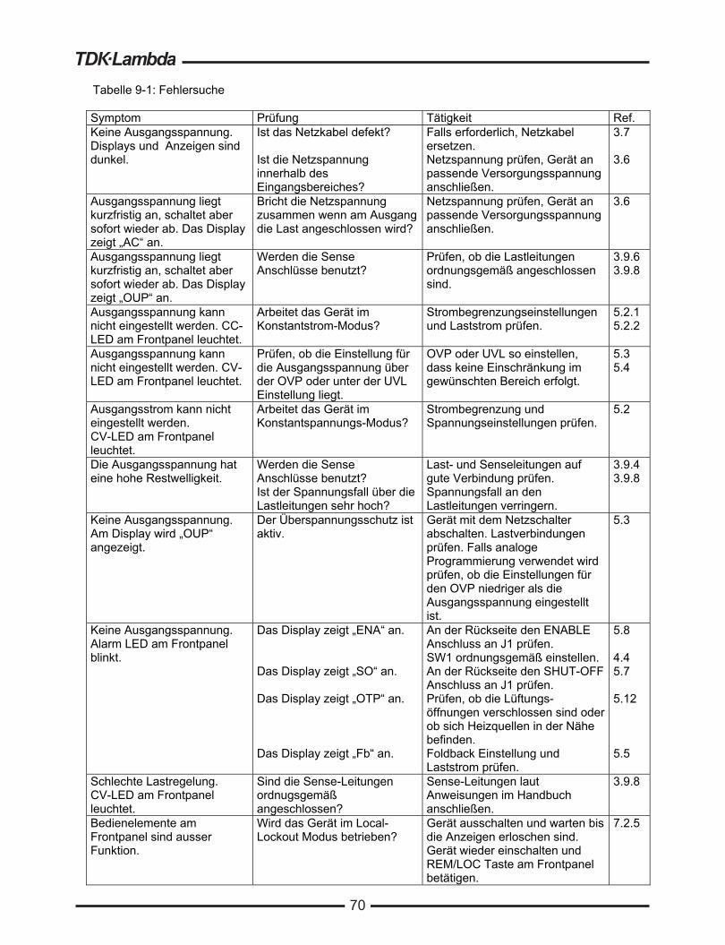
70
Tabelle 9-1: Fehlersuche Symptom Prüfung Tätigkeit Ref. Keine Ausgangsspannung. Displays und Anzeigen sind dunkel.
Ist das Netzkabel defekt? Ist die Netzspannung innerhalb des Eingangsbereiches?
Falls erforderlich, Netzkabel ersetzen. Netzspannung prüfen, Gerät an passende Versorgungsspannung anschließen.
3.7 3.6
Ausgangsspannung liegt kurzfristig an, schaltet aber sofort wieder ab. Das Display zeigt „AC“ an.
Bricht die Netzspannung zusammen wenn am Ausgang die Last angeschlossen wird?
Netzspannung prüfen, Gerät an passende Versorgungsspannung anschließen.
3.6
Ausgangsspannung liegt kurzfristig an, schaltet aber sofort wieder ab. Das Display zeigt „OUP“ an.
Werden die Sense Anschlüsse benutzt?
Prüfen, ob die Lastleitungen ordnungsgemäß angeschlossen sind.
3.9.6 3.9.8
Ausgangsspannung kann nicht eingestellt werden. CC-LED am Frontpanel leuchtet.
Arbeitet das Gerät im Konstantstrom-Modus?
Strombegrenzungseinstellungen und Laststrom prüfen.
5.2.1 5.2.2
Ausgangsspannung kann nicht eingestellt werden. CV-LED am Frontpanel leuchtet.
Prüfen, ob die Einstellung für die Ausgangsspannung über der OVP oder unter der UVL Einstellung liegt.
OVP oder UVL so einstellen, dass keine Einschränkung im gewünschten Bereich erfolgt.
5.3 5.4
Ausgangsstrom kann nicht eingestellt werden. CV-LED am Frontpanel leuchtet.
Arbeitet das Gerät im Konstantspannungs-Modus?
Strombegrenzung und Spannungseinstellungen prüfen.
5.2
Die Ausgangsspannung hat eine hohe Restwelligkeit.
Werden die Sense Anschlüsse benutzt? Ist der Spannungsfall über die Lastleitungen sehr hoch?
Last- und Senseleitungen auf gute Verbindung prüfen. Spannungsfall an den Lastleitungen verringern.
3.9.4 3.9.8
Keine Ausgangsspannung. Am Display wird „OUP“ angezeigt.
Der Überspannungsschutz ist aktiv.
Gerät mit dem Netzschalter abschalten. Lastverbindungen prüfen. Falls analoge Programmierung verwendet wird prüfen, ob die Einstellungen für den OVP niedriger als die Ausgangsspannung eingestellt ist.
5.3
Keine Ausgangsspannung. Alarm LED am Frontpanel blinkt.
Das Display zeigt „ENA“ an. Das Display zeigt „SO“ an. Das Display zeigt „OTP“ an. Das Display zeigt „Fb“ an.
An der Rückseite den ENABLE Anschluss an J1 prüfen. SW1 ordnungsgemäß einstellen. An der Rückseite den SHUT-OFF Anschluss an J1 prüfen. Prüfen, ob die Lüftungs-öffnungen verschlossen sind oder ob sich Heizquellen in der Nähe befinden. Foldback Einstellung und Laststrom prüfen.
5.8 4.4 5.7 5.12 5.5
Schlechte Lastregelung. CV-LED am Frontpanel leuchtet.
Sind die Sense-Leitungen ordnugsgemäß angeschlossen?
Sense-Leitungen laut Anweisungen im Handbuch anschließen.
3.9.8
Bedienelemente am Frontpanel sind ausser Funktion.
Wird das Gerät im Local-Lockout Modus betrieben?
Gerät ausschalten und warten bis die Anzeigen erloschen sind. Gerät wieder einschalten und REM/LOC Taste am Frontpanel betätigen.
7.2.5
69

71
9.7 Sicherungswerte Im Gerät befinden sich keine Sicherungen die durch den Anwender ersetzt werden können. Sicherungen sind als Schutz eingebaut, falls im Gerät Fehler auftreten sollten. Sollte eine Sicherung auslösen, so muss das Gerät zur Reparatur gegeben werden. Sicherungen dürfen ausschließlich von dafür geschultem, technischen Personal ausgewechselt werden. In Tabelle 9-2 sind die Sicherungswerte aufgelistet. Tabelle 9-2: Interne Sicherungen Sicherungs-Bezeichnung 3-phasig, 190-240Vac 3-phasig, 380-415Vac Eingangssicherung F301, F302, F303:
30A, 250Vac, Flink F651, F652, F653: 15A, 600Vac, Flink
F401, F402 5A, 400Vdc, mittelträge - 70

72
USER MANUAL INDEXA
B
C
D
E
F
G
H
ac cablesac failaccessoriesacknowledgeaddressadjustmentauto-restart
back spacebaud ratebipolar voltage
calibrationconfigurationchecksumcommunicationconstant currentconstant voltagecoolingcv indicatorcc indicator
daisy-chaindisplay
enableerror messageexternal resistorexternal voltage
finefoldbackfusefront panel controlfront panel locking
groundingglobal output command 56
humidityhyper terminal
I
J
L
M
O
P
R
S
ID controlinitializationinstallationisolated
J1J2J3
last setting memorylinking power suppliesline feedlocal operationlocal sensinglock front panel
maintenance
otpoutlineover voltage
parallel operationparityps_okpreview
rack mountingrear panelremote sensingremote/localregisters structureRS232RS485RXDRX(RS232)
safe startsafetyseries operationshieldspecificationsstatus controlSRQshut-offSW1
T
U
V
W
TXDTX(RS232)
under voltage limit
volts display
warrantywire size
9, 163095219, 496739
5319, 4941
67495252, 6218, 3518, 359, 1128, 3828, 38
44, 5228
34534746
3019, 37682844
25
1162
53541463
33, 46, 4717, 2650
29, 395252352644
674252
391328,36
426238, 4429
143027295849, 50, 5149, 50, 5150, 5150, 51
394395010, 6357, 58583731, 32
50, 5150, 51
18, 37
28
1, 6720
Master/SlaveMD

JAPAN
TDK-Lambda CorporationInternational Sales DivisonNittetsu Bldg. 6F, 1-13-1 Nihonbashi, Chuo-ku, Tokyo 103-0027, JapanTel: +81-3-5201-7175Fax: +81-3-5201-7287www.tdk-lambda.com
CHINA
Shanghai Branch of Wuxi TDK-Lambda Electronic Co. Ltd.28F, Xingyuan Technology Building No.418, Guiping Road,Shanghai, China 200233Tel: +86-21-6485-0777 Fax: +86-21-6485-0666www. cn.tdk-lambda.com
Beijing Branch of Wuxi TDK-Lambda Electronic Co. Ltd.Room 12B11-12B12, Unit 7 DACHENG SQUARE, No.28 Xuanwumenxi Street, Xuanwu District Beijing, 100053, CHINA Tel: +86-10-6310-4872 Fax: +86-10-6310-4874www. cn.tdk-lambda.com
Shenzhen Branch of Wuxi TDK-Lambda Electronics Co.Ltd.Room 4302, Excellence Times Square Building,4068 Yi Tian Road, Futian District,Shenzhen, China 518048Tel: +86 -755-83588261 Fax: +86 -755-83588260www. cn.tdk-lambda.com
KOREA
TDK-Lambda Corporation Seoul Office8F Songnam Bldg, 1358-6, Seocho-Dong,Seocho-Gu, Seoul, 137-862 KOREATel: +82-2-3473-7051Fax: +82-2-3472-9137www.tdk-lambda.co.kr
SINGAPORE
TDK-Lambda Singapore Pte.Ltd.Blk 1008 Toa Payoh North # 07-01/03Singapore 318996Tel: +65-6251-7211Fax: +65-6250-9171www.tdk-lambda.com.sg
INDIA
TDK - LAMBDA Singapore Pte Ltd (India Branch)No.989, 1st Cross, 2nd Floor, 13th Main, HAL 2nd Stage, Bangalore, Karnataka, India – 560 008Tel: +91-80-43550 500Fax: +91-80-43550 501www.tdk-lambda.com.sg
MALAYSIA
TDK-Lambda Malaysia Sdn. Bhd.c/o TDK (Malaysia) Sdn BhdLot 709, Nilai Industrial Estate 71800 NilaiNegeri Sembilan, MalaysiaTel: + 60 6-799 1130Fax: + 60 6 799 3277www.tdk-lambda.com.my
NORTH AMERICA
TDK-Lambda Americas Inc405 Essex Rd. Neptune, NJ 07753Tel: +1-732-922-9300 Fax: +1-732-922-1441E-mail: [email protected]/hp
UK
TDK-Lambda UK Ltd.Kingsley Avenue Ilfracombe, DevonEX 34 8ES United KingdomTel: +44-1271-856666 Fax: +44-1271-864894E-mail: [email protected]
FRANCE
TDK-Lambda France SASZAC des Delaches BP 1077 - Gometz le Chatel 91940 LES ULIS Tel: +33 1 60 12 71 65 Fax: +33 1 60 12 71 66 E-mail: [email protected]
GERMANY
TDK-Lambda Germany GmbHKarl-Bold-Str.40,D-77855 Achern, GermanyTel: +49-7841-666-0 Fax: +49-7841-500-0E-mail: [email protected]
AUSTRIA
TDK-Lambda Austria Sales OfficeAredstrasse 22,A - 2544 Leobersdorf, AustriaTel: +43-2256-65584 Fax: +43-2256-64512E-mail: [email protected]
ITALY
TDK-Lambda Italy Sales Office France Sas Succursale ItalianaVia dei Lavoratori 128/130IT 20092 Cinisello Balsamo, Milano, ItalyTel: +39-02-6129-3863 Fax: +39-02-6129-0900E-mail: [email protected]
ISRAEL
TDK-Lambda Ltd.Sales Office: Kibbutz Givat Hashlosha Tel-Aviv 4880000, IsraelTel: +972-3-9024-333 Fax: +972-3-9024-777Plant: 56 Haharoshet St., Karmiel Industrial Zone 2165158, IsraelTel: +972-4-9887-491 Fax: +972- 4-9583-071www.tdk-lambda.co.il E-mail: [email protected]
TDK-Lambda EMEAwww.emea.tdk-lambda.com
Innovating Reliable Power
IA65
7-04
-01R
ev. M
AD
0814