Embed Size (px)
Citation preview
NBSIR 73-323 Of)
A PROGRAM TO EVALUATE/IMPROVE
INSTRUMENTATION AND TEST METHODS FOR
ELECTROEXPLOSIVE DEVICE SAFETY QUALIFICATION
Hudson, Paul A.
Melquist, Dean G.
Ondrejka, Arthur R.
Werner, Paul E.
Electromagnetics Division
Institute for Basic Standards
National Bureau of Standards
Boulder, Colorado 80302
June 1973
Prepared for
DEPARTMENT OF THE AIR FORCE
Aeronautical Systems Division (AFSC)
Wright-Patterson Air Force Base, Ohio 45433

NBSIR 73-323
A PROGRAM TO EVALUATE/IMPROVE
INSTRUMENTATION AND TEST METHODS FOR
ELECTROEXPLOSIVE DEVICE SAFETY QUALIFICATION
Hudson, Paul A.
Melquist, Dean G.
Ondrejka, Arthur R.
Werner, Paul E.
Electromagnetics Division
Institute for Basic Standards
National Bureau of Standards
Boulder, Colorado 80302
June 1973
Prepared for
DEPARTMENT OF THE AIR FORCE
Aeronautical Systems Division (AFSC)
Wright-Patterson Air Force Base, Ohio 45433
U.S. DEPARTMENT OF COMMERCE, Frederick B. Dent, Secretary
NATIONAL BUREAU OF STANDARDS, Richard W. Roberts, Director

FOREWORD
This program was initiated at the National Bureau of
Standards in response to a request from the Aeronautical
Systems Division (AFSC) of the Air Force Wright-Patterson
AFB. Funding for the effort was provided by the Air Force
(Contract No. F33615 - 72 - 501 3) . The general objective was to
provide the Air Force with optimum test procedures, instru-
mentation, and test devices for qualification of weapon
systems with respect to electroexplos ive device (EED) safety.
In particular, instrumentation was required to determine
hazards to EED's on board aircraft flying in the vicinity of
Safeguard radars.
Phase I of the effort was designed to investigate and
evaluate existing instrumentation, test devices, and
facilities while Phase II was concerned with optimizing
instrumentation to meet Air Force needs. It was hoped that
existing equipment could, with modification, be adapted for
satisfactory use. As it turned out, none of the existing
stray energy monitor devices were satisfactory and develop-
ment of new devices was deemed necessary. It was decided
by ASD that the primary need was for a go, no-go type stray
energy monitor (SEM) which could be used in routine flight-
line safety checks as well as in-flight tests.
This report is divided into two parts to describe the
results of Phase I and Phase II. Each part is written as a
separate paper for presentation at the IEEE International
Electromagnetic Compatibility Symposium in New York on
June 20-22, 1973.
iii
A Phase III effort has been initiated for the purpose
of developing instrumentation systems to yield quantitative
information on EED safety at Air Force test facilities such
as Eglin Air Force Base, Florida. The new instrumentation
will employ solid state diode detectors to monitor both
pin-to-pin and pins-to-case voltages when installed in a
weapon system in place of EED's.
The report on Phase III will be issued separately
following completion of the work in September, 1973.
iv
CONTENTS
Page
PHASE I - AN EVALUATION OF AVAILABLE STRAY ENERGY
MONITORS FOR ELECTROEXPLOSIVE DEVICE (EED)
SAFETY QUALIFICATION
1. INTRODUCTION 1
2. EVALUATION OF STRAY ENERGY MONITOR DEVICES
AND SYSTEMS 3
2.1. Temperature Sensitive Paints 4
2.2. Manganin Gage-Passive Technique for
Measuring High Transient Currents 5
2.3. Thermocouple Instrumented EED's
(TCI-EED's) 8
2.4. Video Detector Instrumented EED's 11
2.5. Piston Actuator Stray Energy Monitor 12
2.6. Flight Line Stray Energy Testers 14
2.7. Miniature Recorder for use with
TCI-EED's 17
2.8. Optical Readout for use with
TCI-EED 19
3 . SUMMARY 2 0
4. REFERENCES 22
PHASE II - A NEW GO, NO-GO TYPE STRAY ENERGY MONITOR
DEVICE FOR EED SAFETY QUALIFICATION
1. INTRODUCTION 33
2. DESIGN AND CONSTRUCTION OF NEW SEM 36
3. PERFORMANCE CHARACTERISTICS 40
4. SUMMARY 42
5. REFERENCES 4 3
BIBLIOGRAPHY 54
V
LIST OF ILLUSTRATIONS
Figure Phase I Page
1 Section view of typical electroexplos ive
device (EED) 23
2 Details o£ the construction of the
TCI-EED 24
3 Output of TCI-EED as a function of
frequency at constant bridgewire
temperature 25
4 Thermocouple output characteristics with
10 GHz rf applied to bridgewire 26
5 Video diode instrumented EED developed
at Sandia Laboratories 27
6 Block diagram of test setup for piston
type SEM evaluation 28
7 Section view of SEM in mount 29
8 Average firing power of SEM's
(piston- type) versus frequency 30
,
9 Ring modulator tester 31
Figure Phase II Page
1 Section view of typical electroexplos ive
device (EED) 44
2 Field configurations in two - conductor
shielded transmission line
a. Balanced (odd mode)
b. Parallel (even mode) 45
3 Dimensions of thin film fuses 46
vi
List of Illustrations (Con ' t)
Figure Phase II Page
4 Arrangement o£ fuses for attachment to
pins-header assembly 47
5 Exploded view of complete SEM device 48
6 Circuit diagram of prototype SEM
test box 49
7 Photograph of prototype SEM test box 50
8 Block diagram of SEM test setup 51
9 a. Method for connecting SEM to
coax mount
b. Equivalent circuit 52
10 Burn-out characteristics versus
frequency for fuse type SEM 53
vii

ABSTRACT
Adequate qualification of weapon systems for EED safety-
has been a long-standing problem in the military services.
During the past 15 years various instrumentation, test
devices, and methods have been developed with some success.
In this report, available devices and instrumentation are
evaluated with respect to sensitivity to low power levels,
broadband response, ease of use, etc. This work is included
in Phase I of the program.
In Phase II the objective was to develop a new go,
no-go type stray energy monitor (SEM) with sensitivity in
the tens of milliwatts range and response up to at least
10 GHz. A description is given of the new SEM which employs
thin film fuses and monitors both pin-to-pin and pins-to-case
hazardous voltages. Safety factors obtainable with the new
device are in the 15 dB range relative to a 1 A, 1 W EED.
Key words: Electroexplos ive device safety; electromagnetic
compatability;electromagnetic interference; squib.
viii
PHASE I
AN EVALUATION OF AVAILABLE STRAY ENERGY MONITORS
FOR ELECTROEXPLOSIVE DEVICE (EED) SAFETY QUALIFICATION
1. INTRODUCTION
Electroexplos ive devices (EED's) are used extensively
by the military services, NASA and others to initiate functions
such as bomb release, rocket motor firing, aircraft engine
fire extinguishers, etc. The most common type of EED in
present use is the hot bridgewire. In this device, a fine
wire is heated by passage of an electrical current to a
temperature high enough to explode a small charge in intimate
contact with the bridgewire. This primary charge then
initiates a larger charge which performs the desired function.
The attractive features of hot-bridgewire EED's include the
large force obtained from a small volume and the relative
ease with which they can be controlled from remote locations.
Construction details of a typical hot bridgewire EED
are shown in figure 1. Normal firing occurs when a source of
electrical energy is connected across the pins and this is
called the pin-to-pin firing mode. Firing can also occur
when sufficient voltage (rf or dc) exists between the pins
and the metal case which encloses the device to cause an
arc. This is the principal pins-to-case firing mode. Another
pins-to-case firing mode occurs when rf potentials cause
dielectric- loss heating of the primary charge to its ignition
temperature. A less well documented firing mode can occur
when the header material is heated by dielectric loss due to
rf potentials either pin-to-pin or pins-to-case. Heat
generated in the header is conducted to the bridgewire causing

the primary charge to initiate. Measurements at 10 GHz
indicate that for certain EED types, as much as 96 percent of
the power absorbed by the EED goes into heating the header[l].
For this reason more investigation into this firing mode
should be carried out.
Electroexplosive devices are usually rated in terms of
their no-fire current. For example, a typical EED type has
a 1 A no-fire current and this current is just below that
which begins to fire a small number of devices in a large
population. Typical 50 percent fire currents for this device
is 1.3 A while the all-fire current may be 1.8 A. The latter
is the current which will fire 100 percent of a given
population with 95 percent confidence factor. In a weapons
system, such a device would have approximately 5 A applied
to its input pins to insure firing with a reasonable safety
factor. The energy source is normally a dc supply or a
capacitor discharge, and firing is initiated by means of a
switch. Time to fire after application of power varies
from a few microseconds to a few milliseconds.
Unfortunately, EED ' s are subject to unintended initiation
caused by pickup of stray electrical energy by the EED and
its associated circuitry. Sources of this stray energy
include static charges, on-board rf sources (Avionics) in
aircraft, external rf sources such as radar, lightning
discharges, and switching transient pickup from adjacent
wiring. A common cause of unintended initiations is
incorrect or faulty wiring within the weapon or system
(e.g.,aircraft) [2 ]
.
It has become common practice for the military services
and NASA to test new and/or modified weapons, aircraft,
missiles, etc. for EED safety prior to deployment in the
field. For the most part, these tests are designed to
evaluate susceptibility to EED firing by stray rf energy.
2
Instrumentation and methods used for these tests will be
described later in this report. Tests are also required on
aircraft on the flight line prior to the loading of ordnance.
These tests are somewhat simpler than the qualification tests
mentioned above but are, nevertheless, very important. A
major part of the flight line tests can be made with dc and
low frequency instrumentation to reveal the presence of
voltages at the EED jack or receptacle. To test for the
presence of rf and microwave power, a device which responds
to low levels of high frequency energy must be used. A
single device which responds to static, low level dc , rf and
microwave energy in both pin-to-pin and pins-to-case modes
would be ideal. At present, no such device exists which
yields the required 20 dB safety factor in all firing modes
at frequencies up to 10 GHz. That is, the test device is
required to respond to power levels 20 dB below that necessary
to fire the actual EED, in any firing mode.
2. EVALUATION OF STRAY ENERGY MONITOR DEVICES AND SYSTEMS
During the past 15 to 20 years test devices and facilities
have been developed to assess the susceptibility of weapon
systems to the inadvertant firing of EED's. Test devices
range from the go, no-go type (SEM piston actuator) to those
which yield quantitative information (thermocouple instru-
mented EED's) as shown in the following list. Test facilities
exist at Naval Weapons Laboratory, Dahlgren, Va., Picatinny
Arsenal, New Jersey and Eglin AFB, Florida.
It is the purpose of this section of the report to
describe and evaluate the various devices and facilities which
now exist. In some cases the information upon which the
evalutions are based was obtained by testing in NBS
3

laboratories. In others, information was obtained from the
literature, discussions with knowledgeable people and
observations at test facilities.
2.1. Temperature Sensitive Paints
So-called temperature sensitive paints are chemical
substances which melt rather abruptly at a given temperature.
The range of temperatures extends from 310K to 1640K and as
many as 100 compounds, each of which corresponds to a discrete
temperature, are available within this range.
To use these paints for stray energy monitoring, they
are applied directly to the bridgewire of an EED from which
the primary and secondary charges have been removed. Before
applying the paint, the input lead-header-bridgewire assembly
must be removed from the metal case. A small brush is usually
used for the application after which the assembly is replaced
inside the case.
After exposure, the assembly is again removed from the
case and the bridgewire examined for "beading" of the paint
which would indicate that the paint had melted. Both the
paint application process and examination for "beading" must
be done with the aid of a microscope. This is perhaps the
most serious drawback to the use of temperature sensitive
paints. Other factors which tend to limit their usefulness
include ambient temperature variations which cause the power
required to melt the paint to vary. Thus, the ambient
temperature must be measured and corrections applied for
ambients other than 295K.
The power required to melt a certain paint (#45) at a
293K ambient for various bridgewire sizes has been reported
in the literature [ 3] . For a 0.3 A no-fire EED, the paint
melted with 6 mW input yielding a 17 dB safety factor. On a
4
0.68 A EED bridgewire, the paint melted at 38 mW input for
11.5 dB safety factor. These are below the 20 dB factor
specified by MIL-E-6051C.
Our overall evaluation is that temperature sensitive
paints are at best of marginal utility for use by the
Air Force. The reason for this is the extreme care which
must be exercised in applying the paints to a bridgewire
and in determining whether melting has occurred after
exposure. In addition, they do not indicate hazardous
pins-to-case voltages.
In specially designed devices these paints could be
useful. For example, the paint could serve as a cement to
hold down a small spring- loaded lever which is released when
the paint melts and gives an easily read visual indication.
Other similar designs are also possible.
2.2. Manganin Gage - Passive Technique for Measuring High
Transient Currents
The manganin gage was developed at Lawrence Radiation
Laboratory by Robert Parker in about 1969 [4]. The device is
designed to measure the energy in short electrical transients2
(/'i R dt) from which the current can be calculated. It is
fabricated from a thin tapered strip of metal (usually manganin)
and is coated with a uniform layer of temperature sensitive
paint. Typical dimensions are as follows:
width at narrow end - .0762 mm
width at wide end - .1524 mm
length - 2 . 54 mm
thickness - 0.127 to 0.0254 mm
A current pulse will cause heating in the taper and
consequently melting of the temperature sensitive paint. By
observing where the melt line occurs, one can determine the
S

energy in the pulse. An expression has been derived which
provides a measure of the energy from simply measuring the
distance to the melt line. This latter expression is:
^ d C h^AT (a + ku)^ RxlO"''-^
R/i^dt = 2 ^P
where
2R/i dt = energy (J)
Cp = specific heat (Joule per kilogram Kelvin)
d = density (kilogram per cubic meter)
h = thickness of material (millimeters)
AT^ = melt temperature minus ambient (Kelvin)
a = width at narrow end (millimeters)
k = slope of taper
p = resistivity (ohm-m)
u = melt distance (millimeters)
R = total resistance of gage (ohms)
All terms in the right-hand side of the equation are known or
can be easily measured. Therefore, the value of the integral
can be determined.
The validity of measurements made with the gage is based
on the assumption that the heating process is adiabatic,
i.e., that no heat is lost to the surroundings. This as-
sumption is valid for very short current pulses of the order
of a few tens of microseconds. Used in this manner, the
device is sensitive to relatively small amounts of energy.
Values of energy for which the manganin gage is useful, range
6
- 3from 0.273 x 10 Joule for a .0127 mm thickness unit to
_ 32.2 X 10 Joule for a larger .0254 mm thickness unit. By
comparison, the energy required to fire EED's ranges from
8 X 10"^ Joule for a Mark 1 squib to 257 x lo"-^ Joule for the
CCU-l/B ejection cartridge [ 5 ] . For many EED types, the- 3
average firing energy is in the range 20 to 100 x lo Joule.
In terms of energy the manganin gage is 10 to 100 times
more sensitive than typical EED's. However, this sensitivity
is dependent upon delivery of the energy in a relatively
short time interval. For example, it might be supposed that
the device is useful for measurement of hazards from radar
pulses which usually have durations from 1 to 10 ys . We
can then compute the minimum power required using minimum
energy value given above. That is,
c ^min 0.273 xio'^j 07 tw= —r = -z= Z/.3 Wmm t in 1 n " o
10 X 10 sec
for a 10 ys pulse and 273 W for a 1 ys pulse must be absorbed
by the gage to yield a minimum reading. Radiated power
densities sufficient to provide the above levels of power
at the device input are not likely to be encountered at any
reasonable distance from a radar.
In many respects the manganin gage is similar to an
EED instrumented with temperature sensitive paint on its
bridgewire as described in 2.1. above. For example, the cross-
sectional area of the gage is .02 mm (.0762 mm x .0254 mm)
at the small end which is approximately equal to that of a
.0254 mm diameter bridgewire. The lengths are also comparable,
1.52 mm for the EED bridgewire and 2.54 mm for the manganin
7

gage. Both must be examined under a microscope to observe
paint melt. For this reason and the fact that the manganin
gage is designed for short, high current pulses, its use by
the Air Force is considered marginal. It would, in fact, be
less useful than a Mark I EED using temperature sensitive
paint.
2.3. Thermocouple Instrumented EED's (TCI-EED's)
Thermocouple instrumented EED's are, at present, the
most commonly used type of test device at military facilities.
Originally developed by Denver Research Institute in the late
1950's, the device consists of an EED constructed with the
usual bridgewire but without the primary and secondary charges.
A thin film thermocouple is inserted into the back-end of
the EED with the hot junction very close to the bridgewire.
Removal of the primary charge from intimate contact with the
bridgewire causes a change in the thermal properties of the
device. In particular, heat loss is decreased and the time
constant is increased so that the TCI-EED does not exactly
simulate the thermal characteristics of the EED, but does
simulate the electrical impedance with good accuracy. Barker
and Fry[6] have calculated a thermal ' s imulation factor, T/T^,
for instrumented and actual EED's and the value of this is
generally of the order of 0.5 for the devices tested.
Heating of the hot junction is generally believed to
be by means of heat conduction through the film of air
separating the bridgewire and the junction. The cold junction
is on the same substrate as the hot junction and hence ambient
temperature changes have only a small effect on the thermo-
couple output. Details of the construction of the TCI-EED
are shown in figure 2.
8
The junctions are usually bismuth- antimony and these
metals yield a very high thermal emf. Thus, it is possible
to detect input power levels far below (at least 30 dB) that
required to fire a 1 A, 1 W, no-fire EED.
The thermocouple output is normally fed via wires to
a suitable voltmeter or millivolt recorder. When performing
rf tests, these wires can couple energy into the thermocouple
and/or the structure in which the TCI-EED is located and
cause inaccurate readings and/or burn-out of the thermocouple.
This constitutes a drawback to the use of TCI-EED 's. External
thermocouple wires can be avoided by use of a miniature
recorder which is small enough to be enclosed within the
structure (pod, missile, etc.) in which the EED is located.
Other means include converting the electrical signal to an
optical one and coupling to external instrumentation via
optical fibers and the use of voltage controlled oscillators
to telemeter the information to remote recorders. Miniature
recorders have been used successfully at Naval Weapons
Laboratory while the fiber optics technique is used at
Picatinny Arsenal.
Further limitations of TCI-EED's include the lack of
capability for measuring pins-to-case voltages and a
relatively large (up to 200^) rf-dc difference error[7].
This error arises due to coupling of rf energy from the
bridgewire to the thermocouple. In the latter case, the
energy coupled into the thermocouple causes circulating
currents to flow in the hot junction resulting in much higher
thermocouple emf's than for an equivalent amount of dc power
in the bridgewire. (Prior to use, TCI-EED's are calibrated
by applying measured amounts of dc power to the bridgewire.)
While the rf-dc difference error is in the direction of
greater safety, it could cause rejection of an otherwise
9

safe system. It should be noted that corrections can be
applied for this effect because the increase is relatively
slow and monotonic.
Measurement of the rf-dc difference for TCI-EED's
constructed at Los Alamos Scientific Laboratory have been
made at NBS and results are shown in figures 3 and 4. Note
that the rf-dc difference increases with frequency. These
measurements were made by recording the thermocouple output
first with dc power input alone and then with 95 percent rf
power and 5 percent dc power. The bridgewire temperature
was held constant by adjusting the power to hold the bridge-
wire resistance constant. The 80-20 plat inum- iridium
bridgewire has an adequate temperature coefficient of resistance
to allow precise measurement and control of its temperature.
To evaluate the TCI-EED as a stray energy monitor, it
can yield accurate data for pin-to-pin firing hazards at dc
and frequencies up to approximately 1 GHz. At higher
frequencies the device is useful as an indicator of stray
energy but uncompensated data is overly conservative due to
rf eddy currents in the thermocouple and dielectric heating
of the header. The magnitude of the error varies from unit
to unit but may be as great as 200 percent. The perturbing
effects of the thermocouple output leads which may couple
to an rf field can be avoided at the expense of more complex
instrumentation. Perhaps a suitable solution to this problem
would be the use of carbon impregnated teflon leads which do
not perturb the rf fields and hence do not couple to them.
These electro-magnetically "invisible" conductors may, however,
introduce some electrical noise into the measuring circuit.
10
2.4. Video Detector Instrumented EED's
The video detector was developed in order to overcome
the low voltage output of the TCI-EED. Figure 5 shows such
a device developed by R. J. Sons [8] at Sandia Laboratories.
Note that this circuit is a voltage doubler with a balanced
output. The output of the detector is almost 0.1 V for 1 mW
input power while a TCI-EED with the same input power delivers
only a few microvolts. However, TCI-EED output is electrically
isolated from the input (except for some coupling above 1 GHz)
while the video detector outputs are connected electrically
to the input; complications may arise, especially in three
and four pin EED's.
As shown, this diode detector is not designed to respond
to pin-to-case voltages but it should be possible to develop
a unit which is sensitive to pin-to-case potentials. The low
frequency operation of the diode detector assumes that there
is very little current drawn through the diodes. This implies
that the diode load is a very high impedance amplifier and
could lead to input noise problems, but this should not be
considered a serious limitation. Of course as the frequency
increases, more current passes through the junction capacitance
of the diode and this causes the detector input impedance to4
drop. Since the dynamic diode resistance is higher than 10
ohms, the shunt capacitance begins to dominate the total
diode impedance at frequencies above a few hundred megahertz
and the effects of this loading will have to be evaluated.
Our tests have revealed one interesting fact that is
often overlooked. When an EED is excited in the pin-to-pin
mode, there exists some voltage from pins-to-case because
some of the field lines terminate on the case. This means
that any SEM designed to respond individually to both pin-
to-pin and pins-to-case potentials will have an output from
11
pins-to-case when the unit is excited in the pin-to-pin mode.
On the other hand, there should be no output from pin-to-pin
when the device is excited in the pins-to-case mode. This is
what is commonly referred to as common mode rejection. In
order for any stray energy monitor to give a quantitative
indication, it must be designed so that pins-to-case voltages
do not affect the pin-to-pin measurement.
2.5. Piston Actuator Stray Energy Monitor
This type of SEM has a small piston which is highly
visible if the power absorbed by it exceeds some value. As
originally designed, the piston actuator was to have been a
more sensitive replacement for the EED for test purposes.
The intent was to replace the EED's with SEM's and operate
the weapon system in the desired manner during a test. A
quick visual inspection of the SEM's following a test would
reveal the presence and location of unsafe conditions . Since
the SEM is more sensitive than the EED (i.e., 0.1 W versus
1 W for dc power) , there is a known minimum safety margin
if the SEM does not actuate.
Test facilities which use these SEM's have had the
experience that the SEM did not operate when the rf fields
present were thought to be sufficient to cause SEM firing.
The usual conclusion is that the SEM is not properly
responding to the rf energy. NBS has conducted some careful
tests to show that the net rf power required to fire SEM's
is up to 8 times larger for rf power than for dc power.
Figure 6 is a block diagram of the test setup used. The
power absorbed by the SEM is the difference between the
incident power and the reflected power as measured by the
reflectometer and the two power meters.
12
The only assumption is that the test mount not absorb
power. Care was used in the design of the SEM mount to make
it as nearly lossless as possible. Figure 7 is a cross section
view of the SEM in the mount which connects it to the normal
7 mm coaxial line. Note that the tapered outer and center
conductors very nearly maintain a 50 ohm impedance while
changing the size of the coax line down to the diameter of
the SEM.
Since the mount has no observed resonances and there is
nothing in the mount to absorb appreciable power, the
difference between incident power and reflected power can be
assumed to be the power absorbed by the SEM. The 0 . 3 dB
accuracy of these power measurements is dependent upon the
apparent directivity of the two directional couplers . The
tuner located between these two directional couplers has
the effect of greatly raising this directivity and in fact
makes a tuned reflectometer
.
Figure 8 shows the average power required to fire typical
SEM's as a function of frequency. The firing power appears to
peak between 6 GHz and 8 GHz at a level of approximately 0.8 W.
Further tests showed that the SEM lead wires (pins) , which
are made of iron, absorb significant power in this frequency
range. This has the effect of reducing the SEM firing
sensitivity. The NBS data on SEM firing characteristics was
obtained from firing 150 units.
Although there is uncertainty about the exact difference
in firing power (safety margin) between the SEM and any
particular EED at some arbitrary frequency, the SEM is
usually more sensitive than EED's tested. The SEM exhibits
a rather well behaved impedance characteristic over a wide
frequency range but does not actually match an EED impedance.
13

Since the SEM does not match a particular EED impedance,
the idea of using an EED as a test item has some merit. The
secondary explosive is removed from the EED, leaving only
the small primary explosive on the bridgewire. A safety
margin is achieved by increasing the irradiation power by some
known amount and checking for fired EED ' s
.
Recommendations . The piston actuator and the modified
EED's are useful test devices and could be used for in-flight
testing and for testing after system modification to reveal
gross effects such as shorts and wiring errors which would be
overlooked by non- operational tests.
2.6. Flight Line Stray Energy Testers
There are situations on the flight-line where it is
necessary to check EED firing leads for the presence of
unsafe conditions. These conditions may be the result of
worn insulation, corrosion, improper connection of wires,
broken connectors, inoperative relays or short circuits to
other wires. Typically, the firing circuits are short-
circuited at all times prior to EED firing and the condition
of this short circuit should also be checked.
Two prototype testers were built in 1961 by Denver
Research Institute. The first unit is in some aspects the
more sophiticated of the two and will be the one described
in detail. Where there are significant differences in
performance or operation between the two units, these
differences will be discussed.
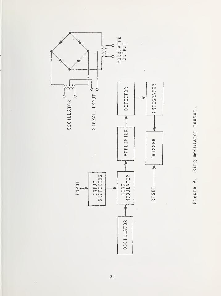
The tester using a ring modulator was designed to respond
to dc voltage of either polarity and also to ac up to several
hundred hertz. Calculations of the safe allowable energy
in a firing circuit determines the gain and sensitivity
14

requirements for the tester. This energy is about 1/lOOOth
of the marginal firing energy of the particular EED. Since
these levels are low compared to the maximum no-fire current,
it is apparent that stability rather than accuracy is the
dominant factor. For this reason, the ring modulator is
a good circuit to use since it can have sufficient sensitivity
without the use of any preamplification . Figure 9 is a
block diagram of the tester with the ring modulator.
The ring modulator is an ac diode bridge circuit whose
20 kHz output is zero at bridge balance. Any input current
(ac or dc) will cause one pair of bridge diodes to conduct
thereby changing their 20 kHz impedance in such a way as to
cause bridge unbalance. The resulting 20 kHz signal is
amplified, detected, integrated (approximately the same time
response as the EED) and its level compared to the arbitrary
unsafe level. If the output is large enough, a silicon
controlled rectifier conducts through a lamp. Once fired,
the SCR will continue to conduct until the circuit is
intentionally opened by depressing the reset button.
The design criteria for the tester using magnetic
amplifiers is similar to the ring modulator tester. The
unsafe indicators are also similar. The primary difference
is that the ring modulator accepts the stray energy directly
while the mag-amp unit uses a thermocouple instrumented
EED (TCI-EED) to convert the stray energy to a dc voltage
which must be amplified. The choice of mag-amps is based
on their stable zero point, gain stability, and ruggedness.
The time response of the TCI-EED is such that overload
protection is not normally fast enough to protect it.
Therefore, the TCI-EED must be considered expendable. This
might be a disadvantage. Another disadvantage is the need
15

for 400 Hz, 110 V power to supply the mag-amps. Without
a converter of some type, the unit cannot be battery operated.
The advantage is that the tester could be used for rf
measurements as well as ac and dc.
Both units are designed to check the condition of the
short circuit in the firing leads. Each tester supplies a
test current through either the input resistor (ring mod.
unit) or the heater of the TCI-EED (mag-amp unit). If the
short is indeed present, there will be insufficient voltage
to cause the indicator to function. This same current will
serve to calibrate the unit when the leads are not connected
to a short circuit.
The testers are relatively easy to use as the operator
is merely required to connect two test leads to the circuit
in place of the usual EED . The operator then selects the
sensitivity by rotating the selector switch to the proper
EED type. If there is a dangerous amount of stray signal
present on the circuit, the no-go light functions. If the
light does not function, the circuit is considered safe.
The condition of the firing circuit is then tested by pressing
one more button, the "Test Current" button. Again, an unsafe
condition is indicated with a light, and a safe condition
gives no light.
Other advantages of the tester include the following.
The accuracy of the device is more than adequate
for its intended use.
The testers are provided with the means for
self calibration.
The indication of unsafe energy or unsafe circuits
is positive and does not require interpretation
by the operator.
The units may be modified for any particular
EED sensitivity.
16

The testers have certain shortcomings such as the fact
that the ring modulator unit does not detect rf signals and
neither of the units are suitable for in-flight use. Both
units are designed to be used external to the weapon or
aircraft; however, they could probably be used as in-flight
testers with some modifications to the aircraft or weapon.
Neither unit is completely free from some source of external
power (batteries or dc to ac converter)
.
Recommendations . A perusal of selected accident reports
indicates that some form of dc and low frequency pre-flight
safety check would be desirable. Either of the DRI type
stray energy testers could be very useful for this purpose.
2.7. Miniature Recorder for use with TCI-EED's
The thermocouple instrumented EED described previously
requires some type of readout instrumentation. One type
used at the Naval Weapons Laboratory (Dahlgren) is a
photographic recording galvanometer. The dimensions are
127 mm in diameter by about 610 mm long and the unit can
usually be located entirely within the larger weapons being
tested. Up to 14 separate galvanometer movements can record
simultaneously on the same chart. A smaller unit is also
available for applications where space is limited.
The output from the TCI-EED is fed to a galvanometer
winding which has sufficient sensitivity to deflect with very
small currents (microamps or less) . A spot of light reflects
from a mirror located on each of the galvanometer movements
and is focused onto the light sensitive chart paper. The
chart is exposed during a measurement, after which it can be
removed from the instrument and developed using a wet process.
The sensitivity of the instrument is a function of the
particular galvanometer movement chosen and usually decreases
for the faster responding types. The response time of the
galvanometers in use is 20-50 milliseconds.
17
The instrument is powered by batteries which are housed
in a removable canister to simplify recharging. This power
pack usually takes up more than half the total volume of
the recorder.
In evaluating the recorder several favorable features
were noted. The fact that the recorder yields a permanent
record allows an evaluation of the input power to the
TCI-EED as a function of time. The recorder can usually
be located entirely within the weapon system being evaluated.
Thus, there are no external wires to perturb or couple to
rf fields. Also, instrumenting a weapon system does not
require modifying the umbilical connector or weapon skin as
is necessary when externally telemetering the data. It
allows testing of relatively complex weapons systems having
several EED's since the recorder can accommodate up to 14
recording channels.
A few undesirable features were also noted. The delay
between the occurrence of the measurement and the availability
of the data can be a serious shortcoming. Overload conditions,
as well as insufficient signal conditions, can result in
useless data. These situations do not become obvious until
the chart has been developed. In smaller weapons there may
not be sufficient room to locate the recorder. In this case
the recorder must be located outside the weapon and this
requires wiring between the weapon and the recorder. The
need for developing the exposed chart by a wet process
requires the availability of a processing facility. The use
of galvanometers in the instrument requires that it be stable
during a test. Thus, it is not suitable for in-flight tests.
The following recommendations are made for effective
use of the recorders in EED testing.
18
Acceptance testing--The recorder is well suited
to initial qualification testing of relatively
large weapons systems, such as the HERO tests.
For this type of test, time, equipment, and
qualified personnel are available to perform
the large scale modifications necessary to
install the recorder in the weapon system.
Post modification testing--The recorder can be
used in a few instances for testing a weapon
system after a field modification. This is
practical only when the recorder can be installed
without additional modification to the weapon.
Often in this situation, neither the time nor
the equipment is available to mount the recorder.
2.8. Optical Readout for use with TCI-EED
Another type of readout instrumentation used with
TCI-EED's is a system which uses an optical transmission
link. Problems with the miniature recorder system described
above include relatively large size, large power requirement
and the fact that it is not real time. These limitations
are mostly overcome with the optical system used by Picatinny
Arsenal
.
In this system, as many as 28 TCI-EED outputs are
commutated and measured in sequence at a rate of 785 per
second. The commutated thermocouple outputs are then applied
to a sensitive voltage controlled oscillator (VCO) . This
voltage to frequency conversion obviates the need for stable
dc amplifiers. The VCO output drives a power amplifier
which in turn drives a light emitting diode (LED) at a
frequency which is proportional to thermocouple voltage. The
operations described thus far are accomplished inside the
19
weapon being tested for susceptibility. The total package
is, however, smaller and requires less dc power than the
miniature recorders.
The output from the LED is transmitted through a
length of fiber optic tubing to an rf data telemetry link.
The section of fiber optic tubing is a means of getting the
thermocouple voltage information out of the weapon under test
without disturbing the irradiating rf field or coupling rf
energy into the thermocouple.
The telemetry receiver feeds information to both a
magnetic tape storage and a video display. Observing the
video display gives data in almost real time. This system
would be used for the same type of testing as the miniature
recorder system and requires nearly equal weapon system
modification, etc. It would not normally be sensitive to
vibration, however, and is typically smaller than the
miniature recorder.
3 . SUMMARY
There are several stray-energy monitor devices presently
used for electroexplos ive device safety testing. The
National Bureau of Standards has evaluated some of these
devices and has found that no single device is entirely
satisfactory for all test situations. The following summary
lists the most useful devices for three general test categories
Type of Test Useful Device
System TCI-EEDQualificationandAcceptanceTesting
Video Diode
Comments
Quantitative output.No pins-to-case information.Errors increase above 1 GHz.Used with miniature recordersor fiber optic data outputsystem
.
Needs further development.
20

Type of Test Useful Device
Fly-by Piston Actuatoror PostModi ficationTesting
Manganin Gage
EED with Temp.Sensitive Paint
Comments
Go, No-Go.Possible uncertainty in safetymargin due to rf impedancedifference between SEM and EED.Decreasing sensitivity above1-2 GHz.
Useful for short pulse ortransient signals.
Repeated tests using differenttemp, ranges can estimatemagnitude of stray energy.
Flight-Lineor PostModificationPre-FlightTest
Piston Actuator Go, No-Go.
Volt-Ohmmeteror
Flight LineStray EnergyTester
Good for finding wiring errors,faulty cables and relays, etc.DC to 30 MHz.
This list is to be used as a guide and not as justification
for discarding any one particular test procedure or device
in favor of another. Most of the test devices are useful
in the right situation but can lead to erroneous conclusions
when used beyond their capabilities.
21
4. REFERENCES
Barker, D. B., et al , Research and development
leading to perfection of instrumentation of electro-
explosive devices, Vol. II, Denver Research Inst.,
Univ. of Denver, March 1962, ASTIA No. 278385.
Air Force Accident Report (Restricted)
.
Mason, B. A., The use of tempilaq 45 in RF hazard
trials using the X2/H series of igniters, Royal
Armament Research and Development Establishment
Memorandum 36/64, July 1964. (Cataloged by DDC
as Ad No. 445156.)
Parker, Robert, A passive technique for measuring
high transient currents, Proc. 25th Annual ISA
Conference, Phil., Pa., Oct. 26-29, 1970.
Progress Report, Evaluation of electroexplos ive
device response to electromagnetic radiation,
Los Alamos Scientific Laboratory, Project 5610,
Task 01, March 1, 1972 to April 30, 1972.
Barker, D. Boyd and Richard K. Fry, A study of
the simulation of instrumented to loaded EED ' s ,
1963 Proc. 2nd HERO Congress, Philadelphia, Pa.
Hewitt, Jack G., Jr. and Wesley R. Johnson,
A method for meeting the ordnance susceptibility
test requirements of MIL-E-6051D, International
Electromagnetic Compatability Symposium Record,
July 1972 (IEEE 72 CH0638-7 EMC).
Sons, Richard J., A method for calibrating video
detector instrumented electroexplosive devices for
use in electromagnetic radiation testing. Technical
Memorandum SC-TM-68-273 (Sandia Laboratory), June 1968.
Van Allen, John and Franklin E. White, Stray energy
tester, AF Contract 29 (601) -2843 (Univ. of Denver),
July 15, 1961.
22
(6.88 MM) DIA.
.437"(11 .11 MM)
Figure 1. Section view of typical electroexplosivedevice (EED)
.
23

24

25
400
350
300
250
200
150
100
/
/
/
/
CALCULATEDOUTPUT - V^(.
(BRIOGEWIRETEMPERATURE)
MEASUREDOUTPUT - V
TC
THERMOCOUPLE OUTPUTDC CURRENT OH ERIDGEWIRE
J L J L0 2 4 6 8 10 12 14 16 16 20
TIME IN HINUTES AFTER APPLICATION OF RF TO ERIDGEWIRE
a. Thermocouple output -- cons taut rf power.
22
400r-
350
300
250
200
150
100
TC OUTPUTFOR COflSTAHT
bRIDGEWIRE RESISTANCE(RF APPLIED)
_L
THERMOCOUPLE OUTPUTDC CURRENT ON BRIDGEWIRE
_L I _L
4 6 8 10 12 14 16 18 20
TIME IN HINUTES AFTER APPLICATION OF RF TO BRIDGEWIRE
22
b. Thermocouple output - -bri d^ewire tem.perature constant
Figure 4. Thermocouple output characteristics with 10 GHz
r£ applied to bridgewire.
26
27
enO
_l 1—CD <C
1—
1
s:UJh-> t—<:
i
o3 aiO
Dd ^—UJ <t—_1 o1—
H
00Ll_ 1—
1
CO —1-a a.oCO oo
TI
I
_L
UJCO —1-o Q-O ZDro Oo
o onI—t ui 1—> Q OOUJ Z UJQ rD [—
\— oc: ocO UJ UJUJ rs 1—_l O UJLi_ a_
enUJ
>- 1—I I—X O
__1
2: q: d::
UJ UJ UJQ 3 I—I—I O UJo Q- s:
I 1
I I
I UJ DC I
1 2: I— OI ui <: I—00 q; •—
I
I UJ 3 I
, D- 00
Io
I
t I
o4->
V)
•HPU
5h
Om
+j
V)
ptfl •
(U Co•H
m +->
O 03
^ >
c3
•H 2TH m
CO
u <u
O Ph
PQ +J
•H
o3: h-
28

29
o
— cn
— CO
I I \ I \ L
zn.
CJ3
>-
UJZDcy
u_
OOoooCO
oo
O OO O^ CSJ
(U
>^+->
I
o
V)•H
wCO
mo
o •
U
•HcrCD
03 P
>< >
oo
(D
•HPL,
30
31
PHASE II
A NEW GO, NO-GO TYPE STRAY ENERGY MONITOR
DEVICE FOR EED SAFETY QUALIFICATION
1. INTRODUCTION
There has been a long-standing need for a sensitive,
broad-band, reliable, go, no-go type stray energy monitor
(SEM) device in testing weapon and space systems for electro-
explosive device (EED) safety. Such devices are required, for
example, in routine pre-flight testing of aircraft prior to
loading of ordnance. Other uses include in-flight testing
of new or modified aircraft and to evaluate hazards of ground
radars and other high power rf sources.
The term "stray energy monitor" refers in a broad sense
to a class of devices which are used in safety qualification
testing of systems. For the most part, these devices monitor
power rather than energy. In practice, they are connected to
the firing circuit in place of the actual EED's. Ideally, the
SEM devices actuate at lower power levels than the EED's,
which they replace and thus yield certain safety margins.
These may differ depending on the situation. Where an
accidental EED firing would be a hazard to life or cause
extensive property damage, large safety margins (20 dB) are
required. In less critical cases, lower margins may be
allowed.
To conform with current usage in the literature, the
terms pin and lead refer to one and the same thing. Pin may
be thought of as that part of the input lead wire which lies
inside the case while lead may be thought of as that part
lying outside the case.
33

The normal firing mode of EED's occurs with the firing
voltage connected pin-to-pin as shown in figure 1. These
devices can also fire with accidental pins-to-case voltages
(dc or rf) which may arc through the primary charge from
pins-to-case. Thus, a suitable SEM device should monitor
pins- to-case (p-c) voltage as well as pin- to -pin (p -p) power.
Other possible firing modes in EED's include heating of
the header material due to dielectric losses and direct
heating of the primary charge due to its dielectric loss in
rf and microwave fields. These two modes have not been
fully evaluated and the device described in this paper was
not designed to monitor for accidental firing in these modes.
A description and evaluation of existing SEM devices
and appropriate literature references are given in a companion
paper[l]. Most of these devices were developed during the
past fifteen years during which EED's came into large scale
use in weapon and space systems. A brief summary of the
various types and their performance characteristics are given
here for comparison with the new SEM described in this paper.
Existing SEM's can be divided into two basic types,
namely the go, no-go type and the quantitative type. The go,
no-go type merely indicate that some power or energy threshold
has been exceeded during test. Devices of this type include
the piston actuator SEM which is similar to an EED in that it
consists of a 2 ohm bridgewire and a small primary charge.
When the primary charge detonates, a small, captive piston
in the device ejects and indicates the fired condition.
Unfortunately, the power sensitivity of the piston SEM varies
from 0.08 W at dc to nearly 1 W at 8 GHz. Since typical EED's
fire at approximately 1.3 W, the above sensitivity at 8 GHz
provides very little safety margin. Required safety margins
are of the order of 20 dB in accordance with MIL-E-6051D and
hence the piston SEM is unsatisfactory at rf and microwave
frequencies
.
34
Another type of go, no-go SEM employs temperature
sensitive paint which is applied to the bridgewire of a low
power EED such as the Mark I. Following a test, the device
is disassembled and the paint on the bridgewire is examined
under a microscope. If the paint melted during a test, its
texture will change from that prior to melt. Both the
application of the paint to the bridgewire and the examination
after test are tedious operations. In addition, judgment of
the technician is required in determining whether the paint
melted during a test. Because of the inconvenience in use,
the temperature sensitive paint type SEM is considered
marginal. It should be noted, however, that sensitivities of
less than 10 mW have been reported in the literature [ 2 ]
.
A third go, no-go SEM is the so-called manganin gage [3].
It also employs temperature sensitive paint but on a tapered
heater. The tapered heater allows estimation of the energy
absorbed, rather than of power. Usefulness of this device is
also considered marginal for the same reasons mentioned
previously for the device employing paint on a bridgewire.
In addition to the deficiencies mentioned above, none
of the present devices were designed to detect pins-to-case
voltages. The present devices were therefore deemed inadequate
to meet requirements established by the Air Force. The next
step, then, was to develop a suitable SEM device and it is
the purpose of this paper to describe its design and con-
struction. It should be emphasized that the device described
was designed to detect only those electrical hazards which
heat the bridgewire or can cause arcing from pin-to-case.
35
2. DESIGN AND CONSTRUCTION OF NEW SEM
Prior to beginning the design of the new SEM, an analysis
was made of the electromagnetic field configurations into and
inside an EED. As shown in figure 1, the EED circuit consists
of a pair of ungrounded leads which feed into the case through
the header. The SEM is constructed in the same way. It is
assumed that electromagnetic energy, which may be picked-up
on the lead wires, is conducted into the EED (or SEM) through
the input leads. The input leads may form a balanced pair of
conductors (odd mode) and the EM field configuration inside the
EED would be as shown in figure 2a. The leads can also form
a parallel pair(even mode) with shield(case) return and the
field pattern would be as shown in figure 2b.
A more likely occurrence is that an EM field excites
both patterns simultaneously in some proportion. The resultant
composite pattern is obtained by superimposing the modes. As
can be seen, the EM fields at one of the pins (to case) is
reduced and is enhanced at the other. With the proper phase
and amplitude relationships, the p-c field at one pin could
be zero. To cover this eventuality, the SEM is designed
with a thin film fuse from each pin to the case.
The principal performance characteristics desired in
designing the new SEM were the following.
1. Respond to both pin-to-pin power and
pins-to-case voltage.
2. Power threshold in the 10 mW range for p-p
voltages. Voltage threshold of 10 V for p-c
hazards.
3. Flat sensitivity over the frequency range dc
to 10 GHz.
4. Simulate electrical and thermal characteristics
of typical EED's.
36

These characteristics were arrived at in consultation with
the sponsor and were considered the design goals. The 10 mW
power sensitivity was specified so as to yield a 20 dB safety
factor relative to a 1 A, 1 W, no-fire EED . These employ a
1 ohm bridgewire.
Perhaps the most difficult design problem was that of
obtaining threshold sensitivity in the 10 mW range. The only
technique considered adequate to meet the sensitivity and
flatness requirements and respond to power was a thin film
fuse. Wire fuses of fractional mil diameters are available
which will burn-out at approximately 10 mW. However, these
have high resistivities (e . g . , 10 kJ^/inch) and a relatively
large inductive reactance at high frequencies. Since the
bridgewire in typical 1 A, 1 W EED ' s is 1 ohm, a wire fuse
satisfying both the 10 mW power threshold and the 1 ohm
resistance could not be found.
Experiments at NBS showed that thin film fuses with
burn-out power in the 20-30 mW range could be made. Even
though the sensitivity is above the 10 mW design goal, it
was nevertheless, considered adequate. The films are made by
evaporation of a metal or metals which melt at a relatively
low temperature. Metals tried included bismuth, indium and
lead. Bismuth films provide a positive burn-out characteristic
because the metal contracts on melting and clean break in
the film occurs. Unfortunately, to deposit a 2 ohm resistance
using bismuth, the film cross-sectional area is too great to
provide the required power sensitivity for pin-to-pin
monitoring. These films were found satisfactory, however, for
the 2000 ohm fuse for pins-to-case monitoring where the
threshold limit of 10 volts exists. This voltage sensitivity
is more than adequate to detect arcing hazards since the
breakdown of air occurs at approximately 75 V/mil. Spacing
37

for pins-to-case in typical EED's is of the order of 50 to
100 mils or more. Its relationship relative to adequate
monitoring for dielectric heating of the primary charge is
unknown at this time. This mode of firing in EED's has not
been investigated adequately and it is not possible to
estimate maximum allowable voltages.
The development of a suitable 2 ohm film with sharp
burn-out characteristics and low power sensitivity proved to
be a difficult task. First trials were made with indium
films because this metal has relatively high conductivity
and melts at 428 K(155°C). The 2 ohm indium units melted at
approximately 15 mW of absorbed power. Unfortunately, molten
indium wets many materials including the thin polyimide
substrate onto which the films were deposited. Thus, upon
melting, the film resistance undergoes a step function to a
higher value (e.g., 3 ohm to 8 ohm) but continues to conduct.
Upon cooling, the resistance returns to near its original
2 ohm value. The indium films could be burned out by in-
creasing the power to 65 mW but this level is somewhat higher
than desired.
Several alloys with low melting temperatures were
tried such as indium-bismuth, indium-tin, and lead-bismuth.
In some cases the resistivity of the alloys was high which
required a very thick film to yield the 2 ohm resistance.
With the indium alloys, the films tended to behave like pure
indium. The indium-tin films began to burn-out at 30 mW
but several seconds were required for completion.
With the failure to produce suitable 2 ohm films with
alloys, it was decided to experiment with pure, low temperature
melting metals other than indium. Lead and tin films were
made and tested and it was found that tin films, made as
shown in figure 3, would burn-out at 25 to 30 mW. This
38
power level is higher than the design goal but, due to a lack
of time for further development it was decided to use tin for
the 2 ohm p-p fuse.
Both the 2000 ohm, p-c, bismuth films and the 2 ohm p-p,
tin film are deposited on a single 0.25 mm (0.001") thick
polyimide substrate. The contact pads are made by depositingo
0.010 ym (100 A) chromium onto the polyimide followed by
0.05 urn (500 X) gold at a substrate temperature of 523K
(250°C) . Following deposition of the tin and/or bismutho
films, an additional 0.5 ym (5000 A) deposition of gold was
made onto the pad area and the total fuse heated to 423K
(150°C). In fabricating prototype units, 6 units were
deposited at one time through a mask onto a 25 mm X 25 mm
(1" X 1") polyimide substrate. The fuse strips were then
cut from the large substrate.
The lay-out for attaching the film fuses to the header
pins is shown in figure 4. The gold epoxy is first applied
to the fuse pads and the pads were then pressed against the
pins. Firing at 393K (120°C) for 45 minutes completes the
bonding process
.
An exploded view of the complete SEM device is shown
in figure 5. To insure good contact between the two outer
pins and the case, the case is bonded to the header with
conductive epoxy cement which must be cured at 65°C for
3 hours
.
Because the SEM case is bonded to the header with epoxy,
the SEM cannot be disassembled to detect fuse burn-out by
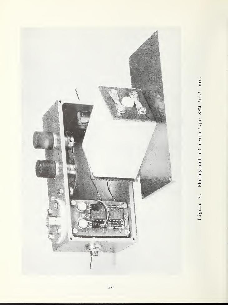
visual means. Therefore, a small test box was developed
which gives positive indication for burn-out of the 2 ohm
p-p fuse or either of the 2000 ohm p-c fuses. A selector
switch on the box allows a separate check for each mode and
burn-out is indicated when the appropriate red light glows.
39
The circuit is powered by 4 type A dry cells and can easily
be held in one hand. Use of the test box is simple and
straightforward and little operator instruction should be
required. A diagram of the circuit is shown in figure 6 and
a photograph of the prototype model is shown in figure 7.
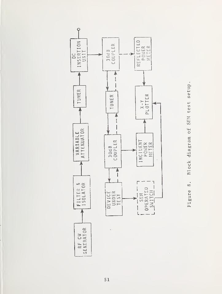
3. PERFORMNCE CHARACTERISTICS
Measurements to determine the rf performance charac-
teristics of the new SEM device were made using equipment as
shown in figure 8. The tuned reflectometer allows measure-
ment of the net power (P^) absorbed by the SEM to within
about 5 percent. The X-Y recorder is arranged to measure
incident power (P^) on the Y-axis and reflected power (P^)
on the X-axis. Net power is P = P. - P . The instant at^ n 1 r
which burn-out occurs is easily determined because the sudden
change in P^ causes the recorder trace to change slope
abruptly.
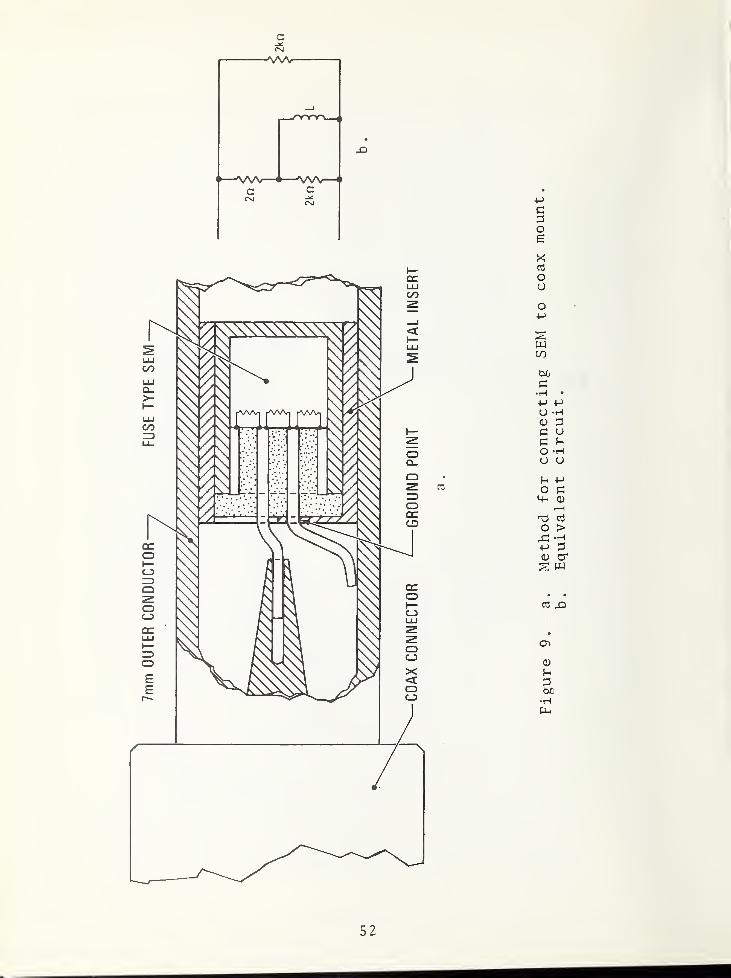
The coaxial mount used to hold the SEM during tests is
a special design employing a 7 mm coaxial line. Its
description and construction details are given in the companion
paper[l]. The mount is below resonance at frequencies up to
at least 10 GHz and, therefore, it does not absorb appreciable
power. In measuring the burn-out power of the 2 ohm p-p
fuses, it was necessary to connect one of the SEM leads to
ground in the 50 ohm, unbalanced, coaxial system as shown in
figure 9a. The ground lead in effect shorts one of the p-c
fuses for dc and low frequency signals, but not generally for
high rf and microwave frequencies. The equivalent circuit,
which should be valid from dc to fairly high frequencies, is
shown in figure 9b. The inductance, L, is due to the 7 mm
length of lead between the fuse and the point where the lead
is connected to the outer conductor. The resultant field
40

pattern inside the SEM is probably similar to some super-
position of the basic odd and even modes.
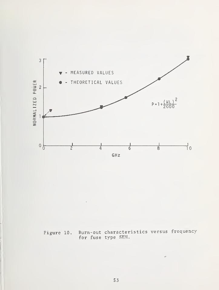
Earlier, it was mentioned that the burn-out power for
the 2 ohm p-p tin fuse was 25 to 30 mW. This is the burn-
out power when the 2 ohm fuse alone is mounted in the header.
When the two 2000 ohm p-c fuses are added, with the pin
connection as shown in figure 9, they absorb additional power.
This fact can be appreciated by referring again to figure 9b,
where it can be seen that at high frequencies, current in the
2 ohm leg of the circuit tends to flow through the 2K ohm
resistor rather than through L. The net result is that with
the addition of the p-c fuses, the net input power required
to burn-out the 2 ohm fuse increases with frequency. An
analysis of the equivalent circuit showed that 3 times as
much power is required to burn-out the 2 ohm fuse at about
10 GHz than at dc. Results of tests, shown in figure 10,
tended to verify this. Net power to the SEM required to
burn-out the 2 ohm p-p fuse was 30 mW at dc and increased to
90 mW at 10 GHz. This is a decided improvement over prior
SEM's where up to 800 mW of rf power is required for response
of the device. This loss in sensitivity is the price paid
for adding the capability to test for hazardous p-c voltages.
The degree to which the fuse-type SEM simulates the
electrical characteristics of typical EED ' s is considered
adequate. The 1 ohm resistance of EED bridgewires is
adequately simulated by the 2 ohm p-p fuse. While EED's
are open- circuited pins-to-case , the 2000 ohms resistance of
the p-c fuses in the SEM is not believed a critical degrading
compromise with respect to simulating an EED.
41
4 . SUMMARY
Presently available go, no-go type stray energy monitor
devices (SEM's) used for EED safety qualification testing are
relatively insensitive at rf and microwave frequencies and
do not provide monitoring for hazardous pins-to-case voltages.
A new SEM employing thin film fuses as the sensitive elements
has been developed at the National Bureau of Standards. The
pin-to-pin fuse burns out at 30 to 90 mW at frequencies from
dc to 10 GHz respectively. Also, pins-to-case monitoring
from each pin is provided at a threshold level of 10 V.
These sensitivities are believed adequate for testing of
hazards to accidental firing of 1 A, 1 W EED ' s in the two
modes described.
A small, hand-held test box was constructed which gives
positive indication of burn-out for any of the 3 fuses when
the SEM is connected to it after a test.
42
5. REFERENCES
Melquist, D.G., A.R. Ondrejka, and P. A. Hudson, An
evaluation of available stray energy monitors for
electroexplos ive device (EED) safety qualification,
presented at the 1973 IEEE International Symposium
on Electromagnetic Compatibility, New York, N.Y.,
June 1973.
Mason, B.A. , The use of tempilaq 45 in RF hazard
trials using the X2/H series of igniters, Royal
Armament Research and Development Establishment
Memorandum 36/64, p. 4, July 1964. (Cataloged by
DDC as AD No. 445156.)
Parker, Robert, A passive technique for measuring
high transient currents, Proc. 25th Annual ISA
Conference, Phil., Pa., pp. 720-1 thru 720-4,
Oct. 26-29, 1970.
43

44
Figure 2. Field configurations in two-conductorshielded transmission linea. Balanced (odd mode)b. Parallel (even mode)
45

Figure 3. Dimensions of thin film fuses.
46
Figure 4. Arrangement o£ fuses for attachmentpins-header assembly.
47
THIN FILM
INPUTLEAD
HEADER
Figure 5. Exploded view o£ complete SEM device.
48

1/1 t/) 1
—
c;ce o t c£ UJo Q 1
—
1
—
LU Q:: 1 o z UJ o \— 1 1 1
ct (_) o LOH- 3 o
IT) ct o C/1 >- uo c: 1— «UJ a: (_> o 1
—
1— X UJ encr: h- LU ct m Q o t/)
h- _l Q. 1— C\J Ci_ o UJ o1 cC o a; 1— O o o3 1— o 3. UJ 3 o Q_ I/) s:
a: 3 s: t/1 >- •a: 1
00 o uo o •a: et\ ir> 3 O •a: O XLU
h-UJ 1— (->
t/1BO
1— OO RO
h- UJ 1— LU UJ Q. oo «a: Q 1— Cl_O ct: >- Q. a: UJ D_<c 1— ct 1— Q H- O
Xo
p10
•M
wCO
p.
+->
opo
p.
mo
E
U00cti
•H
•P•H3O>H
•H
vD
(U
bO•HPh
49
50
c_) cs: I—1 1.
Q UJ ^ '
UJ O__i I—ca <
ct: UJ<C I—
oe5 O
oC/0
1—CJ UJ LUUJ i:: h-_J O UJu- Q_UJ
UJ1—
1
Xh-0_ia_
1—CC
UJ UJ UJ1—
0 UJQ_
2:1
—
i
QUJ
7n 1—1—UJ =3:1—
1
UJQ_ 000
01—
U- UJ
UJ0
c
t—vw-c
AA^/G
o6
X
ou
wCO
H
u<D
Pi
Ou u
5h 4->
O C
I—
I
o >
US
2 w
03 X)
(U
•H
52
53
BIBLIOGRAPHY
A. Instrumentation, Measurements, and Safety Qualification Testing
Development of RF Attenuator Utilizing Ferrite - CeramicComponents and the Effect of Nuclear Radiation on TheseComponents
Adelman, Stanley M. and Nancy B. Willoughby1969 Proc. EED Symposium (San Francisco, CA)1969, 4-8.1 thru 4-8.12
EBW Firing Unit - Detonator Compatibility TestsAmicone, Raymond G. and Michael G. Kelly
1969 Proc. EED Symposium (San Francisco, CA)1969, 4-13.1 thru 4-13.13
Test Equipment for and Evaluation of Electromagnetic Radiation(Includes Appendix A: "Texaco Thermistor Tests and Results")
Amme , R. C, D. E. Rugg, J. E. Nunnally and J. G. HewittU. S. Navy Contract N12 3 ( 60 530 ) 100 49A (U. Denver ResearchInstitute- Supplementary Final Report)Mar. 31, 1961, 78 pages
RF Susceptibility of the Titan III Ordnance Devices, Revision AAsiala, G. , J. Barry, W. Lillie, G. Lover, J. Kilma, D. Roark,D. Robertson, E. Visser and M. Weidman
Martin Co. Denver, CO (Contract No. AF04 (695) -150)January 1965, 183 pages
Circuit for Studying the Electrostatic Sensitivity ofElectroexplosive Devices (Schaltung zur Untersuchung derelektros tatischen Empfindlichkeit von elektroexplosiven Elementen)
Austing, James L. and Richard GortowskiExplosivstof f
e
Feb. 1971, Vol. 19, No. 2, 39-43 (In English)
Fast-Rise High-Current Constant Current Firing Circuit forElectroexplosive Devices
Austing, James L. and Arthur L. UsherProc. 7th Symposium on Explosives & Pyrotechnics(Phila. , PA)1971, II-2-1 thru II-2-5
A Low-Frequency Thermal Follow Bridge for Measuring the Electro-Thermal Parameters of Bridgewires
Ayres , James N., Louis A. Rosenthal and Richard A. MaioU.S. Naval Ordnance LaboratoryNOLTR 66-113Mar. 17, 1967, approx. 40 pages
54
The Outlook for Nondestructive Electrothermal ParametricMeasurements on Wire-Bridge EED's
Ayres , J. N., C. W. Goode , I. Kabik and L. A. Rosenthal1967 Proceedings EED Symposium (Phila. , PA, June 13-14)1967, 4-1.1 thru 4-1.22
Some Initial Investigations of the Laser Initiation of ExplosivesBarbarisi, Modesto J. and Edward G. Kessler
1969 Proc. EED Symposium (San Francisco, CA)1969, 4-1.1 thru 4-1.19
Research and Development Leading to Perfection of Ins trumenationof Electroexplosive Devices
Barker, D. B., R. K. Fry, T. N. Grigsby , J. E. Nunnally,D. E. Rugg and G. Wolff
U. of Denver, Denver Research InstituteDec. 31, 1961, Quarterly Report No. 3, (N178-7818) 67 pages
Research and Development Leading to Perfection of Ins trumenationof Electro-Explosive Devices, Volume II
Barker, D. B., R. K. Fry, T. N. Grigsby, J. E. Nunnally,D. E. Rugg and G. Wolff
U. of Denver, Denver Research InstituteMar. 31, 1962, Final Report, (N178-7818) 89 pages
A Study of the Simulation of Instrumented to Loaded EED'sBarker, D. Boyd and Richard K. Fry
1963 Proc. 2nd HERO Congress (Franklin Institute,Phila. PA, USA)1963, 47-1 thru 47-11
Radio-Frequency E-Field SensorBarnes, J. C.
Development Report SC-DR-71 0219(Sandia Laboratories)July 19 71, 31 pages
Predicted and Measured Power Density Description of a LargeGround Microwave System
Bathker, D. A.NASA Technical Memorandum 33-433(Jet Propulsion Laboratory)Apr. 15, 1971, 34 pages
Comments Relating to Confidence-Reliability Combinations forSmall-Sample Tests of Aerospace Ordnance Items
Benedict, A. G.1967 Proceedings EED Sym.posium (Phila. , PA, June 13-14)1967, 4-6.1 thru 4-6 .9
55

Electrical Protection Guide for Land-Based Radio FacilitiesBodle, David
Joslyn Electronic Systems, Santa Barbara Research ParkP. O. Box 817, Goleta, CA 93017June 1971, 67 pages
The Design of Sterilizable Pyrotechnic DevicesBowman, N. J. and E. F. Knippenberg
1967 Proceedings EED Symposium (Phila. , PA, June 13-14)1967, 4-3.1 thru 4-3.15
Remote Initiation with Non-Coherent LightBratton, Francis H.
Proc. 7th Symposium on Explosives & Pyrotechnics(Phila., PA)1971, 1-8-1 thru 1-8-5
RF Susceptibility Analysis and Proposed RF Susceptibility TestPlan for the Manufacturing Phase of EM-5 Rocket Motor IgniterAssemb ly
Brewington, Curtis E., Joseph Jacobs and Abraham GrinochPicatinny Arsenal Tech. Memorandum 1772Dec. 1965, 36 pages
Precision Measurement of Detonation Velocities in Liquid andSolid Explosives
Campbell, A. W. , M. E. Malin, T. J. Boyd, Jr., and J. A. HullReview Scientific InstrumentsAug. 1956, Vol. 27, No. 8, 567-574
Electrical Impedance of the Human Body for HF (2-30 MHz) Band(Initial Results)
Carson, R. W. and W. E. InnisU.S. Naval Weapons Laboratory Tech. Report TR-24 81Oct. 1970, 83 pages
The Safety of EEDs in the Naval Electromagnetic EnvironmentChesterman, F. J.
1969 Proc. EED Symposium (San Francisco, CA)1969, 3-1.1 thru 3-1.12
Present Status of HERO InstrumentationConnelly, Marion P., Jr.
Naval Weapons Laboratory Tech. Report TR-229 5
May 1969, 19 pages
The Lightning Arrestor-Connector — A New Concept in SystemElectrical Protection
Cooper, J. Arlin and Leland J. Allen1972 IEEE International EMC Symposium RecordIEEE 72 CH06 38-7 EMCJuly 1972, 194-199
56

Vacuum Deposited Thin Film Bridges in Electroexplosive DevicesCraig, J. R. , O. M. Schroll, C. E. Simpson and R. Blackshire
1969 Proc. EED Symposium (San Francisco, CA)1969, 1-6.1 thru 1-6.12
Instrumentation for Research, Evaluation and Quality Controlof Electroexplosive Initiators
Davey, C. T., W. S. Weiss and W. J. Dunning1967 Proceedings EED Symposium (Phila., PA, June 13-14)1967, 4-5.1 thru 4-5.12
Minuteman HERO TestingDoellner, Leonard
Proc. 7th Symposium on Explosives & Pyrotechnics(Phila. , PA)1971, II-8-1 thru II-8-8
The Theory of Induced Electrical Transients in UnscreenedAircraft Armament Wiring
Drysdale, H.Royal Aircraft Establishment, Ministry of Aviation, LondonTechnical Note No. WE. 28Jan. 1964, 70 pages
HERO Supporting StudiesFaunce, Norman P. and Paul F. Mohrbach
The Franklin Institute for U.S. Naval Weapons LaboratoryAug. 1 to Aug. 31, 1962, (N178-8102) , 15 pages
HERO Supporting StudiesFaunce, Norman P. and Paul F. Mohrbach
The Franklin Institute for U.S. Naval Weapons LaboratorySept. 1 to Sept. 30, 1962, (N178-8102) , approx . 40 pages
HERO Supporting StudiesFaunce, Norman P. and Paul F. Mohrbach
Progress Report P-B19 80-10 (Franklin Institute Labs. R/D)(U.S. Naval Weapons Lab. Contract No. N178-8102)Apr. 1963, 13 pages
HERO Supporting StudiesFaunce, Norman P. and Paul F. Mohrbach
Technical Report F-B1980 (Franklin Institute Labs. R/D)(U.S. Naval Weapons Lab. Contract No. N178-81Q2)Sept. 30, 1963, 69 pages
A Jet-Edge Oscillator for Sensing Electrical CurrentsFine, Jonathan E.
U.S. Army Materiel Command, Harry Diamond LaboratoriesOct. 1970, 24 pages
57
Verification of the Apollo Standard Initiator with Respect toRadio Frequency Radiation Hazards
Fredrickson, R. L., A. Woronow, M. E. Alvarez,R. F. D'Ausilio, P. J. Berndsen, C. N. Child, J. W. Haffnerand W. J. Coleman
North American Aviation, Inc. (Contract NAS9-150, CCA 412)SID 67-333Mar. 1967, 57 pages
An Application of a Thermal Explosion Criterion to the Initiationof Explosives by Rapidly Heated Wires
Friedman, M. H. and R. L. McCally1967 Proceedings EED Symposium (Phila., PA, June 13-14)1967, 3-11.1 thru 3-11.11
Near Field Coupling to Aircraft in the 1-30 MHz BandGray, R. I.
1968 IEEE Electromagnetic Compatibility Symposium RecordSeattle, WA (IEEE: New York USA)1968, 253-261
A Microcircuit Bridge for High-Reliability Electro-ExplosiveDevices
Griffin, D. N.1967 Proceedings EED Symposium (Phila., PA, June 13-14)1967, 3-5.1 thru 3-5.25
Further Advances in Microcircuit Bridge TechnologyGriffin, D. N.
1969 Proc. EED Symposium (San Francisco, CA)1969, 1-11.1 thru 1-11.12
HERO Testing: Techniques and ProceduresGrove, Richard E.
U.S. Naval Weapons Laboratory Tech. MemorandumSept. 1960, 21 pages
Nondestructive Measurement of the Quality of ElectroexplosiveInterfaces
Harwood, W. D. and L. G. StewartMaterials EvaluationDec. 1968, Vol. 26, 254-256, 260
Time Domain Reflectometry in Reliability TestingHewett, L. L. and J. R. Petri ck
1966 Annual Symposium Reliability (IEEE, InstituteEnvironmental Sciences, Society Nondestructive Testing& American Society Quality Control) San Francisco, CAJan. 1966, 409-418
58
Radio Frequency Instrumentation AmplifierHewitt, Jack G., Jr.
Sandia P. O. 73-2948 (Final Report, U. Denver ResearchInstitute)Sept. 15, 1967, 55 pages
Instrumentation for Making Broadband Measurements on Electro-explosive Devices
Hewitt, Jack G., Jr.6th EED Symposium, San Francisco CA (Denver Research Inst.)1969 , 3-11. 1— 3-11. 17
A Method for Meeting the Ordnance Susceptibility TestRequirements of MIL-E-60 51D
Hewitt, Jack G. , Jr. and Wesley R. Johnson19 72 IEEE International EMC Symposium RecordIEEE 72 CH0638-7EMCJuly 1972, 50-55
Instrument Techniques for Monitoring Electrical TransientsHoltman, R. F. and L. W. Olson
Air Force Avionics LaboratoryTechnical Report AFAL-TR-6 8-29
7
Dec. 1968, 138 pages
The Initiation of Electric Fuze Primers by ElectrostaticDischarge
Kabik, I. and J. N. AyresNAVORD Report 176 2 (U.S. Naval Ordnance Lab.)Jan. 18, 1951, 11 pages
A Mathematical Analysis of Ordnance Circuitry to Determinethe Susceptibility to Stray RF Fields
Klima, Jon E.1967 Proceedings EED Symposium (Phila., PA, June 13-14)1967, 4-9 .1 thru 4-9 .29
Nondestructive Testing of Apollo CSM Spacecraft Ordnance Devicesby Neutron Radiography
Knight, W. H., A. L. Kitchens, N. M. Ewbank and G. Gigas1969 Proc. EED Symposium (San Francisco, CA)1969, 2-11.1 thru 2-11.16
A Reliability Test Method for "One-Shot" ItemsLanglie, H. J.
U.S. Army Contract DA-04-495-ORD-1835 (Aeronutronic Div.Ford Motor Co. , Newport Beach, CA)Publication No. U-1792Aug. 10, 1962, 70 pages
59
Fabrication of Vacuum Deposited Thermocouples and AssociatedElectro-Explosive Device Simulators
Larsh , W. N.U.S. Naval Weapons Laboratory Tech. MemorandumMar. 1961, 8 pages
A New Technique for Detecting the Initial Reaction of PrimaryExplosives Initiated by Hot Wire
Leopold, Howard S.U.S. Naval Ordnance LaboratoryNov. 7, 1969, 21 pages
Recent Observations on the Hot Wire Initiation of PrimaryExplosives
Leopold, Howard S.Proc. 7th Symposium on Explosives & Pyrotechnics(Phila. , PA)1971, I-l-l thru 1-1-4
Laser Energized Explosive Device SystemLewis, Donald J.
1967 Proc. EED Symposium (Phila. , PA)1967, 2-8.1 thru 1-8.22
Scattering of Electromagnetic Radiation by Apertures; I. NormalIncidence on the Slotted Plane
Libelo, L. F. and J. BombardtNOLTR 70-5 8 (U.S. Naval Ordnance Lab.)Apr. 2, 1970, 46 pages
Scattering of Electromagnetic Radiation by Apertures; II.Oblique Incidence on the Slotted Plane for Parallel Polarization
Libelo, L. F. and J. BombardtNOLTR-72-25 (U.S. Naval Ordnance Lab.)Jan. 15, 1972, 39 pages
The Use of Tempilaq 45 in R.F. Hazard Trials Using the X2/HSeries of Igniters
Mason, B. A.R.A.R.D.E. Memorandum 36/64 (United Kingdom)July 196 4, approx. 20 pages
Comparative Effects of CW and Radar Signals on EED BridgewireTemperature
Mayes, O. W. and Charles Carlson19 69 Proc. EED Symposium (San Fancisco, CA)1969, 4-12.1 thru 4-12.15
60
Adaptation of Fault Tree to the Safety Analysis of PyrotechnicDevices
McClay, R. E. and M. M. HoobchaakProc. 7th. Symposium on Explosives & Pyrotechnics(Phila. , PA)1971, 1-7-1 thru 1-7-10
Direct Laser Initiation of Insensitive ExplosivesMenichelli, Vincent J. and L. C. Yang
Proc. 7th Symposium on Explosives & Pyrotechnics(Phila. , PA)1971, III-2-1 thru III-2-8
Interrelationship of Nondestructive Testing to FaultDetermination
Menichelli, Vincent J. and Louis A. RosenthalProc. 7th Symposium on Explosives & Pyrotechnics(Phila. , PA)1971, II-5-1 thru II-5-7
Fault Determinations in Electroexplosive Devices byNondestructive Techniques
Menichelli, Vincent J. and Louis A. RosenthalNASA Technical Report 32-1553 (Jet Propulsion Lab.)Mar. 15, 1972, 18 pages
Initiation of Insensitive Explosives by Laser EnergyMenichelli, Vincent J. and Lein C. Yang
JPL Technical Report 32-1557June 1, 19 72, 23 pages
Special Radio Frequency Tests on Apollo Standard Initiator(Task No. 4)
Mohrbach, Paul F., Robert F. Wood and Victor W. GoldieTech. Report F-B230 3-4 (Franklin Institute Research Lab.)(Final Report, Contract No. NAS-9-3787-4 for NASA)Apr. 196 6, 50 pages
Effects of Radio Frequency Stimuli on Electroexplosive DevicesMohrbach, Paul F. and Robert F. Wood
196 7 Proceedings EED Symposium (Phila. , PA, June 13-14)1967, 2-9.1 thru 2-9.8
RF Evaluations of the Stray Electrical Energy Indicator (SEEI)Mohrbach, P. F. and R. R. Raksnis
Tech. Report F-C2142 (Franklin Institute Research Lab.)(Final Report, Contract No. NAS9-7601 for NASA)Jan. 1968, 15 pages
61
Monograph on Computation of RF HazardsMohrbach, Paul F. , Ramie Thompson, Robert F. Wood andDaniel J. Mullen
Franklin Institute Research LaboratoriesPrepared for: NASA, Goddard Space Flight CenterJuly 1968, 70 pages
Development of An Ordnance Circuit RF FilterMohrbach, P. F. and D. J. Mullen
1969 Proc. FED Symposium (San Francisco, CA)1969, 1-12.1 thru 1-12.13
Determining Ratings of RF Suppression DevicesMohrbach, P. F., R. F. Wood and R. H. Thompson
1969 Proc. FED Symposium (San Francisco, CA)1969, 4-14.1 thru 4-14.17
The Development of a Fixed Gap Electrostatic Spark DischargeApparatus for Characterizing Explosives
Montesi, Louis J.1969 Proc. EED Symposium (San Francisco, CA)1969, 2-8.1 thru 2-8.15
Determination of Responses of Protected and Unprotected ElectricInitiators to Electrical Stimuli: Special Technical Report onMetavac, Incorporated Ferrite-Ceramic RF Attenuator ProtectiveDevice
Musil, V. P.U.S. Naval Weapons Laboratory(Research & Development Project conducted by Genistron,Inc., Los Angeles, CA) Report No. 2400-5754-3Feb. 26, 1965, (N178-8290) 85 pages
Initiation of Electroexplosive Devices by LightningNorth, H. S.
19 69 Proc. EED Symposium (San Francisco, CA)1969, 3-8.1 thru 3-8.6
A Passive Technique for Measuring High Transient CurrentsParker, Robert
Proc. 25th Annual ISA Conference (Phila. , PA)Advances in Instrumentation1970, Vol. 25, Pt. 3, 720-1 thru 720-4
Problems in Sensitivity Testing of "One Shot" Electro-ExplosiveDevices
Peckham, Herbert D.(19 6 5 Aerospace Conference Proceedings)IEEE Trans. Aerospace (Supplement)June 1965, Vol. AS-3, No. 2, 628-633
62

Experimental Distribution of Bruceton Test StatisticsPeckham, Herbert D.
1967 Proceedings EED Symposium (Phila. , PA, June 13-14)1967, 4-10.1 thru 4-10.12
ELectromagnetic Compatibility Analysis of the 0 A 0 FairingElectro-Explosive Circuitry
Pelland, P. L.General Dynamics/Convair for NASA/LeRCReport No. ZZK-65-0191965, 55 pages
Electro-Explosive Device Pulse Reflection Checkout TechniquePetrick, J. R.
(1965 Aerospace Conference Proceedings)IEEE Trans. Aerospace (Supplement)June 1965, Vol. AS-3, No. 2, 634-637
Recent Developments in Modeling the Hotwire IgniterPetrick, John T. and Robert L. Montgomery
Proc. 7th Symposium on Explosives & Pyrotechnics(Phila. , PA)1971, 1-4-1 thru 1-4-6
Experiments in the Protection of EED's from ElectrostaticDischarge
Pierson, Edward G.19 69 Proc. EED Symposium (San Francisco, CA)1969, 3-6.1 thru 3-6.11
Measurement of Induced Electrical Transients in AircraftArmament Wiring
Rams ay , A . A
.
Royal Aircraft Establishment, Ministry of Aviation, LondonTechnical Note No. WE. 30Jan. 1964, 64 pages
Lightning Surge Current Hazards to Semi-Conductors andElectroexplosive Systems
Robb, J. D. and J. R. Stahmann1967 Proceedings EED Symposium (Phila.., PA, June 13-14)1967, 2-4.1 thru 2-4.16
Radiofrequency-Interference Protection for Pyrotechnic Systemsin Manned Spacecraft
Robinson, Robert L.1967 Proceedings EED Symposium (Phila., PA, June 13-14)1967, 2-2.1 thru 2-2.14
63
Preliminary Report on the Effect of Radio-Frequency Energy onElectric Squibs
Rodgers , EricU. Alabama, Physics Dept., Tech. Report No. 1
Dec. 15, 1952, 16 pages
Electro-Thermal Equations for Electro-Explosive Devices (U)Rosenthal, Louis A.
U.S. Naval Ordnance Lab., NAVORD Report 6684Aug. 15, 19 59, 4 8 pages
The Harmonic Generation Technique for the Determination ofThermal Characteristics of Wire Bridges Used in Electro-Explosive Devices (U)
Rosenthal, Louis A.NAVORD Report 6691Sept. 9, 1959, 21 pages
Generator Delivers Constant Current or Voltage PulsesRosenthal, Louis A.
ElectronicsSept. 16, 1960, Vol. 33, No. 28, 82-84
A Cooling Curve Generator and Its Application to Electro-Explosive Device Studies (U)
Rosenthal, Louis A.NAVWEPS Report 7313Dec. 15, 1960, 17 pages
Thermal Response of Bridgewires Used in Electroexplosive DevicesRosenthal, Louis A.
Review Scientific InstrumentsSept. 1961, Vol. 32, No. 9, 1033-1036
Electrothermal Measurements of Bridgewires Used in Electro-explosive Devices
Rosenthal, Louis A.IEEE Trans. Instrumentation & MeasurementJune 1963, Vol. IM-12, No. 1, 17-21
Nonlinear Bridge for Electrotheimal MeasurementsRosenthal, Louis A.
Review Scientific InstrumentsAug. 1965, Vol. 36, No. 8, 1179-1182
Millisecond Switch for Electroexplosive TestingRosenthal, Louis A.
IEEE Trans. Instrumentation & MeasurementMar. 1969, Vol. IM-18, No. 1, 19-22
64

Thermal Conductance Measurement in Electroexplosive Devices bySelf-Balancing Bridge Techniques
Rosenthal, Louis A.Review Scientific InstrumentsMar. 1971, Vol. 42, No. 3, 321-326
Fiber Optics in Explosive Functioning-Time MeasurementRosenthal, Louis A.
IEEE Trans. Instrumentation & MeasurementAug. 1971, Vol. IM-20, No. 3, 154-158
Terminated Capacitor-Discharge Firing of Electroexplosive DevicesRosenthal, Louis A. and V. J. Menichelli
IEEE Trans. Instrumentation & MeasurementMay 1972, Vol. IM-21, No. 2, 177-180
Screening at V.H.F. — Efficacy of Metallic SurfacesRoston, B.
Wireless EngineerJuly 1948, Vol. 25, No. 298, 221-230
Energy Transfer in Electrostatic ArcsSchroeder, C. F. , Jr.
1967 Proceedings EED Symposium (Phila., PA, June 13-14)1967, 2-5.1 thru 2-5.10
A Method of Measuring the Relative Intensity of ElectromagneticEnvironments with Respect to HERO
Schwab, Helmut A. and Roger W. CarsonU.S. Naval Weapons Laboratory Tech. Report TR-217 7
June 19 68, 3 8 pages
RF Protection in Electro-Explosive Devices Through the Use ofR-L-C Networks
Sidoti, Joseph E.1967 Proceedings EED Symposium (Phila., PA, June 13-14)1967, 2-8.1 thru 2-8.7
A Method for Calibrating Video Detector InstrumentedElectroexplosive Devices for Use in Electromagnetic RadiationTesting
Sons, Richard J.Technical Memorandum SC-TM-6 8-2 73 (Sandia Laboratory)June 19 68, 33 pages
Safety Certification of New Pyrotechnic DevicesSullivan, T. J. and Mrs. J. A. McDevitt
Proc. 7th Symposium on Explosives & Pyrotechnics(Phila., PA)1971, III-6-1 thru III-6-8
65
Electrostatic-Insensitive Detonator for Precise SynchronizationTaylor, Boyd C.
1969 Proc. EED Symposium (San Francisco, CA)1969, 1-10.1 thru 1-10.13
Short Pulse TestingThompson, R. H. and V. Goldie
Proc. 7th Symposium on Explosives & Pyrotechnics(Phila. , PA)1971, II-6-1 thru II-6-12
Explosive Actuation — Fast - Powerful - ReliableThrogmorton, T. J.
Control EngineeringAug. 1962, Vol. 9, No. 8, 71-74
Evaluation of an Automated Electrical Transient Monitorfor Field Use
Tomlinson, Kenneth W. and Edward W. TaylorAir Force Avionics LaboratoryTechnical Report AFAL-TR-70 -110Aug. 1970, 44 pages
Stray Energy TesterVan Allen, John and Franklin E. White
U.S. Air Force Special Weapons Center, Kirkland, NMAF Contract 29 (601) -2843 (U. of Denver)July 15, 1961, 106 pages
A Broadband RF Filter/Attenuator Plug for Wire Bridge Electro-Explosive Devices (EED's)
Warshall, Theodore and Paul F. Mohrbach1969 Proc. EED Symposium (San Francisco, CA)1969, 3-2.1 thru 3-2.12
The EMI Hazard Measuring SystemWatton, William L. , Malcolm G. Brown and William B. Scamaton
1969 Proc. EED Symposium (San Francisco, CA)1969, 3-4.1 thru 3-4.17
Use of Neutron Radiography for Visual Non-Destructive Examinationof Ordnance Components
Wilson, Cr. R. and W. B. Breakey1969 Proc. EED Symposium (San Francisco, CA)1969, 2-10.1 thru 2-10.13
Characterization of the MK 1 MOD O Squib - ImpedanceMeasurements in the Frequency Range 50 - 150 0 Megacycles (U)
Wyatt, R. M. H.NAVORD Report 6 826May 31, 1960, 31 pages
66
Technical Manual: Air Force Communications Service (E-1 Standard)Electromagnetic Radiation Hazards
Change 2, T.O. 31Z-10-4June 1, 1971, 161 pages
Design Handbook Series 1-0 General—Electromagnetic Compatibility
AFSC DH 1-4Jan. 10, 1972, approx. 75 pages
Engineering Design Handbook - Hardening Weapon Systems AgainstRF Energy
U.S. Army Materiel Command, AMCP 706-235Feb. 19 72, approx. 220 pages
Plastic Materials Reduce P-Static Interference in AircraftCommunications
Communications Designer's DigestApr. 1969, Vol. 3, No. 4, 38, 40
Antennas, Transmission Lines Major Influence on RadiatedInterference in Receivers
Communications Designer's DigestSept. 1968, Vol. 2, No. 9, 34-35
Technique Cuts Repeatability Errors of Shielded-Room FieldStrength Measurements
Communications Designer's DigestSept. 1968, Vol. 2, No. 9, 35-38
Binomial Wave Synthesis Proposed for Data Pulses to CutBroad-Band EMI
Communications Designer's DigestNov. 1968, Vol. 2, No. 11, 30-31
Model Predicts Effect of Pigtail Terminations on InterferenceTests
Communications Designer's DigestOct. 1969, Vol. 3, No. 10, 45-47
67
Models Predict Effect of Pulse Parameters on Radar EmmissionSpectra
Communications Designer's DigestDec. 1969, Vol. 3, No. 12, 34, 36-38
Measurement Tool Gauges Effectiveness of Cable Shielding to300 MHz
Communications Designer's DigestJan. 1970, Vol. 4, No. 1, 17-19
EMC Measurements Aim at Characterizing Cable InterferenceParameters
Communications Designer's DigestJan. -Feb. 1971, 54-56
Computer-Derived Tables Solve EMI Shielding Equations in Minutes
Communications Designer's DigestJuly-Aug. 1971, 37-40
Radio Frequency Energy--A Potential Hazard in the Use andTransportation of Electric Blasting Caps
The Explosives EngineerJuly-Aug. 1953, Vol. 31, No. 4, 116-117
Summary and Project Briefing Supplement: Project 5610,Task 01 Briefing
Los Alamos Scientific LaboratoryMar. 15, 1972, 48 pages
Electroexplosives Safety Qualifications
ASD/ENVCC Project 5610 (Los Alamos Scientific Laboratoryunder AEC Contract W-7405-Eng. 36)Mar. 15, 1972, 75 pages
R&D Contract Status Report forEvaluation of Electroexplosive Device (EED)Response to Electromagnetic Radiation (EMR)
Project 5610, Task 01 (Los Alamos Scientific Laboratoryunder AEC Contract W-7405-ENG-36)Mar. 1 to Apr. 30, 19 72, 60 pages
68
Operation and Maintenance Manual - Model 560 Series Oscillograph
Midwestern Instruments1962, approx. 20 pages
Power Densities at Apollo/Saturn Assembly and Launch Complexesas a Result of High Power RF Emitters
Kennedy Space Center TR-5 6 3 (NASA)Sept. 15, 1967, approx. 50 pages
Low Band Pass Transformer
Daystrom, Weston Instruments Div. , for Naval WeaponsLaboratory, Dahlgren, VA, Contract No. N178-8080Tech. Progress Report, Phase I
July 1, 1962, to Oct. 31, 1962, 41 pages
Design Principles and Practices for Controlling Hazards ofElectromagnetic Radiation to Ordnance (HERO Design Guide)
NAVWEPS OD 30 393June 15, 1965, 100 pages
Determination of Responses of Protected and Unprotected ElectricInitiators to Electrical Stimuli — Special Technical Report onTheory, Parameters and Measurement Methods
U.S. Naval Weapons Laboratory(Research & Development Project conducted by Genistron,Inc., Los Angeles, CA) Report No. 2400-5754-1June 4, 1965, (N178-8290) 77 pages
LEED Systems (Laser Energized Explosive Device)
Space Ordnance Systems, Inc., Technical Report 6221Mar. 1, 1968, 67 pages
Military Specification: Bonding, Electrical, and LightningProtection, for Aerospace Systems
MIL-B-50 87B (ASG)Oct. 15, 196 4/ approx. 30 pages
Military Specification: Bonding, Electrical, and LightningProtection, for Aerospace Systems
MIL-B-50 87B(ASG) - Amendment 2
Aug. 31, 19 70, 4 pages
69

Military Specification: Electronic Equipment, Airborne/General Specification for
MIL-E-5400NNov. 30, 19 71, approx. 50 pages
Military Specification: Electromagnetic CompatibilityRequirements, Systems
MIL-E-6051DSept. 7, 1967, approx. 20 pages
Military Specification: Interim Amendment - ElectromagneticCompatibility Requirements, System
MIL-E-60 51D - Amendment 1 (USAF)July 5, 196 8, 1 page
Military Specification: Electronic Equipment, Aerospace,Extended Space Environment, General Specification for
MIL-E-8983ANov. 30, 1971, 29 pages
Military Specification: Interference Control Requirements,Aircraft Equipment
MIL-I-6181DNov. 25, 1959, 31 pages
Military Specification: Interference Control RequirementsAircraft Equipment
MIL-I-6181D - Notice 6
July 24, 1969, 1 page
Military Specification: Preclusion of Hazards fromElectromagnetic Radiation to Ordnance, General Requirements for
MIL-P-24014 (WEP)Jan. 30, 1964, 10 pages
Military Specification: Preclusion of Hazards from Electro-magnetic Radiation to Ordnance, General Requirements for
MIL-P-24014 (WEP) - Amendment 3
Sept. 22, 1965, 7 pages
70
Military Standard: Test Methods for Electronic and ElectricalComponent Parts
MIL-STD-202DApr. 14, 1969, approx. 200 pages
Military Standard: Test Methods for Electronic and ElectricalComponent Parts
MIL-STD-20 2D - Notice 1
Apr. 15, 19 70, 6 pages
Military Standard: Method of Insertion-Loss Measurement
MIL-STD-220ADec. 15, 1959, 25 pages
Military Standard: Fuze and Fuze Components, Environmental andPerformance Tests for
MIL-STD-331Jan. 10, 1966, approx.
Military Standard: Fuze andPerformance Tests for
MIL-STD-331 - Change Notice 1
July 24, 1967, 56 pages
Military Standard: Fuze and Fuze Components, Environmental andPerformance Tests for
MIL-STD-331 - Change Notice 2
Dec. 11, 1967, 8 pages
Military Standard: Fuze and Fuze Components, Environmental andPerformance Tests for
MIL-STD 331 - Notice 3
June 11, 1969, 38 pages
Military Standard: Fuze and Fuze Components, Environmental andPerformance Tests for
MIL-STD-331 - Notice 4
Apr. 16, 19 71, 10 pages
300 pages
Fuze Components , Environmental and
71

Military Standard: Fuze and Fuze Components, Environmental andPerformance Tests for
MIL-STD-331 - Notice 5
June 1, 19 71, 14 pages
Military Standard: Inspection, Radiographic
MIL-STD-453Oct. 29, 1962, 5 pages
Military Standard: Inspection, Radiographic
MIL-STD-453 - Change Notice 1
Sept. 4, 1963, 6 pages
Military Standard: Electromagnetic Interference CharacteristicsRequirements for Equipment
MIL-STD-461AAug. 1, 196 8, 74 pages
Military Standard: Electromagnetic Interference CharacteristicsRequirements for Equipment
MIL-STD-461A - Notice 1
Feb. 7, 1969, 15 pages
Military Standard: Electromagnetic Interference CharacteristicsRequirements for Equipment
MIL-STD-461A - Notice 2
Mar. 20 , 1969 , 1 page
Military Standard: Electromagnetic Interference CharacteristicsRequirements for Equipment
MIL-STD-461A(USAF) - Notice 3
May 1, 1970, 13 pages
Military Standard: Electromagnetic Interference CharacteristicsRequirements for Equipment, Subsystem and System
MIL-STD-461A - Notice 4 (EL)Feb. 9, 19 71, 70 pages
72
Military Standard: Electromagnetic Interference Characteristics,Measurement of
MIL-STD-462July 31, 1967, 94 pages
Military Standard: Electromagnetic Interference Characteristics,Measurement of
MIL-STD-462 - Notice 1
Aug. 1, 196 8, 6 pages
Military Standard: Electromagnetic Interference Characteristics,Measurement of
MIL-STD-462 (USAF) - Notice 2
May 1, 19 70, 8 pages
Military Standard: Electromagnetic Interference Characteristics,Measurement of
MIL-STD-462 - Notice 3 (EL)
Feb. 9, 1971, 137 pages
Military Standard: Environmental Test Methods
MIL-STD-810B (USAF)June 15, 1967, approx . 125 pages
Military Standard: Environmental Test Methods
MIL-STD-810B (Notice - 1) (USAF)Oct. 20, 1969, 68 pages
Military Standard: Environmental Test Methods
MIL-STD-810B (Notice - 2) (USAF)Sept. 29, 1969, 17 pages
Military Standard: Environmental Test Methods
MIL-STD-810B (Notice - 3) (USAF)Sept. 18, 1970, 18 pages
Military Standard: Environmental Test Methods
MIL-STD-810B (Notice - 4) (USAF)Sept. 21, 1970, 8 pages
73
Military Standard: Electromagnetic Interference Test Requirementsand Test Methods
MIL-STD-826A(USAF)June 30, 1966/ 114 pages
Military Standard: Electromagnetic Interference TestRequirements and Test Methods
MIL-STD-826A(USAF) - Notice 1
July 10, 1967, 8 pages
Military Standard: Electromagnetic Interference TestRequirements and Test Methods
MIL-STD-826A(USAF) - Notice 3
Jan. 25, 1968, 1 page
Military Standard: Effectiveness of Cable, Connector, andWeapon Enclosure Shielding and Filters in Precluding Hazards ofElectromagnetic Radiation to Ordnance; Measurement of
MIL-STD-1377 (Navy)Aug. 20, 1971, 29 pages
B. Basic Characteristics of EED's
On the Minimum Ignition Energy of the Electric DetonatorAkazaki, M. and S. Hokari
J. of Inst. Elec. Engrs . JapanMar. 1960, Vol. 80, No. 858, 349-354 (Japanese)
A Heat Transfer Study of Hot Wire Ignition of a Metal-MetalOxide Mixture
Austing, J. L., J. E. Kennedy, D. H. Chamberlain andR. H. Stresau
1967 Proceedings FED Symposium (Phila. , PA, June 13-14)1967, 3-8.1 thru 3-8.24
Properties and Performance of Aluminum-Plated Pyrotechnics forElectroexplosive Device Applications
Austing, James L. and Robert F. RemalyProc. 7th Symposium on Explosives & Pyrotechnics(Phila. , PA)1971, III-5-1 thru III-5-12
Development and Functional Characteristics of the XM8 SquibBetts , R. E. and W. P. Williams
Report No. RK-TR-62-6 (U.S. Army Missile Command)Oct. 26, 1962, 33 pages
74
Detached Electrode Electroexplosive DevicesChamberlain D. H. and R. H. Stresau
19 69 Proc. EED Symposium (San Francisco, CA)1969, 1-8.1 thru 1-8.22
Response of Atlas Type F Squibs to Very Short PulsesCharlton, A. Lloyd
Picatinny Arsenal Tech. Memorandum 20 24Sept. 1971, 26 pages
Numerical Thermal Analysis of Electro-Explosive DeviceDansby, H. Bishop and William B. Freeman
Proc. 7th Symposium on Explosives & Pyrotechnics(Phila. , PA)1971, 1-2-1 thru 1-2-6
Temperature Coefficient of Resistivity Effects on lA/lWNo-Fire Initiators
Davenport, D. E.1967 Proceedings EED Symposium (Phila. , PA, June 13-14)1967, 3-1.1 thru 3-1.19
Quantitative Predictions of EED Firing CharacteristicsDavenport, D. E. and Herbert Reynolds
1969 Proc. EED Symposium (San Francisco, CA)
1969, 2-6.1 thru 2-6.24
The Development of a Solid State Explosive InitiatorFlagg, Robert F., Ernest J. Stecker andLewis E. Hollander, Jr.
1969 Proc. EED Symposium (San Francisco, CA)1969, 4-2.1 thru 4-2.16
Liquid Desensitized InitiatorsHeinemann, Robert W.
1969 Proc. EED Symposium (San Francisco, CA)
1969, 3-10.1 thru 3-10.6
Characterization of Squib MK 1 MOD 0; Sensitivity to 9KMC RadarPulses
Kabik , I. and C. GoodeU.S. Naval Ordnance Lab.NOLTR 2 6-77Aug. 31, 1962, 24 pages
Electrostatic Tests of MK86 Mod 0 and MK87 Mod 0 DetonatorsKelly, M. G. and R. G. Amicone
Naval Weapons Center (Franklin Institute Research Labs.)Final Report F-C2299 , Navy Contract N62738-69-M-0217August 196 8, 8 pages
75
An Investigation of Insensitive Electric InitiatorsI. 1-amp/l-watt No-Fire Initiator
Menichelli, Vincent J.NOLTR 65-10 3 (U.S. Naval Ordnance Lab.)Sept. 1965/ 25 pages
Insensitive Electric InitiatorsMenichelli, Vincent J.
1967 Proceedings EED Symposiuin (Phila. , PA^ June 13-14)19 67, 3-2.1 thru 3-2.10 '
Evaluation of a Modified T77 Electric Detonator with Glass PlugMiller, Edward L.
Picatinny Arsenal, NO OTSTech. Memorandum 10 86Feb. 19 63, 32 pages
RF Evaluation of the Single Bridgewire Apollo Standard InitiatorMohrbach , Paul F. and Raymond R. Raksnis
Tech. Report F-B230 3-9 (Franklin Institute Research Lab.)(Final Report, Contract No. NAS9-3787 Task 9 for NASA)Aug. 19 67, 4 8 pages
Precision RF Sensitivity Studies (Evaluations of MARK 1 MOD 0
Squib and MARK 2 MOD 0 Ignition Element)Mohrbach, Paul F., Robert F. Wood and Norman P. Faunce
The Franklin Institute for U.S. Naval Weapons LaboratoryFinal Report F-B1805Jan. 23, 1961 to Aug. 15, 1962, approx. 40 pages
The Electrostatic Spark Sensitiveness of Initiators: Part I
Introduction and the Study of Spark CharacteristicsMoore, P. W. J., J. F. Sumner and R. M. H. Wyatt
Explosives Research & Development Establishment ReportNo. 4/R/56Mar. 1956, 30 pages
Determination of Responses of Protected and Unprotected ElectricInitiators to Electrical Stimuli: Special Technical Report onSpark Gap Squibs
Musil, V. P.U.S. Naval Weapons Laboratory(Research & Development Project conducted by Genistron,Inc., Los Angeles, CA) Report No. 2400-5754-4Mar. 12, 19 65 , (N178-8290) 83 pages
Development of the XM6 7 Close Tolerance Delay ElementPeterson, William R.
Air Force Systems Command, Systems Engineering GroupTechnical Report SEG-TR-6 7-17June 1967, 27 pages
76

Designing Electro-Explosive Devices for ElectrostaticInsensitivity
PittS/ L. D.1967 Proceedings EED Symposium (Phila. , PA, June 13-14)1967, 2-7.1 thru 2-7.25
Response of Electroexplosive Devices to Impulsive WaveformsRosenthal, L. A. and V. J. Menichelli
Proc. 7th Symposium on Explosives & Pyrotechnics(Phila. , PA)1971, II-4-1 thru II-4-6
Worst-Case Analysis of Squibs in an RF FieldSabaroff, Samuel
IEEE Trans. Electromagnetic CompatibilityDec. 1967, Vol. EMC-9 , No. 3, 147-148
Electric Detonators for Navy Guided Missile Applications
—
Experimental Studies of Four ConceptsStresau, R. , R. Petersen, and D. Chamberlain
1967 Proceedings EED Symposium (Phila., PA, June 13-14)1967, 3-4.1 thru 3-4.36
Electric Detonators with "Markite" Electrically ConductivePlastic Bridge Elements
Stresau, R. H., R. L. Peterson, S. A. Corren and M. A. Coler1967 Proceedings EED Symposium (Phila., PA, June 13-14)1967, 3-6.1 thru 3-6.17
Electrical and Thermal Considerations in the Design ofElectro-Explosive Devices
Stresau, R. H., R. Peterson and D. Chamberlain1967 Proceedings EED Symposium (Phila., PA, June 13-14)1967, 3-9.1 thru 3-9.34
Electrical and Thermal Considerations in the Design ofElectroexplosive Devices
Stresau, R. H.1969 Proc. EED Symposium (San Francisco, CA)1969, 2-7.1 thru 2-7.20
Exploding Bridgewire Detonator, Failure Analysis ReportTarpley, R. C.
MDAC Spec. Control No. 7865742-1, McCormick-Selph P/N805630Lot. No. 254-4, S/N 2119, Model No. Saturn IVBDec. 1968, 106 pages
77
Effect of Radiofrequency Energy on Electroexplosive DevicesWood, R. F.
Non-ionizing RadiationJune 1969, 32-38
Electro-Explosive Devices
Interference Technology Engineers Master1971, 38-39
Quarterly Progress Report on Guided Missile Propulsion SystemHazards of Electromagnetic Radiation to Ordnance (HERO)RF Characteristics of Electro-Explosive Devices
U.S. Naval Ordnance LaboratoryTask NOL-443July 1- Sept. 30, 1964, 8 pages
Special Technical Report on Aerojet Pulse-Sensitive Squib
U.S. Naval Weapons Laboratory(Research & Development Project conducted by Genistron,Inc., Los Angeles, CA) Report No. 2400-5754-7Aug. 12, 1965, (N178-8290) 19 pages
A Study of the Sensitivity of Pyrotechnic Materials to LaserEnergy
Space Ordnance Systems, Inc., NASA Contract No. NAS7-670Feb. 28, 1969, 50 pages
Military Specification: Initiators, Electric, Design andEvaluation of
MIL-I-23659B(AS)June 3, 1966, 20 5 pages
Military Specification: Initiators, Electric, Design andEvaluation of
MIL-I-23659B(AS) - Amendment 1
May 17, 196 7, 1 page
78
C. Conference Proceedings and Sources of EED Information
A Bibliography of t±ie Electrically Exploded Wire Phenomenon(With Annotations)
Chace, William G.Geophysics Research Directorate Research Notes, No. 2
Nov. 1958, 69 pages
Information Sources for EED '
s
Cohn, Gunther1967 Proceedings EED Symposium (Phila. , PA, June 13-14)1967, 4-4.1 thru 4-4.6
Information Sources for Explosives and PyrotechnicsCohn, Gunther
1969 Proc. EED Symposium (San Francisco, CA)1969, 2-15.1 thru 2-15.6
Exploding Wire PhenomenaKorneff, Theodore, William Simmons and Herbert Goronkin
U.S. Air Force Cambridge Research Labs, Bedford, MA(Temple University, Contract No. F19628-67-C-0250 , ProjectNo. 8608, Task, No. 860804, Unit No. 86040401)Final Report AFCRL-70-0224Mar. 1, 1967 through Feb. 28, 1970, 127 pages
Pyrotechnic Hazard ClassificationMcLain, Joseph H.
Proc. 7th Symposium on Explosives & Pyrotechnics(Phila., PA)1971, II-lO-l thru II-10-2
Demythologizing ElectrostaticsPitts, L. D.
1969 Proc. EED Symposium (San Francisco, CA)
1969, 3-7.1 thru 3-7.21
Hazards of Electromagnetic Radiation to OrdnancePrice, R. M.
1967 Proceedings EED Symposium (Phila., PA, June 13-14)1967, 2-1.1 thru 2-1.12
Bibliography: Exploding-Wire PhenomenaRichardson, W. H.
Sandia Corp. under AEC Contract AT- ( 29-1) -789Nov. 1958, 26 pages
79
Electric Detonators - 1954 Proceedings of the Symposium
Picatinny Arsenal & The Franklin InstituteSept. 1954, Approx. 400 pages
1957 Electric Initiator Symposium
Picatinny ArsenalSept. 19 57, Approx. 50 0 pages
1963 Proceedings Electric Initiator Symposium
Picatinny ArsenalOct. 19 63, Approx. 50 0 pages
First Seminar on Hazards of Electromagnetic Radiation to Ordnance(HERO) at China Lake, CA
NOTS TP 4272June 1967, approx. 10 0 pages
196 7 Proceedings Fifth Symposium on Electroexplosive Devices
Franklin Institute Research LaboratoriesJune 196 7, Approx. 40 0 pages
Lightning and Static Electricity Conference, Part I. Abstracts
U.S. Air Force Systems Command, Wright-Patterson AFB , OHAFAL-TR-6 8-29 0
Oct. 1968, 59 pages
Lightning and Static Electricity Conference, 3-5 December 196 8
Part II. Conference Papers
Technical Report AFAL-TR-6 8-29 0 , Part IIMay 19 69, approx. 80 pages
19 69 Proceedings Sixth Symposium Electroexplosive Devices
Franklin Institute Research LaboratoriesJuly 1969, Approx. 700 pages
19 71 Proceedings 7th Symposium Explosives and Pyrotechnics
Franklin Institute Research LaboratoriesSept. 19 71, Approx. 40 0 pages
80

1972 IEEE International Electromagnetic Compatibility SymposiumRecord
IEEE Group on Electromagnetic CompatibilityJuly 1972, 357 pages
Design Handbook Series 2-0 Aeronautical Systems: Armament
AFSC DH 2-5 (Air Force)Dec. 10, 19 71, approx. 10 0 pages
Military Specification: Electronic Equipment, Missiles,Boosters and Allied Vehicles, General Specification for
MIL-E-8189FNov. 30, 19 71, approx. 40 pages
Military Standard: Standard General Requirements for ElectronicEquipment
MIL-STD-454COct. 15, 19 70, approx. 20 0 pages
Military Standard: Standard General Requirements for ElectronicEquipment
MIL-STD-454C - Notice 1
May 19, 19 71, 19 pages
Military Standard: Standard General Requirements for ElectronicEquipment
MIL-STD-454C - Notice 2
Dec. 1, 19 71, 30 pages
Military Standard: Definitions and System of Units,Electromagnetic Interference Technology
MIL-STD-463June 9, 19 66, 7 pages
Military Standard: Definitions and Systems of Units Electro-magnetic Interference Technology
MIL-STD-463 - Notice 1
Mar. 2, 1972, 2 pages
Military Standard: Human Engineering Design Criteria forMilitary Systems, Equipment and Facilities
MIL-STD-1472AMay 15, 19 70, 20 5 pages
81

D. Explosives and Safety (General)
Design Handbook Series 1-0 General - System Safety
AFSC DH 1-6 (Air Force)July 20, 1971, 3rd Ed., approx. 650 pages
Safety - Explosives Safety Manual
Air Force Manual 127-10 0
Dec. 2, 1971, 80 pages
Explosives Safety HandbookSafety Office
GP-469, John F. Kennedy Space Center (Supersedes KSCExplosives Safety Handbook SP-4-43-S, Mar. 15, 1965 andKSC Solid Propellants Handbook SP-4-45-S, Feb. 1, 1965)July 1, 19 68, approx. 20 0 pages
Military Standard: System Safety Program for Systems andAssociated Subsystems and Equipment: Requirements for
MIL-STD-882July 15, 1969, 17 pages
E. Miscellaneous
ELF Electromagnetic Radiation from Small Explosive Charges inAir and Water
Curtis, George D.Proceedings IRENov. 1962, Vol. 50, No. 11, 2298-2301
Lightning Hazard to Rockets During Launch I
Kasemir, Heinz W.ESSA Tech. Report ERL 143-APCL 11Dec. 1969, 10 pages
Lightning Hazard to Rockets During Launch IIKasemir, Heinz ^W.
ESSA Tech. Report ERL 144-APCL 12Jan. 19 70, 9 pages
Calibration of Atmospheric Electric Field Meters and theDetermination of Form Factors at Kennedy Space Center
Kasemir, H. W.NOAA Tech. Memorandum ERL APCL-11Apr. 19 71, 88 pages
82
Basic Theory and Pilot Experiments to the Problem ofTriggering Lightning Discharges by Rockets
Kasemir, H. W.NOAA Tech. Memorandum ERL APCL-12Apr. 19 71/ 42 pages
Sources and Effects of Electrical Charge Accumulation andDissipation on Spacecraft
Sabaroff, SamuelIEEE Trans. Electromagnetic CompatibilityDec. 1965, Vol, EMC-7, No. 4, 437-444
Design Handbook Series 1-0 General - General Index and Reference
AFSC DH 1-1 (Air Force)Dec. 1, 19 70, 2nd Ed., approx. 60 0 pages
Study Cautions Lunar Link Designers Not to Neglect EarthInterference
Communications Designer's DigestNov. -Dec. 1967, Vol. 1, No. 2, 30-31
Unipotential Reference System Viewed as Optimum GroundingTechnique
Communications Designer's DigestMar. 1968, Vol. 2, No. 3, 28-29
Thesis Evaluates Plans for Spectrum Management; Calls forCentralization in Stages
Communications Designer's DigestMar. 1968, Vol. 2, No. 3, 29-31
Applications Stressed in the 46 Papers and Three Panels of theIEEE EMC Symposium
Communications Designer's DigestJuly 1968, Vol. 2, No. 7, 38, 40-42, 45-46
EMC Problems with Plasmas, Analysis and Ship Conversion Airedat Cocoa Beach Meeting
Communications Designer's DigestJuly 1968, Vol. 2, No. 7, 46-48
JTAC Committee Reports Findings of Four-Year Study on Useof Radio Spectrum
Communications Designer's DigestAug. 196 8, Vol. 2, No. 8, 2 8-30
^83

Controversy and Congestion Relief on the Program for This Year'EMC Symposium
Communications Designer's DigestApr. 1969, Vol. 3, No. 4, 36, 38
Chart Simplifies Shield Selection for Plugging RF EnclosureLeaks
Communications Designer's DigestNov. 1969, Vol. 3, No. 11, 33
Multi-Level Continuous Sampling Procedures and Tables forInspection by Attributes
Inspection and Quality Control Handbook (Interim) H 106,(Dept. of Defense)Oct. 31, 1958, 117 pages
84

FORM NBS-114A (1-71)
U.S. DEPT. OF COMM. 1. PUBLICATION OR REPORT NO. 2. Gov't Accession
BIBLIOGRAPHIC DATA xitjctd t t t o •?
SHEET NBSIR 73-323
3. Recipient's Accession No.
4. TITLE AND SUBTITLE
A Program to Evaluate/ Improve Instrumentation andTest Methods for Electroexplos ive Device SafetyQualification
5. Publication Date
June 19736. Performing Organization Code
7. AUTHOR(s) Paul A. Hudson, Dean G. Melquist,Arthur R. Ondrejka, and Paul E. Werner
8. Performing Organization
9. PERFORMING ORGANIZATION NAME AND ADDRESS
NATIONAL BUREAU OF STANDARDS, Boulder Labs.UhPAKlMhNl Or CUMMhKChBoulder, Colorado 80302
10. Project/Task/Work Unit No.
272543911. Contract/Grant No.
F33615-72-501312, Sponsoring Organization Name and Address
Department of the Air ForceAeronautical Systems Division (AFSC)Wright - Patterson Air Force Base, Ohio 45433
13. Type of Report & Period
ffffg^-im Reportto Sponsor
14. Sponsoring Agency Code
15. SUPPLEMENTARY NOTES
16. ABSTRACT (A 200-word or less factual summary of most significant information. If document includes a significantbibliography or literature survey, mention it here.)
Adequate qualification of weapon systems for EED safety has been a
long-standing problem in the military services. During the past 15 yearsvarious instrumentation, test devices, and methods have been developedwith some success. In this report, available devices and instrumentationare evaluated with respect to sensitivity to low power levels, broadbandresponse, ease of use, etc. This work is included in Phase I of theprogram.
In Phase II the objective was to develop a new go, no-go type strayenergy monitor (SEM) with sensitivity in the tens of milliwatts rangeand response up to at least 10 GHz. A description is given of the newSEM which employs thin film fuses and monitors both pin-to-pin andpins-to-case hazardous voltages. Safety factors obtainable with the newdevice are in the 15 dB range relative to a 1 A, 1 W EED.
17. KEY WORDS (Alphabetical order, separated by semicolons)
Electroexplosive device safety; electromagnetic compatibility;electromagnetic interference; squib.18. AVAILABILITY STATEMENT
1 1UNLIMITED.
rXl FOR OFFICIAL DISTRIBUTION. DO NOT RELEASETO NTIS.
19. SECURITY CLASS(THIS REPORT)
UNCLASSIFIED
21. NO. OF PAGES
20. SECURITY CLASS(THIS PAGE)
UNCLASSIFIED
22. Price
USCOMM-DC 66244-P71L«COMM ERL

>


![Analg gpo [autoguardado]](https://img.dokumen.tips/doc/110x75/55ac99a81a28ab4e2b8b4864/analg-gpo-autoguardado.jpg)
![GPO _WindowServ2008[1]](https://img.dokumen.tips/doc/110x75/577d21ad1a28ab4e1e95ba7f/gpo-windowserv20081.jpg)