Embed Size (px)
Citation preview

ProForce®
1500/1500XPService Manual
Table of Contents
ProForce 1500 Full Vacuum Parts and Index . . . . . . . . . . . . . . . . . . . . 2-3ProForce 1500XP Full Vacuum Parts and Index . . . . . . . . . . . . . . . . . . 4-5
BAG COVERIndex . . . . . . . . . . . . . . . . . . . . . . . . . . . . . . . . . . . . . . . . . . . . . . . . . . . 6Disassembly . . . . . . . . . . . . . . . . . . . . . . . . . . . . . . . . . . . . . . . . . . . . . . 7
BAG HOUSINGIndex . . . . . . . . . . . . . . . . . . . . . . . . . . . . . . . . . . . . . . . . . . . . . . . . . . . 8Disassembly . . . . . . . . . . . . . . . . . . . . . . . . . . . . . . . . . . . . . . . . . . . . . . 9Bag Lockout Switch Replacement . . . . . . . . . . . . . . . . . . . . . . . . . . . . . 10Hose Collar Repair . . . . . . . . . . . . . . . . . . . . . . . . . . . . . . . . . . . . . . . . 11Bag Housing to Motor Housing . . . . . . . . . . . . . . . . . . . . . . . . . . . . . . 12
MOTOR HOUSINGIndex . . . . . . . . . . . . . . . . . . . . . . . . . . . . . . . . . . . . . . . . . . . . . . . . . . 13Disassembly . . . . . . . . . . . . . . . . . . . . . . . . . . . . . . . . . . . . . . . . . . 14-171500XP Wand Guide . . . . . . . . . . . . . . . . . . . . . . . . . . . . . . . . . . . . . . 18
ELECTRICAL1500XP Wire Guide . . . . . . . . . . . . . . . . . . . . . . . . . . . . . . . . . . . . . . . 19Wire Harness Replacement . . . . . . . . . . . . . . . . . . . . . . . . . . . . . . . 20-27
MOTORCarbon Brushes . . . . . . . . . . . . . . . . . . . . . . . . . . . . . . . . . . . . . . . . . . 28
POWER NOZZLEIndex . . . . . . . . . . . . . . . . . . . . . . . . . . . . . . . . . . . . . . . . . . . . . . . . . . 29Assembly . . . . . . . . . . . . . . . . . . . . . . . . . . . . . . . . . . . . . . . . . . . . . . . 30Power Nozzle to Body Assembly . . . . . . . . . . . . . . . . . . . . . . . . . . . . . . 31Hose Sleeve Replacement . . . . . . . . . . . . . . . . . . . . . . . . . . . . . . . . . . . 32Pivot Bearing Replacement/Wheel Replacement . . . . . . . . . . . . . . . . . . 33
HOSE AND POWER CORDIndex . . . . . . . . . . . . . . . . . . . . . . . . . . . . . . . . . . . . . . . . . . . . . . . . . . 34
HANDLEIndex . . . . . . . . . . . . . . . . . . . . . . . . . . . . . . . . . . . . . . . . . . . . . . . . . . 35Assembly . . . . . . . . . . . . . . . . . . . . . . . . . . . . . . . . . . . . . . . . . . . . . 36-38Handle/New Power Cord & Strain Relief Replacement . . . . . . . . . . 39-40Final Vacuum Assembly . . . . . . . . . . . . . . . . . . . . . . . . . . . . . . . . . . . . 41
TROUBLESHOOTINGClearing Hose and Wand Obstructions . . . . . . . . . . . . . . . . . . . . . . . . . 42
SCHEMATICSWiring Schematic . . . . . . . . . . . . . . . . . . . . . . . . . . . . . . . . . . . . . . . . . 43
www.pro-team.com 800.541.1456
ATTENTION
Before servicing any part orproceeding with any repair
procedure on any ProTeam vacuum,ALWAYS disconnect the vacuum
from power source.

2 www.pro-team.com 800.541.1456
Full Vacuum Parts – 1500
15 16
18
19
20
21
22
2324
25
26
27
28 29
30
31
32
33
34
35
36
37
38
39
40
17
41
45
42
46
43
47
44
48
49
53
50
54
51
55
52
56
57
61
58
62
59
63
60
64
65
69
66
70
67
71
68
72
73
77
74
78
75
79
76
80
81
85
82
86
83
84
1
2
3
4
56
7
8
9
10
11
12
13
14
E
F
A
B
C
D

Full Vacuum Index – 1500
www.pro-team.com 800.541.1456 3
No. Part Name1 104569 Cover, Bag Housing, Grey2 104570 Plate, Bag Cover Nozzle3 104571 Duct, Crossover, Bag Cover4 104574 Plug, Access Port5 104575 Seal, Crossover Duct/Bag Cover Nozzle Plate, Lower6 104576 Seal, Crossover Duct, Inlet7 104232 Latch, Release, Bag Cover8 104243 Flex Plate, Bag Cover Latch9 104241 Seal, Gasket, Bag Cover10 104233 Spring, Release Button, F/Bag Cover Latch11 104242 Spring, Bag Cover Latch12 104577 Screw, Phillips, 4.2mm x 9.5mm13 104493 Screw, Phillips, 4.2mm x 35mm14 105491 Filter Cover Kit, w/Riveted Hinge and 6 Rivets
(includes: #1-13)15 104739 Bag Housing Assembly, Grey, w/Riveted Hinge and
Decal Includes Bag Cover Nozzle Plate16 104491 Rivet F/Bag Housing Assembly17 104255 Handle w/Over Mold and Decal18 104284 Cord, Power Clasp, 50' Yellow (Includes: #34)19 103483 Intercept Micro Filter20 104281 Filter, Double Layer Motor Intake21 104738 Seal, Gasket, Bag Housing22 104283 Switch, Filter, Lock-Out23 104282 Cover, Switch, Filter Lock-out24 105075 Screw, Phillips, 2.9mm x 13mm, F/Switch Cover25 104509 Screw, Phillips, F/Handle Assembly
M4 x 10mm x .07 Pitch26 104268 Bracket, Cord Wrap27 104269 Spring, Compression, Cord Wrap Bracket28 104270 Washer, Compression Spring, Cord Wrap Bracket29 104271 Screw, Cord Wrap, 4mm x 38mm Phillips Round Head30 105090 Handle Bezel w/Screws31 104741 Handle, Carry32 105114 Handle, Tube Assembly Complete
(includes: #17, 25, 26, 27, 28, 29, 30, 36, 38, 39)33 104259 Plate, Handle Nut34 105091 Clasp, Strain Relief, Yellow35 104493 Screw, Phillips, 4.2mm x 35mm36 104958 Handle, Tube, w/Wire Harness, Rivet Nut and Plug Rivet37 104266 Screw, Handle Assembly38 105147 Switch, Rocker, On/Off39 104264 Bushing, Handle Tube40 105501 Handle Kit (includes: #17, 25, 26, 27, 28, 29, 30, 38)
No. Part Name41 104306 Wheel, Rear42 104250 Air Duct Assembly43 104957 Motor Assembly Kit w/Jumpers (includes: C, D)44 104504 Bearing, Pivot45 103532 Foam, Sound, Motor Housing Front Panel46 104536 Motor Housing, Charcoal47 103533 Foam, Sound, Motor Housing Left Panel48 103531 Foam, Sound, Motor Housing Rear Panel49 104245 Bulkhead, Dark Grey50 104253 Seal, Lower Air Duct, Nitrile51 104249 Motor Mount, Upper Nitrile52 104247 Motor Mount, Lower Nitrile53 105136 Filter, Exhaust, HEPA Media54 104246 Cover, Filter Cartridge, Charcoal55 104578 Air Duct, Upper ProForce 150056 104209 Screw, Phillips, 4.2mm x 12mm, F/Upper Air Duct57 104267 Screw, Phillips, 4.2mm x 19mm, F/Lower Air Duct58 105488 Motor Housing Sound Filter Kit (includes: #5,7,8)59 105489 Air Duct Kit (includes: #2, 10, 17)60 104494 Power Nozzle Cover w/Detent Springs & Decal61 104279 Switch, Safety, Power Nozzle Lockout62 104212 Circuit Breaker63 104496 Screw, Phillips, 2.9mm x 13mm, F/Brush Retainer64 104499 Retainer, Brush Roll65 104216 Brush Roll, Power Nozzle, 14"66 104218 Bumper, Power Nozzle, Vinyl67 104736 Seal, Base Cover, Air Duct, Left, 7.5" Long68 104737 Seal, Base Cover, Air Duct, Right, 5.5" Long69 104500 Brace, Formed Wire, F/Power Nozzle Base70 104221 Baseplate, Power Nozzle71 104497 Screw, Phillips, 4.2mm x 35mm, F/Base Cover72 104501 Roller, Front73 104502 Shaft, Front Roller Axle74 104503 Clamp, Rear Wheel75 104495 Screw, Phillips, 4.2mm x 19mm, F/Powerhead76 104227 Sleeve, Hose, Air Duct77 104230 Hose, Power Nozzle to Air Duct, Lower78 104217 Belt, Drive, F/Brush Roll79 104506 Motor, Power Nozzle with Crimps80 104498 Grommet, Vibration, Power Nozzle Motor, Nitrile81 104224 Cover, Air Duct, Power Nozzle82 104226 Board, Vacuum Operation Indicator83 104507 Spring, Detent, Upright Lock84 105371 Screw, Phillips, 4.2mm x 19mm, F/Power Nozzle Motor85 105281 Carbon Brush Set for ProForce Motor86 105760 Thermal Protector
105755 Wire Harness Kit includes: A. Sensor, Bag, Full IndicatorB. Harness, Wire, Main Power SupplyC. Harness, Jumper, WhiteD. Harness, Jumper, RedE. Harness, Wire, Power NozzleF. Harness, Power Nozzle Switch
4 www.pro-team.com 800.541.1456
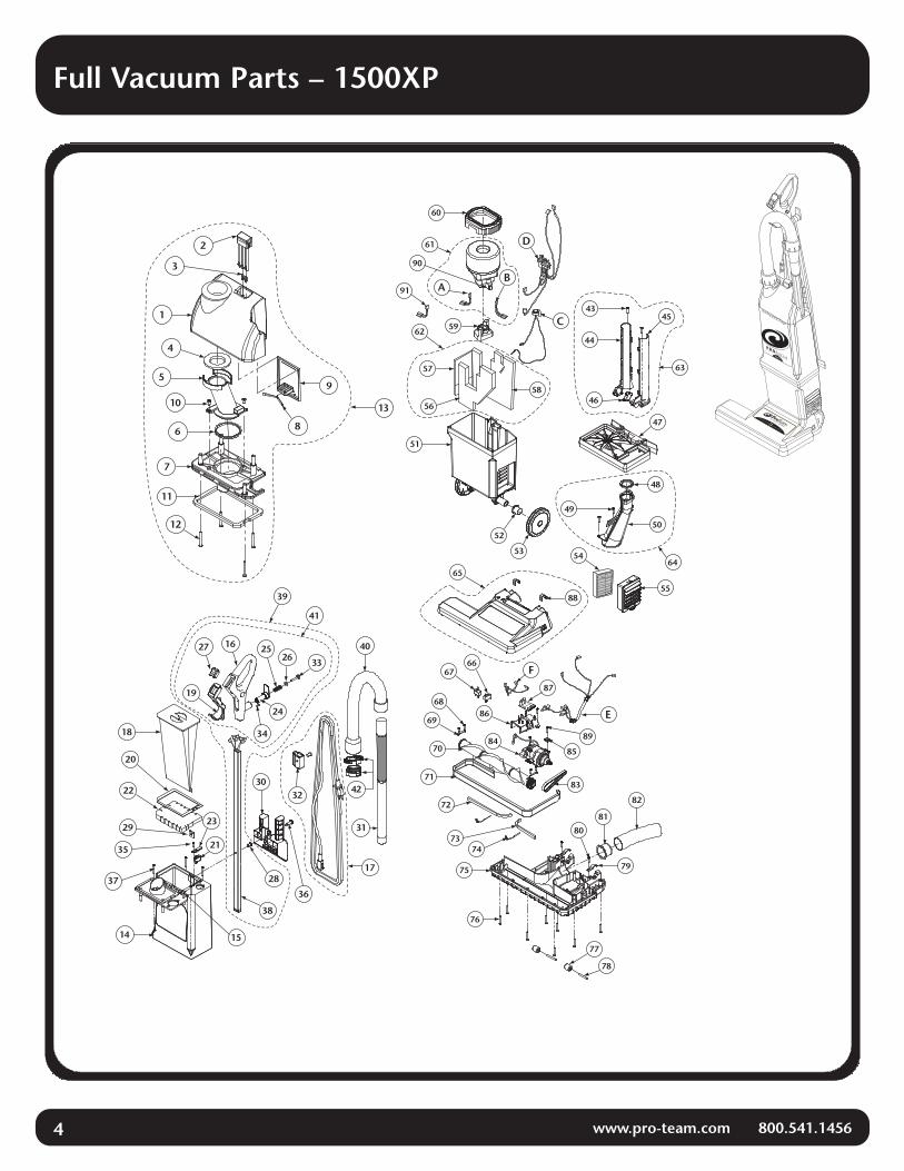
Full Vacuum Parts – 1500XP
1
2
3
4
5
6
7
8
9
10
11
12
13
14 15
16
18
19
20
21
22
23
24
2526
27
28
29
30
31
32
33
34
35
3637
38
39
40
41
17
42
60
AB
C
D
E
F
43
44
45
46
47
48
49
50
51
52
53 54
55
56
57
58
59
61
62
63
6465
6667
68
69
70
71
72
7374
75
76
77
78
79
80
81
82
83
8485
86
87
88
89
90
91

Full Vacuum Index – 1500XP
No. Part Name1 104234 Cover, Bag Housing, Grey F/XP
2 104232 Latch, Release, Bag Cover
3 104233 Spring, Release Button, F/Bag Cover Latch
4 104235 Seal, Transition Duct/Bag Cover, Upper
5 104236 Duct, Transition, Bag Cover, F/XP
6 104238 Seal, Transition Duct/Bag Cover Nozzle Plate, Lower
7 104239 Plate, Bag Cover Nozzle, F/XP
8 104242 Spring, Bag Cover Latch
9 104243 Plate, Bag Cover Latch
10 104505 Screw, Phillips, 4.2mm x 9.5mm
11 104241 Gasket, Bag Cover
12 104493 Screw, Phillips, 4.2mm x 35mm
13 105486 Filter Cover Kit w/Riveted Hinge and 6 Rivets
(includes: #1–12)
14 104490 Bag Housing Assembly, Grey w/Riveted Hinge & Decal
Includes Bag Cover Nozzle Plate
15 104491 Rivet F/Bag Housing Assembly
16 104255 Handle w/Over Mold and Decal
17 104284 Cord, Power, w/Strain Relief, 50' Yellow
18 103483 Intercept Micro Filter
19 105088 Handle Bezel w/Screws
20 104738 Seal, Gasket, Bag Housing
21 104283 Switch, Filter, Lock-Out
22 104281 Filter, Double Layer Motor Intake
23 104282 Cover, Switch, Filter Lock-out
24 104268 Bracket, Cord Wrap
25 104269 Spring, Compression, Cord Wrap Bracket
26 104270 Washer, Compression Spring, Cord Wrap Bracket
27 105147 Switch, Rocker, On/Off
28 104264 Bushing, Handle Tube
29 104259 Plate, Handle Nut
30 104265 Handle, Carry w/Tool Caddy, F/XP
31 104294 Wand, F/XP
32 105091 Clasp, Strain Relief, Yellow W/Ratchet Fastener
33 104271 Screw, Cord Wrap, 4mm x 38mm, Phillips Round Head
34 104509 Screw, Phillips, M4 x 10mm x .07 Pitch,
F/Handle Assembly
35 105075 Screw, Phillips, 2.9mm x 13mm, F/Switch Cover
36 104266 Screw, Handle Assembly
37 104493 Screw, Phillips, 4.2mm x 35mm
38 104958 Handle, Tube w/Wire Harness, Rivet Nut and Plug Rivet
39 104959 Handle, Tube Assembly Complete, F/XP
(includes: #16, 19, 24, 25, 26, 27, 28, 33, 34, 38)
40 104961 Hose, Assembly w/Cuffs, F/XP (includes: #42)
41 105502 Handle Kit (includes: #16, 19, 24, 25, 26, 27, 33, 34)
42 105573 Quick Release Hose Cuff
105572 Quick Detach Clip
No. Part Name43 104209 Screw, Phillips, 4.2mm x 12mm, F/Wand Guide44 104261 Guide, Wand, Upper Left45 104260 Guide, Wand, Upper Right46 104263 Switch, Wand Lockout47 104245 Bulkhead, Dark Grey48 104253 Seal, Lower Air Duct, Nitrile49 104267 Screw, Phillips, 4.2mm x 19mm, F/Lower Air Duct50 104250 Air Duct Assembly51 104536 Motor Housing, Charcoal52 104504 Bearing, Pivot53 104306 Wheel, Rear54 105136 Filter, Exhaust, HEPA Media55 104246 Cover, Filter Cartridge, Charcoal56 103532 Foam, Sound, Motor Housing, Front Panel57 103533 Foam, Sound, Motor Housing, Left Panel58 103531 Foam, Sound, Motor Housing, Rear Panel59 104247 Motor Mount, Lower Nitrile60 104249 Motor Mount, Upper Nitrile61 104957 Motor Assembly w/Jumpers (includes: A, B)62 105488 Motor Housing Sound Filter (includes: #56, 57, 58)63 105490 Wand Kit (includes: #43, 44, 45, 46)64 105489 Air Duct Kit (includes: #48, 49, 50)65 104494 Power Nozzle Cover w/Detent Springs & Decal66 104279 Switch, Safety, Power Nozzle Lockout67 104212 Circuit Breaker68 104496 Screw, Phillips, 2.9mm x 13mm, F/Brush Retainer69 104499 Retainer, Brush Roll70 104216 Brush Roll, Power Nozzle, 14"71 104218 Bumper, Power Nozzle, Vinyl72 104736 Seal, Base Cover, Air Duct, Left, 7.5" Long73 104737 Seal, Base Cover, Air Duct, Right, 5.5" Long74 104500 Brace, Formed Wire, F/Power Nozzle Base75 104221 Baseplate, Power Nozzle76 104497 Screw, Phillips, 4.2mm x 32mm, F/Base Cover77 104501 Roller, Front78 104502 Shaft, Front Roller Axle79 104503 Clamp, Rear Wheel80 104495 Screw, Phillips, 4.2mm x 19mm, F/Powerhead81 104227 Sleeve, Hose, Air Duct82 104230 Hose, Power Nozzle to Air Duct, Lower83 104217 Belt, Drive, F/Brush Roll84 104506 Motor, Power Nozzle with Crimps85 104498 Grommet, Vibration, Power Nozzle Motor, Nitrile86 104224 Cover, Air Duct, Power Nozzle87 104226 Board, Vacuum Operation Indicator88 104507 Spring, Detent, Upright Lock89 105371 Screw, Phillips, 4.2mm x 19mm,
F/Power Nozzle Motor 90 105281 Carbon Brush Set for ProForce Motor91 105760 Thermal Protector
105754 Wire Harness Kit includes:A. Harness, Jumper, RedB. Harness, Jumper, WhiteC. Sensor, Bag Full IndicatorD. Harness, Main Power SupplyE. Harness, Wire, Power NozzleF. Harness, Power Nozzle Switch
www.pro-team.com 800.541.1456 5

6 www.pro-team.com 800.541.1456
Bag Cover
104232 Bag Cover Release Latch
104233 Release Button Springs
104234 Bag Housing Cover
104235 Transition Duct/Bag Cover Upper Seal
104238 Lower Transition Duct Seal Bag Cover Nozzle Plate
104493 Phillips Screws
104241 Bag Cover Gasket
104239 Bag Cover Nozzle Plate
104236 Transition Duct Bag Cover
104505 Phillips Screws
(BOTTOM VIEW)
104243 Bag CoverLatch Plate
104242 Bag CoverLatch Spring
Fully AssembledBag Cover

Bag Cover
www.pro-team.com 800.541.1456 7
DISASSEMBLY
Tilt bag cover forward to open. Remove (4)phillips screws to release from bag covernozzle plate.
1. To release transition duct remove (2) phillipsscrews from bag cover nozzle plate.2.
Using a flathead screwdriver pry upwardon bag cover latch spring to release.4.
Insert flathead screwdriver beneath bagcover latch plate to release. Make surerounded points clear holes in bag cover.
5. Using thumb to hold in place, insert flat-head screwdriver into bag cover (neartop) to release bag cover release latch.
6.
Lift transition duct bag cover and remove.3.
To Reassemble. Repeat steps in reverse.
8 www.pro-team.com 800.541.1456
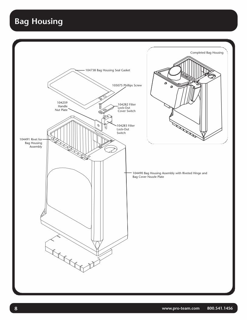
Bag Housing
Completed Bag Housing
104738 Bag Housing Seal Gasket
104282 FilterLock-OutCover Switch
105075 Phillips Screw
104283 FilterLock-OutSwitch
104490 Bag Housing Assembly with Riveted Hinge andBag Cover Nozzle Plate
104259Handle
Nut Plate
104491 Rivet forBag Housing
Assembly
Bag Housing
www.pro-team.com 800.541.1456 9
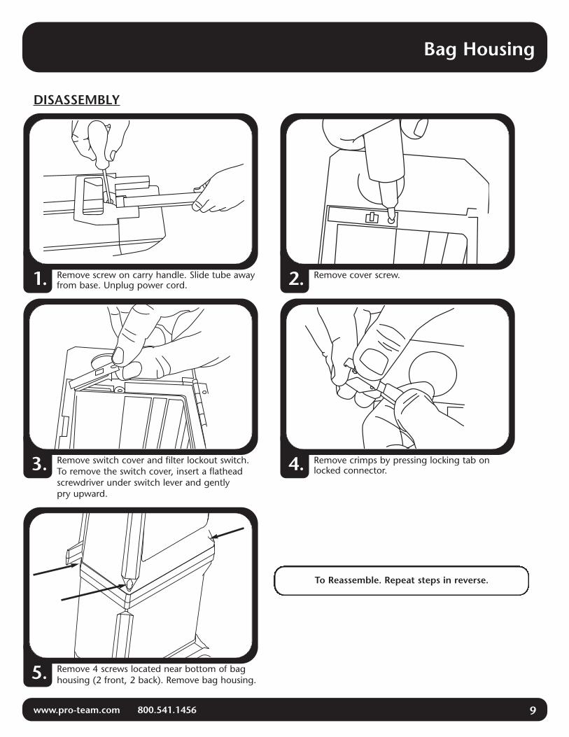
DISASSEMBLY
Remove screw on carry handle. Slide tube awayfrom base. Unplug power cord.1.
Remove switch cover and filter lockout switch.To remove the switch cover, insert a flatheadscrewdriver under switch lever and gentlypry upward.
3.
Remove 4 screws located near bottom of baghousing (2 front, 2 back). Remove bag housing.5.
Remove crimps by pressing locking tab onlocked connector.4.
Remove cover screw.2.
To Reassemble. Repeat steps in reverse.

10 www.pro-team.com 800.541.1456
Bag Housing
BAG LOCKOUT SWITCH REPLACEMENT
Open filter bag housing.Remove filter bag.1.
Remove switch cover and filter lockoutswitch. To remove the switch cover, inserta flathead screwdriver under switch leverand gently pry upward.
3. Remove crimps by pressing locking tabon locked connectors. Reverse steps toreassemble.
4.
Remove cover screw.2.

Bag Housing
www.pro-team.com 800.541.1456 11
HOSE CAP COLLAR REPAIR – For ProForce 1500XP Only
To inspect the collar, attach the quickrelease cuff to the bag cover collar. Lift thevacuum by the hose cuff. The collarshould support the weight of the vacuum.If not, the collar will fail and separate fromthe bag cover. The collar will need to beremoved from the quick release cuff andre-glued into the bag cover. If this collartest fails, proceed to Step 2.
1. Clean cuff and housing with rubbingalcohol. Apply a continuous bead of“Super Glue” type adhesive aroundthe entire perimeter of the detachedcollar. Care should be taken to avoiddrips and runs.
2.
Quickly insert collar into bag cover evenly,pressing firmly for 20 seconds to assure anadequate bond.
3.
IMPORTANT: you have only a few secondsto apply the bead of glue and seat the collarinto the bag cover.

12 www.pro-team.com 800.541.1456
Bag Housing to Motor Housing
ASSEMBLY(a) Feed bag switch wires through bag housing using
wire guide (see page 18).
(b) Align duct with opening in bag housing (APPLIES TOPROFORCE 1500XP ONLY).
(c) Bag housing assembly should fit neatlyonto bulkhead.
(d) Insert bag housing screws and tighten.
(e) Attach harness connectors to switch and placeswitch into position.
(f) Fasten switch cover with screw.
(g) If replacing the bag housing seal, do not let theseal cover the lockout switch cover opening.
NOTE: Make sure the handle nut plate (#104259) isin place before you replace the bag housinggasket seal.
104234 BagHousing Cover
105075 Switch CoverPhillips Screw
104738Bag Housing
Gasket Seal
104282 FilterLock-OutSwitch Cover
104283 FilterLock-Out Switch
(a)
(b)
104490Bag Housing
Assembly
104261 Left/104260 RightWand Guide or
105490 (both) Duct AssemblyAPPLIES TO
PROFORCE 1500XP ONLY
104536Motor Housing
104259 Handle Nut Plate
(e)
(f)
(c)
(d)(d)
(g)
(d)
(d)
Motor Housing
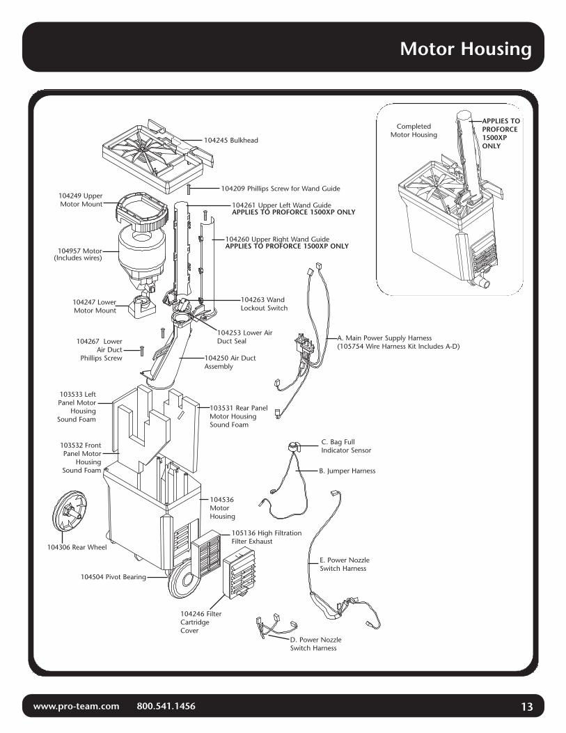
www.pro-team.com 800.541.1456 13
104245 Bulkhead
CompletedMotor Housing
104209 Phillips Screw for Wand Guide
104536MotorHousing
104246 FilterCartridgeCover
D. Power NozzleSwitch Harness
C. Bag FullIndicator Sensor
E. Power NozzleSwitch Harness
B. Jumper Harness
A. Main Power Supply Harness(105754 Wire Harness Kit Includes A-D)
105136 High FiltrationFilter Exhaust
104253 Lower AirDuct Seal
104250 Air DuctAssembly
104267 LowerAir Duct
Phillips Screw
104260 Upper Right Wand GuideAPPLIES TO PROFORCE 1500XP ONLY
104261 Upper Left Wand GuideAPPLIES TO PROFORCE 1500XP ONLY
104263 WandLockout Switch
104249 UpperMotor Mount
104957 Motor(Includes wires)
104247 LowerMotor Mount
103533 LeftPanel Motor
HousingSound Foam
103532 FrontPanel Motor
HousingSound Foam
103531 Rear PanelMotor HousingSound Foam
104306 Rear Wheel
104504 Pivot Bearing
APPLIES TOPROFORCE1500XPONLY

14 www.pro-team.com 800.541.1456
Motor Housing
DISASSEMBLY
(Continued on page 15)
Remove handle and power cord. Open bag housingcover. Remove Intercept Micro™ Filter.1.
Remove switch cover and filter lockout switch.To remove the switch cover, insert a flathead screw-driver under switch lever and gently pry upward.
3.
Remove switch cover screw.2.
Remove crimps by pressing locking tab onconnector.4.

Motor Housing
www.pro-team.com 800.541.1456 15
DISASSEMBLY (CONTINUED FROM PG 14)
(Continued on page 16)
Remove (4) bag housing screws and bag housing.5.
Remove upper motor mount. Lift motor fromhousing.7.
Remove the bag full indicator tube (tube notpictured) from the bulkhead and lift off thebulkhead.
6.
Disconnect motor crimps from motor and fromlower air duct. Remove motor.8.
16 www.pro-team.com 800.541.1456
Motor Housing
DISASSEMBLY (CONTINUED FROM PG 15)
(Continued on page 17)
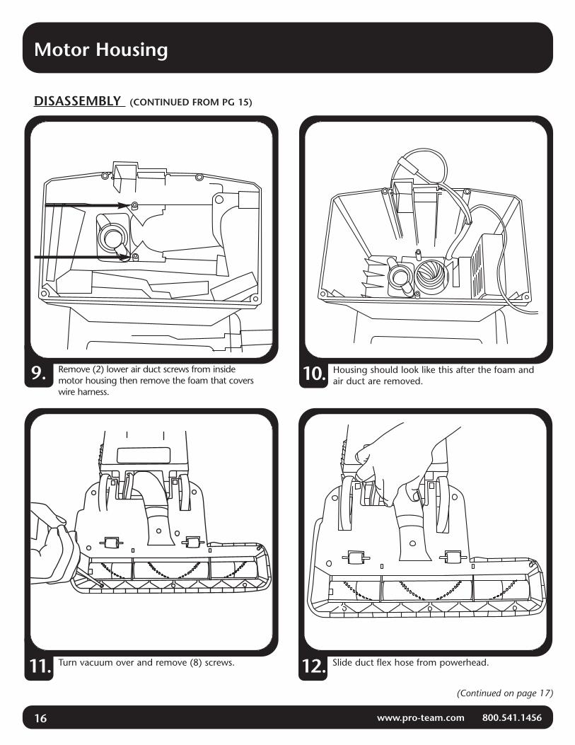
Remove (2) lower air duct screws from insidemotor housing then remove the foam that coverswire harness.
9.
Turn vacuum over and remove (8) screws.11.
Housing should look like this after the foam andair duct are removed.10.
Slide duct flex hose from powerhead.12.

Motor Housing
www.pro-team.com 800.541.1456 17
DISASSEMBLY (CONTINUED FROM PG 16)
To Reassemble. Repeat steps in reverse.
Remove (2) wheel clamp screws on left andright wheels.13. Remove wheels and pivot bearings.
Pull wire harness through body housing.14.
Remove exhaust filter.15.

18 www.pro-team.com 800.541.1456
Motor Housing
WAND GUIDE – For ProForce 1500XP Only
Separate left wand guide from right wand guide byinserting two fingers between two guides. Use a flat tipscrewdriver with opposite hand to unsnap lock latchesand pry open wand guides using your two fingers.
1.
Switch Installation. Seat switch into the left wandguide. Snap lock latches together all the way upboth sides of the wand guides.
2.
Unsnap latches closestto fingers first
Left Wand Guide
Lock Latches
Right Wand Guide
Guide Latch
Switch
Latch Hole
Note: Use care in prying open latches withscrewdriver so as not to break tabs.
Wire Harness
www.pro-team.com 800.541.1456 19
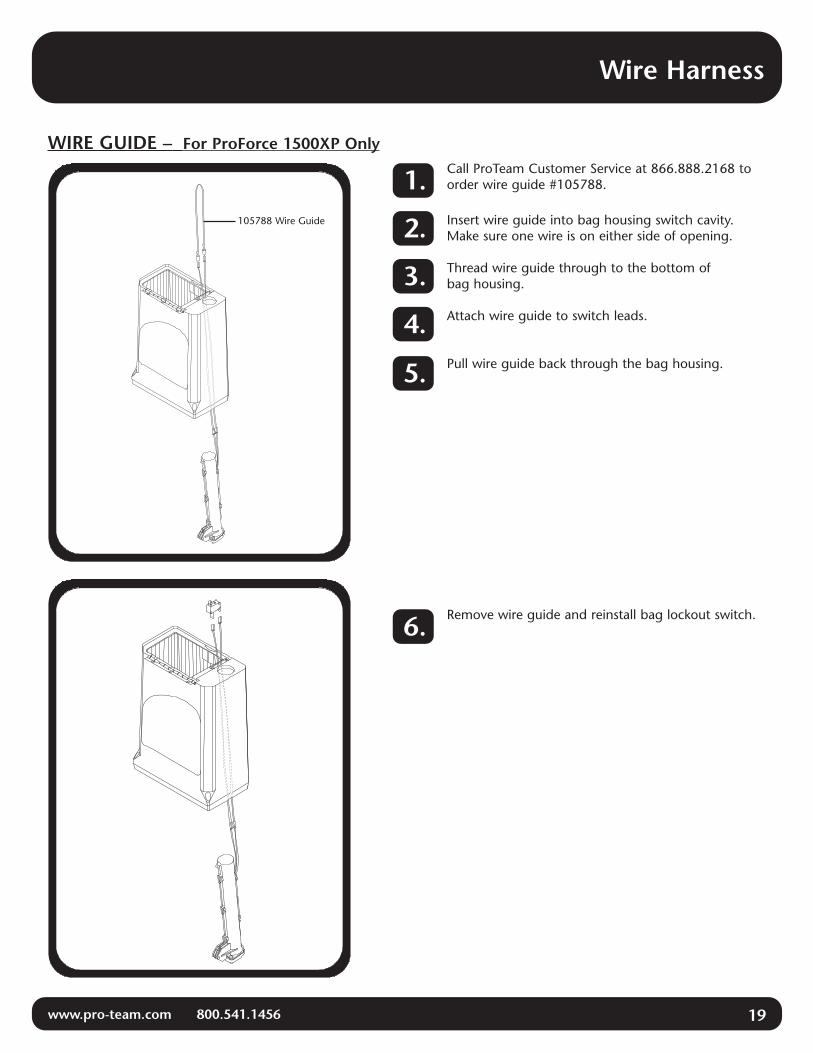
WIRE GUIDE – For ProForce 1500XP Only
Insert wire guide into bag housing switch cavity.Make sure one wire is on either side of opening.
Call ProTeam Customer Service at 866.888.2168 toorder wire guide #105788.
Thread wire guide through to the bottom ofbag housing.
Attach wire guide to switch leads.
Pull wire guide back through the bag housing.
Remove wire guide and reinstall bag lockout switch.
1.
2.
3.
4.
5.
6.
105788 Wire Guide
20 www.pro-team.com 800.541.1456
Wire Harness
WIRE HARNESS REPLACEMENT
(Continued on page 21)
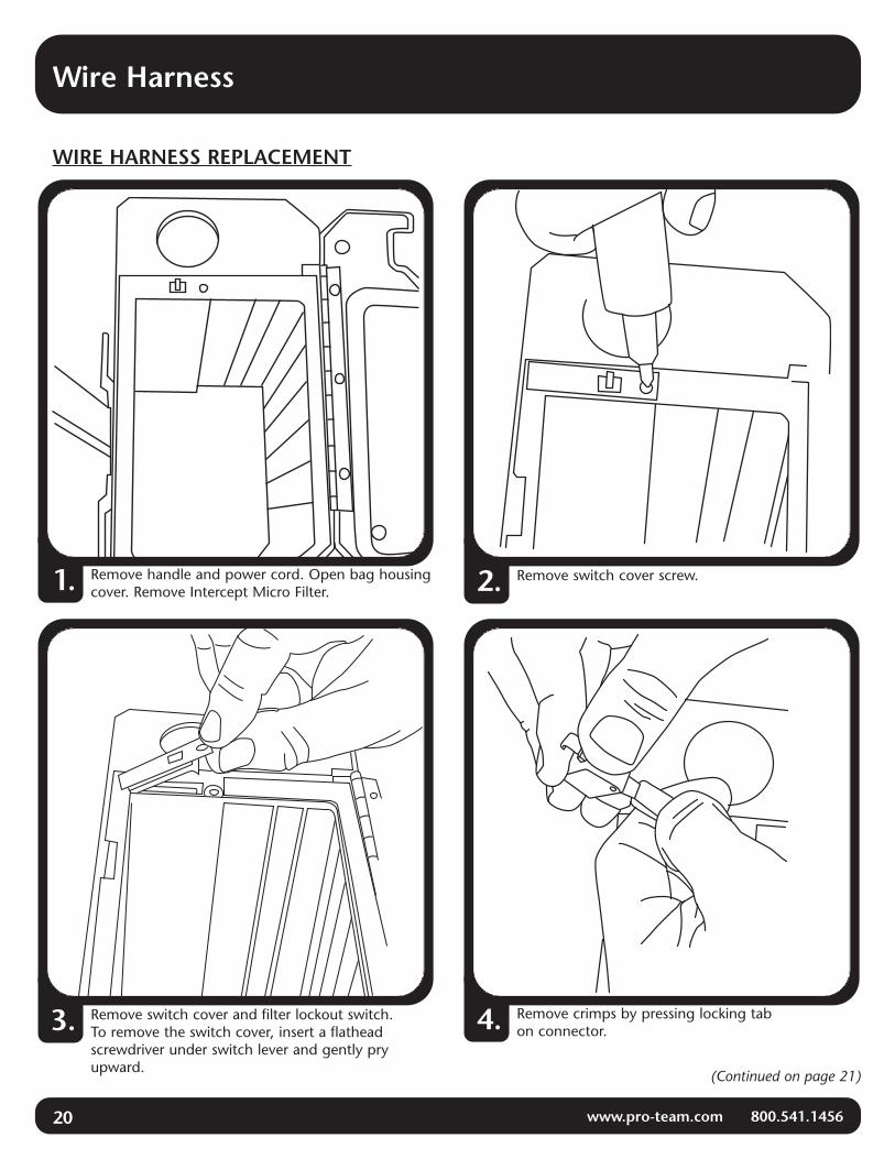
Remove handle and power cord. Open bag housingcover. Remove Intercept Micro Filter.1.
Remove switch cover and filter lockout switch.To remove the switch cover, insert a flatheadscrewdriver under switch lever and gently pryupward.
3.
Remove switch cover screw.2.
Remove crimps by pressing locking tabon connector.4.

Wire Harness
www.pro-team.com 800.541.1456 21
WIRE HARNESS REPLACEMENT (CONTINUED FROM PG. 20)
(Continued on page 22)
Remove (4) bag housing screws and removebag housing.5.
Remove upper motor mount.7.
Remove the bag full indicator tube (tube not pic-tured) from the bulkhead and lift off the bulkhead.6.
Disconnect motor crimps from motor andremove motor.8.

22 www.pro-team.com 800.541.1456
Wire Harness
WIRE HARNESS REPLACEMENT (CONTINUED FROM PG. 21)
(Continued on page 23)
Remove (2) lower air duct screws from insidemotor housing then remove the foam that coverswire harness.
9. Cut lower wire harness between the motor housingand the base assembly. Pull the air duct system,air duct hose and lower wire harness out of themotor housing.
10.
Note: Rotate brass fitting so it cannot be trappedby the lower duct.
Insert new power nozzle wire harness inmotor housing, locking brass fitting intoposition as shown.
11.
Wire Harness
www.pro-team.com 800.541.1456 23
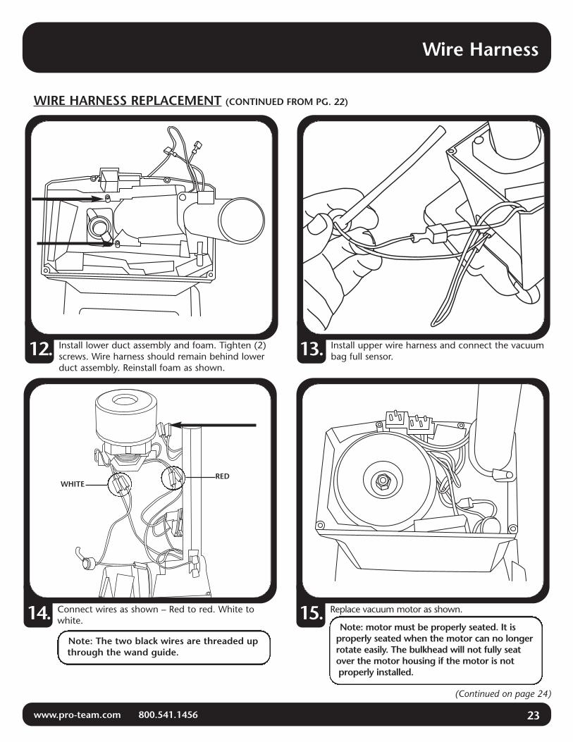
WIRE HARNESS REPLACEMENT (CONTINUED FROM PG. 22)
(Continued on page 24)
Install upper wire harness and connect the vacuumbag full sensor.13.Install lower duct assembly and foam. Tighten (2)
screws. Wire harness should remain behind lowerduct assembly. Reinstall foam as shown.
12.
Connect wires as shown – Red to red. White towhite.14.
Note: The two black wires are threaded upthrough the wand guide.
Replace vacuum motor as shown.15.Note: motor must be properly seated. It is
properly seated when the motor can no longerrotate easily. The bulkhead will not fully seatover the motor housing if the motor is notproperly installed.
WHITERED
24 www.pro-team.com 800.541.1456
Wire Harness
WIRE HARNESS REPLACEMENT (CONTINUED FROM PG. 23)
(Continued on page 25)
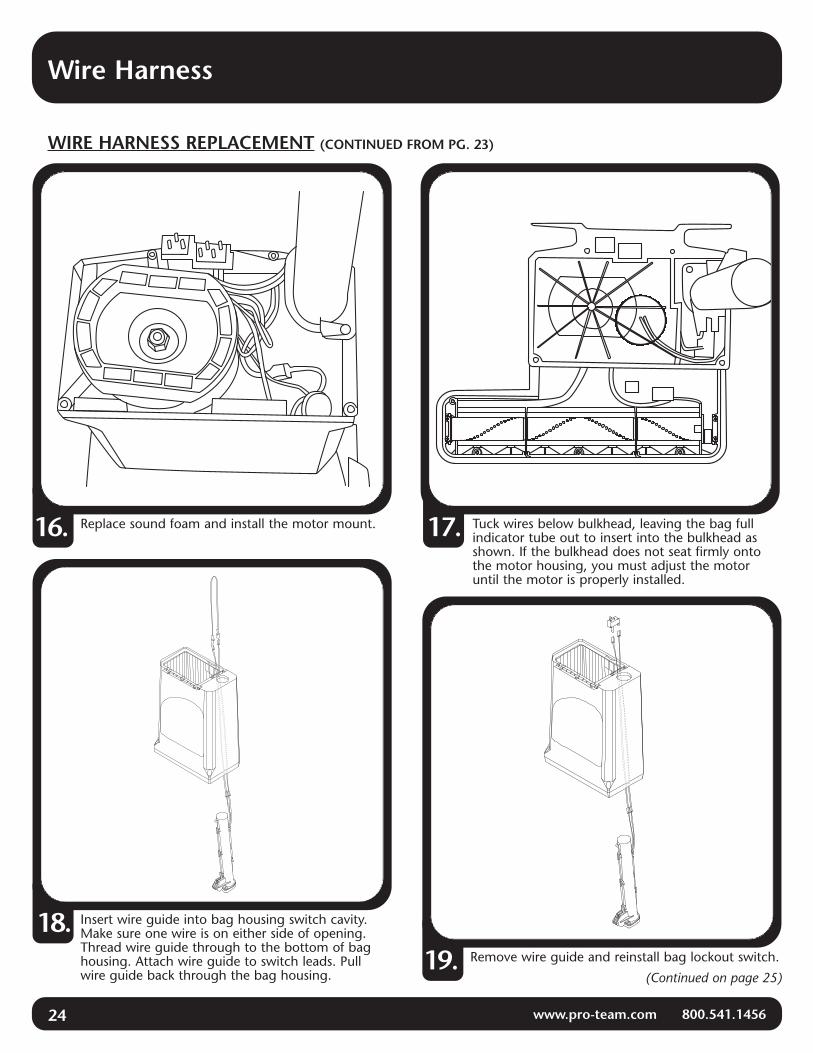
Replace sound foam and install the motor mount.16.
Insert wire guide into bag housing switch cavity.Make sure one wire is on either side of opening.Thread wire guide through to the bottom of baghousing. Attach wire guide to switch leads. Pullwire guide back through the bag housing.
18.Remove wire guide and reinstall bag lockout switch.19.
17. Tuck wires below bulkhead, leaving the bag fullindicator tube out to insert into the bulkhead asshown. If the bulkhead does not seat firmly ontothe motor housing, you must adjust the motoruntil the motor is properly installed.

Wire Harness
www.pro-team.com 800.541.1456 25
WIRE HARNESS REPLACEMENT (CONTINUED FROM PG. 24)
Remove wire ties. Remove the circuit breaker andpower nozzle lockout switch. Do not remove powernozzle motor.
23.Disconnect all wire connections.22.
To replace lower wire harness remove (8)baseplate screws and turn vacuum back over toremove base cover.
21.Attach bag housing. Insert (4) bag housing screws.Upper wire harness replacement now complete.20.
(Continued on page 26)

26 www.pro-team.com 800.541.1456
Wire Harness
WIRE HARNESS REPLACEMENT (CONTINUED FROM PG. 25)
Put the hose sleeve into the other end of the hoseand position in the base assembly. Replace thecover, air duct, and screw.
26.
Thread the air duct hose into the motor housing.25.Remove screw that holds the cover and air duct.24.
Connect wires as shown and verify orientation ofswitches.27.
BLACK
WHITERED
BLUE
(Continued on page 27)
Wire Harness
www.pro-team.com 800.541.1456 27
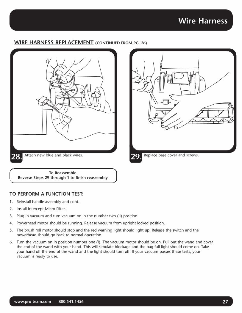
Attach new blue and black wires.
TO PERFORM A FUNCTION TEST:
1. Reinstall handle assembly and cord.
2. Install Intercept Micro Filter.
3. Plug in vacuum and turn vacuum on in the number two (II) position.
4. Powerhead motor should be running. Release vacuum from upright locked position.
5. The brush roll motor should stop and the red warning light should light up. Release the switch and thepowerhead should go back to normal operation.
6. Turn the vacuum on in position number one (I). The vacuum motor should be on. Pull out the wand and coverthe end of the wand with your hand. This will simulate blockage and the bag full light should come on. Takeyour hand off the end of the wand and the light should turn off. If your vacuum passes these tests, yourvacuum is ready to use.
28. Replace base cover and screws.29.
To Reassemble.Reverse Steps 29 through 1 to finish reassembly.
WIRE HARNESS REPLACEMENT (CONTINUED FROM PG. 26)
28 www.pro-team.com 800.541.1456
Motor
REMOVING CARBON BRUSHES
INSTALLING CARBON BRUSHES
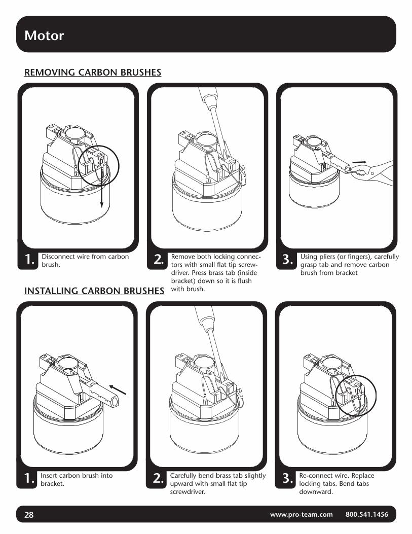
Remove both locking connec-tors with small flat tip screw-driver. Press brass tab (insidebracket) down so it is flushwith brush.
2.Disconnect wire from carbonbrush.1. Using pliers (or fingers), carefully
grasp tab and remove carbonbrush from bracket
3.
Carefully bend brass tab slightlyupward with small flat tipscrewdriver.
2. Re-connect wire. Replacelocking tabs. Bend tabsdownward.
3.Insert carbon brush intobracket.1.

Power Nozzle
www.pro-team.com 800.541.1456 29
Fully Assembled Power Nozzle
104507 Upright LockDetent Spring
104494PowerNozzleCover
104226 Vacuum Operation Indicator Board
104279 Safety Lockout Switch
104212 Circuit Breaker
104224 Air Duct Cover104496 BrushRetainer Phillips Screw
104499 BrushRoll Retainer
104506 Motor104216 14" Brush Roll
104736/104737 Air DuctBase Cover Seal
104230 Lower Hose to Air Duct
104503 Rear Wheel Clamp
104495 Phillips Screw104227 Air Duct Hose Sleeve
104217 Brush Roll Drive Belt
104502 Front RollerAxle Shaft
104498 Motor Vibration Grommet
105371 Motor Phillips Screw
104500 Formed Wire Brace
104218 Vinyl Bumper
104497 Base Cover Phillips Screw
104501Front Roller
104221 Baseplate
30 www.pro-team.com 800.541.1456
Power Nozzle
ASSEMBLY
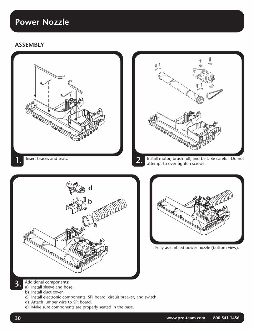
Insert braces and seals.1. Install motor, brush roll, and belt. Be careful. Do notattempt to over-tighten screws.2.
Fully assembled power nozzle (bottom view).
Additional components:a) Install sleeve and hose.b) Install duct cover.c) Install electronic components, SPI board, circuit breaker, and switch.d) Attach jumper wire to SPI board.e) Make sure components are properly seated in the base.
3.
a
b
d
Power Nozzle to Body Assembly
www.pro-team.com 800.541.1456 31
ASSEMBLY
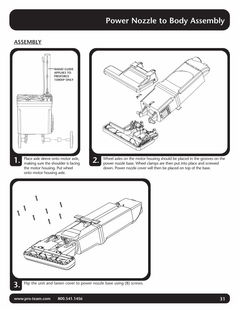
Wheel axles on the motor housing should be placed in the grooves on thepower nozzle base. Wheel clamps are then put into place and screweddown. Power nozzle cover will then be placed on top of the base.
2.Place axle sleeve onto motor axle,making sure the shoulder is facingthe motor housing. Put wheelonto motor housing axle.
1.
Flip the unit and fasten cover to power nozzle base using (8) screws.3.
WAND GUIDEAPPLIIES TOPROFORCE1500XP ONLY

32 www.pro-team.com 800.541.1456
Power Nozzle
HOSE SLEEVE REPLACEMENT
Remove (8) screws from base plate. Turn vacuumover and pull base cover off powerhead.1. Unclip circuit board and move aside.2.
Pull off air duct cover. Pull out hose sleeve.Replace with new sleeve. Sleeve must sit in groove tobe properly seated. Reverse steps to reassemble.
4.Unscrew air duct cover.3.

Power Nozzle
www.pro-team.com 800.541.1456 33
PIVOT BEARING REPLACEMENT/WHEEL REPLACEMENT
To Reassemble.Repeat steps in reverse.
Remove 8 screws from base plate.1. Turn vacuum over and pull base coveroff powerhead.2.
Remove right and left rear wheel clamps.3. Lift bag housing from powerhead and removewheel.4.
Remove old pivot bearing. Install new pivotbearing.5.

34 www.pro-team.com 800.541.1456
Hose and Power Cord
104961 Hose Assembly with Cuffs
105091 Strain Relief Clasp
104294Wand
104265 CarryHandle withTool Caddy
104266 HandleAssembly Screw
104284 Power Cord with Strain Relief
105572QuickReleaseHose Clip
105573QuickReleaseHose Cuff
WAND AND HOSE APPLY TOPROFORCE 1500XP ONLY

Handle
www.pro-team.com 800.541.1456 35
105147 On/Off Rocker Switch
104958 Handle Tube with Wire Harness, Rivet Nut and Plug Rivet
104255 Handle with Over Mold and Decal
104268 Cord Wrap Bracket
105088 Handle Bezel with Screws
104271 Cord Wrap Phillips Screw
104270 Cord Wrap Bracket Compression Spring Washer
104269 Cord Wrap Bracket Compression Spring
104509 Handle Assembly Phillips Screw
104264 Handle Tube Bushingand Screw

36 www.pro-team.com 800.541.1456
Handle
HANDLE ASSEMBLY
Use a flathead screwdriver (fig. 1) to pry bottom of switch from the handle body. Disconnect all wires from switchposts by depressing locking tab on base of crimps. (Fig. 2)1.
Feed handle wire harness through new handle andreplace screw at the base of the handle (fig. 4).3.Remove screw at base of handle and remove from
handle tube (fig. 3).2.
fig. 1 fig. 2
fig. 3 fig. 4
(Continued on page 37)

Handle
www.pro-team.com 800.541.1456 37
HANDLE ASSEMBLY (CONTINUED FROM PG. 36)
Feed wires through opening on handle bezel.4. Using the diagram provided above, attach wiresto switch. Orient the switch box with the IIposition on the down side.
a) Attach the first plug on the brown wire to themiddle left spade.
b) Attach the first plug on the blue wire to thelowest left spade. Wait to attach the lastblue plug.
c) Wrap the second brown plug underneath blueand attach to the middle right spade.
d) Attach the last blue plug to the upperright spade. The bottom right spade willremain unattached.
e) Connect the red wire to the top right spade.
5.
I0II
position II must be on the bottombefore attaching wires to spades
longblue
longbrown
shortbrown
shortblue red
back of switchfront of switch
BLUE BLU
E
BLUE
RED
RED
RED
RED RED
BR
OW
N B
RO
WN
BROWN
BROWN
When finished with steps a through e your finalwire connection configuration should appearas above.
6. Install the switch into the handle bezel. Place the longBLUE, BROWN, then RED wires between the screw bossesin that order (as shown). BROWN and BLUE wire loopsmust be positioned above the screw bosses on the handlebezel as shown.
(Continued on page 38)

38 www.pro-team.com 800.541.1456
Handle
HANDLE ASSEMBLY (CONTINUED FROM PG. 37)
Lay the long red, brown and blue wires betweenthe circular shoulders and gently place handlebezel into handle.
9. Slide tab A into handle slot B and press firmly intoplace at C. Be sure all switch wires are routedbetween screw bosses to ensure that the wires donot get damaged. Insert screws into bezel (fig. 9).
10.
fig. 8
AB
C
Press the switch into place in the handle bezel.The II position should be closest to the front ofthe bezel.
8.Switch must remain flat to the handle bezel wheninstalled into handle body as shown.7.

Handle and Power Cord
www.pro-team.com 800.541.1456 39
NEW CORD AND STRAIN RELIEF REPLACEMENT
(Continued on page 40)
Use a flathead screwdriver and hammer to push thestrain relief towards the handle. Snap off remainingstrain relief.
1. Remove screw from carry handle and remove carryhandle.2.
Feed new strain relief clasp over the new powercord. Slide strain relief up to the groove on thepower cord and snap strain relief clasp into place.
NOTE: Use care when sliding the strain relief claspover the handle tube bushing so as not to damagebushing.
4.Slide handle tube away from base. Unplug oldpower cord.3.
40 www.pro-team.com 800.541.1456
Handle and Power Cord
NEW CORD AND STRAIN RELIEF REPLACEMENT (CONTINUED FROM PAGE 39)
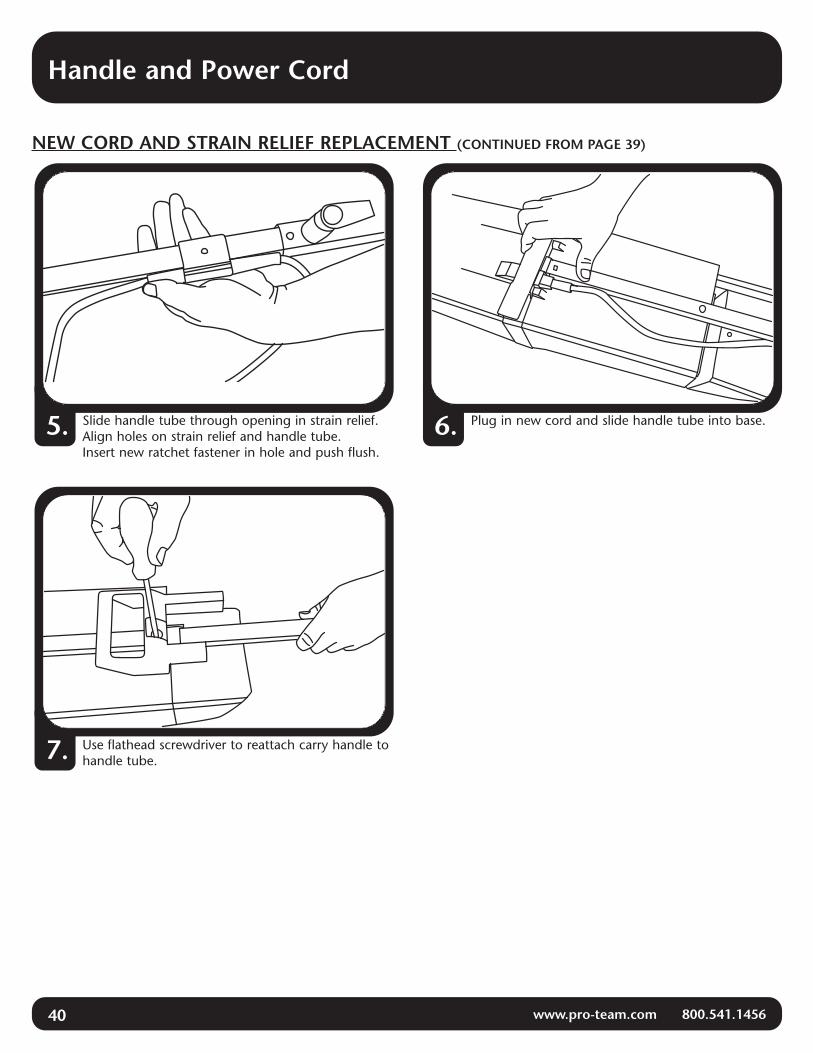
Slide handle tube through opening in strain relief.Align holes on strain relief and handle tube.Insert new ratchet fastener in hole and push flush.
5. Plug in new cord and slide handle tube into base.6.
Use flathead screwdriver to reattach carry handle tohandle tube.7.

Final Vacuum Assembly
www.pro-team.com 800.541.1456 41
ASSEMBLYInstall all 3 filters:(a) Intercept Micro Filter(b) Motor Intake Filter(c) Exhaust Filter
Install Power Cord and Handle withOver Mold and Decal.Attach with Handle Tube Bushing andCarry Handle with Tool Caddy.
Wrap Power Cord aroundCord Wrap Post.
Hose Assembly with Cuffs
Wand
Carry Handlewith
Tool Caddy
Cord Wrap Post
(a)
(b)
(c)
HandleTubeBushing Handle
AssemblyScrew
Cord WrapScrew
Power Cord
QuickReleaseHoseCuff
Handle with OverMold and Decal
1.
2.
3.
WAND AND HOSE APPLY TOPROFORCE 1500XP ONLY
42 www.pro-team.com 800.541.1456
Troubleshooting–Clearing Hose and Wand Obstructions
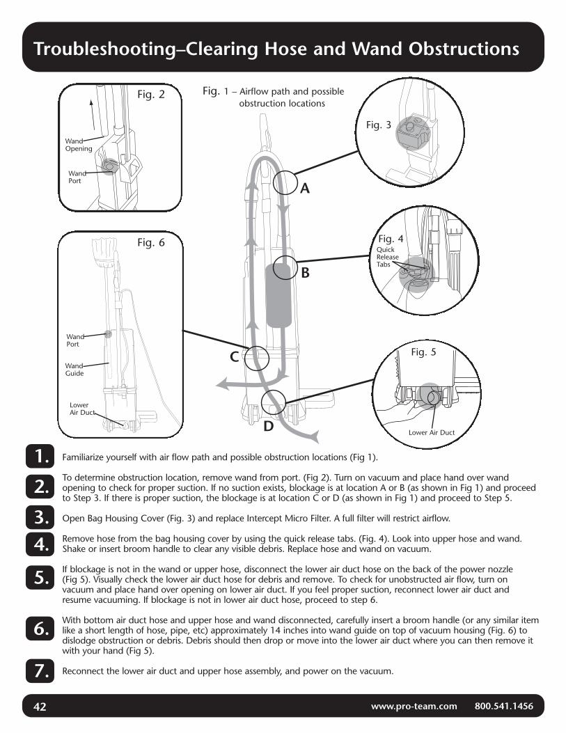
Familiarize yourself with air flow path and possible obstruction locations (Fig 1).
To determine obstruction location, remove wand from port. (Fig 2). Turn on vacuum and place hand over wandopening to check for proper suction. If no suction exists, blockage is at location A or B (as shown in Fig 1) and proceedto Step 3. If there is proper suction, the blockage is at location C or D (as shown in Fig 1) and proceed to Step 5.
Open Bag Housing Cover (Fig. 3) and replace Intercept Micro Filter. A full filter will restrict airflow.
Remove hose from the bag housing cover by using the quick release tabs. (Fig. 4). Look into upper hose and wand.Shake or insert broom handle to clear any visible debris. Replace hose and wand on vacuum.
If blockage is not in the wand or upper hose, disconnect the lower air duct hose on the back of the power nozzle(Fig 5). Visually check the lower air duct hose for debris and remove. To check for unobstructed air flow, turn onvacuum and place hand over opening on lower air duct. If you feel proper suction, reconnect lower air duct andresume vacuuming. If blockage is not in lower air duct hose, proceed to step 6.
With bottom air duct hose and upper hose and wand disconnected, carefully insert a broom handle (or any similar itemlike a short length of hose, pipe, etc) approximately 14 inches into wand guide on top of vacuum housing (Fig. 6) todislodge obstruction or debris. Debris should then drop or move into the lower air duct where you can then remove itwith your hand (Fig 5).
Reconnect the lower air duct and upper hose assembly, and power on the vacuum.
WandPort
Fig. 6
Lower Air Duct
A
B
C
D
Fig. 2
WandPort
Fig. 1 – Airflow path and possible obstruction locations
Fig. 3
Fig. 4QuickReleaseTabs
Lower Air Duct
Fig. 5WandGuide
WandOpening
1.
2.
3.4.
5.
6.
7.

Electrical
www.pro-team.com 800.541.1456
HA
ND
LE
SOC
KET
AC
L1
L2
AC
BLU
E W
IRE
RED
WIR
E
BLAC
K W
IRE
GRE
EN W
IRE
BU
LKH
EAD
CO
NN
ECTO
R
Pow
er H
arn
ess
1057
75
F5/6
M
M
F5
/6
FILT
ER B
AG
SW
ITC
H
N/O
Co
nta
cts
1042
83
1 N
ewto
n (
Bro
wn
/Wh
ite)
<BLACK> <B
LAC
K>
<GR
EEN
>
<RED
>
<BLU
E>
<BLU
E>
M
F5
POW
ER N
OZ
ZLE
SW
ITC
H
N/C
Co
nta
cts
1042
79
4 N
ewto
n (
Bro
wn
)
POW
ER N
OZ
ZLE
JAM
C
IRC
UIT
BR
EAK
ER
Man
ual R
eset
10
4212
WA
ND
SW
ITC
H
(XP
On
ly)
N/O
Co
nta
cts
1042
63
4 N
ewto
n (
Bro
wn
)
PRES
SUR
E SE
NSO
R
N/O
Co
nta
cts
1048
27
MA
IN P
OW
ER
RO
CK
ER S
WIT
CH
10
5147
(A
ssy.
105
087)
POW
ER N
OZ
ZLE
HA
RN
ESS
1054
46
MA
IN V
AC
UU
M B
AG
FULL
IND
ICA
TOR
RED
BR
USH
RO
LL JA
M IN
DIC
ATO
R
RED
N
OR
MA
L O
PER
ATI
ON
IND
ICA
TOR
G
REE
N
BLU
E JU
MPE
R 1
0482
6
<BLA
CK
>
<WH
ITE>
<RED
>
RED
JUM
PER
10
4856
VA
CU
UM
MO
TOR
10
4170
WH
ITE
JUM
PER
10
4955
<BLA
CK
>
<BR
OW
N>
BR
USH
RO
LL M
OTO
R
1045
06
<RED> <RED> <WH
ITE>
IND
ICA
TOR
PC
B
1042
26
C1
C4
C3
C2
M
M
M
M
M
M
M
M
M
F3/4
M
7 F3
/4
M7
F12
F5/6
M10
F8/4
<BLACK>
M
M
F1/2
F1/2
M
M
F 1
F8/9
<BLACK>
F13/
9
39K
, 1/2
W
F11
F8
F8/9
F8/4
M
7
39K
, 1/2
W
F3/4
M
7
F13/
9
39K,
1/2
W
<BLACK> F12
F3/4
M
7
CO
NN
ECTO
RD
ESC
RIP
TIO
NTA
BSE
RIE
SW
IRE
1Fe
mal
e A
MP
0.03
2.2
50 F
lag
18-1
22
Slee
ve A
MP
.250
Fla
g18
-22
3Fe
mal
e A
MP
0.03
20.
187
20-1
64
Slee
ve A
MP
0.18
722
-18
5Fe
mal
e A
MP
0.03
20.
250
22-1
86
Slee
ve A
MP
0.25
22-1
87
Mal
e A
MP
0.03
20.
187
22-1
88
Fem
ale
AM
P0.
020
0.18
720
-14
9Sl
eeve
AM
P0.
187
2-#1
810
Mal
e A
MP
0.03
20.
250
22-1
811
Fem
ale
AM
P0.
020
.187
PB
20-1
612
Fem
ale
AM
P0.
032
0.18
72-
#18
13Fe
mal
e A
MP
0.02
00.
187
2-#1
8
43

5118 N. Sawyer Ave., Boise, Idaho 83714 • 800.541.1456www.pro-team.com
#106243 Revised 3/07