Embed Size (px)
Citation preview

Installation and Operation
Profile
PLS 200 Library
Printed in USA or United Kingdom
Tektronix, Inc.PO Box 1000Wilsonville, OR 97070-1000 USA
1-800-547-8949 (USA and Canada)1-503-682-7300
http://www.tek.com

ii PLS200 Library Installation and Operation
Copyright Copyright 1996 Tektronix, Inc. Wilsonville, Oregon.
Printed in the United States of America or the United Kingdom. All rightsreserved. This document may not be copied in whole or in part, or otherwisereproduced except as specifically permitted under U.S. copyright law, withoutthe prior written consent of Tektronix, Inc., P.O. Box 1000, Wilsonville, Oregon97070-1000.
Some portions are reprinted with permission:
Copyright 1994 – 1996 Exabyte Corporation. All rights reserved.
Disclaimer Tektronix, Inc., makes no representation or warranties with respect to thecontents of this document and specifically disclaims any implied warranties ofmerchantability or fitness for any particular purpose. Further, Tektronix, Inc.reserves the right to revise this publication without obligation of Tektronix, Inc.to notify any person or organization of such revision or changes.
Trademark Notices TEKTRONIX and TEK are registered trademarks of Tektronix, Inc. Profile isa trademark of Tektronix, Inc.
EXABYTE, EXAPAK, EXB, FileSECURE, LANCourier, and NetSECUREare registered trademarks of Exabyte Corporation. Eagle, EXA, EXAFacts,EXAsoft, EXATAPE, and SCIMON are trademarks of Exabyte Corporation.
Other trade names used in this document are trademarks or registeredtrademarks of the manufacturers or vendors of the associated products.
Revision StatusRev Date Description
December 1996 Original Issue; Manual Part Number 070-9619-00

PLS200 Library Installation and Operation iii
Contents
WelcomeAbout this Manual...................................................................................... xviRelated Documentation............................................................................. xvi
Conventions Used in this Manual ......................................................... xviTektronix Product Support........................................................................ xvii
United States and Canada .................................................................. xviiEurope ................................................................................................. xviiAsia and South America ...................................................................... xviiWorld Wide .......................................................................................... xvii
About the PLS200....................................................................................xviiiLibrary Elements ....................................................................................... xxi
Chapter 1 Installing the HardwarePreparing for Installation ..............................................................................1
Unpack the Library ..................................................................................1Check the Accessories ............................................................................2Protect the Library Against ESD..............................................................2Prepare the Library..................................................................................3Verify Your Profile Software Version .......................................................3
Installing the SCSI Adapter Into the VDR.....................................................3Installing the Library Hardware.....................................................................7
Install the Library Into a Rack ..................................................................8Unlatch and Open the Door...................................................................14Remove the Packing Foam ...................................................................15Move the CHM Out of the Way..............................................................16Prepare and Install Cartridges...............................................................17Install Cartridge Magazines ...................................................................20Install a Cleaning Cartridge ...................................................................22Close the Library Door...........................................................................23Connect the SCSI Cables......................................................................23Connect the Power Cord .......................................................................28Power-on the Library .............................................................................28SCSI Adapter Board Software Update ..................................................30

Contents
iv PLS200 Library Installation and Operation
Chapter 2 Configuring the LibraryMain Screen ...............................................................................................32Displaying the Configuration Menu ............................................................32Setting the SCSI IDs ..................................................................................34Setting Other Configuration Options ..........................................................36
Setting Parity Checking .........................................................................36Adjusting the Contrast ...........................................................................37Setting the Back Light............................................................................38Setting the Library Date.........................................................................38Setting the Library Time ........................................................................39Checking the Serial Number..................................................................39Checking the Tape Drive Model ............................................................41
Chapter 3 Operating the LibraryUsing the Operator Panel...........................................................................43
Main Screen ..........................................................................................43Error Codes ...........................................................................................44Main Menu.............................................................................................44Operator Keys .......................................................................................46
Operating in Different Control Modes.........................................................46SCSI Interface Mode .............................................................................47LCD Interface Mode ..............................................................................4725/9 Pin Serial Port Mode......................................................................47Changing the Control Mode...................................................................48
Replacing Data Cartridge Magazines.........................................................49Resetting the Library ..................................................................................51
Reset Key ..............................................................................................52Power-on Reset.....................................................................................52
Chapter 4 Operating the Tape DrivesMonitoring the Tape Drive LEDs ................................................................53Displaying Information About Tape Drives .................................................54
Fields on Drive Status Screen ...............................................................55Additional Fields on Mammoth Drive Status Screen .............................56
Ejecting a Cartridge Manually ....................................................................57
Chapter 5 Maintaining the LibraryReplacing Tape Drives or Drive Blanks......................................................59
Using Drive Blanks ................................................................................59Replacing Tape Drives ..........................................................................60
Replacing the Fuse ....................................................................................63Replacing the Air Filter ...............................................................................65Cleaning the Front Window........................................................................67

Contents
PLS200 Library Installation and Operation v
Chapter 6 Packing and Shipping the LibraryReturning the Library for Service ............................................................... 69Shipping the Library................................................................................... 69
Preparing the Library for Shipping ........................................................ 70Inserting the Packing Foam in the Library ............................................ 71Removing the Library From the Rack ................................................... 73Packing the Library in the Shipping Containers .................................... 77
Chapter 7 Performing DiagnosticsUsing the LCD Diagnostics Menu.............................................................. 83
Summary of Diagnostic Tests ............................................................... 84Accessing the Diagnostics Menu .......................................................... 85Specifying Element Indexes.................................................................. 85Stopping Diagnostic Tests .................................................................... 85Self Test................................................................................................ 86Position to Element ............................................................................... 86Park....................................................................................................... 87Move Cartridge ..................................................................................... 87Scan...................................................................................................... 88Scan with Range................................................................................... 89Home Gripper ....................................................................................... 89Home CHM ........................................................................................... 90Cycle Pick/Place ................................................................................... 90Cycle Gripper ........................................................................................ 91Cycle S Axis.......................................................................................... 92Cycle L Axis .......................................................................................... 92Cycle Drum ........................................................................................... 93Cycle Solenoid ...................................................................................... 93Cycle E/E .............................................................................................. 94
Configuring the Serial Ports for Diagnostics .............................................. 95
Chapter 8 Using the Library Info MenuAccessing the Library Info Menu ............................................................... 97Using the SCSI Menu ................................................................................ 98
SCSI Mode Parameters ........................................................................ 98SCSI Reservations.............................................................................. 100SCSI Sense Data................................................................................ 102
Viewing Statistics..................................................................................... 104Viewing System Sensors ......................................................................... 106Viewing Command History ...................................................................... 108Using the Inventory Menu........................................................................ 110
Bar Code Label Information ................................................................ 110Element Occupied Information............................................................ 112Element Position Information .............................................................. 113

Contents
vi PLS200 Library Installation and Operation
Chapter 9 TroubleshootingProblems With Installation........................................................................115Problems With Tape Drive Operation.......................................................116Problems With Library Operation .............................................................117If You Cannot Resolve the Problem.........................................................117
Appendix A SpecificationsStorage Capacity......................................................................................119Operating Environment ............................................................................119Power .......................................................................................................120Power Cord Requirements .......................................................................120SCSI Terminator Specifications ...............................................................120SCSI Cable Specifications .......................................................................121
Appendix B LCD Error Codes
Appendix C Bar Code Label SpecificationMaterials for the Label..............................................................................131Dimensions of the Label...........................................................................132Bar Code Characters................................................................................133
Checksum Character...........................................................................134Bar Code Element Widths ...................................................................135
Quality ......................................................................................................136Spots and Voids ..................................................................................136Edge Quality ........................................................................................136Reflectance and Contrast ....................................................................136Label Degradation after Exposure to Light ..........................................137
Optional Features.....................................................................................137Alphanumeric Characters ....................................................................137Background Color................................................................................138
Testing the Bar Code Labels....................................................................138
Index

Contents
PLS200 Library Installation and Operation vii
FiguresElement indexes for PLS200................................................................... xxiii
1-1 Removing the top covers ............................................................................. 41-2 Removing the circuit board hold-downs....................................................... 51-3 Screw locations for board mounting bracket................................................ 61-4 Attaching the slide rails................................................................................ 91-5 Adjusting the distance between the front mounting brackets .................... 101-6 Installing the library in a rack ..................................................................... 111-7 Attaching the screws to the sides of the library ......................................... 121-8 Securing the library in the rack .................................................................. 131-9 Opening the door ....................................................................................... 141-10 Removing the packing foam from the library ............................................. 151-11 Moving the CHM to the bottom of the long axis......................................... 161-12 Positioning a bar code label on a data cartridge........................................ 171-13 Setting the write-protect switch on a data cartridge................................... 181-14 Installing data cartridges in the magazine ................................................. 191-15 Installing a cartridge magazine in the library ............................................. 211-16 Installing a cartridge in the fixed cartridge slot........................................... 221-17 Installing the terminators and SCSI jumpers ............................................. 241-18 SCSI connections from the VDR to the PLS200 ....................................... 251-19 SCSI connections through the PDX103 to the PLS200 ............................ 261-20 SCSI connections through the PRS200 to the PLS200 ............................ 272-1 Operator panel........................................................................................... 313-1 Library menu structure............................................................................... 453-2 Opening the library door ............................................................................ 493-3 Replacing a cartridge magazine ................................................................ 504-1 Eject button................................................................................................ 575-1 Removing and installing a tape drive......................................................... 615-2 Replacing the fuse ..................................................................................... 635-3 Replacing the air filters .............................................................................. 655-4 Replacing the air filter inside the air filter grille .......................................... 66

Contents
viii PLS200 Library Installation and Operation
6-1 Installing the packing foam in the library ....................................................716-2 Adjusting the packing foam ........................................................................726-3 Removing the screws from the front of the rack.........................................746-4 Removing the screws from the sides of the library.....................................756-5 Lifting the library from the rack ...................................................................766-6 Placing the antistatic bag over the library...................................................776-7 Placing the cushioned packaging around the library..................................786-8 Placing the accessory box and top on the library.......................................796-9 Placing the carton over the library..............................................................806-10 Securing the banding material....................................................................81C-1 Dimensions of the bar code label .............................................................132C-2 Area for printing bar code characters .......................................................133C-3 Element dimensions; spots and voids ......................................................135C-4 Area for printing alphanumeric characters ...............................................137

PLS200 Library Installation and Operation ix
General Safety Summary
WARNING: The instructions in this manual are for use byqualified service personnel only. To avoid personal injury,do not perform any servicing unless you are qualified to doso. Refer to all safety summaries before performing service.
Review the following safety precautions to avoid injury andprevent damage to this product or any products connected to it.
While using this product, you may need to access other parts ofthe system. Read theGeneral Safety summaryin other systemmanuals for warnings and cautions related to operating thesystem.
Injury Precautions
Use Proper PowerCord
To avoid fire hazard, use only the power cord specified for thisproduct.
Ground the Product This product is grounded through the grounding conductor of thepower cord. To avoid electric shock, the grounding conductormust be connected to earth ground. Before making connectionsto the input or output terminals of the product, ensure that theproduct is properly grounded.
Do Not OperateWithout Covers
To avoid electric shock or fire hazard, do not operate this productwith covers or panels removed.
Use Proper Fuse To avoid fire hazard, use only the fuse type and rating specifiedfor this product.
Do Not operate inWet/Damp
Conditions
To avoid electric shock, do not operate this product in wet ordamp conditions.
Do Not Operate in anExplosive
Atmosphere
To avoid injury or fire hazard, do not operate this product in anexplosive atmosphere.
!!

General Safety Summary
x PLS200 Library Installation and Operation
Avoid ExposedCircuitry
To avoid injury, remove jewelry such as rings, watches, andother metallic objects. Do not touch exposed connections andcomponents when power is present.
Product Damage Precautions
Use Proper PowerSource
Do not operate this product from a power source that appliesmore than the voltage specified.
Provide ProperVentilation
To prevent product overheating, provide proper ventilation.
Do Not Operate WithSuspected Failures
If you suspect there is damage to this product, have it inspectedby qualified service personnel.
Safety Terms and Symbols
Terms in ThisManual
These terms may appear in this manual:
WARNING: Warning statements identify conditions or practicesthat can result in personal injury or loss of life.
CAUTION: Caution statements identify conditions or practicesthat can result in damage to the equipment or other property.
Terms on theProduct
These terms may appear on the product:
DANGER indicates a personal injury hazard immediatelyaccessible as one reads the marking.
WARNING indicates a personal injury hazard not immediatelyaccessible as you read the marking.
CAUTION indicates a hazard to property including the product.
!!
!!

Safety Terms and Symbols
PLS200 Library Installation and Operation xi
Symbols on theProduct
The following symbols may appear on the product:
DANGER high voltage
Protective ground (earth) terminal
ATTENTION – refer to manual!!

xii PLS200 Library Installation and Operation
Service Safety Summary
WARNING: These instructions are for use by qualifiedservice personnel only. To avoid personal injury, do notperform any servicing unless you are qualified to do so.Refer to all safety summaries before performing service.
Do Not ServiceAlone
Do not perform internal service or adjustment of this productunless another person capable of rendering first aid andresuscitation is present.
Disconnect Power To avoid electric shock, disconnect the main power by meansof the power cord or, if provided, the power switch.
Use Care WhenServicing With
Power On
Dangerous voltages or currents may exist in this product.Disconnect power and remove battery (if applicable) beforeremoving protective panels, soldering, or replacingcomponents.
To avoid electric shock, do not touch exposed connections
!!

xiii
Regulatory Information
EC Declaration of ConformityTektronix, Inc.Video Networking Division14180 SW Karl Braun DriveP.O. Box 500Beaverton, Oregon 97077-0001 U.S.A.
Tektronix, Inc., Video Networking Division, declares on 27 September, 1996, under our soleresponsibility, that the PLS200 Video video Archive system to which this declaration relates,is in conformity with the following standard(s) or other normative document(s):
EMC Directive 89/336/EEC
EC EN55022 Limits and methods of measurement of radio interferencecharacteristics of Information Technology Equipment
EC 50082-11992
Electromagnetic compatibility generic immunity standard Part 1:Residential, commercial, and light industry.
Low Voltage Directive 73/23/EEC
EN60950 Safety of Information Technology Equipment includingElectrical Business Equipment (includes Appendix ZB)
Environmental Phenomena Test Specification Basic Standard
Radio-FrequencyElectromagnetic Field
27-500 MHz3V/m (unmodulated)
IEC801-3
Electrostatic Discharge 8kV (charge Voltage) IEC801-2
Fast Transients commonmode on Signal lines
0.5kV (peak)5/50 Tr/Th ns5kHz Rep. Frequency
IEC801-4
AC mains ports 1.0kV (peak)5/50 Tr/Th ns5kHz Rep. Frequency

Regulatory Information
xiv
Certifications and CompliancesCanadian Certified
Power CordsCanadian approval includes the products and power cordsappropriate for use in the North America power network. Allother power cords supplied are approved for the country of use.
FCC EmissionControl
This equipment has been tested and found to comply with thelimits for a Class A digital device, pursuant to Part 15 of the FCCRules. These limits are designed to provide reasonable protectionagainst harmful interference when the equipment is operated in acommercial environment. This equipment generates, uses, andcan radiate radio frequency energy and, if not installed and usedin accordance with the instruction manual, may cause harmfulinterference to radio communications. Operation of thisequipment in a residential area is likely to cause harmfulinterference in which case the user will be required to correct theinterference at his own expense. Changes or modifications notexpressly approved by Tektronix can affect emission complianceand could void the user’s authority to operate this equipment.
Canadian EMCNotice of
Compliance
This digital apparatus does not exceed the Class A limits forradio noise emissions from digital apparatus set out in the RadioInterference Regulations of the Canadian Department ofCommunications.
Le présent appareil numérique n’emet pas de bruitsradioélectriques dépassant les limites applicables aux appareilsnumeriques de la classe A préscrites dans le Règlement sur lebrouillage radioélectrique édicte par le ministère desCommunications du Canada.
EN55022 Class AWarning
For products that comply with Class A. In a domesticenvironment this product may cause radio interference in whichcase the user may be required to take adequate measures.

PLS200 Library Installation and Operation xv
Congratulations on selecting the Tektronix PLS200 Library. Your new libraryprovides automated data storage, archiving, backup, and retrieval for TektronixProfile Video Disk Recorders (VDRs).
The library's robotic cartridge handling mechanism (CHM) responds tocommands from the VDR to move 8mm data cartridges between tape drives andstorage slots, while the tape drives read and write data. You can insert andremove cartridges through the entry/exit port without opening the library door.
The PLS200 includes 80 data cartridge slots and four tape drives. The library isconnected to the VDR by three wide, differential SCSI buses.
Reset
Enter
Escape
Help
9619-6
Profile
PLS 200
Welcome

Welcome
xvi PLS200 Library Installation and Operation
About this ManualThis manual provides the information you need to install, configure, operate,maintain, and diagnose problems with the PLS200 Library and its enclosed8mm tape drives. The operator information in this manual covers only theoperation of the library from the library’s operator panel. Information about theoperation of the library from the Profile Video Disk Recorder and its softwareis available in theProfile System User Manual.
Related DocumentationThe following documents are available from Tektronix:
• Profile System User Manual
• PLS200 Service Manual
• Profile Software Developer’s Kit
Conventions Used in this Manual
Boxed characters indicate keys on the library's keypad.
NOTE: Notes provide hints or suggestions about the topic or procedure beingdiscussed.
➤ Important Information next to the word “Important” will help youcomplete a procedure or avoid extra steps.
The “attention” symbol and the word “CAUTION” precede information youmust know to avoid damaging the library or tape drives or losing data.
The “attention” symbol and the word “WARNING!” precede informationyou must know to avoid personal injury.
Enter
!
!

Tektronix Product Support
PDR 100 1.4 Release Notes xvii
Tektronix Product SupportYou can get technical assistance, check on the status of problems, or report newproblems by contacting our Product Support Group.
United States and CanadaMonday–Friday 5:30AM–5:00PM Pacific Time — (800) 547-8949
EuropeMonday–Friday 9:00AM–5:30PM
Email: [email protected]
Asia and South America
World Wide24-hour Emergency Hotline: (503) 685-2345(Contract and warranty customers)
World Wide Web:http://www.tek.com/Profile/Support
FTP Site: ftp.tek.com (IP address: 134.62.48.21)
Email: [email protected]
Users Group: [email protected]
Austria 222-799-3535 Netherlands 010-495-4255
Belgium 02-714-3401 Norway 22-83-85-69
Denmark 3543-5259 Spain 91-564-4692
Finland 161-691-98559 Sweden 08-679-8419
Germany 069-935-25001 Switzerland 041-210-6009
Italy 44-1908-681-706 United Kingdom 01908-681-703
Luxembourg 400-848 Other 44-1908-681-703
Australia 61-2-888-7066 Korea 82-2-528-5299
Brazil 55-11-543-1911 Mexico 52-5-666-6333
Hong Kong 852-2585-6688 Singapore 65-356-3900
Japan 81-3-3448-3111 Taiwan 886-2-765-6362

Welcome
xviii PDR 100 1.4 Release Notes
About the PLS200The following illustrations and descriptions summarize the important libraryfeatures.
Operator Panel
The operator panel includes a four-line liquid crystal display (LCD) and akeypad. You use the operator panel to configure the library and monitoroperations. If necessary, you can tilt the LCD for easier viewing.
Reset
Enter
Escape
Help
9619-7
Reset
Enter
Escape
Help
Entry/exitport

About the PLS200
PDR 100 1.4 Release Notes xix
Entry/Exit Port and Transport Assembly
The entry/exit port allows you to insert or remove individual cartridges from thelibrary without opening the door. The entry/exit transport assembly moves thetransport arm to and from the entry/exit port to pick up cartridges.
Drum assembly
The drum assembly holds the data cartridge magazines and rotates 180 degreesin either direction to position the magazines in front of the cartridge handlingmechanism (CHM).

Welcome
xx PDR 100 1.4 Release Notes
Data cartridge magazines
Data cartridge magazines are the removable carriers for the 8mm datacartridges. The magazines snap onto mounting plates on the library's rotatingdrum assembly and allow easy removal and replacement of cartridges. Eachmagazine has individual cartridge slots for 10 cartridges. The PLS200 containsup to eight cartridge magazines.
Fixed cartridge slot
The fixed cartridge slot, located directly above the tape drives, provides astorage location for a single cartridge. This slot is normally used to store an8mm cleaning cartridge.
Tape drives
The PLS200 uses four Exabyte Mammoth 8mm half-height tape drives with awide, differential SCSI configuration.
Drive carrier
When you purchase the library, each tape drive in the library is fitted inside adrive carrier. The drive carrier allows you to slide the drive in and out of thelibrary if the tape drive needs repair.
CAUTION: To avoid possible damage to the tape drive, do not remove it fromthe drive carrier.!

Library Elements
PDR 100 1.4 Release Notes xxi
Drive blank (not shown)
Drive blanks are “empty” drive carriers with solid faceplates. If you plan tooperate the library with fewer than four tape drives, you must install driveblanks in the empty drive positions. The drive blanks ensure correct air flowthrough the library for cooling, compliance with EMI regulations, and in someconfigurations, correct SCSI connection.
Cartridge handling mechanism (CHM)
The cartridge handling mechanism (CHM) moves cartridges between cartridgeslots, tape drives, and the entry/exit port.
Bar code scanner
The high-speed bar code scanner, mounted on the CHM, reads bar code labelsaffixed to the cartridges to track individual cartridges. Cartridge labelinformation becomes part of the library's cartridge inventory stored innonvolatile RAM.
Serial ports (not shown)
Two serial ports (25-pin and 9-pin) at the back of the library allow an externalcomputer to communicate with the tape drives and the library across a serialcable. By running a special diagnostic program, service personnel can performdiagnostics, upgrade firmware, and test CHM motion.
SCSI connectors (not shown)
The library has ten SCSI connectors, accessible through the cabling bay on theback.
Library ElementsThe library contains four types of elements:
• The CHM is themedium transport element.
• The entry/exit port is theimport/export element.
• The cartridge slots are thestorage elements.
• The tape drives are thedata transfer elements.

Welcome
xxii PDR 100 1.4 Release Notes
Each element has an element index, which is the number you must specifywhen you use the entry/exit port. Element indexes must be the same as thedefault element addresses used in SCSI commands.
The following figure shows the element indexes for the PLS200.
Element indexes for PLS200

PLS200 Library Installation and Operation 1
Chapter 1Installing the Hardware
This chapter describes how to install and set up the library hardware.
Preparing for InstallationBefore installing the library, complete the preliminary steps listed in the tablebelow. Each step is described on the following pages.
Unpack the LibraryComplete the unpacking steps printed on the box. Save the packing materials incase you need to ship the library later.
✔ Step Description
1 Unpack the library.
2 Check the accessories.
3 Protect the library against ESD.
4 Obtain a fork lift or at least four people.
5 Verify your Profile software version.

Chapter 1 Installing the Hardware
2 PLS200 Library Installation and Operation
Check the AccessoriesMake certain you received the following accessories packed with the PLS200:
• Slide rails and mounting hardware
• Four power cords (North America, United Kingdom, Europe, Australia)
• BusLogic BT-757CD SCSI bus adapter board
• Three SCSI cables
• One SCSI terminator
• Four SCSI jumpers
• Eight Data Cartridge Magazines with covers
• Eighty data cartridges
• Two cleaning cartridges
• One spare drive blank (in addition to those installed)
• Bar code labels for the data cartridges (three sheets)
• PLS200 Operation and Installation Manual
• PLS200 Order Information Technical Data Sheet
Protect the Library Against ESDIf you remove the cover from the library, its internal components aresusceptible to damage from electrostatic discharge (ESD). To ensure that thework area is as free from ESD as possible, place a grounded, static protectionmat on the work surface, and wear a static protection wrist band. If a mat andwristband are unavailable, discharge static electricity from your body beforetouching the inside of the library or the tape drives. (Touch a known groundedsurface, such as your computer's metal chassis.)

Prepare the Library
PLS200 Library Installation and Operation 3
Prepare the LibraryThe slide rails and mounting hardware for rack-mounting the library areshipped in the box with the library. The library weighs 152 pounds (69 kg) withfour tape drives installed. Before installing the library, make sure that your rackhas extension support legs and that you have at least four people or two peopleand a small fork lift.
Verify Your Profile Software VersionThe PLS200 requires Profile Software version 2.0 or higher, and WindowsNT3.51 or higher.
Installing the SCSI Adapter Into the VDRBefore you install the PLS200 hardware, install the SCSI adapter board into theProfile video disk recorder. The SCSI adapter board provides an EISA-to-SCSIinterface that allows the Media Manager or similar software on the VDR tocontrol the library’s cartridge handling mechanism. The procedures that followtake you step-by-step through the recommended sequence for installation of theSCSI adapter board.
WARNING: The VDR is too heavy for one person to remove from anequipment rack. To avoid possible injury, get help when removing the VDRfrom its rack.
WARNING: Before performing any installation or maintenance procedures,be sure that:
• the rear-panel power switch is in the off position
• the power cord is disconnected from the video disk recorder and the outlet
!!
!

Chapter 1 Installing the Hardware
4 PLS200 Library Installation and Operation
1. Loosen the front panel retaining screws and pull the cabinet out until all threeslide sections latch.
2. Remove the top covers in the order shown in Figure 1-1. The front covermust be removed first since it overlaps the rear cover. Use a T-10 TORXdriver to remove the screws.
NOTE: Take care not to lose these cabinet screws. They are required to meet the EMIspecifications for the VDR.
Figure 1-1 Removing the top covers
2
1

Installing the SCSI Adapter Into the VDR
PLS200 Library Installation and Operation 5
3. Remove the two circuit board hold-downs as shown in Figure 1-2. Bothhold-downs are held in place by T-10 TORX head screws, and must beremoved in order to install the SCSI adapter board.
➤ Important Be sure to remove the jumper as described in the following step.If the jumper is left in place, the VDR will display an error when initializingthe SCSI adapter board.
4. Unpack the SCSI adapter board and remove the jumper from W1 on theboard. Refer to the manual packed with the board to locate the jumper.
Figure 1-2 Removing the circuit board hold-downs

Chapter 1 Installing the Hardware
6 PLS200 Library Installation and Operation
5. Remove the blank cover plate from the J4 slot in the VDR rear panel.
6. Plug the SCSI adapter board into the J4 socket and press down till the boardis fully plugged into the socket.
7. Install the mounting screw in the top of the bracket inside the cabinet (asshown in Figure 1-3).
8. Re-install the hold-downs. Align each hold-down over the circuit boards andreplace the mounting screws.
9. Re-install the cabinet covers. Do not tighten any of the screws until all thescrews are started.
10. Install the VDR power cord, butdo not turn on the VDR.
Figure 1-3 Screw locations for board mounting bracket
1
2

Installing the Library Hardware
PLS200 Library Installation and Operation 7
Installing the Library HardwareUse the following table as a checklist for installing the library.
WARNING: Before performing any installation or maintenance procedures,be sure that the library power switch is in the off position and that the powercord is disconnected from the library and the outlet.
✔ Step Description
1 Install the library into a rack
2 Unlatch and open the door
3 Remove the packing foam
4 Move the CHM
5 Prepare and install cartridges in magazines
6 Install the magazines in the library
7 Install a cleaning cartridge
8 Close the library door
9 Connect the SCSI cables
10 Connect the power cord
11 Power on the library
12 Complete the SCSI adapter board software update
!
Chapter 1 Installing the Hardware
8 PLS200 Library Installation and Operation
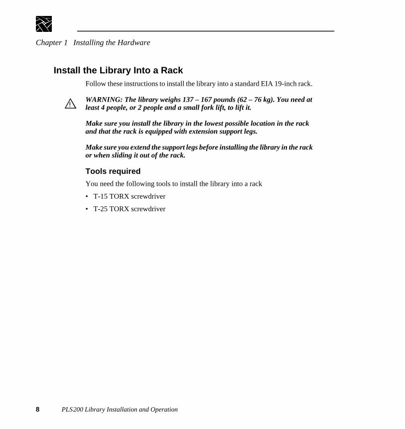
Install the Library Into a RackFollow these instructions to install the library into a standard EIA 19-inch rack.
WARNING: The library weighs 137 – 167 pounds (62 – 76 kg). You need atleast 4 people, or 2 people and a small fork lift, to lift it.
Make sure you install the library in the lowest possible location in the rackand that the rack is equipped with extension support legs.
Make sure you extend the support legs before installing the library in the rackor when sliding it out of the rack.
Tools required
You need the following tools to install the library into a rack
• T-15 TORX screwdriver
• T-25 TORX screwdriver
!

Install the Library Into a Rack
PLS200 Library Installation and Operation 9
Installing the Slide Rails
1. Identify the holes on the rack where you want to install the library. Thelibrary will extend 1 to 2 inches (3 to 4 cm) below the slide rails.
2. If the rack does not have threaded holes, attach the eight clip nuts over theholes (see Figure 1-4).
3. Using a T-25 TORX driver and eight 10-32× 0.5 screws, attach, but do nottighten, the slide rails to the rack (see Figure 1-4).
Figure 1-4 Attaching the slide rails

Chapter 1 Installing the Hardware
10 PLS200 Library Installation and Operation
4. As shown in Figure 1-5, adjust the distance between the front mountingbrackets to 17 inches (44.8 cm).
Figure 1-5 Adjusting the distance between the front mounting brackets
5. Tighten the screws.
6. Repeat steps 4 and 5 for the rear mounting brackets.
58---

Install the Library Into a Rack
PLS200 Library Installation and Operation 11
Installing the Library
1. Extend the extension support legs on the rack.
2. Slide the inside rails as far out of the rack as they will go (see Figure 1-6).
Figure 1-6 Installing the library in a rack
3. Remove the air filter grilles from the front of the library by lifting the outsideedges and pulling the grilles away from the library (see Figure 1-6).
4. Using four people, or two people and a fork lift, lift the library by the handlesand lower it onto the slide rails so the mounting tabs on each side of thelibrary fit into the slots in the rails (see Figure 1-6). Make sure all sixmounting tabs are fitted securely into the slots.

Chapter 1 Installing the Hardware
12 PLS200 Library Installation and Operation
5. Press the spring clips and slide the library most of the way into the rack.
6. Install one 8-32× button head screw into the screw hole on each rail, as
shown in Figure 1-7.
Figure 1-7 Attaching the screws to the sides of the library
716------

Install the Library Into a Rack
PLS200 Library Installation and Operation 13
7. If the holes in the rack are not threaded, install a clip nut on each side of therack, as shown in Figure 1-8.
Figure 1-8 Securing the library in the rack
8. Slide the library completely into the rack. Use a T-25 TORX driver to insertthe two 10-32× 1.0 pan head screws on the front panel, as shown inFigure 1-8. These screws prevent the library from sliding out of the rack.
9. Replace the air filter grilles on each side of the front panel.

Chapter 1 Installing the Hardware
14 PLS200 Library Installation and Operation
Unlatch and Open the DoorTo open the door, turn the door latch handle one quarter turn to the right, asshown in Figure 1-9. Pull open the door.
Figure 1-9 Opening the door
Reset
Enter
Escape
Help
9619-8
Reset
Enter
Escape

Remove the Packing Foam
PLS200 Library Installation and Operation 15
Remove the Packing FoamRemove the packing foam from the library as shown in Figure 1-10.
1. Take out the center cross piece shown at arrow 1.
2. Move the vertical piece to the right as shown by arrow 2 to disengage it fromthe CHM.
3. Bend the top of the vertical piece to the left and remove the top cross piece.
4. Pull the top of the vertical piece out of the door enough to allow removal ofthe bottom cross piece, then take out the vertical piece.
Figure 1-10 Removing the packing foam from the library
➊➋
➌
➍

Chapter 1 Installing the Hardware
16 PLS200 Library Installation and Operation
Move the CHM Out of the WayMove the cartridge handling mechanism (CHM) so it is not blocking themagazine mounting plates on the drum. To move the CHM, reach in throughthe door and push against thebase of the CHM, sliding it firmly to the bottomof the long axis until it stops. See Figure 1-11.
➤ Important Do not touch the lens on the bar code scanner; smudges on thelens can cause scanning errors.
Figure 1-11 Moving the CHM to the bottom of the long axis

Prepare and Install Cartridges
PLS200 Library Installation and Operation 17
Prepare and Install CartridgesBefore installing data cartridges in the library, attach the bar code labels and setthe write-protect switches.
➤ Important Two types of EXATAPE™ 8mm Data Cartridges are available:advanced metal evaporated (AME) and metal particle (MP). Use only theAME tape cartridges in the PLS200. The tape drives in PLS200 cannot writeor read to the MP tape cartridges.
Attach Bar Code Labels
Position the label as shown in Figure 1-12, using the recessed area on thecartridge for guidance. Make sure you orient the label correctly. Forinformation on how to prepare bar code labels, refer toAppendix C, Bar CodeLabel Specification.
NOTE: Be sure to attach a bar code label to the cleaning cartridge as well as the datacartridges.
➤ Important If you create your own bar code labels, be sure to follow thespecification precisely.
Figure 1-12 Positioning a bar code label on a data cartridge
CAUTION: If you remove a bar code label from a data cartridge withoutreplacing it, make sure to clean the label area thoroughly. Bar code labelscan leave adhesive on the label area, which may cause the data cartridge tostick to the CHM.
!

Chapter 1 Installing the Hardware
18 PLS200 Library Installation and Operation
Set the Write-protect Switches
Make sure the write-protect switch on each data cartridge is set appropriately(see Figure 1-13). You can use a ball-point pen or similar instrument to movethe write-protect switch. If the write-protect switch window is red, the cartridgeis write-protected.
Figure 1-13 Setting the write-protect switch on a data cartridge

Prepare and Install Cartridges
PLS200 Library Installation and Operation 19
Install Data Cartridges in the Magazines
The empty magazines are packed in the box of accessories shipped with thePLS200.
1. Place the magazine on its feet with the single mounting guide toward theright, as shown in Figure 1-14.
2. Position each cartridge so that the bar code label is on top and thewrite-protect switch is toward the front (see Figure 1-14).
3. Insert the cartridge into the magazine slot.
NOTE: Very little force is needed to install a data cartridge. If it does not snap intoplace easily or if it protrudes further than the magazine’s center rib, checkthe orientation of the cartridge.
Figure 1-14 Installing data cartridges in the magazine

Chapter 1 Installing the Hardware
20 PLS200 Library Installation and Operation
Install Cartridge Magazines
➤ Important Use only magazines designed for half-height Exabyte 8mmlibraries. Do not use Exabyte Data Cartridge Holders designed forfull-height Exabyte 8mm libraries.
The following instructions describe how to install cartridge magazines onto themounting plates on the drum.
CAUTION: Make sure the CHM and its cabling are safely out of the waybefore installing cartridge magazines.
1. If necessary, manually rotate the drum to access the mounting plate whereyou want to install the magazine.
2. On the magazine mounting plate, locate the roller on the top end of the plate.
3. Position the magazine over the mounting plate with the single mountingguide toward the top, as shown in Figure 1-15.
4. Insert the bottom end of the magazine first, then snap the magazine into placeby pressing against the top.
!

Install Cartridge Magazines
PLS200 Library Installation and Operation 21
Figure 1-15 Installing a cartridge magazine in the library

Chapter 1 Installing the Hardware
22 PLS200 Library Installation and Operation
Install a Cleaning CartridgeThe following procedure describes how to manually install a cleaning cartridgein the fixed cartridge slot. To replace this cartridge later, use the ExportCartridge and Import Cartridge functions of the Media Manager in the ProfileTool Box. Refer to the discussion of the Media Manager in theProfile SystemUser Manual.
CAUTION: Use Tektronix-approved cleaning cartridges only. Using clothswabs, cotton swabs, cleaning agents, or cleaning cartridges not approved byTektronix will void the tape drive warranty.
To install a cleaning cartridge in the fixed cartridge slot:
1. Position the cartridge so that the window showing the tape reels is toward thetop (see Figure 1-14).
➤ Important The cleaning cartridge must have a bar code label.
2. Insert the cartridge into the fixed cartridge slot until it snaps into place.
Figure 1-16 Installing a cartridge in the fixed cartridge slot
!

Close the Library Door
PLS200 Library Installation and Operation 23
Close the Library DoorClose the library door and turn the door latch handle a quarter turn to the left.
Connect the SCSI CablesThe library is connected to the Profile system with three SCSI cables. One cablecontrols the library and attaches to the SCSI adapter board. The other twocables transfer data to and from the tape drives. These cables connect to theSCSI A and SCSI B busses at the VDR Disk Recorder boards, the PDX103, orPRS 200 as shown in Figures 1-18, 1-19, and 1-20. All cables are fast wide,differential with screw fasteners on both ends.
The SCSI connectors for the library and tape drives are accessible through thecabling bay at the back of the library.
1. Remove the terminator plugs from the Master and Slave Disk Recorderboards (or from the loop-through connectors on the PDX103 or PRS200).Retain these plugs for use in the next step.
2. Install the SCSI jumpers and terminators on the PLS200 as shown inFigure 1-17.
3. Connect the SCSI cables included with the PLS200. Refer to Figures 1-18,1-19, and 1-20 as appropriate for your installation.
CAUTION: To avoid damaging the tape drives, make sure the power is off inall devices connected to the SCSI bus when you connect the tape drives to theSCSI bus.
!

Chapter 1 Installing the Hardware
24 PLS200 Library Installation and Operation
Figure 1-17 Installing the terminators and SCSI jumpers
9619-4
PLS200
Terminator
SCSI Jumper
SCSI Jumper
Terminator
Terminator
Library
Drive 1
Drive 2
Drive 3
Drive 4

Connect the SCSI Cables
PLS200 Library Installation and Operation 25
Figure 1-18 SCSI connections from the VDR to the PLS200
9619-5
J15 J14 J4
Terminator
SCSI Cable
PLS200
PDR100
SCSI Jumper

Chapter 1 Installing the Hardware
26 PLS200 Library Installation and Operation
Figure 1-19 SCSI connections through the PDX103 to the PLS200
J15 J14 J4
9619-2
Terminator
SCSI Cable
PLS200
PDX103
PDR100
SCSI Jumper

Connect the SCSI Cables
PLS200 Library Installation and Operation 27
Figure 1-20 SCSI connections through the PRS200 to the PLS200
9619-3
J15 J14
Terminator
SCSI Cable
PLS200
PRS200
AdditionalPRS200
PDR100
SCSI Jumper
J4

Chapter 1 Installing the Hardware
28 PLS200 Library Installation and Operation
Connect the Power Cord
➤ Important Tektronix ships the PLS200 with four power cords, each for usein a different location. If none of the power cords are appropriate for yourlocation, you must supply a power cord with the proper plug that meets thespecifications listed in Appendix A, Specifications.
1. Make sure that the power switch on the back of the library is off (the0 ispressed).
2. Connect the female end of the power cord to the power connector on the backof the library.
3. Plug the male end of the power cord into the power source.
NOTE: The library has autoranging voltage selection, so you do not need to changethe voltage setting.
Power-on the Library1. Make certain the library's door is closed and latched.
2. Push the power switch on the back of the library to the on (I) position.
3. Turn on the PDX103 or PRS200 if one of them is attached to the SCSI bus.
4. Turn on the Profile video disk recorder.
NOTE: When you turn on the VDR, a warning will appear that slot 2 needs to beconfigured. This is normal and is addressed when you complete the SCSIadapter board software update at the end of this chapter.
5. Wait while the library performs its power-on self-test. During this time, thefollowing activities occur:
- The cooling fan begins to rotate.
- The LCD illuminates and displays the Main Screen.
- The tape drives perform their power-on self-tests.
- The library performs its power-on self-test.

Power-on the Library
PLS200 Library Installation and Operation 29
Tape Drive Power-on Self-test
During its power-on self-test, each tape drive checks its operating conditionsand sends status information to the library.
Library Power-on Self-test
During its power-on self-test, the library:
• Engages the locking solenoid in the door.
• Moves the CHM to the home positions on the short and long axes.
• Moves the drum to the home position.
• Retracts the entry/exit port transport arm.
• Verifies the CHM's full range of motion by moving it to the top of thelong axis.
• Touches each cartridge to update the cartridge inventory.
• Moves to the home position on the long axis.
If Problems Occur...
If the library does not complete its power-on self-test and nothing is displayedon the LCD, check the following:
• Is the power switch on? (Is theI pressed?)
• Is the power cord inserted correctly?
• Is the library door closed?
• Is the video disk recorder on?
If the library does not complete its power-on self-test and the LCD displays anerror code, see Appendix B,LCD Error Codes.
For more detailed troubleshooting information, see Chapter 9,Troubleshooting.

Chapter 1 Installing the Hardware
30 PLS200 Library Installation and Operation
SCSI Adapter Board Software UpdateWhen you applied power to the Profile VDR (in the step on page 28), a warningappeared that Slot 2 needed to be configured. The following procedure updatessoftware on the VDR and enables communication between the VDR and thePLS200.
1. Double click the “Load DTI CMOS” icon to rewrite a new image intoCMOS. The console window indicates that the software has found theBT-757CD (the SCSI adapter board) and has used the correct .cmo file.
2. Restart the VDR, and verify that the card in EISA slot two initializescorrectly. At this point the Buslogic BT-757CD SCSI card will be initializedbut can not be used by the PLS200 software until you install the driver forthe SCSI adapter board.
3. Install the driver for the SCSI adapter board.
a. Double click the “Windows NT Setup” icon in the Main group.
b. Pull down the “Options” menu and select “Add/Remove SCSIAdapters...”, then click the “Add...” button.
c. Select the “Buslogic Standard SCSI Host Adaptor” driver from the listand click the “Install” button. In the box that requests the location, type“c:\i386” and click the “Continue” button.
d. Restart the Profile VDR, and log in asadministrator (hold down the shiftkey when the blue screen appears — factory-loaded password istriton).
4. Verify that Windows NT on the Profile VDR found the SCSI robot device.
a. Double click the “Windows NT Diagnostics” icon in the “AdministrativeTools” group.
b. Select “Registry Editor” found under the “Tools” menu.
c. In the “HKEY_LOCAL_MACHINE on Local Machine” window expandthe “HARDWARE,” then the “DEVICEMAP,” and then the “Scsi”selections. Look for “SCSI” There should be a selection under “Scsi0” for“ScsiPort0” that can be expanded to the “ScsiBus0” selection withselections for the Initiator and each SCSI device on the bus. The PLS200device will display as an EXABYTE EXB-480 under the “LogicalUnit0”selection of the “Target” selection.

PLS200 Library Installation and Operation 31
Chapter 2Configuring the Library
After installing the library hardware, you need to set or check the library'sconfiguration options. Configuration steps include:
• Displaying the Configuration Menu
• Setting the SCSI IDs
• Setting or checking other configuration options as required
To change options, you will use the operator panel (LCD and keypad) on thefront of the library, as shown in Figure 2-1.
Figure 2-1 Operator panel

Chapter 2 Configuring the Library
32 PLS200 Library Installation and Operation
Main ScreenThe Main Screen appears when you apply power to the library. The first andsecond lines on the Main Screen display the product name, version, and thecurrent time. The third and fourth lines display status information about thelibrary and tape drives.
NOTE: The exact wording on your Main Screen may be different, and theinformation that appears at power-up is overwritten as the PLS200 softwareexecutes.
Displaying the Configuration MenuTo display the Configuration Menu:.
1. Access the Main Menu by pressing on the keypad. The Main Menuis displayed:
P L S 2 0 0
V E R n . n n . n n h h : m m : s s
S t a t u s : M o v e 1 - D
P i c k i n g F r o m S l o t 1
Escape
→ M a i n S c r e e n
E x t e n d / R e t r a c t E / E
I n t e r f a c e M e n u
C o n f i g u r a t i o n M e n u ↓

Displaying the Configuration Menu
PLS200 Library Installation and Operation 33
2. Press to scroll down to Configuration Menu. Press . TheConfiguration Menu is displayed:
During library configuration, use the operator keys for the following functions:
Enter
→ S e t S C S I I D s
S C S I P a r i t y O N
A d j u s t C o n t r a s t
B a c k L i g h t O N ↓
Scrolls the screen arrow (→) up or down. The screen arrow points tothe current selection.
In some screens, moves the screen arrow left or right. On some menuselections, toggles an option on or off.
Selects the item next to the screen arrow or accepts a change.
Returns to the previous menu or screen, or cancels an operationwithout saving changes.
Displays the Help screen. To exit Help, press .
Enter
Escape
Help Escape

Chapter 2 Configuring the Library
34 PLS200 Library Installation and Operation
Setting the SCSI IDsNOTE: The SCSI IDs shown are factory default settings. The default settings are the
correct IDs for use with the Profile system. Unless the SCSI IDs in the Profilesystem have been altered, you should not need to change the library’s SCSIID settings. If one of the drive carrier slots contains a drive blank, the librarydisplays a B (for blank) instead of a SCSI ID.
Default SCSI IDs are assigned at the factory for the library and each tape drive.Drive blanks are assigned B (forblank). This section describes how to view thedefault settings and change them if necessary.
➤ Important The library and tape drives must each have a unique SCSI IDwithin each SCSI bus. Because you have multiple SCSI buses, the librarydoes not check for duplicate SCSI IDs. It is your responsibility to make sureyou do not assign duplicate SCSI IDs within a SCSI bus.
To view or change SCSI IDs:
1. From the Configuration Menu, make sure the screen arrow is pointing to SetSCSI IDs and press . The following screen appears, where Dnindicates a tape drive and LIB indicates the library:
2. To set the SCSI ID for the bottom tape drive (D4), press or until thescreen displays the SCSI ID you want. SCSI IDs for wide SCSIconfigurations range from 0 to 15.
Enter
S C S I D 4 D 3 D 2 D 1 L I B
I D s : 0 2 0 1 0 2 0 1 0 5
↑
↓ →

Setting the SCSI IDs
PLS200 Library Installation and Operation 35
3. Press to move the up and down screen arrows to D3, as shown. Press
or until the screen displays the SCSI ID you want.
NOTE: If any drive carrier slot contains a drive blank, the cursor will skip over theSCSI ID field for that slot.
4. Continue this process until you have set the SCSI IDs for all tape drives andthe library.
5. When the SCSI IDs for all tape drives and the library are correct, press to accept your choices. If you have changed one or more of the tape
drive IDs, the library displays the following screen:
6. Press . The library resets the tape drives that have changed IDs andredisplays the Configuration Menu.
S C S I D 4 D 3 D 2 D 1 L I B
I D s : 0 2 0 1 0 2 0 1 0 5
↑
← ↓ →
Enter
P r e s s E N T E R t o r e s e t
t h e d r i v e ( s ) o r E S C
t o c a n c e l t h e S C S I
I D c h a n g e s .
Enter

Chapter 2 Configuring the Library
36 PLS200 Library Installation and Operation
Setting Other Configuration OptionsAfter setting the SCSI IDs, you may need to set or check the followingconfiguration options before putting your library into operation:
• SCSI parity checking for the library
• LCD contrast
• LCD back light
• Library date
• Library time
• Library serial number
• Tape drive model
Setting Parity Checking
NOTE: The BusLogic BT-757CD SCSI adapter board used to connect the PLS200 tothe video disk recorder does not support parity checking for the library. As aresult, it makes no difference whether the setting for the library is ON orOFF.
The SCSI Parity option allows you to enable parity checking for the library ifthe SCSI adapter card connected to the library supports it. When the parityoption is enabled, the library checks all data coming across the SCSI bus forparity. The setting you specify remains in effect across power cycles.
NOTE: Parity checking can also be enabled and disabled by application softwareusing a SCSI MODE SELECT command. The method last used to set paritychecking (LCD or SCSI command) has precedence.

Adjusting the Contrast
PLS200 Library Installation and Operation 37
To change parity checking:
1. From the Configuration Menu, press to select SCSI Parity.
2. Use and to toggle parity checking on and off.
Adjusting the ContrastThe Adjust Contrast option controls the brightness of the lettering on yourLCD. To adjust the contrast:
1. From the Configuration Menu, press to select Adjust Contrast and press. The library displays the following screen:
2. Press and to change the contrast. Press to save your changesand exit the Adjust Contrast screen.
S e t S C S I I D s
→ S C S I P a r i t y O N ←
A d j u s t C o n t r a s t
B a c k L i g h t O N ↓
Enter
L C D C o n t r a s t
← L o w H i g h →
M i n . . . . . . . | . . . . . . M a x
Enter

Chapter 2 Configuring the Library
38 PLS200 Library Installation and Operation
Setting the Back LightThe Back Light option turns the LCD background on or off.
To change the back light:
1. From the Configuration Menu, press or to select Back Light.
2. Press and to toggle back lighting on and off.
Setting the Library DateThe Set Date option allows you to set the date for the library. The date appearson the Command History screen (see page 108) and on diagnostic listings.
To set the date:
1. From the Configuration Menu, press or to select Set Date and press.
2. Press and to cycle through the selections under Month, Day, andYear. Use and to move between the columns.
3. Press to save your changes and exit the Set Date screen.
S e t S C S I I D s
S e t P a r i t y O N
A d j u s t C o n t r a s t
→ B a c k L i g h t O N ↓
Enter
S e t M o n t h D a y Y e a r
D a t e : J a n 0 3 1 9 9 6
↑ →
Enter

Setting the Library Time
PLS200 Library Installation and Operation 39
Setting the Library TimeThe Set Time option allows you to set the time that is shown on the library'sMain Screen and Command History screen (see page 108).
NOTE: The clock in the library is independent of outside clocks. It is not locked toany external synchronization, and cannot be set or accessed by the MediaManager on the Profile video disk recorder.
To set the time:
1. From the Configuration Menu, press to select Set Time and press.
2. Use and to toggle through the selections under HH (hours), MM(minutes), and SS (seconds). Use and to toggle between the columns.
3. Press to save your changes and exit the Set Time screen.
Checking the Serial NumberThe serial number is entered into the library firmware at the factory. You canread the serial number label on the back of the library or use the Set SerialNumber option. The serial number displayed on this screen appears ondiagnostic listings.
NOTE: If the serial number has never been entered, the number stored in memory is99999999.
Enter
S e t H H : M M : S S
T i m e : 2 0 : 2 2 : 0 9
↑ →
↓
Enter

Chapter 2 Configuring the Library
40 PLS200 Library Installation and Operation
To check the serial number:
1. From the Configuration Menu, press or to select Set Serial Numberand press .
2. If necessary, enter the serial number by pressing and to change eachdigit. Press and to move from column to column.
3. Press . The library displays the following screen:
4. Press to save your changes or press to cancel changes.
Enter
S e t S e r i a l
N u m b e r : 9 9 9 9 9 9 9 9
↓ →
Enter
T h e s e r i a l n u m b e r i s
n n n n n n n n . P r e s s
E N T E R t o a c c e p t o r
E S C t o c a n c e l .
Enter Escape

Checking the Tape Drive Model
PLS200 Library Installation and Operation 41
Checking the Tape Drive ModelThe tape drive model is entered into the library firmware at the factory. ThePLS200 uses only the Mammoth drives, and normally displays “ON” for theUse Mammoth option.
To view the tape drive model:
1. From the Configuration Menu, press or to select Use Mammoth.
2. Press to return to the Configuration Menu.
S e t T i m e ↑
S e t S e c u r i t y O N
S e t S e r i a l N u m b e r
→ U s e M a m m o t h O N
Escape

Chapter 2 Configuring the Library
42 PLS200 Library Installation and Operation

PLS200 Library Installation and Operation 43
Chapter 3Operating the Library
This chapter describes library operations that you may occasionally need toperform:
• Using the operator panel
• Operating the library in different control modes
• Resetting the library
Using the Operator PanelThe library includes a four-line LCD and keypad, called theoperator panel, thatallows you to control library operations. Using the operator panel, you can setlibrary options, check operating statistics, and diagnose errors. If desired, youcan tilt the LCD for easier viewing.
Main ScreenThe Main Screen appears when you apply power to the library. The first andsecond lines on the Main Screen display the product name, version, and thecurrent time. The third and fourth lines display status information about thelibrary and tape drives.
NOTE: The exact wording on your Main Screen may be different, and theinformation that appears at power-up is overwritten as the PLS200 softwareexecutes.
P L S 2 0 0
V E R n . n n . n n h h : m m : s s
S t a t u s : M o v e 1 - D
P i c k i n g F r o m S l o t 1

Chapter 3 Operating the Library
44 PLS200 Library Installation and Operation
Error CodesIf a library hardware error occurs, an error code appears on the third and fourthlines of the Main Screen. The third line provides the error's numerical code; thefourth line provides a brief explanation of the error. You must correct the errorbefore operation can continue; refer to Appendix B for a list of error codes andcorrective actions.
Main MenuUse the Main Menu (shown below) to access LCD options and functions. Toaccess the Main Menu, press from the Main Screen.
• SelectMain Screen to return to the Main Screen.
• SelectInterface Menu to change the control mode (see page 48) andconfigure the serial ports (see page 95).
• Extend/Retract E/E can be used to control the entry/exit port. Notrecommended for adding tapes because it upsets the tape inventory database.
• SelectConfiguration Menu to set or change the library's configurationoptions (see Chapter 2).
• SelectMaintenance Menu to run demos (see page 95), or performdiagnostic tests (see page 85).
P L S 2 0 0
V E R n . n n . n n h h : m m : s s
S t a t u s : E r r o r 1 1
S O U R C E E M P T Y
Escape
→ M a i n S c r e e n
E x t e n d / R e t r a c t E / E
I n t e r f a c e M e n u
C o n f i g u r a t i o n M e n u ↓

Main Menu
PLS200 Library Installation and Operation 45
• SelectLibrary Info Menu to learn about library operations (see page 97)and tape drive operations (see page 54).
The library menu structure is shown in Figure 3-1.
Figure 3-1 Library menu structure
InterfaceMenu
Extend/RetractE/E
ConfigurationMenu
MaintenanceMenu
Main Menu Main Screen
SCSI Mode ParamsSCSI ReservationsSCSI Sense Data
Set SCSI IDs
Set Date
Set Time
Set Security
Insert Cartridge
Remove Cartridge
Control ModeMenu
Demo Menu
DiagnosticsMenu
SCSI Menu
Set Serial Number
Back Light
Use Mammoth
Clean Drive 1Clean Drive 2Clean Drive 3Clean Drive 4
Clean DrivesMenu
Adjust Contrast
LibraryInfo Menu
Self TestPosition to ElementParkMove CartridgeScanScan w/RangeHome GripperHome CHMCycle Pick/PlaceCycle GripperCycle S AxisCycle L AxisCycle DrumCycle SolenoidCycle E/E
LCD InterfaceSCSI Interface25/9 Pin Port
SCSI Parity
Slot DemoDrive Demo
Config 25/9Pin Menu*
Connect Drive 1Connect Drive 2Connect Drive 3Connect Drive 4Diag ConsoleBaud Rate 1200Baud Rate 2400Baud Rate 4800Baud Rate 9600Baud Rate 19200
*Your LCD may showtwo entries: Config 25-PinPort and Config 9-PinPort.
Drive Info Menu
Drive 1 StatusDrive 2 StatusDrive 3 StatusDrive 4 Status
Inventory Menu
Label InformationOccupied InfoPosition Info
System Sensors
Statistics
Command History

Chapter 3 Operating the Library
46 PLS200 Library Installation and Operation
Operator KeysThe keys on the operator panel perform the following functions:
Operating in Different Control ModesThe library's control mode determines which interface controls CHM motion.
NOTE: Control mode settings remain in effect when library power is shut off.
Scrolls the screen arrow (→) up or down. The screen arrow points tothe current selection.
In some screens, moves the screen arrow left or right. On some menuselections, toggles an option on or off.
Selects the item next to the screen arrow or accepts a change.
Returns to the previous menu or screen, or cancels an operationwithout saving changes.
Displays the Reset screen, which allows you to reset the library and thetape drives.
Displays the Help screen. To exit Help, press .
In this control mode... The CHM is controlled by... Purpose
SCSI Interface Media Manager (or other similarapplication software)
Standard operating mode
LCD Interface A user at the operator panel Diagnostics
25/9 Pin A user operating a console interfaceto access library firmware across the25- or 9-pin port
Diagnostics
Enter
Escape
Reset
Help Escape

SCSI Interface Mode
PLS200 Library Installation and Operation 47
SCSI Interface ModeIn SCSI Interface mode, application software such as Media Manager controlsthe motion of the CHM by issuing SCSI commands across the SCSI busattached to the library. This is the normal operating mode for the PLS200.
NOTE: The library must be in SCSI Interface mode for the software to control themotion of the CHM.
For detailed information about the SCSI commands supported by the PLS200contact your Tektronix representative.
LCD Interface ModeWhen the library is operating in LCD Interface mode, you can control themotions of the CHM from the operator panel.
NOTE: You can use many operator panel features without changing to LCDInterface mode. LCD Interface mode is required only when you want tocontrol the motions of the CHM from the operator panel.
25/9 Pin Serial Port ModeWhen the library is operating in 25/9 Pin mode, you can control the motions ofthe CHM from a remote console program connected to the library's 9-pin or25-pin port.
NOTE: Use the 25/9 Pin mode to control CHM motion only. You do not need tochange the control mode to access a tape drive's serial port.

Chapter 3 Operating the Library
48 PLS200 Library Installation and Operation
Changing the Control Mode
➤ Important When you change from SCSI Interface control mode to anyother mode, you cannot control CHM motion with Media Manager or othersimilar software.
1. Make sure the library is in the ready state (that is, no hardware errors, doorclosed, and no cartridge move operations occurring).
2. From the Main Menu, press to select Interface Menu.
3. From the Interface Menu, press to select Control Mode Menu and press.
4. From the Control Mode Menu, press to select the control mode and press. The current control mode is indicated with an asterisk (*). The
library changes from the current control mode and displays a screen similarto the following:
5. Press to return to the Interface Menu, and again to returnto the Main Menu.
Enter
Enter
A C T I V E I N T E R F A C E :
F r ο m : S C S I
T o : L C D
S t a t u s : D O N E
Escape Escape

Replacing Data Cartridge Magazines
PLS200 Library Installation and Operation 49
Replacing Data Cartridge MagazinesTo open the door and replace a data cartridge magazine:
1. Turn the door latch handle one quarter turn to the right, as shown inFigure 3-2.
➤ Important Do not open the library door unless you need to remove andreplace cartridge magazines or perform a maintenance operation. It takes 2to 5 minutes for the library to update the cartridge inventory after the dooris opened and closed.
Figure 3-2 Opening the library door
When you unlock the door:
- The library completes its current operation, moves the CHM to the homeposition at the bottom of the long axis, rotates the drum assembly to thehome position, and turns off current to all motors.
- The interlock mechanism releases.

Chapter 3 Operating the Library
50 PLS200 Library Installation and Operation
2. When the door's interlock mechanism releases, open the door.
CAUTION: Do not force the door open. The door's interlock mechanism maybe prevented from releasing by LCD security or by Media Manager (or othersimilar software).
3. Make sure the CHM and its cabling are safely out of the way of themagazines. If necessary, move the CHM to the bottom of the long axis bypushing firmly against its base.
4. If necessary, manually rotate the drum assembly to access the cartridgemagazine you want to remove.
5. Grasp the cartridge magazine on either side, pull the upper end out first, andremove it from the mounting plate (see Figure 3-3).
Figure 3-3 Replacing a cartridge magazine
!

Resetting the Library
PLS200 Library Installation and Operation 51
6. Replace the magazine by positioning it over the mounting plate with thesingle mounting guide toward the top.
7. Insert the bottom end of the magazine first, then snap the magazine into placeby pressing against the top.
8. Close the door and lock it by turning the key a quarter turn to the left. Afterthe door is closed:
- The library performs its power-on self-test.
- The library returns Unit Attention status to the Profile system.
- The software such as Media Manager may update its own cartridgeinventory.
Resetting the LibraryCAUTION: Resetting the library disrupts operation of the Profile video diskrecorder to which the library is connected, requiring that the video diskrecorder be restarted. Avoid resetting the library while it is connected to thevideo disk recorder.
If the library has encountered an error and is still not operating after you havetried the corrective action for the error, you may need to reset the library. Areset causes the library and the tape drives to perform their power-on self tests.Unless configured otherwise, tape drives will rewind the tape after a reset, butwill not eject the data cartridge.
NOTE: If the library is performing a cartridge move operation when it is reset, itcompletes the move operation before it performs the power-on self-test.
CAUTION: Before resetting the library, make sure the library or tape drivesare not communicating across the SCSI bus. Resetting the library and tapedrives may disrupt communications on the SCSI bus.
As described in this section, you can use any of the following methods to resetthe library and tape drives:
• Press the reset key on the operator panel
• Turn the library's power off and back on again
!
!

Chapter 3 Operating the Library
52 PLS200 Library Installation and Operation
Reset Key
When you press , the following message appears:
Press to reset the library and tape drives, or press to cancel thereset and return to the previous menu or screen.
Power-on Reset
CAUTION: Unless necessary for mechanical reasons, do not turn the poweroff while there are cartridges in the tape drives or CHM.
Turn the library off, then on. A power-on reset also resets the tape drives.
NOTE: The library and tape drives can also be reset automatically by SCSI bus resetsor Bus Device Reset messages.
Reset
D o y o u r e a l l y w a n t
t o r e s e t ?
E N T E R : R e s e t n o w
E S C : C a n c e l
Enter Escape
!

PLS200 Library Installation and Operation 53
Chapter 4Operating the Tape Drives
Once installed and configured, the Media Manager or similar softwareautomatically controls the tape drives as you perform store and retrieveoperations. Unless there is a problem with the tape drives, you should neverneed to touch them. However, you may need to perform the following tasks,which are described in this chapter:
• Monitoring the tape drive LEDs
• Displaying information about tape drives
• Ejecting a cartridge manually
NOTE: You cannot control the tape drives from the operator panel. However, you canperform diagnostics on the tape drives across the 9-pin or 25-pin serial port.
Monitoring the Tape Drive LEDsThe tape drives use light-emitting diodes (LEDs) to indicate their operatingstates. Normally, you do not need to monitor the LEDs when the tape drives areinstalled in the library; however, basic tape drive LED states are describedbelow for your reference.
The following table shows basic LED states.
LED state Condition
All LEDs on The tape drive was reset or it is performing its power-on self-test.
Top LED on Cleaning required.
Top LED flashing Hardware error.
Middle LED on A tape is loaded, and the tape drive is ready to perform tape motionactivities.
Bottom LED flashing Tape motion. A fast flash indicates high-speed tape motion.

Chapter 4 Operating the Tape Drives
54 PLS200 Library Installation and Operation
Displaying Information About Tape DrivesYou can display information about your tape drives from the Drive Info Menu,accessible under the Library Info Menu. The information screens are updatedwhenever there is a change in drive status.
To display tape drive information:
1. From the Main Menu, press or to select the Library Info Menu andpress .
2. Press or to select the Drive Info Menu and . The librarydisplays the following screen:
3. Press or to select the tape drive for which you want to displayinformation and press . For each installed tape drive, the librarydisplays a screen similar to the following:
4. Press to return to the previous menus.
→ D r i v e 1 S t a t u s
D r i v e 2 S t a t u s
D r i v e 3 S t a t u s
D r i v e 4 S t a t u s ↓
D R I V E 1 S T A T U S :
T y p e M A M M O T H
P r e s e n t 1
A c c e s s i b l e 1 ↓
Enter
Enter
Enter
Escape

Fields on Drive Status Screen
PLS200 Library Installation and Operation 55
Fields on Drive Status Screen
Drive Status:
DRIVE NSTATUS
Identifies the tape drive, as follows:DRIVE 1 – The top tape driveDRIVE 2 – The second from top tape driveDRIVE 3 – The third from top tape driveDRIVE 4 – The bottom tape drive
Type Identifies the tape drive model. This information is updated at power-up and after a reset.Note: “8mm” for Type indicates one of the following conditions:
• No tape drive is present in this slot.
• A Mammoth tape drive is installed, but the Use Mammoth configuration option is setto OFF. (See page 41.)
• A tape drive firmware error has occurred.
Present Indicates whether a tape drive is installed in this slot:0 – A tape drive is not present.1 – A tape drive is present.
Accessible Indicates the accessibility of the tape drive to the CHM:0 – A cartridge is loaded in the tape drive or the tape drive's status is unknown.1 – A cartridge is protruding from the tape drive or the drive is empty.
Clean 0 – The tape drive is clean.1 – The tape drive needs to be cleaned or the cleaning tape is used up.
Warning Not currently used.
Occupied 0 – There is no cartridge loaded in the tape drive.1 – There is currently a cartridge loaded in the tape drive.
Occupied Valid 0 – The door has been opened or some other interruption has occurred so the occupiedinformation may not be reliable.1 – The occupied information is reliable.

Chapter 4 Operating the Tape Drives
56 PLS200 Library Installation and Operation
Additional Fields on Mammoth Drive Status Screen
Mammoth Drive Status:
Cart Displays the status of a data cartridge, if any, in this tape drive:Loaded – A cartridge is in the tape drive and the tape is loaded into the tape path.Loading – A cartridge is being loaded into the tape drive.Unloading – A cartridge is being unloaded from the tape drive.Present – A cartridge is in the tape drive, but the tape is not loaded in the tape path.Empty – The tape drive does not contain a cartridge.
Write ECC Displays the number of blocks rewritten during write operations, divided by the totalnumber of blocks written.
Read ECC Displays the number of blocks requiring error correction code (ECC) during readoperations, divided by the total number of blocks read.
Tape left Displays how much tape is left, in megabytes, on the cartridge currently in this tape drive.
Tape size Displays the total amount of tape, in megabytes, on the cartridge currently in this tapedrive.
Tape fmt Displays the data format of the cartridge currently in the tape drive.
Serial Displays the tape drive's serial number.
BOOT Displays the code level of the tape drive's boot ROM.
FLASH Displays the code level of the tape drive's flash EPROM.
ENTER = LCDDisplay
Allows you to switch to Mammoth LCD display mode by pressing . When youdo so, the third line of the library's LCD shows additional information that would bedisplayed on the tape drive’s LCD. To return to the Drive Status screen from Mammoth
LCD display mode, press .
Enter
Escape

Ejecting a Cartridge Manually
PLS200 Library Installation and Operation 57
Ejecting a Cartridge ManuallyIf a problem occurs that requires intervention, you may need to eject a cartridgemanually:
1. Turn the door latch handle one quarter turn to the right.
2. When the door's interlock mechanism releases, open the door.
CAUTION: Do not force the door open. The door's interlock mechanism maybe prevented from releasing by LCD security or by the application software.
3. Press the eject button on the tape drive's faceplate. See Figure 4-1.
Figure 4-1 Eject button
!

Chapter 4 Operating the Tape Drives
58 PLS200 Library Installation and Operation

PLS200 Library Installation and Operation 59
Chapter 5Maintaining the Library
This chapter provides information about the following maintenance functionsthat you may need to perform on your library:
• Replacing tape drives or drive blanks
• Replacing the fuse
• Replacing the air filter
• Cleaning the front window
• Using touch-up paint on the library housing
➤ Important Do not attempt to replace any components in the library otherthan the tape drives, drive blanks, fuse, or air filters unless you are qualifiedto do so. When replacing other components, refer to the procedures in themaintenance manual.
The library's internal components are lubricated at the factory and should notbe cleaned or re-lubricated. To protect internal components from dust, keepthe library door closed and locked.
Replacing Tape Drives or Drive BlanksThese instructions describe how to replace a drive blank or a tape drive that isalready installed in a drive carrier.
Using Drive BlanksIf you are using fewer than four tape drives, you must install a drive blank in theunused drive carrier slots. You cannot operate the library with empty drivecarrier slots.
NOTE: The library is shipped with one extra drive blank in the accessory box.

Chapter 5 Maintaining the Library
60 PLS200 Library Installation and Operation
Replacing Tape DrivesTo replace a tape drive, complete the steps listed in the table below. Each stepis described on the following pages.
Preparing for Replacement
1. Obtain a flat-blade screwdriver.
2. To avoid damaging the library, be sure that the work area is free ofconditions that could cause electrostatic discharge (ESD). See page 2.
CAUTION: Do not force the door open. The interlock mechanism may beprevented from releasing by Media Manager (or similar software).
3. Turn the door latch handle.
4. When the door's interlock mechanism releases, open the door.
5. Turn the library's power switch to off.
6. Disconnect the power cord.
WARNING: Before performing any installation or maintenance procedures,be sure that the library power switch is in the off position and that the powercord is disconnected from the library and the outlet.
7. If necessary, reach in and push firmly against the base of the CHM to moveit to the top or bottom of the long axis so it is not blocking access to the tapedrives.
✓ Step Description
1 Prepare for replacement.
2 Remove the tape drive from the library.
3 Install a drive blank or tape drive in the library.
4 Resume library operations.
!
!

Replacing Tape Drives
PLS200 Library Installation and Operation 61
Remove the Tape Drive
1. Using a flat-blade screwdriver, loosen the two captive screws on the drivecarrier faceplate (see Figure 5-1).
2. Using your finger, pull out the lever on the faceplate.
CAUTION: Do not pull out the lever without first loosening the screws.
CAUTION: To avoid possible damage to the tape drive, do not remove it fromthe drive carrier.
3. Pull the tape drive out of the slot.
Figure 5-1 Removing and installing a tape drive
!
!

Chapter 5 Maintaining the Library
62 PLS200 Library Installation and Operation
Install the Tape Drive
➤ Important Do not insert your fingers in the tape drive door.
1. As shown in Figure 5-1, insert the tape drive into the slot with the lever tothe right. Make sure the lever is closed. The tape drive should slide easilytoward the back.
2. When the drive is almost completely inside the slot, you will feel someresistance. This is caused by the connection between the library's controllercard and the tape drive. To seat the connection, push firmly against the driveuntil you can push no further.
3. Using a flat-blade screwdriver, tighten the captive screw on each end of thedrive carrier faceplate (two screws).
Resume Library Operations
1. Connect the power cord to the back of the library.
2. Close and lock the library's door.
3. Turn the library power switch to on.
NOTE: When you replace a tape drive, the new tape drive automatically assumes theSCSI ID of the old tape drive. See page 34 if you want to change the SCSI ID.

Replacing the Fuse
PLS200 Library Installation and Operation 63
Replacing the FuseThe library uses a T4A (4.0-amp), 250-volt fuse, which is located in the fusedrawer at the back of the library next to the power cord connector. An extra fuseis provided in the fuse drawer. Replacement fuses are available generally fromelectronic parts suppliers.
CAUTION: When replacing the fuse, use only the same type and rating offuse.
WARNING: Before performing any installation or maintenance procedures,be sure that the library power switch is in the off position and that the powercord is disconnected from the library and the outlet.
To replace the fuse:
1. Set the power switch to the off (O) position, and remove the power cord.
2. Place a small screwdriver underneath the tab on the fuse drawer. Lift out thefuse drawer.
Figure 5-2 Replacing the fuse
3. Pull the blown fuse out of the fuse slot.
!
!
9619-1
1
2
3

Chapter 5 Maintaining the Library
64 PLS200 Library Installation and Operation
4. Use the screwdriver to push the spare fuse box out of the fuse drawer.Remove the spare fuse and place it in the fuse slot.
5. Place another spare fuse in the spare fuse box and replace the spare fuse boxin the fuse drawer.
6. Insert the fuse drawer into the back panel. Push it in as far as you can.

Replacing the Air Filter
PLS200 Library Installation and Operation 65
Replacing the Air FilterThe library has two air filters, one on each side of the front panel (seeFigure 5-3). You should replace the air filters once a year (or more frequentlyif the library is operating in a dusty environment). Replacement filters areavailable from Tektronix (part number 378-2082-00).
To replace the air filters:
1. As shown in Figure 5-3, push against the outer edge of each air filter grilleand pull the grille off the front panel.
Figure 5-3 Replacing the air filters

Chapter 5 Maintaining the Library
66 PLS200 Library Installation and Operation
2. Remove the air filter from inside of the air filter grille (see Figure 5-4).
3. Place a new filter inside each grille, tucking the mesh over the mounting pinsinside the grille.
Figure 5-4 Replacing the air filter inside the air filter grille
4. Replace each grille by inserting the tabs into the holes and pushing againstthe grille until it is seated.

Cleaning the Front Window
PLS200 Library Installation and Operation 67
Cleaning the Front WindowCAUTION: To avoid scratching the window, do not use abrasive cleaners,abrasive cleaning implements, harsh chemicals, or solvents.
Aside from the tape drives, the only library component that you should clean isthe window in the front door. To clean the library's window, use a soft clothmoistened with a mild detergent solution. Finish with a soft, lint-free cloth.

Chapter 5 Maintaining the Library
68 PLS200 Library Installation and Operation

PLS200 Library Installation and Operation 69
Chapter 6Packing and Shipping the Library
This chapter describes the procedures for:
• Returning the library for service
• Shipping the library
Returning the Library for ServiceIf you need to return the library to the factory for service, contact TektronixTechnical Support. See “Tektronix Product Support” on page xvii. If yourservice representative instructs you to return the library, follow the shippinginstructions on the following pages.
➤ Important If you are returning the library for service, remove and keep allcartridges, cartridge magazines, SCSI cables, terminators, jumpers, andpower cables.
Shipping the LibraryIf you need to ship the library to another location, make sure you pack thelibrary in the original packing materials. These include:
• Shipping containers
• Packing foam
• Antistatic bag
You will also need packing tape and banding material.
CAUTION: To avoid damaging the library and voiding your warranty, besure to use the original shipping materials (or replacement materials obtainedfrom Tektronix) when repacking and shipping the library. Do not use theshipping carton and packing materials to ship items other than or in additionto a library.
!

Chapter 6 Packing and Shipping the Library
70 PLS200 Library Installation and Operation
Preparing the Library for ShippingBefore you pack the library, complete the preliminary steps that follow:
CAUTION: Do not force the door open. The interlock mechanism may beprevented from releasing by the application software.
1. Turn the door latch handle. When the interlock mechanism releases, open thedoor.
2. Turn off the power.
3. Remove the power cord, SCSI cables, terminators, and jumpers from theback of the library. Leave the tape drives and drive blanks in the library.
4. Remove all data cartridge magazines.
!

Inserting the Packing Foam in the Library
PLS200 Library Installation and Operation 71
Inserting the Packing Foam in the LibraryBe sure the packing foam assembly is disassembled before you begin.
1. Put the vertical piece of the foam assembly into the library next to the CHM,as shown in Figure 6-1. Bend it as needed to get it through the door.
2. Maneuver the bottom cross piece (the one with the off-center notch) intoposition and fit its notch to the notch in the vertical piece (arrow 1 inFigure 6-1). Then bend the top of the vertical piece enough to attach the topcross piece (arrow 2 in Figure 6-1).
3. Adjust the CHM on the long axis so that it will fit into the opening in thevertical piece.
Figure 6-1 Installing the packing foam in the library
➊
➋

Chapter 6 Packing and Shipping the Library
72 PLS200 Library Installation and Operation
4. Slide the foam assembly to the left (arrow 1 in Figure 6-2) so the CHM fitsin the pocket as shown.
5. Fit the front cross piece to the vertical piece (arrow 2 in Figure 6-2).
6. Close the library door and latch it.
7. Refer to the instructions on the following pages for removing the libraryfrom the rack.
Figure 6-2 Adjusting the packing foam
➊
➋

Removing the Library From the Rack
PLS200 Library Installation and Operation 73
Removing the Library From the Rack
WARNING: The library weighs 137 – 167 pounds (62 – 76 kg). To avoidpossible injury, you need at least 4 people, or 2 people and a small fork lift, tolift the library.
Preparation
• Obtain a fork lift or enlist the help of at least three additional people.
• Obtain the following tools:
- T-15 TORX driver
- T-25 TORX driver
Removing the library
To remove the library from the rack:
1. Extend the extension support legs on the rack.
2. Remove the air filter grilles from the front of the library by lifting on theoutside edges and pulling the grilles away from the library.
3. Use a T-25 TORX driver to remove the two pan head screws that secure thelibrary to the rack, as shown in Figure 6-3. A clip nut may have beeninstalled over the screw hole on the rack.
!

Chapter 6 Packing and Shipping the Library
74 PLS200 Library Installation and Operation
Figure 6-3 Removing the screws from the front of the rack
4. Slide the library a few inches out of the rack.
5. Use a T-15 TORX driver to remove the two button head screws attaching therails to the sides of the library, as shown in Figure 6-4.

Removing the Library From the Rack
PLS200 Library Installation and Operation 75
Figure 6-4 Removing the screws from the sides of the library

Chapter 6 Packing and Shipping the Library
76 PLS200 Library Installation and Operation
6. Making sure the library is supported so that the rack will not tip, slide thelibrary forward until the rails stop at the spring clips (see Figure 6-5).
7. Lift the library from the rack and lower it to a low workbench or the floor.
8. Replace the air filter grilles on each side of the front panel.
9. Press the spring clips on the rails and push the rails back into the rack.
Figure 6-5 Lifting the library from the rack

Packing the Library in the Shipping Containers
PLS200 Library Installation and Operation 77
Packing the Library in the Shipping Containers1. Lay the bottom packing cushion over the tray, which is stapled to the pallet.
2. Using four people, or two people and a fork lift, place the library on top ofthe bottom cushion.
3. Place the antistatic bag over the library as shown in Figure 6-6.
Figure 6-6 Placing the antistatic bag over the library

Chapter 6 Packing and Shipping the Library
78 PLS200 Library Installation and Operation
4. Place the cushioned packaging around the library, as shown in Figure 6-7.Use the alignment holes in the packing pieces as a guide.
Figure 6-7 Placing the cushioned packaging around the library

Packing the Library in the Shipping Containers
PLS200 Library Installation and Operation 79
5. If you are shipping the library’s accessories, place the accessory box on topof the library, as shown in Figure 6-8.
➤ Important If you are returning the library for service, do not return thelibrary’s accessories (cartridges, cartridge magazines, SCSI cables,terminators, jumpers, and power cables).
6. Place the cushioned top over the accessory box, as shown in Figure 6-8.
Figure 6-8 Placing the accessory box and top on the library

Chapter 6 Packing and Shipping the Library
80 PLS200 Library Installation and Operation
7. Lay the necessary paperwork on top.
8. Place the carton over the library, as shown in Figure 6-9, and tape the boxshut.
Figure 6-9 Placing the carton over the library

Packing the Library in the Shipping Containers
PLS200 Library Installation and Operation 81
9. Place the shipping label on the box.
10. Secure banding material around the box and through the wooden pallet, asshown in Figure 6-10.
Figure 6-10 Securing the banding material

Chapter 6 Packing and Shipping the Library
82 PLS200 Library Installation and Operation

PLS200 Library Installation and Operation 83
Chapter 7Performing Diagnostics
This chapter describes how to use the LCD Diagnostics Menu to test the libraryhardware. It also provides information about using the serial ports to performdiagnostics on the library and tape drives.
Using the LCD Diagnostics MenuThe Diagnostic Menu provides basic functions to test or exercise the followinghardware components:
• CHM and drum assembly
• Bar code scanner
• Entry/exit port
• Solenoid on the front door

Chapter 7 Performing Diagnostics
84 PLS200 Library Installation and Operation
Summary of Diagnostic Tests
Diagnostic test Description
Self Test Opens and closes the gripper fingers, moves the CHM along the short and longaxes, extends and retracts the entry/exit port, and rotates the drum assembly.
Position to Elem Moves the CHM to a tape drive, cartridge slot, or the entry/exit port.
Park Causes the CHM to move to the park position at the bottom of the long axis.
Move Cartridge Moves a cartridge from one location to another.
Scan Scans all of the elements.
Scan with Range Scans a range of elements.
Home Gripper Causes the gripper to move to its home position (open).
Home CHM Causes the CHM to move to its home position at the top of the long axis.
Cycle Pick/Place Causes the CHM to take a cartridge from a specified slot and replace it in thesame slot.
Cycle Gripper Causes the gripper to open and close.
Cycle S Axis Causes the CHM to move in and out on the short axis.
Cycle L Axis Causes the CHM to move up and down on the long axis.
Cycle Drum Rotates the drum assembly 180 degrees.
Cycle Solenoid Exercises the solenoid that controls the locking mechanism on the front door.
Cycle E/E Extends and retracts the entry/exit port.

Accessing the Diagnostics Menu
PLS200 Library Installation and Operation 85
Accessing the Diagnostics MenuTo access the Diagnostics Menu:
1. Change to LCD Interface control mode. See page 48.
2. From the Main Menu, press to select Maintenance Menu and press.
3. From the Maintenance Menu, press to select Diagnostics Menu and press. The library displays the Diagnostics Menu:
4. Refer to the appropriate section on the following pages to perform each test.
Specifying Element IndexesSome of the tests require you to specify one or more element indexes. Refer toAppendix C for diagrams showing the element indexes for the PLS200.
Stopping Diagnostic Tests
To stop a diagnostic test, press , then .
Enter
Enter
→ S e l f T e s t
P o s i t i o n t o E l e m
P a r k
M o v e C a r t r i d g e ↓
Escape Enter

Chapter 7 Performing Diagnostics
86 PLS200 Library Installation and Operation
Self TestThe Self Test is an automated combination of most of the exercises describedin this section. During the Self Test, the following actions occur:
• The CHM's gripper fingers move to the home position.
• The CHM cycles the short and long axes once (moves to each end of eachaxis), then moves to the park position at the bottom of the long axis.
• The drum assembly rotates 180 degrees and moves to its home position.
• The transport arm extends to the entry/exit port, then retracts to its homeposition.
To run the Self Test, select Self Test from the Diagnostics Menu and press.
Position to ElementThe Position to Element test positions the CHM in front of a tape drive, fixedcartridge slot, or magazine slot. To run the Position to Element test:
1. From the Diagnostics Menu, press or to select Position to Elementand press . The library displays the following screen:
2. Press and to select the element index (shown in the upper rightcorner) where you want to position the CHM, and press . The librarymoves the CHM and, if necessary, rotates the drum so the CHM is positionedin front of the element you indicated. When the move is complete, the librarydisplays a message similar to the one in the following screen (the elementindex will differ):
Enter
Enter
S e t D e s t i n a t i o n 0
↑ I n c r e a s e
↓ D e c r e a s e
Enter

Park
PLS200 Library Installation and Operation 87
3. To run the test again with a different element index, press to returnto the Diagnostics Menu and repeat steps 1 and 2.
ParkThe Park test moves the CHM to the bottom of the long axis (the park position).
To run the Park test, press or from the Diagnostics Menu to select Parkand press . The library moves the CHM to the bottom of the long axis.
Move Cartridge
➤ Important If you insert a cartridge in a tape drive, the tape drive will notautomatically eject the cartridge.
The Move Cartridge test picks a cartridge from one element and moves it toanother. To run the Move Cartridge test:
1. From the Diagnostics Menu, press or to select Move Cartridge andpress . The library displays the following screen:
2. Press and to select the element index (shown in the upper rightcorner) of the cartridge slot from which you want the CHM to pick thecartridge.
P O S I T I O N T O 3 :
S t a t u s : C o m p l e t e
Escape
Enter
Enter
S e t S o u r c e 0
↑ I n c r e a s e
↓ D e c r e a s e

Chapter 7 Performing Diagnostics
88 PLS200 Library Installation and Operation
3. Press . The library displays the following screen:
4. Press and to select the element index (shown in the upper rightcorner) of the cartridge slot in which you want the CHM to place thecartridge.
5. Press . The CHM moves the cartridge from the source to thedestination.
ScanThe Scan test scans all of the bar code labels. The information is stored in thecartridge inventory. Any scan errors encountered are displayed on the LabelInfo screen (see page 110).
To run the Scan test, press or from the Diagnostics Menu to select Scanand press .
Enter
S e t D e s t i n a t i o n
↑ I n c r e a s e
↓ D e c r e a s e
Enter
Enter

Scan with Range
PLS200 Library Installation and Operation 89
Scan with RangeThe Scan with Range test scans a range of bar code labels. The information isstored in the cartridge inventory.
To run the Scan with Range test:
1. From the Diagnostics Menu, press or to select Scan with Range andpress . The library displays the following screen.
2. Press and to specify an element index where you want the bar codescanner to begin scanning. Press . The library displays the followingscreen.
3. Press and to specify an element index where you want the bar codescanner to end scanning. Any scan errors encountered are displayed on theLabel Info screen (see page 110).
Home GripperThe Home Gripper test closes and opens the gripper on the CHM.
To run the Home Gripper test, press or from the Diagnostics Menu toselect Home Gripper and press .
Enter
S e t S c a n S t a r t 0
↑ I n c r e a s e
↓ D e c r e a s e
Enter
S e t S c a n S t o p 0
↑ I n c r e a s e
↓ D e c r e a s e
Enter

Chapter 7 Performing Diagnostics
90 PLS200 Library Installation and Operation
Home CHMDuring the Home CHM test, the following actions occur:
• The CHM moves in and out on the short (horizontal) axis.
• The CHM moves down and up on the long (vertical) axis.
• The drum assembly rotates to its home position (with cartridge magazine 0toward the front).
• The CHM gripper closes and opens.
To run the Home CHM test, press or from the Diagnostics Menu toselect Home CHM and press .
Cycle Pick/PlaceThe Cycle Pick/Place test picks a cartridge from the element you specify andplaces it back in the same element. The test repeats the number of times youspecify.
To run the Cycle Pick/Place test:
1. From the Diagnostics Menu, press or to select Cycle Pick/Place andpress . The library displays the following screen:
2. Press and to select the element index (shown in the upper rightcorner) of the cartridge slot where you want the CHM to pick and place thecartridge.
Enter
Enter
S e t S o u r c e 0
↑ I n c r e a s e
↓ D e c r e a s e

Cycle Gripper
PLS200 Library Installation and Operation 91
3. Press . The library displays the following screen:
4. Press and to select the number of cycles, in increments of ten, thatyou want the Cycle Pick/Place test to run.
5. Press . The CHM picks and replaces the cartridge the number oftimes you specified.
Cycle GripperThe Cycle Gripper test closes and opens the gripper the number of times youspecify. For best results, move the CHM to the park position so you can see themovement of the gripper through the library window.
1. From the Diagnostics Menu, press or to select Park and press. The library moves the CHM to the park position at the bottom of the
long axis.
2. Press to return to the Diagnostics Menu.
3. Press to select Cycle Gripper and press . The library displays thefollowing screen:
4. Press and to select the number of cycles, in increments of ten, thatyou want the Cycle Gripper test to run. Press .
Enter
S e t C y c l e s 1 0
↑ I n c r e a s e
↓ D e c r e a s e
Enter
Enter
Escape
Enter
S e t C y c l e s 1 0
↑ I n c r e a s e
↓ D e c r e a s e
Enter

Chapter 7 Performing Diagnostics
92 PLS200 Library Installation and Operation
Cycle S AxisThe Cycle S Axis test positions the CHM in front of the fixed cartridge slot andmoves the CHM back and forth on the short axis the number of times youspecify.
1. From the Diagnostics Menu, press or to select Cycle S Axis and press. The library displays the following screen:
2. Press and to select the number of cycles, in increments of ten, thatyou want the Cycle S Axis test to run and press .
Cycle L AxisThe Cycle L Axis test moves the CHM up and down on the long axis thenumber of times you specify.
1. From the Diagnostics Menu, press or to select Cycle L Axis and press. The library displays the following screen:
2. Press and to select the number of cycles, in increments of ten, thatyou want the Cycle L Axis test to run and press .
Enter
S e t C y c l e s 1 0
↑ I n c r e a s e
↓ D e c r e a s e
Enter
Enter
S e t C y c l e s 1 0
↑ I n c r e a s e
↓ D e c r e a s e
Enter

Cycle Drum
PLS200 Library Installation and Operation 93
Cycle DrumThe Cycle Drum test rotates the drum assembly 180 degrees.
1. From the Diagnostics Menu, press or to select Cycle Drum and press. The library displays the following screen:
2. Press and to select the number of cycles, in increments of ten, thatyou want the Cycle Drum test to run and press .
Cycle SolenoidThe Cycle Solenoid test exercises the solenoid that controls the lockingmechanism on the front door.
1. From the Diagnostics Menu, press or to select Cycle Solenoid andpress . The library displays the following screen:
2. Press and to select the number of cycles, in increments of ten (up to250), that you want the Cycle Solenoid test to run and press . Youwill hear a clicking sound.
Enter
S e t C y c l e s 1 0
↑ I n c r e a s e
↓ D e c r e a s e
Enter
Enter
S e t C y c l e s 1 0
↑ I n c r e a s e
↓ D e c r e a s e
Enter

Chapter 7 Performing Diagnostics
94 PLS200 Library Installation and Operation
Cycle E/EThe Cycle E/E test exercises the entry/exit port transport assembly.
1. From the Diagnostics Menu, press or to select Cycle E/E and press. The library displays the following screen:
2. Press and to select the number of cycles, in increments of ten, thatyou want the Cycle E/E test to run and press .
Enter
S e t C y c l e s 1 0
↑ I n c r e a s e
↓ D e c r e a s e
Enter

Configuring the Serial Ports for Diagnostics
PLS200 Library Installation and Operation 95
Configuring the Serial Ports for DiagnosticsYou can use one of the library's serial ports and a console interface program(such as CHSTERM) to access the library firmware. The console interface, alsoreferred to as theDiagnostic Console, allows you to view information about thelibrary, perform diagnostics tests, create diagnostic listings, and download newfirmware.You can also use the library's serial ports to perform diagnostics onthe tape drives.
The following table illustrates the functions you can perform using the serialports. As the table indicates, unless you want to control the motion of the CHM,you do not need to switch 25/9 Pin control mode (for wide libraries).
To configure the serial port:
1. If you want to control CHM motion, change the control mode to theappropriate serial port mode (see page 48).
➤ Important Do not change to a serial port control mode if you want toconnect a serial port to a tape drive.
Function Serial Port Must changecontrol modes?
9-Pin 25-Pin
Controlling the CHM for diagnostic purposes ✔ ✔ ✔
Upgrading library firmware ✔
Creating diagnostic listings for the library ✔ ✔
Upgrading tape drive firmware ✔ ✔
Controlling the tape drives for diagnostic purposes ✔ ✔

Chapter 7 Performing Diagnostics
96 PLS200 Library Installation and Operation
2. From the Interface Menu, press and to select Config 25/9 Pin Menu(for wide SCSI libraries). The library displays a screen similar to thefollowing:
NOTE: An asterisk (*) indicates the current connection.
3. Press and to select one of the following options:
- Connect Drive 1 (the top tape drive)
- Connect Drive 2
- Connect Drive 3
- Connect Drive 4 (the bottom tape drive)
- Diag Console (connect to the library's resident diagnostic program)
4. When you have selected the option you want, press . The libraryassigns the port and displays a screen similar to the following (the ports andassigned devices may differ):
5. Press to select the 19200 baud rate for the port and press . Anasterisk (*) indicates the current connection.
The library assigns the baud rate and displays a confirmation message.
C o n n e c t D r i v e 1 *
C o n n e c t D r i v e 2
C o n n e c t D r i v e 3
C o n n e c t D r i v e 4 ↓
Enter
C h a n g e p o r t m o d e :
P o r t : 2 5 - P i n
N e w M o d e : D r i v e 1
S t a t u s : C h a n g e d
Enter

PLS200 Library Installation and Operation 97
Chapter 8Using the Library Info Menu
This chapter describes how to use the Library Info Menu. The functions on thismenu are mainly for use by technical support and application developers. If youare an end-user, you may be asked by technical support to display one of thesescreens and locate information that will help troubleshoot a problem.
Accessing the Library Info MenuFrom the Main Menu, select Library Info Menu. The library displays theLibrary Information Menu:
The Library Information Menu provides the following screens:
• TheSCSI Menu contains information about SCSI mode parameters,reservations, and sense data (see page 98).
• The Statistics screens contain information about CHM operations andlibrary elements (see page 104).
• TheSystem Sensors screens contain information about the library'selectro-mechanical sensors (see page 106).
• TheCommand History screen displays the contents of the history buffer(see page 108).
• TheDrive Info Menu displays information about the tape drives (seepage 54).
• TheInventory Menu displays information about bar code labels and thecartridge inventory (see page 110).
→ S C S I M e n u
S t a t i s t i c s
S y s t e m S e n s o r s
C o m m a n d H i s t o r y ↓

Chapter 8 Using the Library Info Menu
98 PLS200 Library Installation and Operation
Using the SCSI MenuFrom the Library Info Menu, select SCSI Menu. The library displays the SCSIMenu:
SCSI Mode ParametersTo view the SCSI Mode Parameters screen, select SCSI Mode Params from theSCSI Menu. The library displays the following screen:
Use this screen to check the settings of various operating mode parameters.These parameters are equivalent to the parameters reported by the library inresponse to a MODE SENSE command issued by the software application.Typically, the values of these parameters are changed by a MODE SELECTcommand.
→ S C S I M o d e P a r a m s
S C S I R e s e r v a t i o n s
S C S I S e n s e D a t a
↓
E L E M E N T A D D R P A G E :
C H M A d d r , C u r n n
C H M A d d r , D e f n n
C H M A d d r , S a v n n ④

SCSI Mode Parameters
PLS200 Library Installation and Operation 99
The SCSI Mode Parameters screen provides the current (Cur), default (Def),and saved (Sav) values for each parameters listed below.
• Thecurrent value is the value currently active. It is either the power-ondefault or a temporary value set by the latest MODE SELECT command.
• Thedefault value is the original value set at the factory.
• Thesavedvalue is the value specified as the power-on default by a MODESELECT command. After a saved value has been specified with a MODESELECT command, this value takes effect each time you power on thelibrary.
Fields on SCSI Mode Parameters Screen
* When set to their default values, the element addresses reported on this screen are the same as theelement indexes shown in Appendix C. However, unlike element indexes, which cannot bechanged, addresses can be changed by the application software using a MODE SELECTcommand.
SCSI Mode Parameters:
CHM Addr* The element address of the cartridge handling mechanism (CHM).
Stor Addr* The element address of the first storage location, the fixed cartridge slot. Theremaining cartridge slots are numbered consecutively.
Drive Addr* The element address of the first tape drive (the top tape drive). The remaining tapedrives are numbered consecutively.
Drive Num The number of tape drives installed.
E/E Addr* The element address of the entry/exit port.
Parity Whether parity checking is enabled for the SCSI bus that is connected to thelibrary. When the parity option is enabled, the library checks all data comingacross the SCSI bus for parity.
Pty Retry The number of times the library will retry a SCSI phase after detecting a parityerror.
Write Line 1throughWrite Line 4
Whether the text displayed on each of the four lines on the Main Screen is definedby the application software.

Chapter 8 Using the Library Info Menu
100 PLS200 Library Installation and Operation
SCSI Reservations
NOTE: The PLS200 in its role as a video data archive is never connected to multiplehosts. The PLS200 software does not use the RESERVE and RELEASESCSI commands.
Use these screens to check if the library or its elements are reserved forexclusive use by a host computer. Elements are reserved and released by theapplication software using the RESERVE and RELEASE SCSI commands.
You may want to view SCSI reservations if you are operating the library in amulti-host environment and you want to determine which elements are reservedfor operations under which host. Multiple hosts can reserve different elementswithin a single library. For example, one host may reserve cartridge slots 1through 10 for its exclusive use, while a second host may reserve slots 11through 20.
To view SCSI reservations:
1. From the Library Info Menu, select SCSI Menu.
2. From the SCSI Menu, select SCSI Reservations. The library displays theUnit Reservation screen.
3. To display the Element Reservations screen, press .
4. Press and to cycle through all element numbers.
Unit Reservation Screen
U N I T R E S E R V A T I O N :
U n i t R e s e r v e d : 0
H o s t I D : 0
↓

SCSI Reservations
PLS200 Library Installation and Operation 101
Element Reservations Screen
Fields on Reservation Status Screens
* The Element Reservation screen displays the element addresses currently set by the MODESELECT command. If no element addresses were set, the default element addresses appear.
E L E M R E S E R V A T I O N S ↑
E l e m E l e m H o s t R e s
A d d r T y p e I D I D
n S L O T - N O N E - ↓
Unit Reservation:
Unit Reserved The library's reservation status:0 – The entire library is not reserved.1 – The entire library is reserved.
Host ID The SCSI ID of the host reserving the library.
Elements Reservations:
Elem Addr The current address of this element.*
Elem Type Slot, tape drive, CHM, or entry/exit port.
Host ID The SCSI ID of the host reserving the element.
Res ID The ID that the element is reserved under, assigned by the host when thereservation was made.

Chapter 8 Using the Library Info Menu
102 PLS200 Library Installation and Operation
SCSI Sense DataSense data provides information to help diagnose problems with the library.This is a subset of the data that is returned to a host when it issues a REQUESTSENSE command to the library.
To view the sense data:
1. From the Library Info Menu, select SCSI Menu.
2. From the SCSI Menu, select SCSI Sense Data. The library displays thefollowing screen:
The ID at the top of the display (n) is the SCSI ID of the host that the sense datais being held for. Note that sense data is supplied for inactive IDs as well asactive IDs.
S e n s e D a t a , I D n
K e y 0 h B y t e 1 5 0 0 h
A S C 0 0 h B y t e 1 6 0 0 h
A S C Q 0 0 h B y t e 1 7 0 0 h

SCSI Sense Data
PLS200 Library Installation and Operation 103
Fields on SCSI Sense Data Screens
SCSI Sense Data:
KEY This is the sense key returned by the REQUEST SENSE command, as follows:0h–No Sense. There is no specific sense key information to report.2h–Not Ready. The library is not ready to perform motion commands.4h–Hardware Error. The library detected a hardware failure while performingthe command or during a self-test. Operator intervention may be required.5h–Illegal Request. There was an illegal parameter in the command descriptorblock or in the additional parameters supplied as data for a command, or thelibrary is in the wrong mode to execute the command.6h–Unit Attention. The cartridge inventory may have been violated.Bh–Aborted Command. The library aborted the command. The initiator may beable to recover by trying the command again.
ASC This is the Additional Sense Code, which, along with the Additional Sense CodeQualifier, provides information describing a specific error condition.
ASCQ This is the Additional Sense Code Qualifier, which, along with the AdditionalSense Code, provides information describing a specific error condition.
Byte 15 This is the Sense Key Specific data, which provides additional information aboutan error condition. This information is valid only for the Illegal Request (5h) sensekey.
Byte 16 This is the first byte of the Field Pointer data. It indicates which byte in thecommand had an error.
Byte 17 This is the second byte of the Field Pointer data.

Chapter 8 Using the Library Info Menu
104 PLS200 Library Installation and Operation
Viewing StatisticsThe Statistics screens contains selections for reviewing information aboutCHM movements and for reviewing information about elements.
To view statistics:
1. From the Library Info Menu, select Statistics. The library displays theSystem Statistics screen.
2. To display the Element Statistics screen, press or to scroll past thelast item on the System Statistics screen.
3. Press or to scroll through the element numbers.
System Statistics Screen
Element Statistics Screen
S Y S T E M S T A T T O T A L S :
M o v e s 7 1 0 7
P i c k R e t r y 0
P u t R e t r y 0 ↓
E L E M S T A T S , I N X = 0 : ↑
T o t a l P u t s : 0
R e t r i e s : P i c k 0
P u t 0 S c a n 0 ↓

Viewing Statistics
PLS200 Library Installation and Operation 105
Fields on Statistics Screens
System Statistics:
Moves The number of times the CHM has picked a cartridge and placed it in a slot or tapedrive.
Pick Retry The number of moves that required retries picking a cartridge.
Put Retry The number of moves that required retries placing a cartridge.
Scans The number of times the library scanned a bar code label.
Scan Retry The number of times the library retried scanning a bar code label.
Scan Fail The number of times the library was unable to scan a bar code label. The library triesto scan a bar code six times before it logs a failure.
E/E Cycles The number of times the entry/exit port has been extended and retracted.
Element Statistics:
Total Puts The number of times a cartridge was placed in the element since the library wasturned on.
Retries: Pick The number of times the library retried picking a cartridge from the element.
Retries: Put The number of times the library retried placing a cartridge in the element.
Retries: Scan The number of times the library retried scanning the element.

Chapter 8 Using the Library Info Menu
106 PLS200 Library Installation and Operation
Viewing System SensorsThe System Sensors screens enable you to troubleshoot hardware problems bychecking the current status of the library's internal mechanical sensors. To viewsystem sensors:
1. From the Library Info Menu, select System Sensors. The library displays theDigital Sensors screen.
2. To display the Analog Sensors screen, press .
Digital Sensors Screen
Analog Sensors Screen
D I G I T A L S E N S O R S :
D o o r C l o s e d 1
K e y l o c k 1
G r i p p e r H o m e 0 ↓
A N A L O G S E N S O R S ↑
T e m p e r a t u r e : 2 3 C
+ 1 2 V : 1 1 8 1 6 m V
- 1 2 V : - 1 2 2 3 3 m V ↓

Viewing System Sensors
PLS200 Library Installation and Operation 107
Fields on System Sensors Screens
Digital Sensors:
Door Closed Indicates whether the front door is closed (1) or not (0).
Key lock Indicates whether the front door is locked (1) or not (0).
Gripper Home Indicates whether the gripper is located in its home position (1) or not (0). Thegripper's home position is open.
Cart Seated Indicates whether the cartridge is seated in the CHM (1) or not (0).
Drum AxisHome
Indicates whether the drum is located in its home position (1) or not (0). Thedrum axis's home position is with mounting plate 0 toward the front.
E/E Port Home Indicates whether the entry/exit transport arm is in its home position (1) or not(0). The entry/exit transport arm's home position is with the arm retracted fromthe entry/exit port.
E/E Limit Indicates whether the entry/exit transport arm is retracted (0) or extended to theentry/exit port (1).
Analog Sensors:
Temperature Indicates the temperature of the library in degrees Celsius.
+12V Indicates the output of the +12-volt power supply in millivolts.
-12V Indicates the output of the –12-volt power supply in millivolts.
+24V Indicates the output of the +24-volt power supply in millivolts.

Chapter 8 Using the Library Info Menu
108 PLS200 Library Installation and Operation
Viewing Command HistoryThe Command History screen displays the most recent 300 events that haveoccurred in the library. You may be asked by a technical support person toscroll through this display looking for particular events.
To display the Command History screen:
1. From the Library Info Menu, select Command History.
2. Press and to scroll through the events.
Command History Screen
0 0 0 M O V E 1 9 : 3 7 : 4 5
M o v e f r o m 8 t o 8 2
c o m p l e t e
1 8 6 1 1 2 - 2 7 - 9 5 0 0 4 4 1 ↓

Viewing Command History
PLS200 Library Installation and Operation 109
Fields on Command History Screen
Command History:
Example Field Description
000 IDX (Index) The number of this event in the command history. The range is000 (the most recent event) through 299. The most recentevent is displayed first.
MOVE From The process name that caused this event.
19:37:45 Time The time, according to the library's internal clock, that theevent took place.
Move from 8 to82 complete
Description Description of the event.
1861 Line The line number of the source code that caused this event.
12-27-95 Date The date, according to the library's internal calendar, that theevent took place.
04441 Seq The sequence number of this event across all system buffers.

Chapter 8 Using the Library Info Menu
110 PLS200 Library Installation and Operation
Using the Inventory MenuThe library maintains a cartridge inventory in nonvolatile RAM and uses theinformation to process SCSI commands from the application software.
The inventory contains information about all element locations:
• CHM (the medium transport element)
• Entry/exit port (the import/export element)
• Cartridge slots (the storage elements)
• Tape drives (the data transfer elements)
The Inventory Menu allows you to display the following information:
• Bar code label information. This includes data about whether the bar codescanner could accurately scan the label.
• Element occupied information. This includes data about whether theelement contains a cartridge and whether a magazine or tape drive isinstalled.
• Element position information. This includes data about the exact positionof each element.
Bar Code Label InformationTo display bar code label information:
1. From the Library Info Menu, select Inventory Menu.
2. From the Inventory Menu, select Label Info. The library displays thefollowing screen:
3. Press and to scroll through the information for each element index.
E L E M L A B E L , I N X = 0 :
L a b e l :
V a l i d / E r r o r : 0 / 0
S e n d V o l M a t c h : 0 ↓

Bar Code Label Information
PLS200 Library Installation and Operation 111
Fields on Label Info Screen
Label Info:
INX Indicates the element index for which information is being displayed.
Label If the element location contains a cartridge for which the bar code label has beenscanned, contains the cartridge label.
Valid Indicates whether the Label field is accurate:0 – The Label field is not accurate.1 – The Label field is accurate.
Error Indicates whether the bar code scanner was unable to read the cartridge label:0 – The bar code scan was successful, a reset condition occurred, or the door wasopened.0 – The bar code scanner could not read the bar code label because there was no labelon the cartridge.61 – The bar code scanner could not read the bar code label because the label wasunreadable.62 – The bar code scanner could not read the label because the magazine or tape driveis not installed.65 – The bar code scanner could not read the bar code label because a Direct MemoryAccess overrun occurred.67 – The bar code scanner could not read the bar code label because DMA channel 2timed out.69 – The bar code scanner could not read the bar code label because the label wasupside down or misplaced.
Send VolMatch
Indicates whether the cartridge label matched the template sent with the last SENDVOLUME TAG SCSI command:0 – The label did not match the template.1 – The label matched the template.

Chapter 8 Using the Library Info Menu
112 PLS200 Library Installation and Operation
Element Occupied InformationTo display information about elements in the library:
1. From the Library Info Menu, select Inventory Menu.
2. From the Inventory Menu, select Occupied Info. The library displays thefollowing screen:
3. Press and to scroll through the information for each element index.
Fields on Element Occupied Screen
E L E M O C C U P , I N X = 0 :
A d d r / S r c : 0 / 2 5 5
O / V / P / A : 0 / 1 / 1 / 1
C T S / W a r n i n g : 0 / 0 ↓
Element Occupied:
INX Indicates the element index for which information is being displayed.
Addr (Address) Indicates the SCSI address of this element.
Src (Source) Indicates the index of the last storage element from which the cartridge wasmoved.
O (Occupied) Indicates whether the library considers the specified element location to containa data cartridge:0 – The element location does not contain a data cartridge.1 – The element location contains a data cartridge.
V (Valid) Indicates whether the Occupied flag is accurate:0 – The Occupied flag is questionable (may not be accurate).1 – The Occupied flag is accurate.

Element Position Information
PLS200 Library Installation and Operation 113
Element Position InformationTo display information about the position of elements in the library:
1. From the Library Info Menu, select Inventory Menu.
2. From the Inventory Menu, select Position Information. The library displaysthe following screen:
3. Press to scroll through the information for each element index.
Fields on Element Position Screen
P (Present) Indicates whether a specific magazine or tape drive is installed. If the elementindex references a storage element, this flag indicates whether that particularmagazine is installed. If the element index references a tape drive, this flagindicates whether that particular drive is installed.0 – Not installed.1 – Installed.Note: This flag is not used for the CHM or the entry/exit port.
A (Accessible) Indicates whether a drive is empty, a cartridge is loaded in the drive, or thecartridge is ejected:0 – A cartridge may be loaded in the drive.1 – The drive is empty, or the cartridge is ejected and ready to be picked.
CTS Indicates whether the element is a tape drive:0 – The element is a tape drive.1 – The element is not a tape drive.
Warning Not currently used.
Element Occupied:
E L E M P O S , I N X = 0 :
L o n g A x i s : 6 3 9 5
D e p t h : 0
D r u m A x i s : 0 ↓

Chapter 8 Using the Library Info Menu
114 PLS200 Library Installation and Operation
Element Position:
INX Indicates the element index for which information is being displayed.
Long Axis The distance the CHM has to move along the long axis from its home position to thespecified element location.
Depth For storage elements, the distance the CHM has to move along the short axis fromits home position to touch the magazine or a data cartridge in the magazine. (Thisfield is not used for the tape drives, CHM, or entry/exit port.)
Drum Axis For storage elements, this element's rotational position on the drum.

PLS200 Library Installation and Operation 115
Chapter 9Troubleshooting
This chapter provides a list of suggestions for solving problems that may occurwhen you are installing and operating the library and enclosed tape drives. Theinstructions in this chapter are basic troubleshooting guidelines. For moreadvanced troubleshooting, contact Tektronix Product Support (see page xvii).
NOTE: If an error code is displayed on the LCD, refer to Appendix B. If LEDs areflashing on the tape drives, refer to page 53.
Problems With InstallationIf your library and application software are not communicating afterinstallation, check the following:
• Differential SCSI cable lengths. Make sure that the total length of allinternal and external cables on the SCSI bus does not exceed 25.0 meters (82feet). SeeDetermining the cable length for each busbeginning on page 121for instructions for calculating the total cable length.
• Termination. All termination must be external.
• SCSI bus connections. Make sure that all SCSI cables and terminators aresecurely connected to the appropriate SCSI connectors on the back of thelibrary. SeeConnect the SCSI Cablesbeginning on page 23 for moreinformation.
• SCSI IDs. Make sure that the SCSI IDs you selected for the tape drives andlibrary are not the same as the ID used by any other SCSI device on that bus,including the SCSI adapter card. The library does not check for duplicateIDs. SeeSetting the SCSI IDsbeginning on page 34 for instructions.
• SCSI adapter card installation. Make sure that you installed the SCSIadapter card correctly. Make sure that the jumper is removed and that thecard is properly seated. Refer toInstalling the SCSI Adapter Into the VDRbeginning on page 3.
• Software installation. Make sure that your application software is installedcorrectly.

Chapter 9 Troubleshooting
116 PLS200 Library Installation and Operation
• Control mode. Make certain the library is operating in the correct controlmode. When Media Manager software is controlling the CHM, the librarymust be set to SCSI Interface control mode. SeeSCSI Interface Modebeginning on page 47 for more information.
After checking these items, restart the Profile system. Retry your operation.
Problems With Tape Drive OperationIf you have been successfully operating the application software and library inthe past, but are now experiencing problems reading and writing data, check thefollowing:
• Write-protect switch. If you are writing data, make sure that the cartridgeis write enabled. SeeSet the Write-protect Switchesbeginning on page 18 forinstructions.
• Cartridge brand. Check the brand of cartridge you are using. UseEXATAPE 8mm data cartridges only.
• Cartridge type. Use only AME data cartridges. Because of mediamanagement and application software issues, do not use MP data cartridgesin the library.
• Cartridge age. If the cartridge has been in use for a long time or if it has beenused frequently, try using a new cartridge.
• Use Mammoth option. Make sure that the Use Mammoth configurationoption is set to ON, as described onChecking the Tape Drive Modelbeginning on page 41. Otherwise, the library will not be able to receiveinformation from the tape drive.

Problems With Library Operation
PLS200 Library Installation and Operation 117
Problems With Library OperationIf the library has been successfully operating in the past, but is nowexperiencing problems, check the following:
• Control mode. Make sure the library is operating in the correct controlmode. The library must be in SCSI Interface mode for the applicationsoftware to control CHM motion. SeeChanging the Control Modebeginning on page 48 for instructions.
• Door open. Check to make sure that the door is closed and locked.
• Fuse. Check to make sure that the fuse is good. SeeReplacing the Fusebeginning on page 63 for instructions.
If You Cannot Resolve the ProblemIf you cannot resolve the problem, contact Tektronix Product Support (seepage xvii). Before calling, gather the following information:
• For the library: serial number (found on the Serial Number screen on theLCD or on the rear panel) and firmware number (found on the Main Screenof the LCD).
• For the tape drives: model, serial numbers (found on the top of the tapedrive housing) and FECODE and EECODE numbers (found on the top of thetape drive housing).

Chapter 9 Troubleshooting
118 PLS200 Library Installation and Operation

PLS200 Library Installation and Operation 119
AppendixASpecifications
This appendix provides general specifications for the library.
Storage CapacityThe storage capacity of the PLS200 with 80 AME data cartridges is 1.6terabytes.
Operating Environment
Ambient temperature range +5°C to +35°C(+41°F to +95°F)
Maximum allowabletemperature variation
1°C per minute; max 10°C per hour(2°F per minute; max 18°F per hour
Relative humidity range 20% to 80%, non-condensing
Wet bulb temperature 26°C (79°F) max
Altitude range –304.8 m to +3,048 m(–1,000 ft. to +10,000 ft.)

Appendix A Specifications
120 PLS200 Library Installation and Operation
Power
Power Cord RequirementsThe library is shipped with four 18 AWG, 3-conductor AC power cords for usein North America, the United Kingdom, Europe, and Australia. Each powercord has a molded IEC type CEE-22 female connector at one end. At the otherend is a molded attachment plug of the proper type, rating, and safety approvalfor the intended country. The North American power cord is UL Listed andCSA Certified.
SCSI Terminator SpecificationsThe SCSI terminator must match the PLS200 SCSI bus configuration (widedifferential). In addition, all termination must be external. Do not use internalterminators to terminate the library or the tape drives.
To ensure proper performance of the library and tape drives, Tektronixrecommends the following external terminator:
• AMP Amplimite 869515-1
Input voltages Accepts 90 to 259 VAC at 48 to 62 Hz; automaticinput voltage selection
Power consumption(AC true power)
95 watts minimum; 145 watts maximum. Based on theAC true power consumption, the library generatesbetween 325 and 495 BTU/hour.

SCSI Cable Specifications
PLS200 Library Installation and Operation 121
SCSI Cable SpecificationsUse cables that conform to SCSI-3 specifications.
Cable length for differential configurations
The total length of all internal and external cables on the SCSI bus must notexceed 25.0 meters (82 feet).
Determining the cable length for each bus
1. For each bus, add the lengths of all external SCSI cables.
2. To that total, add the SCSI cable lengths used by the libraryfor each bus:
For each tape drive, add 28 cm (11 in.) to allow for the cable used by the tapedrive inside the library.
For each jumper you plan to install on the library to connect sequentialdevices to the same bus, add 5 cm (2 in.).
Add 13 cm (5 in.) for the internal cable used by the library itself.

Appendix A Specifications
122 PLS200 Library Installation and Operation

PLS200 Library Installation and Operation 123
AppendixBLCD Error Codes
This appendix describes the error codes that appear on the library's LCD (liquidcrystal display). The error codes are listed in numerical order. LCD error codesdo not reflect tape drive errors.
CAUTION: Library components should be replaced only by qualified servicepersonnel. If you cannot find an obstruction or other obvious cause for theerror, contact your service provider.
CAUTION: Resetting the library will interrupt operation of the attachedProfile video disk recorder. If you must reset the library, shut down the VDRfirst.
The columns in the table indicate the following:
• Error . The error code's number, which appears on the library's operatorpanel LCD when the error occurs.
• Description.The error message that appears on the LCD, followed by a morecomplete description of the error.
• Corrective Action. The recommended corrective action or actions.
!
!
Error Description Corrective Action
10 DROPPED A CARTRIDGE. TheCHM dropped a cartridge.
If the cartridge label was removed, make sure that there isno label adhesive remaining on the cartridge. If the labelwas not removed, contact your service provider.CAUTION: Do not try to put the cartridge back in thegripper.
11 SOURCE EMPTY. There is nocartridge in the source location.
Request a new inventory of the cartridges in the library.
12 DESTINATION FULL. A cartridgealready exists in the destinationlocation.
Request a new inventory of the cartridges in the library.

Appendix B LCD Error Codes
124 PLS200 Library Installation and Operation
13 PUT MECH. FAILURE. The CHMcould not successfully place acartridge because of mechanicalproblems.
Make sure there is nothing blocking the CHM or the tapedrives. If the error persists, contact your service provider.
14 PICK MECH. FAILURE. The CHMcould not successfully pick a cartridgebecause of mechanical problems.
15 NO SRC ELEMENT; NO DESTELEMENT. No data cartridgemagazine was installed at the selectedlocation.
Request a new inventory of the cartridges in the library.
16
17 CHM FULL BEFORE MOVE. Therewas a cartridge in the gripper whenthe operator powered-on or reset thelibrary, or before a move operation.
Remove the cartridge and put it back in the cartridgemagazine if you know where it goes.Make sure the library and tape drives are not being used byany host, then press on the operator panel. If theerror persists, contact your service provider.
18 SRC CART INSIDE CTS. The CHMcould not successfully pick a cartridgebecause it was still loaded in the tapedrive.
Press the tape drive eject button and wait for the cartridgeto be unloaded.
Error Description Corrective Action
Reset

PLS200 Library Installation and Operation 125
19 PICK MECH. FAILURE. The CHMcould not successfully pick from a fullcartridge slot.
Open the door and look for anything that might beobstructing the gripper.Make sure the library and tape drives are not being used byany host, then press on the operator panel. If theerror persists, contact your service provider.21 GRIP HOME ERROR. A gripper
error occurred.
22 GRIP MOTION TIMEOUT. Agripper motion took longer than themaximum time allocated for it. Whenmotion functions do not complete inthe allocated time, the current to theservo motors is shut off.
25 PICK STALL. The CHM stalledwhile trying to pick a cartridge fromthe tape drive.
26 CANNOT OPEN GRIPPER. Thegripper could not open.
30 S AXIS DOES NOT MOVE. TheCHM could not move along the shortaxis.
Open the door and look for anything that might beobstructing the CHM along its short axis.Make sure the library and tape drives are not being used byany host, then press on the operator panel. If theerror persists, contact your service provider.31 S AXIS FAILED HOME. The CHM
could not return to the home positionalong the short axis.
36 S LM629 RESET FAIL. The librarycould not reset the servo chip for theshort axis.
Make sure the library and tape drives are not being used byany host, then press on the operator panel. If theerror persists, contact your service provider.
38 CANNOT LOAD DRIVE. The CHMcould not load the cartridge into thetape drive. (It could not move in farenough on the short axis.)
• Open the door and look for anything that might beobstructing the CHM along its short axis.
• Make sure that a cartridge is not already loaded in thetape drive.
• Make sure that the flap on the cartridge is closed.
• Make sure the library and tape drives are not being usedby any host, then press on the operator panel.If the error persists, contact your service provider.
Error Description Corrective Action
Reset
Reset
Reset
Reset

Appendix B LCD Error Codes
126 PLS200 Library Installation and Operation
40 L AXIS DOES NOT MOVE. TheCHM could not move along the longaxis.
Open the door and look for anything that might beobstructing the CHM along its long axis.Make sure the library and tape drives are not being used byany host, then press on the operator panel. If theerror persists, contact your service provider.41 L AXIS FAILED HOME. The CHM
could not return to the home positionon the long axis.
46 L LM629 RESET FAIL. The librarycould not reset the servo chip for thelong axis.
Make sure the library and tape drives are not being used byany host, then press on the operator panel. If theerror persists, contact your service provider.
50 D AXIS DOES NOT MOVE. Thedrum could not move on its axis.
Open the door and look for any obstructions around thedrum. If there are no obstructions, contact your serviceprovider.
51 D AXIS FAILED HOME. The librarycould not determine the home positionfor the drum.
Contact your service provider.
60 NO LABEL. The bar code scannercould not read the bar code labelbecause there was no label on thecartridge.
If present, this error appears on the Label Info screen. Ifthe cartridge does not have a label, place a label on thecartridge. If the cartridge does have a label, reposition orreplace it. If the error persists, contact your serviceprovider.
61 READ ERROR. The bar code scannercould not read the bar code labelbecause the label was unreadable.
62 NOT PRESENT. The bar codescanner could not read the bar codelabels because there was no datacartridge magazine present.
If present, this error appears on the Label Info screen. Ifnecessary, install a data cartridge magazine.
65 DMA OVERRUN. The bar codescanner could not read the bar codelabel because a Direct MemoryAccess overrun occurred.
If present, this error appears on the Label Info screen.Make sure the library and tape drives are not being used byany host, then press on the operator panel.If the error persists, contact your service provider.
67 DMA CH. 2 TIMEOUT. Controllerboard error.
Error Description Corrective Action
Reset
Reset
Reset

PLS200 Library Installation and Operation 127
69 LABEL UPSIDE DOWN. The barcode scanner could not read the barcode label because the label is upsidedown.
If present, this error appears on the Label Info screen.Remove the label and reposition it on the cartridge. If thelabel is affixed correctly, contact your service provider.
70 L SERVO TIMEOUT. The CHMcould not reach its destination alongthe long axis.
Open the door and look for anything that might beobstructing the CHM along its long axis.Make sure the library and tape drives are not being used byany host, then press on the operator panel. If theerror persists, contact your service provider.
71 PARAMETER > LIMIT. Firmwareerror.
Make sure the library and tape drives are not being used byany host, then press on the operator panel.If the error persists, contact your service provider. Youmay be asked to supply a diagnostic listing, and you mayneed new firmware.
72 FRONT DOOR OPEN. The frontdoor is open or the door solenoid ismalfunctioning.
• Close and lock the door.
• If the error still appears, make sure the library and tapedrives are not being used by any host, then press
on the operator panel.
• If the error persists, contact your service provider.
73 S SERVO TIMEOUT. The CHMcould not reach its destination alongthe short axis.
Open the door and look for anything that might beobstructing the CHM along its short axis.Make sure the library and tape drives are not being used byany host, then press on the operator panel. If theerror persists, contact your service provider.
75 INTERNAL S/W ERROR. Firmwareerror.
Make sure the library and tape drives are not being used byany host, then press on the operator panel.If the error persists, contact your service provider. Youmay be asked to supply a Diagnostic listing, and you mayneed new firmware.
76 POS ERROR TIMEOUT. The CHMcould not reach its destination alongthe long axis.
Open the door and look for anything that might beobstructing the CHM along its long axis.Make sure the library and tape drives are not being used byany host, then press on the operator panel. If theerror persists, contact your service provider.
Error Description Corrective Action
Reset
Reset
Reset
Reset
Reset
Reset

Appendix B LCD Error Codes
128 PLS200 Library Installation and Operation
77 INTERFACE DISABLED. Thelibrary was not in the correct controlmode when the operator sent acommand.
Make certain the library is in the correct control mode. Ifit is, contact your service provider.
80 E/E FAILED TO EXTEND. Theentry/exit port could not be extended.
Open the door and look for obstructions around theentry/exit transport arm. If there are no obstructions,contact your service provider.
81 E/E FAILED TO RETURN. Theentry/exit port could not be retracted.
90 INVALID BLANK CONFIG. Thedrive blank configuration is invalid.
This error applies to earlier models of the library only. Ifyou operate the library with fewer than four drives, youmust have drive blanks installed in the empty slots. Tapedrives must be installed in contiguous slots, starting withthe top slot.
91 OPERATOR ABORTED. Adiagnostic was aborted while it was inprogress.
No corrective action required.
97 DRIVE NOT INSTALLED. The tapedrive could not be cleaned because notape drive is installed in this location.
This error only appears on the Clean Drives Menu. If notape drive is installed in the location, redirect the CHM. Ifa tape drive is installed, make sure that the drive carrier iscorrectly seated. If the error persists, contact your serviceprovider.
98 NO MAGAZINE. There is nomagazine installed in this location.
If no magazine is installed in that location, redirect theCHM. If a magazine is installed, make sure that it iscorrectly seated on the mounting plate. If the error persists,contact your service provider.
101 DRUM MOVE, S AXIS EXT. TheCHM could not move along the shortaxis.
Open the door and look for anything that might beobstructing the CHM along its short axis.Make sure the library and tape drives are not being used byany host, then press on the operator panel. If theerror persists, contact your service provider.
104 DRIVE DID NOT EJECT. The CHMtimed out waiting for a tape drive toeject a cartridge.
There may be a problem with the tape drive. Contact yourservice provider.
Error Description Corrective Action
Reset

PLS200 Library Installation and Operation 129
108 INCOMPATIBLE BOOT ROM. Theinstalled boot ROM is not compatiblewith the flash EEPROM code.
You do not have the correct boot ROM for the firmwareyou are trying to run in your library. Contact your serviceprovider.
109 CHECK CLEANER. The cleaningcartridge was ejected immediatelyafter being loaded into the tape drive.
Replace the cleaning cartridge and try cleaning the tapedrive again. If the error persists, contact your serviceprovider.Note: This error is only displayed if the cleaning wasrequested from the LCD.
130 FAS216 ERROR; SCSIUNEXPECTED INT; SCSI INTSTUCK ERROR. There is a SCSIchip failure.
Make sure the library and tape drives are not being used byany host, then press on the operator panel.If the error persists, contact your service provider. Youmay be asked to supply a Diagnostic listing to fordiagnosis, and you may need a new controller card.
131
132
133
134
135
136
137
Error Description Corrective Action
Reset

Appendix B LCD Error Codes
130 PLS200 Library Installation and Operation

PLS200 Installation and Operation 131
AppendixCBar Code Label Specification
This appendix provides specifications for creating bar code labels used oncartridges in the PLS200 Library. These specifications include:
• Materials for the label
• Dimensions of the label
• Bar code characters
• Quality
• Optional features
Materials for the LabelUse the materials listed below to construct the bar code labels.
* After 24 hours on an actual data cartridge, the adhesive should exhibit a minimumpeel strength of 48 oz. per inch (536 gm/cm) of width using a peel rate of 10inches/minute (25.4 cm/minute).
BaseMaterial
White polyester film.
Laminate: A 0.001-inch (0.025-mm) thick, matte-finish polyester film,which is secured with the same adhesive on the back.
Adhesive: *
(on theback)
High tack.Acrylic based.Pressure sensitive.Double sided.
Releaseliner:
90-lb release liner stock.

Appendix C Bar Code Label Specification
132 PLS200 Installation and Operation
Dimensions of the LabelUse the dimensions listed in Figure C-1.
Figure C-1 Dimensions of the bar code label
2.95 ± .015(74.93 ± 0.38)
.400 ± .015(10.20 ± 0.38)
4X R.06 ± .015(1.52 ± 0.38)

Bar Code Characters
PLS200 Installation and Operation 133
Bar Code CharactersPrint the bar code itself in the area indicated in Figure C-2, in accordance withthe ANSI MH10.8M-1983 specification.
Figure C-2 Area for printing bar code characters
The bar codes are industry-standard Code 39 (also known as 3-of-9 code) andhave between 7 and 11 characters, as shown in the table below.
Top 1 start/stop character4 to 8 alphanumeric characters, which you select from the tableon page 134.1 checksum character
Bottom 1 start/stop character
00000187
.250 (6.4)
.475 (12.1)
2.000 (50.8)2.280 (57.9)
.350 (8.9)
Bar Code

Appendix C Bar Code Label Specification
134 PLS200 Installation and Operation
Checksum CharacterThe checksum character is computed as the character corresponding to themodulus 43 sum of all the values in the eight-character section of the bar code.Character values are derived from the table below.
LabelCharacter
Value LabelCharacter
Value LabelCharacter
Value
0 0 F 15 U 30
1 1 G 16 V 31
2 2 H 17 W 32
3 3 I 18 X 33
4 4 J 19 Y 34
5 5 K 20 Z 35
6 6 L 21 – 36
7 7 M 22 . 37
8 8 N 23 space 38
9 9 O 24 $ 39
A 10 P 25 / 40
B 11 Q 26 + 41
C 12 R 27 % 42
D 13 S 28
E 14 T 29

Bar Code Element Widths
PLS200 Installation and Operation 135
Bar Code Element WidthsThe table below and Figure C-3 list the widths of the bar code elements.
Figure C-3 Element dimensions; spots and voids
Element Width
inches millimeters
Narrow Element 0.015 0.38
Wide Element 0.030 0.76
Intercharacter Gap 0.030 0.76
.030 (0.76)
Start/StopCharacter
Spot
Void
Start of LabelCharacter Wide
IntercharacterGap
NarrowElement
Element
.030(0.76)
.015 (0.38)
.030(0.76)
.015 (0.38)

Appendix C Bar Code Label Specification
136 PLS200 Installation and Operation
QualityUse the specifications listed in this section for bar code label quality.
Spots and VoidsA spot is an area within the white background in which the reflectivity is lessthan 55%. The area indicated in Figure 3 is a spot.
A void is an area within the black element in which the reflectivity is more than20%. The area indicated in Figure 3 is a void.
Spots and voids are allowable as long as the following conditions are met:
• The spot or void can be contained within a circle whose diameter is 0.4 timesthe nominal width of the narrow element.
• The spot or void occupies no more than 25% of the area of a circle whosediameter is 1.2 times the nominal width of the narrow element.
• There are no more than five spots per label.
• No two spots are within 0.02 inches (0.5 mm) of each other.
• No spot or void is coincident with the edge of any narrow or wide elements.
Edge QualityWhen a spot of 0.003 inches (0.03 mm) in diameter is moved along the axis ofthe label, over and edge, the area under the spot must change from maximumreflectance to minimum reflectance (or from minimum reflectance to maximumreflectance) after moving a distance of 0.003 inches (0.08 mm).
Reflectance and ContrastThe reflectance and contrast measurements should be determined using a lightsource of nominal 700 nm wavelength with a smooth spectral response curveof no more than 120 nm bandwidth for a 50% power level.
Incident irradiation should be at 45° from normal to the surface and reflectedflux collected within a 15° angle centered on the normal.
The minimum allowable reflectance of the spaces is 50%. The minimum ratioof space (light) reflectance to bar (dark) reflectance is 5 to 1.

Label Degradation after Exposure to Light
PLS200 Installation and Operation 137
Label Degradation after Exposure to LightThe ratio of space (light) reflectance to bar (dark) reflectance should not fallbelow 4 to 1 after 30 days’ exposure to a fluorescent source at 100 foot-candles.
Optional FeaturesIf desired, you can include alphanumeric characters and background colors onthe bar code labels.
NOTE: Alphanumeric characters and background colors are optional. You do notneed to include them for proper library operation. They are recommended,however, to allow humans to easily identify tapes by number.
Alphanumeric CharactersIf you want to use alphanumeric characters on the labels, the characters shouldbe centrally located in the area indicated in Figure C-4. Label characters mustalso have a sequence that is identical to the adjacent bar code.
Figure C-4 Area for printing alphanumeric characters
00000187
.475 (12.1)
2.000 (50.8)
AlphanumericLabel
Characters

Appendix C Bar Code Label Specification
138 PLS200 Installation and Operation
Background ColorIf you want to use colored labels, the colors should be generated withpermanent inks. The table below lists background color assignments associatedwith each alphanumeric character.
Testing the Bar Code LabelsAfter the bar code labels are created, make certain that the library can scan thelabels.
Character Background Color
1 Yellow
2 Light Green
3 Light Blue
4 Gray
5 Dark Orange
6 Pink
7 Dark Green
8 Light Orange
9 Purple
0 Red
alphabeticcharacters
and symbols
White

PLS200 Library Installation and Operation 139
Index
25/9 pin serial portcontrol mode 47described xxitape drive diagnostics 53, 95
AAborted Command sense key 103Accessible field 55, 113accessories
shipped with library 2shipping 69, 79
additional sense code (ASC) 103additional sense code qualifier (ASCQ) 103adjusting contrast 37air filter, replacing 65–66altitude specification 119Analog Sensors screen 106arrow keys 33, 46ASC 103ASCQ 103autoranging voltage selection 28
Bback light setting 38bar code label
attaching 17background color 138characters 133creating 17, 131–138dimensions 132materials 131number shipped 2optional features 137quality 136specification 131–138testing 138
viewing on LCD 111bar code scanner
caution about touching 16described xxiscanning labels from LCD 88
baud rate 96blank
seedrive blankBOOT field 56Bus Device Reset message 52BusLogic BT-757CD SCSI bus adapter
see SCSI adapter board
Ccables
seeSCSI cablecabling bay 23capacity 119Cart field 56Cart Seated sensor 107cartridge inventory xxi, 110cartridge slots
element addresses 99cartridges
see data cartridge or cleaning cartridgecaution about resetting the library 51certifications and compliances xivCHM
controlling motion 46described xxielement address 99gripper home sensor 107moving by hand 16moving on the long axis 92moving on the short axis 92moving to home position 90moving to park position 87

Index
140 PLS200 Library Installation and Operation
positioning to element 86testing gripper function 89, 91viewing statistics for 104
CHSTERM 95cleaning cartridge
installing 22number shipped 2
command history 108Configuration Menu
accessing 32Adjust Contrast option 37Back Light option 38SCSI Parity option 37Set Date option 38Set SCSI IDs option 34Set Serial Number option 39Set Time option 39Use Mammoth option 41
configuring the library 31–41Connect Drive 96connecting SCSI cables 23contrast, adjusting 37control mode
changing 48defined 46effect of power cycle 46LCD interface 47SCSI interface 47serial port 47
Ddata capacity 119data cartridge
attaching bar code label 17moving between locations 87number shipped 2picking and placing test 90
write-protect switch 18data cartridge magazine
described xxinstalling 20installing cartridges in 19number shipped 2replacing 49
date setting 38Diagnostic Console 95diagnostics
for library 83–94for tape drives 53, 95stopping a test 85using serial ports for 95
Diagnostics Menu 83accessing 85Home Gripper 89summary of tests 84
differential SCSI buscable lengths for 115see SCSI cable
Digital Sensors screen 106door
caution about opening 50, 57cleaning the window 67closing 23Door Closed sensor 107opening with power off 14opening with power on 49testing solenoid 93
door latchusing 49
drive blankdescribed xxinumber shipped 2replacing 59SCSI ID 34

Index
PLS200 Library Installation and Operation 141
when required 59drive carrier
described xxreplacing 59
Drive Info Menu 54Drive Status field 55Drive Status screen
accessing 54information 55Mammoth 56
drum assemblydescribed xixtesting 93
Drum Axis Home sensor 107
EE/E Limit sensor 107E/E Port Home sensor 107EC declaration of conformity xiiielectrostatic discharge 2element addresses, displaying 99, 112Element Reservations screen 101element statistics 104elements
default addresses xxiidisplaying information 112indexes xxiposition information 113reserved 100types of xxi
enter key 33, 46entry/exit port
described xixelement address 99testing 94
error codescorrective actions for 123–129
displaying on LCD 44list of 123–129
escape key 33, 46ESD 2
Ffield pointer data 103filter, replacing 65–66fixed cartridge slot
described xxelement address 99installing a cartridge 22
FLASH field 56foam packing piece
removing 15fuse
replacing 63size 63
GGripper Home sensor 107
HHardware Error sense key 103help key 33, 46Home Gripper test 89humidity specification 119
IIllegal Request sense key 103input voltage 120installing
tape drive 62the SCSI adapter 3
installing the libraryin a rack 8procedure 1–30slide rails 9

Index
142 PLS200 Library Installation and Operation
troubleshooting problems 115Interface Menu
configuring a serial port 95Control Mode Menu 48
Inventory Menu 110
KKey Lock sensor 107keypad
key functions 33, 46location 31
LLabel information 110LCD
location 31Main Menu 44Main Screen 32, 43menu structure 45tilting xviii, 43
LCD Interface control mode 47library
capacity 119configuring 31–41elements xxiinstalling 1–29installing in a rack 8maintaining 59–67operating 43–52overview xviiiremoving from rack 73resetting 51returning to factory 69serial number 39setting SCSI ID 34shipping 69–81specifications 119–121
statistics 104troubleshooting 115–117weight of rack-mount model 3
Library Info Menuaccessing 97Command History 108Drive Info Menu 54Inventory Menu 110SCSI Menu 98Statistics 104System Sensors 106
MMain Menu 44Main Screen
displaying 32, 43error code display 44text 32, 43, 99
maintenance for library 59–67Mammoth
capacity of library with 119data cartridges 17Drive Status screen 56SCSI configurations xxserial number 56Use Mammoth option 41
manualincluded as accessory 2
Media Manager 3, 22, 39, 47, 53menu structure 45mode parameters 98MODE SELECT command 36, 98MODE SENSE command 98mounting plate for magazine 20move statistics 105

Index
PLS200 Library Installation and Operation 143
NNo Sense sense key 103nonvolatile RAM xxiNot Ready sense key 103
OOccupied field 55Occupied Info 112Occupied Valid field 55opening door
caution about 50, 57power off 14power on 49
operating environment 119operation
library 43–52tape drive 53–57
operator paneldescribed xviiikeypad functions 46location 31Main Screen 32, 43using 43
Ppacking foam
removing 15packing materials 69parity checking
library 36, 99retries 99tape drive 36
pick retries 105PLS200
introduction xvoverview xviiisupplies ordering information 2
Position Info 113power consumption 120power cord
caution about using 28connecting 28requirements 120shipped with library 2
power supply status 107powering on library 28power-on reset 52power-on self-test 28product support xviiProfile
removing covers 4removing hold-downs 5
Pty Retry option 99put retries 105
RRead ECC field 56regulatory information
certifications and compliances xivEC declaration xiii
RELEASE command 100RESERVE command 100reserved elements 100reset key 46, 52
caution about using 51resetting the library 51
Ssafety summary
general ixservice xii
safety symbols xscan statistics 105SCSI adapter board

Index
144 PLS200 Library Installation and Operation
installing in the VDR 3installing the driver 30parity checking 36removing jumper 5troubleshooting problems 115type 2
SCSI bus reset 52SCSI cable
connections to Profile system 23length 115, 121number shipped 2specifications 121
SCSI commandsMODE SELECT 36, 98MODE SENSE 98RELEASE 100RESERVE 100supported 47
SCSI connectorsdescribed xxi
SCSI ID, setting 34SCSI interface control mode 47SCSI jumper
installed locations 23number shipped 2
SCSI Menu 98SCSI mode parameters 98SCSI Parity option 36SCSI reservations 100SCSI sense data 102SCSI terminator specifications 120sense keys 103Serial field 56serial number
library 39Mammoth 56
serial ports
configuring 95control modes for using 47, 95described xxi
setting SCSI IDs 34setting the back light 38settings
contrast 37date 38library serial number 39time 39
shipping the library 69–81slide rails 9software, troubleshooting problems 115solenoid 93specifications
bar code label 131–138library 119–121operating environment 119SCSI cable 121SCSI terminator 120storage capacity 119
static protection 2Statistics screens 104status message 32, 43storage capacity 119supplies order form 2system sensors 106
Ttape drive
checking the model 41controlling 53described xxdiagnostics 53, 95displaying information 54–56element address 99installing 62

Index
PLS200 Library Installation and Operation 145
number installed 99operating 53–57parity checking for 36powering on 28power-on self-test 29setting SCSI ID 34troubleshooting 116type 55using fewer than four in a library 59
Tape fmt field 56Tape left field 56technical assistance xviitemperature
displaying on LCD 107specification 119
terminatorspecifications 120
testing the library 83–94Home Gripper test 89
time setting 39troubleshooting 115–117Type field 55
UUnit Attention sense key 103Unit Reservation screen 100Use Mammoth option 41, 55
VVDR
installing the SCSI adapter 3removing covers 4removing hold-downs 5
voltage selection 28
Wweight of the library 3window, cleaning 67
Write ECC field 56write-protect switch 18

Index
146 PLS200 Library Installation and Operation