Embed Size (px)
Citation preview

State and Finite State Machines
Prof. Kavita Bala and Prof. Hakim WeatherspoonCS 3410, Spring 2014
Computer ScienceCornell University
See P&H Appendix B.7. B.8, B.10, B.11

Stateful ComponentsUntil now is combinatorial logic
• Output is computed when inputs are present• System has no internal state• Nothing computed in the present can depend on
what happened in the past!
Need a way to record dataNeed a way to build stateful circuitsNeed a state-holding device
Finite State Machines
Inputs Combinationalcircuit
OutputsN M
Goals for TodayState
• How do we store one bit?• Attempts at storing (and changing) one bit
– Set-Reset Latch– D Latch– D Flip-Flops– Master-Slave Flip-Flops
• Register: storing more than one bit, N-bits
Basic Building Blocks• Decoders and Encoders
Finite State Machines (FSM)• How do we design logic circuits with state?• Types of FSMs: Mealy and Moore Machines• Examples: Serial Adder and a Digital Door Lock

Goal
How do we store store one bit?
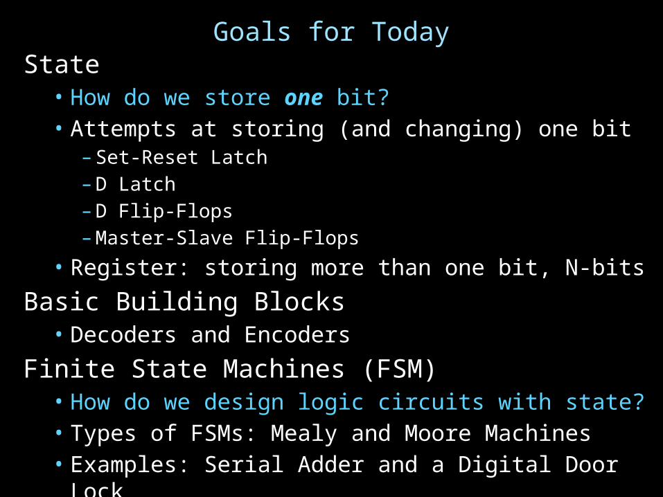
First Attempt: Unstable Devices
B
A
C

Second Attempt: Bistable Devices
A B A Simple Device
• Stable and unstable equilibria?

BR
Third Attempt: Set-Reset Latch
Q
Q
AS
Can you store a value (with this circuit)?Can you change its value?
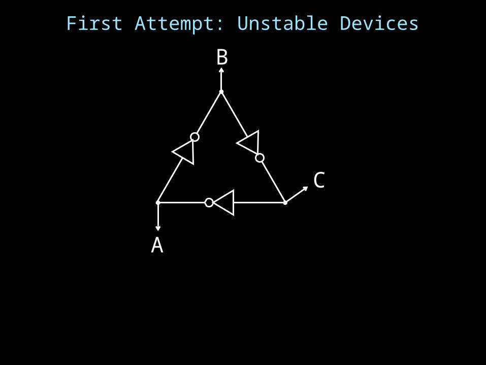
Third Attempt: Set-Reset Latch
Set-Reset (S-R) LatchStores a value Q and its complement
S R Q
0 0
0 1
1 0
1 1
S
R
Q
Q
A B OR NOR
0 0 0 1
0 1 1 0
1 0 1 0
1 1 1 0

Third Attempt: Set-Reset Latch
Set-Reset (S-R) LatchStores a value Q and its complement
S R Q
0 0
0 1
1 0
1 1
S
R
Q
Q
A B OR NOR
0 0 0 1
0 1 1 0
1 0 1 0
1 1 1 0
S
R
Q
Q
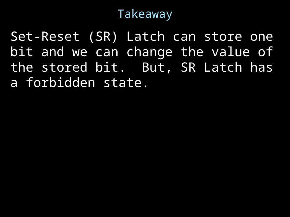
Takeaway
Set-Reset (SR) Latch can store one bit and we can change the value of the stored bit. But, SR Latch has a forbidden state.
Next GoalHow do we avoid the forbidden state of S-R Latch?

Fourth Attempt: (Unclocked) D Latch
Fill in the truth table?
DS
R
Q
Q
D
D Q
0
1
S
R
Q
Q
A B OR NOR
0 0 0 1
0 1 1 0
1 0 1 0
1 1 1 0

Takeaway
Set-Reset (SR) Latch can store one bit and we can change the value of the stored bit. But, SR Latch has a forbidden state.
(Unclocked) D Latch can store and change a bit like an SR Latch while avoiding the forbidden state.

Next GoalHow do we coordinate state changes to a D Latch?

ClocksClock helps coordinate state changes
• Usually generated by an oscillating crystal• Fixed period; frequency = 1/period
1
0clockperiod
clockhigh
clocklow
risingedgefalling
edge
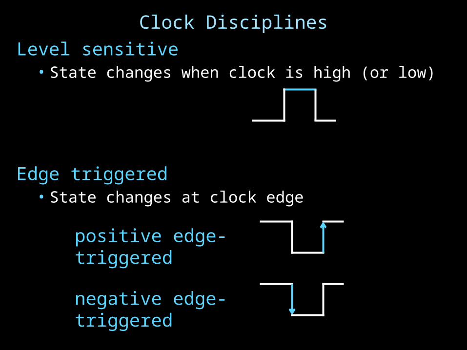
Clock DisciplinesLevel sensitive
• State changes when clock is high (or low)
Edge triggered• State changes at clock edge
positive edge-triggered
negative edge-triggered

Clock MethodologyClock Methodology•Negative edge, synchronous
– Edge-Triggered: Signals must be stable near falling clock edge
•Positive edge synchronous
clk
compute save
tsetup thold
compute save compute
tcombinational

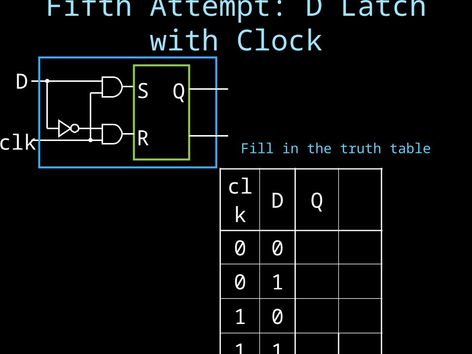
Fifth Attempt: D Latch with Clock
S
R
D Q
Q
Fifth Attempt: D Latch with Clock
S
R
D
clk
Q
Q
clk D Q
0 0
0 1
1 0
1 1
Fill in the truth table

clk D Q
0 0
0 1
1 0
1 1
Fifth Attempt: D Latch with Clock
S
R
D
clk
Q
Q
S R Q
0 0 Q hold
0 1 0 1 reset
1 0 1 0 set
1 1 forbidden
clk D Q
0 0
0 1
1 0
1 1
Fill in the truth table

Fifth Attempt: D Latch with Clock
S
R
D
clk
Q
Q
clk D Q
0 0
0 1
1 0
1 1
clk
DQ
Fill in the truth table
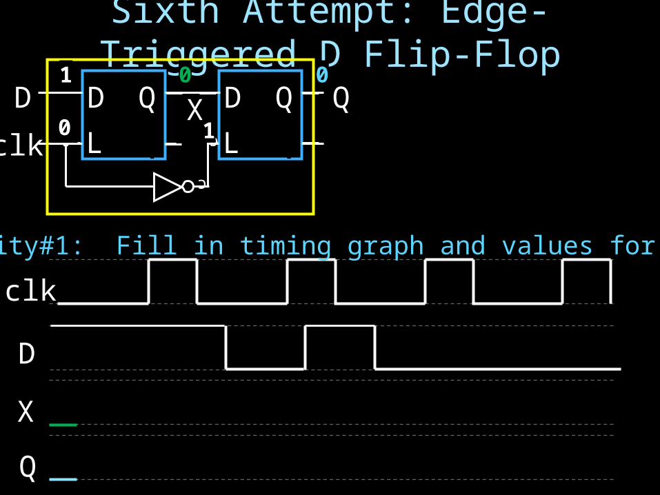
Sixth Attempt: Edge-Triggered D Flip-Flop
D Q
QD Q
QL L
clk
D
X
Q
c
X
c
Q
QD
clk0
0
1
01
Activity#1: Fill in timing graph and values for X and Q
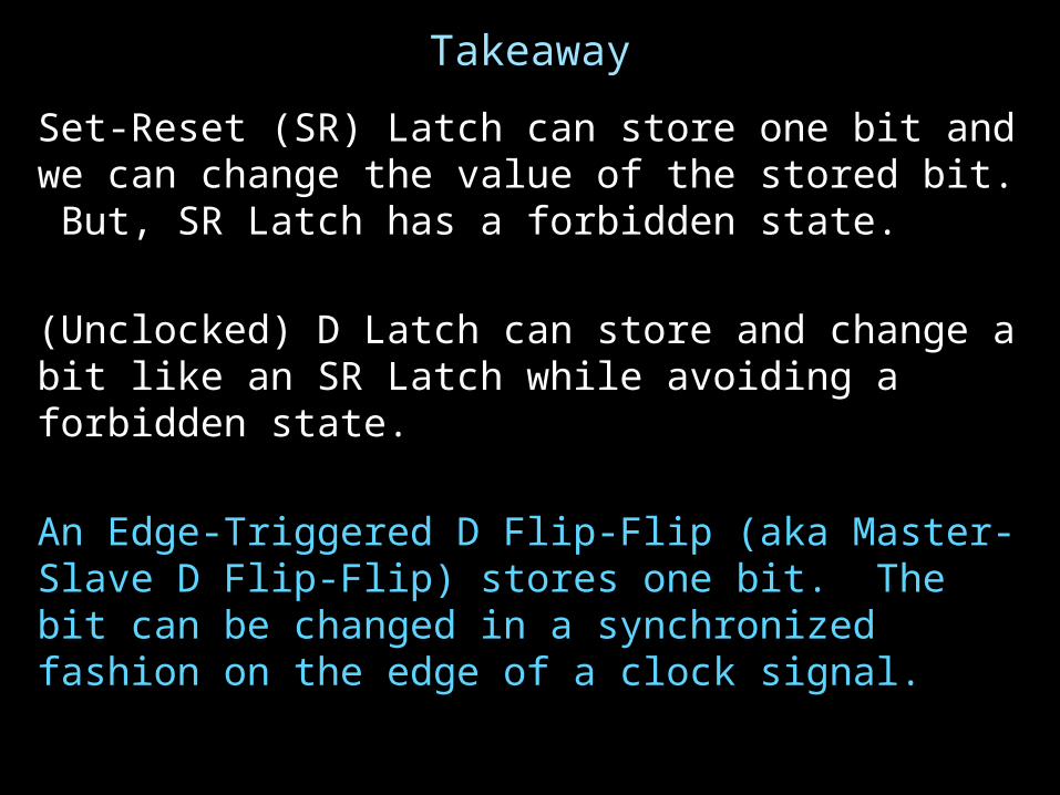
Takeaway
Set-Reset (SR) Latch can store one bit and we can change the value of the stored bit. But, SR Latch has a forbidden state.
(Unclocked) D Latch can store and change a bit like an SR Latch while avoiding a forbidden state.
An Edge-Triggered D Flip-Flip (aka Master-Slave D Flip-Flip) stores one bit. The bit can be changed in a synchronized fashion on the edge of a clock signal.
Next Goal
How do we store more than one bit, N bits?

RegistersRegister•D flip-flops in parallel •shared clock•extra clocked inputs:write_enable, reset, …
clk
D0
D3
D1
D2
4 44-bitreg
clk

Takeaway
Set-Reset (SR) Latch can store one bit and we can change the value of the stored bit. But, SR Latch has a forbidden state.
(Unclocked) D Latch can store and change a bit like an SR Latch while avoiding a forbidden state.
An Edge-Triggered D Flip-Flip (aka Master-Slave D Flip-Flip) stores one bit. The bit can be changed in a synchronized fashion on the edge of a clock signal.An N-bit register stores N-bits. It is be created with N D-Flip-Flops in parallel along with a shared clock.
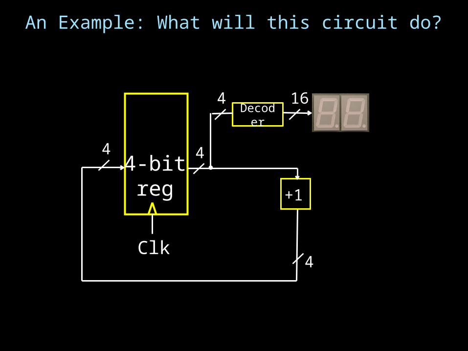
An Example: What will this circuit do?
4-bitreg
Clk
Decoder
+1
4
4 4
164

Decoder Example: 7-Segment LED 7-Segment LED
• photons emitted when electrons fall into holes
d7 d6 d5 d4
d3 d2 d1 d0
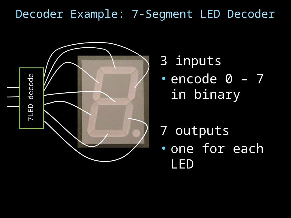
Decoder Example: 7-Segment LED Decoder
3 inputs • encode 0 – 7 in
binary
7 outputs• one for each LED
7LED
dec
ode

b2 b1 b0 d6 d5 d4 d3 d2 d1 d0
0 0 0
0 0 1
0 1 0
0 1 1
1 0 0
1 0 1
1 1 0
1 1 1
7 Segment LED Decoder Implementation
d0d1
d2d3
d4d5
d6
b2 b1 b0 d6 d5 d4 d3 d2 d1 d0
0 0 0
0 0 1
0 1 0
0 1 1
1 0 0
1 0 1
1 1 0
1 1 1

7 Segment LED Decoder Implementation
d0d1
d2d3
d4d5
d6
b2 b1 b0 d6 d5 d4 d3 d2 d1 d0
0 0 0
0 0 1
0 1 0
0 1 1
1 0 0
1 0 1
1 1 0
1 1 1
1 1 1 0 1 1 1
1 0 0 0 0 0 1
0 1 1 1 0 1 1
1 1 0 1 0 1 1
1 0 0 1 1 0 1
1 1 0 1 1 1 0
1 1 1 1 1 1 0
1 0 0 0 0 1 1

Basic Building Blocks We have Seen
binaryencoder
2N
N binarydecoder
N
2N
Mul
tiple
xor
N
M
N
N
N
N
. . .
0
1
2
2M-1
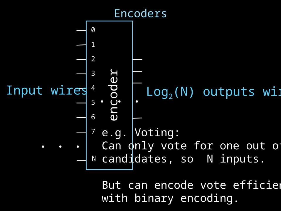
Encoders
1
2
3
4
5
6
7
0
enco
der
N
. . .
. . .
Log2(N) outputs wiresN Input wires
e.g. Voting:Can only vote for one out of N candidates, so N inputs.
But can encode vote efficiently with binary encoding.

Example Encoder Truth Table
a
b
1
c
d
2
3
4
o1
A 3-bitencoder
with 4 inputsfor simplicity
a b c d
0 0 0 0
1 0 0 0
0 1 0 0
0 0 1 0
0 0 0 1
o0
o1
o2
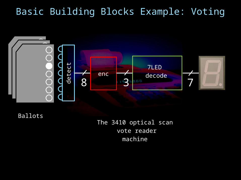
Basic Building Blocks Example: Voting
BallotsThe 3410 optical scan
vote readermachine
dete
ctenc
8 3 7
7LED decode

RecapWe can now build interesting devices with sensors
• Using combinatorial logic
We can also store data values (aka Sequential Logic)• In state-holding elements• Coupled with clocks
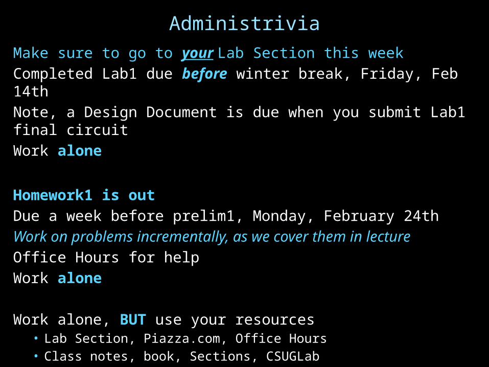
AdministriviaMake sure to go to your Lab Section this weekCompleted Lab1 due before winter break, Friday, Feb 14thNote, a Design Document is due when you submit Lab1 final circuitWork alone
Homework1 is outDue a week before prelim1, Monday, February 24thWork on problems incrementally, as we cover them in lectureOffice Hours for helpWork alone
Work alone, BUT use your resources• Lab Section, Piazza.com, Office Hours• Class notes, book, Sections, CSUGLab

Administrivia
Check online syllabus/schedule •http://www.cs.cornell.edu/Courses/CS3410/2014sp/schedule.htmlSlides and Reading for lecturesOffice HoursHomework and Programming AssignmentsPrelims (in evenings):
• Tuesday, March 4th • Thursday, May 1th
Schedule is subject to change
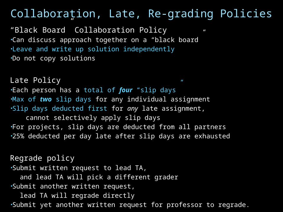
Collaboration, Late, Re-grading Policies“Black Board” Collaboration Policy•Can discuss approach together on a “black board”•Leave and write up solution independently•Do not copy solutions
Late Policy•Each person has a total of four “slip days”•Max of two slip days for any individual assignment•Slip days deducted first for any late assignment, cannot selectively apply slip days•For projects, slip days are deducted from all partners •25% deducted per day late after slip days are exhausted
Regrade policy•Submit written request to lead TA,
and lead TA will pick a different grader •Submit another written request,
lead TA will regrade directly •Submit yet another written request for professor to regrade.

Goals for TodayState
• How do we store one bit?• Attempts at storing (and changing) one bit
– Set-Reset Latch– D Latch– D Flip-Flops– Master-Slave Flip-Flops
• Register: storing more than one bit, N-bits
Basic Building Blocks• Decoders and Encoders
Finite State Machines (FSM)• How do we design logic circuits with state?• Types of FSMs: Mealy and Moore Machines• Examples: Serial Adder and a Digital Door Lock

Finite State Machines
Next Goal
How do we design logic circuits with state?

Finite State Machines
An electronic machine which has• external inputs• externally visible outputs• internal state
Output and next state depend on• inputs• current state
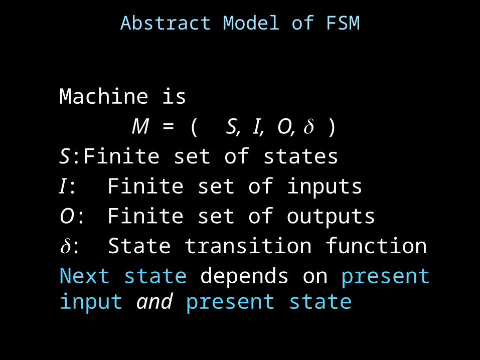
Abstract Model of FSM
Machine isM = ( S, I, O, )
S: Finite set of statesI: Finite set of inputsO: Finite set of outputs: State transition functionNext state depends on present input and present state

Automata Model
Finite State Machine
• inputs from external world• outputs to external world• internal state• combinational logic
Next State
Current State
Input
Output
Regi
ster
sComb.Logic

FSM Example
Legend
state
input/output
startstate
A B
C D
down/onup/off down/on
down/off
up/off
up/off
down/offup/off
Input: up or downOutput: on or offStates: A, B, C, or D

FSM Example
Legend
state
input/output
startstate
A B
C D
down/onup/off down/on
down/off
up/off
up/off
down/offup/off
Input: = up or = downOutput: = on or = offStates: = A, = B, = C, or = D

FSM Example
Legend
S1S0
i0i1i2…/o0o1o2…
S1S0
00 01
10 11
1/10/0 1/1
1/0
0/0
1/0
0/00/0
Input: 0=up or 1=downOutput: 1=on or 1=offStates: 00=A, 01=B, 10=C, or 11=D

General Case: Mealy Machine
Outputs and next state depend on bothcurrent state and input
Mealy Machine
Next State
Current State
Input
OutputRe
gist
ers
Comb.Logic
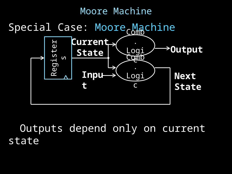
Moore Machine
Special Case: Moore Machine
Outputs depend only on current state
Next State
Current State
Input
OutputRe
gist
ers Comb.Logic
Comb.Logic
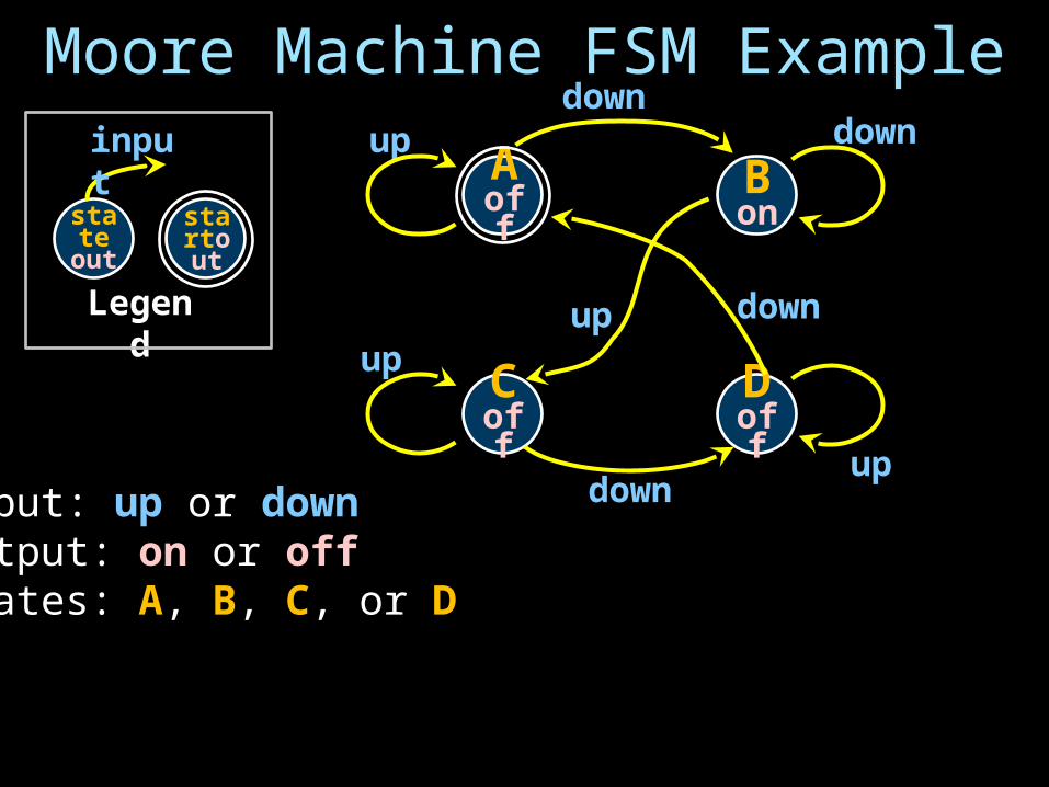
Moore Machine FSM Example
Legend
stateout
input
startout
A off
Bon
C off
D off
downup down
down
up
up
downup
Input: up or downOutput: on or offStates: A, B, C, or D

Mealy Machine FSM Example
Legend
state
input/output
startstate
A B
C D
down/onup/off down/on
down/off
up/off
up/off
down/offup/off
Input: up or downOutput: on or offStates: A, B, C, or D
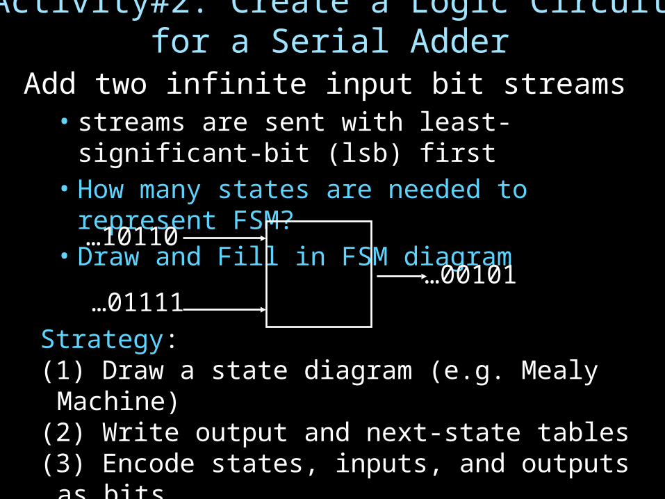
Activity#2: Create a Logic Circuit for a Serial Adder
Add two infinite input bit streams• streams are sent with least-significant-bit (lsb) first• How many states are needed to represent FSM?• Draw and Fill in FSM diagram
…10110
…01111…00101
Strategy:(1) Draw a state diagram (e.g. Mealy Machine)(2) Write output and next-state tables(3) Encode states, inputs, and outputs as bits(4) Determine logic equations for next state and outputs

FSM: State Diagram
states:Inputs: ??? and ???Output: ???
• .
…10110
…01111…00101

FSM: State Diagram
states:Inputs: ??? and ???Output: ???
• .
S0 S1__/_ __/_
__/_
__/_
__/___/_
__/_
__/_
…10110
…01111…00101
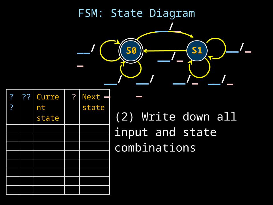
FSM: State Diagram
??
?? Current state
? Next state
(2) Write down all input and state combinations
S0 S1__/_ __/_
__/_
__/_
__/___/_
__/_
__/_
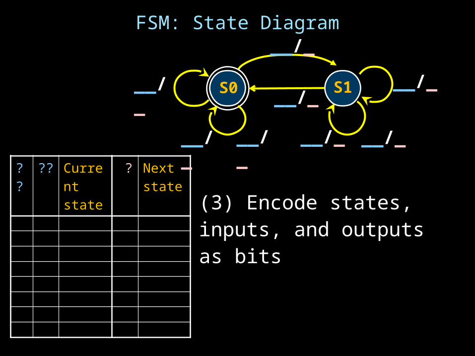
FSM: State Diagram
??
?? Current state
? Next state
(3) Encode states, inputs, and outputs as bits
S0 S1__/_ __/_
__/_
__/_
__/___/_
__/_
__/_
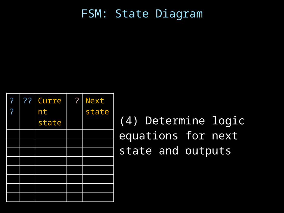
FSM: State Diagram
??
?? Current state
? Next state
(4) Determine logic equations for next state and outputs

Summary
We can now build interesting devices with sensors• Using combinational logic
We can also store data values• Stateful circuit elements (D Flip Flops, Registers, …)• Clock to synchronize state changes• State Machines or Ad-Hoc Circuits

![Memory - Cornell University€¦ · Memory [Weatherspoon, Bala, Bracy, and Sirer] Prof. Hakim Weatherspoon. CS 3410. Computer Science. Cornell University](https://img.dokumen.tips/doc/110x75/60936e5918f3ac3bab24a7fb/memory-cornell-memory-weatherspoon-bala-bracy-and-sirer-prof-hakim-weatherspoon.jpg)


![Hakim Weatherspoon CS 3410 · 2020-01-08 · Calling Conventions Hakim Weatherspoon CS 3410. Computer Science. Cornell University [Weatherspoon, Bala, Bracy, McKee and Sirer]](https://img.dokumen.tips/doc/110x75/5f96a8e542e1ef67bd47302f/hakim-weatherspoon-cs-2020-01-08-calling-conventions-hakim-weatherspoon-cs-3410.jpg)


![Introduction - Cornell University · Introduction [Weatherspoon, Bala, Bracy, and Sirer] Prof. Hakim Weatherspoon CS 3410 Computer Science ... programming the IBM 7090 Mary Jackson](https://img.dokumen.tips/doc/110x75/5f09a7e57e708231d427e191/introduction-cornell-introduction-weatherspoon-bala-bracy-and-sirer-prof.jpg)