Embed Size (px)
Citation preview

07/01/02 11.43 DIDACT_EN01.DOC 1/42
TutorialMillenium 2
Contents
PRODUCTS.......................................................................................................................................................3
2 ENVIRONMENT:........................................................................................................................................3
2.1 YOUR PC RESOURCES: ..........................................................................................................................32.2 INSTALLING THE SOFTWARE WORKSHOP................................................................................................32.3 CONNECTION TO THE PC........................................................................................................................3
3 FAMILIARIZATION ....................................................................................................................................4
3.1 ACCESSING HELP ...................................................................................................................................43.2 TOOLBARS...............................................................................................................................................43.3 THE FUNCTION BAR.................................................................................................................................43.4 MENUS ....................................................................................................................................................5
4 FUNCTIONS................................................................................................................................................5
4.1 INPUTS:....................................................................................................................................................54.2 OUTPUTS .................................................................................................................................................74.3 FUNCTION BLOCKS / FBD (FUNCTION BLOCK DIAGRAM)......................................................................74.4 GRAFCET / SFC (SEQUENTIAL FUNCTION CHART) .............................................................................154.5 BACKLIGHTING THE DISPLAY.................................................................................................................15
5 STARTING AN APPLICATION..............................................................................................................16
5.1 THE WIRING PAGE .................................................................................................................................165.2 EDITING YOUR PROGRAM: EDIT MODE .................................................................................................18
5.2.1 Supervision......................................................................................................................................195.2.2 Import................................................................................................................................................19
5.3 TESTING YOUR PROGRAM: SIMULATION MODE ....................................................................................195.3.1 Front panel display .........................................................................................................................195.3.2 Simulation mode parameters........................................................................................................19
5.4 WRITING TO THE MILLENIUM AND RUNNING..........................................................................................205.5 MONITORING MODE ...............................................................................................................................205.6 PRINTING YOUR APPLICATION ...............................................................................................................21
6 MILLENIUM IN RUN MODE...................................................................................................................21
6.1 THE DISPLAY: ........................................................................................................................................21 ACCESSING THE MENU...................................................................................................................................226.3 MENU STRUCTURE ................................................................................................................................226.4 RUN/STOP.............................................................................................................................................23
6.4.1 Accessing the menu with a password..........................................................................................236.5 SETTING THE DATE AND TIME................................................................................................................23
6.5.1 Setting the time on the Millenium from the software workshop ...............................................236.5.2 Setting the time on the Millenium from the front panel .............................................................246.5.3 Calibration........................................................................................................................................24
6.6 VALUES IN THE BLOCKS WHICH CAN BE MODIFIED................................................................................246.7 MODIFYING A VALUE BY SELECTING FBD BLOCKS...............................................................................256.8 MODIFYING A VARIABLE USING DISPLAY BLOCKS. ................................................................................26

07/01/02 11.43 DIDACT_EN01.DOC 2/42
FAULT.............................................................................................................................................................27
7 PASSWORD FUNCTION........................................................................................................................28
7.1 YOU HAVE LOST YOUR PASSWORD.......................................................................................................28
8 FRONT PANEL LOCK............................................................................................................................28
8.1 UNLOCKING THE FRONT PANEL.............................................................................................................28
9 PASSWORD AND FRONT PANEL LOCK: ........................................................................................28
10 MEMORY MODULE.................................................................................................................................29
10.1 SAVING A CONTROLLER PROGRAM TO THE MODULE ............................................................................2910.1.1 Save without front panel lock.....................................................................................................2910.1.2 Save with front panel lock ..........................................................................................................29
10.2 TRANSFERRING A MODULE PROGRAM TO THE MILLENIUM ...................................................................2910.2.1 Sequence......................................................................................................................................2910.2.2 The front panel is locked ............................................................................................................2910.2.3 The Millenium program is protected by a password ..............................................................2910.2.4 The controller program is protected by a password and the front panel is locked ...........30
10.3 COMMENTS ON USING THE MEMORY MODULE ......................................................................................3010.4 EXAMPLE OF USING THE MEMORY MODULE ..........................................................................................30
11 APPLICATION-SPECIFIC FUNCTIONS..............................................................................................30
11.1 APPLICATION-SPECIFIC FUNCTION IN THE SOFTWARE WORKSHOP ......................................................3011.2 APPLICATION-SPECIFIC FUNCTION IN THE MILLENIUM ..........................................................................31
11.2.1 Reading application-specific functions present in the Millenium. The Millenium isconnected to the workshop. ....................................................................................................................31
11.3 MADE-TO-ORDER APPLICATION-SPECIFIC FUNCTION ...........................................................................31
12 MODEM FUNCTION................................................................................................................................32
12.1 DESCRIPTION/WIRING...........................................................................................................................3212.2 SETUP ...................................................................................................................................................32
13 APPLICATION WITH EXTENSION ......................................................................................................36
13.1 XT 20 + XC ADJACENT EXTENSION.....................................................................................................3613.2 XT 20 + XT 20 + ADJACENT EXTENSION: ..........................................................................................38
NETWORKS ....................................................................................................................................................41
14.1 AS_I SLAVE EXTENSION ........................................................................................................................4114.2 MODBUS SLAVE EXTENSION..................................................................................................................42
07/01/02 11.43 DIDACT_EN01.DOC 3/42
TUTORIALMillenium 2
1 PRODUCTSCongratulations on purchasing one of the following products:
2 ENVIRONMENT:MILLENIUM 2 is programmed using the Cls M2 software workshop. It should therefore beconnected to your PC.
2.1 Your PC resources:
PC Pentium 166 MHz minimum; 32 Mb of RAM memory. SVGA (800x 600) screen with 256 coloursminimum. 65536 recommended. Windows 9x or Windows NT4.0 SP5 operating system.Disk space required 32 Mb.
2.2 Installing the software workshop.
Insert the Millenium 2 CD and follow the instructions. You can perform as many installations asthere are languages (English, French, German, Italian, Spanish).
2.3 Connection to the PCConnection should be made to the serial port of your PC via the 88 950 102 cable.
.
PC
Cable Memorycartridge
Internalextension
Externalextension

07/01/02 11.43 DIDACT_EN01.DOC 4/42
3 FAMILIARIZATION
3.1 Accessing HelpThe CLS 2 software workshop Help is accessible from the menu bar by clicking on ? then Help.
Help is also available in the function windows.
3.2 Toolbars
The toolbars contain shortcuts to elements in the menu. A description of the toolbar icons can befound in the help. Click ? then Help; select edit window then select a menu element.
The controller toolbar:This is used to manage actions on the Millenium and also to select the application mode (editing,supervision, monitoring). Pausing the cursor on the button icon displays the action associated withthe button.
3.3 The function barThe function bar contains all the Millenium functions.
The function bar tool isused to show or hidethe function bar.
The grid tool is used toactivate or deactivatedisplay of a grid (whosesize can be configured) onthe wiring page.
BMP\Interface\aide.bmp

07/01/02 11.43 DIDACT_EN01.DOC 5/42
3.4 Menus
See Help: select the ? menu then Help. Click on Edit window.
4 FUNCTIONS
4.1 Inputs:Note: The following descriptions are illustrated with working examples. Double-click on the file iconto open the application, then select simulation mode.
DI (Digital Input): (On/Off).
• See Help: double-click on the block and click on ?
AI (Analogue Input): This type of input can take an input voltage of 0 to 10 Vcorresponding to a value of 0 to 255.
♦ See Help: double-click on the block and click on ?
DI.pm2
AI.pm2
DI.pm2
07/01/02 11.43 DIDACT_EN01.DOC 6/42
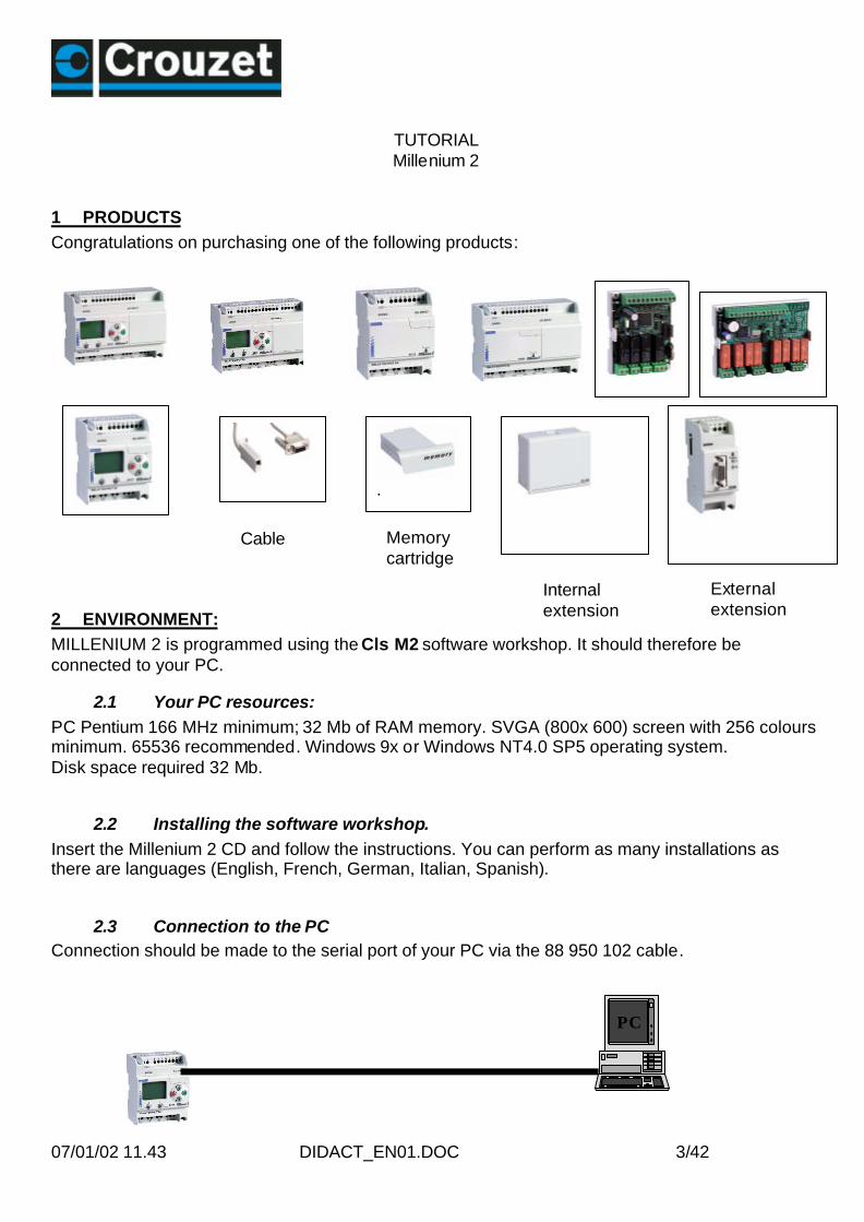
NUM IN: These inputs are only used in cases where your controller is an XT20 and isusing an extension. For example, it is possible to use these inputs to communicate a countervalue to the extension.
• See Help: double-click on the block and click on ?
Filtered inputs: You can insert filtered digital or analogue inputs in the wiring. Thesetypes of input can be used to suppress interference.
• See Help: double-click on the block and click on ?
Constants: You can affect how the constants are wired. There are bothanalogue and digital constants.
Here is an example using two digital constants.
• See Help: double-click on the block and click on ?
1 sec: This is an internal clock with a period of one second.
• See Help: double-click on the block and click on ?
Management of a light signal which is activated when 10 products are atthe end of the line. Since the product is subject to bounce on arrival atthe sensor, the input should be filtered.
Flashingsystem
1sec.pm2
NUM.pm2
DI_1.pm2

07/01/02 11.43 DIDACT_EN01.DOC 7/42
Buttons: you can use the buttons on the front panel of theMillenium: A, B, ESC, OK, + and - in your application.
4.2 Outputs
DO Digital output: on/off output.
• See Help: double-click on the block and click on ?
PWM analogue output or solid state output selected by the workshop. The defaultfrequency of the PWM outputs is 122 Hz. This can be adjusted byselecting the block in the wiring page.
122 Hz to 1960 Hz.
• See Help: double-click on the block and click on ?
NUM OUT:These outputs are only used when your controller is an XT20 and is using an extension. Forexample, it is possible to use these outputs to communicate data to the extension.
• See Help: double-click on the block and click on ?
4.3 Function blocks / FBD (Function Block Diagram)
The Boolean function takes four inputs. The output reacts according to the truth tabledescribed in the parameters.
To access the boolean function parameters, simply double-click on the block or right-click andselect the parameter-setting window.
• See Help: double-click on the block and click on ?
Creation of anexclusive OR gateon four inputs
PROGRAM
ABescOK.pm2
PWM.pm2
BOULEAN.pm2

07/01/02 11.43 DIDACT_EN01.DOC 8/42
Rocker switch: This is an element consisting of two inputs: R and S. R for Reset andS for Set. To activate the output, simply generate a pulse on S; to deactivate it, generate a pulse onR. The priority defines the output state when both inputs are at 1.
• See Help: double-click on the block and click on ?
Time delay: This is used to apply an ON delay, an OFF delay, or both delays to theoutput signal in relation to the input signal. This block can be used to make a function A orfunction C timer.
• See Help: double-click on the block and click on ?
Counter: This function is used to count up to a value defined in the parameter-settingwindow. Once this value has been reached, the output changes to 1 until reset if the fixed output isselected or for a certain period if the pulse output is selected. The count value and the maximumvalue can be displayed.The user has the option of counting from zero to the defined value or from the defined value to zero.
• See Help: double-click on the block and click on ?
This is a motor controlled bya run button and a stop button
In this example you can see how tocreate a timer
Here is a conveyor carrying parts to be packed. After every5 parts, the conveyor stops and the operator packs theparts. Then he presses the button again to reset the counterand thus restart the conveyor.
Input
Function A
Function C
Function ACt
t
t
t
SET RESET.pm2
TIMER A_C.pm2
PRESET COUNT.pm2

07/01/02 11.43 DIDACT_EN01.DOC 9/42
Zone comparison: Used for applications using analogue data.
• See Help: double-click on the block and click on ?
Display on the LCD: This block is used to display text or an integer on the LCDdisplay on the controller front panel. For example, you can display a decimal derived from aninteger. For more details, please refer to the example.
Run in thezone
Max. limit
Min. limit
Output
Input
Stop in thezone
Checking a voltage.If the voltage is >6V or <4Vthen the bell rings
This is an example of using the controllerLCD. The date, time, text and a decimalvalue is displayed on it from an integer.
VAL.pm2
LCD.pm2

07/01/02 11.43 DIDACT_EN01.DOC 10/42
The display function is used to display text, variables, the time or the date on the Millenium display.The function window is used to display the variable with decimal places and to edit text .
In this example 4 display blocks are used; here B00 is selected, which displays the content of the variable B01; here a display of 1/1000 hasbeen chosen by selecting this radio button.
Display Blocks
We have chosen to display this constant on line 4, starting at the Third column.
Note: Calibration compensates for drifting of the Millenium clock. If the calibration button isactivated, the display will allow modification of this value. The unit is in seconds per week.
• See Help: double-click on the block and click on ?

07/01/02 11.43 DIDACT_EN01.DOC 11/42
Schmitt trigger: The output changes state if the input is lower than the minimumvalue, and the output changes state again if the input is higher than the maximum value. If the inputis between the two, the output remains unchanged.
This function is used to locate a high threshold and low threshold in relation to an analogue variable.
• See Help: double-click on the block and click on ?
Gain: Function which allows the use of a scale factor and is applicable to all analoguedata.
Example: This is a program which uses a counter, a comparator, a gain and the counter read-outdisplay. An alarm is activated after the sensor has been passed 20 times.
• See Help: double-click on the block and click on ?
Example of a gain function used to display the temperature measured by a PT 100 temperatureprobe between -20 and + 60°C.The measurement scale A = 80 (-20 to +60); these 80°C are divided into 256 points.The offset corresponds to -20°C; the limit display values would be 60 and -20.
You can use this function in atimer, for example.
In this example, an alarm isactivated after the sensor has beenpassed 20 times. The number ofimpulses is divided by 5.
This is an example of temp erature regulation: theheating comes on when the input is lower than acertain temp erature and goes off when this inputreaches a given temp erature.
Heating
Stop
Range: 80resolution 0 to 255Min. value -20°
Max. Temp: 60°CMin. Temp: -20°C
TRIGGER.pm2
GAIN.pm2
07/01/02 11.43 DIDACT_EN01.DOC 12/42
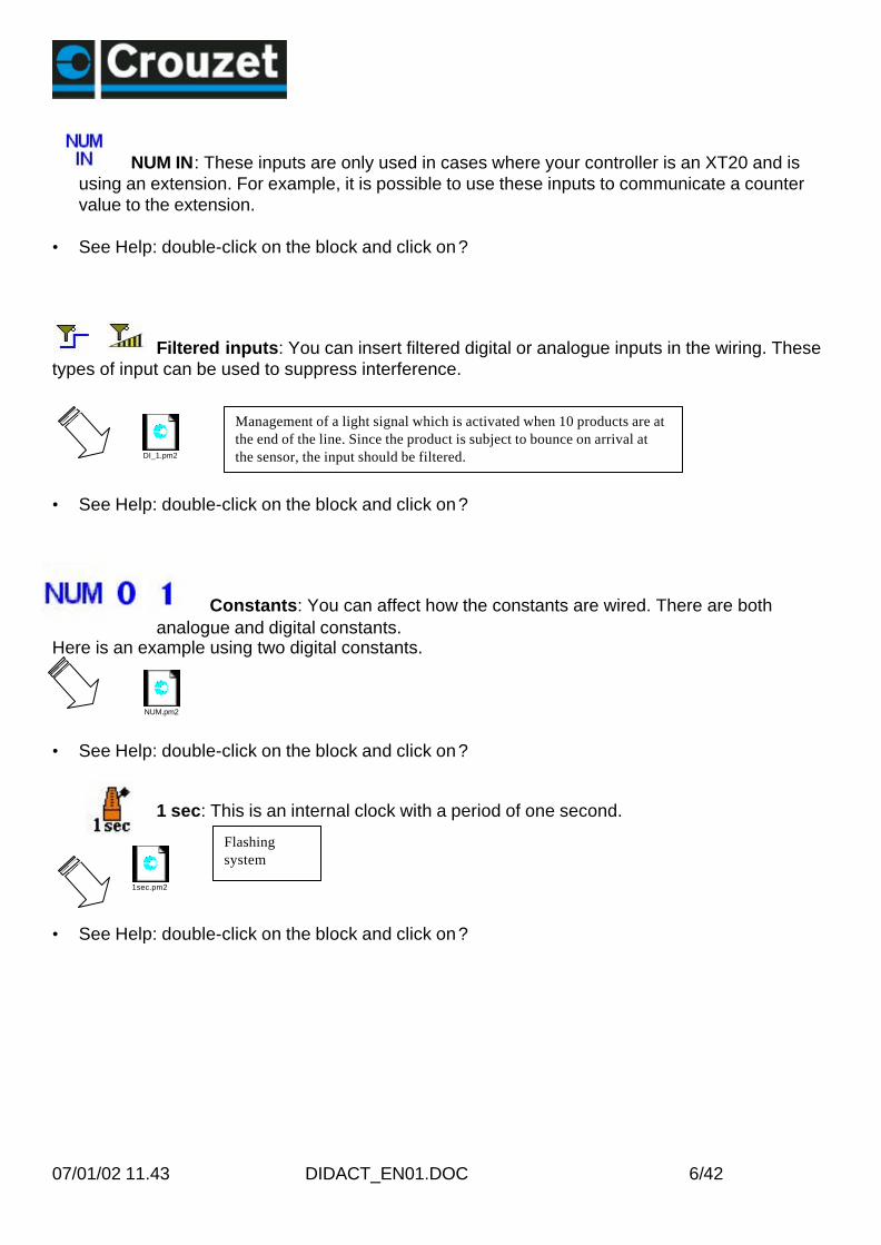
This example combines some blocks which have already been introduced in order to controltemperature and display it on the controller, using a gain function which enables the data providedby the sensor to be used.
In this example, the chosen display is 1/100°C and therefore all the parameters of the SchmittTrigger function and the Gain function should be multiplied by 100 with the exception of the 255denominator constant.
BW timer: This generates a cycle duration pulse on a rising or falling edge or on bothedges of an input, according to the setting chosen in the parameters.
• See Help: double-click on the block and click on ?
Clock: This function measures the duration of the input state at 1. After a preset duration,the output changes state. This block can, for example, be used as an alert on a machine formaintenance purposes.
If the INI on break box is checked, this means that the content of measurement will be reset after apower cut.
• See Help: double-click on the block and click on ?
Pulse: This is used to generate pulses on a rising edge of the input.
• See Help: double-click on the block and click on ?
This is the principle used to warnof the need for maintenance.Every 30 hours of operation, tochange a filter on the machine forexample.
This example shows how to makean alarm and the display flash
This block can, for example, be used to convert pushbutton actions intopulses so they can be counted. Because if several pushbuttons are connectedto a counter input and a user holds down the pushbutton, pressing the otherpushbuttons would have no effect.
Timer BW.pm2
GAIN.pm2
HH_MM.pm2
TIMER Li.pm2

07/01/02 11.43 DIDACT_EN01.DOC 13/42
Monostable: This block is used to generate a pulse (the time can be configured) on arising edge of the input.
• See Help: double-click on the block and click on ?
Comparison of two values: This block is used to compare two analogue values usingthe =, >, <, �, �, � operators. The output is digital and is activated if the comparison is true.
• See Help: double-click on the block and click on ?
This example showshow this block operatesin simulation mode
This program example is usedto activate the output if bothinputs are the same
Timer HB.pm2
COMPARE.pm2

07/01/02 11.43 DIDACT_EN01.DOC 14/42
24-hour, 7-day and 365-day timer switch: This function is used to activate ordeactivate the output at a precise moment in the day, week or year. This block works on theevent principle. To create an event, go into the parameter tab, enter an active event number.Choose the time when this event occurs, then define the state of the output at this instant.You can select the frequency of this event. You can use the calendar at the right of thescreen.
Number of programmed events.
Display event No. 1.
The summary index gives the description of programmed events.
• See Help: double-click on the block and click on ?
In this example, the timer switch isused as an alarm clock.
PRESET H-METER.pm2

07/01/02 11.43 DIDACT_EN01.DOC 15/42
To display the content of the window, select and drag the bar.
Bistable: The principle of this block is very well known, since it involves an impulserelay. An initial impulse sets the output to 1 then a second is required to change the output to 0.
4.4 Grafcet / SFC (Sequential Function Chart)
SFC functions are similar to Grafcet language. The principle is simple, since it involves sequentialprogramming, with steps succeeding one another surrounded by transitions. When a step is active,wait for the next transition to become active in order to go to the next step.
• See Help: double-click on the block and click on ?
4.5 Backlighting the display.
BK light: processed like an output. When it is active it lights up the display.
• See Help: double-click on the block and click on ?
This example shows thesequence of a program usingSFC functions.
Here this bistable is used tocontrol lighting.
BISTABLE.pm2
S F C.pm2

07/01/02 11.43 DIDACT_EN01.DOC 16/42
5 STARTING AN APPLICATION
5.1 The wiring page
Select New File and click the type of Millenium you have chosen.Select the part number corresponding to the Millenium.The wiring page opens and you are ready to build your application.The part number of the selected Millenium then appears on the wiring page.
Blocks are positioned by clicking on the block, holding down and dragging it onto the wiring page.Links between blocks are created directly by selecting block inputs and outputs. In the wiring modetool, you can choose wire as the wiring type, and you will see the links between the variouselements. If you choose text mode, the links will be marked but will no longer be visible.To change this parameter, right-click on a link and select the wiring type: wire or text.

07/01/02 11.43 DIDACT_EN01.DOC 17/42
.
wire:
text: Theconnectionsare marked
You can choose your own text: for example write SET instead of LO1. Position the cursor onLO1 then right-click with the mouse, then choose Wiring type and modify the text.When you want to move an input or output which is already assigned to an element you can movethe input or the output using the handle on the side.

07/01/02 11.43 DIDACT_EN01.DOC 18/42
It is possible to change an input or output type. This option does not affect operation.If you want to change an input or output type, simply double-click on the icon and choose an alias.On the wiring page, you can add a comment and drawings. To do this, you can use the draw toolbarand also the draw menu bar.To change the line thickness, the line colour or the background colour, you need to select theelement and click on the icon associated with the desired action in the toolbar.
5.2 Editing your program: Edit mode
The wiring page presents these three windows.
Displays the selected Millenium
By clicking title Author, you can write in the project name, date and author.By clicking Program, you can select the application cycle duration.
10 ms min. by default. Then you can choose the date format.
IIf you are using PWM (solid state) outputs, you select the frequency of all PWM outputs. (Bydefault 1960 Hz).By clicking Title you can display comments.To build your application:Select the input blocks and place them on the input terminals, select the output blocks and placethem on the output terminals.Select the function blocks, create the wiring between the various points. Double-click on thefunctions in order to set the parameters.
Each function block is numbered in the order of placing the blocks on the wiring page. Deletingblocks results in a break in the numbering. To renumber, select the blocks then Tools, Renumberfunctions.
In text mode wiring, each link is numbered in the order of placing the wiring on the wiring page.Deleting links results in a break in the numbering. To renumber, select the links then Tools,Renumber links.
Block alignment. By selecting a number of blocks, you can align them according to the icon on theDraw bar. Align left, right, … centre etc.
TitleAuthor 0.0
SA 12 R 24 VDC
PROGRAM

07/01/02 11.43 DIDACT_EN01.DOC 19/42
5.2.1 SupervisionSelect window then Supervision. Simply drag the inputs/outputs and function blocks of yourchoice from the wiring page to the supervision window. You can illustrate your application using thedraw tools. You can also choose a .BMP background image by right-clicking in the supervisionwindow; Modify background, Bitmap.This window explicitly displays the elements you have dragged from the wiring page in their ownenvironment. When you change to simulation or monitoring mode, the inputs and the outputs areupdated; it is also possible to force an input in the same way as with the edit window. Here is anexample of using supervision mode:
5.2.2 ImportYou have the option of recovering all or part of the wiring page of an existing file. To import a wiringscheme, you should already have opened a file. Select File then Import, next choose the file to beimported. When importing a wiring scheme, you will see that the previously opened file stays open.You can therefore drag a selection from the edit window of the imported wiring scheme to the editwindow of the previous wiring scheme.
5.3 Testing your program: Simulation mode
Once your program is complete , you can test it by selecting S or simulation mode.Simulation on digital or analogue inputs can be temporary or permanent. Force the input or outputby clicking on the link or on the input or output pin. It is not necessary for the controller to beconnected to the PC to perform simulation.
5.3.1 Front panel displayIn simulation mode click on Window then on Front Panel. The keys illustrated on the front panelare activated by clicking and holding down.NB: If there is a display function in your program, the menu is not accessible.
5.3.2 Simulation mode parameters
The monitoring/simulation bar is used to change the number of cycles executed at each simulationstage, and is similar to a time multiplier. Moreover, the refresh period is the frequency at which theoutput and parameter values are updated in the application windows
PIN PON.pm2

07/01/02 11.43 DIDACT_EN01.DOC 20/42
5.4 Writing to the Millenium and running
Once your application has been debugged, you can transfer it to the Millenium.The procedure is as follows:
-Stop the program-Write to the Millenium-Select run
To write data to the controller, it must be in stop mode. To send a program to the Millenium, go intothe controller menu, then click on write to the controller. The following window appears:
To lock the front panel and prevent the user from accessing the menu, check this box.§9
To protect the programwith a password, check this box.
5.5 Monitoring modeThe controller is then connected to the PC.This mode has the same characteristics as simulation mode. The state of any Millenium input oroutput can be displayed or changed from the software workshop. These inputs are visible from theedit window and the supervision window. The front panel is used to monitor the process andoperate the keys remotely by selecting the front panel window.

07/01/02 11.43 DIDACT_EN01.DOC 21/42
5.6 Printing your applicationYou can print out a complete application listing. Select File, Printer configuration.Select the required parameters.
Before printing, select File, Print preview
To modify the page orientation, or
Select File, Print and select the page format in your printer properties window.
6 MILLENIUM IN RUN MODE
6.1 The display:Default screen for a Millenium without extension.If no “Display” function is used, the Millenium displays the state of the inputs, the state of theoutputs, the date, the time and the diagnostic icons.

07/01/02 11.43 DIDACT_EN01.DOC 22/42
Run modeFixed when stopped,
Type of Millenium
6.2 Accessing the menu
If the front panel lock option has not been activated, you access the menu by pressing or
If there is a display function in your program, to go to the menu you should press and at the same time.
6.3 Menu structure
These are the main menus:
Active PClink
Switched on
Time anddate
or
moving whenrunningDiagnostic icons
State of the inputs
State of the inputsON or OFFState of the outputsON or OFF

07/01/02 11.43 DIDACT_EN01.DOC 23/42
6.4 Run/StopAccess the menu by pressing ESC or OK.If the Millenium is in Run mode, the icon turns and the menu says Stop.If the Millenium is stopped, the icon is steady and the menu says Run.
the values of the function blocks for which the INI option was checked will be reset
6.4.1 Accessing the menu with a passwordIn this case, the key icon is displayed.To enter the menu, type the password, using the and buttons
to vary the value of the password. You can make 5 attempts at entering the password. If you havenot managed to enter your password after 5 attempts, you can try again after waiting 30 minutes.For example, if you want to enter 1250, hold down the button and scroll rapidly until the valueis approached, then release the button and scroll slowly, pressing repeatedly until you reach 1250.Then press OK.
6.5 Setting the date and timeTo ensure that the programs work correctly with time-based programming, the date and the timemust be set accurately and this section shows you how to do this.
6.5.1 Setting the time on the Millenium from the software workshopFrom the software workshop: Go to the Controller menu and you can then select Read/Write dateand time. You are then presented with the following dialogue box:
The Millenium time is displayed by default; you can modify this time if you wish and then send it tothe controller. The new time is then recognised by the controller.

07/01/02 11.43 DIDACT_EN01.DOC 24/42
6.5.2 Setting the time on the Millenium from the front panel
To select a value to modify, you can browse using the + and – keys. To modify a value, select itthen press OK. You can then modify the value by pressing the and keys and finallyconfirm with OK.
6.5.3 Calibration
Calibration compensates for drifting of the clock. The unit is in seconds per week. To modify thisvalue, go into the timesetting menu then select the calibration value. To modify it, press OK, then tochange the value press the + or – keys and confirm with OK.
6.6 Values in the blocks which can be modifiedIt is possible to modify block parameters such as analogue constant, counter, timer, pulse,programmer etc. directly from the controller front panel in the 2 ways described below: by selectingthe function block or via the display function.
If you have a Millenium connected to the workshop, you can download this program to theMillenium.
Important: Make sure that the type of Millenium selected in the workshop is the same as the oneyou are using. Check this by clicking on tools then choose the type of controller.
Click on controller then on write to the controller to modify the parameters. Click run.
First of all, go into themain menu. To dothis, press OK orESC. If the passwordis required, enter it.The following menu
Now, go down to CLOCK,which flashes, and confirmwith OK. The followingscreen then appears:
Press - twice so thatMISCELLANEOUS becomesthe flashing item.
EX.pm2

07/01/02 11.43 DIDACT_EN01.DOC 25/42
6.7 Modifying a value by selecting FBD blocks
To go into the configuration menu press OK or ESC. Once in the menu, select PARAMETERS. Todo this, press the key until PARAMETERS is the flashing item. This screen will then appear:
Now press OK to confirm.The black text flashes to indicate that a value has been selected. To modify it, press OK.The value flashes when it is possible to modify it.The OK key switches from one mode to the other.Note: No parameters means there is no block corresponding to the number or the block is notconfigurable.
In the example, the FBD name is B00 so you should select 000. Should you wish to select anotherconfigurable block, press . When the required number is reached, confirm with the OK button.
To browse the various parameters, select the type of parameter by pressing
to obtain the parameters. Then press OK.

07/01/02 11.43 DIDACT_EN01.DOC 26/42
In this example, time delay B function is selected and the onlyparameter is the time delay duration.
Select a new value and confirm with OK, enter a value of your choice and confirm with OK. If yourprogram is running you will hear the difference.
6.8 Modifying a variable using display blocks.In this case, the variables to be modified are wired on the Analogue input of the function block.When the modification box is checked, it is possible to modify the value.

07/01/02 11.43 DIDACT_EN01.DOC 27/42
Continuous flashing indicates the value (or one of the values)that can be modified.
Select the value to be modified with thekeys, then OK. To modify the value press the + and - keysagain. Then confirm with OK.
6.9 FaultWhen a fault is detected on the Millenium, an icon appears at the top of the display unit.You can find out the error number by going into the main menu, selecting MISCELLANEOUS andthen selecting FAULT. In this screen you can see the number of the last fault which appeared onthe Millenium.
Here is the error correspondence table:
No error 0EEP 1Clock 2Binary 50Cycle 51Operation code 52XL local extension 53XC D.C. extension 54XD1 extension 55XD2 extension 56Remote M2 57Watchdog 58

07/01/02 11.43 DIDACT_EN01.DOC 28/42
7 PASSWORD FUNCTION
The password protects access to a program. When you write your program to the Millenium, thewrite option window opens; check the box indicated here
Once the password is active, you can nolonger write to the controller nor read theprogram without knowing this password.The program is therefore protected.If you wish to access the menu and, forexample, reset the time you will beinvited to enter the password.
7.1 You have lost your passwordIf the password is accidentally lost, the only solution is to delete the program from the Millenium. Todo this, go into the controller menu then select delete the controller content. It will then bepossible to write a new program to the controller.
8 FRONT PANEL LOCKThe front panel lock function prevents any access to the menus. The lock is effective when theprogram is running, but also when it is stopped. To start or stop the program once the lock is active,you have to go via the software workshop. However, the front panel lock does not prevent use ofthe front panel buttons in a program.When you write your program to the Millenium, the write option window opens.Then simply check the “put a lock on the controller front panel“ box.
8.1 Unlocking the front panelTo unlock the front panel, rewrite the program to the Millenium without selecting the “put a lock onthe controller front panel” option.
9 PASSWORD AND FRONT PANEL LOCK:Both functions together protect access to the application program and the front panel lock preventsaccess to the Millenium.

07/01/02 11.43 DIDACT_EN01.DOC 29/42
10 MEMORY MODULEThe memory module 88 950 101 can hold a program. The Millenium can write to the module, but itcan also read a program in the cartridge.
10.1 Saving a controller program to the module
Insert the memory module into the Millenium with the front panel unlocked. Saves are performed instop mode.Save procedure:Go into the main menu by pressing the key. Select CARTRIDGE. You are offered twosolutions:
10.1.1 Save without front panel lockIn this case select SAVE.
10.1.2 Save with front panel lockSelect PROT & SAVE.
10.2 Transferring a module program to the Millenium
10.2.1 Sequence
Insert the memory module into the Millenium with the front panel unlocked. Saves are performed instop mode.Go into the main menu by pressing the key. Next select CARTRIDGE then selectRESTORE. The new program is thus saved in the cartridge.Note: the memory module can be inserted or removed with the power on.
10.2.2 The front panel is lockedTo load the program, insert the cartridge and then simply switch off the controller for a few seconds.When it is switched back on, the program in the cartridge will load automatically and will overwritethe program previously held in the Millenium without confirmation.
10.2.3 The Millenium program is protected by a password
If the program on the Millenium is protected by a password, you will need to know it in order to beable to load the program from the memory module.
07/01/02 11.43 DIDACT_EN01.DOC 30/42
10.2.4 The controller program is protected by a password and the front panel is locked
In this case, to load a program, the password for the program contained in the cartridge must be thesame as that in the Millenium for the update to take place.
10.3 Comments on using the memory moduleWriting or reading the cartridge should be done with a Millenium. You should not use the cartridge inrun mode except in cases where the Millenium has an LCD display and the front panel is not locked(in this case only, the Eeprom is only written to each time the module is switched on).The program contained in the module loads into the controller automatically except in cases wherethe Millenium has an LCD display and the front panel is not locked.
10.4 Example of using the memory moduleA manufacturer is using the Millenium controller in his machines. The products are at the endcustomer’s premises. The program contained in the controllers is protected by a password, and thefront panel has been locked to prevent customer intervention. This manufacturer makes an updateto his program. In order to avoid sending a member of staff out to every customer, he sends out amemory module by post. The customer simply has to insert the cartridge in the controller, switch offthe power for a few seconds, switch the unit on again and finally remove the cartridge. The programcontained in the cartridge should be protected by the same password as the program it is replacing.
11 APPLICATION-SPECIFIC FUNCTIONS
The application-specific function is considered to be a special function block. When installing theworkshop, you are offered the opportunity to load the application-specific functions contained in theworkshop.
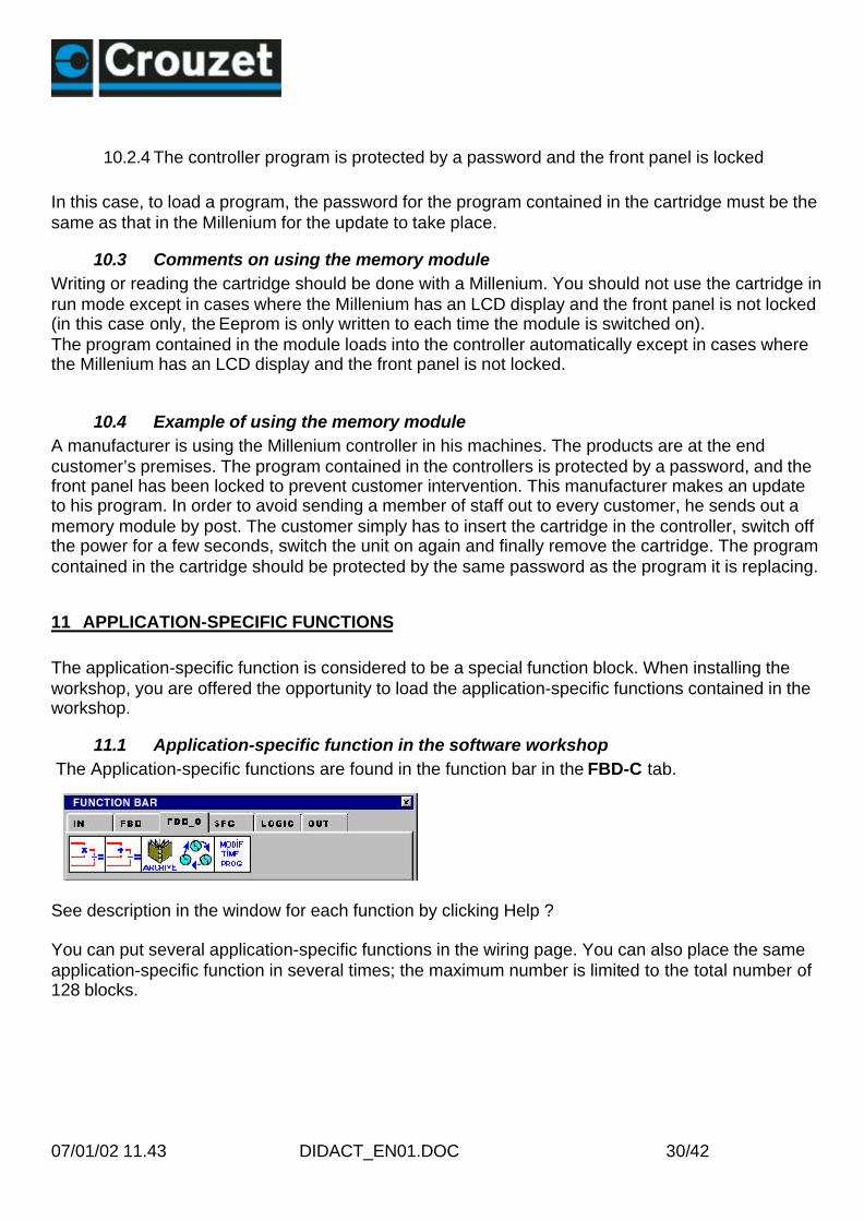
11.1 Application-specific function in the software workshop The Application-specific functions are found in the function bar in the FBD-C tab.
See description in the window for each function by clicking Help ?
You can put several application-specific functions in the wiring page. You can also place the sameapplication-specific function in several times; the maximum number is limited to the total number of128 blocks.

07/01/02 11.43 DIDACT_EN01.DOC 31/42
11.2 Application-specific function in the Millenium
The Millenium can only hold a limited number of application-specific function slots. When loading aprogram which contains 1 or more application-specific functions, you can find out the Millenium’savailability by pointing the cursor here. Availability is expressed in slots (8 in total).
Note: The number of application-specific function blocks used in the application is not linked to thenumber of slots available in the Millenium.
11.2.1 Reading application-specific functions present in the Millenium.The Millenium is connected to the workshop.Click Controller List of application-specific functions in the controller
Note: The application-specific functions stay in the Millenium even if another program is loaded inthe Millenium.
11.3 Made-to-order application-specific function
To resolve a specific application problem; please consult us for help in designing your application-specific function.
FBD-C.pm2
07/01/02 11.43 DIDACT_EN01.DOC 32/42
12 MODEM FUNCTION
12.1 Description/Wiring
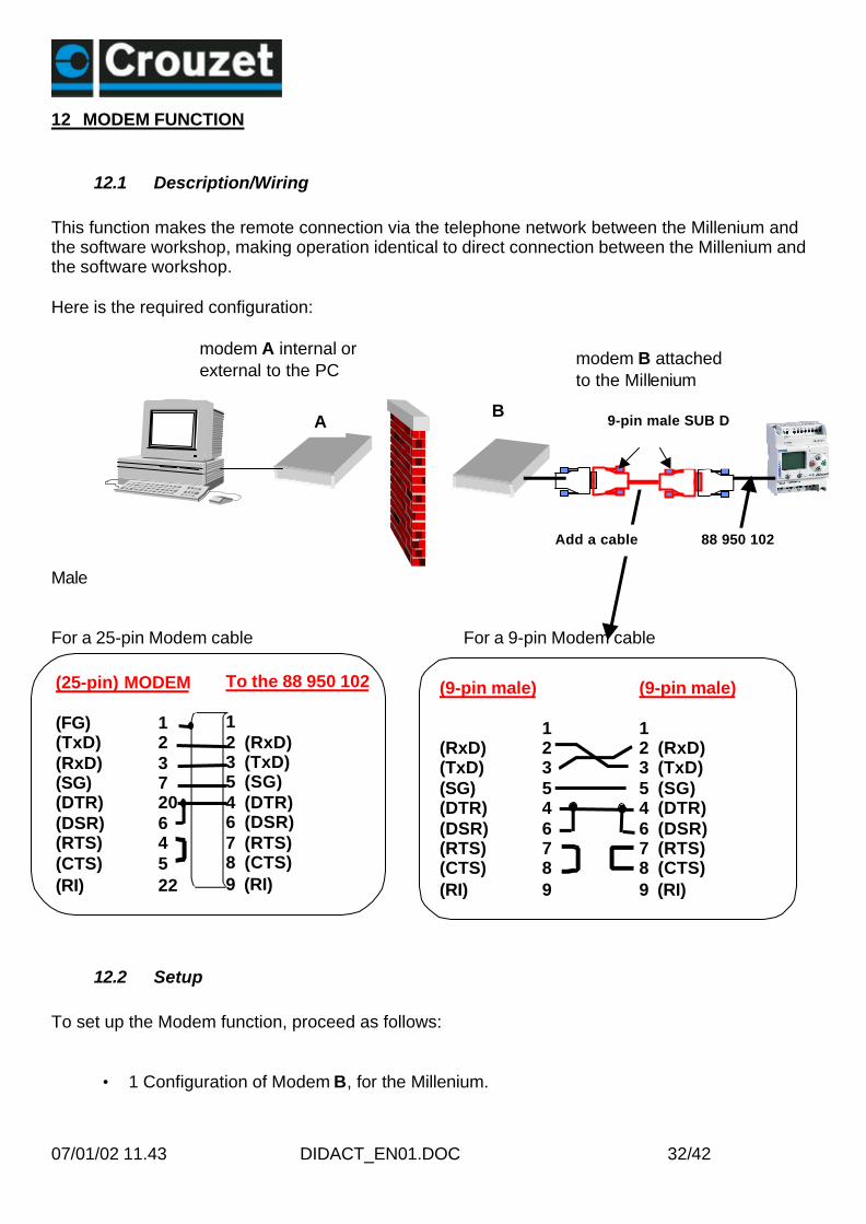
This function makes the remote connection via the telephone network between the Millenium andthe software workshop, making operation identical to direct connection between the Millenium andthe software workshop.
Here is the required configuration:
Male
For a 25-pin Modem cable For a 9-pin Modem cable
12.2 Setup
To set up the Modem function, proceed as follows:
• 1 Configuration of Modem B, for the Millenium.
modem A internal orexternal to the PC
modem B attachedto the Millenium
9-pin male SUB D
Add a cable
To the 88 950 102
12 (RxD)3 (TxD)5 (SG)4 (DTR)6 (DSR)7 (RTS)8 (CTS)9 (RI)
(25-pin) MODEM
(FG) 1(TxD) 2(RxD) 3(SG) 7(DTR) 20(DSR) 6(RTS) 4(CTS) 5(RI) 22
(9-pin male)
1(RxD) 2(TxD) 3(SG) 5(DTR) 4(DSR) 6(RTS) 7(CTS) 8(RI) 9
(9-pin male)
12 (RxD)3 (TxD)5 (SG)4 (DTR)6 (DSR)7 (RTS)8 (CTS)9 (RI)
88 950 102
AA
BA

07/01/02 11.43 DIDACT_EN01.DOC 33/42
Connect the Millenium to the software workshop; Select Controller – Connection -configure; check that PORT COM is selected and, if not, select it.
Set the Millenium to STOP modeSelect: Controller then Configure controller modemClick ChooseSelect the line corresponding to MODEM B then OK
Click OK when the window appears and configure the controller.
♦ 2. Connect the configured Millenium to Modem B
Connect Modem B to the telephone line; switch on Modem B, then the Millenium.
Power
B

07/01/02 11.43 DIDACT_EN01.DOC 34/42
♦ 3 Connect Modem A to the PC if it is external and connect the telephone line to theModem.
In order to be able to write or modify your application, the Modem should be selected in thesoftware workshop: Open an application; then click: Controller - connection - configure.
Select Modem Select the PC Modem
Type the telephone No.corresponding tothe MilleniumModem B.
Then press OKTo establish the connection with the Millenium Modem; click Controller - connection -connect in succession.
From this moment, you can perform functions such as writing, reading, monitoring, Stop,Run, Initialize
To end the communication, click Controller - connection – disconnect.
Note: When communication is established but you cannot communicate with the Millenium,check the parameter settings of Modem B on your PC (internal or external). To do this: InWindows, select Start – Settings – Control panel then double-click on Modems. Thenselect Properties and Connection to obtain this window.
Connected to remote computerDialling

07/01/02 11.43 DIDACT_EN01.DOC 35/42
Next select the followingparameters
Then OK and close.
BMP\Interface\Proprietes du modem.bmp

07/01/02 11.43 DIDACT_EN01.DOC 36/42
13 APPLICATION WITH EXTENSION
Extensions can only be used on the XT 20 models.
13.1 XT 20 + XC adjacent extensionThe adjacent extension is connected to the Millenium.You can thus connect a extension with 4 inputs/2 outputs or an AS-i exchange unit or Modbusexchange unit.
Select the type of Millenium XT 20.Then click the corresponding XC extension to add it to the Millenium.
Then select the XC adjacent extension. The extension then appears.

07/01/02 11.43 DIDACT_EN01.DOC 37/42
The type of Millenium and the extension then appear in the wiring page.
The inputs and outputs of the adjacent extension can then be seen
Title?Author 0-0
XT 20R 24 XC: XC 4E/2S 24
PROGRAM
4 inputs for theXC extension
12 inputs forthe XT 20
2 outputs for theXC extension
8 outputs forthe XT 20

07/01/02 11.43 DIDACT_EN01.DOC 38/42
13.2 XT 20 + XT 20 + adjacent extension:
The local extension is connected to the Millenium XT 20.1 Select the type of XT 20 controller with extension . then OK2 Select the type of the XC 4E/4S adjacent option,3 Then click XL to display the local extensions. OK4 Select XDO-XT20. Then OK, OK
XDO:XT20
Your whole selected configuration then appears.
M2-M2.pm2

07/01/02 11.43 DIDACT_EN01.DOC 39/42
The XT 20 A configuration is then as follows.
M2 – M2 permanent link
Wire link
TitleAuthor- 0-0
XT 20R 24 VDC
PROGRAM
XL. XL Remote XC XC 4E/2 E 24 VDC
XC XC 4E/2 E 24 VDC
XT 20R 24 VDC
XDO: XD XT20
XL. XL RemoteXDO: XD XT20
Remote B Millenium
XL. XLRemote
12 inputs forthe XT 20
8 inputbits fromB
A B
3 NUM IN inwords from B
4 inputs for theXC extension
8 outputs forthe XT 20
8 outputbits fromB
3 NUM OUTwords from B
2 outputs for theXC extension
XC XC 4E/2 E 24 VDC
XDO: XD XT20

07/01/02 11.43 DIDACT_EN01.DOC 40/42
M2-M2
In addition to the inputs and outputs of each Millenium, you can therefore exchange 8 input bits, 8output bits, 3 input words and three output words.
INPUTS
8 exchangeinput bitsand 3exchangewords
OUTPUTS
8 exchangeoutput bitsand 3exchangewords
Millenium BMillenium A
INPUTS
8 exchangeinput bitsand 3exchangewords
OUTPUTS
8 exchangeoutput bitsand 3exchangewords

07/01/02 11.43 DIDACT_EN01.DOC 41/42
14 NETWORKS
14.1 AS_i slave extensionThe AS-i extension connected to an XT 20 offers 4 input bits and 4 output bits.There are also 2 system bits and 2 control bits.
Select an XT 20, then declare the XC AS-i extension.
The AS-i slave number parameters are set by the master.Seen from the AS-i master, the AS-i master reads the state of the output bits and writes the inputbits.
Example
4 input bits
2 system bits
4 output bits
2 control bits
ASI_1.pm2

07/01/02 11.43 DIDACT_EN01.DOC 42/42
14.2 Modbus slave extension
The Modbus extension connected to an XT 20 offers 8 read bits and 3 read wordsand 8 output bits and 3 output words.
The extension Modbus parameters are set as follows: Select an XT 20, then declare the XC Modbus extension.
Click here on the Modbus extension to obtain the parameter-setting window.
Then select each of the four parameters and define them.The slave extension “speed” and “parity” parameters should be identical tothose in the master, as should the network wiring used: 2 or 4-wire.
Modbus exchanges are performed on the 8 bits and 3 words of the inputs and outputs.
modbus.pm2