Embed Size (px)
DESCRIPTION
manual
Citation preview
KODAK ONCOLOGY FILM SYSTEMS
KODAK Oncology Imaging Guide
HEALTH IMAGING
A B E T T E R V I E W O F L I F E .
PURPOSE OF THIS GUIDE
The following information is intended to be a useful guide to understanding and optimizing the use of
Kodak EC film and other films for oncology imaging. Imaging applications for Kodak EC film include
both portal localization and verification imaging. For optimum results, it is recommended that Kodak EC
film components be used together, along with Kodak film processing chemicals and equipment.
If you have any questions concerning the information contained in this guide, contact your regional
Kodak oncology manager or Kodak customer support for medical products (USA) at 1-800-328-2910
(USA area code 716-724-9362). Some of the information contained in this guide can also be seen on
the Health Imaging Web site: www.kodak.com/go/oncology.
1
HOW TO USE THIS GUIDE
This Kodak guide includes the followingsections to provide information and tohelp optimize image quality:
• Technology & historical overview
• KODAK EC film design
& applications
• Localization imaging applications
– For Cobalt 60, radiosurgery,radiotherapy, and intensity-modu-lated radiation therapy (IMRT)
• Processing KODAK EC film
• Screen cleaning and
antistatic treatment
• Compatibility of EC films with
select KODAK products
• Technical considerations and
technique recommendations for
EC-L film systems
– Using multiple energies– Image geometry – Patient thickness– Field size– Film processing
• KODAK EC-L film system
technique charts
• Simulator exposure chart
• Artifact isolation fundamentals
• Questions and answers
Selected product usage recommendationsReplenishment rates, chemistry selection, and processor selectionSafelightsWhen images are too lightWhen images are too darkGeometric factors and intermittent density variations
• Other KODAK oncology products
SIM—KODAK simulation filmPPL-2—portal pack for localizationKODAK X-OMAT radiation therapy cassettes L and V and KODAK X-OMAT
verification film (XV)KODAK EDR-2 film fordosimetry/QA/equipment calibrationOther KODAK films for direct exposure
• Other KODAK products
Film processorsPatient identification devicesFilm-handling equipment Print options
– Laser imagers– Inkjet printers
• KODAK EC-L and EC-V film systems
catalog numbers
• For more information
• Information needed by Kodak to
facilitate troubleshooting
• References
2
TECHNOLOGY & HISTORICAL OVERVIEW
History of portal imagingSome of the earliest portal images wererecorded on industrial-type, direct-expo-sure films. These films were often placedin cardboard film holders and requiredspecial processing. In 1974, EastmanKodak Company introduced films inlight-tight (Kodak Ready-Pack)envelopes for portal localization and verification. Reasonably good qualityportal images could be obtained bydirect exposure using treatmentmachines such as Cobalt 60 units (1.2 MeV) and Van de Graff generators(approximately 2 MV). However, theimage quality at higher energies was poor.
As high-energy linear acceleratorswere being introduced, studies byHammoudah and Henschke and byDroege and Bjarngard showed theimportance of using metal plates forportal imaging.1,2,3 They showed thatsome types of conventional medicalfilms could be used, depending on the film’s sensitivity to exposure by electrons. Droege and Bjarngard alsoshowed that film contrast is independentof x-ray energy and metal screen composition.2,3 They published MTF data characterizing the spatial resolution of metal plate detectors atmegavoltage energies.
Visibility of anatomical structuresand landmarks has always been difficultwhen using conventional medical x-rayfilms with higher-energy portal imaging.Such films are designed for medical radi-ography at far lower beam energies.Most screen-type medical x-ray films,regardless of their inherent film contrastlevel, exhibit very similar and very lowmeasured contrast when exposed undernon-phosphor screen exposure conditions in portal localization and
verification imaging procedures. A wide-ly used measurement of film contrast in radiographic imaging is called averagegradient. As the name indicates, thismeasurement is an average of manyindividual contrast (i.e., gradient) mea-surements along a film’s characteristiccurve or H & D curve, between specified processed film densities. Most screen-type medical x-ray filmswill produce an average gradient measurement of approximately 1.6 whenused for localization and verificationimaging without phosphor intensifyingscreens. This contrast level is well belowwhat is seen with typical low-contrast or“latitude”-type medical radiographyfilms, which have average gradients inthe vicinity of 2.1–2.4. This can makesome measurements and appropriateplacement of the treatment beam moredifficult to determine accurately.
In 1981, Du Pont introduced cassettes with lead front and back platesto be used with conventional medical x-ray film. Kodak introduced cassettes in1983 with copper front plates and leadback plates, copper front and plasticback plates, and films in light-tight(Kodak Ready-Pack) envelopes that fitinside the cassettes for portal localizationand verification imaging.
These systems gave better images at thenew higher treatment energies but thecontrast of the final image was still low.
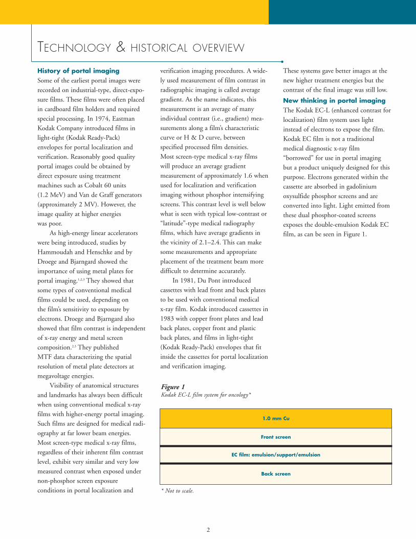
New thinking in portal imagingThe Kodak EC-L (enhanced contrast forlocalization) film system uses lightinstead of electrons to expose the film.Kodak EC film is not a traditional medical diagnostic x-ray film “borrowed” for use in portal imagingbut a product uniquely designed for thispurpose. Electrons generated within thecassette are absorbed in gadolinium oxysulfide phosphor screens and areconverted into light. Light emitted fromthese dual phosphor-coated screensexposes the double-emulsion Kodak ECfilm, as can be seen in Figure 1.
Figure 1 Kodak EC-L film system for oncology*
Back screen
EC film: emulsion/support/emulsion
1.0 mm Cu
* Not to scale.
Front screen
Kodak EC film has a characteristic curvedesigned with the unique needs of portalimaging and verification imaging inmind. Because light from phosphorintensifying screens is used to expose thefilm instead of a direct electron exposureto the film, a much different film emul-sion can be created. Using the usual filmcontrast measurement called “averagegradient” as our reference, the differ-ences are immediately clear. Typical“high-contrast,” screen-type medical x-ray films have average gradient valuesor numbers of approximately 3.0. Very-high-contrast films designed for mam-mography have average gradients ofapproximately 3.6. The average gradientof Kodak EC film is approximately 6.0,and because light instead of electronsexposes the Kodak EC film, the character-istic curve (i.e., image contrast) is similarover energies from 6 to 20 MV. Metalion “doping” of the silver-halide microcrys-tals contributes further to enabling thisvery high image display contrast level.
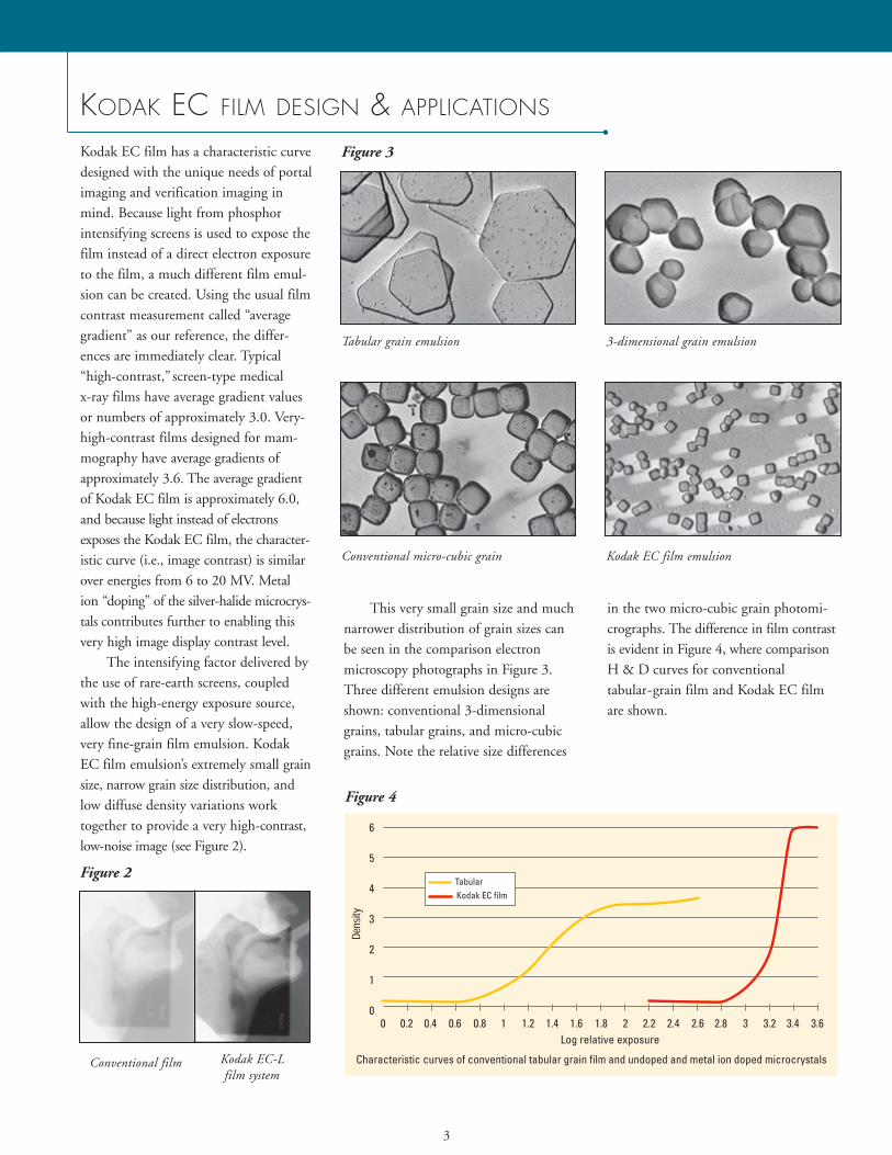
The intensifying factor delivered bythe use of rare-earth screens, coupledwith the high-energy exposure source,allow the design of a very slow-speed,very fine-grain film emulsion. KodakEC film emulsion’s extremely small grainsize, narrow grain size distribution, andlow diffuse density variations worktogether to provide a very high-contrast,low-noise image (see Figure 2).
This very small grain size and muchnarrower distribution of grain sizes canbe seen in the comparison electronmicroscopy photographs in Figure 3.Three different emulsion designs areshown: conventional 3-dimensionalgrains, tabular grains, and micro-cubicgrains. Note the relative size differences
in the two micro-cubic grain photomi-crographs. The difference in film contrastis evident in Figure 4, where comparisonH & D curves for conventional tabular-grain film and Kodak EC filmare shown.
3
KODAK EC FILM DESIGN & APPLICATIONS
Figure 4
Figure 2
Figure 3
Tabular grain emulsion 3-dimensional grain emulsion
Conventional micro-cubic grain Kodak EC film emulsion
Conventional film Kodak EC-L film system
4
KODAK EC FILM DESIGN & APPLICATIONS (continued)
Localization imaging applicationsThrough the use of different phosphorscreens with varying speeds, Kodak cassettes designed for localization imag-ing are available to fit a wide range of equipment types, energy levels, andpatient body part treatment areas. Fastercassette/film systems are ideal for fieldssuch as the lateral pelvis, for example.Slower-speed cassette/film combinationsmay be appropriate to compensate forbeam energies higher than 6 MV, partic-ularly 18 MV or higher (see Table 1).
Using KODAK EC FILM with Cobalt
60 sourcesKodak EC film can be used with Cobalt60 sources for better visualization of keylandmarks near the center of the treat-ment field. However, because of thehigh contrast of this film, the penum-bral region may be more difficult toimage with Kodak EC film.
Using KODAK EC FILM for
stereotactic radiosurgery and
radiotherapy patientsThe Kodak EC-L film system allowsunprecedented verification andenhanced quality assurance of stereotac-tic radiotherapy and radiosurgery. Thevery low image noise and high-contrastcharacteristics of Kodak EC film allowfor high-resolution, digitally scannedimages, vital to this application.Visualization of the small localizationmarkers used in stereotactic procedurescan be seen more easily. The low imagenoise of a digitized EC film allows clini-cians to utilize software tools identifyingthe 3-D position of the patient and thetreatment beam.
Using the KODAK EC-L FILM SYSTEM
for intensity-modulated
radiation therapy (IMRT)In IMRT, reproducible positioning ofthe patient can be even more importantversus traditional radiotherapy. Thesmaller field sizes allow less inclusion ofanatomy for orientation purposes andfor confirmation of treatment of thesame location identified in simulation.Portal imaging with the Kodak EC-Lfilm system can significantly increase the confidence in knowing that the immobi-lization system is working accurately,due to the significant increase in image contrast. Such improved clinical visibili-ty can mean a reduction in patient posi-tioning errors, thus improving control oftumors and reducing the risk of healthy-tissue complications.
Verification imaging applicationsThe Kodak EC-V verification systembuilds upon the innovative technologyintroduced with the Kodak EC-L filmsystem for portal localization imaging.
The difference between localizationand verification cassettes is the exposurerequired to produce an image. This isunderlined by the intended application.In verification, the imaging system willbe exposed for the entire prescribed dosefor a specific treatment field, comparedto localization that involves a short colli-mated exposure and a short open fieldexposure, to confirm patient position-ing. Thus the verification systems mustnecessarily be much slower than localiza-tion systems—hence slower screens (lesslight output) are used.
To use the EC-V system, therapists position the Kodak EC-V verificationcassette before beginning a patient’streatment. The Kodak EC film recordsthe radiation delivered during the treat-ment. This provides an accurate recordof the irradiated area, because the film isexposed by the treatment beam.
There is also typically a 2- to 5-minute reduction in the treatmentprocess, due to the elimination of tech-nologist travel into and out of the treat-ment room to prepare the field for thedouble exposure. This streamlining ofthe treatment process offers radiation therapy departments an opportunity forimproved productivity. It also can meanthe elimination of non-prescribed radiation from double-exposure localization, which may not be countedin treatment prescriptions.
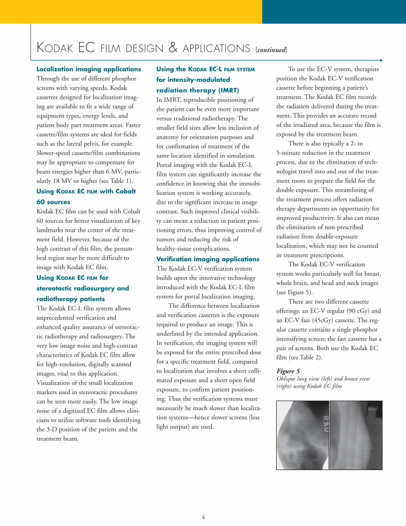
The Kodak EC-V verification system works particularly well for breast,whole brain, and head and neck images(see Figure 5).
There are two different cassetteofferings: an EC-V regular (90 cGy) andan EC-V fast (45cGy) cassette. The reg-ular cassette contains a single phosphorintensifying screen; the fast cassette has apair of screens. Both use the Kodak ECfilm (see Table 2).
Figure 5Oblique lung view (left) and breast view(right) using Kodak EC film
5
Benefits realized from using
KODAK EC FILM
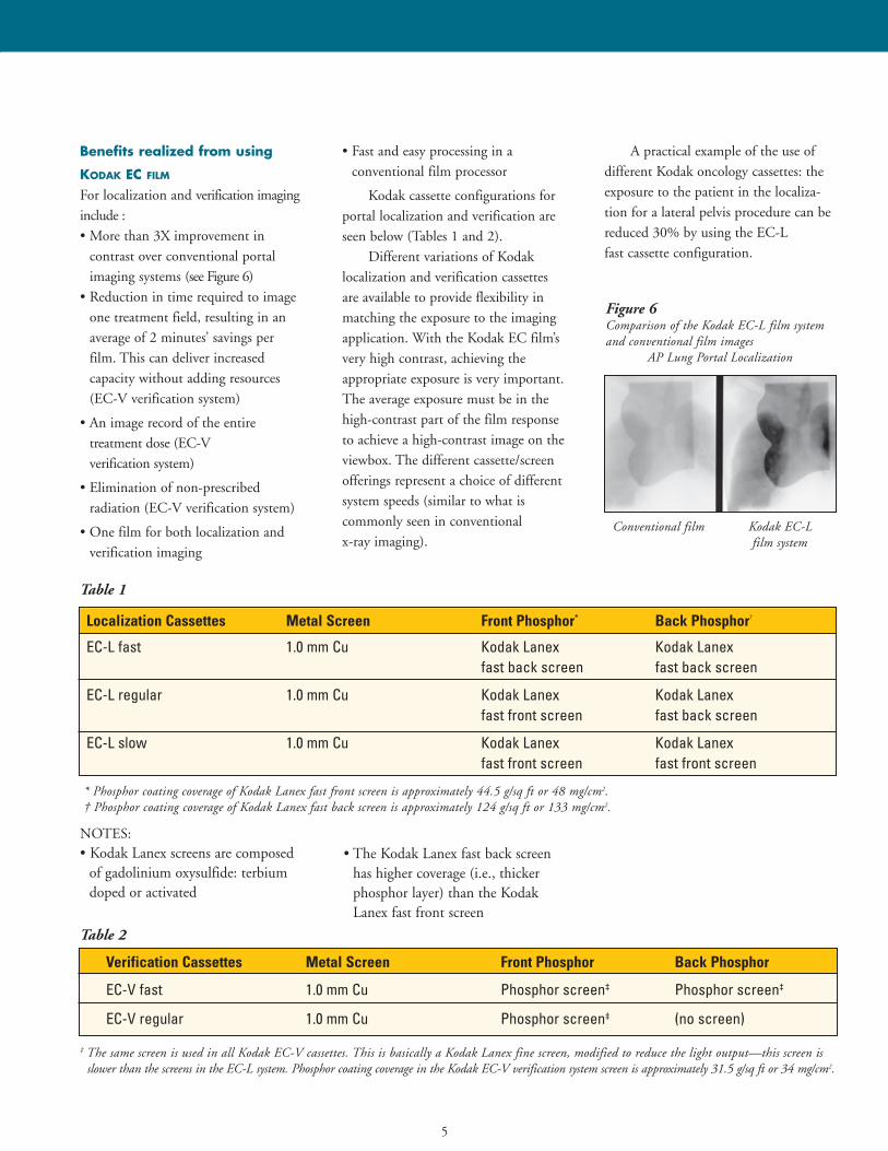
For localization and verification imaginginclude :• More than 3X improvement in
contrast over conventional portalimaging systems (see Figure 6)
• Reduction in time required to imageone treatment field, resulting in anaverage of 2 minutes’ savings per film. This can deliver increased capacity without adding resources (EC-V verification system)
• An image record of the entire treatment dose (EC-V verification system)
• Elimination of non-prescribed radiation (EC-V verification system)
• One film for both localization and verification imaging
• Fast and easy processing in a conventional film processor
Kodak cassette configurations forportal localization and verification areseen below (Tables 1 and 2).
Different variations of Kodak localization and verification cassettes are available to provide flexibility inmatching the exposure to the imagingapplication. With the Kodak EC film’svery high contrast, achieving the appropriate exposure is very important.The average exposure must be in thehigh-contrast part of the film responseto achieve a high-contrast image on theviewbox. The different cassette/screenofferings represent a choice of differentsystem speeds (similar to what is commonly seen in conventional x-ray imaging).
A practical example of the use of different Kodak oncology cassettes: theexposure to the patient in the localiza-tion for a lateral pelvis procedure can bereduced 30% by using the EC-L fast cassette configuration.
Localization Cassettes Metal Screen Front Phosphor* Back Phosphor†
EC-L fast 1.0 mm Cu Kodak Lanex Kodak Lanexfast back screen fast back screen
EC-L regular 1.0 mm Cu Kodak Lanex Kodak Lanexfast front screen fast back screen
EC-L slow 1.0 mm Cu Kodak Lanex Kodak Lanexfast front screen fast front screen
Verification Cassettes Metal Screen Front Phosphor Back Phosphor
EC-V fast 1.0 mm Cu Phosphor screen‡ Phosphor screen‡
EC-V regular 1.0 mm Cu Phosphor screen‡ (no screen)
* Phosphor coating coverage of Kodak Lanex fast front screen is approximately 44.5 g/sq ft or 48 mg/cm2.† Phosphor coating coverage of Kodak Lanex fast back screen is approximately 124 g/sq ft or 133 mg/cm2.
‡ The same screen is used in all Kodak EC-V cassettes. This is basically a Kodak Lanex fine screen, modified to reduce the light output—this screen isslower than the screens in the EC-L system. Phosphor coating coverage in the Kodak EC-V verification system screen is approximately 31.5 g/sq ft or 34 mg/cm2.
Table 1
Table 2
NOTES:• Kodak Lanex screens are composed
of gadolinium oxysulfide: terbiumdoped or activated
• The Kodak Lanex fast back screenhas higher coverage (i.e., thicker phosphor layer) than the KodakLanex fast front screen
Figure 6Comparison of the Kodak EC-L film systemand conventional film images
AP Lung Portal Localization
Conventional film Kodak EC-L film system
6
PROCESSING KODAK EC FILM
The film-processing stage in the creation of the final image is criticallyimportant in diagnostic and therapeuticimaging. Inattention to processing con-ditions can reduce image quality.
The micro-cubic grain emulsiontechnology used in Kodak EC film pro-vides highly stable sensitometricresponse in varying processing environ-ments, which is very important with thisfilm’s uniquely high average gradient. Inaddition, it has excellent drying charac-teristics. It is best suited for processingin standard 90-second or equivalentcycles. For optimum results, Kodak rec-ommends the use of Kodak RP X-OmatDeveloper and Replenisher and KodakRP X-Omat LO Fixer and Replenisher.Kodak EC film can be handled under
safelight illumination. A Kodak GBX-2 safelight filter or equivalent isrecommended.
Replenishment rate suggestions forprocessing Kodak EC film are the sameas those rates recommended by Kodakfor processing most Kodak medical x-ray films for general radiography.Kodak service bulletin #30 gives detailedinformation on setting replenishmentrates for various films, film volumes, andKodak processor types. Note that forlower-volume-processing circumstances,higher replenishment rates are recom-mended. Often the daily film processingvolume in an oncology imaging depart-ment may suggest setting higher replen-ishment rates. The CAT No. for this service bulletin is 835 7923. It is also
cross-referenced by a Kodak part#632661 or Kodak publication numberN-923. There is no charge for this service bulletin.
The automated Health Imaging faxback system can also be accessed 24hours a day to send this document tothe receiver’s fax machine. The USAtoll-free number is 1-800-336-4722 andthe 6-page service bulletin #30 is docu-ment #800210. The Kodak fax back sys-tem can also be accessed by dialing USAarea code (716) 781-8473. A touch-tonephone is required to use this system.
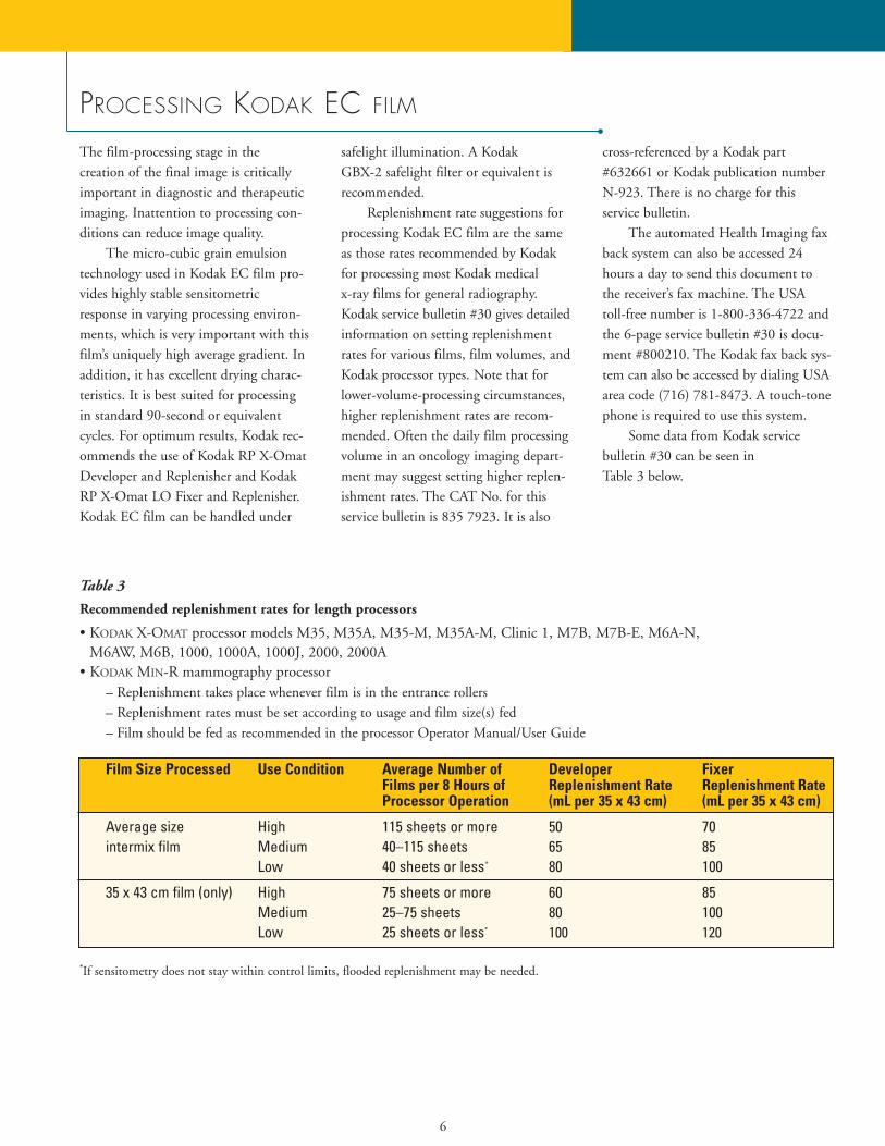
Some data from Kodak service bulletin #30 can be seen in Table 3 below.
Film Size Processed Use Condition Average Number of Developer FixerFilms per 8 Hours of Replenishment Rate Replenishment RateProcessor Operation (mL per 35 x 43 cm) (mL per 35 x 43 cm)
Average size High 115 sheets or more 50 70intermix film Medium 40–115 sheets 65 85
Low 40 sheets or less* 80 100
35 x 43 cm film (only) High 75 sheets or more 60 85Medium 25–75 sheets 80 100Low 25 sheets or less* 100 120
Table 3
Recommended replenishment rates for length processors
• KODAK X-OMAT processor models M35, M35A, M35-M, M35A-M, Clinic 1, M7B, M7B-E, M6A-N,M6AW, M6B, 1000, 1000A, 1000J, 2000, 2000A
• KODAK MIN-R mammography processor– Replenishment takes place whenever film is in the entrance rollers– Replenishment rates must be set according to usage and film size(s) fed– Film should be fed as recommended in the processor Operator Manual/User Guide
*If sensitometry does not stay within control limits, flooded replenishment may be needed.
7
“Chemistry matters”Different types of films respond differently in different types of process-ing chemicals. This variation can occuramong different processing chemistrytypes from the same manufacturer, orfrom manufacturer to manufacturer. Insome cases, just switching to the chem-istry made and recommended by thefilm manufacturer can yield visiblechanges on the viewbox. In other words,there can be a difference between“changing chemistry” from old solutionsto fresh solutions and “changing chemistry” from one type or brand to another.
Positively affected aspects caninclude increased speed (i.e., reducedmonitor units), improved image contrast, possible reduction in dryer artifacts, and “cooler” image tone. Withthe knowledge that portal imaging bynature does not offer an abundance ofimage contrast, it makes sense to reviewthe film manufacturer’s recommenda-tions for processing chemistry.
The special sensitometric character-istics and performance of Kodak ECfilm are optimized when proper atten-tion is given to processing conditions.Many common problems with imagequality stem from the processing envi-ronment. The typical sources for manyof these imaging concerns include insufficient chemistry replenishment,chemistry type and condition, processortype and condition, and safelighting.
Poor processing conditions canundermine the best efforts of the radia-tion therapist in exposure selection, and possibly result in higher exposures thannecessary. Inconsistent film densities overtime can be another consequence of a lesswell-controlled processing environment.
The film processorThe general condition of the film processor and/or the type of film proces-sor can influence the performance ofKodak EC film as well. As a group, theso-called “shallow tank” or “tabletop”film processors have internal roller pathand “roller strike” designs which neces-sarily differ in many aspects from thoseseen in larger processors. These designdifferences tend to produce more pro-cessing artifacts on Kodak EC film.There can also be differences in chemi-cal oxidation rates among these smallprocessors. Smaller internal tank vol-umes can sometimes mean that smalleramounts of chemistry contaminationand replenishment irregularities will pro-duce visible density differences in films.For these reasons, processing Kodak ECfilm in “shallow-tank” automatic filmprocessors is not encouraged.
In some situations and environ-ments with shallow tank-type processors (and with larger film processors too), it is useful to set the recommendedprocessor up for what is called “floodedreplenishment.” Flooded replenishmentis typically recommended for low-vol-ume processing conditions. In such conditions, there is a greater chance ofchemical oxidation and resultingimpaired image quality/consistency overtime. Flooded replenishment is a prac-tice where chemistry replenishment isdelivered regularly via a timer mecha-nism, whether or not film is beingprocessed. In conjunction with this,there is usually a change to the normalroutine of adding “starter” solution tothe developer tank inside the processorupon a chemistry change. With floodedreplenishment, the addition of startersolution is omitted, so both the internal
processor tank and the external replenisher tank contain the same iden-tically prepared developer. Many filmprocessors today have built-in electronicsto allow quick setup for flooded replenishment if this is needed.
There is additional discussion on selected “processing” topics in this guidein the “Questions and Answers” section.
Safelight recommendationsIt is wise to check safelight perfor-mance/integrity semi-annually, or asneeded. Small cracks can develop in thefilter material over time, allowing whitelight to strike the film, and this cancause intermittent, irregular artifactsthat are sometimes hard to trace. Usethe right type of safelight filter alongwith the proper type and wattage lightbulb. Kodak recommends the KodakGBX-2 safelight filter or equivalent forKodak EC film. Maximum bulb wattageshould be 15 watts for direct illumina-tion and 25 watts for indirect illumina-tion. If direct illumination is used, thesafelight(s) should be at least 4 feet(1.22 meters) from the film-handling area(s).
Even the way a safelight filter isinstalled in the fixture, i.e., its orienta-tion front vs. back, may be specificallyindicated. With the Kodak GBX-2 safelight filter, the filter should be oriented so that a person looking at theinstalled filter can read the lettering onthe filter glass.
PROCESSING KODAK EC FILM (continued)
You can also perform the following“quick” test if the Kodak safelight testkit is not available:1. Place a loaded cassette on top of the
treatment table and expose a 35 x 43-cm field to 2 MU for Kodak EC film.Turn off all lights and safelights in darkroom.
2. Remove the film and cover half the exposed film area with an opaquecover (film box, film box stiffenerboard, etc.)
3. Turn on safelight(s) and allow theuncovered half to remain exposed tothe safelight for 2 minutes.
4. Turn off safelight(s) and process the film.
5. Using a densitometer make two optical density readings near the middle of the film; one on the covered and one on the uncovered side.
6. The optical density of the uncoveredhalf of the film should be between 1.0and 1.4. Consider adjusting the exposure if the optical density is notin this range.
7. If there are differences in optical den-sity greater than 0.05, safelightintegrity, bulb wattage, or safelightlocation(s) should be checked.
To check for white-light leaks in thedarkroom, it is useful to go into thedarkroom, turn ALL lighting off, andremain in the darkroom for several min-utes to allow vision to adjust. (Lights onenergized processors or other darkroomdevices are typically OK.) Small white-light leaks around doors or aroundcutouts in walls for processors are easierto detect after the eyes have some timeto adjust to total darkness. Rememberthat not all light leaks might be seenfrom an upright, standing height, somove around in the darkroom andexamine the darkroom from differentangles and heights.
Film storage and handling
recommendationsIdeally, all packages of film should bestored in an area properly shielded frompenetrating radiation at a temperature of50 to 70 degrees F (10 to 21 degrees C).Store opened packages at 30% to 50%relative humidity. Store processed imagesat 60 to 80 degrees F (15.5 to 26.5degrees C) and 30% to 50% relative humidity.
Each package of film should beplaced on edge to avoid pressure mark-ing the film. Use older dated film first.Handle film carefully to avoid physicalstrains caused by pressure, creasing,buckling, and friction. Film should notbe drawn rapidly from the box or thecassette, or be handled in any way thatwould cause static electricity discharges.
8
9
SCREEN CLEANING AND ANTISTATIC TREATMENT
The phosphor screens in Kodak film system cassettes can be cleaned usingKodak intensifying screen cleaner andantistatic solution. Here are the Kodak-recommended screen-cleaning and antistatic application instructions:
Cleaning intensifying screens:1. Dampen a clean, lint-free gauze pad
or sponge with the solution. Use theminimum amount of screen cleanerneeded to moisten the cotton ball orgauze. Excess screen cleaner will notimprove screen cleanliness, nor willthis facilitate rapid air-drying of the screen(s).
2. Wipe one screen at a time. Aftercleaning, wipe each screen again with a dry, clean, lint-free gauze pador sponge.
3. Allow screens to air dry completelybefore returning them to service.
Antistatic treatment (if this is neces-sary or desired):1. Clean screen(s) as
recommended above.2. Apply a second application of
the solution to the screen(s) with a clean, lint-free gauze pad. DO NOT WIPE THE SCREEN(S)DRY. Set the screen(s) aside untilthoroughly dry.
3. When dry, return cassette and screensto service.
If Kodak intensifying screen cleanerand antistatic solution is not available, amild soap-and-water solution may beused following the procedure given insteps 1 through 3 in the screen cleaninginstructions in this section. Do not usesoaps or detergents containing brighten-ing agents. Denatured ethyl alcohol mayalso be used, but only in small amountsand confined to the screen surface.Avoid excessive pressure and rubbingthat may damage the screen surface.
The use of any cleaning agentsother than those specifically suggestedfor cleaning Kodak intensifying screensis not recommended.
COMPATIBILITY OF EC FILMS WITH SELECT KODAK PRODUCTS
Kodak EC film and EC-V verificationsystem cassettes use the Kodak X-Omatand X-Omatic cassettes that are fullycompatible with Kodak multiloaderunits models XML 7000, ML 700 plus,XML 300 plus, and XML 300.
The Kodak multiloader ML 700 utilizes infrared film sensors that may not reliably detect the almost transparent Kodak EC film at somepoints during film transport within thisparticular model.
Kodak EC film can be used withthe Kodak x-ray film identificationprinter, model B. The X-Omatic identification camera, model 2, can bemodified to be compatible with
Kodak EC film. This modification willprovide the ability to record patientinformation on both EC and conven-tional films. Contact your regionalKodak oncology manager to receive further information on this modificationpackage. These units are operated in full roomlight.
The Kodak x-ray film identificationprinter, model B, can also be used forexposing patient identification on thisand all film. This is a small, darkroom-operated device that can be orderedthrough your dealer. Designed for use ina darkroom setting, the model B printer is a cost-effective solution todata-recording needs.
A longer exposure is necessary torecord patient information on KodakEC film with the model B printer,necessitating a slightly different opera-tion of the printer in practice. Themodel B printer is also compatible withKodak simulation film and most othergeneral-purpose x-ray films.
TECHNICAL CONSIDERATIONS AND
TECHNIQUE RECOMMENDATIONS FOR EC-L FILM SYSTEM
Technical considerations for
EC-L film systemKodak EC film and Kodak EC-L cassettes have been specifically designedto produce high-contrast images at themegavoltage energies of therapy radia-tion. The high contrast enables greatervisualization of anatomical structures,which can help in ensuring the appro-priate placement of the treatment beamin a portal localization procedure.
With high contrast, the latitude ofthe film is reduced. This puts greateremphasis on careful control of the exposure conditions to create a consis-tent image. The consistent productionof high-quality EC-L images requirescareful consideration of all the factorsaffecting exposure.
An estimation of the amount of radiation to expose the Kodak ECfilm/EC-L cassette is based on the following factors:• Energy of the radiation beam• Geometry • Patient thickness or separation• Field size• Film processing
Following a few simple steps willensure optimal EC-L system images, andlead to greater confidence in therapylocalization. At the end of a brief discussion on the factors listed above,technique charts that can be developedand used to estimate the exposure for
Kodak EC film and EC-L cassettes are presented.
In these charts, a double exposure isspecified in the form of x+y. The firstnumber refers to the exposure to thetreatment field and the second numberto the exposure to the secondary or openfield. Note that in these tables, only 1 MU is typically specified to the treat-ment field. The rationale is that thisminimizes the difference between thetreatment exposure relative to the totalexposure and works to ensure that thetreatment field is not too dark relative tothe secondary or open field.
If it is necessary to manipulate the exposures specified in these charts,always add or subtract exposure fromthe secondary or open field. Additionalexposure to the treatment field shouldbe considered only in situations wherevery large exposures are necessary.
Using multiple energiesMany modern treatment machines canoperate at multiple energies. The lowestenergy available should be used for portfilming, because the contrast betweenstructures (i.e., the subject contrast) willbe greatest at lower energies. This willresult in better visualization of structuresin the image. When high energies areused, in addition to lower contrast, thereis greater transmission through thepatient, and more energy reaching thereceptor. As a result, less exposure is
required. The techniques included at theend of this discussion have been separat-ed according to the energy of the radia-tion beam. Note that less total exposureis required at higher treatment energies.
Image geometryGeometry is an important considerationin determining the exposure for anyradiographic procedure. Factors influ-encing geometry of the source relative to the patient and the film(image receptor) are the location of the disease, the orientation of the beam,and the access around the patient.
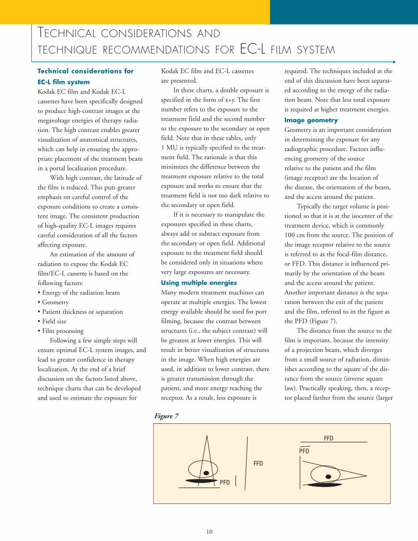
Typically the target volume is posi-tioned so that it is at the isocenter of thetreatment device, which is commonly100 cm from the source. The position ofthe image receptor relative to the sourceis referred to as the focal-film distance,or FFD. This distance is influenced pri-marily by the orientation of the beamand the access around the patient.Another important distance is the sepa-ration between the exit of the patientand the film, referred to in the figure asthe PFD (Figure 7).
The distance from the source to thefilm is important, because the intensityof a projection beam, which divergesfrom a small source of radiation, dimin-ishes according to the square of the dis-tance from the source (inverse squarelaw). Practically speaking, then, a recep-tor placed farther from the source (larger
10
Figure 7
11
FFD) will require the specification of ahigher exposure technique in order toachieve adequate darkening of the film.
If the radiation originating at thesource of the treatment machine werethe only radiation, then the FFD wouldbe the only important geometric consid-eration impacting technique. However,the intensity of radiation behind thepatient has been observed to fall offmore rapidly than would be predictedby the inverse square of the FFD. Adependence that is roughly related to theinverse cube of the FFD has been mea-sured empirically. This dependence isunderstood in terms of two additionalfactors: electrons originating from inter-actions within the patient, and the prox-imity of this patient source of radiationto the image receptor.
At megavoltage energies, photonsthat interact within the patient produceelectrons. Some of the electrons createdclose to the exit of the patient canescape into the gap between the patientand the image receptor. Some of thesewill reach the receptor and interact toexpose the film. These electrons effec-tively act as a second source of radiation.There is a greater impact associated withthe receptor placement relative to theradiation from the patient than the ther-apy source, due to the fractional dis-tances involved. The prediction, whichhas been verified empirically, is that theoptical density falls (due to the drop inintensity) much faster than would bepredicted by the inverse square of theFFD alone.
Understanding the implications ofthe distance between the patient and thereceptor (PFD) is extremely importantin ensuring consistent results with thehigh contrast and narrow latitude of
EC-L exposures. For optimal imagequality, the distance between patient andcassette should be reduced as much as isreasonably possible. As the distancebetween patient and cassette increases,density decreases, following the inversesquare law. Kodak EC film will amplifythis effect due to its considerably higherfilm contrast vs. conventional films. Ifdistance increases, a compensatingincrease in monitor units will need to be made.
This should be remembered if andwhen the cassette is placed at differentdistances from the patient each time thepatient is treated. Changes in densitydue to the contrast characteristics of theKodak EC film should be anticipated,and proper exposure techniques for eachsituation should be noted. The distancebetween the patient and the film is moreimportant than the distance between thesource and the film for predicting theappropriate exposure technique.
How is geometry reflected in thespecification of the technique charts? Inthe AP projection, where the imagereceptor is placed beneath the patient,the cassette is commonly rested on sup-ports beneath the patient couch. This isvery desirable, as the cassette is placed ata fixed and reproducible distance relativeto the source and the patient.
In other projections, the beam maytraverse a greater distance across thepatient, and the patient couch may pre-vent getting the image receptor close tothe patient. In this case, much greaterdistances would be involved and expo-sures would be expected to increase.This is reflected in both the geometryand the recommended exposures speci-fied in the technique charts for AP vs.lateral procedures. The increase in the
exposures for the lateral geometry is dueto both the increases in radiation fromthe source (FFD) and radiation from thepatient (PFD).
The charts provided in this sectionare for use with the geometry specified.Other geometries are possible; however,it will be necessary to customize thetechniques accordingly. The discussionabove should be used as a guide: payclose attention to the PFD. Using asmaller PFD will minimize the exposurerequired. As PFD increases, an increasein exposure will be required (i.e., addexposure to the open field of 1 MU foreach additional foot of PFD).
It is very important to note thatonce a geometry is chosen, the reliableproduction of consistent high-qualityEC film images requires careful atten-tion to and consistent use of that geometry. Many facilities have improvedtheir consistency by using a short ruleror piece of string to ensure a consistentseparation between the patient and the film.
Patient thicknessThe thickness of the patient will affectthe amount of radiation reaching theimage receptor. As patient thicknessincreases, more exposure is needed tocompensate for the increased attenua-tion. This is reflected in the techniquecharts in this guide, in that the tech-niques for some anatomical parts havebeen divided according to patient pro-file: small, medium, and large. Note thatexposure has been added to the openfield as the patient thickness increases.In situations where the patient is eithervery thick or very thin, consider addingor subtracting exposure from the secondary or open field.
12
T E C H N I C A L C O N S I D E R A T I O N S A N D T E C H N I Q U E
R E C O M M E N D A T I O N S FOR EC-L FILM SYSTEM (continued)
Field sizeThe field size is not specified in thetechnique charts. It is important to notethat field size can affect the techniqueselection, because the amount of scat-tered radiation will increase as field sizeincreases. This will cause the overall density of the image to increase. If largefields are being used, then the exposureshould be reduced in the secondary oropen field.
This relationship between field sizeand image density is more apparent withimaging systems that use intensifyingscreens, such as the Kodak EC-L filmsystem, coupled with the approximately3X contrast amplification delivered byKodak EC film. Small adjustments orchanges in radiation intensity are translated into more pronounced imagedensity changes, due to the combinationof intensifying screens and the very-high-contrast film.
This same principle operates to a lesser extent among the typical choicesof low-contrast, medium-contrast, and
high-contrast general radiographic filmsin conventional medical radiography.The very-high-contrast films currentlyused in film-screen mammographyimaging also place similar demands onthe accuracy of exposure parameters,attention to body part thickness, fieldsize, and collimation.
The size of the treatment field willbe determined in the treatment plan.Some additional consideration should begiven to the size of the secondary oropen field. Using a large secondary fieldin the hopes of seeing more anatomicallandmarks will increase the scatter, andreduce the contrast of the image. Thesecondary or open field should bedefined according to a fixed incrementfrom the dimensions of the treatmentfield, rather than using a very large field,or one corresponding to the maximumopening of the port. A 5-cm incrementis recommended to allow increased visualization of the regional anatomy,without excessive increase in the amountof scattered radiation.
Film processingProper film processing is important withany medical imaging film. Processingconditions can change exposures by asmuch as 50 to 100%. The techniquecharts listed on the following pagesassume that Kodak recommendationsfor processing of EC film are being followed. These recommendations aresummarized in Kodak service bulletin#30. Local processing conditions caninfluence the speed and contrast. Ifspeed is affected (the images are dark orlight), manipulate (reduce or increaseexposure) the exposure recommendedfor the secondary or open field toachieve the desired appearance.
13
KODAK EC-L FILM SYSTEM TECHNIQUE CHARTS
• Using the charts1. First, identify the energy for which
filming will be performed (remember,the lowest energy available will produce the best results).
2. Pay particular attention to the distancebetween patient and film. If this distance needs to be increased due tothe access of the cassette and holderaround the patient, then it will be necessary to add exposure to the secondary or open field. If different distances are used, then the techniquesmay have to be adjusted.
3. Next, refer to the anatomical area to beimaged. The technique indicated isbased on standard considerations forthickness and field size. If the patientthickness differs from a standard thickness, add or subtract exposurefrom the open field accordingly. Forparticularly large treatment fields,decrease the exposure in the open fieldto account for increased scatter.
• Customizing the charts1. The charts are presented here as a
guide. The previous discussion in this section describes how geometryand the local processing conditions canimpact the exposure required forKodak EC film in Kodak EC-L cassettes. The exposures in the secondary or open field should bemodified to account for local preferences in these factors. Once atechnique is worked out, new chartsshould be produced, and careful attention to using those techniquesconsistently is recommended.
2. Unlike imaging at diagnostic energies, there is not a substantial difference in tissue attenuation atmegavoltage energies. For this reason,the biggest factors affecting the exposure required are not specificallydependent on the anatomy. Once theenergy and geometry have been deter-mined, patient thickness and field sizewould be the important factors. As analternative to the technique charts presented here which provide exposurerecommendations according to anatomy, a technique chart based onthickness and field size for a givengeometry and energy could be created.
• Fractional MUsThe charts provided express exposuresin integer increments (MUs). Integerincrements are common on mostmachines. Some manufacturers haveprovided for fractional increments ofexposure. If this is available, then techniques can be fine-tuned for evengreater optimization of exposure. Thepoints raised in this discussion can beused to guide the fine-tuning accord-ing to patient thickness, field size,geometry, and processing.
14
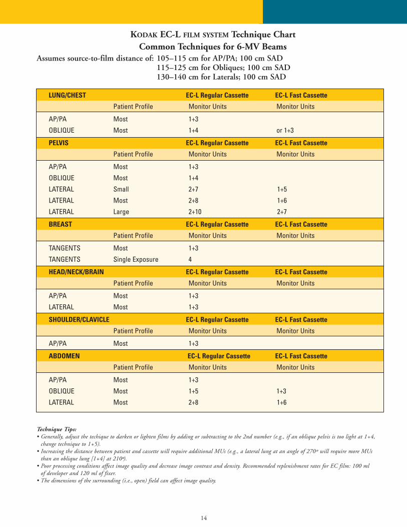
LUNG/CHEST EC-L Regular Cassette EC-L Fast Cassette
Patient Profile Monitor Units Monitor Units
AP/PA Most 1+3
OBLIQUE Most 1+4 or 1+3
PELVIS EC-L Regular Cassette EC-L Fast Cassette
Patient Profile Monitor Units Monitor Units
AP/PA Most 1+3
OBLIQUE Most 1+4
LATERAL Small 2+7 1+5
LATERAL Most 2+8 1+6
LATERAL Large 2+10 2+7
BREAST EC-L Regular Cassette EC-L Fast Cassette
Patient Profile Monitor Units Monitor Units
TANGENTS Most 1+3
TANGENTS Single Exposure 4
HEAD/NECK/BRAIN EC-L Regular Cassette EC-L Fast Cassette
Patient Profile Monitor Units Monitor Units
AP/PA Most 1+3
LATERAL Most 1+3
SHOULDER/CLAVICLE EC-L Regular Cassette EC-L Fast Cassette
Patient Profile Monitor Units Monitor Units
AP/PA Most 1+3
ABDOMEN EC-L Regular Cassette EC-L Fast Cassette
Patient Profile Monitor Units Monitor Units
AP/PA Most 1+3
OBLIQUE Most 1+5 1+3
LATERAL Most 2+8 1+6
Technique Tips:• Generally, adjust the techique to darken or lighten films by adding or subtracting to the 2nd number (e.g., if an oblique pelvis is too light at 1+4,
change technique to 1+5).• Increasing the distance between patient and cassette will require additional MUs (e.g., a lateral lung at an angle of 270º will require more MUs
than an oblique lung [1+4] at 210º).• Poor processing conditions affect image quality and decrease image contrast and density. Recommended replenishment rates for EC film: 100 ml
of developer and 120 ml of fixer.• The dimensions of the surrounding (i.e., open) field can affect image quality.
KODAK EC-L FILM SYSTEM Technique ChartCommon Techniques for 6-MV Beams
Assumes source-to-film distance of: 105–115 cm for AP/PA; 100 cm SAD115–125 cm for Obliques; 100 cm SAD130–140 cm for Laterals; 100 cm SAD
15
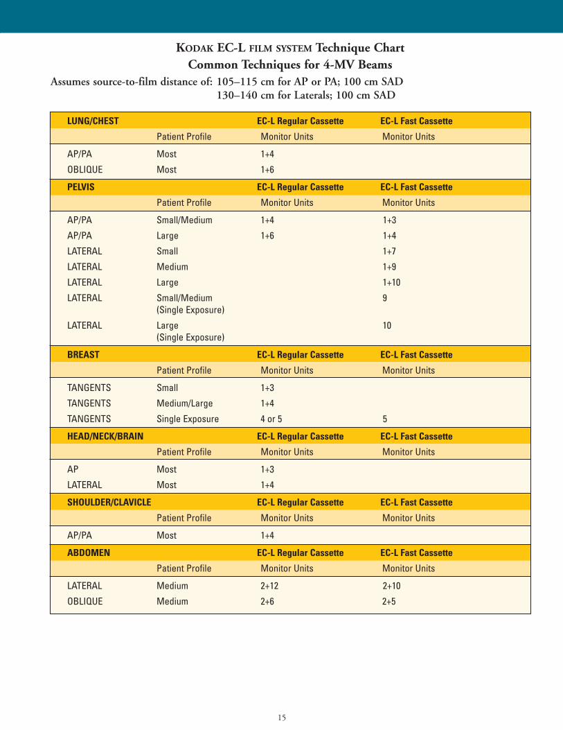
KODAK EC-L FILM SYSTEM Technique ChartCommon Techniques for 4-MV Beams
Assumes source-to-film distance of: 105–115 cm for AP or PA; 100 cm SAD130–140 cm for Laterals; 100 cm SAD
LUNG/CHEST EC-L Regular Cassette EC-L Fast Cassette
Patient Profile Monitor Units Monitor Units
AP/PA Most 1+4
OBLIQUE Most 1+6
PELVIS EC-L Regular Cassette EC-L Fast Cassette
Patient Profile Monitor Units Monitor Units
AP/PA Small/Medium 1+4 1+3
AP/PA Large 1+6 1+4
LATERAL Small 1+7
LATERAL Medium 1+9
LATERAL Large 1+10
LATERAL Small/Medium 9(Single Exposure)
LATERAL Large 10(Single Exposure)
BREAST EC-L Regular Cassette EC-L Fast Cassette
Patient Profile Monitor Units Monitor Units
TANGENTS Small 1+3
TANGENTS Medium/Large 1+4
TANGENTS Single Exposure 4 or 5 5
HEAD/NECK/BRAIN EC-L Regular Cassette EC-L Fast Cassette
Patient Profile Monitor Units Monitor Units
AP Most 1+3
LATERAL Most 1+4
SHOULDER/CLAVICLE EC-L Regular Cassette EC-L Fast Cassette
Patient Profile Monitor Units Monitor Units
AP/PA Most 1+4
ABDOMEN EC-L Regular Cassette EC-L Fast Cassette
Patient Profile Monitor Units Monitor Units
LATERAL Medium 2+12 2+10
OBLIQUE Medium 2+6 2+5
16
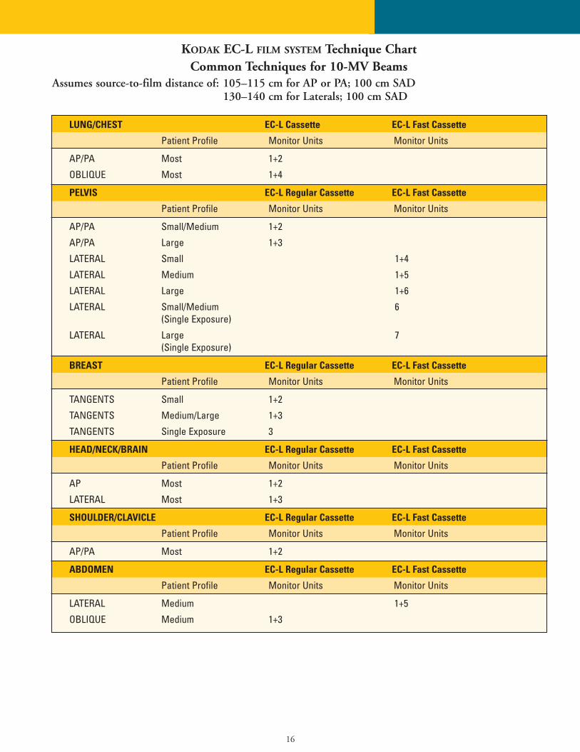
KODAK EC-L FILM SYSTEM Technique ChartCommon Techniques for 10-MV Beams
Assumes source-to-film distance of: 105–115 cm for AP or PA; 100 cm SAD130–140 cm for Laterals; 100 cm SAD
LUNG/CHEST EC-L Cassette EC-L Fast Cassette
Patient Profile Monitor Units Monitor Units
AP/PA Most 1+2
OBLIQUE Most 1+4
PELVIS EC-L Regular Cassette EC-L Fast Cassette
Patient Profile Monitor Units Monitor Units
AP/PA Small/Medium 1+2
AP/PA Large 1+3
LATERAL Small 1+4
LATERAL Medium 1+5
LATERAL Large 1+6
LATERAL Small/Medium 6(Single Exposure)
LATERAL Large 7(Single Exposure)
BREAST EC-L Regular Cassette EC-L Fast Cassette
Patient Profile Monitor Units Monitor Units
TANGENTS Small 1+2
TANGENTS Medium/Large 1+3
TANGENTS Single Exposure 3
HEAD/NECK/BRAIN EC-L Regular Cassette EC-L Fast Cassette
Patient Profile Monitor Units Monitor Units
AP Most 1+2
LATERAL Most 1+3
SHOULDER/CLAVICLE EC-L Regular Cassette EC-L Fast Cassette
Patient Profile Monitor Units Monitor Units
AP/PA Most 1+2
ABDOMEN EC-L Regular Cassette EC-L Fast Cassette
Patient Profile Monitor Units Monitor Units
LATERAL Medium 1+5
OBLIQUE Medium 1+3
17
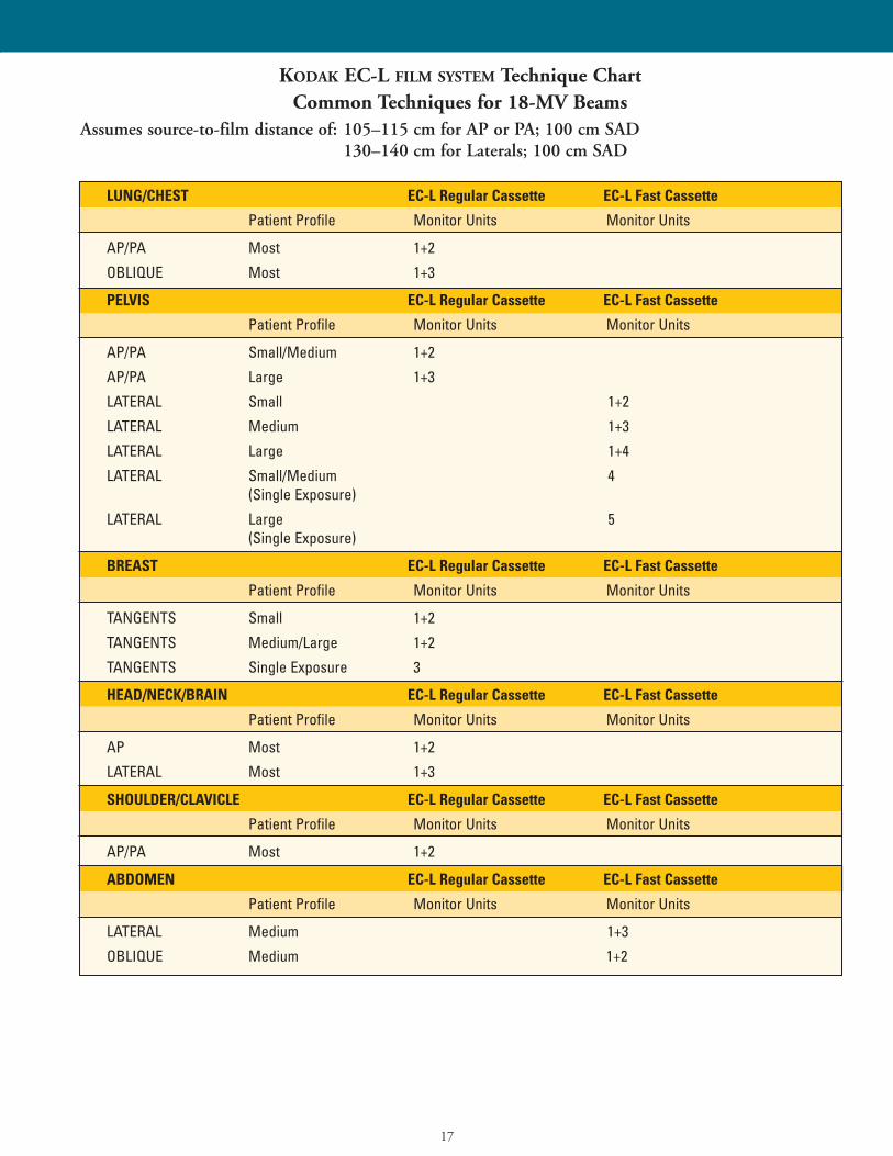
KODAK EC-L FILM SYSTEM Technique ChartCommon Techniques for 18-MV Beams
Assumes source-to-film distance of: 105–115 cm for AP or PA; 100 cm SAD130–140 cm for Laterals; 100 cm SAD
LUNG/CHEST EC-L Regular Cassette EC-L Fast Cassette
Patient Profile Monitor Units Monitor Units
AP/PA Most 1+2
OBLIQUE Most 1+3
PELVIS EC-L Regular Cassette EC-L Fast Cassette
Patient Profile Monitor Units Monitor Units
AP/PA Small/Medium 1+2
AP/PA Large 1+3
LATERAL Small 1+2
LATERAL Medium 1+3
LATERAL Large 1+4
LATERAL Small/Medium 4(Single Exposure)
LATERAL Large 5(Single Exposure)
BREAST EC-L Regular Cassette EC-L Fast Cassette
Patient Profile Monitor Units Monitor Units
TANGENTS Small 1+2
TANGENTS Medium/Large 1+2
TANGENTS Single Exposure 3
HEAD/NECK/BRAIN EC-L Regular Cassette EC-L Fast Cassette
Patient Profile Monitor Units Monitor Units
AP Most 1+2
LATERAL Most 1+3
SHOULDER/CLAVICLE EC-L Regular Cassette EC-L Fast Cassette
Patient Profile Monitor Units Monitor Units
AP/PA Most 1+2
ABDOMEN EC-L Regular Cassette EC-L Fast Cassette
Patient Profile Monitor Units Monitor Units
LATERAL Medium 1+3
OBLIQUE Medium 1+2
18
ARTIFACT ISOLATION FUNDAMENTALS
This section provides a brief review ofselected classes of artifacts, their causes,and corrective measures. Artifacts areunwanted defects on the processed film.Both the types of possible film artifactsand the possible sources of such artifactsare numerous. The sources for film artifacts are not limited to the filmprocessor. A more comprehensive, 72-page spiral-bound Kodak publication,Film Artifact Diagnostics Guide, is availablefor further study. This publication isCAT No. 132 7246. The cost is approximately $30.00 (US), and it canbe ordered through any dealer of Kodakhealth imaging products or by callingyour local Kodak office directly. Forexample, in the USA, the Kodak numberto call is 1-800-677-9933. This publication is a good “reference manual”to identify many different types of imageartifacts, learn their cause(s), and obtain corrective suggestions.
There is another 28-page Kodak publication, called Identifying andCorrecting Proccessing Artifacts, which discusses a dozen of the most commonprocessor-related film artifacts. The CATNo. for this publication is 192 8324.The cost is approximately $6.00 (US).
When trying to identify the cause(s) of film artifacts, there are some basicobservations that are important to note, including:
Characteristics of the film:• Note leading film edge entering the
processor and trailing film edge• Does the artifact go away when a
different size film or film from a different emulsion batch is tried?
Characteristics of the artifact(s):• Is the artifact plus-density (dark) or
minus-density (light)?• Where does it occur on the film in
relation to the direction of film travel(i.e., parallel to the direction of filmtravel or perpendicular?)
• Does the artifact repeat on the film? If so, what is the spacing between artifacts?
• Is the artifact seen using transmittedlight or reflected light?
• Does the artifact occur randomlyon the film? (e.g., static, surfacescratches, kink marks)
Generally, there are six
basic guidelines to follow
when evaluating
process-related artifacts:1. Artifacts that appear on the upper
emulsion surface of the film resultfrom the upper components in the processor.
2. Artifacts that appear on the loweremulsion surface result from thelower components in the processor.
3. Plus-density artifacts are most likelycaused by problems in the film development stage or by pressure onthe film after exposure. With somefilms, pressure exerted on the filmprior to exposure can also result inplus-density artifacts.
4. Minus-density artifacts are most likelycaused by problems with the fixer,with pressure on the film before exposure, and/or by dust and dirt in a cassette.
5. Generally, reflected light reveals wash-or dryer-created artifacts. Locatingand viewing these flaws in the surface quality of a film is usu-ally easier with reflected light vs.transmitted light. However, verysevere wash- or dryer-created artifactscan often be seen using transmittedlight as well.
6. Transmitted light generally revealsother types of artifacts than those dis-cussed in guidelines 1 to 5.
There may be similarities among film processors and perhaps processingchemistry in the same institution or across different diagnostic imaging departments.
Artifacts from other sources
can include:• Static marks• Shadow images• Kink marks• Bent corners
19
QUESTIONS AND ANSWERS
Selected product usage
recommendations
Can I use Kodak EC film in metal-
screened cassettes for portal localiza-
tion and/or verification imaging?
No. This combination is not recommended for patient imaging. Themain reason is the very slow film speedof Kodak EC film. This would make the system speed too slow for use with patients.
Can I use conventional medical
x-ray film(s) in Kodak EC-L or EC-V
film system cassettes?
No. This is not recommended, becausethe higher speed of most medical x-rayfilms would make the resulting combina-tion too fast for patient use. A fraction of1 MU might be required, and deliveringthis amount of exposure is typically difficult with most equipment.
With the availability of the Kodak
EC-L or EC-V film systems for
localization and verification imaging,
are Kodak therapy cassettes L and V
still available?
Yes. Those who decide to use conven-tional screen-type medical x-ray filmswith metal-screened cassettes will be ableto purchase these cassettes. Some recom-mended films for use with the Kodaktherapy cassette L and therapy cassette Vare Kodak PPL-2 or Kodak X-Omat Kfilm for the L cassette and Kodak X-Omat V film for the V cassette.
Replenishment rates, chemistry
selection, and processor selection
What are the recommended replenish-
ment rates with Kodak chemicals for
processing Kodak EC film?
Radiation oncology centers and process-ing environments tend to have relatively
low-volume film-processing demands.Each site or situation should be analyzedindividually to determine the optimalchemistry replenishment rates needed toproduce consistent, high-quality images.Kodak service bulletin #30 provides the latest film replenishment recommendations for a variety of filmsand conditions.
See Page 6 in this Guide for somereplenishment rate recommendations.For many sites, 100 mL of developerand 120 mL of fixer provide a goodstarting point for setting replenishment rates.
Does the brand and/or type chemistry
I use affect the image quality?
Yes; particularly with the developer solu-tion. There are many choices of x-rayfilm developer solutions on the markettoday, and the performance of each canyield visible differences on the viewbox.Image contrast is a particularly impor-tant aspect in oncology imaging. Selectyour developer brand and type carefullyso that the film interpreter’s ability tosee important clinical details andanatomical landmarks is not compromised.
Fixer solutions can also affect differ-ent films in different ways. Fixer brandand/or type can affect performance characteristics such as film drying.Physical characteristics such as susceptibility to certain film processorartifacts can change with different fixertypes. Even viewbox characteristics suchas image tone can be affected by differ-ent fixer formulations. These examplesillustrate that the selection of fixer solution should be made with the Kodakrecommendations in mind.
Some chemicals, in concentrateand/or in mixed form, exhibit betterchemical stability and sensitometric
consistency over time. These can beimportant performance characteristics toconsider in oncology film-processingareas, which might not always see highvolumes of films processed daily.
For optimal image quality, we rec-ommend the use of Kodak RP X-Omatdeveloper and replenisher and Kodak RP X-Omat LO fixer and replenisher.
Does the automatic film processor
I select affect image quality?
Yes, in at least a couple of ways. The film processor’s internal design andchemicals circulation systems provide agitation to the film’s surface.Proper agitation and “flexing” of thefilm as it transports through the processor is a very precise science. Thisemulsion flexing combines with chem-istry recirculation system design to provide specific benefits in a number ofareas. Not all film processors do thisequally. Some smaller automatic filmprocessors with “shallow-tank” designscan affect important performance para-meters, including contrast and speed. Inaddition, a film processor’s design in the“wet tanks” as well as in the film-dryingsection can cause artifacts or imaging“noise” that interfere with the visibilityof clinical information.
We recommend a number of Kodak X-Omat processors for optimalprocessing of the broad variety of Kodakfilms for oncology imaging, including:• Model 2000 RA • Models 5000 RA and 3000 RA• Models 480 RA and M6B• Models M7B and M35
20
QUESTIONS AND ANSWERS (continued)
Safelights
Can my safelight(s) affect
image quality?
Yes. With improper safelighting conditions or damaged safelights, youmay see increased image density, lowerimage contrast, increased gross fog lev-els, and possibly other image artifacts aswell. Reduction in image contrast is par-ticularly detrimental in oncology imag-ing, where the typically lower-contrast images may make it more difficult to recognize any image contrastloss due to the lack of safelight integrity.
When images are too lightLight images are typically the result ofprocessing and exposure.
ProcessingCheck the working chemistry inside theprocessor for possible oxidation. If oxidized solutions exist, replace withfresh chemistry. If chemical replenish-ment rates are insufficient for the filmtype, volume, and/or film mix,processed films can appear to have agreen tint. Certain types of processingchemicals can sometimes produce similar shifts in image tone with somefilms. Insufficient fixer strength and/orunder replenishment can also affect theimage tone of processed films, givingfilms a milky or greenish appearance. Inaddition, film drying can be adverselyaffected in such circumstances, and therecan be an increased propensity for filmartifacts due to insufficient emulsion“hardening” in the fixer stage.
It is not unusual to add 1 MU tothe larger field because the processingchemistry is not optimized. This can bemore obvious on the lesser-exposed pro-jections. In some cases, a change to freshchemistry can bring an immediatechange. In other cases, a change in
chemistry brand or type could bringabout similar improvements.
ExposureIf you are exposing two fields on onefilm and the treatment field is too light,then the secondary field should be toolight as well. Increasing the monitorunits on the secondary field also darkensthe treatment field. Adding one or twounits to the technique, using the chartsprovided in this publication, should beall that is required to account for differences in normal chemistry and film fluctuations.
If the exposure guidelines in thispublication do not provide satisfactoryresults, you should seek help from yourregional Kodak oncology manager. Donot add monitor units to the treatmentfield. This will only make the secondaryfield appear lighter. Single-field usersshould never require an increase of more than one or two MU from theexposure guidelines recommended inthis publication.
When images are too darkDark images are often the result of processing chemistry, safelight, and filmstorage technique.
Processing, chemistry,
and safelight(s)Chemistry, processing, and darkroom“basics” can be the cause or contributingfactors when images are determined tobe too dark. Potential causes caninclude:• Developer temperature higher
than recommended• Chemistry activity higher than
normal (improper mixing, “starter”solution omitted)
• Chemistry changes from fresh to “seasoned” conditioning process
• Improper safelight conditions—theaccompanying image density increase,image contrast decrease, and highergross fog may be less easily or quicklynoticed on many oncology localizationand verification images. This is becausethese images typically have lowerimage contrast overall. In addition,typical patient images may have areasof higher density where added densitymay not be perceived as readily.
Placement of loaded cassettes in
the treatment roomFilms exposed to scatter radiation eitherpre- or post-exposure will appear to bedarker and/or lower in overall contrast.Kodak EC-L and EC-V system cassetteshave intensifying screens that very efficiently convert the scatter radiationenergy to light. This light can add additional exposure to the film, givingthe processed image additional density.
Putting loaded cassettes aside in thetreatment room during a treatment isnot recommended. Besides the effects ofaltered image density and/or image contrast, other aspects, including potential time savings and convenience,can be negatively affected as well.Sometimes the apparent mystery of density differences in films on the samepatient, using the same exposure, can bequickly solved by proper film/cassette storage.
21
Geometric factors and
intermittent density variations
Does field size affect image density?
Yes. There is a direct relationshipbetween field size and image density.The underlying cause is scatter energy.The larger the field size, the more scatteris created. This invites added density tothe image, particularly with the knowledge of the high inherent contrast of Kodak EC film. The significant increase (over 3X) in imagereceptor contrast provided by the KodakEC-L film system “amplifies” exposuredifferences into more pronounced density differences.
The practice of enlarging the field size to facilitate visibility of anatomiclandmarks can introduce less desirableimage results, including variable densities and reduced image contrast.The significantly higher image contrastlevel of Kodak EC film should helpdecrease or even eliminate this behaviorin many instances, providing improvedimage quality.
What about intermittent density shifts
or density variations on films?
This can happen for multiple reasons,including:• Processing• Scatter radiation exposure• Loss of safelight integrity• Inconsistent cassette-to-
patient distanceLooking at inconsistent cassette-to-
patient distance more closely, we recognize that different distance positioning in reverse PA views, obliqueviews, and tangent views can producedensity variations that may not initiallybe thought of as traceable to this cause.Differences in image magnification oncomparison films should alert the filminterpreter to inconsistent geometry as a possible reason for image density variations.
22
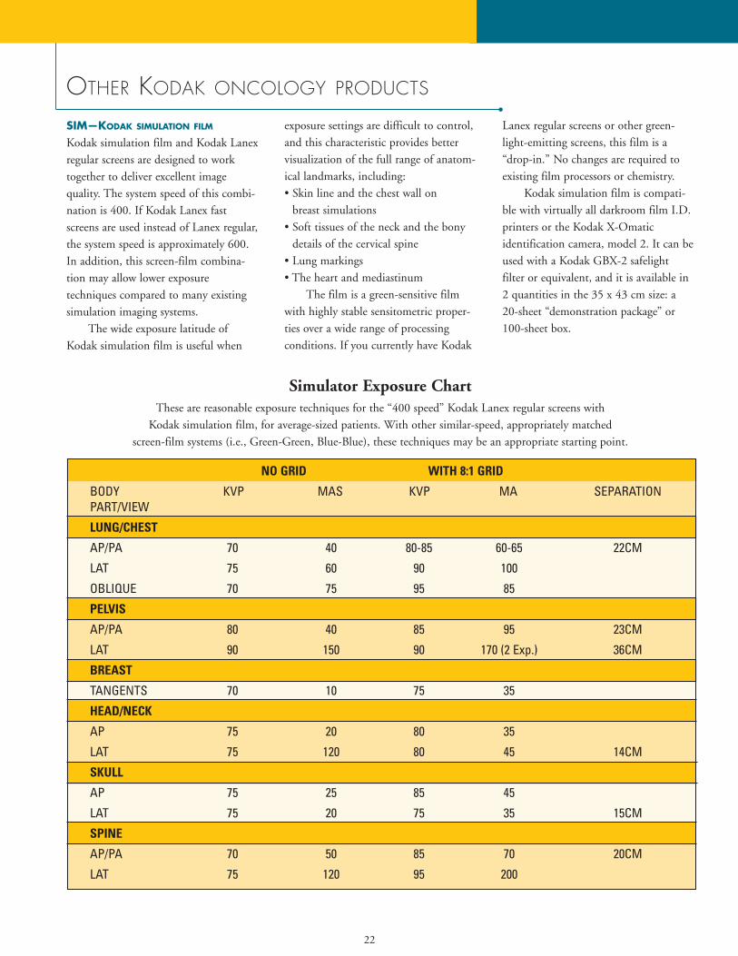
Simulator Exposure ChartThese are reasonable exposure techniques for the “400 speed” Kodak Lanex regular screens with
Kodak simulation film, for average-sized patients. With other similar-speed, appropriately matched screen-film systems (i.e., Green-Green, Blue-Blue), these techniques may be an appropriate starting point.
NO GRID WITH 8:1 GRID
BODY KVP MAS KVP MA SEPARATIONPART/VIEW
LUNG/CHEST
AP/PA 70 40 80-85 60-65 22CM
LAT 75 60 90 100
OBLIQUE 70 75 95 85
PELVIS
AP/PA 80 40 85 95 23CM
LAT 90 150 90 170 (2 Exp.) 36CM
BREAST
TANGENTS 70 10 75 35
HEAD/NECK
AP 75 20 80 35
LAT 75 120 80 45 14CM
SKULL
AP 75 25 85 45
LAT 75 20 75 35 15CM
SPINE
AP/PA 70 50 85 70 20CM
LAT 75 120 95 200
OTHER KODAK ONCOLOGY PRODUCTS
SIM—KODAK SIMULATION FILM
Kodak simulation film and Kodak Lanexregular screens are designed to worktogether to deliver excellent image quality. The system speed of this combi-nation is 400. If Kodak Lanex fastscreens are used instead of Lanex regular,the system speed is approximately 600.In addition, this screen-film combina-tion may allow lower exposure techniques compared to many existing simulation imaging systems.
The wide exposure latitude ofKodak simulation film is useful when
exposure settings are difficult to control,and this characteristic provides bettervisualization of the full range of anatom-ical landmarks, including:• Skin line and the chest wall on
breast simulations• Soft tissues of the neck and the bony
details of the cervical spine• Lung markings• The heart and mediastinum
The film is a green-sensitive filmwith highly stable sensitometric proper-ties over a wide range of processing conditions. If you currently have Kodak
Lanex regular screens or other green-light-emitting screens, this film is a“drop-in.” No changes are required toexisting film processors or chemistry.
Kodak simulation film is compati-ble with virtually all darkroom film I.D.printers or the Kodak X-Omatic identification camera, model 2. It can beused with a Kodak GBX-2 safelight filter or equivalent, and it is available in2 quantities in the 35 x 43 cm size: a20-sheet “demonstration package” or100-sheet box.
23
PPL-2—Portal pack
for localization (PPL)Kodak portal pack for localization isavailable in “Ready-Pack” packaging intwo sizes: 33 x 41 cm and 10 x 12 inches. The 33 x 41 cm film size allowsthe Ready-Pack envelope with film to fitneatly inside a 35 x 43 cm Kodak X-Omatic L radiation therapycassette. The Ready-Pack is a sealedenvelope containing film that can beused with or without a metal-screenedcassette. This packaging offers great con-venience in handling and can eliminatecarrying heavy cassettes from treatmentroom to darkroom and back.
CAT Nos. for PPL are 801 3963for the 33 x 41 cm size and 801 5059for the 10 x 12 in size.
KODAK X-OMAT RADIATION THERAPY
CASSETTES L and V and
KODAK X-OMAT VERIFICATION
FILM (XV)The Kodak X-Omat L radiationtherapy cassette contains a 1.0-mm-thickcopper-front screen and a 0.25-mm-thicklead-back screen. Its size is 35 x 43 cm.The 1.0-mm copper-front screen:• Prevents electrons generated within the
patient from reaching the film• Generates electrons, which are the pri-
mary source of film exposure. Becausethese electrons are much closer to thefilm emulsion than those generatedwithin the patient, image blur isreduced and resolution is improved
• Intensifies primary radiation to agreater extent than scattered photonsof lower energy, resulting in improvedsubject contrast
The 0.25-mm lead-back screen:• Serves as an intensifier that provides
additional exposure to the film due, inlarge part, to the back-scattering ofelectrons. This reduces the requirednumber of monitor units by a factor ofapproximately 2
Typically, conventional blue-sensi-tive medical x-ray films are used withthis cassette, as well as certain films inReady-Pack packaging and size to fitinside this cassette. Tests have shownthat there is minimal resolution losswhen film is exposed in a ready pack asopposed to direct contact film-(metal)screen exposure.
A slightly different cassette designedfor verification imaging is the Kodak X-Omat V radiation therapy cassette. Its size is 35 x 43 cm. This cassette has the same 1.0-mm copper-frontscreen as the Kodak X-Omat L radiationtherapy cassette, but instead of the lead-back screen it has a lightweight 0.4-mmthermoplastic polymer back screen. Thissystem is paired with Kodak X-Omat Vfilm packaged in Ready-Pack format, aslow film capable of recording exit doses resulting from many radiation treatments.
KODAK EDR-2 FILM for dosimetry/
QA/equipment calibrationEDR-2 film is a new addition to the Kodak Ready-Pack product family.Kodak now offers EDR-2 film as well asPPL and XV in Ready-Pack format.
EDR-2 film is a convenient means for calibration and monitoring of exposures.• Two sizes available: 35 x 43 cm and
10 x 12 inches• Widely available through distributors
of Kodak medical imaging products• Excellent for relative dosimetry (e.g.,
field uniformity, equipment characterization: field shapes, portopenings, MLCs)
• With appropriate calibration, film maybe applicable to absolute dosimetry(e.g., high-dose treatment strategiessuch as IMRT)
EDR-2 is intended for direct expo-sure applications only. Its featuresinclude:• Wide response range• Approximately linear (see graph)• Robust processing• Available in convenient
Ready-Pack format
Dose response evaluationExact dose responses depend on processing conditions (processing time,processing temperature, processingequipment, processing chemistry); thedensity sampling (digitizer equipmentand calibration) and exposure monitor-ing equipment. The exact response relationship should be measured andverified for the local conditions.
24
Measurement techniqueThe dose response of a film should bemeasured using appropriate amounts ofbuildup and backscatter material, with arange of field sizes and energies. Thefilms should be processed using the conditions given in Kodak’s service bulletin #30.
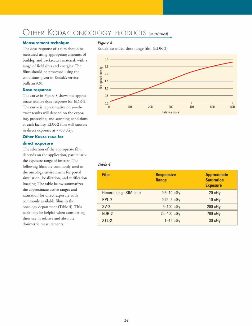
Dose responseThe curve in Figure 8 shows the approx-imate relative dose response for EDR-2.The curve is representative only—theexact results will depend on the expos-ing, processing, and scanning conditionsat each facility. EDR-2 film will saturatein direct exposure at ~700 cGy.
Other KODAK FILMS for
direct exposureThe selection of the appropriate filmdepends on the application, particularlythe exposure range of interest. The following films are commonly used inthe oncology environment for portalsimulation, localization, and verificationimaging. The table below summarizesthe approximate active ranges and saturation for direct exposure with commonly available films in the oncology department (Table 4). Thistable may be helpful when consideringtheir use in relative and absolute dosimetric measurements.
OTHER KODAK ONCOLOGY PRODUCTS (continued)
Film Responsive Approximate Range Saturation
Exposure
General (e.g., SIM film) 0.5–10 cGy 20 cGy
PPL-2 0.25–5 cGy 10 cGy
XV-2 5–100 cGy 200 cGy
EDR-2 25–400 cGy 700 cGy
XTL-2 1–15 cGy 30 cGy
Table 4
Figure 8 Kodak extended dose range film (EDR-2)
25
OTHER KODAK PRODUCTS
Film processors• Kodak X-Omat 2000 processor
The Kodak X-Omat 2000 and2000A processors offer the proven relia-bility of Kodak M35 and M35A proces-sors plus rapid-cycle processing capabili-ty, to deliver 34% higher throughput for medium- to low-volume processingneeds. Key features include:
– Automatic standby control– Ambient temperature wash water– Developer temperature control to
+/– 0.5 degrees F (+/– 0.3 degrees C)
– 220-volt or 110-volt models;either can be installed forthrough-the-wall operation usingan installation kit provided withthe processor
– Designed to minimize servicetime through ease of installation,ready service access, and readilyavailable Kodak M35/M35Aprocessor parts
– Can process up to 100 35 x 43-cm sheets of film/hour instandard cycle (120 sec. leadingedge in/out)
– Can process up to 125 35 x 43-cm sheets of film/hour in rapidcycle (90 sec. leading edge in/out)
• Kodak X-Omat 3000 RA processorThe Kodak 3000 RA processor is
designed for medium-volume film processing needs. It can process up to150 35 x 43-cm sheets of film per hourin standard cycle. Rapid and kwik/RAprocessing cycles are also built into thisprocessor to allow higher film through-put and increased productivity. TheKodak 3000 RA processor offers all ofthe features listed for the Kodak 5000RA processor in a mid-volume footprintor size. If automatic cassette loading andunloading with an integrated film
processor is desired, the Kodak multi-loader 300 plus contains the Kodak3000 RA processor in a single, space-saving 33 in. W x 34 in. D x 51 in. H (83 cm W x 86 cm D x 128 cm H) size.This same processor is also incorporatedinto the Kodak X-Omat multiloader 7000.• Kodak X-Omat 5000 RA processor
The Kodak 5000 RA processor isdesigned for high-volume film process-ing. Three processing speeds are avail-able: standard, rapid, and kwik/RA. In standard cycle, up to 245 sheets of 35 x 43-cm film can be processed perhour. This number increases with rapidand kwik/RA cycles to 355 35 x 43-cm films/hour and 485 35 x 43-cm films/hour, respectively. Cassetteloading and unloading in full roomlightis possible if the processor is docked tothe Kodak multiloader 700 plus.Key features include:
– It offers “intelligent” replenish-ment based upon film area
– Selectable flooded replenishmentmode for low-activity periods
– Microprocessor control allowseasy front-panel adjustments tofilm transport speed, replenish-ment rates, solution and dryertemperatures
– “Custom” processing cycles can be programmed for special circumstances or to meet technological advances
– Usage log keeps track of the num-ber and sizes of films processed aswell as chemical consumption;built-in printer interface allowsprinting of hard-copy logs and reports
– Processor monitoring systemsreport operational status, changes
in progress, signal operator error, andidentify service needs
– Programmable 7-day automaticstartup and shutdown times
– Automatic crossover rack cleaningand roller activation
– Automatic fill mode eliminatesmanual filling of processing tanks
– Auto-dimming front-panel display adjusts to ambient lighting conditions
– Display messages in choice of 12 languages; display tempera-tures in either degrees Fahrenheitor degrees Centigrade
Patient identification devices• Kodak x-ray film identification
printer, model BThis is a darkroom printer that
transfers printed or typed informationfrom a paper card to the film. If usedwith Kodak EC film, the operator usageof this device is slightly modified vs. thenormal operating procedure. It can alsobe used with most other films for portallocalization and verification imaging. Itcomes supplied with a 7-watt bulb andan 8-foot cord, for 110-125V AC operation.• Kodak X-Omatic identification cam-
era, model 2 (110V) and 2L (220V)This is a roomlight identification
device that photographically recordstyped or printed information from apaper card to the film. In addition, thetime and date are recorded digitally onthe film with each exposure. This deviceis compatible with either Kodak X-Omatic or Kodak X-Omat cassettes, in all cassette sizes and screencomplements. Due to the very slow filmspeed of Kodak EC film, this identifica-tion device cannot be used withoutmodifications to allow a higher-densityimage imprint.
26
OTHER KODAK PRODUCTS (continued)
Film-handling equipment• Kodak X-Omat multiloader 7000
The Kodak X-Omat multiloader7000 offers a very small “footprint,”similar to the Kodak X-Omat multiloader 300 plus, and adds theoption to accommodate from three upto seven film magazines. This unit isonly about 5 inches (approximately 12.5cm) taller than the Kodak X-Omat mul-tiloader 300 plus. The integrated film processor is the Kodak X-Omat RA3000 processor.
Print optionsWith widespread use of computers andthe increased utilization of digital imageand data sources, printing is a growingneed in oncology. The wide-rangingpotential applications for printing in theradiation oncology environment include(but are not limited to):• Digitally reconstructed radiographs for
comparison with port films and/ortreatment plans
• Images from electronic portal imagingdevices (EPIDs)
• Images from other digital sources (CT,MRI, ultrasound, CR, and film digitizer)
• Treatment plans (both two- and three-dimensional plans)
Kodak offers multiple options for printing which covers a wide range ofusage factors and needs.
Laser imagersKodak offers a variety of DryView™ laserimagers, all of which eliminate chemicalprocessing and darkroom activities. Thesmall size of the DryView imagersensures ease of location and operation.Together with Kodak DryView laserimaging film, these laser imagers providehigh-quality output for diagnostic appli-cations. The image quality and conve-nience of dry laser imaging can enhancethe printing of digitally reconstructedradiographs and electronic portalimages, as well as images from otherDICOM sources.
• Kodak DryView 8700 laser imagerThe Kodak DryView 8700 laser
imager offers exceptional speed (up to120 films per hour), true dry laser tech-nology, and diagnostic image quality with4.096 laser gray level reproduction. Thepatented Automatic Image QualityControl ensures the contrast and densityof each film meets user preferences andrequires no interaction or manual proce-dure. The DryView 8700 has PACSLink interface to send images over a network for soft-copy viewing, archiving, or printing.
• Kodak DryView 8100 laser imagerThe Kodak DryView 8100 laser
imager, with a throughput of up to 55films per hour, delivers diagnostic-qualityimages and film-to-film consistency with1,024 laser gray reproduction. Thepatented Automatic Image QualityControl automatically calibrates theDryView 8100 to maximize image quali-ty. With PACS Link connectivity, imagescan be sent over a network for soft-copyviewing, archiving, or printing.
Desktop medical imagersKodak desktop medical imagers offerversatility and cost-effective grayscaleand color printing. Leveraging expertisein medical image processing with inkjettechnology, quality images are printed ineither grayscale or full color at a resolu-tion up to 1200 x 1200 dpi on eitherpaper or film media. Kodak’s MedPagesoftware formats pages and sizes images.Connectivity to a DICOM modality(with a Kodak distributed medical image spooler) eliminates the need forfilm processing.• Kodak 3600 desktop medical imager
The Kodak 3600 desktop medicalimager supports multiple operating systems (Windows NT 4.0 and 95/98,Mac OS and UNIX—and PostScriptlevel 2 for high-level graphics and non-medical applications). The 3600prints sheet sizes up to 11 x 14 in. andhas two supply trays to allow printingon paper or film or different sheet sizeswithout reloading.• Kodak 1200 desktop medical imager
The Kodak 1200 desktop medicalimager is compact and supportsWindows NT 4.0 and 95/98 operatingsystems. The 1200 prints from a singlesource with sheet sizes up to 8 x 10-in. film or 8.5 x 11-in. paper.
27
KODAK EC-L AND EC-V FILM SYSTEMS CATALOG NUMBERS
KODAK EC-L and EC-V FILM SYSTEMS
for localization and verification
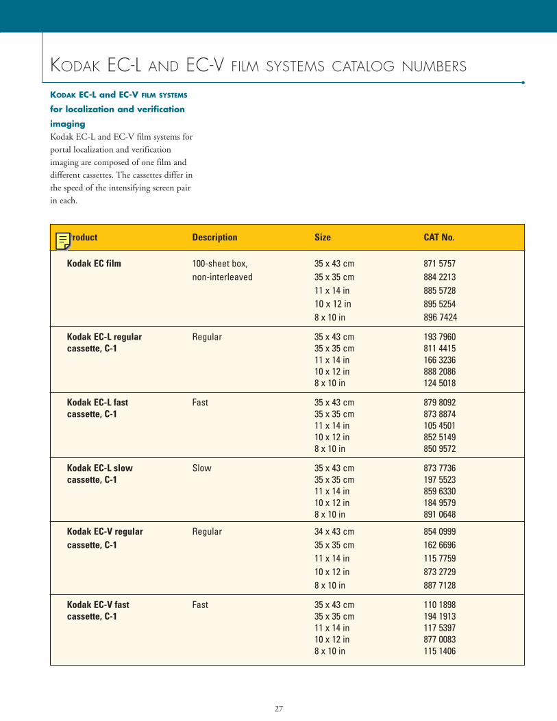
imagingKodak EC-L and EC-V film systems forportal localization and verification imaging are composed of one film anddifferent cassettes. The cassettes differ inthe speed of the intensifying screen pair in each.
Product Description Size CAT No.
Kodak EC film 100-sheet box, 35 x 43 cm 871 5757non-interleaved 35 x 35 cm 884 2213
11 x 14 in 885 572810 x 12 in 895 52548 x 10 in 896 7424
Kodak EC-L regular Regular 35 x 43 cm 193 7960cassette, C-1 35 x 35 cm 811 4415
11 x 14 in 166 323610 x 12 in 888 20868 x 10 in 124 5018
Kodak EC-L fast Fast 35 x 43 cm 879 8092cassette, C-1 35 x 35 cm 873 8874
11 x 14 in 105 450110 x 12 in 852 51498 x 10 in 850 9572
Kodak EC-L slow Slow 35 x 43 cm 873 7736cassette, C-1 35 x 35 cm 197 5523
11 x 14 in 859 633010 x 12 in 184 95798 x 10 in 891 0648
Kodak EC-V regular Regular 34 x 43 cm 854 0999cassette, C-1 35 x 35 cm 162 6696
11 x 14 in 115 775910 x 12 in 873 27298 x 10 in 887 7128
Kodak EC-V fast Fast 35 x 43 cm 110 1898cassette, C-1 35 x 35 cm 194 1913
11 x 14 in 117 539710 x 12 in 877 00838 x 10 in 115 1406
28
KODAK EC-L AND EC-V FILM SYSTEMS CATALOG NUMBERS (continued)
Using different KODAK EC-L SYSTEM
cassettes: slow, regular, & fast
Slow
The Kodak EC-L slow cassette consistsof a 1-mm copper-front screen and twophosphor-coated intensifying screensinside a Kodak x-ray cassette. This cas-sette may be appropriate to compensatefor beam energies higher than 6 MV,particularly 18 MV and higher. Usingthe same Kodak EC film in all three cassettes, this slow cassette requiresapproximately 30% more exposure vs.the Kodak EC-L regular cassettedescribed next.
Regular
The Kodak EC-L regular cassette con-sists of a 1-mm copper-front screen andtwo phosphor-coated intensifyingscreens. This cassette is designed for themajority of treatment images.
Fast
The Kodak EC-L fast cassette differsfrom the slow and regular cassettes in itscomplement of phosphor intensifyingscreens. These screens offer increasedspeed, allowing a reduction in exposureof approximately 30% vs. the Kodak EC-L regular cassette. This canbe particularly useful when imaging lateral pelvis fields and when dealingwith large patients.
KODAK EC-V verification system
for verification imagingThe Kodak EC-V verification system for verification imaging is composed of one film and two cassette/screen combinations.
All Kodak oncology film systemcassettes utilize the new Kodak X-Omatcassette, which offers reduced total cassette weight while providing equaldurability. As an example, the current 35 x 43-cm Kodak EC-L regular cassetteweighs approximately 8.3 pounds (3.8 kg). The same product in the new Kodak X-Omat cassette weighs approximately 7.1 pounds (3.2 kg). Nochange in current monitor unit settingsshould be required and the new cassetecan be used interchangeably with existing cassettes.
FOR MORE INFORMATION
• The Kodak Web site is another sourcefor more information on Kodak oncology products. The URL iswww.kodak.com/go/oncology.
• Health Imaging Customer SupportOperations can be reached at 1-800-328-2910; Outside the USA,call USA Area Code (716) 724-9362.
• Health Imaging automated fax backservice is available 24/7 by calling 1-800-328-2910. Outside the USA, the number is USA Area Code(716) 724-9362. An index of availablefax back documents (over 200) can beordered using the system.
• Kodak Environmental Services is aresource for health, safety, and environmental questions and concernswith Kodak products. Technical information is available by calling USAArea Code (716) 477-3194. The URLis www.kodak.com/go/kes.
29
INFORMATION NEEDED BY KODAK TO FACILITATE TROUBLESHOOTING
When contacting Kodak for assistancewith image-quality concerns, having asmuch of the following information as possible will facilitate all troubleshooting efforts:• Make and model of processor.• Mix of film types processed.• Volume of film (number of sheets per
typical eight-hour day).• Brand of chemicals (developer
and fixer).
• Type of chemicals (e.g., premixed,automixed, or facility mixed).
• Replenishment rates (milliliters ofdeveloper and fixer, fully defined interms of number and size of film, andlength of film travel, e.g., 80 millilitersof developer and 100 milliliters of fixerper one 35 x 43-cm Kodak EC film,35 cm of film travel).
• Dates last and previous preventivemaintenance (PM) of processor performed.
• Developer temperature.• Current and previous emulsion
numbers.• Date the change or problem
was noticed.• Description of change (what was
observed and who noticed it).• Description of any unusual
circumstances (e.g., films processedonly two days per week, etc.).
• Technical factors used.
References1. Hammoudah MM, Henschke U. Supervoltage beam films. Int J Radiat Oncol Biol Phys. 1977;2:571-577.2. Droege RT, Bjarngard BE. Influence of metal screens on contrast in megavoltage x-ray imaging. Med Phys. 1979;6:486-493.3. Droege RT, Bjarngard BE. Metal screen-film detector MTF at megavoltage x-ray energies. Med Phys. 1979;6:515-518.
Holmes TW, McCullough EC. Acceptance testing and quality assurance of automated scanning film densitometers used in the dosimetry of electron and photon therapy beams. Med Phys. 1983 Sep-Oct;10(5):698-700. Williamson JF, Khan FM, Sharma SC. Film dosimetry of megavoltage photon beams: a practical method of isodensity-to-isodose curve conversion. Med Phys. 1981 Jan-Feb;8(1): 94-8. Haus, AG. Through the Portal. Advance for Administrators in Radiology & Radiation Oncology. 2000; 10(10):63-67. Eastman Kodak Company. Health Imaging. In Focus Information for Medical Physicists. Vol. 7/1, Sept. 1999 Eastman Kodak Company. Health Imaging. In Focus Information for Medical Physicists. Vol. 6/1, 1998 Haus AG, Dickerson RE, Huff KE, et al. Evaluation of a cassette-screen-film combination for radiation therapy portal localization imaging with improvedcontrast. Med Phys. 24(10): 1605-1608, 1997. Dickerson RE, Haus AG, Huff KE. Development of a novel high-contrast cassette/film/screen system for radiation therapy portal localization imaging. Proc SPIE. 3032:520-529, 1997. Eastman Kodak Company. Health Imaging. Film Artifact Diagnostics Guide for KODAK X-OMAT Automatic Film Processors. CAT No. 132 7246, 4-23, 1996
www.kodak.com/go/health
HEALTH IMAGING
A B E T T E R V I E W O F L I F E .
Kodak, Lanex, Ready-Pack, X-Omat, and X-Omatic are trademarks of Eastman Kodak Company.All other trademarks are the property of their respective holders.Printed on recycled paper containing 10% post-consumer waste fiber, using soybean-based inks.N2-106 Printed in U.S.A. 10/01 ©Eastman Kodak Company, 2001 CAT No. 127 1030
Health Imaging DivisionEASTMAN KODAK COMPANY343 State StreetRochester, NY 14650-1132 USAPhone: 1-800-328-2910,option 3E-mail: [email protected]
KODAK CANADA INC.3500 Eglinton Avenue WestToronto, Ontario M6M 1V3CANADA
EASTMAN KODAK COMPANY305 Alexandra RoadSINGAPORE 159942Fax: (65) 473-3861E-mail: [email protected]
EASTMAN KODAK S.A.29-31 Route de l’AéroportCase PostaleCH-1212Geneve 15SwitzerlandTel: +41 22 799 31 01Fax: +41 22 799 31 07
KODAK JAPAN LTD.Yamaman Building6-1, Koamicho, Nihonbashi,Chuo-kuTOKYO 103-8540JAPANTel: 03-5644-5160www.kodak.co.jp/HI
EASTMAN KODAK COMPANYLatin American Region8600 NW 17th Street, Suite 200Miami, FL 33126-1006USAFax: 305-507-5055