Embed Size (px)
Citation preview

WARNING: DO NOT LUBRICATE THREADS, BOLT FAILURE MAY OCCUR DUE TO OVER TIGHTENING.WARNING: DO NOT DRILL OR WELD TO THIS HITCH.
INSTALLATION INSTRUCTIONSProduct No.
37096SMALL PARTSPACKAGE 37096F
SOLON, OHIO
IMPORTANT NOTESUSE ONLY REESE SUPPLIED OR APPROVED BOLTS, LOCKNUTS, AND WASHERS TO INSTALL THIS HITCH
CENTER SECTION ASSEMBLY
37096N 5-14-07 rev D PCN9668 © 2006-07 Cequent Towing Products Litho in China
GENERAL INSTRUCTIONS: 1. Remove center section from box and pull side plate assemblies from shipping location. Insert side plate assemblies
into hitch center section. Refer to specific instructions for proper position. Insert the coiled end of pull wire through hole on rear side of center section and through end of tube. Attach 1/4” bolt plate and 1/2 x 1-1/4 long carriage bolt as shown above. Pull fasteners through and loosely install 1/2 hex lock nut. Repeat steps for each fastener. The spare tire may need to be lowered to install the hitch. It will be replaced later.
2. Refer to the application chart to determine the correct installation for your vehicle. (Last page of each language)FOR ALL INSTALLATIONS: UNLESS OTHER WISE NOTED1. Torque all 3/8" nuts to 35 lb.ft. 5. Torque all 10mm CL10.9 hardware to 53 lb.ft.2. Torque all 12mm nuts & bolts to 65 lb.ft. 6. Torque all 5/8” hardware to 100 lb.ft.3. Torque all 1/2” hardware to 75 lb.ft 7. Torque all 14mm CL10.9 hardware to 115 lb.ft. 4. Torque (4) center section locknuts to 110 lb. ft. 8. Retighten the spare tire if it was loosened.
NOTE: Not all of the hardware will be used in every installation. Paint any bare metal to prevent rust.
TOOLS REQUIRED3/4” SOCKET & WRENCH9/16” SOCKET & WRENCH15MM, 17MM, 18 MM SOCKET19MM, 21MM, 22MM SOCKETTORQUE WRENCHSAFETY GLASSES
MULTI-FIT
SIDE PLATE ASSEMBLY (UP)
SEE SPECIFIC INSTRUCTIONSFOR PROPER SIDE PLATE ASSEMBLY POSITION(UP OR DOWN)
MUST INSTALL REAR SIDE BOLT FIRST
1/2” x 1 1/4” CARRIAGE BOLT1/4” x 1” x 2” BOLT PLATE
1/2” HEX LOCKNUT
For Installation Assistance or Technical Help, See our Web Site at www.reesetowpower.com or call 1-800-428-7303
PULL WIRE(SUPPLIED)
CENTER SECTION
CENTER SECTION LOCKNUT
CENTER SECTIONLOCK NUT

FASTENER KIT CONTAINS THE BELOW ITEMSLa trousse de visserie contient les éléments ci-dessous
El kit de tornillos contiene los siguientes artículos
Qty. Qté.Ctd. (4)
-CENTER SECTION LOCK NUT 1/2-13
- CONTRE-ÉCROU DESECTION CENTRALE 1/2-13 PO-CONTRATUERCA DE LA SECCIÓN CENTRAL 1/2-13
Qty. Qté.Ctd.(2)
- HEX HEAD BOLT M14 X 2.00 X 45mm CL 10.9
- BOULON HEXAGONAL M14 X 2.00 X 45MM - CL10.9
- PERNO HEXAGONAL M14 X 2.00 X 45mm - CL10.9
Qty. Qté.Ctd.(4)
- CARRIAGE BOLT 1/2-13 X 1.25” - GR 8
- BOULON DE CARROSSERIE 1/2 x 1 1/4 PO - GR8
- PERNO DE CARRUAJE 1/2" x 1 1/4“ –GR8
Qty. Qté. Ctd.(4)
- BOLT PLATE 1/4” X 1.5” X 3”
- PLAQUE DE BOULON 1/4 x 1-1/2 x 3 po
- PLACA DE PERNO 1/4" x 1-1/2" x 3"
Qty. Qté.Ctd.(2)
- LOCK WASHER 1/2”
- RONDELLE FREIN 1/2 po
- ARANDELA DE BLOQUEO 1/2"
Qty. Qté. Ctd.(2)
- HEX NUT M12 X 1.75 CL 8
- ÉCROU M12 X 1.75 CL 8
- TUERCA M12 X 1.75 CL 8
Qty. Qté.Ctd.(2)
- LOCKWASHER 9/16”
- RONDELLE FREIN 9/16 po
- ARANDELA DE BLOQUEO 9/16"
Qty. Qté. Ctd.(8)
- BOLT PLATE 3/8” X 1.25” X 2.5”
- PLAQUE DE BOULON 3/8 x 1-1/4 x 2 ½po
- PLACA DE PERNO 3/8" x 1-1/4" x 2 1/2"
Qty. Qté.Ctd.(2)
- CARRIAGE BOLT 1/2-13 X 2.25” - GR 5
- BOULON DE CARROSSERIE 1/2 X 2-1/4 po – GR5
- PERNO DE CARRUAJE 1/2" X 2 1/4“-GR5
Qty. Qté.Ctd.(4)
- BOLT PLATE 1/4” X 1.0” X 1.5”
- PLAQUE DE BOULON 1/4 x 1 x 1 ½ po
- PLACA DE PERNO 1/4" x 1" x 1 1/2"
Qty. Qté.Ctd.(8)
- HEX HEAD BOLT 3/8-16 X 1.25” – GR5
- BOULON HEXAGONAL 3/8 x 1-1/4 po- GR5
- PERNO HEXAGONAL 3/8" x 1 1/4 – GR5
Qty. Qté. Ctd.(4)
- BOLT PLATE 1/4” X 1.0” X 2.0”
- PLAQUE DE BOULON 1/4 x 1 x 2 po
- PLACA DE PERNO 1/4" x 1" x 2"
Qty. Qté.Ctd.(2)
- HEX HEAD BOLT 1/2”-13 X 2.25” - GR 5
- BOULON HEXAGONAL 1/2 x 2 ¼ po-GR5
- PERNO HEXAGONAL 1/2" x 2 1/4“– GR5
Qty. Qté. Ctd.(4)
- HEX NUT 1/2” – 13
- ÉCROU ½ po
- TUERCA 1/2"
Qty. Qté.Ctd.(6)
- CONICAL WASHER 1/2”
- RONDELLE CONIQUE ½ po
- ARANDELA CÓNICA 1/2"
Qty. Qté.Ctd.(4)
- FLAT WASHER 3/8
- RONDELLE PLATE 3/8 po
- ARANDELA PLANA 3/8
Qty. Qté.Ctd.(2)
- HEX HEAD BOLT M12 X 1.75 X 45mm- CL 10.9
- BOULON HEXAGONAL M12 X 1.75 X 45mm- CL 10.9
- PERNO HEXAGONAL M12 X 1.75 X 45mm – CL10.9
Qty. Qté. Ctd.(8)
- WASHER NUTS 3/8 – 16
- ÉCROUS À RONDELLE 3/8 po
- TUERCAS CON ARANDELA 3/8"(MET
RIC
)
(MET
RIC
)(M
ETR
IC)

INSTALLATION ATOOLS REQUIRED
9/16”, 3/4” SOCKET21MM SOCKETTORQUE WRENCHSAFETY GLASSES
VEHICLE FRAME
1/4” x 1-1/2” x 3”BOLT PLATE
HOLE 5
HOLE 2
3/8” x 1 1/4 bolt
3/8” WASHER NUTS
SIDE PLATE ASSEMBLY
CENTER SECTION
HITCH SIDE BRACKET
3/8” x 1-1/4” x 2 1/2”BOLT PLATE
1/2” X 2 1/4” CARRIAGE BOLT
M14 X 45MM CL10.9 BOLT
EXISTING WELDNUT ONBUMPER BRACKET
1/2” CONICAL WASHER
1/2” NUT
9/16” LOCK WASHER
3/8” x 1-1/4” x 2 1/2”BOLT PLATE
NOTE:General assembly - loosely assemble center section (page 1); loosely install side brackets on vehicle (this page);install center section assembly; tighten all fasteners to proper specifications (page 1)
99-07 CHEVROLET SILVERRADO/ GMC SIERRA 1500 PICKUP (07 - CLASSIC ONLY)
1. Remove the two (2) rear M14 bumper bracket bolts.2. Raise hitch side brackets into position, aligning hole 2 in bracket with the rear most weldnut in frame.3. Install the M14 X 45 MM hex bolt, 9/16” lock washer, and 3/8” bolt plate though hole 2 and into weldnut in
frame, both sides, finger tight.4. Install 1/2” x 2 1/4” carriage bolt and block into forward hole of frame that aligns with hole 5 in hitch side
bracket, as shown.5. Install 3/8” bolt plate, 1/2” conical washer and nut, both sides, finger tight.6. Install center section as pre-assembled on front page with (4) 3/8” x 1 ¼” bolts and washer nuts, both sides.
Align center section of hitch with center of vehicle. Finger tighten fasteners.7. Tighten hitch side bracket to frame. Tighten side plate assembly to side bracket. Tighten side bracket
assembly to center section.
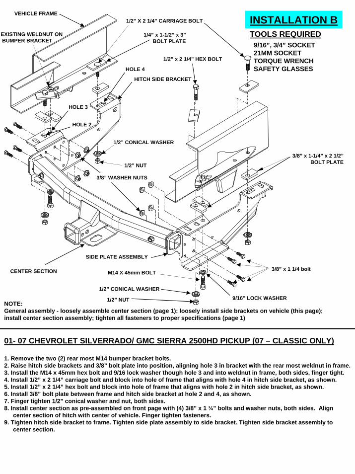
INSTALLATION BTOOLS REQUIRED
9/16”, 3/4” SOCKET21MM SOCKETTORQUE WRENCHSAFETY GLASSES
VEHICLE FRAME
1/4” x 1-1/2” x 3”BOLT PLATE
HOLE 4
HOLE 2
3/8” x 1 1/4 bolt
3/8” WASHER NUTS
SIDE PLATE ASSEMBLY
CENTER SECTION
HITCH SIDE BRACKET
NOTE:General assembly - loosely assemble center section (page 1); loosely install side brackets on vehicle (this page);install center section assembly; tighten all fasteners to proper specifications (page 1)
3/8” x 1-1/4” x 2 1/2”BOLT PLATE
1/2” X 2 1/4” CARRIAGE BOLT
M14 X 45mm BOLT
EXISTING WELDNUT ONBUMPER BRACKET
1/2” CONICAL WASHER
1/2” NUT
HOLE 3
1/2” NUT
1/2” CONICAL WASHER9/16” LOCK WASHER
1/2” x 2 1/4” HEX BOLT
01- 07 CHEVROLET SILVERRADO/ GMC SIERRA 2500HD PICKUP (07 – CLASSIC ONLY)
1. Remove the two (2) rear most M14 bumper bracket bolts.2. Raise hitch side brackets and 3/8” bolt plate into position, aligning hole 3 in bracket with the rear most weldnut in frame.3. Install the M14 x 45mm hex bolt and 9/16 lock washer though hole 3 and into weldnut in frame, both sides, finger tight.4. Install 1/2” x 2 1/4” carriage bolt and block into hole of frame that aligns with hole 4 in hitch side bracket, as shown.5. Install 1/2” x 2 1/4” hex bolt and block into hole of frame that aligns with hole 2 in hitch side bracket, as shown.6. Install 3/8” bolt plate between frame and hitch side bracket at hole 2 and 4, as shown.7. Finger tighten 1/2” conical washer and nut, both sides.8. Install center section as pre-assembled on front page with (4) 3/8” x 1 ¼” bolts and washer nuts, both sides. Align
center section of hitch with center of vehicle. Finger tighten fasteners.9. Tighten hitch side bracket to frame. Tighten side plate assembly to side bracket. Tighten side bracket assembly to
center section.

INSTALLATION CTOOLS REQUIRED
9/16”, 3/4” SOCKET18MM SOCKETTORQUE WRENCHSAFETY GLASSES
VEHICLE FRAME
1/4” x 1-1/2” x 3”BOLT PLATE
HOLE 5
HOLE 1
3/8” x 1 1/4 bolt
3/8” WASHER NUTS
SIDE PLATE ASSEMBLY
CENTER SECTION
HITCH SIDE BRACKET
NOTE:General assembly - loosely assemble center section (page 1); loosely install side brackets on vehicle (this page);install center section assembly; tighten all fasteners to proper specifications (page 1)
3/8” x 1-1/4” x 2 1/2”BOLT PLATE
1/2” X 2 1/4” CARRIAGE BOLT
1/2” CONICAL WASHER
1/2” NUT
1/2” CONICAL WASHER
1/2” NUT
3/8” x 1-1/4” x 2 1/2”BOLT PLATE
1/2” CONICAL WASHER
1/2” NUT
1/2” x 2 1/4” HEX BOLT
3/8” x 1-1/4” x 2 1/2”BOLT PLATE
M12 NUT
1/2” CONICAL WASHER
M12 X 45MM BOLT
1/4” X 1” X 1 1/2”BOLT PLATE
HOLE 4
EXISTING HOLES
97-04 FORD F-150 PICKUP (OLD BODY STYLE)
1. Lower spare tire.2. Place 1/2” x 2 1/4” bolts and 1/4” bolt plate in rear most hole in frame. Both sides.3. Aligning hole 1 in bracket with the rear most hole in frame. Raise hitch side bracket, 3/8” bolt plate, 1/2”
conical washer, and 1/2” nut into position, both sides. loosely install nut.4. Install the 1/2” x 2 1/4” carriage bolt and 1/4” bolt plate though hole in frame that aligns with hole 5 in hitch
side bracket. Install 3/8” bolt plate, 1/2” conical washer and 1/2” nut, both sides, loosely install nut.5. Install the M12 x 45mm hex bolt and 1/4” bolt plate though hole in frame that aligns with hole 4 in hitch side
bracket. Install 1/2” conical washer and m12 nut, both sides, finger tight.6. Install center section as pre-assembled on front page with (4) 3/8” x 1 ¼” bolts and washer nuts, both sides.
Align center section of hitch with center of vehicle. Finger tighten fasteners.7. Tighten hitch side bracket to frame. Tighten side plate assembly to side bracket. Tighten side bracket
assembly to center section.8. Raise spare tire back into place.

2 1/2"
1 5/16"
1 5/8"
14 5/8"
NOTE:General assembly - loosely assemble center section (page 1);loosely install side brackets on vehicle (this page);
install center section assembly; tighten all fasteners to proper specifications (page 1)
2004 - 05 FORD F-150 (NEW BODY STYLE) WITHOUT VIBRATION DAMPENER ON FRAME1. Lower spare tire for ease of installation.2. Apply masking tape to the bottom of frame in area “A” and area “B”. Same on both frame rails.3. Measure from the outside of the frame inward 1 5/16” and make a line the length of area “A”.4. Measure from the outside of the frame inward 1 5/8” and make a line the length of area “B”.5. Measure from rear of spring shackle 2 1/2” and make a mark in area “A” . From that mark, measure 14 5/8” forward and make a mark in
area “B”.6. Hold side bracket up to bottom of frame. Double check hole 2 and 5 in side bracket for proper alignment with marks. If they don’t line up,
adjust the marks in area “B”.7. Center punch and pilot drill with 1/4” drill bit . Total of 4 holes ( 2 per frame rail). Enlarge the pilot hole with 9/16” drill bit.8. Loosely install side brackets as shown. Include the angle reinforcement on the inside of the frame and 3/8” blocks under the frame as
shown.9. Using the top slot of the frame angle reinforcement placed inside the frame in step 8. Drill a 1/2” hole in the side of the frame as far
forward as slot will permit.10. Install the M-12 fasteners through the frame side as shown and finger tighten.11. Between side plate assembly and hitch side bracket tape (2) 1/4” bolt plate and (2) 3/8” washer (see photo). This will shift the side
bracket on an angle that follows the vehicles frame, both sides.12. Install center section as pre-assembled on front page and shown above with (4) 3/8” x 1 ¼” bolts and washer nuts, both sides. Align
center section of hitch with center of vehicle. Finger tighten fasteners.13. Tighten hitch side bracket and angle reinforcement to frame. Tighten side plate assembly to side bracket. Tighten side bracket assembly
to center section.14. Raise spare tire back into place.
AREA “A”
AREA “B”
REAR OF FRAME
(VIEW OF BOTTOM PASSENGER SIDE FRAME)
TOOLS REQUIRED1/4” ,1/2”,& 9/16” DRILL BIT9/16”, 3/4” SOCKET, WRENCH18MM,19MM SOCKET, WRENCHTORQUE WRENCH
DRILLED HOLE
DRILLED HOLE
DRILLED HOLE
HOLE 5
HOLE 2
1/2” x 2 1/4”CARRAIGE BOLT
1/4” x 1 1/2” x 3”BOLT PLATEFRAME ANGLE
REINFORCEMENT
1/2” LOCK-WASHER12MM NUT
3/8” SPACER
1/2” CONICAL WASHER
1/2” NUT
1/2” CONICALWASHER
1/2” NUT
3/8” X 1 1/4”BOLTS
3/8” WASHER NUTS
1/2” x 2 1/4” HEX BOLT
12MM HEX BOLT
1/2” CONICAL WASHER
INSTALLATION D
1/4” x 1 1/2” x 3”BOLT PLATE
3/8” FLAT WASHER
1/4” X 1” X 1 1/2”BOLT PLATE SIDE PLATE ASSEMBLY
CENTER SECTION
HITCH SIDE BRACKET
TAPE
FORWARD
SPRINGSHACKLE
SPRINGSHACKLE

INSTALLATION ETOOLS REQUIRED
9/16”, 3/4” SOCKET1/2” DRILL BIT18MM SOCKETTORQUE WRENCHSAFETY GLASSES
VEHICLE FRAME
1/4” x 1-1/2” x 3”BOLT PLATE
HOLE 1
3/8” x 1 1/4 bolt
3/8” WASHER NUTS
SIDE PLATE ASSEMBLY
CENTER SECTION
HITCH SIDE BRACKET
NOTE:General assembly - loosely assemble center section (page 1); loosely install side brackets on vehicle (this page);install center section assembly; tighten all fasteners to proper specifications (page 1)
3/8” x 1-1/4” x 2 1/2”BOLT PLATE
1/2” X 2 1/4” CARRIAGE BOLT
1/2” NUT
1/2” CONICAL WASHER
1/2” CONICAL WASHER
1/2” NUT
1/2” x 2 1/4” HEX BOLT
3/8” x 1-1/4” x 2 1/2”BOLT PLATEM12 NUT
M12 X 45MM BOLT
1/4” X 1” X 1 1/2”BOLT PLATE
HOLE 4
EXISTING HOLES
DRILLED HOLE
HOLE 3
99-04 FORD F-250, F-350 SUPER DUTY PICKUP
1. Lower spare tire.2. Place 1/2” x 2 1/4” bolts and 1/4” bolt plates in noted existing holes in frame. Both sides.3. Aligning hole 3 and 4 in bracket with bolts in frame. Raise hitch side bracket, 3/8” bolt plate, 1/2” conical washer, and
1/2” nut into position, as shown, both sides. loosely install nuts.4. Using hole 1 in bracket as a guide, drill a 1/2” hole in frame.5. Install the M12 x 45mm hex bolt and 1/4” bolt plate though hole in frame. Install 1/2” conical washer and M12 nut, both
sides, finger tight.6. Install center section as pre-assembled on front page with (4) 3/8” x 1 ¼” bolts and washer nuts, both sides. Align
center section of hitch with center of vehicle. Finger tighten fasteners.7. Tighten hitch side bracket to frame. Tighten side plate assembly to side bracket. Tighten side bracket assembly to
center section.8. Raise spare tire back into place.

INSTALLATION FTOOLS REQUIRED
9/16”, 3/4” SOCKET1/2” DRILL BIT18MM SOCKETTORQUE WRENCHSAFETY GLASSES
NOTE:General assembly - loosely assemble center section (page 1); loosely install side brackets on vehicle (this page);install center section assembly; tighten all fasteners to proper specifications (page 1)
VEHICLE FRAME
1/4” x 1-1/2” x 3”BOLT PLATE
HOLE 1
3/8” x 1 1/4” BOLT
3/8” WASHER NUTS
SIDE PLATE ASSEMBLY
CENTER SECTION
HITCH SIDEBRACKET
3/8” x 1-1/4” x 2 1/2”BOLT PLATE
1/2” X 2 1/4”CARRIAGE BOLT
1/2” NUT
1/2” CONICAL WASHER
1/2” CONICAL WASHER1/2” NUT
1/2” x 2 1/4” HEX BOLT
3/8” x 1-1/4” x 2 1/2”BOLT PLATE
M12 NUT
M12 X 45MM BOLT
HOLE 4
EXISTING HOLES
DRILLED HOLE ON SOME MODELS
HOLE 3
DRILLED HOLE
1/2” CONICAL WASHER
1/4” x 1-1/2” x 3” BOLT PLATE
1/4” X 1” X 1 1/2”BOLT PLATE
1/4” x 1-1/2” x 3”BOLT PLATE
1/4” X 1” X 1 1/2”BOLT PLATE
3/8” x 1-1/4” x 2 1/2”BOLT PLATE
1/2” x 2 1/4”HEX BOLT
M12 X 45MM BOLT
1/2” X 2 1/4”CARRIAGE BOLT
3/8” x 1 1/4BOLT
FRAME CROSS MEMBER
SUSPENSION SUPPORT(HEAVY DUTY MODELS ONLY)
94-01 DODGE 1500 PICKUP, 94-02 DODGE 2500 & 3500 PICKUP (SHORT BED)
1. Lower spare tire.2. Place 1/2” x 2 1/4” carriage bolts and 1/4” bolt plates in noted existing large hole in end of frame. Both sides.3. Aligning hole 1 in bracket with bolts in frame. Raise 3/8” bolt plate, hitch side bracket, 1/4” bolt plate, 1/2” conical
washer, and 1/2” nut into position, as shown, both sides. loosely install nuts.4. Pull both hitch side brackets to the rear most of hole in frame.5. If the vehicle frame has a hole that lines up with hole #4 in hitch side bracket, install fasteners and bolt plates as shown.
If hole doesn’t exist or is to small, drill 1/2” hole in vehicle frame, approximatly centered in #4 hole if small hole doesn’t exist. Install fasteners and bolt plates as shown.
6. Using hole 3 in bracket as a guide, drill a 1/2” hole in frame. Make sure that there is enough room to place 1/4 x 1 x 1 1/2”bolt plate flat on the inside of the frame, next to the frame cross member.
7. Install the M12 x 45mm hex bolt and 1/4” bolt plate though hole in frame. Install 3/8” bolt plate, 1/2” conical washer and M12 nut as shown, both sides, finger tight.
8. Install center section as pre-assembled on front page with (4) 3/8” x 1 ¼” bolts and washer nuts, both sides. Align center section of hitch with center of vehicle. Finger tighten fasteners.
9. Tighten hitch side bracket to frame. Tighten side plate assembly to hitch side bracket. Tighten side plate assembly to center section.
10. Raise spare tire back into place.

INSTALLATION GTOOLS REQUIRED
9/16”, 3/4” SOCKET1/2” DRILL BIT18MM SOCKETTORQUE WRENCHSAFETY GLASSES
NOTE:General assembly - loosely assemble center section (page 1); loosely install side brackets on vehicle (this page);install center section assembly; tighten all fasteners to proper specifications (page 1)
VEHICLE FRAME
1/4” x 1-1/2” x 3”BOLT PLATE
HOLE 1
3/8” x 1 1/4” BOLT
3/8” WASHER NUTS
SIDE PLATE ASSEMBLY
CENTER SECTION
HITCH SIDEBRACKET
3/8” x 1-1/4” x 2 1/2”BOLT PLATE
1/2” X 2 1/4”CARRIAGE BOLT
1/2” NUT
1/2” CONICAL WASHER
1/2” CONICAL WASHER1/2” NUT
1/2” x 2 1/4” HEX BOLT
3/8” x 1-1/4” x 2 1/2”BOLT PLATE
M12 NUT
M12 X 45MM BOLT
HOLE 4
EXISTING HOLES
DRILLED HOLE ON SOME MODELS
HOLE 3
DRILLED HOLE
1/2” CONICAL WASHER
1/4” x 1-1/2” x 3” BOLT PLATE
1/4” X 1” X 1 1/2”BOLT PLATE
1/4” x 1-1/2” x 3”BOLT PLATE
1/4” X 1” X 1 1/2”BOLT PLATE
3/8” x 1-1/4” x 2 1/2”BOLT PLATE
1/2” x 2 1/4”HEX BOLT
M12 X 45MM BOLT
1/2” X 2 1/4”CARRIAGE BOLT
3/8” x 1 1/4BOLT
FRAME CROSS MEMBER
SUSPENSION SUPPORT(HEAVY DUTY MODELS ONLY)
94-01 DODGE 1500 PICKUP, 94-02 DODGE 2500 & 3500 PICKUP (LONG BED)
1. Lower spare tire.2. Place 1/2” x 2 1/4” carriage bolts and 1/4” bolt plates in noted existing large hole in end of frame. Both sides.3. Aligning hole 1 in bracket with bolts in frame. Raise 3/8” bolt plate, hitch side bracket, 1/4” bolt plate, 1/2” conical
washer, and 1/2” nut into position, as shown, both sides. loosely install nuts.4. Pull both hitch side brackets to the forward most of hole in frame.5. If the vehicle frame has a hole that lines up with hole #4 in hitch side bracket, install fasteners and bolt plates as shown.
If hole doesn’t exist or is to small, drill 1/2” hole in vehicle frame, approximatly centered in #4 hole. Install fasteners and bolt plates as shown.
6. Using hole 3 in bracket as a guide, drill a 1/2” hole in frame. Make sure that there is enough room to place 1/4 x 1 x 1 1/2”bolt plate flat on the inside of the frame.
7. Install the M12 x 45mm hex bolt and 1/4” bolt plate though hole in frame. Install 3/8” bolt plate, 1/2” conical washer and M12 nut as shown, both sides, finger tight.
8. Install center section as pre-assembled on front page with (4) 3/8” x 1 ¼” bolts and washer nuts, both sides. Align center section of hitch with center of vehicle. Finger tighten fasteners.
9. Tighten hitch side bracket to frame. Tighten side plate assembly to hitch side bracket. Tighten side plate assembly to center section.
10. Raise spare tire back into place.

3/8” x 1 1/4 bolt
CENTER SECTION
1/2” X 2 1/4”HEX BOLT
1/2” CONICAL WASHER
3/8” WASHER NUTS
SIDE PLATE ASSEMBLY
HITCH SIDE BRACKET
3/8” x 1-1/4” x 2 1/2”BOLT PLATE HOLE 2
(SHORT BED)
HOLE 5(SHORT BED)
VEHICLE FRAME
HOLE 4(LONG BED)
HOLE 1(LONG BED)
1/2” NUT
1/4” x 1” x 3” BOLT PLATE
3/8” x 1-1/4” x 2 1/2”BOLT PLATE
3/8” x 1-1/4” x 2 1/2”BOLT PLATE
1/2” CONICAL WASHER
1/2” X 2 1/4” CARRIAGE BOLT
HOLE 3
INSTALLATION HTOOLS REQUIRED
9/16”, 3/4” SOCKETTORQUE WRENCHSAFETY GLASSES
NOTE:General assembly - loosely assemble center section (page 1); loosely install side brackets on vehicle (this page);install center section assembly; tighten all fasteners to proper specifications (page 1)
88-00 CHEVY & GMC C/K PICKUP SERIES (CLASSIC):
1. Lower spare tire.2. If your vehicle has rivets on the bottom of the frame, you will need to install one 3/8” thick spacer between the frame and hitch side
bracket at each bolting location. These are needed for clearance between the bracket and the rivet head. The bracket cannot be bolted directly against the rivets.
3. Install 1/2” X 2 1/4” hex bolt, 1/2” conical washer, and 3/8” thick spacer with the head on the bottom of the frame. Finger tighten 1/2”conical washer and 1/2” nut on each bolt. For short beds use hole 2. For long beds use hole 1. NOTE: SOME DUAL PIPE EXHAUST SYSTEMS WILL HIT THE BRACKET. THE EXHAUST WILL NEED TO BE MODIFIED.
4. Short Beds: Insert 1/2” carriage bolts with bolt plates down through the 1” diameter hole in the frame and into hole 5 in the hitch side bracket. Finger tighten 1/2” conical washer and 1/2” nut on each bolt.
5. Long Beds: Insert 1/2” carriage bolts with bolt plates down through the 1” diameter hole in the frame and into hole 4 in the hitch side bracket. Finger tighten 1/2” conical washer and 1/2” nut on each bolt.
6. Install center section as pre-assembled on front page with (4) 3/8” X 1 1/4” bolts and washer nuts, both sides. Align center section of hitch with center of vehicle. Finger tighten fasteners.
7. Tighten hitch side brackets to vehicle frame. Tighten side plate assemblies to side brackets. Tighten side bracket assemblies to center section. Refer to front page for specified torque values.
8. Raise spare tire back into place.9. Be sure the spare tire in not rubbing against the brake hose. If needed, bend the hose mounting bracket to ensure proper clearance.

VEHICLE FRAME
HOLE 5
HOLE 2
3/8” x 1 1/4 bolt
CENTER SECTION
1/4” x x 1” x 1 1/2”BOLT PLATE
12MM HEX BOLT
M12 NUT
1/2” X 2 1/4”HEX BOLT
1/4” x 1” x 1 1/2”BOLT PLATE
1/2” CONICAL WASHER
1/2” NUT
3/8” x 1-1/4” x 2 1/2”BOLT PLATE
3/8”WASHER
NUTSSIDE PLATE ASSEMBLY
HITCH SIDE BRACKET
3/8” x 1-1/4” x 2 1/2”BOLT PLATE
1/2” CONICAL WASHER
3/8” x 1-1/4” x 2 1/2”BOLT PLATE
INSTALLATION ITOOLS REQUIRED
9/16”, 3/4”, 18MM SOCKET1/4”, 1/2” DRILL BIT1/2” DRILLTORQUE WRENCHSAFETY GLASSES
NOTE:BOTTOM VIEW OF DRIVER SIDE FRAME
AREA “B”1/2” DRILLED HOLE
AREA “A”1/2” DRILLED HOLE
FORWARD
REAR OF FRAME
RIVET
General assembly - loosely assemble center section (page 1); loosely install side brackets on vehicle (this page);install center section assembly; tighten all fasteners to proper specifications (page 1)
87-96 Ford Full Size Pickup & 1997 F-250 Heavy Duty / F-350 Heavy Duty:
1. Lower spare tire.2. Apply masking tape to the bottom of frame in area “A” and area “B”. Same on both frame rails.3. Measure from the outside of the frame inward 1” and make a line in area “A” and area “B”.4. Measure from the rear of the frame forward 3/4” and make a line in area “A”. From that mark, measure 14 5/8” forward and make a
mark in area “B”.5. Hold side bracket up to bottom of frame. Double check hole 2 and 5 in side bracket for proper alignment with marks. If they don’t line
up, adjust the marks in area “B”. 6. Center punch and pilot drill with 1/4” drill bit. Enlarge the pilot hole with 1/2” drill bit. Total of 4 holes ( 2 per frame rail).7. Install 12MM hex bolt and block into the hole of frame that aligns with hole 5 in hitch side bracket, as shown.8. Install 1/2” X 2 1/4” hex bolt and block into the hole of frame that aligns with hole 2 in hitch side bracket, as shown.9. Install 3/8” bolt plate between frame and hitch side bracket at hole 2 and 5, as shown.10. At hole 2, place 3/8” bolt plate underneath hitch side bracket and finger tighten 1/2” conical washer and nut, both sides. 11. At hole 5, finger tighten 1/2” conical washer and nut, both sides. 12. Install center section as pre-assembled on front page with (4) 3/8” X 1 1/4” bolts and washer nuts, both sides. Align center section of
hitch with center of vehicle. Finger tighten fasteners.13. Tighten hitch side brackets to vehicle frame. Tighten side plate assemblies to side brackets. Tighten side bracket assemblies to
center section. Refer to front page for specified torque values.14. Raise spare tire back into place.
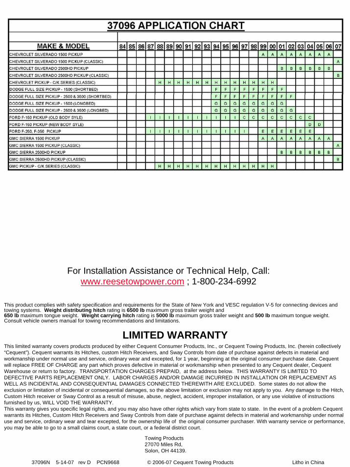
For Installation Assistance or Technical Help, Call: www.reesetowpower.com ; 1-800-234-6992
This product complies with safety specification and requirements for the State of New York and VESC regulation V-5 for connecting devices and towing systems. Weight distributing hitch rating is 6500 lb maximum gross trailer weight and 650 lb maximum tongue weight. Weight carrying hitch rating is 5000 lb maximum gross trailer weight and 500 lb maximum tongue weight. Consult vehicle owners manual for towing recommendations and limitations.
This limited warranty covers products produced by either Cequent Consumer Products, Inc., or Cequent Towing Products, Inc. (herein collectively “Cequent”). Cequent warrants its Hitches, custom Hitch Receivers, and Sway Controls from date of purchase against defects in material andworkmanship under normal use and service, ordinary wear and excepted, for 1 year, beginning at the original consumer purchase date. Cequent will replace FREE OF CHARGE any part which proves defective in material or workmanship when presented to any Cequent dealer, Cequent Warehouse or return to factory. TRANSPORTATION CHARGES PREPAID, at the address below. THIS WARRANTY IS LIMITED TO DEFECTIVE PARTS REPLACEMENT ONLY. LABOR CHARGES AND/OR DAMAGE INCURRED IN INSTALLATION OR REPLACEMENT AS WELL AS INCIDENTAL AND CONSEQUENTIAL DAMAGES CONNECTED THEREWITH ARE EXCLUDED. Some states do not allow the exclusion or limitation of incidental or consequential damages, so the above limitation or exclusion may not apply to you. Any damage to the Hitch, Custom Hitch receiver or Sway Control as a result of misuse, abuse, neglect, accident, improper installation, or any use violative of instructions furnished by us, WILL VOID THE WARRANTY.This warranty gives you specific legal rights, and you may also have other rights which vary from state to state. In the event of a problem Cequent warrants its Hitches, Custom Hitch Receivers and Sway Controls from date of purchase against defects in material and workmanship under normal use and service, ordinary wear and tear excepted, for the ownership life of the original consumer purchaser. With warranty service or performance, you may be able to go to a small claims court, a state court, or a federal district court.
Towing Products27070 Miles Rd, Solon, OH 44139.
LIMITED WARRANTY
37096N 5-14-07 rev D PCN9668 © 2006-07 Cequent Towing Products Litho in China

IMPORTANT INFORMATION ON TOWINGTOWING EQUIPMENT OWNERS: Make sure all operators of your equipment read and understand this information before towing. Save for reference. This will help you properly select, use, and maintain your towing equipment. Refer to owner's manuals for your tow vehicle, trailer, and other parts of your towing system. Learn the capabilities and limitations of each part. GROSS TRAILER WEIGHT and TONGUE WEIGHT are two of the most important items to consider. THESE WEIGHTS MUST NEVER EXCEED THE LOWEST RATING OF ANY PART OF YOUR TOWING SYSTEM. GROSS TRAILER WEIGHT is the weight of the trailer plus all cargo.Measure GROSS TRAILER WEIGHT with the fully loaded trailer on a level surface. The WEIGHT is the downward force exerted on the ball by the trailer coupler. Measure TONGUE WEIGHT with the fully loaded trailer on a level surface. The coupler must be at its normal towing height. Use a commercial scale or a bathroom scale. Set up the bathroom scale as shown for heavy tongue weights.
YOUR TOWING EQUIPMENTMETHOD FOR MEASURING GROSS TRAILER WEIGHT METHOD FOR MEASURING TRAILER TONGUE WEIGHT
SAFE TOWING TIPSTRAILER HITCHES, RECEIVERS, AND BALL MOUNTSSelect these products by their gross trailer weight and tongue weight ratings. Select hitches and receivers for specific vehicles.
HITCH BALLSSelect by gross trailer weight rating, mounting platform thickness, hole size,and coupler socket size. Platform must be at least 3/8 inch thick. Holemust not exceed threaded shank diameter by more than 1/16 inch. Use lockwasher. Tighten per instructions. When tightened, shank must protrudebeyond bottom of nut. Gross trailer weight rating and ball diameter aremarked on REESE balls.
TRAILER COUPLERSThe coupler socket should be smooth, clean, and lightly lubricated.Tighten or adjust per coupler manufacturer's instructions.
SAFETY CHAINSConnect safety chains properly EVERY TIME YOU TOW. Cross chainsunder coupler. Attach securely to the hitch or tow vehicle so they can'tbounce loose. Leave only enough slack to permit full turning. Too muchslack may prevent chains from maintaining control if other connectionsseparate. Don't let chains drag on the road.
TRAILER LIGHTS, TURN SIGNALS, ELECTRIC BRAKES, ANDBREAK AWAY SWITCH CONNECTIONSMake these safety-critical connections EVERY TIME YOU TOW, no matterhow short the trip. Check operation, including electric brake manual control,before getting on the road.
SWAY CONTROLSSway controls can lesson the effects of sudden maneuvers, wind gusts, andbuffeting caused by other vehicles. We recommend them for trailers withlarge surface areas, such as travel trailers. Adjustable friction models canhelp control trailers with low tongue weight percentage.
OTHER USEFUL EQUIPMENTAIR SPRINGS, AIR SHOCKS, or HELPER SPRINGS are useful for somehitch applications. A TRANSMISSION COOLER may be necessary forheavy towing. Many states require TOWING MIRRORS on both sides.
TIRE INFLATIONCheck often. Follow tow vehicle and trailer manufacturers' recommendation. Improper tire inflation can cause trailer sway.
CHECK YOUR EQUIPMENT / REPLACE WORN PARTSCheck ball, coupler, chains, retaining pins and clips, and all otherconnections EVERY TIME YOU TOW. Re-check at fuel and rest stops.
NO PASSENGERS IN TRAILERS!NEVER allow people in trailers while towing, under any circumstances.
TRAILER LOADINGProper loading helps prevent sway. Place heavy object on the floorahead of the axle. Balance the load side-to-side. Secure it toprevent shifting. Tongue weight should be 10-15 percent of grossweight for most trailers. Too low a percentage of tongue weight cancause sway. NEVER load the trailer rear-heavy. LOAD THETRAILER HEAVIER IN FRONT.
DRIVING The additional weight of a trailer affects acceleration, braking andhandling. Allow extra time for passing, stopping, and changing lanes.Severe bumps can damage your towing vehicle, hitch, and trailer.Drive slowly on rough roads. STOP AND MAKE A THOROUGHINSPECTION IF ANY PART OF YOUR TOWING SYSTEMSTRIKES THE ROAD. CORRECT ANY PROBLEMS BEFORERESUMING TRAVEL.
CHECK FOR EXCESSIVE SWAY AND ELIMINATE ITExcessive sway can lead to loss of control. Sway motion shouldsettle out quickly. Sway tends to increase on a downgrade. Startingslowly, increase speed in gradual steps. If sway occurs, adjust yourtrailer load and equipment. Repeat until the trailer is stable athighway speed. Do this whenever your trailer loading changes.
IF TRAILER SUDDENLY STARTS TO SWAYTurbulence from another vehicle, a wind gust, or a downgrade cancause sudden sway. So can a shift of the trailer's load or a trailertire blowout. IF THE TRAILER SWAYS, IT IS THE DRIVER'SRESPONSIBILITY TO ASSESS THE SITUATION AND TAKEAPPROPRIATE ACTION. Below are suggestions that may apply,depending on conditions:
DO- Reduce your speed gradually.- Hold the steering wheel as steady as possible.- If your trailer has electric brakes, apply the brakes alone, without
using the tow vehicle's brakes.
DON'T- Don't hit your brake pedal hard unless absolutely necessary. A
"jackknife" can result.- Don't try to steer out of the sway condition. Sudden or violent steering can make it worse.- Don't speed up. Sway increases as you go faster.- Don't continue towing a trailer that tends to sway. You may lose control during an emergency maneuver or if the conditions listed above occur.
BATHROOM SCALE BRICKPIPE
PIPE
2 OR 3 FT. 1 FT.
WARNINGDO NOT MODIFY REESE PRODUCTS. INSTALL ONLY ON SPECIFIED VEHICLES IN GOOD CONDITION. REESE TOWINGPRODUCTS ARE DESIGNED TO TOW TRAILERS. USE ONLY FOR THIS PURPOSE. Do not attach cargo carriers, motorcyclecarriers, boat hoists, or coupler alignment devices. Do not extend the original structure. Do not use to pull or push the towingvehicle. Do not use as a jacking point. Do not attach anything with or in place of the ball. Any exceptions to the foregoing requirewritten approval of REESE PRODUCTS, Inc. DO NOT TOW MULTIPLE TRAILERS. Towing one trailer behind another may causesevere instability and loss of control. FAILURE TO HEED WARNINGS AND FOLLOW INSTRUCTIONS MAY RESULT IN VEHICLECRASH, PROPERTY DAMAGE AND PERSONAL INJURY
DON'T OVERLOAD ANY PART OF YOUR TOWING SYSTEM
IA69000