Embed Size (px)
Citation preview

Product Manual ABB i-bus® KNX Data Logging Unit BDB/S 1.1 Intelligent Installation Systems
ABB

This manual describes the function of the Data Logging Unit BDB/S 1.1. Subject to changes and errors excepted. Exclusion of liability: Despite checking that the contents of this document match the hardware and software, deviations cannot be completely excluded. We therefore cannot accept any liability for this. Any necessary corrections will be inserted in new versions of the manual. Please inform us of any suggested improvements.

ABB i-bus KNX Inhalt
© 2006 ABB STOTZ-KONTAKT GmbH i
Contents Page
Contents i
1 General 3
1.1 Product and functional overview...........................................................4
2 Device technology 5
2.1 Technical data.......................................................................................5 2.2 Circuit diagram......................................................................................7 2.3 Dimension drawing ...............................................................................8 2.4 Assembly and installation .....................................................................9
3 Commissioning 11
3.1 Overview.............................................................................................11 3.2 Parameters .........................................................................................11 3.2.1 General parameter window..............................................................12 3.2.2 Parameter window Channel designator ...........................................15 3.2.3 Channel parameter settings Individual for each channel .................16 3.2.4 Channel parameter settings Same for all channels .........................27 3.3 Communication objects ......................................................................28 3.3.1 Channel 1 .........................................................................................28 3.3.2 Channel 2…35 .................................................................................31 3.3.3 General.............................................................................................32
4 Planning and application 35
4.1 Application fields.................................................................................35 4.1.1 Application 1.....................................................................................35 4.1.2 Application 2.....................................................................................35 4.1.3 Application 3.....................................................................................35 4.1.4 Application 4.....................................................................................35 4.2 Reaction on bus voltage failure ..........................................................36 4.3 Reaction on bus voltage recovery ......................................................36
A Appendix 37
A.1 Scope of delivery ................................................................................37 A.2 Ordering information ...........................................................................38 A.3 Notes...................................................................................................39 A.4 Notes...................................................................................................40


ABB i-bus KNX General
© 2006 ABB STOTZ-KONTAKT GmbH 3
1 General
The Data Logging Unit BDB/S 1.1 is a KNX device for logging operational data (in hours) and counting operations on up to 35 channels.
Limit values are defined for the individual counter values which automatically initiate an alarm message on the ABB i-bus® if they are exceeded.
Data logging can be used for example, to co-ordinate the maintenance expenditure and to determine the operational life of different devices. Possible applications for use of the BDB/S 1.1 can be found for example in the fields of lighting, ventilation, pumps as well as transport systems.
This manual provides you with detailed technical information relating to the Data Logging Unit BDB/S 1.1 installation and programming, and explains the use of the device using examples.
This manual is divided into the following sections:
Chapter 1 General
Chapter 2 Device technology
Chapter 3 Commissioning
Chapter 4 Planning and application
Chapter A Appendix

ABB i-bus KNX General
© 2006 ABB STOTZ-KONTAKT GmbH 4
1.1 Product and functional overview
The Data Logging Unit BDB/S 1.1 is a modular installation device for fast installation in the distribution board with a module width of 2 space units.
The Data Logging Unit enables you to count the switching operations of switch actuator channels in an ABB i-bus® system. Furthermore, the operating hours of the connected loads can be recorded with a resolution of up to one second. 35 independent channels are available each with seven communication objects provided. The switching operations as well as the operating hours can be recorded on a channel basis, where the counting method from zero upwards or from a set value downwards can be selected. The operating data of every channel is derived from the state of the communication object Channel X switch position – received.
Via a communication object or parameter it is possible to define the corresponding start or limit value for each individual switch operation counter value. With a total value mode of counting, i.e. counting from zero up to a set limit value, an alarm message is generated if the limit value is exceeded. With a remaining value mode of counting, i.e. counting from an adjustable start value down to zero, an alarm message is generated if zero is reached.
Via a communication object or parameter it is possible to define the corresponding start or limit value for each individual operating hours counter value. With a total run time mode of counting, i.e. counting from zero up to set limit value, an alarm message is generated if the limit value is exceeded. With a remaining run time mode of counting, i.e. counting from adjustable start value down to zero, an alarm message is generated if the zero is reached.
The counter values and start or limit values can be changed via the bus. The values can only be modified after enabling via a communication object. Via the communications object Delete all operating data - System all operating data can be deleted in the Data Logging Unit.
Every state change adjustable via parameters increments the current counter value of the operations counter by one. The level to count the operating hours can be defined via a parameter. The Data Logging Unit can even be set to count permanently via the level setting. Counting is undertaken every second.
During a new start the switching states of the monitored switch actuator channels are read after a settable time. A pause can be programmed between the two corresponding telegrams. If a switch actuator channel does not respond, the telegram will be repeated twice.
On bus voltage failure all counter values and start or limit values are saved in the BDB/S 1.1 and restored when the bus voltage recovers. If the limit values are exceeded, the Data Logging Unit sends the respective alarm messages on the ABB i-bus®.

ABB i-bus KNX Device technology
© 2006 ABB STOTZ-KONTAKT GmbH 5
2 Device technology
The Data Logging Unit BDB/S 1.1 is designed for installation in the distribution board. The device is used for detection of switching operations and operating hours on 35 channels. The BDB/S 1.1 is operational after connection of the bus voltage . The module is programmed directly via the application program ETS. The connection to the ABB i-bus® is established via the bus connection terminal at the front of the device.
2.1 Technical data
Power supply Bus voltage 21…32 V DC
Current consumption, bus < 12 mA
Leakage loss, bus Maximum 250 mW
Connections KNX Via bus connection terminal
Operating and display elements Programming LED For assignment of the physical address
Programming button For assignment of the physical address
Enclosure IP 20 to DIN EN 60 529
Safety class II to DIN EN 61 140
Isolation category Overvoltage category III to DIN EN 60 664-1
Pollution degree 2 to DIN EN 60 664-1
KNX safety extra low voltage SELV 24 V DC
Temperature range Operation
Storage
Transport
-5 °C…+45 °C
-25 °C…+55 °C
-25 °C…+70 °C
Ambient conditions Maximum humidity 93 %, no condensation allowed
Design Modular installation device (MDRC) Modular installation device, ProM
Dimensions 90 x 36 x 64.5 mm (H x W x D)
Mounting width in space units 2 (2 modules at 18 mm)
Mounting depth 64.5 mm
Installation On 35 mm mounting rail to DIN EN 60 715
Mounting position as required
Weight 0.1 kg
Housing/colour Plastic housing, grey
Approvals KNX to EN 50 090-1, -2 Certification
CE mark Compliant to EMC guideline and low voltage guideline
2CD
C 0
71 2
47 F
0006

ABB i-bus KNX Device technology
© 2006 ABB STOTZ-KONTAKT GmbH 6
Application program Maximum number of
communication objects
Maximum number of
group addresses
Maximum number of
associations
Operating data recording/1 250 254 255
Note
ETS is required for programming.
If ETS3 is used, a “*.VD3” type file or higher must be imported. The application program is available in the ETS3 under ABB/Surveillance/Controller.
The device does not support the closing function of a project or the KNX device in the ETS. If you inhibit access to all devices of the project with a BCU code, it has no effect on this device. Data can still be read and programmed.
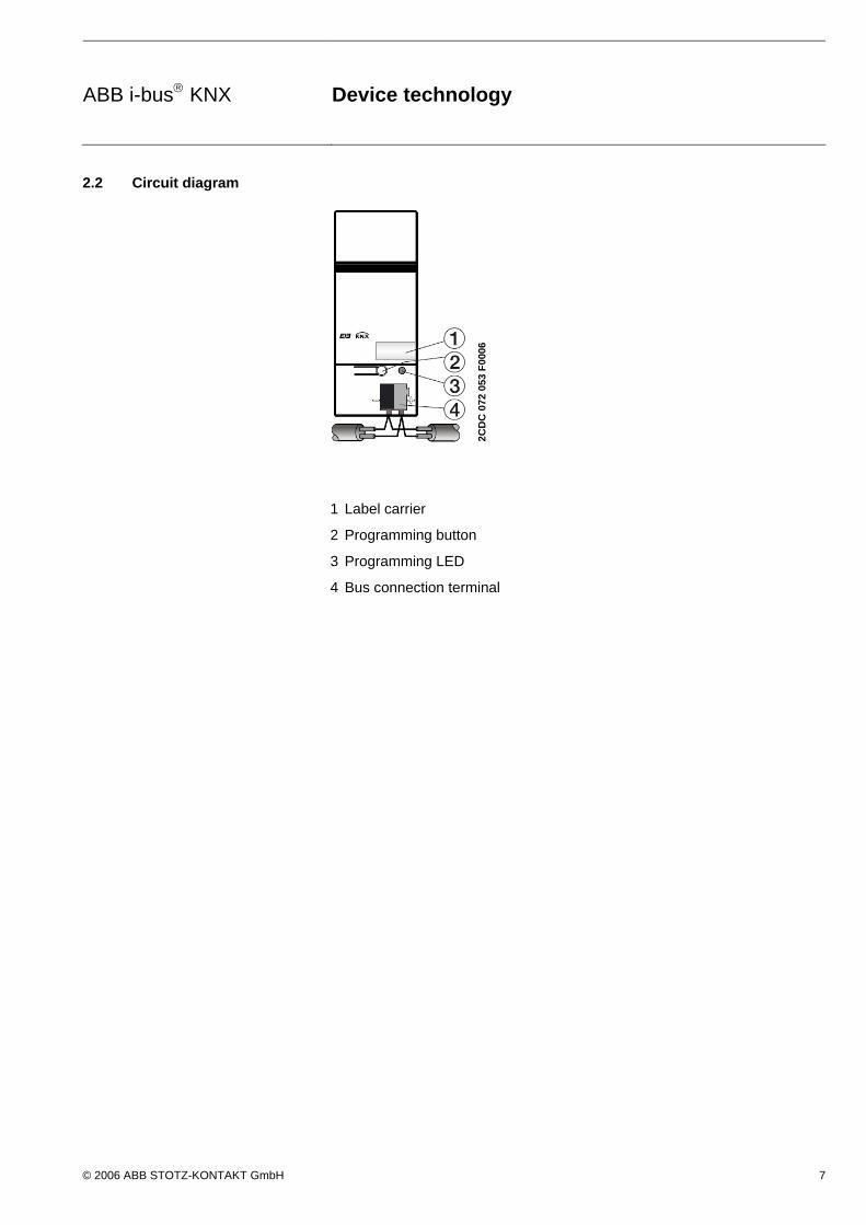
ABB i-bus KNX Device technology
© 2006 ABB STOTZ-KONTAKT GmbH 7
2.2 Circuit diagram
1 Label carrier
2 Programming button
3 Programming LED
4 Bus connection terminal
2CD
C 0
72 0
53 F
0006

ABB i-bus KNX Device technology
© 2006 ABB STOTZ-KONTAKT GmbH 8
2.3 Dimension drawing
2CD
C 0
72 0
51 F
0006
2C
DC
072
051
F00
06

ABB i-bus KNX Device technology
© 2006 ABB STOTZ-KONTAKT GmbH 9
2.4 Assembly and installation
The Data Logging Unit is a modular installation device for installation in the distribution board on 35 mm mounting rails to DIN EN 60 715.
The connection to the bus is implemented using the supplied bus connection terminal.
The device is ready for operation after connection to the bus voltage.
Accessibility of the devices for the purpose of operation, testing, visual inspection, maintenance and repair must be provided (compliant to DIN VDE 0100-520).
Commissioning requirements
In order to commission the Data Logging Unit, a PC with ETS and a connection to the ABB i-bus®, e.g. via an RS232 interface or a USB port is necessary.
The device is ready for operation after connection to the bus voltage.
The installation and commissioning may only be carried out by electrical specialists. The appropriate norms, guidelines, regulations and specifications should be observed when planning and setting up electrical installations.
The device should be protected from damp, dirt and damage during transport, storage and operation.
The device should not be operated outside the range of the specified technical data!
The device should only be operated in an enclosed housing (distribution board)!
Supplied state
The Data Logging Unit is supplied with the physical address 15.15.255. The application program is pre-installed. Hence, only group addresses and parameters must be loaded during commissioning. The entire application can be reloaded as required. A longer downtime may result if the application program is changed or after a discharge.
Assignment of the physical address
The assignment and programming of the physical addresses, group addresses and parameters is undertaken in the ETS.
Cleaning
If devices become dirty, they can be cleaned using a dry cloth. Should a dry cloth not remove the dirt, they can be cleaned using a slightly damp cloth and soap solution. Corrosive materials or solutions should never be used.
Maintenance
The device is maintenance-free. No repairs should be carried out by unauthorised personnel if damage occurs (e.g. during transport or storage). The warranty expires if the device is opened.


ABB i-bus KNX Commissioning
© 2006 ABB STOTZ-KONTAKT GmbH 11
3 Commissioning
3.1 Overview
For the Data Logging Unit BDB/S 1.1, a high-performance application program Data Logging/1 is available. Programming requires the KNX Software Tool (ETS). When ETS3 is used, the product files with the file extension *.VD3 must be imported.
Maximum number of communication objects 250
Maximum number of group addresses 254
Maximum number of associations 255
3.2 Parameters
This chapter describes the parameters of the BDB/S 1.1 using parameter windows. The parameter window features a dynamic structure so that further parameters, or even whole parameter windows may be enabled depending on the parameterisation and the function of the outputs.
The default values of the parameters are underlined, e.g.:
Option: yes no
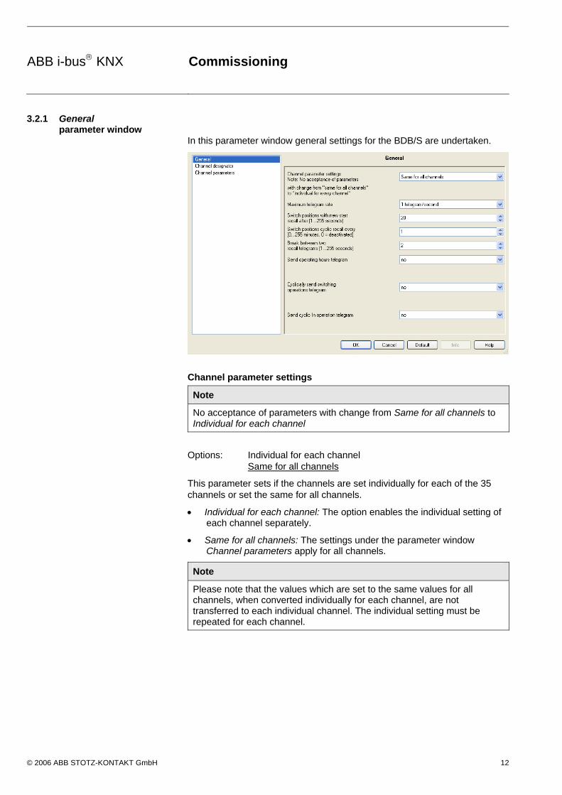
ABB i-bus KNX Commissioning
© 2006 ABB STOTZ-KONTAKT GmbH 12
3.2.1 General parameter window
In this parameter window general settings for the BDB/S are undertaken.
Channel parameter settings
Note
No acceptance of parameters with change from Same for all channels to Individual for each channel
Options: Individual for each channel Same for all channels
This parameter sets if the channels are set individually for each of the 35 channels or set the same for all channels.
Individual for each channel: The option enables the individual setting of each channel separately.
Same for all channels: The settings under the parameter window Channel parameters apply for all channels.
Note
Please note that the values which are set to the same values for all channels, when converted individually for each channel, are not transferred to each individual channel. The individual setting must be repeated for each channel.

ABB i-bus KNX Commissioning
© 2006 ABB STOTZ-KONTAKT GmbH 13
Maximum telegram rate
Options: 1/2/3/5/10/20 telegrams/second
To control the bus load, it is possible to limit the Maximum telegram rate per second with this parameter.
Example
With the setting 5 telegrams/second a maximum of 5 telegrams will be sent in a second.
Switch positions with new start recall after [1…255 seconds]
Options: 1…20…255 seconds
Using this parameter, the time interval is set at which the switch positions can be recalled on the monitored channels after a new start.
Example
If the Data Logging Unit is restarted and the setting is set to 2 seconds, after 2 seconds it will commence to recall all the switch positions of the parameterised channels.
Switch positions cyclic recall every [0…255 minutes, 0 = deactivated]
Options: 0…1…255 minutes 0 = function deactivated
The time interval is set after which the switch positions are recalled on a cyclic basis with this parameter.
Note
The set cycle time applies for all channels. The function can be enabled or inhibited for each channel.
If the switch positions are recalled cyclically, ensure that on the recalling device, e.g. a switch actuator channel, the R flag is set in the communication object to be recalled. Otherwise the Data Logging Unit cannot recall the switch position.
Break between two recall telegrams [1…255 seconds]
Options: 1…2…255 seconds
In order to allow co-ordinated recall of the individual switch positions, a pause is set between two recall telegrams.
Note
If a switch actuator channel does not respond, the telegram will be repeated twice.

ABB i-bus KNX Commissioning
© 2006 ABB STOTZ-KONTAKT GmbH 14
Send operating hours telegram
Options: no cyclically after a change
no: An operating hours telegram is not sent.
cyclically: Operating hours telegrams are sent cyclically.
after a change: Operating hours telegrams are sent after each change.
If the option cyclically is selected, the following parameters are displayed:
Cycle time [1…255 hours]
Options: 1…255 hours
The cycle time is thus set here. After this time all the operating hours telegrams are sent.
Cyclically send switching operations telegram
Options: no yes
no: A switching operations telegram is not sent.
yes: A switching operations telegram are sent cyclically.
If the option yes is selected, the following parameters are displayed:
Cycle time [1…255 hours]
Options: 1…255 hours
The cycle time is thus set here. After this time the switching operations telegrams are sent.
Send cyclic In operation telegram
Options: no yes
no: The cyclic In operation telegram is not sent.
yes: Cyclic In operation telegram is sent, additionally the communication object In operation – System appears.
If the option yes is selected, the following parameters are displayed:
Send interval for In operation telegram
Options: 10 min/30 min/1 h/3 h/6 h/12 h/24 h
The communication object In operation – System is sent cyclically on the bus after the set interval. The telegram value is always 1.
This can be used to monitor the Data Logging Unit.

ABB i-bus KNX Commissioning
© 2006 ABB STOTZ-KONTAKT GmbH 15
3.2.2 Parameter window Channel designator
In this parameter window the designations for the channels are entered.
Designation for channel X
Options: <Text>
With this parameter it is possible to enter a text of up to 40 characters in length for identification in the ETS.
Note
The text which is entered is used to offer help, in order to provide an overview of the channels when they are fully assigned and to indicate the function assigned to the channel. The text is purely for informative purposes and has no further function.

ABB i-bus KNX Commissioning
© 2006 ABB STOTZ-KONTAKT GmbH 16
3.2.3 Channel parameter settings Individual for each channel
If the option Individual for each channel is selected in the parameter Channel parameter settings in the parameter window General, on page 11, the following parameter window appears:
3.2.3.1 Parameter window Channel parameters
Channel selection
Options: Channel 1…Channel 35
With this parameter you define which channels are to be programmed.

ABB i-bus KNX Commissioning
© 2006 ABB STOTZ-KONTAKT GmbH 17
Cyclic switch position recall (only if cyclic recall greater than 0)
Options: no yes
no: do not recall switch position.
yes: recall switch position.
With this parameter recall of the switch position is activated.
Note
The cycle time for this purpose is set in the parameter Switch positions cyclic recall every [0…255 hours, 0 = deactivated] in the parameter window General.
If the switch positions are recalled cyclically, ensure that on the recalling device, e.g. a switch actuator channel, the R flag is set in the communication object to be recalled. Otherwise the Data Logging Unit cannot recall the switch position.
Counter/limit/start values can be changed via BUS
Options: no yes
no: Counter/limit/start values can not be changed via the bus.
yes: Counter/limit/start values can be changed via the bus.
Note
The communication objects Channel 1 operating hours start/limit value – Change/read and Channel 1 switching operations start/limit value – Change/read are always visible.
How can the counter/limit/start values be changed?
Before the counters, start and limit values can be changed, 1 must be received on the communications object Enable delete/overwrite - System.
If a 1 is received the enable to delete/overwrite of the operating data is issued and a time window of ten seconds is activated. The time window closes automatically ten seconds after the last change and the communications object value is reset to 0 and sent on the bus.
The time window remains active for at least ten seconds after the last close command.
What is the counter value?
The counter value signifies the current operating hours and switching operations in the Data Logging Unit.

ABB i-bus KNX Commissioning
© 2006 ABB STOTZ-KONTAKT GmbH 18
What is the limit value?
The limit value is only relevant when counting upwards. A limit value can be defined by a parameter. The limit value can also be modified via the bus. If the limit value is reached, the communication object Channel 1 operating hours - Alarm sends a 1.
Note
The communication objects Channel 1 operating hours start/limit value – Change/read and Channel 1 switching operations start/limit value – Change/read are always visible.
What is the start value?
The start value is only relevant when counting downwards. A start value can be defined by a parameter. The start value can also be modified via the bus. Counting down to zero starts at the start value. If the value 0 is reached, the communication object Channel 1 operating hours - Alarm sends a 1.
Note
The counter stops at zero.
Overwrite saved counter values with download
Options: no yes
no: saved counter values are not overwritten.
yes: saved counter values are overwritten, and the following parameters appear.
Note
The counter value can also be modified via the bus.
If the option yes is selected, the following parameters are displayed:
Hinweis
Both parameters are not displayed directly underneath as is generally the case, but rather each as the last parameter in the operating hours and switching operations areas.

ABB i-bus KNX Commissioning
© 2006 ABB STOTZ-KONTAKT GmbH 19
Operating hours new counter value after download
Options: 0…100,000
With this parameter a new counter value is set for the operating hours after download.
Note
If the operating hours are counting as a remaining run time (downwards counter), a plausibility test is undertaken.
Example
If a start value of 2,500 is set and the new counter value is set to 3,500, the new counter value is automatically corrected to 2,500, as the new counter value cannot be greater than the start value.
Switching operations new counter value after download
Options: 0…4,294,967,295
With this parameter a new counter value is set for the switching operations after download.
Note
If the operating hours are counting as a remaining run time (downwards counter), a plausibility test is undertaken.
Example
If a start value of 2,500 is set and the new counter value is set to 3,500, the new counter value is automatically corrected to 2,500, as the new counter value can not be greater than the start value.

ABB i-bus KNX Commissioning
© 2006 ABB STOTZ-KONTAKT GmbH 20
3.2.3.2 Parameters of Operating hours
Operating hours value range
This parameter serves as a note or remark.
The value range is between 0 and 100,000.
Count operating hours with switch position
Options: ON OFF ON and OFF (always)
With this parameter you set the switch state at which the operating hours are to be counted.
ON: counting is undertaken at a communication object value of 1, i.e. at a communication object value of 1 the operating hours counter is started and the counting stops at a value of 0.
OFF: counting is undertaken at a communication object value of 0, i.e. at a communication object value of 0 the operating hours counter is started and the counting stops at a value of 1.
ON and OFF (always): counting is undertaken at a communication object value of 0 and 1. After the Data Logging Unit is powered up the operating hours counter will run permanently.
Thus for example, the total connection time of equipment in the ABB i-bus® system can be measured.
Note
Internally the Data Logging Unit counts exactly to the second, the output of the operating hours telegram occurs for example at a full 60 minutes, 120 minutes etc.
Count operating hours with connection failure to channel
Options: Count Do not count Dependent on last switch position
Count: the operating hours continue to be counted.
Do not count: the operating hours are not counted, i.e., as soon as a connection is re-established to the channel counting will continue.
Dependent on last switch position: counting will continue or cease depending on the last communication object value.
Note
Connection failures can now only be determined on channels which are cyclically recalled, i.e. reaction only according to the options, otherwise counting continues.
How does counting continue?
It is dependent on the parameter setting at Count operating hours with switch position.

ABB i-bus KNX Commissioning
© 2006 ABB STOTZ-KONTAKT GmbH 21
Operating hours count method
Options: Total runtime Remaining runtime
Total runtime: counting upwards (incremental counter) beginning at 0.
Remaining runtime: counting downwards (decrementing counter) beginning at the start value.
Note
All details stated in hours.
If the option Total runtime is selected, the following parameters appear:
Operating hours limit value
Options: 0…1,000…100,000
The limit value for the operating hours is set with this parameter. If this value is reached the communication object Channel 1 operating hours - Alarm sends a 1.
Note
Thereafter counting will continue up to the end value of 100,000. The counter value stops at 100,000.
Overwrite operating hours limit value with download
Options: no yes
no: Operating hours limit value will not be overwritten.
yes: Operating hours limit value will be overwritten.
Note
Changes of the limit value via the bus with a download is not taken into consideration. The parameterised value is set as a limit value.

ABB i-bus KNX Commissioning
© 2006 ABB STOTZ-KONTAKT GmbH 22
Operating hours new counter value after download
Options: 0…100,000
With this parameter a new counter value is set for the operating hours after download.
Note
This parameter appears if the parameter Overwrite saved counter values with download has been programmed with yes.
If the operating hours are counting as a remaining run time (downwards counter), a plausibility test is undertaken.
Example
If a start value of 2,500 is set and the new counter value is set to 3,500, the new counter value is automatically corrected to 2,500, as the new counter value cannot be greater than the start value.
If the option Remaining runtime is selected, the following parameters appear:
Operating hours start value
Options: 0…1,000…100,000
The start value for the operating hours is set with this parameter. Counting down to zero starts at the start value. If the value 0 is reached the communication object Channel 1 operating hours - Alarm sends a 1.
Note
The counter stops at zero.
Overwrite operating hours start value with download
Options: no yes
no: Operating hours start value will not be overwritten.
yes: Operating hours start value will be overwritten.
Note
Changes of the start value via the bus with a download is not taken into consideration. The parameterised value is set as a start value.

ABB i-bus KNX Commissioning
© 2006 ABB STOTZ-KONTAKT GmbH 23
Operating hours new counter value after download
Options: 0…100,000
With this parameter a new counter value is set for the operating hours after download.
Note
This parameter appears if the parameter Overwrite saved counter values with download has been programmed with yes.
If the operating hours are counting as a remaining run time (downwards counter), a plausibility test is undertaken.
Example
If a start value of 2,500 is set and the new counter value is set to 3,500, the new counter value is automatically corrected to 2,500, as the new counter value cannot be greater than the start value.

ABB i-bus KNX Commissioning
© 2006 ABB STOTZ-KONTAKT GmbH 24
3.2.3.3 Parameters of Switching operations
Switching operations value range
This parameter serves as a note or remark.
The value range is between 0 and 4,294,967,295.
Count operations with change of switch position from
Options: ON -> OFF OFF -> ON
With this parameter the switch operations are defined.
ON -> OFF: A switch operation is counted if switching occurs from an ON telegram to an OFF telegram.
OFF -> ON: A switch operation is counted if switching occurs from an OFF telegram to an ON telegram.
Switching operations count method
Options: Total value Remaining value
Total value: Counting upwards beginning at 0.
Remaining value: Counting downwards beginning at the start value.
Note
A 1 = 1 switching operation.
If the option Total value is selected, the following two parameters appear:
Switching operations limit value
Options: 0…1,000…4,294,967,295
The limit value for the switching operations is set with this parameter. If this value is reached the communication object Channel 1 switching operations - Alarm sends a 1.
Note
Thereafter counting will continue up to the end value of 4,294,967,295. The counter value stops at 4,294,967,295.
Overwrite switching operations limit value with download
Options: no yes
no: Switching operations limit value will not be overwritten.
yes: Switching operations limit value will be overwritten.
Note
Changes of the limit value via the bus with a download are not taken into consideration. The parameterised value is set as a limit value.

ABB i-bus KNX Commissioning
© 2006 ABB STOTZ-KONTAKT GmbH 25
Switching operations new counter value after download
Options: 0…4,294,967,295
With this parameter a new counter value is set for the switching operations after download.
Note
This parameter appears if the parameter Overwrite saved counter values with download has been programmed with yes.
If the operating hours are counting as a remaining run time (downwards counter), a plausibility test is undertaken.
Example
If a start value of 2,500 is set and the new counter value is set to 3,500, the new counter value is automatically corrected to 2,500, as the new counter value can not be greater than the start value.
If the option Remaining value is selected, the following two parameters appear:
Switching operations start value
Options: 4,294,967,295…1,000…0
The start value for the switching operations is set with this parameter. Counting down to zero starts at the start value. If the value 0 is reached the communication object Channel 1 switching operations - Alarm sends a 1.
Note
The counter stops at zero.
Overwrite switching operations start value with download
Options: no yes
no: Switching operations start value will not be overwritten.
yes: = Switching operations start value will be overwritten.
Note
A change of the start value via the bus with a download is not taken into consideration. The parameterised value is set as a start value.

ABB i-bus KNX Commissioning
© 2006 ABB STOTZ-KONTAKT GmbH 26
Switching operations new counter value after download
Options: 0…4,294,967,295
With this parameter a new counter value is set for the switching operations after download.
Note
This parameter appears if the parameter Overwrite saved counter values with download has been programmed with yes.
If the operating hours are counting as a remaining run time (downwards counter), a plausibility test is undertaken.
Example
If a start value of 2,500 is set and the new counter value is set to 3,500, the new counter value is automatically corrected to 2,500, as the new counter value can not be greater than the start value.

ABB i-bus KNX Commissioning
© 2006 ABB STOTZ-KONTAKT GmbH 27
3.2.4 Channel parameter settings Same for all channels
If the option Same for all channels is selected in the parameter Channel parameter settings in the parameter window General, page 11, the following parameter window appears:
3.2.4.1 Parameter window Channel parameters
Channel selection
This parameter serves as a note or remark.
This indicates in the parameter window General in the parameter Channel parameter settings that the option Same for all channels has been selected.
Note
All further parameters can be taken from the description in the chapter channel parameter settings Individual for each channel, page 16.

ABB i-bus KNX Commissioning
© 2006 ABB STOTZ-KONTAKT GmbH 28
3.3 Communication objects
3.3.1 Channel 1
No. Function Object name Data type Flags
0 Received Channel 1 switch
position
EIS 1, 1 bit
DTP 1.001
C, W, T, U
Receives the current 1-bit switching telegram of the channel to be recorded, e.g. from
a switching actuator.
If the switch positions are recalled cyclically, ensure that on the recalling device, e.g. a switch
actuator channel, the R flag is set in the communication object to be recalled. Otherwise the
Data Logging Unit cannot recall the switch position.
1 Number Channel 1 operating
hours
EIS 11, 4 bytes
DTP 12.001
C, R, W, T
Contains the current number (= counter value) of operating hours.
With a bus voltage failure the current counter value is saved in the BDB/S.
Via the parameter Overwrite saved counter values with download and the option yes a further
parameter Operating hours new counter value after download opens
A new counter value can be defined with this.
The counter value can also be modified via the bus.
Before the current values can be changed, the communication object Enable delete/overwrite -
System must receive a 1.
With a change via the bus and the count method Remaining runtime the new operating hour's
value must be greater than 0 and less than the current start value. If an attempt is made via
the bus to set an operating hours (remaining runtime) value, which is greater than the start
value, it will be rejected and the enable for deleting and programming is discontinued. A 0 is
sent to the communication object Enable delete/overwrite - System.
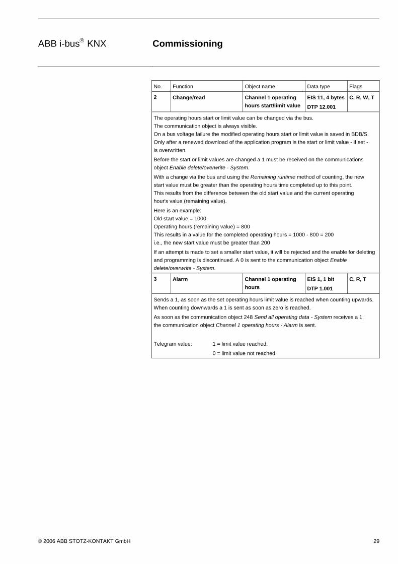
ABB i-bus KNX Commissioning
© 2006 ABB STOTZ-KONTAKT GmbH 29
No. Function Object name Data type Flags
2 Change/read Channel 1 operating
hours start/limit value
EIS 11, 4 bytes
DTP 12.001
C, R, W, T
The operating hours start or limit value can be changed via the bus.
The communication object is always visible.
On a bus voltage failure the modified operating hours start or limit value is saved in BDB/S.
Only after a renewed download of the application program is the start or limit value - if set -
is overwritten.
Before the start or limit values are changed a 1 must be received on the communications
object Enable delete/overwrite - System.
With a change via the bus and using the Remaining runtime method of counting, the new
start value must be greater than the operating hours time completed up to this point.
This results from the difference between the old start value and the current operating
hour's value (remaining value).
Here is an example:
Old start value = 1000
Operating hours (remaining value) = 800
This results in a value for the completed operating hours = 1000 - 800 = 200
i.e., the new start value must be greater than 200
If an attempt is made to set a smaller start value, it will be rejected and the enable for deleting
and programming is discontinued. A 0 is sent to the communication object Enable
delete/overwrite - System.
3 Alarm Channel 1 operating
hours
EIS 1, 1 bit
DTP 1.001
C, R, T
Sends a 1, as soon as the set operating hours limit value is reached when counting upwards.
When counting downwards a 1 is sent as soon as zero is reached.
As soon as the communication object 248 Send all operating data - System receives a 1,
the communication object Channel 1 operating hours - Alarm is sent.
Telegram value: 1 = limit value reached.
0 = limit value not reached.

ABB i-bus KNX Commissioning
© 2006 ABB STOTZ-KONTAKT GmbH 30
No. Function Object name Data type Flags
4 Number Channel 1 switching
operations
EIS 11, 4
bytes
DTP 12.001
C, R, W,
T
Contains the current number (= counter value) of switching operations
With a bus voltage failure the current counter value is saved in the BDB/S.
Via the parameter Overwrite saved counter values with download and the option yes,
a further parameter Switching operations new counter value after download opens.
A new counter value can be defined with this.
The counter value can also be modified via the bus.
Before the current values can be changed, the communication object Enable delete/overwrite -
System must receive a 1.
With a change via the bus and the count method Remaining runtime the new switching
operations value must be greater than 0 and less than the current start value. If an attempt
is made via the bus to set a switching operations value (remaining runtime) value, which is
greater than the start value, it will be rejected and the enable for deleting and programming
is discontinued. A 0 is sent to the communication object Enable delete/overwrite - System.
5 Change/read Channel 1 switching
operations start/limit
value
EIS 11, 4 bytes
DTP 12.001
C, R, W,
T
The switching operation start or limit value can be changed via the bus.
The communication object is always visible.
With bus voltage failure the modified switching operation start or limit value is saved.
Only after a renewed download of the application program is the start or limit value - if set -
overwritten.
Before the start or limit values are changed, a 1 must be received on the communications
object Enable delete/overwrite - System.
With a change via the bus and using the Remaining value method of counting; the new start
value must be greater than the detected switching operations completed up to now.
This results from the difference between the old start value and the current switching
operations value (remaining value).
Here is an example:
Old start value = 5000
Switching operations (remaining value) = 1200
This results in a value for the actually completed switching operations = 5000 - 1200 = 3800
i.e., the new start value must be greater than 3800.
If an attempt is made to set a smaller start value, it will be rejected and the enable for deleting
and programming is discontinued. A 0 is sent to the communication object Enable
delete/overwrite - System.
6 Alarm Channel 1 switching
operations
EIS 1, 1 bit
DTP 1.001
C, R, T
Sends a 1, as soon as the set switching operations limit value is reached when counting
upwards. When counting downwards a 1 is sent as soon as zero is reached.
As soon as the communication object 248 Send all operating data - System receives a 1,
the communication object Channel 1 switching operations - Alarm is sent.
Telegram value: 1 = limit value reached.
0 = limit value not reached.

ABB i-bus KNX Commissioning
© 2006 ABB STOTZ-KONTAKT GmbH 31
3.3.2 Channel 2…35
No. Function Object name Data type Flags
7…
13
See communication object
0…6
Channel 2
No. Function Object name Data type Flags
14…
20
See communication object
0…6
Channel 3
No. Function Object name Data type Flags
21…
27
See communication object
0…6
Channel 4
No. Function Object name Data type Flags
28…
34
See communication object
0…6
Channel 5
No. Function Object name Data type Flags
35…
41
See communication object
0…6
Channel 6
No. Function Object name Data type Flags
42…
48
See communication object
0…6
Channel 7
No. Function Object name Data type Flags
49…
55
See communication object
0…6
Channel 8
No. Function Object name Data type Flags
56…
62
See communication object
0…6
Channel 9
No. Function Object name Data type Flags
68…
74
See communication object
0…6
Channel 10
… etc. etc.

ABB i-bus KNX Commissioning
© 2006 ABB STOTZ-KONTAKT GmbH 32
3.3.3 General
No. Function Object name Data type Flags
245 Recall all switch positions System EIS 1, 1 bit
DTP 1.001
C, W
A recall of all switch positions of the monitored channels is started.
Telegram value: 1 = recall
0 = do not recall
Note
Channels are only recalled if:
- the input object of the channel is assigned to a group address.
- the channel parameter Cyclic switch position recall in the parameter window Channel parameters is set to yes.
Reason: Only channels that do not send a spontaneous message when their operating state is changed should be recalled. In order to avoid an unnecessary bus load you can set on the channel if the input object of the channel is recalled or not recalled. This applies both for cyclic recall as well as for recall via object 245. However, all channels are recalled during a new start irrespective of the channel parameter Cyclic switch position recall.
Reason: At a new start all channels must be recalled as otherwise the BDB/S will not be aware of the operating state and then will not be able to count the operating duration.
246 Send all operating data System EIS 1, 1 bit
DTP 1.001
C, W
Send the current operating data via the communication objects
Channel X switching operations - Number,
Channel X operating hours - Number
Channel X switching operations - Alarm and
Channel X operating hours - Alarm
Telegram value: 1 = send
0 = do not send

ABB i-bus KNX Commissioning
© 2006 ABB STOTZ-KONTAKT GmbH 33
No. Function Object name Data type Flags
247 Enable
delete/overwrite
System EIS1, 1 bit
DTP 1.001
C, W
If a 1 is received the enable to delete/overwrite of the operating data is issued and a time
window of ten seconds is activated. The time window closes automatically ten seconds after
the last change and the communications object value is reset to 0 and sent on the bus.
Via the communications object Delete all operating data - System, all operating data can be
deleted in the Data Logging Unit.
When counting upwards the counter value is set to zero.
When counting downwards the counter value is set to start value.
The operating hours counter, start and limit values, the switching operations counter, start
and limit values can be modified via the respective communication objects via the bus.
Telegram value: 1 = time window active
0 = time window not active
No. Function Object name Data type Flags
248 Delete all operating data System EIS 1, 1 bit
DTP 1.001
C, W
Deleting of the operating data switching operations and operating hours.
Deleting applies for all channels.
If a 1 is received the values of the communication objects
Channel X switching operations - Number and
Channel X operating hours - Number
are set to zero counting up and set to the start value when counting down.
Before the operating data is deleted a 1 must be received on the communications object
Enable delete/overwrite - System.
Telegram value: 1 = delete
0 = do not delete
249 In operation System EIS1, 1 bit
DTP 1.003
C, R, T
This communication object is only active if yes has been selected for the parameter Send
cyclic In operation telegram. As long as the communication object is activated it sends an
In operation telegram.
Telegram value: 1 = system in operation


ABB i-bus KNX Planning and application
© 2006 ABB STOTZ-KONTAKT GmbH 35
4 Planning and application
In this section you will find some tips for practical use of the Data Logging Unit.
4.1 Application fields
4.1.1 Application 1 This module can be used for example, in an office complex in order to record the operating life of fluorescent tubes.
For example when a reference office in the office complex is taken and from this data the switch on duration and switching operations are recorded.
Based on these values it is possible to determine what the service life of the fluorescent tubes will be. This will allow you to make assumption with regard to the maintenance expenditure and effort in the office complex.
4.1.2 Application 2 The module can be used for example in a functional building to record the switch on times of pumps in the heating system.
The service life of the pumps can be derived from the switch on time. This enables co-ordination of prompt pump maintenance.
4.1.3 Application 3 This module can be used for example in a department store to record the operating duration of the motors in the escalators.
A maintenance plan can be created based on the recorded use. The plan can be co-ordinated so that the operations in the department store are not affected.
4.1.4 Application 4 The module can be used for example in a hotel to record the operating life of filters in the air conditioning.
A maintenance plan can be created using this data.

ABB i-bus KNX Planning and application
© 2006 ABB STOTZ-KONTAKT GmbH 36
4.2 Reaction on bus voltage failure
With bus voltage failure the Data Logging Unit permanently saves the operating hours and switching operations.
4.3 Reaction on bus voltage recovery
Recall of the current counter states and update of the communication objects.

ABB i-bus KNX Appendix
© 2006 ABB STOTZ-KONTAKT GmbH 37
A Appendix
A.1 Scope of delivery
The Data Logging Unit is supplied with the following parts. Please check the items received using the following list.
1 pc. BDB/S 1.1 Data Logging Unit, MDRC
1 pc. installation and operating instructions
1 pc. bus connection terminal (red/black)
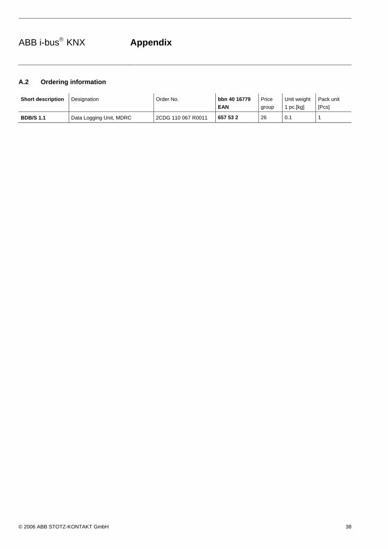
ABB i-bus KNX Appendix
© 2006 ABB STOTZ-KONTAKT GmbH 38
A.2 Ordering information
Short description Designation Order No. bbn 40 16779
EAN
Price
group
Unit weight
1 pc.[kg]
Pack unit
[Pcs]
BDB/S 1.1 Data Logging Unit, MDRC 2CDG 110 067 R0011 657 53 2 26 0.1 1

ABB i-bus KNX Appendix
© 2006 ABB STOTZ-KONTAKT GmbH 39
A.3 Notes

ABB i-bus KNX Appendix
© 2006 ABB STOTZ-KONTAKT GmbH 40
A.4 Notes


Pu
b. N
o. 2
CD
C 5
13
034
D0
202
ABB The technical details in this publication are subject to change without notice.
Your EIB- Partner
Your KNX-Partner
www.abb.com/knx