Embed Size (px)
Citation preview

Nominal heating capacity range 74 - 390 kW2 efficiency levels3 sound configurationFull packaged solutionPerformance according to EN14511
Refrigerant: R-32 HFC
Code CSS 10.21
Date December 2019
Product manual
EWYT-BAir Cooled Heat Pump with scroll compressors

GENERAL CHARACTERISTICS
Low operating cost.
The new Daikin BLUEVOLUTION Heat Pump series (EWYTB-) is the result of careful design aimed to optimize the energy efficiency and thus the total life cycle cost, with reduced operating cost thanks to outstanding performances and reliability. The Heat Pump feature high efficiency scroll compressor arranged in tandem or trio configuration on each refrigerant
circuit, optimized condensing section with advanced technology condensing fans and plates Water Side Heat Exchanger with low refrigerant content and reduced pressure drops. Low environmental impact. Latest revision of F-GAS, entered into force in 2015, set up a phase down program for traditional HFC’s refrigerants. In 2018 first significant reduction step will be introduced (37%) and in 2030 the reduction (calculated in equivalent
CO2 tons) will need to achieve almost 80%.
The new Daikin BLUEVOLUTION Heat Pump uses R-32 refrigerant to reduce drastically the carbon footprint of the unit. The selection of R-32 (chemical name difluoromethane) minimises the global warming impact of scroll compressor units thanks to the lower Global Warming Potential in combination with high-energy efficiency. The Global Warming Potential of R-32 is 675, which is only one third of the commonly used refrigerant R-410A. Thanks to the lower flammability classification (R-32 refrigerant is classified A2L in ISO817), it can be safely used in many applications including chilled water systems. Being a single component refrigerant, R-32 is also easier to recycle
and reuse, that is another environmental plus in its favour. Daikin has a long history of continuous reduction of the environmental impact of cooling, heating and refrigeration, having a unique expertise that comes from manufacturing both refrigerants and equipment. This position is one of the results of company's corporate philosophy to "Be a Company that Leads in Applying Environmentally Friendly Practices".
Regarding refrigerant choice, Daikin has expertise in using fluorinated (HFC, HFO) as well as non-fluorinated gases (ammonia, carbon dioxide, hydrocarbons), because the company believes in diversity of refrigerant choice to allow the best suited solution to be used in each application.
Range overview.
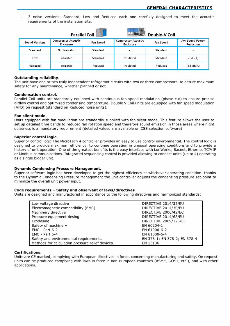
EWYTB- is available with: - 2 different layouts: Parallel Coil coil and Double V Coil.
- 2 Efficiency levels: Gold (high efficiency) and Silver (standard efficiency).
- One or Two independent refrigerant circuits.
GENERAL CHARACTERISTICS
- 3 noise versions: Standard, Low and Reduced each one carefully designed to meet the acoustic
requirements of the installation site.
Outstanding reliability. The unit have one or two truly independent refrigerant circuits with two or three compressors, to assure maximum safety for any maintenance, whether planned or not. Condensation control.
Parallel Coil units are standardly equipped with continuous fan speed modulation (phase cut) to ensure precise airflow control and optimized condensing temperature. Double V Coil units are equipped with fan speed modulation
(VFD) on request (standard on Reduced noise units). Fan silent mode. Units equipped with fan modulation are standardly supplied with fan silent mode. This feature allows the user to set up detailed time bands to reduced fan rotation speed and therefore sound emission in those areas where night
quietness is a mandatory requirement (detailed values are available on CSS selection software)
Superior control logic. Superior control logic The MicroTech 4 controller provides an easy to use control environmental. The control logic is designed to provide maximum efficiency, to continue operation in unusual operating conditions and to provide a history of unit operation. One of the greatest benefits is the easy interface with LonWorks, Bacnet, Ethernet TCP/IP or Modbus communications. Integrated sequencing control is provided allowing to connect units (up to 4) operating
as a single bigger unit.
Dynamic Condensing Pressure Management. Superior software logic has been developed to get the highest efficiency at whichever operating condition: thanks
to the Dynamic Condensing Pressure Management the unit controller adjusts the condensing pressure set-point to minimize the overall unit power input.
Code requirements – Safety and observant of laws/directives Units are designed and manufactured in accordance to the following directives and harmonized standards:
Low voltage directive DIRECTIVE 2014/35/EU
Electromagnetic compatibility (EMC) DIRECTIVE 2014/30/EU
Machinery directive DIRECTIVE 2006/42/EC
Pressure equipment desing DIRECTIVE 2014/68/EU
Ecodesing DIRECTIVE 2009/125/EC
Safety of machinery EN 60204-1
EMC - Part 6-2 EN 61000-6-2
EMC - Part 6-4 EN 61000-6-4
Safety and environmental requirements EN 378-1; EN 378-2; EN 378-4
Methods for calculation pressure relief devices. EN 13136
Certifications. Units are CE marked, complying with European directives in force, concerning manufacturing and safety. On request units can be produced complying with laws in force in non-European countries (ASME, GOST, etc.), and with other
applications.

GENERAL CHARACTERISTICS
Compressors Hermetic orbiting scroll type designed for R-32 operation and complete with motor over-temperature and over-current protection devices. Each compressor is equipped with an oil heater that keeps the oil from being diluted by
the refrigerant when the unit is not running. The compressors are connected in Tandem or Trio configuration on each refrigerant circuit. Each compressor is mounted on rubber antivibration mounts for a quite operation. Unit is delivered
with complete oil charge.
Water Side Heat Exchanger The unit is equipped with a direct expansion plate-to-plate type Heat Exchanger optimized for R-32 refrigerant operation. This heat exchanger is made of stainless-steel brazed plates and is covered with 20mm closed cell insulation material. The exchanger is equipped with an electric heater for protection against freezing and Heat
Exchanger water connections are provided with victaulic kit (as standard). The Water Side Heat Exchanger is manufactured in accordance to 2014/68/EU. The flow switch and the Water Side Heat Exchanger water filter are available as option (shipped loose). The installation of the flow switch and the water filter is mandatory. Air Side Heat Exchanger The Air Side Heat Exchanger is manufactured with internally enhanced seamless copper tubes arranged in a staggered row pattern and mechanically expanded into lanced and rippled aluminum Air Side Heat Exchanger fins
with full fin collars. An integral sub-cooler circuit provides sub-cooling to effectively eliminate liquid flashing and increase cooling capacity without increasing the power input.
Air Side Heat Exchanger fans Air Side Heat Exchanger fans are propeller type with high efficiency design blades to maximize performances. The blades are made of glass-reinforced resin and a guard protects each fan.
Parallel Coil units are equipped as standard with fan speed modulation (phase cut). Double V Coil units (standard and low sound versions) are equipped with on/off fans and inverter drive is available as an option. Double V Coil units reduced noise versions are equipped with inverter driven fans as standard. Electronic expansion valve The unit is equipped with electronic expansion valves to achieve precise control of R-32 refrigerant mass flow. As today’s systems require improved energy efficiency, accurate temperature control, wide range of operating
conditions, the application of electronic expansion valves becomes mandatory. Electronic expansion valve has unique features: short opening and closing time, high resolution, positive shut-off function to eliminate use of additional solenoid valve, continuous modulation of mass flow without stress in the refrigerant circuit and corrosion resistance stainless steel body. If compared to traditional thermostatic valves, electronic expansion valves allow the system to work with low Air Side Heat Exchanger pressure (winter time) without any refrigerant flow problems and the perfect control of the chilled water temperature.
Refrigerant circuit Each unit has one or two independent refrigerant circuits and each one includes:
• Compressor • Refrigerant • Water Side Heat Exchanger
• Air Side Heat Exchanger • Electronic expansion valve • 4 way valve • Sight glass with moisture indicator • Filter drier • Charging valves • High pressure switch
• High pressure transducers • Low pressure transducers • Oil pressure transducer • Suction temperature sensor
Electrical panel Power and control are in the main panel that is manufactured to ensure protection against all weather conditions.
The electrical panel is IP54 and (when opening the doors) internally protected against possible accidental contact with live parts. The main panel is fitted with a main switch interlocked door that shuts off power supply when opening.

GENERAL CHARACTERISTICS
MicroTech 4 controller
The new MicroTech 4 controller is installed as standard in all Daikin units. It gives the possibility to check the most relevant control parameters and modify unit set-points. A built-in display shows unit operating status. Additionally, temperatures and pressures of water, refrigerant and air, programmable
values, set-points can be accessed based on a preset list of user profiles. A sophisticated software with adaptive logic, selects the most energy efficient combination of compressors, EEXV and fans to keep stable operating conditions to maximize unit energy efficiency and reliability. MicroTech 4 protects critical components based on external signals from onboard sub-system (such as motor temperatures, refrigerant
and oil pressures and temperatures, correctness of phase sequence, pressure switches and freezing of heat exchanger). The input coming from high-pressure switches cuts all digital output from the controller in less than 50ms, as an additional security for the equipment. Fast program cycle (less than 200ms) for a precise monitoring of the system and sub-systems. Floating point calculations supported for increased accuracy in Pressure / Temperature conversions.
Control main features Control system has the following feature: Management of compressors and fans modulation; Control of cooling or heating leaving water temperatures; Management of cooling and heating capacities according to the load; Switch of operating modes in less than 1 minute;
Return reset (set point reset based on return water temperature); • Set point reset (optional); • Unit operation in partial failure condition; • Managed operations during critical conditions:
- High ambient temperature; - High thermal load; - Startup with high and low differential operating conditions;
- Startup with high entering water temperature in cooling mode; - Startup with low entering water temperature in heating mode;
• Optimized management of compressor load; • Optimized fan management according to condensing pressure; • General faults alarm relay; • Automatic re-start in case of power failure; • Rapid Restart to recover full load in the shortest possible time for Data Centre application;
• ICM Standard control for multiple units management; • Soft load (optimized management of the compressor load during the start-up); • Start at high cold heat exchanger water temperature;
• Visualization of: - cooling and heating entering/leaving water temperature of heat exchangers; - outdoor ambient temperature;
- condensing-evaporating temperature and pressure, suction and discharge superheat for - each circuit; - hours and starts counter for compressors and pumps; - status safety devices;
Control additional features • System upgrade with commercial SD cards;
• Save/Restore of configuration parameters with a commercial SD card; • Ethernet port for remote or local servicing using standard web browsers; • Daikin on Site connectivity for cloud based Safety device / logic for each refrigerant circuit The following devices / logics are available:
• high pressure (pressure switch);
• high pressure (transducer); • low pressure (transducer); • fans circuit breakers; • high compressor discharge temperature; • high motor winding temperature; • phase monitor;
• low pressure ratio; • high oil pressure drops; • low oil pressure; • no pressure changes at start. System security The following securities are available:

GENERAL CHARACTERISTICS
• phase monitor; • low ambient temperature lock-out; • freeze protection.
Regulation type
Proportional integral derivative regulation on the cold heat exchanger leaving water output probe. MicroTech 4 MicroTech 4 built-in terminal has the following features: • Liquid crystal display with white back lighting, supports Unicode fonts for multi-lingual;
• Key-pad consisting of 3 keys; • Push’n’roll control for an increased usability; • Flash memory to protect the data; • Password access to modify the setting; • Application security to prevent application tampering or hardware usability with third party applications; • Alarm history memory to allow an easy fault analysis.
Supervising systems (on request) MicroTech 4 remote communication MicroTech 4 can communicate to BMS (Building Management System) based on the most common protocols as: • ModbusRTU (Native); • LonWorks,
• BACnet BTP certified over IP and MS/TP (class 4) (Native); • Ethernet TCP/IP (Native).

GENERAL CHARACTERISTICS
Nomenclature

OPTIONS
Standard Options (supplied on basic units)
Double set point (opt. code 10 – provided as standard)
Possibility to pre-set two different chilled water temperature set points (cooling mode).
Evaporator Victaulic KIT (opt. code 20 – provided as standard) It includes the victaulic joint and the counter pipe fitted with victaulic groove to be welded with the plant pipes - Opt. incompatibility 21.
20mm Evaporator insulation (opt. code 29) The heat exchanger is fitted as standard with 20mm closed cell insulation material.
Evaporator electric heater (opt. code 57 – provided as standard)
Electronic expansion valve (opt. code 60 – provided as standard)
Ambient outside temperature sensor and set-point reset (opt. code 67 – provided as standard)
Setpoint Reset: The leaving water temperature set-point can be overwritten through an external 4- 20mA signal,
through the ambient temperature, or through the water temperature ΔT.
Hour run meter (opt. code 68 – provided as standard)
General fault contactor (opt. code 69 – provided as standard)
Alarm from external device (opt. code 70)
The unit controller is able to receive an external alarm signal. The user can decide whether this alarm signal will
stop the unit or not.
Main switch interlock door (opt. code 97 – provided as standard)
Master / Slave (opt. code 128 – provided as standard)
The EWYT~B features the new DAIKIN Master/ Slave (M/S) control. Once set which unit has the role of master, the other(s) will operate as slave(s) based on the inputs provided by the master. The units must be installed in parallel in the hydronic plant.
With Master/Slave control is possible to balance the working hours of the compressors enhancing reliability and extending the life of the system

OPTIONS
In order to operate in Master/Slave mode an additional probe (PT1000 or NTC10K) must be installed on the common line of the plant and connected to the master unit. The additional probe is not provided by the factory. Master/Slave can manage units selected with pump on board (fix speed pumps). Note: check valves must be installed at the outlet of each unit.
Master/Slave can also manage the start and stop of external pumps (not provided by factory). In this case, the power supply of external pumps is not provided by the unit.
Mechanical Options – On request Discharge line shut-off valve (opt. code 61– Double V Coil units only)
Installed on the common discharge pipe of the compressors to facilitate maintenance operation (one discharge valve per refrigerant circuit).
Suction line shut-off valve (opt. code 62– Double V Coil units only) Installed on the common suction pipe of the compressors to facilitate maintenance operation (one suction valve per refrigerant circuit).
Fans circuit breakers (opt. code 96) Opt. incompatibility 99
Safety devices that, added to the standard protection devices, protect fan motors against overload and
overcurrent.
Water filter (opt. code 115)
The water filter removes impurities from water by means of a fine physical barrier. It must be installed on the water pipe connceted to the heat exchanger inlet. The filter is shipped loose together with two victaulic joints and two counter pipes to be welded on the plants. NOTE: The installation of the filter is mandatory.
Partial Heat Recovery (opt. code 03A)
A plate to plate heat exchanger for each refrigerant circuit is installed in series to the Air Side Heat Exchanger coil. There is no switch nor solenoid valve in the circuit, thus compressor discharged refrigerant is always flowing through the heat recovery exchanger and hot water production is always available while the unit is providing cooling. During the operation in heat recover the Air Side Heat Exchanger coils provides the sub-cooling ensuring
the right amount of liquid at the inlet of the expansion valve. The unit controller manages the condensing temperature set point in order to maximize the cooling effect and amount of energy recovered. The amount of heat recovered is about the 15/20% (according to the operating conditions) of the total heat
rejection of the unit. The unit performs the control on the recovery circuit, based on the return water temperature to the unit. Heat recovery capability is subject to cooling load demand (if no cooling demand is present then no heat recovery is available) - Opt. incompatibility 134, 135, 136, 137, 120e, 120f, 120g, 120h,
120i, 120j, 120k, 120l.
Evaporator flange kit (opt. code 21) Opt. incompatibility 20
High pressure side manometers (opt. code 63)
Low pressure side manometers (opt. code 64)
Double pressure relief valve with diverter (opt. code 91)
Cu-Cu Condenser coil (opt. code 45)
To give better protection against corrosion by aggressive environments. Not available for parallel coil units - Opt. incompatibility 46, 49, 117.
Cu-Cu-Sn Condenser coil (opt. code 46)
To give better protection against corrosion in aggressive environments and by salty air. Not available for parallel coil units - Opt. incompatibility 45, 49, 117.
Blygold Coil Treatment (opt. code 117) - It is a Polyurethane coating impregnated with metallic pigment which provides a long lasting corrosion protection to Air Side Heat Exchanger fins coils; it is UV resistant, flexible,
heat conductive, chemical resistant to aggressive environments. Opt. incompatibility 45, 46, 49.

OPTIONS
Hydronic kits: • One centrifugal pump (Low lift) (opt. code 78)
• One centrifugal pump (high lift) (opt. code 79) • Two centrifugal pump (Low lift) (opt. code 80)
• Two centrifugal pump (high lift) (opt. code 81)
• One centrifugal pump (Low lift) + water tank (opt. code 134)
• One centrifugal pump (high lift) + water tank (opt. code 135)
• Two centrifugal pump (Low lift) + water tank (opt. code 136) • Two centrifugal pump (high lift) + water tank (opt. code 137)
Unit mounted hydronic kits are available with single and dual pumps. The Low lift kits provides an average available head of 100 kPa at unit standard conditions. The High lift kits provides an average available head of 200 kPa at unit standard conditions.
The kit is completed with pressure gauge, safety valve, drain valve. The motor pump is protected by a circuit breaker installed in control panel. Pump motors are insulation class F, IP55 protected and supplied by the unit with 400V/3ph/50Hz electric current. The kit is assembled and wired to the control panel. In case of unit equipped with hydronic kit on board selected to operate with glycol mixture, contact factory. Water buffer tank volume (if selected), depends on unit model size – detailed informations available on section “Options (technical data)” of this databook.For incompatibility refer to the table below:
Option Description Incompatibility
78 ONE CENTRIFUGAL PUMP (LOW LIFT) 79 80 81 134 135 136 137 120f 120g 120h 120i 120j 120k 120l
79 ONE CENTRIFUGAL PUMP (HIGH LIFT) 78 80 81 134 135 136 137 120e 120g 120h 120i 120j 120k 120l
80 TWO CENTRIFUGAL PUMP (LOW LIFT) 78 79 81 134 135 136 137 120e 120f 120h 120i 120j 120k 120l
81 TWO CENTRIFUGAL PUMP (HIGH LIFT) 78 79 80 134 135 136 137 120e 120f 120g 120i 120j 120k 120l
134 ONE CENTRIFUGAL PUMP (LOW LIFT) + TANK 03A 78 79 80 81 135 136 137 120e 120f 120g 120h 120j 120k 120l
135 ONE CENTRIFUGAL PUMP (HIGH LIFT) + TANK 03A 78 79 80 81 134 136 137 120e 120f 120g 120h 120i 120k 120l
136 TWO CENTRIFUGAL PUMP (LOW LIFT) + TANK 03A 78 79 80 81 134 135 137 120e 120f 120g 120h 120i 120j 120l
137 TWO CENTRIFUGAL PUMP (HIGH LIFT) + TANK 03A 78 79 80 81 134 135 136 120e 120f 120g 120h 120i 120j 120k
Refrigerant leak detection (opt. code 121 - Available only on units with compressors’ enclosure)
Automated permanent refrigerant leak detection system installed on board. The refrigerant sensors are installed within the compressor enclosures and are specifically calibrated for R-32 refrigerant. When leaks above a certain concentration are detected, the sensor provides a signal to the unit controller (a specific alarm is visualized on the unit microprocessor). The automatic shut down and pump down of refrigerant into the condensing section
occurs on the detection of refrigerant leakage. The alarm threshold that triggers automatic pump down upon detection of refrigerant is set to a maximum of 500ppm. Available only on units with compressors’ enclosure.
Electrical options – On request
Compressor thermal overload relays (opt. code 11 – Double V Coil units only) Available on Double V Coil units only. - Opt. incompatibility 95
Under over voltage control (opt. code 15) Electronic device that monitors and displays input voltage. It stops the unit in case of phase loss, wrong phase sequence, or voltage exceeding minimum and maximum allowed values.
Energy meter (opt. code 16) Device installed inside the control box that displays units’ electrical power parameters such as input line voltage and phase current, input active and reactive power, active and reactive energy. An integrated RS485 module
allows a Modbus communication to an external BMS.
Speedtrol (opt. code 42 – Double V Coil units only) - Opt. incompatibility 99-99a
Continuous fan speed regulation on the first fan (VFD driven) of each circuit. It allows unit operation down to
-18ºC (available for standard and low sound version).
Evaporator flow switch (opt. code 58)
Supplied separately to be wired and installed on the Water Side Heat Exchanger water piping (by the customer). The installation of the flow switch in mandatory. Compressors circuit breakers (opt. code 95)
Safety devices that include in a single device all safety functions otherwise provided by standard fuses and optional thermal relays, such as protection against overcurrent, overload, current unbalance - Opt. incompatibility 11

Fans speed regulation (opt. code 99 and 99a)
Fans speed regulation: continuous modulation of the fans’ speed for optimal condensation control at low ambient temperatures.
Fans silent mode: This feature allows the user to set up customized time bands to reduced fans’ speed rotation and therefore sound emission in those areas where quiet is a mandatory requirement during specific time of the
day (e.g. night operation).
Note: option 99 is standard on Parallel Coil units (phase cut). - Opt. incompatibility 42, 99a
Note: option 99a is standard on Double V Coil V units reduced sound (inverter). - Opt. incompatibility 42, 96, 99.
Ground fault relay (opt. code 102 – Double V Coil units only) To shut down the unit in case of a ground fault condition is detected.
Nordic kit (opt. 114) This option is offering enhanced drain pans and water discharge line, electric heaters on the pans protected by insulating material and additional covers for plugs at the back side of the electrical panel. Recommended for cold regions installations.
Inverter kit for pumps:
- INVERTER KIT FOR 1 CENTR PUMP LOW LIFT (opt. code 120e) - INVERTER KIT FOR 1 CENTR PUMP HIGH LIFT (opt. code 120f)
- INVERTER KIT FOR 2 CENTR PUMP LOW LIFT (opt. code 120g) - INVERTER KIT FOR 2 CENTR PUMP HIGH LIFT (opt. code 120h)
Check the Price List for the Options Inverter kit and Tank
the Inverter kit must be associated with the corresponding hydronic kit (opt. code 78/79/80/81). It is standardly not compatibile with kit pump + water tank. Contact factory to evaluate feasibility. For incompatibility refer to the table below:
Option Description Incompatibility
120E INVERTER KIT FOR 1 CENTR PUMP LOW LIFT 03A 120f 120g 120h 120i 120j 120k 120l 79 80 81 134 135 136 137
120F INVERTER KIT FOR 1 CENTR PUMP HIGH LIFT 03A120e 120g 120h 120i 120j 120k 120l 78 80 81 134 135 136 137
120G INVERTER KIT FOR 2 CENTR PUMP LOW LIFT 03A 120e 120f 120h 120i 120j 120k 120l 78 79 81 134 135 136 137
120H INVERTER KIT FOR 2 CENTR PUMP HIGH LIFT '03A120e 120f 120g 120i 120j 120k 120l 78 79 80 134 135 136 137
120I INV KIT 1 CENTR PUMP LOW LIFT AND TANK 03A 120e 120f 120g 120h 120j 120k 120l 78 79 80 81 135 136 137
120J INV KIT 1 CENTR PUMP HIGH LIFT AND TANK 03A 120e 120f 120g 120h 120i 120k 120l 78 79 80 81 134 136 137
120K INV KIT 2 CENTR PUMP LOW LIFT AND TANK 03A 120e 120f 120g 120h 120i 120j 120l 78 79 80 81 134 135 137
120L INV KIT 2 CENTR PUMP HIGH LIFT AND TANK 03A 120e 120f 120g 120h 120i 120j 120k 78 79 80 81 134 135 136
The inverter kit can be used for the following purposes:
- Adjusting the water flow rate during unit commissioning.
- Control the pump speed via external input from Building Management System (BMS)
For this application a 0-10V signal for the pump speed must be provided from the plant manager according to the specific control strategy of the plant. The water must be within the minimum and maximum value allowed for the unit (refer to the “Operating limit” chapter). The change in water flow rate must not be exceed more than 10% of the design water flow rate per minute.
- Set a “thermostat off” pump speed. Providing the unit with the inverter kit for the on-board pump is possible to manage two different water flow settings. A setting for water flow during the "Thermostat ON" mode
(when the unit is actually providing cooling to the plant), and a set for the “thermostat off” mode (when the
plant load is satisfied and the compressors are waiting to start). This feature allows to achieve energy saving on plant operating cost by reducing the speed of the pumps when the unit has reached the set point.
Daikin on site modem with antenna (opt. code 155)
Whenever LAN connection to the unit will not be available, connecting the unit to Daikin on Site will be possible
through a dedicated 3G M2M modem that can be ordered from Factory. When ordered, the modem will be installed
on the unit before leaving the Factory.
Heating only mode (opt. code 188)
Allowing the unit to operate in heating mode only. Cooling mode operation is not supported.

OPTIONS
Installation options – On request
Rubber anti vibration mounts (opt. code 75) - option incompatibility 77.
Shipped loos, rubbe mounts are to be positioned under the base frame of the unit during installation. Ideal to reduce the vibrations when the unit is floor mounted.
Spring anti vibration mounts (opt. code 77) - option incompatibility 75.
Shipped loos, spring mounts are to be positioned under the base frame of the unit during installation. Ideal for dampening vibrations for installation on roofs and metallic structures.
External tank without cabinet – 500 L (opt. code 83)
Inertial tank for chilled water storage - option incompatibility 84-87-88.
External tank without cabinet – 1000 L (opt. code 84)
Inertial tank for chilled water storage - option incompatibility 83-87-88.
External tank with cabinet – 500 L (opt. code 87) Inertial tank for chilled water storage with cabinet - option incompatibility 83-84-88.
External tank with cabinet – 1000 L (opt. code 88)
Inertial tank for chilled water storage with cabinet - option incompatibility 83-84-87.
Other options – On request
Container kit (opt. code 71) Specific solution designed to facilitate loading/unloading of the unit into the container and to reduce risk of damage. - option incompatibility 112.
Transport kit (opt. code 112) Specific solution that offers shocks’ absorption during unit transportation. - option incompatibility 71.

TECHNICAL SPECIFICATION
EWYT~B-SS
MODEL EWYT085B-
SSA1 EWYT105B-
SSA1 EWYT135B-
SSA1 EWYT175B-
SSA1 EWYT205B-
SSA2 EWYT215B-
SSA1
COOLING PERFORMANCE
Capacity - Cooling kW 75 98 120 153 189 193
Capacity control - Type STEP STEP STEP STEP STEP STEP
Capacity control - Minimum capacity
% 50 38 50 38 19 50
Unit power input - Cooling kW 28 36.6 44.8 57.9 71.4 72.3
EER 2.68 2.67 2.69 2.64 2.65 2.67
ESEER 0 0 0 0 0 0
IPLV 4.43 4.4 4.32 4.28 4.33 4.36
CASING
Colour * IW IW IW IW IW IW
Material * GPSS GPSS GPSS GPSS GPSS GPSS
DIMENSIONS
Height mm 1800 1800 1800 1800 1800 1800
Width mm 1195 1195 1195 1195 1195 1195
Length mm 2225 2825 3425 3425 4350 4025
WEIGHT
Unit Weight kg 955 1065 1165 1320 1500 1500
Operating Weight kg 962 1072 1172 1327 1511 1511
WATER HEAT EXCHANGER
Type * PHE PHE PHE PHE PHE PHE
Fluid Water Water Water Water Water Water
Fouling Factor m2°C/W 0 0 0 0 0 0
Water Volume l 7 7 7 7 11 11
Water temperature in °C 12 12 12 12 12 12
Water temperature out °C 7 7 7 7 7 7
Water flow rate l/s 3.6 4.7 5.8 7.3 9 9.2
Water pressure drop kPa 14.9 24.1 35.1 54 45 46.4
Insulation material * Closed Cell Closed Cell Closed Cell Closed Cell Closed Cell Closed Cell
AIR HEAT EXCHANGER
Type * HFP HFP HFP HFP HFP HFP
FAN
Type * DPT DPT DPT DPT DPT DPT
Drive * VFD VFD VFD VFD VFD VFD
Diameter mm 450 450 450 450 450 450
Nominal air flow l/s 6888 10809 14412 13777 17220 17221
Air Temperature °C 35 35 35 35 35 35
Quantity No. 4 6 8 8 10 10
Speed rpm 1360 1360 1360 1360 1360 1360
Motor input kW 1.8 2.8 3.7 3.7 4.6 4.6
COMPRESSOR
Type Scroll Scroll Scroll Scroll Scroll Scroll
Oil charge l 6.5 7.69 8.88 10.7 15.3 12.6
Quantity No. 2 2 2 2 4 2
SOUND LEVEL**
Sound Power - Cooling dB(A) 84 87 89 91 90 92
Sound Pressure level@1m distance - Cooling
dB(A) 66 69 71 73 71 74
REFRIGERANT CIRCUIT
Refrigerant type R32 R32 R32 R32 R32 R32
Refrigerant charge kg 11 19 27 27 35 35
N. of circuits No. 1 1 1 1 2 1
PIPING CONNECTIONS
Evaporator water inlet/outlet mm 88.9 88.9 88.9 88.9 88.9 88.9

TECHNICAL SPECIFICATION
MODEL EWYT235B-
SSA2 EWYT255B-
SSA2 EWYT300B-
SSA2 EWYT340B-
SSA2 EWYT390B-
SSA2
COOLING PERFORMANCE
Capacity - Cooling kW 212 230 270 317 350
Capacity control - Type STEP STEP STEP STEP STEP
Capacity control - Minimum capacity
% 17 25 22 19 17
Unit power input - Cooling kW 78.9 86.5 102 117 132
EER 2.69 2.66 2.65 2.69 2.63
ESEER 0 0 0 0 0
IPLV 4.31 4.35 4.2 4.31 4.2
CASING
Colour * IW IW IW IW IW
Material * GPSS GPSS GPSS GPSS GPSS
DIMENSIONS
Height mm 1800 1800 2514 2514 2514
Width mm 1195 1195 2282 2282 2282
Length mm 4950 4950 3225 3225 4125
WEIGHT
Unit Weight kg 1800 1825 2100 2250 3180
Operating Weight kg 1811 1839 2114 2270 3200
WATER HEAT EXCHANGER
Type * PHE PHE PHE PHE PHE
Fluid Water Water Water Water Water
Fouling Factor m2°C/W 0 0 0 0 0
Water Volume l 11 14 14 20 20
Water temperature in °C 12 12 12 12 12
Water temperature out °C 7 7 7 7 7
Water flow rate l/s 10.1 11 12.9 15.1 16.7
Water pressure drop kPa 55.1 45.1 60.2 49.2 58.8
Insulation material * Closed Cell Closed Cell Closed Cell Closed Cell Closed Cell
AIR HEAT EXCHANGER
Type * HFP HFP HFP HFP HFP
FAN
Type * DPT DPT DPT DPT DPT
Drive * VFD VFD On/Off On/Off On/Off
Diameter mm 450 450 800 800 800
Nominal air flow l/s 20664 20664 28003 33604 46854
Air Temperature °C 35 35 35 35 35
Quantity No. 12 12 5 6 8
Speed rpm 1360 1360 900 900 900
Motor input kW 5.5 5.5 8.7 10.4 13.9
COMPRESSOR
Type Scroll Scroll Scroll Scroll Scroll
Oil charge l 16.5 17.7 19.6 21.4 23.3
Quantity No. 4 4 4 4 4
SOUND LEVEL**
Sound Power - Cooling dB(A) 91 92 94 95 96
Sound Pressure level@1m distance - Cooling
dB(A) 72 73 74 75 76
REFRIGERANT CIRCUIT
Refrigerant type R32 R32 R32 R32 R32
Refrigerant charge kg 43 43 27.5 42 71
N. of circuits No. 2 2 2 2 2
PIPING CONNECTIONS
Evaporator water inlet/outlet mm 88.9 88.9 88.9 88.9 88.9

TECHNICAL SPECIFICATION
EWYT~B-SL
MODEL EWYT085B-
SLA1 EWYT105B-
SLA1 EWYT135B-
SLA1 EWYT175B-
SLA1 EWYT205B-
SLA2 EWYT215B-
SLA1
COOLING PERFORMANCE
Capacity - Cooling kW 75 98 120 153 189 193
Capacity control - Type STEP STEP STEP STEP STEP STEP
Capacity control - Minimum capacity
% 50 38 50 38 19 50
Unit power input - Cooling kW 28 36.6 44.8 57.9 71.4 72.3
EER 2.68 2.67 2.69 2.64 2.65 2.67
ESEER 0 0 0 0 0 0
IPLV 4.43 4.4 4.32 4.28 4.33 4.36
CASING
Colour * IW IW IW IW IW IW
Material * GPSS GPSS GPSS GPSS GPSS GPSS
DIMENSIONS
Height mm 1800 1800 1800 1800 1800 1800
Width mm 1195 1195 1195 1195 1195 1195
Length mm 2225 2825 3425 3425 4350 4025
WEIGHT
Unit Weight kg 985 1095 1195 1350 1530 1530
Operating Weight kg 992 1102 1202 1357 1541 1541
WATER HEAT EXCHANGER
Type * PHE PHE PHE PHE PHE PHE
Fluid Water Water Water Water Water Water
Fouling Factor m2°C/W 0 0 0 0 0 0
Water Volume l 7 7 7 7 11 11
Water temperature in °C 12 12 12 12 12 12
Water temperature out °C 7 7 7 7 7 7
Water flow rate l/s 3.6 4.7 5.8 7.3 9 9.2
Water pressure drop kPa 14.9 24.1 35.1 54 45 46.4
Insulation material * Closed Cell Closed Cell Closed Cell Closed Cell Closed Cell Closed Cell
AIR HEAT EXCHANGER
Type * HFP HFP HFP HFP HFP HFP
FAN
Type * DPT DPT DPT DPT DPT DPT
Drive * VFD VFD VFD VFD VFD VFD
Diameter mm 450 450 450 450 450 450
Nominal air flow l/s 6888 10809 14412 13777 17220 17221
Air Temperature °C 35 35 35 35 35 35
Quantity No. 4 6 8 8 10 10
Speed rpm 1360 1360 1360 1360 1360 1360
Motor input kW 1.8 2.7 3.7 3.7 4.6 4.6
COMPRESSOR
Type Scroll Scroll Scroll Scroll Scroll Scroll
Oil charge l 6.5 7.69 8.88 10.7 15.3 12.6
Quantity No. 2 2 2 2 4 2
SOUND LEVEL**
Sound Power - Cooling dB(A) 83 85 87 88 88 89
Sound Pressure level@1m distance - Cooling
dB(A) 65 67 69 70 69 70
REFRIGERANT CIRCUIT
Refrigerant type R32 R32 R32 R32 R32 R32
Refrigerant charge kg 11 19 27 27 35 35
N. of circuits No. 1 1 1 1 2 1
PIPING CONNECTIONS
Evaporator water inlet/outlet mm 88.9 88.9 88.9 88.9 88.9 88.9

TECHNICAL SPECIFICATION TECHNICAL SPECIFICATION
MODEL EWYT235B-
SLA2 EWYT255B-
SLA2 EWYT300B-
SLA2 EWYT340B-
SLA2 EWYT390B-
SLA2
COOLING PERFORMANCE
Capacity - Cooling kW 212 230 270 317 350
Capacity control - Type STEP STEP STEP STEP STEP
Capacity control - Minimum capacity
% 17 25 22 19 17
Unit power input - Cooling kW 78.9 86.5 102 117 132
EER 2.69 2.66 2.65 2.69 2.63
ESEER 0 0 0 0 0
IPLV 4.31 4.35 4.2 4.31 4.2
CASING
Colour * IW IW IW IW IW
Material * GPSS GPSS GPSS GPSS GPSS
DIMENSIONS
Height mm 1800 1800 2514 2514 2514
Width mm 1195 1195 2282 2282 2282
Length mm 4950 4950 3225 3225 4125
WEIGHT
Unit Weight kg 1830 1855 2260 2410 3340
Operating Weight kg 1841 1869 2274 2430 3360
WATER HEAT EXCHANGER
Type * PHE PHE PHE PHE PHE
Fluid Water Water Water Water Water
Fouling Factor m2°C/W 0 0 0 0 0
Water Volume l 11 14 14 20 20
Water temperature in °C 12 12 12 12 12
Water temperature out °C 7 7 7 7 7
Water flow rate l/s 10.1 11 12.9 15.1 16.7
Water pressure drop kPa 55.1 45.1 60.2 49.2 58.8
Insulation material * Closed Cell Closed Cell Closed Cell Closed Cell Closed Cell
AIR HEAT EXCHANGER
Type * HFP HFP HFP HFP HFP
FAN
Type * DPT DPT DPT DPT DPT
Drive * VFD VFD On/Off On/Off On/Off
Diameter mm 450 450 800 800 800
Nominal air flow l/s 20664 20664 28003 33604 46854
Air Temperature °C 35 35 35 35 35
Quantity No. 12 12 5 6 8
Speed rpm 1360 1360 900 900 900
Motor input kW 5.5 5.5 8.7 10.4 13.9
COMPRESSOR
Type Scroll Scroll Scroll Scroll Scroll
Oil charge l 16.5 17.7 19.6 21.4 23.3
Quantity No. 4 4 4 4 4
SOUND LEVEL**
Sound Power - Cooling dB(A) 89 89 91 92 93
Sound Pressure level@1m distance - Cooling
dB(A) 70 70 71 72 73
REFRIGERANT CIRCUIT
Refrigerant type R32 R32 R32 R32 R32
Refrigerant charge kg 43 43 27.5 42 71
N. of circuits No. 2 2 2 2 2
PIPING CONNECTIONS
Evaporator water inlet/outlet mm 88.9 88.9 88.9 88.9 88.9

TECHNICAL SPECIFICATION
EWYT~B-SR
MODEL EWYT085B-SRA1
EWYT105B-SRA1
EWYT135B-SRA1
EWYT175B-SRA1
EWYT205B-SRA2
EWYT215B-SRA1
COOLING PERFORMANCE
Capacity - Cooling kW 74 96 119 150 186 189
Capacity control - Type STEP STEP STEP STEP STEP STEP
Capacity control - Minimum capacity
% 50 38 50 38 19 50
Unit power input - Cooling kW 28.7 37.4 45.5 59.5 73.2 74.3
EER 2.56 2.58 2.61 2.53 2.54 2.55
ESEER 0 0 0 0 0 0
IPLV 4.36 4.24 4.3 4.38 4.29 4.29
CASING
Colour * IW IW IW IW IW IW
Material * GPSS GPSS GPSS GPSS GPSS GPSS
DIMENSIONS
Height mm 1800 1800 1800 1800 1800 1800
Width mm 1195 1195 1195 1195 1195 1195
Length mm 2225 2825 3425 3425 4350 4025
WEIGHT
Unit Weight kg 985 1095 1195 1350 1530 1530
Operating Weight kg 992 1102 1202 1357 1541 1541
WATER HEAT EXCHANGER
Type * PHE PHE PHE PHE PHE PHE
Fluid Water Water Water Water Water Water
Fouling Factor m2°C/W 0 0 0 0 0 0
Water Volume l 7 7 7 7 11 11
Water temperature in °C 12 12 12 12 12 12
Water temperature out °C 7 7 7 7 7 7
Water flow rate l/s 3.5 4.6 5.7 7.2 8.9 9
Water pressure drop kPa 14.4 23.4 34.2 52.2 43.5 44.8
Insulation material * Closed Cell Closed Cell Closed Cell Closed Cell Closed Cell Closed Cell
AIR HEAT EXCHANGER
Type * HFP HFP HFP HFP HFP HFP
FAN
Type * DPT DPT DPT DPT DPT DPT
Drive * VFD VFD VFD VFD VFD VFD
Diameter mm 450 450 450 450 450 450
Nominal air flow l/s 6026 9483 12644 12052 15064 15065
Air Temperature °C 35 35 35 35 35 35
Quantity No. 4 6 8 8 10 10
Speed rpm 1200 1200 1200 1200 1200 1200
Motor input kW 1.7 2.5 3.4 3.4 4.2 4.2
COMPRESSOR
Type Scroll Scroll Scroll Scroll Scroll Scroll
Oil charge l 6.5 7.69 8.88 10.7 15.3 12.6
Quantity No. 2 2 2 2 4 2
SOUND LEVEL**
Sound Power - Cooling dB(A) 78 82 84 85 84 87
Sound Pressure level@1m distance - Cooling
dB(A) 60 64 65 67 66 68
REFRIGERANT CIRCUIT
Refrigerant type R32 R32 R32 R32 R32 R32
Refrigerant charge kg 11 19 27 27 35 35
N. of circuits No. 1 1 1 1 2 1
PIPING CONNECTIONS
Evaporator water inlet/outlet mm 88.9 88.9 88.9 88.9 88.9 88.9

TECHNICAL SPECIFICATION
MODEL EWYT235B-
SRA2 EWYT255B-
SRA2 EWYT300B-
SRA2 EWYT340B-
SRA2 EWYT390B-
SRA2
COOLING PERFORMANCE
Capacity - Cooling kW 209 226 265 311 344
Capacity control - Type STEP STEP STEP STEP STEP
Capacity control - Minimum capacity
% 17 25 22 19 17
Unit power input - Cooling kW 80.7 88.8 102 117 131
EER 2.59 2.55 2.6 2.65 2.61
ESEER 0 0 0 0 0
IPLV 4.28 4.26 4.29 4.69 4.58
CASING
Colour * IW IW IW IW IW
Material * GPSS GPSS GPSS GPSS GPSS
DIMENSIONS
Height mm 1800 1800 2514 2514 2514
Width mm 1195 1195 2282 2282 2282
Length mm 4950 4950 3225 3225 4125
WEIGHT
Unit Weight kg 1830 1855 2260 2410 3340
Operating Weight kg 1841 1869 2274 2430 3360
WATER HEAT EXCHANGER
Type * PHE PHE PHE PHE PHE
Fluid Water Water Water Water Water
Fouling Factor m2°C/W 0 0 0 0 0
Water Volume l 11 14 14 20 20
Water temperature in °C 12 12 12 12 12
Water temperature out °C 7 7 7 7 7
Water flow rate l/s 10 10.8 12.7 14.8 16.4
Water pressure drop kPa 53.5 43.6 58.1 47.6 57
Insulation material * Closed Cell Closed Cell Closed Cell Closed Cell Closed Cell
AIR HEAT EXCHANGER
Type * HFP HFP HFP HFP HFP
FAN
Type * DPT DPT DPT DPT DPT
Drive * VFD VFD VFD VFD VFD
Diameter mm 450 450 800 800 800
Nominal air flow l/s 18078 18078 23608 28330 39446
Air Temperature °C 35 35 35 35 35
Quantity No. 12 12 5 6 8
Speed rpm 1200 1200 780 780 780
Motor input kW 5 5 5.5 6.6 8.7
COMPRESSOR
Type Scroll Scroll Scroll Scroll Scroll
Oil charge l 16.5 17.7 19.6 21.4 23.3
Quantity No. 4 4 4 4 4
SOUND LEVEL**
Sound Power - Cooling dB(A) 86 86 87 88 89
Sound Pressure level@1m distance - Cooling
dB(A) 67 67 68 68 69
REFRIGERANT CIRCUIT
Refrigerant type R32 R32 R32 R32 R32
Refrigerant charge kg 43 43 27.5 42 71
N. of circuits No. 2 2 2 2 2
PIPING CONNECTIONS
Evaporator water inlet/outlet mm 88.9 88.9 88.9 88.9 88.9
TECHNICAL SPECIFICATION TECHNICAL SPECIFICATION
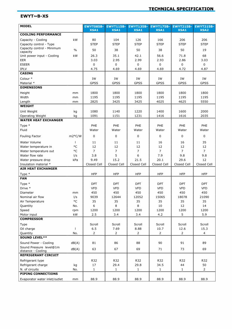
EWYT~B-XS
MODEL EWYT085B-
XSA1 EWYT115B-
XSA1 EWYT135B-
XSA1 EWYT175B-
XSA1 EWYT215B-
XSA1 EWYT215B-
XSA2
COOLING PERFORMANCE
Capacity - Cooling kW 80 104 126 166 206 206
Capacity control - Type STEP STEP STEP STEP STEP STEP
Capacity control - Minimum capacity
% 50 38 50 38 50 19
Unit power input - Cooling kW 26.3 35.1 42.1 56.6 71.8 68
EER 3.03 2.95 2.99 2.93 2.86 3.03
ESEER 0 0 0 0 0 0
IPLV 4.75 4.69 4.69 4.69 4.72 4.87
CASING
Colour * IW IW IW IW IW IW
Material * GPSS GPSS GPSS GPSS GPSS GPSS
DIMENSIONS
Height mm 1800 1800 1800 1800 1800 1800
Width mm 1195 1195 1195 1195 1195 1195
Length mm 2825 3425 3425 4025 4625 5550
WEIGHT
Unit Weight kg 1080 1140 1220 1400 1600 2000
Operating Weight kg 1091 1151 1231 1416 1616 2035
WATER HEAT EXCHANGER
Type * PHE PHE PHE PHE PHE PHE
Fluid Water Water Water Water Water Water
Fouling Factor m2°C/W 0 0 0 0 0 0
Water Volume l 11 11 11 16 16 35
Water temperature in °C 12 12 12 12 12 12
Water temperature out °C 7 7 7 7 7 7
Water flow rate l/s 3.8 5 6 7.9 9.8 9.8
Water pressure drop kPa 9.49 15.2 21.5 20.1 29.6 12
Insulation material * Closed Cell Closed Cell Closed Cell Closed Cell Closed Cell Closed Cell
AIR HEAT EXCHANGER
Type * HFP HFP HFP HFP HFP HFP
FAN
Type * DPT DPT DPT DPT DPT DPT
Drive * VFD VFD VFD VFD VFD VFD
Diameter mm 450 450 450 450 450 450
Nominal air flow l/s 9039 12644 12052 15065 18078 21090
Air Temperature °C 35 35 35 35 35 35
Quantity No. 6 8 8 10 12 14
Speed rpm 1200 1200 1200 1200 1200 1200
Motor input kW 2.5 3.4 3.4 4.2 5 5.9
COMPRESSOR
Type Scroll Scroll Scroll Scroll Scroll Scroll
Oil charge l 6.5 7.69 8.88 10.7 12.6 15.3
Quantity No. 2 2 2 2 2 4
SOUND LEVEL**
Sound Power - Cooling dB(A) 81 86 88 90 91 89
Sound Pressure level@1m distance - Cooling
dB(A) 63 67 69 71 73 69
REFRIGERANT CIRCUIT
Refrigerant type R32 R32 R32 R32 R32 R32
Refrigerant charge kg 17 29.4 29.8 34.5 44 50
N. of circuits No. 1 1 1 1 1 2
PIPING CONNECTIONS
Evaporator water inlet/outlet mm 88.9 88.9 88.9 88.9 88.9 88.9

TECHNICAL SPECIFICATION
MODEL EWYT235B-XSA2
EWYT265B-XSA2
EWYT310B-XSA2
EWYT350B-XSA2
COOLING PERFORMANCE
Capacity - Cooling kW 229 250 294 335
Capacity control - Type STEP STEP STEP STEP
Capacity control - Minimum capacity % 17 25 22 19
Unit power input - Cooling kW 74.9 83.4 95.9 109
EER 3.06 3 3.06 3.05
ESEER 0 0 0 0
IPLV 4.87 4.64 4.92 4.97
CASING
Colour * IW IW IW IW
Material * GPSS GPSS GPSS GPSS
DIMENSIONS
Height mm 1800 1800 2514 2514
Width mm 1195 1195 2282 2282
Length mm 6150 6150 4125 4125
WEIGHT
Unit Weight kg 2300 2350 2830 3080
Operating Weight kg 2335 2385 2865 3115
WATER HEAT EXCHANGER
Type * PHE PHE PHE PHE
Fluid Water Water Water Water
Fouling Factor m2°C/W 0 0 0 0
Water Volume l 35 35 35 35
Water temperature in °C 12 12 12 12
Water temperature out °C 7 7 7 7
Water flow rate l/s 10.9 11.9 14 16
Water pressure drop kPa 14.6 17.1 22.8 28.9
Insulation material * Closed Cell Closed Cell Closed Cell Closed Cell
AIR HEAT EXCHANGER
Type * HFP HFP HFP HFP
FAN
Type * DPT DPT DPT DPT
Drive * VFD VFD On/Off On/Off
Diameter mm 450 450 800 800
Nominal air flow l/s 24104 24104 29593 33820
Air Temperature °C 35 35 35 35
Quantity No. 16 16 7 8
Speed rpm 1200 1200 700 700
Motor input kW 6.7 6.7 6 6.9
COMPRESSOR
Type Scroll Scroll Scroll Scroll
Oil charge l 16.5 17.7 19.6 21.4
Quantity No. 4 4 4 4
SOUND LEVEL**
Sound Power - Cooling dB(A) 90 91 92 93
Sound Pressure level@1m distance - Cooling
dB(A) 70 71 72 73
REFRIGERANT CIRCUIT
Refrigerant type R32 R32 R32 R32
Refrigerant charge kg 50 55 70 70
N. of circuits No. 2 2 2 2
PIPING CONNECTIONS
Evaporator water inlet/outlet mm 88.9 88.9 88.9 88.9

TECHNICAL SPECIFICATION
EWYT~B-XL MODEL EWYT085B-
XLA1 EWYT085B-
XRA1 EWYT115B-
XLA1 EWYT135B-
XLA1 EWYT175B-
XLA1 EWYT215B-
XLA1
COOLING PERFORMANCE
Capacity - Cooling kW 80 79 104 126 166 206
Capacity control - Type STEP STEP STEP STEP STEP STEP
Capacity control - Minimum capacity
% 50 50 38 50 38 50
Unit power input - Cooling kW 26.3 26.6 35.1 42.1 56.6 71.8
EER 3.03 2.98 2.95 2.99 2.93 2.86
ESEER 0 0 0 0 0 0
IPLV 4.75 4.73 4.69 4.69 4.69 4.72
CASING
Colour * IW IW IW IW IW IW
Material * GPSS GPSS GPSS GPSS GPSS GPSS
DIMENSIONS
Height mm 1800 1800 1800 1800 1800 1800
Width mm 1195 1195 1195 1195 1195 1195
Length mm 2825 2825 3425 3425 4025 4625
WEIGHT
Unit Weight kg 1110 1110 1170 1250 1430 1610
Operating Weight kg 1121 1121 1181 1261 1446 1626
WATER HEAT EXCHANGER
Type * PHE PHE PHE PHE PHE PHE
Fluid Water Water Water Water Water Water
Fouling Factor m2°C/W 0 0 0 0 0 0
Water Volume l 11 11 11 11 16 16
Water temperature in °C 12 12 12 12 12 12
Water temperature out °C 7 7 7 7 7 7
Water flow rate l/s 3.8 3.8 5 6 7.9 9.8
Water pressure drop kPa 9.49 9.33 15.2 21.5 20.1 29.6
Insulation material * Closed Cell Closed Cell Closed Cell Closed Cell Closed Cell Closed Cell
AIR HEAT EXCHANGER
Type * HFP HFP HFP HFP HFP HFP
FAN
Type * DPT DPT DPT DPT DPT DPT
Drive * VFD VFD VFD VFD VFD VFD
Diameter mm 450 450 450 450 450 450
Nominal air flow l/s 9039 8298 12644 12052 15065 18078
Air Temperature °C 35 35 35 35 35 35
Quantity No. 6 6 8 8 10 12
Speed rpm 1200 1108 1200 1200 1200 1200
Motor input kW 2.5 2.4 3.4 3.4 4.2 5
COMPRESSOR
Type Scroll Scroll Scroll Scroll Scroll Scroll
Oil charge l 6.5 6.5 7.69 8.88 10.7 12.6
Quantity No. 2 2 2 2 2 2
SOUND LEVEL**
Sound Power - Cooling dB(A) 79 77 82 84 86 87
Sound Pressure level@1m distance - Cooling
dB(A) 61 59 64 65 67 68
REFRIGERANT CIRCUIT
Refrigerant type R32 R32 R32 R32 R32 R32
Refrigerant charge kg 17 17 29.4 29.8 34.5 44
N. of circuits No. 1 1 1 1 1 1
PIPING CONNECTIONS
Evaporator water inlet/outlet mm 88.9 88.9 88.9 88.9 88.9 88.9

TECHNICAL SPECIFICATION
MODEL EWYT215B-XLA2
EWYT235B-XLA2
EWYT265B-XLA2
EWYT310B-XLA2
EWYT350B-XLA2
COOLING PERFORMANCE
Capacity - Cooling kW 206 229 250 294 335
Capacity control - Type STEP STEP STEP STEP STEP
Capacity control - Minimum capacity
% 19 17 25 22 19
Unit power input - Cooling kW 68 74.9 83.4 95.9 109
EER 3.03 3.06 3 3.06 3.05
ESEER 0 0 0 0 0
IPLV 4.87 4.87 4.64 4.92 4.97
CASING
Colour * IW IW IW IW IW
Material * GPSS GPSS GPSS GPSS GPSS
DIMENSIONS
Height mm 1800 1800 1800 2514 2514
Width mm 1195 1195 1195 2282 2282
Length mm 5550 6150 6150 4125 4125
WEIGHT
Unit Weight kg 2030 2330 2380 3140 3240
Operating Weight kg 2065 2365 2415 3175 3275
WATER HEAT EXCHANGER
Type * PHE PHE PHE PHE PHE
Fluid Water Water Water Water Water
Fouling Factor m2°C/W 0 0 0 0 0
Water Volume l 35 35 35 35 35
Water temperature in °C 12 12 12 12 12
Water temperature out °C 7 7 7 7 7
Water flow rate l/s 9.8 10.9 11.9 14 16
Water pressure drop kPa 12 14.6 17.1 22.8 28.9
Insulation material * Closed Cell Closed Cell Closed Cell Closed Cell Closed Cell
AIR HEAT EXCHANGER
Type * HFP HFP HFP HFP HFP
FAN
Type * DPT DPT DPT DPT DPT
Drive * VFD VFD VFD On/Off On/Off
Diameter mm 450 450 450 800 800
Nominal air flow l/s 21090 24104 24104 29593 33820
Air Temperature °C 35 35 35 35 35
Quantity No. 14 16 16 7 8
Speed rpm 1200 1200 1200 700 700
Motor input kW 5.9 6.7 6.7 6 6.9
COMPRESSOR
Type Scroll Scroll Scroll Scroll Scroll
Oil charge l 15.3 16.5 17.7 19.6 21.4
Quantity No. 4 4 4 4 4
SOUND LEVEL**
Sound Power - Cooling dB(A) 85 86 87 86 87
Sound Pressure level@1m distance - Cooling
dB(A) 66 66 67 66 67
REFRIGERANT CIRCUIT
Refrigerant type R32 R32 R32 R32 R32
Refrigerant charge kg 50 50 55 70 70
N. of circuits No. 2 2 2 2 2
PIPING CONNECTIONS
Evaporator water inlet/outlet mm 88.9 88.9 88.9 88.9 88.9

TECHNICAL SPECIFICATION
EWYT~B-XR
MODEL EWYT0855B-XRA1
EWYT115B-XRA1
EWYT135B-XRA1
EWYT175B-XRA1
EWYT215B-XRA1
EWYT215B-XRA2
EWYT235B-XRA2
COOLING PERFORMANCE
Capacity - Cooling kW 79 103 124 164 203 204 227
Capacity control - Type
STEP STEP STEP STEP STEP STEP STEP
Capacity control - Minimum capacity
% 50 38 50 38 50 19 17
Unit power input - Cooling
kW 26.6 35.4 42.6 57.4 72.9 68.8 75.7
EER 2.98 2.9 2.92 2.86 2.79 2.97 3
ESEER 0 0 0 0 0 0 0
IPLV 4.73 4.73 4.67 4.65 4.67 4.86 4.82
CASING
Colour * IW IW IW IW IW IW IW
Material * GPSS GPSS GPSS GPSS GPSS GPSS GPSS
DIMENSIONS
Height mm 1800 1800 1800 1800 1800 1800 1800
Width mm 1195 1195 1195 1195 1195 1195 1195
Length mm 2825 3425 3425 4025 4625 5550 6150
WEIGHT
Unit Weight kg 1110 1170 1250 1430 1610 2030 2330
Operating Weight kg 1121 1181 1261 1446 1626 2065 2365
WATER HEAT EXCHANGER
Type * PHE PHE PHE PHE PHE PHE PHE
Fluid Water Water Water Water Water Water Water
Fouling Factor m2°C/W 0 0 0 0 0 0 0
Water Volume l 11 11 11 16 16 35 35
Water temperature in °C 12 12 12 12 12 12 12
Water temperature out
°C 7 7 7 7 7 7 7
Water flow rate l/s 3.8 4.9 5.9 7.8 9.7 9.7 10.8
Water pressure drop kPa 9.33 14.9 21.1 19.6 28.9 11.8 14.3
Insulation material * Closed Cell Closed Cell Closed Cell Closed Cell Closed Cell Closed Cell Closed Cell
AIR HEAT EXCHANGER
Type * HFP HFP HFP HFP HFP HFP HFP
FAN
Type * DPT DPT DPT DPT DPT DPT DPT
Drive * VFD VFD VFD VFD VFD VFD VFD
Diameter mm 450 450 450 450 450 450 450
Nominal air flow l/s 8298 11630 11064 13830 16596 19362 22128
Air Temperature °C 35 35 35 35 35 35 35
Quantity No. 6 8 8 10 12 14 16
Speed rpm 1108 1108 1108 1108 1108 1108 1108
Motor input kW 2.4 3.2 3.2 4 4.7 5.5 6.3
COMPRESSOR
Type Scroll Scroll Scroll Scroll Scroll Scroll Scroll
Oil charge l 6.5 7.69 8.88 10.7 12.6 15.3 16.5
Quantity No. 2 2 2 2 2 4 4
SOUND LEVEL**
Sound Power - Cooling
dB(A) 77 81 83 85 87 84 85
Sound Pressure level@1m distance - Cooling
dB(A) 59 63 65 67 68 65 65
REFRIGERANT CIRCUIT
Refrigerant type R32 R32 R32 R32 R32 R32 R32
Refrigerant charge kg 17 29.4 29.8 34.5 44 50 50
N. of circuits No. 1 1 1 1 1 2 2
PIPING CONNECTIONS
Evaporator water inlet/outlet
mm 88.9 88.9 88.9 88.9 88.9 88.9 88.9
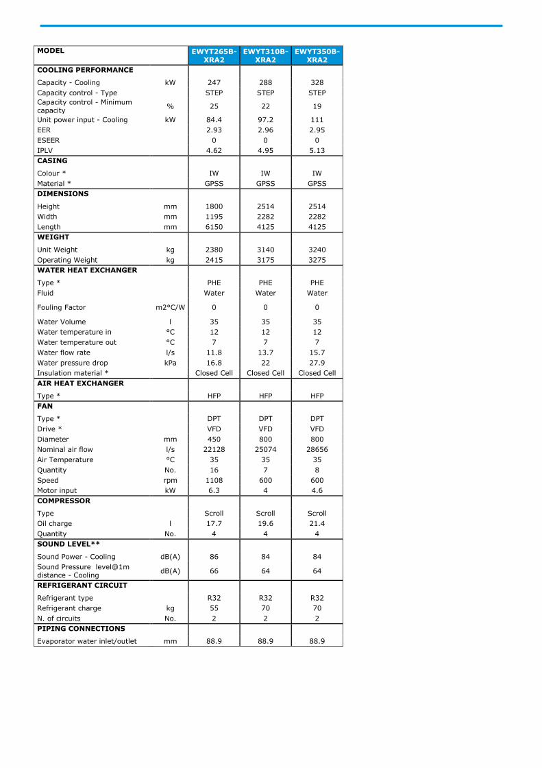
MODEL EWYT265B-XRA2
EWYT310B-XRA2
EWYT350B-XRA2
COOLING PERFORMANCE
Capacity - Cooling kW 247 288 328
Capacity control - Type STEP STEP STEP
Capacity control - Minimum capacity
% 25 22 19
Unit power input - Cooling kW 84.4 97.2 111
EER 2.93 2.96 2.95
ESEER 0 0 0
IPLV 4.62 4.95 5.13
CASING
Colour * IW IW IW
Material * GPSS GPSS GPSS
DIMENSIONS
Height mm 1800 2514 2514
Width mm 1195 2282 2282
Length mm 6150 4125 4125
WEIGHT
Unit Weight kg 2380 3140 3240
Operating Weight kg 2415 3175 3275
WATER HEAT EXCHANGER
Type * PHE PHE PHE
Fluid Water Water Water
Fouling Factor m2°C/W 0 0 0
Water Volume l 35 35 35
Water temperature in °C 12 12 12
Water temperature out °C 7 7 7
Water flow rate l/s 11.8 13.7 15.7
Water pressure drop kPa 16.8 22 27.9
Insulation material * Closed Cell Closed Cell Closed Cell
AIR HEAT EXCHANGER
Type * HFP HFP HFP
FAN
Type * DPT DPT DPT
Drive * VFD VFD VFD
Diameter mm 450 800 800
Nominal air flow l/s 22128 25074 28656
Air Temperature °C 35 35 35
Quantity No. 16 7 8
Speed rpm 1108 600 600
Motor input kW 6.3 4 4.6
COMPRESSOR
Type Scroll Scroll Scroll
Oil charge l 17.7 19.6 21.4
Quantity No. 4 4 4
SOUND LEVEL**
Sound Power - Cooling dB(A) 86 84 84
Sound Pressure level@1m distance - Cooling
dB(A) 66 64 64
REFRIGERANT CIRCUIT
Refrigerant type R32 R32 R32
Refrigerant charge kg 55 70 70
N. of circuits No. 2 2 2
PIPING CONNECTIONS
Evaporator water inlet/outlet mm 88.9 88.9 88.9

TECHNICAL SPECIFICATION
EWYT~B-SS
MODEL EWYT085B-SSA1
EWYT105B-SSA1
EWYT135B-SSA1
EWYT175B-SSA1
EWYT205B-SSA2
EWYT215B-SSA1
HEATING PERFORMANCE
Capacity - Heating kW 82.24 106.24 132.23 169.8 209.28 213.33
Unit power input - Heating kW 28.22 36.59 45.39 59.06 72.51 73.98
COP 2.914 2.903 2.914 2.875 2.886 2.884
SCOP 3.34 3.41 3.36 3.4 3.37 3.4
HEAT EXCHANGER - EVAPORATOR
Water temperature in °C 40 40 40 40 40 40
Water temperature out °C 45 45 45 45 45 45
FAN
Air Temperature 7 7 7 7 7 7
MODEL EWYT235B-SSA2
EWYT255B-SSA2
EWYT300B-SSA2
EWYT340B-SSA2
EWYT390B-SSA2
HEATING PERFORMANCE
Capacity - Heating kW 236.16 256.09 300.01 342.79 389.93
Unit power input - Heating kW 82.26 87.15 104.12 116.23 135.61
COP 2.871 2.938 2.882 2.949 2.875
SCOP 3.34 3.29 3.27 3.28 3.35
HEAT EXCHANGER - EVAPORATOR
Water temperature in °C 40 40 40 40 40
Water temperature out °C 45 45 45 45 45
FAN
Air Temperature 7 7 7 7 7
EWYT~B-SL
MODEL EWYT085B-SLA1
EWYT105B-SLA1
EWYT135B-SLA1
EWYT175B-SLA1
EWYT205B-SLA2
EWYT215B-SLA1
HEATING PERFORMANCE
Capacity - Heating kW 82.24 106.24 132.23 169.8 209.28 213.33
Unit power input - Heating kW 28.22 36.59 45.39 59.06 72.51 73.98
COP 2.914 2.903 2.914 2.875 2.886 2.884
SCOP 3.34 3.41 3.36 3.4 3.37 3.4
HEAT EXCHANGER - EVAPORATOR
Water temperature in °C 40 40 40 40 40 40
Water temperature out °C 45 45 45 45 45 45
FAN
Air Temperature 7 7 7 7 7 7
MODEL EWYT235B-SLA2
EWYT255B-SLA2
EWYT300B-SLA2
EWYT340B-SLA2
EWYT390B-SLA2
HEATING PERFORMANCE
Capacity - Heating kW 236.16 256.09 300.01 342.79 389.93
Unit power input - Heating kW 82.26 87.15 104.12 116.23 135.61
COP 2.871 2.938 2.882 2.949 2.875
SCOP 3.34 3.29 3.27 3.28 3.35
HEAT EXCHANGER - EVAPORATOR
Water temperature in °C 40 40 40 40 40
Water temperature out °C 45 45 45 45 45
FAN
Air Temperature 7 7 7 7 7

ELECTRICAL SPECIFICATIONS
EWYT~B-SR
MODEL EWYT085B-
SRA1 EWYT105B-
SRA1 EWYT135B-
SRA1 EWYT175B-
SRA1 EWYT205B-
SRA2 EWYT215B-
SRA1
HEATING PERFORMANCE
Capacity - Heating kW 74.32 105.24 131.02 152.81 190.75 192.04
Unit power input - Heating kW 26.4 36.24 44.84 54.67 67.74 68.31
COP 2.815 2.904 2.922 2.795 2.816 2.811
SCOP 3.35 3.4 3.37 3.42 3.44 3.43
HEAT EXCHANGER - EVAPORATOR
Water temperature in °C 40 40 40 40 40 40
Water temperature out °C 45 45 45 45 45 45
FAN
Air Temperature 7 7 7 7 7 7
MODEL EWYT235B-
SRA2 EWYT255B-
SRA2 EWYT300B-
SRA2 EWYT340B-
SRA2 EWYT390B-
SRA2
HEATING PERFORMANCE
Capacity - Heating kW 220.83 225.94 295.81 335.24 384.62
Unit power input - Heating kW 77.26 80.08 101.89 113.31 131.71
COP 2.858 2.821 2.903 2.959 2.92
SCOP 3.32 3.33 3.42 3.49 3.49
HEAT EXCHANGER - EVAPORATOR
Water temperature in °C 40 40 40 40 40
Water temperature out °C 45 45 45 45 45
FAN
Air Temperature 7 7 7 7 7
EWYT~B-XS
MODEL EWYT085B-
XSA1 EWYT115B-
XSA1 EWYT135B-
XSA1 EWYT175B-
XSA1 EWYT215B-
XSA1 EWYT215B-
XSA2
HEATING PERFORMANCE
Capacity - Heating kW 85.86 111.02 133.18 176.29 218.29 214.81
Unit power input - Heating kW 26.06 33.19 39.11 51.68 64.91 62.55
COP 3.295 3.345 3.405 3.411 3.363 3.434
SCOP 3.7 3.72 3.7 3.75 3.66 3.7
HEAT EXCHANGER - EVAPORATOR
Water temperature in °C 40 40 40 40 40 40
Water temperature out °C 45 45 45 45 45 45
FAN
Air Temperature 7 7 7 7 7 7
MODEL EWYT235B-
XSA2 EWYT265B-
XSA2 EWYT310B-
XSA2 EWYT350B-
XSA2
HEATING PERFORMANCE
Capacity - Heating kW 239.37 260.83 305.53 349.96
Unit power input - Heating kW 69.49 76.15 88.61 101.7
COP 3.444 3.425 3.448 3.441
SCOP 3.86 3.77 3.9 3.9
HEAT EXCHANGER - EVAPORATOR
Water temperature in °C 40 40 40 40
Water temperature out °C 45 45 45 45
FAN
Air Temperature 7 7 7 7

ELECTRICAL SPECIFICATIONS
EWYT~B-XL MODEL EWYT085B-
XLA1 EWYT085B-
XRA1 EWYT115B-
XLA1 EWYT135B-
XLA1 EWYT175B-
XLA1 EWYT215B-
XLA1
HEATING PERFORMANCE
Capacity - Heating kW 85.86 84.9 111.02 133.18 176.29 218.29
Unit power input - Heating kW 26.06 25.87 33.19 39.11 51.68 64.91
COP 3.295 3.282 3.345 3.405 3.411 3.363
SCOP 3.7 3.66 3.72 3.7 3.75 3.66
HEAT EXCHANGER - EVAPORATOR
Water temperature in °C 40 40 40 40 40 40
Water temperature out °C 45 45 45 45 45 45
FAN
Air Temperature 7 7 7 7 7 7
MODEL EWYT215B-
XLA2 EWYT235B-
XLA2 EWYT265B-
XLA2 EWYT310B-
XLA2 EWYT350B-
XLA2
HEATING PERFORMANCE
Capacity - Heating kW 214.81 239.37 260.83 305.53 349.96
Unit power input - Heating kW 62.55 69.49 76.15 88.61 101.7
COP 3.434 3.444 3.425 3.448 3.441
SCOP 3.7 3.86 3.77 3.9 3.9
HEAT EXCHANGER - EVAPORATOR
Water temperature in °C 40 40 40 40 40
Water temperature out °C 45 45 45 45 45
FAN
Air Temperature 7 7 7 7 7

ELECTRICAL SPECIFICATIONS
EWYT~B-XR
MODEL EWYT115B-
XRA1 EWYT135B-
XRA1 EWYT175B-
XRA1 EWYT215B-
XRA1 EWYT215B-
XRA2 EWYT235B-
XRA2
HEATING PERFORMANCE
Capacity - Heating kW 110.32 132.02 174.14 216.57 213.48 237.57
Unit power input - Heating kW 32.94 38.82 51.3 64.51 62.13 68.99
COP 3.349 3.401 3.394 3.357 3.436 3.443
SCOP 3.71 3.72 3.83 3.74 3.75 3.82
HEAT EXCHANGER - EVAPORATOR
Water temperature in °C 40 40 40 40 40 40
Water temperature out °C 45 45 45 45 45 45
FAN
Air Temperature 7 7 7 7 7 7
MODEL EWYT265B-
XRA2 EWYT310B-
XRA2 EWYT350B-
XRA2
HEATING PERFORMANCE
Capacity - Heating kW 256.58 301.04 344.8
Unit power input - Heating kW 75.49 86.19 98.95
COP 3.399 3.493 3.485
SCOP 3.81 4.06 4.01
HEAT EXCHANGER - EVAPORATOR
Water temperature in °C 40 40 40
Water temperature out °C 45 45 45
FAN
Air Temperature 7 7 7
All the performances (Cooling capacity, unit power input in cooling and EER) are based on the following conditions: 12,0/7,0°C; ambient 35,0°C, unit at full load operation; operating fluid: Water; fouling factor = 0. EN14511:2018
All the performances (Heating capacity, unit power input in heating and COP) are based on the following conditions: 40,0/45,0°C; ambient 7,0°C, unit at full load operation; operating fluid: Water; fouling factor = 0. EN14511:2018
SCOP is based on the following conditions: Tbivalent +2 °C, Tdesign -10 °C, Average ambient conditions, Ref. EN14825. In accordance with standard EN14825, comfort low temperature, average climate, SEER and µs values applicable Ecodesign regulation: (EU) No 2016/2281;
PHE: Plate Heat Exchanger; S&T: Single Pass Shell & Tube; MCH: Microchannel; DPT: Direct Propeller Type; DOL: Direct On Line - VFD: Inverter
Sound power level (referred to 12/7°C, ambient 35°C full load operation) are measured in accordance with ISO 9614 and Eurovent 8/1 for Eurovent certified units. The certification refers only to the overall sound power level, the sound pressure is calculated from the sound power level and are for information only and not considered binding. The minimum capacity indicated is referred to unit operating at standard Eurovent conditions. Dimensions and weights are for indication only and not considered binding. Before designing the installation, consult the official drawings available from the factory at request. All the data are referred to standard unit without options. All data are subject to change without notice
The value refers to the pressure drops in the Water heat exchanger only
ELECTRICAL SPECIFICATIONS
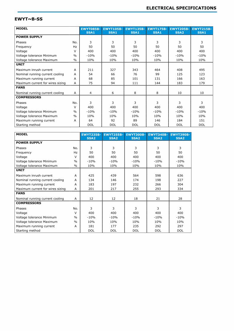
EWYT~B-SS MODEL EWYT085B-
SSA1 EWYT105B-
SSA1 EWYT135B-
SSA1 EWYT175B-
SSA1 EWYT205B-
SSA2 EWYT215B-
SSA1
POWER SUPPLY
Phases No. 3 3 3 3 3 3
Frequency Hz 50 50 50 50 50 50
Voltage V 400 400 400 400 400 400
Voltage tolerance Minimum % -10% -10% -10% -10% -10% -10%
Voltage tolerance Maximum % 10% 10% 10% 10% 10% 10%
UNIT
Maximum inrush current A 211 327 343 464 408 495
Nominal running current cooling A 54 66 76 99 125 123
Maximum running current A 68 85 101 131 166 163
Maximum current for wires sizing A 75 94 111 144 183 179
FANS
Nominal running current cooling A 4 6 8 8 10 10
COMPRESSORS
Phases No. 3 3 3 3 3 3
Voltage V 400 400 400 400 400 400
Voltage tolerance Minimum % -10% -10% -10% -10% -10% -10%
Voltage tolerance Maximum % 10% 10% 10% 10% 10% 10%
Maximum running current A 64 92 89 146 184 151
Starting method DOL DOL DOL DOL DOL DOL
MODEL EWYT235B-
SSA2 EWYT255B-
SSA2 EWYT300B-
SSA2 EWYT340B-
SSA2 EWYT390B-
SSA2
POWER SUPPLY
Phases No. 3 3 3 3 3
Frequency Hz 50 50 50 50 50
Voltage V 400 400 400 400 400
Voltage tolerance Minimum % -10% -10% -10% -10% -10%
Voltage tolerance Maximum % 10% 10% 10% 10% 10%
UNIT
Maximum inrush current A 425 439 564 598 636
Nominal running current cooling A 134 146 174 198 227
Maximum running current A 183 197 232 266 304
Maximum current for wires sizing A 201 217 255 293 334
FANS
Nominal running current cooling A 12 12 18 21 28
COMPRESSORS
Phases No. 3 3 3 3 3
Voltage V 400 400 400 400 400
Voltage tolerance Minimum % -10% -10% -10% -10% -10%
Voltage tolerance Maximum % 10% 10% 10% 10% 10%
Maximum running current A 181 177 235 292 297
Starting method DOL DOL DOL DOL DOL

ELECTRICAL SPECIFICATIONS
EWYT~B-SL
MODEL EWYT085B-
SLA1 EWYT105B-
SLA1 EWYT135B-
SLA1 EWYT175B-
SLA1 EWYT205B-
SLA2 EWYT215B-
SLA1
POWER SUPPLY
Phases No. 3 3 3 3 3 3
Frequency Hz 50 50 50 50 50 50
Voltage V 400 400 400 400 400 400
Voltage tolerance Minimum % -10% -10% -10% -10% -10% -10%
Voltage tolerance Maximum % 10% 10% 10% 10% 10% 10%
UNIT
Maximum inrush current A 211 327 343 464 408 495
Nominal running current cooling A 54 66 76 99 125 123
Maximum running current A 68 85 101 131 166 163
Maximum current for wires sizing A 75 94 111 144 183 179
FANS
Nominal running current cooling A 4 6 8 8 10 10
COMPRESSORS
Phases No. 3 3 3 3 3 3
Voltage V 400 400 400 400 400 400
Voltage tolerance Minimum % -10% -10% -10% -10% -10% -10%
Voltage tolerance Maximum % 10% 10% 10% 10% 10% 10%
Maximum running current A 64 92 89 146 184 151
Starting method DOL DOL DOL DOL DOL DOL
MODEL EWYT235B-
SLA2 EWYT255B-
SLA2 EWYT300B-
SLA2 EWYT340B-
SLA2 EWYT390B-
SLA2
POWER SUPPLY
Phases No. 3 3 3 3 3
Frequency Hz 50 50 50 50 50
Voltage V 400 400 400 400 400
Voltage tolerance Minimum % -10% -10% -10% -10% -10%
Voltage tolerance Maximum % 10% 10% 10% 10% 10%
UNIT
Maximum inrush current A 425 439 564 598 636
Nominal running current cooling A 134 146 174 198 227
Maximum running current A 183 197 232 266 304
Maximum current for wires sizing A 201 217 255 293 334
FANS
Nominal running current cooling A 12 12 18 21 28
COMPRESSORS
Phases No. 3 3 3 3 3
Voltage V 400 400 400 400 400
Voltage tolerance Minimum % -10% -10% -10% -10% -10%
Voltage tolerance Maximum % 10% 10% 10% 10% 10%
Maximum running current A 181 177 235 292 297
Starting method DOL DOL DOL DOL DOL

ELECTRICAL SPECIFICATIONS
EWYT~B-SR MODEL EWYT085B-
SRA1 EWYT105B-
SRA1 EWYT135B-
SRA1 EWYT175B-
SRA1 EWYT205B-
SRA2 EWYT215B-
SRA1
POWER SUPPLY
Phases No. 3 3 3 3 3 3
Frequency Hz 50 50 50 50 50 50
Voltage V 400 400 400 400 400 400
Voltage tolerance Minimum % -10% -10% -10% -10% -10% -10%
Voltage tolerance Maximum % 10% 10% 10% 10% 10% 10%
UNIT
Maximum inrush current A 211 327 343 464 408 495
Nominal running current cooling A 55 67 77 101 128 126
Maximum running current A 68 85 101 131 166 163
Maximum current for wires sizing A 75 94 111 144 183 179
FANS
Nominal running current cooling A 4 6 8 8 9 9
COMPRESSORS
Phases No. 3 3 3 3 3 3
Voltage V 400 400 400 400 400 400
Voltage tolerance Minimum % -10% -10% -10% -10% -10% -10%
Voltage tolerance Maximum % 10% 10% 10% 10% 10% 10%
Maximum running current A 64 92 89 146 184 151
Starting method DOL DOL DOL DOL DOL DOL
MODEL EWYT235B-
SRA2 EWYT255B-
SRA2 EWYT300B-
SRA2 EWYT340B-
SRA2 EWYT390B-
SRA2
POWER SUPPLY
Phases No. 3 3 3 3 3
Frequency Hz 50 50 50 50 50
Voltage V 400 400 400 400 400
Voltage tolerance Minimum % -10% -10% -10% -10% -10%
Voltage tolerance Maximum % 10% 10% 10% 10% 10%
UNIT
Maximum inrush current A 425 439 584 619 658
Nominal running current cooling A 136 149 173 196 223
Maximum running current A 183 197 252 286 325
Maximum current for wires sizing A 201 217 277 315 358
FANS
Nominal running current cooling A 11 11 11 13 18
COMPRESSORS
Phases No. 3 3 3 3 3
Voltage V 400 400 400 400 400
Voltage tolerance Minimum % -10% -10% -10% -10% -10%
Voltage tolerance Maximum % 10% 10% 10% 10% 10%
Maximum running current A 181 177 235 292 297
Starting method DOL DOL DOL DOL DOL

ELECTRICAL SPECIFICATIONS
EWYT~B-XS
MODEL EWYT085B-
XSA1 EWYT115B-
XSA1 EWYT135B-
XSA1 EWYT175B-
XSA1 EWYT215B-
XSA1 EWYT215B-
XSA2
POWER SUPPLY
Phases No. 3 3 3 3 3 3
Frequency Hz 50 50 50 50 50 50
Voltage V 400 400 400 400 400 400
Voltage tolerance Minimum % -10% -10% -10% -10% -10% -10%
Voltage tolerance Maximum % 10% 10% 10% 10% 10% 10%
UNIT
Maximum inrush current A 213 329 343 465 497 412
Nominal running current cooling A 53 65 75 99 123 122
Maximum running current A 70 87 101 133 165 170
Maximum current for wires sizing A 77 96 111 146 182 187
FANS
Nominal running current cooling A 6 8 8 9 11 13
COMPRESSORS
Phases No. 3 3 3 3 3 3
Voltage V 400 400 400 400 400 400
Voltage tolerance Minimum % -10% -10% -10% -10% -10% -10%
Voltage tolerance Maximum % 10% 10% 10% 10% 10% 10%
Maximum running current A 64 92 89 146 151 184
Starting method DOL DOL DOL DOL DOL DOL
MODEL EWYT235B-
XSA2 EWYT265B-
XSA2 EWYT310B-
XSA2 EWYT350B-
XSA2
POWER SUPPLY
Phases No. 3 3 3 3
Frequency Hz 50 50 50 50
Voltage V 400 400 400 400
Voltage tolerance Minimum % -10% -10% -10% -10%
Voltage tolerance Maximum % 10% 10% 10% 10%
UNIT
Maximum inrush current A 429 443 572 606
Nominal running current cooling A 132 143 170 192
Maximum running current A 186 201 240 274
Maximum current for wires sizing A 205 221 264 301
FANS
Nominal running current cooling A 15 15 15 17
COMPRESSORS
Phases No. 3 3 3 3
Voltage V 400 400 400 400
Voltage tolerance Minimum % -10% -10% -10% -10%
Voltage tolerance Maximum % 10% 10% 10% 10%
Maximum running current A 181 177 235 292
Starting method DOL DOL DOL DOL

ELECTRICAL SPECIFICATIONS
EWYT~B-XL
MODEL EWYT085B-
XLA1 EWYT085B-
XRA1 EWYT115B-
XLA1 EWYT135B-
XLA1 EWYT175B-
XLA1 EWYT215B-
XLA1
POWER SUPPLY
Phases No. 3 3 3 3 3 3
Frequency Hz 50 50 50 50 50 50
Voltage V 400 400 400 400 400 400
Voltage tolerance Minimum % -10% -10% -10% -10% -10% -10%
Voltage tolerance Maximum % 10% 10% 10% 10% 10% 10%
UNIT
Maximum inrush current A 213 213 329 343 465 497
Nominal running current cooling A 53 53 65 75 99 123
Maximum running current A 70 70 87 101 133 165
Maximum current for wires sizing A 77 77 96 111 146 182
FANS
Nominal running current cooling A 6 5 8 8 9 11
COMPRESSORS
Phases No. 3 3 3 3 3 3
Voltage V 400 400 400 400 400 400
Voltage tolerance Minimum % -10% -10% -10% -10% -10% -10%
Voltage tolerance Maximum % 10% 10% 10% 10% 10% 10%
Maximum running current A 64 64 92 89 146 151
Starting method DOL DOL DOL DOL DOL DOL
MODEL EWYT215B-
XLA2 EWYT235B-
XLA2 EWYT265B-
XLA2 EWYT310B-
XLA2 EWYT350B-
XLA2
POWER SUPPLY
Phases No. 3 3 3 3 3
Frequency Hz 50 50 50 50 50
Voltage V 400 400 400 400 400
Voltage tolerance Minimum % -10% -10% -10% -10% -10%
Voltage tolerance Maximum % 10% 10% 10% 10% 10%
UNIT
Maximum inrush current A 412 429 443 572 606
Nominal running current cooling A 122 132 143 170 192
Maximum running current A 170 186 201 240 274
Maximum current for wires sizing A 187 205 221 264 301
FANS
Nominal running current cooling A 13 15 15 15 17
COMPRESSORS
Phases No. 3 3 3 3 3
Voltage V 400 400 400 400 400
Voltage tolerance Minimum % -10% -10% -10% -10% -10%
Voltage tolerance Maximum % 10% 10% 10% 10% 10%
Maximum running current A 184 181 177 235 292
Starting method DOL DOL DOL DOL DOL

ELECTRICAL SPECIFICATIONS
EWYT~B-XR MODEL EWYT115B-
XRA1 EWYT135B-
XRA1 EWYT175B-
XRA1 EWYT215B-
XRA1 EWYT215B-
XRA2 EWYT235B-
XRA2
POWER SUPPLY
Phases No. 3 3 3 3 3 3
Frequency Hz 50 50 50 50 50 50
Voltage V 400 400 400 400 400 400
Voltage tolerance Minimum % -10% -10% -10% -10% -10% -10%
Voltage tolerance Maximum % 10% 10% 10% 10% 10% 10%
UNIT
Maximum inrush current A 329 343 465 497 412 429
Nominal running current cooling A 65 75 100 124 123 133
Maximum running current A 87 101 133 165 170 186
Maximum current for wires sizing A 96 111 146 182 187 205
FANS
Nominal running current cooling A 7 7 9 11 13 14
COMPRESSORS
Phases No. 3 3 3 3 3 3
Voltage V 400 400 400 400 400 400
Voltage tolerance Minimum % -10% -10% -10% -10% -10% -10%
Voltage tolerance Maximum % 10% 10% 10% 10% 10% 10%
Maximum running current A 92 89 146 151 184 181
Starting method DOL DOL DOL DOL DOL DOL
MODEL EWYT265B-
XRA2 EWYT310B-
XRA2 EWYT350B-
XRA2
POWER SUPPLY
Phases No. 3 3 3
Frequency Hz 50 50 50
Voltage V 400 400 400
Voltage tolerance Minimum % -10% -10% -10%
Voltage tolerance Maximum % 10% 10% 10%
UNIT
Maximum inrush current A 443 572 606
Nominal running current cooling A 145 169 192
Maximum running current A 201 240 274
Maximum current for wires sizing A 221 264 301
FANS
Nominal running current cooling A 14 10 11
COMPRESSORS
Phases No. 3 3 3
Voltage V 400 400 400
Voltage tolerance Minimum % -10% -10% -10%
Voltage tolerance Maximum % 10% 10% 10%
Maximum running current A 177 235 292
Starting method DOL DOL DOL
Fluid: Water Allowed voltage tolerance ± 10%, Voltage unbalance between phases must be within ± 3%.
Maximum starting current: In case of inverter driven units, no inrush current at start up is experienced.
Nominal current in cooling mode is referred to the following conditions: Water Side Heat Exchanger 12/7°C; ambient 35°C;
compressors + fans current
Maximum running current is based on max compressor absorbed current in its envelope and max fans absorbed current Maximum unit current for wires sizing is based on minimum allowed voltage
Maximum current for wires sizing: (compressors full load ampere + fans current) x 1,1
The data are referred to the standard unit without options
For the electrical data of the hydronic kit refer to "Options technical data"
All data are subject to change without notice, Please refer to unit nameplate data

SOUND LEVELS
EWYT~B-SS
Sound pressure level at 1 m from the unit Sound
Power
MODEL 63 Hz 125 Hz 250 Hz 500 Hz 1000 Hz 2000 Hz 4000 Hz 8000 Hz db(A) db (A)
EWYT085B-SSA1
69.2 68.3 64.1 63.3 61.7 59.2 54.8 49.0 83.8 66.4
EWYT105B-SSA1
70.6 69.7 65.7 64.6 63.0 63.2 56.7 49.6 87.2 69.4
EWYT135B-SSA1
71.5 70.6 66.7 65.5 63.9 65.0 57.9 50.0 89.1 70.9
EWYT175B-SSA1
71.5 70.6 66.8 65.9 67.9 67.1 60.0 51.4 90.8 72.6
EWYT215B-SSA1
72.1 71.2 67.4 66.7 69.8 68.3 61.2 52.5 92.2 73.7
EWYT205B-SSA2
72.0 71.0 67.1 66.0 64.6 65.2 58.6 51.4 89.9 71.2
EWYT235B-SSA2
72.4 71.5 67.6 66.5 65.0 66.1 59.2 51.5 91.0 72.0
EWYT255B-SSA2
72.4 71.5 67.7 66.5 65.2 67.0 59.7 51.6 91.7 72.7
EWYT300B-SSA2
81.1 75.5 74.6 72.7 69.8 68.5 61.4 57.3 94.0 74.5
EWYT340B-SSA2
81.9 76.2 75.3 73.6 71.3 69.5 62.5 58.2 94.9 75.4
EWYT390B-SSA2
82.7 77.0 76.1 74.3 72.2 69.9 63.0 58.9 95.9 75.9
EWYT~B-SL
Sound pressure level at 1 m from the unit Sound
Power
MODEL 63 Hz 125 Hz 250 Hz 500 Hz 1000 Hz 2000 Hz 4000 Hz 8000 Hz db(A) db (A)
EWYT085B-SLA1
69.2 68.3 64.0 63.0 60.9 57.0 52.4 46.6 82.7 65.3
EWYT105B-SLA1
70.6 69.7 65.5 64.3 62.2 59.9 54.1 47.5 85.2 67.4
EWYT135B-SLA1
71.5 70.6 66.4 65.2 63.1 61.4 55.1 48.2 86.8 68.6
EWYT175B-SLA1
71.5 70.6 66.4 65.4 65.1 63.1 56.5 48.9 87.8 69.6
EWYT215B-SLA1
72.1 71.2 67.1 66.1 66.5 64.2 57.6 49.8 89.0 70.5
EWYT205B-SLA2
72.0 71.0 66.8 65.7 63.7 61.7 55.8 49.1 87.7 69.0
EWYT235B-SLA2
72.4 71.5 67.4 66.2 64.1 62.5 56.3 49.4 88.6 69.6
EWYT255B-SLA2
72.4 71.5 67.4 66.2 64.2 63.1 56.6 49.5 89.0 70.0
EWYT300B-SLA2
81.1 75.4 74.5 72.6 67.7 62.4 56.9 56.4 90.8 71.3
EWYT340B-SLA2
81.9 76.2 75.2 73.4 68.6 63.2 57.8 57.2 91.6 72.1
EWYT390B-SLA2 82.7 77.0 76.0 74.1 69.4 63.9 58.5 58.0 92.8 72.8
Sound power level (referred to Water Side Heat Exchanger 12/7°C, ambient 35°C full load operation) are measured in accordance with ISO 9614 and Eurovent 8/1 for Eurovent certified units, The certification refers only to the overall sound power level. The sound data in the Octave band spectrum is for intended for reference only and not considering binding. The sound pressure is calculated from the sound power level and are for information only and not considered
binding.

SOUND LEVELS
EWYT~B-SR
Sound pressure level at 1 m from the unit Sound
Power
MODEL 63 Hz 125 Hz 250 Hz 500 Hz 1000 Hz 2000 Hz 4000 Hz 8000 Hz db(A) db (A)
EWYT085B-SRA1 63.2 64.6 59.3 59.3 57.1 53.4 48.9 43.0 77.8 60.4
EWYT105B-SRA1 65.6 67.0 61.8 61.7 59.4 58.3 51.8 44.6 81.6 63.8
EWYT135B-SRA1 66.4 67.9 62.8 62.5 60.3 60.0 53.0 45.0 83.6 65.4
EWYT175B-SRA1 66.4 67.9 62.9 62.8 63.5 62.2 55.0 46.5 85.4 67.2
EWYT215B-SRA1 67.1 68.5 63.5 63.6 65.2 63.4 56.3 47.5 86.9 68.4
EWYT205B-SRA2 66.9 68.3 63.2 63.1 60.9 60.2 53.7 46.4 84.4 65.7
EWYT235B-SRA2 67.4 68.8 63.7 63.5 61.4 61.2 54.3 46.5 85.5 66.5
EWYT255B-SRA2 67.4 68.8 63.8 63.6 61.5 62.0 54.8 46.6 86.3 67.3
EWYT300B-SRA2 74.6 68.8 67.6 64.5 62.1 58.9 55.1 55.3 87.2 67.7
EWYT340B-SRA2 75.4 69.6 68.4 65.3 63.2 59.8 55.9 56.1 88.0 68.5
EWYT390B-SRA2 76.2 70.4 69.1 66.1 64.1 60.4 56.6 56.9 89.2 69.2
EWYT~B-XS
Sound pressure level at 1 m from the unit Sound
Power
MODEL 63 Hz 125 Hz 250 Hz 500 Hz 1000 Hz 2000 Hz 4000 Hz 8000 Hz db(A) db (A)
EWYT085B-XSA1 65.6 67.0 61.7 62.0 60.3 57.9 53.5 47.7 81.2 63.4
EWYT115B-XSA1 66.4 67.9 63.0 62.9 61.3 62.3 55.5 47.9 85.6 67.4
EWYT135B-XSA1 66.4 67.9 63.4 63.0 61.7 64.4 56.8 48.1 87.6 69.4
EWYT175B-XSA1 67.1 68.5 64.0 64.2 66.9 66.5 59.1 50.0 89.9 71.4
EWYT215B-XSA1 67.6 69.0 64.5 65.0 69.0 67.8 60.4 51.2 91.4 72.6
EWYT215B-XSA2 67.8 69.2 64.4 64.3 62.8 64.1 57.3 49.7 88.5 69.2
EWYT235B-XSA2 68.1 69.5 64.8 64.6 63.1 65.1 57.9 49.7 89.7 70.2
EWYT265B-XSA2 68.1 69.5 65.0 64.7 63.4 66.1 58.5 49.8 90.6 71.1
EWYT310B-XSA2 75.6 69.8 68.9 66.2 67.1 67.5 60.7 57.1 92.4 72.4
EWYT350B-XSA2 76.2 70.4 69.5 67.0 69.0 68.5 61.7 57.8 93.4 73.4
Sound power level (referred to Water Side Heat Exchanger 12/7°C, ambient 35°C full load operation) are measured in accordance with ISO 9614 and Eurovent 8/1 for Eurovent certified units, The certification refers only to the overall sound power level. The sound data in the Octave band spectrum is for intended for reference only and not considering binding. The sound pressure is calculated from the sound power level and are for information only and not considered binding.

SOUND LEVELS
EWYT~B-XL
Sound pressure level at 1 m from the unit Sound
Power
MODEL 63 Hz 125 Hz 250 Hz 500 Hz 1000 Hz 2000 Hz 4000 Hz 8000 Hz db(A) db (A)
EWYT085B-XLA1 65.6 67.0 61.6 61.6 59.2 54.8 50.3 44.4 79.0 61.2
EWYT115B-XLA1 66.4 67.9 62.6 62.5 60.1 58.3 52.0 44.9 82.1 63.9
EWYT135B-XLA1 66.4 67.9 62.8 62.5 60.3 60.0 53.0 45.0 83.6 65.4
EWYT175B-XLA1 67.1 68.5 63.4 63.4 63.5 62.0 54.9 46.5 85.7 67.2
EWYT215B-XLA1 67.6 69.0 63.9 64.0 65.2 63.1 56.1 47.5 87.0 68.2
EWYT215B-XLA2 67.8 69.2 64.0 63.9 61.5 60.0 53.7 46.5 84.9 65.6
EWYT235B-XLA2 68.1 69.5 64.4 64.2 61.8 60.9 54.2 46.6 85.9 66.4
EWYT265B-XLA2 68.1 69.5 64.4 64.2 61.9 61.7 54.6 46.7 86.6 67.1
EWYT310B-XLA2 75.6 69.8 68.6 65.5 62.9 59.3 55.8 56.3 86.4 66.4
EWYT350B-XLA2 76.2 70.4 69.1 66.1 63.8 60.1 56.5 56.9 87.1 67.1
EWYT~B-XR
Sound pressure level at 1 m from the unit Sound
Power
MODEL 63 Hz 125 Hz 250 Hz 500 Hz 1000 Hz 2000 Hz 4000 Hz 8000 Hz db(A) db (A)
EWYT085B-XRA1 61.7 64.6 58.6 59.3 56.7 52.7 48.2 42.3 77.1 59.3
EWYT115B-XRA1 63.6 66.5 60.7 61.2 58.7 57.6 51.0 43.6 81.0 62.8
EWYT135B-XRA1 63.6 66.5 60.9 61.2 58.9 59.6 52.3 43.8 82.9 64.7
EWYT175B-XRA1 64.2 67.1 61.5 62.1 62.8 61.7 54.4 45.6 85.1 66.6
EWYT215B-XRA1 64.7 67.6 62.0 62.8 64.6 62.9 55.7 46.6 86.5 67.7
EWYT215B-XRA2 64.9 67.8 62.1 62.5 60.1 59.5 52.8 45.3 83.9 64.6
EWYT235B-XRA2 65.3 68.2 62.5 62.9 60.4 60.4 53.4 45.4 85.0 65.5
EWYT265B-XRA2 65.3 68.2 62.6 62.9 60.6 61.3 53.9 45.5 85.9 66.4
EWYT310B-XRA2 72.4 66.5 65.1 61.5 60.3 57.9 54.9 55.8 83.6 63.6
EWYT350B-XRA2 73.0 67.1 65.7 62.1 61.4 58.7 55.6 56.3 84.3 64.3
Sound power level (referred to Water Side Heat Exchanger 12/7°C, ambient 35°C full load operation) are measured in accordance with ISO 9614 and Eurovent 8/1 for Eurovent certified units, The certification refers only to the overall sound power level. The sound data in the Octave band spectrum is for intended for reference only and not considering binding. The sound pressure is calculated from the sound power level and are for information only and not considered
binding.

ENVELOPE
EWYT~B-S (SILVER SERIES) - Parallel and Double V Coil
EWYT~B-X (GOLD SERIES) - Parallel and Double V Coil
The above graph refers to the unit operating at full load. Unit may be able to operate outside the above envelope with compressors
unloading. Please contact factory for further details.
The above graphic represents a guideline about the operating limits of the range. Please refer to the latest Unit Selection Software
(CSS) for real operating limits working conditions for each size.
15
20
25
30
35
40
45
50
55
60
65
-20 -15 -10 -5 0 5 10 15 20 25 30 35 40BPH
E C
ondenser
Leavin
g W
ate
r Tem
pera
ture
[°C]
Outside Ambient Temperature [°C]
Heating
SS-SL FULL LOAD SR FULL LOAD SS-SL PARTIAL LOAD SR PARTIAL LOAD
15
20
25
30
35
40
45
50
55
60
65
-20 -15 -10 -5 0 5 10 15 20 25 30 35 40
BPH
E C
ondenser
Leavin
g W
ate
r Tem
pera
ture
[°C]
Outside Ambient Temperature [°C]
Heating
XS-XL FULL LOAD XR FULL LOAD XS-XL PARTIAL LOAD XR PARTIAL LOAD

ENVELOPE
EWYT~B-S (SILVER SERIES) – Parallel Coil
EWYT~B-X (GOLD SERIES) - Parallel Coil
-15
-10
-5
0
5
10
15
20
25
30
35
40
45
50
-15 -10 -5 0 5 10 15 20 25
Outs
ide A
mbie
nt
Tem
pera
ture
[°C]
Evaporator Leaving Water Temperature [°C]
Cooling
-15
-10
-5
0
5
10
15
20
25
30
35
40
45
50
-15 -10 -5 0 5 10 15 20 25
Outs
ide A
mbie
nt
Tem
pera
ture
[°C]
Evaporator Leaving Water Temperature [°C]
Cooling

ENVELOPE
EWYT~B-S (SILVER SERIES) – Double V Coil
EWYT~B-X (GOLD SERIES) – Double V Coil
For operations below 4°C Water Side Heat Exchanger Leaving Temperature please contact
factory.
The above graphic represents a guideline about the operating limits of the range. Please refer
to the latest Unit Selection Software (CSS) for real operating limits working conditions for
each size.
-20-15-10-505
10152025303540455055
-15 -10 -5 0 5 10 15 20 25Outs
ide A
mbie
nt
Tem
pera
ture
[°C]
Evaporator Leaving Water Temperature [°C]
Cooling
VFD or Speedtroll
-20
-15
-10
-5
0
5
10
15
20
25
30
35
40
45
50
55
-15 -10 -5 0 5 10 15 20 25
Outs
ide A
mbie
nt
Tem
pera
ture
[°C]
Evaporator Leaving Water Temperature [°C]
Cooling
Contact Factory
VFD or Speedtroll
Contact Factory

ENVELOPE
Water heat exchanger - maximum/maximum water Δt The minimum and maximum allowed Δt at full load conditioins are respectively 2,5 °C and 10°C. Contact factory in case lower or higher Δt are required. Minimum and maximum Water Side Heat Exchanger flows are to be respected withing the Δt range above.
Water flow The following tables indicate the minimum and maximum water flow allowed for each model.
The minimum flow indicated correspond to the minimum flow allowed at minimum load for the unit. It is not
intended as minimum flow allowed for unit full load operation.
For minimum flow allowed (maximum deltaT) in full load operation refer to Selection Software.
The below values are referred to pure water (in case of glycol mixture contact factory).
Note: the performances are certified at standard conditions and with the unit operating with the nominal water
flow.
Model Min Flow [l/s]
Max Flow [l/s]
Model Min Flow [l/s]
Max Flow [l/s]
EWYT085B-SS(L)(R)A1 2.5 12.5 EWYT085B-XS(L)(R)A1 3.6 17.0
EWYT105B-SS(L)(R)A1 2.5 12.5 EWYT115B-XS(L)(R)A1 3.6 17.0
EWYT135B-SS(L)(R)A1 2.5 12.5 EWYT135B-XS(L)(R)A1 3.6 17.0
EWYT175B-SS(L)(R)A1 2.5 12.5 EWYT175B-XS(L)(R)A1 5.0 22.9
EWYT215B-SS(L)(R)A1 3.6 17.0 EWYT215B-XS(L)(R)A1 5.0 22.9
EWYT205B-SS(L)(R)A2 3.6 17.0 EWYT215B-XS(L)(R)A2 8.9 31.2
EWYT235B-SS(L)(R)A2 3.6 17.0 EWYT235B-XS(L)(R)A2 8.9 31.2
EWYT255B-SS(L)(R)A2 4.4 19.9 EWYT265B-XS(L)(R)A2 8.9 31.2
EWYT300B-SS(L)(R)A2 4.4 19.9 EWYT310B-XS(L)(R)A2 8.9 31.2
EWYT340B-SS(L)(R)A2 5.6 26.4 EWYT350B-XS(L)(R)A2 8.9 31.2
EWYT390B-SS(L)(R)A2 5.6 26.4
Minimum glycol percentage for low air ambient temperature to prevent freezing of the hydraulic circuit
AMBIENT T [°C] -3 -8 -15 -20 AMBIENT T [°C] -3 -8 -15 -20
ETHYLENE GLYCOL 10% 20% 30% 40% PROPYLENE GLYCOL 10% 20% 30% 40%
The presence of glycol in the water system will affect unit performances. Refer to the selection software for
details. All machine protection systems, such as antifreeze and low-pressure protection will need to be set in accordance to the type and percentage of the glycol and plant requirements.
Air heat exchanger - Altitude correction factors
ELEVATION ABOVE SEA LEVEL [m] 0 300 600 900 1200 1500 1800
BAROMETRIC PRESSURE [mbar] 1013 997 942 908 875 843 812
COOLING CAPACITY CORRECTION FACTOR 1 0,993 0,986 0,979 0,973 0,967 0,96
POWER INPUT CORRECTION FACTOR 1 1,005 1,009 1,015 1,021 1,026 1,031
Maximum operating altitude is 1800 m above sea level.
Contact factory if the unit has to be installed 1000 m above the sea level.

ENVELOPE
Available fan static pressure correction factors
EXTERNAL STATIC PRESSURE [Pa] 0 10 20 30
COOLING CAPACITY CORRECTION FACTOR 1 0,998 0,995 0,990
COMPRESSOR POWER INPUTCORRECTION FACTOR 1 1,006 1,010 1,020
REDUCTION OF MAX OPERATING AMBIENT TEMPERATURE [°C] 1 -0,3 -0,5 -1
The above table is valid for SILVER and GOLD series with standard and VFD driven fans. Application with more than 30 Pa of external static pressure are not recommended. In case where external static pressure over 30
Pa is required special high ESP fans are required.
Partial Heat recovery Units may be optionally equipped with heat recovery system. This system is made
by a water -cooled heat exchanger located on the compressors discharge pipe and a dedicated management of
condensing pressure.
To guarantee compressor operation within its envelope, units with heat recovery cannot operate with water
temperature of the heat recovery water lower than 25°C.
It is a responsibility of plant designer and unit installer to guarantee the respect of this value (e.g. using
recirculating bypass valve).
Plant water content The cooled water distribution circuits should have minimum water content to avoid
excessive compressors start and stop. In fact, each time the compressor starts up, an excessive quantity of oil
goes from the compressor sump and simultaneously there is a rise in the temperature of the compressor motor’s
stator due to the inrush current during the start – up. To prevent damage to the compressors, have been
envisaged the application of a device to limit frequent stops and restarts. During the span of one hour there will be no more than 10 starts of the compressor. The plant side should
therefore ensure that the overall water content allows a more constant functioning of the unit and consequently
greater environmental comfort.
The calculation of the water content should also consider the plant’s design parameters.
As a general indication the water content should not be less than 5 lt/kW on single circuit units and 2,5l/kW on
the twin circuit units.
Note: The indication is intended as a general guideline and not intended to substitute the evaluation made by
qualified technical personnel or by HVAC engineers, For more detailed analysis is better to consider the use of
other more detailed approach.
Water quality Before putting the unit into operation, clean the water circuit, Dirt, scales, corrosion debrits
and other material can accumulate inside the heat exchanger and reduce its heat exchanging capacity. Pressure
drop can increase as well, thus reducing water flow. Proper water treatment therefore reduces the risk of
corrosion, erosion, scaling, etc. The most appropriate water treatment must be determined locally, according to
the type of system and water characteristics. The manufacturer is not responsible for damage to or malfunctioning of equipment caused by failure to treat water or by improperly treated water.

INSTALLATIONS NOTES
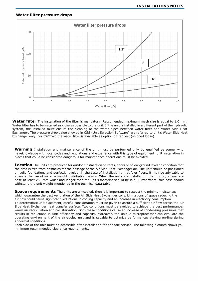
INSTALLATIONS NOTES
Water filter pressure drops
Water filter The installation of the filter is mandatory. Reccomended maximum mesh size is equal to 1,0 mm.
Water filter has to be installed as close as possible to the unit. If the unit is installed in a different part of the hydraulic system, the installed must ensure the cleaning of the water pipes between water filter and Water Side Heat Exchanger. The pressure drop value showed in CSS (Unit Selection Software) are referred to unit’s Water Side Heat Exchanger only. For EWYT~B the water filter is available as option on request (shipped loose).
Warning Installation and maintenance of the unit must be performed only by qualified personnel who
haveknowledge with local codes and regulations and experience with this type of equipment, unit installation in
places that could be considered dangerous for maintenance operations must be avoided.
Location The units are produced for outdoor installation on roofs, floors or below ground level on condition that
the area is free from obstacles for the passage of the Air Side Heat Exchanger air. The unit should be positioned
on solid foundations and perfectly leveled; in the case of installation on roofs or floors, it may be advisable to
arrange the use of suitable weight distribution beams. When the units are installed on the ground, a concrete
base at least 250 mm wider and longer than the unit’s footprint should be laid. Furthermore, this base should
withstand the unit weight mentioned in the technical data table.
Space requirements The units are air-cooled, then it is important to respect the minimum distances
which guarantee the best ventilation of the Air Side Heat Exchanger coils. Limitations of space reducing the
air flow could cause significant reductions in cooling capacity and an increase in electricity consumption.
To determinate unit placement, careful consideration must be given to assure a sufficient air flow across the Air
Side Heat Exchanger heat transfer surface. Two conditions must be avoided to achieve the best performance:
warm air recirculation and coil starvation. Both these conditions cause an increase of condensing pressures that
results in reductions in unit efficiency and capacity. Moreover, the unique microprocessor can evaluate the operating environment of the air-cooled unit and is capable to optimize performances staying on-line during
abnormal conditions.
Each side of the unit must be accessible after installation for periodic service. The following pictures shows you
minimum recommended clearance requirements.
0
50
100
150
0 5 10 15 20 25 30 35 40
Exte
rnal
pre
ssu
re h
ead
[kP
a]
Water flow [l/s]
Water filter pressure drops
2.5"
3"
4"

INSTALLATIONS NOTES
Parallel Coil Double V Coil
A 1100 mm 2200 mm
B 1100 mm 1500 mm
For single unit installation in proximity of a wall the following indications are recommended:
- if h < Hc → L must at least 3 m for Double V Coil layout units or 1,8m for Parallel Coil layout units
- if h ≥ Hc or L lower than recommended contact Daikin representative to evaluate possible arrangements
In case two units installed side by side in free filed, the minimum distance recommended between the units is
indicated in the below picture
For mutliple unit installation it is recommended to install the units is a single row as hown in the picture below
For additional information refer to the Installation Manual. If the site does not allow this kind of installation contact Daikin representative to evaluate possible arrangements.

INSTALLATIONS NOTES
Multiple units installation – free field with wind prevalent direction Considering an installation in areas with prevailing wind direction (as represented in the first image below): - Unit n,1: operates with no air overtemperature - Unit n,2: operates in heated environment caused by Unit n,1 and by itself
- Unit n,3: operates in partially heated environment caused by Unit n,2 To reduce the effect of prevailing wind, it is opportune to set the units main dimension parallel to the wind prevailing
wind (as represented in the second image below).
Multiple units installation – closed area with wind prevalent direction In case of closed area with height equal or higher than the units, installation is the installation is not recommended. Units 2 and 3 operate at significantly higher temperatures due to the higher recirculation. In this case it is necessary to adopt special precautions based on the specific installation (for example: walls with grids, installation of the unit
on base to increase its height, duct on fans, high head fans, etc,)
Water filter The installation of the filter is mandatory. Reccomended maximum mesh size is equal to 1,0 mm.
Water filter has to be installed as close as possible to the unit. If the unit is installed in a different part of the hydraulic system, the installed must ensure the cleaning of the water pipes between water filter and Water Side Heat Exchanger. The pressure drop value showed in CSS (Unit Selection Software) are referred to unit’s Water Side Heat Exchanger only. For EWYT~B the water filter is available as option on request (shipped loose).
Unit n.1 Unit n.2 Unit n.3
Unit n.1 Unit n.2 Unit n.3
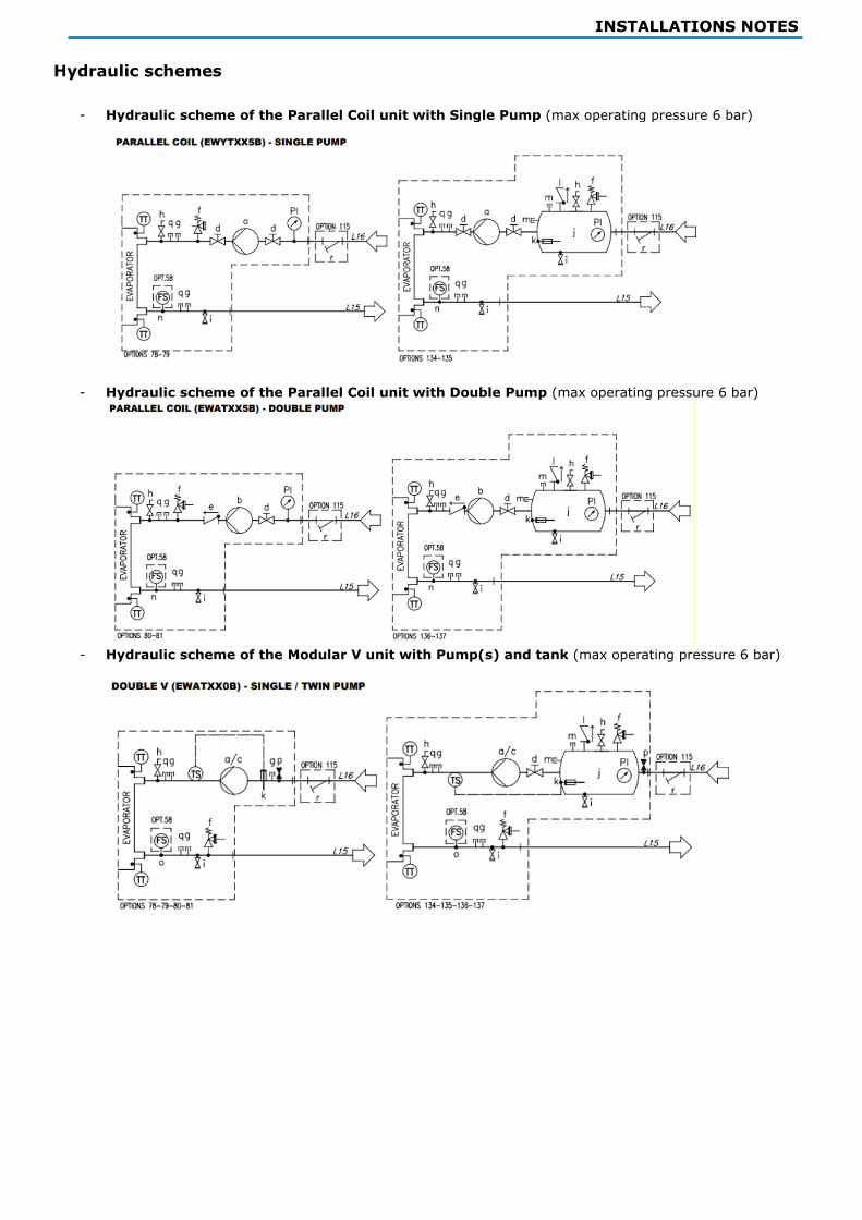
INSTALLATIONS NOTES
Hydraulic schemes
- Hydraulic scheme of the Parallel Coil unit with Single Pump (max operating pressure 6 bar)
- Hydraulic scheme of the Parallel Coil unit with Double Pump (max operating pressure 6 bar)
- Hydraulic scheme of the Modular V unit with Pump(s) and tank (max operating pressure 6 bar)

INSTALLATIONS NOTES
General The unit will be designed and manufactured in accordance with the following European directives: • Construction of pressure vessel 2014/68/EU
• Machinery Directive 2006/42/EC • Low Voltage 2014/35/EU
• Electromagnetic Compatibility 2014/30/EU • Electrical & Safety codes EN 60204–1 / EN 60335-2-40
• Manufacturing Quality Standards UNI – UNI EN ISO 1400
The unit will be tested at full load in the factory (at the nominal working conditions and water temperatures). The unit will be delivered to the job site completely assembled and charged with refrigerant and oil.
The installation of the unit must comply with the manufacturer’s instructions for rigging and handling equipment.
The unit will be able to start up and operate (as standard) at full load with:
- Outside air temperature from............... °C to............... °C
- Water Side Heat Exchanger leaving fluid temperature between............... °C and............... °C
Refrigerant HFC R-32
Performance Unit shall supply the following performances:
• Number of unit(s):............... unit(s) • Cooling capacity for single unit:............... kW
• Power input for single unit in cooling mode:............... kW • Heat exchanger entering water temperature in cooling mode:............... °C
• Heat exchanger leaving water temperature in cooling mode:............... °C • Heat exchanger water flow in cooling:............... l/s
• Nominal outside working ambient temperature in cooling mode:............... °C • Minimum full load efficiency (EER): …………….. (kW/kW)
• Minimum part load efficiency (SEER): …………….. (kW/kW) • Heating capacity for single unit:............... kW
• Power input for single unit in heating mode:............... kW
INSTALLATIONS NOTES
• Heat exchanger entering water temperature in heating mode:............... °C
• Heat exchanger leaving water temperature in heating mode:............... °C
• Heat exchanger water flow in heating:............... l/s
• Nominal outside working ambient temperature in heating mode:............... °C • Minimum full load efficiency (COP): …………….. (kW/kW)
• Minimum part load efficiency (SCOP): …………….. (kW/kW)
Operating voltage range should be 400V ±10%, 3ph, 50Hz (or 380V ±10%, 3ph, 60Hz), voltage unbalance
maximum 3%, without neutral conductor and shall only have one power connection point.
Unit description Unit shall include one or two independent refrigerant circuits, hermetic orbiting scroll type
optimized for R-32 operation, electronic expansion device (EEXV), direct expansion, PHE Water Side Heat Exchanger, air-cooled Air Side Heat Exchanger section made with aluminum Microchannel technology, R-32
refrigerant, lubrication system, motor starting components, control system and all components necessary
for a safe and stable unit operation.
The unit will be factory assembled on a robust base frame made of galvanized steel, protected by an epoxy
paint.
Sound level and vibrations Sound power level shall not exceed ………dB(A). The sound power levels must be
rated in accordance to ISO 9614 (other types of rating cannot be used). Vibration on the base frame should not exceed 2 mm/s.
Dimensions Unit dimensions shall not exceed following indications:
- Unit length............... mm - Unit width............... mm
- Unit height............... mm
Compressors
Hermetic orbiting scroll type optimized for R-32 operation and complete with motor over-temperature and
over-current protection devices. Each compressor equipped with oil heater that keeps the oil from being
diluted by the refrigerant when the unit is not running. Each compressor is mounted on rubber antivibration
mounts for a quite operation. Unit is delivered with complete oil charge.
Water Side Heat Exchanger
The units shall be equipped with a direct expansion plate to plate type Water Side Heat Exchanger
• The Water Side Heat Exchanger will be made of stainless steel brazed plates and shall be linked with an
electrical heater controlled by a thermostat and shall be insulated with flexible, closed cell polyurethane
insulation material
• The water connections shall be VICTAULIC type connections as standard to ensure quick mechanical disconnection between the unit and the hydronic network • The Water Side Heat Exchanger will be manufactured in accordance to PED approval
• Flow switch on Water Side Heat Exchanger available as option (shipped loose)
• Water folter on Water Side Heat Exchangeravailable as option (shipped loose)
Air Side Heat Exchanger coil The Air Side Heat Exchanger is made entirely of aluminum with flat tubes
containing small channels.
Full - depth louvered aluminum fins are inserted between the tubes maximizing the heat exchange.
The Microchannel technology ensures the highest performance with the minimum surface for the exchanger. The
quantity of refrigerant is also reduced compared to Cu/Al Air Side Heat Exchanger, Special treatments ensure
resistance to thecorrosion by atmospheric agents extending the life time (available on request).
Air Side Heat Exchanger fans The Air Side Heat Exchanger fans used in conjunction with the Air Side Heat
Exchanger coils, shall be propeller with glass reinforced resin blades for higher efficiencies and lower sound.
Each fan shall be protected by a fan guard. • The air discharge shall be vertical and each fan must be coupled to the electrical motor, supplied as standard
to IP54 and capable to work to ambient temperatures of - 20°C to + 65°C.
• The Air Side Heat Exchanger fans shall have as a standard a thermally protection by internal thermal motor.
Refrigerant circuit The unit shall have one or two independent refrigerant.
• The circuit shall include as standard: electronic expansion device dived by unit’s microprocessor control,
liquid line shut-off valve, sight glass with moisture indicator, filter drier, charging valves, high pressure
switch, high and low pressure transducers, oil pressure transducer and insulated suction line, Condensation control. The units will be provided with an automatic control for condensing pressure which ensures the
working at low external temperatures down to - …………… °C, to maintain condensing pressure.

INSTALLATIONS NOTES
• The unit automatically unloads when abnormal high condensing pressure is detected. This to prevent the
shutdown of the refrigerant circuit (shutdown of the unit) due to a high-pressure fault.
The compressor shall be connected to unit’s metal base frame by rubber anti vibration supports to prevent
the transmission of vibrations to all metal unit structure, in order to limit the unit noise emissions. The unit
shall be provided with an acoustical compressor enclosure (according to the version). This enclosure shall be realized with a light, corrosion resisting aluminum structure and metal panels. The compressor sound-proof
enclosure (available as option) shall be internally fitted with flexible, multi-layer, high density materials.
Hydronic kit options (on request) The hydronic module shall be integrated in the unit chassis without
increasing its dimensions and includes the following elements: centrifugal pump with motor protected by a
circuit breaker installed in control panel, water filling system with pressure gauge, safety valve, drain valve, • The hydronic module shall be assembled and wired to the control panel
• The water piping shall be protected against corrosion and freezing and insulated to prevent condensation
• A choice of two pump types shall be available: - in-line single pump
- in-line twin pumps
The unit should be able to operate in Primary only system with two-ways valve on terminals with Variable Primary Flow control strategy (available as option on request).
Master/Slave The unit shell be able to operate in Master / Slave mode in order to be connected with another similar unit (up
to 4), The master unit shall manage the slave units connected in series on the hydraulic plant with the aim of
optimize the running hours of each compressor and to balance running hours and the load
between the units.
Electrical control panel
Power and control shall be located in the main panel that will be manufactured to ensure protection against
all weather conditions.
• The electrical panel shall be IP54 and (when opening the doors) internally protected against possible accidental contact with live parts • The main panel shall be fitted with a main switch interlocked door that shuts off power supply when opening
• The power section will include compressors and fans starter devices
Controller
The controller will be installed as standard and it will be used to modify unit set-points and check control
parameters.
• A built-in display will shows unit operating status plus temperatures and pressures of water, refrigerant
and air, programmable values, set-points
• A sophisticated software with predictive logic, will select the most energy efficient combination of
compressors, EEXV and Air Side Heat Exchanger fans to keep stable operating conditions to maximize
unit energy efficiency and reliability
• The controller will be able to protect critical components based on external signals received from the unit itself (such as motor temperatures, refrigerant gas and oil pressures, correct phase sequence, pressure
switches and Water Side Heat Exchanger flow switch). The input coming from the high pressure switch cuts
all digital output from the controller in less than 50ms, this will be an additional safety for the equipment. • Fast program cycle (200ms) for a precise monitoring of the system
• Floating point calculations supported for increased accuracy in P/T conversions Controller features Controller shall be guarantee following minimum functions:
• Management of the compressors,
• Unit enabled to work in partial failure condition • Full routine operation at condition of:
- high ambient temperature value - high thermal load
- high Water Side Heat Exchanger entering water temperature (start-up) • Display of Water Side Heat Exchanger entering/leaving water temperature
• Display of Outdoor Ambient Temperature
• Display of condensing-evaporating temperature and pressure, suction and discharge superheat for each circuit
• Leaving water Water Side Heat Exchanger temperature regulation
• Compressor and Water Side Heat Exchanger pumps hours counter
• Display of Status Safety Devices
• Number of starts and compressor working hours
INSTALLATIONS NOTES
• Optimized management of unit load
• Fan management according to condensing pressure
• Re-start in case of power failure (automatic / manual)
• Soft Load (optimized management of the unit load during the start-up)
• Start at high Water Side Heat Exchanger water temperature
• Return Reset (Set Point Reset based on return water temperature)
• OAT (Outside Ambient temperature) set-point reset
• Set point Reset from external signal (optional)
• Application and system upgrade with commercial SD cards
• Ethernet port for remote or local servicing using standard web browsers
• Master / Slave (provided as standard)
• Variable primary Flow (available as option)
• Two different sets of default parameters could be stored for easy restore
High Level Communications Interface (on request)
The unit shall be able to communicate to BMS (Building Management System) based on the most common protocols as:
- ModbusRTU
- LonWorks, now also based on the international 8040 Standard Unit Profile and LonMark Technology
- BacNet BTP certified over IP

For more information email [email protected] or visit www.daikinapplied.uk
For all Daikin Applied UK,
Daikin Applied Service &
Spares enquiries call us on:
0345 565 2700
The present publication is drawn up by way of information only and does not constitute an offer binding upon Daikin Europe N.V. Daikin Europe N.V. has compiled the content of this publication to the best of its knowledge. No express or implied warranty is given for the completeness, accuracy, reliability or fitness for particular purpose of its content and the products and services presented therein. Specifications are subject to change without prior notice. Daikin Europe N.V. explicitly rejects any liability for any direct or indirect damage, in the broadest sense, arising from or related to the use and/or interpretation of this publication. All content is copyrighted by Daikin Europe N.V.
Daikin Europe N.V. participates in the Eurovent Certified Performance programme for Liquid Chilling Packages and Hydronic Heat Pumps, Fan Coil Units and Variable Refrigerant Flow systems. Check ongoing validity of certificate: www.eurovent-certification.com