Embed Size (px)
Citation preview

For Marathon Motors
Compact CBPP R O D U C T M A N U A L


Product Manual
COMPACT CBPEN 834-4h 2011

4
Worldwide distribution and service organization
Orig
inal
EN
834-
3h, 2
010
One partner all over the world
Hägglunds Drivesis the worlds leading manufacturer of heavy duty hydraulic drive systems. If what you need is low speed and high torque, then Hägglunds Drives should be your partner. If what you need is a durable drive system that will work under the toughest conditions with a minimum of maintenance, then Hägglunds Drives should be your partner. We develop, manufacture & market complete drive systems and components of the highest quality, based upon our unique radial piston motors. Our industrial and marine customers are to be found all over the world. They know that when they need solutions, support or service, they have in us a partner they can trust. Häg-glunds Drives main office and manufacturing plant is situated in Mellansel, Sweden. In addition Hägglunds is represented in 40 countries worldwide.
The content in this manual is subject to change without notice or obligation, unless certified referring to a certain purchase order. Information contained herein should be confirmed before placing orders.

5
Features of Hägglunds Drives Compact CBP motor
0
20
40
60
80
100
0
20
40
60
80
100
120
140
0 50 100 150 200 250 300 350 400
To
rqu
eL
bf
xft
x1
03
To
rqu
ekN
m
Speed rpm
For operation outside or in the line screenedarea, please contact your Hägglunds representative
CBP 840
CBP 560
CBP 400
CBP 280
CBP 140
• Powerful, high power
• Higher speeds
• High efficiency
• High output torque and power to weight ratio
• Through hole
• Full torque from zero to maximum speed
• Small outer diameter
• Resistant against shock loads
• 8 ports for convenient piping and improved performance
• Flexible mounting by using splines, suitable for torque arm or flange mounting
Quick selection diagram for Compact CBP motorsThe graphs below represents the torque and speed, corresponding to a modified rating life L10aah = 40 000 hours. Oil viscosity in the motor case 40 cSt (187 SSU). Contamination level not exceeding ISO 4406:1999 18/16/13 (NAS 1638, class 7). The diagram is based on a charge pressure of 15 bar (218 psi).

6
Functional descriptionHägglunds hydraulic industrial motor COMPACT CBP is of the radial-piston type with a rotating cylin-der block/hollow shaft and a stationary housing. The cylinder block is mounted in fixed roller bearings in the housing. An even number of pistons are radi-ally located in bores inside the cylinder block, and the valve plate directs the incoming and outgoing oil to and from the working pistons. Each piston is working against a cam roller.
When the hydraulic pressure is acting on the pis-tons, the cam rollers are pushed against the slope on the cam ring that is rigidly connected to the housing, thereby producing a torque. The cam roll-ers transfer the reaction force to the piston which are guided in the cylinder block. Rotation therefore occurs, and the torque available is proportional to the pressure in the system.
Oil main lines are connected to ports A and C in the connection block and drain lines to ports D1, D2, D3 or D4 in the motor housing.
The motor is connected to the shaft of the driven machine through the hollow shaft of the cylinder block. The torque is transmitted by splines.
Valid patentsUS 4522110, US 005979295A, SE 9101950-5, EP 0102915, JP 83162704, GB 1524437, EP NL 0524437, EP DE 69211238.3.
QualityTo assure our quality we maintain a Quality Assur-ance system, certified to standard ISO 9001, EN 29001 and BS 5750; Part 1.
1. Cam ring2. Cam roller3. Piston4. Cylinder block with splines5. Flange6. Cylindrical roller bearing7. Connection block8. Valve plate
A = Inlet or outlet port »A«C = Inlet or outlet port »C«D = Drain port
1
2
3
4
5
7
8
CBP 140
D
6
A, C

7
Calculation fundamentals
Outputpower
Output speed
Flowrate required
Pressure required
Output torque
Inlet power (kW)
(rpm)
(l/min) (gpm)
(bar)
(Nm)
P= (hp)ondrivenshaftT n·
5252
p p p= + +�T
T ·�p p p= + +�
T·10001000
T ·�
P= P=q p p· -( )
600q p p· -( )
1714
T T p p p= ·( - - )·� �T p p p·( - - )·� �
n= n=q-qV
q-qV
P= (kW)on driven shaftT n·
9549
q q= +
· 1000
1000
· 231
q q= +231
(hp)
(lbf·ft)
(psi)
T=
n V· n V·
(rpm)
s l c m
S ml c
il
s l c m
s ml c
il
l
i
cc
i
l
in in
( =98%)�m
( =98%)�m
For more informationSee Powerful Engineering
(EN347-4).
Quantity Symbol Metric USPressure loss ∆p = bar psiCharge pressure pc = bar psiFlow rate required q = l/min gpmTotal volumetric loss ql = l/min gpmDisplacement Vi = cm3/rev in3/revMechanical efficiency ηm = 0.98*
*Not valid for starting efficiency
Quantity Symbol Metric USPower P = kW hpOutput torque T = Nm lbf·ftSpecific torque Ts = Nm/bar lbf·ft/ 1000 psiRotational speed n = rpm rpmRequired pressure p = bar psi
DefinitionsRated speed1)
Rated speed is the highest allowed speed for a charge pressure of 12 bar (175 psi) above case pressure. When a closed loop system is used, a minimum of 15% of oil is to be exchanged in the main loop.
Max speed Maximum speed is the maximum allowed speed. Special considerations are necessary regarding charge pressure, cooling and choice of hydraulic system for speeds rated above.1) Operating above rated conditions requires Hägglunds Drives ap-proval.
Accepted conditions for standard type of motor:
1. Oil viscosity 20 - 40 - 10000 cSt (98 - 187 - 4650 SSU). See page 26.
2. Temperature -35 °C to +70 °C (-31 °F to +158 °F).
3. Running case pressure 0-3 bar (0-45 psi) Max case pressure 8 bar (116 psi)
4. Charge pressure (see page 18).5. Volumetric losses (see page 22).

8
Motor data
Displacement Specific torque
Rated * speed
Max.**** speed
Max. ** pressure
CBP 140-80 5 024 80 320 400 350***CBP 140-100 6 280 100 270 390 350***CBP 140-120 7 543 120 230 320 350***CBP 140 8 800 140 210 275 350***CBP 280-160 10 100 160 170 170 350CBP 280-200 12 600 200 170 170 350CBP 280-240 15 100 240 170 170 350CBP 280 17 600 280 150 170 350CBP 400-240 15 100 240 170 170 350CBP 400-280 17 600 280 170 170 350CBP 400-320 20 100 320 170 170 350***CBP 400-360 22 600 360 170 170 350***CBP 400 25 100 400 170 170 350***CBP 560-440 27 600 440 135 135 350***CBP 560-480 30 200 480 135 135 350***CBP 560-520 32 700 520 135 135 350***CBP 560 35 200 560 135 135 350***CBP 840-600 37 700 600 110 135 350CBP 840-640 40 200 640 100 135 350CBP 840-680 42 700 680 100 135 350CBP 840-720 45 200 720 95 135 350CBP 840-760 47 800 760 90 125 350CBP 840-800 50 300 800 85 120 350CBP 840 52 800 840 80 115 350
cm3 Nmrev bar
Metric
Vi Ts n rpm n rpm p bar
* Related to a required charge pressure of 12 bar/175 psi for motors in braking mode. (Special consid-erations regarding charge pressure, cooling and choice of hydraulic system for speeds above rated, 8 ports must be used).
** The motors are designed according to DNV-rules. Test pressure 420 bar/6000 psi. Peak/transient pressure 420 bar/6000 psi maximum, allowed to occur 10000 times.
*** Alternating torque direction is not allowed for front mounting flange.**** For continuous duty, the service life of the shaft seal is affected by case oil temp, case pressure and
speed. See Engineering manual ACBP-4.2
9
Displacement Specific torque
Rated * speed
Max. **** speed
Max. ** pressure
CBP 140-80 306.6 4 068 320 400 5000***CBP 140-100 383.2 5 085 270 390 5000***CBP 140-120 460.3 6 102 230 320 5000***CBP 140 537 7 119 210 275 5000***CBP 280-160 610 8 100 170 170 5000CBP 280-200 760 10 200 170 170 5000CBP 280-240 920 12 200 170 170 5000CBP 280 1070 14 200 150 170 5000CBP 400-240 920 12 200 170 170 5000CBP 400-280 1070 14 200 170 170 5000CBP 400-320 1230 16 300 170 170 5000***CBP 400-360 1380 18 300 170 170 5000***CBP 400 1530 20 300 170 170 5000***CBP 560-440 1690 22 400 135 135 5000***CBP 560-480 1840 24 400 135 135 5000***CBP 560-520 1990 26 400 135 135 5000***CBP 560 2150 28 500 135 135 5000***CBP 840-600 2300 30 500 110 135 5000CBP 840-640 2450 32 500 100 135 5000CBP 840-680 2610 34 600 100 135 5000CBP 840-720 2760 36 600 95 135 5000CBP 840-760 2910 38 700 90 125 5000CBP 840-800 3070 40 700 85 120 5000CBP 840 3220 42 700 80 115 5000
in3 lbf·ftrev 1000 psi
US
* Related to a required charge pressure of 12 bar/175 psi for motors in braking mode. (Special consid-erations regarding charge pressure, cooling and choice of hydraulic system for speeds above rated, 8 ports must be used).
** The motors are designed according to DNV-rules. Test pressure 420 bar/6000 psi. Peak/transient pressure 420 bar/6000 psi maximum, allowed to occur 10000 times.
*** Alternating torque direction is not allowed for front mounting flange.**** For continuous duty, the service life of the shaft seal is affected by case oil temp, case pressure and
speed. See Engineering manual ACBP-4.2.
Vi Ts n rpm n rpm p psi

10
Ordering codesIn order to identify Hägglunds equipment exactly, the following ordering code is used. These ordering codes should be stated in full in all correspondence e.g. when ordering spare parts.
Compact CBP motors
C B P 1 4 0 S A 0 V0 C F 0 0 0 0
C B P
Motor series
Generation
High power
Motor size
Specific torque (Nm/bar)
Mounting alternatives, shaft
Multi disc brake or Tandem kit
Displacement shift valve
Type of seal
Through hole kit
Coated pistons and coated cam rollers
Yes
Mounting type
Modification
Design
Splines
Motor without brake or TA kit
Viton
NoYes
StandardSpecial index
Motor prepared for brake* or TA**
Motor not prepared for displacement shift
Center: 140, 400, 560, 840Front: 140, 280, 400, 560
Example:
CBP 140CBP 280CBP 400CBP 560CBP 840
S
0
AB
CF
V
0H
C
0001-99
00-99
To be filled in by HägglundsPainting
* Only CBP 140
** Only CBP 140
OrangeOther
StandardOption

11
Torque arm
Torque arm
Generation
Torque armsize
Attachment
Modification
Design
PivotedOther
StandardSpecial index
Example:
TCA 14 for CBP 140TCA 40 for CBP 280, CBP 400TCA 84 for CBP 400*, CBP 560, CBP 840
0001-99
29
0-9
To be filled in by Hägglunds
T C A 14 - 0 - 0 - 0 0T C - - -
Note:Torque arm incl. Pivot attachment.TCA 14 - bolts & washers supplied with torque arm.
* For CBP 400 with center mounting
Tandem motors
T B P 1 4 H 0 0 0
Tandemkit
Generation
High power
14Size 21
40
Through hole
No 0Yes H
Modification 0-9
Design
Standard 00
Special index 01-99
Example:
To be filled in by Hägglunds

12
Dimensions, motor with splines for front mounting
Dimensions, motor with splines for centre mounting
Motor typeA (mm) B (mm) C (mm) D (mm) E
CBP 140 600 570 510 54 N120x5x30x22x9H
CBP 280 782 858 680 11.5 N200x5x30x38x9H
CBP 400 782 976 680 11.5 N200x5x30x38x9H
CBP 560 940 1036 800 65.5 N260x5x30x50x9H
Motor typeA (mm) B (mm) C (mm) D (mm) E
CBP 140 600 511 510 246 N120x5x30x22x9H
CBP 400 940 959 800 457 N200x5x30x38x9H
CBP 560 940 1036 800 534 N260x5x30x50x9H
CBP 840 940 1154 800 534 N260x5x30x50x9H
Motor typeA (in) B (in) C (in) D (in) E
CBP 140 23.62 22.44 20.08 2.13 N120x5x30x22x9H
CBP 280 30.79 33.78 26.77 0.45 N200x5x30x38x9H
CBP 400 30.79 38.43 26.77 0.45 N200x5x30x38x9H
CBP 560 37.01 40.79 31.50 2.58 N260x5x30x50x9H
Motor typeA (in) B (in) C (in) D (in) E
CBP 140 23.62 20.12 20.08 9.69 N120x5x30x22x9H
CBP 400 37.01 37.76 31.50 17.99 N200x5x30x38x9H
CBP 560 37.01 40.79 31.50 21.02 N260x5x30x50x9H
CBP 840 37.01 45.43 31.50 21.02 N260x5x30x50x9H
WeightFront mounting kg (lb)
CBP 140 410 (900)
CPB 280 1580 (3480)
CBP 400 1930 (4250)
CBP 560 1990 (4390)
Centre mounting kg (lb)
CBP 140 360 (780)
CPB 400 1880 (4150)
CBP 560 1890 (4170)
CBP 840 2170 (4780)
13
C
B
D
E
Rotating part
A
C
B
D
E
Rotating part
Front Centre
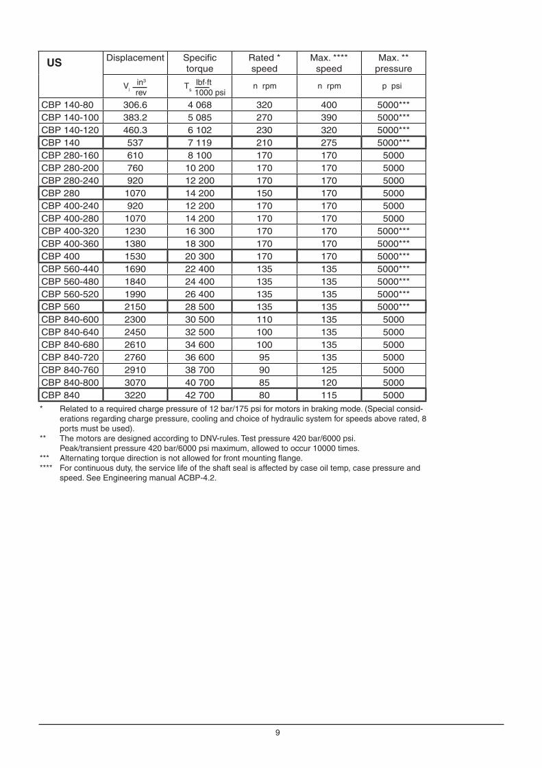
Compact CBP 140
FrontCompact CBP 280, 400
Centre
Front Compact CBP 560, 840
Centre
Alternative mounting flange
Through hole ø 110 (4.33)
Through holeø 170 (6.69)
Alternative mounting flange
Alternative mounting flange
Through hole ø 170 (6.69)
AC
B
D
E
Rotating part
C
B
D
E
Rotating part
A
C
B
D
E
Rotating part
C
B
D
E
Rotating part
CBP 280, CBP 400 CBP 400 only
CBP 560, CBP 840CBP 560 only

14
DimensionsInstallation dimensions and material for driven shaft
SplineThe splines shall be lubricated, either oiled with hydraulic oil at assembly, or filled with transmission oil from the connected gearbox. To avoid wear in the splines, the installation must be within the specified tolerances in figure. For control of spline, see table.
When splines are used for torque arm mounting, the spline shall be lubricated with oil at assembly. For production of shaft see, 078 0150, 078 0162, 078 0163, 278 5023, 278 5024, 278 5025 and 278 5026.
Flangemounting
Øi
Ø
Di
Dy
t
R1 (2x)
0,15 A
0,2 A
A
Bidirectional drives
Unidirectional drives
Steel with yield strength Relmin = 450 N/mm2
Steel with yield strength Relmin = 700 N/mm2
* O-ring to be used in submerged applications, or for external lubrication of the splines.
Motor CBP 140
CBP 280/400
CBP 560/840
Tooth profile and bottom form
DIN 5480 DIN 5480 DIN 5480
Tolerance 8f 8f 8f
GuideFlank
centringFlank
centringFlank
centring
Pressure angle 30° 30° 30°
Module 5 5 5
Number of teeth
22 38 50
Pitch diameter Ø 110 Ø 190 Ø 250
Minor diameter Ø 109 Ø 188 Ø 248
Major diameter Ø 119 Ø 199 Ø 259
Measure over measuring pins 129.781 210.158 270.307
Diameter of measuring pins
Ø 10 Ø 10 Ø 10
Addendum modification X M
+2.25 +2.25 +2.25
-0.083
-0.147
0
-0.220
0
-0.870
-0.103
-0.181
0
-0.320
0
-1.201
-0.088
-0.157
0
-0.290
0
-1.201
Øi Dy Di t O-ring*
CBP 140 510 ø529 ø515 4.4±0.1 2152 2115-566
CBP 280/400 600 ø714 ø700 4.4±0.1 2152 2115-743
CBP 560/840 800 ø820 ø806 4.4±0.1 2152 2115-793
+0.1 0
+0.20+0.05
+0.20+0.05

15
Dim CBP 280 CBP 400 CBP 560/840
Ammin
1807.0866
2007.8740
26010.2362
Bmmin
1064.17
1174.61
1536.02
Cmmin
1746.85
1947.64
25410
�A
30°
6±0,5(0,24±0,02)
Max. R 3,2a
�C
�A
30°
Max. R 3,2
6±0,5
B±0,5
(B±0,02)
(0,24±0,02)R 50(R 1,97)
a
Note: The dimensions are valid for +20 °C (68 °F)
Design of driven shaft end on heavily loaded shaft.
Where the driven shaft is heavily loaded and is sub-ject to high stresses, for example for changes in the direction of rotation and/or load, it is recommended that the driven shaft should have a stress relieving groove; see figure below and tables.
Normally loaded shaft
In drives with only one direction of rotation and/or load where the stresses in the shaft are moderate, the shaft can be plain, see figure and tables.
Bidirectional drives
Unidirectional drives
Steel with yield strength Relmin = 450 N/mm2
Steel with yield strength Relmin = 700 N/mm2
DimensionsWith hollow shaft, shaft coupling.
-0.014 -0.054
-0.00055 -0.00215
-0.015 -0.061
-0.00059 -0.00240
-0.017 -0.069
-0.00067 -0.00272
CBP 280 - 840
DEFG
M20>17 (0.67)25 (0.98)50 (1.97)
UNC 5/8">13.5 (0.53)22 (0.87)30 (1.18)
16
x
10
��± °25x = ±2 mm (0.079) misalignment in installation. x ≤ ±15 mm (0.59) movement when in use.
Note: Ideal angle = 0°
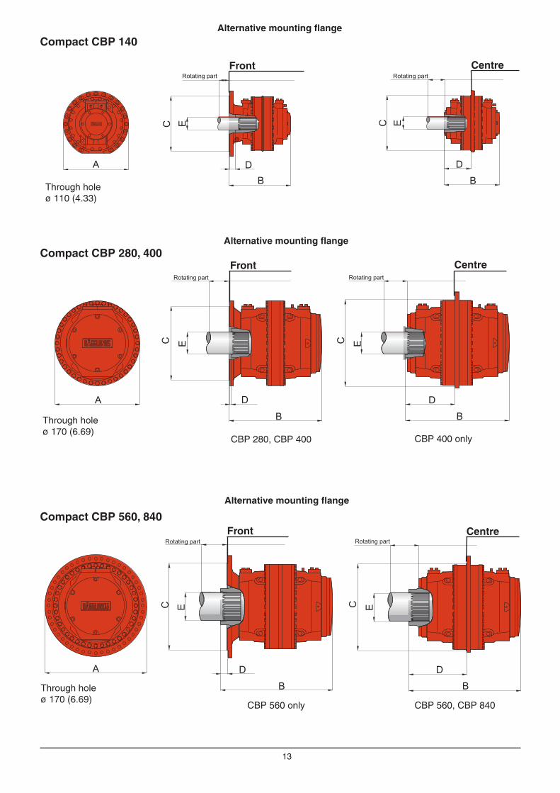
AccessoriesTorque arm, type TCAEasy to apply - Hägglunds torque arms.A shaft mounted gearless drive is achieved by utilizing the standard Hägglunds torque arm. As a result, alignment problems, expensive flexible couplings and bed plates are eliminated (see figure below).For CBP 140/280/400/560 front flange is recommended to be used, to reduce load on splines.
To be used with the Compact CBP motor.
Compact CBP motor
Torque arm
Shaft on driven machine
Torque arm Max torque (Nm) For alternating or pulsating torque
Max torque (lbf·ft) For alternating or pulsating torque
Max torque (Nm)At static torque
Max torque (lbf·ft) At static torque
TCA 14for CBP 140
70 000 51 600 84 000 62 000
TCA 40 for CBP 280/CBP 400
140 000 103 200 170 000 125 300
TCA 84 for CBP 400*/CBP 560/
CBP 840294 000 216 700 350 000 258 000
A
Torque arm
A
mm in
TCA 14 800 31.50
TCA 40 1250 49.21
TCA 84 1500 59.06
* For CBP 400 with centre mounting

17
Double ended torque arm, type DTCA 140The double ended torque arm is designed for CBP 140 (not reduced displacement), to eliminate external forces from the torque arm.Double ended torque arm, including double acting hydraulic cylinder and pivoted attachment. Following are included in delivery:
- Screws and washers (motor-torque arm)- Hose kit + clamps- Hose flange connections
Torque arm A mm (in)
Bmm (in)
Weightkg (lb)
DTCA 140 1165 (45.9) 780 (30.7) 155 (341)
Double ended torque arm, DTCB 40 - DTCB 84Double ended torque arm, including double acting hydraulic cylinder and pivoted attachment.Following are included in delivery:
- Screws and washers (motor-torque arm)- Hose kit + clamps- Hose flange connections
B
A
A
B
A
B
C
A
B
A
Motor Tandem motor
Torque arm
Motor type Ordering code
Tandem motor type Ordering code
A mm (in)
Bmm (in)
Weightkg (lb)
DTCB 40
CBP 280 F 078 1476-812 CBP280 F + TBP 14 + CBP140 078 1476-814
2120 (83.46)
900 (35.43)
335 (739)
CBP 280-240 F 078 1476-811 CBP400 F + TBP 14 + CBP140
CBP 400 F 078 1476-814
CBP 400-360 F 078 1476-813
CBP 400-320 F 078 1476-812
CBP 400-280 F
CBP 400-240 F 078 1476-811
DTCB 84
CBP 400 C 078 1476-805 CBP400 C + TBP 14 + CBP140 078 1476-805
3000 (118.11)
500 (1102)
CBP 400-360 C 078 1476-810 CBP560 F + TBP 14 + CBP140 078 1476-808
CBP 400-320 C CBP560 C + TBP 14 + CBP140
CBP 400-280 C CBP840 C + TBP 14 + CBP140 078 1476-809
CBP 400-240 C CBP840 C + TBP 21 + CA210 S28
CBP 560 F/C 078 1476-806 CBP560 C + TBP 40 + CBP280 078 1476-808
CBP 560-520 F/C CBP560 C + TBP 40 + CBP400 078 1476-809
CBP 560-480 F/C 078 1476-805
CBP 560-440 F/C
CBP 840 C 078 1476-809
CBP 840-800 C
CBP 840-760 C 078 1476-808
CBP 840-720 C
CBP 840-680 C
CBP 840-640 C
CBP 840-600 C 078 1476-807
F = Front C = Centre

18
Mounting set SMCB1 for speed encoder
Speed encoder kit for Compact CBP 140 motors where the speed encoder is enclosed and well protected.
The mounting set can be used for both spline and shaft coupling motors.
The encoder is used for detection of speed by pulse- frequency or/either direction of rotation by pulse-train.
The speed encoder kit is also available in a explo-sion proof version, please see Engineering Manual ACBP-3.4.1.
CBP 140 with SMCB1
CBP 560 with SMCB1

19
Shaft coupling set CBP 140 078 0693-804Shaft coupling set CBP 280 078 0693-803Shaft coupling set CBP 400 078 0693-802Shaft coupling set CBP 560/840 078 0693-801
Ordering Code
The set includes shaft coupling and shaft adapter. Mounting set must be ordered separately.The kit is designed for shaft, that can not be made with splines.
Shaft coupling set, CBP 140-840
O-ring delivered with the motor.
Motor Amm(in)
Bmm(in)
Dmm(in)
Weightkg(lb)
CBP 140 94(3.7)
394(15.51)
140(5.5)
84(185)
CBP 280 161(6.3)
N/A 180(7.1)
134(295)
CBP 400 183(7.2)
651(25.6)
200(7.9)
160(353)
CBP 560 315(12.4)
783(30.8)
260(10.2)
277(611)
CBP 840 N/A 783(30.8)
260(10.2)
277(611)
A
B
D
Mounting set(must be ordered separately)
Shaft coupling
Shaft adapter

20
WEIGHT
kg
S-890 42 MellanselHÄGGLUNDS DRIVES AB
SW
ED
EN
+46 660-871 60
+46 660-870 00
Telefax
http://www.hagglunds.com
Telephone
MAX PRESSURE
bar
HAGGLUNDSTYPE
INDIVID NO.
A
B CD
Compact Tandem MotorsA Tandem motor consists of 3 major units, Front motor + Tandem kit TBP xx + Rear motor. The Tandem kit (TBP 14/21/40) shall always be chosen according to the rear Standard spline motor. On the stamping sign on the Tandem kit, are the max pressure and the total weight for the complete unit declared. Note that the complete Ordering code for a Tandem motor, contains of 3 individual Ordering codes (3 parts).
Example:CBP 560 XXX SB0XHXC 00 + TBP 40 X 00 + CBP 400 XXX SX0XXXF 00 00
Stamping for TBP-unit
A: TA-type, same as Ordering codeB: Week of assembly (yy-ww)C: Max working pressure for the assembly D: Total weight of the assembly
CBP 560 XXX SB0XHXC 00 00 CBP 400 XXX SX0XXXF 00 00
Stamping plate
TBP 40 0 0 00
TBP 40 H 0 00
A
B
Tandem motorMax. pres-sure bar (psi)
Total weightkg (lb)
ALength mm (in)
BDiameter mm (in)
Max. torque to driven shaft*Nm (lbf·ft)
CBP280 F + TBP 14 + CBP140 350 (5000) 2080 (4586) 1387 (54.6)782 (30.8)
147 000 (108 422)
CBP400 F + TBP 14 + CBP140 350 (5000) 2430 (5357) 1505 (59.3)189 000 (139 399)
CBP400 C + TBP 14 + CBP140 350 (5000) 2380 (5247) 1494 (58.8)
940 (37.0)
CBP560 F + TBP 14 + CBP140 350 (5000) 2500 (5512) 1505 (59.3)245 000 (180 703)
CBP560 C + TBP 14 + CBP140 350 (5000) 2400 (5291) 1571 (61.9)
CBP840 C + TBP 14 + CBP140 350 (5000) 2670 (5886) 1689 (66.5) 343 000 (252 984)
CBP840 C + TBP 21 + CA210 S28 350 (5000) 2860 (6305) 1664 (65.5) 367 500 (271 054)
CBP560 C + TBP 40 + CBP280 350 (5000) 3690 (8135) 1929 (75.9) 294 000 (216 843)
CBP560 C + TBP 40 + CBP400 350 (5000) 4040 (8906) 2047 (80.6) 392 000 (289 124)

21
Diagrams for Compact CBP
Charge pressure - Compact CBP 140, 4-port connection
Charge pressure - Compact CBP 140, 8-port connection
Case 1: The motor works in braking mode. Required charge pressure at the inlet port is according to dia-gram above.
Case 2: The motor works in driving mode only. Required back pressure at the outlet port corresponds to 30% of value given in diagram above, but may not be lower than 2 bar (29 psi).
CB
P 14
0C
BP
140-
120
CBP 140
-100
CBP 140-
80
CB
P 14
0CBP
140-
120
CBP 140-
100
CBP 140-80

22
Charge pressure - Compact CBP 280-840, 8-port connection
Case 1: The motor works in braking mode. Required charge pressure at the inlet port is according to dia-gram above.
Case 2: The motor works in driving mode only. Required back pressure at the outlet port corresponds to 30% of value given in diagram above, but may not be lower than 2 bar (29 psi).
Charge pressure - Compact CBP 280-840, 4-port connection
CBP
840
-800
/840
-760
CBP
840
-720
CBP
840
CBP 560
/560
-520
CBP 280
CBP 560-480/560-440
CBP 400/400-360/280-240CBP 8
40-6
00
CBP 400-240/280-160
CBP 280-200/400-320/400-280
CBP
840
-680
/840
-640
0
2
4
6
8
10
12
14
16
18
20
0 10 20 30 40 50 60 70 80 90 100 110 120 130 140 150 160 170
Speed [rpm]
Rec
omm
ende
dch
arge
pres
sure
[bar
]
0
50
100
150
200
250
Rec
omm
ende
dch
arge
pres
sure
[psi
]
0
2
4
6
8
10
12
14
16
18
20
0 10 20 30 40 50 60 70 80 90 100 110 120 130 140 150 160 170
Speed [rpm]
Rec
omm
ende
dch
arge
pres
sure
[bar
]
0
50
100
150
200
250
Rec
omm
ende
dch
arge
pres
sure
[psi
]
CBP 400-240
CBP 280-240
CBP
840
-800
/840
-760
CBP
840
-720
CBP
840
CBP 560/560-520
CBP 280
CBP 560-480/560-460
CBP 400/400-360/280-200
CBP 840
-600
CBP 400-320/400-280/280-160
CBP 840
-680
/840
-640

23
0
20000
40000
60000
80000
100000
120000
140000
0
20
40
60
80
100
120
140
160
180
200
0 10 20 30 40 50 60 70 80 90 100 110 120 130
To
rqu
e[lbf*
ft]
To
rqu
e[k
Nm
]
Speed [rpm]
90 %91 %92 %93 %94 %
95 %
96 %
300 kW 500 kW 750 kW 1000 kW
0
20000
40000
60000
80000
100000
120000
140000
0
20
40
60
80
100
120
140
160
180
200
0 10 20 30 40 50 60 70 80 90 100 110 120 130
To
rqu
e[lb
f*ft
]
To
rqu
e[k
Nm
]
Speed [rpm]
90 %91 %92 %93 %94 %95 %96 %
500 kW 750 kW 1000 kW 1250 kW
0
20000
40000
60000
80000
100000
0
20
40
60
80
100
120
140
0 20 40 60 80 100 120 140 160
To
rqu
e[lb
f*ft
]
To
rqu
e[k
Nm
]
Speed [rpm]
90 %91 %92 %
93 %94 %
95 %96 %
500 kW 750 kW 1000 kW 1250 kW
0
20000
40000
60000
80000
100000
0
20
40
60
80
100
120
140
0 20 40 60 80 100 120 140 160
To
rqu
e[lbf*
ft]
To
rqu
e[k
Nm
]
Speed [rpm]
90 %91 %92 %93 %94 %
95 %
96 %
300 kW 500 kW 750 kW 1000 kW
0
10000
20000
30000
40000
50000
60000
70000
0
10
20
30
40
50
60
70
80
90
100
0 20 40 60 80 100 120 140 160
To
rqu
e[lbf*
ft]
To
rqu
e[k
Nm
]
Speed [rpm]
90 %91 %92 %93 %94 %95 %96 %
300 kW 500 kW 750 kW
0
10000
20000
30000
40000
50000
60000
70000
0
10
20
30
40
50
60
70
80
90
100
0 20 40 60 80 100 120 140 160
Torq
ue
[lbf*
ft]
Torq
ue
[kN
m]
Speed [rpm]
90 %91 %
92 %93 %94 %95 %
96 %
300 kW 500 kW 750 kW
0
5000
10000
15000
20000
25000
30000
35000
0
5
10
15
20
25
30
35
40
45
0 20 40 60 80 100 120 140 160 180 200
To
rqu
e(lb
f*ft
)
To
rqu
e(k
Nm
)
Speed (rpm)
96 % 95 % 94 % 93 %92 %
91 %
90 %
120 kW 200 kW 300 kW
0
5000
10000
15000
20000
25000
30000
35000
0
5
10
15
20
25
30
35
40
45
0 20 40 60 80 100 120 140 160 180 200
Torq
ue
(lbf*
ft)
Torq
ue
(kN
m)
Speed (rpm)
96 %
95 %
94 %
93 %
92 % 91 % 90 %
120 kW 200 kW 300 kW
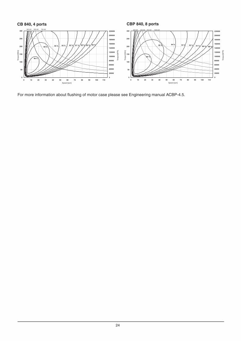
Overall efficiency, oil viscosity 40 cSt/187 SSU, Pc = 15 bar (217 psi)
CBP 140, 4 ports CBP 140, 8 ports
CBP 280, 4 ports CBP 280, 8 ports
CBP 400, 4 ports CBP 400, 8 ports
CBP 560, 4 ports CBP 560, 8 ports
24
CBP 840, 8 portsCB 840, 4 ports
0
20000
40000
60000
80000
100000
120000
140000
160000
180000
200000
220000
0
50
100
150
200
250
300
0 10 20 30 40 50 60 70 80 90 100 110
To
rqu
e[lbf*
ft]
To
rqu
e[k
Nm
]
Speed [rpm]
90 %91 %92 %93 %94 %95 %
96 %
300 kW 500 kW 750 kW
89 %
1000 kW
0
20000
40000
60000
80000
100000
120000
140000
160000
180000
200000
220000
0
50
100
150
200
250
300
0 10 20 30 40 50 60 70 80 90 100 110
To
rqu
e[lb
f*ft
]
To
rqu
e[k
Nm
]
Speed [rpm]
90 %91 %92 %93 %94 %95 %
300 kW 500 kW 750 kW
89 % 88 %
96 %
For more information about flushing of motor case please see Engineering manual ACBP-4.5.

25
Flushing of motor caseThe Compact CBP motors have very high total efficiency and are now frequently used in applications with high power. To avoid high temperature in the motor case, the losses generated in the motors must be cooled away, because high temperature gives lower viscosity and this gives reduction in rating life and maximum allowed power for the motor.
For continuous duty the motor case must be flushed when the power exceed the following maximum power:
Max power without flushingCBP 140/280 120 kW (160 hp) CBP 400/560/840 170 kW (227 hp)
Variation in volumetric loss at different oil viscosities for Compact motorsWhen calculating volumetric losses using other viscosities than 40 cSt/187 SSU, multiply the value given in the volumetric loss diagram by the factor K.
cSt4000
(40)- - -40150200
300
500
1000
2000
5000
10000
20000
100
10 20
0.5
10040 60
1.0
200
1.5
K
400 600 1000 n cSt
SSU
30002000
1000
500400300200150
100
30
75
50(187)
20
- - - - - - - -
Volumetric losses - Compact CBP motorsValid for an oil viscosity of 40 cSt/187 SSU.
CBP 140/400/560
0
5
10
15
20
25
0 50 100 150 200 250 300 350
High pressure [bar]
Vol
umte
riclo
sses
[lpm
]
0
1
2
3
4
5
6
0 1000 2000 3000 4000 5000
High pressure [psi]
Vol
umte
riclo
sses
[US
gpm
]
CBP 840
CBP 280

26
Diagrams for Compact CBP
Pressure loss, oil viscosity 40 cSt/187 SSU
CBP 400 pressure loss 4 ports
CBP 280 pressure loss 8 portsCBP 280 pressure loss 4 ports
CBP 140 pressure loss 4 ports CBP 140 pressure loss 8 ports
CBP 400 pressure loss 8 ports
CBP 560 pressure loss 4 ports CBP 560 pressure loss 8 ports
0
50
100
150
200
250
0
2
4
6
8
10
12
14
16
18
20
0 50 100 150 200 250 300 350 400
Pre
ssu
re lo
ss
[psi]
Pre
ssu
re lo
ss
[ba
r]
Speed [rpm]
CB
P140
CB
P140-1
20
CB
P140-1
00
CBP
140-
80
0
50
100
150
200
250
0
2
4
6
8
10
12
14
16
18
20
0 50 100 150 200 250 300 350 400
Pre
ssure
loss
[psi]
Pre
ssure
loss
[bar]
Speed [rpm]
CBP
140-
100
CBP
140-
120
CB
P140
CBP140-8
0
0
50
100
150
200
250
0
2
4
6
8
10
12
14
16
18
20
0 10 20 30 40 50 60 70 80 90 100 110 120 130 140 150 160 170
Pre
ssure
loss
[psi]
Pre
ssure
loss
[bar]
Speed [rpm]
CBP280
CBP280-240
CBP 280-200
CBP 280-160
0
2
4
6
8
10
12
14
16
18
20
0 10 20 30 40 50 60 70 80 90 100 110 120 130 140 150 160 170
Speed [rpm]
Re
co
mm
en
ded
ch
arg
ep
ressu
re[b
ar]
0
50
100
150
200
250
Re
co
mm
en
de
dch
arg
ep
ressu
re[p
si ]
CBP 280-160
CBP280
CBP 280-200
CBP280-240
0
50
100
150
200
250
0
2
4
6
8
10
12
14
16
18
20
0 10 20 30 40 50 60 70 80 90 100 110 120 130 140 150 160 170
Pre
ssure
loss
[psi]
Pre
ssure
loss
[bar]
Speed [rpm]
CBP400
CBP400-3
60
CBP 400-320
CBP 400-280
CBP 400-240
0
50
100
150
200
250
0
2
4
6
8
10
12
14
16
18
20
0 10 20 30 40 50 60 70 80 90 100 110 120 130 140 150 160 170
Pre
ssure
loss
[psi]
Pre
ssure
loss
[bar]
Speed [rpm]
CBP 400
CBP 400-360
CBP 400-320
CBP 400-280
CBP 400-240
0
50
100
150
200
250
0
2
4
6
8
10
12
14
16
18
20
0 10 20 30 40 50 60 70 80 90 100 110 120 130 140 150 160 170
Pre
ssure
loss
[psi]
Pre
ssure
loss
[bar]
Speed [rpm]
CBP
560
CBP
560-
520
CBP
560-
480
CBP560-4
40
0
50
100
150
200
250
0
2
4
6
8
10
12
14
16
18
20
0 10 20 30 40 50 60 70 80 90 100 110 120 130 140 150 160 170
Pre
ssure
loss
[psi]
Pre
ssure
loss
[bar]
Speed [rpm]
CBP560/560-520
CBP 560-480/560-440

27
CBP 840 pressure loss 4 ports CBP 840 pressure loss 8 ports
0
50
100
150
200
250
0
2
4
6
8
10
12
14
16
18
20
0 10 20 30 40 50 60 70 80 90 100 110 120 130 140 150 160 170
Pre
ssure
loss
[psi]
Pre
ssure
loss
[bar]
Speed [rpm]
CB
P840
CB
P840-8
00/8
40-7
60
CB
P84
0-68
0/84
0-64
0
CB
P84
0-72
0
CBP
840-
600
0
50
100
150
200
250
0
2
4
6
8
10
12
14
16
18
20
0 10 20 30 40 50 60 70 80 90 100 110 120 130 140 150 160 170
Pre
ssu
relo
ss
[psi]
Pre
ssu
relo
ss
[ba
r]
Speed [rpm]
CBP
840-600
CBP
840-
680/
840-
640
CBP
840-
720
CBP
840-
800/
840-
760
CBP
840

28
Versatile mounting - examples of installations
Torque arm mounted motor with splines.
Torque arm mounted motor with shaft coupling.
Flange mounted motor with spline and through hole for cooling of driven machine.
Bracket mounted motor with flange adapter.
Bracket mounted motor with stub shaft.
Flange mounted motor with splines and high radial load Fr on driven shaft.
Flange mounted motor with splines and low radial load from driven shaft.
Fr

29
Choice of hydraulic fluid
The Hägglunds hydraulic motors are primarily designed to operate on conventional petroleum based hydraulic oils. The hydraulic oil can be chosen in consultation with the oil supplier or your local sales office, bearing the following requirements in mind:
GeneralThe oil shall have FZG (90) fail stage minimum 11 described in IP 334 (DIN 51354). The oil must also contain inhibitors to prevent oxidation, corrosion and foaming. The viscosity of mineral oil is highly dependent of the temperature. The final choice of oil must depend on the operating temperature that can be expected or that has been established in the system and not in the hydraulic tank. High temperatures in the system greatly reduce the service life of oil and rubber seals, as well as resulting in low viscosity, which in turn provides poor lubrication. Content of water shall be less than 0.1%. In industrial applications with high demands for service life, the content of water shall be less than 0.05%.
Fire resistant fluidThe following fluids are tested for Hägglunds motors (ISO/DP 6071).
Fluid Approved Internal paint
HFA: Oil (3-5%) in water emulsion No -
HFB: Inverted emulsion 40-45% water in oil Yes Not painted*
HFC: Water-glycol Yes Not painted*
HFD synthetic fluids
HFD:R - Phosphate esters Yes Not painted*
HFD:S - Chlorinated hydrocarbons Yes Not painted*
HFD:T - Mixture of the above Yes Not painted*
HFD:U - Other compositions Yes Not painted*
* Must be specified in the order.
RECOMMENDED VISCOSITY IN MOTOR CASE AT OPERATING TEMPERATURE
40-150 cSt/187-720 SSU.
Temperature limits
Normal operating temperature should be less than +50 °C (122 °F).When operating with synthetic fluids, temper-ature should be less than +65 °C (150 °F).
Viton seals -20 °C to +100 °C
Viton seals -4 °F to +212 °F
Minimum viscosity limits at operating temperature in motor case
CBP 140 motors type C (coated pistons and coated cam rollers)
10 cSt/ 59 SSU*
CBP 280-840 motors type C (coated pistons and coated cam rollers) up to 80 rpm
10 cSt/ 59 SSU*
CBP 280-840 motors type C (coated pistons and coated cam rollers) up to 170 rpm
30 cSt/ 142 SSU*
*Low viscosity gives reduced service life for the motors. Max permitted viscosity is 10000 cSt/48000 SSU Viscosity index = 100 is recommended. Viscosity index = 150 can be used for operation with large temperature dif-ference, however many hydraulic fluids with VI-improvers are subject to temporary and permanent reductions of the viscosity. Hägglunds recommendation is always to use the base oil viscosity when calculating the rated life and max allowed power. For heavy-duty applications we recommend synthetic oils.

30
Choice of hydraulic fluidDown rating of pressure data and basic rating lifeDown rating of pressure, for motors used in systems with fire resistant fluids, the maximum pressure for motor given on data sheet must be multiplied with following factors:
HFA-fluid not fit for useHFB-fluid 0.7 x maximum pressure for motorHFC-fluid 0.7 x maximum pressure for motorHFD-fluid 0.9 x maximum pressure for motor
Down rating of basic rating life, for motors used in systems with fire resistant fluids, the "expected basic rated life" must be multiplied with following factors:
HFA-fluid not fit for useHFB-fluid 0.26 x expected life with mineral oilHFC-fluid 0.24 x expected life with mineral oilHFD-fluid 0.80 x expected life with mineral oil
Filtration The oil in a hydraulic system must always be filtered and also new oil from your supplier has to be filtered when adding it to the system. The grade of filtration in a hydraulic system is a question of service life v.s. money spent on filtration.
In order to obtain stated service life it is important to follow our recommendations concerning contamina-tion level.
When choosing the filter it is important to consider the amount of dirt particles that the filter can absorb and still operate satisfactory. For that reason we recommend a filter with an indicator that gives a signal when it is time to change the filter cartridge.
Filtering recommendationsBefore start-up, check that the system is thoroughly cleaned.1. For industrial applications the contamination level should not exceed ISO 4406:1999 18/16/13
(NAS 1638, class 7).2. When filling the tank and motor case, we recommend the use of a filter with the grade of filtration β10=75.
Explanation of "Grade of Filtration"Grade of filtration β10=75 indicates the following:β10 means the size of particle ≥10 µm that will be removed by filtration.=75 means the grade of filtration of above mentioned size of particle. The grade of filtration is defined as number of particles in the oil before filtration in relation to number of particles in the oil after filtration.
Ex. Grade of filtration is β10=75.
Before the filtration the oil contains N number of particles ≥10 µm and after passing the filter once the oil
contains number of particles ≥10 µm.
This means that number of particles have been filtered (=98.6%).
N75
=74·N75
N75N
* Vegetable fluids give good lubrication and small change of viscosity with different temperature. Vegetable fluids must be controlled every 3 months and temperature shall be less than +45 °C (113 °F) to give good service life for the fluid.
** Environmentally acceptable fluid give the same service life for the drive, as mineral oil.
Environmentally acceptable fluids
Fluid Approved Internal paint
Vegetable */** Fluid HTG Yes -
Synthetic ** Esters HE Yes -

31
Declaration of Conformity
Example of the Declaration of Conformity given by Hägglunds Drives AB
The Declaration of Conformity above, is available on request for deliveries from Hägglunds Drives AB. Translations into other languages are also available.
The partly completed machinery may only be put into operation when it has been established that the machine into which the partly completed machinery is to be incorporated conforms to the provisions of EC Machinery Directive 2006/42/EC, where relevant according to this directive.
The requirements are fulfi lled provided that the data in the product documentation (fi tting instructions, operat-ing instructions, project management and confi guration documents) are implemented by the product user. The requirements of Appendix I to Machinery Directive 2006/42/EC not mentioned here are not applied and have no relevance for the product.
The individual below is authorized to compile the relevant technical fi les:
Name: Björn Leidelöf Address: Hägglunds Drives AB, S-890 42 Mellansel
Mellansel, 2009-12-29
General principle no. 1.
1.1.3 1.1.5 1.2.1 1.3.1 1.3.2 1.3.3 1.3.4 1.3.6 1.3.7 1.5.3
1.5.4 1.5.5 1.5.6 1.5.8 1.5.13 1.6.1 1.6.3 1.7.2 1.7.3 1.7.4
Name: Compact CBPFunction: Hydraulic motorModel: CompactType: CBPTrade name: Compact CBP
satisfi es the following essential requirements of Machinery Directive 2006/42/EC in accordance with the chapter numbers in Appendix I:
It is also declared that the special technical documents for this partly completed machinery have been compiled in accordance with Appendix VII, Part B. These are trans-ferred on request to the market surveillance body in paper-based/electronic format.
Conformity with the provisions of further EU Directives, Standards or Specifi cations:
SS-EN 982SS-EN ISO 12100-1SS-EN ISO 12100-2
We reserve the right to make changes to the content of the Declaration of Incorporation. Current issue on request.
Declaration of Incorporation of partly completed machinery As defi ned by the EC Machinery Directive 2006/42/EC, Appendix II B
The manufacturer
Hägglunds Drives AB
hereby declares that the partly completed machinery

EN
834
-4h.
Rep
ro: Ö
viks
Rep
ro. P
rinte
r: Å
gren
s T
ryck
eri 2
011.
ww
w.hagglunds.com
Hägglunds Drives ABSE-890 42 Mellansel, SwedenTel: + 46 (0)660 870 00. E-mail: [email protected]
Our drive is your performance.