Embed Size (px)
Citation preview

Product Introduction
MX370107A Fading IQproducerTM
MG3700A Vector Signal Generator

Slide 1
MX370107A-E-L-1
For MG3700A Vector Signal Generator
MX370107A
Fading IQproducerTM
Product Introduction
ANRITSU CORPORATION
Version 4.00

Slide 2
MX370107A-E-L-1
Ordering Information Model/
Order No.Name
MG3700A Vector Signal Generator Required
MG3700A-002 Mechanical AttenuatorStandard Electron Attenuator is changed
into Mechanical Attenuator.
MG3700A-011 Upper Frequency 6 GHzStandard “250 kHz to 3 GHz” is extended
to “250 kHz to 6 GHz.”
MG3700A-021 ARB Memory Upgrade 512 M
sample
Standard “128 Msample/channel × 2” is
extended to “256 Msample/channel × 2.”
Recomme
ndation
MG3700A-031 High Speed BER Test FunctionStandard “1 kbps to 20 Mbps” is extended
to “100 bps to 120 Mbps.”
MX370107A Fading IQproducer Required
W2495AE MG3700A operation manual Booklet
W2496AEMG3700A IQproducer operation
manualBooklet
W2539AEMG3700A standard waveform
pattern operation manualBooklet
W2995AEMX370107A Fading IQproducer
operaton manualBooklet
J1261D Ethernet Cable (Shield Type) Cross, 3 mRecomme
ndation
Required when PC connected
directly to MG3700A by LAN.
Z0777Standard waveform pattern
upgrade kit
DVD set of pre-install wave form pattern of
latest version
G0141 HDD ASSY Exchange HDD when built-in HDD break.
J1277 IQ Output Conversion AdapterCable that converts IQ output connector
(D-sub) of mainframe into BNC
Recomme
ndation
Converts IQ output connector on
back of MG3700A from D-sub to
BNC.
Remarks
— Mainframe —
— Options —
Recomme
ndation
The PDF manual is on the software
CD. Order this when a booklet is
required.
— Softwares (License Key for IQproducer system) —
— Optional accessories —

Slide 3
MX370107A-E-L-1
What is Fading IQproducer?
The MX370107A Fading IQproducerTM is GUI-driven PC application software to
set fading parameters and generate waveform patterns by reading waveform
patterns for the MG3700A.
The generated waveform patterns are downloaded to the MG3700A and used
to output fading baseband signals and RF signals using the MG3700A ARB
generation function.
MG3700A
Vector Signal Generator
100Base-TX LAN
PC CF Card
(2) Waveform data
generated using
IQproducer
(3) Waveform data
transferred to
MG3700A
(4) Signal output (1) IQproducer
installed in PC
IQproducer
MX370107A
license key*
required
Waveform Pattern
IQ Data (ASCII)
*: Install the license key file in the main frame when adding a system license to a shipped
unit. The MG3700A main frame does not require return to the factory.

Slide 4
MX370107A-E-L-1
What is Fading IQproducer?
- Generating waveform patterns using MX3701xxA
=> The main frame requires a license.
The unlicensed software will run on the PC to test waveform pattern generation
but an unlicensed MG3700A cannot output signals because it does not
recognize the waveform patterns.
- Generating waveform patterns using EDA Tools (C, MATLAB, Microwave
Office) => Free license
The MX370107A supports the processes
inside the dotted line of the block diagram on
the right (fading of each IQ channel,
calculation of correlation line, AWGN
combination). [A]
Either waveform patterns created by another
IQproducer or IQ data (ASCII) created by
general simulation tools can be selected as
the input data file. [B]
Pattern File for MG3700A
or
IQ Data (ASCII format)
Fading of Each Channel
Calculation of
Correlation Line
AWGN Combination
IQ Data for Each Rx
IQ Data for each Tx
[A]
[B]

Slide 5
MX370107A-E-L-1
What is Fading IQproducer?
Fading IQproducer supports testing of Rx characteristics in a fading environment.
MG3700A
Tra
nsm
itter
Tx Antenna 1
Tx Antenna 2
Re
ce
ive
r
Rx Antenna 1
Rx Antenna 2
Re
ce
ive
r
Rx Antenna 1
Rx Antenna 2 MG3700A
IQ Data for
Tx Antenna 1
IQ Data for
Tx Antenna 2
IQ Data for
Rx Antenna 1
IQ Data for
Rx Antenna 2
MX370107A
Fading IQproducer
Fading
Evaluation of Fading Environment using
MG3700A (2x2 MIMO Example)
Slide 6
MX370107A-E-L-1
What is Fading IQproducer? Channel Configuration
1x1 SISO
1x2 SIMO
1x3 SIMO
1x4 SIMO
2x1 MISO
2x2 MIMO
2x3 MIMO
2x4 MIMO
3x1 MISO
3x2 MIMO
3x3 MIMO
3x4 MIMO
4x1 MISO
4x2 MIMO
4x3 MIMO
4x4 MIMO
1x1 SISO
2x2 MIMO
4x4 MIMO

Slide 7
MX370107A-E-L-1
What is Fading IQproducer? Fading Profile
System Channel ModelRural Area 6tap, Rural Area 4tap, Hilly Terrain 12 tap-1, Hilly Terrain 12 tap-2, Hilly Trrain 6 tap-1, Hilly Trrain 6 tap-2,
Urban Area 12 tap-1, Urban Area 12 tap-2, Urban Area 6 tap-1, Urban Area 6 tap-2, Equalisation Test 6 tap, Typical small cell 2 tap
W-CDMA (MS) Case1, Case2, Case3, Case4, Case5, Case6, Moving propagation, Birth-Death propagation, High Speed Train
W-CDMA (BS) Case1, Case2, Case3, Case4, Moving propagation, Birth-Death propagation, High Speed Train
HSDPA Case1, Case2, Case3, Case4, Case5, Case6, Case8, ITU Pedestrian A, ITU Pedestrian B, ITU Vehicular A
HSUPA Case1, Case2, Case3, Case4, ITU Pedestrian A, ITU Pedestrian B, ITU Vehicular A
CDMA2000 (MS) Case1, Case2, Case3, Case4, Case5, Case6
CDMA2000 (BS) Case1, Case2, Case3, Case4
TD-SCDMA Case1, Case2, Case3, ITU Pedestrian A, ITU Pedestrian B, ITU Vehicular A
1xEV-DO Configuration1, Configuration2, Configuration3, Configuration4, Configuration5
WLAN Model A, Model B, Model C, Model D, Model E
Mobile WiMAX ITU Pedestrian B, ITU Vehicular A, Large delay spread
MIMO Mobile
WiMAX
2x2 MIMO(ITU Pedestrian B, ITU Vehicular A, Large delay spread)
DVB-T Typical Urban (TU6), Typical Rural Area (RA6)
LTE (MS) EPA 5Hz, EVA 5Hz, EVA 70Hz, ETU 70Hz, ETU 300Hz, High Speed Train
LTE (BS) EPA 5Hz, EVA 5Hz, EVA 70Hz, ETU 70Hz, ETU 300Hz, High Speed Train
MIMO LTE 1x2 SIMO(EPA 5Hz, EVA 5Hz, EVA 70Hz, ETU 70Hz, ETU 300Hz), 2x2 MIMO(EPA 5Hz, EVA 5Hz, EVA 70Hz, ETU 70Hz, ETU 300Hz),
4x2 MIMO(EPA 5Hz, EVA 5Hz, EVA 70Hz, ETU 70Hz, ETU 300Hz), 4x4 MIMO(EPA 5Hz, EVA 5Hz, EVA 70Hz, ETU 70Hz, ETU 300Hz)
GSM

Slide 8
MX370107A-E-L-1
2x2MIMO Connection Example
Using EXT-Trigger
Using Master/Slave
MG3700A (Master) R
ece
ive
r Rx Antenna 1
Rx Antenna 2 MG3700A (Slave)
10 MHz
Reference
Trigger (= Pattern Sync Marker)
MG3700A
Re
ce
ive
r
Rx Antenna 1
Rx Antenna 2 MG3700A
PPG
10 MHz
Reference
TTL
Trigger <1 Sample Clock
Trigger
Output 1
Output 2
<1 Sample Clock
Trigger
Output 1
(Master)
Output 2
(Slave)

Slide 9
MX370107A-E-L-1
Operation Images
Setup Slide 10
Starting IQproducer Slide 11
IQproducer Main Screen Slide 11
Editing Parameters Slide 12–16
Generating Waveform Slide 17
Transferring Waveform Pattern Slide 18–19
Saving/Recalling Parameters Slide 20
Appendix: Parameter Setting Range Slide 21–24
Appendix: Example of Fading Characteristics Slide 25–30
Waveform Pattern Playback Time Slide 31-36
Time Required to Generate Waveform Patterns Slide 37-38

Slide 10
MX370107A-E-L-1
Setup
MG3700A Vector Signal Generator
MX370107A License key
100Base-TX LAN
Crossover cable
IQproducer
*Read the appended [LAN Connection] for the LAN
connection method between the PC and MG3700A.
*Read the appended [IQproducer Upgrade Procedure]
for the IQproducer installation method.
IQproducerTM Operating Environment
CPU Pentium III, 1 GHz or faster
Memory > 512 Mbytes
HDD > 5 Gbytes
Display > 1024 x 768 pixels
OS Windows2000(R) Professional,
Windows XP(R)
Connect the MG3700A and PC as shown below.
Install IQproducer in the PC.
Install the MX370107A license key in the MG3700A.

Slide 11
MX370107A-E-L-1
Starting IQproducer
Start IQproducer as follows: Start > Programs > Anritsu Corporation > IQproducer for MG3700A
When IQproducer starts, the following screen is displayed.
Choose Fading from the [System] pull-down menu.
IQproducer Main Screen

Slide 12
MX370107A-E-L-1
Editing Parameters: Common
The following screen is displayed by selecting Fading at [System]. Tx Antenna, Rx
Antenna, Channel, AWGN are set at the Common tab. Channel Configurations 1x1
SISO to 4x4 MIMO can be selected in Channel Configuration.
Channel Settings
Settings for Fading Profile of each channel, Moving Speed, and Doppler Frequency
Tx Antenna Settings
Settings for Tx signal:
Either MG3700A waveform
pattern or arbitrary IQ data
(ASCII) can be selected.
Rx Antenna Settings
Settings for AWGN combine:
Master or Slave can be
selected when there are two Rx
systems.
1x1 SISO
1x2 SIMO
1x3 SIMO
1x4 SIMO
2x1 MISO
2x2 MIMO
2x3 MIMO
2x4 MIMO
3x1 MISO
3x2 MIMO
3x3 MIMO
3x4 MIMO
4x1 MIMO
4x2 MIMO
4x3 MIMO
4x4 MIMO

Slide 13
MX370107A-E-L-1
Editing Parameters: Channel
Multi-path settings for each channel
Power Delay Profile
The state of each path is
displayed on the horizontal axis
(delay) and vertical axis
(power).
Multi-path Settings
The settings are listed in the
below table.
6 dB 3 dB 6 dB
Classical 6 dB Classical 3 dB Flat Rounded
Path 1 to 20
Fading Type Rayleigh, Rice, Constant
Delay 0.0000 to 2000.0000 us
Power -80.00 to 0.00 dB
Moving Speed 0.0 to 5000.0 km/h
Doppler Frequency 0.000 to Sampling Rate/2
Rician K factor -40.00 to 40.00 dB
Angle of Arrival 0.0 to 180.0 deg
Phase shift 0.0 to 359.9 deg
Spectrum Shape
Classical 6 dB,
Classical 3 dB,
Flat, Rounded
Correlation SettingEdit, Not Use,
Path number setting at Edit

Slide 14
MX370107A-E-L-1
Editing Parameters: Correlation Matrix Sheet Sets All Valid Paths. Using the diagonal components of the Correlation Matrix as the
border, the bottom-left element is set automatically so the top-right and bottom-left
elements form a complex conjugation.
Copy To All Paths:
Copies set Path parameter to
other All Valid Paths.
Select each element value:
When an element is selected,
the window shown below is
displayed to input numeric
values.
Save File…:
Saves Valid Path Correlation
Matrix parameters as .csv file.
Recall File…:
Loads .csv file to set
Correlation Matrix parameters.
Kronecker Method
Sets Kronecker Method ON
and OFF.
At ON, the Kronecker result of
multiplying the Tx Correlation
Matrix and Rx Correlation
Matrix is reflected in the
Correlation Matrix.
Slide 15
MX370107A-E-L-1
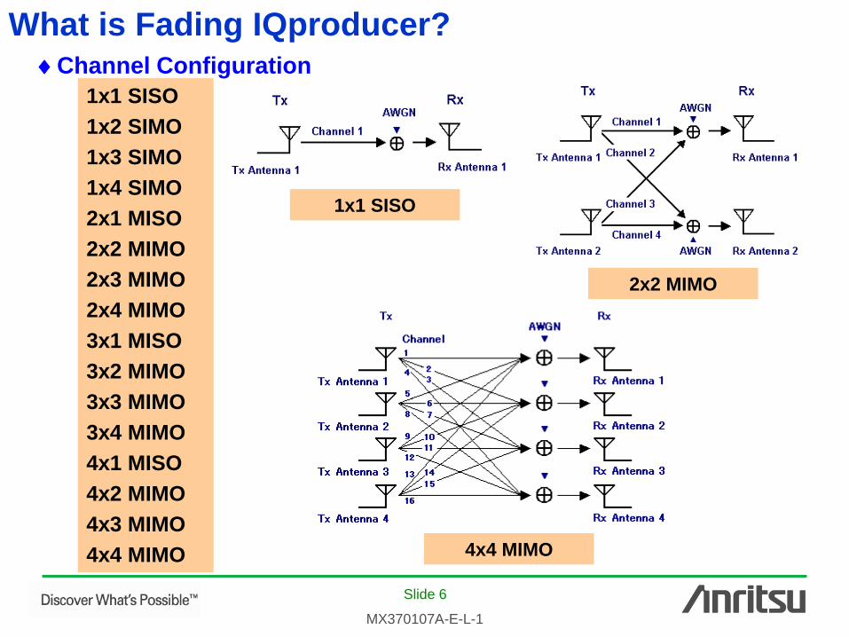
Editing Parameters: Moving Propagation
Moving Propagation can be set when
System Configuration = 1x1 SISO,
and Fading Profile = Moving Propagation (W-CDMA)
The setting items are listed in
the table below.
The delay of Path 2 to Path 1
changes according to the
expression.
Path 2
Power -80.00 to 0.00 dB
A (Offset) 0 to 500 us
B (Variation) 0 to 500 us
Omega 0.00 to 1.00 Hz

Slide 16
MX370107A-E-L-1
Editing Parameters: Birth-Death Propagation
Birth-Death Propagation can be set when
System Configuration = 1x1 SISO,
and Fading Profile = Birth-Death Propagation (W-CDMA)
The setting items are listed
in the table below.
The delay of Path 1 and Path 2
is switched at random.
The setting items are listed in
the table below.
Path 2
Power -80.00 to 0.00 dB
Maximum Delay 1 to 400 us
Delay Resolution 1 to Maximum Delay us
Dwell time 0.001 to 200.000 ms
Path Alternate
settingRandom, Sequence
Path 1, 2, Termination
Delay 0 to Maximum Delay
Slide 17
MX370107A-E-L-1
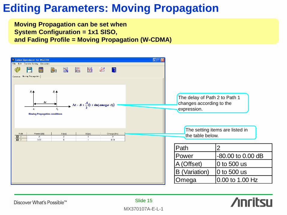
Generating Waveform: Calculation
Click the [Calculation] icon to start creation of the waveform pattern after setting
the parameters.
Name of waveform pattern file: 20 characters max.
Comment on MG3700A screen:
38 characters max. per line
Name of waveform pattern package: 31 characters max.
Generate the waveform pattern by clicking the [OK]
button.
Calculation: Creates waveform pattern Calculation: Creates waveform pattern
RMS Value Auto Setting: ON/OFF
RMS Value: 1 to 1634
File export destination folder

Slide 18
MX370107A-E-L-1
Transferring Waveform Pattern
Connect the MG3700A and PC via a LAN.
Transfer & Setting
Wizard
Input name or IP address of
MG3700A.
Connects to LAN
Transfer & Setting
Wizard
*Read the appended [LAN Connection] for the LAN
connection method between the PC and MG3700A.

Slide 19
MX370107A-E-L-1
Transferring Waveform Pattern
Select waveform
pattern saved on
MG3700A HDD.
Select when loading
waveform pattern into
memory at same time
as transferring.
Starts transfer

Slide 20
MX370107A-E-L-1
Saving/Recalling Parameters
Recall
Save
Recall
Save
The numerical values and settings for each item can be saved as a parameter file
for instant recall.
File Save Screen File Recall Screen

Slide 21
MX370107A-E-L-1
Appendix
MX370107A Fading IQproducer
Parameter Setting Range
Slide 22
MX370107A-E-L-1
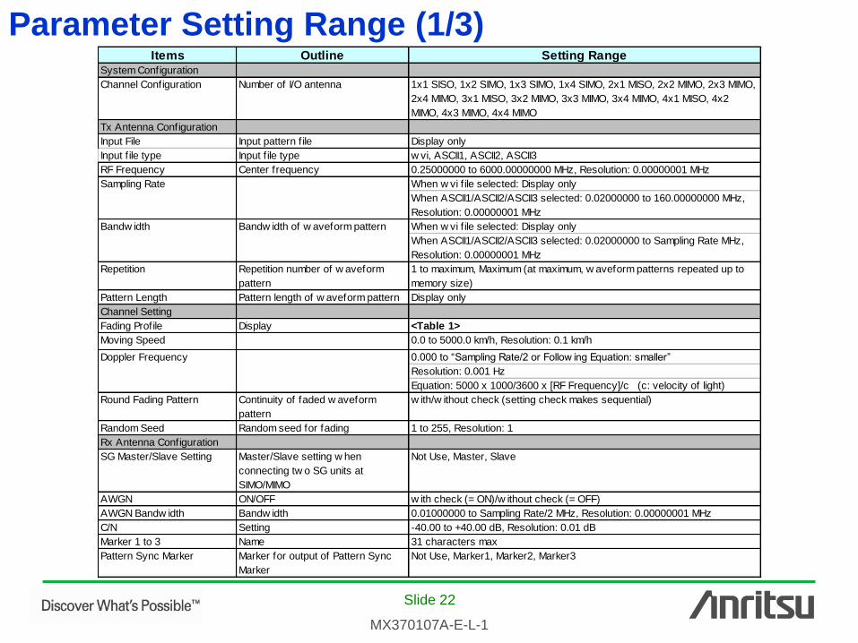
Parameter Setting Range (1/3) Items Outline Setting Range
System Configuration
Channel Configuration Number of I/O antenna 1x1 SISO, 1x2 SIMO, 1x3 SIMO, 1x4 SIMO, 2x1 MISO, 2x2 MIMO, 2x3 MIMO,
2x4 MIMO, 3x1 MISO, 3x2 MIMO, 3x3 MIMO, 3x4 MIMO, 4x1 MISO, 4x2
MIMO, 4x3 MIMO, 4x4 MIMO
Tx Antenna Configuration
Input File Input pattern f ile Display only
Input f ile type Input f ile type w vi, ASCII1, ASCII2, ASCII3
RF Frequency Center frequency 0.25000000 to 6000.00000000 MHz, Resolution: 0.00000001 MHz
When w vi f ile selected: Display only
When ASCII1/ASCII2/ASCII3 selected: 0.02000000 to 160.00000000 MHz,
Resolution: 0.00000001 MHz
When w vi f ile selected: Display only
When ASCII1/ASCII2/ASCII3 selected: 0.02000000 to Sampling Rate MHz,
Resolution: 0.00000001 MHz
Repetition Repetition number of w aveform
pattern
1 to maximum, Maximum (at maximum, w aveform patterns repeated up to
memory size)
Pattern Length Pattern length of w aveform pattern Display only
Channel Setting
Fading Profile Display <Table 1>
Moving Speed 0.0 to 5000.0 km/h, Resolution: 0.1 km/h
0.000 to “Sampling Rate/2 or Follow ing Equation: smaller”
Resolution: 0.001 Hz
Equation: 5000 x 1000/3600 x [RF Frequency]/c (c: velocity of light)
Round Fading Pattern Continuity of faded w aveform
pattern
w ith/w ithout check (setting check makes sequential)
Random Seed Random seed for fading 1 to 255, Resolution: 1
Rx Antenna Configuration
SG Master/Slave Setting Master/Slave setting w hen
connecting tw o SG units at
SIMO/MIMO
Not Use, Master, Slave
AWGN ON/OFF w ith check (= ON)/w ithout check (= OFF)
AWGN Bandw idth Bandw idth 0.01000000 to Sampling Rate/2 MHz, Resolution: 0.00000001 MHz
C/N Setting -40.00 to +40.00 dB, Resolution: 0.01 dB
Marker 1 to 3 Name 31 characters max
Pattern Sync Marker Marker for output of Pattern Sync
Marker
Not Use, Marker1, Marker2, Marker3
Sampling Rate
Bandw idth Bandw idth of w aveform pattern
Doppler Frequency

Slide 23
MX370107A-E-L-1
Parameter Setting Range (2/3) Items Outline Setting Range
Channel n parameters (n = 1 to 16)
Input File Display only
Fading Profile Display only
RF Frequency Center frequency Display only
Sampling Rate Display only
Bandw idth Bandw idth of w aveform pattern Display only
Pattern Length Pattern length of w aveform pattern Display only
Path (1 to 20)
Path Display of Path No., ON/OFF w ith check (= ON)/w ithout check (OFF)
Rayleigh, Rice, Constant
Rayleigh: Environment in w hich many scattering w aves arrive. The Rx level
is changed according to the Rayleigh distribution.
Rice: Environment in w hich many scattering and direct w aves arrive. The
Rx level is changed according to the Rice distribution.
Constant: Rx level not changed
Delay 0.0000 to 2000.0000 µs, Resolution: 0.0001 µs
Pow er Pow er of path 0.00 to –80.00 dB, Resolution: 0.01 dB
Moving Speed 0.0 to 5000.0 km/h, Resolution: 0.1 km/h
0.000 to Sampling Rate/2 or smaller, Resolution: 0.001 Hz
Equation: 5000 x 1000/3600 x [RF Frequency]/c (c: velocity of light)
–40.00 to 40.00 dB, Resolution: 0.01 dB
Set w hen Fading Type = Rice
0.0° to 180.0°, Resolution: 0.1°
Set w hen Fading Type = Rice
Phase Shift 0.0° to 359.9°, Resolution: 0.1°
Classical 6 dB, Classical 3 dB, Flat, Rounded
Cannot be set w hen Fading Type = Constant
Correlation Setting Setting correlation matrix Edit, Not Use, Path number setting at Edit
–1.0000 – j1.0000 to 1.0000 + j1.0000
Resolution: both real and imaginary parts = 0.0001
Set w hen Correlation Setting = Edit
Only top-right elements of opposite angle can be edited
Path Correlation Matrix
Angle of Arrival Direct w ave arrival angle
Spectrum Shape Doppler spectrum shape
Doppler Frequency
Rician K factor Pow er ratio betw een direct w ave
and scattering w ave
Fading Type Kinds of single path fading

Slide 24
MX370107A-E-L-1
Parameter Setting Range (3/3) Moving Propagation
Items Outline Setting RangePow er Pow er of Path 0.00 to –80.00 dB, Resolution: 0.01 dB
A (Offset) Offset of Path 2 0 to 500 µs, Resolution: 1
B (Variation) Change of delay at Path 2 0 to 500 µs, Resolution: 1
Omega Setting of Omega 0.00 to 1.00 Hz, Resolution: 0.01 Hz
Birth-Death propagation
Items Outline Setting RangePow er Pow er of path 0.00 to –80.00 dB, Resolution: 0.01 dB
Maximum Delay 1 to 400 µs, Resolution: “Delay Resolution”
Delay Resolution 1 to Maximum Delay µs, Resolution: 1
Dw ell Time 0.001 to 200.000 ms, Resolution: 0.001
Random, Sequence
Random: Path 1 and Path 2 sw itched randomly
Sequence: Delay and path sw itched by setting sequence
1, 2, Termination
Set w hen Path Alternate Setting = Sequence
0 to Maximum Delay
Enabled w hen Path Alternate = Sequence and previous element ≠
Termination
High Speed Train
Items Outline Setting RangeDs Setting of (the default value of the
distance betw een BS and train) x 2
0 to 2000 m, Resolution: 1 m
Dmin Setting of the distance betw een BS
and rail
1 to 100 m, Resolution: 1 m
-40.00 to 40.00 dB, Resolution: 0.01 dB
Moving Speed 0.0 to 5000.0 km/h, Resolution: 0.1 km/h
Maximum Doppler Frequency 0.000 to 2000.000 Hz, Resolution: 0.001 Hz
Delay Delay of path
Set w hen System Configuration = 1x1 SISO and Fading Profile = High Speed Train
Pow er ratio betw een direct w ave
and scattering w ave
Rician K factor
Path Alternate Setting
Path Path setting
Set w hen System Configuration = 1x1 SISO and Fading Profile = Moving Propagation
Set w hen System Configuration = 1x1 SISO and Fading Profile = Birth–Death Propagation
Slide 25
MX370107A-E-L-1
Appendix
MX370107A Fading IQproducer
Example of Fading Characteristics

Slide 26
MX370107A-E-L-1
Doppler Spectrum [Rayleigh]
Rayleigh with Classical 3 dB
Rayleigh with Classical 6 dB
Rayleigh with Flat
Rayleigh with Rounded
Slide 27
MX370107A-E-L-1
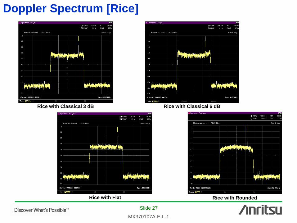
Doppler Spectrum [Rice]
Rice with Classical 3 dB Rice with Classical 6 dB
Rice with Flat Rice with Rounded

Slide 28
MX370107A-E-L-1
Cumulative Distribution and Level Crossing Rate (1/3)
0.01
0.1
1
10
100
-32.5 -30 -27.5 -25 -22.5 -20 -17.5 -15 -12.5 -10 -7.5 -5 -2.5 0 2.5 5 7.5
Peak Pow er / Avg Pow er (dB)
Pro
bability
(%
)
Rayleigh Distribution
Rayleigh Distribution(+2 dB shift)
Rayleigh Distribution(-2 dB shift)
Moving Speed = 583 (km/h)
1
10
100
1000
10000
-25.5 -23 -20.5 -18 -15.5 -13 -10.5 -8 -5.5 -3 -0.5 2 4.5
Peak Pow er / Avg Pow er (dB)
Level C
rossin
g R
ate
(tim
es/s
)
Rayleigh Distribution
Rayleigh Distribution (+20% shift)
Rayleigh Distribution (-20% shift)
Moving Speed = 583 (km/h)
Example: Calculated cumulative
distribution and level crossing rate
for following parameters
Cumulative Distribution (Moving Speed = 583 km/h)
Level Crossing Rate (Moving Speed = 583 km/h)
Channel Configuration 1x1 SISO
RF Frequency 2000.00000000 MHz
Sampling Rate 11.52 MHz
Repetition 1
Pattern Length 10220 ms
Moving Speed 2.3, 50, 120, 250, 583 km/h
Doppler Frequency 4.262, 92.657, 222.376,
463.283, 1080.377 Hz
Round Fading Pattern without check
Random Seed 1
AWGN without check
Rx Antenna Configuration (Rx Antenna 1)
System Configuration
Tx Antenna Configuration (Tx Antenna 1)
Channel Setting (Channel 1)

Slide 29
MX370107A-E-L-1
0.01
0.1
1
10
100
-32.5 -30 -27.5 -25 -22.5 -20 -17.5 -15 -12.5 -10 -7.5 -5 -2.5 0 2.5 5 7.5
Peak Pow er / Avg Pow er (dB)
Pro
bability
(%
)
Rayleigh Distribution
Rayleigh Distribution(+2 dB shift)
Rayleigh Distribution(-2 dB shift)
Moving Speed = 120 (km/h)
1
10
100
1000
-25.5 -23 -20.5 -18 -15.5 -13 -10.5 -8 -5.5 -3 -0.5 2 4.5
Peak Pow er / Avg Pow er (dB)
Level C
rossin
g R
ate
(tim
es/s
)
Rayleigh Distribution
Rayleigh Distribution (+20% shift)
Rayleigh Distribution (-20% shift)
Moving Speed = 120 (km/h)
Cumulative Distribution (Moving Speed = 120 km/h)
Level Crossing Rate (Moving Speed = 120 km/h)
Cumulative Distribution (Moving Speed = 250 km/h)
Level Crossing Rate (Moving Speed = 250 km/h)
0.01
0.1
1
10
100
-32.5 -30 -27.5 -25 -22.5 -20 -17.5 -15 -12.5 -10 -7.5 -5 -2.5 0 2.5 5 7.5
Peak Pow er / Avg Pow er (dB)
Pro
bability
(%
)
Rayleigh Distribution
Rayleigh Distribution(+2 dB shift)
Rayleigh Distribution(-2 dB shift)
Moving Speed = 250 (km/h)
1
10
100
1000
-25.5 -23 -20.5 -18 -15.5 -13 -10.5 -8 -5.5 -3 -0.5 2 4.5
Peak Pow er / Avg Pow er (dB)
Level C
rossin
g R
ate
(tim
es/s
)
Rayleigh Distribution
Rayleigh Distribution (+20% shift)
Rayleigh Distribution (-20% shift)
Moving Speed = 250 (km/h)
Cumulative Distribution and Level Crossing Rate (2/3)

Slide 30
MX370107A-E-L-1
0.01
0.1
1
10
100
-32.5 -30 -27.5 -25 -22.5 -20 -17.5 -15 -12.5 -10 -7.5 -5 -2.5 0 2.5 5 7.5
Peak Pow er / Avg Pow er (dB)
Pro
bability
(%
)
Rayleigh Distribution
Rayleigh Distribution(+2 dB shift)
Rayleigh Distribution(-2 dB shift)
Moving Speed = 50 (km/h)
1
10
100
1000
-25.5 -23 -20.5 -18 -15.5 -13 -10.5 -8 -5.5 -3 -0.5 2 4.5
Peak Pow er / Avg Pow er (dB)
Level C
rossin
g R
ate
(tim
es/s
)
Rayleigh Distribution
Rayleigh Distribution (+20% shift)
Rayleigh Distribution (-20% shift)
Moving Speed = 50 (km/h)
0.01
0.1
1
10
100
-32.5 -30 -27.5 -25 -22.5 -20 -17.5 -15 -12.5 -10 -7.5 -5 -2.5 0 2.5 5 7.5
Peak Pow er / Avg Pow er (dB)
Pro
bability
(%
)
Rayleigh Distribution
Rayleigh Distribution(+2 dB shift)
Rayleigh Distribution(-2 dB shift)
Moving Speed = 2.3 (km/h)
0.1
1
10
100
-25.5 -23 -20.5 -18 -15.5 -13 -10.5 -8 -5.5 -3 -0.5 2 4.5
Peak Pow er / Avg Pow er (dB)
Level C
rossin
g R
ate
(tim
es/s
)
Rayleigh Distribution
Rayleigh Distribution (+20% shift)
Rayleigh Distribution (-20% shift)
Moving Speed = 2.3 (km/h)
Cumulative Distribution (Moving Speed = 2.3 km/h)
Level Crossing Rate (Moving Speed = 2.3 km/h)
Cumulative Distribution (Moving Speed = 50 km/h)
Level Crossing Rate (Moving Speed = 50 km/h)
Cumulative Distribution and Level Crossing Rate (3/3)

Slide 31
MX370107A-E-L-1
Waveform Pattern Playback Time (1/6) The MG3700A has a built-in 256 Msample arbitrary waveform memory as standard,
plus a 512 Msample memory as an option. The waveform pattern playback time is
limited by the memory size. The following shows examples of replay times with
LTE(MS).
*These values are not guaranteed because the playback time depends on the conditions.
BW Sampling Rate
256MSample 512MSample
1.4M 3.84M 69.91 139.81
3.0M 7.68M 34.96 69.91
5.0M 15.36M 17.48 34.95
10.0M 30.72M 8.74 17.48
15.0M 30.72M 8.74 17.48
20.0M 61.44M 4.37 8.74
Maximum Playback Time[s]
UE Conformance testing (3GPP 36521-1-840)
Minimum Test time for PDSCH Single Antenna Port Performance
Minimum Test time for PDSCH Single Antenna Port Performance with 1 PRB
Minimum Test time for PDSCH Transmit diversity 2x2
Minimum Test time for PDSCH Transmit diversity 4x2
Minimum Test time for PDSCH Open Loop Spacial Multiplexing 2x2
Minimum Test time for PDSCH Open Loop Spacial Multiplexing 4x2
Minimum Test time for PDSCH Closed Loop Single/Multilayer Spacial Multiplexing 2x2
Minimum Test time for PDSCH Closed Loop Single/Multilayer Spacial Multiplexing 4x2

Slide 32
MX370107A-E-L-1
Without
Option21
(256 Msample)
Without Option21
(256 Msample)
With Option21
(512 Msample)
With Option21
(512 Msample)
1 R.2(10 MHz, full,
QPSK, 1/3)O ×
[1.1] (1x2 Low)
EVA,5O O
2 R.2(10 MHz, full,
QPSK, 1/3)O O
[1.2] (1x2 Low)
ETU,70O O
3 R.2(10 MHz, full,
QPSK, 1/3)O O
[1.3] (1x2 Low)
ETU,300O O
4 R.2(10 MHz , full,
QPSK, 1/3) O -
[1.4] (1x2 Low)
HSTO -
5 R.4(1.4 MHz, full,
QPSK, 1/3)O O
[2.1] (1x2 Low)
EVA,5O O
6 R.3(10 MHz, full,
16QAM, ½)× ×
[1.5] (1x2 Low)
EVA,5O O
7 R.3(10 MHz, full,
16QAM, ½)O O
[1.6] (1x2 Low)
ETU,70O O
7482
682
Test
number
Demodulation
scenario plain
text:
Minimum number
of
subframes(MNS)
to reach target +-
2%
Table G.3.5-1: Minimum Test time for PDSCH Single Antenna Port PerformanceMinimum number
of active
subframes
2000
174 2000
96 tbd
17789 19000
9041 11000
243 2000
9000
Without
Option21
(256 Msample)
Without Option21
(256 Msample)
With Option21
(512 Msample)
With Option21
(512 Msample)
8 R.3(10 MHz, full
64 QAM, 1/2) O O
[1.7] (1x2 High)
ETU,300O O
9 R.5(3 MHz, full,
64QAM, ¾) O O
[2.2] (1x2 Low)
EVA,5O O
10 R.6(5 MHz, full,
64QAM, 3/4)O ×
[2.3] (1x2 Low)
EVA,5O O
11 R.7(10 MHz, full,
64QAM, ¾)O O
[1.8] (1x2 Low)
EVA,5O O
12 R.7(10 MHz, full,
64QAM, ¾) O O
[1.9] (1x2 Low)
ETU,70O O
13 R.7(10 MHz, full,
64 QAM, 3/4)O ×
[1.10] (1x2High)
EVA,5O O
14 R.8(15 MHz, full,
64QAM, ¾)O O
[2.4] (1x2 Low)
EVA,5O O
Test
number
Demodulation
scenario plain
text:
Minimum number
of
subframes(MNS)
to reach target +-
2%
Table G.3.5-1: Minimum Test time for PDSCH Single Antenna Port PerformanceMinimum number
of active
subframes
1346 3000
28159 30000
17448 19000
3039 5000
896 2000
7697 9000
4919 6000
Waveform Pattern Playback Time (2/6)

Slide 33
MX370107A-E-L-1
Without
Option21
(256 Msample)
Without Option21
(256 Msample)
With Option21
(512 Msample)
With Option21
(512 Msample)
15 R.9(20 MHz, full,
64QAM, 3/4)× ×
[2.5] (1x2 Low)
EVA,5O O
16 R.0(3 MHz, 1PRB,
16QAM,1/2)O O
[3.1] (1x2 Low)
ETU,70O O
17 R.1(10 MHz,
1PRB, 16QAM, ½)O O
[3.2] (1x2 Low)
ETU,70O O
18 R.1(20 MHz,
1PRB, 16QAM, ½)× ×
[3.3] (1x2 Low)
ETU,70× ×
Test
number
Demodulation
scenario plain
text:
Minimum number
of
subframes(MNS)
to reach target +-
2%
Table G.3.5-1: Minimum Test time for PDSCH Single Antenna Port PerformanceMinimum number
of active
subframes
7000
2379 4000
2373 4000
9173 11000
5730
Table G.3.5-2: Minimum Test time for PDSCH Single Antenna Port Performance with 1 PRBWithout
Option21
(256 Msample)
Without Option21
(256 Msample)
With Option21
(512 Msample)
With Option21
(512 Msample)
1 R.29(10MHz,
1PRB, 16QAM, ½)
(1x2 Low)O O
[3.4] ETU,70
[MBFSN] O O
3779 5000
Test No Min No of active
subframes
Demod Scenario
(info)
Target,
Simulation
Table G.3.5-3: Minimum Test time for PDSCH Transmit diversity 2x2Without
Option21
(256 Msample)
Without Option21
(256 Msample)
With Option21
(512 Msample)
With Option21
(512 Msample)
1 R11(10MHz, full,
16QAM ½)
(2x2 Med)× ×
[7.1] EVA,5
[SFBC, Space
Frequency Block
Code]
O O
2 R.10(10MHz, Full,
QPSK, 1/3)
(2x2 low)O -
[7.2] HST
[SFBC] O -
16000
94 tbd
14321
Test No Min No of active
subframes
Demod Scenario
(info)
Target,
Simulation
Table G.3.5-4: Minimum Test time for PDSCH Transmit diversity 4x2Without
Option21
(256 Msample)
Without Option21
(256 Msample)
With Option21
(512 Msample)
With Option21
(512 Msample)
1 R.12(1.4MHz, full,
QPSK 1/3)
(4x2 med)
EPA,5
O O
[7.3] [SFBC-FSTD,
SFBC-Frequency
Shifted Transmit
Diversity]
O O
Test No Demod Scenario
(info)
Target,
Simulation
Min No of active
subframes
13449 15000
Waveform Pattern Playback Time (3/6)
Slide 34
MX370107A-E-L-1
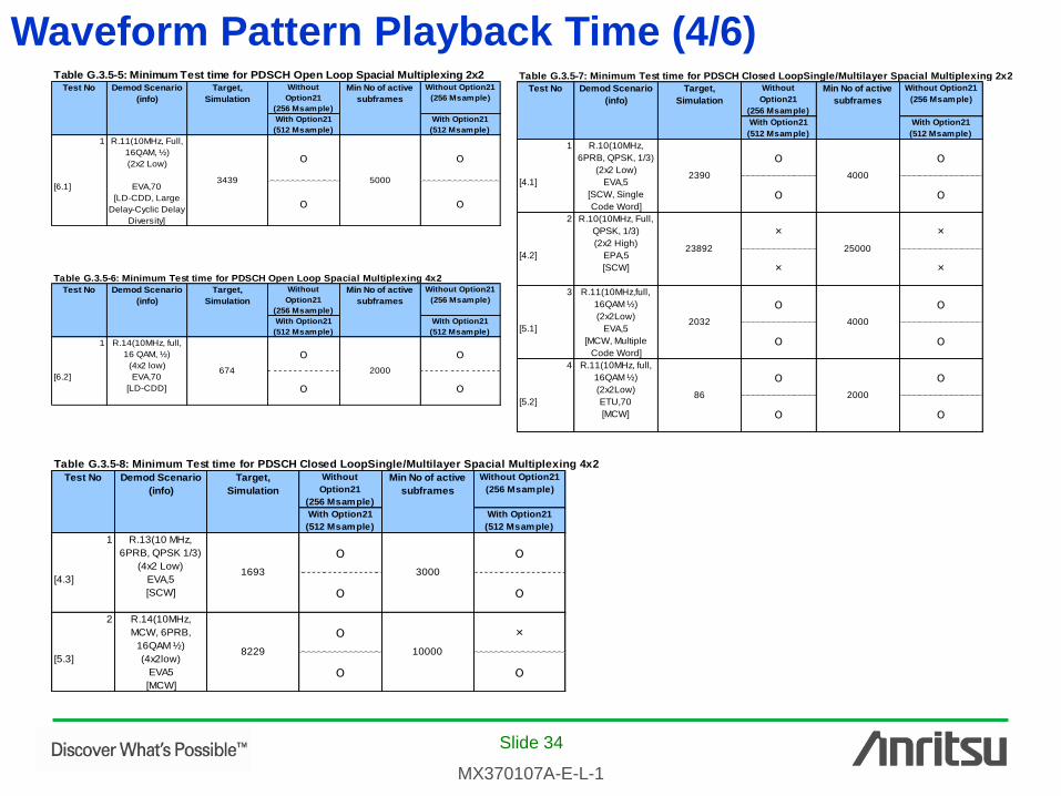
Table G.3.5-5: Minimum Test time for PDSCH Open Loop Spacial Multiplexing 2x2Without
Option21
(256 Msample)
Without Option21
(256 Msample)
With Option21
(512 Msample)
With Option21
(512 Msample)
1 R.11(10MHz, Full,
16QAM, ½)
(2x2 Low)O O
[6.1] EVA,70
[LD-CDD, Large
Delay-Cyclic Delay
Diversity]
O O
Test No Demod Scenario
(info)
Target,
Simulation
Min No of active
subframes
50003439
Without
Option21
(256 Msample)
Without Option21
(256 Msample)
With Option21
(512 Msample)
With Option21
(512 Msample)
1 R.14(10MHz, full,
16 QAM, ½)
(4x2 low)O O
[6.2] EVA,70
[LD-CDD] O O
Table G.3.5-6: Minimum Test time for PDSCH Open Loop Spacial Multiplexing 4x2
Min No of active
subframes
Test No Target,
Simulation
Demod Scenario
(info)
674 2000
Without
Option21
(256 Msample)
Without Option21
(256 Msample)
With Option21
(512 Msample)
With Option21
(512 Msample)
1 R.10(10MHz,
6PRB, QPSK, 1/3)
(2x2 Low)O O
[4.1] EVA,5
[SCW, Single
Code Word]O O
2 R.10(10MHz, Full,
QPSK, 1/3)
(2x2 High)
× ×
[4.2] EPA,5
[SCW] × ×
3 R.11(10MHz,full,
16QAM ½)
(2x2Low)O O
[5.1] EVA,5
[MCW, Multiple
Code Word]O O
4 R.11(10MHz, full,
16QAM ½)
(2x2Low)O O
[5.2] ETU,70
[MCW] O O
2390
23892
2032
86 2000
4000
25000
4000
Min No of active
subframes
Table G.3.5-7: Minimum Test time for PDSCH Closed LoopSingle/Multilayer Spacial Multiplexing 2x2
Target,
Simulation
Test No Demod Scenario
(info)
Without
Option21
(256 Msample)
Without Option21
(256 Msample)
With Option21
(512 Msample)
With Option21
(512 Msample)
1 R.13(10 MHz,
6PRB, QPSK 1/3)
(4x2 Low)O O
[4.3] EVA,5
[SCW] O O
2 R.14(10MHz,
MCW, 6PRB,
16QAM ½)O ×
[5.3] (4x2low)
EVA5
[MCW]O O
30001693
100008229
Min No of active
subframes
Table G.3.5-8: Minimum Test time for PDSCH Closed LoopSingle/Multilayer Spacial Multiplexing 4x2
Test No Demod Scenario
(info)
Target,
Simulation
Waveform Pattern Playback Time (4/6)
Slide 35
MX370107A-E-L-1
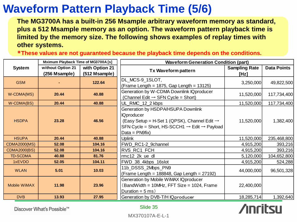
The MG3700A has a built-in 256 Msample arbitrary waveform memory as standard,
plus a 512 Msample memory as an option. The waveform pattern playback time is
limited by the memory size. The following shows examples of replay times with
other systems.
*These values are not guaranteed because the playback time depends on the conditions.
without Option 21 with Option 21 Data Points
(256 Msample) (512 Msample)
GSM - 122.64DL_MCS-9_1SLOT,
(Frame Length = 1875, Gap Length = 13125)3,250,000 49,822,500
W-CDMA(MS) 20.44 40.88Generation by W-CDMA Downlink IQproducer
(Channel Edit → SFN Cycle = Short)11,520,000 117,734,400
W-CDMA(BS) 20.44 40.88 UL_RMC_12_2 kbps 11,520,000 117,734,400
HSDPA 23.28 46.56
Generation by HSDPA/HSUPA Downlink
IQproducer
(Easy Setup = H-Set 1 (QPSK), Channel Edit →
SFN Cycle = Short, HS-SCCH1 → Edit → Payload
Data = PN9fix)
11,520,000 1,382,400
HSUPA 20.44 40.88 Uplink 11,520,000 235,468,800
CDMA2000(MS) 52.08 104.16 FWD_RC1-2_9channel 4,915,200 393,216
CDMA2000(BS) 52.08 104.16 RVS_RC1_FCH 4,915,200 393,216
TD-SCDMA 40.88 81.76 rmc12_2k_ue_dl 5,120,000 104,652,800
1xEVDO 52.05 104.11 FWD_38_4kbps_16slot 4,915,200 524,288
WLAN 5.01 10.0311b_DSSS_2Mbps_PN9
(Frame Length = 188848, Gap Length = 27192)44,000,000 96,501,328
Mobile WiMAX 11.98 23.96
Generation by Mobile WiMAX IQproducer
(BandWidth = 10MHz, FFT Size = 1024, Frame
Duration = 5 ms)
22,400,000
DVB 13.93 27.95 Generation by DVB-T/H IQproducer 18,285,714 1,392,640
Tx Waveform patternSampling Rate
[Hz]
Waveform Generation Condition (part)
System
Mximum Playback Time of MG3700A [s]
Waveform Pattern Playback Time (5/6)

Slide 36
MX370107A-E-L-1
Most 3GPP fading frequencies are 800
to 900 times.
The table on the right shows the
moving speed when the fading
frequency is 1000 times and does not
the exceed memory size.
The frequency becomes more than
1000 times when setting faster than
the moving speed in the table.
Doppler Frequency is directly
proportional to RF, and the size of the
waveform pattern file becomes small.
Comparison with W-CDMA 3GPP Specifications
*RF = 1 GHz
w ithout Option 21 w ith Option 21
(256 Msample) (512 Msample)
GSM - 8.8
W-CDMA (MS) 52.8 26.4
W-CDMA (BS) 52.8 26.4
HSDPA 42.9 21.5
HSUPA 52.8 26.4
CDMA2000 (MS) 20.7 10.4
CDMA2000 (BS) 20.7 10.4
TD-SCDMA 26.4 13.2
1xEVDO 20.7 10.4
WLAN 215.4 107.6
Mobile WiMAX 90.1 45
DVB 77.5 38.6
System
Minimum Moving Speed [km/h]
Waveform Pattern Playback Time (6/6)

Slide 37
MX370107A-E-L-1
Time Required to Generate Waveform Patterns (1/2)
The times required when generating waveforms using the following spectrum are
shown below.
Sometimes, the time is very long, However, generated patterns can be stored in the
MG3700A hard disk and quickly recalled.
PC Specification and Waveform
Generation Conditions
PC Specification and Waveform
Generation Conditions
CPU
Intel Core i7 2.67GHz
(number of processors: 4)
Memory 2.85GB
OS
Windows XP Professional
(32-bit operating system)
Pattern created with LTE IQproducer
FRC_R_14_FDD_0-3.wvd
RF = 2GHz
Bandwidth = 10MHz
FFT Size = 1024
Frame Duration = 10ms
Sampling Rate = 30.72 MHz
Repetition = Maximum
(Fading Profile)
MIMO LTE/4x4 MIMO/ETU 300Hz/High Correlation(9Path)
MIMO LTE/2x2 MIMO/ETU 300Hz/High Correlation(9Path)
LTE(MS)/ETU 300Hz(9Path)
Without Opt-21(256 Msamples)
Calc. Result Pattern Size (1GB×number of output patterns)
4x4MIMO 52 h 11 min
2x2MIMO 11 h 51 min
1x1SISO 2 h 58 min
Waveform
Pattern
Calc. Result Pattern Size (588MB×number of output patterns)
Path 1Path 6Path
1x2SIMO 47 min 2 h 25 min
1x4SIMO 1 h 32 min 4 h 59 min
CPU
Intel Core i7 2.67GHz
(number of processors: 4)
Memory 2.85GB
OS Windows XP Professional
Waveform
Pattern
ISDBT_2layer_movie2.wvd
RF = 500MHz
Sampling Rate = 16.25MHz
Bandwidth = 5.57MHz
Pattern Length = 9253.44ms
(Fading Profile)
DVB-T/Typical Urban(TU6) 30km/h
Without Opt-21(256 Msamples)
Slide 38
MX370107A-E-L-1
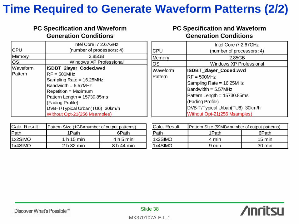
PC Specification and Waveform
Generation Conditions
PC Specification and Waveform
Generation Conditions
CPU
Intel Core i7 2.67GHz
(number of processors: 4)
Memory 2.85GB
OS Windows XP Professional
Waveform
Pattern
ISDBT_2layer_Coded.wvd
RF = 500MHz
Sampling Rate = 16.25MHz
Bandwidth = 5.57MHz
Repetition = Maximum
Pattern Length = 15730.85ms
(Fading Profile)
DVB-T/Typical Urban(TU6) 30km/h
Without Opt-21(256 Msamples)
CPU
Intel Core i7 2.67GHz
(number of processors: 4)
Memory 2.85GB
OS Windows XP Professional
Waveform
Pattern
ISDBT_2layer_Coded.wvd
RF = 500MHz
Sampling Rate = 16.25MHz
Bandwidth = 5.57MHz
Pattern Length = 15730.85ms
(Fading Profile)
DVB-T/Typical Urban(TU6) 30km/h
Without Opt-21(256 Msamples)
Calc. Result Pattern Size (1GB×number of output patterns)
Path 1Path 6Path
1x2SIMO 1 h 15 min 4 h 5 min
1x4SIMO 2 h 32 min 8 h 44 min
Calc. Result Pattern Size (59MB×number of output patterns)
Path 1Path 6Path
1x2SIMO 4 min 15 min
1x4SIMO 9 min 30 min
Time Required to Generate Waveform Patterns (2/2)

• United StatesAnritsu Company1155 East Collins Blvd., Suite 100, Richardson, TX 75081, U.S.A.Toll Free: 1-800-267-4878Phone: +1-972-644-1777Fax: +1-972-671-1877
• CanadaAnritsu Electronics Ltd.700 Silver Seven Road, Suite 120, Kanata, Ontario K2V 1C3, CanadaPhone: +1-613-591-2003 Fax: +1-613-591-1006
• Brazil Anritsu Eletrônica Ltda.Praça Amadeu Amaral, 27 - 1 Andar01327-010 - Bela Vista - São Paulo - SP - BrazilPhone: +55-11-3283-2511Fax: +55-11-3288-6940
• MexicoAnritsu Company, S.A. de C.V.Av. Ejército Nacional No. 579 Piso 9, Col. Granada11520 México, D.F., MéxicoPhone: +52-55-1101-2370Fax: +52-55-5254-3147
• United KingdomAnritsu EMEA Ltd.200 Capability Green, Luton, Bedfordshire, LU1 3LU, U.K.Phone: +44-1582-433200 Fax: +44-1582-731303
• FranceAnritsu S.A.12 avenue du Québec, Bâtiment Iris 1- Silic 612,91140 VILLEBON SUR YVETTE, FrancePhone: +33-1-60-92-15-50Fax: +33-1-64-46-10-65
• GermanyAnritsu GmbHNemetschek Haus, Konrad-Zuse-Platz 1 81829 München, Germany Phone: +49-89-442308-0 Fax: +49-89-442308-55
• ItalyAnritsu S.r.l.Via Elio Vittorini 129, 00144 Roma, ItalyPhone: +39-6-509-9711 Fax: +39-6-502-2425
• SwedenAnritsu ABBorgarfjordsgatan 13A, 164 40 KISTA, SwedenPhone: +46-8-534-707-00 Fax: +46-8-534-707-30
• FinlandAnritsu ABTeknobulevardi 3-5, FI-01530 VANTAA, FinlandPhone: +358-20-741-8100Fax: +358-20-741-8111
• DenmarkAnritsu A/S (Service Assurance)Anritsu AB (Test & Measurement)Kay Fiskers Plads 9, 2300 Copenhagen S, DenmarkPhone: +45-7211-2200Fax: +45-7211-2210
• RussiaAnritsu EMEA Ltd. Representation Office in RussiaTverskaya str. 16/2, bld. 1, 7th floor.Russia, 125009, MoscowPhone: +7-495-363-1694Fax: +7-495-935-8962
• United Arab EmiratesAnritsu EMEA Ltd.Dubai Liaison OfficeP O Box 500413 - Dubai Internet CityAl Thuraya Building, Tower 1, Suit 701, 7th FloorDubai, United Arab EmiratesPhone: +971-4-3670352Fax: +971-4-3688460
• IndiaAnritsu India Private Limited2nd & 3rd Floor, #837/1, Binnamangla 1st Stage, Indiranagar, 100ft Road, Bangalore - 560038, IndiaPhone: +91-80-4058-1300Fax: +91-80-4058-1301
• SingaporeAnritsu Pte. Ltd.60 Alexandra Terrace, #02-08, The Comtech (Lobby A)Singapore 118502Phone: +65-6282-2400Fax: +65-6282-2533
• P.R. China (Shanghai)Anritsu (China) Co., Ltd.Room 1715, Tower A CITY CENTER of Shanghai, No.100 Zunyi Road, Chang Ning District, Shanghai 200051, P.R. ChinaPhone: +86-21-6237-0898Fax: +86-21-6237-0899
• P.R. China (Hong Kong)Anritsu Company Ltd.Unit 1006-7, 10/F., Greenfield Tower, Concordia Plaza,No. 1 Science Museum Road, Tsim Sha Tsui East, Kowloon, Hong Kong, P.R. ChinaPhone: +852-2301-4980Fax: +852-2301-3545
• JapanAnritsu Corporation8-5, Tamura-cho, Atsugi-shi, Kanagawa, 243-0016 JapanPhone: +81-46-296-1221Fax: +81-46-296-1238
• KoreaAnritsu Corporation, Ltd.502, 5FL H-Square N B/D, 681Sampyeong-dong, Bundang-gu, Seongnam-si, Gyeonggi-do, 463-400 KoreaPhone: +82-31-696-7750Fax: +82-31-696-7751
• AustraliaAnritsu Pty. Ltd.Unit 21/270 Ferntree Gully Road, Notting Hill, Victoria 3168, AustraliaPhone: +61-3-9558-8177Fax: +61-3-9558-8255
• TaiwanAnritsu Company Inc.7F, No. 316, Sec. 1, NeiHu Rd., Taipei 114, TaiwanPhone: +886-2-8751-1816Fax: +886-2-8751-1817
Specifications are subject to change without notice.
1209
Printed on Recycled Paper
Please Contact:
No. MX370107A-E-L-1-(4.00) Printed in Japan 2012-11 MG