Embed Size (px)
Citation preview

ProductHighlights2018 / 2019

TELE Haase was founded in 1963 and is Austria’s market leader in developing state-of-the-art monitoring, control and automation technology.
TELE products are being used the world over and are most often used in control cabinets, industrial plants and transformer stations, as well as being utilized in wind, water, and solar energy power plants.
TELE’s developments meet international quality standards and contribute to environmentally friendly generation of renewable energy using water, wind and the sun.
TELE Haase, a company for the future, has set out to actively shape social change toward sustainability over the long term by offering technology that will help industries to be more efficient, green, and worker friendly.
More than 80 highly qualified TELE employees fulfill the high requirements and requests of our customers day after day.
Technology for More Time and Greater Security
2

TELE Haase produces one-hundred percent of its core products in Austria. Research and development as well as production at our head office in Vienna are our core areas of expertise. Our sales team and more than 50 international trade partners make up our global sales network.
We are the Austrian market leader for timing and monitoring relays. Our relays might be small but they master a huge variety of applications.
Wide range of timing relay products
Monitoring devices for physical quantities such as current, voltage,
temperature, frequency, level, power factor, active power, …
Provider of high-quality industrial switching relays
and power electronics
Extensive technical expertise thanks to 55 years of experience
Global sales network
Austria
3

Your Smart Factory
But as „smart implementers“, we are not necessarily the „inventors“. By collaborating with customers, partners and innovators, we turn sustainable ideas into practical solutions.
For us, our „Smart Factory“ is a playground where we can take action in accordance with our values and create new things together.
So what exactly is the Smart Factory?TELE is a laboratory of innovation. With a lot of technical know-how and people who enjoy their work. TELE combines technologies. Cooperates with others. Free of traditional hierarchies. With plenty of room for independent thinking and extraordinary ideas. TELE develops and produces solutions for a better world.
We develop clever technologies with solid engineering know-howOur relays and electronics can be found throughout the world, wherever reliability is important. In large wind turbines. At sensitive locations on machines and systems. In every corner of smart cities. And wherever things simply must work correctly.
As a specialist in high-quality industrial electronics, covering everything from monitoring technology and time relays through power electronics to grid and system protection, our solutions help boost safety wherever they are used. For greater reliability. And more efficiency and sustainability.
If you are looking for a real partner, you will find one in usWe have the experience and desire to explore new possibilities, so we collaborate with startups, partners and customers to develop monitoring and control solutions for special problems. Thanks to our modular developer’s platform, we can find the magical formula for just about any problem in a very short period of time.
How do you benefit from this?
Short development and realization times Proven modular components Ability to integrate into the customer‘s system Scalable in price and performance In-house development and production with
optimised batch sizes
We are ready for your challenge! What we are good atBecause we are committed to making the world better together, we are especially interested in technology that is sustainable and improves our living conditions or production environment.
Renewable energies Water & Waste Industrial systems & mechanical engineering Building management Traffic engineering Smart cities
Autonomous organisation is betterHierarchies are rigid and prevent growth and flexibility. So we left traditional corporate structures behind and brought our processes and employees to the forefront. This gives them the freedom they need for personal commitment and exceptional ideas. The focus is on individual responsibility, cooperation, transparency, esteem and fun. Every employee contributes and helps shape the company.
We make the world better with what we do best - clever technology
4

Motor Starter P4.022,5mm compact motor starter including motor protection
FunctionalityToday’s drive solutions require powerful and flexible instruments. The compact motor starter P-4.0 from TELE can be used for motors up to 4.0kW @ 400V and includes 5 functions in one compact unit, requiring only 22,5mm width. This intelligent instrument offers soft start, soft stop, forward/reverse, current protection and an electronic motor protection.
Offering the integrated motor protection plus isolation relays the use of an MCB is no longer necessary. A simple circuit breaker protects the installation against short circuit and faulty wiring. The soft start and stop function is performed by semiconductors (thyristors) and the reversing function by internal relays, operated in the standstill phase. After performing the start/stop function the semiconductors are bypassed by integrated relays to minimize power dissipation. The intelligent combination of semiconductors and relays increases lifetime and efficiency of the product. The integrated current limit protects motors, shafts and plants from mechanical stress and reduces maintenance and standstill times.
Technical features Forward/Reverse of 3-ph ac motors 3 AC 480 V / 9 A, equals 4.0kW @ 400VAC integrated reversing unit 2-ph control for softstart and stop Integrated bypass relays 3 pots for adjustment of torque, time and max. current 4 LEDs indicate status and error Reset button on front and external reset available Dimension in mm (W x H x D): 22,5 x 105 x 120,3 Article number: 490800 (F/R + blocking protection)
490801 (F/R + motor protection + isolation contactor)
Your advantages Up to 5 functions in one instrument: Forward/Reverse, soft start, current limit, motor protection, soft stop. Minimized space consumption, only 22.5mm width Simple commissioning and easy operation Robust semiconductors with 1500V max. isolation voltage Increased system availability by motor protection function Increased lifetime by hybrid design compared to relay solution Energy saving by bumpless soft start/stop function and bypass relay
Applications Reversing of drive for door, lifting and transport application with blocking protection. Transport systems (belts and rollers) with blocking protection Motorized valves in process applications (chemical and petrochemical, power generation plants) Pumps and fans Switching of 3 ph transformers ... and a lot of other applications with sophisticated drive requirements
Advantage of power control with semiconductors Switching without any wear Extended lifetime Frequent start / stop events Little space occupation Fast switching Usable in industrial environment
Functions Reversing direction (forward / return) Softstart / Softstop Overcurrent protection Motorprotection (option) Isolation relays (option)
please refer to page 47 FOR TECHNICAL SPECIFICATIONS
5

Depending on the function selected, the V4LM controls the pumping in and pumping out as well as the running dry and overflow alarm. The device is utilized wherever observing a defined fill level represents an important criterion for the function, efficiency and safety. It protects machines and systems from leakage damage, fluid loss as well as running dry or overflow.
FunctionUnlike float switches, the TELE V4LM has no moving parts and thus has a high service life. In contrast to ultrasonic and radar measurements, the device is resistant to contamination, dust, foam and mist in the containers. With extremely low probe voltage, small measuring currents and a large sensitivity window from 0.25 to 500 kOhm, the fill level measurement is suitable for feed applications and does not endanger the animals. The selected measuring frequency of 18.3 Hz enables an extremely robust measurement without interference (no harmonics to mains frequency 50 or 60 Hz). In addition, the alternating current measurement prevents the build-up of oxyhydrogen gas as well as electrolytic disintegration of the probes, which can occur with comparable devices with direct current measurement.
The new V4LM electrode relay from TELE for level monitoring in conductive fluids combines 10 different functions in one very compact device. It monitors the level of a fluid via probes, which are directly immersed.
Advantages No moving parts (compared to a float switch)
Robust against soil, dust, foam, mist in the containers (as opposed to ultrasound and radar measurements)
Extremely low probe voltage and measuring currents, therefore also suitable for feeding applications
Extensive sensitivity window (0.25 to 500 kOhm)
Robust measurement without interference by selecting the measuring frequency of 18.3 Hz (no harmonic to mains frequency 50 or 60 Hz), AC measurement also avoids oxyhydrogen gas formation and electrolytic decomposition of the probe.
VEO - V4LM4S30
6

Function 1Pump Up with Min-/Max- Alarm (2uA) 1 container, 4 probes, 1 pump
Function 2Pump Down with Min-/Max- Alarm (2dA) 1 container, 4 probes, 1 pump
Level control between probes E2 and E3 by pumping up. The probes E1 and E4 serve as overflow- resp. dry running alarm and may be used to control alarm devices, valves or additional pumps.
Level control between probes E2 and E3 by pumping down. The probes E1 and E4 serve as overflow- resp. dry running alarm and may be used to control alarm devices, valves or additional pumps.
Function 3Pump Up and Down (bidirectional) with Minimum Alarm (3b-) 1 container, 4 probes, 2 pumps
Function 4Pump Up and Down (bidirectional) with Maximum Alarm (3b+) 1 container, 4 probes, 2 pumps
The level is controlled around probe E2 by pumping up and down. The right function if a dry running alarm (probe E4) is needed and the application requires emptying and filling up of the container.
The level is controlled around probe E3 by pumping up and down. The right function if a overflow alarm (probe E1) is needed and the application requires emptying and filling up of the container.
Function 5
Two independent containers – Pump Up (2u2) 1-2 container, 1-2 probes each , 1 pump each
Function 6
Two independent containers – Pump Down (2d2) 1-2 container, 1-2 probes each , 1 pump each
Pump up between the probes E1-E2 resp. E3-E4. (alternatively control around one probe). This feature allows level control in two separate containers with only one device. It is also possible to control cascades.
Pump down between the probes E1-E2 resp. E3-E4. (alternatively control around one probe). This feature allows level control in two separate containers with only one device. It is also possible to control cascades.
Function 7Pump Up with integrated pump change (2uc) 1 container, 2 probes, 2 pumps
Function 8Pump Down with integrated pump change (2dc) 1 container, 2 probes, 2 pumps
Pump up between the control probes E1 and E2. The V4LM acts as an intelligent pump changer (for even use) with pump monitoring (feedback inputs E3 & E4). If a pump fails, the remaining pump is permanently prioritized and an alarm is issued. For maximum availability and uninterrupted operation through full redundancy.
Pump down between the control probes E1 and E2. The V4LM acts as an intelligent pump changer (for even use) with pump monitoring (feedback inputs E3 & E4). If a pump fails, the remaining pump is permanently prioritized and an alarm is issued. For maximum availability and uninterrupted operation through full redundancy.
Function 9Well control (3w-) with well and dry alarm 1 well, 1 high tank, 3 probes, 1 pump
Function 10Code output for PLC connection (4ce) 1 container, 4 probes
The function serves to ensure the water supply by means of a high tank and a well (pump up into the high tank from the well). Alarm functions: well alarm and dry alarm (high tank and well without water). The pump is protected against dry running in case the well (or feeding container) is below sufficient liquid levels.
The probe states are coded via the 3 output relays. Therefor up to 4 liquid levels can be evaluated for one container. By means of a connection to an external PLC it is thus possible to respond to individual application conditions. Simple connection without external control unit can also protect up to four containers, each with a probe against overflow or dry running and switch on a collective alarm by using simple interconnection.
Functions level monitor
please refer to page 31 FOR TECHNICAL SPECIFICATIONS
7

1-phase AC/DC current transformer with ModBus RTUConverter designTRMS measurements up to 50A or up to 300A, frequency range DC or 20…2000 Hz, bipolar, analog 0-10V and serial output ModBus RTU/ RS485, adjustable range by dip switch and RS485, DIN rail mounting horizontal or vertical.
3-phase power meter with ModBus RTUInstallation designUp to 500V P-P and universal CT input with ModBus RTU / RS485 interface and programmable digital switch in one module size (17,5mm). In version S1XMmHM also including harmonic analysis up to 63rd, THD, I/ V peak. Advanced software and energy counter.
1-phase universal current/voltage converter with ModBus RTU Installation designuniversal sensor input, analog output and RS485 ModBus RTU, RMS, AC and DC measurement, min / max and average measurement, frequency and crest factor measurement, temperature and resistance measurement (PT100 or NTC) and internal temperature measurement.
Serial converter USB-RS485 (isolated up to 5kV)USBThe S-USB485 is a serial converter isolated up to 5 kV, based on chip USB FTDI. Windows validated drivers download automatically when your PC is online. This device connects safely to any ModBus devices on RS485.
1-phase power meter AC/DC with ModBus RTUConverter designAC up to 50A or up to 300A and DC up to 50A or up to 400A with ModBus RTU / RS485 interface, DIN rail mounting, Frequency range DC or 1 to 400Hz; measurements: Irms, Vrms, Watt, VAr, VA, Vpk, Ipk, frequency, Cosφ, energy bidirectional, THD voltage versions: 800V AC / 1000V DC or 80V AC / 100VDC for low voltage applications.
TELE SensAct
TELE introduces a new range of communication-capable monitoring devices with ModBus RTU interface with the focus on electric energy applications and monitoring of key electrical values in industrial plants. The modules reliably measure current / voltage / power / energy and various other electrical values in single or three phase networks and deliver, on request, the easured values via ModBus RTU to a PLC or data logger. The fast measurement cycle and fast responding data transmission gives the operator a clear view at the condition of his system. These accurate process data enable process specialists to adapt maintenance intervals accordingly and help to avoid costly unscheduled downtimes.
The new, compact, monitoring modules with ModBus RTU interface, for highly accurate and reliable measurement generate many measured values for a PLC or other master devices.
please refer to page 47 FOR TECHNICAL SPECIFICATIONS
8

Our specialists
Voltage drop detector V2UF230V10Detects voltage drop / short interruptions
of at least 10 ms (refer to page 30)
Timer COM3TMultifunctional, combinable to
industrial relays with socket (refer to page 46)
Power monitor G4CM690V16ATL20or inductive and capacitive loads
(refer to page 35)
Current monitoring relays V4IM100AL20, V4IM35AL20with built-in current transformer
(refer to page 31)
9

Product classesOur product range consists of the following high quality products:
Timing relays Monitoring relays Power monitors
Timing relays can make system and machine operation even more efficient. They check the time for you, for example if wind turbines need to be switched off or if it’s time to fertilize your grapevines for a specified length of time. Your production is never thrown off its rhythm, which saves you money.
Monitoring relays measure and monitor current, voltage, temperature, frequency, level, power factor and active power. A variety of different enclosures for control technology, industrial systems, machinery and building installations allow for flexible use of relays. The rugged design offers excellent usability and installability.
Power monitors measure such variables as the power factor of a motor or the true power of a pump or fan. These measurements provide indications and important information about the state and functioning of machinery and installations, which reduces maintenance costs, service and downtime.
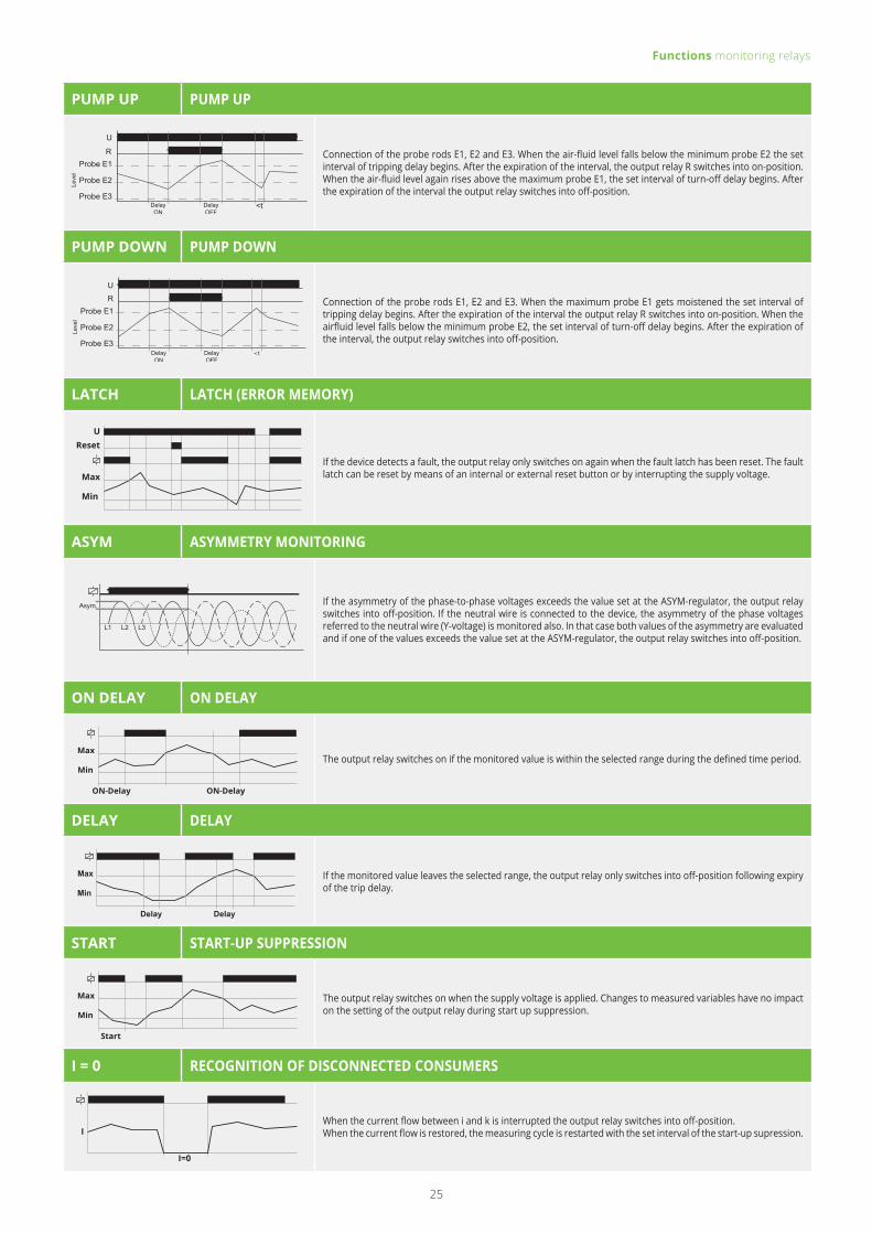
Grid and system protection An automatic disconnection device monitors the feed-in of energy to the 230/400V grid. In case of a power failure or disruptions by the energy supplier it is vital for small power plants to be disconnected within a few milliseconds to avoid any danger to people and equipment.
Complementary products:
Coupling units and signal converter
Switching relays + sockets
Current transformers
Softstarter, Thyristor control units and braking units
Hour meters and timers
Switching power supplies
Complementary products
Grid and system protection
10

Product seriesOur large and small quartet: ENYA, VEO, GAMMA and KAPPA – play it safe!
ENYA VEO GAMMA KAPPA
Product category Timing & monitoring relays, coupling units Timing & monitoring relays
Timing & monitoring relays, power monitors,
grid and system protectionTiming & monitoring relays
Dimensions (w x h x d) 17.5 / 35 x 87 x 65 mm 22.5 / 45 x 67 x 76 mm 22.5 / 45 × 90 × 108 mm 38 x 51 × 80 mm
Design Installation design Compact industrial design Industrial design Industrial Plug-In design, 11-poles
Labelling area - Freely positionable or fixed Fixed Fixed
Product standards EN 61812-1EN 60947
EN 61812-1EN 60947
EN 61812-1EN 50178EN 60947
EN 61812-1EN 50178
Energy consumption 0.8 – 1.3W extra low: 0.35 – 0.6W 1 – 1.5W 0.8 – 2W
Electrical connection Screw terminal Push-in terminal orscrew terminal Screw terminal Plug-in Housing mounted on
screw terminal socket
Overvoltage category / Rated impulse withstanding voltage
III / 4kV III / 4/6kV (protective separation) III / 4/6kV III / 4kV
Application field Building Industrial automation Industrial automation Building
Base accuracy ≤ 5% ≤ 2.5% ≤ 3% ≤ 5%
www.tele-online.comFOR THE ENTIRE PRODUCT RANGE PLEASE VISIT
ENYA VEO GAMMA KAPPA
11

ENYA VEO Installation design (45 mm
standard front dimension)
Timing and monitoring relays,
single and multifunction
Width 17.5 mm and 35 mm,
1 or 2 changeover contacts (CO)
UL listed, CE conformity marking
Temperature range -25 to +55°C
Recessed potentiometer buttons, analog indication by means of LED
12 to 240V AC/DC, powered by
measuring circuit
Industrial design for mounting plate and cable channels
Timing and monitoring relays,
single and multifunction
Width 22.5 mm and 45 mm,
1 or 2 changeover contacts (CO)
Low profile
UL listed, CE conformity marking
Temperature range -25 to +60°C
Recessed potentiometer buttons, analog indication by means of LED
12 to 240V AC/DC, powered by
measuring circuit
Product features
5 mm
60 mm
45 m
m
87 m
m
17.5 mm44 mm 76 mm 22.5 mm
67 m
m
Each of our products is characterized by special product features:
12

GAMMA KAPPA
www.tele-online.comMORE PRODUCT INFOS
22.5 mm
5 mm 103 mm
90 m
m
47 mm22 mm
45 m
m
80 mm
51 m
m
38 mm
Industrial design
Timing and monitoring relays,
single and multifunction
Width 22.5 mm and 45 mm,
1 or 2 changeover contacts (CO)
UL listed, CE conformity marking
Temperature range -25 to +55°C
Recessed potentiometer buttons, analog indication by means of LED, digital indication by means of LCD-Display
12 to 240V AC/DC, powermodules
12 to 500V AC; 24V DC
Industrial Plug-In housing (45 mm standard front dimension)
Timing and monitoring relays,
single and multifunction
Width 35 mm, 2 changeover
contacts (2CO) or 1 changeover and 1 normally open contact (1CO + 1NO)
CE conformity marking
Temperature range -25 to +55°C
Recessed potentiometer buttons, analog indication by means of LED
12 to 240V AC/DC, powered by
measuring circuit
13
Function overview timing relays
E ON delay
When the supply voltage U is applied, the set interval t begins. After the interval t has expired the output relay R switches into on-position. This status remains until the supply voltage is interrupted. If the supply voltage is interrupted before the expiry of the set interval, the interval t already expired is erased and is restarted when the supply voltage is next applied.
A OFF delay without auxiliary voltage
When the supply voltage U is supplied, the output relay R swiches into on-position. If the supply voltage is interrupted, the set interval t begins. After the set interval t has expired the output relay R switches into off-position. If the supply voltage is reconnected before the interval t has expired the interval already is erased and is restarted with the next cycle.
R OFF delay
The supply voltage U must be constantly applied to the device. When the control contact S is closed, the output relay R switches into on-position. If the control contact is opened, the set interval t begins. After the interval t has expired the output relay switches into off-position. If the control contact is closed again before the set interval has expired, the interval already expired is erased and is restarted.
S Star-Delta Start-up
When the supply voltage U is applied, the star-contact switches into on-position and the set star-time t1 begins. After the interval t1 has expired the star-contact switches into off-position and the set transit-time t2 begins. After the interval t2 has expired the delta-contact switches into on-position. To restart the function the supply voltage must be interrupted and re-applied.
ER ON delay and OFF delay with control contact
The supply voltage U must be constantly applied to the device. When the control contact S is closed, the set interval t1 begins. After the interval t1 has expired, the output relay R switches into on-position. If the control contact is opened, the set interval t2 begins. After the interval t2 has expired, the output relay Switches into off-position. If the control contact is opened before the interval t1 has expired, the interval already expired is erased and is restarted with the next cycle.
U
LED U/t
R <tt
U
LED U
R t <t t
U
U/t
S
R
LED
<tt
<t
UU/t
Y
LED
17-2817-18
t1 t2
RLED
U
U/t
S
R
LED
t2t1 <t1
Functions timing relays
Our timing relays have a variety of functions – here they are in detail:
14

Ec Additive ON Delay
When the supply voltage U is applied, the release for the interval starts. When the control contact S is closed, the set interval t begins. If the control contact S is opened during the set interval t, the interval stops, and the already expired interval is stored. During the lapse of time the control contact can be opened or closed as often as required. If the sum of the periods, in which the control contact S is closed reaches the set interval t the output relay R switches into on-position. The interval is stopped and a further activation of the control contact S remains without effect. By interrupting the supply voltage, the device will be reset. A possibly expired time t is deleted.
Es ON delay with control input
The supply voltage U must be constantly applied to the device. When the control contact S is closed, the set interval t begins. After the interval t has expired the output relay R switches into on-position. This status remains until the control contact is opened again. If the control contact is opened before the interval t has expired , the interval already expired is erased and is restarted with the next cycle.
ET ON delay two wire connected
When the supply voltage U is applied, the set interval t begins. After the interval has expired the thyristor switches on. This status remains until the supply voltage is interrupted. If the supply voltage is interrupted before the expiry of the interval, the interval already expired is erased and is restarted when the supply voltage is next applied.
Wu Single shot leading edge voltage controlled
When the supply voltage U is applied, the output relay R switches into on-position and the set interval t begins. After the interval t has expired the output relay switches into off-position. This status remains until the supply voltage is interrupted. If the supply voltage is interrupted before the interval t has expired, the output relay switches into off-position. The interval already is erased and is restarted when the supply voltage is next applied.
EWu ON delay single shot leading edge with control contact
When the supply voltage U is applied, the set interval t1 begins. After the interval t1 has expired, the output relay R switches into on-position and the set interval t2 begins. After the interval t2 has expired, the output relay switches into off-position. If the supply voltage is interrupted before the interval t1+t2 has expired, the interval already expired is erased and is restarted when the supply voltage is next applied.
nWu Maintained single shot leading edge
When the supply voltage U is applied, the output relay R switches into on-position and the set interval t begins. After the interval t has expired the output relay switches into off-position. This status remains until the supply voltage is interrupted. If the supply voltage is reconnected before the interval t has expired, the unit continues to perform the actual single shot.
Ws Single shot leading edge with control input
The supply voltage U must be constantly applied to the device. When the control contact S is closed, the output relay R switches into on-position and the set interval t begins. After the interval t has expired the output relay switches into off-position. During the interval, the control contact can be operated any number of times. A further cycle can only be started when the cycle run has been completed.
U
LED U/t
S
R tt
U
U/t
R
LED
t2t1
U
LED U/t
R <tt
U
T <tt
U
U/t
S
R
LED
t1 <t
U
LED U/t
S
R
t1 t2 t=t1+t2
U
LED U
R tt
Functions timing relays
15

EWs ON delay single shot leading edge with control contact
The supply voltage U must be constantly applied to the device. When the control contact S is closed, the set interval t1 begins. After the interval t1 has expired, the output relay R switches into on-position and the set interval t2 begins. After the interval t2 has expired, the output relay switches into offposition. During the interval, the control contact can be operated any number of times. A further cycle can only be started when the cycle run has been completed.
Wa Single shot trailing edge with control input
The supply voltage U must be constantly applied to the device. Closing the control contact S has no influence on the condition of the output R. When the control contact is opened, the output relay switches into on-position and the set interval t begins. After the set interval has expired, the ouput relay switches into off-position. During the interval, the control contact can be operated any number of times. A further cycle can only be started when the cycle run has been completed.
nWa Maintained single shot trailing edge
When the supply voltage U is supplied, the output relay R remains into off-position. As soon as the supply voltage is interrupted the output relay switches into on-position and the set interval t begins. After the set interval t has expired the output relay switches into off-position. When the supply voltage is reconnected before the interval t has expired, the unit continues to perform the actual single shot.
nWuWa Maintained single shot leading and trailing edge
When the supply voltage U is applied, the output relay R switches into on-position and the set interval t begins. After the interval t has expired the output relay switches into off-position. As soon as the supply voltage is interrupted the output relay switches into on-position again and the set interval t begins. After the set interval t has expired the output relay switches into off-position. If the supply voltage is interrupted (nWu) or reconnected (nWa) before the interval t has expired the unit continues to perform the actual single shot
WsWa Single shot leading and single shot trailing edge with control contact
The supply voltage U must be constantly applied to the device. When the control contact S is closed, the output relay R switches into on-position and the set interval t1 begins. After the interval t1 has expired, the output relay R switches into off-position. If the control contact is opened, the output relay again switches into on-position and the set interval t2 begins. After the interval t2 has expired the output relay switches into off-position. During the interval, the control contact can be operated any number of times.
Bi Flasher pulse first
When the supply voltage U is applied, the output relay R switches into on-position and the set interval t begins. After the interval t has expired, the output relay R switches into off-position and the set interval t begins again. The output relay is triggered at a ratio of 1:1 until the supply voltage is interrupted.
Bp Flasher pause first
When the supply voltage U is applied, the set interval t begins. After the interval t has expired, the output relay R switches into on-position and the set interval t begins again. After the interval t has expired, the output relay switches into off-position. The output relay is triggered at a ratio of 1:1 until the supply voltage is interrupted.
U
LED U/t
R t ttt
U
LED U/t
R t t tt
U
LED U/t
S
R t1 t2 t1 t2
U
R
LED U
t t t t t
U
LED U
R t t
U
LED U/t
S
R tt
Functions timing relays
U
U/t
S
R
LED
t2t1
16

Wt Pulse sequence monitoring
When the supply voltage U is applied, the set interval t1 begins and the output relay R switches into on-position. After the interval t1 has expired, the set interval t2 begins. So that the output relay R remains in on-position, the control contact S must be closed and opened again within the set interval t2. If this does not happen, the output relay R switches into off-position and all further pulses at the control contact are ignored. To restart the function the supply voltage must be interrupted and reapplied.
Ii Asymmetric flasher pulse first
When the supply voltage U is applied, the output relay R switches into on-position and the set interval t1 begins. After the interval t1 has expired, the output relay switches into off-position and the set interval t2 begins. After the interval t2 has expired, the output relay switches into on-position. The output relay is triggered at the ratio of t1:t2 until the supply voltage is interrupted.
Ip Asymmetric flasher pause first
When the supply voltage U is applied, the set interval t1 begins. After the interval t1 has expired, the output relay R switches into on-position and the set interval t2 begins. After the interval t2 has expired, the output relay switches into off-position. The output relay is triggered at the ratio of t1:t2 until the supply voltage is interrupted.
T, TW Function automatic timer with (TW) or without (T) switch-off warning
After the pushbutton (control input) has been pressed, the output relay R closes and the set interval t begins. If the pushbutton is pressed again before the interval has expired, the interval begins again (restart function complies with EN 60669-2-3). Rapid, multiple pressing of the pushbutton (pumping) adds 2, 3 or more time intervals to extend the time up to 60 min. Prolonged pressure on the button (>2 s) aborts the interval running and switches the relay off (energy saving function). In the TW mode the device provides a switch-off warning (in accordance with DIN 180-158-2) by generating short pulses (flashing) at 30s, 15s and 5s prior to switch-off.
P, PN Impulse switch mode
In this mode, every keypress of the pushbutton (control input) toggles the output relay R (flip-flop). In function P, the output relay remains in off-position, whenever the supply voltage is applied. In function PN, the output relay switches into on-position after applying the supply voltage U, if the output relay was in on-position last before power failure. In both functions the output relay switches into on-position, if a short voltage impulse (<2s) is applied to the additional control input (central ON). A longer voltage impulse (>2s) opens the output relay (central OFF).
P ( R ) Impulse switch mode with off delay
In this mode, every keypress toggles the output relay R (flip-flop). After the pushbutton (control input) has been pressed, the output relay closes and the set interval t begins. After the interval has expired the output relay switches into off-position. If the pushbutton is pressed again before the interval has expired, the interval will be canceled and the output relay switches into off-position.
U
LED U/t
S
R ∞t t<t <t
U
U/t
R
LED
t1 t2 t1 t2 t1
U
LED U/t
R t1 t2 t1 t2 t1
U
B1
R <ttt t 2t
> 2s < 2s
TW 15s 10s5s
U
B1
R
U
B1
R t<tt
Functions timing relays
17

ENYA series timing relays
TYPE DESIGNATION E1ZM10 E1ZM20 E1ZMQ10 E1ZMW10 E3ZM20
ORDER INFORMATION
Art. No. single package 110100 (12-240V)110200 (24-240V) 110210 110202 - 111100
Art. No. package 10 pcs. 110100A (12-240V)110200A (24-240V) - 110202A 110206A -
FUNCTIONALITY MULTIFUNCTION MULTIFUNCTION MULTIFUNCTION MULTIFUNCTION MULTIFUNCTION
E On delay
R Off delay
Es On delay with control contact
Wu Single shot leading edge, voltage-controlledWs Single shot leading edge with control contactWa Single shot trailing edge with control contact
Bp Flasher pause first
Wt Pulse repetition analysis
WsWa Single shot leading and trailing edge with control contact
POWER SUPPLY CIRCUIT
Supply voltage 12 – 240V AC/DC24 – 240V AC/DC 24 – 240V AC/DC 24 – 240V AC/DC 24 – 240V AC/DC 12 – 240V AC/DC
Setting range 48 – 63 Hz
TIME CIRCUITS
Time ranges 7
Setting range 0.05 s – 100 h
INPUT CIRCUIT
Control signal
OUTPUT CIRCUIT
Number of switch contacts 1 CO contact 1 CO, 1 NO contact 1 CO contact 1 CO contact 1 CO contact
Max. switching capacity 2000VA (8A / 250V AC)
DESIGN
Dimensions (w x h x d) 17.5 x 87 x 65 mm 35 x 87 x 65 mm
Certificates CE, cULus, EAC CE, EAC CE, cULus, EAC CE, cULus, EAC CE, cULus, EAC
18

ENYA series timing relays
TYPE DESIGNATION E1ZNT E1Z1E10 E1ZI10 E3ZI20 E3ZS20
ORDER INFORMATION
Art. No. single package 110500 - 110101 111101 111300
Art. No. package 10 pcs. - 110204A - - -FUNCTIONALITY EMERGENCY
LIGHT TESTER ON DELAY ASYMMETRIC FLASHER ASYMMETRIC FLASHER STAR DELTA
E On delay
ER On delay and off delay with control contactEWu On delay single shot lead-ing edge, voltage-controlledWs Single shot leading edge with testkeyEWs On delay single shot lead-ing edge with control contact
lp Asymmetric flasher pause first
li Asymmetric flasher pulse first
Wt Pulse repetition analysis
WsWa Single shot leading and trailing edge with control contact
S Star-Delta start-up
POWER SUPPLY CIRCUIT
Supply voltage 230V AC 24 to 240V AC/DC 12 to 240V AC/DC 12 – 240V AC/DC 12 – 240V AC/DC
Frequency range 48 – 63 Hz
TIME CIRCUITS
Time ranges 1 7 7 7 4
Setting range 10 min – 3 h 0.05 s – 100 h 1 s – 100 h 1 s – 100 h 0.5 s – 3 min
INPUT CIRCUIT
Control signal Integrated test key
OUTPUT CIRCUIT
Number of switch contacts 1 CO contact 1 CO contact 1 CO contact 2 CO contacts 2 CO contacts
Max. switching capacity NC: 4000VA (10A / 250V AC)NO: 1250VA (5A / 250V AC) 2000VA (8A / 250V AC) 2000VA (8A / 250V AC) 2000VA (8A / 250V AC) 2000VA (8A / 250V AC)
DESIGN
Dimensions (w x h x d) 17.5 x 87 x 65 mm 35 x 87 x 65 mm
Certificates CE, EAC CE, cULus, EAC CE, cULus, EAC CE, cULus, EAC CE, cULus, EAC
www.tele-online.comTHIS IS A SMALL OVERVIEW OF OUR PRODUCTS FOR THE ENTIRE PRODUCT RANGE PLEASE VISIT
19

VEO series timing relays
TYPE DESIGNATION V2ZM10 V2ZM10-A V2ZQ10 V2ZI10 V2ZE10
ORDER INFORMATION
Art. No. Screw terminal 125100 - 125150 125200 125110
Art. No. Push-in terminal 125600 - 125650 125210 125610
Art. No. Packaging unit 10 pcs. 125100A 125101A 125150A - 125110A
FUNCTIONALITY MULTIFUNCTION MULTIFUNCTION MULTIFUNCTION 2-TIME MULTIFUNCTION ON DELAY
E On delay
R Off delayEs On delay with control contactWu Single shot leading edge, voltage-controlledEWu ON delay single shot lead-ing edge, voltage-controlledWs Single shot leading edge with control contactWa Single shot trailing edge with control contact
Bi Flasher pulse first
Bp Flasher pause first
Wt Pulse repetition analysis
Ec Additive ON Delay
li Asymmetric flasher pulse first
lp Asymmetric flasher pause first
SUPPLY CIRCUIT
Supply voltage 12 to 240V AC/DC 12 to 240V AC/DC 24 to 240V AC/DC 12 to 240V AC/DC 12 to 240V AC/DC
Frequency range 48 – 63 Hz
TIME CIRCUITS
Time ranges 10
Setting range 0.05 s – 100 h
INPUT CIRCUIT
Control signal
OUTPUT CIRCUIT
Anzahl der Schaltkontakte 1 CO contact
Max. Schaltleistung 2000VA (8A / 250V AC)
DESIGN
Dimensions (w x h x d) 22.5 x 67 x 76 mm
Certificates CE, cULus, EAC (Devices with Push-in terminal are not cULus listed)
20

TYPE DESIGNATION V2ZR10 V2ZA10 V2ZS20 V2ZET
ORDER INFORMATION
Art. No. Screw terminal 125120 125500 125300125130 (12-240V AC/DC)125132 (50ms 230V AC)125133 (50ms 110V AC)
Art. No. Push-in terminal 125620 125510 125310 -
Art. No. Packaging unit 10 pcs. 125120A - - -
FUNCTIONALITY OFF DELAY MULTIFUNKTION STAR DELTA 2-WIRE ON DELAY
E On delay
ET On delay, two wire connected
R Off delay
A Off delay without auxiliary voltage
nWu Maintained single shot leading edgenWa Maintained single shot trailing edgenWuWa Maintained single shot leading and trailing edge
S Star-delta start-up
POWER SUPPLY CIRCUIT
Supply voltage 12 to 240V AC/DC 12 to 240V AC/DC 12 to 240V AC/DC12 to 240V AC/DC (125130)
230V AC (125132)110V AC (125133)
Frequency range 48 – 63 Hz
TIME CIRCUITS
Time ranges 10 4 4 5 (125130)1 (125132, 125133)
Setting range 0.05 s – 100 h 0.1 s – 3 min 0.05 s – 3 min 0,05 s – 1 h (125130)50 ms (125132, 125133)
INPUT CIRCUIT
Control signal
OUTPUT CIRCUIT
Number of switch contacts 1 CO contact 1 CO contact 2 NO contacts 1 Thyristor output
Max. switching capacity 2000VA (8A / 250V AC) 1250VA (5A / 250V AC) 750VA (3A / 250V AC) 125VA / 250V AC
DESIGN
Dimensions (w x h x d) 22.5 x 67 x 76 mm
Certificates CE, cULus, EAC (Devices with Push-in terminal are not cULus listed) CE, EAC
www.tele-online.com
VEO series timing relays
THIS IS A SMALL OVERVIEW OF OUR PRODUCTS FOR THE ENTIRE PRODUCT RANGE PLEASE VISIT
21

TYPE DESIGNATION G2ZM20 G2ZMF11 G2ZI20 G2ZIF20 G2ZS20
ORDER INFORMATION
Art. No. (with power module) - 120100 - 120200 120300
Art. No. (Zoom voltage) 120401 120103 120501 120201 120301
FUNCTIONALITY MULTIFUNCTION MULTIFUNCTION 2-TIME MULTIFUNCTION 2-TIME MULTIFUNCTION STAR-DELTA
E On delay
R Off delay
ER On delay and off delay with control contact
Es On delay with control contact
Wu Single shot leading edge, voltage-controlledWs Single shot leading edge with control contactWa Single shot trailing edge with control contactEWu ON delay single shot lead-ing edge, voltage-controlledEWs ON delay single shot lead-ing edge with control contactWsWa Single shot leading and trailing edge with control contact
Bi Flasher pulse first
Bp Flasher pause first
li Asymmetric flasher pulse first
lp Asymmetric flasher pause first
S Star-delta start-up
SUPPLY CIRCUIT
Supply voltage 12 to 240V AC/DC24 to 240V AC/DC
or selectable via power modules TR2, SNT2
12 to 240V AC/DC24 to 240V AC/DC
or selectable via power modules TR2, SNT2
24 to 240V AC/DC or selectable via power
modules TR2, SNT2 Frequency range 48 – 63 Hz
TIME CIRCUITS
Time ranges 7 16 7 10 4
Setting range 0.05 s – 100 h 0.05 s – 30 d 0.05 s – 100 h 0.05 s – 10 h 0.05 s – 3 min
INPUT CIRCUIT
Control signal
Remote potentiometer
OUTPUT CIRCUIT
Number of switch contacts 2 CO contacts 1 delayed / 1 instantaneous CO contact 2 CO contacts 2 CO contacts 2 CO contacts
Max. switching capacity 1250VA (5A / 250V AC)
DESIGN
Dimensions (w x h x d) 22.5 x 90 x 108 mm
Certificates CE, cULus, EAC
GAMMA series timing relays
Please refer to the chapter accessories for detailed information and ordering data of remote potentiometers and to the chapter accessories for detailed information and ordering data of power modules TR2, TR3 and SNT2
22

TYPE DESIGNATION K3ZM20K3ZM20P K3ZA20 3MIN K3ZI20 K3ZS20 R11X PF-113BE/M (ES12)
ORDER INFORMATION ACCESSORIES FOR KAPPA RELAYS
Art. No. 135100 135200 135400 135101 135300 180055 180136
FUNCTIONALITY MULTIFUNCTION MULTIFUNCTION 2-TIME MULTIFUNCTION STAR-DELTA SOCKETS
E On delay 11-pols socket for mounting KAPPA re-lays on DIN-Rail TS 35R Off delay
ER On delay and off delay with control contact
Es On delay with control contact
Wu Single shot leading edge, voltage-controlledWs Single shot leading edge with control contactWa Single shot trailing edge with control contactnWu Maintained single shot leading edgenWa Maintained single shot trailing edgeEWu ON delay single shot leading edge, voltage-controlledEWs ON delay single shot leading edge with control contactWsWa Single shot leading and trailing edge with control contactnWuWa Maintained single shot leading and trailing edge
Bp Flasher pause first
li Asymmetric flasher pulse first
lp Asymmetric flasher pause first
Wt Pulse sequence monitoring
A Off delay without auxiliary voltage
S Star-delta start-up
SUPPLY CIRCUIT
Supply voltage 12 to 240V AC/DC 24 to 240V AC/DC 12 to 240V AC/DC 12 to 240V AC/DC Depends on selcted KAPPA relays
Frequency range 48 – 63 Hz Depends on selcted KAPPA relays
TIME CIRCUITS
Time ranges 7 4 7 4
Setting range 0.05 s – 100 h 0.1 s – 3 min 0.05 s – 100 h 0.05 s – 3 min
INPUT CIRCUIT
Control signal (K3ZM20P potential free)
OUTPUT CIRCUIT
Number of switch contacts 2 CO contacts
Max. switching capacity 2000VA (8A / 250V AC)
DESIGN
Dimensions (w x h x d) 38 x 51 x 80 mm 38 x 61,5 x 26 mm 38 x 75 x 26 mm
Certificates CE, EAC CE, cRUus CE, cRUus, CSA
KAPPA series timing relays / Sockets R11X and PF-113BE/M
23

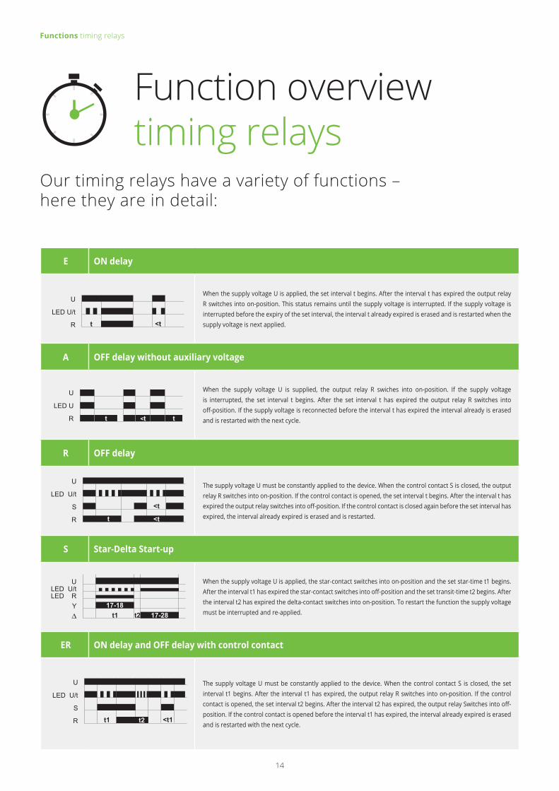
Function overview monitoring relays
Functions monitoring relays
O OVER
Max
Min
If the measured value exceeds the adjusted MAX threshold, the output relay switches into off-position.The output relay switches into on-position again, as soon as the measured value falls below the adjusted MIN threshold.
U UNDER
If the measured value falls below the adjusted MIN threshold, the output relay switches into off-position.The output relay switches into on-position again, as soon as the measured value exceeds the adjusted MAX threshold.
W WINDOW
Max
Min
If the measured value falls below the adjusted MIN threshold, the output relay switches into off-position. The output relay switches into on-position again, as soon as the measured value exceeds the adjusted MIN threshold.If the measured value exceeds the adjusted MAX threshold, the output relay switches into off-position. The output relay switches into on-position again, as soon as the measured value falls below the adjusted MAX threshold.
2MIN MINIMUM MONITORING
If the measured value falls below the adjusted MAX threshold, the output relay Rel1 switches into off-position. If the measured value falls below the adjusted MIN threshold, the output relay Rel2 switches into off-position.The output relays Rel1 and Rel2 switch into on-position again, as soon as the measured value exceeds the according adjusted threshold (MAX or MIN).
2MAX MAXIMUM MONITORING
If the measured value exceeds the adjusted MIN threshold, the output relay Rel2 switches into off-position. If the measured value exceeds the adjusted MAX threshold, the output relay Rel1 switches into off-position. The output relays Rel1 and Rel2 switch into on-position again, as soon as the measured value falls below the according adjusted threshold (MAX or MIN).
MM MINIMUM AND MAXIMUM MONITORING (MIN/MAX)
If the measured value falls below the adjusted MIN threshold, the output relay Rel2 switches into off-position. The output relay Rel2 switches into on-position again, as soon as the measured value exceeds the adjusted MIN threshold. If the measured value exceeds the adjusted MAX threshold, the output relay Rel1 switches into off-position. The output relay Rel1 switches into on-position again, as soon as the measured value exceeds the adjusted MIN threshold.
TEMP TEMPERATURE MONITORING
If the supply voltage U is applied and the cumulative resistance of the PTC-circuit is less than 3.6kΩ (standard temperature of the motor), the output relay R switches into on-position. When the cumulative resistance of the PTC-circuit exceeds 3.6kΩ, the output relay switches into off-position. The output relay switches into on-position again after the cumulative resistance falls below 1.6kΩ.
U
Max
Rel 1Rel 2
Min
U
Max
Rel 1Rel 2
Min
U
Max
Rel 1Rel 2
Min
Rel
PTC
3,6kΩ
1,8kΩ
Max
Min
24
PUMP UP PUMP UP
U
Probe E1
Probe E2
Probe E3
Leve
l
<t
R Connection of the probe rods E1, E2 and E3. When the air-fluid level falls below the minimum probe E2 the set interval of tripping delay begins. After the expiration of the interval, the output relay R switches into on-position. When the air-fluid level again rises above the maximum probe E1, the set interval of turn-off delay begins. After the expiration of the interval the output relay switches into off-position.
PUMP DOWN PUMP DOWN
U
Probe E1
Probe E2
Probe E3
Leve
l
R Connection of the probe rods E1, E2 and E3. When the maximum probe E1 gets moistened the set interval of tripping delay begins. After the expiration of the interval the output relay R switches into on-position. When the airfluid level falls below the minimum probe E2, the set interval of turn-off delay begins. After the expiration of the interval, the output relay switches into off-position.
LATCH LATCH (ERROR MEMORY)
Max
Min
ResetU
If the device detects a fault, the output relay only switches on again when the fault latch has been reset. The fault latch can be reset by means of an internal or external reset button or by interrupting the supply voltage.
ASYM ASYMMETRY MONITORING
Asym.
L1 L2 L3
If the asymmetry of the phase-to-phase voltages exceeds the value set at the ASYM-regulator, the output relay switches into off-position. If the neutral wire is connected to the device, the asymmetry of the phase voltages referred to the neutral wire (Y-voltage) is monitored also. In that case both values of the asymmetry are evaluated and if one of the values exceeds the value set at the ASYM-regulator, the output relay switches into off-position.
ON DELAY ON DELAY
The output relay switches on if the monitored value is within the selected range during the defined time period.
DELAY DELAY
If the monitored value leaves the selected range, the output relay only switches into off-position following expiry of the trip delay.
START START-UP SUPPRESSION
The output relay switches on when the supply voltage is applied. Changes to measured variables have no impact on the setting of the output relay during start up suppression.
I = 0 RECOGNITION OF DISCONNECTED CONSUMERS
When the current flow between i and k is interrupted the output relay switches into off-position.When the current flow is restored, the measuring cycle is restarted with the set interval of the start-up supression.
Functions monitoring relays
Max
Min
Delay Delay
Max
Min
ON-DelayON-Delay
Max
Min
Start
I
I=0
25

KAPPA series monitoring relays
TYPE DESIGNATION K3PF400VSY02 K3YM400VSY20 K3IM5AACL20 K3UM230VAC02 K3UM24VDC02
ORDER INFORMATION
Art. No. 1380301 1380402 1380202 1380106 1380107
FUNCTIONALITY 3-phase AC voltage monitoring
3- and 1-phase AC voltage monitoring
1-phase AC current monitoring
1-phase AC voltage monitoring
1-phase AC voltage monitoring
O ... Over
U ... Under
W ... Window
SEQ ... Phase sequence
Phase failure
ASYM ... Asymmetry
+LATCH ... Error memory
SWITCHING THRESHOLD
Maximum - 80 to 130% of UN 10 to 100% of UN 80 to 120% of UN 80 to 130% of UN
Minimum - 70 to 120% of UN 5 to 95% of UN 70 to 110% of UN 75 to 125% of UN
Asymmetry 5 to 30%, OFF 5 to 30%, OFF - - -
MEASURING CIRCUIT
Measuring variable 3(N)~AC Sinus
3(N)~ AC Sinus
CurrentAC Sinus
Voltage ACAC Sinus
Voltage ACAC Sinus
Measuring input UN= 400/230V AC UN= 400/230V AC 5A AC UN= 230V AC UN= 24V DC
SUPPLY CIRCUIT
Supply voltage= Measuring voltage3(N)~ 400/230V AC
-30% to +30%
= Measuring voltage3(N)~ 400/230V AC
-30% to +30%
230V AC-15% to +10%
= Measuring voltage3(N)~ 400/230V AC
-30% to +20%
= Measuring voltage24V DC
-25% to +30%
Frequency range 48 – 63 Hz 48 – 63 Hz 48 – 63 Hz 48 – 63 Hz -
TIME CIRCUITS
Start-up surpression time (START) - - 0 – 10 s - -
Tripping delay (DELAY) fixed, approx. 100 ms 0.1 – 10 s 0.1 – 10 s - -
OUTPUT CIRCUIT
Number of switch contacts 2 CO contacts
Max. switching capacity 1250VA (5A / 250V AC)
DESIGN
Dimensions (w x h x d) 38 x 51 x 80 mm
Certificates CE, EAC
26

TYPE DESIGNATION E1IM10AACL10 230VAC E3IM10AL20 230V AC E3IF500MAAC20 E3YF400VE20 0.85 E3YF400VT02 0.85
ORDER INFORMATION
Art. No. single package 1340200 1341200 1341201 1341404 1341402
FUNCTIONALITY 1-phase AC current monitoring
1-phase AC/DC current monitoring
1-phase AC current monitoring
3-phase AC voltage monitoring
3-phase AC voltage monitoring
O ... Over
U ... Under
W ... Window
Test function
SWITCHING THRESHOLD
Maximum 10 to 100% of IN 10 to 100% of IN - - -
Minimum 5 to 95% of IN 5 to 95% of IN 50mA to 500mA fixed, 195.5V (0.85) fixed, 195.5V (0.85)
Asymmetry - - - - -
MEASURING CIRCUIT
Measuring variable CurrentAC Sinus
Current AC/DCAC Sinus
CurrentAC Sinus
3(N)~ AC Sinus
3(N)~ AC Sinus
Measuring input 10A AC 100mA / 1A / 10A AC/DC 500mA UN= 400/230V AC UN= 400/230V AC
SUPPLY CIRCUIT
Supply voltage 230V AC-15% to +15% 230V AC 230V AC
= Measuring voltage 3(N)~ 400/230V AC
-30% to +30%
= Measuring voltage 3(N)~ 400/230V AC
-30% to +30%
Frequency range 48 – 63 Hz 48 – 63 Hz 48 – 63 Hz 48 – 63 Hz 48 – 63 Hz
TIME CIRCUITS
Start-up surpression time (START) - 0 - 10 s 0 - 20 min - -
Tripping delay (DELAY) 0,1 – 10 s 0,1 – 10 s 0 – 20 min - fixed, approx. 200 ms
ON DELAY - - - fixed, 1 min -
OUTPUT CIRCUIT
Number of switch contacts 1 CO contact 2 CO contact 2 CO contact 2 CO contact 2 CO contact
Max. switching capacity 1250VA (5A / 250V AC) 1250VA (5A / 250V AC) 1250VA (5A / 250V AC) 1250VA (5A / 250V AC) 1250VA (5A / 250V AC)
DESIGN
Dimensions (w x h x d) 17,5 x 87 x 65 mm 35 x 87 x 65 mm
Certificates CE, cULus, EAC CE, EAC CE, EAC CE, cULus, EAC
ENYA series monitoring relays
27

ENYA series monitoring relays
TYPE DESIGNATION E1PF400VSY01 E1PF400VS01 E1PF480Y/277VSY01 E1YF400V01 E3YF400V02
ORDER INFORMATION
Art. No. single package 1340300 - 1340306 1340402 (0.85)1340410 (0.70) 1341401
Art. No. package 10 pcs. 1340300A 1340301A - 1340402A (0.85) -
FUNCTIONALITY 3-phase AC voltage monitoring
U ... Under
W ... Window
SEQ ... Phase sequence
Phase failure
ASYM ... Asymmetry
SWITCHING THRESHOLD
Minimum - - - fixed, 195.5V (0.85)fixed, 161V (0.70) fixed, 195.5V
Asymmetry 5 to 25%, OFF 5 to 25%, OFF 5 to 25%, OFF - -
MEASURING CIRCUIT
Measuring variable 3(N)~ AC Sinus
3(N)~ AC Sinus
3~ AC Sinus
3(N)~ AC Sinus
3(N)~ AC Sinus
Measuring input UN= 400/230V AC UN= 400/230V AC UN= 208/120V to 480/277V AC UN= 400/230V AC UN= 400/230V AC
SUPPLY CIRCUIT
Supply voltage= Measuring voltage3(N)~ 400/230V AC
-30% to +30%
= Measuring voltage3(N)~ 400/230V AC
-30% to +30%
= Measuring voltage3~ 208/120V to
480/277V AC-10% to +10%
= Measuring voltage3(N)~ 400/230V AC
-30% to +30%
= Measuring voltage3(N)~ 400/230V AC
-30% to +30%
Frequency range 48 – 63 Hz
TIME CIRCUITS
Tripping delay (DELAY) fixed, approx. 100ms fixed, approx. 100ms fixed, approx. 100ms fixed, approx. 200ms fixed, approx. 200ms
OUTPUT CIRCUIT
Number of switch contacts 1 CO contact 1 CO contact 1 CO contact 1 CO contact 2 CO contacts
Max. switching capacity 1250VA (5A / 250V AC)
DESIGN
Dimensions (w x h x d) 17.5 x 87 x 65 mm 17.5 x 87 x 65 mm 17.5 x 87 x 65 mm 17.5 x 87 x 65 mm 35 x 87 x 65 mm
Certificates CE, EAC CE, EAC CE, cULus, EAC CE, EAC CE, cULus, EAC
28

ENYA series monitoring relays
TYPE DESIGNATION E1YM400VS10 E1YM480/277VS10 E3YM230VS20 E1UM230V01 E3LM10 230VAC
ORDER INFORMATION
Art. No. single package 1340405 1340409 1341406 1340101 1341500
FUNCTIONALITY 3- and 1-phase AC voltage monitoring
3-phase AC voltage monitoring
3- and 1-phase AC voltage monitoring
1-phase AC/DC voltage monitoring
Level monitoring of con-ductive liquids
O ... Over
U ... Under
W ... Window
SEQ ... Phase sequence
Phase failure
Pump up
Pump down
SWITCHING THRESHOLD
Maximum 80 to 130% of UN 75 to 110% of UN 80 to 130% of UN 80 to 120% of UN -
Minimum 70 to 120% of UN 65 to 100% of UN 70 to 120% of UN 75 to 115% of UN -
Asymmetry 5 to 25%, OFF - - - -
MEASURING CIRCUIT
Measuring variable 3(N)~ AC Sinus
3~ AC Sinus
3(N)~ AC Sinus
Voltage AC/DCAC Sinus
Liquid level via conductive probes
Measuring input UN= 400/230V AC UN= 480/277V AC UN=230/132V AC 24V AC/DC; 230V AC 0.25 to 100kΩ
SUPPLY CIRCUIT
Supply voltage= Measuring voltage3(N)~ 400/230V AC
-30% to +30%
= Measuring voltage3~ 480/277V AC-35% to +10%
= Measuring voltage3(N)~ 400/230V AC
-30% to +30%
= Measuring voltage24V AC/DC; 230V AC
-25% to +20%
230V AC-15% to +10%
Frequency range 48 – 63 Hz 48 – 63 Hz 48 – 63 Hz 48 – 63 Hz or DC 48 – 63 Hz
TIME CIRCUITS
Tripping delay (DELAY) 0.1 – 10 s 0.1 – 10 s 0 – 30 s - 0.5 – 10 s
OFF DELAY - - - - 0.5 – 10 s
OUTPUT CIRCUIT
Number of switch contacts 1 CO contact 1 CO contact 2 CO contacts 1 CO contact 1 CO contact
Max. switching capacity 1250VA (5A / 250V AC)
DESIGN
Dimensions (w x h x d) 17.5 x 87 x 65 mm 17.5 x 87 x 65 mm 35 x 87 x 65 mm 17.5 x 87 x 65 mm 35 x 87 x 65 mm
Certificates CE, EAC CE, cULus, EAC CE, EAC CE, cULus, EAC CE, cULus, EAC
29

VEO series monitoring relays
TYPE DESIGNATION V2PF480Y/277VSY01 V2PM400Y/230VS10 V2UM230V10 V2UF230V10 V4PF480Y/277VSYTK02
ORDER INFORMATION
Art. No. screw terminal 2100000 2100500 2100300 2100600 2104200
Art. No. push-in terminal 2100010 2100510 2100310 - 2104210
Art. No. package 10 pcs. 2100000A - - - -
FUNCTIONALITY 3- phase ACvoltage monitoring
3- phase ACvoltage monitoring
1- phase AC/DCvoltage monitoring
1- phase undervoltage voltage drop detector
3- phase ACvoltage monitoring
O ... Over
U ... Under
W ... Window
SEQ ... Phase sequence
Phase failure
ASYM ... Asymmetrie
Voltage interruptions (fast detection) Temperature monitoring (PTC)
SWITCHING THRESHOLD
Maximum - 75 to 130% of UN 80 to 115% of UN - -
Minimum - 70 to 125% of UN 75 to 110% of UN 165V AC -
Asymmetry 5 to 25%, OFF - - - 5 to 25%, OFF
MEASURING CIRCUIT
Measuring variable 3~ AC Sinus
3~ AC Sinus
Voltage AC/DCAC Sinus Voltage AC Temperature,
Voltage 3~ AC Sinus
Measuring input UN= 208/120V to 480/277V AC UN= 400/230V AC 24V AC/DC; 230V AC UN= 180 to 230V AC UN= 208/120V
to 480/277V AC
SUPPLY CIRCUIT
Supply voltage
= Measuring voltage3~ 208/120V
to 480/277V AC-10% to +10%
= Measuring voltage3(N)~ 400/230V AC
-35% to +35%
= Measuring voltage24V AC/DC; 230V AC24V: -30% to +30%
230V: -30% to +20%
= Measuring voltage230V AC
= Measuring voltage3~ 208/120V
to 480/277V AC-10% to +10%
Frequency range 48 – 63 Hz 16.6 – 400 Hz 16.6 – 400 Hz or DC 48 – 63 Hz 48 – 63 Hz
TIME CIRCUITS
ON DELAY approx. 400 ms approx. 200 ms approx. 300 ms 0.5 – 10 s approx. 500 ms
Tripping delay (DELAY) < 250 ms 0.1 – 10 s 0.1 – 10 s - approx. 250 ms
Response time short voltage interruptions - - - 10 – 40 ms -
OUTPUT CIRCUIT
Number of switch contacts 1 CO contact 1 CO contact 1 CO contact 1 CO contact 2 CO contacts
Max. switching capacity 2000VA (8A / 250V AC)
DESIGN
Dimensions (w x h x d) 22.5 x 67 x 76 mm 22.5 x 67 x 76 mm 22.5 x 67 x 76 mm 22.5 x 67 x 76 mm 45 x 67 x 76 mm
Certificates CE, cULus, EAC CE, cULus, EAC CE, cULus, EAC CE, EAC CE, cULus, EAC
Devices with Push-in terminal are not cULus listed
30

VEO series monitoring relays
TYPE DESIGNATION V2TF01 V2IM10AL10 V4IM100AL20V4IM35AL20 V4IA100A V4LM4S30
ORDER INFORMATION
Art. No. screw terminal 2100100 2100400 2104401(100A)2104402 (35A) 2104420 2104500
Art. No. push-in terminal 2100110 2100410 2104410 (100A) - -
FUNCTIONALITY
O ... Over
10 functions selectable via rotary switch - function
overview refer to page 7
U ... UnderW ... Window2MAX … Maximum monitoringMM … Min. and max. monitoring+LATCH ... Error memoryTemperature monitoring (PTC)Short circuit monitoring (PTC)
SWITCHING THRESHOLD
Maximum ≥ 3.6kΩ (switch-off resistance) 10 to 100% of IN 10 to 100% of IN - Sensitivity: 10kΩ - 500kΩ
Vsense: 20, 40, 60, 80, 100%
Minimum ≤ 1.6kΩ (switch-on resistance) 5 to 95% of IN 5 to 95% of IN - Sensitivity: 250Ω – 12.5kΩ
Vsense: 20, 40, 60, 80, 100%
Zero...Zero point - - - 0%, 25%, 50% and 75% of nominal value -
Zero Fine…Fine setting zero point - - - 0 - 25% of nominal value -
Span…Measuring span - - - 25%, 50%, 75% and 100% of nominal value -
MEASURING CIRCUIT
Measuring variable Temperature Current AC/DCAC Sinus
Current AC/DCAC Sinus
Current AC/DCAC Sinus
Liquid level with conductive probes (type SK1, SK5)
Measuring input - 10A AC/DC
V4IM100AL20:100A AC/DC Built-incurrent transformer
V4IM35AL20:35A AC/DC Built-in
current transformer
100A AC/DC Built-in current transformer
Low (L): 250Ω – 12.5kΩHigh (H): 10kΩ - 500kΩ
SUPPLY CIRCUIT
Supply voltage 24 – 240V AC/DC-15% to +10%
AC: 110 - 240VDC: 24 - 240V
AC: -15% to +15%DC: -30% to +30%
24 - 240V AC/DCAC: -15% to +10%DC: -30% to +30%
AC: 48-240VDC: 24-240V
AC: -10% to +10%DC: -15% to +20%
24-240V AC/DC AC: -10% to +10%DC: -25% to +25%
Frequency range 16.6 to 400Hz or DC 16.6 to 400Hz or DC 16.6 to 400Hz or DC 16.6 to 400Hz or DC 16.6 to 400Hz or DC
TIME CIRCUITS
ON DELAY approx. 50 ms approx. 300 ms approx. 300 ms - -Start-up surpression time (START) - - 0 – 10 s - -Tripping delay (DELAY) - 0.1 – 10 s 0.1 – 10 s - -Delay (Measuring Filter) - - - - 1-10s
OUTPUT CIRCUIT
Analog output - - -
0 ... 20 mA / 4 ... 20 mA10 mA ±10 mA / 12 mA
±8 mA(Burden: max. 300Ω)
0 ... 10 V5 V ±5 V
(Burden: max. 1,5kΩ)
-
Number of switch contacts 1 NO contact 1 CO contact - - 3 NO contactsMax. switching capacity 2000VA (8A/ 250V AC) - 1250VA (5A / 250V AC)
DESIGN
Dimensions (w x h x d) 22.5 x 67 x 76 mm 22.5 x 67 x 76 mm 45 x 67 x 76 mm 45 x 67 x 76 mm 45 x 67 x 76 mm
Certificates CE, cULus, EAC CE, EAC CE, cULus, EAC
Devices with Push-in terminal are not cULus listed
31

TYPE DESIGNATION G2PF400VS02 G2PM400VSY10G2PM400VSY20
G2TF01G2TF02 G2TFKN02 G2LM20
ORDER INFORMATION
Art. No. 1 CO contact - 2390500 2390102 (230V AC)2390103 - -
2390201 (24V AC)2390202 (110V AC)2390200 (230V AC)
Art. No. 2 CO contacts 2390000 23905042390505 (24-240V AC/DC)
23901002390104 (230V AC)
2390111 (24-240V AC/DC)
23901012390110 (24-240V AC/DC)
FUNCTIONALITY 3 – phase ACvoltage monitoring
3 – phase ACvoltage monitoring
Temperature monitoring (PTC)
Temperature monitoring (PTC)
Level monitoring of conductive liquids
U ... Under
W ... Window
SEQ ... Phase sequence
Phase failure
ASYM ... Asymmetry
Temperature monitoring (PTC)
Short circuit monitoring (PTC)
Zero-voltage latch (PTC)
Test function (PTC)
Pump up
Pump down
SWITCHING THRESHOLD
Maximum - -20 to +30% of UN≥ 3.6kΩ
(switch-off resistance)≥ 3.6kΩ
(switch-off resistance) -
Minimum - -30 to +20% of UN ≤ 1.6kΩ
(switch-on resistance) ≤ 1.6kΩ
(switch-on resistance) -
Asymmetry fixed, typ. 30% 5 to 25%, OFF - - -
MEASURING CIRCUIT
Measuring variable 3(N)~ AC Sinus
3(N)~ AC Sinus Temperature Temperature Liquid level via
conductive probes
Measuring input UN= 400/230V AC 3(N)~ 400/230V - - 0.25 to 100kΩ
SUPPLY CIRCUIT
Supply voltage = Measuring voltage3(N)~ 342V to 457V AC
24 to 240V AC/DC or selectable via
power modules TR2, SNT2
24 to 240V AC/DC;230V fixed
or selectable via power modules TR2, SNT2
24 to 240V AC/DC or selectable via
power modules TR2, SNT2
24V AC110V AC230V AC
TIME CIRCUITS
Start-up surpression time (START) fixed, max. 500ms - - - -
Tripping delay (DELAY) fixed, max. 350ms 0.1 – 10 s - - 0.5 – 10 s
OFF DELAY - - - - 0.5 – 10 s
OUTPUT CIRCUIT
Number of switch contacts 2 CO contacts 1 or 2 CO contacts 1 or 2 CO contacts 2 CO contacts 2 CO contacts
Max. switching capacity 1250VA (5A / 250V AC)
DESIGN
Dimensions (w x h x d) 22.5 x 90 x 108 mm
Certificates CE, cULus, EAC
Please refer to the chapter accessories for detailed information and ordering data of power modules TR2, TR3 and SNT2
GAMMA series monitoring relays
32

TYPE DESIGNATION G2PU690VS20 G2UM300VL20 G2IM5AL10G2IM5AL20
G2IM10AL10G2IM10AL20 G2FW400VL20
ORDER INFORMATION
Art. No. 1 CO contact - - 2390401 2390400 -
Art. No. 2 CO contacts 2390507 23903032390304 (24-240V AC/DC)
23904052390411 (24-240V AC/DC)
23904062390410 (24-240V AC/DC) 2390900
FUNCTIONALITY 3- phase ACvoltage monitoring
1- phase AC/DCvoltage monitoring
1- phase AC/DCcurrent monitoring
1- phase AC/DCcurrent monitoring Frequency monitoring
O ... Over
U ... Under
W ... Window
SEQ ... Phase sequence
Phase failure
ASYM ... Asymmetry
+LATCH ... Error memory
SWITCHING THRESHOLD
Maximum - 10 to 100% of UN 10 to 100% of IN 10 to 100% of INFN = 50Hz: 49 to 60Hz FN = 60Hz: 59 to 70Hz
Minimum 180 to 690V 5 to 95% of UN 5 to 95% of IN 5 to 95% of INFN = 50Hz: 40 to 51HzFN = 60Hz: 50 to 61Hz
Asymmetry fixed, 25% - - - -
MEASURING CIRCUIT
Measuring variable 3~ AC Sinus
Voltage AC/DCAC Sinus
Current AC/DCAC Sinus
Current AC/DCAC Sinus Frequency, 1-phase
Measuring input UN= 208V bis 690V 30 / 60 / 300V AC/DC 20mA / 1A / 5A AC/DC 100mA / 1A / 10A AC/DC 110 - 400V AC
SUPPLY CIRCUIT
Supply voltage = Measuring voltage3~ 177V to 794V
24 to 240V AC/DC or selectable via
power modules TR2, SNT2
24 to 240V AC/DC or selectable via
power modules TR2, SNT2
24 to 240V AC/DC or selectable via
power modules TR2, SNT2 24 to 240V AC/DC
TIME CIRCUITS
ON DELAY - - - - 0 – 10 s
Start-up surpression time (START) - 0 – 10 s 0 – 10 s 0 – 10 s -
Tripping delay (DELAY) 0.1 – 10 s 0.1 – 10 s 0.1 – 10 s 0.1 – 10 s 0.1 – 10 s
OUTPUT CIRCUIT
Number of switch contacts 2 CO contacts 2 CO contacts 1 or 2 CO contacts 1 or 2 CO contacts 2 CO contacts
Max. switching capacity 1250VA (5A / 250V AC)
DESIGN
Dimensions (w x h x d) 22.5 x 90 x 108 mm
Certificates CE, cULus, EAC CE, cULus, EAC CE, cULus, EAC CE, cULus, EAC CE, EAC
Please refer to the chapter accessories for detailed information and ordering data of power modules TR2, TR3 and SNT2
GAMMA series monitoring relays
33

Power monitors
TELE power monitoring systems offer significant advantages, particularly in situations in which monitoring tasks are usually carried out by sensors:
No problems due to contamination and any decalibration of the sensors
No maintenance and cleaning costs Easy to use, even in charged air or volatile substances Savings in terms of cabling No use of explosion-proof barriers necessary Reduction in error sources Simple retrofitting
Current monitoring relaysPure current measurements in the supply to motors can only be used in an extremely restricted capacity to monitor loads. This is due to three essential factors:
1) In alternating current circuits, the measured current is apparent current. This total current comprises the sum of reactive and active current components. However, when generating mechanical power it is the active current that is exclusively decisive. The reactive current merely causes losses and does not contribute to the shaft power delivered.
2) In an underload range the current does not reduce in a linear manner with the load but instead remains relatively high due to the necessary magnetisation current. Therefore, no relevant correlation exists between current and load.
3) The current is dependent on the supply voltage. An undervoltage condition with a constant load can result in an increased current draw. This therefore eliminates monitoring the pure active current too.
Thus, monitoring pure current is only applicable in extreme operating conditions, such as a drive blockage, because the current rises dramatically in such cases.
Power monitoring systems with power factor measurement (cos φ)The power factor cos φ is the cosine of the phase shift angle between the current drawn and the voltage applied. In electrical motors this is dependent on the loading and theoretically equals 1 in an ideal case. However, due to induction it effectively lies within a range of 0.85 to 0.95 with a nominal load.
In an underload range, the cos φ monitor is extremely significant because the proportion of losses at a lower load increases dramatically and results in a cos φ of up to <0.5 in an idle state. This is not applicable around the zero point and in an overload range because load changes only result in minimal changes to the phase shift angle φ.
Power monitoring systems with effective power measurementsThe effective power measurement facilitates obtaining the most precise feedback regarding the state of an electrical motor because the effective power is proportional to the shaft power. A direct correlation exists between the effective power supplied and the motor loading (torque with constant rotational speed) across the entire working range.
Examples for power monitor-usage:
Agitators
Crushers
Grinders
Shredders
Compactors
Ventilation units
cos phi
Underload Nominal load Overload
I
P
cos
I
phi
P
Load
cos
phi /
P /
I
Monitoring of electronic motors
Machinery tools
Conveyor systems
Screening machinery
Bridge and portal cranes
Centrifugal and piston pumps
34

TYPE DESIGNATION G2CM400V10AL20 G2BA400V12A 4-20MA G2BA400V12A 0-10V
G2BM400V12AL10 G2BM400V12AFL10 G4CM690V16ATL20 G4BM480V12ADTL20
Art. No. 2390602 2390705 2390708
23907002390702 2394600 2394706
FUNCTIONALITY cos φ power factorin 1- or 3-phase mains
Active power transducerin 1- or 3-phase mains
True power monitoring in 1- or 3-phase mains
cos φ power factorin 1- or 3-phase mains
True power monitoring in 1- or 3-phase mains
O ... Overload monitoring
U ... Underload monitoring
W ... Window
2MIN … Minimum monitoring
2MAX … Maximum monitoring
MIN/MAX … Minimum- and maximum monitoring
+LATCH ... Error memory
I = 0 DETECTION … Recognition of disconnected consumersTemp … Temperature monitoring of the motor winding
SWITCHING THRESHOLD
Zero ... Zero point - 0%, 25%, 50% and 75% of nominal value - - -
Zero Fine ... Fine setting zero point - 0 - 25% of nominal value - - -
Span ... Measuring span - 100%, 75%, 50% and 25% of nominal value - - -
Threshold P / P1 cos ϕ Max: 0.2 - 1.0 - 5 to 120% of PNcos ϕ 1: 0,3 – 1 (inductive)
1 – 0,3 (capacitive)2.5kW: 120W to 2490W10kW: 480W to 9960W
Threshold P2 cos ϕ Min: 0.1 - 0.99 - - cos 1: 0,3 – 1 (inductive)1 – 0,3 (capacitive) -
MEASURING CIRCUIT
Measuring variablePower factor (cos ϕ), 1- or 3-phase loads
AC Sinus
True power, 1- or 3-phase loads
AC Sinus
True power, 1- or 3-phase loads
AC Sinus
Power factor (cos ϕ), 1- or 3-phase loads
AC Sinus
True power, 1- or 3-phase loads
AC Sinus
Measuring range 0.1 to 1 0.75kW • 1.5kW • 3kW • 6kW 0.5kW • 1kW • 2kW • 4kW 0.3 to 1 2.5kW • 10kW
Measuring input voltage40 to 415V AC (single-phase)
40/23 to 415/240V (3 ~)
0 to 480V AC (single-phase)
0 to 480/277V (3 ~)
0 to 230V AC (single-phase)
0 to 415/240V (3 ~)
85 to 690V AC(single-phase)
85 to 690/400V (3 ~)
0 to 480V AC (single-phase)
0 to 480/277V (3 ~)
Overload capacity voltage 500V AC (single-phase)500/289V (3 ~)
550V AC (single-phase)550/318V (3 ~)
300V AC (single-phase)500/289V (3 ~)
796V AC (single-phase)796/460V (3 ~)
550V AC (single-phase)550/318V (3 ~)
Measuring input current 0.5 to 10A 0 to 6A (0.6 and 1.2kW)0 to 12A (2.4 and 4.8kW)
0 to 6A (0.5 and 1kW)0 to 12A (2 and 4kW) 1 to 16A 0.15 to 6A (2.5kW)
0.3 to 12A (10kW)
Overload capacity current 11A permanent 12A permanent 12A permanent 20A permanent 12A permanent
SUPPLY CIRCUIT
Supply voltage Selectable via power module TR2 24 – 240V DC; 48 – 240V AC Selectable via
power module TR2Selectable via
power module TR3 24 – 240V AC/DC
TIME CIRCUITS
Start-up surpression time (START) 1 – 100 s - 1 – 100 s (AL10)
0.1 – 2 s (AFL10) 3 – 180 s 0 – 100 s
Tripping delay (DELAY) 0.1 – 40 s - 0.1 – 50 s (AL10)0.1 – 2 s (AFL10) 1 – 50 s 0.1 – 50 s
INPUT CIRCUIT
Control input - - Y1-Y2 (Latch) Y1-Y2 (Latch) Y1-Y2 (Latch)
OUTPUT CIRCUIT
Analog output -
4 - 20mA (Burden: max. 500Ω)
0-10V(Burden: min. 3kΩ)
- - -
Number of switch contacts 2 CO contacts - 1 CO contact 2 CO contacts 2 CO contacts
Max. switching capacity 1250VA (5A / 250V AC) - 1250VA (5A / 250V AC) 1250VA (5A / 250V AC) 1250VA (5A / 250V AC)
DESIGN
Dimensions (w x h x d) 22.5 x 90 x 108 mm 22.5 x 90 x 108 mm 22.5 x 90 x 108 mm 45 x 90 x 108 mm 45 x 90 x 125 mm
Certificates CE, cULus, EAC CE, EAC CE, cULus, EAC CE, cULus, EAC CE, cULus, EAC
Please refer to the chapter accessories for detailed information and ordering data of power modules TR2, TR3 and SNT2
GAMMA series power monitors
35

SENSact series power monitors
TYPE DESIGNATION S1MMmA500VM S1MMmA500VLM S1MMmA500VHM S6XM50A1000VM S6XM50A100VM S9XM300A1000VM S9XM300A100VM S1XMmM S1XMmHM S6IA50A / S6IA50AM S9IA300A / S9IA300AM
ORDER INFORMATION
Art.Nr. 2800300 2800310 2800320 2800200 2800210 2800220 2800230 2800100 2800110 2800000 / 2800010 2800020 / 2800030
INTERFACE
ModBus RTU (Art. 2800010) (Art. 2800030)
ModBus RTU on T-Bus
Analog 4-20mA (Art. 2800000) (Art. 2800020)
Analog 0-10V
Digital Out
FUNCTIONALITY 3-phPower meter 3-ph Power meter 3-ph Power meter 1-ph Power meter 1-ph Power meter 1-ph Power meter 1-ph Power meter 1-ph Analyzer 1-ph Analyzer 1-ph CT 1-ph CT
MEASUREMENT RANGE
Current AC ext.CT/Hall/Rogowski ext.CT/Hall/Rogowski ext.CT/Hall/Rogowski 50A 50A 300A 300A external CT external CT 50A 300A
Current DC 333mV 333mV 333mV 50A 50A 400A 400A external Hall Sensor external Hall Sensor 50A 300A
Voltage AC 500V P-P 500V P-P 500V P-P 800V 80V 800V 80V (external VT) (external VT) - -
Voltage DC - - - 1000V 100V 1000V 100V (external VT) (external VT) - -
MEASUREMENT VALUES
Irms (alt. Voltage) (alt. Voltage)
Idc (alt. Voltage) (alt. Voltage)
Iac (alt. Voltage) (alt. Voltage)
Ah on Irms (alt. Voltage) (alt. Voltage) (Art. 2800010) (Art. 2800030)
Ah on Idc (alt. Voltage) (alt. Voltage)
Ah on Iac (alt. Voltage) (alt. Voltage)
Vrms
Vdc
Power/ reactive Power/ apparent Power
Cosφ
Distorted Power Factor
Tanφ
Active Energy bidirectional
Reactive/ Apparent Energy bidirectional
Ipeak / Vpeak
Frequency
Crest Factor
Temperature (PT100 / NTC)
Resistance (of PT100 / NTC)
Internal Temperature
Min, Max Values
Average Values
THD
TDD
Phase sequence monitoring
Time above threshold for Power
Inverter Input (PWM modulated)
Harmonic analysis up to 63rd
Interharmonics
Sag
Swell
Interruption
Waveform display
1-ph device efficiency measurement
Certificates CE CE, cURus CE CE, cURus CE
36

SENSact series power monitors
TYPE DESIGNATION S1MMmA500VM S1MMmA500VLM S1MMmA500VHM S6XM50A1000VM S6XM50A100VM S9XM300A1000VM S9XM300A100VM S1XMmM S1XMmHM S6IA50A / S6IA50AM S9IA300A / S9IA300AM
ORDER INFORMATION
Art.Nr. 2800300 2800310 2800320 2800200 2800210 2800220 2800230 2800100 2800110 2800000 / 2800010 2800020 / 2800030
INTERFACE
ModBus RTU (Art. 2800010) (Art. 2800030)
ModBus RTU on T-Bus
Analog 4-20mA (Art. 2800000) (Art. 2800020)
Analog 0-10V
Digital Out
FUNCTIONALITY 3-phPower meter 3-ph Power meter 3-ph Power meter 1-ph Power meter 1-ph Power meter 1-ph Power meter 1-ph Power meter 1-ph Analyzer 1-ph Analyzer 1-ph CT 1-ph CT
MEASUREMENT RANGE
Current AC ext.CT/Hall/Rogowski ext.CT/Hall/Rogowski ext.CT/Hall/Rogowski 50A 50A 300A 300A external CT external CT 50A 300A
Current DC 333mV 333mV 333mV 50A 50A 400A 400A external Hall Sensor external Hall Sensor 50A 300A
Voltage AC 500V P-P 500V P-P 500V P-P 800V 80V 800V 80V (external VT) (external VT) - -
Voltage DC - - - 1000V 100V 1000V 100V (external VT) (external VT) - -
MEASUREMENT VALUES
Irms (alt. Voltage) (alt. Voltage)
Idc (alt. Voltage) (alt. Voltage)
Iac (alt. Voltage) (alt. Voltage)
Ah on Irms (alt. Voltage) (alt. Voltage) (Art. 2800010) (Art. 2800030)
Ah on Idc (alt. Voltage) (alt. Voltage)
Ah on Iac (alt. Voltage) (alt. Voltage)
Vrms
Vdc
Power/ reactive Power/ apparent Power
Cosφ
Distorted Power Factor
Tanφ
Active Energy bidirectional
Reactive/ Apparent Energy bidirectional
Ipeak / Vpeak
Frequency
Crest Factor
Temperature (PT100 / NTC)
Resistance (of PT100 / NTC)
Internal Temperature
Min, Max Values
Average Values
THD
TDD
Phase sequence monitoring
Time above threshold for Power
Inverter Input (PWM modulated)
Harmonic analysis up to 63rd
Interharmonics
Sag
Swell
Interruption
Waveform display
1-ph device efficiency measurement
Certificates CE CE, cURus CE CE, cURus CE
37
Grid and system protection
Autonomously working disconnecting point for private small power plants
Why? Small power plants must be disconnected from the grid immediately in the event of a network shutdown or network disruption to avoid any danger to people and equipment.
Function: An automatic disconnection device monitors the feed-in of energy to the 230/400V grid. In case of a power failure or disruptions by the energy supplier it is vital for small power plants to be disconnected within a few milliseconds. Monitoring the voltage and frequency and recognizing isolated (off-grid) operation are essential requirements for any automatic disconnection device.
Requirement: Converting renewable energy into electricity is a key element of stabilising the global climate. In the context of small and micro power plants we mainly see photovoltaic installations, small wind power generators, cogeneration plants or small hydropower plants being used. The energy produced in this way is used to cover own consumption needs, or fed into the public grid to generate a profit. To ensure network safety, an automatic interface monitors the transfer between small power plants and the grid of the energy supplier (ES). Large power plants are managed and monitored directly by the ES using telecontrol engineering. This is too expensive and therefore uneconomical for the many private producers of electricity.
In the event of a power cut or a disruption in the grid of the energy supplier, small private power plants immediately have to be disconnected from the public grid to prevent unwanted feed-in.
Failure to disconnect from the grid without delay puts maintenance personnel at risk, while consumers can also be exposed to improper voltages and frequencies. The monitoring and the automatic disconnection are carried out by an automated interface. Small power plants have to be equipped with an automatic isolation unit that is checked and permitted by an accredited body. Country-specific norms define how the interface should be realised and checked in detail.
To meet the requirements of the standards and of the energy supply companies, the market offers solutions as individual components, multinational components as well as integrated solutions. The thresholds can even be adjusted outside the standard values if required by the network operator. Functionally safe devices also fulfil the monitoring function in the event of faults, recognise these faults and ensure a safe operating condition.
TELE’s NA003 offers an optimal solution for any country and any requirement.
Wind power plant Hydropower station
Photovoltaic
Combined heat and power plant
Biomass power plant
Battery storage
38

The new TELE - RE NA003
TYPE DESIGNATION NA003
ORDER INFORMATION
Art. No. 2700000
FUNCTIONALITY
Implemented standards
CEI 0-21 (Italy)VDE V 0126-1-1 (Turkey, Belgium, France, Greece, ...)VDE-AR-N 4105 - tested in accordance with VDE V 0124-100 (Germany, ...)G59/3 (Great Britain - low voltage)G59/3 (Great Britain - medium voltage)G83/2 (Great Britain)C10-11 (Belgium - low voltage)C10-11 (Belgium - medium voltage)TR3, TR8 - certified in accordance with BDEW 2008 (Germany - medium voltage)OENorm E 8001-4-712 (Austria)EN50438 (Europe) EN50438 DenmarkNRS 097-2-1 (South Africa)Open setup
Measuring variable phase to phase voltage, phase to neutral voltage, 10 minute voltage average, frequency, frequency change (RoCoF), Phase shift (PShift)
Measuring range phase to phase voltage: 0 … 560VAC, phase to neutral voltage: 0 … 325VACfrequency: 40 … 60Hz, RoCoF 100mHz/s … 2.000mHz/s, Pshift 1 … 15°
Monitoring functions
2 x phase to neutral overvoltage, 2 x phase to neutral undervoltage2 x phase to phase overvoltage, 2 x phase to phase undervoltage1 x 10 minutes voltage average (over)4 x overfrequency, 4 x underfrequency, 1 x random overfrequency1 x RoCoF (over), 1 x PShift (over)
Features
Each turn-off threshold is associated with its own turn-off timeFixed turn-on time, random turn-on timeConfigurable evaluation of the feedback contactEnable / Disable functions via digital inputsEnable / Disable functions via selectable operational mode4 different connection and measuring modes: 2 wire (single phase L1, N), 3 wire (3 phase without N), 4 wire (3 phase LL only), 4 wire (3 phase LL + LN)Configurable nominal voltageFunctional safety Password protection and ability to sealError memory with time stamp (entries)
Supply voltage 24V DC ± 10%,110 … 240V AC ± 30%,
Rated frequency 50/60Hz or DC
Tolerance of rated frequency 48…63Hz
Output circuit 3 CO contacts 5A, 250V AC (1250VA)
Digital inputs 5 inputs for potential free contacts (24V / 5mA)
DESIGN
Dimensions (w x h x d) 106.3 x 90.5 x 62mm
Certificates CE, EAC
Multifunctional device
Open setup,
fully configurable without
any limitations
One device for low and
medium voltage grid
39

Accessories
TYPE DESIGNATION SUPPLY VOLTAGE TOLERANCE POWER INPUT PIN POWER OUTPUT POUT DESIGN ART. NO.
SNT2 - 24V DC 24V DC 20.4 – 26.4V A 282050
TR2 - 12V AC 12V AC 10.2 – 13.2V 2VA 0.5VA A 282121
TR3 - 12V AC 12V AC 10.2 – 13.2V 4VA 1.5VA B 285021
TR2 - 24V AC 24V AC 20.2 – 26.4V 2VA 0.5VA A 282110
TR3 - 24V AC 24V AC 20.4 – 26.4V 4VA 1.5VA B 285010
TR2 - 42V AC 42V AC 36 – 46V 2VA 0.5VA A 282111
TR3 - 42V AC 42V AC 36 – 46V 4VA 1.5VA B 285011
TR2 - 48V AC 48V AC 41 – 53V 2VA 0.5VA A 282112
TR3 - 48V AC 48V AC 41 – 53V 4VA 1.5VA B 285012
TR2 - 110V AC 110V AC 94 – 121V 2VA 0.5VA A 282113
TR3 - 110V AC 110V AC 94 – 121V 4VA 1.5VA B 285013
TR2 - 127V AC 127V AC 108 – 140V 2VA 0.5VA A 282114
TR3 - 127V AC 127V AC 108 – 140V 4VA 1.5VA B 285014
TR2 - 230V AC 230V AC 195 – 264V 2VA 0.5VA A 282120
TR3 - 230V AC 230V AC 184 – 264V 4VA 1.5VA B 285025
TR2 - 400V AC 400V AC 340 – 456V 2VA 0.5VA A 282117
TR3 - 400V AC 400V AC 323 – 456V 4VA 1.5VA B 285017
TR3 - 440V AC 440V AC 374 – 484V 4VA 1.5VA B 285019
TR3 - 500V AC 500V AC* 425 – 550V 4VA 1.5VA B 285026
* may only be used with types G4PM and G4BM!
TR2TR3
SNT2
32mm
35m
m
16mm
5mm
26mm
5mm
Design A
Design B
TR2, TR3, SNT series power modules for transforming the supply voltage to the internal operating voltage of GAMMA relays
For our timing and monitoring relays as well as our power monitors and grid and system protection we offer the following accessories.
Timing relays Monitoring relays Power monitors Grid and system protection
40

Mounting plate MP for fixing TELE devices on a mounting plate or wall
Probes - SK seriesfor monitoring level of conductive liquids
TYPE DESIGNATION Ø DRILL HOLES DIMENSIONS (W X H X D) ART. NO.
MPØ 4 mm 22.1 x 39.8 x 7.0 mm
075474
MP GAMMA 075574
MP
TYPE DESIGNATION MEASURING VOLTAGE
MAX. TEMPERATURE
NUMBER OF ELECTRODES LENGTH DESIGN ART. NO.
SK1
max. 24V AC
60° C 1 140 mm A 190107
SK2 90° C 2 500 mm B 190108
SK3-500 90° C 3 500 mm C 190109
SK3-1000 90° C 3 1000 mm C 190110
1 2
Radius R1"
1 3
Radius R1"
2
A B C
Front cover FA-G2for GAMMA monitoring relays (width 22.5 mm)
TYPE DESIGNATION Ø DRILL HOLES DIMENSIONS (W X H X D) ART. NO.
FA-G2Sealable front cover for protecting GAMMA devices against unintended or unauthorized changes in setup parameters.
22.5 x 80 x 5 mm 070160
80mm
80mm
5mm
Remote potentiometer RONDO series Front panel mounting. Adjusting values of intended timers and thyristor control units from distance.
TYPE DESIGNATION SCALE DIMENSIONS (W X H X D) CONNECTIONS ART. NO.
R2 1MΩ 0.1 0,1 - 1Ø 28 (Ø 22*) x 53 mm
1 = First2= Wiper3 = Finish
282130
R20 10KΩ 0 - 10 282131
* Diameter front panel mountingR2
41

Complementary products
In addition to our product range we also offer the following complementary products:
Current transformers - Baffle-type current transformer series: WSW- Bar-type current transformer series: DSW
Page 43
Diode gate - Plug-in diode gate series: TREND Page 43
Coupling units- Coupling relays series: ENYA- Automatic-Manual-OFF relay series: OCTO- Analogue data encoder series: OCTO- Levelswitch series: OCTO
Page 44
Switching relaysSets Accessoires
- Interface Relays series: STKR and SKR- Miniature Relays series: RA and RM- Industrial Relays series: RT- PCB Relays series: RP- Multifunction time modul series: COMBI
Page 45Page 45Page 45Page 45Page 46
SoftstarterBraking unitsThyristor control units
- Softstarter series: MS3- Motor starter series: P4.0- Thyristor control units series: TST01, GTF- Thyristor switch (SSR) series: GTS- Fuse and fuse holders
Page 47Page 47Page 47-48Page 48Page 48
Hour metersDigital time switchesCountdown timer
- Hour meters series: TBG and TBW- Digital time switches series: TSC- Countdown timers series: TTC
Page 49
DC power supplies - Switching power supplies Page 50
42

DSW, WSW series current transformers
TYPE DESIGNATION RATED POWER RATED PRIMARY CURRENT
SECONDARY CURRENT DIMENSIONS CLASS ART. NO.
WSW 60 10A/5A 2,5VA 2.5VA 10A
5A
80 x 60 x 30 mm
1
498063
WSW 60 15A/5A 2,5VA 2.5VA 15A 80 x 60 x 30 mm 498064
WSW 60 20A/5A 2,5VA 2.5VA 20A 80 x 60 x 30 mm 498065
WSW 60 25A/5A 2,5VA 2.5VA 25A 80 x 60 x 30 mm 498066
WSW 60 30A/5A 2,5VA 2.5VA 30A 80 x 60 x 30 mm 498067
WSW 60 40A/5A 2,5VA 2.5VA 40A 80 x 60 x 30 mm 498068
DSW 60 50A/5A 1,25VA 1.25VA 50A 50.5 x 50.5 x 85 mm 3 498069
DSW 60 60A/5A 1,25VA 1.25VA 60A 33 x 33 x 50 mm 1 498070
DSW 60 75A/5A 2,5VA 2.5VA 75A 50.5 x 50.5 x 85 mm 3 498071
DSW 60 100A/5A 2,5VA 2.5VA 100A 33 x 33 x 50 mm
1
498073
DSW 60 150A/5A 3,75VA 3.75VA 150A 33 x 33 x 50 mm 498075
DSW 60 200A/5A 5VA 5VA 200A 33 x 33 x 50 mm 498076
DSW 60 250A/5A 5VA 5VA 250A 33 x 33 x 50 mm 498077
DSW 60 300A/5A 5VA 5VA 300A 33 x 33 x 50 mm 498078
DSW 80 400A/5A 10VA 400A 50.5 x 50.5 x 85 mm 498081
DSW 80 800A/5A 10VA 800A 50.5 x 50.5 x 85 mm 498084
ACCESSORIES DESCRIPTION ART. NO.
MC-SW (2 pieces) Mounting clip required for mounting the current transformer on DIN-Rail TS 35 498100
WSW 60
DSW 60
TREND series Plug-in diode gate (11-poles)
TYPE DESIGNATION INPUT / OUTPUT SUPPLY
VOLTAGEPEAK INVERSE
VOLTAGEREVERSE CURRENT
DURCHLASSS-PANNUNG FORWARD VOLTAGE ART. NO.
TD1 Input: 10 diodesOutput: 1 diodes
(Type 1N4007) max. 250V 1000V 5μA ca. 0,8V
Input: 0,7A per channel0,1A at simultaneous load
Output: max. 1A
2490000
TD2 2490001
Connections TD1TD1 Connections TD2
43

ENYA series coupling units / OCTO series coupling units
TYPE DESIGNATION E1K E3K HAR1 OVP1 OCP1 OVL1 OCL1
ORDER INFORMATION
Art. No. 110700 111700 170010 170012 170018 170015 170017
FUNCTIONALITY COUPLING RELAYS
COUPLING RELAYS
AUTOMATIC -MANUAL- OFF
RELAY
ANALOGUEDATA ENCODER
ANALOGUEDATA ENCODER LEVELSWITCH LEVELSWITCH
Coupling unit
AUTO … Automatic
0 … OFF
HAND … Manual
SUPPLY CIRCUIT
Supply voltage 24 – 240V AC/DC 12 – 240V AC/DC 24V AC/DC 24V AC/DC 24V AC/DC 24V AC/DC 24V AC/DC
Rated frequency 48 – 63 Hz
INPUT CIRCUIT
Control voltage - - 24V AC/DC - - - -
Analogue input DC - - - 0 – 10V 0 – 20mA 0 – 10V 0 – 20mA
Trigger level DC - - - 0 – 10V 0 – 20mA 1 – 10V 2 – 20mA
CHECKBACK
Number of checkback contacts - - 1 NO contact 1 NO contact 1 NO contact 1 NO contact 1 NO contact
Min. switching capacity - - 5mVA (1mA / 5V) 5mVA (1mA / 5V) 5mVA (1mA / 5V) 5mVA (1mA / 5V) 5mVA (1mA / 5V)
Max. switching capacity - - 24VA (500mA / 48V) 56VA (2A / 28V) 56VA (2A / 28V) 56VA (2A / 28V) 56VA (2A / 28V)
OUTPUT CIRCUIT
Number of switching contacts 1 CO contact 2 CO contacts 1 CO contact - - 1 CO contact 1 CO contact
Max. switching capacity AC 2000VA (8A / 250V) 2000VA (8A / 250V) 2000VA (8A / 250V) - - 2000VA (8A / 250V) 2000VA (8A / 250V)
Analogue output - - - 0 – 10V DC 0 – 20mA - -
DESIGN
Dimensions (w x h x d) 17.5 x 87 x 65 mm 35 x 87 x 65 mm 17.5 x 87 x 70 mm 17.5 x 87 x 70 mm 17.5 x 87 x 70 mm 17.5 x 87 x 70 mm 17.5 x 87 x 70 mm
Certificates CE, EAC
www.tele-online.comTHIS IS A SMALL OVERVIEW OF OUR PRODUCTS FOR THE ENTIRE PRODUCT RANGE PLEASE VISIT
44

SKR, STKR series and accessories PLC coupling relays
TYPE DESIGNATION FUNCTION RATED VOLTAGE RELAY VOLTAGE NUMBER OF SWITCH-ING CONTACTS ART. NO.
SKR 524PLC coupling relay
unit
24V AC/DC
1 CO contact
180501SKR 024 24V DC 180500SKR 730 230V AC 180502STKR 524
PLC coupling relay modular
24V AC/DC 24V DC 180504STKR 024 24V DC 24V DC 180503STKR 730 230V AC 60V DC 180505RM699V-3011-85-1024
Relay for STKR24V DC 100660
RM699V-3011-85-1060 48V DC 100661
ACCESSORIES FUNCTION COLOUR NUMBER OF POLES
PB-B SKRJumper link
Blue20
180535PB-R SKR Red 180536
RA, RM series miniature relays / RP series PCB relays
RT series industrial relays
TYPE DESIGNATION RATED VOLTAGE LED GOLD-PLATED CONTACTS
NUMBER OF SWITCH-ING CONTACTS ART. NO.
RA 524L-N 24VAC
2 CO contacts
100623LD-NRA 615L-N 115V 100621LD-NRA 730L-N 230V 100624LD-NRA 012L-N 12V
DC100625LD-N
RA 024L-N 24V 100622LD-NRM 512L-N 12V
AC
4 CO contacts
100612LD-NRM 524L-N 24V 100613LD-NRM 615L-N 115V 100618LD-NRM 730L-N 230V 100619LD-NRM 012L-N 12V
DC
100601LD-NRM 024L-N 24V 100603LD-NRM 048L-N 48V 100602LD-NRM 220L-N 220V 100620LD-NRP 524-1 24V
AC1 CO contacts
100431RP 730-1 230V 100432RP 024-1 24V DC 100430RP 524-2 24V
AC
2 CO contacts
100417RP 730-2 230V 100418RP 012-2 12V
DC100420
RP 024-2 24V 100416RP 024-HV 24V 100416H
TYPE DESIGNATION RATED VOLTAGE LED RECOVERY DIODE
GOLD-PLATED CONTACTS
NUMBER OF SWITCH-ING CONTACTS ART. NO.
RT 1.2.012L 12V
AC2 CO contacts
100508LDRT 1.2.024L 24V 100507LDRT 1.2.110L 110V 100505LDRT 1.2.230L 230V 100502LDRT 2.2.012L 12V
DC100517LD
RT 2.2.024L 24V 100516LDRT 1.3.024L 24V
AC
3 CO contacts
100526LDRT 1.3.048L 48V 100524LDRT 1.3.110L 110V 100522LDRT 1.3.230 230V 100521RT 1.3.230L 230V 100521LDRT 1.3.230.02L 230V 100521HRT 2.3.012L 12V
DC
100536LDRT 2.3.024 24V 100535RT 2.3.024L 24V 100535LDRT 2.3.024LD 24V 100535FDRT 2.3.024.02LD 24V 100535HRT 2.3.048L 48V 100533LDRT 2.3.110 110V 100531RT 2.3.220 220V 100530
STKR
RA
RM
RP
RT
45

COMBI series multifunction timing module for industrial relays with socket type ES9 and PF-113BEM
TYPE DESIGNATION FUNCTIONS TIME RANGES SUPPLY VOLTAGE NUMBER OF SWITCHING
CONTACTSDIMENSIONS (W X H X D) CERTIFICATES ART. NO.
COM3T 8E, R, Ws, Wa, Wu, Es, Bp, Bi
8 (0.05 s – 10 d) 24 – 240V AC/DC 2 or 3 CO contacts (according to
selected industrial relay) 35 x 12 x 47 mm CE, cURus 237010
Sockets for switching relays
TYPE DESIGNATION FOR SERIES RATED VOLTAGE ART. NO.
PYF14BE (ES 15/4N)
RA, RM
300V AC
180134
PYF14BE3 (ES 15/4S) 180145
PYF14BE3CC (ES 15/4G) 180148
CST-B14F2-L (ES 15/4B) 180146
RSS214 RM 180050
PI50BE/3R (ES 50/3)
RP
180150
PI50BE/3-CC (ES50/3G) 180149
PI50BE (ES 50) 180137
PSS8/3 180056
PF083BE (ES8)RT 8-pin
180139
ES 9 180041
PF113BEM (ES12)RT 11-pin
180136
R11X 180055
Modules and accessories for switching relays
TYPE DESIGNATION TYPE DESCRIPION FOR SOCKETS SERIES FOR SWITCHING RELAYS SERIES RATED VOLTAGE ART. NO.
M21N Diode PYF RA, RM 6 - 230V DC (+A1) 180261
M41R LED (red) + Diode PYF RA, RM 6 - 24V DC (+A1) 180263
EM 12 LED (green) + Diode RSS214 RM 6 - 24V DC (+A1) 180309
EM 03 RC-link RSS214 RM 110 - 230V AC 180300
TYPE41 (TVL1) LED + Diode PF113BEM RT 6 - 24V DC (+A1) 180232
HB/RM-RA Retaining Clip (metal) RSS214, ES15, PYF RA, RM 180032
HB/ES15 Retaining Clip (plastic) ES15, PYF RA, RM 180153
HB/RT Retaining Clip (metal) PF083BE, PF113BEM, ES9, R11X RT 180043
HB/RP 16 Retaining Clip (plastic) PI50 RP 180029
HB/PSS Retaining Clip (plastic) PSS8/3 RP 180060
www.tele-online.comTHIS IS A SMALL OVERVIEW OF OUR PRODUCTS FOR THE ENTIRE PRODUCT RANGE PLEASE VISIT
Socket ES15/4N Socket ES15/4G
Socket PSS8 Socket R11X
COM3T + ES9 + RT1.2.012L
46

MS3 softstarter (2.2 up to 22kW with internal current control and bypass)
TYPE DESIGNATION MOTOR CONTROL NOMINAL CURRENT
NOMINAL MOTOR POWER
DIMENSIONS (W X H X D) ART.NO.
MS3 2,2
3-phase
4.5A 2.2kW 42 x 128 x 130 mm 490460MS3 3,0 6.6A 3.0kW 42 x 128 x 130 mm 490461MS3 4,0 8.5A 4.0kW 42 x 128 x 130 mm 490462MS3 5,5 12A 5.5kW 42 x 128 x 130 mm 490463MS3 7,5 18A 7.5kW 51 x 141 x 181 mm 490464MS3 11,0 25A 11kW 51 x 141 x 181 mm 490465MS3 15,0 30A 15kW 51 x 224 x 179 mm 490466MS3 18,5 37A 18.5kW 51 x 224 x 179 mm 490467MS3 22,0 45A 22kW 51 x 224 x 179 mm 490468
TYPE DESIGNATION PHEATERAUXILIARY VOLTAGE
IMAX100% DUTY CYCLE
IMAX10ms
DIMENSIONS (W X H X D) ART.NO.
TST01-08/230 1,8kW
230V / Internal
8A 200A
45 x 97 x 126 mm
499015TST01-12/230 2,7kW 12A 200A 499016TST01-16/230 3,6kW 16A 300A 499017TST01-20/230 4,6kW 20A 400A 499018TST01-25/230 5,75kW 25A 400A 499019
TST01 series thyristor control unit (compact design)
TST01MS3
TYPE DESIGNATION FUNCTIONALITY MOTOR CONTROL NOMINAL CURRENTNOMINAL
MOTOR POWERDIMENSIONS (W X H X D) CERTIFICATES ART.NO.
CHRISTIAN P-4.0/RL/OLForward/Reverse, soft start,
current limit, blocking protection, soft stop
2-phase 9A 4kW 22.5 x 105 x 120.3mm CE, cULus (listing pending) 490800
CHRISTIAN P-4.0/RL//TP/ICForward/Reverse, soft start, soft
stop, motor protection + isolation contactor
2-phase 9A 4kW 22.5 x 105 x 120.3mm CE, cULus (listing pending) 490801
P4.0 motor starter (with and without motor protection)
P4.0
47

TYPE DESIGNATION AUXILIARY VOLTAGE
NOMINALVOLTAGE
NOMINALCURRENT FAN INTERNAL
FUSE OPERATING MODE DIMENSIONS (W X H X D) ART. NO.
GTF-25-480-0-0-0-0 1-P-M
24V AC/DC 480V AC *
25A
Phase clipping control(other operating
modes configurable)
60 x 136,5 x 143 mm 493100GTF-40-480-0-0-0-0 1-P-M 40A 60 x 136,5 x 143 mm 493105GTF-50-480-0-0-0-0 1-P-M 50A 80 x 136,5 x 143 mm 493108GTF-60-480-0-0-0-0 1-P-M 60A 80 x 136,5 x 143 mm 493111GTF-75-480-0-0-0-0 1-P-M 75A 127 x 136,5 x 143 mm 493121GTF-90-480-0-0-0-0 1-P-M 90A 127 x 136,5 x 143 mm 493131GTF-120-480-0-0-0-0 1-P-M 120A 127 x 150,5 x 143 mm 493141GTF-150-480-0-0-1-0 1-P-M 150A
108,3 x 302 x 170,4 mm493152
GTF-200-480-0-0-1-0 1-P-M 200A 493161GTF-250-480-0-0-1-0 1-P-M 250A 493171Configuration cable + software 493090* other nominal voltages upon request
GTF series digital thyristor control unit (compact design, digital configurable)
GTF GTS
TYPE DESIGNATION NOMINALVOLTAGE
NOMINALCURRENT CONTROL INPUT FAN DIMENSIONS
(W X H X D) ART. NO.
GTS-15/48-D-0
480V AC *
15A
6 - 32V DC
24 x 100 x 107 mm 493010GTS-25/48-D-0 25A 24 x 100 x 107 mm 493005GTS-40/48-D-0 40A 35 x 100 x 142 mm 493003GTS-50/48-D-0 50A 60 x 100 x 142 mm 493001GTS-60/48-D-0 60A 80 x 100 x 142 mm 493020GTS-75/48-D-0 75A 127 x 100 x 142 mm 493021GTS-90/48-D-0 90A 127 x 100 x 142 mm 493022GTS-120/48-D-0 VEN92 120A 127 x 100 x 142 mm 493023* other nominal voltages upon request
GTS series Thyristor switch (compact design, operating mode zero point switch)
TYPE DESIGNATION NOMINALCURRENT
NOMINAL CURRENT THYRISTOR CONTROL FUSE SIZE ART. NO.
HL-Fuse 5A 10A 5A 10 x 38 mm 490971HL-Fuse 15A 25A 15A 10 x 38 mm 490975HL-Fuse 25A 30A 25A 10 x 38 mm 490972HL-Fuse 35A 40A 35A 41 x 51 mm 490973HL-Fuse 50A 63A 50A 22 x 58 mm 490974HL-Fuse 50A GTF 50A 50A 22 x 58 mm 490986
Semiconductor fuse (capsule fuse)
TYPE DESIGNATION RATED CURRENT(IEC) POLES FUSE SIZE ART. NO.
Fuse holder 1-P 10x38 32A 1-Poles 10 x 38 mm 490976Fuse holder 3-P 10x38 32A 3-Poles 10 x 38 mm 490977Fuse holder 1-P 14x51 50A 1-Poles 14 x 51 mm 490978Fuse holder 3-P 14x51 50A 3-Poles 14 x 51 mm 490979Fuse holder 1-P 22x58 100A 1-Poles 22 x 58 mm 490987Fuse holder 3-P 22x58 100A 3-Poles 22 x 58 mm 490988
Fuse holder (capsule fuse)
Fuse holder
48

DAILY-, WEEKLY- OR YEARLY PROGRAM, DIN-RAIL MOUNTING
TYPE DESIGNATION
SUPPLY VOLTAGE CHANNELS
NUMBER OF SWITCHING CONTACTS ASTRO
FUNCTIONSWITCHING CAPACITY
RATED CONSUMPTION DIMENSIONS ART. NO.
CO NO
TSC18.10EASY* 230V AC 1 1 4000VA 1.5VA 35.8 x 90 x 60 mm 711149TSC28.11 230V AC 1 1 4000VA 1.5VA 35.8 x 90 x 60 mm 711142TSC28.21 230V AC 2 2 4000VA 1.5VA 35.8 x 90 x 60 mm 711143
TSC28.23 230V AC 2 2 4000VA 1.5VA 35.8 x 90 x 60 mm 711147
TSC98.20 230V AC 2 2 2500VA 2VA 71.5 x 120 x 60 mm 711132TSC98.40 230V AC 4 3 1 2500VA 2VA 71.5 x 120 x 60 mm 711131*EASY ... programmable via smartphone (NFC)
DAILY-, WEEKLY- OR YEARLY PROGRAM, FRONT PANEL MOUNTING
TYPE DESIGNATION
SUPPLY VOLTAGE CHANNELS
NUMBER OF SWITCHING CONTACTS SWITCHING
CAPACITYRATED
CONSUMPTION DIMENSIONS ART. NO.CO NO
TSC44.11PRO 24V AC 1 1 4000VA 0.9VA 72 x 94.5 x 53 mm 711574TSC44.11PRO 115V AC 1 1 4000VA 2.8VA 72 x 94.5 x 53 mm 711576TSC44.21PRO 230V AC 2 1 1 4000VA 1.5VA 72 x 94.5 x 53 mm 711579
TSC series digital time switches
COUNTDOWN TIMER, FRONT PANEL MOUNTING
TYPE DESIGNATION SUPPLY VOLTAGE TIME RANGE NUMBER OF SWITCH-ING CONTACTS DIMENSIONS ART. NO.
TTC24.21 230V AC 99 h 59 min 59 s 1 CO contact 48 x 48 x 41 mm 711450
TTC series digital time switches
TBG, TBW series analogue hour meters
TBG SERIES, DC VOLTAGE
TYPE DESIGNATION SUPPLY VOLTAGE COUNTING CAPACITY ACCURACY OF READING DIMENSIONS ART. NO.
TBG30.18
12 – 48V DC999 999 h
0.1 h
53.2 x 28.2 x 63 mm 711056TBG40.17 48 x 48 x 38 mm 711025TBG70.18
99 999 h17.5 x 85 x 61.5 mm 711435
TBG70.29 35 x 90 x 60 mm 711408
TBW SERIES, AC VOLTAGE
TYPE DESIGNATION SUPPLY VOLTAGE RATED FREQUENCY
COUNTING CAPACITY
ACCURACY OF READING DIMENSIONS ART. NO.
TBW40.18 24V AC
50 Hz
99 999 h
0.01 h
48 x 48 x 38 mm 711045TBW40.18 115V AC 48 x 48 x 38 mm 711042TBW70.18 115V AC 17.5 x 85 x 61.5 mm 711434TBW30.18 230V AC 53.2 x 28.2 x 63 mm 711050TBW40.18 230V AC 48 x 45 x 38 mm 711040TBW70.18 230V AC 17.5 x 85 x 61.5 mm 711430TBW70.29 24V AC
50/60 Hz 0.1 h
35 x 90 x 60 mm 711355TBW70.89 48V AC 35 x 105 x 60 mm 711139TBW70.89 115V AC 35 x 105 x 60 mm 711140TBW70.89 230V AC 35 x 105 x 60 mm 711141TBW70.29 230V AC 17.5 x 85 x 61.5 mm 711350ACCESSORIES TBG, TBW DESCRIPTION ART. NO.SB-TBX30 Tension bracket for TBG/TBW30 711809B55-TBX40 Shutter for TBG/TBW40 (55 x 55mm) 711800ME72-TBX40 Screen for TBG/TBW40 (72 x 72mm) 711801SB-TBX40 Retaining clip for TBG/TBW40 711807DR-TBW40 Sealing ring for TBW40 (IP54) 711813KA-TBX70.29 Terminal cover for TBG/TBW70.29 (sealable) 711812
TBG/TBW40
TBG/TBW30
TTC24.21
TBG/TBW70.18 TBG/TBW70.29
TSC18.10EASY
TSC44.21PRO
49

INDUSTRIAL HOUSING FOR SWITCH CABINET AND PLANT CONSTRUCTION
Output voltage 5 - 48V DC
Output power 5 - 960W
Overload and short circuit protection
Output voltage Output power Output current
5V DC 5W 1A
10W 2A
15W 3A
30W 6A
50W 10A
12V DC 10W 0.8A
18W 1.5A
30W 2.5A
42W 3.5A
60W 5A
76W 6.3A
120W 10A
15V DC 5W 0.3A
18W 1.2A
42W 2.8A
24V DC 5W 0.2A
10W 0.4A
18W 0.8A
30W 1.25A
48W 2A
60W 2.5A
75W 3.2A
120W 5A
240W 10A
300W 12.5A
480W 20A
960W 40A
48V DC 120W 2.5A
240W 5A
480W 10A
INSTALLATION HOUSING FOR BUILDING AND PLANT ENGINEERING
Output voltage 12 - 24V DC
Output power 10 - 100W
Overload and short circuit protection
Output voltage Output power Output current
12V DC 10W 0.8A
24W 2A
54W 4.5A
90W 7.5A
24V DC 10W 0.4A
24W 1A
36W 1.5A
60W 2.5A
100W 4.2A
INDUSTRIAL HOUSING FOR BACK-UP SYSTEMS
Power supply units with total discharge
For back-up systems (e.g. batteries)
Output voltage 12 - 28.5V DC
Output power 30 - 480W
Output voltage Output power Output current
12V DC 30W 2.2A
60W 4.4A
120W 8.8A
24V DC 30W 1.1A
60W 2.2A
120W 4.4A
240W 8.8A
480W 17.6A
Switching power supplies – DC power supplies (DIN Rail mountable)
www.tele-online.comARTICLE NUMBERS AND MORE INFOS ABOUT DC POWER SUPPLIES
DRA 480-24A* (Backup)DRAN30-12A AMR1-24MDR-20-24
50
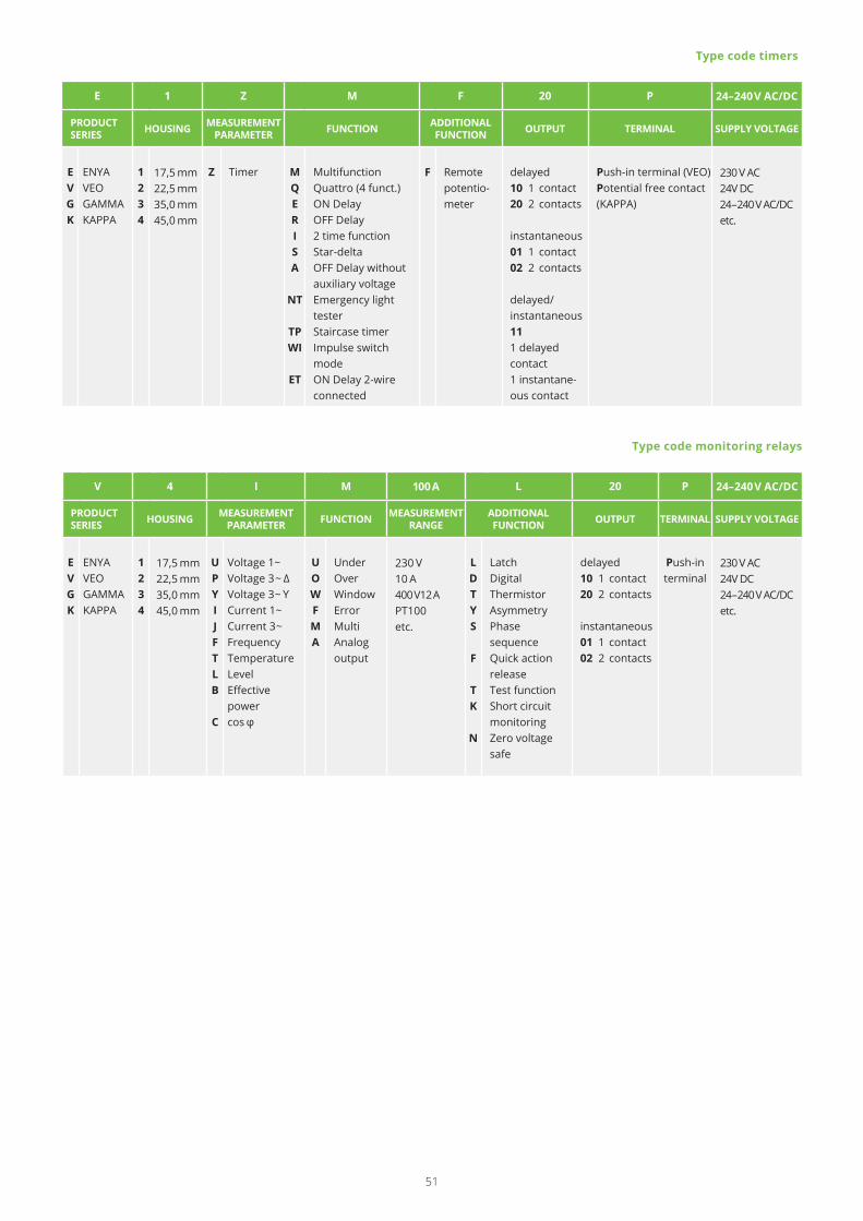
V 4 I M 100 A L 20 P 24–240 V AC/DC
PRODUCTSERIES HOUSING MEASUREMENT
PARAMETER FUNCTION MEASUREMENTRANGE
ADDITIONALFUNCTION OUTPUT TERMINAL SUPPLY VOLTAGE
EVGK
ENYAVEOGAMMAKAPPA
1234
17,5 mm22,5 mm35,0 mm45,0 mm
UPY IJFT L B
C
Voltage 1~Voltage 3~ Δ Voltage 3~ YCurrent 1~Current 3~FrequencyTemperatureLevelEffective powercos φ
UOWFMA
UnderOverWindowErrorMultiAnalog output
230 V10 A400 V12 APT100etc.
LDTYS
F
TK
N
LatchDigital ThermistorAsymmetryPhase sequenceQuick action releaseTest functionShort circuit monitoringZero voltage safe
delayed10 1 contact20 2 contacts
instantaneous01 1 contact02 2 contacts
Push-in terminal
230 V AC24V DC24–240 V AC/DC etc.
Type code monitoring relays
E 1 Z M F 20 P 24–240 V AC/DC
PRODUCTSERIES HOUSING MEASUREMENT
PARAMETER FUNCTION ADDITIONALFUNCTION OUTPUT TERMINAL SUPPLY VOLTAGE
EVGK
ENYAVEOGAMMAKAPPA
1234
17,5 mm22,5 mm35,0 mm45,0 mm
Z Timer MQERISA
NT
TPWI
ET
MultifunctionQuattro (4 funct.)ON DelayOFF Delay2 time functionStar-deltaOFF Delay without auxiliary voltageEmergency light testerStaircase timerImpulse switch modeON Delay 2-wire connected
F Remote potentio- meter
delayed10 1 contact20 2 contacts
instantaneous01 1 contact02 2 contacts
delayed/instantaneous111 delayed contact1 instantane-ous contact
Push-in terminal (VEO)Potential free contact (KAPPA)
230 V AC24V DC24–240 V AC/DC etc.
Type code timers
51

TELE Haase Steuergeraete Ges.m.b.H.
Vorarlberger Allee 38Vienna, 1230Austria
Phone +43 1 614 74-400Email [email protected]
For contact data of your local distributor please visit http://www.tele-online.com/en/organization/distribution/ Art.nr.: 091113/V3
Your contact