Embed Size (px)
Citation preview
FPE-2019-31 September, 2019
Page 1 of 11
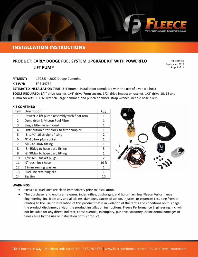
PRODUCT: EARLY DODGE FUEL SYSTEM UPGRADE KIT WITH POWERFLO
LIFT PUMP
FITMENT: 1998.5 – 2002 Dodge Cummins
KIT P/N: FPE-34754
ESTIMATED INSTALLATION TIME: 3-4 Hours – Installation completed with the use of a vehicle hoist
TOOLS REQUIRED: 1/4" drive ratchet, 1/4" drive 7mm socket, 1/2" drive impact or ratchet, 1/2" drive 10, 13 and 15mm sockets, 11/16” wrench, large hammer, and punch or chisel, strap wrench, needle nose pliers KIT CONTENTS:
Item Description Qty
1 PowerFlo lift pump assembly with float arm 1
2 Donaldson 3 Micron Fuel Filter 1
3 Single filter base mount 1
4 Distribution filter block to filter coupler 1
5 -8 to ¾”-16 straight fitting 2
6 ¾”-16 hex plug socket 1
7 M12 to -8AN fitting 1
8 -8, 45deg to hose barb fitting 3
9 -8, 90deg to hose barb fitting 1
10 1/8” NPT socket plugs 2
11 ½” push lock hose 16 ft
12 12mm sealing washer 1
13 Fuel line retaining clip 1
14 Zip ties 10
WARNINGS:
• Ensure all fuel lines are clean immediately prior to installation.
• The purchaser and end user releases, indemnifies, discharges, and holds harmless Fleece Performance Engineering, Inc. from any and all claims, damages, causes of action, injuries, or expenses resulting from or relating to the use or installation of this product that is in violation of the terms and conditions on this page, the product disclaimer, and/or the product installation instructions. Fleece Performance Engineering, Inc. will not be liable for any direct, indirect, consequential, exemplary, punitive, statutory, or incidental damages or fines cause by the use or installation of this product.

FPE-2019-31 September, 2019
Page 2 of 11
STEP 1: With the truck on a hoist, disconnect the fuel
filler hose and vent with a 7 mm socket.
STEP 2: Reaching over the top side of the tank,
disconnect the fuel lines and electrical connection for
the OEM sending unit.
STEP 3: Remove the cross-member located at the
front of the fuel tank. There will be 4, 15mm bolts to
remove.
PUMP INSTALLATION PROCEDURE:
FPE-2019-31 September, 2019
Page 3 of 11
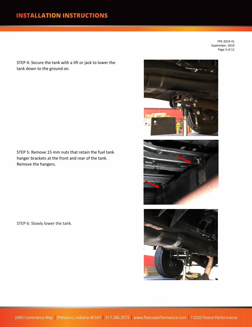
STEP 4: Secure the tank with a lift or jack to lower the
tank down to the ground on.
STEP 5: Remove 15 mm nuts that retain the fuel tank
hanger brackets at the front and rear of the tank.
Remove the hangers.
STEP 6: Slowly lower the tank.

FPE-2019-31 September, 2019
Page 4 of 11
STEP 7: SENDING UNIT REMOVAL With the tank on the ground, make note of the orientation of the OEM sending unit in the tank. The PowerFlo pump will be oriented in the same manner during installation. Using a strap wrench, or hammer along with a chisel or drift, rotate the sending unit’s retaining ring counter clockwise. Remove the retaining ring and remove the sending unit assembly from the tank. Have a bucket nearby to catch fuel from the OE unit when removed.

FPE-2019-31 September, 2019
Page 5 of 11
STEP 8: Remove the original gasket from the tank. STEP 9: Install the new gasket included in the kit into the fuel tank. Clean the original retaining ring of debris and prepare it for re-use onto the new PowerFlo pump.

STEP 10: Install the fuel level float arm onto the PowerFlo lift pump by gently clipping the arm into the fuel level sensor. With the pump resting on a flat surface, press down on the cap to simulate the installed the position of the cap - move the float arm up and down and ensure that the arm does not contact the pump wires or fuel tubes in the full up or full down position. If the tubes or wires contact the float arm, this will affect the fuel gauge reading. Check and confirm clearance before installing. STEP 11: Install the PowerFlo pump assembly into the tank. Check that the gasket is fully seated. STEP 12: Ensure proper orientation of the pump and fitting by matching the orientation of the original sending unit. Reinstall the retaining ring and tighten using a hammer and punch or a strap wrench by rotating it clockwise to the fully engaged position. NOTE: Use caution when installing the pump to not damage the float arm. DO NOT rotate the pump once installed in the tank, you may damage the float arm or sending unit – align the pump before you place it into the tank.
FPE-2019-31 September, 2019
Page 6 of 11
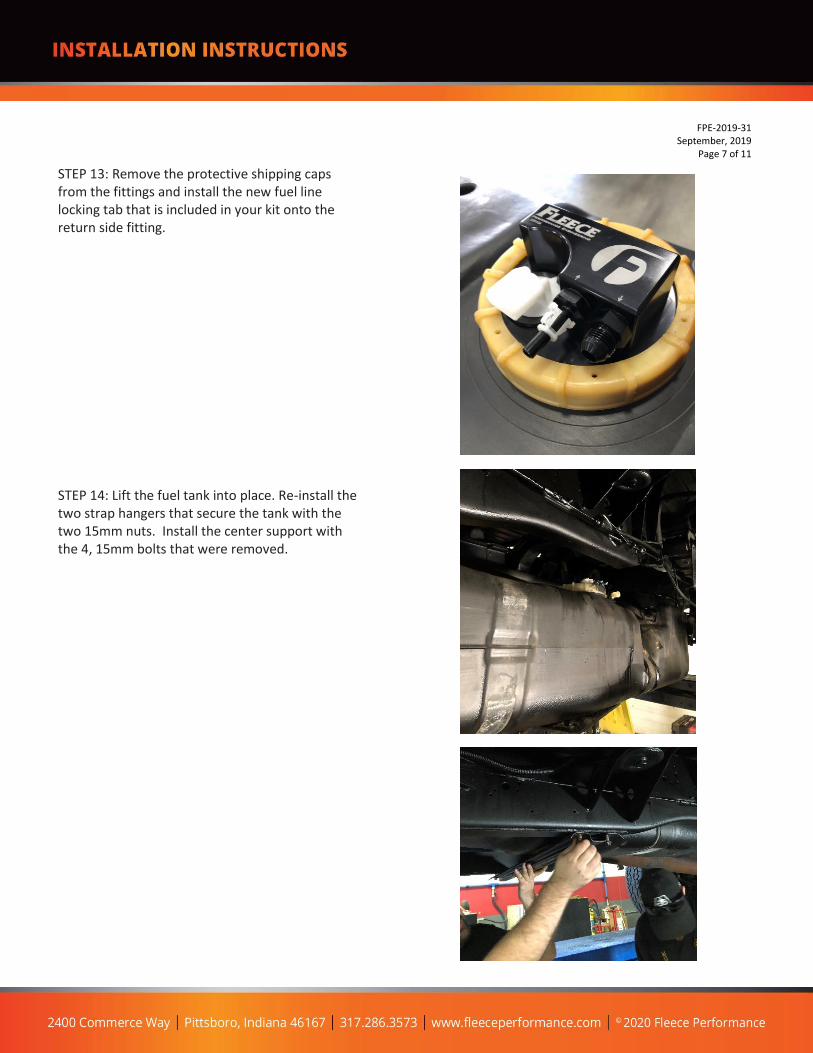
STEP 13: Remove the protective shipping caps from the fittings and install the new fuel line locking tab that is included in your kit onto the return side fitting. STEP 14: Lift the fuel tank into place. Re-install the two strap hangers that secure the tank with the two 15mm nuts. Install the center support with the 4, 15mm bolts that were removed.
FPE-2019-31 September, 2019
Page 7 of 11

STEP 15: With the tank mounted in place, access the top side of the tank from the rear wheel-well and make the fuel line connections at the sending unit. STEP 16: ROUTE FLEECE HARNESS TO THE ENGINE BAY Route the Fleece harness along the frame rails to the engine bay and battery. Route the harness in a manner that it will not interfere with any moving parts and retain it with zip ties. Mount or secure the relay in the engine bay. STEP 17: BATTERY CONNECTIONS Run the orange fused line to the positive (+) terminal of the battery. Run the black line to the negative (-) terminal of the battery. IMPORTANT: Never use a higher rated fuse than provided with the harness. If you experience a blown fuse always troubleshoot the problem before replacing the fuse. A blown fuse can be an indication of a short to ground in the harness, the relay, or inside the pump assembly.
FPE-2019-31 September, 2019
Page 8 of 11

STEP 18: SWITCHED POWER Connect the switched power lead for the PowerFlo pump to the OE pump signal line, located near the starter. **NOTE – If the control signal for the PowerFlo is wired to an ignition source instead of the OE signal line from the ECU you may encounter hard start issues.
STEP 19: From the driver’s side rear wheel-well, connect the electrical wiring harness to the PowerFlo lift pump connector. STEP 20: Add sufficient fuel back into the tank to submerge the pump bucket. CAUTION: Never run the pump dry or without fuel in the tank, damage will occur to the pump.
FPE-2019-31 September, 2019
Page 9 of 11

FILTER BLOCK AND PLUMBING:
To injection pump feed
(use new sealing washer)
To PowerFlo Lift
Pump Outlet
Cut hose to length for
routing from lift pump
to filter block
Spare outlet port – use
o-ring fitting to block-
off if not utilized
Two sensor outlet ports.
Use thread sealant on
all NPT fittings
Cut hose to length
for routing from
filter block to the
VP44 pump
FPE-2019-31 September, 2019
Page 10 of 11

.
FPE-2019-31 September, 2019
Page 11 of 11
FILTER BLOCK AND PLUMBING INSTRUCTIONS: STEP 1: If equipped, remove the stock fuel bowl from the engine bay. Disconnect electrical connectors for the Water in Fuel Sensor and Heater. STEP 2: Disconnect fuel lines STEP 3: Remove the fuel bowl that is retained with two 10 mm bolts. Retain the two bolts to mount the Fleece filter block in the same location. STEP 4: Install all fittings and new filter onto the Fleece filter block. Mount the filter block in the same location as the OE fuel bowl using the two 10 mm bolts that were removed during the fuel bowl removal. STEP 5: Route the fuel line from the fuel tank to the filter block housing. Retain the fuel line to the chassis using zip ties. Avoid routing the line near moving components. Install a 45 degree pushlock fitting at either end of the hose. STEP 6: Install the new 12mm sealing washer and 12mm to -8AN fitting onto the VP44 pump. Ensure that the original sealing washer has been removed from the pump surface. STEP 7: Route the fuel hose from the filter block to the VP44. Use the 90 deg pushlock fitting on VP44 end and a 45 deg pushlock fitting on the filter block end. STEP 8: Bleed the fuel system all the way to the injectors. STEP 9: Start the engine and check for leaks.

![2014 Dodge Avenger - Dealer Inspirebrochures.dealerinspire.com/2014/dodge/avenger.pdf · travel link [2] brings local and national weather forecasts, fuel prices for local gas stations,](https://img.dokumen.tips/doc/110x75/5e2f52305fc78110a4352046/2014-dodge-avenger-dealer-travel-link-2-brings-local-and-national-weather-forecasts.jpg)