Embed Size (px)
Citation preview

Product Catalogue and Technical Handbook
Grated trench drainage systems

The ACO Group
Founded in 1946, the ACO Group
manufactures products for the
building and construction industry.
Today, ACO employs over 3,200
people world-wide and has sales and
manufacturing operations in more
than 28 countries.
ACO is the world leader and pioneer
of modular grated trench drain
systems. ACO drainage systems are
used in a variety of applications from
domestic environments to airports.
ACO products have been used at
many prestigious locations, including
Olympic stadiums, since 1972.
3
05/1
7/04
Innovators ACO is the market leader in modulargrated trench drain systems. ACO Drainis manufactured at the company’s mod-ern manufacturing facility in Sydney.
ACO Drain offers the most comprehen-sive range of grated trench drain solu-tions for every application. ACO Drainproducts come in a variety of widths,depths, and load ratings, with grates tosuit.
In conjunction with a comprehensive,quality product range, ACO supports itsbusiness with stocking distributors, tech-nical sales support and world class cus-tomer service.
Surface Drainage
6 Surface drainage options
8 Product selection criteria
10 Grated trench drain hydraulics
16 Loadings
20 Material data
22 End user requirements
Standard Products
24 KlassikDrain - K100, KS100, K200, KS200, K300, KS300
42 PowerDrain - S100K, S200K, S300K
56 Universal Junction Pit - Series 600
Problem Solving Products
58 SlabDrain - H100K, H100KS, H200K, H200KS, H300K, H300KS
66 Brickslot
68 Membrane Drain
70 MiniKlassik
Technical Support and Other Information
74 Trench hydraulics service
75 Grate hydraulics service
76 Layout & scheduling service
78 Ponding analysis
79 Chemical resistance
80 Construction and installation
84 Installation diagrams
86 Specification clauses
88 Part number listing
90 Glossary
91 Channel request form
4 5
www.acoaus.com.au
Key
up to D up to G
Limited Small
Grates comply with AS 1428.2 Design for Access & Mobility
Load class
AS 1428.2 compliant
Grate options Wide
Contents
Slots/opening of less than or equal to 7mm in widthHeelguard

www.acoaus.com.au
7
Surface Drainage
6
www.acoaus.com.au
� Uneven, undulating appearance� Complex, multiple grades to design
and construct � Deeper ground excavation due to pipe
depths� Higher risk of ponding� Pipes prone to blocking and failure� Maintenance can be difficult and costly
as access to pipe work is restricted� Possible interference with other
services, e.g., electrical, sewage, etc.
Options for dealing with surface drainage
Surface drainage is important.
Whether frequent light rainfall oroccasional heavy downpours, surfacedrainage is necessary to prevent damageto pavement or property, and reducessafety hazards caused by ponding.Surface drainage is designed to:
� Reduce ponding (standing water)� Reduce slip hazards and subsequent
injury� Protect and extend life of pavements� Protect property from flood damage � Reduce inconvenience to public users� Reduce hydroplaning on roads
Options available:
� Ignore it (overland flow)
� Open swale
� Grated pits
� Grated trench drains
For solid pavements the first two are notideal. Grated pits or trench drains are themost viable solutions.
� Neat linear appearance� Simple grades to design and construct� Easy to install - shallower excavation
and easy grading of pavement� Continuously intercepts water along its
length and provides superior drainage � Minimal underground pipes� Maintenance is quick and easy as
trench is at the surface and easier toaccess
� On level pavements, can be used tocontain spills or restrict runoff
Water Sensitive UrbanDrainage Design (WSUD)
Sustainable drainage is an element of the‘Hydrological Cycle’. It is the collection ofrainwater, its treatment and, ultimately, itsreuse.
The process involves capturing water run-off, that may or may not containpollutants, so it can be dealt with in acontrolled manner. The water can then betreated, stored for future use, ortransported to receiving waterways. Thistransfer of water should come at a lowcost, and cause minimal damage anddanger to the environment.
Surface drainage can be used whererainwater has collected on paved areasfor the ‘capture’ phase of this process.
Grated trench drainage
Grated pits
Grated trench drains are ideal for thecapture and collection of storm water run-off. They form a barrier to preventrainwater run-off flowing onto the softlandscaping where collection is moredifficult. This is of particular importance ifthe risk of contamination is high, such asin highway and petrol station applications.
ACO provides a wide range of trenchdrains to meet the hydraulic needs of anyWSUD design.
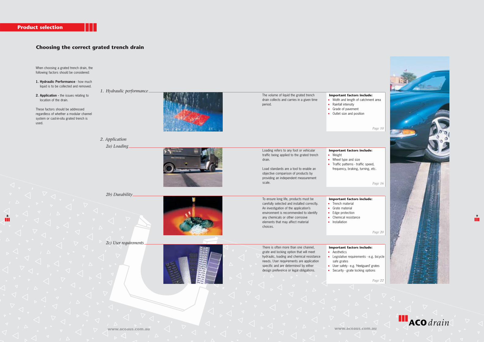
1. Hydraulic performance
2. Application
2a) Loading
2b) Durability
2c) User requirements
Product selection
8 9
www.acoaus.com.auwww.acoaus.com.au
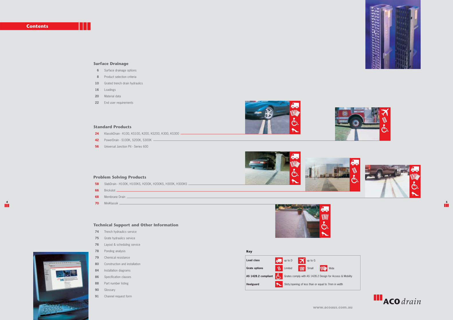
When choosing a grated trench drain, thefollowing factors should be considered:
1. Hydraulic Performance - how muchliquid is to be collected and removed.
2. Application - the issues relating tolocation of the drain.
These factors should be addressedregardless of whether a modular channelsystem or cast-in-situ grated trench isused.
Choosing the correct grated trench drain
Loading refers to any foot or vehiculartraffic being applied to the grated trenchdrain.
Load standards are a tool to enable anobjective comparison of products byproviding an independent measurementscale.
The volume of liquid the grated trenchdrain collects and carries in a given timeperiod.
Important factors include:� Width and length of catchment area� Rainfall intensity� Grade of pavement� Outlet size and position
Important factors include:� Weight� Wheel type and size� Traffic patterns - traffic speed,
frequency, braking, turning, etc.
There is often more than one channel,grate and locking option that will meethydraulic, loading and chemical resistanceneeds. User requirements are applicationspecific and are determined by eitherdesign preference or legal obligations.
Page 10
Page 16
Important factors include:� Trench material� Grate material� Edge protection� Chemical resistance� Installation
Page 20
To ensure long life, products must becarefully selected and installed correctly.An investigation of the application’senvironment is recommended to identifyany chemicals or other corrosiveelements that may affect materialchoices.
Important factors include:� Aesthetics� Legislative requirements - e.g. bicycle
safe grates� User safety - e.g. ‘Heelguard’ grates� Security - grate locking options
Page 22

www.acoaus.com.au
10 11
www.acoaus.com.au
Modelling hydraulic performance of trench drains
HYDROLOGICAL CYCLE
Non-uniform flow accounts for liquid beingcarried in a trench plus the constantaddition of liquid collected through thegrates along the trench run - lateralintake.
A characteristic of non-uniform flow is thatliquid velocity and height, change atsuccessive cross sections along thetrench.
To correctly model this situation,differential calculus is required; usuallycomputer modelling is used.
As a result of empirical testing, ACO hasdeveloped a computer program, ‘Hydro’,to model trench hydraulics.
ACO provides a complimentaryservice for trench hydraulics. Seepage 74 for details.
A traditionally used method of calculatingtrench hydraulics involves the use ofequations for steady uniform flow.
This approach is better suited for pipedesign where liquid velocity and heightremain constant along the pipe.
No allowance is made for lateral intake.
Steady, uniform flow can be used inculvert (open top) design for spillways orirrigation trenches. These culverts areused to carry liquids from one area toanother and do not account for lateralintake of liquids.
�� - inaccurate
�� - accurate
Non-uniform flow (Spatially Varied Flow)
Steady, uniform flow (Manning’s Theory)
1. Hydraulic Performance
Scenario:Rainwater falls over an area and runstowards, and collects at, any low point.
Conclusion:Grated trench drains intercept and collectsurface liquid. It is then carried to a pointwhere it can discharge into anunderground pipe system or culvert.

To calculate the correct size trench drain,catchment run-off must be calculated.
� Catchment area - length xwidth of pavement
� Rainfall intensity in mm per hour
� Run-off coefficient - ie. pavementmaterial, some surfaces absorbliquids e.g. block pavers
Once catchment run-off is calculated,other inflows, e.g. downpipes, can be added.
Refer to ‘Australian Rainfall and Run-off’ orAS/NZS 3500.3 - ‘Plumbing and DrainageCode’ for rainfall intensities.
Other factors that affect the transfer ofliquids include:
� Ground fall along trench %
� Position and size of outlet pipe
� Surface roughness of trench material.Manning’s coefficient of roughness -figures are available on page 21
� Pavement angle of approach to trench -this can affect grate hydraulics (steepslopes may cause bypass)
WL x
www.acoaus.com.au www.acoaus.com.au
The calculated run-off , is combinedwith the other factors above to determinethe correct size of trench. The trench sizeis specified by the clear opening andinvert depth - changing either or both ofthese will create a smaller or larger ‘flowarea’.
� Clear opening of trench is the normalspecified dimension, e.g. 100mm,200mm, etc.
� Overall grate and outside trenchdimensions are misleading.
Q
1312
1. Hydraulic Performance
Catchment hydraulics - calculating run-off
Overall trench
Overall grate
Invert depth
Clear opening
Clear opening, orwidth, is often chosenin conjunction withstandard grate sizes.
Depth of trench canvary along its length ifslope is introducedinto the base of thetrench. Some factors,such as slab depth,can restrict thesedimensions.
Overall dimensionsdetermine the physicalfit of the trench in thelocation.
‘U’ shaped bottomshould be used. Thismaximises velocity ofliquids at low volumes.
Factors affecting trench run hydraulics
Slope is part of the equation - but not as amultiplier. Trench size is accurately calculated.
When slope is large, water depths are under-estimated. Trench size is under sized -resulting in flooding.
Effect of slope on trench hydraulic performance
Slope increases the velocity of liquidwithin the trench drain and thereforeimproves hydraulic efficiency. Slope canbe introduced by:
1. Existing pavement with natural fall.
2. Introduce a stepped configuration
3. Introduce slope along the base of thetrench run.
4. A combination.
2.
3.
Ground fall or slope
Steady Uniform flowUses Area x Velocity to estimate flow capacity. When there is little or minimal slope,velocity tends towards zero, and water depths are over-estimated. When there issignificant slope, steady uniform flow under-estimates the water depths in the trenchdrain.
1.
Neutral invert no ground fall
Neutral invert with ground fall
Sloped invert with ground fall
Stepped invert no ground fall
Zero slope
Small slope
Large slope
Slope is part of the equation - but not as amultiplier. Trench size is accurately calculated.
Slope ‘S’ is the multiplier in the equation(Q=(1/n) AR2/3 x S1/2). For flat gradientsslope is zero and water depths cannot becalculated, therefore trench cannot besized.
Slope is part of the equation - but not as amultiplier. Trench size is accurately calculated.
When slope is small, water depths are over-estimated - resulting in a larger, morecostly trench.
Non-uniform flowAccurately accounts for effect of slopeand run length. Models the accuratehydraulic performance of trench. Allowscorrect size of trench drain to be used.
Zero slope
Small slope
Large slope
I
D
C
E
F
G
L
I
DC
E
F
GW
C
D
Determining trench size
Q
Area available for flow
4. Combination
Q
www.acoaus.com.au
2. Clear opening
15
www.acoaus.com.au
14
1. Hydraulic Performance
Factors affecting trench run hydraulics
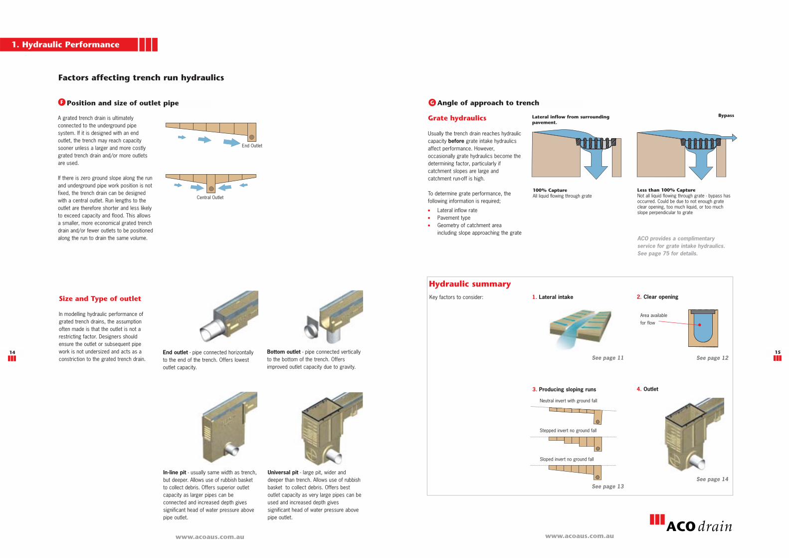
A grated trench drain is ultimatelyconnected to the underground pipesystem. If it is designed with an endoutlet, the trench may reach capacitysooner unless a larger and more costlygrated trench drain and/or more outletsare used.
If there is zero ground slope along the runand underground pipe work position is notfixed, the trench drain can be designedwith a central outlet. Run lengths to theoutlet are therefore shorter and less likelyto exceed capacity and flood. This allowsa smaller, more economical grated trenchdrain and/or fewer outlets to be positionedalong the run to drain the same volume.
End Outlet
Central Outlet
Position and size of outlet pipe
Size and Type of outlet
In modelling hydraulic performance ofgrated trench drains, the assumptionoften made is that the outlet is not arestricting factor. Designers shouldensure the outlet or subsequent pipework is not undersized and acts as aconstriction to the grated trench drain.
In-line pit - usually same width as trench,but deeper. Allows use of rubbish basketto collect debris. Offers superior outletcapacity as larger pipes can beconnected and increased depth givessignificant head of water pressure abovepipe outlet.
Bottom outlet - pipe connected verticallyto the bottom of the trench. Offersimproved outlet capacity due to gravity.
Universal pit - large pit, wider anddeeper than trench. Allows use of rubbishbasket to collect debris. Offers bestoutlet capacity as very large pipes can beused and increased depth givessignificant head of water pressure abovepipe outlet.
End outlet - pipe connected horizontallyto the end of the trench. Offers lowestoutlet capacity.
Lateral inflow from surroundingpavement.
100% CaptureAll liquid flowing through grate
Less than 100% CaptureNot all liquid flowing through grate - bypass hasoccurred. Could be due to not enough grateclear opening, too much liquid, or too muchslope perpendicular to grate
BypassGrate hydraulics
Usually the trench drain reaches hydrauliccapacity before grate intake hydraulicsaffect performance. However,occasionally grate hydraulics become thedetermining factor, particularly ifcatchment slopes are large andcatchment run-off is high.
To determine grate performance, thefollowing information is required;� Lateral inflow rate� Pavement type� Geometry of catchment area
including slope approaching the grate
Angle of approach to trenchF G
Hydraulic summary
Key factors to consider:
ACO provides a complimentaryservice for grate intake hydraulics.See page 75 for details.
Area available
for flow
3. Producing sloping runs
See page 12See page 11
See page 13See page 14
1. Lateral intake
Neutral invert with ground fall
Sloped invert no ground fall
Stepped invert no ground fall
4. Outlet
DIN 19580 / EN 1433 equivalentCLASS F
900kN
CLASS E
600kN
CLASS D
400kN
CLASS C
250kN
Contents
16 17
www.acoaus.com.auwww.acoaus.com.au
DIN 19580 / EN 1433
The only standard written specifically forgrated trench drains, and internationallyrecognised, is DIN 19580.
EN 1433 is superseding DIN 19580. Itaccounts for different widths of grates,with different size test blocks for differentsize channels.
EN 1433 tests products in exactly thesame method as DIN 19580 with thesame load categories, up to 900kN.
As with DIN 19580, EN 1433 offers testmethods for both the grate and channelbody. It accounts for both proof loadingand catastrophic failure.
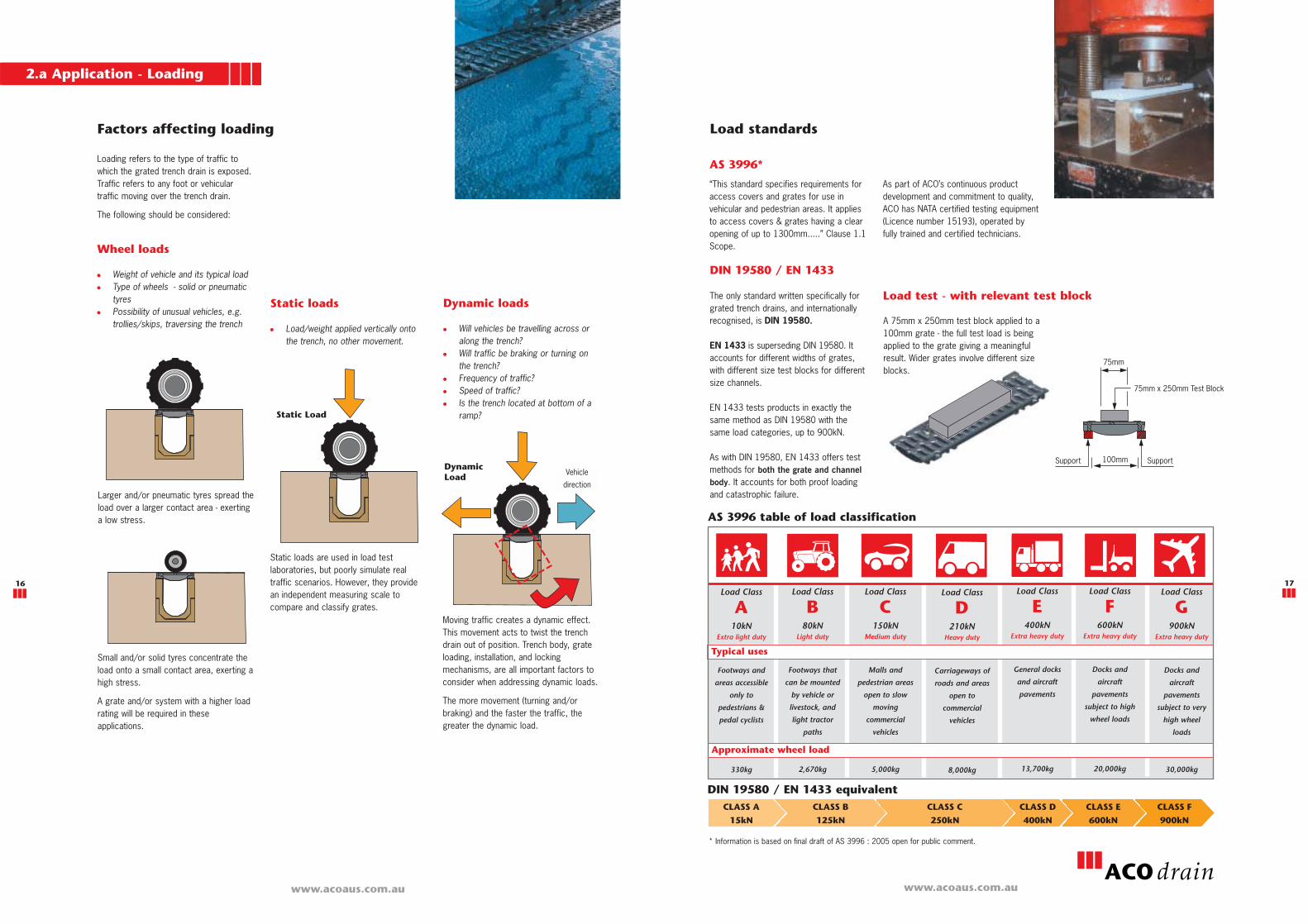
Factors affecting loading
Small and/or solid tyres concentrate theload onto a small contact area, exerting ahigh stress.
A grate and/or system with a higher loadrating will be required in theseapplications.
Larger and/or pneumatic tyres spread theload over a larger contact area - exertinga low stress.
Moving traffic creates a dynamic effect.This movement acts to twist the trenchdrain out of position. Trench body, grateloading, installation, and lockingmechanisms, are all important factors toconsider when addressing dynamic loads.
The more movement (turning and/orbraking) and the faster the traffic, thegreater the dynamic load.
Static loads are used in load testlaboratories, but poorly simulate realtraffic scenarios. However, they providean independent measuring scale tocompare and classify grates.
Static loads
� Load/weight applied vertically ontothe trench, no other movement.
Static Load
DynamicLoad
2.a Application - Loading
Dynamic loads
� Will vehicles be travelling across oralong the trench?
� Will traffic be braking or turning onthe trench?
� Frequency of traffic?� Speed of traffic?� Is the trench located at bottom of a
ramp?
Loading refers to the type of traffic towhich the grated trench drain is exposed.Traffic refers to any foot or vehiculartraffic moving over the trench drain.
The following should be considered:
Wheel loads
� Weight of vehicle and its typical load� Type of wheels - solid or pneumatic
tyres � Possibility of unusual vehicles, e.g.
trollies/skips, traversing the trench
Load standards
AS 3996*
“This standard specifies requirements foraccess covers and grates for use invehicular and pedestrian areas. It appliesto access covers & grates having a clearopening of up to 1300mm.....” Clause 1.1Scope.
75mm
75mm x 250mm Test Block
100mmSupport Support
Load test - with relevant test block
Load Class
A10kN
Extra light duty
Footways and
areas accessible
only to
pedestrians &
pedal cyclists
330kg
Load Class
B80kN
Light duty
Footways that
can be mounted
by vehicle or
livestock, and
light tractor
paths
2,670kg
Load Class
C150kN
Medium duty
Malls and
pedestrian areas
open to slow
moving
commercial
vehicles
5,000kg
Load Class
E400kN
Extra heavy duty
General docks
and aircraft
pavements
13,700kg
Load Class
F600kN
Extra heavy duty
Docks and
aircraft
pavements
subject to high
wheel loads
20,000kg
Load Class
G900kN
Extra heavy duty
Docks and
aircraft
pavements
subject to very
high wheel
loads
30,000kg
Typical uses
AS 3996 table of load classification
Load Class
D210kN
Heavy duty
Carriageways of
roads and areas
open to
commercial
vehicles
8,000kg
CLASS B
125kN
CLASS A
15kN
A 75mm x 250mm test block applied to a100mm grate - the full test load is beingapplied to the grate giving a meaningfulresult. Wider grates involve different sizeblocks.
As part of ACO’s continuous productdevelopment and commitment to quality,ACO has NATA certified testing equipment(Licence number 15193), operated byfully trained and certified technicians.
* Information is based on final draft of AS 3996 : 2005 open for public comment.
Approximate wheel load
Vehicle
direction

2.a Application - Loading
18
Load Class A - 10kNFootways and areas accessible only to
pedestrians & pedal cyclists
Load Class B - 80kNFootways that can be mounted by vehicle or livestock, and light
tractor paths
Load Class C - 150kNMalls and pedestrian areas open to slow moving commercial vehicles
Load Class D - 210kNCarriageways of roads and areas open to commercial vehicles
Load Class E - 400kNGeneral docks and aircraft pavements
Load Class G - 900kNDocks and aircraft pavements subject to very high wheel loads
Load Class F - 600kNDocks and aircraft pavements subject to high wheel loads

2.b Application - Durability
20 21
Edge protection
The exposed edge of the trench helpshold the grate in position and is subject tothe same loads as the grate. In additionto the effect of climate and weight ofvehicles, it may be exposed to impactfrom items being dropped or pulledacross it (e.g. skips). Once the edge fails,the grate will move and causecatastrophic failure.
Metal edges are most commonly used towithstand the abuse of traffic. Edgeprotection rails should be integrally cast-inor mechanically connected to the trenchbody. Edge rails that sit over existingstandard edges are often ill-fitting andsusceptible to failure.
Edge protection rails also provide someprotection during installation, particularlyif the wearing course of the pavement isnot applied immediately. Appropriate edgeprotection is particularly important inasphalt situations where rolling machinescan damage trench edges, leading topremature failure of the trench.
Modular trench drain systems aregenerally manufactured from eitherpolymer concrete, GRC (Glass fibreReinforced Concrete) or HDPE (HighDensity Polyethylene).
ACO Drain commercial grated trenchsystems are manufactured from polymerconcrete. Other materials do not meet thecompressive strength and thermalexpansion properties required incommercial and industrial applications.
ACO only uses HDPE as a trench materialfor domestic applications.
GRC
Glass fibre reinforced concrete (GRC) is amixture of cement, fine aggregate, water,chemical admixtures and alkali resistantglass fibres. GRC is predominantly usedfor building cladding panels.
Cement concrete
Cement concrete is Portland cementmixed with aggregates. Generally usedfor large cast-in-situ slab applications,where mass is required for structuralrigidity.
HDPE (Plastic)
High Density Polyethylene (HDPE) is themost common plastic used in trenchdrains. HDPE is a readily available,economical material that is easy tomould. HDPE has poor thermalproperties. A trench drain of 30m inlength, with an ambient temperaturechange of 24oC, can expand (or contract)up to 330mm more than the surroundingconcrete slab. The concrete surround willonly change minimally and cause thetrench to buckle or pull away from theconcrete.
Grates
Grates are manufactured from a variety ofmaterials. The most common are ductileiron, mild steel, stainless steel andplastic.
Grates need higher tensile properties thanthe trench body to withstand direct loads.Grates can be removed, changed oreasily replaced after installation, unlikethe trench drain body.
Polymer concrete
Polymer concrete is a versatile compositematerial produced by mixing mineralaggregates with a resin binding agent.The finished material has excellentmechanical and thermal properties andoffers good corrosion resistance to manychemicals. A maximum workingtemperature of 82oC is recommended.
For increased chemical resistance,vinylester polymer concrete is available.This consists of vinylester resin binderwith superior silica aggregate fillers.
See chemical resistance chart on page79.
Due to their structural rigidity, polymerconcrete trench drains, when installedproperly, can be used in a variety ofpavement types such as concrete,asphalt and brick pavers.
Material properties
HardenerResin
Aggregate Sand
Mechanical properties
Key: - Good - Acceptable - Poor
Cement Concrete Polymer Concrete GRC HDPE
www.acoaus.com.auwww.acoaus.com.au
Thermal properties
58MPa D-695
15MPa D-790
14MPa D-638
+0.31% D-570
223 cycles
FAILED modulus of
elasticity test C666
209.8 x 10⁻⁶ per oC
E831
WVT - 0.1392g/m2
1,592hrs
E96
After flame time :
390 seconds - fail
UL-94
1000hr exposure
no change G-154
FAILED TEST
n=0.010
Good
25MPa
3MPa
2MPa
<3%
300 cycles
maintain 80%
structural integrity
10 x 10-6 per oC
See water
absorption test
Non-combustible
Good depending
upon proper curing
n=0.013
Poor
96MPa C-579
27MPa C-580
21MPa C-307
+0.07% C-97
300 cycles
modulus of elasticity
95.1% C666
45.6 x 10⁻⁶ per oC
E831
WVT 0.0364g/m2 -
1,592hrs
E96
Flame spread : 0
Smoke density : 5
E84
2000hr exposure no
change G-153
n=0.011
Good
50MPa
12MPa
5.5MPa
12%
modulus of
elasticity
unchanged
20 x 10-6 per oC
1 x 10⁻⁴ gm/s.MN
Non combustible
Ignitability: P
Fire propagation: 0
Flame spread : 1
BS476
Similar to cement
concrete. UV stable
n= 0.012
Poor - better than
cement concrete
Surface properties
Compressive strength
The trench body is subject to compressive loads in
use and needs to withstand the specified load.
Flexural strength
Affects site handling and when trench body is in
areas where encasement and soils are suspect.
Tensile strength
Not generally required in trench bodies, but relevant
to grates. Used as material measurement.
Water absorption
The trench is designed to carry and collect liquids
without contaminating surrounding soil/encasement.
Freeze-thaw
Inability to withstand freeze-thaw cycles causes
surface spoiling and leads ultimately to trench failure.
Coefficient of expansion/contraction
Excessive movement between trench and
encasement materials creates unwanted stresses
which may lead to failure.
Water vapour transmission
WVT is measurement of water vapour flow through a
material. Passage of water vapour may be critical in
some instances.
Surface burning
Trench systems are often used around petrol
stations, chemical processing and interior
applications and may be subject to fire. They should
be non-flammable and not give off fumes or smoke.
Weathering
The majority of trench drains are used in exterior
applications. Ability to withstand adverse weather
will ensure long service life (erosion, UV degradation
etc).
Coefficient of friction (Manning’s)
Any degree of friction will affect liquid flow to some
extent, therefore the lowest value is desirable.
Chemical resistance
Trench may be used for liquids other than water and
in such circumstances, needs to be resistant to a
variety of mediums. See page 79 for details.
Cement concrete values obtained from AS 3600 and SA HB64 Guide to Concrete Construction (Cement & Concrete Assoc. of Australia)Polymer concrete values obtained from experimental data using ASTM testing proceduresGRC values obtained from Design, Manufacture & Installation of Glass Reinforced Concrete (GRC Industry Group of NPCAA)HDPE values obtained from experimental data using ASTM testing procedures
1. Aesthetics
2. Legislative requirements
3. User safety
4. Grate security
2.c Application - User requirements
22 23
www.acoaus.com.auwww.acoaus.com.au
The Australian Access andMobility requirements are setout in AS 1428.2 Clause 9 (c)
‘If gratings are located in a walking surface,they shall have spaces not more than13mm wide and not more than 150mmlong. If gratings have elongated openings,they shall be placed so that the longdimension is transverse to the dominantdirection of travel’.
The grate is the most visible part of thetrench drain and aesthetically the mostimportant.
Grates can be selected to ‘blend’ into thepavement, or used as a feature, orperimeter border.
Once hydraulics, loading and chemicalresistance requirements are met, the decisionis based on visual or cost preferences.
� Grate materials - stainless steel, ductileiron and plastic can all offer excellentaesthetics.
� Grate slot patterns - perforated,slotted, mesh and decorative patternsare available.
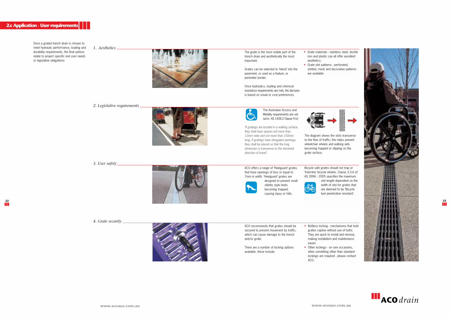
ACO recommends that grates should besecured to prevent movement by traffic,which can cause damage to the trench and/or grate.
There are a number of locking optionsavailable, these include:
Bicycle safe grates should not trap or‘tram-line’ bicycle wheels. Clause 3.3.6 ofAS 3996 : 2005 specifies the maximum
slot length dependent on thewidth of slot for grates thatare deemed to be ‘Bicycletyre penetration resistant’.
ACO offers a range of ‘Heelguard’ gratesthat have openings of less or equal to7mm in width. ‘Heelguard’ grates are
designed to prevent smallstiletto style heelsbecoming trapped,causing injury or falls.
� Boltless locking - mechanisms that holdgrates captive without use of bolts.They are quick to install and remove,making installation and maintenanceeasier.
� Other lockings - on rare occasions,when something other than standardlockings are required - please contactACO.
The diagram shows the slots transverseto the flow of traffic; this helps preventwheelchair wheels and walking aidsbecoming trapped or slipping on thegrate surface.
Once a grated trench drain is chosen tomeet hydraulic performance, loading anddurability requirements, the final optionsrelate to project specific end user needsor legislative obligations: