Embed Size (px)
Citation preview

LECTRO Bus Way System
[Series LSB II / 300A - 6400A]

LECTRO Bus Way System
[Series LSB II/ 300A - 6400A]
Energy demand is ever growing...
we attempt to provide efficient distribution
of electrical power with minimum power loss
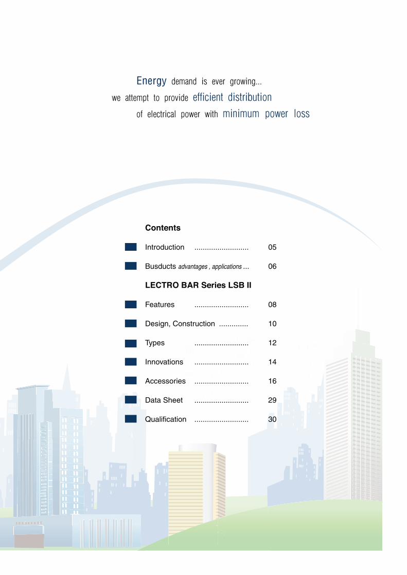
Contents
Introduction .......................... 05
Busducts advantages , applications ... 06
LECTRO BAR Series LSB II
Features .......................... 08
Design, Construction .............. 10
Types .......................... 12
Innovations .......................... 14
Accessories .......................... 16
Data Sheet .......................... 29
Qualification .......................... 30

04

Since 1980, Lectrobar has manufactured and installed thousands of meters of bus ducts.
State of the art ISO certified manufacturing facility has their products type tested by KEMA of Netherlands.
Lectrobar busducts are trusted for their high safety factor & long life span.
Lectrobar presents “Series LSB II” bus bar risers ranging from 300A upto 6400A.
At Lectrobar, you - the client, is the purpose for our pursuit of growth and most importantly, perfection.
Thank you for choosing us to partner your journey in creating effective, efficient and sustainable
power solutions.
Intro
du
ctio
nB
usd
ucts
Fe
atu
res
De
sig
nTyp
es
Inn
ova
tion
sA
cce
sso
ries
Da
ta S
he
et
Qu
alific
atio
n
Introduction
05

Advantages of busbar
over cables
Tapoffs make supply to addi-
tional loads easy at anytime
Can be easily relocated and
reused
Distribution may need changes,
bus ducts can accommodate
those changes at any time
Can be easily dismantled and
reused if required
Half the man-hours:
Installation requires only half
the time as compared to con-
ventional methods resulting in
considerable savings on instal-
lation costs
Zero shut downs:
continuity can be maintained as
servicing times are really short
and needs no operational shut-
downs
thanks to the sandwich de-
sign, busducts have very com-
pact cross sectional sizes and
occupy far less space com-
pared to cables
Less space
Cost savingsreusable, expandable
Busducts
06

The efficient method to feed
high rise buildings, distribution
to different floors is achieved
through convenient tapoffs
From the utility transformer to
the main switchboard
(service entrance), busduct
provides the most hassle free
feeding solution.
Normally used for feeding load
concentrated in one area, feed-
er busduct is the choice of con-
nection for a switch board to
switchboard tie / switchboard
to remote MCC / switchboard
to single load.
Basic function of power dis-
tribution through a busduct is
applied in different modes de-
pending on the spec i f i c
requirement of each installa-
tion.
Feeding multiple loads distrib-
uted through out a building/
manufacturing facility is easy
and time saving with busducts.
Conveniently placed tapoffs
ensure that plugs can be in-
stalled and removed safely in
no time. For higher ampere
ratings, ‘bolted on’ tap offs pro-
vide up to 1600A protection at
every joint.
Applications of
Busducts
Service entrance
and single loadVertical RiserMultiple Loads
Intro
du
ctio
nB
usd
ucts
Fe
atu
res
De
sig
nTyp
es
Inn
ova
tion
sA
cce
sso
ries
Qu
alific
atio
nD
ata
Sh
ee
t
07

copper bars
Safe and versatile design.
No need to separate or flare
the bars at the outlet
High short circuit withstand
for both feeder and plug-in.
Low impedance and low volt-
age drop
No flame smoke or gas
propagation in the housing -
chimney effect
Two Insulation layers used
Main insulation Teflon coated
fiberglass 2500C working
temperature and 5000V
breakdown
All insulation used better than
class H
Working temperature 50O C,
No deration required
Integral casing ground as
standard, 50% additional
ground bar, 100% ground bar
200%, 100% (Full), 50%
(Half) neutral available
No need for earth bar, the
aluminum housing ground
conductor is carried through
the joint
Since 1980 Lectrobar
has manufactured thousands of
meters installed busducts. State
of the art ISO certified manufac-
turing facility has their products
type tested by KEMA of Neth-
erlands. Lectrobar busducts are
trusted for their high safety factor
& long life span.
Meet the requirement of
IEC-439/1-2
Tested and approved by differ-
ent accredited laboratories
Fully type tested at KEMA
testing facility, Netherlands
Manufactured in an ISO
9001/2000 certified facility to
ensure highest quality control
More than thirty years in the
market
Oxygen free copper
High purity:
better or equal to 99.995%
High conductivity:
better than 99.5%
Good contact
Lectrobar Busducts - Unique features
True Sandwich for both
feeder and plug-in High Insulation Tested At
2500V for 1 Minute
Grounding and Neutral
www.transbar-me.com08
De
sig
nTyp
es
Inn
ova
tion
sA
cce
sso
ries
Qu
alific
atio
nIn
trod
uctio
nF
ea
ture
s
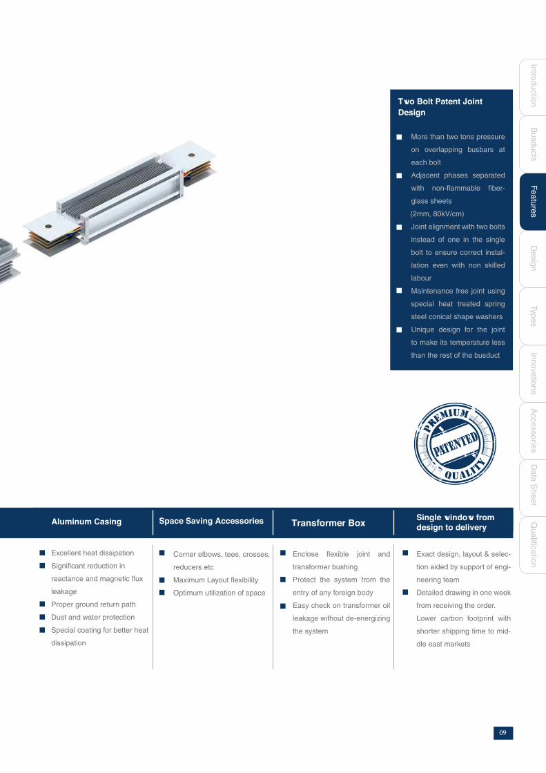
Corner elbows, tees, crosses,
reducers etc
Maximum Layout flexibility
Optimum utilization of space
Enclose flexible joint and
transformer bushing
Protect the system from the
entry of any foreign body
Easy check on transformer oil
leakage without de-energizing
the system
Exact design, layout & selec-
tion aided by support of engi-
neering team
Detailed drawing in one week
from receiving the order.
Lower carbon footprint with
shorter shipping time to mid-
dle east markets
Excellent heat dissipation
Significant reduction in
reactance and magnetic flux
leakage
Proper ground return path
Dust and water protection
Special coating for better heat
dissipation
Bu
sd
ucts
Single window from
Two Bolt Patent Joint
Design
More than two tons pressure
on overlapping busbars at
each bolt
Adjacent phases separated
with non-flammable fiber-
glass sheets
(2mm, 80kV/cm)
Joint alignment with two bolts
instead of one in the single
bolt to ensure correct instal-
lation even with non skilled
labour
Maintenance free joint using
special heat treated spring
steel conical shape washers
Unique design for the joint
to make its temperature less
than the rest of the busduct
Aluminum Casing Space Saving Accessories Transformer Box
Da
ta S
he
et
www.transbar-me.com 09

Lectrobar busducts have a sandwich type non-ven-
tilated configuration. The non-ventilated housing
design excludes potential points of penetration by
moisture and dust.
Busbars for plug-in applications, have full size
welded conductor tabs. This design extends the
contact surfaces outside of the busduct casing and
into the plug-in outlet, maintaining a true sandwich
design throughout the entire busduct length for
both feeder and plug-in busduct. This will eliminate
the need to seperate or flare the conductor bars at
the plug-in opening.
Maintaining a true sandwich design eliminates
potential pathways for the propagation of flame,
smoke and gas through the busduct casing, com-
monly referred to as the ‘chimney effect’. The sand-
wich structure with low impedance ensures low
voltage drop and thus enables the cost-effective
transmission of large amount of power even at long
distances.
Lectro bars are fabricated from high strength pure
electrolytic copper (99.99% with conductivity ~ 100%)
tin coated with suitable cross section. Tin coating pro-
vides high conductivity, surface protection and good
contact.
Shown is a section of Lectro bus duct insulation con-
sisting of two different insulation materials. Conduc-
tors are insulated with Teflon Coated Fiberglass films
(10 mil* thickness, 5000 V, 250OC) and layered with
fiber glass sheets. After assembly all the bars are
wrapped together with polyester tape. The result is an
insulation system that is virtually impervious to the
stress of normal operation. The insulation system is
tested after assembly with 2500 volt for one minute.
This test is intended to confirm the integrity of the in-
sulation system and helps ensure the highest qual-
ity bus duct possible. All the insulation materials are
rated as class H (minimum) non-flammable hence no
internal fire barrier is needed. Upon request the bars
can be insulated with cycloaliphatic epoxy resin class
B 130OC.
Busbar and insulation
Tin Plated Copper
Teflon Coated Fiberglass
Fiberglass sheets
Polyester Tape
Design & Construction
10

Lectrobar is constructed with extruded aluminum
profile. The non -magnetic aluminum housing ensures
excellent heat dissipation, a significant reduction in reac-
tance and magnetic flux leakage. Both the new casing de-
sign and the special casing coating ensures the best heat
dissipation possible from the system. This allows the sys-
tem to work without derating upto 50oC. Standard casing
is IP54. On request IP55, IP65 and IP67 casings can also
be supplied.
Aluminum casing provide an excellent ground re-
turn path. DC resistance /meter of the casing is less than
0.03 milliohm.
Hence integral housing ground is standard and provides
full cross section grounding .The system ground con-
tinuity is maintained through each joint by the ground
path end blocks and joint covers. In addition, the housing
ground conductor is carried through the joint. This de-
sign ensures that the integrity of the ground path is main-
tained by the same mechanical pressure used to main-
tain the continuity of the conductive path (Casing tested
as earth at KEMA Netherlands). An internal ground bus
adds no benefit with this method .It adds only unneces-
sary cost to the system. However, for applications where
the clients insist on 50% or 100% earth bar, Lectro can
provide it as an optional.
Ampere rating(A) Code X (mm) Y (mm Weight (Kg)
300
450
700
800
1000
1300
1600
2250
2500
3200
3500
4800
4000
5000
6400
78
90
110
140
160
180
183
325
370
490
550
550
140
140
140
140
140
140
140
140
140
140
140
140
4.5
7.0
9.4
13.5
16.5
21.3
27.0
35.6
43.0
53.4
64.0
76.9
LSBIIC3FNHFI030SL3
LSBIIC3FNHFI045SL3
LSBIIC3FNHFI070SL3
LSBIIC3FNHFI080SL3
LSBIIC3FNHFI100SL3
LSBIIC3FNHFI130SL3
LSBIIC3FNHFI160SL3
LSBIIC3FNHFI225SL3
LSBIIC3FNHFI250SL3
LSBIIC3FNHFI320SL3
LSBIIC3FNHFI350SL3
LSBIIC3FNHFI480SL3
LSBIIC3FNHFI400SL3
LSBIIC3FNHFI500SL3
LSBIIC3FNHFI640SL3
652
732
140
140
71.2
98.2
732 140 85.3
De
sig
nF
ea
ture
sTyp
es
Inn
ova
tion
sA
cce
sso
ries
Qu
alific
atio
nIn
trod
uctio
n
Design & Construction
Bu
sd
ucts
Da
ta S
he
et
11

300 A, 450A, 700A, 800A, 1000A
Standard length 3000 mm
1300A & 1600A 2250A & 2500A 3200A & 3500A & 4800A 4000A & 5000A & 6400A
300A LSBIIC3FNHFI030SL3
450A LSBIIC3FNHFI045SL3
700A LSBIIC3FNHFI070SL3
800A LSBIIC3FNHFI080SL3
1000A LSBIIC3FNHFI100SL3
1300A LSBIIC3FNHFI130SL3
1600A LSBIIC3FNHFI160SL3
2250A LSBIIC3FNHFI225SL3
2500A LSBIIC3FNHFI250SL3
3200A LSBIIC3FNHFI320SL3
3500A LSBIIC3FNHFI350SL3
4000A LSBIIC3FNHFI400SL3
4800A LSBIIC3FNHFI480SL3
5000A LSBIIC3FNHFI500SL3
6400A LSBIIC3FNHFI640SL3
Ampere Rating (A) Code
Feeder Busducts
12

Standard length 3000 mm
1300A & 1600A 2250A & 2500A 3200A & 3500A & 4800A 4000A & 5000A & 6400A
300A LSBIIC3FNHPI030SL3
450A LSBIIC3FNHPI045SL3
700A LSBIIC3FNHPI070SL3
800A LSBIIC3FNHPI080SL3
1000A LSBIIC3FNHPI100SL3
1300A LSBIIC3FNHPI130SL3
1600A LSBIIC3FNHPI160SL3
2250A LSBIIC3FNHPI225SL3
2500A LSBIIC3FNHPI250SL3
3200A LSBIIC3FNHPI320SL3
3500A LSBIIC3FNHPI350SL3
4000A LSBIIC3FNHPI400SL3
4800A LSBIIC3FNHPI480SL3
5000A LSBIIC3FNHPI500SL3
6400A LSBIIC3FNHPI640SL3
Ampere Rating (A) Code
300 A, 450A, 700A, 800A, 1000A
Plug - In Busducts
Fe
atu
res
Typ
es
Inn
ova
tion
sA
cce
sso
ries
Qu
alific
atio
nIn
trod
uctio
nB
usd
ucts
Da
ta S
he
et
De
sig
n
13
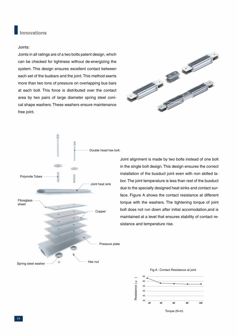
Joints:
Joints in all ratings are of a two bolts patent design, which
can be checked for tightness without de-energizing the
system. This design ensures excellent contact between
each set of the busbars and the joint. This method exerts
more than two tons of pressure on overlapping bus bars
at each bolt. This force is distributed over the contact
area by two pairs of large diameter spring steel coni-
cal shape washers. These washers ensure maintenance
free joint.
Joint alignment is made by two bolts instead of one bolt
in the single bolt design. This design ensures the correct
installation of the busduct joint even with non skilled la-
bor. The joint temperature is less than rest of the busduct
due to the specially designed heat sinks and contact sur-
face. Figure A shows the contact resistance at different
torque with the washers. The tightening torque of joint
bolt does not run down after initial accomodation,and is
maintained at a level that ensures stability of contact re-
sistance and temperature rise.
Double head hex bolt.
Polymide Tubes
Joint heat sink
Copper
Pressure plate
Hex nutSpring steel washer
Fibreglass
sheet
Innovations
65
60
55
50
45
4020 40 60 80 100
Torque (N-m)
Fig.A : Contact Resistance at joint
Resis
tance (
µ )
14

The bolts are insulated with Teflon coated fiberglass and
passed through the joint in a polyamide tube to elimi-
nate any problems arising from joint bolts. Join blocks
are used to ensure parallel joints of bars and complete
mechanical jointing using non-flammable, US made,
fiberglass sheet (2mm) with high dielectric strength
(200V/mil,80kV/cm). Double head bolts are used. One
head breaks at the required torque so no need for torque
wrenches. Also smart bolts can be used as optional for
critical sites. Using Smart bolts results in less fatigue
for installers, no repeated torque wrench calibration,
no sample re-tightening, no turn-of-nut confirmation re-
quired. Installers can easily identify and focus on loose
bolts to re-tighten. The ability to visually inspect fasten-
ers also creates safer working conditions particularly in
elevated structures and areas exposed to hazardous
materials.
Smart bolts *
* Upon request
300 1 90 180
450 1 90 180
700 1 100 240
800 1 120 250
1000 1 120 250
1300 1 120 250
1600 1 120 250
2250 2 120 250
2500 2 120 250
3200 3 120 250
3500 3 120 250
4000 4 120 250
4800 3 120 250
5000 4 120 250
6400 4 120 250
Ampere (A) No M(in mm) O(in mm)
Innovations
Fe
atu
res
Typ
es
Inn
ova
tion
sA
cce
sso
ries
Qu
alific
atio
nIn
trod
uctio
nB
usd
ucts
Da
ta S
he
et
De
sig
n
15

These accessories include :
1. Flat Elbows
2. Edgewise Elbows
3. Corner Flat Elbows
4. Corner Edgewise Elbows
5. Tees and Crosses
6. Transformer and Switchboard Flanges
7. Flexible joints
8. Spring Riser
9. Angle Hanger
10. End Closure
Complete line of ‘standard fittings’ or ‘made to fit’ accessories with wide varieties are available to meet every
application need.
Accessories
8
7
6
59
10
4
32
1
16

Ampere Rating (A) Code Min X,Y (mm)
300 LSBIIC3FNHFI030EF 250
450 LSBIIC3FNHFI045EF 250
700 LSBIIC3FNHFI070EF 350
800 LSBIIC3FNHFI080EF 350
1000 LSBIIC3FNHFI100EF 350
1300 LSBIIC3FNHFI130EF 400
1600 LSBIIC3FNHFI160EF 400
2250 LSBIIC3FNHFI225EF 550
2500 LSBIIC3FNHFI250EF 580
3200 LSBIIC3FNHFI320EF 700
3500 LSBIIC3FNHFI350EF 750
4800 LSBIIC3FNHFI480EF 750
4000 LSBIIC3FNHFI400EF 870
5000 LSBIIC3FNHFI500EF 950
6400 LSBIIC3FNHFI640EF 950
Accessories - Flat Elbow
Y
Y
Y
Y
Y
Y
Y
Y
Y
Y
Y
Y
Fe
atu
res
Typ
es
Inn
ova
tion
sA
cce
sso
ries
Qu
alific
atio
nIn
trod
uctio
nB
usd
ucts
Da
ta S
he
et
De
sig
n
17

Ampere Rating (A) Code Min X,Y (mm)
300 LSBIIC3FNHFI030EE 320
450 LSBIIC3FNHFI045EE 320
700 LSBIIC3FNHFI070EE 350
800 LSBIIC3FNHFI080EE 350
1000 LSBIIC3FNHFI100EE 350
1300 LSBIIC3FNHFI130EE 350
1600 LSBIIC3FNHFI160EE 350
2250 LSBIIC3FNHFI225EE 350
2500 LSBIIC3FNHFI250EE 350
3200 LSBIIC3FNHFI320EE 350
3500 LSBIIC3FNHFI350EE 350
4800 LSBIIC3FNHFI480EE 350
4000 LSBIIC3FNHFI400EE 350
5000 LSBIIC3FNHFI500EE 350
6400 LSBIIC3FNHFI640EE 350
Accessories - Edgewise Elbow
X
X
X
Y
Y
Y
X
X
Y
Y
Y
XX Y
X
XX Y
X Y
X Y
X
Y
X
Y
18
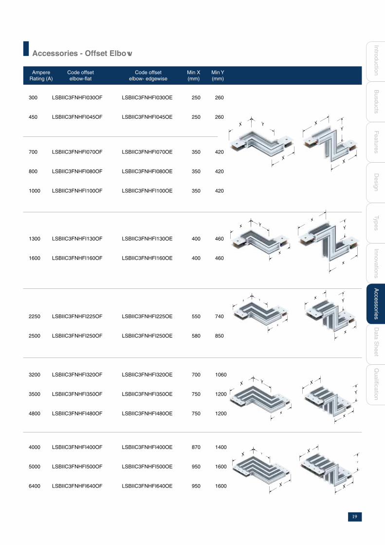
Accessories - Offset Elbow
300 LSBIIC3FNHFI030OF LSBIIC3FNHFI030OE 250 260
450 LSBIIC3FNHFI045OF LSBIIC3FNHFI045OE 250 260
700 LSBIIC3FNHFI070OF LSBIIC3FNHFI070OE 350 420
800 LSBIIC3FNHFI080OF LSBIIC3FNHFI080OE 350 420
1000 LSBIIC3FNHFI100OF LSBIIC3FNHFI100OE 350 420
1300 LSBIIC3FNHFI130OF LSBIIC3FNHFI130OE 400 460
1600 LSBIIC3FNHFI160OF LSBIIC3FNHFI160OE 400 460
2250 LSBIIC3FNHFI225OF LSBIIC3FNHFI225OE 550 740
2500 LSBIIC3FNHFI250OF LSBIIC3FNHFI250OE 580 850
3200 LSBIIC3FNHFI320OF LSBIIC3FNHFI320OE 700 1060
3500 LSBIIC3FNHFI350OF LSBIIC3FNHFI350OE 750 1200
4800 LSBIIC3FNHFI480OF LSBIIC3FNHFI480OE 750 1200
4000 LSBIIC3FNHFI400OF LSBIIC3FNHFI400OE 870 1400
5000 LSBIIC3FNHFI500OF LSBIIC3FNHFI500OE 950 1600
6400 LSBIIC3FNHFI640OF LSBIIC3FNHFI640OE 950 1600
Ampere
Rating (A)
Code offset
elbow-flat
Code offset
elbow- edgewise
Min X
(mm)
Min Y
(mm)
X Y
XX
X
Y
x
xY
x
x
Y
X
x
Y x
x
Y
X
x
YX
x
Y
X
XY
Y
X
X
Fe
atu
res
Typ
es
Inn
ova
tion
sA
cce
sso
ries
Qu
alific
atio
nIn
trod
uctio
nB
usd
ucts
Da
ta S
he
et
De
sig
n
19
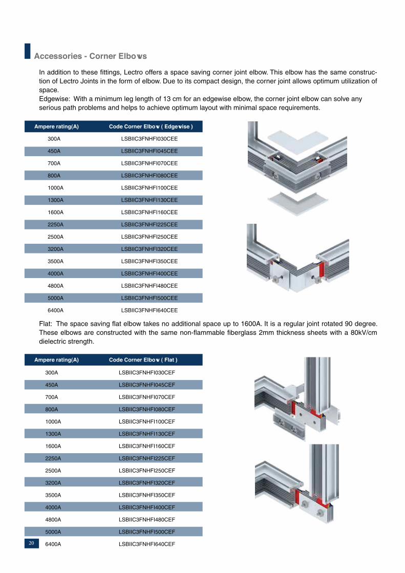
Accessories - Corner Elbows
In addition to these fittings, Lectro offers a space saving corner joint elbow. This elbow has the same construc-
tion of Lectro Joints in the form of elbow. Due to its compact design, the corner joint allows optimum utilization of
space.
Edgewise: With a minimum leg length of 13 cm for an edgewise elbow, the corner joint elbow can solve any
serious path problems and helps to achieve optimum layout with minimal space requirements.
300A LSBIIC3FNHFI030CEE
450A LSBIIC3FNHFI045CEE
700A LSBIIC3FNHFI070CEE
800A LSBIIC3FNHFI080CEE
1000A LSBIIC3FNHFI100CEE
1300A LSBIIC3FNHFI130CEE
1600A LSBIIC3FNHFI160CEE
2250A LSBIIC3FNHFI225CEE
2500A LSBIIC3FNHFI250CEE
3200A LSBIIC3FNHFI320CEE
3500A LSBIIC3FNHFI350CEE
4000A LSBIIC3FNHFI400CEE
4800A LSBIIC3FNHFI480CEE
5000A LSBIIC3FNHFI500CEE
6400A LSBIIC3FNHFI640CEE
300A LSBIIC3FNHFI030CEF
450A LSBIIC3FNHFI045CEF
700A LSBIIC3FNHFI070CEF
800A LSBIIC3FNHFI080CEF
1000A LSBIIC3FNHFI100CEF
1300A LSBIIC3FNHFI130CEF
1600A LSBIIC3FNHFI160CEF
2250A LSBIIC3FNHFI225CEF
2500A LSBIIC3FNHFI250CEF
3200A LSBIIC3FNHFI320CEF
3500A LSBIIC3FNHFI350CEF
4000A LSBIIC3FNHFI400CEF
4800A LSBIIC3FNHFI480CEF
5000A LSBIIC3FNHFI500CEF
6400A LSBIIC3FNHFI640CEF
Flat: The space saving flat elbow takes no additional space up to 1600A. It is a regular joint rotated 90 degree.
These elbows are constructed with the same non-flammable fiberglass 2mm thickness sheets with a 80kV/cm
dielectric strength.
Ampere rating(A) Code Corner Elbow ( Edgewise )
Ampere rating(A) Code Corner Elbow ( Flat )
20

Accessories - Tees and Crosses
Fe
atu
res
Typ
es
Inn
ova
tion
sA
cce
sso
ries
Qu
alific
atio
nIn
trod
uctio
nB
usd
ucts
Da
ta S
he
et
De
sig
n
Tees and busduct fittings for connection in three directions.
Crosses are suitable for connection in four directions. Crosses are applied when a bus run must branch off in three
directions in the same plane.
The minimum leg lengths (L) are shown in table.
Ampere (A) Code T-Elbow Edgewise Code T-Elbow Flat Code Cross Edgewise Code Cross Flat Length(mm)
300 LSBIIC3FNHFI030TE LSBIIC3FNHFI030TF LSBIIC3FNHFI030CE LSBIIC3FNHFI030CF 250
450 LSBIIC3FNHFI045TE LSBIIC3FNHFI045TF LSBIIC3FNHFI045CE LSBIIC3FNHFI045CF 300
700 LSBIIC3FNHFI070TE LSBIIC3FNHFI070TF LSBIIC3FNHFI070CE LSBIIC3FNHFI070CF 350
800 LSBIIC3FNHFI080TE LSBIIC3FNHFI080TF LSBIIC3FNHFI080CE LSBIIC3FNHFI080CF 350
1000 LSBIIC3FNHFI100TE LSBIIC3FNHFI100TF LSBIIC3FNHFI100CE LSBIIC3FNHFI100CF 380
1300 LSBIIC3FNHFI130TE LSBIIC3FNHFI130TF LSBIIC3FNHFI130CE LSBIIC3FNHFI130CF 400
1600 LSBIIC3FNHFI160TE LSBIIC3FNHFI160TF LSBIIC3FNHFI160CE LSBIIC3FNHFI160CF 450
2250 LSBIIC3FNHFI225TE LSBIIC3FNHFI225TF LSBIIC3FNHFI225CE LSBIIC3FNHFI225CF 550
2500 LSBIIC3FNHFI250TE LSBIIC3FNHFI250TF LSBIIC3FNHFI250CE LSBIIC3FNHFI250CF 580
3200 LSBIIC3FNHFI320TE LSBIIC3FNHFI320TF LSBIIC3FNHFI320CE LSBIIC3FNHFI320CF 700
3500 LSBIIC3FNHFI350TE LSBIIC3FNHFI350TF LSBIIC3FNHFI350CE LSBIIC3FNHFI350CF 750
4000 LSBIIC3FNHFI400TE LSBIIC3FNHFI400TF LSBIIC3FNHFI400CE LSBIIC3FNHFI400CF 870
4800 LSBIIC3FNHFI480TE LSBIIC3FNHFI480TF LSBIIC3FNHFI480CE LSBIIC3FNHFI480CF 750
5000 LSBIIC3FNHFI500TE LSBIIC3FNHFI500TF LSBIIC3FNHFI500CE LSBIIC3FNHFI500CF 950
6400 LSBIIC3FNHFI640TE LSBIIC3FNHFI640TF LSBIIC3FNHFI640CE LSBIIC3FNHFI640CF 950
Flat Edgewise
21
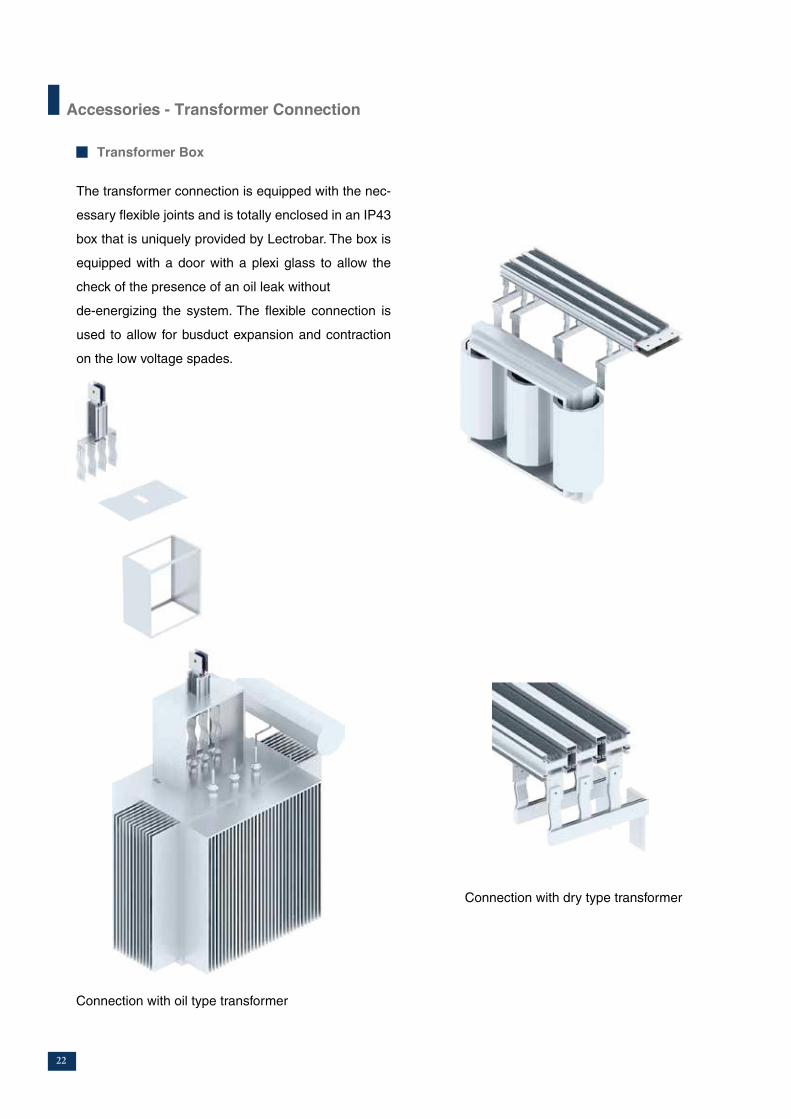
Accessories - Transformer Connection
Transformer Box
Connection with oil type transformer
Connection with dry type transformer
The transformer connection is equipped with the nec-
essary flexible joints and is totally enclosed in an IP43
box that is uniquely provided by Lectrobar. The box is
equipped with a door with a plexi glass to allow the
check of the presence of an oil leak without
de-energizing the system. The flexible connection is
used to allow for busduct expansion and contraction
on the low voltage spades.
22
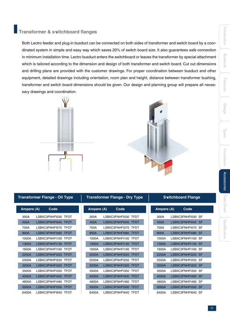
Both Lectro feeder and plug-in busduct can be connected on both sides of transformer and switch board by a coor-
dinated system in simple and easy way which saves 20% of switch board size. It also guarantees safe connection
in minimum installation time. Lectro busduct enters the switchboard or leaves the transformer by special attachment
which is tailored according to the dimension and design of both transformer and switch board. Cut out dimensions
and drilling plans are provided with the customer drawings. For proper coordination between busduct and other
equipment, detailed drawings including orientation, room plan and height, distance between transformer bushing,
transformer and switch board dimensions should be given. Our design and planning group will prepare all neces-
sary drawings and coordination.
300A LSBIIC3FNHFI030 TFOT
450A LSBIIC3FNHFI045 TFOT
700A LSBIIC3FNHFI070 TFOT
800A LSBIIC3FNHFI080 TFOT
1000A LSBIIC3FNHFI100 TFOT
1300A LSBIIC3FNHFI130 TFOT
1600A LSBIIC3FNHFI160 TFOT
2250A LSBIIC3FNHFI225 TFOT
2500A LSBIIC3FNHFI250 TFOT
3200A LSBIIC3FNHFI320 TFOT
3500A LSBIIC3FNHFI350 TFOT
4000A LSBIIC3FNHFI400 TFOT
4800A LSBIIC3FNHFI480 TFOT
5000A LSBIIC3FNHFI500 TFOT
6400A LSBIIC3FNHFI640 TFOT
Ampere (A) Code Ampere (A) Code Ampere (A) Code
300A LSBIIC3FNHFI030 TFDT
450A LSBIIC3FNHFI045 TFDT
700A LSBIIC3FNHFI070 TFDT
800A LSBIIC3FNHFI080 TFDT
1000A LSBIIC3FNHFI100 TFDT
1300A LSBIIC3FNHFI130 TFDT
1600A LSBIIC3FNHFI160 TFDT
2250A LSBIIC3FNHFI225 TFDT
2500A LSBIIC3FNHFI250 TFDT
3200A LSBIIC3FNHFI320 TFDT
3500A LSBIIC3FNHFI350 TFDT
4000A LSBIIC3FNHFI400 TFDT
4800A LSBIIC3FNHFI480 TFDT
5000A LSBIIC3FNHFI500 TFDT
6400A LSBIIC3FNHFI640 TFDT
300A LSBIIC3FNHFI030 SF
450A LSBIIC3FNHFI045 SF
700A LSBIIC3FNHFI070 SF
800A LSBIIC3FNHFI080 SF
1000A LSBIIC3FNHFI100 SF
1300A LSBIIC3FNHFI130 SF
1600A LSBIIC3FNHFI160 SF
2250A LSBIIC3FNHFI225 SF
2500A LSBIIC3FNHFI250 SF
3200A LSBIIC3FNHFI320 SF
3500A LSBIIC3FNHFI350 SF
4000A LSBIIC3FNHFI400 SF
4800A LSBIIC3FNHFI480 SF
5000A LSBIIC3FNHFI500 SF
6400A LSBIIC3FNHFI640 SF
Switchboard Flange
Fe
atu
res
Typ
es
Inn
ova
tion
sA
cce
sso
ries
Qu
alific
atio
nIn
trod
uctio
nB
usd
ucts
Da
ta S
he
et
De
sig
n
23

Panel Flange
300A 30 - - 500 280
450A 30 - - 500 280
700A 50 - - 500 300
800A 80 - - 500 300
1000A 100 - - 500 350
1300A 120 - - 500 350
1600A 120 - - 500 350
2250A 100 65 265 500 500
2500A 120 65 305 500 550
3200A 100 65 430 500 700
3500A 120 65 490 500 750
4800A 120 65 490 500 750
4000A 100 65 595 500 850
5000A 120 65 675 500 950
6400A 120 65 675 500 950
Ampere (A) B C D I J
Dimensions in mm Flange Panel Collar
B
B
B
B
B B
D
D
C
C C
B B B B
D
C C C
24
B
I
I
I
I
I
J
J
J
J
J

LSBIIC3FNHFI030TFOT
LSBIIC3FNHFI045TFOT
LSBIIC3FNHFI070TFOT
LSBIIC3FNHFI080TFOT
LSBIIC3FNHFI100TFOT
LSBIIC3FNHFI130TFOT
LSBIIC3FNHFI160TFOT
LSBIIC3FNHFI225TFOT
LSBIIC3FNHFI250TFOT
LSBIIC3FNHFI320TFOT
LSBIIC3FNHFI350TFOT
LSBIIC3FNHFI480TFOT
LSBIIC3FNHFI400TFOT
LSBIIC3FNHFI500TFOT
LSBIIC3FNHFI640TFOT
LSBIIC3FNHFI030TFDT
LSBIIC3FNHFI045TFDT
LSBIIC3FNHFI070TFDT
LSBIIC3FNHFI080TFDT
LSBIIC3FNHFI100TFDT
LSBIIC3FNHFI130TFDT
LSBIIC3FNHFI160TFDT
LSBIIC3FNHFI225TFDT
LSBIIC3FNHFI250TFDT
LSBIIC3FNHFI320TFDT
LSBIIC3FNHFI350TFDT
LSBIIC3FNHFI480TFDT
LSBIIC3FNHFI400TFDT
LSBIIC3FNHFI500TFDT
LSBIIC3FNHFI640TFDT
Fe
atu
res
Typ
es
Inn
ova
tion
sA
cce
sso
ries
Qu
alific
atio
nIn
trod
uctio
nB
usd
ucts
Da
ta S
he
et
De
sig
n
Accessories - Transformer Connection
300
450
700
800
1000
1300
1600
2250
2500
3200
3500
4800
4000
5000
6400
25

Accessories - Reducers
Non Protected Reducer
Lectro busduct is designed to expand as a load is ap-
plied and the temperature of the busbar increases. If
the installation can accept this movement, then no
expansion coupling is required. Generally horizontal
runs do not require expansion lengths. However, if
both ends of the busduct are fixed, normal expansion
is restricted. In this case expansion coupling will be
necessary. Expansion couplings are manufactured us-
ing a layered laminated flexible section bolted to the
adjacent copper conductors. Expansions are individu-
ally insulated within the truncking body and identified
by means of a label attached to the side of the expan-
sion length box.
Reducer boxes with circuit breakers or fuses are used
for protection and as a disconnecting means.
Reduction in bus capacity is made within the box .Min-
imum length of the protected reducer is 80cm.
Expansion coupling
Protected Reducers
Non-protected reducers are used to reduce the ca-
pacity of busduct without protection device. No pro-
tection is required where busduct is reduced in size
provided that the length of the smaller busduct is less
than 15m and has a current rating of at least 1/3 of
the larger busduct.The reduction is made by a patent
design joint to make the reduction in minimum space.
26

End closure Fixation and Hangers
Fe
atu
res
Typ
es
Inn
ova
tion
sA
cce
sso
ries
Qu
alific
atio
nIn
trod
uctio
nB
usd
ucts
Da
ta S
he
et
De
sig
n
Accessories
End closures terminate a busduct run and can be
used to close right or left ends. It is constructed from
thick fiberglass sheets laid between the busduct bars.
Vertical hangers: A spring suspension type is used
for vertical runs.This hanger equalizes the weight of
vertically mounted busduct along all supports. These
hangers compensate for expansion and contraction of
the busduct .At least one vertical hanger must be used
for each floor.
Feed units are used to supply power to the busduct.
The box is made from sheet steel containing either
connection strip, circuit breaker or fuses. However, it
is recommended to feed busducts over 1600A directly
from the distribution panel. The minimum length of the
feed unit depends on the size of cables entering the
box, but normally it is greater than 80cm.
A final fit section of busduct is typically an elbow or
a short length; left intentionally for later shipment. Its
purpose is to effectively manage the dimensional un-
certainties that may involve in busduct layout.
Feed Box
Horizontal hangers: Angle hanger
Hangers are provided for every 3 meters of horizon-
tally mounted busduct .The type of hanger supplied is
determined by the specific mounting requirements of
the busduct.
27

The tap -off boxes are made from sheet steel painted with
electrostatic paint or galvanized. Tap-off with breakers
have the following precautions to ensure safe operation.
A cover interlock to prevent opening while the tap-off is in the ON position.
An ON-OFF handle mounted on tap -off to operate the breaker without opening the cover.
A switch interlock prevents putting the device into op-eration when the cover is open.
A safety interlock prevents insertion or removal of the plug while in the ON position.
To ensure that the tap-off plugs are seated onto the bus-
duct, the box is equipped with a clamping mechanism.
This mechanism will draw the unit tight on to the busduct
housing as the installer tightens the clamps. The contact
resistance between plug pins and the tinned busbars is
constant even after years of operation due to the high
contact pressure.
Bolt-on tap-offs are used as power take-off up to 1600 A. When the required current is higher than the
capacity of the plug-in, tap-off unit bolts directly to the contact surfaces of the busbar joint. The unit can carry either
a circuit breaker or fuses.
Plug - in
Bolted on
Up to 160A
200A&250A
320A to 600A
800A
40
50
80
100
20
20
40
50
20
20
30
30
Rated Current
X (cm) Y (cm) Z (cm)
Accessories - Tap offs
28

700
25
52.5
120
25
122.5
49
96
102.9
103.8
400
99
412.1
360
150
390
Electrical Data Sheet
Description
Casing : Extruded Aluminium
Protection Degree (IP) : Standard - IP54, Optional - IP55, IP65, IP67
Rated Insulation Volltage (V) : 1000
Rated Operation Volltage (V) : upto 1000
Rated Impulse Volltage (kV) : 8
Frequency (Hz) : 50
*The value of the voltage drop is for distributed load.
For voltage drop in µ V/m multiply the table values by the actual current.
Shown values are line to line voltage drop.
** Calculated values, tested values are 40 kA for 800A 50 kA for 1000A,1300A & 1600A 75kA for 2000A, 2500A 100 kA for
3200A and higher.
Ampere Rating (A)
Short Circuit Current
Short circuit current for 1sec (kA)**
Peak Short Circuit (kA)
Characteristics under normal operation
Phase resistance (µ m)
Phase reactance (µ /m)
Phase impedance (µ /m)
Casing resistance (µ /m)
Voltage drop for distributed load*(µV/m)/A
Cos = 0.8
Cos = 0.9
Cos = 1.0
Characteristics under fault conditions
Phase to neutral resistance (µ /m)
Phase to neutral reactance (µ /m)
Phase to neutral impedance (µ /m)
Phase to earth resistance (µ /m)
Phase to earth reatance (µ /m)
Phase to earth impdence(µ /m)
300
15
30
400
32
401.5
72
294.9
324.7
346
1200
185
1214
1080
370
1142
450
20
40
240
30
241.7
68
181.6
198.2
207.6
800
159
815.6
720
255
763.8
800
40
84
75
23
78.4
31
63.8
67.1
64.8
308.2
89.9
321
357
202
410.2
1000
50
105
60
28.4
66.4
28
56.2
57.5
51.9
200
80
200
180
87
179.9
1300
60
132
50
25.8
56.3
19
48
48.7
43.2
198
58
206
116
75
138.1
1600
70
154
37.5
14.6
40.3
15.5
33.5
34.7
32.4
154
53
163
178
119
214
2250
80
176
30
13.5
32.9
14
27.7
28.5
25.9
100
47
110.5
90
51
103.4
2500
100
220
25
11.5
27.5
9.5
23.3
23.8
21.6
97
35
103
56
42
70
3200
130
286
20
9.1
22
9.5
18.5
19
17.3
67
31.4
74
60
34
96
3500
140
308
16.7
6.8
18
6.3
15
15.5
14.4
66
22.8
69.83
38.7
29.4
48.6
4000
150
330
15
6.7
16.4
7
13.8
14.2
12.9
50
27.6
57.1
45
30
54
5000
150
330
12.5
6
13.9
4.75
11.7
12
10.8
48.5
20.6
52.7
28
24.7
37.3
4800
150
330
12.5
6.8
14.22
6.3
12.18
12.32
10.81
49
25
56
35
28
46
6400
150
330
10
6
11.67
4.7
10
10.08
8.55
47
20
51
26
23
35
Fe
atu
res
Typ
es
Inn
ova
tion
sA
cce
sso
ries
Qu
alific
atio
nIn
trod
uctio
nB
usd
ucts
Da
ta S
he
et
De
sig
n
29
KEMA of Netherlands certified the complete
type tests on Lectrobar bus ducts.
The ratings of the busbars tested successfully range
from 300A to 6400A.
Lectrobar has its success attributed to their
culture of technical innovation and research. Stand-
ing testimony to that are the three Patents held by
Eng. Abed. One of them tested and approved by
Westinghouse laboratories and witnessed by UL.
Lectro has a clearly defined quality system
and policy . The system is religously understood and
implemented in all levels in the company .SGS inter-
national certification services audited this system to
certify fulfillment of ISO9001:2000 requirements.
A copy of quality manual can be forwarded upon re-
quest .
Patents
30
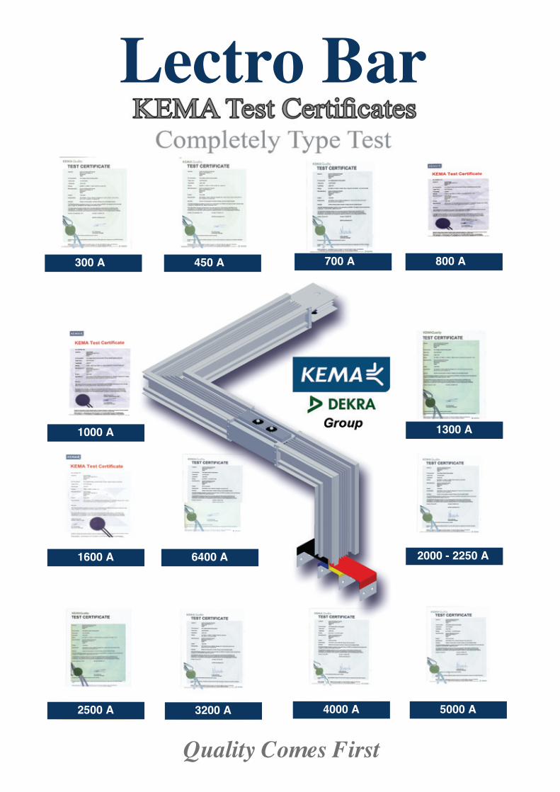
300 A
1000 A
1600 A
2500 A 3200 A 4000 A 5000 A
6400 A
1300 A
2000 - 2250 A
450 A 700 A 800 A
Quality Comes First
Lectro Bar

Lectro BarBorg El arab 3rd Industrial ZoneAlexandria, EgyptTel/Fax. +(203)4595955 - (203)4597955 (203)5222102 - (203)5221934 - (203)4593058www.lectroegypt.com