Embed Size (px)
Citation preview

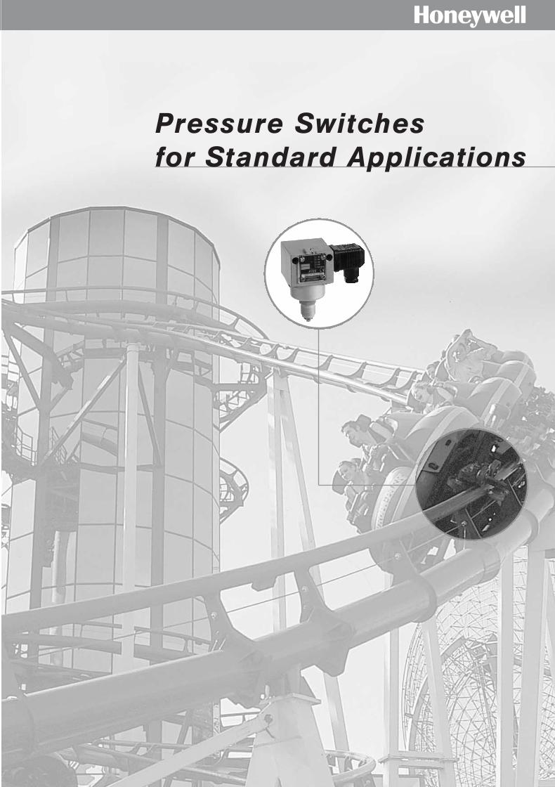
Pressure Switches
Pressure Transmitters
Thermostats
Temperature Transmitters
Solenoid Valves
Flow Monitors
Hf
F e a t u r i n g
Product Catalog
TÜV DVGW
ATEXZulassung inVorbereitung
01331_Product Catalog_02 19.02.2002 9:25 Uhr Seite 1

HYour connection to Fema
FEMA Schönaich E-mail Extension-Nr.
FEMA Controls Honeywell AG [email protected] (49) 70 31 6 37-02
Böblinger Strasse 17 Fax (49) 70 31 6 37-8 50
D-71101 Schönaich
Technical Questions Jürgen Berner [email protected] (49) 70 31 6 37-8 33
Robert Käshammer [email protected] (49) 70 31 6 37-8 24
Sales Support Monika Klingler [email protected] (49) 70 31 6 37-8 26
Ingrid Kirchenbauer [email protected] (49) 70 31 6 37-8 17
Zeljka Tosic [email protected] (49) 70 31 6 37-8 11
Customer Selma Solmaz [email protected] (49) 70 31 6 37-8 13
Service Zeljka Tosic [email protected] (49) 70 31 6 37-8 11
Product Franz Lutz [email protected] (49) 70 31 6 37-3 26
Management
Fema ControlsHoneywell AGPostfach 12 5471099 SchönaichBöblinger Straße 1771101 SchönaichPhone (49) 70 31 6 37-02Fax (49) 0 70 31 6 37-8 [email protected]/fema
(approx. 15 minutes) Freeway A81 direction Stuttgart/Böblingen. Take exit 23 “Böblingen-Sindelfingen”. Direction Böblingen to center (Zentrum). Follow the signs to “Nürtingen/Schönaich”.
(approx. 10 minutes) Freeway A81. Take exit 22 “Böblingen-Ost”.Turn left on the first traffic light. Follow the signs to Schönaich. In the traffic circle take the first exit and follow the main road.
To those, who are familiar with the area: Freeway A8 from direction Munich. Take exit 53 Stuttgart/Airport. Pass through Echterdingen/Steinenbronn to Schönaich.
How to find us:
01331_Product Catalog_02 19.02.2002 9:25 Uhr Seite 2
1
H
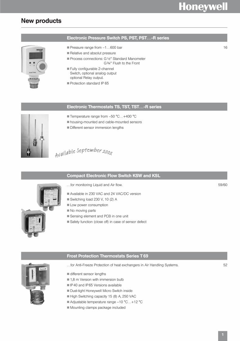
Electronic Pressure Switch PS, PST, PST…-R series
New products
Pressure range from –1…600 bar 16
Relative and absolut pressure
Process connections: G|HH Standard ManometerGHH Flush to the Front
Fully configurable 2-channel Switch, optional analog outputoptional Relay output.
Protection standard IP 65
Electronic Thermostats TS, TST, TST…-R series
Temperature range from –50 °C…+400 °C
housing-mounted and cable-mounted sensors
Different sensor immersion lengths
Available September 2002
Compact Electronic Flow Switch KSW and KSL
…for monitoring Liquid and Air flow. 59/60
Available in 230 VAC and 24 VAC/DC version
Switching load 230 V, 10 (2) A
Low power consumption
No moving parts
Sensing element and PCB in one unit
Safety function (close off) in case of sensor defect
Frost Protection Thermostats Series T 69
…for Anti-Freeze Protection of heat exchangers in Air Handling Systems. 52
different sensor lengths
1,8 m Version with immersion bulb
IP 40 and IP 65 Versions available
Dust-tight Honeywell Micro Switch inside
High Switching capacity 15 (8) A, 250 VAC
Adjustable temperature range –10 °C…+12 °C
Mounting clamps package included
01331_Product Catalog_02 19.02.2002 9:25 Uhr Seite 3

2
Solenoid Valves Series AV
New products
H
Single Stage Room & Duct Hygrostats H 6045 A and H 6120 A
…for monitoring humidity in air conditioning systems and climatic cabinets. 55
Humidity range 35…100 % r. H.
Single pole change over contact
Cost-effective and reliable solution
Single- and Dual Stage Industrial Room Thermostats T 6120 A / B
…for measuring, controlling and monitoring temperatures in heating 54and cooling systems.
Rigid and stable Copper and Stainless Steel sensor system
Easy wiring and installing
Dust-tight micro switches inside
Glass fiber reinforced housing
Paddle Air and Liquid flow Switches S 6040 and S 6065 series
…for monitoring flow rates in pipes and ducts. 58
Versions available for air, non-aggressive liquids and aggressive liquids
High switching capacity 15 (8) A 250 VAC
Working temperature –40 °C…+85 °C
Protection standard IP 65
Wide range of flow rates indicatable
…TÜV approved according DIN EN 264. Prefered use in liquid fuel 67supply systems for heating boilers.
Sizes from 10 up to 40 mm diameter
Internal screw connections form G #ß(HH up to G 2HH
Internal sealing by VITON O-Ring
Housing material Yellow Brass and Stainless Steel
Pressure from –0,9 up to 4 (10) bar
230 V, 50 Hz, 8 VA, ED 100 %
KVS from 1.9 up to 30 m3/h
Difference Pressure Transmitter Series DPT
…for filter and fan monitoring in Air Handling systems. 37
Pressure range from –50 Pa up to 5000 Pa
0–10 V and 4–20 mA versions available
Sensor type piezo-resistive
01331_Product Catalog_02 19.02.2002 9:25 Uhr Seite 2
3
H
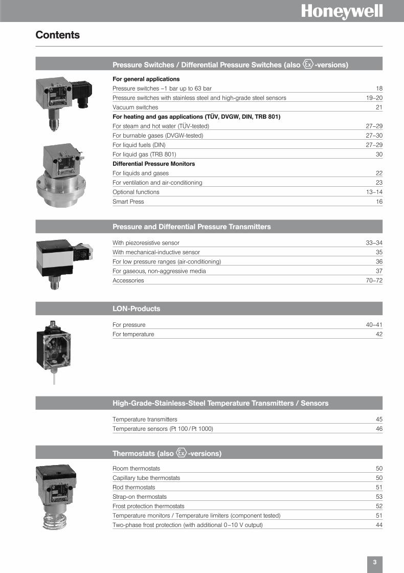
For general applications
Pressure switches –1 bar up to 63 bar 18
Pressure switches with stainless steel and high-grade steel sensors 19–20
Vacuum switches 21
For heating and gas applications (TÜV, DVGW, DIN, TRB 801)
For steam and hot water (TÜV-tested) 27–29
For burnable gases (DVGW-tested) 27–30
For liquid fuels (DIN) 27–29
For liquid gas (TRB 801) 30
Differential Pressure Monitors
For liquids and gases 22
For ventilation and air-conditioning 23
Optional functions 13–14
Smart Press 16
Temperature transmitters 45
Temperature sensors (Pt 100 / Pt 1000) 46
Contents
Pressure Switches / Differential Pressure Switches (also e -versions)
Pressure and Differential Pressure Transmitters
With piezoresistive sensor 33–34
With mechanical-inductive sensor 35
For low pressure ranges (air-conditioning) 36
For gaseous, non-aggressive media 37
Accessories 70–72
For pressure 40–41
For temperature 42
LON-Products
High-Grade-Stainless-Steel Temperature Transmitters / Sensors
Room thermostats 50
Capillary tube thermostats 50
Rod thermostats 51
Strap-on thermostats 53
Frost protection thermostats 52
Temperature monitors / Temperature limiters (component tested) 51
Two-phase frost protection (with additional 0–10 V output) 44
Thermostats (also e -versions)
01331_Product Catalog_02 19.02.2002 9:25 Uhr Seite 3

4
H
Programmable displays 70
Digital displays for transmitters 70
Safety isolating switching amplifier (for EEx-i) 71
Accessories, Pressure Mediators
Accessories for Differential Pressure Sensors
Flow Monitors
Contents
Siphons 72
NPT-adapter 72
Pressure surge reducer 72
Plugs and accessories 73
Immersion tubes 74
For liquids and gas 58–60
Solenoid Valves (also component tested, DIN, DVGW and e -versions)
Technical Information
Registration Certificates
VdTÜV, DVGW, PTB for pressure and temperature switches and solenoid valves 75
e -versions (Pressure Switch and Thermostats)
All former Ex-versions will be certified according ATEX 1000 (for gas and dust)Availability 3rd Quarter 2002
Pressure units conversion table 6
Selection criteria for pressure monitors and limiters 9
Pressure monitoring in explosion-endangered areas 10
Selection diagrams for pressure limiters and pressure monitors for steam and hot water applications 26
Equipment of a boiler with pressure monitor and pressure limiter (proposal) 26
Solenoid valves for universal applications 63
For gas, liquid gas and heating oil 64
For hot water and steam 65
Small solenoid valves 67–68
01331_Product Catalog_02 19.02.2002 9:25 Uhr Seite 4

5
HOverview of available types
Type Page
AB 67APT 70APV 70ASW… 59ASL… 60AV… 67AZ 3.1 B 14AZ 331 70AZ 3.1 B-M 62AZ 3.1 B-V 14
DCM 18DCMV 18DDCM 22DGM 30DMW 72DNM 19DNS 20DOKU 14DPS 23DPT… 37DWAM 27DWAMV 27DWR 28–29
EX 041 71EX 011 71Ex-DCM 18Ex-DDCM 22Ex-DGM 30Ex-DNM 19Ex-DNS 20Ex-DWR 28Ex-FT 52Ex-TAM 50Ex-TRM 50Ex-TX 51Ex-TXB 51Ex-VCM 21Ex-VNM 21Ex-VNS 20
FD 30FHBN… 35FHBN…355 L 41FN… 35FT, FTB 52FTS 44G 31 66G 31 GS 66
Type Page
G 35-Ex 66G 35-ExG 66GB 67GB…VA 67GK 68GS 66
H6045 / H6120 55H 1 72H 2 72H 3 72H 12 36HCD 24
K 430 / 480 72K…G 31 F 64K…G 31 M 64K…G 35 F-Ex 64K…G 35 M-Ex 64KSL 60KSW 59L…G 31 F 65L…G 31 FK 65L…G 31 M 65L…G 31 MK 65LF…20 L 42
MAU 8 72
NPT 1 72
P 17… / P 27… 46PS 16PST 16PST-R 16P2 73PZ… 45
R 1 / Ms 74R 1 / Nst 74R 10… 74R 10 / Ms 74R 10 / Nst 74R 2 / Ms 74R 2 / Nst 74R 20 / Ms 74R 20 / Nst 74R 3 / Ms 74R 4 73R 5 73R 6 74R 7 74R 8 74R 185… 46R 187… 46RN 10… 74RN 20… 74
Type Page
S6040 / S6065A 58
SDBAM 27
SK 36
SKN… 40
SKV 37
SKVN… 40
SLF… 60
SN 33–34
SN…355 L 41
ST… 73
ST 355 42
STB… 51
STW… 51
SWF… 59
T6120 54
T 69… 52
T…G 31 F 63
T…G 31 FK 65
T…G 31 M 63
T…G 31 MK 65
T…G 35 F-Ex 63
T…G 35 M-Ex 63
T…NSTF 51
TAM… 50
TRM… 50
TST 355 40
TWP… 51
TX… 51
TXB… 51
U… 72
VCM… 21
VCMV… 21
VF… 42
VKD… 71
VNM 21
VNMV 21
VNS 20
WZ 2.2 14
XIFHP 1 42
XIFLP 1 42
ZF… 13, 14
ZFM… 66
ZFT… 49
01331_Product Catalog_02 19.02.2002 9:25 Uhr Seite 5

6
Pressure SwitchOld Type New Type
DCMV 625 DWR 625-203
DNM 506 DGM 506
DNM 516 DGM 516
DNM 525 DGM 525
DNM 06 DWR 06
DNM 1 DWR 1
DNM 6 DCM 6
DNM 625 DCM 625
DNM 10 DCM 10
DNM 16 DCM 16
DNM 25 DCM 25
DNM 40 DCM 40
DNM 63 DCM 63
DNMV 025 DNS 025-203
DNMV 06 DWR 06-203
DNMV 1 DWR 1-203
DNMV 6 DCMV 6
DNMV 16 DCMV 16
DNMV 40 DCMV 40
DNMV 63 DCMV 63
Pressure SwitchOld Type New Type
Ex-DCM 025 Ex-DNS 025
Ex-DCM 06 Ex-DWR 06
Ex-DCM 1 Ex-DWR 1
Ex-DNM 506 Ex-DGM 506
Ex-DNM 516 Ex-DGM 516
Ex-DNM 525 Ex-DGM 525
Ex-DNM 06 Ex-DWR 06
Ex-DNM 1 Ex-DWR 1
Ex-DNM 3 Ex-DWR 3
Ex-DNM 6 Ex-DWR 6
Ex-DNM 625 Ex-DWR 625
Ex-DNM 16 Ex-DWR 16
Ex-DNM 25 Ex-DWR 25
Ex-DNM 40 Ex-DWR 40
Pressure TransmitterOld Type New Type
FN 5 + ED 1 SN 6-311
FN 10 + ED 1 SN 10-311
FN 25 + ED 1 SN 25-311
FN 40 + ED 1 SN 40-311
FN 5 + ED 3 SN 6-395
FN 10 + ED 3 SN 10-395
FN 25 + ED 3 SN 25-395
FN 40 + ED 3 SN 40-311
Solenoid ValveOld Type New Type
AH 10 AV102MS2
AH 13 AV131MS2
HReplacement Overview
Important notice:
All the stated pressure levels are overpressure or vacuum compared toatmospheric pressure. Overpressure is markedwith a plus sign, vacuumwith a minus sign.
Pressure units conversion table
unit bar mbar Pa kPa MPa Ib/in2 (psi)
1 bar 1 1000 105 100 0.1 14.50
1 mbar 0.001 1 100 0.1 10-4 0.0145
1 Pa 10-5 0.01 1 0.001 10-6 1.45 · 10-4
1 kPa 0.01 10 1000 1 0.001 0.145
1 MPa 10 104 106 1000 1 145
In all Fema-documents, the pressure is stated in bar, mbar or Pa.
01331_Product Catalog_02 19.02.2002 9:25 Uhr Seite 6

Pressure SwitchesAppl icat ion Guidel ine
H
01331_Product Catalog_02 19.02.2002 9:25 Uhr Seite 7

8
H
Pressure Switches for standard applications
Overpressure & Vacuum Switches in Stainless Steel
Product Overview
The Fema Pressure Switch product portfolio provides devices suitable for many applications. The portfoliocontains Special functions and equipment as well as approved devices for several kind of applications,where component-tested devices are mandatory.
All Sensors are tightness-tested with helium.
Following overview shows features and functions of Fema Pressure Switches.
Differential Pressure Monitors to control the difference between 2 measuring points. Mostly used for monitoring filter and pump function. Available types for measuring differential pressure in liquid flowsystems, as well as air flow applications.Differential Pressure Switch types available up to 16 bar.
For Pressure monitoring and pressure controlling (ON/OFF controller). Pressure range from vacuum up to63 bar overpressure. Series DCM…/DNM…/VCM…Variants and types: Screw terminals instead of plug enhanced IP Protection Ex-versions available plastic-coated housing for aggressive environment 2-step switch different switching elements
All medium contacted parts made of Stainless Steel 1.4571.Variants & types according to above sections are possible.Pressure range from vacuum up to 16 bar.
Pressure Monitor and Pressure Limited
for Steam, Hot Water, Fuel gases, Liquid gases and Fuel Oilwith all necessary component tests according to TÜV, DVGW, DIN.Pressure range up to 40 bar.Type series DA; DWR…/DGM…
Pressure Limiter featuring Safety Technology
Differential Pressure Monitors
Wherever there is a demand for high safety level monitoring supply line breaks and short circuits. together with Ex 041 Switching amplifier for EEx-i-applications suitable With plastic-coated housing suitable for chemical applications Pressure range up to 40 bar, type series DBS…Variants and types self-monitoring sensor gold contacts for EEx-i versions constrained-opened microswitch
01331_Product Catalog_02 19.02.2002 9:25 Uhr Seite 8
9
H
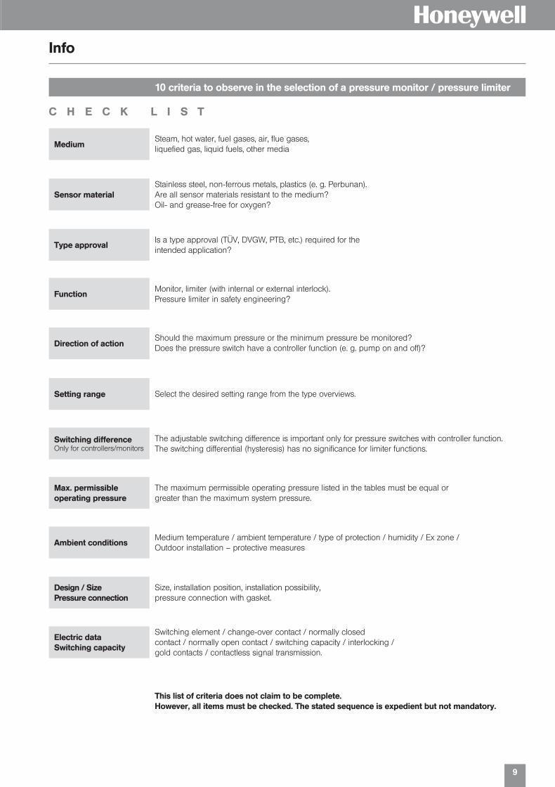
10 criteria to observe in the selection of a pressure monitor / pressure limiter
Info
Steam, hot water, fuel gases, air, flue gases,liquefied gas, liquid fuels, other media
Stainless steel, non-ferrous metals, plastics (e. g. Perbunan).Are all sensor materials resistant to the medium?Oil- and grease-free for oxygen?
Is a type approval (TÜV, DVGW, PTB, etc.) required for theintended application?
Monitor, limiter (with internal or external interlock).Pressure limiter in safety engineering?
Should the maximum pressure or the minimum pressure be monitored? Does the pressure switch have a controller function (e. g. pump on and off)?
Select the desired setting range from the type overviews.
The adjustable switching difference is important only for pressure switches with controller function. The switching differential (hysteresis) has no significance for limiter functions.
The maximum permissible operating pressure listed in the tables must be equal or greater than the maximum system pressure.
Medium temperature / ambient temperature / type of protection / humidity / Ex zone / Outdoor installation – protective measures
Size, installation position, installation possibility, pressure connection with gasket.
Switching element / change-over contact / normally closedcontact / normally open contact / switching capacity / interlocking /gold contacts / contactless signal transmission.
Medium
Sensor material
Type approval
Function
Direction of action
Setting range
Switching differenceOnly for controllers/monitors
Max. permissibleoperating pressure
Ambient conditions
Design / SizePressure connection
Electric dataSwitching capacity
C H E C K L I S T
This list of criteria does not claim to be complete. However, all items must be checked. The stated sequence is expedient but not mandatory.
01331_Product Catalog_02 19.02.2002 9:25 Uhr Seite 9

10
H
Pressure monitoring in explosion-endangered areas
Info
Pressure switches with special equipment can also be used in the Ex area Zone 1 and 2.The following alternatives are possible:
1. Pressure switch with pressure-proof encapsulated switchingdevice, degree of protection EEx de IIC T6
The pressure switch in pressure-proof encapsulation can be used directly in the Ex area (Zone 1 and 2).Maximum switching voltage, switching capacity, and ambient temperature must be taken into accountand the rules for the installation in the Ex area must be observed. All pressure switches can be equipped with Ex switching mechanisms. Special circuits as well as versions with adjustable switchingdifferences are not possible.
2. Pressure switches in EEx-i-version
All pressure switches in normal version can be used in the Ex area Zone 1 and 2, if they are incorpora-ted in an “intrinsically safe circuit”. In principle, the intrinsic safety is based on, that fact that the controlcircuit run in the Ex area carries only a small amount of energy, which is not able to generate ignitablesparks.Isolating switching amplifiers, e. g. Type Ex 011 or Ex 041 must be tested by the PTB and approved forEx-installations. Isolating switching amplifiers must in any event be installed outside the Ex zone.Pressure switches which are intended for EEx-ia installations can be equipped with blue terminals andcable entries. Because of the low voltages and currents which are carried by the contacts of the microswitch, gold plated contacts are recommended (optional function ZF 513).
3. Pressure switches with microswitch and series resistor for wire breakage and short circuit monitoring
A combination of pressure switch with mechanical microswitch connected with a 1.5 k series resistorand a 10 k parallel resistor and an isolating switching amplifier in safety technology (Type Ex 041) canalso be used for Ex zone 1 and 2 (degree of protection EEx-ia). The isolating switching amplifier insafety technology generates an intrinsically safe control circuit and simultaneously monitors the supplyline between the isolating switching amplifier and pressure switch for short circuit and line break. Please refer to the chapter on pressure switches in safety technology and data sheet Ex 041.
Ex-D…
Flameproof enclosed
Ignition protection type: EEx de IIC T6
PTB approval for the complete switchgear
Switching capacity at 230 V / 3 A.
The pressure switch can be installed inside the Ex zone.
ATEX-approval for gas anddust in preparation.
D…-513 + Ex 011
Intrinsically safe
Ignition protection type: EEx-ia
PTB approval for isolation switching amplifiers Ex 011.
Pressure switches with gold- plated contacts, blue terminals and blue cable entries.
The isolation switching amplifier must be installed outside the Ex zone.
DWAM…-576 + Ex 041
Instrinsically safe, line breakand short circuit monitoringIgnition protection type:EEx-ia
PTB approval for isolationswitching amplifiers Ex 041.
Pressure switches with safetysensor, forced opening micro-switch, gold-plated contactsblue terminals and bluecable entries.
The isolation switchingamplifier must be installedoutside the Ex zone.
Pressure monitoring in Ex areas Zone 1 and 2
max. 250 VAC, max. 3(2) A
approx. 8 VDC, max. 8 mA
Ex-Zone
Ex-Zone
approx. 8 VDC, max. 8 mA
Ex-Zone
01331_Product Catalog_02 19.02.2002 9:25 Uhr Seite 10
11
H
Switch housings for pressure switches
Component tests
Info
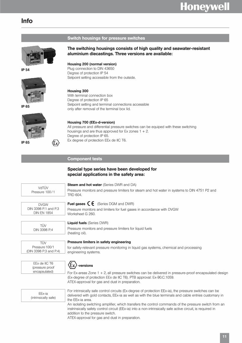
Special type series have been developed forspecial applications in the safety area:
Steam and hot water (Series DWR and DA)
Pressure monitors and pressure limiters for steam and hot water in systems to DIN 4751 P2 and TRD 604.
Fuel gases (Series DGM and DWR)
Pressure monitors and limiters for fuel gases in accordance with DVGWWorksheet G 260.
Liquid fuels (Series DWR)
Pressure monitors and pressure limiters for liquid fuels (heating oil).
Pressure limiters in safety engineering
for safety-relevant pressure monitoring in liquid gas systems, chemical and processingengineering systems.
-versions
For Ex-areas Zone 1 + 2, all pressure switches can be delivered in pressure-proof encapsulated design (Ex-degree of protection EEx de IIC T6). PTB approval: Ex-90.C.1059.ATEX-approval for gas and dust in preparation.
For intrinsically safe control circuits (Ex-degree of protection EEx-ia), the pressure switches can be delivered with gold contacts, EEx-ia as well as with the blue terminals and cable entries customary inthe EEx-ia area.An isolating switching amplifier, which transfers the control commands of the pressure switch from an instrinsically safety control circuit (EEx-ia) into a non-intrinsically safe active circuit, is required in addition to the pressure switch.ATEX-approval for gas and dust in preparation.
The switching housings consists of high quality and seawater-resistantaluminium diecastings. Three versions are available:
Housing 200 (normal version)Plug connection to DIN 43650Degree of protection IP 54Setpoint setting accessible from the outside.
Housing 300With terminal connection boxDegree of protection IP 65Setpoint setting and terminal connections accessible only after removal of the terminal box lid.
Housing 700 (EEx-d-version)All pressure and differential pressure switches can be equiped with these switchinghousings and are thus approved for Ex zones 1 + 2.Degree of protection IP 65. Ex degree of protection EEx de IIC T6.
IP 54
IP 65
IP 65
VdTÜVPressure 100 / 1
DVGWDIN 3398 P.1 and P.3
DIN EN 1854
TÜVDIN 3398 P.4
TÜVPressure 100/1
(DIN 3398 P.3 and P.4)
EEx de IIC T6(pressure proof encapsulated)
EEx-ia(intrinsically safe)
01331_Product Catalog_02 19.02.2002 9:25 Uhr Seite 11

12
HTechnical overview pressure switches
Valid for all pressure switch with microswitches of the DCM, VCM, DNM, DNS, DDC series. The technical dataof the component tested units deviate in part slightly. (Please refer to type sheet)
All pressure switches can operate under vacuum, the device is not damaged by this.
< 1 % of the working range (for pressure ranges > 1 bar)
Up to 4 g no noteworthy deviations.
With sinusoidal pressure application and room temperature, 10 x 106 switching cycles. The expected life timedepends strongly upon the type of pressure application, therefore this figure can serve only as rough estimate.With pulsating pressure or pressure impacts in hydraulic systems, pressure surge reduction is recommended.
Overvoltage category III, contamination class 3, reference surge voltage 4000 V. The conformity to DIN VDE 0110 (01.89) will be confirmed.
The parts of all pressure switches in contact with the medium are oil and grease-free (with the exception ofseries HCD… und DPS…). The sensors are hermetically encapsulated, they contain no seals (see also additional function ZF 1979, specialpacking).
Higher medium temperatures are possible if the above limit values at the switching mechanism are ensured bysuitable measures (e. g. siphon).
Vacuum
Repetition accuracy of the switching points
Vibration strength
Mechanical life
Isolation values
Oil and grease-free
Aluminium diecast GD AI Si 12G| external thread (pressure gauge connection)and G[ internal thread. Internal thread G[ at differential pressureswitches DDCM.
Floating change-over contact.With rising pressure switching over single-pole from 3–1 to 3–2
8 A at 250 VAC5 A at 250 VAC inductive8 A at 24 VDC0.3 A at 250 VDC
arbitrary, preferably vertical (see data sheet)
IP 54, Terminal connection IP 65
–
–
200 series: Plug connection 300 series: Terminal connection
Pg 11
M 16 x 1,5
-25 to +70 °C. (with the exception of DA-series –20…+70 °C andDCM 4016, 4025, 1000, VCM 4156)
Adjustable on the spindle. In switching mechanism300, the terminal box lid must be removed.
Adjustable or not adjustable(see type overview)
Max. 70 °C, briefly 85 °C
Aluminium diecast GD AI Si 12G| external thread (pressure gauge connection)and G[ internal thread. Internal thread G[ at differential pressureswitches DDCM.
Floating change-over contact.With rising pressure switching over single-pole from 3–1 to 3–2
3 A at 250 VAC2 A at 250 VAC inductive3 A at 24 VDC0.03 A at 250 VDC
vertical
IP 65
EEx de IIC T6 tested according toEN 50014 / 50018 / 50019 (CENELEC)
Ex-90.C.1059
Terminal connection
M 16 x 1,5
-15 to +60 °C
Adjustable on the spindle after theterminal box lid is removed.
Not adjustable
Max. 60 °C
Switching devicePressure connection
Switching function and connection drawing (applies only for versionwith microswitch)
Switching capacity(applies only for versionwith microswitch)
Fitting position
Degree of protection(in vertical position)
Ex degree of protection
PTB approval
Electrical connection
Cable entry plug
Cable entry terminalconnection
Ambient temperature
Switching point
Switching difference
Medium temperature
Normal versionPlug connection Terminal connection
-version
…200 …300 …700
ATEX-approval for gas and dustin preparation.
01331_Product Catalog_02 19.02.2002 9:25 Uhr Seite 12

13
Plug connection Terminal connection Connection diagrams ExplanationSeries 200 (IP 54) Series 300 (IP 65)
Normal version (plug connection)microswitch, single pole switching over, switching differential not adjustable.
Terminal connection …301housing (Series 300)
Adjustment of switching …V or see following difference …203 pages
Maximum limiter …205 see with reclosing lock-out. DWR-seriesInterlocking with increasing pressure. 29see DWR-series
Minimum limiter …206 see with reclosing lock-out. DWR-seriesInterlocking with falling pressure. 29see DWR-series
Two microswitches, switching in parallel …307or in succession. Fixed switching interval. Terminal connection case.Please state circuit diagram. (not possible on every pressure switch)
Two microswitches, 1 plug …217switching in succession, adjustable switching interval.Please state circuit diagram.(not possible on every pressure switch)
Gold-plated contacts …213Single pole switching over. Cannot be supplied with adjustable switching difference.
HOptional function ZF
Optional function / connection diagrams
Pressure Switches and Pressure Monitors
Switching capacity:max. 24 VDC,100 mA min. 5 VDC, 2 mA
Example:DCM 6 – 205
Code of switching unit (e. g. maximum limiter)Code of pressure range Sensor system
Description Plug connection Terminal connection Connection diagramsSeries 200 (IP 54) Series 300 (IP 65)
Plug connector with position indication ST 21812 V–240 VAC / DC
Protection type IP 65 and switching housing …351with surface protection (Chemical version)
Switching units / optional functions / Adjustment / Documents
Ordering text:Pressure switchDCM 6 – 205 or DCM 6 with ZF 205
01331_Product Catalog_02 19.02.2002 9:25 Uhr Seite 13

14
H
Pressure Switches and Pressure Monitors
Optional function ZF
Optional function in EEx-i equipment Type Connection diagram Isolating switchingamplifier
Gold-plated contacts, single-pole switch-over. …513 EX 011Switching differential permanent (not adjustable).Switching capacity:max. 24 VDC, 100 mA, min. 5 VDC, 2 mA
Normally closed contact with resistance combination, …576for maximum pressure monitoring. EX 041Gold-plated contacts. Housing with surface protection. (Chemical version)
Normally closed contact with reclosing lock-out and …577 EX 041resistance combination, for maximum pressure monitoring. Housing with surface protection. (Chemical version)
Normally closed contact with resistant combination …574 EX 041for minimum pressure monitoring. Gold-plated contacts.Housing with surface protection. (Chemical version)
Normally closed contact with reclosing lock-out and …575 EX 041resistance combination, for minimum pressure monitoring. Housing with surface protection. (Chemical version)
Optional function for EEx-i equipment ZF 5… Housing (300) with terminal connection (IP 65), blue cable entry and blue terminals. Partially with resistance combination for line breakage and short circuit monitoring
(with isolating switching amplifier Ex 041).
Important:All pressure switches with the optional functions listed here can be operated only together with asuitable isolating switch amplifier.
Additional optional functions Plug connection Terminal connectionReihe 200 Reihe 300
Adjustment according to customer’s instruction:one switching point …1970* …1970*two switching points or defined switching differential …1972* …1972*
Adjustment and sealing according to customer’s instruction:one switching point …1971* –two switching points or defined switching differential …1973* –Certification for Helium tightening test …1977 …1977Label of units according to customer’s instruction …1978 …1978Special packing for oil and grease-free storage …1979 …1979
Documents: additional documents, e. g. data sheets, mounting DOKU DOKUinstructions, TÜV-, DVGW- or PTB-certificate.
Certificates according to EN 10 204 Test report 2.2, type series certificate WZ 2.2 WZ 2.2
AZ 3.1 B Inspection certificate, specific product test AZ 3.1 B AZ 3.1 B
Inspection certificate for separating membranes FV AZ 3.1 B–V AZ 3.1 B–V
* Switching point adjustment: please specify switching point and direction of action (rising or falling pressure).
01331_Product Catalog_02 19.02.2002 9:26 Uhr Seite 14
H
Pressure Switchesfor Standard Applications
01331_Product Catalog_02 19.02.2002 9:26 Uhr Seite 15

16
Smart Press – new electronic pressure Switches
H
Electronic Pressure Switch PS, PST, PST…-R series
All types available in PS, PST and PST…-R version according following description:
PST V
PS = Pressure SwitchPST = Pressure Switch +
TransmitterPST…-R = Pressure Switch +
Transmitter + Relais
V = Vacuum version R = Relative pressure sensor versionA = Absolute pressure sensor version
-R = switching channel 1galvanically separatedin relay version
G12S = G ||HHHH Standard manometer versionG34F = G HHHH quasi-Flush version
01 = -1…+1 bar002 = 0–1.6 bar004 = 0–4 bar010 = 0–10 bar025 = 0–25 bar
060 = 0–60 bar100 = 0–100 bar250 = 0–250 bar600 = 0–600 bar
Accessories Smart Press
Connectors for plug 1 + 2 (OC and analog outputs):ST 12-5-G 5-prong M12 plug connector, straight versionST 12-5-A 5-prong M12 plug connector, angled version
Connectors for plug 3 (Relay output):ST 12-4-G 4-prong M12 plug connector, straight versionST 12-4-A 4-prong M12 plug connector, angled version ST 12-4-GK 4-prong M12 plug connector, straight version with 2 m cableST 12-4-AK 4-prong M12 plug connector, angled version with 2 m cable
Plug protection cap:STA 12 IP 65
01 R G34F -R
Pressure Max. all. Smart Press with range pressure 2 open collector in bar (bar) outputs
–1…+1 6 PSV01RG12S0 – 1.6 6 PS002RG12S0 – 4 12 PS004RG12S0 – 10 30 PS010RG12S0 – 25 75 PS025RG12S0 – 60 180 PS060RG12S0 – 100 300 PS100RG12S0 – 250 500 PS250RG12S0 – 600 1000 PS600RG12S
–1…+1 6 PSV01RG34F0 – 1.6 6 PS002RG34F0 – 4 12 PS004RG34F0 – 10 30 PS010RG34F0 – 25 75 PS025RG34F
0 – 2 6 PS002AG12S0 – 10 30 PS010AG12S
0 – 2 6 PS002AG34F0 – 10 30 PS010AG34F
Smart Press with 2 opencollector outputs +analog output
PSTV01RG12SPST002RG12SPST004RG12SPST010RG12SPST025RG12SPST060RG12SPST100RG12SPST250RG12SPST600RG12S
PSTV01RG34FPST002RG34FPST004RG34FPST010RG34FPST025RG34F
PST002AG12SPST010AG12S
PST002AG34FPST010AG34F
Smart Press with 2 open Pressurecollector outputs + analog rangeoutput + relay output (bar)
PSTV01RG12S-R –1…+1PST002RG12S-R 0…1.6PST004RG12S-R 0…4PST010RG12S-R 0…10PST025RG12S-R 0…25PST060RG12S-R 0…60PST100RG12S-R 0…100PST250RG12S-R 0…250PST600RG12S-R 0…600
PSTV01RG34F-R –1…+1PST002RG34F-R 0…1.6PST004RG34F-R 0…4PST010RG34F-R 0…10PST025RG34F-R 0…25
PST002AG12S-R 0…2PST010AG12S-R 0…10
PST002AG34F-R 0…2PST010AG34F-R 0…10
Type overview
01331_Product Catalog_02 19.02.2002 9:26 Uhr Seite 16

17
HType series PS…, PST…, PST…-R
Product data
ApplicationHoneywell Fema’s PS, PST and PST…-R series Electronic Pressure Switches require adjustment(configuration and parameterization) in only two modes (the basic mode and the expert mode) and aresuitable for an extremely wide range of applications, including the precision-adjustment and monitoringof system pressures in the field of plant construction, fluidics, process technology, and pneumatics, aswell as in the monitoring and control of pumps and compressors.Those versions equipped for self-monitoring are suitable for use in manufacturing lines in theautomotive industry as well as in the area of machine tool construction. These switches providesufficient accuracy (0.5 % of final value) for measurement monitoring in many laboratory applications.
Technical dataHousing and back: polybutylene terephtalate (PBT)Max. ambient temp.: –20…+60 °CStorage temperature: –35…+80 °CTemperature, medium: –20…+100 °CRelative air humidity: 0…95 %, non-condensingAccuracy, total: 0.5 % of final valueTotal weight: 380 grams
Parts in contact with mediumHigh-pressure versions 1.4571 + 1.4542Low-pressure / flush 1.4571 + 1.4435
Process connectionManometer connection G|HH external threadFlush connection GHH external thread
Electrical connectionPS and PST versions 5-prong M12 plug, A-coded as per DIN IEC 60947-5-2PST…-R version Extra 3-prong M 12 plugProtection class II as per EN 60529Climate class C as per DIN IEC 60654Power supply 14…36 VDC, max. 100 mAEMC compatible as per EN 61326/A1
Switch outputs (all versions)Open-Collector outputs Two, high/low-side, configurable, max. 250 mA / 14…36 VDCReaction time 30 msSwitching difference (SP and RP) configurable
Relay outputs (PST…-R series)Contact type 1 switch-over contactMin. electrical lifetime 250,000 switching cycles
Switching performance, gold contacts (AgSn02+Au)AC1 (resistive) 1.5 VA (24 VDC / 60 mA, 230 VAC / 6.5 mA)AC15 (inductive) unsuitable)Max. switch-on current 60 mA for < 5 msMin. switching perf. 50 mW (either > 5 V or > 2 mA)
Switching performance, silver contacts (AgSn02)AC1 (resistive) 690 VA (230 VAC / 3 A)AC15 (inductive) 230 VA (230 VAC / 1 A)Max. switch-on current 30 A for < 5 msMin. switching perf. 500 mW (> 12 V or > 10 mA)
Diagnostic outputOutput configuration warning output (plug 2), max. 20 mA, 14…36 VDC
Transmitter output (analog output)Voltage / current 0…10 V and 4…20 mA, configurable in expert modeTransient response approx. 300 ms
01331_Product Catalog_02 19.02.2002 9:26 Uhr Seite 17

H
18
Pressure switches for monitoring and control
Type series DCM
Range of Switching Max. Materials* Typeadjustment difference allowable
(Mean value) pressure
Switching difference not adjustable
1 – 16 mbar 2 mbar 1 bar NBR DCM 40164 – 25 mbar 2 mbar 1 bar + 1.4301 DCM 4025
10 – 100 mbar 12 mbar 10 bar NBR + Ms DCM 10000.04 – 0.25 bar 0.03 bar 6 bar Cu + Ms DCM 0250.1 – 0.6 bar 0.04 bar 6 bar Cu + Ms DCM 060.2 – 1.6 bar 0.04 bar 6 bar Cu + Ms DCM 1
0.2 – 2.5 bar 0.1 bar 16 bar DCM 30.5 – 6 bar 0.15 bar 16 bar Sensor-* DCM 60.5 – 6 bar 0.25 bar 25 bar housing DCM 6251 – 10 bar 0.3 bar 25 bar 1.4104 DCM 103 – 16 bar 0.5 bar 25 bar Pressure DCM 164 – 25 bar 1.0 bar 60 bar bellow DCM 258 – 40 bar 1.3 bar 60 bar 1.4571 DCM 40
16 – 63 bar 2.0 bar 130 bar DCM 63
* Stainless steel 1.4104 ≈ AISI 430 F. High grade stainless steel 1.4571 ≈ AISI 316 Ti.DCM 1000: NBR membrane + Brass (sensor housing)Cu + Ms: Copper (bellow) + Brass (sensor housing)NBR: Buna rubber
Switching difference not adjustable
1 – 16 mbar 2 mbar 1 bar NBR Ex-DCM 40164 – 25 mbar 2 mbar 1 bar NBR Ex-DCM 4025
Further pressure ranges in Ex-series see following pages.
DCM 025
DCM 25
DCM 4016
-version · Degree of protection EEx de IIC T6
for non-aggressive liquid and gaseous media
Switching difference adjustable
0.04 – 0.25 bar 0.03 – 0.4 bar 6 bar Cu + Ms DCMV 0250.1 – 0.6 bar 0.04 – 0.5 bar 6 bar Cu + Ms DCMV 060.2 – 1.6 bar 0.07 – 0.55 bar 6 bar Cu + Ms DCMV 1
0.2 – 2.5 bar 0.15 – 1.5 bar 16 bar Sensor- DCMV 30.5 – 6 bar 0.25 – 2.0 bar 16 bar housing DCMV 61 – 10 bar 0.5 – 2.8 bar 25 bar 1.4104 DCMV 103 – 16 bar 0.7 – 3.5 bar 25 bar Pressure DCMV 164 – 25 bar 1.3 – 6.0 bar 60 bar bellow DCMV 258 – 40 bar 2.6 – 6.6 bar 60 bar 1.4571 DCMV 40
16 – 63 bar 3.0 – 10 bar 130 bar DCMV 63
Cu + Ms = Copper (bellow) + Brass (sensor housing)
Range of Switching Max. Materials* Typeadjustment difference allowable
(Mean value) pressure
01331_Product Catalog_02 19.02.2002 9:26 Uhr Seite 18

H
19
Type series DNM
All parts of the DNM series of Fema pressure switches which come into contact with the medium aremade of stainless steel. The pressure sensor is welded without added material.
Range of Switching Max. Materials Typeadjustment difference allowable
(Mean value) pressure
Switching difference not adjustable
1 – 10 bar 0.15 bar 16 bar 1.4104 + Ex-DNM 1016 – 63 bar 1.0 bar 130 bar 1.4571 Ex-DNM 63
-version · Degree of protection EEx de IIC T6
DNM 025
Ex-DNM 10
Range of Switching Max. Materials Typeadjustment difference allowable
(Mean value) pressure
Switching difference not adjustable
0.04 – 0.25 bar 0.03 bar 6 bar 1.4104 + DNM 0251.4571
Pressure switches with sensor system in stainless steel version
Application
Fema pressure switches to control a minimum pressure value by switching on/off a supply pump.Level control in a cooling system.
01331_Product Catalog_02 19.02.2002 9:26 Uhr Seite 19

20
H
Pressure and vacuum switches
Type series DNS/VNS
Switching difference adjustable
-250/+100 mbar 70 –300 mbar 3 bar VNS 301–203-1*/+0.1 bar 90 –550 mbar 6 bar VNS 111–203
0.04 – 0.25 bar 60 –300 mbar 6 bar DNS 025–2030.1 – 0.6 bar 80 –400 mbar 6 bar DNS 06–2030.2 – 1.6 bar 100 –600 mbar 6 bar DNS 1–2030.2 – 2.5 bar 0.15– 1.5 bar 16 bar DNS 3–2030.5 – 6 bar 0.25– 2.0 bar 16 bar DNS 6–2031 – 10 bar 0.45– 2.5 bar 16 bar DNS 10–2033 – 16 bar 0.8 – 3.5 bar 25 bar DNS 16–203
Range of adjustment Switching diff. Max. allowable Type(Mean value) pressure
Switching difference not adjustable
-250/+100 mbar 45 mbar 3 bar VNS 301–201-1*/+0.1 bar 50 mbar 6 bar VNS 111–201
0.04 – 0.25 bar 30 mbar 6 bar DNS 025–2010.1 – 0.6 bar 40 mbar 6 bar DNS 06–2010.2 – 1.6 bar 60 mbar 6 bar DNS 1–2010.2 – 2.5 bar 0.1 bar 16 bar DNS 3–2010.5 – 6 bar 0.15 bar 16 bar DNS 6–2011 – 10 bar 0.3 bar 16 bar DNS 10–2013 – 16 bar 0.5 bar 25 bar DNS 16–201
Switching difference not adjustable
-250/+100 mbar 45 mbar 3 bar VNS 301–351-1*/+0.1 bar 50 mbar 6 bar VNS 111–351
0.04 – 0.25 bar 30 mbar 6 bar DNS 025–3510.1 – 0.6 bar 40 mbar 6 bar DNS 06–3510.2 – 1.6 bar 60 mbar 6 bar DNS 1–3510.2 – 2.5 bar 0.1 bar 16 bar DNS 3–3510.5 – 6 bar 0.15 bar 16 bar DNS 6–3511 – 10 bar 0.3 bar 16 bar DNS 10–3513 – 16 bar 0.5 bar 25 bar DNS 16–351
Switching difference not adjustable
-250/+100 mbar 45 mbar 3 bar Ex-VNS 301-1*/+0.1 bar 50 mbar 6 bar Ex-VNS 111
0.04 – 0.25 bar 30 mbar 6 bar Ex-DNS 0250.1 – 0.6 bar 40 mbar 6 bar Ex-DNS 060.2 – 1.6 bar 60 mbar 6 bar Ex-DNS 10.2 – 2.5 bar 0.1 bar 16 bar Ex-DNS 30.5 – 6 bar 0.15 bar 16 bar Ex-DNS 61 – 10 bar 0.3 bar 16 bar Ex-DNS 103 – 16 bar 0.5 bar 25 bar Ex-DNS 16
DNS 1-201
DNS 1-351
Ex-DNS 3
Chemical version (housing with surface protection)
Housing with high-grade stainless steel system (1.4571). Degree of protection IP 65.
with high-grade stainless steel sensor system 1.4571All sensor parts connected to the media are made of stainless steel 1.4571.
-version · Degree of protection EEx de IIC T6
* In the case of very highvacuum, close to the negativepressure of -1bar which isonly theoretically possible, theswitch can be adjusted onlywith reservations on accountof the special conditions ofvacuum technology. Thepressure switch itself willhowever not be damaged atmaximum negative pressure.
Range of adjustment Switching diff. Max. allowable Type(Mean value) pressure
Range of adjustment Switching diff. Max. allowable Type(Mean value) pressure
01331_Product Catalog_02 19.02.2002 9:26 Uhr Seite 20

21
HType series VCM
The Fema Negative Pressure Switches detect the pressure difference relative to the atmospheric pres-sure. All data on switching pressure ranges and therefore also the scale divisions on the switch units areto be understood as the difference in pressure between the atmospheric pressure at any one time andthe set switching pressure. The “zero” reference point on the scale of the unit corresponds to the atmos-pheric pressure at the time.
Switching difference not adjustable
-15 / + 6 mbar 2 mbar 1 bar Perbunan VCM 4156-250 / + 100 mbar 25 mbar 1.5 bar Cu + Ms VCM 301
-1*/ + 0.1 bar 45 mbar 3 bar Cu + Ms VCM 101-0.9/ + 0.5 bar 50 mbar 3 bar Cu + Ms VCM 095
-250 / + 100 mbar 45 mbar 3 bar 1.4104 VNM 301-1*/ + 0.1 bar 50 mbar 6 bar 1.4104 VNM 111
Switching difference adjustable
-250 / + 100 mbar 30 – 200 mbar 1.5 bar Cu + Ms VCMV 301-1*/ + 0.1 bar 80 – 350 mbar 3 bar Cu + Ms VCMV 101-0.9/ + 0.5 bar 90 – 400 mbar 3 bar Cu + Ms VCMV 095
-250 / + 100 mbar 70 – 450 mbar 3 bar 1.4104 VNMV 301-1*/ + 0.1 bar 90 – 650 mbar 6 bar 1.4104 VNMV 111
* Stainless steel 1.4104 ≈ AISI 430 F. High grade stainless steel 1.4571 ≈ AISI 316 Ti.DCM 1000: NBR membrane + Brass (sensor housing)Cu + Ms: Copper (bellow) + Brass (sensor housing)NBR: Buna rubber
VCM 301
VNM 111
Switching difference not adjustable
-15 / + 6 mbar 2 mbar 1 bar Perbunan Ex-VCM 4156-250 / + 100 mbar 25 mbar 1.5 bar Cu + Ms Ex-VCM 301-250 / + 100 mbar 45 mbar 3 bar 1.4104 Ex-VNM 301
-1*/ + 0.1 bar 45 mbar 3 bar Cu + Ms Ex-VCM 101-0.9/ + 0.5 bar 50 mbar 3 bar Cu + Ms Ex-VCM 095-1*/ + 0.1 bar 50 mbar 6 bar 1.4104 Ex-VNM 111
-250 / + 100 mbar 45 mbar 3 bar 1.4571 Ex-VNS 301-1*/ + 0.1 bar 50 mbar 6 bar 1.4571 Ex-VNS 111
-version · Degree of protection EEx de IIC T6
*In the case of very high vacuum, close to the negative pressure of –1 bar which is only theoreticallypossible, the switch can be adjusted only with reservations on account of the special conditions ofvacuum technology. The pressure switch itself will however not be damaged at maximum negativepressure.
Negative Pressure Switches (Vacuum Switch)
Range of Switching Max. Materials* Typeadjustment difference allowable
(Mean value) pressure
Range of Switching Max. Materials* Typeadjustment difference allowable
(Mean value) pressure
01331_Product Catalog_02 19.02.2002 9:26 Uhr Seite 21

22
Pump monitoring, filter monitoring, flow monitoring
The differential Pressure of a pump ismonitored by a DDCM… Pressure Switch.
When pressure falls below a certainadjusted level, the switch will be activated.The DDCM-Differential Pressure Switchacts independent of the static pressure ofthe application.
Independent static pressure conditions in the system. See also chapter “Differential Pressure Trans-mitter” for same applications.
H
Differential Pressure Switches
Type series DDC
for liquid and gaseous media (e. g. for hot/cold water, steam and gas)The Fema differential pressure switches are suitable for monitoring differential pressures, flow monitoring and automatic checking of filter plants. A double chamber system with stainless steel bellows resp. perbunan diaphragm accurately detects the difference between the two applied pressures.The differential pressure to be monitored is adjustable within the ranges mentioned in the summary oftypes. The DDCM differential pressure switches can also be used in vaccum.The switching difference is not adjustable.
Range of adjustment Switching diff. Max.** Material Type(differential pressure) (Mean value) allowable
pressure
4 – 25 mbar 2 mbar 0.5 bar DDCM 252*10 – 60 mbar 15 mbar 1.5 bar Aluminium DDCM 662*20 – 160 mbar 20 mbar 3 bar + Perbunan DDCM 1602*
100 – 600 mbar 35 mbar 3 bar DDCM 6002*
–0.1 – 0.4 bar 0.15 bar 15 bar DDCM 014*0.2 – 1.6 bar 0.13 bar 15 bar Stainless steel DDCM 11 – 4 bar 0.2 bar 25 bar 1.4305 + DDCM 4*0.5 – 6 bar 0.2 bar 15 bar 1.4571 DDCM 63 – 16 bar 0.6 bar 25 bar DDCM 16
Further differential Pressure Switches see DPS- and HCD-series.Accessories see VKD …, page 71, and MAU 8 …, page 72.
Range of adjustment Switching diff. Max.** Material Type(differential pressure) (Mean value) allowable
pressure
4 – 25 mbar 2 mbar 0.5 bar Ex-DDCM 252*10 – 60 mbar 15 mbar 1.5 bar Aluminium Ex-DDCM 662*20 – 160 mbar 20 mbar 3 bar + Perbunan Ex-DDCM 1602*
100 – 600 mbar 35 mbar 3 bar Ex-DDCM 6002*
-0.1 – 0.4 bar 0.15 bar 15 bar Ex-DDCM 014*0.2 – 1.6 bar 0.13 bar 15 bar Stainless steel Ex-DDCM 11 – 4 bar 0.2 bar 25 bar 1.4305 + Ex-DDCM 4*0.5 – 6 bar 0.2 bar 15 bar 1.4571 Ex-DDCM 63 – 16 bar 0.6 bar 25 bar Ex-DDCM 16
DDCM 252
Ex-DDCM 1
-version · Degree of protection EEx de IIC T6
ATEX-approval for gas and dust inpreparation.
Application sample
* without graduation(only ± scale)
** also load one direction
01331_Product Catalog_02 19.02.2002 9:26 Uhr Seite 22

23
H
Differential pressure switches for ventilation and air-conditioning
Type series DPS
Differential pressure switch for filter, fan or air flow monitoring in air-conditioning and ventilation systems.
Accessories supplied with the device:2 m silicone hose, 2 connection pieces with mounting screws,2 self-tapping screws for mounting the housing, 3 screw terminals for the electrical connection.
Optional accessoryDPSLF L-shaped bracket for installation turned by 90°, e. g. in the ceiling area.
(DPS 400 L includes DPS 400 together with L-shaped mounting bracket).
The housing lid can be mounted in 3 different directions. This allows max. flexibility in cable entranceand pressure connection mounting directions.
Setting range Switching difference Typefor upper switching pressure (Mean values)
20 – 200 Pa 10 Pa DPS 200 F40 – 400 Pa 20 Pa DPS 400 F
200 – 1000 Pa 100 Pa DPS 1000 F500 – 2500 Pa 150 Pa DPS 2500 F
Type overview
DPS
Pressure connection: Plastic connection piece with 6 mm external diameter.Pressure medium: Air, as well as non-combustible and non-aggressive gases.Pressure membrane: Silicon.Maximum permissible operatingpressure: 5000 Pa for all types.Switching function: single-pole change-over.Switching capacity: 1.5 (0.4) A / 250 VACType of protection: IP 54
01331_Product Catalog_02 19.02.2002 9:26 Uhr Seite 23

24
H
Pressure and Differential pressure switches for neutral gases (DVGW-tested)
Type series HCD
Range Switching diff. Max. DVGW Typeof adjustment (Pascal) working Reg.-No.
(Pascal) in in pressurelower upper (Pascal)range range
20 – 300 30 – 50 10000 E 3085/2 HCD 6003100 – 1000 30 – 100 10000 E 3085/2 HCD 6010500 – 5000 150 – 300 20000 E 3085/2 HCD 6050
1500 – 15000 400 – 1000 30000 E 3085/2 HCD 6150
The switching differential is not adjustable. The low switching differentials are valid for the lower range ofadjustment, the higher values for the upper ranges.
These Pressure Switches are only available in above mentioned versions. No additional functions andfeatures possible.
The pressure switches of series HCD are suitable for neutral and non-aggressive gases. They can beused for monitoring overpressure, vacuum and differential pressure. It complies with the gas appliancedirective 90 / 396 / EEC.
HCD
Pressure connection: Pressure connection for overpressure: G[, internal tread.For vacuum and differential pressure: G @ß(, internal thread.
Type of protection: IP 40 according to DIN 40050.
01331_Product Catalog_02 19.02.2002 9:26 Uhr Seite 24

25
Pressure Switchesfor Safety Applications
H
01331_Product Catalog_02 19.02.2002 9:26 Uhr Seite 25

26
H
Selection of the pressure monitors / pressure limiters
Equipment of a boiler with pressure monitor and pressure limiter
Info
Application sample
Selection diagrams
Minimum pressure monitors (DRW series) can alsobe used as protection against running dry forinstallations up to 350 kW.
Pressure monitor for burnercontrolDWAM… or DWR… (without adjustable switchingdifferential)or DWAMV… or DWR…–203 (with adjustable switching difference for controlling function)
Maximum / minimumpressure limiter for safetymonitoring:SDBAM… or DWR…–205(with internal interlock, unlockingbutton on the pressure limiter) orDWAM… or DWR…(with external interlock in the controlcabinet).
Application sample for externalinterlock see.
Pressure monitorDWAM… or DWR…
Pressure limiterSDBAM… orDWR…-205
for steam and hot water systems according to TRD 604, DIN 4751, P. 2
01331_Product Catalog_02 19.02.2002 9:26 Uhr Seite 26

27
H
Maximum pressure monitors and limiters
Type series DA
Type overview
Range of Switching diff. Max. operating TÜV- Typeadjustment (Mean value) pressure Registration-No.
(bar) (bar) (bar)
Pressure monitors without differential adjustment for max. pressure monitoring*
0.1 – 0.6 0.04 5 TÜV.DW.99–132 DWAM 060.2 – 1.6 0.05 5 TÜV.DW.99–132 DWAM 11.2 – 6 0.2 10 TÜV.DW.99–132 DWAM 61.2 – 6 0.25 20 TÜV.DW.99–132 DWAM 6253 – 16 0.4 20 TÜV.DW.99–132 DWAM 166 – 32 1.2 45 TÜV.DW.99–132 DWAM 32
Pressure limiters without differential adjustment for max. pressure monitoring*
0.2 – 1.6 0.12 5 TÜV.SDB.99–134 SDBAM 10.4 – 2.5 0.15 5 TÜV.SDB.99–134 SDBAM 2.51.2 – 6 0.4 10 TÜV.SDB.99–134 SDBAM 61.2 – 6 0.6 20 TÜV.SDB.99–134 SDBAM 6253 – 16 0.8 20 TÜV.SDB.99–134 SDBAM 166 – 32 3.0 45 TÜV.SDB.99–134 SDBAM 32
* The pressure monitors DWAM… can also be used for maximum pressure limitation, by using an externalinterlock.
Pressure monitors with differential adjustment for max. pressure monitoring
0.2 – 1.6 0.12– 0.6 5 TÜV.DW.99–133 DWAMV 11.2 – 6 0.4 – 1.5 10 TÜV.DW.99–133 DWAMV 63 – 16 0.8 – 2.5 20 TÜV.DW.99–133 DWAMV 166 – 32 2.5 – 6.0 45 TÜV.DW.99–133 DWAMV 32
For Minimum Pressure monitoring see series DWR… – Minimum Pressure Monitor: DWR… (also available as a Maximum Pressure Monitor).– Minimum Pressure Limiter: DWR with extension …-206
In case of Minimum Pressure Limitation the sensor bellows are from “self monitoring” construction.
DWAM 1
SDBAM 2,5
Special features “Of special construction”due to selfmonitoring
SealingGenerally available forsafety pressure limitingdevices SDBAM. Forpressure monitor switchesupon request.
Welded sensorcompletely made of stainless steel
Available in EEx-i version(see also DBS-series)
Medium and ambienttemperature –20 to +70 °C
TÜVT E S T E D
with selfmonitoring sensor for steam and hot waterComponent tested for: Steam Systems according to TRD 604
Hot water Systems according to DIN 4751, P.2
Testing basis: VdTÜV-Memorandum “Druck 100/1”
TÜV-Registration No.: TÜV · DW 99–132 for series DWAM…TÜV · DW 99–133 for series DWAMV…TÜV · SDB 99–134 for series SDBAM…
Function: Pressure monitor / Pressure limiter
Direction of action: For max. pressure monitoring
Sensor: “Of special construction” due to selfmonitoring
Range of Switching diff. Max. operating TÜV- Typeadjustment (Mean value) pressure Registr.-No.
(bar) (bar) (bar)
01331_Product Catalog_02 19.02.2002 9:26 Uhr Seite 27
28
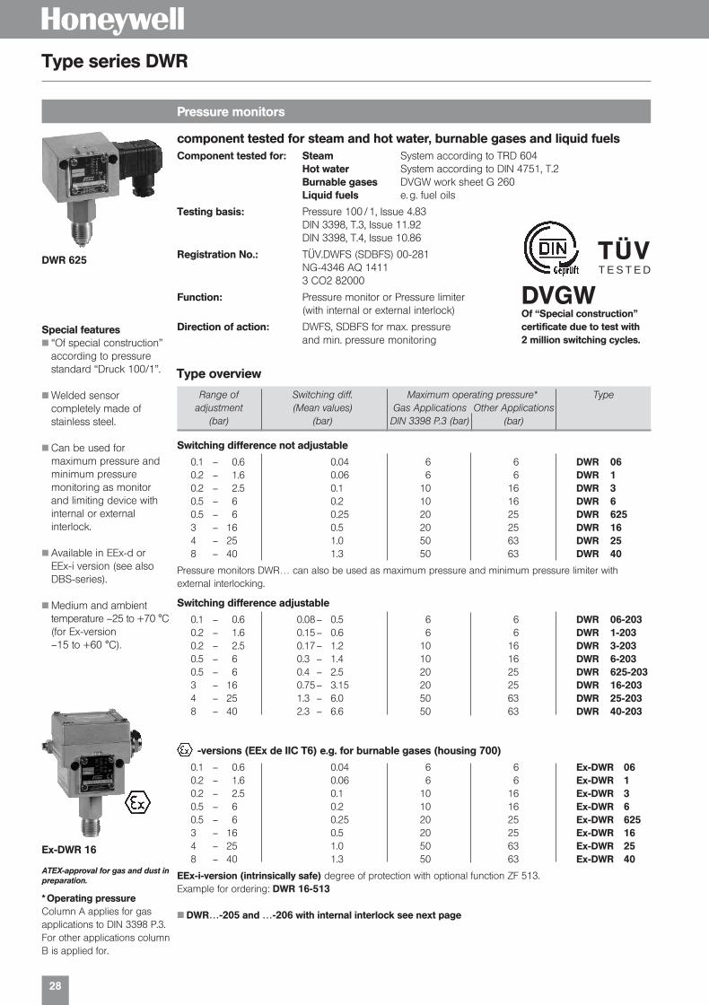
component tested for steam and hot water, burnable gases and liquid fuelsComponent tested for: Steam System according to TRD 604
Hot water System according to DIN 4751, T.2Burnable gases DVGW work sheet G 260Liquid fuels e. g. fuel oils
Testing basis: Pressure 100 / 1, Issue 4.83DIN 3398, T.3, Issue 11.92DIN 3398, T.4, Issue 10.86
Registration No.: TÜV.DWFS (SDBFS) 00-281NG-4346 AQ 14113 CO2 82000
Function: Pressure monitor or Pressure limiter (with internal or external interlock)
Direction of action: DWFS, SDBFS for max. pressure and min. pressure monitoring
H
TÜVT E S T E D
Pressure monitors
Type series DWR
DVGWOf “Special construction” certificate due to test with 2 million switching cycles.
DWR 625
Type overview
Range of Switching diff. Maximum operating pressure* Typeadjustment (Mean values) Gas Applications Other Applications
(bar) (bar) DIN 3398 P.3 (bar) (bar)
Switching difference not adjustable
0.1 – 0.6 0.04 6 6 DWR 060.2 – 1.6 0.06 6 6 DWR 10.2 – 2.5 0.1 10 16 DWR 30.5 – 6 0.2 10 16 DWR 60.5 – 6 0.25 20 25 DWR 6253 – 16 0.5 20 25 DWR 164 – 25 1.0 50 63 DWR 258 – 40 1.3 50 63 DWR 40
Pressure monitors DWR… can also be used as maximum pressure and minimum pressure limiter withexternal interlocking.
Switching difference adjustable
0.1 – 0.6 0.08– 0.5 6 6 DWR 06-2030.2 – 1.6 0.15– 0.6 6 6 DWR 1-2030.2 – 2.5 0.17– 1.2 10 16 DWR 3-2030.5 – 6 0.3 – 1.4 10 16 DWR 6-2030.5 – 6 0.4 – 2.5 20 25 DWR 625-2033 – 16 0.75– 3.15 20 25 DWR 16-2034 – 25 1.3 – 6.0 50 63 DWR 25-2038 – 40 2.3 – 6.6 50 63 DWR 40-203
-versions (EEx de IIC T6) e.g. for burnable gases (housing 700)
0.1 – 0.6 0.04 6 6 Ex-DWR 060.2 – 1.6 0.06 6 6 Ex-DWR 10.2 – 2.5 0.1 10 16 Ex-DWR 30.5 – 6 0.2 10 16 Ex-DWR 60.5 – 6 0.25 20 25 Ex-DWR 6253 – 16 0.5 20 25 Ex-DWR 164 – 25 1.0 50 63 Ex-DWR 258 – 40 1.3 50 63 Ex-DWR 40
EEx-i-version (intrinsically safe) degree of protection with optional function ZF 513.Example for ordering: DWR 16-513
DWR…-205 and …-206 with internal interlock see next page
Special features “Of special construction”
according to pressurestandard “Druck 100/1”.
Welded sensorcompletely made ofstainless steel.
Can be used formaximum pressure andminimum pressuremonitoring as monitorand limiting device withinternal or externalinterlock.
Available in EEx-d or EEx-i version (see alsoDBS-series).
Medium and ambient temperature –25 to +70 °C(for Ex-version–15 to +60 °C).
Ex-DWR 16
* Operating pressureColumn A applies for gasapplications to DIN 3398 P.3.For other applications columnB is applied for.
ATEX-approval for gas and dust inpreparation.
01331_Product Catalog_02 19.02.2002 9:26 Uhr Seite 28
29
H
Pressure limiters
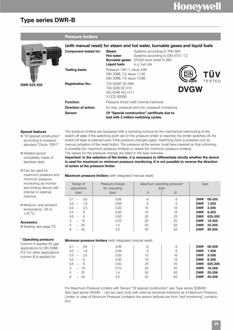
Type series DWR-B
DWR 625-205
Special features “Of special construction”
according to pressurestandard “Druck 100/1”
Welded sensorcompletely made ofstainless steel.
Can be used formaximum pressure andminimum pressuremonitoring as monitorand limiting device withinternal or externalinterlock.
Medium- and ambienttemperature –25 to+70 °C.
Accessory Sealing, see page 73.
* Operating pressureColumn A applies for gasapplications to DIN 3398,P.3. For other applicationscolumn B is applied for.
The pressure limiters are equipped with a reclosing lockout for the mechanical interlocking of theswitch-off state. If the switching point set on the pressure limiter is reached, the limiter switches off, theswitch-off state is retained even if the pressure changes again. Switching back is possible only bymanual actuation of the reset button. The pressure at the sensor must have lowered so that unlockingis possible (for maximum pressure limiters) or raised (for minimum pressure limiters).The values for the pressure change are listed in the type overview.Important: In the selection of the limiter, it is necessary to differentiate strictly whether the deviceis used for maximum or minimum pressure monitoring. It is not possible to reverse the directionof action at the pressure limiter.
Maximum pressure limiters (with integrated manual reset)
0.1 – 0.6 0.06 6 6 DWR 06-2050.2 – 1.6 0.09 6 6 DWR 1-2050.2 – 2.5 0.20 10 16 DWR 3-2050.5 – 6 0.30 10 16 DWR 6-2050.5 – 6 0.50 20 25 DWR 625-2053 – 16 0.70 20 25 DWR 16-2054 – 25 1.4 50 63 DWR 25-2058 – 40 2.3 50 63 DWR 40-205
Minimum pressure limiters (with integrated manual reset)
0.1 – 0.6 0.06 6 6 DWR 06-2060.2 – 1.6 0.09 6 6 DWR 1-2060.2 – 2.5 0.20 10 16 DWR 3-2060.5 – 6 0.30 10 16 DWR 6-2060.5 – 6 0.50 20 25 DWR 625-2063 – 16 0.70 20 25 DWR 16-2064 – 25 1.4 50 63 DWR 25-2068 – 40 2.3 50 63 DWR 40-206
For Maximum Pressure Limiters with Sensor “Of special construction” see Type series SDBAM.Also type series DWAM… can be used (only with external electrical interlock) as a Maximum PressureLimiter. In case of Minimum Pressure Limitation the sensor bellows are from “self monitoring” construc-tion.
(with manual reset) for steam and hot water, burnable gases and liquid fuelsComponent tested for: Steam Systems according to TRD 604
Hot water Systems according to DIN 4751, T.2Burnable gases DVGW work sheet G 260Liquid fuels e. g. fuel oils
Testing basis: Pressure 100 / 1, Issue 4.83DIN 3398, T.3, Issue 11.92DIN 3398, T.4, Issue 10.86
Registration No.: TÜV.SDBF 02-309TÜV.SDB 02-310NG-4346 AQ 14113 CO2 82000
Function: Pressure limiter (with internal interlock)
Direction of action: for max. pressure and min. pressure monitoring
Sensor: Of “Special construction” certificate due totest with 2 million switching cycles.
Range of Pressure change Maximum operating pressure* Typeadjustment for unlocking (bar)
(bar) (bar) A B
TÜVT E S T E D
DVGW
01331_Product Catalog_02 19.02.2002 9:26 Uhr Seite 29

30
H
Pressure Monitors for fuel gases
Type series DG
Maximum pressure limiter for liquid gas systems
Type series FD
DVGW-tested to DIN 3398, part 1 and part 3 and gas appliance directive 90/396 EECThe gas pressure monitors are suitable for all gases to the DVGW work-sheet G 260 and for air. Tested to the requirements of DIN 3398 part 1 and part 3. Ambient temperature: –25° to 60 °C. DVGW-Registration No. NG-4346 AP 1011. CE-Identnumber: CE-0085 AQ 1088.
15 – 60 mbar 6 mbar 0.8 bar Cu + Ms DGM 306 A20 – 100 mbar 7 mbar 0.8 bar Cu + Ms DGM 310 A40 – 250 mbar 10 mbar 0.8 bar Cu + Ms DGM 325 A
100 – 600 mbar 25 mbar 2 bar Cu + Ms DGM 06 A0.2 – 1.6 bar 40 mbar 3 bar Cu + Ms DGM 1 A
15 – 60 mbar 8 mbar 5 bar 1.4104 DGM 50640 – 160 mbar 12 mbar 5 bar 1.4104 DGM 516
100 – 250 mbar 20 mbar 5 bar 1.4104 DGM 525
* Stainless steel 1.4104 ≈ AISI 430 F
EExi-version (intrinsically) · Degree of protection EEx-iaAs above, but with optional function ZF 513 (EEx-i). Example for ordering: DGM 516–513
15 – 60 mbar 10 mbar 5 bar 1.4104 Ex-DGM 50640 – 160 mbar 12 mbar 5 bar 1.4104 Ex-DGM 516
100 – 250 mbar 20 mbar 5 bar 1.4104 Ex-DGM 525
Further pressure monitors for fuel gases see series DWR and HCD.
-version · Degree of protection EEx de IIC T6Ambient temperature –15° to 60 °CDVGW-Registration-No. NG-4346 AP 1011.
TÜV-tested, with manual reset interlockSetting range 3–16 barThe series FD pressure limiters are constructed in accordance with the special directives of liquid gasengineering. The requirements of TRB 801 Appendix II § 12 are fullfiled. All parts of the sensor cominginto contact with the medium are stainless steel 1.4104 and 1.4571. Over and above the requirements ofthe TRB, the pressure sensor is of self-monitoring design, i. e. in the event of rupture of the pressure bellows, the pressure limiter switches off to the safe side. The pressure sensor thus complies with“Special Design” as defined in VdTÜV Code of Practice “Pressure 100/1”. The pressure limiters are operated in intrinsically safe control circuits (Explosion-proof Protection EEx-ia). With the Ex 041 isolatingswitching amplifier, the control circuit is additionally monitored for circuit break and short-circuit.
Switching Interlock* TÜV Reg. No. Typedifferential
0.5 external 09-91-0109 FD 16-3262.5 internal 09-91-0110 FD 16-327
Important: They only may be used in conjunction with Ex 041 isolating switching amplifier.* Interlock on reaching to cutout point (maximum pressure set).
DGM 310 A
Ex-DGM 506
FD 16-326
EEx ia
ATEX-approval for gas and dust inpreparation.
Range of Switching Max. Materials* Typeadjustment differential working
(Mean value) pressure
Range of Switching Max. Materials* Typeadjustment differential working
(Mean value) pressure
01331_Product Catalog_02 19.02.2002 9:26 Uhr Seite 30

Pressure Transmitters
H
01331_Product Catalog_02 19.02.2002 9:27 Uhr Seite 31

32
H
Pressure and differential pressure transmitters
Overview MODUFLEX
Type series Ranges Medium Output Sensor Notes / applicationsignal
SN Pressure up Liquid and 0–10 V/ piezoresistive High pressure controlto 60 bar gaseous 4–20 mA Stainless steel sensorWorking ranges (stainless (3-wire- Display module optionsof SN…-395 steel system)adjustable sensors) Display AZ 331 forby jumper 3-wire-system3-wire-system
Pressure up Liquid and 4–20 mA piezoresistive Display AZG 241 forto 40 bar gaseous (2-wire- 2-wire-system2-wire-system (stainless system)
steelsensors)
F Vacuum up Liquid and 0–10 V mechanical Also with display AZ 331to 40 bar gaseous 0–20 mA inductiv Also for vacuum andDifferential pressure 4–20 mA differential pressureup to 10 bar (3-wire-Working ranges System)steplessly adjustable
SK ± 5 mbar to Gaseous 0–10 V piezoresistive For heating and air conditioning0–20 mbar e. g. for filter andWorking ranges ventilation systemsfixed or adjustableby jumper Also with LCD-display AK-SK
DPT Up to 0–25 mbar Gaseous 0–10 V piezoresistive Also with LED-display
LON products for pressure, Liquid mechanical differential pressure and inductivand temperature gaseous piezoresistive
The user friendly plugs can beopened.Apart from simplified installation,it is possible to measure the supplyvoltage and output signal directlyat the open plug.
Conditon on delivery: The transmitters areassembled completely in the factory (sensor +evaluation module + cover) and adjusted to thenominal range.Additional modules and external modules aredelivered separately.
Factory adjustment: The devices are adjustedin factory to the relevant nominal range.
01331_Product Catalog_02 19.02.2002 9:27 Uhr Seite 32
33
H
Working range Smallest settable Max. allowable Type(nominal range) working range pressure
(bar) (bar) (bar)
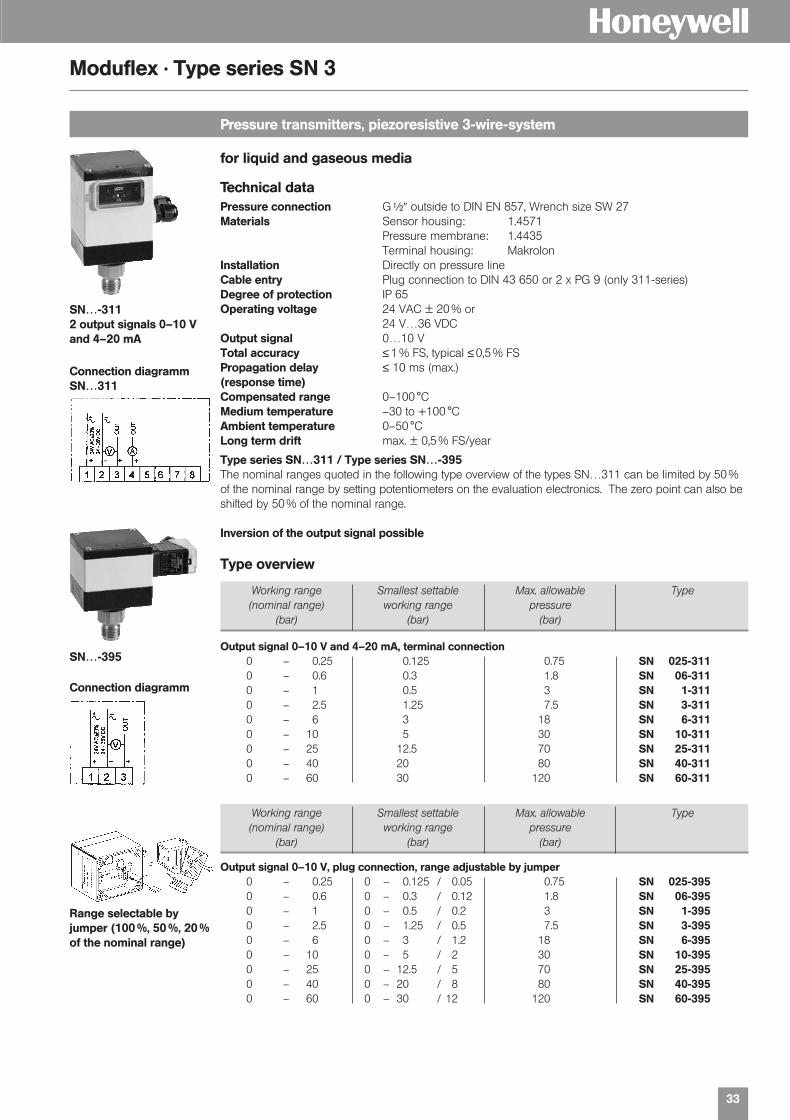
Pressure transmitters, piezoresistive 3-wire-system
Moduflex · Type series SN 3
Technical dataPressure connection G| outside to DIN EN 857, Wrench size SW 27Materials Sensor housing: 1.4571
Pressure membrane: 1.4435Terminal housing: Makrolon
Installation Directly on pressure line Cable entry Plug connection to DIN 43 650 or 2 x PG 9 (only 311-series)Degree of protection IP 65 Operating voltage 24 VAC ± 20 % or
24 V…36 VDCOutput signal 0…10 VTotal accuracy ≤ 1 % FS, typical ≤ 0,5 % FS Propagation delay ≤ 10 ms (max.)(response time)Compensated range 0–100 °CMedium temperature –30 to +100 °CAmbient temperature 0–50 °CLong term drift max. ± 0,5 % FS/year
Type series SN…311 / Type series SN…-395The nominal ranges quoted in the following type overview of the types SN…311 can be limited by 50%of the nominal range by setting potentiometers on the evaluation electronics. The zero point can also beshifted by 50% of the nominal range.
Inversion of the output signal possible
Type overview
Working range Smallest settable Max. allowable Type(nominal range) working range pressure
(bar) (bar) (bar)
Output signal 0–10 V and 4–20 mA, terminal connection0 – 0.25 0.125 0.75 SN 025-3110 – 0.6 0.3 1.8 SN 06-3110 – 1 0.5 3 SN 1-3110 – 2.5 1.25 7.5 SN 3-3110 – 6 3 18 SN 6-3110 – 10 5 30 SN 10-3110 – 25 12.5 70 SN 25-3110 – 40 20 80 SN 40-3110 – 60 30 120 SN 60-311
Output signal 0–10 V, plug connection, range adjustable by jumper0 – 0.25 0 – 0.125 / 0.05 0.75 SN 025-3950 – 0.6 0 – 0.3 / 0.12 1.8 SN 06-3950 – 1 0 – 0.5 / 0.2 3 SN 1-3950 – 2.5 0 – 1.25 / 0.5 7.5 SN 3-3950 – 6 0 – 3 / 1.2 18 SN 6-3950 – 10 0 – 5 / 2 30 SN 10-3950 – 25 0 – 12.5 / 5 70 SN 25-3950 – 40 0 – 20 / 8 80 SN 40-3950 – 60 0 – 30 / 12 120 SN 60-395
Connection diagrammSN…311
Connection diagramm
SN…-3112 output signals 0–10 Vand 4–20 mA
Range selectable byjumper (100 %, 50 %, 20 %of the nominal range)
for liquid and gaseous media
SN…-395
01331_Product Catalog_02 19.02.2002 9:27 Uhr Seite 33

34
H
Pressure transmitters for liquid and gaseous media, 2-wire-system
Moduflex · Type series SN 2
Technical dataPressure connection G| outside to DIN EN 837, Wrench size SW 27Material Terminal housing: Makrolon
Sensor housing: 1.4571Pressure membrane: 1.4435
Installation Directly on pressure lineCable entry Plug connection to DIN 43 650
PG 11Protection class IP 65Operating voltage 10 V … 30 VDCOutput signal 4…20 mA, load ≤ (UB–10 V)/0.02 ATotal accuracy ≤ 1 % FS Response time ≤ 10 msCompensated range 0…100 °CMax. medium temperature –30…+110 °CAmbient temperature 0…60 °CWork direction Increasing creating pressure: = increased output signal
Working range Max. allowable Type(bar) pressure
(bar)
Plug connection0 – 0.25 0.75 SN 025-2800 – 0.6 1.8 SN 06-2800 – 1 3 SN 1-2800 – 1.6 6.4 SN 2-2800 – 2.5 7.5 SN 3-2800 – 4 16 SN 4-2800 – 6 18 SN 6-2800 – 10 30 SN 10-2800 – 16 48 SN 16-2800 – 25 70 SN 25-2800 – 40 80 SN 40-2800 – 60 120 SN 60-280
Accessory: Programmable Display APV 630.
Type overview
LED-display adjustable for SN…–280 AZG 241to be mounted between plug and transmitter, programmable, 4 digits
Not adjustable
User friendly plug for easyinstallation and service
SN… –280
01331_Product Catalog_02 19.02.2002 9:27 Uhr Seite 34

35
H
Pressure transmitter, mechanical-inductive for liquid and gaseous media
Moduflex · Type series F + ED 3
Pressure transmitter in 3-wire-system with output signal 0–10 V and 0–20 mA output signal can be reversed LED-display AZ 331 optional
The sensor module contains the electrical connectors for power supply and output signal for all pluggedmodules, i. e. Display module AZ 331.The nominal ranges can be reduced to the below mentioned smallest settable working ranges byrecalibration.
Working range Smallest settable Max. Sensor- Type(nominal range) working range allowable material
Po–Pn (approx. values) pressure
Overpressure0 – 50 mbar 20 mbar 2.5 bar FN 505 + ED 30 – 100 mbar 25 mbar 5 bar FN 510 + ED 30 – 250 mbar 65 mbar 6 bar FN 025 + ED 30 – 500 mbar 125 mbar 6 bar Stainless FN 05 + ED 30 – 1 bar 250 mbar 6 bar steel FN 1 + ED 30 – 2.5 bar 0.7 bar 16 bar 1.4104 FN 3 + ED 30 – 6 bar 3 bar 18 bar + SN 6-311*0 – 10 bar 5 bar 30 bar 1.4571 SN 10-311*0 – 25 bar 12.5 bar 70 bar SN 25-311*0 – 40 bar 20 bar 80 bar SN 40-311*
* piezoresistive sensor
0 – 500 mbar 125 mbar 10 bar Stainless FHBN 05 + ED 30 – 1 bar 250 mbar 15 bar steel FHBN 1 + ED 30 – 2.5 bar 0.7 bar 15 bar 1.4305 FHBN 3 + ED 30 – 5 bar 1.25 bar 15 bar + FHBN 5 + ED 30 – 10 bar 2.5 bar 25 bar 1.4571 FHBN 10 + ED 3
Differencial pressure
Accessories LED display module, to be plugged on AZ 331 Programmable display APV 630
For differencial pressure Valve combination VKD 3, VKD 5 Male adapter union MAU 8
Technical dataMode of action mechanical-inductiveSensor element Pressure bellows or membranePressure connection G| outside and G[ inside
For types FH…G[ insideCable entry 2 x Pg 11Degree of protection IP 65 (together with other modules and/or with Lid)Installation Directly on the pressure line or wall mounting with 2 screws 4 mm ØAccuracy class 1.0
Pressure FN… + ED 3
Differential pressureFHBN… + ED 3
Connection diagram
ED 3Output signal 0–10 V
01331_Product Catalog_02 19.02.2002 9:27 Uhr Seite 35
36
H
Accessories
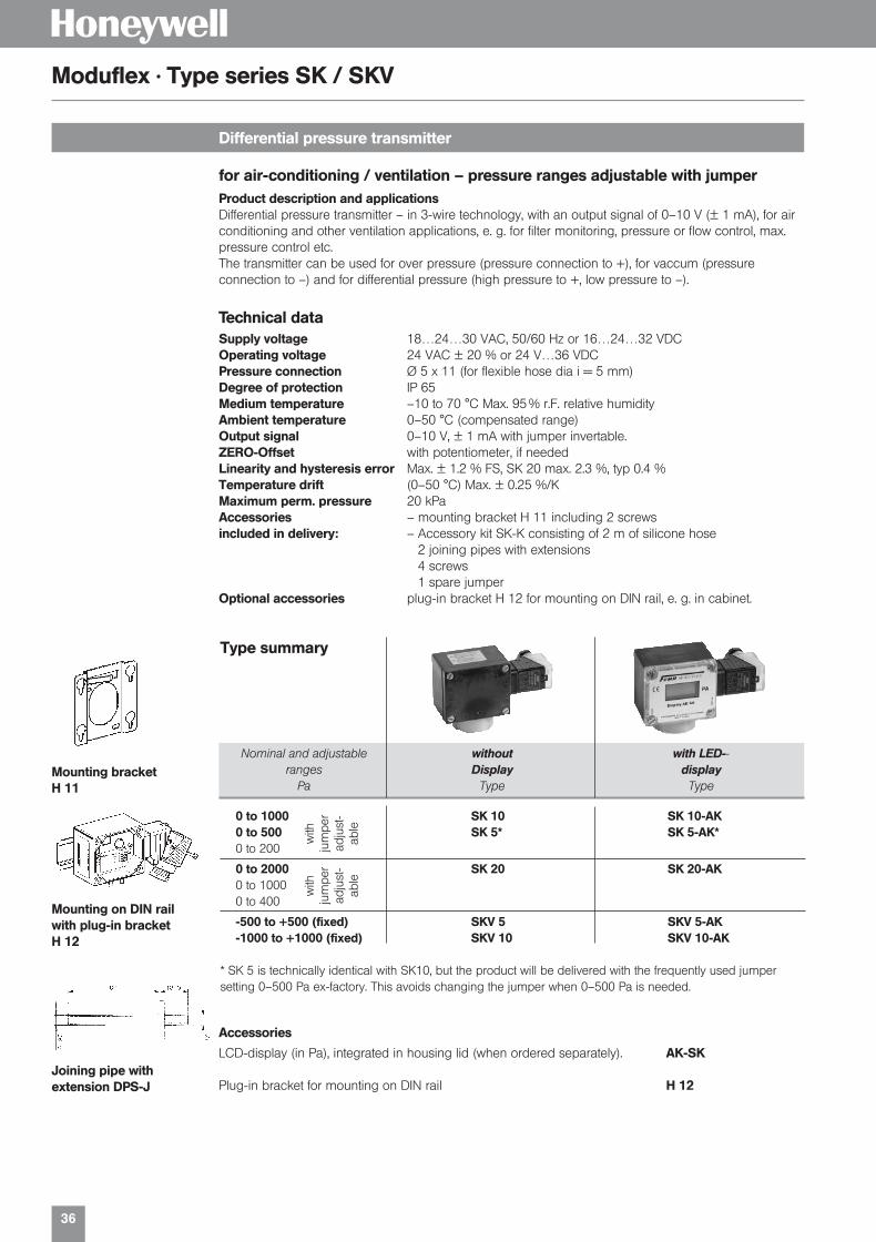
LCD-display (in Pa), integrated in housing lid (when ordered separately). AK-SK
Plug-in bracket for mounting on DIN rail H 12
Differential pressure transmitter
Moduflex · Type series SK / SKV
Product description and applicationsDifferential pressure transmitter – in 3-wire technology, with an output signal of 0–10 V (± 1 mA), for airconditioning and other ventilation applications, e. g. for filter monitoring, pressure or flow control, max. pressure control etc.The transmitter can be used for over pressure (pressure connection to +), for vaccum (pressureconnection to –) and for differential pressure (high pressure to +, low pressure to –).
Nominal and adjustable without with LED--ranges Display display
Pa Type Type
0 to 1000 SK 10 SK 10-AK0 to 500 SK 5* SK 5-AK*0 to 200
0 to 2000 SK 20 SK 20-AK0 to 10000 to 400
-500 to +500 (fixed) SKV 5 SKV 5-AK-1000 to +1000 (fixed) SKV 10 SKV 10-AK
* SK 5 is technically identical with SK10, but the product will be delivered with the frequently used jumpersetting 0–500 Pa ex-factory. This avoids changing the jumper when 0–500 Pa is needed.
Type summary
Mounting bracketH 11
Mounting on DIN railwith plug-in bracketH 12
Joining pipe withextension DPS-J
with
ju
mpe
rad
just
-ab
le
with
ju
mpe
rad
just
-ab
le
for air-conditioning / ventilation – pressure ranges adjustable with jumper
Technical dataSupply voltage 18…24…30 VAC, 50/60 Hz or 16…24…32 VDCOperating voltage 24 VAC ± 20 % or 24 V…36 VDCPressure connection Ø 5 x 11 (for flexible hose dia i = 5 mm)Degree of protection IP 65Medium temperature –10 to 70 °C Max. 95 % r.F. relative humidityAmbient temperature 0–50 °C (compensated range)Output signal 0–10 V, ± 1 mA with jumper invertable.ZERO-Offset with potentiometer, if neededLinearity and hysteresis error Max. ± 1.2 % FS, SK 20 max. 2.3 %, typ 0.4 %Temperature drift (0–50 °C) Max. ± 0.25 %/KMaximum perm. pressure 20 kPaAccessories – mounting bracket H 11 including 2 screwsincluded in delivery: – Accessory kit SK-K consisting of 2 m of silicone hose
2 joining pipes with extensions4 screws1 spare jumper
Optional accessories plug-in bracket H 12 for mounting on DIN rail, e. g. in cabinet.
01331_Product Catalog_02 19.02.2002 9:27 Uhr Seite 36

37
H
Differential pressure transmitter, piezoresistive
Type series DPT (D)
GeneralThe differential pressure transmitters of the DPT series are used for measuring differential pressure,positive pressure, and vacuum. The transmitters are suitable for:
Air-conditioning, Building automation Environmental protection Fan and blower control Valve and flap control Filter and blower monitoring Fluid and level monitoring Control of air flows
Working range Max. allowable Typepressure
-50 – +50 Pa 25 kPa DPT 50-100 – +100 Pa 25 kPa DPT 100
0 – 250 Pa 25 kPa DPT 2500 – 500 Pa 25 kPa DPT 5000 – 1000 Pa 25 kPa DPT 1000 0 – 2500 Pa 30 kPa DPT 25000 – 250 Pa 25 kPa DPT 250 D0 – 500 Pa 25 kPa DPT 500 D0 – 1000 Pa 25 kPa DPT 1000 D0 – 2500 Pa 30 kPa DPT 2500 D
Technical dataSupply voltage 18…24…30 VAC, 50/60 Hz or 16…24…32 VDCProtection class IP 54Process connection 6 mm hose pipeElectrical connection Screw terminal block for wire up to 1,5 mm2
Storage temperature –10…+70 °CHumidity 0…95 % r. H. (non condensing)Load ≤ 470 ΩLinearity and hysteresis ≤ ± 1 % FSResponse time 10 msLongterm stability typ. ± 0,5 % FS per yearTemperature drift 0…50 °C
DPT 50 (53)…500 (503) ± 5 % FSDPT 1000 (1003) ± 2,5 % FSDPT 2500 (2503)…5003 ± 1 % FS
Working range Max. allowable Typepressure
-50 – +50 Pa 25 kPa DPT 53-100 – +100 Pa 25 kPa DPT 103
0 – 250 Pa 25 kPa DPT 253 0 – 500 Pa 30 kPa DPT 5030 – 1000 Pa 25 kPa DPT 10030 – 2500 Pa 30 kPa DPT 25030 – 5000 Pa 50 kPa DPT 5003
Versions with 4–20 mA output signal
Versions with 0–10 V output signal
for gaseous, non-aggressive media
01331_Product Catalog_02 19.02.2002 9:27 Uhr Seite 37

H
38
01331_Product Catalog_02 19.02.2002 9:27 Uhr Seite 38

LON Pressure + Temperature
H
01331_Product Catalog_02 19.02.2002 9:27 Uhr Seite 39
40
H
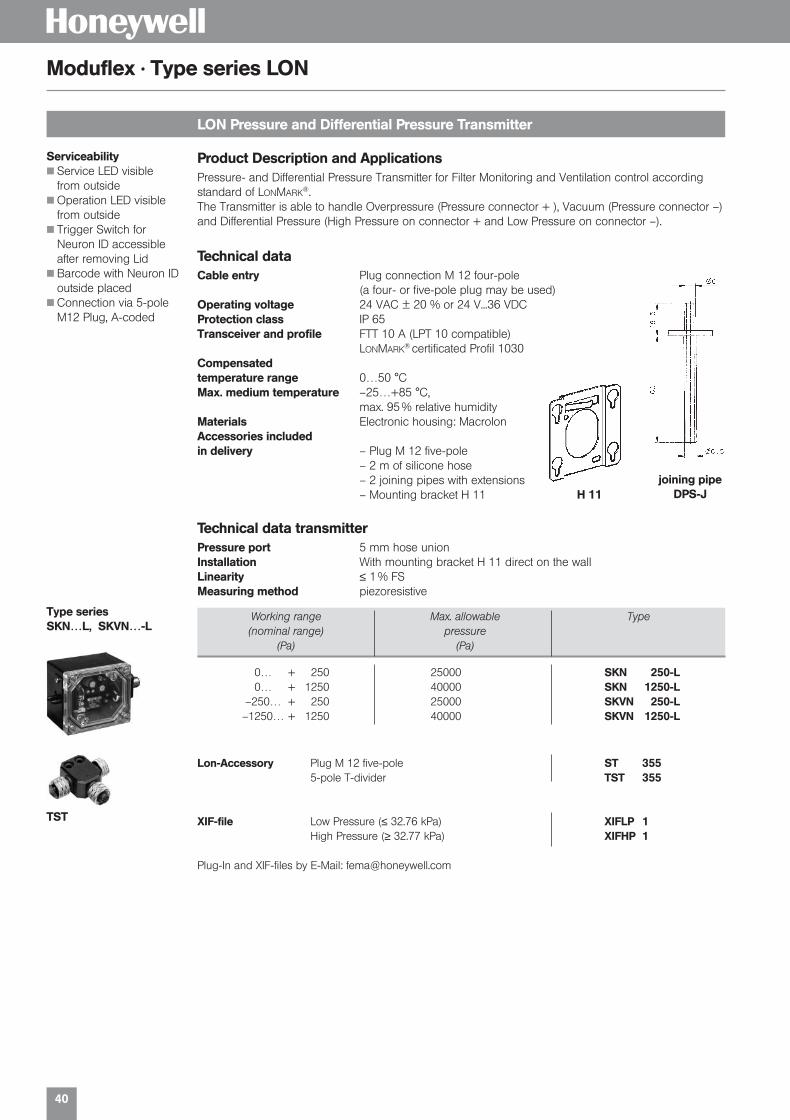
0… + 250 25000 SKN 250-L0… + 1250 40000 SKN 1250-L
–250… + 250 25000 SKVN 250-L–1250… + 1250 40000 SKVN 1250-L
LON Pressure and Differential Pressure Transmitter
Moduflex · Type series LON
Product Description and ApplicationsPressure- and Differential Pressure Transmitter for Filter Monitoring and Ventilation control accordingstandard of LONMARK®.The Transmitter is able to handle Overpressure (Pressure connector + ), Vacuum (Pressure connector –)and Differential Pressure (High Pressure on connector + and Low Pressure on connector –).
Technical dataCable entry Plug connection M 12 four-pole
(a four- or five-pole plug may be used)Operating voltage 24 VAC ± 20 % or 24 V...36 VDCProtection class IP 65 Transceiver and profile FTT 10 A (LPT 10 compatible)
LONMARK® certificated Profil 1030Compensated temperature range 0…50 °CMax. medium temperature –25…+85 °C,
max. 95 % relative humidityMaterials Electronic housing: MacrolonAccessories included in delivery – Plug M 12 five-pole
– 2 m of silicone hose– 2 joining pipes with extensions– Mounting bracket H 11
Serviceability Service LED visible
from outside Operation LED visible
from outside Trigger Switch for
Neuron ID accessibleafter removing Lid
Barcode with Neuron IDoutside placed
Connection via 5-poleM12 Plug, A-coded
H 11joining pipe
DPS-J
Technical data transmitterPressure port 5 mm hose unionInstallation With mounting bracket H 11 direct on the wallLinearity ≤ 1 % FSMeasuring method piezoresistive
Type seriesSKN…L, SKVN…-L
Working range Max. allowable Type(nominal range) pressure
(Pa) (Pa)
Lon-Accessory Plug M 12 five-pole ST 3555-pole T-divider TST 355
XIF-file Low Pressure (≤ 32.76 kPa) XIFLP 1High Pressure (≥ 32.77 kPa) XIFHP 1
Plug-In and XIF-files by E-Mail: [email protected]
TST
01331_Product Catalog_02 19.02.2002 9:27 Uhr Seite 40

41
H
Working range Working range Max. allowable Type(nominal range) (nominal range) pressure
(kPa) (bar) (kPa)
LON Pressure and Differential Pressure Transmitter for liquid and gaseous media
Moduflex · Type series LON
Common technical data SN and FHBN…-LCable entry Plug connection M 12 four-pole (a four- or five-pole plug may be used)Operating voltage 24 VAC ± 20 % or 24 V...36 VDCProtection class IP 65Transceiver and profile FTT 10 A (LPT 10 compatible) LONMARK® certificated, Profile 1030#Ambient temperature 0...+50 °CMaterials Electronic housing: MacrolonAccessories included – Plug M 12 five-polein delivery
Technical data SNPressure port G| male, Wrench size SW 27Materials Sensor housing: 1.4571, Pressure membrane: 1.4435Linearity ≤ 1 % FSPropagation delay ≤ 10 msMax. medium temperature –30…+100 °CInstallation The series SN sensors are fitted directly to the pipeline or the
pressure vessel
Features LONMARK®
pressure profile #1030
Uses Echelon LONTALK®
protocol
Direct mounting on thepressure line
Factory-configured defaultparameters
LON service and operation LED visible without disassembly
Protection class IP 65
Easy plug connection M12
Uses FTT 10A Transceiver
Barcode with Neuron IDoutside
0 … 25 0 … 0.25 75 SN 025-355-L0 … 100 0 … 1 300 SN 1-355-L0 … 250 0 … 2.5 750 SN 3-355-L0 … 600 0 … 6 1800 SN 6-355-L0 … 1000 0 … 10 3000 SN 10-355-L0 … 2500 0 … 25 7500 SN 25-355-L
Technical data FHBNPressure port G[ male femaleSensor material stainless steel 1.4571 / 1.4435Installation Direct on pressure line or wall mountingLinearity ≤ 2.5 % FSMax. medium temperature +70 °CMeasuring method Mechanical-inductive
Sensor load one direction
0 … 100 0 … 1 1000000 FHBN 1-355-L0 … 250 0 … 2.5 1500000 FHBN 3-355-L0 … 500 0 … 5 1500000 FHBN 5-355-L0 … 1000 0 … 10 1500000 FHBN 10-355-L
Accessories
Mail adapter union, brass G[ external thread with 8 mm outside diameter MAU 8 / Ms
Mail adapter union, stainless steel G[ ext. thread with 8 mm outside diameter MAU 8 / Nst
Shut-off valve combination, 3 venting valves VKD 3Shut-off valve combination, 5 venting valves VKD 5
SN…-355-L
FHBN…-355-L
Working range Working range Max. allowable Type(nominal range) (nominal range) pressure
(kPa) (bar) (kPa)
01331_Product Catalog_02 19.02.2002 9:27 Uhr Seite 41

42
H
LON Temperature Sensors
Moduflex · Type series LON
Application Temperature Transmitter for heating, district heating, air conditioning and ventilation according
standards of LONMARK®.
Fast medium temperature recording in district heating systems, solar circuits and cooling systems(T7425…).
Technical data LONCable entry Plug connection M 12 four-pole (a four- or five-pole plug may be used)Operating voltage 24 VAC ± 20 % or 24 VDC…36 VDCTransceiver and profile FTT 10 A (LPT 10 compatible), LONMARK® certificated, Profile 1040#Ambient temperature 0…50 °CMaterials Sensor housing: MacrolonAccessories included – Plug M 12 five-polein delivery – Immersion tube VFH-T (F) / VFL (F) to VF 20
Technical data SensorProtection class V…IP 54 (vertical mounting position)
L…IP 54 (vertical mounting position)T…IP 65
Installation V…directly in immersion tubeL…Flange mountingT…directly in pipeline
Measuring element NTC 20 kOhmLinearity Range
0…+75 °C ± 0.8 K–20…+100 °C ± 1.5 K–30…+140 °C ± 2.0 K
Technical data Series LF…-L, VF…-L, T…-L, AFF-L
Accessory LON
Working range Immersion depth Type(nominal range) (mm)
–30… + 100 °C 280 LF 20-L–20… + 110 °C 135 VF 20-T-L–20… + 110 °C 300 VF 20-L-L–20… + 110 °C 75 T7425 A 1005-L–20… + 110 °C 220 T7425 A 1013-L
0… + 70 °C – AFF -L
Immersion Tubes Immersion tube Cu/Ms for VF 20 T-L VFH-T (F)Immersion tube Cu/Ms for VF 20 L-L VFL (F)Immersion tube stainless for VF 20 T-L VFN-T (F)Immersion tube steel for VF 20 L-L VFL-N (F)
LON-Accessory Plug M 12 five-pole ST 3555-pole T-divider TST 355
XIF-file Temperature NTC XIFTN 1
Plug-In and XIF-file by E-Mail: [email protected]
TST
LF…L
AFF-L(Roomsensor)
T…-L(Fast sensor, usable
without immersion tube)
Serviceability Service LED visible from
outside Operation LED visible
from outside Trigger Switch for Neuron
ID accessible after remo-ving the lid
Barcode with Neuron IDon a housing placedsticker
Connection via 5-poleM12 Plug, A-coded
VF…L
01331_Product Catalog_02 19.02.2002 9:27 Uhr Seite 42
Temperature Sensors
H
01331_Product Catalog_02 19.02.2002 9:27 Uhr Seite 43

44
H
Two-phase frost protection
Type series FTS
Analog frost protectionWith falling temperature the frost protection generates a rising output signal 0–10 V.
Switching functionIf the temperature drops further, a limiter contact (single-pole changeover contact) is actuated.
Maximum selection for valve signalIf the output signal of the controller (Y signal) is looped through the frost protection, a maximum selection of the two signals takes place. If the Y signal from the controller is larger than the output signal of the frost protection, the controller determines the position of the heating valve (normal operation). If the output signal of the frost protection is larger than the Y signal of the controller (risk of frost), then the frost protection determines the position of the heating valve.
Self-monitoring sensorThe sensor acting over the entire length is self-monitoring, i. e. in the case of breakage or dama-ge of the capillary tube, “Risk of frost” is signaled. If the signal of the controller is not looped through, then the FTS outputs the frost control signal.
Cascades for large coilsFor very large heating coils several FTS can be used in cascade.
FTS
Technical dataSupply voltage 24 VAC ± 20 % or 24–36 VDCOutput signal 0–10 V + floating limiter contact (at falling temperature)Power consumption max. 1 WCable entry 2 x Pg 11 for electronic Large user friendly plug connection to
DIN 43650 for limit value switch.Degree of protection IP 65Installation With 2 size 4 mm screws directly one the duct wall.
5 capillary tube holders, Type H3 are included in the supply.Ambient temperature 12–50 °C
Caution: at ambient temperatures below 10 °C, the unit reacts andsignals “Risk of frost”.
Switching capacity 8 A 250 VAC
Range of action Capillary tube Type
10…3 °C 6 m FTS 01510…3 °C 3 m FTSB 015
Packaging includes 5 capillary tube holders Type H 3.
Characteristics
Terminal connection
1st phaseA = 10 °C Start of the working point (with falling temperature)
B = 5 °CEnd of the constant range
2nd phaseC = 4 °CSwitching back point of the limitercontact
D = 3 °CSwitching point of the limiter contact
with limiter contact and integrated priority selection
Block circuit diagramController
Connection diagramsPlug connection
01331_Product Catalog_02 19.02.2002 9:27 Uhr Seite 44

45
H
Immersion depth L Type(mm)
Temperature transmitters, Pt 100 made of high-grade steel sensor
Type series PZ 17
The temperature transmitters consist completely of stainless steel (tube 1.4571, transmitter housing 1.4301).The transmitter module is housed for easy access in the housing head and can also be replaced as required. A Pt 100, Class B (DIN IEC 751) is used as sensor.
Technical dataCable entry Pg 11Degree of protection IP 65Maximum temperature 60 °COperating voltage 12–36 VDCOutput signal 4–20 mA
Temperature rangesRange No.
–50 … + 50 °C 55–50 … + 100 °C 510 … 50 °C 500 … 100 °C 1000 … 200 °C 200
Higher temperature ranges (to 600 °C) on request.
Transmitter with immersion probe (screw-in thread)Screw in thread G|, 8 mm Ø
100 PZ 177-100/…150 PZ 177-150/…200 PZ 177-200/…250 PZ 177-250/…
Fastening flange R 187.Please add the identification code of the temperature range to the type No. Example: PZ 171-200/100Immersion tube R 185 see page 46.
Transmitter with air duct probe (not for humid and aggressive media) 8 mm Ø
output signal 4–20 mA (2-wire)
Immersion depth L Max. allowable pressure Type(mm) (bar)
100 40 PZ 171-100/…150 40 PZ 171-150/…200 35 PZ 171-200/…250 34 PZ 171-250/…
The pressure data apply up to a temperature of 250 °C.Immersion tube R 185 see page 46.
01331_Product Catalog_02 19.02.2002 9:28 Uhr Seite 45

46
HType series P 17
Immersion tube G || (only for P 171…, P 271… and PZ 171…)
Immersion depth Max. pressure Type Type(mm) (bar) Pt 1000 Pt 100
100 40 P 277-100 P 177-100150 40 P 277-150 P 177-150200 35 P 277-200 P 177-200250 35 P 277-250 P 177-250
Mounting flange R 187.
Air duct probe (not for humid and aggressive media) 8 mm Ø
Immersion depth (L) (mm) Type
100 R 185-100150 R 185-150200 R 185-200250 R 185-250
Mounting flange R 187for air duct probe, stainless steel 1.4571
R 187
R 18 R 185
Temperature sensors Pt 100 / Pt 1000 in stainless steel
The temperature sensors consist completely of high-grade steel (tube: 1.4571, terminal housing: 1.4301).
Technical dataSensor element Pt…, Class B to DIN IEC 751, 3-wire-connectionCable entry Pg 11Degree of protection IP 65Temperature range –50…600 °C
Immersion depth Max. pressure Type Type(mm) (bar) Pt 1000 Pt 100
100 40 P 271-100 P 171-100150 40 P 271-150 P 171-150200 35 P 271-200 P 171-200250 35 P 271-250 P 171-250
The pressure data apply up to a temperature of 250 °C.Immersion tube R 185.
Immersion probe with screw-in thread G || 8 mm Ø
01331_Product Catalog_02 19.02.2002 9:28 Uhr Seite 46
Thermostats + Hygrostats
H
01331_Product Catalog_02 19.02.2002 9:28 Uhr Seite 47

48
H
Technical data
Mechanical Thermostate
Normal version -version
…300 …700
Switching housing Aluminium diecast GDAISi 12 Aluminium diecast GDAISi 12
Switching function and Floating change-over contact. Floating change-over contact.connection drawing With rising pressure switching over With rising pressure switching over(applies only for version single-pole from 3–1 to 3–2. single-pole from 3–1 to 3–2.with microswitch)
Switching capacity 8 A at 250 VAC 3 A at 250 VAC(applies only for version 5 A at 250 VAC inductive 2 A at 250 VAC inductivewith microswitch) 8 A at 24 VDC 3 A at 24 VDC
0.3 A at 250 VDC 0.03 A at 250 VDC
Installation position arbitrary, verticalpreferably vertical
Degree of protection IP 65 IP 65(in vertical position)
Ex degree of protection – EEx de IIC T6 tested to EN50014/50018/50019 (CENELEC)
PTB-approval – Ex-90.C.1059
Electrical connection Terminal connection Terminal connection
Cable entry M 16 x 1,5 M 16 x 1,5
Ambient temperature –15 to +70 °C –15 to +60 °C
Switching point Adjustable with spindle Adjustable with spindle afterthe terminal box lid is removed.
Switching difference Adjustable or not adjustable Not adjustable(see type overview)
Medium temperature Max. 70 °C, briefly 85 °C Max. 60 °C
Vibration strength Up to 4 g no noteworthly deviations.
Isolation values Overvoltage category III, contamination class 3, reference surge voltage 4000 V.The conformity to DIN VDE 0110 (01.89) is confirmed.
Probe systems
Room probeTRM
Capillary tube probeTAM
Rod probeTX + R 1
Air duct probeTX + R 6
Frost protection probeFT
01331_Product Catalog_02 19.02.2002 9:28 Uhr Seite 48

49
H
Switch units / connection diagrams
Thermostats
Terminal connection Description Connection diagramsSeries 300
Normal versionmicroswitch, single pole changeover
ZFT 213 Gilded contactswith little transition resistance(e. g. for low tension)Cannot be supplied with adjustable switchingdifferential
ST 218 Plug connector with position indication12 V–240 VAC/DC
ZFT 351 Degree of protection IP 65with surface protectionHousing series 300(Terminal connections)
ZFT 513 EExi-versionhousing 300, cable entry and terminals blueGold plated contacts, degree of protection IP 65
ZFT 5970 Adjustment of one switching point according to customers instruction
ZFT 5971 Adjustment and sealing of switching points according to customers instruction
Example for ordering:TX 150-513
Code for optional function (minimum limiter)Code of temperature rangeType
01331_Product Catalog_02 19.02.2002 9:28 Uhr Seite 49

50
H
Range of adjustment Switching diff. Max. allowable Type(Mean value) temperature on sensor
Range of adjustment Switching diff. Max. permissible Type(Mean value) temperature on sensor
Industrial room thermostats
Type series TRM
Capillary tube thermostats with 1.5 m capillary tube
Type series TAM
Fema room thermostats are suitable for industrial plants, for greenhouses, stables, and warehouses,also for monitoring the maximum temperature in switchgear cabinets and relay stations.Room thermostats are supplied complete with H 1 wall bracket.
Switching differential not adjustable
-20/+20 °C 1.0 K 70 °C TRM 022-3010/+40 °C 1.0 K 70 °C TRM 40-301
+10/+50 °C 1.0 K 70 °C TRM 150-301
Switching differential adjustable
0/+40 °C 3–10 K 70 °C TRM 40-303+10/+50 °C 3–10 K 70 °C TRM 150-303
Switching differential not adjustable
-20/+20 °C 1.0 K 60 °C Ex-TRM 0220/+40 °C 1.0 K 60 °C Ex-TRM 40
+10/+50 °C 1.0 K 60 °C Ex-TRM 150
-version · Degree of protection EEx de IIC T6
The sensor cartridge at the end of the capillary tube is the actual active (temperature-sensitive) part ofthe sensor. Changes in temperature on the capillary tube have no effect on the switching point.Pressure -tight installation of the sensor in pressure vessels of all kinds is possible with the aid of immer-sion tubes.
Immersion tubes R….
Switching differential not adjustable
-20/+20 °C 1.5 K 110 °C TAM 022-301+10/+50 °C 1.5 K 110 °C TAM 150-301+40/+90 °C 2.0 K 125 °C TAM 490-301+80/+130 °C 2.0 K 150 °C TAM 813-301
-20/+20 °C 1.5 K 110 °C Ex-TAM 022+10/+50 °C 1.5 K 110 °C Ex-TAM 150+40/+90 °C 2.0 K 125 °C Ex-TAM 490+80/+130 °C 2.0 K 150 °C Ex-TAM 813
-version · Degree of protection EEx de IIC T6
TRM 40-301
TAM 490-301
Range of adjustment Switching diff. Max. allowable Type(Mean value) temperature on sensor
Range of adjustment Switching diff. Max. allowable Type(Mean value) temperature on sensor
01331_Product Catalog_02 19.02.2002 9:28 Uhr Seite 50
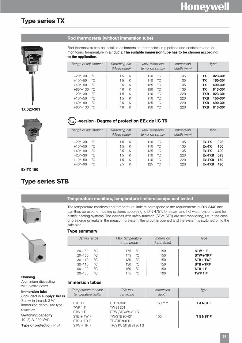
51
H
Rod thermostats (without immersion tube)
Type series TX
Temperature monitors, temperature limiters component tested
Type series STB
Rod thermostats can be installed as immersion thermostats in pipelines and containers and for monitoring temperature in air ducts. The suitable immersion tube has to be chosen according to the application.3650
Range of adjustment Switching diff. Max. allowable Immersion Type(Mean value) temp. on sensor depth (mm)
–20/+30 °C 1.5 K 110 °C 135 TX 023-301+10/+50 °C 1.5 K 110 °C 135 TX 150-301+40/+90 °C 2.5 K 125 °C 135 TX 490-301+80/+130 °C 4.0 K 150 °C 135 TX 813-301–20/+30 °C 1.5 K 110 °C 220 TXB 023-301+10/+50 °C 1.5 K 110 °C 220 TXB 150-301+40/+90 °C 2.5 K 125 °C 220 TXB 490-301+80/+130 °C 4.0 K 150 °C 220 TXB 813-301
Range of adjustment Switching diff. Max. allowable Immersion Type(Mean value) temp. on sensor depth (mm)
–20/+30 °C 1.5 K 110 °C 135 Ex-TX 023+10/+50 °C 1.5 K 110 °C 135 Ex-TX 150+40/+90 °C 2.5 K 125 °C 135 Ex-TX 490–20/+30 °C 1.5 K 110 °C 220 Ex-TXB 023+10/+50 °C 1.5 K 110 °C 220 Ex-TXB 150+40/+90 °C 2.5 K 125 °C 220 Ex-TXB 490
-version · Degree of protection EEx de IIC T6
TX 023-301
Ex-TX 150
The temperature monitors and temperature limiters correspond to the requirements of DIN 3440 andcan thus be used for heating systems according to DIN 4751, for steam and hot water systems and fordistrict heating systems. The devices with safety function (STW, STB) are self-monitoring, i. e. in the caseof breakage or leaks in the measuring system, the circuit is opened and the system is switched off to thesafe side.
Type summary
Setting range Max. temperature Immersion Typeat the probe depth (mm)
20–150 °C 175 °C 150 STW 1 F20–150 °C 175 °C 150 STW + TRF30–110 °C 130 °C 150 STB + TWF30–110 °C 130 °C 150 STB + TRF60–130 °C 150 °C 150 STB 1 F20–150 °C 175 °C 100 TWP 1 F
HousingAluminium diecasting with plastic cover
Immersion tube(included in supply): brassScrew-in thread: G|
Immersion depth: see typeoverview
Switching capacity10 (2) A, 250 VAC
Type of protection IP 54
Temperature monitor, TÜV-test Immersion Typetemperature limiter certificate depth
STB 1 F STB 89 501 150 mm T 4 NST FTWP 1 F TW 89 201STW 1 F STW (STB) 89 401 SSTB + TW F TW/STB 90 401 150 mm T 5 NST F STB + TR F TR/STB 90 001STW + TR F TR/STW (STB) 89 901 S
Immersion tubes
01331_Product Catalog_02 19.02.2002 9:28 Uhr Seite 51

52
H
Frost protection thermostats
Type series T69
Frost protection thermostats for air heating and conditioning systems
Type series FT
If the temperature falls below the set value over a min. length of 3–5 cm, the thermostat switches off.A fixed stop on the setting spindle at 4 °C prevents the thermostat from being set below the freezingpoint due to in expert adjustment. If the capillary tube is damaged or broken, the Fema frost protection thermostats reliably switch off towards the safe side (e. g. fan off), irrespective of the temperature at thesensor. Capillary tube holders H 3 are included.
Range of adjustment Max. temperature Version Typeon sensor
4–15 °C 200 °C 6 m capillary tube FT 0154–15 °C 200 °C 3 m capillary tube FTB 015
Version with manual reset4–15 °C 200 °C 6 m capillary tube FT 015-2064–15 °C 200 °C 3 m capillary tube FTB 015-206
Plug connection to DIN 43650
4–15 °C 200 °C 6 m capillary tube Ex-FT 0154–15 °C 200 °C 3 m capillary tube Ex-FTB 015
Two-phase frost protection control system with output signal 0–10 V and limit switch.
-version · Degree of protection EEx de IIC T6
large service friendly plug
easy check of correctconnection by removingthe plug
Reheaters in air conditioning systems Heat exchanger in cooling systems Gas-filled copper sensible element with 1.8 m
bulb length or 3 m and 6 m coil length Dust-tight (Honeywell) micro switch the
switching contacts (heat/cool)
Protection class I (T6950/51) accordingEN60335-1, IP40 according EN60529
Easy installation and wiring Manual Reset (T6950/60), Automatic Reset
(T6951A/61A) all 1.8 m versions with immersion bulb
The Single Stage Thermostat series T6950A/51A/60A/61A provides the antifreeze function. Designedfor systems where temperature may not drop under a certain fixed safety value such as:
Range of adjustment–10 °C…+12 °C
Max. overload temperature200 °C (max. 60 min.)
Housing materialABS and corrosion protec-ted steel (IP65 Macrolon)
Switching capacity24…250 VAC; 18 (8) A
Hysteresis1 K
Type of protection Length of capillary tube TypeIP m
40 1.8 m T6951A100940 3.0 m T6951A101740 6.0 m T6951A102565 1.8 m T6961A100765 3.0 m T6961A101565 6.0 m T6961A1023
Frost protection thermostats
Type of protection Length of capillary tube TypeIP m
40 1.8 m T6950A100040 3.0 m T6950A101840 6.0 m T6950A102665 1.8 m T6960A100865 3.0 m T6960A101665 6.0 m T6960A1024
Frost Protection Limiter (with internal interlock)
T69
FT015
01331_Product Catalog_02 19.02.2002 9:28 Uhr Seite 52

53
H
TKM 50-315
Strap-on thermostats for underfloor heating
Type series TKM
Self-monitoringFeatures Self monitoring sensor Solid, robust housing Easy installation Heat compound and
tension band| to 2 included
Description The fast responding sensor system is also self-monitoring. If the sensor is broken or damaged, the thermostat behaves as though the temperature had exceeded the set value it switches off towards thesafe side (e.g. circulating pump off). The response sensitivity can be improved by using a heat conducting compound between the pipe and the contact face of the sensor. Heat conducting compound is included with each unit. It is important that the surface of the pipe is carefully cleaned and free from dirt, scale and paint beforefitting the sensor. The tension band included with each thermostat enables the contact thermostats to beattached to pipes of nominal diameters | to 2.
Type selection for underfloor heating applicationsThe switching point should be 10 K above the temperature of the underfloor heating systems.
Technical dataCasing Aluminium die-cast GD AI Si 12 according to DIN 1725.
Terminal box lid made of glass fibre reinforced plastic.Mounting position OptionalFitting With tension band directly on the pipe. Suitable for nominal
diameters of pipe from | to 2.Max. Ambient temperature 70 °CMax. Temperature at the sensor 100 °CSwitching temperature Adjustable with screwdriver after removal of the terminal box cover.
For ranges see summary of types.Switching differential Not adjustable. For values see summary of types.Contact complement Single-pole changeover. Two-pole version on enquiry.Switching capacity 8 (5) A 250 VACType of protection IP 54 according to DIN 40050 (in case of vertical mounting)Connection 3-pole terminal strip and earth conductor connection. Accessible
after removal of the terminal box cover. Cable entry Pg 11, max.cable diameter 10 mm.
Adjustment The specified setting values relate to the upper switching point(with rising temperature). The lower switching point (with fallingtemperature) is lower by the switching differential.
Range of adjustment Switching differential Factory-set Type(Mean Values) at
45–50 °C 6 K 50 °C TKM 50-31555–60 °C 6 K 60 °C TKM 60-31565–70 °C 6 K 70 °C TKM 70-315
Summary of types
Connection diagram
01331_Product Catalog_02 19.02.2002 9:28 Uhr Seite 53

54
H
Single and Dual Stage Industrial Room Thermostats T6120 A/B
Industrial Room Thermostats
General Application The T6120A and B Single- and Dual-Stage Industrial Room Thermostats are designed for measuring,monitoring, and controlling temperatures in heating and cooling systems. These thermostats are suitablefor the following areas of applications.
commercial buildings garages factories
storage rooms machine rooms
greenhouses and agricultural installations
Technical data T6120A1005 T6120B1003
Max. current 10 (1,5) A, 250 VAC 15 (8) A, 24…250 VACMax. bulb temperature +65 °C +60 °CSwitching differential 1 °C 1 °CProtection standard IP 54 IP 65Weight 360 g 530 gDifference between 2 stages – 2…10 KHousing material glass fibre reinforced ABSElectrical connection Screw terminal block for wiring up 1,5 mm2
Wiring and function T6120A1005
HeatingConnect terminal 2 and terminal 3. The contact opens while the temperature is increasing.
CoolingConnect terminal 1 and 2. The contact opens while the temperature is decreasing.
Order No. Stage Housing temperature Temperature range
T6120A1005 single -10…+65 °C 0…+40 °CT6120B1003 dual -15…+60 °C -30…+30 °C
Wiring and function T6120B1003
HeatingConnect Red (common) to blue terminal; the contact opens while rising of the temperature in the following sequence: Stage 2, Stage 1.
CoolingConnect Red (common) to white terminal; the contact opens while dropping of the temperature in the following sequence: Stage 1, Stage 2.
Differential setting
Switching differential between both stages can be adjusted by a inside setpoint lever mounted belowthe mircro switch “stage 2”.Turning the lever to the sensor side means – increase of switching differentialTurning the lever to the cable entry side means – degrease of switching differential
T6120A1005
01331_Product Catalog_02 19.02.2002 9:28 Uhr Seite 54

5555
H
Duct and Room Hygrostats H6045, H6120
Hygrostats
General Application The H6045A1002 Single-Stage Duct Hygrostat and the H6120A1000 Single-Stage Room Hygrostat aredesigned for monitoring relative humidity in air conditioning systems and climatic cabinets as well as forcontrolling air humidifiers and dehumidifiers for dehumidification control in Indoor swimming pools.Further areas of application include storage rooms for foodstuffs, the textiles industry, paper industry,printing shops, the film industry, greenhouses, hospitals and wherever air humidity levels must be monitored.
Mounting and Switch Point Adjustment
H6045A1002The H6045A1002 Duct Hygrostat can be installed directly onto air ducts using the attached mountingbracket.
H6120A1000The H6120A1000 Room Hygrostat must be mounted far from heat sources and must be freely accessi-ble for air convection at a height of approx. 1.5 meters.
Switch Point AdjustmentThe switch point can be adjusted using the knob located on the top of the device. The easily readablescale and the pointer on the housing surface facilitate adjusting the humidity level.
Specification H6045A1002 Duct Hygrostat H6120A1000 Room Hygrostat
Humidity range 35…100 % r. H. 35…100 % r. H.
Switch load 15 (8) A, 24…250 VAC 5 (0.2) A, 230 VAC
Contact single-pole single-pole
Max. working temperature -10…+65 °C 0…+60 °C
Max. air-flow speed 8 m/s 15 m/s
Protection standard IP 65 IP 30
Protection class I I
Tolerance max. 4 % r. H. max. 3 % r. H.
Switching hysteresis 5 % r. H. 4 % r. H.
Housing material ABS glass fiber reinforced ABS (white)
Weight 480 g 125 g
Technical dataH6045A1002
H6120A1000
01331_Product Catalog_02 19.02.2002 9:28 Uhr Seite 55

H
56
01331_Product Catalog_02 19.02.2002 9:28 Uhr Seite 56

Flow Monitor ing
H
01331_Product Catalog_02 19.02.2002 9:28 Uhr Seite 57
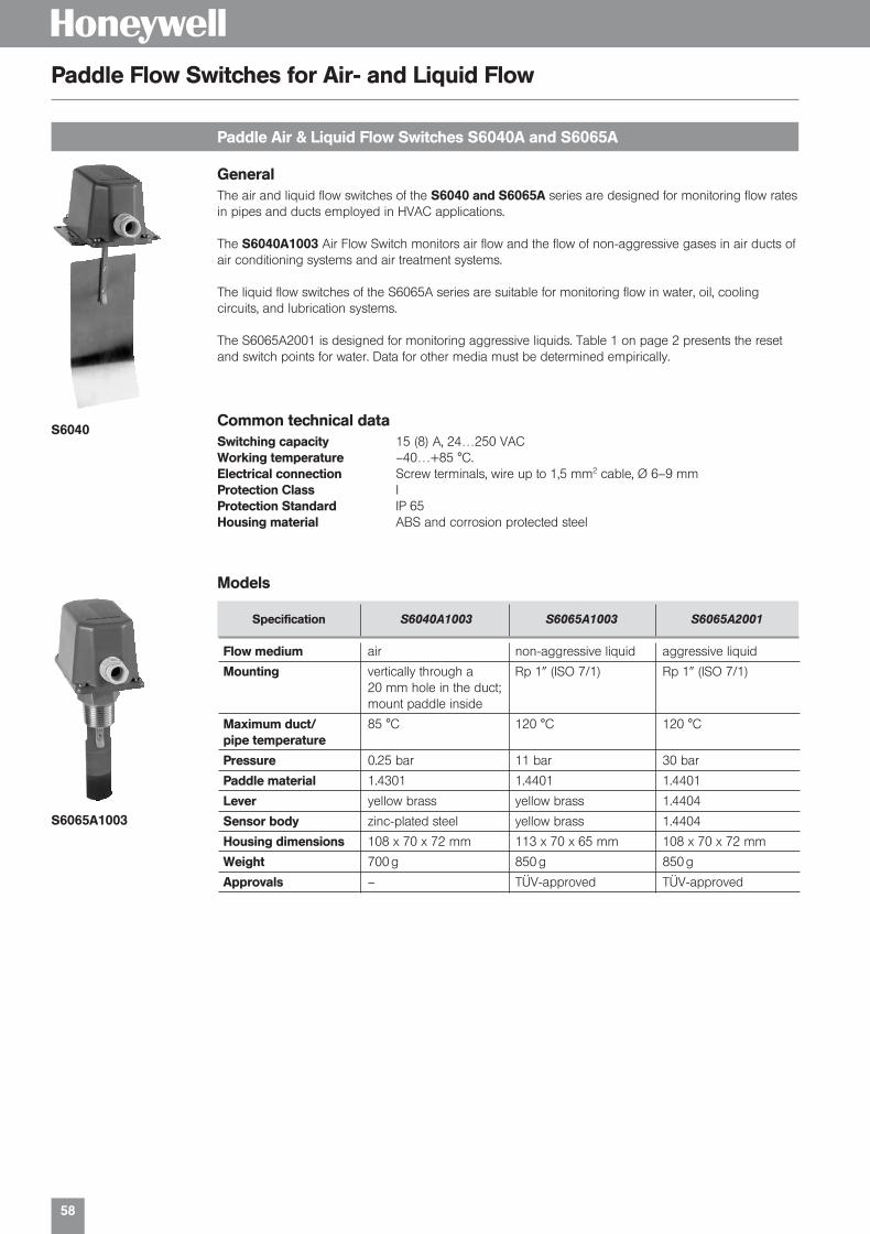
58
H
Common technical dataSwitching capacity 15 (8) A, 24…250 VACWorking temperature –40…+85 °C.Electrical connection Screw terminals, wire up to 1,5 mm2 cable, Ø 6–9 mmProtection Class IProtection Standard IP 65Housing material ABS and corrosion protected steel
Models
Specification S6040A1003 S6065A1003 S6065A2001
Flow medium air non-aggressive liquid aggressive liquid
Mounting vertically through a Rp 1 (ISO 7/1) Rp 1 (ISO 7/1)20 mm hole in the duct;mount paddle inside
Maximum duct/ 85 °C 120 °C 120 °Cpipe temperature
Pressure 0.25 bar 11 bar 30 bar
Paddle material 1.4301 1.4401 1.4401
Lever yellow brass yellow brass 1.4404
Sensor body zinc-plated steel yellow brass 1.4404
Housing dimensions 108 x 70 x 72 mm 113 x 70 x 65 mm 108 x 70 x 72 mm
Weight 700 g 850 g 850 g
Approvals – TÜV-approved TÜV-approved
Paddle Air & Liquid Flow Switches S6040A and S6065A
Paddle Flow Switches for Air- and Liquid Flow
General The air and liquid flow switches of the S6040 and S6065A series are designed for monitoring flow ratesin pipes and ducts employed in HVAC applications.
The S6040A1003 Air Flow Switch monitors air flow and the flow of non-aggressive gases in air ducts ofair conditioning systems and air treatment systems.
The liquid flow switches of the S6065A series are suitable for monitoring flow in water, oil, cooling circuits, and lubrication systems.
The S6065A2001 is designed for monitoring aggressive liquids. Table 1 on page 2 presents the resetand switch points for water. Data for other media must be determined empirically.
S6040
S6065A1003
01331_Product Catalog_02 19.02.2002 9:28 Uhr Seite 58

59
H
Flow monitoring in liquids and gases
Type series SWW
Technical dataMaterials In contact with medium: stainless steel 1.4571
Sealing compound: Wepuran (vu 4459/41 sv)Cable screw union: Ms nickel-plated
Cable length 2,5 mDegree of protection IP 65 (Sensor), IP 32 (evaluation unit)Medium temperature 0…80 °C (compensated range), max. permissible to 120 °C.
Evaluation unitSwitching output Relay 8 A, 250 VACPower consumption app. 3 VASensitivity 0.1…3 m/s in fluid media,
1…15 m/s in gaseous mediaDelay time approx. 10–60 sProbe breakage protection On breakage or interruptionType of construction Standard housing N 45
The flow in fluids can be monitored reliably with the flow sensor SWF 62 and the evaluation unit ASW…The sensitivity can be adjusted accurately with a coarse and fine potentiometer. The switching state isindicated by LED. The sensor element must be located in the flow.
max. 60 m
shielded cable
4 x 1,5 mm2
Type summary Screw-in thread supply voltage Type
Sensor G[ SWF 62
G| SWF 62L
Evaluation units 230 VAC ASW 454
24 VAC / DC ASW 454 / 24
Type summary Supply voltage Type
230 VAC KSW 23024 VAC / DC KSW 24
Compact Electronic Air and Liquid Flow SwitchThe high reliable Compact Electronic Flow Switches are designed for detecting water Flow in pipes. As soon as medium flow speed exceeds or falls under a customer adjusted value, the device will switch aelectric cirquit.
Technical dataSensor materials in contact with medium; Stainless steel 1.4305
Sealing compounds: Wepuran (vu4459/41sv)Process Connection G|Housing IP 65Medium temperature -10…+ 80°CTemperature compensation: 80 °C, Temp. (up to 120 °C) may cause a deviation of the switching point,
but cannot destroy the sensor.Max. Pressure 30 barPower supply 230 VAC, 24 VAC /DCContact Load relay, single pole, double tap (SPDT) 250 VAC, 10 (2) ARange 0,05…3 m/sResponse time 1–10 s on Flow speedSensor protection In case of failure of sensor or power supply and shortcut, the relay will
switch off (to the safe side)
KSW 230
Flow monitoring
Type series KSW
01331_Product Catalog_02 19.02.2002 9:28 Uhr Seite 59

60
H
Air flow monitoring
Type series KSL
Type summary Power supply Type
230 VAC KSL 23024 VAC / DC KSL 24
Compact Electronic Air and Liquid Flow SwitchThe high reliable Compact Electronic Flow Switches are designed for detecting air flow in ducts.
As soon as medium flow speed exceeds or falls under a customer adjusted value, the device will switch aelectric cirquit.
Technical dataSensor Fast acting air flow sensor with adjustable air duct mounting flange. The
sensing element is insensitive to humidity. (Cleaning of the sensor elementwith flow water is possible.)
Immersion depth 130 mmHousing IP IP 65Medium temperature –20…+80°CTemperature compensation Fast, latest 0,3 sec after change of temperatureSensor material MS58 Nickel platedMax. Pressure 10 barPower supply 230 VAC, 24 VAC /DCContact load Relais, single pole, double tap (SPDT), 250 VAC, 10 (2) AResponse time 1…10 sec. depending on Flow speedSensor protection In case of mechanical failure of sensor or power supply and shortcut, the
relais will switch off (to the safe side).
KSL 230
Air flow monitoring
Type series SWL
Technical dataDepth of immersion 35 mmDegree of protection IP 32Medium temperature –20. . .+120 °C
Evaluation unitSwitching output Relay 8 A, 250 VACPower consumption approx. 3 VASensitivity 0.1…20m/sDelay time approx. 1 sProbe breakage protection On breakage or interruptionType of construction Standard housing N45
While the plant is being started up (still no airflow present), the output contact is activated and the flowcondition signalled. The time for the switch-on bypass is adjustable from 2-60 s.
max. 100 m
shielded cable
3 x 1,5 mm2
Type summary Supply voltage Type
Sensor (with flange) SLF 3
Evaluation units 230 VAC ASL 45324 VAC / DC ASL 453 / 24
01331_Product Catalog_02 19.02.2002 9:29 Uhr Seite 60

Solenoid Valves
H
01331_Product Catalog_02 19.02.2002 9:29 Uhr Seite 61

62
H
Technical data overview
Solenoid valves, coupled, also in
Fema piston-type solenoid valves are suitable for exacting fields, especially in the field of heat, energyand gas technology. All the below mentioned product groups are coupled and therefore used from 0 bar to maximal pressure, a minimum differential pressure is not necessary. A DC coil is universallyused. For connection to an AC supply of 230 V, a rectifier is be supplied. The rectifier is installed at theplug connection. The valves are to be used in correct direction of flow only. If flow is reversed, valves willnot close completely. The valves need to be operated once per month for correct functioning.
Series Nom. M = Working Seals Temperatures N = Opera- Testingdiameter Sockets pressure* Medium Environ- Normal-type ting agency
DN F = Piston Nozzle Static ment Ex = modes DINApplication (mm) Flange (bar) Seal °C °C Ex-type
TG 15/20 M + F 0–40 -15 to -15 to N ncfor neutral 25/32 M + F 0–32 NBR NBR NBR + 90 + 60 + +media 40/50 F 0–20 60°C at Ex no
TGK 15/20 M + F 0–40 PTFE stainl. EPDM max. 180 -15 to N ncfor high 25/32 M + F 0–32 steel + 60 +temperatures 40/50 F 0–20 conne no
K 15/20 M 0–4 -15 to -15 to Nfor fuel gases 15/20 F 0–4 NBR NBR NBR +60 +60 + nc DVGWup to 4 bar 25/32 F 0–4 DIN-EN
40/50 F 0–4 161
K 15/20 F 0–25 -15 to -15 to N DVGWfor fuel gases 25/32 F 0–25 NBR NBR NBR +60 +60 + nc DIN 3394higher than 40/50 F 0–20 part 14 bar
Kfor liquid 15/20 F 0–25 NBR NBR NBR -15 to -15 to N TÜVgas in liquid 25 F 0–25 +60 +60 + nc DIN 32725phase (draft
Nov ´92)
K 15/20 F 0–25 -15 to 15 to TÜVfor fuel oil 15/32 F 0–25 NBR NBR NBR +60 +60 N nc DIN-EN
40/50 F 0–20 264
LGfor hot water 15/20 M + F 0–25 stainl. +4 to TÜVand steam 25/32 M + F 0–20 PTFE steel EPDM max. 120 +60 N nc DIN 32730up to 120 °C 40/50 F 0–16 conne
LGKfor hot water 15/20 M + F 0–20 stainl. +4 to TÜVand steam 25/32 M + F 0–16 PTFE steel EPDM max. 180 +60 N nc DIN 32730up to 180 °C 40/50 F 0–12 conne
nc = normally closed, opened under voltage.no = normally open, closed under voltage (identified in the type review by “U”).* = The respective data sheet contains exact details of the limits of use.
Sealing materials:NBR = Buna N (Perbunan)EPDM = Ethylene – propylene – rubberPTFE = Teflon
Certificates to EN 10 204/Documents
WZ 2.2 Test report 2.2 type series certificate
AZ 3.1 B-M AZ 3.1 B inspection certificate specific product test
DOKU Documents: additional documents, e.g. data sheets, mounting,instructions, TÜV-, DVGW- or PTB-certificate.
01331_Product Catalog_02 19.02.2002 9:29 Uhr Seite 62

63
H
Solenoid valves for universal application
Solenoid valves
Type series TG
Solenoid valves in -version
Type series TG-Ex
Technical dataType 2/2-wayType of construction Piston-type solenoid valve, coupled, minimum differential pressure not necessaryMaterials Casing: Bronze Rg 5 to DIN 1705, Internal parts: Brass (CuZn) and corrosion-resi-
stant steel, Sealing: Perbunan (normal version)Mounting position Solenoid system uprightMagnet System / The standard magnet systems have DC coils. For AC connections a built-inelectr. connection rectifier is supplied with the valve. The magnet coil is cast into silicone rubber
(a moisture protection)Operating voltage 230 VAC, 50 HzDegree of protection IP 65 to DIN 40 050, fr = suitable for outdoor usePower Requirement about 47 VA (with the magnet warmed)Duty Cycle 100 % EDDegree of protection Pressure proof capsule EEx de IIC T5 (PTB-No. Ex-85/1063). on Ex-versions Suitable for ≥ Zone 1 and 2 areasPressure ranges as well as medium resp. ambient temperatures see type overview.
The piston type solenoid also can open and close even in the pressureless state and with low differential pressures. Ambient temperature –15 °C up to 60 °C. Temperature of medium up to 90 °C (120 °C). Degree of protection IP 65. (Rectifier is built into the connection plug).
Operating mode: normally closed, on desire, normally open.
DN kVS-value Working pressure Internal Type(mm) (m3/h) (bar) thread
Operating mode: normally closed
15 4.0 0–30 G| T15G31M20 4.8 0–30 G T20G31M25 10.0 0–25 G 1 T25G31M32 13.0 0–25 G1[ T32G31M
15 4.0 0–30 T15G31F20 4.8 0–30 T20G31F25 10.0 0–25 T25G31F32 13.0 0–25 Flange T32G31F40 34.0 0–16 T40G31F50 40.0 0–16 T50G31F
DN kVS-value Working pressure Internal Type(mm) (m3/h) (bar) thread
Operating mode: normally closed
15 4.0 0–30 G| T15G35M-Ex20 4.8 0–30 G T20G35M-Ex25 10.0 0–25 G 1 T25G35M-Ex32 13.0 0–25 G 1[ T32G35M-Ex
15 4.0 0–30 T15G35F-Ex20 4.8 0–30 T20G35F-Ex25 10.0 0–25 T25G35F-Ex32 13.0 0–25 Flange T32G35F-Ex40 34.0 0–16 T40G35F-Ex50 40.0 0–16 T50G35F-Ex
Suitable for explosion hazardous rooms (≥ zone 1). Pressure proof encapsulated (EEx de IICT5) PTB-No. Ex-85/1063. Maximum medium resp. ambient temperature 60 °C. Rectifier is built into the connection plug.Operating mode: normally closed, on desire, normally open.
T15G31M
T32G35F-Ex
01331_Product Catalog_02 19.02.2002 9:29 Uhr Seite 63

64
H
Solenoid valves for gas, liquid gas and liquid fuels
Type series K
Suitable for all gases according DVGW-data sheet G 260, for liquid phase (up to DN 25) and for fuel oil.Minimum differential pressure is not necessary. The solenoid valves are also available with a pressure-tightsolenoid system (Protection Class EEx de IIC T5, PTB-No. Ex-85/1063)
Operating mode: normally closed.
DN kVS- Working Nominal Con- Registration Valves Typevalue pressure pressure nection class
(mm) (m3/h) (bar) PN
15 4.0 0– 4 G| 1, 5 B K15G31M20 4.8 0– 4 G 1, 5 B K20G31M
15 4.0 0–25 40 1, 2, (3), 4, 5, 6 B K15G31F20 4.8 0–25 40 1, 2, (3), 4, 5, 6 B K20G31F25 10.0 0–25 40 1, 2, (3), 4, 5, 6 B K25G31F32 13.0 0–25 40 1, 2, 4, 5, 6 B K32G31F40 34.0 0–20 25 1, 2, 4, 5, 6 C K40G31F50 40.0 0–20 25 1, 2, 4, 5, 6 C K50G31F
Flan
ge
15 4.0 0– 4 G| 1, 5 B K15G35M-Ex20 4.8 0– 4 G 1, 5 B K20G35M-Ex
15 4.0 0–25 40 1, 2, (3), 4, 5, 6 B K15G35F-Ex20 4.8 0–25 40 1, 2, (3), 4, 5, 6 B K20G35F-Ex25 10.0 0–25 40 1, 2, (3), 4, 5, 6 B K25G35F-Ex32 13.0 0–25 40 1, 2, 4, 5, 6 B K32G35F-Ex40 34.0 0–20 25 1, 2, 4, 5, 6 C K40G35F-Ex50 40.0 0–20 25 1, 2, 4, 5, 6 C K50G35F-Ex
Flan
ge
-version
Registrations:
K25G35F-Ex
K25G31F
se
DIN-DVGW
DIN-EN
Type series Test Standard Reg.-Number Notified Body
K15G35F-Ex, K20G35F-Ex, DIN EN 161 CE-0085AN0073 DVGWK25G35F-Ex, K32G35F-Ex,K40G35F-Ex, K50G35F-Ex
K15G31F, K20G31F, DIN EN 161 CE-0085AN0072 DVGWK25G31F, K32G31F,K40G31F, K50G31F
K15G31M, K20G31M, DIN EN 161 CE-0085AN0074 DVGW
K15G35M-Ex, K20G35M-Ex DIN EN 161 CE-0085AN0075 DVGW
K15G31F, K20G31F, DIN EN 264 5S038/97 DIN CERTCOK15G35F-Ex, K20G35F-Ex,K15G31M, K20G31MK15G35M-Ex, K20G35M-Ex
K25G31F, K25G35F-Ex, DIN EN 264 5S039/97 DIN CERTCOK32G31F, K32G35F-Ex
K40G31F, K50G31F, DIN EN 264 5S040/97 DIN CERTCOK40G35F-Ex, K50G35F-Ex
K15G31F, K20G31F, DIN 32725 E Test Nr. S 78/95 TÜVK15G35F-Ex, K20G35F-Ex
K25G31F, K25G35F-Ex, DIN 32725 E Test Nr. S 79/95 TÜV
Valves K…F Ü, List A, T. 1, Test Nr. S 162/95 TÜV95/1
01331_Product Catalog_02 19.02.2002 9:29 Uhr Seite 64

65
H
Solenoid valves for medium temperature up to 180 °C
Type series TG-K
Solenoid valves for hot water and steam up to 120 °C/180°C
Type series LG
The piston-type solenoid valves of the TGK series are suitable for hot water, steam, fuel oil and othernon-aggressive media up to a temperature of 180 °C.Operating mode: normally closed, on desire normally open.
DN kVS-value Working pressure Internal Type(mm) (m3/h) (bar) thread
15 4.0 0–25 G| T15G31MK20 4.8 0–25 G T20G31MK25 10.0 0–20 G 1 T25G31MK32 13.0 0–20 G 1[ T32G31MK
15 4.0 0–25 T15G31FK20 4.8 0–25 T20G31FK25 10.0 0–20 T25G31FK32 13.0 0–20 Flange T32G31FK40 34.0 0–16 T40G31FK50 40.0 0–16 T50G31FK
Tested to DIN 32730Fema piston-type solenoid valves of the LG series are particularly suitable for use as stop and safetycheck valves in heating installations up to 120 °C resp. 180 °C. The coupled (automatically servo-controlled) mode of operation does not require a minimum differential pressure; the units can open andclose perfectly even in the pressureless state and with low differential pressures.Operating mode: normally closed.
L25G31F
DN kVS-value Working pressure Internal Max. medium Type(mm) (m3/h) (bar) thread temperature
15 4.0 0–25 G| L15G31M20 4.8 0–25 G L20G31M25 10.0 0–20 G 1 120 °C L25G31M32 13.0 0–20 G 1[ L32G31M
15 4.0 0–25 L15G31F20 4.8 0–25 L20G31F25 10.0 0–20 L25G31F32 13.0 0–20 Flange 120 °C L32G31F40 34.0 0–16 L40G31F50 40.0 0–16 L50G31F
15 4.0 0–20 G| L15G31MK20 4.8 0–20 G L20G31MK25 10.0 0–16 G 1 180 °C L25G31MK32 13.0 0–16 G 1[ L32G31MK
15 4.0 0–20 L15G31FK20 4.8 0–20 L20G31FK25 10.0 0–16 L25G31FK32 13.0 0–16 Flange 180 °C L32G31FK40 34.0 0–12 L40G31FK50 40.0 0–12 L50G31FK
T40G31FK
Registration
Type series Test Standard Reg.-No. Notified Body
L15G31MK, L15G31FK, L20G31MK, L20G31FK DIN 32730 1F01999 DIN CERTCO
L25G31MK, L25G31FK, L32G31MK, L32G31FK DIN 32730 1F02099 DIN CERTCO
L40G31FK, L50G31FK DIN 32730 1F02199 DIN CERTCO
L15G31M, L15G31F, L20G31M, L20G31F DIN 32730 1F02299 DIN CERTCO
L25G31M, L25G31F, L32G31M, L32G31F DIN 32730 1F02399 DIN CERTCO
L40G31F, L50G31F DIN 32730 1F02499 DIN CERTCO
Valves L…F Ü, List A, T. 1, 95/1 Test No. TÜVS 160/95
01331_Product Catalog_02 19.02.2002 9:29 Uhr Seite 65

66
H
for valves
Accessories for Solenoid Valves
If not identified specially, the valves are delivered with “closed at zero current” mode of operation.Operating mode “open at zero current” (possible only for valves of the TG, TGK and TG-Ex series)
Sign
in normal versions (e. g. in TG and TGK) U
in Ex-version (type serie TG-Ex) U
Identification by additional letter “U”.
Ordering example: T25G31FU.
Operating mode
Special voltagesfor normal and Ex solenoids
Replacement solenoids
Rectifier/plug
Special voltages Ident.-No.
24 VDC 6
In the case of alternating voltages, a rectifier of corresponding capacity must be provided by the customer.
Ordering example: K 20 G 31 F6 (24 VDC).
Type
Device socket with built-in rectifier GSPrimary 230 VAC, 50 HzSecundary approx. ca. 230 VAC
Type
Normal version without rectifier, without plug G 31with device socket GS incl. rectifier G 31 GS(for 230 VAC)
Ex-versionwithout rectifier G 35-ExEx-version with rectifier (only for 230 VAC) G 35-Ex G
The suitable rectifiers are enclosed for all plunger solenoid valves which are ordered for 230 V.
01331_Product Catalog_02 19.02.2002 9:29 Uhr Seite 66

67
HType series GB
normally closed, also in stainless steel 1.4410This range of solenoid valves is of high quality and suitable for universal application, and is not dependent operationally on a specific minimum differential pressure; the valves operate correctlywith no pressure, at slight differential pressure, and right through to maximum pressure. They are there-fore the valves of choice for installation in plants where differential pressures fluctuate greatly andare not possible to determine precisely in advance. The valves are also suitable for use in heatingand cooling circuits.
DN kVS-value Pressure range Threaded Type(mm) (m3/h) (bar) connection
Brass valve body, internal parts stainless steel; Sealings: Perbunan (NBR)
12 2.8 0–16 G | GB 1220 5.0 0–16 G GB 2025 10.0 0–16 G 1 GB 25
Stainless steel 1.4410 valve body, internal parts stainless steel; Sealings: Viton
12 2.8 0–16 G | GB 12 VA20 5.0 0–16 G GB 20 VA25 10.0 0–16 G 1 GB 25 VA
Special voltages Ident.-No.
110 VAC 224 VAC 824 VDC 6ST 219: Device plug with LED-display for voltage 12 V – 24 VAC/DCST 220: Device plug with LED-display for voltage 100 V – 120 VAC/DCST 221: Device plug with LED-display for voltage 200 V – 240 VAC/DC
The AB-series are suitable for neutral media such as water and hydraulic oil. They operate withoutminimum differential pressure.
Medium temperature–10…+90 °C
Operating voltage230 VAC, 50 Hz
Vacuum resistance up to –0.9 bar.
DN kVS-value Pressure range Threaded Weight Type(m3/h) (bar) connections (kg)
Brass valve body, Membrane: Perbunan (NBR)
10 1.8 0–10 G #ß( 0.4 AB1013 3.5 0–10 G | 0.55 AB1320 8.6 0–10 G 1 AB2025 11 0–10 G 1 1.7 AB2525 11 0–10 G 1[ 1.7 AB3240 30 0–10 G 1| 3.5 AB4040 30 0–10 G 2 3.5 AB50
Brass valve body, Sealing: Viton
10 1.8 -0.9–4 G #ß( 0.4 AV102MS213 3.5 -0.9–4 G | 0.55 AV131MS220 8.6 -0.9–10 G 1 AV201MS225 11 -0.9–10 G 1 1.7 AV251MS225 11 -0.9–10 G 1[ 1.7 AV252MS240 30 -0.9–10 G 1| 3.5 AV401MS240 30 -0.9–10 G 2 3.5 AV402MS2
Device plugs see series GB.
Medium temperature–10…+90 °C (AB)0…+90 °C
SealingPerbunan (NBR)
Solenoid valves for gaseous and liquid media
Type series AB and AV
Solenoid valves for neutral liquid media normally closed
The solenoid valves series AV are designed for safety function in liquid fuel supply systems. The valves pre-vent unintended draining of the system and storage tanks in case of malfunction of burner or filter.
The Solenoid Valve series AVis designed for Safety func-tion in accordance with DINEN 264 (Registration No.5S235/2000) for Heatingliquid fuel EL supply systems.
01331_Product Catalog_02 19.02.2002 9:29 Uhr Seite 67

68
DN kVS-value Connect Materials Weight Type(mm) (m3/h) (kg)
13 3.7 G | Ms 1.0 GK 1320 5.0 G Ms 1.4 GK 2025 10.0 G 1 Ms 1.9 GK 2532 16.0 G 1[ Ms 3.2 GK 3240 16.0 G 1| Ms 3.7 GK 4050 36.0 G 2 Ms 7.8 GK 5025 10.0 Flange GG 25 4.6 GK 25 F32 16.0 Flange GG 25 7.0 GK 32 F40 16.0 Flange GG 25 7.5 GK 40 F50 36.0 Flange GG 25 12.8 GK 50 F
Solenoid valves for neutral media up to 180 °C
Type series GK
Type summary
Special voltages Ident.-No.
110 V, 50 Hz 224 V, 50 Hz 8
Ordering example for specially voltages 110 V, 50 Hz: GK 13-2
Technical dataVersion 2/2-way normally closedDesign Piston valve, balanced, no minimum pressure requiredMaterials Screwed version: brass
Flange version: cast iron GG 25Gasket material PTFE and graphiteMedia neutral media, e. g. hot water and steamMedium temperature 0–180 °CAmbient temperature max. 55 °COperating pressure 0–10 barViscosity max. 21 mm/sLine connection G | up to G 2, Flange (PN 16) for DN 25–DN 50Operating voltages (± 10 %) 230 VAC, 50 Hz; 24 V, 50 Hz; 120 V, 60 HzDuty cycle 100 %Electrical connection Angled plug to DIN 43 650Power consumption start: 100 VA
operation: 35 VA, DN 50: 30 WDegree of protection IP 65Installation position preferably solenoid coil upwardsSwitching times opening(standard values) DN 15–DN 25: 100–400 ms
DN 32–DN 50: 200–1200 msclosingDN 15–DN 25: 300–500 msDN 32–DN 50: 1000–3000 ms
H
The GK series piston-type solenoid valves are ideal for use as shutoff valves in heating and processengineering systems for neutral media, e. g. hot water and steam. The valves require no minimum differential pressure.
01331_Product Catalog_02 19.02.2002 9:29 Uhr Seite 68

Accessories
H
01331_Product Catalog_02 19.02.2002 9:30 Uhr Seite 69

70
H
Programmable display
Type series AP
Digital LED display for 3-wire transmitters
Type series AZ
with 2 limit value switches for Pt 100 / Pt 1000 / or voltage and current signalsRoutines for setting the following parameters are integrated in the digital display which iscontrolled by a microprocessor:
Measuring range (starting and end point)
Display range (starting and end point)
Position of the decimal point
2 limit values (relays) and their hysteresis
Drop-down or pull-in delay of the relays
Enquiry of the minimum and maximum measured value
Rounding up and down the last digit
Average formation
All routines and parameters can be set by keys on the front. The switching status of the relays isdisplayed by LEDs.
Input signals Display range Suitable Type(programmable) (programmable) for
0–1 VDC –1999 to +1999 Pressure and APV 6300–10 VDC temperature0–20 mA DC transmitter
Pt 100/Pt 1000 –150 °C to +199.9 °C Temperature APT 650–200 °C to +800 °C sensors
Pt 100/Pt 1000
Type summary
Type
3-wire-System AZ 331
Display 3||-digit –1999…+1999
Input signalsFreely selectable by settingjumpers. See type summary.
Housing front48 x 96 mm (DIN)
Actual value display3|-digit, LED 12.5 mm, red,automatic “–”-sign.
Programmable switchingoutputs2 changeover switches
Output relay switchingcapacity2 x 230 VAC, 5 A AC
Supply voltage230 V, 50–60 Hz, 3 VA
Degree of protection(front)IP 60, DIN 40 050
Working temperature–10 to +50 °C.
With the display module AZ, the output of a transmitter from the MODUFLEX system is made visible ona LED display.
The starting and end value of the display can be adjusted between –1999 and +1999, so that an arbitrary display range can be assigned to any pressure range. The decimal point can be switched overwith a slide switch.
The y signals of the transmitter can thus be displayed in any arbitrary unit, e. g. V, mA, bar, mbar, %, psi,°C, m, cm (filling height), m3 , cm3 (volume) etc.
In addition the display module in its condition on delivery (factor setting 0–10.00) is suitable for theaccurate adjustment of the working range of a transmitter.
DisplayLED-display, 7 mm high
Display range–1999…+1999
Supply voltage24 VAC or 24 VDC From the basic module byribbon cable.
Signal voltage: (input) 0–10 V Signal inputthrough ribbon cable fromthe evaluation module orfrom other modules /wire-system. for pressure transmitter serie F
for pressure transmitter serie SN 3 for start-up and service (factory setting 0–10.00)
01331_Product Catalog_02 19.02.2002 9:30 Uhr Seite 70

71
HType series VKD
For differential pressure switches DDCM 014 to DDCM 16 and for differential pressure transmitters serieFHBN…
Technical dataPressure stage PN 420Material housing high-grade steel 1.4404
inside high-grade steel 1.4571Sealings PTFEConnections |–14 NPTIncluded in delivery valves, screws and tube
Type summary
Type
3-venting valves VKD 35-venting valves VKD 5
The 5-fold combination contains 2 additional venting valves. The valve combinations are also availablefree of oil and grease on special request.
VKD 3
for installation of the thermostats and pressure switches in explosion endangered roomsIntrinsically safe control commands can be transferred to non-intrinsically safe active circuits with theisolating switching amplifiers. Thus it is possible to use pressure and temperature switches in explosionendangered areas (≥ zone 1).
The isolating switching amplifier must be installed outside the Ex zone.
Ex 041The Ex 041 isolating switching amplifier is designed additionally in safety technology. The leads between the isolating switching amplifier and pressure or temperature switch are monitored for wirebreakage and short circuit. The pressure switch must therefore be equipped with a resistor combination
Type summaryEx 011
Ex 041
VKD 5
Application Suitable Equipment Typefor optional functions
Suitable for all pressure and 201, 203, 205, 206, Without short Ex 011temperature switches with 301, 213, 513 circuit monitoringmicroswitches and proximityswitches
Isolating switching amplifier in 574, 575, 576, 577, With wire breakage Ex 041safety technology. Suitable for FD 16… and short circuitmaximum pressure limiting monitoringdevices with resistor combinationand for the pressure limitingdevices FD… and DBS
Shut-off valve combinations for differential pressure
Type series Ex V
Isolating switching amplifier
01331_Product Catalog_02 19.02.2002 9:30 Uhr Seite 71

72
H
MAU 8 / Nst
Siphons to DIN 16282 made of seamless steel tube 20 mm Ø
Siphons
Male adapter union for differential pressure switches and transmitters
Type series MAU
FORM B Material Type
Inlet: Weld-on end with weld chamfer St 35.8-l U 430 BOutlet: Connection shank DIN 16 282 Form 6 1.4571 U 480 BG| with clamping sleeve DIN 16 283 G|
Type summary
Body O-Ring Type
G[-external thread Brass NBR MAU 8/MSwith O-ring seal for Stainlessconnection of pipes with steel FPM MAU 8/Nst8 mm outside diameter (1.4571)
FORM D Material Type
Inlet: Weld-on end with welding bevel St 35.8-l K 430 DOutlet: Connection shank DIN 16 282 Form 6 1.4571 K 480 DG| with clamping sleeve DIN 16 283 G|
Description Type
NPT adapter, material 1.4104 and sealing ring DIN 16 258, NPT 1Form C material ITC to DIN 3754 T.1
NPT adapterThe purpose of the NPT adapter is to connect pressure switches, pressure transmitters, pressure gauges, etc., to NPT threaded connections. A suitable sealing washer is also supplied.
Material Type
Ms DMW (Water)
Pressure surge reducer
Male adapter union G[ / 8 mm for adaption of: differential pressure switches DDCM pressure switches with [ internal thread
Maximum permissible temperature: 100 °CMaximum permissible pressure: 100 barConsider maximum pressure of the pressure switches / pressure transmitters.
U-shape (FORM B)
Circlar (FORM D)
NPT adapter
Pressure surge reducer
all measures in mm
MAU 8 / Ms
01331_Product Catalog_02 19.02.2002 9:30 Uhr Seite 72
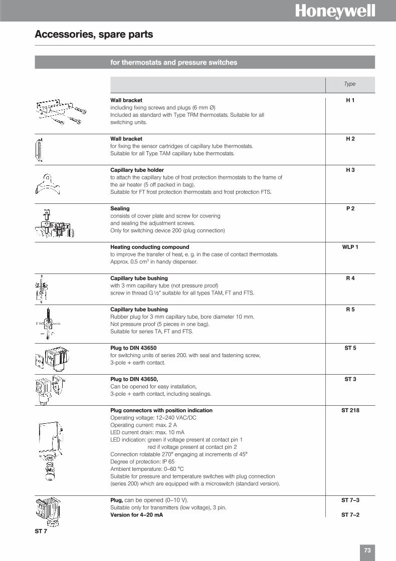
73
H
for thermostats and pressure switches
Accessories, spare parts
Wall bracket H 1including fixing screws and plugs (6 mm Ø)Included as standard with Type TRM thermostats. Suitable for allswitching units.
Wall bracket H 2for fixing the sensor cartridges of capillary tube thermostats.Suitable for all Type TAM capillary tube thermostats.
Capillary tube holder H 3to attach the capillary tube of frost protection thermostats to the frame ofthe air heater (5 off packed in bag).Suitable for FT frost protection thermostats and frost protection FTS.
Sealing P 2consists of cover plate and screw for coveringand sealing the adjustment screws.Only for switching device 200 (plug connection)
Heating conducting compound WLP 1to improve the transfer of heat, e. g. in the case of contact thermostats.Approx. 0.5 cm3 in handy dispenser.
Capillary tube bushing R 4with 3 mm capillary tube (not pressure proof)screw in thread G| suitable for all types TAM, FT and FTS.
Capillary tube bushing R 5Rubber plug for 3 mm capillary tube, bore diameter 10 mm.Not pressure proof (5 pieces in one bag).Suitable for series TA, FT and FTS.
Plug to DIN 43650 ST 5for switching units of series 200. with seal and fastening screw,3-pole + earth contact.
Plug to DIN 43650, ST 3Can be opened for easy installation,3-pole + earth contact, including sealings.
Plug connectors with position indication ST 218Operating voltage: 12–240 VAC/DCOperating current: max. 2 ALED current drain: max. 10 mALED indication: green if voltage present at contact pin 1
red if voltage present at contact pin 2Connection rotatable 270° engaging at increments of 45°Degree of protection: IP 65Ambient temperature: 0–60 °CSuitable for pressure and temperature switches with plug connection(series 200) which are equipped with a microswitch (standard version).
Plug, can be opened (0–10 V). ST 7–3Suitable only for transmitters (low voltage), 3 pin.Version for 4–20 mA ST 7–2
Type
ST 7
01331_Product Catalog_02 19.02.2002 9:30 Uhr Seite 73

74
H
Immersion tubes for thermostats and temperature transmitter
Type series ZT
for pressure proof installation for air ducts for exhaust pipes(up to 100 bar)R 1 R 2 R 3 R 10 R 20 R 6 R 7 R 8RN 1 RN 2 RN 10 RN 20
TAM…
TX…
TXB…
Temperature
Transmitter TP…
Type Depth of immersion Overall length Suitable forL1 (mm) L2 (mm)
Nickel-plated brass, G ||
R 1/Ms 135 151 TAM …R 2/Ms 220 236R 3/Ms 500 516
R 10/Ms 135 151 TX…/TPR 20/Ms 220 236
Stainless steel type (1.4571 + 1.4401) G ||
R 1/Nst 135 151 TAM …R 2/Nst 220 236
R 10/Nst 135 151 TX…/TPR 20/Nst 220 236
Nickel-plated brass type || NPT
RN 1/Ms 135 151 TAM …RN 2/Ms 220 236
RN 10/Ms 135 151 TX…/TPRN 20/Ms 220 236
Stainless steel type (1.4571 + 1.4401) || NPT
RN 1/Nst 135 151 TAM …RN 2/Nst 220 236
RN 10/Nst 135 151RN 20/Nst 220 236
Material: steel, chromated
R 6 135 mm TX …R 7 220 mm
Mounting flange for Pt 100-/Pt 1000 sensorSensor Ø = 5 mm R 8
Type Depth of immersion Suitable for
Immersion tubes with fixing flange for air ducts
only
toge
ther
with
ret
aini
ngsp
ring
FF 1
35
R 8 (example for Using of the immersion tubesmounting)
R 6 R 7
Immersion tubes G ||
Immersion tubes || NPT
01331_Product Catalog_02 19.02.2002 9:30 Uhr Seite 74
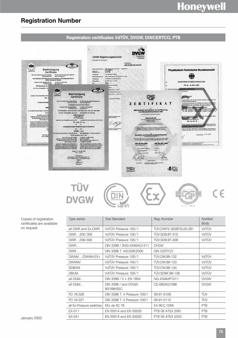
75
HRegistration Number
Registration certificates VdTÜV, DVGW, DINCERTCO, PTB
Type series Test Standard Reg.-Number NotifiedBody
all DWR and Ex-DWR VdTÜV Pressure 100/1 TÜV.DWFS (SDBFS).00-281 VdTÜV
DWR…205/305 VdTÜV Pressure 100/1 TÜV.SDB.97-310 VdTÜV
DWR…206/306 VdTÜV Pressure 100/1 TÜV.SDB.97-309 VdTÜV
DWR… DIN 3398 / 3NG-4346AQ1411 DVGW
DWR… DIN 3398 T. 43C028/2000 DIN CERTCO
DWAM…/DWAM-EX-i VdTÜV Pressure 100/1 TÜV.DW.99-132 VdTÜV
DWAMV VdTÜV Pressure 100/1 TÜV.DW.99-133 VdTÜV
SDBAM VdTÜV Pressure 100/1 TÜV.DW.99-134 VdTÜV
DBUM VdTÜV Pressure 100/1 TÜV.SDBF.99-136 VdTÜV
all DGM… DIN 3398 / 3 + EN 1854 NG-4346AP1011 DVGW
all DGM… DIN 3398 / and DVGW CE-085AQ1088 DVGW90/396/EEC
FD 16-326 DIN 3398 T. 4 Pressure 100/1 09-91-0109 TÜV
FD 16-327 DIN 3398 T. 4 Pressure 100/1 09-91-0110 TÜV
all Ex-Pressure switches EEx de IIC T6 EX-90.C.1059 PTB
EX-011 EN 50014 and EN 50020 PTB 00 ATEX 2081 PTB
EX-041 EN 50014 and EN 50020 PTB 00 ATEX 2043 PTB
TÜVDVGW e s
Copies of registration certificates are availableon request
January 2002
01331_Product Catalog_02 19.02.2002 9:30 Uhr Seite 75
s
Fema ControlsHoneywell AGBöblinger Strasse 17D-71 101 Schönaich Phone (49) 70 31 6 37-02Fax (49) 70 31 6 37-8 50E-Mail [email protected]://www.honeywell.de/fema
EN3B-0266GE51 R0202 Subject to change without notice. © 2001 Honeywell AG
L o c a l F e m a P a r t n e r s i n E u r o p e ,
M i d d l e E a s t , A f r i c a a n d A s i a P a c i f i c
LONM
AR
K®
and
the
LO
NW
OR
KS
® lo
go a
re r
egis
tere
d t
rad
emar
ks o
f the
Ech
elon
cor
por
atio
n.
AustriaFranz Schmachtl KGPummererstraße 364021 LinzPhone: (43) 7 32 76 46-0Fax: (43) 7 32 78 50 36
BelgiumERIKS N. V.Boombekelaan 32660 HobokenPhone: (32) 3-8 29 26 11Fax: (32) 3-8 28 39 59
BulgariaHoneywell EOOD14, Iskarsko ChausseePOB 791592 SofiaPhone: (359) 2 79 40 27Fax: (359) 2 79 40 90
Czech. RepublicHoneywell spol s r. o.Budejovicka 114021 Prague 4Phone: (420) 2 61 12 27 77Fax: (420) 2 61 12 26 91
DenmarkGRANZOW A/SEjby Industrievej 262600 GlostrupPhone: (45) 43 20 26 00Fax: (45) 43 20 26 99
FinlandHoneywell OYRuukintje 802320 Espoo 32Phone: (358) 93 48 01 01Fax: (358) 9 34 80 12 34
FranceBürkert & Contromatic FranceB.P. 2167220 Triembach au ValPhone: (33) 3.88.58.91.11Fax: (33) 3.88.57.20.08
GreeceHoneywell EPE313 Irakliou Ave./1-3 Viotias Str.Neon Iraklion – AthensPhone: (30) 12 84 80 49Fax: (30) 12 84 80 55
HungaryHoneywell Kft.Gogol u. 131133 BudapestPhone: (36) 14 51 43 00Fax: (36) 14 51 43 43
ItalyHoneywell S.p.A.Via Gobetti, 2b20063 Cernusco sul NaviglioPhone: (39) 02 92 14 61Fax: (39) 02 92 1468 88
NetherlandsERIKS B.V.Postbus 2801800 BK AlkmaarPhone: (31) 72 5 14 15 14Fax: (31) 72 5 15 56 45
NorwayBürkert-Contromatic A/SBox 2432026 SkjettenPhone: (47) 63-84 44 10Fax: (47) 63-84 44 55
PolandHoneywell sp. z.o.o.ul. Domaniewska 41(Budynek Mars)02-672 WarsawPhone: (48) 2 26 06 09 00Fax: (48) 2 26 06 09 01
PortugalHoneywell Portugal LdaEdificio Suecia IIAv do Forte Nr. 3 - Piso 32795 CarnaxidePhone: (351) 2 14 24 50 00Fax: (351) 2 14 24 50 99
RomaniaHoneywell Romania S.R.L.Blvd.Dacia No. 85Ap.9, sector 270256 BucharestPhone: (40) 12 11 00 76Fax: (40) 12 10 33 75
RussiaHoneywell Inc.4th floor, Administrative Bldg. of AO "Luzhniki" ManagementLuzhniki 24119048 MoscowPhone: (7) 09 57 96 98 00/01Fax: (7) 09 57 96 98 93/92
Slovak RepublicHoneywell LtdMlynske Nivy 73PO Box 7582007 Bratislava 27Phone: (421) 7 58 24 74 00/425Fax: (421) 7 58 24 74 15
SpainHoneywell S.A.Josefa Valcárcel, 2428027 MadridPhone: (34) 9 13 13 61 00Fax: (34) 9 13 13 61 27
SwedenBürkert-Contromatic ABSkeppsbron 13 B21120 MalmoePhone: (46) 40 6 64 51 00Fax: (46) 40 6 64 51 01
SwitzerlandTRI-MATIC AGBösch 826331 HünenbergPhone: (41) 41 7 80 22 22Fax: (41) 41 7 80 03 60
TurkeyHoneywell Otomasyon Ve KontrolSistemleri San. Ve Tic. A.S. Cayiryolu Sok. (Halyolu)Ucgen Plaza No: 7, Kat 5-6-7Icerenkoy 81120 / Istanbul Phone: (90) 21 64 64 47 74Fax: (90) 21 64 64 47 94
UkraineHoneywellZhelyabova 8/403680 KievPhone: (38) 04 42 41 91 95Fax: (38) 2 41 91 96
United KingdomBürkert Contromatic Ltd.Fluid Control CentreBrimscombe Port, Bus. ParkBrimscombe Stroud,Glos GL5 2QFPhone: (44) 14 53 73 13 53Fax: (44) 14 53 73 13 43
Middle East HeadquartersHoneywell Middle East Ltd. Khalifa St.Sheikh Faisal BuildingAbu Dhabi, United Arab EmiratesPhone: (971) 26 27 25 33Fax: (971) 26 26 95 39
Distributors & Africa HeadquartersHoneywell S.p.A.International OperationsVia Gobetti, 2b20063 Cernusco sul NaviglioPhone: (39) 2 92 14 61Fax: (39) 2 92 14 68 88
South AfricaWIKA INSTRUMENTS (Pty.) Ltd.P.O. Box 75225 Gardenview 2047Phone: (27) 11-621-0000Fax: (27) 11-621-0049
Asia Pacific HeadquartersHoneywell Pte Ltd.Honeywell Building17 Changi Business Park Central 1Singapore 486073Republic of SingaporePhone: (65) 35 50 28 28Fax: (65) 4 45 30 33
H
f
01331_Product Catalog_02 19.02.2002 9:30 Uhr Seite 76