Embed Size (px)
Citation preview
—PRODUC T C ATALOG 2018
Power semiconductors

— ABB’s success story in power electronics began more than 100 years ago with the production of mercury-arc rectifiers in Switzerland. Over the past 60 years, ABB has played a pivotal part in the development of power semiconductors and their applications.
ABB is a leading supplier of power semiconductors with production facilities in Lenzburg, Switzerland, and Prague, Czech Republic, as well as a research laboratory for wide bandgap semiconductors in Baden-Dättwil, Switzerland.
Exceeding quality requirements, guaranteeing reliability expectations and perpetual pioneering are our distinctions.
This product catalog provides an overview of ABB’s full range of power semiconductors.
Additionally, a compilation of broad background information on our portfolio can be found in our product brochure.
For more information please contact us or visit www.abb.com/semiconductors
TA B L E O F CO NTENTS
— Table of contents
Introduction
ApplicationsSEMIS – Semiconductor simulation toolProduct outlook
IGBT dies and modules
IGBT and diode diesMedium-power IGBT modulesHigh-power IGBT and diode modules
Diodes, thyristors, IGCTs and GTO press-packs
DiodesThyristorsIntegrated gate-commutated thyristors (IGCTs)Gate turn-off thyristors (GTOs)Silicon surge voltage suppressors
Test systems
Further information
CertificatesREACH DeclarationSymbolsDocumentationPart numbering structurePerpetual innovation
Worldwide distributors
004 – 005006 – 007008 – 009
010 – 011012 – 013014 – 023
024 – 033034 – 041 042 – 045 046 – 047 048 – 049
050 – 051
052 – 053054 – 054055 – 055056 – 057058 – 061062 – 063
064 – 065

1
4
4
—Applications
ABB’s power semiconductors are key components in a variety of demanding appli-cations in markets like power transmission & distribution, industrial, transportation and renewable energy. Customers rely on ABB’s high quality power semiconductor products and use them in applications in power ranges from 50 kW to 10 GW.
1
PRO D U C T C ATA LO G P OW ER SEM I CO N D U C TO R S

1
1 3
4 4 4
4
5
1
Power transmission and distribution (HVDC, FACTS, STATCOM and others)Industry (medium and low-voltage drives, soft starters, UPSs, high-power rectifiers, excitation systems and others)
Transportation (main and auxiliary drives, trackside power supply)Renewable energy (converters for pumped hydro, wind turbines and solar)
1
2
3
4
2
2
A PPL I C ATI O NS
6
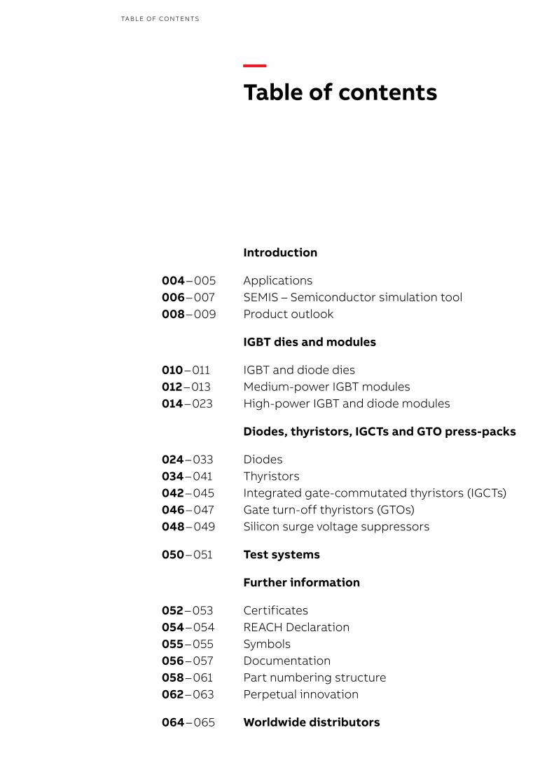
Simulation results are presented in graphical and numerical form. With the steady-state analysis, temperature development is evaluated thus en-abling the identification of most influencing com-ponents. A flexible variation of semiconductor devices enables optimization of the cost / benefit ratio. Output graphs indicate current, voltage,
power and temperatures according to the se-lected topology and settings.
The numerical results listed inform about power losses and junction temperatures of all semicon-ductor devices according to the load and cus-tomer defined thermal resistances of cooling.
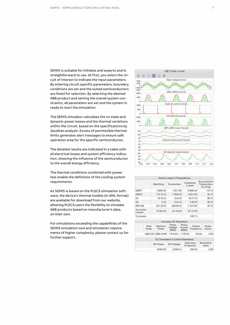
—SEMIS Semiconductor simulation tool
ABB’s semiconductor simulation tool SEMIS is a sophisticated web application to evaluate the optimal choice of high power semiconductors in regards of thermal losses and device utilization. By selection of topology and definition of relevant circuit parameters, SEMIS performs an analysis of various system dependencies and evaluates thermal conditions enabling verification of semiconductors device capabilities.
PRO D U C T C ATA LO G P OW ER SEM I CO N D U C TO R S
7
SEMIS is suitable for initiates and experts and is straightforward to use. At first, you select the cir-cuit of interest to indicate the input parameters. By entering circuit specific parameters, boundary conditions are set and the suited semiconductors are listed for selection. By selecting the desired ABB product and setting the overall system con-straints, all parameters are set and the system is ready to start the simulation.
The SEMIS simulator calculates the on state and dynamic power losses and the thermal variations within the circuit, based on the specifications by Jacobian analysis. Excess of permissible thermal limits generates alert messages to ensure safe operation area for the specific semiconductor.
The detailed results are indicated in a table with all electrical losses and system efficiency indica-tion, showing the influence of the semiconductor to the overall energy efficiency.
The thermal conditions combined with power loss enable the definition of the cooling system requirements.
As SEMIS is based on the PLECS simulation soft-ware, the device’s thermal models (in XML format) are available for download from our website, allowing PLECS users the flexibility to simulate ABB products based on manufacturer’s data, on their own.
For simulations exceeding the capabilities of the SEMIS simulation tool and simulation require-ments of higher complexity, please contact us for further support.
SEM IS - SEM I CO N D U C TO R SI M U L ATI O N TO O L

8
ABB Semiconductors’ vast range of power semiconductors for industrial, power genera-tion & distribution, traction and renewable energy markets will be expanded soon with the following new products:
6500 V 900 A HiPak with 150 °C operation temperatureThe improved SPT++ technology boosts the rating of the 6500 V IGBT from 750 to 900 A. In addition it allows the IGBT module to be operated up to Tvj(op) = 150 °C with unrivaled robustness. For improved performance in regenerative mode we have increased the diode area by 20 %. This opens the potential to choose a smaller module size or eliminate parallel connection of modules.
—Product outlook
Innovation and quality are key for success. It is our mission to drive innovation in power semiconductor technology together with our customers and to add value through best performance and quality. We strive to be the best and most forward-looking performer in our markets when it comes to reliability.
PRO D U C T C ATA LO G P OW ER SEM I CO N D U C TO R S
Availability Rating Configuration VCEsat (V)typ. 150 °C
VF (V)typ. 150 °C
Housing
HiPak2 G Samples Q2/18 6500 V 900 A single IGBT 3.9 3.2 G (10.2 kV ISOL)
HiPak1 J Samples Q3/18 6500 V 600 A single IGBT 3.9 3.2 J (10.2 kV ISOL)
—Ratings of 6500 V SPT++ HiPak
9
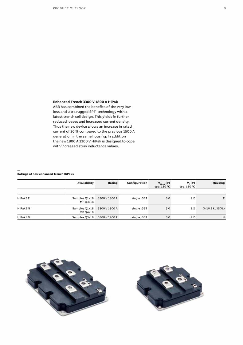
Enhanced Trench 3300 V 1800 A HiPakABB has combined the benefits of the very low loss and ultra rugged SPT+ technology with a latest trench cell design. This yields in further reduced losses and increased current density. Thus the new device allows an increase in rated current of 20 % compared to the previous 1500 A generation in the same housing. In addition the new 1800 A 3300 V HiPak is designed to cope with increased stray inductance values.
PR O D U C T O U TLO O K
Availability Rating Configuration VCEsat (V)typ. 150 °C
VF (V)typ. 150 °C
Housing
HiPak2 E Samples Q1/18MP Q3/18
3300 V 1800 A single IGBT 3.0 2.2 E
HiPak2 G Samples Q1/18MP Q4/18
3300 V 1800 A single IGBT 3.0 2.2 G (10.2 kV ISOL)
HiPak1 N Samples Q3/18 3300 V 1200 A single IGBT 3.0 2.2 N
—Ratings of new enhanced Trench HiPaks

10
—IGBT and diode dies
When looking for chipsets featuring highest switching performance, ruggedness and reliability, ABB’s IGBT chips with accompanying diodes are certainly the preferred choice.
Part number Type Size A x B mm
Thicknessμm
VPRM (V) IF (A) VF (V)typ. 125 °C
Max. dies per wafer (W)or tray (T)
1.2 kV
5SLY 76E12005SLY 86E1200 SPT+ 6.3 x 6.3 350 1200 50 1.85 361 (W)
5SLY 76F12005SLY 86F1200 SPT+ 7.4 x 7.4 350 1200 75 1.85 257 (W)
5SLY 76G12005SLY 86G1200 SPT+ 8.4 x 8.4 350 1200 100 1.85 198 (W)
5SLY 76J12005SLY 86J1200 SPT+ 10.0 x 10.0 350 1200 150 1.85 137 (W)
PRO D U C T C ATA LO G P OW ER SEM I CO N D U C TO R S
—Diode dies
ABB Semiconductors’ SPT (Soft Punch Through) chipsets and their improved versions with lower losses (SPT+ and SPT++) are available at 1200 V and 1700 V. They feature highest output power per rated ampere due to a moderate chip shrinkage and thus larger die area compared to others.
Typical applications for 1200 V are power con-verters for industrial drives, solar energy, battery backup systems (UPS) and electrical vehicles. Applications for 1700 V also include industrial power conversion & drives, wind turbines and traction converters.
ABB’s 1700 V SPT++ chipset is the world’s first 1700 V chipset that offers an operational junction temperature of up to 175 °C. This allows the module designer to increase the power density of the IGBT modules significantly.
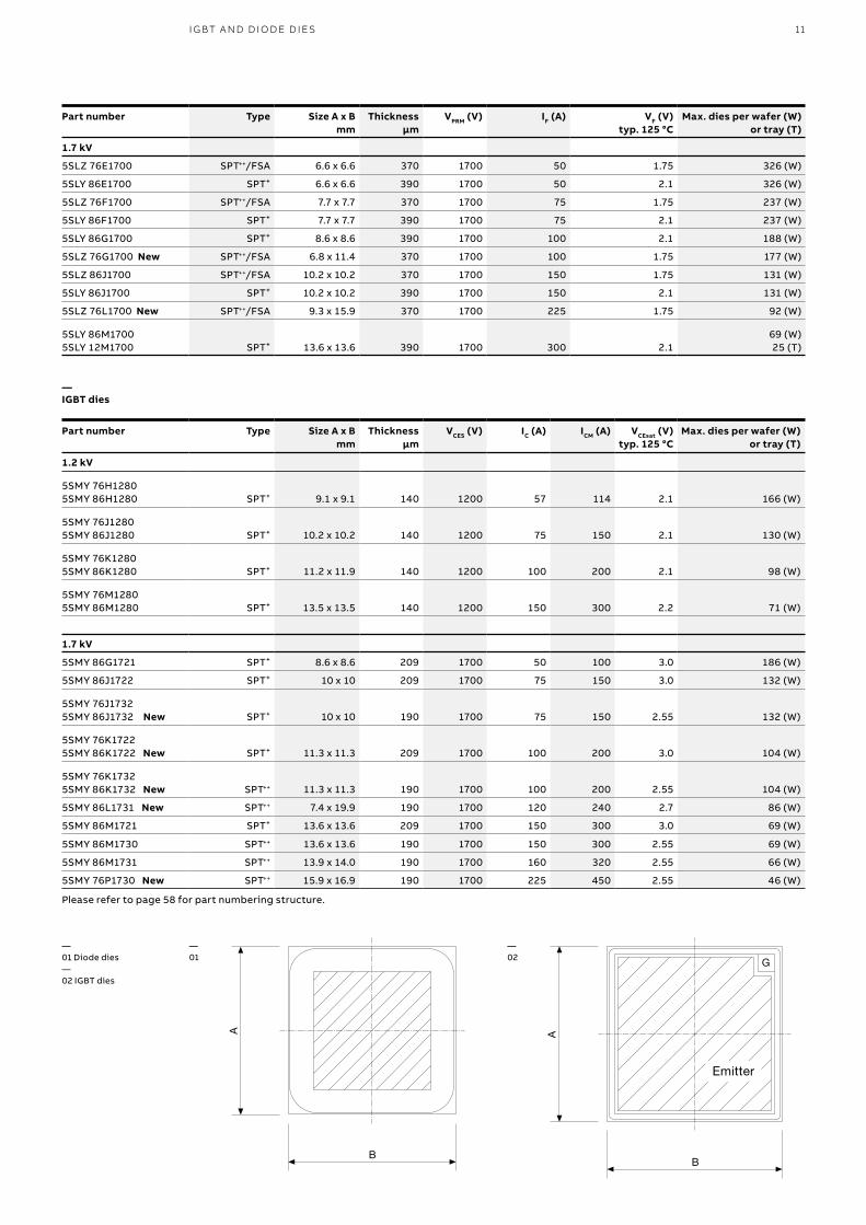
11
Part number Type Size A x B mm
Thicknessμm
VPRM (V) IF (A) VF (V)typ. 125 °C
Max. dies per wafer (W)or tray (T)
1.7 kV
5SLZ 76E1700 SPT++/FSA 6.6 x 6.6 370 1700 50 1.75 326 (W)
5SLY 86E1700 SPT+ 6.6 x 6.6 390 1700 50 2.1 326 (W)
5SLZ 76F1700 SPT++/FSA 7.7 x 7.7 370 1700 75 1.75 237 (W)
5SLY 86F1700 SPT+ 7.7 x 7.7 390 1700 75 2.1 237 (W)
5SLY 86G1700 SPT+ 8.6 x 8.6 390 1700 100 2.1 188 (W)
5SLZ 76G1700 New SPT++/FSA 6.8 x 11.4 370 1700 100 1.75 177 (W)
5SLZ 86J1700 SPT++/FSA 10.2 x 10.2 370 1700 150 1.75 131 (W)
5SLY 86J1700 SPT+ 10.2 x 10.2 390 1700 150 2.1 131 (W)
5SLZ 76L1700 New SPT++/FSA 9.3 x 15.9 370 1700 225 1.75 92 (W)
5SLY 86M17005SLY 12M1700 SPT+ 13.6 x 13.6 390 1700 300 2.1
69 (W)25 (T)
I G BT A N D D I O D E D I E S
Part number Type Size A x B mm
Thicknessμm
VCES (V) IC (A) ICM (A) VCEsat (V)typ. 125 °C
Max. dies per wafer (W)or tray (T)
1.2 kV
5SMY 76H12805SMY 86H1280 SPT+ 9.1 x 9.1 140 1200 57 114 2.1 166 (W)
5SMY 76J12805SMY 86J1280 SPT+ 10.2 x 10.2 140 1200 75 150 2.1 130 (W)
5SMY 76K12805SMY 86K1280 SPT+ 11.2 x 11.9 140 1200 100 200 2.1 98 (W)
5SMY 76M12805SMY 86M1280 SPT+ 13.5 x 13.5 140 1200 150 300 2.2 71 (W)
1.7 kV
5SMY 86G1721 SPT+ 8.6 x 8.6 209 1700 50 100 3.0 186 (W)
5SMY 86J1722 SPT+ 10 x 10 209 1700 75 150 3.0 132 (W)
5SMY 76J17325SMY 86J1732 New SPT+ 10 x 10 190 1700 75 150 2.55 132 (W)
5SMY 76K17225SMY 86K1722 New SPT+ 11.3 x 11.3 209 1700 100 200 3.0 104 (W)
5SMY 76K1732 5SMY 86K1732 New SPT++ 11.3 x 11.3 190 1700 100 200 2.55 104 (W)
5SMY 86L1731 New SPT++ 7.4 x 19.9 190 1700 120 240 2.7 86 (W)
5SMY 86M1721 SPT+ 13.6 x 13.6 209 1700 150 300 3.0 69 (W)
5SMY 86M1730 SPT++ 13.6 x 13.6 190 1700 150 300 2.55 69 (W)
5SMY 86M1731 SPT++ 13.9 x 14.0 190 1700 160 320 2.55 66 (W)
5SMY 76P1730 New SPT++ 15.9 x 16.9 190 1700 225 450 2.55 46 (W)
Please refer to page 58 for part numbering structure.
—IGBT dies
—01 Diode dies —02 IGBT dies
—02
—01

12
—Medium-power IGBT modules
ABB enhances its successful IGBT module range into the medium-power segment. Starting with the 62Pak and the LoPak1, ABB brings the proven high quality and reliability of the HiPak modules to the medium-power IGBT segment
Part numberTvj (operational) up to 175 °C
Voltage VCES (V) Current IC (A) Configuration * VCEsat (V) VF (V) Housing
1.7 kV
5SNG 0150Q170300 1700 2 x 150 (5) - Phase leg IGBT 2.55 1.75 Q
5SNG 0200Q170300 1700 2 x 200 (5) - Phase leg IGBT 2.55 1.75 Q
5SNG 0300Q170300 1700 2 x 300 (5) - Phase leg IGBT 2.55 1.75 Q
Please refer to page 59 for part numbering structure.* Configurations on page 20
PRO D U C T C ATA LO G P OW ER SEM I CO N D U C TO R S
ABB’s 62Pak modules have an advanced packaging technology that leverages the performance of the latest silicon technology:• 1700 V SPT++ fast switching IGBT / diode chipset
with lowest switching losses• Full 175 °C operation temperature with full
square SOA• Best-in-class temperature cycling performance
of bond-wire chip connection• Standard package allowing drop-in replacement
8888
DDDD
CCCC
BBBB
AAAA
77776666
UUUUNNNNLLLLEEEESSSSSSSS OOOOTTTTHHHHEEEERRRRWWWWIIIISSSSEEEE SSSSPPPPEEEECCCCIIIIFFFFIIIIEEEEDDDD::::DDDDIIIIMMMMEEEENNNNSSSSIIIIOOOONNNNSSSS AAAARRRREEEE IIIINNNN MMMMIIIILLLLLLLLIIIIMMMMEEEETTTTEEEERRRRSSSS
1111::::1111
5555
AAAA4444
444433332222
BBBB
1111
AAAA
2222
CCCC
DDDD
3333
IIIIFFFF IIIINNNN DDDDOOOOUUUUBBBBTTTT AAAASSSSKKKKFFFF
EEEE
1111
00000000 TTTTIIIITTTTLLLLEEEE
INTEGRATED MICROELECTRONICS INC.
EEEE
FFFF
CCCCOOOONNNNFFFFIIIIDDDDEEEENNNNTTTTIIIIAAAALLLL IIIINNNNFFFFOOOORRRRMMMMAAAATTTTIIIIOOOONNNN CCCCooooppppyyyyrrrriiiigggghhhhtttt ((((CCCC)))) 2222000000007777 IIIIMMMMIIII AAAAllllllll rrrriiiigggghhhhtttt rrrreeeesssseeeerrrrvvvveeeedddd
WWWWhhhheeeennnn pppprrrriiiinnnntttteeeedddd,,,, tttthhhhiiiissss ddddooooccccuuuummmmeeeennnntttt iiiissss uuuunnnnccccoooonnnnttttrrrroooolllllllleeeedddd uuuunnnnlllleeeessssssss pppprrrrooooppppeeeerrrrttttyyyy iiiiddddeeeennnnttttiiiiffffiiiieeeedddd aaaassss ccccoooonnnnttttrrrroooolllllllleeeedddd
DDDDAAAATTTTEEEEAAAAPPPPPPPPRRRROOOOVVVVAAAALLLLSSSS
RRRREEEEFFFFEEEERRRREEEENNNNCCCCEEEE NNNNOOOO....
MMMMOOOODDDDEEEELLLL////PPPPAAAARRRRTTTT NNNNAAAAMMMMEEEE
TTTT HHHH IIIIRRRR DDDD AAAA NNNN GGGG LLLL EEEE PPPP RRRR OOOOJJJJ EEEE CCCC TTTT IIIIOOOO NNNN
IIIINNNNTTTTEEEERRRRNNNNAAAALLLL DDDDRRRRAAAAWWWWIIIINNNNGGGG RRRREEEEFFFF....
....XXXX`̀̀̀0000 ....22225555
CCCCUUUUSSSSTTTTOOOOMMMMEEEERRRR
4444
VVVVEEEERRRR IIIIFFFFIIIIEEEEDDDD BBBBYYYY ::::
CCCCHHHHEEEECCCCKKKKEEEEDDDD BBBBYYYY ::::
....XXXXXXXXXXXX`̀̀̀0000.... 00005555
RRRREEEEFFFF.... RRRREEEEVVVV....
5555
....XXXXXXXX`̀̀̀0000 ....1111
6666
AAAANNNNGGGGLLLLEEEE`̀̀̀5555~~~~
SSSSIIIIZZZZEEEE
DDDDRRRRAAAAWWWWIIIINNNNGGGG NNNNOOOO....
7777
SSSSCCCCAAAALLLLEEEE DDDDOOOO NNNNOOOOTTTT SSSSCCCCAAAALLLLEEEE HHHHAAAARRRRDDDD CCCCOOOOPPPPYYYY
8888
AAAAPPPPPPPPRRRROOOOVVVVEEEEDDDD BBBBYYYY ::::
#### 1111 0000 3333 TTTT RRRR AAAA DDDD EEEE AAAA VVVVEEEE .... ,,,, CCCC OOOO RRRR .... TTTT EEEE CCCC HHHH NNNN OOOO LLLL OOOO GGGG YYYY AAAA VVVV EEEE .... ,,,, PPPP HHHH AAAA SSSS EEEE 4444 ,,,, LLLL TTTT IIII ,,,, BBBB IIII NNNN AAAA NNNN ,,,, LLLL AAAA GGGG UUUU NNNN AAAA
SSSSHHHHEEEEEEEETTTT
RRRREEEEVVVV....
DDDDRRRRAAAAWWWWNNNN BBBBYYYY ::::
FFFFCCCC
FFFFAAAABBBBRRRRIIIICCCCAAAATTTTIIIIOOOONNNN ((((PPPPRRRROOOOTTTTOOOO----TTTTYYYYPPPPEEEE RRRREEEEFFFFEEEERRRREEEENNNNCCCCEEEE))))
FFFFAAAABBBBRRRRIIIICCCCAAAATTTTIIIIOOOONNNN ((((PPPPRRRROOOOTTTTOOOO----TTTTYYYYOOOOEEEE////QQQQUUUUAAAALLLLIIIIFFFFIIIICCCCAAAATTTTIIIIOOOONNNN))))
IIIINNNNIIIITTTTIIIIAAAALLLL ((((CCCCOOOONNNNCCCCEEEEPPPPTTTT))))
RRRREEEEVVVVIIIISSSSIIIIOOOONNNN HHHHIIIISSSSTTTTOOOORRRRYYYY
EEEEFFFFFFFFEEEECCCCTTTTIIIIVVVVIIIITTTTYYYY DDDDAAAATTTTEEEEDDDDEEEESSSSCCCCRRRRIIIIPPPPTTTTIIIIOOOONNNN////PPPPUUUURRRRPPPPOOOOSSSSEEEERRRREEEEVVVV....
00000000
----00001111
----00002222
AAAAFFFF
DDDDJJJJ
IIIINNNNIIIITTTTIIIIAAAALLLL
-------- ---- -------- ---- ----------------
-------- ---- -------- ---- ----------------
-------- ---- -------- ---- ----------------
FFFFOOOORRRRMMMM NNNNOOOO.... EEEENNNNGGGG000000001111----MMMMDDDD ((((00002222////00008888))))FFFFoooorrrrmmmm NNNNoooo.... 444422223333----000000000000----000000004444----00001111 RRRReeeevvvv.... BBBB
DANDY N JADUCANA
ARNOLD SANCHEZ
DANDY JADUCANA
62Pak PACKAGE OUTLINE DRAWING
30.6
29`.
30
23`.
30
30.8
`.50
6 `.3
0
20
mounting depth max. 10
61.4
`.30
48`.
20
2715
106.4 `.30
93 `.20
28 28
14 `.20 14 `.20 14 `.20
13.2
`.20
6.5-
.30
+.10
13.2 `.20
M6
6.4 `
.10
MALE PLUG 46244-A2.8-0.5-MS
mounting depth min. 7
6
common tolerance zone
ISOMETRIC VIEW
20.0
`.20
PO0032700
B
A
C
i .3 B
i .3 A
f .75 C 3X
j n1.5 AB 4X
j n.8 AB 3x
c 1.40
FOR QUALIFICATION REFERENCE
00
7.75
1 / 1
62Pak Power Module
—Q
— Dimensions in mm

13
Part numberTvj (operational) up to 175 °C
Voltage VCES (V) Current IC (A) Configuration * VCEsat (V) VF (V) Housing
1.7 kV
5SNG 0225R170300 New 1700 2 x 225 (5) - Phase leg IGBT 2.55 1.75 R
5SNG 0300R170300 New 1700 2 x 300 (5) - Phase leg IGBT 2.55 1.75 R
5SNG 0450R170300 New 1700 2 x 450 (5) - Phase leg IGBT 2.55 1.75 R
Please refer to page 59 for part numbering structure.* Configurations on page 20
M ED I U M - P OW ER I G BT M O D U L E S
ABB's LoPak is 100 % mechanically compatiblewith the Econo-type dual IGBT modules. It sets a new benchmark with full switching performance up to 175 °C. It is specifically designed for excellent internal current sharing, offering optimalthermal utilization and increased robustness.Thus customers can expect larger safety margin and increased lifetime. Typical applications include:• Wind power converters• Variable speed drives• Power supplies• Power quality• UPS• Renewable energies
—R
— Dimensions in mm

14
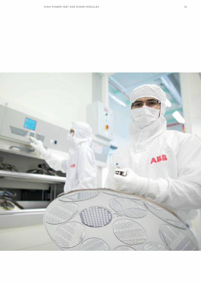
—High-power IGBT and diode modules
ABB offers two categories of high-power IGBT and diode modules: Insulated and press-pack modules.
PRO D U C T C ATA LO G P OW ER SEM I CO N D U C TO R S
Insulated modules consist of the new innovative, low inductive phase leg LinPak and the well-established HiPak lineup with more than 15 years of successful track record.
Press-pack modules are a range of pressure contact IGBT modules also known as StakPak. StakPaks are ABB’s flagship with record power ratings up to 4500 V and 3000 A.
ABB’s high-power IGBT and diode module families are:• LinPak IGBT modules page 16• HiPak IGBT and diode modules page 18• StakPak IGBT press-pack modules page 22
15H I G H - P OW ER I G BT A N D D I O D E M O D U L E S

16
—LinPak IGBT modules
The LinPak is a new innovative solution for all power conversion applications. It enables the design of converters with lowest overall inductance, thus fast low switching loss chipsets can be used for the first time also in high-current applications.
PRO D U C T C ATA LO G P OW ER SEM I CO N D U C TO R S
These applications include amongst others traction, converters for wind turbines or other renewables, industrial drives, as well as power electronics for FACTS applications. In addition, the LinPak allows very easy parallel connection,thus the current rating of the inverters can be scaled up with just one article number.
This makes the supply chain and initial device design-in efforts significantly more efficient.
ABB’s LinPak modules feature lowest switching losses and excellent robustness thanks to its low inductance.

17
—LinPak IGBT modules
The LinPak is a new innovative solution for all power conversion applications. It enables the design of converters with lowest overall inductance, thus fast low switching loss chipsets can be used for the first time also in high-current applications.
Part numberTvj (operational) up to 175 °C
Voltage VCES (V) Current IC (A) Configuration * VCEsat (V)typ. 125 °C
VF (V)typ. 125 °C
Housing
1.7 kV
5SNG 1000X170300 1700 2 x 1000 (5) – Phase leg IGBT 2.55 1.75 X
5SNG 0450X330300 New 3300 2 x 450 (5) – Phase leg IGBT 3.1 2.25 X
Please refer to page 59 for part numbering structure.* Configurations on page 20
L I N PA K I G BT M O D U L E S
—X
— Dimensions in mm
2015
ISO 2768-mKUnless otherwise specified general tolerance class according to:
All dimensions in millimeters
We reserve all rights in this document and in the information contained therein.Reproduction, use or disclosure to third parties without express authority is strictly forbidden.
ABB Switzerland Ltd c Produced using Inventor SemiconductorsABB Switzerland Ltd
Checked by:
Approved by:Replaces:
Revised by:Prepared by:
Filename
Format
Document No.
Article No. / Description No. of Sh.Sheet
Revision
Scale
-Outline Drawing
LinPak LV 5SZL 0524 02
1:1 A2 1 1
058172.idw
20.01.2016 CHDOTRU119.07.2016 CHDOTRU124.08.201624.08.2016
CHFAFIS1CHANBER1
29.5
38
46
82
86
100
6.5
4x
18
16.5
1813
5
53.5
5
29.5
127
140
4x M3screwing depthmax. 6
6x M3screwing depthmax. 6
6x M8screwing depthmax. 16
14.5
4
8.5 14.527.5118
18
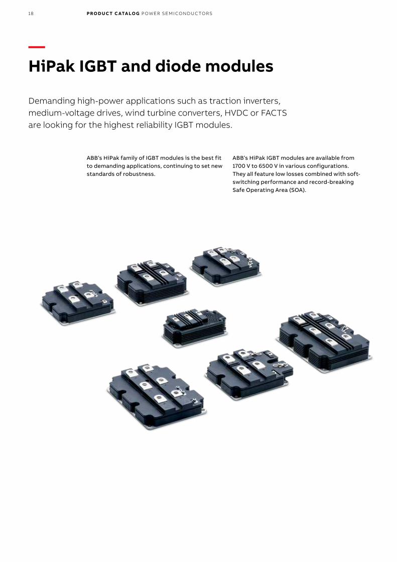
—HiPak IGBT and diode modules
Demanding high-power applications such as traction inverters, medium-voltage drives, wind turbine converters, HVDC or FACTS are looking for the highest reliability IGBT modules.
PRO D U C T C ATA LO G P OW ER SEM I CO N D U C TO R S
ABB’s HiPak family of IGBT modules is the best fit to demanding applications, continuing to set new standards of robustness.
ABB’s HiPak IGBT modules are available from 1700 V to 6500 V in various configurations. They all feature low losses combined with soft-switching performance and record-breaking Safe Operating Area (SOA).

19
Part numberTvj (operational) up to 125 °C
Voltage VCES (V) Current IC (A) Configuration VCEsat (V)typ. 125 °C
VF (V)typ. 125 °C
Housing
1.7 kV
5SND 0800M170100 1700 2 x 800 (3) – Dual IGBT 2.6 1.7 M
5SNE 0800M170100 1700 800 (2) – Chopper 2.6 1.7 M
5SNA 1600N170100 1700 1600 (1) – Single IGBT 2.6 1.7 N1
5SNA 1800E170100 1700 1800 (1) – Single IGBT 2.6 1.7 E
5SNA 2400E170100 * 1700 2400 (1) – Single IGBT 2.6 1.7 E
3.3 kV
5SNE 0800E330100 3300 800 (2) – Chopper 3.8 2.35 E
5SNA 0800N330100 3300 800 (1) – Single IGBT 3.8 2.35 N1
5SLD 1200J330100 3300 2 x 1200 (4) – Dual Diode – 2.35 J
5SNA 1200E330100 3300 1200 (1) – Single IGBT 3.8 2.35 E
5SNA 1200G330100 3300 1200 (1) – Single IGBT 3.85 2.35 G
Tvj (operational) up to 150 °C
1.7 kV
5SNA 1600N170300 New 1700 1600 (1) – Single IGBT 2.4 1.67 N
5SNA 2400N170300 New 1700 2400 (1) – Single IGBT 3.0 1.95 N
5SNA 2400E170305 1700 2400 (1) – Single IGBT 2.4 1.67 E
5SNA 3600E170300 1700 3600 (1) – Single IGBT 3.0 1.95 E
5SNE 1600E170300 New 1700 1600 (2) – Chopper 2.4 1.67 E
5SNE 2400E170300 New 1700 2400 (2) – Chopper 3.0 1.95 E
5SLA 3600E170300 1700 3600 (6) – Single Diode – 1.95 E
2.5 kV
5SNA 1500E250300 * 2500 1500 (1) – Single IGBT 2.5 2.0 E
3.3 kV
5SNG 0250P330305 3300 2 x 250 (5) – Phase leg IGBT 3.1 2.25 P
5SLG 0500P330300 3300 2 x 500 (7) – Phase leg Diode – 2.25 P
5SND 0500N330300 3300 2 x 500 (3) – Dual IGBT 3.1 2.25 N2
5SLD 1000N330300 3300 2 x 1000 (4) – Dual Diode – 2.25 N1
5SNA 1000N330300 3300 1000 (1) – Single IGBT 3.1 2.25 N1
5SNE 1000E330300 3300 1000 (2) – Chopper 3.1 2.25 E
5SNA 1500E330305 3300 1500 (1) – Single IGBT 3.1 2.25 E
4.5 kV
5SNG 0150P450300 4500 2 x 150 (5) – Phase leg IGBT 3.5 3.45 P
5SLG 0600P450300 4500 2 x 600 (7) – Phase leg Diode – 3.5 P
5SLD 0650J450300 4500 2 x 650 (4) – Dual Diode – 3.4 J
5SNA 0650J450300 4500 650 (1) – Single IGBT 3.7 3.4 J
5SNA 0800J450300 4500 800 (1) – Single IGBT 3.55 3.5 J
5SNE 0800G450300 4500 800 (2) – Chopper 3.55 3.5 G
5SLD 1200J450350 4500 2 x 1200 (4) – Dual Diode – 3.5 J
5SNA 1200G450300 4500 1200 (1) – Single IGBT 3.55 3.5 G
5SNA 1200G450350 4500 1200 (1) – Single IGBT 3.55 3.5 G
6.5 kV
5SNA 0400J650100 6500 400 (1) – Single IGBT 5.4 3.4 J
5SNA 0500J650300 6500 500 (1) – Single IGBT 3.9 3.4 J
5SLD 0600J650100 6500 2 x 600 (4) – Dual Diode – 3.4 J
5SNA 0600G650100 6500 600 (1) – Single IGBT 5.4 3.4 G
5SNA 0750G650300 6500 750 (1) – Single IGBT 3.9 3.4 G
Please refer to page 59 for part numbering structure.* not for new designs
H I PA K I G BT A N D D I O D E M O D U L E S

20 PRO D U C T C ATA LO G P OW ER SEM I CO N D U C TO R S
—Configurations
—01
—06
—07
—02
—03
—04
—05
«fin
e»«m
ediu
m»
Geo
met
rical
tole
ranc
esLi
near
- and
ang
ular
dim
.HZ
N 40
1 63
8;
DIN
716
8 T.
1;
ISO
276
8DI
N 71
68 T
.2:..
.«c
oars
e»R
epro
duct
ion,
use
or d
iscl
osur
e to
third
par
ties
with
out e
xpre
ss a
utho
rity
is s
trict
ly fo
rbid
den.
We
rese
rve
all r
ight
s in
this
doc
umen
t and
in th
e in
form
atio
n co
ntai
ned
ther
ein.
Roug
hnes
s-sy
mbo
ls ac
cord
ing
to G
ZN 0
2000
7eq
uiva
lent
to D
IN IS
O 1
302
Gen
eral
tole
ranc
e cla
ss fo
r mac
hine
d pa
rts.
Prod
uced
usi
ng In
vent
orA
BB
Sw
itzer
land
Ltd
c
All d
imen
sions
in m
illim
eter
s
2004
X
SemiconductorsABB Switzerland Ltd
Checked by:
ABB
Approved by:Replaces:
Revised by:Prepared by:
Filename
Format
Document No.
Article No. / Description No. of Sh.Sheet
Revision
Scale
Outline DrawingMod IGBT E/E+HiPak2013 5SZL 0423 01
1:1 A4 1 1
051606.idw
11.09.2013 SEMDOTR
57`0.1171`0.15
40`
0.2
124`
0.1
1 2 3 4
8 7 6 5
20
3.5 deep
3* M4
7n`0.1
8* 20.25`0.2
41.25`0.2
79.4`0.2
6* M8
5`
0.2
38- 01+
13`0.2
61.5`0.361.5`0.3
29.5`0.5
40`
0.2
5.2`
0.2
28`0.5
screwing depthmax. 8
screwing depthmax. 16
15`
0.2
140`
0.5
190`0.5
«fin
e»«m
ediu
m»
Geo
met
rical
tole
ranc
esLi
near
- and
ang
ular
dim
.HZ
N 40
1 63
8;
DIN
716
8 T.
1;
ISO
276
8DI
N 71
68 T
.2:..
.«c
oars
e»R
epro
duct
ion,
use
or d
iscl
osur
e to
third
par
ties
with
out e
xpre
ss a
utho
rity
is s
trict
ly fo
rbid
den.
We
rese
rve
all r
ight
s in
this
doc
umen
t and
in th
e in
form
atio
n co
ntai
ned
ther
ein.
Roug
hnes
s-sy
mbo
ls ac
cord
ing
to G
ZN 0
2000
7eq
uiva
lent
to D
IN IS
O 1
302
Gen
eral
tole
ranc
e cla
ss fo
r mac
hine
d pa
rts.
Prod
uced
usi
ng In
vent
orA
BB S
witz
erla
nd L
tdc
All d
imen
sions
in m
illim
eter
s
2004
X
SemiconductorsABB Switzerland Ltd
Checked by:
Approved by:Replaces:
Revised by:Prepared by:
Filename
Format
Document No.
Article No. / Description No. of Sh.Sheet
Revision
Scale
Outline DrawingMod IGBT GHiPak2014 5SZL 0471 02
1:2 A4 1 1
053916.idw
28.08.2014 CHDOTRU128.10.2015 CHDOTRU104.11.201509.11.2015
CHROEHRCHANBER1
120.261.20.3 61.20.3
5
0.2
48- 01+
570.11710.151900.5
8.5
140.2 59.20.2M4
7
0.1
1844
0.2
124
0.1
140
0.5
M8Label
36.50.5380.5
5
41
0.2
18
0.2
7
screwing depthmax. 8
screwing depthmax. 16
4 deep
—E
—G
21H I PA K I G BT A N D D I O D E M O D U L E SW
e re
serv
e al
l rig
hts
in th
is d
ocum
ent a
nd in
the
info
rmat
ion
cont
aine
d th
erei
n.R
epro
duct
ion,
use
or d
iscl
osur
e to
third
par
ties
with
out e
xpre
ss a
utho
rity
is s
trict
ly fo
rbid
den.
Unle
ss o
ther
wise
spe
cifie
d ge
nera
l tol
eran
ce c
lass
acc
ordi
ng to
:Pr
oduc
ed u
sing
Inve
ntor
ABB
Sw
itzer
land
Ltd
cAl
l dim
ensio
ns in
milli
met
ers
2004
ISO
276
8-m
K
SemiconductorsABB Switzerland Ltd
Checked by:Approved by:Replaces:
Revised by:Prepared by:
Filename
Format
Document No.
Article No. / Description No. of Sh.Sheet
Revision
Scale
Outline DrawingMod IGBT J
HiPak 2014 5SZL 0530 01
1:1 A4 1 1
058494.idw
15.02.2016 CHDOTRU1 23.02.201624.02.2016
CHROEHRCHANBER1
Label
541
0.2
18
0.2
7
36.50.5
380.5
screwing depthmax. 16
screwing depthmax. 8
5
0.2
48- 01+
16.50.261.20.3
1140.1
1300.5
18
44
0.2
124
0.1
140
0.5
M8
3x M4
8.5
28.50.2
42.50.2
30.70.2
7 0.1
4 deep
DIN 7168 T.2:...Geometrical tolerances«fine» «coarse»Linear- and angular dim.
We reserve all rights in this document and in the information contained therein.
Reproduction, use or disclosure to third parties without express authority is strictly forbidden.
HZN 401 638; DIN 7168 T.1; ISO 2768
General tolerance class for machined parts.
Produced using InventorABB Switzerland Ltdc
Roughness-symbols according to GZN 020007equivalent to DIN ISO 1302
All dimensions in millimeters
2012
X «medium»
SemiconductorsABB Switzerland Ltd
Checked by:
Approved by:Replaces:
Revised by:Prepared by:
Filename
Format
Document No.
Article No. / Description No. of Sh.Sheet
Revision
Scale
Outline DrawingMod DualDiode 40mmHiPak2013 5SZL 0457 01
1:1 A3 1 1
053178.idw
15.04.2014 SEMPESU
1140.1
1300.5
124
0.1
140
0.5
29.50.5
180.2
38- 01+
5
0.2
Label
70.1
3.5 deep
15
0.1
screwing depthmax. 16
40
0.2
20
4*M8
61.50.3
DIN 7168 T.2:...Geometrical tolerances«fine» «coarse»Linear- and angular dim.
We reserve all rights in this document and in the information contained therein.
Reproduction, use or disclosure to third parties without express authority is strictly forbidden.
HZN 401 638; DIN 7168 T.1; ISO 2768
General tolerance class for machined parts.
Produced using InventorABB Switzerland Ltdc
Roughness-symbols according to GZN 020007equivalent to DIN ISO 1302
All dimensions in millimeters
2012
X «medium»
SemiconductorsABB Switzerland Ltd
Checked by:
Approved by:Replaces:
Revised by:Prepared by:
Filename
Format
Document No.
Article No. / Description No. of Sh.Sheet
Revision
Scale
Engineering SampleOutline Drawing
5SZJ 0178 01
1:1 A3 1 1
051110.idw
02.07.2013 SEMDOTR
29.50.5
15
0.2
1140.1
1300.5
4* M8
20
0.1
40
0.2
124
0.1
160
0.5
70.1
4.5 deep
4.5 deep
29.50.2
430.2
470.2
25.50.2
29.50.2
45.050.2
6* M4
5
0.2
38- 01+
11.850.2
55.20.3
39
0.2
50.5
0.2
68.6
0.2
80.1
0.2
100.5
280.5
140
0.5
screwing depthmax. 16
screwing depthmax. 8
DIN 7168 T.2:...Geometrical tolerances«fine» «coarse»Linear- and angular dim.
We reserve all rights in this document and in the information contained therein.
Reproduction, use or disclosure to third parties without express authority is strictly forbidden.
HZN 401 638; DIN 7168 T.1; ISO 2768
General tolerance class for machined parts.
Produced using InventorABB Switzerland Ltdc
Roughness-symbols according to GZN 020007equivalent to DIN ISO 1302
All dimensions in millimeters
2012
X «medium»
SemiconductorsABB Switzerland Ltd
Checked by:
Approved by:Replaces:
Revised by:Prepared by:
Filename
Format
Document No.
Article No. / Description No. of Sh.Sheet
Revision
Scale
Outline DrawingMod Dual IGBT 30mmHiPak2013 5SZL 0455 01
1:1 A3 1 1
053157.idw
14.04.2014 SEMPESU
1140.1
1300.5
160.2
400.2
530.2
180.2
440.2
570.2
124
0.1
140
0.5
280.5
29.50.5
5
0.1
11.850.2
55.20.3
38- 01+
5
0.2
35
0.2
11.5
0.2
14
0.2
Label
70.1
3.5 deep3.5 deep
6*M4
4*M8screwing depthmax. 16
screwing depthmax. 8
30
0.2
20
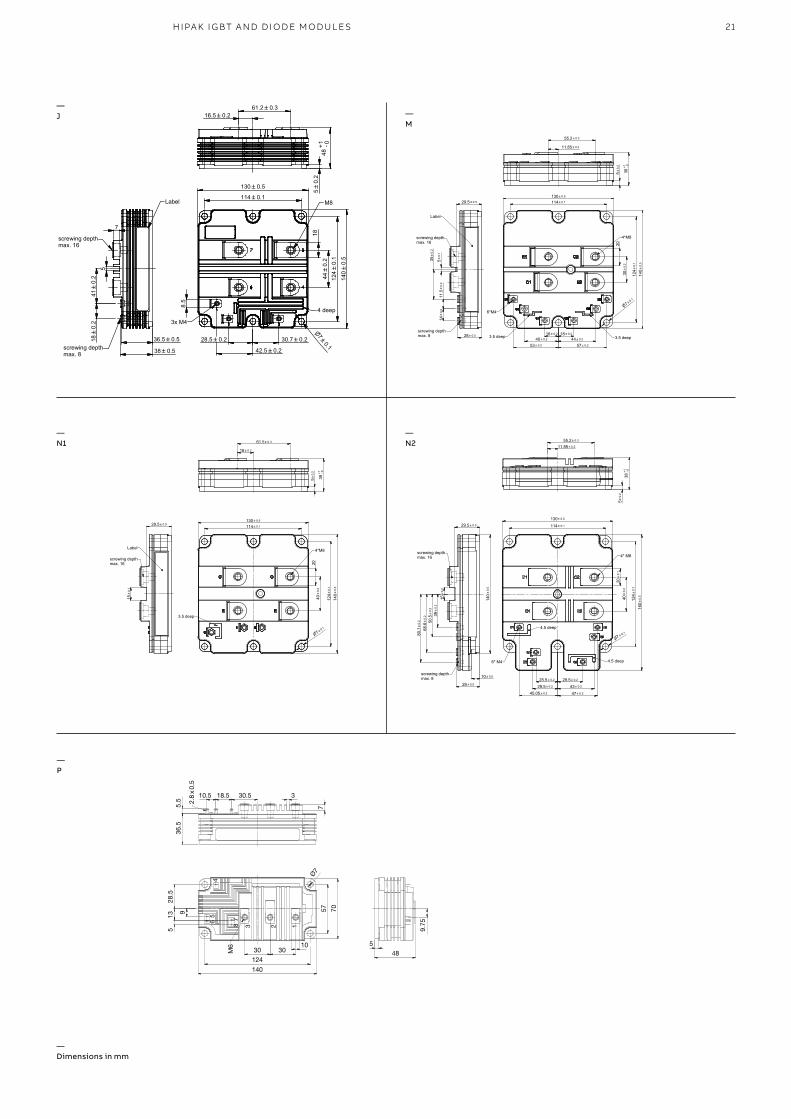
—J —
M
—N1
—N2
—P
— Dimensions in mm

22
—StakPak IGBT press-pack modules
To enhance reliability and reduce cost in systems that require redundancy and series-connected IGBT modules, one should consider using ABB’s StakPaks.
PRO D U C T C ATA LO G P OW ER SEM I CO N D U C TO R S
ABB’s StakPak family uses a well proven concept in IGBT press-pack technology that:
• allows for easy mechanical and electrical series connection
• allows for easy stack design thanks to high tolerance for inhomogeneous mounting pressure
• guarantees a uniform chip pressure in multiple- device stacks
• provides a stable shorted state in case of failure• long-term short-circuit failure mode (SCFM)
available
ABB Semiconductors’ StakPak IGBT modules are therefore a perfect match for applications like HVDC, FACTS, breakers and pulsed power.
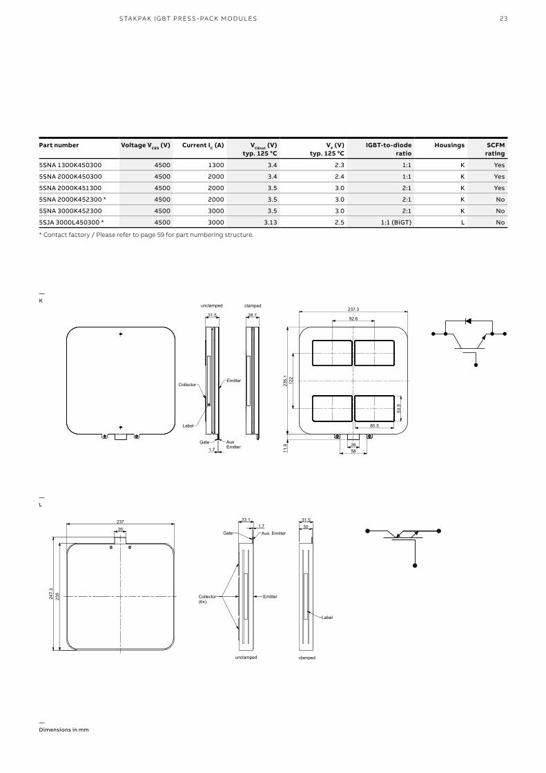
23S TA K PA K I G BT PR E SS - PACK M O D U L E S
Part number Voltage VCES (V) Current IC (A) VCEsat (V)typ. 125 °C
VF (V)typ. 125 °C
IGBT-to-dioderatio
Housings SCFMrating
5SNA 1300K450300 4500 1300 3.4 2.3 1:1 K Yes
5SNA 2000K450300 4500 2000 3.4 2.4 1:1 K Yes
5SNA 2000K451300 4500 2000 3.5 3.0 2:1 K Yes
5SNA 2000K452300 * 4500 2000 3.5 3.0 2:1 K No
5SNA 3000K452300 4500 3000 3.5 3.0 2:1 K No
5SJA 3000L450300 * 4500 3000 3.13 2.5 1:1 (BiGT) L No
* Contact factory / Please refer to page 59 for part numbering structure.
HZN 401 638; DIN 7168 T.1; ISO 2768
General tolerance class for machined parts.Linear- and angular dim.
DIN 7168 T.2:...«medium»«fine» «coarse» Geometrical tolerances
Roughness-symbols according to GZN 020007equivalent to DIN ISO 1302
We reserve all rights in this document and in the information contained therein.
Produced using InventorABB Switzerland Ltd
Reproduction, use or disclosure to third parties without express authority is strictly forbidden.
c
All dimensions in millimeters
2006
X
SemiconductorsABB Switzerland Ltd
Checked by:
Approved by:Replaces:
Revised by:Prepared by:
Filename
Format
Document No.
Lang.Article No. / Description No. of Sh.Sheet
Revision
Scale
Outline DrawingStakPak 4.5kV4 Pocket 5SZL 0407 03
1:1 A3 1 1
048316.idw
30.08.2012 SEMKLBA09.02.2015 CHPESUE
unclamped clamped
31.5 28.792.6
122
85.5
53.9
265811
.9
1.7
AuxEmitter
Gate
Label
CollectorEmitter
237.3
235.
1
26
235
247.
3
237
unclamped clamped
EmitterCollector(6x)
Gate Aux. Emitter
33.11.7
31.530
Label
2016
ISO 2768-mKUnless otherwise specified general tolerance class according to:
All dimensions in millimeters
We reserve all rights in this document and in the information contained therein.Reproduction, use or disclosure to third parties without express authority is strictly forbidden.
ABB Switzerland Ltd c Produced using Inventor SemiconductorsABB Switzerland Ltd
Checked by:Approved by:Replaces:
Revised by:Prepared by:
Filename
Format
Document No.
Article No. / Description No. of Sh.Sheet
Revision
Scale
Outline DrawingMod 6 Pocket
StakPak 52/45 5SZL 0529 01
1:1 A2 1 1
058343.idw
03.02.2016 CHDOTRU1 08.02.201608.02.2016
CHFRDUGCHEMGUS2
unclamped clamped
EmitterCollector(6x)
Gate Aux. Emitter26
235
247.
3
237
44.5 44.5
71.8
71.8
33.11.7
31.530
Label
26
235
247.
3
237
unclamped clamped
EmitterCollector(6x)
Gate Aux. Emitter
33.11.7
31.530
Label
—L
—K
— Dimensions in mm

24
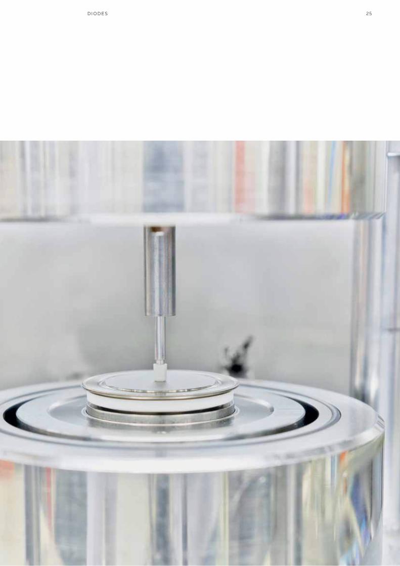
—Diodes
Diodes are used in a number of different applications. Each of these applications sets different requirements on the diodes’ characteristics.
PRO D U C T C ATA LO G P OW ER SEM I CO N D U C TO R S
Inverter applications ask for fast recovery diodes with soft-switching characteristics, high-current rectifiers demand diodes with low on-state losses, medium-power rectifiers benefit from diodes with avalanche capability and welding rectifiers require highest current in the smallest package.
ABB offers four press-pack diode families that meet these requirements:• Fast recovery diodes page 26• Standard rectifier and page 28
avalanche diodes • Welding diodes page 32
25D I O D E S

26
—Fast recovery diodes
ABB Semiconductors’ comprehensive family of fast recovery diodes is optimized for enhanced Safe Operating Area (SOA) and controlled (soft) turn-off recovery.This makes these diodes very well suited for all converter applications.
PRO D U C T C ATA LO G P OW ER SEM I CO N D U C TO R S
ABB has a long history in producing high-power fast recovery diodes for applications such as Voltage Source Inverters (VSIs), Current Source Inverters (CSIs) and snubbers. The diodes are typically used in combination with IGCTs and GTOs as free-wheeling, snubber and clamp diodes, thus enabling full IGCT and GTO perfor-mance.
ABB particularly developed L-housing fast recovery diodes to optimally match press-pack IGBT and IEGT applications where a di/dt of up to 5 kA/µs is required.
Fast recovery diode recommendations for various applications can be found in the ABB application note - Applying fast recovery diodes. The latest version is available at www.abb.com/semiconductors.
Part number VRRM
V
VDC
V
IFAVM
TC = 85 °C
A
IFSM
1 ms 10 ms
TVJM TVJM
kA kA
VF0 rF
TVJM
V mΩ
Irr Qrr
di dt = 300 A/μs
TVJM
A μC
TVJM
°C
RthJC
K/kW
RthCH
K/kW
Fm
kN
Housing
5SDF 13H4501 4500 2800 1200 60.0 25.0 1.30 0.48 800 3000 125 12 3 40 H1
5SDF 10H6004 6000 3800 1100 44.0 18.0 1.50 0.60 1000 6000 125 12 3 40 H1
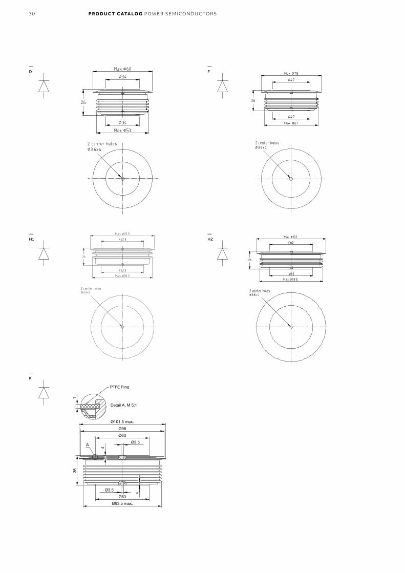
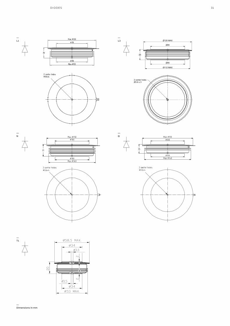
Drawings see page 30.Please refer to page 61 for part numbering structure.
—GTO free-wheeling diodes

27FA S T R ECOV ER Y D I O D E S
Part number VRRM
V
VDC
V
IFAVM
TC = 85 °C
A
IFSM
1 ms 10 ms
TVJM TVJM
kA kA
VF0 rF
TVJM
V mΩ
Irr Qrr
di/dt=100 A/μs
TVJM
A μC
TVJM
°C
RthJC
K/kW
RthCH
K/kW
Fm
kN
Housing
5SDF 05D2501 2500 1100 490 27.0 8.5 1.40 0.50 250 900 125 40 8 11 D
5SDF 03D4501 4500 2400 320 12.0 5.0 2.00 1.50 200 1000 125 40 8 11 D
5SDF 07H4501 4500 2400 900 40.0 16.0 1.80 0.90 260 1700 125 12 3 40 H1
5SDF 02D6002 6000 3000 250 11.4 3.6 2.50 2.50 260 2000 125 40 8 11 D
Part number VRRM
V
VDC
V
IFAVM
TC = 70 °C
A
IFSM
10 ms
TVJM
kA
VF0 rF
TVJM
V mΩ
Irr Qrr
di/dt = 5000 A/μs
TVJM
A μC
TVJM
°C
RthJC
K/kW
RthCH
K/kW
Fm
kN
Housing
5SDF 20L4521 4500 2800 1950 45.0 1.70 0.80 3600 5300 140 6 3 40 L3
5SDF 28L4521 4500 2800 2620 56.0 1.10 0.47 4100 10100 140 6 3 40 L3
Part number VRRM
V
VDC
V
IFAVM
TC = 70 °C
A
IFSM
1 ms 10 ms
TVJM TVJM
kA kA
VF0 rF Irr
TVJM
V mΩ A
di/dt
max.
A/μs
TVJM
°C
RthJC
K/kW
RthCH
K/kW
Fm
kN
Housing
5SDF 03D4502 4500 2800 275 10.0 5.0 2.15 2.80 355 300 115 40 8 16 D
5SDF 05F4502 4500 2800 435 32.0 16.0 2.42 2.10 610 430 115 17 5 20 F
5SDF 10H4503 4500 2800 1100 47.0 20.0 1.75 0.88 1520 600 125 12 3 40 H1
5SDF 20L4520 4500 2800 1970 – 45.0 1.56 0.80 2400 1200 140 6 3 40 L3
5SDF 28L4520 4500 2800 2620 – 56.0 1.10 0.47 2800 1000 140 6 3 40 L3
5SDF 02D6004 5500 3300 175 8.0 3.0 3.35 7.20 300 220 115 40 8 16 D
5SDF 04F6004 5500 3300 380 22.0 10.0 2.70 2.80 600 340 115 22 5 20 F
5SDF 08H6005 5500 3300 585 40.0 18.0 4.50 1.30 900 440 115 12 3 40 H1
Drawings see page 30.Please refer to page 61 for part numbering structure.
—Snubber diodes
—IGBT diodes
—IGCT diodes

28
—Standard rectifier and avalanche diodes
ABB’s two families of high-power rectifier diodes – standard rectifier diodes and avalanche diodes – are well-known for their outstanding reliability and excellent nominal and surge current capabilities.
PRO D U C T C ATA LO G P OW ER SEM I CO N D U C TO R S
The standard rectifier diodes are optimized for line frequency and low on-state losses. Their main applications are rectifiers for large AC drives, aluminum smelting and other metal refining as well as trackside supply.
The avalanche diodes are self-protected against transient overvoltages, offer reduced snubber requirements and feature maximum avalanche power dissipation. They are frequently used for input rectifiers in traction converters or high-voltage power rectifiers.
For safe and easy parallel or series connection, both types of diodes are available in groups of similar VF or Qrr, respectively.
—Standard recovery diodes
Part number VRSM
V
VRRM
V
IFAVM
A
IFSM
10 msTVJM
kA
VT0
TVJM
V
rT
mΩ
TVJM
°C
RthJC
K/kW
RthCH
K/kW
Fm
kN
Housing
5SDD 70H2000 2000 2000 7030 65.0 0.861 0.046 190 8.0 2.5 50 H2
5SDD 65H2400 2400 2400 6520 59.0 0.870 0.057 190 8.0 2.5 50 H2
5SDD 51L2800 2800 2000 5380 65.0 0.770 0.082 175 8.0 3.0 70 L1
5SDD 60N2800 2800 2000 6830 87.0 0.800 0.050 160 5.7 1.0 90 N
5SDD 60Q2800 2800 2000 7385 87.0 0.800 0.050 160 5.0 1.0 90 Q
5SDD 11T2800 2800 2800 1285 15.0 0.933 0.242 160 32.0 8.0 10 T1
5SDD 11D2800 2800 2800 1285 15.0 0.933 0.242 160 32.0 8.0 10 D
5SDD 24F2800 2800 2800 2600 30.0 0.906 0.135 160 15.0 4.0 22 F
5SDD 48H3200 3200 3200 4710 61.0 0.992 0.067 160 8.0 2.5 50 H2
5SDD 54N4000 4000 3600 5200 85.0 0.800 0.086 150 5.7 1.0 90 N
5SDD 40H4000 4000 4000 3847 46.0 0.900 0.133 160 8.0 2.5 50 H2
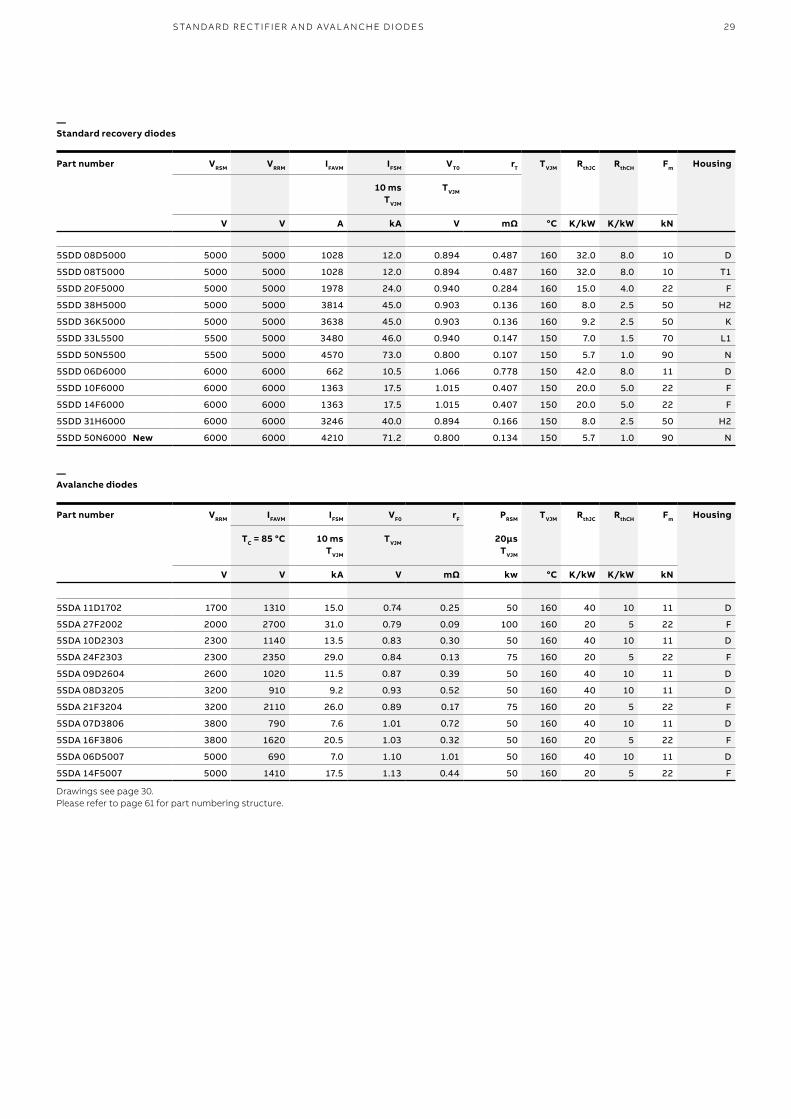
29S TA N DA R D R EC TI FI ER A N D AVA L A N CH E D I O D E S
—Standard recovery diodes
Part number VRSM
V
VRRM
V
IFAVM
A
IFSM
10 msTVJM
kA
VT0
TVJM
V
rT
mΩ
TVJM
°C
RthJC
K/kW
RthCH
K/kW
Fm
kN
Housing
5SDD 08D5000 5000 5000 1028 12.0 0.894 0.487 160 32.0 8.0 10 D
5SDD 08T5000 5000 5000 1028 12.0 0.894 0.487 160 32.0 8.0 10 T1
5SDD 20F5000 5000 5000 1978 24.0 0.940 0.284 160 15.0 4.0 22 F
5SDD 38H5000 5000 5000 3814 45.0 0.903 0.136 160 8.0 2.5 50 H2
5SDD 36K5000 5000 5000 3638 45.0 0.903 0.136 160 9.2 2.5 50 K
5SDD 33L5500 5500 5000 3480 46.0 0.940 0.147 150 7.0 1.5 70 L1
5SDD 50N5500 5500 5000 4570 73.0 0.800 0.107 150 5.7 1.0 90 N
5SDD 06D6000 6000 6000 662 10.5 1.066 0.778 150 42.0 8.0 11 D
5SDD 10F6000 6000 6000 1363 17.5 1.015 0.407 150 20.0 5.0 22 F
5SDD 14F6000 6000 6000 1363 17.5 1.015 0.407 150 20.0 5.0 22 F
5SDD 31H6000 6000 6000 3246 40.0 0.894 0.166 150 8.0 2.5 50 H2
5SDD 50N6000 New 6000 6000 4210 71.2 0.800 0.134 150 5.7 1.0 90 N
Part number VRRM
V
IFAVM
TC = 85 °C
V
IFSM
10 msTVJM
kA
VF0
TVJM
V
rF
mΩ
PRSM
20μsTVJM
kw
TVJM
°C
RthJC
K/kW
RthCH
K/kW
Fm
kN
Housing
5SDA 11D1702 1700 1310 15.0 0.74 0.25 50 160 40 10 11 D
5SDA 27F2002 2000 2700 31.0 0.79 0.09 100 160 20 5 22 F
5SDA 10D2303 2300 1140 13.5 0.83 0.30 50 160 40 10 11 D
5SDA 24F2303 2300 2350 29.0 0.84 0.13 75 160 20 5 22 F
5SDA 09D2604 2600 1020 11.5 0.87 0.39 50 160 40 10 11 D
5SDA 08D3205 3200 910 9.2 0.93 0.52 50 160 40 10 11 D
5SDA 21F3204 3200 2110 26.0 0.89 0.17 75 160 20 5 22 F
5SDA 07D3806 3800 790 7.6 1.01 0.72 50 160 40 10 11 D
5SDA 16F3806 3800 1620 20.5 1.03 0.32 50 160 20 5 22 F
5SDA 06D5007 5000 690 7.0 1.10 1.01 50 160 40 10 11 D
5SDA 14F5007 5000 1410 17.5 1.13 0.44 50 160 20 5 22 F
Drawings see page 30.Please refer to page 61 for part numbering structure.
—Avalanche diodes
30 PRO D U C T C ATA LO G P OW ER SEM I CO N D U C TO R S
—D
—H2
—F
—K
—H1
31D I O D E S
«fin
e»«m
ediu
m»
Geo
met
rical
tole
ranc
esLi
near
-and
angu
lard
im.
HZN
401
638;
DIN
7168
T.1;
ISO
2768
DIN
7168
T.2:
...«c
oars
e»R
epro
duct
ion,
use
ordi
sclo
sure
toth
irdpa
rties
with
oute
xpre
ssau
thor
ityis
stric
tlyfo
rbid
den.
We
rese
rve
allr
ight
sin
this
docu
men
tand
inth
ein
form
atio
nco
ntai
ned
ther
ein.
Roug
hnes
s-sy
mbo
lsac
cord
ing
toG
ZN02
0007
equi
vale
ntto
DIN
ISO
1302
Gen
eral
tole
ranc
ecla
ssfo
rmac
hine
dpa
rts.
Pro
duce
dus
ing
Inve
ntor
AB
BS
witz
erla
ndLt
dc
Alld
imen
sions
inm
illim
eter
s
2015
X
SemiconductorsABB Switzerland Ltd
Checked by:
ABB
Approved by:Replaced by:
Revised by:Prepared by:
Filename
Format
Document No.
Article No. / Description No. of Sh.Sheet
Revision
Scale
5SDF 20L4521KatalogbildDiode 5" LTB 5SYK 5500 01
1:1 A4 1 1
054667.idw
22.01.2015 CHMAZET1
26
n85
n120 MAX
n85
112 MAXØ
2 center holesØ3.6 x 3
—L3
—N
—Q
—T1
—L1
— Dimensions in mm
32
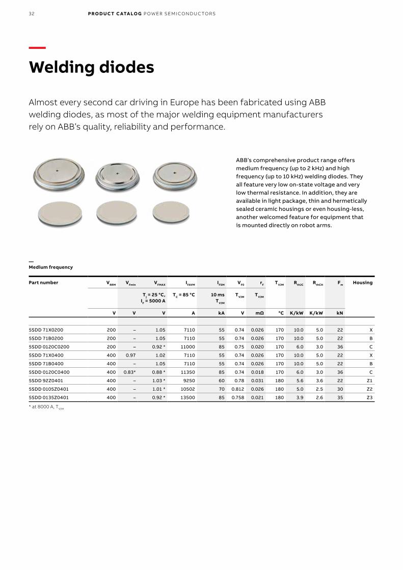
—Welding diodes
Almost every second car driving in Europe has been fabricated using ABB welding diodes, as most of the major welding equipment manufacturers rely on ABB’s quality, reliability and performance.
PRO D U C T C ATA LO G P OW ER SEM I CO N D U C TO R S
ABB’s comprehensive product range offers medium frequency (up to 2 kHz) and high frequency (up to 10 kHz) welding diodes. They all feature very low on-state voltage and very low thermal resistance. In addition, they are available in light package, thin and hermetically sealed ceramic housings or even housing-less,another welcomed feature for equipment that is mounted directly on robot arms.
—Medium frequency
Part number VRRM
V
VFmin
V
VFMAX
Tj = 25 °C,IF = 5000 A
V
IFAVM
TC = 85 °C
A
IFSM
10 msTVJM
kA
VF0
TVJM
V
rF
TVJM
mΩ
TVJM
°C
RthJC
K/kW
RthCH
K/kW
Fm
kN
Housing
5SDD 71X0200 200 – 1.05 7110 55 0.74 0.026 170 10.0 5.0 22 X
5SDD 71B0200 200 – 1.05 7110 55 0.74 0.026 170 10.0 5.0 22 B
5SDD 0120C0200 200 – 0.92 * 11000 85 0.75 0.020 170 6.0 3.0 36 C
5SDD 71X0400 400 0.97 1.02 7110 55 0.74 0.026 170 10.0 5.0 22 X
5SDD 71B0400 400 – 1.05 7110 55 0.74 0.026 170 10.0 5.0 22 B
5SDD 0120C0400 400 0.83* 0.88 * 11350 85 0.74 0.018 170 6.0 3.0 36 C
5SDD 92Z0401 400 – 1.03 * 9250 60 0.78 0.031 180 5.6 3.6 22 Z1
5SDD 0105Z0401 400 – 1.01 * 10502 70 0.812 0.026 180 5.0 2.5 30 Z2
5SDD 0135Z0401 400 – 0.92 * 13500 85 0.758 0.021 180 3.9 2.6 35 Z3
* at 8000 A, TVJM

33W EL D I N G D I O D E S
—High frequency
Part number VRRM
V
VFMAX
TVJM
IF = 5000 A
V
IFAVM
TC = 85 °C
A
IFSM
10 msTVJM
kA
VF0
TVJM
V
rF
TVJM
mΩ
Qrr
TVJM
μC
TVJM
°C
RthJC
K/kW
RthCH
K/kW
Fm
kN
Housing
5SDF 63B0400 400 1.14 6266 44 0.96 0.036 180 190 10.0 5.0 22 B
5SDF 63X0400 400 1.14 6266 44 0.96 0.036 180 190 10.0 5.0 22 X
5SDF 90Z0401 400 1.13 9041 48 0.98 0.032 200 190 5.6 3.6 22 Z1
5SDF 0102C0400 400 1.14 * 10159 70 0.98 0.022 300 190 6.0 3.0 35 C
5SDF 0103Z0401 400 1.20 * 10266 54 1.00 0.027 230 190 5.0 2.5 30 Z2
5SDF 0131Z0401 400 1.14 * 13058 70 0.98 0.022 300 190 3.9 2.6 35 Z3
* at 8000 APlease refer to page 61 for part numbering structure.
—B
—Z1
—C
—X
—Z3
A
C Ø47
Ø53
Ø53
5±0,
3 Withoutcenter hole
A
C Ø49,5
Ø56
Ø56
5±0,
3 Withoutcenter hole
A
C Ø57
Ø63,5
Ø63,5
5±0,
3 Withoutcenter hole
—Z2
— Dimensions in mm
34
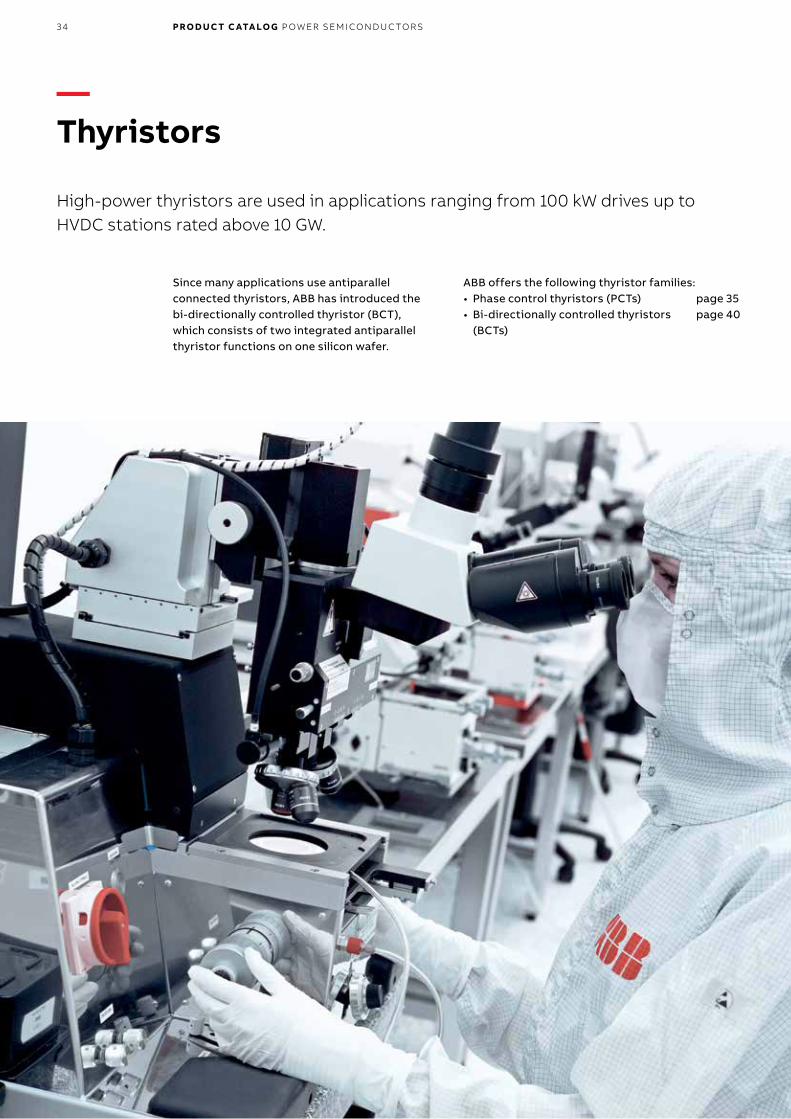
—Thyristors
High-power thyristors are used in applications ranging from 100 kW drives up to HVDC stations rated above 10 GW.
PRO D U C T C ATA LO G P OW ER SEM I CO N D U C TO R S
Since many applications use antiparallel connected thyristors, ABB has introduced the bi-directionally controlled thyristor (BCT), which consists of two integrated antiparallel thyristor functions on one silicon wafer.
ABB offers the following thyristor families:• Phase control thyristors (PCTs) page 35• Bi-directionally controlled thyristors page 40
(BCTs)

35P C TS – PH A SE CO NTR O L TH Y R IS TO R S
—PCTs Phase control thyristors
ABB Semiconductors’ phase control thyristor has been the backbone of the high-power electronics industry since its introduction almost 50 years ago and has set benchmark reliability records over many years.
The field of PCT applications ranges from kW drives and MW rated line commutated frequency converters to GW converters for HVDC trans-mission.
ABB was the first company to introduce 6“ thyristor products and offers the most complete range of high-power thyristors. New thyristor products continue to be developed with focus on minimizing overall losses and maximizing the power rating of the device.
Applications using two antiparallel thyristors can take advantage of ABB‘s innovative bi-directionally controlled thyristors (BCTs) that incorporate two antiparallel thyristors in a single housing (see page 40).

36 PRO D U C T C ATA LO G P OW ER SEM I CO N D U C TO R S
Part number VDRM, VRRM
TVJM
V
ITAVM
TC = 70 °C
A
ITSM
10 ms / TVJM
kA
VT0
TVJM
V
rT
mΩ
TVJM
°C
RthJC
K/kW
RthCH
K/kW
Fm
kN
Housing
5STP 10D1601 1600 969 15.0 0.93 0.302 125 32.0 10.0 10 D
5STP 10T1600 1600 969 15.0 0.93 0.302 125 32.0 10.0 10 T1
5STP 20F1601 1600 1901 27.3 0.95 0.152 125 16.0 4.0 22 F
5STP 20T1600 1600 1956 27.3 0.95 0.152 125 15.5 4.0 22 T2
5STP 34H1601 1600 3370 49.0 0.94 0.066 125 10.0 3.0 50 H
5STP 34T1600 1600 3370 49.0 0.94 0.066 125 10.0 3.0 50 T3
5STP 07D1800 1800 730 9.0 0.80 0.540 125 36.0 7.5 10 D
5STP 09D1801 1800 932 13.7 0.94 0.341 125 32.0 10.0 10 D
5STP 18F1800 1800 1660 21.0 0.83 0.230 125 17.0 4.0 22 F
5STP 18F1801 1800 1825 26.2 0.97 0.170 125 16.0 4.0 22 F
5STP 30H1801 1800 3108 47.0 0.98 0.081 125 10.0 3.0 50 H
5STP 42L1800 1800 4170 64.0 0.85 0.082 125 7.0 1.5 70 L
5STP 50Q1800 1800 6100 94.0 0.90 0.050 125 5.0 1.0 90 Q
5STP 09D2201 2200 863 12.0 0.98 0.414 125 32.0 10.0 10 D
5STP 17F2201 2200 1702 25.5 0.99 0.206 125 16.0 4.0 22 F
5STP 17T2200 2200 1743 25.5 0.99 0.206 125 15.5 4.0 22 T2
5STP 29H2201 2200 2855 45.0 1.00 0.107 125 10.0 3.0 50 H
5STP 06D2800 2800 620 8.8 0.92 0.780 125 36.0 7.5 10 D
5STP 08D2801 2800 792 10.6 1.06 0.492 125 32.0 10.0 10 D
5STP 08T2800 2800 792 10.6 1.06 0.492 125 32.0 10.0 10 T1
5STP 15T2800 2800 1589 23.6 1.02 0.265 125 15.5 4.0 22 T2
5STP 16F2800 2800 1400 18.0 0.82 0.370 125 17.0 4.0 22 F
5STP 16F2801 2800 1554 23.6 1.02 0.265 125 16.0 4.0 22 F
5STP 27H2801 2800 2670 43.0 1.04 0.127 125 10.0 3.0 50 H
5STP 33L2800 2800 3740 65.5 0.95 0.100 125 7.0 1.5 70 L
5STP 45N2800 2800 5080 77.0 0.86 0.070 125 5.7 1.0 90 N
5STP 45Q2800 2800 5490 77.0 0.86 0.070 125 5.0 1.0 90 Q
5STP 04D4200 4200 470 7.1 1.00 1.500 125 36.0 7.5 10 D
5STP 12F4200 4200 1150 17.3 0.95 0.575 125 17.0 4.0 22 F
5STP 21H4200 4200 2192 32.0 1.25 0.191 125 10.0 3.0 50 H
5STP 28L4200 4200 3170 54.0 0.97 0.158 125 7.0 1.5 70 L
5STP 38N4200 4200 3960 64.5 0.95 0.130 125 5.7 1.0 90 N
5STP 38Q4200 4200 4275 64.5 0.95 0.130 125 5.0 1.0 90 Q
5STP 04D5200 5200 440 6.1 1.20 1.600 125 36.0 7.5 10 D
5STP 17H5200 5200 1975 34.0 1.02 0.320 125 10.0 2.0 50 H
5STP 25L5200 5200 2760 50.5 1.00 0.225 125 7.0 1.5 70 L
5STP 25M5200 5200 2379 50.5 1.00 0.225 125 9.0 1.5 70 M
5STP 34N5200 5200 3600 63.0 1.03 0.160 125 5.7 1.0 90 N
5STP 34Q5200 5200 3875 63.0 1.03 0.160 125 5.0 1.0 90 Q
5STP 52U5200 5200 5120 99.0 1.04 0.115 125 4.0 0.8 135 U
5STP 03D6500 6500 380 4.7 1.20 2.300 125 36.0 7.5 10 D
5STP 03X6500 6500 350 4.7 1.20 2.300 125 45.0 7.5 10 X
5STP 08F6500 6500 830 15.1 1.24 1.015 125 17.0 4.0 22 F
5STP 08G6500 6500 720 15.1 1.24 1.015 125 22.0 4.0 22 G
5STP 12K6500 6500 1370 31.5 1.18 0.632 125 11.0 2.0 50 K
5STP 18M6500 6500 1800 47.5 1.20 0.430 125 9.0 1.5 70 M
5STP 26N6500 6500 2810 65.0 1.12 0.290 125 5.7 1.0 90 N
5STP 42U6500 6500 4250 86.0 1.24 0.162 125 4.0 0.8 135 U
5STP 48Y7200 New 7200 4840 92.0 1.06 0.115 110 3.0 0.6 190 Y
5STP 27N8500 New 8500 2450 64.0 1.09 0.420 125 5.7 1.0 90 N
5STP 27Q8500 New 8500 2630 64.0 1.09 0.420 125 5.0 1.0 90 Q
5STP 45Y8500 New 8500 4240 90.0 1.10 0.160 110 3.0 0.6 190 Y
Please refer to page 60 for part numbering structure.
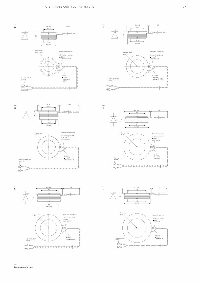
37P C TS – PH A SE CO NTR O L TH Y R IS TO R S
— Dimensions in mm
—D
—F
—H
—K
—G
—L

38
PRO D U C T C ATA LO G P OW ER SEM I CO N D U C TO R S
—M
—N
—Q
—T1
—T2
—T3

39
2 center holes3.6 x 4
138
35
Max 180
Max Ø192
138Ø2 center holes3.6 x 4
138
35
Max 180
Max Ø192
138Ø
P C TS – PH A SE CO NTR O L TH Y R IS TO R S
—U
—X
—Y
— Dimensions in mm
40
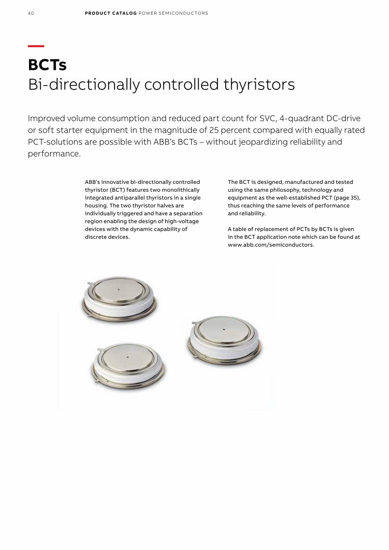
—BCTs Bi-directionally controlled thyristors
Improved volume consumption and reduced part count for SVC, 4-quadrant DC-drive or soft starter equipment in the magnitude of 25 percent compared with equally rated PCT-solutions are possible with ABB’s BCTs – without jeopardizing reliability and performance.
PRO D U C T C ATA LO G P OW ER SEM I CO N D U C TO R S
ABB’s innovative bi-directionally controlled thyristor (BCT) features two monolithically integrated antiparallel thyristors in a single housing. The two thyristor halves are individually triggered and have a separation region enabling the design of high-voltage devices with the dynamic capability of discrete devices.
The BCT is designed, manufactured and tested using the same philosophy, technology and equipment as the well-established PCT (page 35), thus reaching the same levels of performance and reliability.
A table of replacement of PCTs by BCTs is given in the BCT application note which can be found at www.abb.com/semiconductors.
41
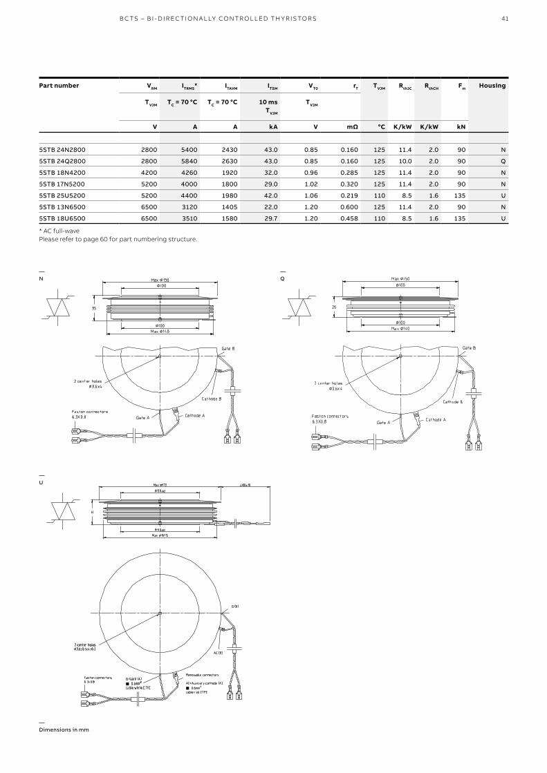
B C TS – B I - D I R EC TI O N A L LY CO NTR O L L ED TH Y R IS TO R S
Part number VRM
TVJM
V
ITRMS*
TC = 70 °C
A
ITAVM
TC = 70 °C
A
ITSM
10 msTVJM
kA
VT0
TVJM
V
rT
mΩ
TVJM
°C
RthJC
K/kW
RthCH
K/kW
Fm
kN
Housing
5STB 24N2800 2800 5400 2430 43.0 0.85 0.160 125 11.4 2.0 90 N
5STB 24Q2800 2800 5840 2630 43.0 0.85 0.160 125 10.0 2.0 90 Q
5STB 18N4200 4200 4260 1920 32.0 0.96 0.285 125 11.4 2.0 90 N
5STB 17N5200 5200 4000 1800 29.0 1.02 0.320 125 11.4 2.0 90 N
5STB 25U5200 5200 4400 1980 42.0 1.06 0.219 110 8.5 1.6 135 U
5STB 13N6500 6500 3120 1405 22.0 1.20 0.600 125 11.4 2.0 90 N
5STB 18U6500 6500 3510 1580 29.7 1.20 0.458 110 8.5 1.6 135 U
* AC full-wavePlease refer to page 60 for part numbering structure.
—N
—Q
—U
— Dimensions in mm

42
—IGCTs Integrated gate-commutated thyristors
Within 20 years of its introduction, the IGCT has established itself as the semiconductor of choice for high-power frequency converters by meeting the requirements of today’s demanding applications.
PRO D U C T C ATA LO G P OW ER SEM I CO N D U C TO R S
ABB Semiconductors’ IGCTs are used in a multi-tude of applications due to their versatility, efficiency and cost-effectiveness. With their low on-state voltage, they achieve the lowest running costs by reaching inverter efficiencies of 99.6 percent and more.
Single inverters of over 15 MVA can be realized without series or parallel connection, thus achieving the highest inverter power densities in the industry.
The number of applications featuring IGCTs is manifold: medium-voltage drives (MVDs), marine drives, co-generation, wind power converters and STATCOMs, to name just a few.
The latest record performance using IGCTs was achieved with the world’s most powerful frequency converter (100 MVA) for variable speed pumped hydropower application that ABB has installed to the Grimsel 2 power plant in the Swiss Alps.

43I G C TS – I NTEG R ATED G ATECO M M U TATED TH Y R IS TO R S
Part number VDRM
V
VDC
V
VRRM
V
ITGQM
A
ITAVM
TC = 85 °C
A
ITSM
3 msTVJM
kA
10 msTVJM
kA
VT
4000 A TVJM
V
VT0
TVJM
V
rT
TVJM
mΩ
TVJM
°C
RthJC
K/kW
RthCH
K/kW
Fm
kN
VGIN
V
Outline
5SHY 35L4520 4500 2800 17 4000 1700 50 32 2.70 1.40 0.33 125 8.5 3 40 28-40 Fig. 1
5SHY 35L4521 4500 2800 17 4000 1700 50 32 2.70 1.40 0.33 125 8.5 3 40 28-40 Fig. 1
5SHY 35L4522 4500 2800 17 4000 2100 56 35 2.00 1.15 0.21 125 8.5 3 40 28-40 Fig. 1
5SHY 40L4511 4500 2800 17 3600 1430 39 28 3.50 1.70 0.45 125 8.5 3 40 28-40 Fig. 1
5SHY 55L4500 4500 2800 17 5000 1870 50 33 2.35 1.22 0.28 125 8.5 3 40 28-40 Fig. 1
5SHY 50L5500 5500 3300 17 3600 1290 40 26 4.10 1.66 0.62 125 8.5 3 40 28-40 Fig. 1
5SHY 42L6500 6500 4000 17 3800 1290 40 26 4.10 1.88 0.56 125 8.5 3 40 28-40 Fig. 1
- Optimized for snubberless turn-off- Contact factory for series connection
Part number VDRM
V
VDC
V
ITGQM
A
ITAVM /IFAVM
TC = 85 °C
A
ITSM /IFSM
10 msTVJM
kA
VT /VF
ITGQM TVJM
V
VT0 V/F0
TVJM
V
rT /rF
mΩ
di/dtmax.
A/μs
Irr
A
TVJM
°C
RthJC
K/kW
Fm
kN
VGIN
V
Outline
5SHX 26L4520 GCT 4500 2800 2200 1010 17.0 2.95 1.80 0.53 13
Diode part 390 10.6 5.40 2.70 1.24 650 900 125 26 44 28-40 Fig. 1
5SHX 19L6020 GCT 5500 3300 1800 840 18.0 3.45 1.90 0.90 13
Diode part 340 7.7 6.40 2.70 2.23 510 780 125 26 44 28-40 Fig. 1
- Monolithically integrated free-wheeling diode optimized for snubberless turn-offPlease refer to page 60 for part numbering structure.
—Asymmetric IGCTs
—Reverse conducting IGCTs

44 PRO D U C T C ATA LO G P OW ER SEM I CO N D U C TO R S
—Fig. 1
— Dimensions in mm
Fast recovery diode recommendationFor all asymmetric and reverse conducting IGCTs, ABB offers matching free-wheeling, neutral point (NPC) and clamp diodes. The actual choice of the diode depends on the specific application. Please see applica-tion note 5SYA 2064, Applying fast recovery diodes, on www.abb.com/semiconductors.

45I G C TS – I NTEG R ATED G ATECO M M U TATED TH Y R IS TO R S
46
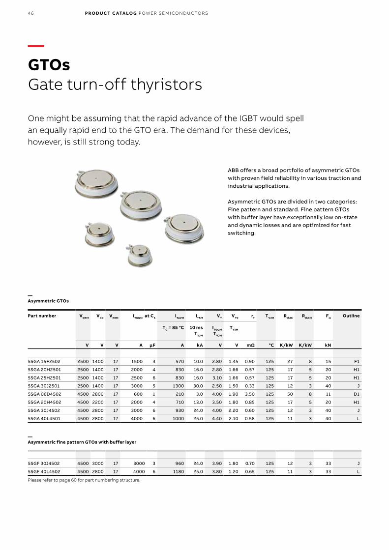
—GTOs Gate turn-off thyristors
One might be assuming that the rapid advance of the IGBT would spell an equally rapid end to the GTO era. The demand for these devices, however, is still strong today.
PRO D U C T C ATA LO G P OW ER SEM I CO N D U C TO R S
ABB offers a broad portfolio of asymmetric GTOs with proven field reliability in various traction and industrial applications.
Asymmetric GTOs are divided in two categories: Fine pattern and standard. Fine pattern GTOs with buffer layer have exceptionally low on-state and dynamic losses and are optimized for fast switching.
Part number VDRM
V
VDC
V
VRRM
V
ITGQM
A
at CS
μF
ITAVM
TC = 85 °C
A
ITSM
10 msTVJM
kA
VT
ITGQM TVJM
V
VT0
TVJM
V
rT
mΩ
TVJM
°C
RthJC
K/kW
RthCH
K/kW
Fm
kN
Outline
5SGA 15F2502 2500 1400 17 1500 3 570 10.0 2.80 1.45 0.90 125 27 8 15 F1
5SGA 20H2501 2500 1400 17 2000 4 830 16.0 2.80 1.66 0.57 125 17 5 20 H1
5SGA 25H2501 2500 1400 17 2500 6 830 16.0 3.10 1.66 0.57 125 17 5 20 H1
5SGA 30J2501 2500 1400 17 3000 5 1300 30.0 2.50 1.50 0.33 125 12 3 40 J
5SGA 06D4502 4500 2800 17 600 1 210 3.0 4.00 1.90 3.50 125 50 8 11 D1
5SGA 20H4502 4500 2200 17 2000 4 710 13.0 3.50 1.80 0.85 125 17 5 20 H1
5SGA 30J4502 4500 2800 17 3000 6 930 24.0 4.00 2.20 0.60 125 12 3 40 J
5SGA 40L4501 4500 2800 17 4000 6 1000 25.0 4.40 2.10 0.58 125 11 3 40 L
5SGF 30J4502 4500 3000 17 3000 3 960 24.0 3.90 1.80 0.70 125 12 3 33 J
5SGF 40L4502 4500 2800 17 4000 6 1180 25.0 3.80 1.20 0.65 125 11 3 33 L
Please refer to page 60 for part numbering structure.
—Asymmetric GTOs
—Asymmetric fine pattern GTOs with buffer layer

47
34Ø
26
53 MAX
34Ø 60 MAX
Ø
Ø
A
C
200
(170)
Ø3.6
Coaxial cableInsulation: Core PTFE Screen FEP
Ø4.3
G
AC
2 center holesØ 3.5 x 2 deep
G
Soldered faston connectors
A = AnodeC = CathodeG = Gate, 2 mm (AWG 12) cable whiteAC = Auxiliary cathode, 1 mm cable black
Dimensions in mm
2
2
AC
27
93.5 MAXØ62.8Ø
62.8Ø90.2 MAXØ
440
(400)
Ø5.5
Coaxial cableInsulation: Core ETFE Screen ETFE
G
2 center holesØ 3.6 x 2 deep
AC
Soldered faston connectors
G
AC
Ø5.3
A = AnodeC = CathodeG = Gate, 3 mm (AWG 12) cable whiteAC = Auxiliary cathode, 3.5 mm cable black
Dimensions in mm
2
2
85Ø
26
119.3 MAXØ
85120.5 MAXØ
Ø
2 center holesØ 3.6 x 3 deep
460
7.3Ø
(400)
Coaxial cableInsulation: EVA (Radox GKW - A
AC
G
G
AC
5.3Ø
Soldered faston connectorSoldered socketconnector
A = AnodeC = CathodeG = Gate, 6 mm (AWG 12) cable whiteAC = Auxiliary cathode, 6 mm cable black
Dimensions in mm
2
2
75Ø
26
105.6 MAXØ
75108.5 MAXØ
Ø
2 center holesØ 3.6 x 3 deep
455
5.5Ø
(400)
Coaxial cableInsulation: Core ETFE Screen ETFE
AC
G
G
AC
5.3Ø
Soldered faston connectorSoldered socketconnector
A = AnodeC = CathodeG = Gate, 3 mm (AWG 12) cable whiteAC = Auxiliary cathode, 3.5 mm cable black
Dimensions in mm
2
2
G TOS – G ATE T U R N - O FF TH Y R IS TO R S
—D1
—F1
—H1
—L
—J
— Dimensions in mm
Fast recovery diode recommendationFor all GTO types, ABB offers matching free-wheeling and snubber diodes. The actual choice of the diode depends on the specific application. Please see application note 5SYA 2064, Applying fast recovery diodes, on www.abb.com/semiconductors.
47Ø
25.7
0.3
67 MAX
47Ø 75 MAX
Ø
Ø
±
A
C
430
(400)
Ø5.5
Coaxial cableInsulation: Core ETFE Screen ETFE
Ø5.3
G
AC
2 center holesØ 3.6 x 3 deep
AC
G
Soldered faston connectors
A = AnodeC = CathodeG = Gate, 3 mm (AWG 12) cable whiteAC = Auxiliary cathode, 3.5 mm cable black
Dimensions in mm
2
2
48
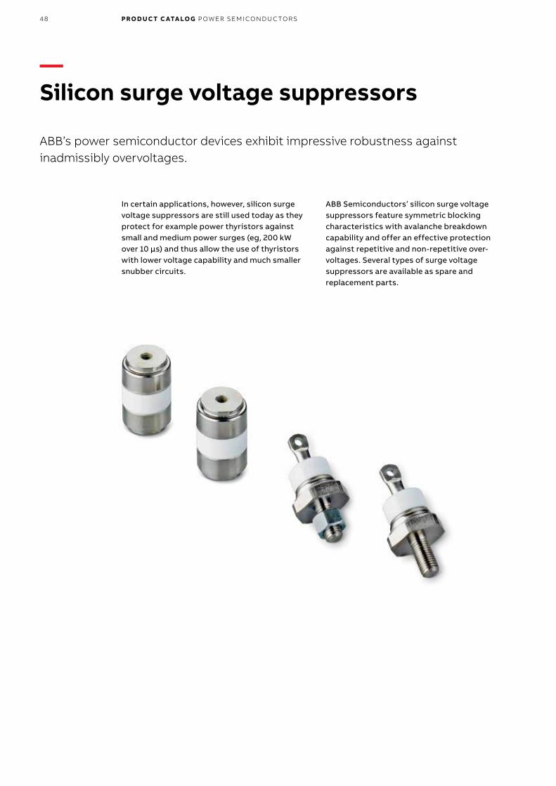
—Silicon surge voltage suppressors
ABB’s power semiconductor devices exhibit impressive robustness against inadmissibly overvoltages.
PRO D U C T C ATA LO G P OW ER SEM I CO N D U C TO R S
In certain applications, however, silicon surge voltage suppressors are still used today as they protect for example power thyristors against small and medium power surges (eg, 200 kW over 10 μs) and thus allow the use of thyristors with lower voltage capability and much smaller snubber circuits.
ABB Semiconductors’ silicon surge voltage suppressors feature symmetric blocking characteristics with avalanche breakdown capability and offer an effective protection against repetitive and non-repetitive over-voltages. Several types of surge voltage suppressors are available as spare and replacement parts.

49
Part number VR
TVJ = 60 °C
V
Tolerance
TVJ = 60 °C
V
10 μs
A
100 μs
A
IRM for
1 ms
A
base width
10 ms
A
TVJM
°C
RthJC
K/kW
Housing
5SSA 50R**00 500, 600 ±60 500 135 33 7.5 125 600 R
5SSA 38R**00 700, 800 ±60 380 100 25 4.5 125 600 R
5SSA 30R**00 900, 1000 ±60 300 80 21 4.0 125 600 R
5SSA 26R**00 1100, 1200 ±60 260 67 18 3.6 125 600 R
5SSA 23R**00 1300, 1400 ±60 230 58 15 3.4 125 600 R
5SSA 20R**00 1500, 1600 ±60 200 50 13 3.0 125 600 R
5SSB 50X**00 450, 550 ±50 500 135 33 7.5 125 500 X
5SSB 38X**00 650, 750 ±50 380 100 25 4.5 125 500 X
5SSB 30X**00 850, 950 ±50 300 80 21 4.0 125 500 X
5SSB 26X**00 1050, 1150 ±50 260 67 18 3.6 125 500 X
5SSB 23X**00 1250, 1350 ±50 230 58 15 3.4 125 500 X
5SSB 20X**00 1450, 1550 ±50 200 50 13 3.0 125 500 X
5SSB 30X**00 1650, 1750, 1850, 1950 ±50 300 80 21 4.0 125 250 X
5SSB 26X**00 2050, 2150, 2250, 2350 ±50 260 67 18 3.6 125 250 X
5SSB 23X**00 2450, 2550, 2650, 2750 ±50 230 58 15 3.4 125 250 X
5SSB 20X**00 2850, 2950 ±50 200 50 13 3.0 125 250 X
** = VR/100 VPlease refer to page 61 for part numbering structure.
S I L I CO N SU R G E VO LTAG E SU PPR E SSO R S
—R
—X
— Dimensions in mm

50
—Test systems for high-power semiconductors
ABB Semiconductors is well known as one of the leading suppliers of powersemiconductors. Good to know that ABB Semiconductors also designs, manufactures and offers CE compliant customized power semiconductor test systems.
PRO D U C T C ATA LO G P OW ER SEM I CO N D U C TO R S
More than 30 years of experience and proximity to semiconductor development, production and application enable ABB to offer test systems for various environments like research & develop-ment, laboratory, production or failure analysis.Highest quality assurance, safe handling, as well as remote or on-site service capability are guaranteed.
High-power semiconductor test systemsABB offers static and dynamic production test systems for most types of power semiconductor devices like diodes, PCTs, BCTs, GTOs, IGCTs and IGBTs. They can handle dies, substrates, submodules, modules, wafers and press-pack devices. Also reliability test systems for high temperature reverse bias, intermittent operating life or surge current tests are available. Auxiliary tester parts include clamping, capacitor discharge, pre-heating, data acquisition and parameter extraction units as well as program-mable IGBT and thyristor gate units.
ParametersThe ABB test systems cover the range of up to 14 kV and 10 kA and use configurable stray inductances down to 60 nH. During testing, the clamped device under test (DUT) can be precisely heated up to 200 °C for production systems or cooled down to -40 °C in an environmental chamber for engineering systems. The clamping units can handle devices up to 240 mm in diameter and can apply a clamping force of up to 240 kN.
AutomationOur test systems are designed for easy integra-tion into automated handling equipment. The test system’s software is compatible to commer-cial control systems such as manufacturing execution systems (MES) and computer-aided quality assurance (CAQ).

51TE S T S Y S TEMS
Bipolar test systems 4.5 kV
Thyristor and diode static / dynamic X X X X X X
GTO and diode static X X X X
GTO and diode dynamic X X X
IGBT test systems
IGBT and diode dies static X X X
IGBT and diode substrates static / dynamic X X X X X
IGBT and diode modules static X X X
IGBT and diode modules dynamic X X
Baseplates flatness
Blo
ckin
g vo
ltag
e A
C o
r D
C
Gat
e ch
arac
teri
stic
s
On-
stat
e, f
orw
ard
volt
age
Rev
erse
rec
over
y ch
arg
e
Cri
tica
l dV/
dt
Cir
cuit
-co
mm
utat
ed t
urn-
off
tim
e
Vce
sat /
Vp
inch
-off
Turn
-on
/ tu
rn-o
ff
Reliability test systems• High temperature reverse bias• Intermittent operating life• Surge current
Auxiliary unit• Clamping unit• Capacitor discharge unit• Pre-heating unit• Programmable IGBT and thyristor gate units• Data acquisition and parameter extraction units
52
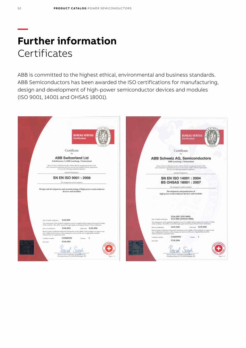
—Further informationCertificates
ABB is committed to the highest ethical, environmental and business standards.ABB Semiconductors has been awarded the ISO certifications for manufacturing, design and development of high-power semiconductor devices and modules (ISO 9001, 14001 and OHSAS 18001).
PRO D U C T C ATA LO G P OW ER SEM I CO N D U C TO R S

53CERTIFI C ATE S

54
—Further informationREACH Declaration
PRO D U C T C ATA LO G P OW ER SEM I CO N D U C TO R S
55S Y M B O L S
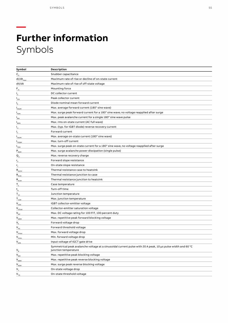
—Further informationSymbols
Symbol Description
CS Snubber capacitance
di/dtmax Maximum rate of rise or decline of on-state current
dV/dt Maximum rate of rise of off-state voltage
Fm Mounting force
IC DC collector current
ICM Peak collector current
IF Diode nominal mean forward current
IFAVM Max. average forward current (180° sine wave)
IFSM Max. surge peak forward current for a 180° sine wave; no voltage reapplied after surge
IRM Max. peak avalanche current for a single 180° sine wave pulse
IRMS Max. rms on-state current (AC full wave)
Irr Max. (typ. for IGBT diode) reverse recovery current
IT Forward current
ITAVM Max. average on-state current (180° sine wave)
ITGQM Max. turn-off current
ITSM Max. surge peak on-state current for a 180° sine wave; no voltage reapplied after surge
PRSM Max. surge avalanche power dissipation (single pulse)
Qrr Max. reverse recovery charge
rF Forward slope resistance
rT On-state slope resistance
RthCH Thermal resistance case to heatsink
RthJC Thermal resistance junction to case
RthJH Thermal resistance junction to heatsink
TC Case temperature
tq Turn-off time
TVJ Junction temperature
TVJM Max. junction temperature
VCES IGBT collector-emitter voltage
VCEsat Collector-emitter saturation voltage
VDC Max. DC voltage rating for 100 FIT, 100 percent duty
VDRM Max. repetitive peak forward blocking voltage
VF Forward voltage drop
VF0 Forward threshold voltage
VFmax Max. forward voltage drop
VFmin Min. forward voltage drop
VGIN Input voltage of IGCT gate drive
VR
Symmetrical peak avalanche voltage at a sinusoidal current pulse with 20 A peak, 10 μs pulse width and 60 °C junction temperature
VRM Max. repetitive peak blocking voltage
VRRM Max. repetitive peak reverse blocking voltage
VRSM Max. surge peak reverse blocking voltage
VT On-state voltage drop
VT0 On-state threshold voltage

56
—Further informationDocumentation
PRO D U C T C ATA LO G P OW ER SEM I CO N D U C TO R S
—IGBT dies and modules
—Diodes
—Thyristors
Document title Document number
Mounting instructions for StakPaks 5SYA 2037
Mounting instructions for HiPak modules 5SYA 2039
Failure rates of IGBT due to cosmic rays 5SYA 2042
Load-cycling capability of HiPak IGBT modules 5SYA 2043
Thermal runaway during blocking 5SYA 2045
Voltage ratings of high-power semiconductors 5SYA 2051
Applying IGBTs 5SYA 2053
IGBT diode safe operating area 5SYA 2057
Surge currents for IGBT diodes 5SYA 2058
Applying IGBT and diode dies 5SYA 2059
Thermal design and temperature ratings of IGBT modules 5SYA 2093
Paralleling of IGBT modules 5SYA 2098
Mounting Instructions for 62Pak 5SYA 2106
Mounting instructions for LinPak modules 5SYA 2107
Document title Document number
High-current rectifier diodes for welding applications 5SYA 2013
Design of RC snubbers for phase control applications 5SYA 2020
High-power rectifier diodes 5SYA 2029
Mechanical clamping of press-pack high-power semiconductors 5SYA 2036
Field measurements on high-power press-pack semiconductors 5SYA 2048
Voltage ratings of high-power semiconductors 5SYA 2051
Failure rates of fast recovery diodes due to cosmic rays 5SYA 2061
Applying fast recovery diodes 5SYA 2064
Parameter selection of high-power semiconductor for series and parallel connection 5SYA 2091
Document title Document number
Bi-directionally controlled thyristors 5SYA 2006
Design of RC snubbers for phase control applications 5SYA 2020
Gate-drive recommendations for phase control and bi-directionally controlled thyristors 5SYA 2034
Mechanical clamping of press-pack high-power semiconductors 5SYA 2036
Field measurements on high-power press-pack semiconductors 5SYA 2048
Voltage definitions for phase control and bi-directionally controlled thyristors 5SYA 2049
Voltage ratings of high-power semiconductors 5SYA 2051
Switching losses for phase control and bi-directionally controlled thyristors 5SYA 2055
Parameter selection of high-power semiconductor for series and parallel connection 5SYA 2091
Surge currents for phase control thyristors 5SYA 2102

57D O C U M ENTATI O N
—IGCTs
—GTOs
—Environmental specifications
Document title Document number
Applying IGCT gate units 5SYA 2031
Applying IGCTs 5SYA 2032
Mechanical clamping of press-pack high-power semiconductors 5SYA 2036
Failure rates of IGCTs due to cosmic rays 5SYA 2046
Field measurements on high-power press-pack semiconductors 5SYA 2048
Voltage ratings of high-power semiconductors 5SYA 2051
Document title Document number
Mechanical clamping of press-pack high-power semiconductors 5SYA 2036
Field measurements on high-power press-pack semiconductors 5SYA 2048
Voltage ratings of high-power semiconductors 5SYA 2051
Document title Document number
Storage of diodes, PCTs, GTOs 5SZK 9104
Transport of diodes, PCTs and GTOs 5SZK 9105
Operation of pressure contact IGCTs 5SZK 9107
Storage of IGCTs 5SZK 9109
Transport of IGCTs 5SZK 9110
Storage of HiPaks 5SZK 9111
Transport of HiPaks 5SZK 9112
Operation of industry HiPaks 5SZK 9113
Handling, packing and storage conditions for sawn wafer dies and bare dies 5SZK 9114
Operation of industry press-pack diodes, PCTs and GTOs 5SZK 9115
Operation of traction press-pack diodes, PCTs and GTOs 5SZK 9116
Operation of traction HiPaks 5SZK 9120
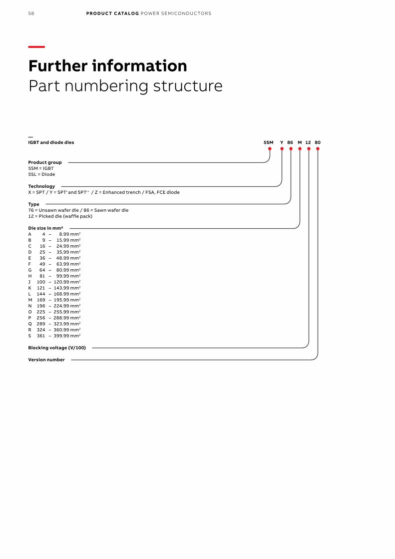
58
5SM Y 86 M 12 80
—Further informationPart numbering structure
PRO D U C T C ATA LO G P OW ER SEM I CO N D U C TO R S
—IGBT and diode dies
Product group5SM = IGBT5SL = Diode
TechnologyX = SPT / Y = SPT+ and SPT++ / Z = Enhanced trench / FSA, FCE diode
Type76 = Unsawn wafer die / 86 = Sawn wafer die12 = Picked die (waffle pack)
Die size in mm2A 4 – 8.99 mm2 B 9 – 15.99 mm2
C 16 – 24.99 mm2 D 25 – 35.99 mm2 E 36 – 48.99 mm2 F 49 – 63.99 mm2 G 64 – 80.99 mm2 H 81 – 99.99 mm2 J 100 – 120.99 mm2 K 121 – 143.99 mm2 L 144 – 168.99 mm2 M 169 – 195.99 mm2 N 196 – 224.99 mm2 O 225 – 255.99 mm2 P 256 – 288.99 mm2 Q 289 – 323.99 mm2 R 324 – 360.99 mm2 S 361 – 399.99 mm2
Blocking voltage (V/100)
Version number

59
5SND 0800 M 17 0 1 00
PA RT N U M B ER I N G S TR U C T U R E
—IGBT and diode modules
Product group5SJA = BiGT module5SLA = Single diode module5SLD = Duale diode module5SLG = Phase leg diode modules5SNA = Single IGBT module / IGBT press-pack5SND = Duale IGBT module5SNE = Low side chopper5SNG = Phase leg IGBT module
Nominal collector current rating (A)
HousingE = HiPak2, 40 mm G = HiPak2 HV, 44 mm H = Press-pack standard J = HiPak1 HV, 44 mm K = Press-pack L = Press-pack M = HiPak1, 30 mm N1 & N2 = HiPak1, 40 mmP = HiPak0Q = 62PakR = LoPak1S = LoPak3X = LinPak
Blocking voltage (V/100)
Package variation0 = Standard
Technology variation1 = SPT / 3 = SPT+ and SPT++
Version number

60
Product group5SHX = Reverse conducting IGCT5SHY = Asymmetric IGCT
Max. turn-off current (l/100)
Housing
Blocking voltage (V/100)
Version number
PRO D U C T C ATA LO G P OW ER SEM I CO N D U C TO R S
5SHY 35 L 45 20
5SGA 20 H 25 01
5STP 26 N 65 00
—IGCT
—GTO
—Phase control thyristors
Product group5SGA = Asymmetric GTO5SGF = Fine pattern GTO
Max. turn-off current (l/100)
Housing
Blocking voltage (V/100)
Version number
Product group5STP = Phase control thyristors5STB = Bi-directionally controlled thyristors
Average on-state current (l/100)
Housing
Blocking voltage (V/100)
Version number

61
Product group5SSA = Standard5SSB = Press-pack
Pulsed current (l/100)
Housing
Blocking voltage (V/100)
Version number
5SDA 14 F 50 07
5SSA 50 R 06 00
PA RT N U M B ER I N G S TR U C T U R E
—Diodes
—Surge voltage suppressors
Product group5SDA = Avalanche rectifier diode5SDD = Rectifier diode5SDF = Fast recovery diode
Average on-state current (l/100)
Housing
Blocking voltage (V/100)
Version number

62
—Further informationPerpetual innovation
PRO D U C T C ATA LO G P OW ER SEM I CO N D U C TO R S
—1913BBC begins development and production of mercuryarc rectifiers
—1938First locomotive using multianode mercury-arc rectifiers from BBC Mannheim, Germany
—1954First commercial HVDC transmission line connecting Gotland island with the Swedish mainland (ASEA)
—1981Inauguration of BBC high power semiconductor factory in Lenzburg, Switzerland
—1915BBC mercury-arc rectifiers used in the Limmattal tramline Zurich – Dietikon,Switzerland
—1939First HVDC transmission line (pilot installation) Wettingen – Zurich, Switzerland
—1954BBC develops the first germanium diode
—1964First locomotive using BBC silicon diodes (RE 4/4 Series 161, BLS)

63PER PE T UA L I N N OVATI O N
—1988ASEA (Sweden) and BBC (Switzerland) merge to form ABB (Asea Brown Boveri)
—1996ABB begins production of IGCT in Lenzburg,Switzerland
—2010Inauguration of expanded production facility at ABB Semiconductors in Lenzburg, Switzerland
—2014Inauguration of ABB’s new power electronics advanced research lab in Dättwil, Switzerland
—2017 Release of 1.7 kV and 3.3 kV LinPaks
—201662Pak - Medium-power IGBT modules and BiGT StakPak
—1998Opening of ABB production facility for BiMOS in Lenzburg, Switzerland
—2012Successful design and development of ABB’s hybrid HVDC breaker

64
—Further informationWorldwide distributors
PRO D U C T C ATA LO G P OW ER SEM I CO N D U C TO R S
Australia, New Zealand & South East AsiaSi-Chips Power Technologies Ltd.19/F, Lee Garden One, 33 Hysan Avenue, Causeway Bay, Hong KongTel. +61 3 9008 7271Fax +61 3 9646 4434E-Mail [email protected] www.si-chip.com
AustriaABB AGElectrification ProductsClemens-Holzmeister-Str. 4, 1109 Wien, AustriaTel. +43 1 60109 6530Fax +43 1 60109 8600E-Mail [email protected]
BelgiumKWx B.VBA.Prins Boudewijnlaan 30/6, 2550 Kontich, BelgiumTel. +32 3 450 78 00Fax +32 3 450 78 05E-Mail [email protected] www.kwx.be
BrazilABB Ltda.Rod. Senador Jose Ermirio de Moraes, km 11, S/N, 18087-125 Sorocaba, Sao Paulo, BrazilTel. +55 15 3330 6544Mobile +55 11 9270 0847E-Mail [email protected] ChinaBeijing Sunking Electronic Technology Co. Ltd.9-A Ronghui Park, Yuhua Road, Zone B,Airport Industrial Park, Shunyi District, 101300 Beijing, ChinaTel. +86 10 5630 1172Fax +86 10 5630 1112E-Mail [email protected] www.sunking-tech.com Czech RepublicTUNKR, spol. s.r.o.Dlouhá 33, Pribyslavice, 664 83 Czech RepublicTel. +420 739 457 033E-Mail [email protected] www.tunkr.cz
FranceABB France, Division Power Grids7 boulevard D’Osny, CS 88570 Cergy, 95892 Cergy Pontoise, FranceTel. +33 1 3440 2549Fax +33 1 3440 2424Mobile +33 6 7016 8341E-Mail [email protected] GermanyGvA Leistungselektronik GmbHBoehringer Strasse 10 – 12, 68307 Mannheim, GermanyTel. +49 621 789 9210Fax +49 621 789 9299E-Mail [email protected] www.gva-leistungselektronik.de
Finepower GmbHCarl-Zeiss-Ring 21, D-85737 Ismaning, GermanyTel. +49 89 3090758-25Mobile +49 1761 43848 93E-Mail [email protected] www.finepower.com
Hauber&Graf Electronics GmbHHöpfigheimer Str. 8, 71711 Steinheim / Murr, GermanyTel. +49 7144 33905-0Fax +49 7144 33905-55E-Mail [email protected] www.hg-electronics.de
HungaryBudaker Ltd.H-1222 Budapest, Méz u. 11, HungaryTel. +36 1 424 5094Fax +36 1 228 2291E-Mail [email protected] www.budaker.hu IndiaPankaj ElectronicsA-09, Sector 67, Noida - 201301, IndiaTel. +91 784 0051401/ 402/ 403/ 404E-Mail [email protected] www.pankajelectronics.com
ItalyABB S.p.A.Robotics and Motion DivisionVia L. Lama 33, 20099 Sesto S. Giovanni (Mi), ItalyTel. +39 02 2414 8494Mobile +39 335 8310569E-Mail [email protected]

65WO R L DW I D E D IS TR I B U TO R S
Spain / PortugalIberica Semiconductores de Potencia S.L.Calle Lugano, 35, 28420 Galapagar, Madrid, SpainTel. +34 91 849 9620Fax +34 91 188 1311E-Mail [email protected] www.ibersp.com
SwedenABB ABControl Technologies Service Center72159 Västerås, SwedenTel. +46 21 329421Fax +46 21 146537E-Mail [email protected] SwitzerlandPowerParts AGSchareggstrasse 1, 5506 Mägenwil, SwitzerlandTel. +41 62 896 7080Fax +41 62 896 7088E-Mail [email protected] www.powerparts.ch TaiwanIndustrade Co., Ltd10 F, No. 29-1, Section 2, Zhong Zheng East RoadTamsui District, 25170 New Taipei City, Taiwan, R.O.C.Tel. +886 2 2809 1251Fax +886 2 2808 4990E-Mail [email protected] www.industrade.com.tw TurkeyProtek Teknik Elektrik Ltd.Sti.Okcumusa Cad.Kismet Han no:36/234420 Karakoy, Istanbul, TurkeyTel. +90 212 237 20 00Direct +90 216 685 10 10Fax +90 212 235 46 09E-Mail [email protected] www.protek-teknik.com.tr UKPPM Power65 Shrivenham Hundred Business ParkWatchfield, Swindon, SN6 8TY, Wiltshire, UKTel. +44 1793 784 389Fax +44 1793 784 391E-Mail [email protected] www.ppmpower.co.uk USA5S Components Inc.630 Fifth Avenue, East McKeesport, PA 15035, USATel. +1 412 967 5858Fax +1 412 967 5868E-Mail [email protected] www.5SComponents.com
JapanKyocera CorporationTokyo Office10F, 3-32-42, Higashishinagawa, Shinagawa-ku, Tokyo140-8810, JapanTel. +81 3 6364 5654E-Mail [email protected] www.global.kyocera.com KoreaMilim Syscon Co., LtdB214 Biz Center, 124 Sagimakgol-Ro,Jungwon-Gu, Seongnam-Si, 462-721 Gyeonggi-Do, KoreaTel. +82 31 776 2288Fax +82 31 776 2292E-Mail [email protected] www.milimsys.com NetherlandsKWx B.V.Aston Martinlaan 41, 3261 NB Oud-Beijerland, NetherlandsTel. +31 186 633600Fax +31 186 633605E-Mail [email protected] www.kwx.nl PolandDacpol Sp. z o.o.ul. Pulawska 34, PL-05-500 PiasecznoTel. +48 22 70 35 220E-Mail [email protected] www.dacpol.eu/en RussiaABB Ltd.Nakhimovskiy prospect 58, 117335, Moscow, RussiaTel. +7 495 777 2220Fax +7 495 956 6276E-Mail [email protected] SlovakiaZTS Eltop, spol. s.r.o.Mierové námestie 24, 018 51 Nová Dubnica, SlovakiaTel. +421 42 4430031Fax +421 42 4430031Mobile +421 905 349742E-Mail [email protected] www.ztseltop.sk South AfricaABB South Africa2 Lake Road, Longmeadow Business Estate (North)1609 Modderfontein, Gauteng, South AfricaTel. +27 10 202 5727Mobile +27 60 524 2875E-Mail [email protected]

66
Additional informationWe reserve the right to make technical changes or modify the contents of this document without prior notice. With regard to purchase orders, the agreed particulars shall prevail. ABB AG does not accept any responsibility whatso-ever for potential errors or possible lack of information in this document.
We reserve all rights in this document and in the subject matter and illustra-tions contained therein. Any reproduc-tion, disclosure to third parties or utilization of its contents – in whole or in parts – is forbidden without prior written consent of ABB AG.


—ABB Switzerland LtdSemiconductorsFabrikstrasse 3CH-5600 LenzburgSwitzerlandTel: +41 58 586 14 19Fax: +41 58 586 13 06E-Mail: [email protected]/semiconductors
ABB s.r.o.SemiconductorsNovodvorska 1768/138a142 21 Praha 4Czech RepublicTel: +420 261 306 250Fax: +420 261 306 308E-Mail: [email protected]/semiconductors
Do
c. N
o. 5
SYA
211
1-0
1 Ja
nu
ary
2018
/ L
ayo
ut
& A
rtw
ork
by
ww
w.f
sch
wei
tzer
.ch
© Copyright 2018 ABB. All rights reserved. Specifications subject to change without notice.