Embed Size (px)
Citation preview
Product and manufacturing information (PMI) is used in 3D CAD and/or collaborative productdevelopment systems to convey information about the design of a product’s components formanufacturing. More specifically, PMI conveys information such as geometric dimensioning andtolerancing (GD&T), 3D annotation (text), surface finish and material specifications.
UGS provides a comprehensive 3D annotation environment that not only captures and associatesmanufacturing requirements to the 3D model, but also allows the digital data to be re-used bydownstream applications because the data lives with – and is driven by – the product’s parts.
Moreover, because PMI complies with the standards for 3D part definition (ASME Y14.4), 3D modelscan legitimately join 2D drawing as a fully sanctioned means of conveying product and manufacturinginformation.
Product and Manufacturing Information (PMI) managementCapturing and conveying manufacturing requirements for 3D digital product development
NX
www.ugs.com
fact sheet
BenefitsEnhances and shortens the designcycle by enabling product teams toincorporate product and processinformation during the design phase,thereby facilitating bettercommunications, fewer errors,streamlined design/manufacturingprocesses and faster changemanagement
Accelerates decision making byenabling product teams to removedrawings from the suppliercommunication chain and replacingthat information with persistent,associated 3D product data that canbe deployed across multiple lifecycleprocesses
Results“Through the use of 3D documen-tation methods (i.e., PMI), the timeand cost of documenting a part canbe reduced by 50 percent and makeearly involvement of manufacturingeasier with state of the art online 3Dcollaboration and visualization tools.Limiting redundant annotation andviews – normally created on drawingsin an attempt to clarify part designrequirements – leads to bettercommunications with fewerinterruption errors, improved first timequality and increased productivity.”
Norm CrawfordDirector South RegionGeometric Solutions
SummaryUGS’ PMI solution facilitates a comprehensive 3D annotation environment that allows product teams to capture and associate acomponent’s manufacturing requirements directly to the 3D model, as well as convey this information to downstream manufacturingapplications. By associating PMI with a “living” part, the environment facilitates information re-use throughout the product lifecycle. Inaddition, since PMI complies with industry standards for 3D product definition, product teams now have the ability to use 3D models asa sanctioned and legitimate method for fully documenting product and manufacturing information.
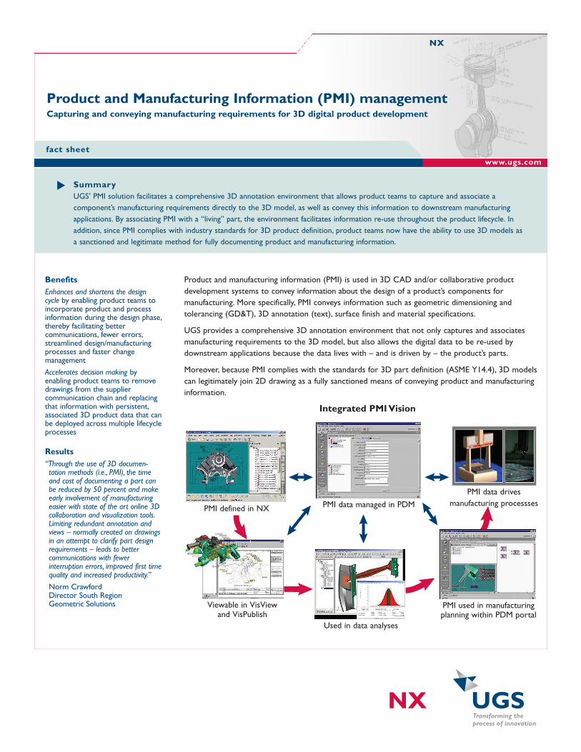
Integrated PMI Vision
PMI data managed in PDM
PMI data drivesmanufacturing processses
PMI used in manufacturingplanning within PDM portal
Used in data analyses
PMI defined in NX
Viewable in VisViewand VisPublish

Use casesReplacing the universal 2D drawing. People are familiar with 2D drawings and use them as a means oflegally defining a finished product. 2D drawings contain standard symbology that is universallyunderstood and interpreted.
However, in some cases, the existence of multiple, redundant data required to define a manufacturedpart can lead to deviations in the final 3D form.
Interpretation errors, duplication errors or revision inconsistencies can contribute to costly mistakesthat quickly translate into lower quality and productivity. As a result, while 2D drawings contain the“recipe” for manufacturing a part, the true manufacturing process requires both the 3D form and 2Dinformation to produce a correct part the first time.
The use of 2D drawings for the purpose of communicating downstream production requirements canalso add an unnecessary burden to the product development cycle. A simple change in the productdefinition not only requires updated 3D digital data, but also necessitates numerous engineeringchanges to all 2D documentation associated with the product. Since it takes time to maintain thisdocumentation, the lifecycle for implementing a product change grows with the extent of its associated 2D data.
By using the NX PMI solution to embed 2D informationdirectly within the 3D model, product teams have no need tocreate multiple, redundant data sets to define a given part.Instead, PMI allows product teams to capture and shareengineering requirements within the 3D model – therebypermitting full utilization of the design intent, eliminating theneed for 2D drawings and ensuring that the final productcomplies with its engineering specifications.
Improved productivity through 3D product definition. When created in a 3D CAD model and directlyassociated with objects in the part, PMI provides the following benefits:• Reduces cost by ensuring that design intent is completely captured and associated to the model.
Deducing and interpreting design intent from 2D information is no longer necessary• Reduces rework associated with inaccurate or incomplete manufacturing information• Reduces manufacturing errors encountered as a result of manual translations and enforces
“characteristic accountability” for the final product definition• Increases productivity and quality by documenting the information once and reusing it everywhere
(redundant data is no longer required for downstream applications)• Supports concurrent engineering by facilitating the documentation of models earlier in the design
process. Design collaboration teams no longer need to wait for the production of the drawing tocommunicate design requirements
Digitally stored information can be easily re-used by numerous downstream processes – from theautomated creation of 2D drawings to final inspection of the produced part.
fact sheet NX
FeaturesComprehensive set of 3Dannotation tools for capturingdimension, tolerance and productdefinition information
Direct derivation from UGS’ NX™
Drafting software interfaces –requires no significant learningcurve to begin using the application
Fully re-usable in NX Drafting;viewable in JT-enabled viewers andintegrated with UGS’ validationtools
Full API coverage provided for allPMI features via JT, PLMXML andthe NX Open APIs

In addition, because PMI is supported and published in thelightweight JT format, product teams can take advantage ofthe preferred method for visualizing data:• Directly from a CAD/CAM system• In a standalone 3D product visualization tool• In the portal viewer of a product data management
(PDM) system
PMI not only reduces the need to generate 2D drawings; italso enables downstream applications to directly accessthis information for automating tasks such as CNCprogramming, tolerance stack up analysis and CMM analysis. As a result, product teams have enterprise-wide access to the right data at the right time with the right amount of detail.
By understanding and communicating the values of 3D PMI throughout an enterprise – from engineeringdepartments to the manufacturing floor and out to the supplier base – manufacturers are able torealize productivity, quality and efficiency gains throughout their upstream and downstream processes.
PMI can contain GD&T, weld symbols, text and dimensions, as well as the product definition andprocess notes. PMI can exist in 3D models in the same way that information exists on 2D drawings –using leader lines that connect the data to specific parts in the product design. As a result, PMI providesan intuitive environment for users familiar with a 2D system.
Once PMI is created, it can be re-used thought the product lifecycle – from the engineering drawing tovalidation analysis, from visualization tools that facilitate collaboration and markup to manufacturing andquality planning processes. The essential value of PMI remains the same: Create it once, use it anywhere.
Packaging and availabilityPMI management tools are included with many NX Mach Series solution packages, and available as anadd-on module for earlier NX installations.
fact sheet NX
ContactUGSAmericas 800 498 5351Europe +44 (0) 1276 702000Asia-Pacific 852 2230 3333www.ugs.com
UGS, Transforming the process of innovation, Femap, Geolus, I-deas, JT, NX, Parasolid, Solid Edge, Teamcenter, Tecnomatix and Velocity Series are trademarks orregistered marks of UGS Corp. or its subsidiaries in the United States and in other countries. All other logos, trademarks, registered trademarks or servicemarks belong to their respective holders. ©2007 UGS Corp. All rights reserved. 1/07