Embed Size (px)
Citation preview

Brobo Group brobo.com.au
©
BROBO GROUP (AUST) PTY. LTD. 8 Fowler Rd, Dandenong South Victoria 3175, AUSTRALIA.
☏ + 61 3 9794 8751 📧 [email protected]
🖷 + 61 3 9794 8792 www.brobo.com.au
PRODUCT & MAINTENANCE MANUAL
SEMI-AUTOMATIC SAW
MODEL No. SA350, SA400
Precision Drilling Machines Tapping Machines Multi-Head Drills Tool Grinders
Tool Post Grinders Machine Vices Special Production Equipment
Accessories Riveting Machines Pedestal Grinders Metal Cutting Saws Linishers
YOUR BROBO DISTRIBUTOR IS:
A.C.N. 098 264 316 A.B.N. 42 098 264 316
Brobo Group brobo.com.au
OPERATING MANUAL FOR BROBO GROUP SEMI-AUTOMATIC (PLC CONTROLLED) CUTTING SAWS TECHNICAL SPECIFICATION CHAPTER 1: Installation of the Machine
1.1 Unpacking & Handling the Machine 1.2 Parts Checklist 1.3 Minimum Requirements 1.4 Anchoring the Saw 1.5 Connection to Power Source 1.6 Connection to Compressed Air Supply
CHAPTER 2: Safety & Accident Prevention
2.1 Operation of the Machine 2.1.1. Noise Level 2.1.2. Power Supply 2.1.3. Compressed Air Supply 2.2 General Requirements 2.3 Advice for the Operator 2.4 Machine Safety Devices 2.4.1. Reference Standards
CHAPTER 3: Main Functions & Operation of the Machine
3.1.1. Cutting Head 3.1.2. Saw Safety Guard 3.1.3. Saw Actuator 3.1.4. Pneumatic Vice Clamp 3.1.5. PLC Controlled Box 3.2 Preparation for Operation 3.3 Operation Recommendations
CHAPTER 4: Drawings, Layouts, Assembly & Spare Parts
4.1.1 Cold Saw Main Dimensions 4.1.2 Cold Saw Assembly 4.2.1 Standard Gearbox Assembly 4.2.2 Gearbox Assembly (400) 4.2.3 Coolant Tank Assembly 4.2.4 Motor Assembly 4.3.1 Pneumatic Vice Assembly 4.3.2 Pneumatic/Electrical Diagram 4.3.3 Broborule Series
CHAPTER 5: Adjustments to the Saw Unit 5.1 Changing the Blade 5.2 Adjusting the Cutting Angle 5.3 Cutting & Feeding Speeds 5.4 Refilling the Lubricator 5.5 Adjusting the Brobolube Unit 5.5.1 Lubricating Oil Precautions – Health Hazard Information
CHAPTER 6: Maintenance & Selection of Consumables
6.1 Role of the Operator 6.2 Maintenance Requirements 6.3 General Maintenance of Functioning Components
CHAPTER 7: Troubleshoot 7.1 Troubleshooting For Blade & Cutting Problems 7.2 General Troubleshooting
APPENDIX i. Hazard/Risk Assessment ii. Workplace Health & Safety Policy
Brobo Group brobo.com.au
TECHNICAL SPECIFICATION STANDARD BLADE SIZES
Outer Diameter ( mm) Thickness (mm) Bore Size (mm) Number of Teeth
315 2.5 40 160 350 () 2.5 40 180
400 3.0 40 220 TABLE 1. Standard Blade Sizes () Recommendation
BLADE SELECTION CHART
Material Outer
Diameter ( mm) Wall Thickness
(mm)
Blade Diameter ( mm) & Number of Teeth
315 350 400
HOLLOW CROSS-SECTION
20 1 320 350 400
2 240 280 340
3 180 220 240
40
1 320 250 400
2 220 260 280
3 160 180 200
4 140 160 180
50
1 320 350 400
2 220 280 300
3 180 200 220
4 160 180 200
5 140 160 180
80
1 300 320 360
2 200 220 240
3 200 200 220
4 160 180 180
5 140 160 180
100
1 300 300 340
2 220 200 220
3 200 180 180
4 160 140 160
5 140 120 140
120
1
300 340
2 200 220
3 180 180
4 160 160
5 120 140
SOLID SECTIONS
10
280 280 300
20 160 200 240
30 140 160 200
40 120 140 140
50 80 100 120
60 80 100 TABLE 2. Blade Selection Chart
NOTE - CHART GUIDE ONLY
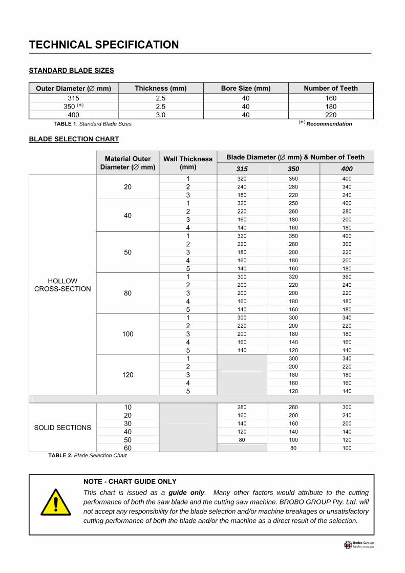
This chart is issued as a guide only. Many other factors would attribute to the cutting performance of both the saw blade and the cutting saw machine. BROBO GROUP Pty. Ltd. will not accept any responsibility for the blade selection and/or machine breakages or unsatisfactory cutting performance of both the blade and/or the machine as a direct result of the selection.
Brobo Group brobo.com.au
Blade Type: High-Speed Steel (HSS) 180 Tooth Blade ( 350mm x 40mm bore) Drive Pin Holes (Qty. PCD): SA350 2 8mm 55mm SA400 2 10.5mm 64mm MOTOR SPECIFICATIONS
1. CMG Motor 3 Phase/ 4 Poles/ IP55 /100L
V220-240 /50Hz/2.2 kW/1455 rpm V380-415 /50Hz/2.2 kW/1455 rpm V440-480 /60Hz/2.5 kW/1745 rpm
2. WEG Motor 3 Phase /4 Poles/ IP55 /100L V220-380 /50Hz/2.2 kW/1420 rpm V230-400 /50Hz/2.2 kW/1425 rpm V240-415 /50Hz/2.2 kW/1430 rpm V460/60Hz/2.5 kW/1735 rpm
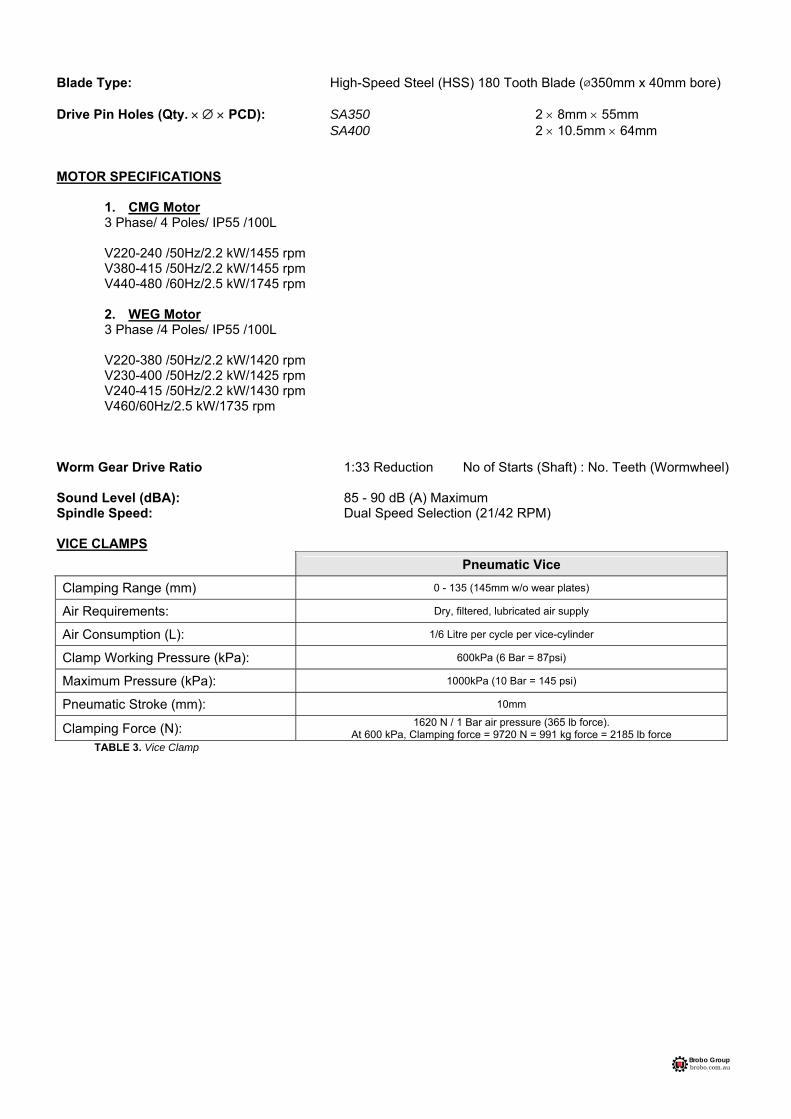
Worm Gear Drive Ratio 1:33 Reduction No of Starts (Shaft) : No. Teeth (Wormwheel) Sound Level (dBA): 85 - 90 dB (A) Maximum Spindle Speed: Dual Speed Selection (21/42 RPM) VICE CLAMPS
Pneumatic Vice
Clamping Range (mm) 0 - 135 (145mm w/o wear plates)
Air Requirements: Dry, filtered, lubricated air supply
Air Consumption (L): 1/6 Litre per cycle per vice-cylinder
Clamp Working Pressure (kPa): 600kPa (6 Bar = 87psi)
Maximum Pressure (kPa): 1000kPa (10 Bar = 145 psi)
Pneumatic Stroke (mm): 10mm
Clamping Force (N): 1620 N / 1 Bar air pressure (365 lb force). At 600 kPa, Clamping force = 9720 N = 991 kg force = 2185 lb force
TABLE 3. Vice Clamp

Brobo Group brobo.com.au
CUTTING RANGE
Cross-Sectional
Profile Angle
Cutting Range (mm)
SA350 SA400
90 115 4 4/8” 130 5 1/8”
45 110 4 3/8” 120 4 6/8”
90 100 100 3 7/8" 3 7/8" 110 110 4 3/8" 4 3/8"
45 85 85 3 3/8" 3 3/8" 95 95 3 6/8" 3 6/8"
90 85 135 3 3/8" 5 3/8" 100 135 3 7/8" 5 3/8"
45 85 95 3 3/8" 3 6/8" 100 95 3 7/8" 3 6/8"
Note: The above values are based on a full-size blade. The capacities will reduce accordingly when a worn blade is resharpened.
DIMENSIONAL SPECIFICATIONS Base Dimensions (L W): 550mm 660mm Table Working Height: 968 mm Saw Height: 1480 mm SAW WEIGHT Packaged SA350 278 kg SA400 280 kg
TABLE 4. Cutting Range
Brobo Group brobo.com.au
CHAPTER 1 - Installation of the Machine
1.1. Unpacking & Handling the Machine
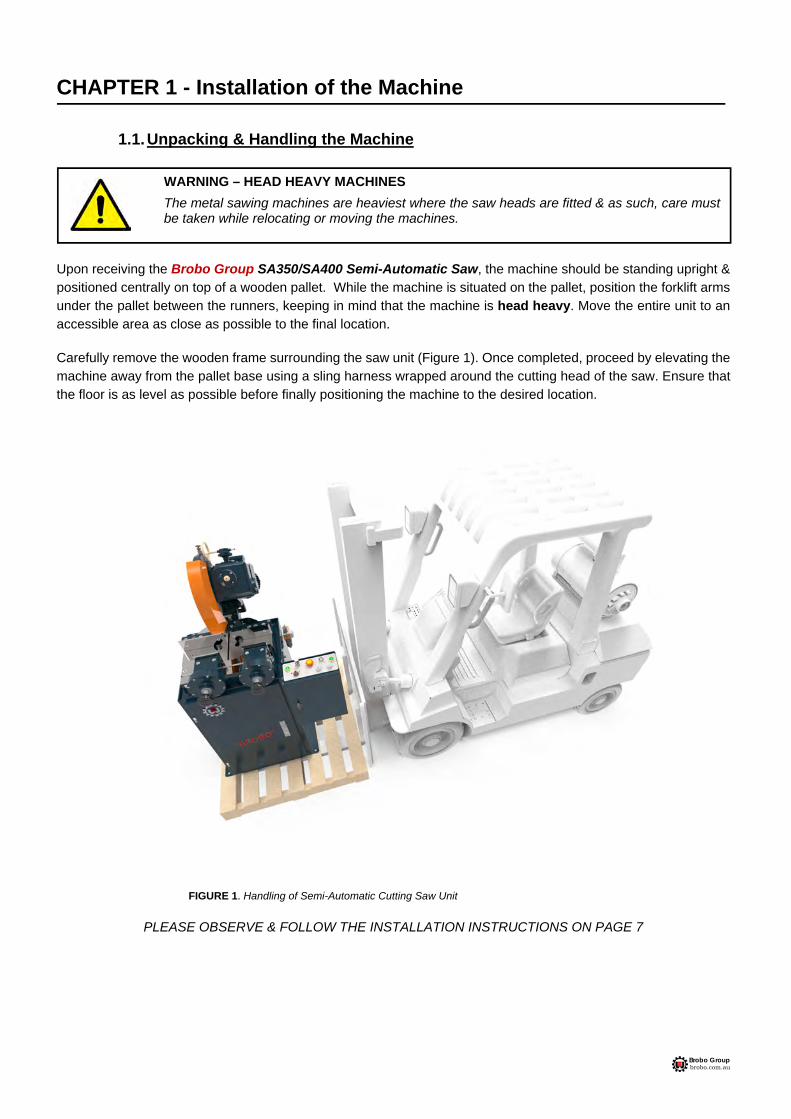
Upon receiving the Brobo Group SA350/SA400 Semi-Automatic Saw, the machine should be standing upright & positioned centrally on top of a wooden pallet. While the machine is situated on the pallet, position the forklift arms under the pallet between the runners, keeping in mind that the machine is head heavy. Move the entire unit to an accessible area as close as possible to the final location. Carefully remove the wooden frame surrounding the saw unit (Figure 1). Once completed, proceed by elevating the machine away from the pallet base using a sling harness wrapped around the cutting head of the saw. Ensure that the floor is as level as possible before finally positioning the machine to the desired location.
FIGURE 1. Handling of Semi-Automatic Cutting Saw Unit
PLEASE OBSERVE & FOLLOW THE INSTALLATION INSTRUCTIONS ON PAGE 7
WARNING – HEAD HEAVY MACHINES
The metal sawing machines are heaviest where the saw heads are fitted & as such, care must be taken while relocating or moving the machines.

Brobo Group brobo.com.au
1.2. Parts Checklist
Along with the saw unit, check that the following accessories, packed "loose", are included as follows:
A. STANDARD ACCESSORIES
1) 1 √ Saw Blade2) 1 √ Operating Handle3) 1 √ Service Kit (Hexagon wrenches 10mm & 14mm)4) 1 √ Operating Manual
B. OPTIONAL ACCESSORIES
Part Number Description
9311270 Standard Adjustable Length Stop (600mm)
9501450
9501470
‘Brobo-Rule’ Series Manual Micro-Adjustment Length Stop Available in 3.0m or 6.0m lengths
Field Kit includes rail, tape, micro-stop & extension arm.
9501210 Roller Conveyor
68 Kg Steel Rollers
3000mm x 305mm
150mm pitch
9501740 Fabricated Sheet Metal Stand
9301450 Floor Stand, Angle Iron
9501640 Brobolube
- Additional Blade(s) - Custom to Client Requirements
1.3. Minimum Requirements
For the machine to function correctly, the room in which the saw unit is to be installed must be in the vicinity of, & satisfy the following conditions:
240/415V Power Supply Working Pressure - Not less than 600kPa (6 Bar) & no greater than 900kPa (9 Bar)
Ambient Temperature - From -10C to +50C.
Relative Humidity: Not more than 90%. Lighting: More than 500 LUX.
WARNING – OPERATING VOLTAGE VARIATION
Each saw model has an inbuilt safety system to protect it against voltage variations. However, for the machine to perform efficiently, ensure that the saw unit operates within 10% limits of the recommended voltage of the motor.
Brobo Group brobo.com.au
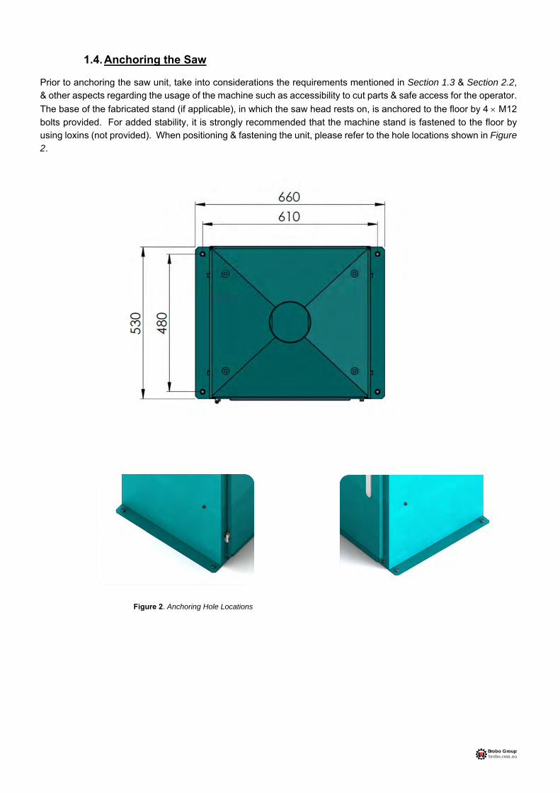
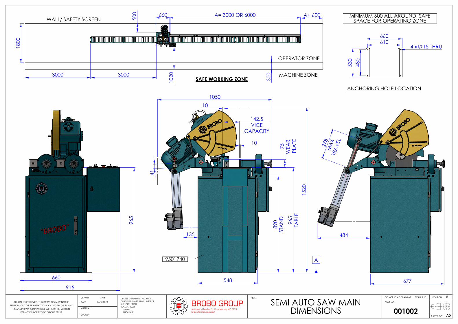
1.4. Anchoring the Saw Prior to anchoring the saw unit, take into considerations the requirements mentioned in Section 1.3 & Section 2.2, & other aspects regarding the usage of the machine such as accessibility to cut parts & safe access for the operator.
The base of the fabricated stand (if applicable), in which the saw head rests on, is anchored to the floor by 4 M12
bolts provided. For added stability, it is strongly recommended that the machine stand is fastened to the floor by using loxins (not provided). When positioning & fastening the unit, please refer to the hole locations shown in Figure 2.
Figure 2. Anchoring Hole Locations
Brobo Group brobo.com.au
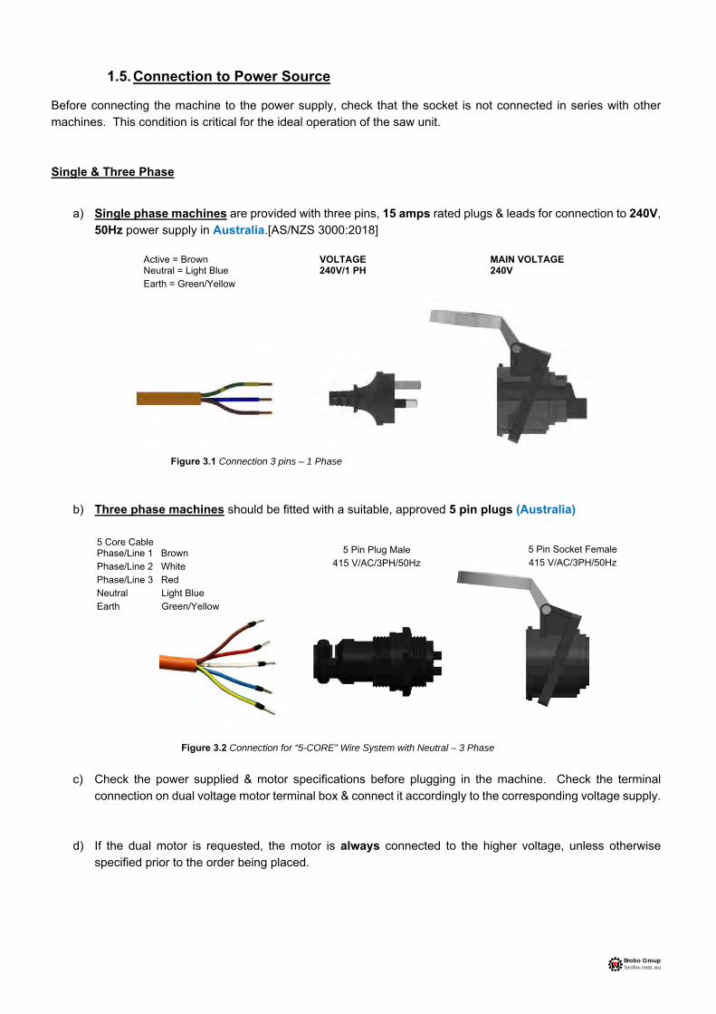
1.5. Connection to Power Source
Before connecting the machine to the power supply, check that the socket is not connected in series with other machines. This condition is critical for the ideal operation of the saw unit.
Single & Three Phase
a) Single phase machines are provided with three pins, 15 amps rated plugs & leads for connection to 240V,50Hz power supply in Australia.[AS/NZS 3000:2018]
Figure 3.1 Connection 3 pins – 1 Phase
b) Three phase machines should be fitted with a suitable, approved 5 pin plugs (Australia)
Figure 3.2 Connection for “5-CORE” Wire System with Neutral – 3 Phase
c) Check the power supplied & motor specifications before plugging in the machine. Check the terminalconnection on dual voltage motor terminal box & connect it accordingly to the corresponding voltage supply.
d) If the dual motor is requested, the motor is always connected to the higher voltage, unless otherwisespecified prior to the order being placed.
5 Core Cable Phase/Line 1 Brown Phase/Line 2 White Phase/Line 3 Red Neutral Light Blue Earth Green/Yellow
Active = Brown VOLTAGE MAIN VOLTAGE Neutral = Light Blue 240V/1 PH 240V Earth = Green/Yellow
5 Pin Plug Male 415 V/AC/3PH/50Hz
5 Pin Socket Female 415 V/AC/3PH/50Hz

Brobo Group brobo.com.au
To connect the machine to the power supply, proceed as follows:
1) Insert the power plug into the socket, while ensuring that the mains voltage is compatible for which the saw unit is operating.
2) Switch the saw on by rotating the control switch located on power switch assembly as shown in Figure 4 below.
Figure 4. Main Control Switch
3) Make sure that the saw is NOT currently in an emergency condition, whereby the EMERGENCY STOP button is depressed. If so, twist the red mushroom button until it is released & returned to the neutral state.
4) On first power-up, ensure that pneumatic vice is operating in a correct direction acting to release the piece
when the saw is not running & clamp what saw is running.
5) Check that the motor is operating in the correct direction, that is the blade is rotating downwards & into the direction of the vice clamps.
6) Ensure that all electrical leads & cables (including supply leads) are maintained in good condition & away from sharp objects. All leads should be replaced if cut, sliced or damaged in any way.
1.6. Connection to Compress Air Supply
To ensure the ideal operation & long service life, it is recommended that the semi-auto saw is connected to a compressed air system with similar characteristics shown in Figure 5 below.
Figure 5. Ideal Air Supply Connection
Brobo Group SA350/400 Semi-Automatic Saw is now ready for use. Chapter 3 provides a detailed description of the various features of the saw & its operating cycles

Brobo Group brobo.com.au
CHAPTER 2 - Safety & Accident Prevention The Brobo Group SA350/400 Semi-Automatic Saw has been designed & manufactured in accordance with Australian Standards. It is HIGHLY RECOMMENDED that the instructions & warnings contained in this chapter be carefully followed for correct usage of the machine.
2.1. Operation of the Machine The Brobo Group SA350/400 Semi-Automatic Saw is specifically designed to cut ferrous & non-ferrous metal cross sections with solid or thin-walled profiles. Other types of material & machining are not compatible for use with the specifications of the saw. This machine involves a high-speed blade rotation; therefore extreme caution is required when operating the device. The employer is responsible for instructing the personnel who, in turn, is obliged to inform the operator of any accident risks, safety devices, noise emission & accident prevention regulations provided for by national & international laws governing the use of the machine. The operator must be fully aware of the position & functions of all the machine’s controls. All those concerned must strictly adhere to ALL instructions, warnings & accident prevention standards in this manual. The following definitions are those provided for by the EEC DIRECTIVE ON MACHINERY No. 98/37/CE:
Danger Zone - any zone in and/or around a machine in which the presence of a person constitutes a risk to the safety & health of that person.
Person Exposed - any person finding him or herself, either completely or partly in a danger zone.
Operator - the person or persons are given the responsibility of installing, operating, adjusting, maintaining, cleaning, repairing, & transporting the machine.
2.1.1. Noise Level The noise level of an idling metal saw, fitted with a 180-tooth blade (supplied as standard by Brobo Group) has been measured to be below 85 dBA. This complies with the Australian Occupational Health and Safety (Noise) Regulations 1992. Please note that peak impulse noise levels will be experienced due to variables including blade characteristics, type, & condition. This will also vary accordingly depending on the size & type of sample being cut. Under these circumstances, management should make available to the operator(s) the appropriate hearing protection equipment as prescribed under the above-stated act.
WARNING – UNAUTHORISED MODIFICATIONS/REPLACEMENTS/USE
The manufacturer declines any responsibility whatsoever, either civil of criminal, in the case of unauthorised interference or replacement of one or more parts or assemblies on the machine, or if accessories, tools & consumable materials used are different from those recommended by the manufacturer, or if the machine is inserted in a plant system & its proper function is altered.

Brobo Group brobo.com.au
2.1.2. Power Supply
The 240/415V power supply requirements for this machine are of a high level & unauthorized interference & or inadequate maintenance could result in a situation that could put the operator at risk. A qualified electrical engineer should always be assigned to maintain & repair the system.
2.1.3. Compressed Air Supply
Various functions of the saw are carried out via the use of 6 bar compressed air. During these operations, situations would arise where machine parts & materials are clamped together & would potentially pose a serious safety issue to an inexperienced operator. Operators should be thoroughly instructed about these hazards. Only a qualified electrician should carry out regular maintenance of this system.
2.2. General Requirements
Lighting Insufficient lighting during the operation of the saw unit would constitute a safety hazard for the people concerned. For this reason, the user of the machine must provide adequate lighting in the working area to eliminate areas of shadow, whilst also preventing dazzling illumination sources (Reference standard ISO 8995 - 2002 ‘Lighting of Indoor Workplaces’). Connection Check that the power supply cables, compressed air supply (if applicable) & coolant system complies with, & are operating within the acceptable range of the saw capabilities. Faulty, damaged or worn components must be replaced immediately. Earthing Systems The installation of the earthing system must comply with the requirements stated in the: IEC Standards Part 195: Earthing & Protection Against Electric Shocks 1998. The position of the Operator The user controlling the machine saw operations must be positioned as shown in figure 6 below.
Figure 6. Correct Position for Operating Saw Unit

Brobo Group brobo.com.au
2.3. Advice for the Operator
Protective eyewear or goggles must be worn at all times while attending & operating the metal saw. Do not attempt to operate the machine unless all safety guards are in operation. The guard must fully cover the blade when the head is in the uppermost position. Ensure that hands & arms are kept clear of the cutting zone when the machine is operating. Do not wear loose clothing with long sleeves & oversized gloves, bracelets, necklaces or any other loose object that may become entangled in the machine’s blade during cutting. Long hair must be tied back or placed in a hair net. Always disconnect the power supply to the machine before carrying out any maintenance work or adjustments. This includes cases of abnormal operations of the machine. Any maintenance work performed on the hydraulic, pneumatic or coolant systems must be carried out only after the pressure in the system has been released. The operator MUST NOT conduct any risky operations or those not required for the cutting in course (e.g. remove swarf shavings from the machine while cutting). Never move the saw while the machine is operating. Always keep the workplace are as clean as possible. Remove equipment, tools or any other objects from the cutting zone. Support the workpiece on both sides of the machine to prevent it from falling or jamming during the cutting cycle.

Brobo Group brobo.com.au
Ensure that the specimen being cut is secured firmly in the vice clamps & the machine has been correctly set. Figure A show some examples of how to correctly clamp different specimen profiles. Before commencing the cut, be sure the vice(s) is securely clamped & the machine set-up is correct.
Figure A. Correct Clamping of Cutting Specimens
Do not use cutting blades of different sizes to those recommended to the machine’s specifications. Always follow safe practices & inspection procedures when installing blades (Please refer to section 5.1 Changing the Blade). When cutting very small specimens, ensure that the workpiece is not dragged behind the back fence support, where it could get lodged behind the blade. If the blade jams during a cut, activate the emergency stop function immediately. Do not continue forcing the blade through. This could damage the blade, the specimen or be a cause for potential injury to the operator. Always turn off the machine before carrying out any repair work. Consult the Brobo Group Engineering Department in the country in which the machine was initially purchased.

Brobo Group brobo.com.au
2.4. Machine Safety Devices This product & maintenance manual is not purely intended as a guide for the usage, operation & maintenance of the saw unit in a strict production environment; it is instead an instrument to providing information on how to use the machine correctly & safely. The following standards listed in section 2.4.1, which are applicable to the Brobo Group SA350/400 Semi-Automatic Saw, are those specified by the EEC Committee that governs the safety of machinery, health & safety at work, personal protection & safeguarding of the work environment. In addition, the saw also complies with the Australian Standards regarding the safeguarding & general requirements for electrical equipment.
2.4.1. Reference Standards MACHINE SAFETY
EEC Directive No. 98/37/CE - Machines Directive
EEC Directive No. 91/368 - 94/68 - Amends sections of EEC Directive No. 98/37/CE relating to machine safety
EEC Directive No. 73/23 - Low Voltage Directive
AS4024.1 - 1996 - Safeguarding of Machinery HEALTH & SAFETY AT WORK
AS3100 - 2002 - General Requirements for Electrical Equipment
OH. & S. 1995.81/1995 - Compliance References
EEC Directive No. 80/1107; 83/477; 86/188; 88/188; 88/642 - Protection of workers against risks caused by exposure to physical, chemical & biological agents in the workplace
EEC Directive No. 73/23 & Special EEC Directives No. 89/654; 89/655 - Improvements in health & safety at work
Brobo Group brobo.com.au
CHAPTER 3 - Main Functions & Operation of the Machine
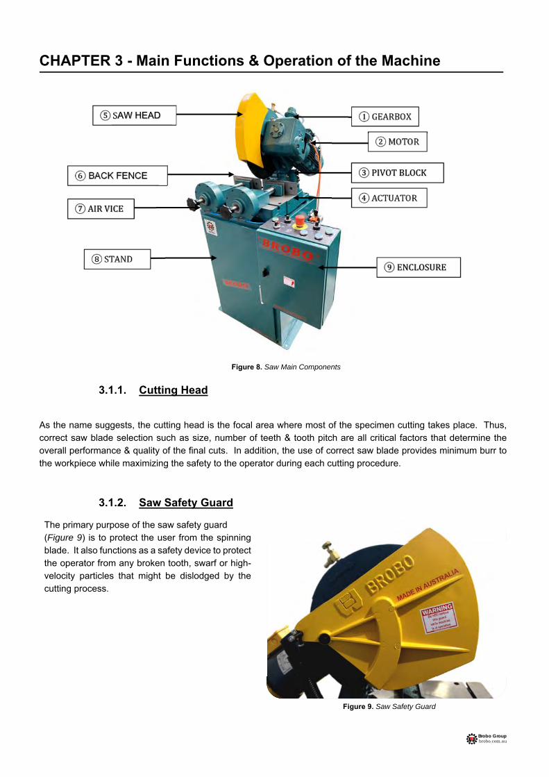
Figure 8. Saw Main Components
3.1.1. Cutting Head
As the name suggests, the cutting head is the focal area where most of the specimen cutting takes place. Thus, correct saw blade selection such as size, number of teeth & tooth pitch are all critical factors that determine the overall performance & quality of the final cuts. In addition, the use of correct saw blade provides minimum burr to the workpiece while maximizing the safety to the operator during each cutting procedure.
3.1.2. Saw Safety Guard The primary purpose of the saw safety guard (Figure 9) is to protect the user from the spinning blade. It also functions as a safety device to protect the operator from any broken tooth, swarf or high-velocity particles that might be dislodged by the cutting process.
Figure 9. Saw Safety Guard
AW HEAD
BACK FENCE

Brobo Group brobo.com.au
3.1.3. Saw Actuator The actuation unit (Figure 10) is a lead screw electric linear drive with special functions purpose-developed for cold cutting:
Auto cut-piece size detection & setting of saw stroke Constant force cutting Active Overload Feed Control
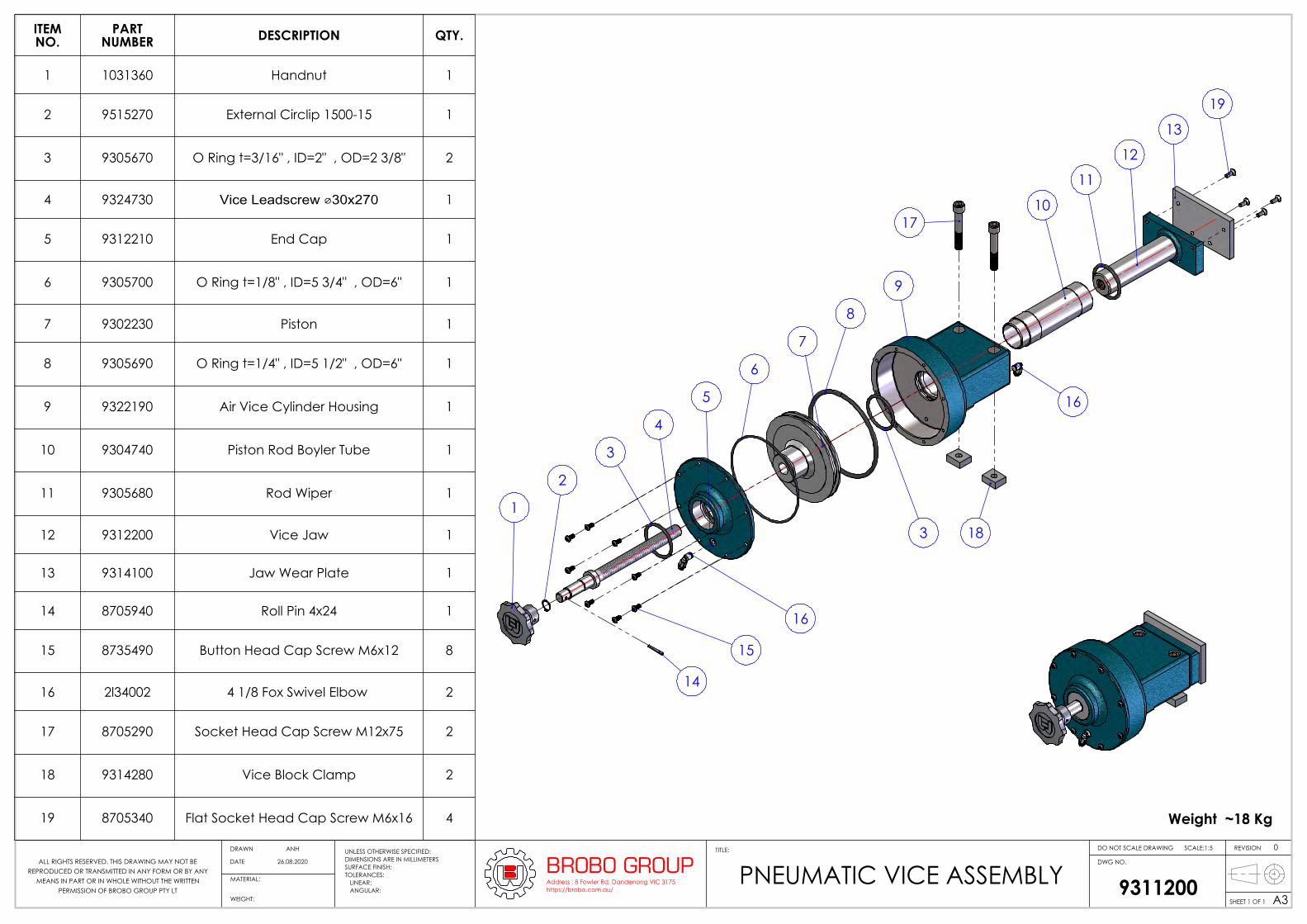
3.1.4. Pneumatic Vice Clamp
Operating at 600kPa, the vice clamps (Figure 11) firmly secure the workpiece in preparation for cutting. The pressure of each vice clamp could be modified using the pressure regulators located on the main electrical unit door. Each vice must be adjusted manually to accommodate various cross-sectional profiles.
Figure 10. Actuator
Figure 11. Pneumatic Vice Clamp
Brobo Group brobo.com.au
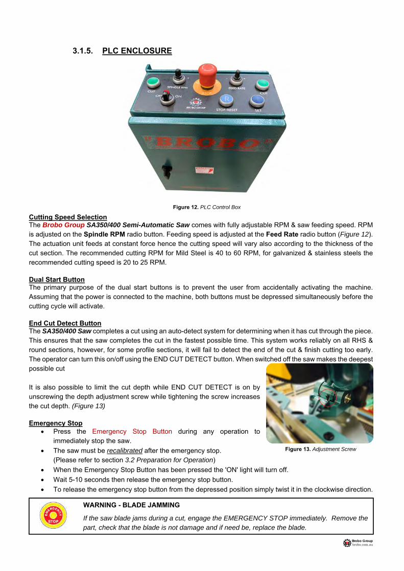
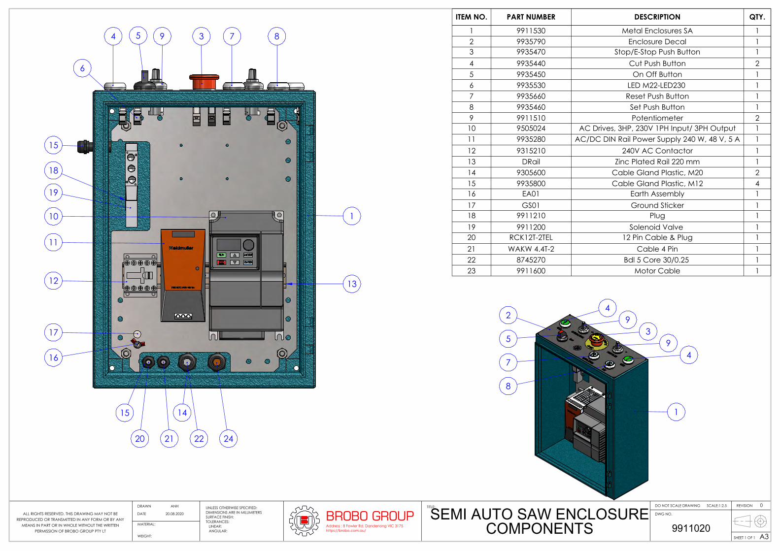
3.1.5. PLC ENCLOSURE
Cutting Speed Selection The Brobo Group SA350/400 Semi-Automatic Saw comes with fully adjustable RPM & saw feeding speed. RPM is adjusted on the Spindle RPM radio button. Feeding speed is adjusted at the Feed Rate radio button (Figure 12). The actuation unit feeds at constant force hence the cutting speed will vary also according to the thickness of the cut section. The recommended cutting RPM for Mild Steel is 40 to 60 RPM, for galvanized & stainless steels the recommended cutting speed is 20 to 25 RPM.
Dual Start Button The primary purpose of the dual start buttons is to prevent the user from accidentally activating the machine. Assuming that the power is connected to the machine, both buttons must be depressed simultaneously before the cutting cycle will activate. End Cut Detect Button The SA350/400 Saw completes a cut using an auto-detect system for determining when it has cut through the piece. This ensures that the saw completes the cut in the fastest possible time. This system works reliably on all RHS & round sections, however, for some profile sections, it will fail to detect the end of the cut & finish cutting too early. The operator can turn this on/off using the END CUT DETECT button. When switched off the saw makes the deepest possible cut It is also possible to limit the cut depth while END CUT DETECT is on by unscrewing the depth adjustment screw while tightening the screw increases the cut depth. (Figure 13) Emergency Stop
Press the Emergency Stop Button during any operation to immediately stop the saw.
The saw must be recalibrated after the emergency stop. (Please refer to section 3.2 Preparation for Operation)
When the Emergency Stop Button has been pressed the 'ON' light will turn off.
Wait 5-10 seconds then release the emergency stop button.
To release the emergency stop button from the depressed position simply twist it in the clockwise direction.
Figure 12. PLC Control Box
Figure 13. Adjustment Screw
WARNING - BLADE JAMMING
If the saw blade jams during a cut, engage the EMERGENCY STOP immediately. Remove the part, check that the blade is not damage and if need be, replace the blade.

Brobo Group brobo.com.au
3.2. Preparation for Operation
The following procedure is recommended for the correct cutting using the Brobo Group SA350/400 Semi-Automatic Saw
PROCEDURE
1. Cleaning Using a non-flammable & toxic free solvent, clean the machine to remove any corrosion protective coating prior to use.
2. Power On Ensure that both the air & electric power systems are turned on, where applicable. The electrical power source must be available before any pneumatic functions will operate.
3. Calibration
Upon power-up, the saw needs to be calibrated.
Immediately upon power-up pushing the STOP/RESET button will calibrate the saw. (Figure 14)
The saw will not respond to any other buttons until it is calibrated.
The saw calibrates by seeking both forward & back. The saw will first seek back, then forward, & MUST home forward against its base
Ensure there are no bars placed across the cutting area.
Once the saw touches the base it will go to the home position, briefly run the blade & wait for the next command.
4. Angle Adjustment
To adjust the angle of the cutting surface, if necessary, loosen the 2 bolts (Figure 15.) Fine-tune the angle required, then replace & re-tighten the 2 bolts.
5. Vice Clamp Setting Place the cutting specimen you wish to cut into the vice clamps. With a pneumatic vice, manually adjust the clamps so that the jaws are clamped firmly to the workpiece or with a clearance of 3 - 7mm. (Figure 16) (For correct clamping of material, please refer to section 2.3 Advice for the Operator).
Position the vice clamps & component as close to the blade as possible without interfering with the travel of the blade or guard. Vice relocation is required whenever the head angle is altered.
Figure 16. Clamp Clearance 3-7mm
Figure 14. Stop/Reset Button (Calibration)
Figure 15. Adjustment
WARNING - BLADE CHANGE
Calibration of the saw must be done after every blade change. Not doing so may result in the blade cutting into the base of the saw or actuator jamming. Ensure that the saw is turned off during blade changes.
WARNING – SAFETY GEAR
Protective clothing, safety glasses and gloves should always be worn while loading parts, operating the machine, or undertaking any maintenance work on the saw.

Brobo Group brobo.com.au
6. Vice Clamp Pressure
For pneumatic vices, set the vice clamping pressure from the pressure regulators located on the main control unit door. The vice clamps advance with an approximate 10mm pneumatic stroke to apply a clamping pressure of 6 bar (87 psi). If for any reason this pressure is not available on a continuous basis, the regulator on the air service unit must be set slightly below the available line pressure, & the safety low-pressure indicator valve needs to be reset to correspond with the newly available pressure. The need to change the pressure is necessary to allow for lighter materials with hollow cross sections to be cut without deforming the walls thicknesses.
7. SET Button
Once the workpiece & vices are in position press the SET button (Figure 17)
Vice jaws automatically close & apply clamping pressure.
The vices will clamp the piece & the saw will begin to seek the workpiece. Once the blade touches the workpiece it will rise slightly & then stop moving. At this point, the vice will release the piece. The saw is now ready to cut the workpiece.
8. CUT Button
When ready to cut, press the two CUT buttons simultaneously, (Figure 18)
The vices will clamp the workpiece, the blade will being to rotate & the saw will lower to cut the piece.
Once the cut is complete the vices will release the workpiece & the saw will return to the position set before the cut, ready to cut the same piece again.
To continue cutting this piece, simply place more tube in vice & press two CUT buttons simultaneously.
9. STOP/RESET BUTTON
When ready to cut a different sized piece or to stop the saw during any operation, simply press the STOP/RESET button. (Figure 19)
The saw will stop the current task immediately & return to the home position.
Figure 18. Dual Cut Button
Figure 17. Set Button
Figure 19. Stop/Reset Button
WARNING - BLADE MOTOR OVERLOAD
Saw is equipped with overload monitoring system which detects main motor overload in case of blade jam or inadvertent misuse. In case of overload saw reverses feed, re-establishes correct running of motor & continues the cut. If the saw overload system is reversing feed regularly during a cut, it indicates the blade is worn. Replace the blade promptly at this occurrence changes.

Brobo Group brobo.com.au
3.3. Operation Recommendations
Select the correct saw blade with the correct tooth pitch & form to suit the material to be cut to provide minimum burr & maximum blade lifespan.
o SA350 Blade Sizes 320-350 mm o SA400 Blade Sizes 350-400 mm
Use the smallest diameter blade & coarsest pitch that is practical within the required speed & material limitations.
Generally, use a tooth pitch to give 2 - 4 teeth engagement with the material during cutting.
Ensure that sufficient coolant is flowing over the cutting teeth.
Do not allow the machine’s gearbox to run idle in the upright position for more than 3 minutes otherwise, damage can occur to the drive system.
The rate of feed affects the quality of the final cut & blade life. This varies also by the material & cross-sectional dimensions. When cutting stainless steel or high carbon steel (Brinell hardness above 200), the slowest speed machine should be used together with a cobalt type high-speed steel blade.
As a rule of thumb the softer the component, the faster the rate of speed. Thus, it is recommended that slower speeds be used for hard & tough materials & higher speeds for soft, ductile materials. Note that for non-ferrous materials such as brass, copper, aluminium etc. require much faster speeds than provided on this machine. If these are the majority of materials cut, a Brobo NF Series machine should be considered.
CHAPTER 4 - Drawings, Layouts, Assembly & Spare Parts
890
ST
AN
D
965
TA
BLE
142.5 VICE
CAPACITY
10
10
75
WEA
R PL
ATE
41
548
1050
152
0
135
9501740 A
500
A+ 600 660
300
102
0 3000 3000
A= 3000 OR 6000 1
800
MACHINE ZONE
WALL/ SAFETY SCREEN
SAFE WORKING ZONE
OPERATOR ZONE
480
610 660
530
4 x 15 THRU
ANCHORING HOLE LOCATION
915
660
965
677
278
M
AX
TRA
VEL
484
MINIMUM 600 ALL AROUND SAFE SPACE FOR OPERATING ZONE
UNLESS OTHERWISE SPECIFIED:DIMENSIONS ARE IN MILLIMETERSSURFACE FINISH:TOLERANCES: LINEAR: ANGULAR:
MATERIAL:
DO NOT SCALE DRAWING REVISIONTITLE:
DWG NO.
SCALE:1:10
SHEET 1 OF 1 A3WEIGHT: 001002
SEMI AUTO SAW MAIN DIMENSIONS
BROBO GROUPAddress : 8 Fowler Rd, Dandenong VIC 3175https://brobo.com.au/
06.10.2020
0DRAWN
DATE
ANH
ALL RIGHTS RESERVED. THIS DRAWING MAY NOT BE REPRODUCED OR TRANSMITTED IN ANY FORM OR BY ANY
MEANS IN PART OR IN WHOLE WITHOUT THE WRITTEN PERMISSION OF BROBO GROUP PTY LT
1
32
4
12
6
78
9
13
14
15
36
30
2316 17
29
31
2526 2428
5
27
32
10
11
35 34 33
37
182119 20
42
40
39
3843
44
45
41
43
48
55
54
47
5250
5149
53
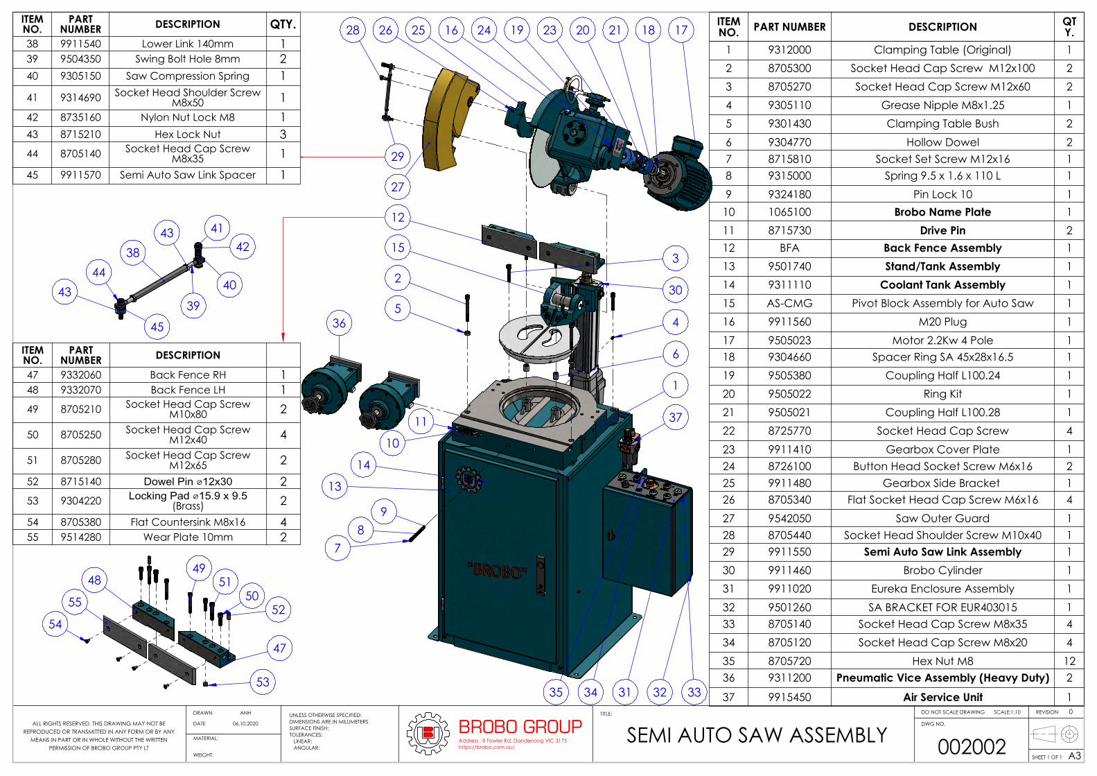
ITEM NO. PART NUMBER DESCRIPTION QT
Y.1 9312000 Clamping Table (Original) 12 8705300 Socket Head Cap Screw M12x100 23 8705270 Socket Head Cap Screw M12x60 24 9305110 Grease Nipple M8x1.25 15 9301430 Clamping Table Bush 26 9304770 Hollow Dowel 27 8715810 Socket Set Screw M12x16 18 9315000 Spring 9.5 x 1.6 x 110 L 19 9324180 Pin Lock 10 110 1065100 Brobo Name Plate 111 8715730 Drive Pin 212 BFA Back Fence Assembly 113 9501740 Stand/Tank Assembly 114 9311110 Coolant Tank Assembly 115 AS-CMG Pivot Block Assembly for Auto Saw 116 9911560 M20 Plug 117 9505023 Motor 2.2Kw 4 Pole 118 9304660 Spacer Ring SA 45x28x16.5 119 9505380 Coupling Half L100.24 120 9505022 Ring Kit 121 9505021 Coupling Half L100.28 122 8725770 Socket Head Cap Screw 423 9911410 Gearbox Cover Plate 124 8726100 Button Head Socket Screw M6x16 225 9911480 Gearbox Side Bracket 126 8705340 Flat Socket Head Cap Screw M6x16 427 9542050 Saw Outer Guard 128 8705440 Socket Head Shoulder Screw M10x40 129 9911550 Semi Auto Saw Link Assembly 130 9911460 Brobo Cylinder 131 9911020 Eureka Enclosure Assembly 132 9501260 SA BRACKET FOR EUR403015 133 8705140 Socket Head Cap Screw M8x35 434 8705120 Socket Head Cap Screw M8x20 435 8705720 Hex Nut M8 1236 9311200 Pneumatic Vice Assembly (Heavy Duty) 2
37 9915450 Air Service Unit 1
ITEM NO.
PART NUMBER DESCRIPTION QTY.
38 9911540 Lower Link 140mm 139 9504350 Swing Bolt Hole 8mm 240 9305150 Saw Compression Spring 1
41 9314690 Socket Head Shoulder Screw M8x50 1
42 8735160 Nylon Nut Lock M8 143 8715210 Hex Lock Nut 344 8705140 Socket Head Cap Screw
M8x35 145 9911570 Semi Auto Saw Link Spacer 1
ITEM NO.
PART NUMBER DESCRIPTION
47 9332060 Back Fence RH 148 9332070 Back Fence LH 149 8705210 Socket Head Cap Screw
M10x80 2
50 8705250 Socket Head Cap Screw M12x40 4
51 8705280 Socket Head Cap Screw M12x65 2
52 8715140 Dowel Pin ⌀12x30 253 9304220 Locking Pad ⌀15.9 x 9.5
(Brass) 254 8705380 Flat Countersink M8x16 455 9514280 Wear Plate 10mm 2
UNLESS OTHERWISE SPECIFIED:DIMENSIONS ARE IN MILLIMETERSSURFACE FINISH:TOLERANCES: LINEAR: ANGULAR:
MATERIAL:
DO NOT SCALE DRAWING REVISIONTITLE:
DWG NO.
SCALE:1:10
SHEET 1 OF 1 A3WEIGHT: 002002SEMI AUTO SAW ASSEMBLYBROBO GROUPAddress : 8 Fowler Rd, Dandenong VIC 3175https://brobo.com.au/
06.10.2020
0DRAWN
DATE
ANH
ALL RIGHTS RESERVED. THIS DRAWING MAY NOT BE REPRODUCED OR TRANSMITTED IN ANY FORM OR BY ANY
MEANS IN PART OR IN WHOLE WITHOUT THE WRITTEN PERMISSION OF BROBO GROUP PTY LT

3
4
5
6
7
9
8
1
2
10
11
12
18
21
19
20
16131415
2324
2526
2728
29
17
30
HEX HEAD
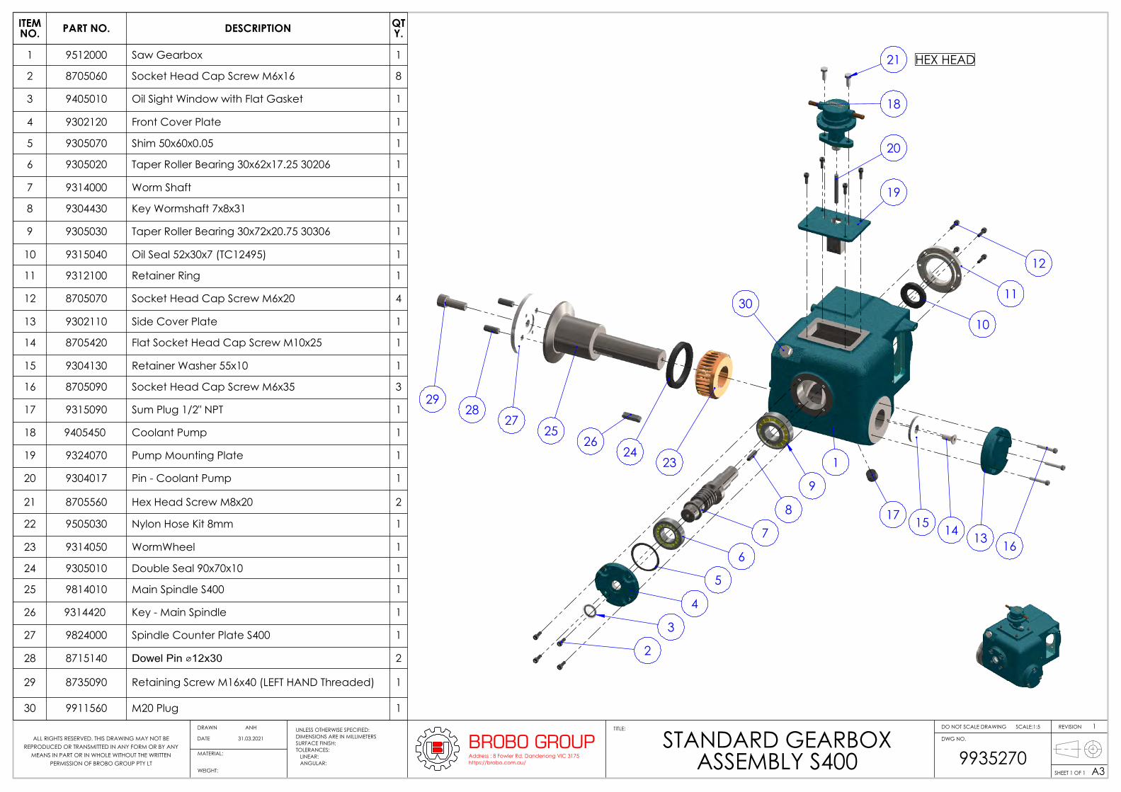
ITEM NO. PART NUMBER DESCRIPTION QTY.
1 9512000 Saw Gearbox 1
2 8705060 Socket Head Cap Screw M6x16 8
3 9405010 Oil Sight Window with Flat Gasket 1
4 9302120 Front Cover Plate 1
5 9305070 Shim 50x60x0.05 1
6 9305020 Taper Roller Bearing 30x62x17.25 30206 1
7 9314000 Worm Shaft 1
8 9304430 Key Wormshaft 7x8x31 1
9 9305030 Taper Roller Bearing 30x72x20.75 30306 1
10 9315040 Oil Seal 52x30x7 (TC12495) 1
11 9312100 Retainer Ring 1
12 8705070 Socket Head Cap Screw M6x20 4
13 9302110 Side Cover Plate 1
14 8705420 Flat Socket Head Cap Screw M10x25 1
15 9304130 Retainer Washer 55x10 1
16 8705090 Socket Head Cap Screw M6x35 3
17 9315090 Sum Plug 1/2" NPT 1
18 9405450 Coolant Pump 1
19 9324070 Pump Mounting Plate 1
20 9304017 Pin - Coolant Pump 1
21 8705560 Hex Head Screw M8x20 2
22 9505030 Nylon Hose Kit 8mm 1
23 9314050 WormWheel 1
24 9305010 Double Seal 90x70x10 1
25 9504080 Main Spindle S315.S350 1
26 9314420 Key - Main Spindle 1
27 9504090 Spindle Counter Plate (S315D, S350D) 1
28 8715080 Dowel Pin 8x25 2
29 8735090 Retaining Screw M16x40 (LEFT HAND Threaded) 1
30 9911560 M20 Plug 1
UNLESS OTHERWISE SPECIFIED:DIMENSIONS ARE IN MILLIMETERSSURFACE FINISH:TOLERANCES: LINEAR: ANGULAR:
MATERIAL:
DO NOT SCALE DRAWING REVISIONTITLE:
DWG NO.
SCALE:1:5
SHEET 1 OF 1 A3WEIGHT: 9935260
STANDARD GEARBOXASSEMBLY S350
BROBO GROUPAddress : 8 Fowler Rd, Dandenong VIC 3175https://brobo.com.au/
31.03.2021
1DRAWN
DATE
ANH
ALL RIGHTS RESERVED. THIS DRAWING MAY NOT BE REPRODUCED OR TRANSMITTED IN ANY FORM OR BY ANY
MEANS IN PART OR IN WHOLE WITHOUT THE WRITTEN PERMISSION OF BROBO GROUP PTY LT
3
4
5
6
7
9
8
1
2
10
11
12
18
21
19
20
1613141517
2324
2526
2729
28
30
HEX HEAD
ITEM NO. PART NO. DESCRIPTION QT
Y.
1 9512000 Saw Gearbox 1
2 8705060 Socket Head Cap Screw M6x16 8
3 9405010 Oil Sight Window with Flat Gasket 1
4 9302120 Front Cover Plate 1
5 9305070 Shim 50x60x0.05 1
6 9305020 Taper Roller Bearing 30x62x17.25 30206 1
7 9314000 Worm Shaft 1
8 9304430 Key Wormshaft 7x8x31 1
9 9305030 Taper Roller Bearing 30x72x20.75 30306 1
10 9315040 Oil Seal 52x30x7 (TC12495) 1
11 9312100 Retainer Ring 1
12 8705070 Socket Head Cap Screw M6x20 4
13 9302110 Side Cover Plate 1
14 8705420 Flat Socket Head Cap Screw M10x25 1
15 9304130 Retainer Washer 55x10 1
16 8705090 Socket Head Cap Screw M6x35 3
17 9315090 Sum Plug 1/2" NPT 1
18 9405450 Coolant Pump 1
19 9324070 Pump Mounting Plate 1
20 9304017 Pin - Coolant Pump 1
21 8705560 Hex Head Screw M8x20 2
22 9505030 Nylon Hose Kit 8mm 1
23 9314050 WormWheel 1
24 9305010 Double Seal 90x70x10 1
25 9814010 Main Spindle S400 1
26 9314420 Key - Main Spindle 1
27 9824000 Spindle Counter Plate S400 1
28 8715140 Dowel Pin ⌀12x30 2
29 8735090 Retaining Screw M16x40 (LEFT HAND Threaded) 1
30 9911560 M20 Plug 1
UNLESS OTHERWISE SPECIFIED:DIMENSIONS ARE IN MILLIMETERSSURFACE FINISH:TOLERANCES: LINEAR: ANGULAR:
MATERIAL:
DO NOT SCALE DRAWING REVISIONTITLE:
DWG NO.
SCALE:1:5
SHEET 1 OF 1 A3WEIGHT: 9935270
STANDARD GEARBOXASSEMBLY S400
BROBO GROUPAddress : 8 Fowler Rd, Dandenong VIC 3175https://brobo.com.au/
31.03.2021
1DRAWN
DATE
ANH
ALL RIGHTS RESERVED. THIS DRAWING MAY NOT BE REPRODUCED OR TRANSMITTED IN ANY FORM OR BY ANY
MEANS IN PART OR IN WHOLE WITHOUT THE WRITTEN PERMISSION OF BROBO GROUP PTY LT
1
2
4
3
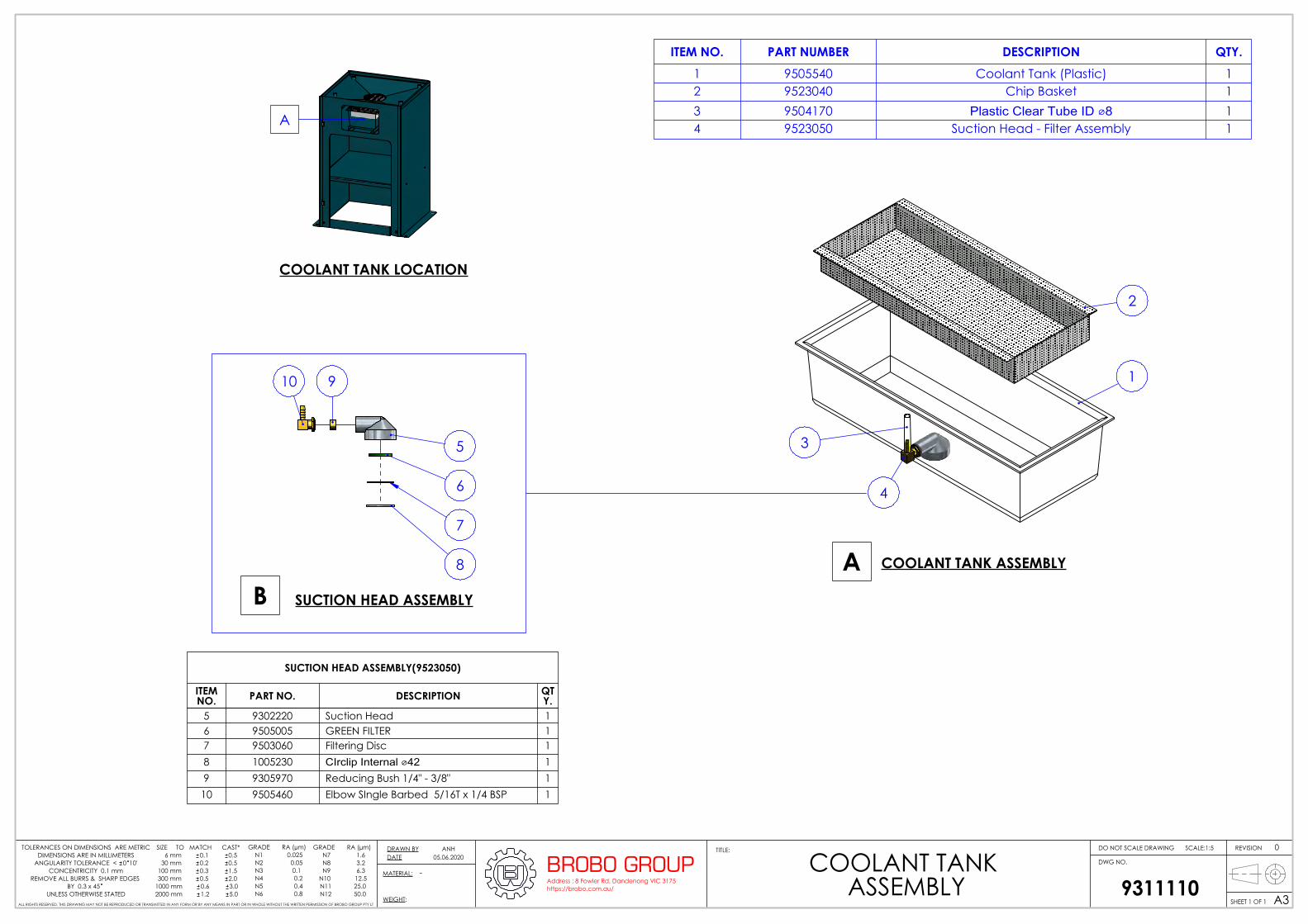
COOLANT TANK ASSEMBLYA
COOLANT TANK LOCATION
A
8
7
6
5
10 9
SUCTION HEAD ASSEMBLYB
SUCTION HEAD ASSEMBLY(9523050)
ITEM NO. PART NO. DESCRIPTION QT
Y.5 9302220 Suction Head 16 9505005 GREEN FILTER 17 9503060 Filtering Disc 18 1005230 CIrclip Internal ⌀42 19 9305970 Reducing Bush 1/4" - 3/8" 110 9505460 Elbow SIngle Barbed 5/16T x 1/4 BSP 1
ITEM NO. PART NUMBER DESCRIPTION QTY.1 9505540 Coolant Tank (Plastic) 12 9523040 Chip Basket 13 9504170 Plastic Clear Tube ID ⌀8 14 9523050 Suction Head - Filter Assembly 1
MATERIAL:
DO NOT SCALE DRAWING REVISIONTITLE:
DWG NO.
SCALE:1:5
SHEET 1 OF 1 A3WEIGHT: 9311110
COOLANT TANK ASSEMBLY
BROBO GROUPAddress : 8 Fowler Rd, Dandenong VIC 3175https://brobo.com.au/
05.06.20200DRAWN BY
DATEANH
ALL RIGHTS RESERVED. THIS DRAWING MAY NOT BE REPRODUCED OR TRANSMITTED IN ANY FORM OR BY ANY MEANS IN PART OR IN WHOLE WITHOUT THE WRITTEN PERMISSION OF BROBO GROUP PTY LT
SIZE TO MATCH CAST* 6 mm 0.1 0.5 30 mm 0.2 0.5 100 mm 0.3 1.5 300 mm 0.5 2.01000 mm 0.6 3.02000 mm 1.2 5.0
GRADE RA (µm) N1 0.025 N2 0.05 N3 0.1 N4 0.2 N5 0.4 N6 0.8
GRADE RA (µm) N7 1.6 N8 3.2 N9 6.3 N10 12.5 N11 25.0 N12 50.0
TOLERANCES ON DIMENSIONS ARE METRICDIMENSIONS ARE IN MILLIMETERS
ANGULARITY TOLERANCE < 0 10'CONCENTRICITY 0.1 mm
REMOVE ALL BURRS & SHARP EDGES BY 0.3 x 45
UNLESS OTHERWISE STATED
-

1
2
4
3
10
12
13
11
5
7
7
8
6
480 610
14
18
17
15
19
9503130
570
465
670
9301720
STAND ANGLE IRON(OPTIONAL)
ITEM NO. PART NUMBER DESCRIPTION QTY.1 9503130 Sheetmetal Stand 12 9503150 Saw Stand Shelf 13 9503160 Stand Brace 14 9503130.C08 Cover 15 8705120 Socket Head Cap Screw M8x20 26 8705720 Hex Nut M8 27 8705060 Socket Head Cap Screw M6x16 68 8705750 Hex Nut M6 69 9505017 Hinge 2
10 9503140 Saw Stand Door 111 9505016 Saw Stand Swing Handle (Latch Included) 112 8115080 Brobo Logo 65 113 9505018 "BROBO" Large 1
9503130 SHEETMETAL STANDITEM NO. PART NUMBER DESCRIPTION QTY.
14 9503130.C01 Front 115 9503130.C02 Back 116 9503130.C03 Top 117 9503130.C04 Rod 418 9503130.C05 Bended Equal Angle 1.6x50x515 219 9503150 Saw Stand Shelf 1
UNLESS OTHERWISE SPECIFIED:DIMENSIONS ARE IN MILLIMETERSSURFACE FINISH:TOLERANCES: LINEAR: ANGULAR:
MATERIAL:
DO NOT SCALE DRAWING REVISIONTITLE:
DWG NO.
SCALE:1:10
SHEET 1 OF 1 A3WEIGHT: 9501740
BROBO STANDARD STANDASSEMBLY
BROBO GROUPAddress : 8 Fowler Rd, Dandenong VIC 3175https://brobo.com.au/
15.05.2020
0DRAWN
DATE
ANH
ALL RIGHTS RESERVED. THIS DRAWING MAY NOT BE REPRODUCED OR TRANSMITTED IN ANY FORM OR BY ANY
MEANS IN PART OR IN WHOLE WITHOUT THE WRITTEN PERMISSION OF BROBO GROUP PTY LT
1918
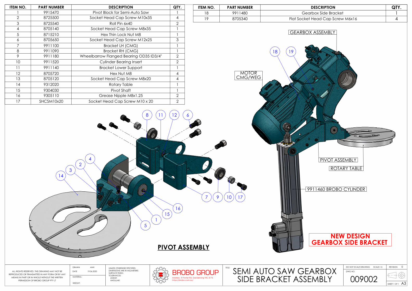
PIVOT ASSEMBLY
GEARBOX ASSEMBLY
9911460 BROBO CYLINDER
MOTORCMG/WEG
ROTARY TABLE
NEW DESIGNGEARBOX SIDE BRACKET
PIVOT ASSEMBLY
1
23
4
5
7
8 11 12
9 10 17
6
14
1516
ITEM NO. PART NUMBER DESCRIPTION QTY.18 9911480 Gearbox Side Bracket 119 8705340 Flat Socket Head Cap Screw M6x16 4
ITEM NO. PART NUMBER DESCRIPTION QTY.1 9915470 Pivot Block for Semi-Auto Saw 12 8725500 Socket Head Cap Screw M10x35 43 8725540 Roll Pin 6x40 24 8705140 Socket Head Cap Screw M8x35 15 8715210 Hex Thin Lock Nut M8 16 8705650 Socket Head Cap Screw M12x25 37 9911100 Bracket LH (CMG) 18 9911090 Bracket RH (CMG) 19 9911180 Wheelbarrow Flanged Bearing OD35 ID3/4" 210 9911520 Cylinder Bearing Insert 211 9911140 Bracket Lower Support 112 8705720 Hex Nut M8 413 8705120 Socket Head Cap Screw M8x20 414 9312020 Rotary Table 115 9304030 Pivot Shaft 116 9305110 Grease Nipple M8x1.25 217 SHCSM10x20 Socket Head Cap Screw M10 x 20 2
UNLESS OTHERWISE SPECIFIED:DIMENSIONS ARE IN MILLIMETERSSURFACE FINISH:TOLERANCES: LINEAR: ANGULAR:
MATERIAL:
DO NOT SCALE DRAWING REVISIONTITLE:
DWG NO.
SCALE:1:5
SHEET 1 OF 1 A3WEIGHT: 009002
SEMI AUTO SAW GEARBOX SIDE BRACKET ASSEMBLY
BROBO GROUPAddress : 8 Fowler Rd, Dandenong VIC 3175https://brobo.com.au/
19.06.2020
0DRAWN
DATE
ANH
ALL RIGHTS RESERVED. THIS DRAWING MAY NOT BE REPRODUCED OR TRANSMITTED IN ANY FORM OR BY ANY
MEANS IN PART OR IN WHOLE WITHOUT THE WRITTEN PERMISSION OF BROBO GROUP PTY LT
78
6
13
5
2
3
1112
4
10
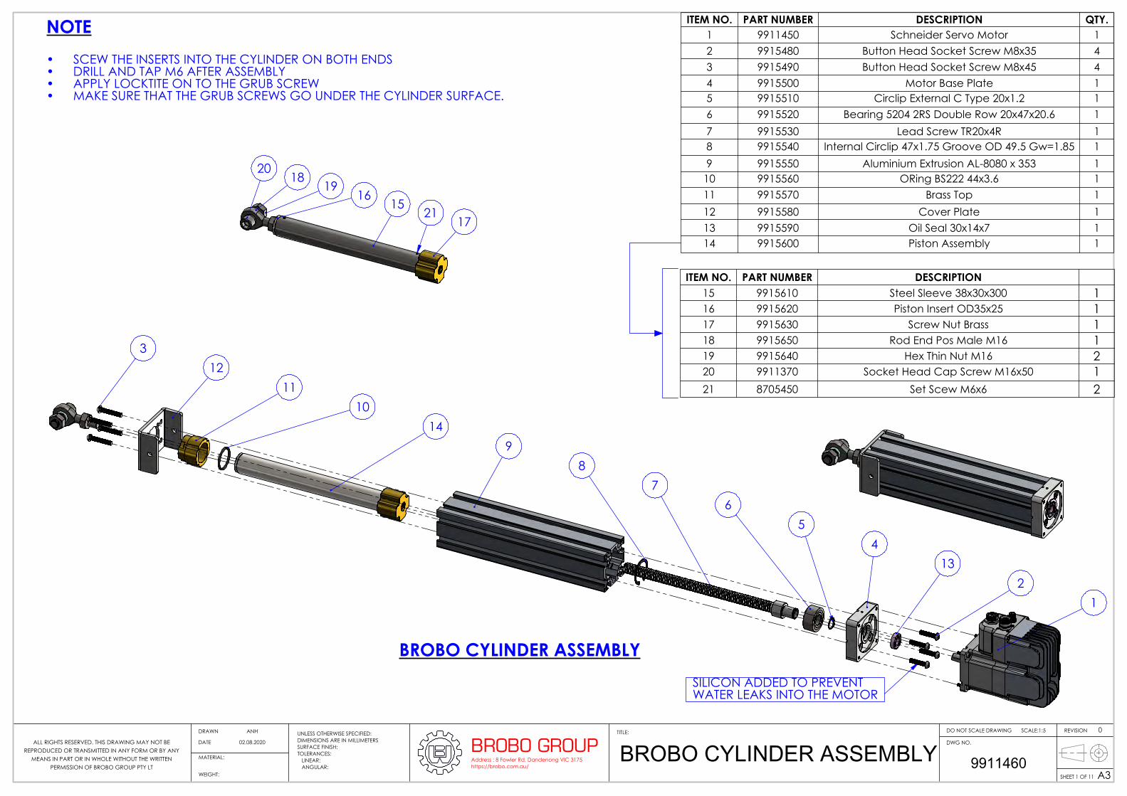
BROBO CYLINDER ASSEMBLYSILICON ADDED TO PREVENT WATER LEAKS INTO THE MOTOR
14
1
9
1521
16
17
1918
20
NOTESCEW THE INSERTS INTO THE CYLINDER ON BOTH ENDS•DRILL AND TAP M6 AFTER ASSEMBLY•APPLY LOCKTITE ON TO THE GRUB SCREW•MAKE SURE THAT THE GRUB SCREWS GO UNDER THE CYLINDER SURFACE.•
ITEM NO. PART NUMBER DESCRIPTION QTY.1 9911450 Schneider Servo Motor 12 9915480 Button Head Socket Screw M8x35 43 9915490 Button Head Socket Screw M8x45 44 9915500 Motor Base Plate 15 9915510 Circlip External C Type 20x1.2 16 9915520 Bearing 5204 2RS Double Row 20x47x20.6 17 9915530 Lead Screw TR20x4R 18 9915540 Internal Circlip 47x1.75 Groove OD 49.5 Gw=1.85 19 9915550 Aluminium Extrusion AL-8080 x 353 1
10 9915560 ORing BS222 44x3.6 111 9915570 Brass Top 112 9915580 Cover Plate 113 9915590 Oil Seal 30x14x7 114 9915600 Piston Assembly 1
ITEM NO. PART NUMBER DESCRIPTION15 9915610 Steel Sleeve 38x30x300 116 9915620 Piston Insert OD35x25 117 9915630 Screw Nut Brass 118 9915650 Rod End Pos Male M16 119 9915640 Hex Thin Nut M16 220 9911370 Socket Head Cap Screw M16x50 121 8705450 Set Scew M6x6 2
UNLESS OTHERWISE SPECIFIED:DIMENSIONS ARE IN MILLIMETERSSURFACE FINISH:TOLERANCES: LINEAR: ANGULAR:
MATERIAL:
DO NOT SCALE DRAWING REVISIONTITLE:
DWG NO.
SCALE:1:5
SHEET 1 OF 11 A3WEIGHT: 9911460BROBO CYLINDER ASSEMBLYBROBO GROUP
Address : 8 Fowler Rd, Dandenong VIC 3175https://brobo.com.au/
02.08.2020
0DRAWN
DATE
ANH
ALL RIGHTS RESERVED. THIS DRAWING MAY NOT BE REPRODUCED OR TRANSMITTED IN ANY FORM OR BY ANY
MEANS IN PART OR IN WHOLE WITHOUT THE WRITTEN PERMISSION OF BROBO GROUP PTY LT
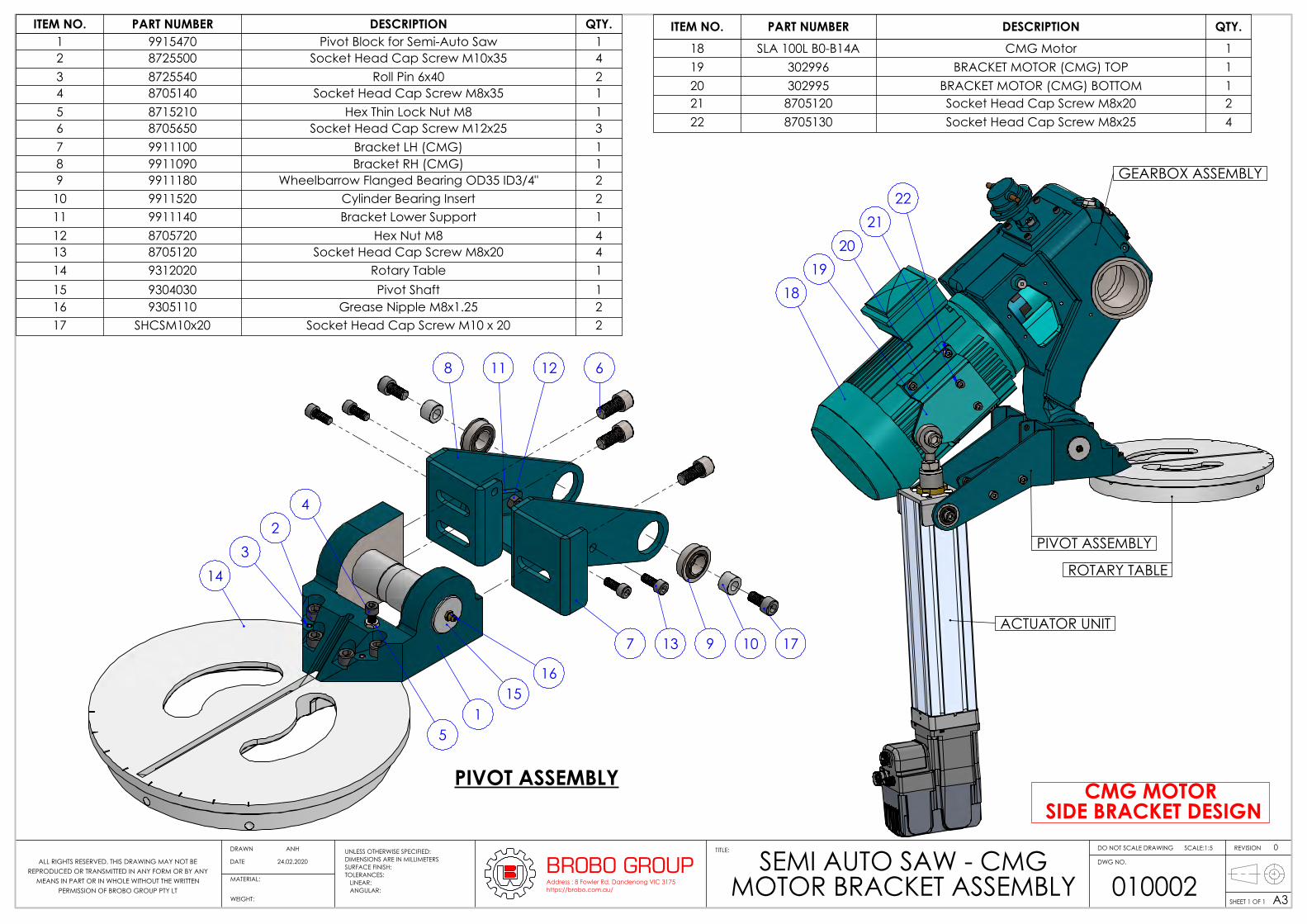
PIVOT ASSEMBLY
GEARBOX ASSEMBLY
ACTUATOR UNIT
ROTARY TABLE
1819
20
2221
CMG MOTOR SIDE BRACKET DESIGN
PIVOT ASSEMBLY
1
23
4
5
7
8 11 12
9 10 17
6
14
1516
13
ITEM NO. PART NUMBER DESCRIPTION QTY.1 9915470 Pivot Block for Semi-Auto Saw 12 8725500 Socket Head Cap Screw M10x35 43 8725540 Roll Pin 6x40 24 8705140 Socket Head Cap Screw M8x35 15 8715210 Hex Thin Lock Nut M8 16 8705650 Socket Head Cap Screw M12x25 37 9911100 Bracket LH (CMG) 18 9911090 Bracket RH (CMG) 19 9911180 Wheelbarrow Flanged Bearing OD35 ID3/4" 2
10 9911520 Cylinder Bearing Insert 211 9911140 Bracket Lower Support 112 8705720 Hex Nut M8 413 8705120 Socket Head Cap Screw M8x20 414 9312020 Rotary Table 115 9304030 Pivot Shaft 116 9305110 Grease Nipple M8x1.25 217 SHCSM10x20 Socket Head Cap Screw M10 x 20 2
ITEM NO. PART NUMBER DESCRIPTION QTY.18 SLA 100L B0-B14A CMG Motor 119 302996 BRACKET MOTOR (CMG) TOP 120 302995 BRACKET MOTOR (CMG) BOTTOM 121 8705120 Socket Head Cap Screw M8x20 222 8705130 Socket Head Cap Screw M8x25 4
UNLESS OTHERWISE SPECIFIED:DIMENSIONS ARE IN MILLIMETERSSURFACE FINISH:TOLERANCES: LINEAR: ANGULAR:
MATERIAL:
DO NOT SCALE DRAWING REVISIONTITLE:
DWG NO.
SCALE:1:5
SHEET 1 OF 1 A3WEIGHT: 010002
SEMI AUTO SAW - CMG MOTOR BRACKET ASSEMBLY
BROBO GROUPAddress : 8 Fowler Rd, Dandenong VIC 3175https://brobo.com.au/
24.02.2020
0DRAWN
DATE
ANH
ALL RIGHTS RESERVED. THIS DRAWING MAY NOT BE REPRODUCED OR TRANSMITTED IN ANY FORM OR BY ANY
MEANS IN PART OR IN WHOLE WITHOUT THE WRITTEN PERMISSION OF BROBO GROUP PTY LT
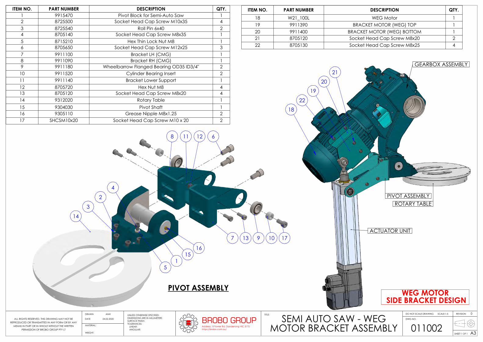
PIVOT ASSEMBLY
GEARBOX ASSEMBLY
ACTUATOR UNIT
ROTARY TABLE
WEG MOTOR SIDE BRACKET DESIGN
18
19
20
22
21
PIVOT ASSEMBLY
1
2
3
4
5
7
8 11 12
9 10 17
6
14
1516
13
ITEM NO. PART NUMBER DESCRIPTION QTY.1 9915470 Pivot Block for Semi-Auto Saw 12 8725500 Socket Head Cap Screw M10x35 43 8725540 Roll Pin 6x40 24 8705140 Socket Head Cap Screw M8x35 15 8715210 Hex Thin Lock Nut M8 16 8705650 Socket Head Cap Screw M12x25 37 9911100 Bracket LH (CMG) 18 9911090 Bracket RH (CMG) 19 9911180 Wheelbarrow Flanged Bearing OD35 ID3/4" 2
10 9911520 Cylinder Bearing Insert 211 9911140 Bracket Lower Support 112 8705720 Hex Nut M8 413 8705120 Socket Head Cap Screw M8x20 414 9312020 Rotary Table 115 9304030 Pivot Shaft 116 9305110 Grease Nipple M8x1.25 217 SHCSM10x20 Socket Head Cap Screw M10 x 20 2
ITEM NO. PART NUMBER DESCRIPTION QTY.18 W21_100L WEG Motor 119 9911390 BRACKET MOTOR (WEG) TOP 120 9911400 BRACKET MOTOR (WEG) BOTTOM 121 8705120 Socket Head Cap Screw M8x20 222 8705130 Socket Head Cap Screw M8x25 4
UNLESS OTHERWISE SPECIFIED:DIMENSIONS ARE IN MILLIMETERSSURFACE FINISH:TOLERANCES: LINEAR: ANGULAR:
MATERIAL:
DO NOT SCALE DRAWING REVISIONTITLE:
DWG NO.
SCALE:1:5
SHEET 1 OF 1 A3WEIGHT: 011002
SEMI AUTO SAW - WEG MOTOR BRACKET ASSEMBLY
BROBO GROUPAddress : 8 Fowler Rd, Dandenong VIC 3175https://brobo.com.au/
24.02.2020
0DRAWN
DATE
ANH
ALL RIGHTS RESERVED. THIS DRAWING MAY NOT BE REPRODUCED OR TRANSMITTED IN ANY FORM OR BY ANY
MEANS IN PART OR IN WHOLE WITHOUT THE WRITTEN PERMISSION OF BROBO GROUP PTY LT
1
14
2
15
3
4
6
5
7
8
9
10
18
12
13
11
17
19
3
16
16
Weight ~18 Kg
ITEM NO.
PART NUMBER DESCRIPTION QTY.
1 1031360 Handnut 1
2 9515270 External Circlip 1500-15 1
3 9305670 O Ring t=3/16" , ID=2" , OD=2 3/8" 2
4 9324730 Vice Leadscrew ⌀30x270 1
5 9312210 End Cap 1
6 9305700 O Ring t=1/8" , ID=5 3/4" , OD=6" 1
7 9302230 Piston 1
8 9305690 O Ring t=1/4" , ID=5 1/2" , OD=6" 1
9 9322190 Air Vice Cylinder Housing 1
10 9304740 Piston Rod Boyler Tube 1
11 9305680 Rod Wiper 1
12 9312200 Vice Jaw 1
13 9314100 Jaw Wear Plate 1
14 8705940 Roll Pin 4x24 1
15 8735490 Button Head Cap Screw M6x12 8
16 2l34002 4 1/8 Fox Swivel Elbow 2
17 8705290 Socket Head Cap Screw M12x75 2
18 9314280 Vice Block Clamp 2
19 8705340 Flat Socket Head Cap Screw M6x16 4
UNLESS OTHERWISE SPECIFIED:DIMENSIONS ARE IN MILLIMETERSSURFACE FINISH:TOLERANCES: LINEAR: ANGULAR:
MATERIAL:
DO NOT SCALE DRAWING REVISIONTITLE:
DWG NO.
SCALE:1:5
SHEET 1 OF 1 A3WEIGHT: 9311200PNEUMATIC VICE ASSEMBLYBROBO GROUP
Address : 8 Fowler Rd, Dandenong VIC 3175https://brobo.com.au/
26.08.2020
0DRAWN
DATE
ANH
ALL RIGHTS RESERVED. THIS DRAWING MAY NOT BE REPRODUCED OR TRANSMITTED IN ANY FORM OR BY ANY
MEANS IN PART OR IN WHOLE WITHOUT THE WRITTEN PERMISSION OF BROBO GROUP PTY LT

OPTIONAL
67
12
8
910 11
3
9501460 3M BROBORULE LENGTH STOP KIT
45
9501490
9501450 3M LENGTH STOP & CONVEYOR
67123
5 4
BOM TableITEM NO. PART NUMBER DESCRIPTION QTY.
1 9505910 Carriage Track 3.0 Metre 12 9505940 Measuring Tape 5Mx19 13 9512110 Angle Bracket 34 8705570 Button Head Cap Screw M8x40 35 8705580 Hex Head Screw M8x40 36 9501560 Mirco Flip Included Arm 17 9501210 Brobo 68 Kg Conveyor Roller 3000x305x150mm Pitch 28 9504320 Adjuststable Stand 610 - 1016 mm 29 9501240 Mounting Bracket Conveyor RH 110 9501250 Mounting Bracket Conveyor LH 111 8705170 Socket Head Cap Screw M10x25 4
ITEM NO.
PART NUMBER DESCRIPTION QTY.
1 9505910 Carriage Track 3.0 Metre 12 9505940 Measuring Tape 5Mx19 13 9512110 Angle Bracket 34 8705570 Button Head Cap Screw M8x40 35 8705580 Hex Head Screw M8x40 36 9501560 Mirco Flip Included Arm 17 9501210 Brobo 68 Kg Conveyor Roller 3000x305x150mm Pitch 1
UNLESS OTHERWISE SPECIFIED:DIMENSIONS ARE IN MILLIMETERSSURFACE FINISH:TOLERANCES: LINEAR: ANGULAR:
MATERIAL:
DO NOT SCALE DRAWING REVISIONTITLE:
DWG NO.
SCALE:1:18
SHEET 1 OF 1 A3WEIGHT: 95014603M BROBO LENGTH STOP KIT BROBO GROUP
Address : 8 Fowler Rd, Dandenong VIC 3175https://brobo.com.au/
28.10.2020
0DRAWN
DATE
ANH
ALL RIGHTS RESERVED. THIS DRAWING MAY NOT BE REPRODUCED OR TRANSMITTED IN ANY FORM OR BY ANY
MEANS IN PART OR IN WHOLE WITHOUT THE WRITTEN PERMISSION OF BROBO GROUP PTY LT

6
128
910
3
9501480 6M BROBORULE LENGTH STOP KIT
OPTIONAL
47
5
9501470 6M LENGTH STOP & CONVEYOR
67
124 3
5
ITEM NO. PART NUMBER DESCRIPTION QTY.1 9505900 Carriage Track 6.0 Metre 12 9505950 Measuring Tape 8Mx19 13 9512110 Angle Bracket 64 8705570 Button Head Cap Screw M8x40 65 8705580 Hex Head Screw M8x40 66 9501560 Mirco Flip Included Arm 17 9501210 Brobo 68 Kg Conveyor Roller 3000x305x150mm Pitch 38 9504320 Adjuststable Stand 610 - 1016 mm 39 9501240 Mounting Bracket Conveyor RH 1
10 9501250 Mounting Bracket Conveyor LH 111 8705170 Socket Head Cap Screw M10x25 4
ITEM NO. PART NUMBER DESCRIPTION QTY.1 9505900 Carriage Track 6.0 Metre 12 9505950 Measuring Tape 8Mx19 13 9512110 Angle Bracket 64 8705570 Button Head Cap Screw M8x40 65 8705580 Hex Head Screw M8x40 66 9501560 Mirco Flip Included Arm 17 9501210 Brobo 68 Kg Conveyor Roller 3000x305x150mm Pitch 2
UNLESS OTHERWISE SPECIFIED:DIMENSIONS ARE IN MILLIMETERSSURFACE FINISH:TOLERANCES: LINEAR: ANGULAR:
MATERIAL:
DO NOT SCALE DRAWING REVISIONTITLE:
DWG NO.
SCALE:1:18
SHEET 1 OF 1 A3WEIGHT: 95014806M BROBO LENGTH STOP KIT BROBO GROUP
Address : 8 Fowler Rd, Dandenong VIC 3175https://brobo.com.au/
22.04.2020
0DRAWN
DATE
ANH
ALL RIGHTS RESERVED. THIS DRAWING MAY NOT BE REPRODUCED OR TRANSMITTED IN ANY FORM OR BY ANY
MEANS IN PART OR IN WHOLE WITHOUT THE WRITTEN PERMISSION OF BROBO GROUP PTY LT

34
10
5
7
9
6
8
1617
18
2019
15
12
24
9501560 MICRO FLIP
92
8
11
14
22
21
20
12
5
23
25
A
39
28
OPTIONAL9501590
ITEM NO. PART NO. DESCRIPTION QT
Y.1 9505910 Aluminium Extrusion 3m 12 9505940 Measuring Tape 5Mx19 13 9504007 Nylon Wear Strip L90x100x15 24 9504005 Carriage 8x90x100L 25 9504000 Shaf Support ⌀16 26 12131X Adjustable Hand Levers M10x40 27 9504850 Nylon Flat Washer M16 (⌀30x ⌀17x 3) 48 8705750 Hex Nut M16 ZINC PLATED 29 9505920 Micro Stop (Thumb Nut) 1
10 8735370 Stud M16x250 111 9504008 Clamping Pad 50x50x10 212 8726100 Button Head Socket Screw M6x16 413 8705100 Socket Head Cap Screw M6x40 814 9504010 Rotation Arm 115 9504860 Nylon Bushes M16 (⌀19x ⌀16.1x17 + ⌀34.5x3) 216 9504020 Mounting Plate Shape L2 117 9505930 Stop Plate 99 x 85 x 6 118 9502100 Extension Arm Stop 119 9504840 Wear Plate 50x40x5 120 8705340 Flat Socket Head Cap Screw M6x16 521 8715080 Dowel Pin 8x25 122 8705130 Socket Head Cap Screw M8x25 123 8705070 Socket Head Cap Screw M6x20 324 9504830 45 Offset Indicator 125 8705930 Slotted Spring Pin 4x16 2
UNLESS OTHERWISE SPECIFIED:DIMENSIONS ARE IN MILLIMETERSSURFACE FINISH:TOLERANCES: LINEAR: ANGULAR:
MATERIAL:
DO NOT SCALE DRAWING REVISIONTITLE:
DWG NO.
SCALE:1:2
SHEET 1 OF 2 A3WEIGHT: 9501590
MANUAL LENGTH STOP ASSEMBLY 3M
BROBO GROUPAddress : 8 Fowler Rd, Dandenong VIC 3175https://brobo.com.au/
19.06.2020
0DRAWN
DATE
ANH
ALL RIGHTS RESERVED. THIS DRAWING MAY NOT BE REPRODUCED OR TRANSMITTED IN ANY FORM OR BY ANY
MEANS IN PART OR IN WHOLE WITHOUT THE WRITTEN PERMISSION OF BROBO GROUP PTY LT

1160 1000
1160 1000
126
2
1
3
116
0
1000
30
250
AS:4068-1993 Flat pallets for materials handling
ITEM NO. PART NUMBER DESCRIPTION QTY.1 W90x45x1000 90x45x1000 32 W100x20x1160 100x20x1160 73 W100x16x1160 100x16x1160 3
MATERIAL:
DO NOT SCALE DRAWING REVISIONTITLE:
DWG NO.
SCALE:1:10
SHEET 1 OF 1 A3WEIGHT:
8815020PALLET ASSEMBLY FOR
SEMI AUTO SAWBROBO GROUPAddress : 8 Fowler Rd, Dandenong VIC 3175https://brobo.com.au/
09.12.20190DRAWN BY
DATEANH
ALL RIGHTS RESERVED. THIS DRAWING MAY NOT BE REPRODUCED OR TRANSMITTED IN ANY FORM OR BY ANY MEANS IN PART OR IN WHOLE WITHOUT THE WRITTEN PERMISSION OF BROBO GROUP PTY LT
SIZE TO MATCH CAST* 6 mm 0.1 0.5 30 mm 0.2 0.5 100 mm 0.3 1.5 300 mm 0.5 2.01000 mm 0.6 3.02000 mm 1.2 5.0
GRADE RA (µm) N1 0.025 N2 0.05 N3 0.1 N4 0.2 N5 0.4 N6 0.8
GRADE RA (µm) N7 1.6 N8 3.2 N9 6.3 N10 12.5 N11 25.0 N12 50.0
TOLERANCES ON DIMENSIONS ARE METRICDIMENSIONS ARE IN MILLIMETERS
ANGULARITY TOLERANCE < 0 10'CONCENTRICITY 0.1 mm
REMOVE ALL BURRS & SHARP EDGES BY 0.3 x 45
UNLESS OTHERWISE STATED
-
49
39
4
8
7
5
2
1
10
11
12
15 14
1
15
13
394 7 85
17
16
18
19
20 21 22 24
6
ITEM NO. PART NUMBER DESCRIPTION QTY.
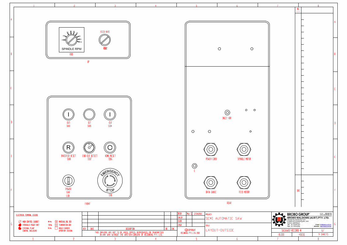
1 9911530 Metal Enclosures SA 12 9935790 Enclosure Decal 13 9935470 Stop/E-Stop Push Button 14 9935440 Cut Push Button 25 9935450 On Off Button 16 9935530 LED M22-LED230 17 9935660 Reset Push Button 18 9935460 Set Push Button 19 9911510 Potentiometer 210 9505024 AC Drives, 3HP, 230V 1PH Input/ 3PH Output 111 9935280 AC/DC DIN Rail Power Supply 240 W, 48 V, 5 A 112 9315210 240V AC Contactor 113 DRail Zinc Plated Rail 220 mm 114 9305600 Cable Gland Plastic, M20 215 9935800 Cable Gland Plastic, M12 416 EA01 Earth Assembly 117 GS01 Ground Sticker 118 9911210 Plug 119 9911200 Solenoid Valve 120 RCK12T-2TEL 12 Pin Cable & Plug 121 WAKW 4.4T-2 Cable 4 Pin 122 8745270 Bdl 5 Core 30/0.25 123 9911600 Motor Cable 1
UNLESS OTHERWISE SPECIFIED:DIMENSIONS ARE IN MILLIMETERSSURFACE FINISH:TOLERANCES: LINEAR: ANGULAR:
MATERIAL:
DO NOT SCALE DRAWING REVISIONTITLE:
DWG NO.
SCALE:1:2.5
SHEET 1 OF 1 A3WEIGHT: 9911020
SEMI AUTO SAW ENCLOSURECOMPONENTS
BROBO GROUPAddress : 8 Fowler Rd, Dandenong VIC 3175https://brobo.com.au/
20.08.2020
0DRAWN
DATE
ANH
ALL RIGHTS RESERVED. THIS DRAWING MAY NOT BE REPRODUCED OR TRANSMITTED IN ANY FORM OR BY ANY
MEANS IN PART OR IN WHOLE WITHOUT THE WRITTEN PERMISSION OF BROBO GROUP PTY LT

AIR INTAKEGAUGE 12 BAR
MOUNT TO LOWER BRACKET
TO PIVOT BLOCK
BRACKET
AIR FR UNIT
DOUBLE BANJO
REDUCER
CAM
LOWER BRACKET
ROLLER VALVE
PILOT/SPRING VALVE
SILENCER
AIR VICE 02
RETURN LINE
DOUBLE MALE ELBOW
DISTRIBUTOR
AIR VICE 01
PRESSURE REGULATOR(OPTION)
TUBING - 6mm TUBING - 4mm
TUBING - 6mm
TUBING - 6mm
UNLESS OTHERWISE SPECIFIED:DIMENSIONS ARE IN MILLIMETERSSURFACE FINISH:TOLERANCES: LINEAR: ANGULAR:
MATERIAL:
DO NOT SCALE DRAWING REVISIONTITLE:
DWG NO.
SCALE:1:4
SHEET 2 OF 2 A3WEIGHT: 12.67-
PNEUMATIC DIAGRAM DOUBLE AIR VICEBROBO GROUP
Address : 8 Fowler Rd, Dandenong VIC 3175https://brobo.com.au/
12.09.2019
0DRAWN
DATE
ANHALL RIGHTS RESERVED. THIS DRAWING MAY NOT BE
REPRODUCED OR TRANSMITTED IN ANY FORM OR BY ANY MEANS IN PART OR IN WHOLE WITHOUT THE WRITTEN
PERMISSION OF BROBO GROUP PTY LT


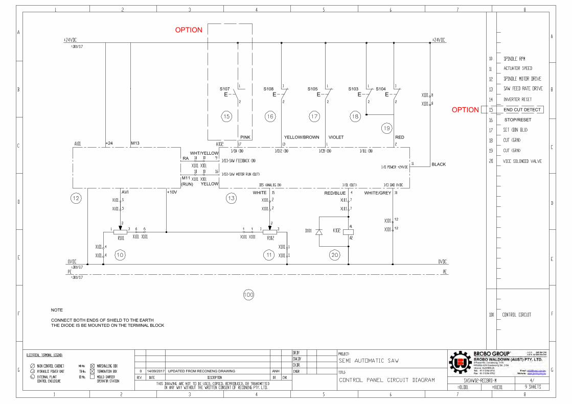
Control Cords Colour Codes for Brobo Semi Auto Saw
* Supply Power to Stepper motor* Transfer & return signals to stepper PLC
Pin MD‐CS610 Wire Turck RKC12T‐x Signal Function 1 Brown Brown IN4 General purpose programmable input 4. 2 Blue White IN2 General purpose programmable input 2.3 White Blue INPUT_REF Biases the input as sinking or sourcing
4 Green Black IN1/CAPTURE General purpose programmable input with the alternate function of being a
dedicated CAPTURE input.5 Pink Gray IN3 General purpose programmable input 3.6 Yellow Pink ANALOG_IN Analog input7 Black Violet LOGIC_GND Logic ground (non‐isolated)8 Gray Orange SIGNAL_OUTPUT_ EMITTER High speed signal output emitter 9 Red Gray/Pink SIGNAL_OUTPUT_ COLLECTOR High speed signal output collector 10 Violet White/Blue OUTPUT 1+ Output 1 + polarity 11 Gray/Pink White/Gray OUTPUT 2+ Output 2 + polarity 12 Red/Blue Gray/Brown OUTPUT 1/2 ‐ Output 1 and 2 — polarity
E2019041701 17/04/2019

E2019090601 27.04.2021
DELTA VFD‐EL PARAMETER
PARAMETERS SET VALUE FUNCTION
00.03 1 Display the actual output frequency01.00 95 Max Output Frequency %01.02 220 Maximum Output Voltage (Vmax) ‐ 3Ph01.09 3.0 Accel Time 101.10 3.0 Decel Time 102.00 1 0 To +10V From AVI02.01 1 External Terminals. Keypad STOP/RESET Disabled04.08 5 External Reset ‐ No Contact04.12 20.0 Min AVI Frequency %07.00 7.8 or 3.9 Motor Rated Current ‐ WEG ‐ Δ or Y
PARAMETERS SET VALUE FUNCTION
01.00 95 Max Output Frequency %01.02 415 or 220 or 460 Maximum Output Voltage (Vmax) 01.09 3.0 Accel Time 101.10 3.0 Decel Time 102.00 1 0 To +10V From AVI02.01 1 External Terminals. Keypad STOP/RESET Disabled04.12 20.0 Min AVI Frequency %
1. VARI SPEED SAW ‐ AUSTRALIA 1PH 240V SUPPY
2. SEMI AUTO SAW ‐ AUTSTRALIA 415V ‐ USA 220V OR 460V

Brobo Roller Conveyor290 x 3000mmØ50mm Rollers
PART NO: 9501210Roller Load Capacity - (each) (kg): 60Total Load Capacity (kg): 1200Number of Rollers (No.): 20Table Width (W) (mm): 290Table Length (L) (mm): 3000Roller Table Height (H) (mm): 80Roller Diameter (mm): Ø50
Features• Roller capacity of 60kg each• 20 x Zinc plated steel rollers at 150mm pitch• Rollers are Ø50mm with commercial bearings• Frames are powder coated• Conveyor is pre-assembled with 7 cross-members• Frames are pre-drilled at 75mm pitch to accept "Optional 19 rollers" totalling to 39 rollers
Please Note:• Roller load capacity is calculated on even weight distribution over entire roller• Total load capacity is calculated on even weight distribution over entire roller conveyor system
Includes• 20 steel rollers @ 150mm pitch


ANH14/09/20170 UPDATED FROM RECONENG DRAWING
+24 M13
RA
M11
AVI +10V
(RUN)
S107
ES108
ES105 S103 S104
E E E
BROBO GROUPAddress : 8 Fowler Rd, Dandenong VIC 3175http://brobo.com.au/
BLACK
REDVIOLETYELLOW/BROWNPINK
WHITE/GREYRED/BLUEWHITE
STOP/RESET
12
121 1
YELLOW
WHT/YELLOW
NOTE
CONNECT BOTH ENDS OF SHIELD TO THE EARTHTHE DIODE IS BE MOUNTED ON THE TERMINAL BLOCK
END CUT DETECT
ANH14/09/20170 UPDATED FROM RECONENG DRAWING
+24 M13
RA
M11
AVI +10V
(RUN)
S107
ES108
ES105 S103 S104
E E E
BROBO GROUPAddress : 8 Fowler Rd, Dandenong VIC 3175http://brobo.com.au/
BLACK
REDVIOLETYELLOW/BROWNPINK
WHITE/GREYRED/BLUEWHITE
STOP/RESET
12
12
OPTION
1 1
YELLOW
WHT/YELLOW
NOTE
CONNECT BOTH ENDS OF SHIELD TO THE EARTHTHE DIODE IS BE MOUNTED ON THE TERMINAL BLOCK
END CUT DETECTOPTION


87
174
A
A 588
SECTION A-A
BACK VIEWSCALE 1:2
3
12
ITEM NO. Number Rev QTY. Name & Material
3 208242 4 BOLT CAP/SCR, M5 20 LN, SOCKET HEAD - 2 9911460 1 ACTUATOR, 200 STROKE - ASSEMBLY - -1 9911450 1 STEP MOTOR, DOUBLE STACK -
MACHINEFINISHES
MATERIALCH.DR.CHK.BYDR.BY O.DJ.
S.R.
REV. DESCRIPTION DATE CHK.REVISIONS
THIRDANGLE
BREAK SHARP EDGESAND REMOVE ALL BURRS SHEET
SIZE REV.
A3PART/FILE NO.
AC80L
Size To Mach.6 mm ± 0.1
30 mm ± 0.2120 mm ± 0.3400 mm ± 0.5
1000 mm ± 0.82000 mm ± 1.2
UNLESS OTHERWISE SPECIFIEDDIMENSIONS ARE METRIC
GENERAL LINEAR/ANGULAR &FORM AND POSITION TOLERANCES
ACC. TO DIN ISO 2768-mK
RECONENG Industrial Engineeringwww.reconeng.com.au
WEIGHT
SCALE
1:2
TITLEDACTUATOR, MD34AC DRIVE, 200 STROKE
07.06.201629.03.2013
11/03
-ASSEMBLY
THIS
DR
AWIN
G IS
TH
E C
ON
FID
ENTI
AL P
RO
PER
TY O
F R
ECO
NEN
G-IE
PTY
LTD
AN
D S
HAL
L N
OT
BE U
SED
IN P
ART
OR
WH
OLE
WIT
HO
UT
PRIO
R W
RIT
TEN
PER
MIS
SIO
N F
RO
M R
ECO
NEN
G-IE
PTY
LTD
. TH
IS D
RAW
ING
IS N
OT
A VA
LID
ATED
DES
IGN
AN
D IT
S FI
TNES
S FO
RPU
RPO
SE IS
NO
T W
ARR
ANTE
D U
ND
ER A
NY
CIR
CU
MST
ANC
ES U
NLE
SS IT
HAS
BEE
N V
ALID
ATED
BY
BOTH
AN
ALYS
IS A
ND
TES
T. T
HIS
DR
AWIN
G IS
REC
ON
ENG
-IE P
TY L
TD IN
TELL
ECTU
AL P
RO
PER
TY W
ITH
ALL
RIG
HTS
RES
ERVE
D.
STOCK
DIMENSIONS
FABRICATIONS
-
-
Approved
S.R.07.06.2016MACHINED CONNECTION PLATE ADDED03
UNCONTROLLED IF PRINTED - CHECK CURRENT REVISION

Brobo Group brobo.com.au
CHAPTER 5 - Adjustments to the Saw Unit
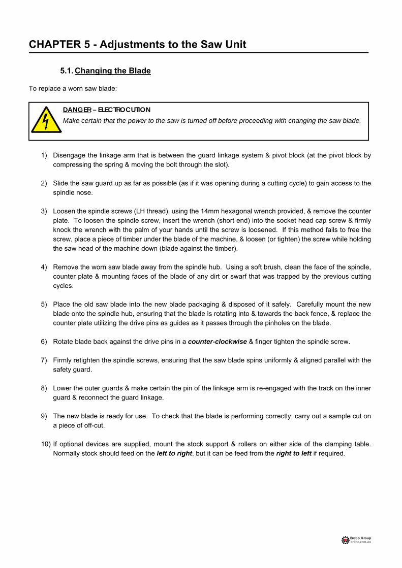
5.1. Changing the Blade To replace a worn saw blade:
1) Disengage the linkage arm that is between the guard linkage system & pivot block (at the pivot block by
compressing the spring & moving the bolt through the slot).
2) Slide the saw guard up as far as possible (as if it was opening during a cutting cycle) to gain access to the spindle nose.
3) Loosen the spindle screws (LH thread), using the 14mm hexagonal wrench provided, & remove the counter
plate. To loosen the spindle screw, insert the wrench (short end) into the socket head cap screw & firmly knock the wrench with the palm of your hands until the screw is loosened. If this method fails to free the screw, place a piece of timber under the blade of the machine, & loosen (or tighten) the screw while holding the saw head of the machine down (blade against the timber).
4) Remove the worn saw blade away from the spindle hub. Using a soft brush, clean the face of the spindle,
counter plate & mounting faces of the blade of any dirt or swarf that was trapped by the previous cutting cycles.
5) Place the old saw blade into the new blade packaging & disposed of it safely. Carefully mount the new
blade onto the spindle hub, ensuring that the blade is rotating into & towards the back fence, & replace the counter plate utilizing the drive pins as guides as it passes through the pinholes on the blade.
6) Rotate blade back against the drive pins in a counter-clockwise & finger tighten the spindle screw.
7) Firmly retighten the spindle screws, ensuring that the saw blade spins uniformly & aligned parallel with the
safety guard.
8) Lower the outer guards & make certain the pin of the linkage arm is re-engaged with the track on the inner guard & reconnect the guard linkage.
9) The new blade is ready for use. To check that the blade is performing correctly, carry out a sample cut on
a piece of off-cut.
10) If optional devices are supplied, mount the stock support & rollers on either side of the clamping table. Normally stock should feed on the left to right, but it can be feed from the right to left if required.
DANGER – ELECTROCUTION
Make certain that the power to the saw is turned off before proceeding with changing the saw blade.
Brobo Group brobo.com.au
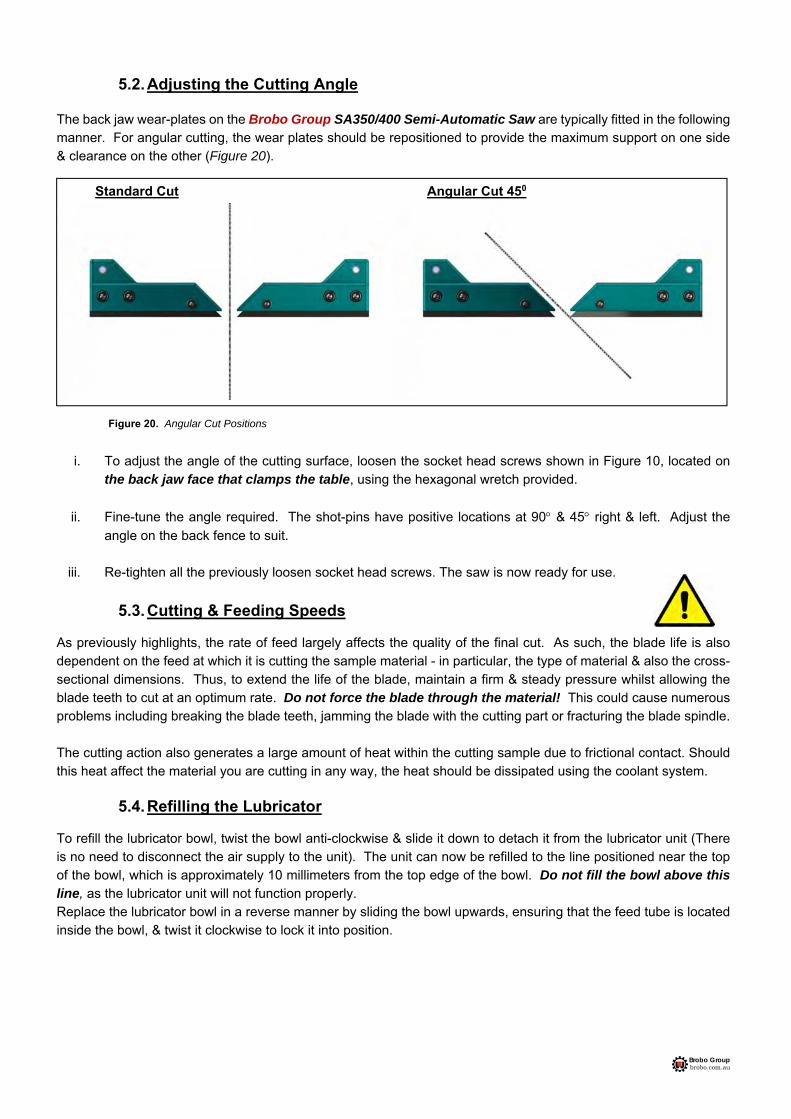
5.2. Adjusting the Cutting Angle The back jaw wear-plates on the Brobo Group SA350/400 Semi-Automatic Saw are typically fitted in the following manner. For angular cutting, the wear plates should be repositioned to provide the maximum support on one side & clearance on the other (Figure 20).
i. To adjust the angle of the cutting surface, loosen the socket head screws shown in Figure 10, located on the back jaw face that clamps the table, using the hexagonal wretch provided.
ii. Fine-tune the angle required. The shot-pins have positive locations at 90 & 45 right & left. Adjust the
angle on the back fence to suit.
iii. Re-tighten all the previously loosen socket head screws. The saw is now ready for use.
5.3. Cutting & Feeding Speeds As previously highlights, the rate of feed largely affects the quality of the final cut. As such, the blade life is also dependent on the feed at which it is cutting the sample material - in particular, the type of material & also the cross-sectional dimensions. Thus, to extend the life of the blade, maintain a firm & steady pressure whilst allowing the blade teeth to cut at an optimum rate. Do not force the blade through the material! This could cause numerous problems including breaking the blade teeth, jamming the blade with the cutting part or fracturing the blade spindle. The cutting action also generates a large amount of heat within the cutting sample due to frictional contact. Should this heat affect the material you are cutting in any way, the heat should be dissipated using the coolant system.
5.4. Refilling the Lubricator
To refill the lubricator bowl, twist the bowl anti-clockwise & slide it down to detach it from the lubricator unit (There is no need to disconnect the air supply to the unit). The unit can now be refilled to the line positioned near the top of the bowl, which is approximately 10 millimeters from the top edge of the bowl. Do not fill the bowl above this line, as the lubricator unit will not function properly. Replace the lubricator bowl in a reverse manner by sliding the bowl upwards, ensuring that the feed tube is located inside the bowl, & twist it clockwise to lock it into position.
Standard Cut Angular Cut 450
Figure 20. Angular Cut Positions
Brobo Group brobo.com.au
5.5. Adjusting the Brobolube Unit
When assembled, the Brobolube unit is a precise instrument that supplies an accurate quantity of lubricant directly to the saw blade before it contacts the workpiece. There are 2 control variables available for the operator: Air Flow (Volume) Delivery Regulated with the tap (needle valve), this can be adjusted from initial, completely closed to fully open states. It is highly recommended that the upper end of the flow range be utilized to allow adequate airflow to deposit & evenly distributed the lubricant onto the blade while maintaining a fine lubricant mix. If the needle valve is not open sufficiently, the air to lubricant ratio may vary & may result in a substandard distribution of lubricant to reach the blade teeth.
Lubricator Flow Rate This controls the fluid flow rate & is adjustable via the slotted needle valve situated on top of the lubricator. The consumption of Brobolube is factory set to 4 drops per minute. This has been examined to produce a sufficient mix of air & lubricant, & it is recommended to use this initial setting. On this setting, approximately 55 cubic centimeters (lubricator capacity) should last for 20 hours of continuous cutting. If for some reason the setting needs to be altered, the needle valve should be turned clockwise to reduce or anti-clockwise to increase the fluid flow respectively. NOTE
i. Although the lubricator is capable of delivering a much higher flow rate of lubricant, it is suggested that you do not increase the flow rate excessively because:
No significant increase in blade life or lubricating efficiency will be achieved (confirmed by test results).
Excessive application of Brobolube will only result in a waste of fluid.
The excessive application will produce swarf that will be wet (oily) & harder to clean up than dry swarf produced from the correct supply of Brobolube.
ii. The amount of Lubricant (when set correctly) delivered by the lubricator is not easily visible to the naked
eye. If in doubt that lubricant is being delivered, first check to see if lubricator itself is delivering droplets at its sight glass. If still unsure whether lubricant is being delivered, disconnect the supply tubing to the tap (needle valve) & hold the tube against some blotting paper for a few seconds while the lubricator is operating.

Brobo Group brobo.com.au
5.5.1. Lubricating Oil Precautions - Health Hazard Information
The Brobolube lubricating fluid has no known adverse health effects. "Brobolube" is non-toxic, odourless, non-flammable below approximately 350ºC, & non-corrosive, although it may affect some types of rubber. There are no traces of sulfur, chlorine, phenol or nitrates found in Brobolube. When comes into contact with skin, the oil may be removed by wiping away the excess, then washing the contaminated area with detergent & water. If the oil is utilized at high temperatures, appropriate protective apparel should be worn as the oil could cause burns to skin or eyes. If splashed by hot oil, immediately run cold water over the burn area & apply first aid burn treatment. If the Brobolube delivery line breaks or becomes disconnected during operation, ensure that the air supply to the system is disconnected before repairing the problem. It is recommended that footwear with anti-slip soles be worn at all times. Any spills will result in potentially hazardous slippery surfaces & should be dealt with promptly to prevent physical injury resulting from falls. Do not use coarsely, combustible material like sawdust to soak up oil due to the potential risk of spontaneous combustion. Spilled oil should be transferred into non-porous containers of suitable strength. Any remaining oil should be cleaned up with sand or other non-combustible, absorbent material. Place the sand & oil mixture into containers & disposed of by an EPA approved landfill or alternatively, by a suitable non-polluting method. In addition, rags soaked in oil should not be burned. Do not pour oil down the drain, which would ultimately contaminate the water supply & pollute the environment. For firefighting purposes, either use CO2, dry chemical or foam retardant to extinguish the flames.
Brobo Group brobo.com.au
CHAPTER 6 – Maintenance & Selection of Consumables
6.1. Role of the Operator The person operating & maintaining the Brobo Group SA350/400 Semi-Automatic Saw must familiarise themselves with these instructions for their own safety & that of the others, in addition to safeguarding the production of the machine. Responsibility must be taken by the user on the general maintenance & up keeping of the unit as specified in this chapter, with particular emphasis on:
Check to ensure that other operators of the machine always aware of and comply with the relevant safety instructions & standards as specified in Chapter 2 - Safety & Accident Prevention. Therefore, check that the safety devices are operational & work perfectly and that personal safety requirements are complied with.
Ensure that the working cycle is efficient & guarantees maximum productivity, inspect the: o Functions of the main components of the machine o The sharpness of the blade & coolant flow o Correct working parameters for the type of material being cut
Verify that the quality of the cut meets the requirements & the final product is free from any machining defects.
6.2. Maintenance Requirements
All maintenance must be carried out with the power switched off & the machine in emergency stop condition.
To guarantee optimum operation, all spare parts must be Brobo Group originals.
On completion of maintenance works, ensure that the replaced parts or any tools used have been removed from the machines before starting it up.
Any behavior not in accordance with the instructions for using the machine specified in this manual may create hazards and/or safety risks for the operator.
Therefore, read & follow all the instructions for use & maintenance of the machine, and those on the product itself.
6.3. General Maintenance of Functioning Components The general maintenance operations that should be carried out regularly are as follows:
1) Keep the vice clamps, overall machine & path of the cutting blade free of any offcuts, accumulated swarf & coolant using compressed air or preferably thread-free cloth.
2) Observe the oil level on the gearbox. The first oil change should be performed after the initial 60 hours of
operation & 500 hours of operation thereafter. Use Brobo Gearbox Oil (Part No. 9501090) Refilling point is situated in the handle bar mounting threaded hole. The required quantity to refill is 800 ml for the S315/S350/400 gearboxes.

Brobo Group brobo.com.au
3) Change coolant as required, or whenever the coolant starts to get dirty or emits a stale odour. The coolant compensation tank should be checked regularly. Coolant level would expect to naturally decrease over time due to natural evaporation. Use premium quality coolants such as CoolTech 500 or SlideTech 68. Coolant is available from BROBO GROUP Pty. Ltd. in 2 litre & 20 litre packs (Part No. 9301570 & 9501080): Concentrate, Ratio 1:20
4) Lubricate the saw head pivot shaft & rotary table regularly (after every 40 hours of operation, or weekly) with
an NLGI 2 extreme pressure grease, Shell Alvania No.1 grease or equivalent.
5) Clean the vice & lubricate any moving joints or sliding surfaces with good quality oil.
6) Clean the machine regularly & keep any unpainted surfaces lightly oiled to protect from rust & corrosion.
7) The air supply for the pneumatic air vices should be checked regularly such that it is free of any condensed water molecules & the filter should be drained frequently.
8) Ensure that the machine performs cuts perpendicular to the work surface.
If not, contact Brobo Group engineering department.
9) Test that the blade is at right angles to the workpiece back fence. If not, contact Brobo Group engineering department.
10) Check that the 0 notch on the fixed worktable is aligned with the graduation on the turntable. If not, adjust
as described in Section 5.2.
11) Examined that the precision of the 15, 30, 45 left & right stops are correct & accurate. If they are not
adjusted properly, proceed as described in Section 5.2.
12) Regularly empty out the swarf catcher, resting directly above the compensation tank, of any offcuts & swarf that has collected during the numerous cutting cycles.

Brobo Group brobo.com.au
CHAPTER 7 - Troubleshoot
7.1. Troubleshooting For Blade & Cutting Problems
PROBLEM IDENTIFIED DIAGNOSIS SOLUTIONS
Cuts produced are not at 90 and/or are not perpendicular
Frequent and/or excessive teeth breaking
Head speed too low or too high Blade with worn teeth The angularity of blade to workpiece back fence and vice clamps Blade not perpendicular to the work surface Broken teeth Incorrect lubricant/coolant fluid Material too hard Blade not worn incorrectly
Reduce or increase head speed respectively. Replace with a new blade, with reference to Section 5.1 Changing the Blade. Adjust the position of the blade so that it is at right angles to the
workpiece back fence using the 0 notch as a reference; set the stops at
45 left & right using the method
described in Section 5.2 Adjusting the Cutting Angle. Adjust the blade using the appropriate screws such that it is perpendicular to the work surface. Check the hardness of the material being cut corresponds to the capabilities of the blade. Check the water & oil mixture; check that the holes and/or hose are not blocked; direct the nozzles correctly; check that the lubricant/coolant fluid conforms to those specified in Section 6.3 General Maintenance of Function Components. Check the cutting speed, feed speed, blade type & parameters are correct for the particular application. With a new blade, it is necessary to start cutting at half feeding speed. After a normalizing period (cutting surface about 300cm2 for hard materials & 1000cm2 for softer materials), both cutting & feed speeds can be brought up to normal values.
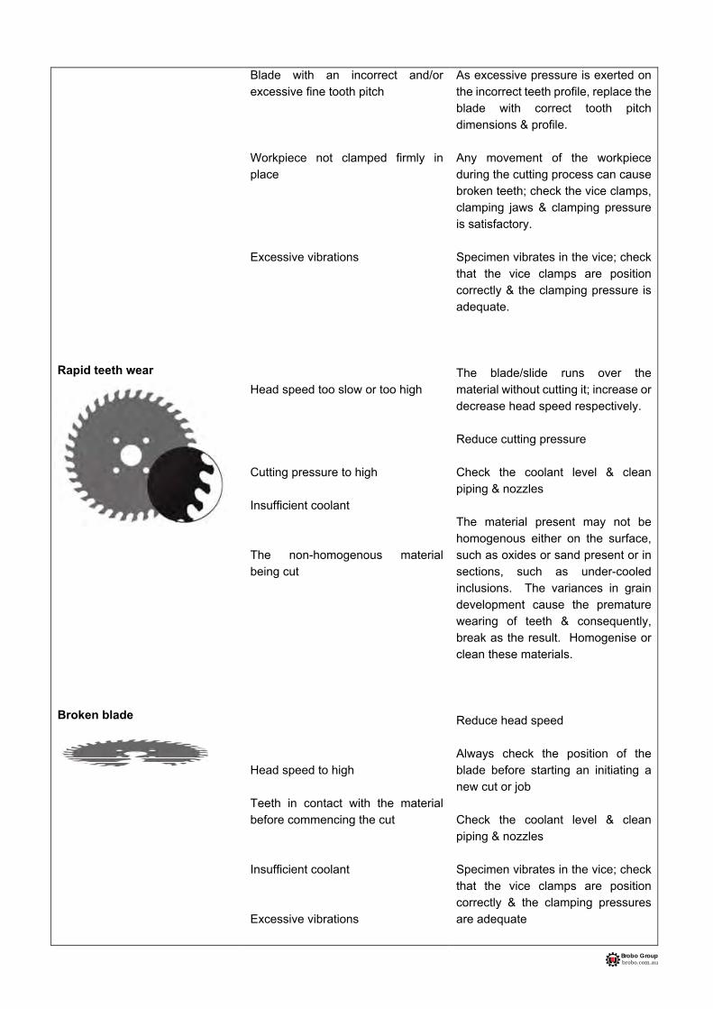
Brobo Group brobo.com.au
Rapid teeth wear Broken blade
Blade with an incorrect and/or excessive fine tooth pitch Workpiece not clamped firmly in place Excessive vibrations
Head speed too slow or too high Cutting pressure to high Insufficient coolant The non-homogenous material being cut Head speed to high Teeth in contact with the material before commencing the cut Insufficient coolant Excessive vibrations
As excessive pressure is exerted on the incorrect teeth profile, replace the blade with correct tooth pitch dimensions & profile. Any movement of the workpiece during the cutting process can cause broken teeth; check the vice clamps, clamping jaws & clamping pressure is satisfactory. Specimen vibrates in the vice; check that the vice clamps are position correctly & the clamping pressure is adequate. The blade/slide runs over the material without cutting it; increase or decrease head speed respectively. Reduce cutting pressure Check the coolant level & clean piping & nozzles The material present may not be homogenous either on the surface, such as oxides or sand present or in sections, such as under-cooled inclusions. The variances in grain development cause the premature wearing of teeth & consequently, break as the result. Homogenise or clean these materials. Reduce head speed Always check the position of the blade before starting an initiating a new cut or job Check the coolant level & clean piping & nozzles Specimen vibrates in the vice; check that the vice clamps are position correctly & the clamping pressures are adequate

Brobo Group brobo.com.au
7.2. General Troubleshooting Below lists of some of the most commonly identified problems associated with the Brobo Group SA350/400 Semi-Automatic Saw and the recommended troubleshooting procedures to undertake to rectify the situations. If the solutions provided do not resolve the problem, or the problem identified differs from those listed, immediately contact Brobo Group engineering department.
PROBLEM IDENTIFIED DIAGNOSIS SOLUTIONS
Spindle motor will not rotate Machine open slowly or not at all Coolant system not operational
Electrical power supply not connected Loose contactors Motor burnt out Blown fuses Inverter Wiring Hydraulic oil level and pressure system
Ensure that the main power cable is plugged in & switched on. Check the phases, cables, plugs & sockets for loose connection. Also, check that the motor connections are in place. Verify that the contactors are not loose. If contacts are short-circuited, contact Brobo Group engineering department immediately Check that it has not burnt out, that it turns freely & there is no moisture in the main electrical unit. The winding can be rewound or replaced Examine that the fuses are intact & fitted correctly, otherwise replace or tighten the fuse holders Inverter display shows RD0 when ready. Check the integrity of connection B2 to B4. Check for any leaks present within the catchment unit. Top up the with coolant as recommended in Section 6.3 General Maintenance of Functioning Components Check that it is not kinked, severed or blocked. Flush out any blockages

Brobo Group brobo.com.au
PROBLEM IDENTIFIED DIAGNOSIS SOLUTIONS Vice clamps do not engage
Air supply hose is not connected
Inspect that the air supply cable is connected to the air fittings located at the back of the saw
Emergency condition tripped
Check that the emergency stop button is released, specified in Section 3.1.4 Control Panels. Check the contacts & the cable connections
Air treatment unit obstructed
Check that the pneumatic input & inlet connections are not obstructed & that the supply hose is not blocked or kinked
Blocked pneumatic tubing
Check that it is not kinked, severed or blocked. Remove any blockages
Solenoid issue
Check that the solenoid is working. The solenoid will display a red light if it is on. Check the wiring of the solenoid. If there are no issues with wiring connections replace the solenoid.
Saw stops actuation while cutting, not proceeding any further into the cut.
There is a physical obstruction to the head coming down
Check if the adjustment screw is too high. Check if the actuator is not jammed. Check if there is a jam on swarf at the pivot point.
The cutting head will not ascend or descend
Power supply not switched on
Ensure that the main power cable is plugged in & switched on. Check the phases, cables, plugs & sockets for loose connection. Also, check that the motor connections are in place
Emergency condition tripped
Check that the emergency stop button is released, specified in Section 3.1.4 Control Panels. Check the contacts & the cable connections
Loose connectors
Check that the orange power connector at the actuator is not loose.
Faulty feed jog switches
Contact Brobo Group engineering department for replacement of part
Actuator jammed
Remove motor which requires four screws to be removed from the motor & actuator. Remove the motor. Using a flat head screwdriver, insert the screwdriver into the keyway & rotate. Rotate clockwise when head will not ascend. Rotate anticlockwise when head will no descend.
The blade will not reach a maximum cutting depth
Depth adjustment screw not fully released. Release the screw & recalibrate the saw. Saw must be recalibrated every time the screw is adjusted.
Tighten the depth adjustment screw fully
Workpiece deformed by a clamp
Clamp pressure too high
Lower the air pressure going to the clamps.