Embed Size (px)
Citation preview

Produced by Cloud Models,Deopham Road,Morley,Wymondham, Norfolk,NR18 9AAE-mail [email protected] web site cloudmodels.com
IntroducingThe Cloud Models
Westland Whirlwind
Thank you for purchasing the Cloud Models Westland Whirlwind we hope you are goingto enjoy building and flying it.
The Westland Whirlwind has been designed to be sport scale so as to make it straightfor-ward to build and fun to fly.
The Westland Whirlwind requires two 400 motors nicad and three-channel radio usingthree servos and a speed controller, plus glues covering paint etc.
By Tricks
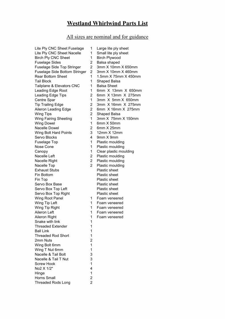
Lite Ply CNC Sheet Fuselage 1 Large lite ply sheetLite Ply CNC Sheet Nacelle 1 Small lite ply sheetBirch Ply CNC Sheet 1 Birch PlywoodFuselage Sides 2 Balsa shapedFuselage Side Top Stringer 2 3mm X 10mm X 650mmFuselage Side Bottom Stringer 2 3mm X 10mm X 460mmRear Bottom Sheet 1 1.5mm X 75mm X 450mmTail Block 1 Shaped BalsaTailplane & Elevators CNC 1 Balsa SheetLeading Edge Root 1 6mm X 13mm X 650mmLeading Edge Tips 2 6mm X 13mm X 275mmCentre Spar 1 3mm X 5mm X 650mmTip Trailing Edge 2 3mm X 16mm X 275mmAileron Leading Edge 2 6mm X 16mm X 275mmWing Tips 2 Shaped BalsaWing Fairing Sheeting 1 3mm X 75mm X 150mmWing Dowel 1 6mm X 50mmNacelle Dowel 2 6mm X 25mmWing Bolt Hard Points 3 12mm X 12mmServo Blocks 4 9mm X 9mmFuselage Top 1 Plastic mouldingNose Cone 1 Plastic mouldingCanopy 1 Clear plastic mouldingNacelle Left 2 Plastic mouldingNacelle Right 2 Plastic mouldingNacelle Top 2 Plastic mouldingExhaust Stubs Plastic sheetFin Bottom Plastic sheetFin Top Plastic sheetServo Box Base Plastic sheetServo Box Top Left Plastic sheetServo Box Top Right Plastic sheetWing Root Panel 1 Foam veneeredWing Tip Left 1 Foam veneeredWing Tip Right 1 Foam veneeredAileron Left 1 Foam veneeredAileron Right 1 Foam veneeredSnake with link 1Threaded Extender 1Ball Link 1Threaded Rod Short 12mm Nuts 2Wing Bolt 6mm 1Wing T Nut 6mm 1Nacelle & Tail Bolt 3Nacelle & Tail T Nut 3Screw Hook 1No2 X 1/2" 4Hinge 1Horns Small 2Threaded Rods Long 2
Westland Whirlwind Parts List
All sizes are nominal and for guidance

Bat
tery
box
side
Bat
tery
box
side
Dou
bler
Fuse
lage
spac
ers
Fuse
lage
spac
er
Dou
bler
Fin
top
side
Serv
o pl
ate
Bat
tery
box
rear
Snak
e su
ppor
tsFi
n re
ar p
ost
Fuse
lage
spac
er
Snak
e su
ppor
ts
Win
g bo
ltpl
ate
Tail
bolt
doub
ler
Snak
e su
ppor
t
Form
er 2
Fin
top
side
Fin
top
/tailp
lane
pla
tform
Tail
blen
der
Fin
top
side
Rea
r for
mer
Fron
tfo
rmer
Fin
fron
t pos
t
Larg
e Li
te P
ly S
heet

Small Lite Ply Sheet
Birch Plywood
Nacelle crutch bottom
Nacelle crutch bottom
Servoboxlid
Servoboxlid
Naccelle rear former
Naccelle rear former
Nacelleboltplate
Nose conehook plateNacelle former
Nacelle former
Aileron horn hard point
Tailplane boltplate
Nacelle nosering
Elevatorjoiner
Front formerdoubler
Tailplanespars
Wing bolt plate

Before You Start
Before you start read the instructions and familiarise yourself with the parts. The Whirl-wind is not intended as a beginner’s model but anyone with low wing experience should findno problem flying it. It will be noticed that there is washout built into the wing tips to helpprevent tip stalling, we suggest this is not changed. You may wish to add a hand hold forlaunching either a small inset in the wing with a grip for your fingers or an external hold couldeasily be added, a short catapult could also be used with a hook under the wing. If you wish toincorporate any of these items plan now how and when to make modifications.
The prototypes used Graupner speed 400 6volt motors with 7 cell 2000 nicad the propellersare Robbe 6 X 3 ½” Folders and a 20amp speed controller was used.
The Whirlwind can be built fairly quickly using cyno, epoxy glues and liquid polystyrene,which is good for plastic/plastic and plastic/wood joints. Do Not Use cyno, cellulose orpetroleum based glues on foam parts.
Building The Tailplane
The Tailplane construction is fairly straight forward the 2 X 1.5mm ply braces are glued intothe slots in the tailplane then sand the assembly flush rounding the leading edge and tips. Theelevator joiner is constructed using 4 pieces of 1.5mm plywood as shown in the sketches witha pushrod cut to length and sandwiched between the 2 centre laminates the ball sitting in thecentre of the tailplane cut out glue the pushrod firmly in place. The elevators are then glued tothe joiner in the normal way. When dry match the tip profile to the tailplane round the trailingedge and angle the leading edge to allow movement. The tail blender parts are glued togetherthis fits between the elevators but is glued to the fin prior to painting.
Ser
vo le
adch
anel
Cou
nter
sink
bol
t hea
din
to d
owel
har
dpoi
nt
170m
m
20m
m35
mm
Ser
vo b
oxS
ervo
lead
cha
nel
6mm
bal
sa le
adin
g ed
geN
acel
le lo
catio
ndo
wel
Mot
or le
adch
anel
Win
g lo
catio
ndo
wel
Hol
es fo
rw
ires
Bol
t har
dpoi
nts
Cen
tre li
ne o
f win
g C
entre
line
of n
acel
le
Sec
tion
thro
ugh
win
g at
nac
elle
Sec
tion
thro
ugh
win
g be
twee
nfu
sela
ge a
nd n
acel
le
Sec
tion
thro
ugh
win
g at
ser
vo b
ox
Bal
sa in
fill
Bal
sa le
adin
ged
ge Cha
nel f
orm
otor
wire
s
Blo
ck w
ing
tip
Dih
edra
l 35m
mun
der e
ach
tip
Wes
tland
Whi
rlwin
d

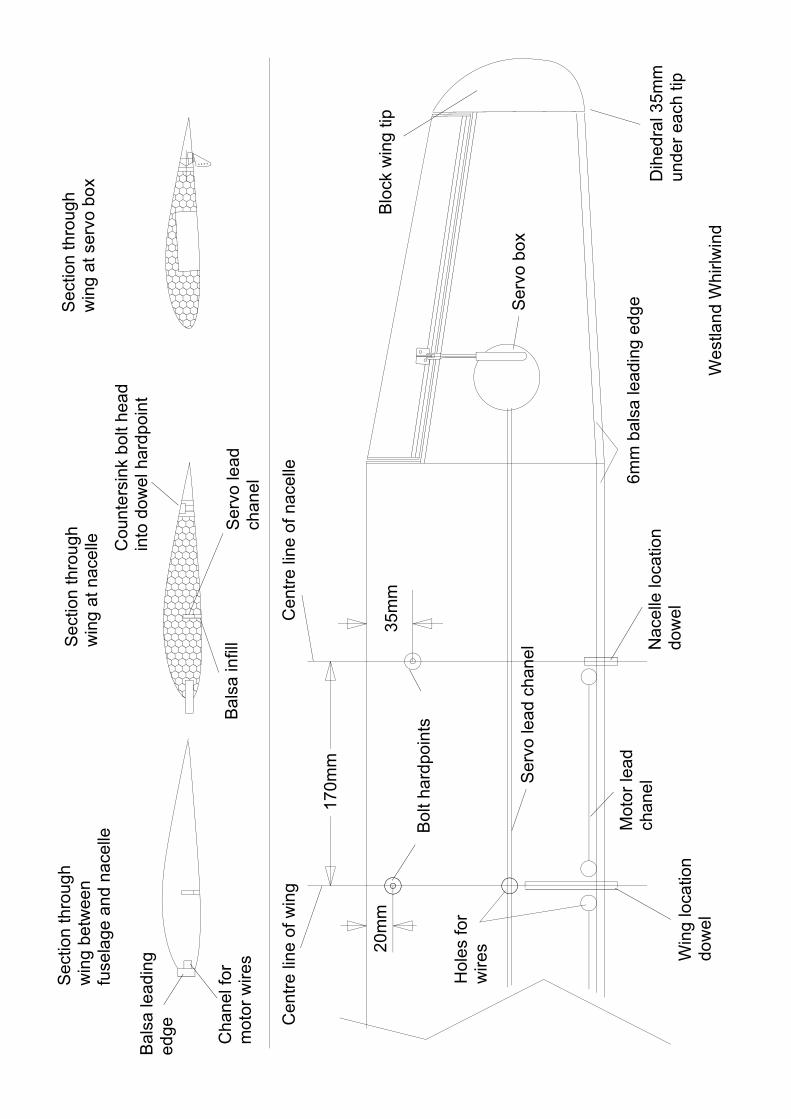
Building The Wing
Refer to sketch sheet during construction. When sanding do not cut into thesurface of the veneer just lightly finish.
Accurately mark the centre line of the wing then using the sketch mark the positions of thenacelles, their bolt holes and the fuselage bolt hole. It is important these are correct, as theflying performance of the model will suffer if not. Drill 12mm holes for the hard points (12mmDowel) and glue in place. When dry drill out the centres of the hard points to accept the wingand nacelle bolts (The nacelles look neater if the hard points are counter bored for the bolt headto sit level with the surface of the wing).
Cut a channel out of the foam at the leading edge of the wing large enough to accept yourmotor wires leave as much of the front of the wing as possible to give a good glue area for thebalsa leading edge also leave foam around the wing and nacelle dowels. The wires shouldcome out the top of the wing at the centre and the bottom of the wing at the nacelle. Put thewires in and glue on the 6mm leading edge.
From the tips remove the core from the servo well and sand smooth the bottom of the recess.Mark the position of the servo wire channel from the root wing panel and either extend the slotthrough the tip panel to the servo well or use a drill or sharpened tube to channel to the servowell. Roughly cut out the plastic servo tub moulding roughen the outside faces and epoxy inplace in the wing when dry trim level with the surface of the wing. Epoxy into the lid of theservo tub the lite ply ring when dry trim the lid level with the face of the lite ply. The servomay be mounted by servo tape directly into the wing or onto the lid using servo tape or blocks.The lid can be secured either by tack gluing in place or by putting blocks into the tub andscrewing in place.
Glue in place the 6mm leading edge 3mm trailing edge and tip block. When dry sand theassembly roughly to shape allowing for the ailerons. Lay on a flat board and pack the tips (Atthe end of the foam) to give 35mm dihedral at each tip and 17mm sweep back at the leadingedge. When satisfied epoxy the tips in place when dry run a bead of epoxy around the jointblending it out to give a strong joint. Lay the servo wires into the slot and glue in place thebalsa infill. Also face the bare end of the foam at the aileron with scrap 1.5mm balsa.
Glue in place the 6mm aileron leading edge trim the length of the aileron to fit and add 1.5mmbalsa end facings also mark the position of the aileron horns and recess and fit horn hardpoints. Angle leading edge for movement.
Lightly sand the whole assembly to finish.
After fitting to the fuselage add small pieces of sheet to the leading edge and add sheeting tothe trailing edge to allow final blending of the fuselage to the wing.

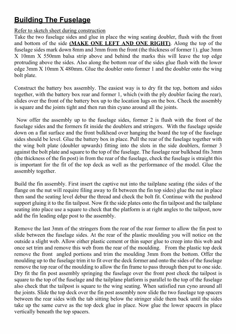
Building The FuselageRefer to sketch sheet during constructionTake the two fuselage sides and glue in place the wing seating doubler, flush with the frontand bottom of the side (MAKE ONE LEFT AND ONE RIGHT). Along the top of thefuselage sides mark down 8mm and 3mm from the front (the thickness of former 1). glue 3mmX 10mm X 550mm balsa strip above and behind the marks this will leave the top edgeprotruding above the sides. Also along the bottom rear of the sides glue flush with the loweredge 3mm X 10mm X 480mm. Glue the doubler onto former 1 and the doubler onto the wingbolt plate.
Construct the battery box assembly. The easiest way is to dry fit the top, bottom and sidestogether, with the battery box rear and former 1, which (with the ply doubler facing the rear),slides over the front of the battery box up to the location lugs on the box. Check the assemblyis square and the joints tight and then run thin cyano around all the joints.
Now offer the assembly up to the fuselage sides, former 2 is flush with the front of thefuselage sides and the formers fit inside the doublers and stringers. With the fuselage upsidedown on a flat surface and the front bulkhead over hanging the board the top of the fuselagesides should be level. Glue the battery box in place. Pull the rear of the fuselage together withthe wing bolt plate (doubler upwards) fitting into the slots in the side doublers, former 3against the bolt plate and square to the top of the fuselage. The fuselage rear bulkhead fits 3mm(the thickness of the fin post) in from the rear of the fuselage, check the fuselage is straight thisis important for the fit of the top deck as well as the performance of the model. Glue theassembly together.
Build the fin assembly. First insert the captive nut into the tailplane seating (the sides of theflange on the nut will require filing away to fit between the fin top sides) glue the nut in placethen sand the seating level debur the thread and check the bolt fit. Continue with the pushrodsupport gluing it to the fin tailpost. Now fit the side plates onto the fin tailpost and the tailplaneseating into place use a square to check that the platform is at right angles to the tailpost, nowadd the fin leading edge post to the assembly.
Remove the last 3mm of the stringers from the rear of the rear former to allow the fin post toslide between the fuselage sides. At the rear of the plastic moulding you will notice on theoutside a slight web. Allow either plastic cement or thin super glue to creep into this web andonce set trim and remove this web from the rear of the moulding. From the plastic top deckremove the front angled portions and trim the moulding 3mm from the bottom. Offer themoulding up to the fuselage trim it to fit over the deck former and onto the sides of the fuselageremove the top rear of the moulding to allow the fin frame to pass through then put to one side.Dry fit the fin post assembly springing the fuselage over the front post check the tailpost issquare to the top of the fuselage and the tailplane platform is parallel to the top of the fuselagealso check that the tailpost is square to the wing seating. When satisfied run cyno around allthe joints. Slide the top deck over the fin post assembly now slide the two fuselage top spacersbetween the rear sides with the tab sitting below the stringer slide them back until the sidestake up the same curve as the top deck glue in place. Now glue the lower spacers in placevertically beneath the top spacers.

Decide on the location of your elevator servo and RX cut the servo plate to suit and glue inplace, slide the elevator snake outer through the fin assembly and between the fuselagespacer’s mark and drill snake supports and glue in place.
Use modelling pins pushed in along the outside edge of the fuselage sides to help position thetop deck and masking tape to pull the deck down onto the sides. DO NOT GLUE DECK ATTHIS STAGETo help with the fin and nacelles it is useful to glue a sheet of sandpaper to a piece of flat wood.Rough trim the lower fin parts cutting in half along the centre line to make a left and right. Thefin halves are butt jointed. Trim the top to leave a flange (approximately 3mm) back to the rearfin post, remove the flange from here back. Trim the flange off the leading and trailing edge,then use the sanding board to adjust the moulding to fit over the fin assembly. The trailing edgeends up about 2mm thick and the leading edge a nice curve. Adjust the height by trimming thebottom of the moulding to fit over the fuselage/fin rebate. Use masking tape to assist holdingin place whilst fitting. When satisfied use masking tape to hold the fin leading edge togetherremove from the fuselage and run liquid polystyrene down the inside of the joint this willcapillary into the joint when dry remove the tape and run liquid poly down the leading edge.With the top deck taped in position spring the fin mouldings over the fin frame tape the trailingedge together and use a few strips of tape to hold the fin to the fuselage top make any finaladjustments if necessary then run liquid poly around the joints inside the fin and around theoutside of the fin deck joint when dry remove the tape and run a little more glue into the joints.Lift the deck fin assembly enough to run a bead of thick cyno or epoxy along all the joints. i.e.top of the fuselage sides top front former and top of fin frame, then pull the moulding assemblyback into position using masking tape check the step in the fin aligns with mark on fin framefor tailplane position. Sand the bottom of the fuselage smooth and sheet with 1.5mm crossgrain balsa add the blender block to the rear fuselage.Offer up the tailplane and adjust the seating so the tail fits snugly and square to the wing trimthe fin to allow elevator movement glue two pieces of scrap plastic inside the rear (ruddersection) as tabs to locate the top section of fin.
The top section of the fin is made in a similar way to the base section rough trim the mouldingto give a butt joint leaving a return at the bottom of the fin for the bolt plate to glue above becareful to align the bolt plate so the top and bottom fin sections line up. Check the fin is thesame width as the lower section particularly at the trailing edge where it sits over the tabs onthe lower fin. The tail is removable so a hole is cut in the top to allow a screwdriver in toremove the tail.
The two pieces labelled tail blender fit around the fin at the trailing edge between the elevatorsto blend in and end at a point at the tail.
If you have not yet built the wing do so now then continue.Lay the wing in place on the fuselage and drill a 6mm hole through the front bulkhead and intothe wing for the wing location dowel. Then drill through the wing bolt-hard point into the wingbolt plate and fit the 6mm captive nut in place.

Nose Cone Assembly
Glue the two round hook plate discs together then screw in the hook and glue the assemblyinto the nose cone. Sand flush the rear face of the nose cone moulding offer up the smaller nosecone former and lightly sand to fit inside remove as little as possible for a tight fit then glue
Plastic NoseMoulding
Hook
Laminated HookPlates
Laminated Formers
Dry fit the nose cone to the former and carefully sand the outer former to the nose conecontour try not to sand the moulding. Remove the moulding and line up the former with thefront of the fuselage. Drill through the two holes into the front former to accept the plastictube. Trim of two pieces of plastic tube to 10mm and glue them into the holes in the nosecone former assembly. Glue the nose cone to the former. To locate the nose loop onto thehook in the nose then fit a hook into the front bulkhead. Mark around the nose cone thenremove it and blend the fuselage bottom to the nose. Glue scrap balsa onto the wing centreto blend the wing into the fuselage.

Construct the nacelle crutch from the light ply parts keep the formers square to the base the 2 formers areparallel to each other use a nacelle side moulding to get the correct angle for the bolt location plate and doubler..
Take a pair of bottom nacelle mouldings and trim their top faces back to about 5mm as shown (keep thescrap), also remove the areas shown to assist cooling. Clean up the two inner faces to achieve a neat but joint,use the front ply ring and lite ply crutch as a guide to width and to keep the front circular. When satisfied markthe position of the crutch base. Cut a number of strips of scrap plastic 5mm wide, glue these strips along thejoining inside face of one side of the nacelle so as to form a tab either end of where the crutch sits, also gluein position the front ply ring and crutch. When dry glue in place the other nacelle side; hold in place withmasking tape until dry.
Drill the front of the nacelle to accept your motor location screws and cut away any of the flange along thetop of the nacelle to allow clearance. Make sure you cut away any areas required for ventilation of themotor.
Note it is important that the thrust line of the motor is correct, the motor shaft should be parallel to thecentre line of the nacelle and to the top face of the nacelle side mouldings. If necessary pack the motor topor bottom using a shim of ply or plastic before screwing the motor in. The motor can be removed forfinishing. To refit the motor with the leads connected, slide a piece of tube through the hole in the front ofthe nacelle and over the motor shaft, slide the motor into position and screw in place.
After Building The Wing Offer up the nacelle to the wing and drill through the nacelle hard pointand through the nacelle bolt plate, locate the captive nut. Bolt the nacelle in position, drill throughthe former for the locating dowel, glue the dowel into the wing leaving about 10mm protrudingfrom the leading edge. Offer up the top portion of the nacelle and trim the rear part away to fitover the top of the wing. It is best to remove a little at a time to achieve a neat fit, clean up thelower face to achieve a good fit to the rest of the nacelle, when satisfied glue to the bottom partof the nacelle. When dry fill any imperfections and sand with fine wet and dry.
Building The Nacelles

Finishing
Trim the canopy to fit over the cockpit area use sharp scissors warm the canopy gently if thetemperature is low so it is less brittle.
As this is not a first time model you will probably have your own preferances when it comesto finishing. The original model was finished with tissue and dope be careful to seal anyexposed foam areas the plastic parts need not be covered just lightly finished with fine wet anddry. The model was then spray finished with enamel. Lettering and markings was applied withstencils though decals would be good. Panel lines where added using a soft pencil.
Securely fit all the control surface hingesAnd fit the aileron horns.
Fit your motors and wire up. ThePrototype used the layout left alwaysDisconnect the battery when not in use.Make sure your speed controller isOf a suitable rating for the motorsAnd that the motors are adequately vented.
Finally fit your radio the control movements are: -
Aileron 9mm up and 9mm Down Measured at ROOT of Aileron
Elevator 8mm up and 8mm Down
Check your centre of gravity the model should balance 55mm from the leading edge of thewing. If necessary ballast the model to suit. The prototype weighed in at 51 ozs.
Flying
Check control movements are correct and their sense is correct. Check the centre of gravity.Make sure your motors are run and checked for direction and the battery is charged. If possiblechoose a day with a light breeze for the test flight. It is preferable to have an assistant for thefirst flight. Switch on the radio start the motors launch the model slightly nose down into windand allow it to climb out gently. Keep the speed up this is not a model to be hung on itspropellers treat it with respect until you have some height and can explore its capabilities.When you have some height try a few turns throttle back and explore the glide and the stall.On early flights keep to a reasonable speed and make your approach to landing straight in untilyou are confident. We have found the Whirlwind to be a steady flyer with no vices it is quietaerobatic and very pleasing to the eye, we hope you have as much enjoyment out of theWhirlwind as we have.
Motors
Speed Controler
Battery
Plug