Embed Size (px)
Citation preview

www.synthesprodisc.com
Prodisc-C. Modular intervertebraldisc prosthesis for restoring discheight and segmental motion in thecervical spine.
Technique Guide
(including themilling system)


Synthes 1
WarningThis description alone does not provide sufficient back-ground for direct use of the instrument set. Instruction by a surgeon experienced in handling these instruments ismandatory.Please contact your local sales representative for a training by Synthes.
Table of Contents
Image intensifier control
Introduction
Product Information
Surgical Technique
Bibliography
Prodisc-C 2
Kinematics 3
Indications and Contraindications 4
Implants 5
Instruments 8
Minimally Invasive Access, Simple and Safe 14
Surgical Technique 15
Multi-Level Cases 29
Case Examples 30
32

2 Synthes Prodisc-C Technique Guide
Prodisc-C. Modular intervertebraldisc prosthesis for restoring discheight and segmental motion in thecervical spine.
Prodisc-C is intended to replace a dis-eased and/or degenerated interverte-bral disc of the cervical spine in pa-tients with symptomatic cervical disc
Ball and socket principle– Permits a physiological range of
motion in regard to flexion/extension,rotation, and lateral bending
– Restores anatomical balance– Guided, controlled motion limits the
load on facet joints
Proven concept from the field of joint endoprosthetics
Tested materials– Superior and inferior implant plate
made of cobalt-chromium-molyb-denum alloy
– Rough surface coating of pure titanium supports bony ongrowthwithin a few months
– Inlay made of ultra-high molecularweight polyethylene (UHMWPE)
Modular anatomical design– Optimal primary stability due to keel
anchorage of the prosthesis in thevertebral body
– Anatomical footprint design for maximum end plate coverage
disease (SCDD). The Prodisc-C proce-dure is intended to significantly reducepain by allowing for the removal of thediseased disc while restoring disc
height and providing the potential formotion at the affected vertebral seg-ment.

.
17°
12°360°
11° min. 17.2°
min. 17.2°
Synthes 3
Kinematics
The kinematics correspond to the joint guidance in vertebraljoints1:
The center of rotation is located just below the superiorend plate of the affected caudal vertebral body. The locationof the center of rotation and the flexion radius correspondto the natural joint guidance in the vertebral joints. The physiological range of motion in regard to flexion/extensionand lateral bending is restored. The axial rotation is limitedonly by the anatomical structures and not by the prosthesis.Pure translatory movements are not possible due to the balland socket principle.
Flexion/extension
Lateral bending
Axial rotation
1 White, Panjabi 1990

4 Synthes Prodisc-C Technique Guide
Indications and Contraindications
Prodisc-C implants are used to replace a cervical interverte-bral disc and to restore disc height and segmental motion.
Successful clinical outcomes depend on a number of criticalfactors, including: – Completion of a training program on the use of Prodisc-C– Proper patient selection– Complete and meticulous discectomy, decompression,
and remobilization of the disc space– Optimal implant sizing and placement
IndicationsSymptomatic cervical disc disease (SCDD), which is defined as neck or arm (radicular) pain and/or a functional/neurologi-cal deficit with at least one of the following conditions con-firmed by imaging (CT, MRI or X-rays):– herniated nucleus pulposus, – spondylosis (defined by the presence of osteophytes), – loss of disc height.
Specific contraindications – Fractures, infections, tumours – Spinal stenosis by hypertrophic spondylarthrosis – Facet joint degeneration – Increased segmental instability – Ossification of posterior longitudinal ligament (OPLL)
General contraindications – Osteoporosis, Osteochondrosis, and severe Osteopenia – Acute or chronic systemic, spinal, or localized infections – Systemic and metabolic diseases – Any medical and surgical conditions precluding the bene-
fits of spinal surgery – Foreign body sensitivity to the implant materials – Dependency on pharmaceutical drugs, drug abuse or
alcoholism – Pregnancy – Severe obesity (Body Mass Index above 40)– Lack of patient cooperation

Synthes 5
Implants
Dimensions
5/6/7 mm4.2–7.5 mm
Yoganandan et al. 2001
12/14/16/18 mm15/17/19 mm
Panjabi 1991
16.5–22.5 mm
14.5–19.2 mm
Six different footprints are available for optimal coverage ofthe vertebral end plate: M, MD, L, LD, XL, XLD
Three different heights (5, 6, and 7 mm) allow adjustment tothe individual dimensions of the patient’s disc.
M 8.7 mmMD/L 10.7 mmLD/XL 12.7 mmXLD 14.7 mm
3.5 mm
3.5 mm
1.8 mm
1.8 mm
3.0 mm
2.0 mm
2.3 mm

6 Synthes Prodisc-C Technique Guide
H-keel design H-keel is the latest design improvement of the Prodisc-C, manu-factured since April 2006.
It has an additional cavity at the posterior end of both keels. Thiscavity can lodge potential residual bone debris and thereby facil-itates the posterior positioning of the implant.
Implant MWidth 15 mm Depth 12 mm
Art. No. Height
SSC255H 5 mm
SSC256H 6 mm
SSC257H 7 mm
Implant MDWidth 15 mm Depth 14 mm
Art. No. Height
SSC275H 5 mm
SSC276H 6 mm
SSC277H 7 mm
Implant LWidth 17 mm Depth 14 mm
Art. No. Height
SSC355H 5 mm
SSC356H 6 mm
SSC357H 7 mm
Implant LDWidth 17 mm Depth 16 mm
Art. No. Height
SSC375H 5 mm
SSC376H 6 mm
SSC377H 7 mm
Implant XLWidth 19 mm Depth 16 mm
Art. No. Height
SSC455H 5 mm
SSC456H 6 mm
SSC457H 7 mm
Implant XLDWidth 19 mm Depth 18 mm
Art. No. Height
SSC475H 5 mm
SSC476H 6 mm
SSC477H 7 mm
19 mm17 mm15 mmWidth
Depth
18 mm
16 mm
14 mm
12 mm
M
MD L
LD XL
XLD
Implants
Synthes 7
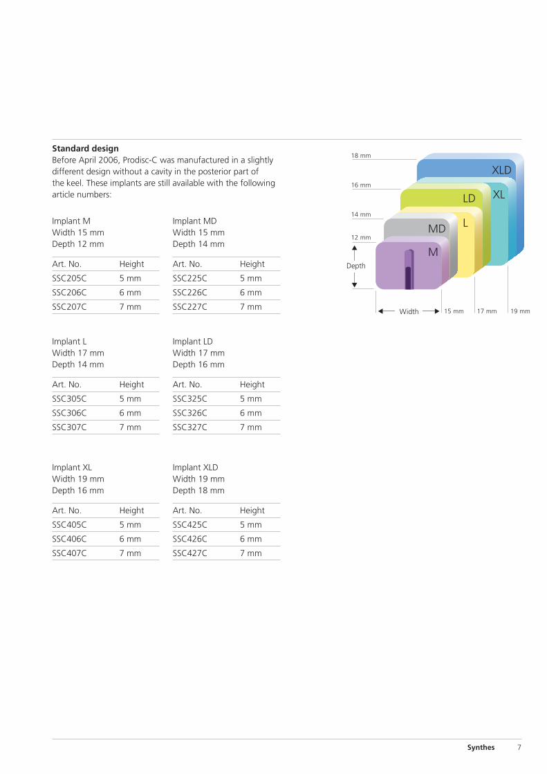
Standard designBefore April 2006, Prodisc-C was manufactured in a slightlydifferent design without a cavity in the posterior part ofthe keel. These implants are still available with the following article numbers:
Implant MWidth 15 mm Depth 12 mm
Art. No. Height
SSC205C 5 mm
SSC206C 6 mm
SSC207C 7 mm
Implant MDWidth 15 mm Depth 14 mm
Art. No. Height
SSC225C 5 mm
SSC226C 6 mm
SSC227C 7 mm
Implant LWidth 17 mm Depth 14 mm
Art. No. Height
SSC305C 5 mm
SSC306C 6 mm
SSC307C 7 mm
Implant LDWidth 17 mm Depth 16 mm
Art. No. Height
SSC325C 5 mm
SSC326C 6 mm
SSC327C 7 mm
Implant XLWidth 19 mm Depth 16 mm
Art. No. Height
SSC405C 5 mm
SSC406C 6 mm
SSC407C 7 mm
Implant XLDWidth 19 mm Depth 18 mm
Art. No. Height
SSC425C 5 mm
SSC426C 6 mm
SSC427C 7 mm
19 mm17 mm15 mmWidth
Depth
18 mm
16 mm
14 mm
12 mm
M
MD L
LD XL
XLD

8 Synthes Prodisc-C Technique Guide
Instruments
The Prodisc-C instrument set was developed for a minimally invasive or microscopic procedure.
03.820.100 Center Punch
03.820.101 Screwdriver
03.820.111 Vertebral Body Retainer
The vertebral body retainer is used to maintain the distraction achieved with the vertebraldistractor. This assures stabilization of thevertebral body for end plate preparation andimplant insertion.
The retainer has a toggle switch mechanism tomaintain distraction as well as compression.
Retainer Screw � 3.5 mm
Art. No. Length of thread
03.820.102 12 mm
03.820.103 14 mm
03.820.104 16 mm
03.820.105 18 mm
Retainer Screw � 4.5 mm
Art. No. Length of thread
03.820.106 13 mm
03.820.107 15 mm
03.820.108 17 mm
03.820.109 19 mm
03.820.110 Locking Nut
03.820.112 Vertebral Distractor
Retainer screw system

Synthes 9
Trial Implant MWidth 15 mmDepth 12 mm
Art. No. Height
03.820.025 5 mm
03.820.026 6 mm
03.820.027 7 mm
Trial Implant MD Width 15 mmDepth 14 mm
Art. No. Height
03.820.035 5 mm
03.820.036 6 mm
03.820.037 7 mm
Trial Implant LWidth 17 mmDepth 14 mm
Art. No. Height
03.820.045 5 mm
03.820.046 6 mm
03.820.047 7 mm
Trial Implant LD Width 17 mmDepth 16 mm
Art. No. Height
03.820.055 5 mm
03.820.056 6 mm
03.820.057 7 mm
Trial Implant XLWidth 19 mmDepth 16 mm
Art. No. Height
03.820.065 5 mm
03.820.066 6 mm
03.820.067 7 mm
Trial Implant XLD Width 19 mmDepth 18 mm
Art. No. Height
03.820.075 5 mm
03.820.076 6 mm
03.820.077 7 mm
Trial implant system
03.820.000 Handle for Trial Implants
The integrated adjustable stop provides a positive stopagainst the anterior portion of the vertebral bodies andcan be adjusted to ensure correct positioning of the trial im-plant.

10 Synthes Prodisc-C Technique Guide
03.820.126 Keel Cut Cleaner
Milling system
The keel cuts are performed with the milling system or withthe chisel instruments as a backup solution. The use of themilling instruments requires a power tool to drive the millingbits.
Milling Guides
Art. No. Height
03.820.114 5 mm
03.820.115 6 mm
03.820.116 7 mm
Milling Bits
Art. No. Type
03.820.117 Synthes
03.820.153 Hex
03.820.155 Step
03.820.157 Cylindric
03.820.159 Flat
Orientation Pins
03.820.136 Orientation Pin, sharp tip
03.820.137 Orientation Pin, blunt
Instruments

Synthes 11
03.820.113 Mallet
03.820.125 Wing for Chisel
03.820.128 Chisel Cleaning Plate
Chisel instruments
The chisels are meant to be a fallback solution, in the un-likely event that the milling system cannot be used.
Chisel, Keel Cutting
Art. No. Height
03.820.119 5 mm
03.820.120 6 mm
03.820.121 7 mm(optional)
Chisel, Box Cutting
Art. No. Height
03.820.122 5 mm
03.820.123 6 mm
03.820.124 7 mm(optional)
The keel cutting chisel, guided by the trial implant, is used tocut channels that lodge the implant keels. The box cuttingchisel is used to prepare the posterior end of the keel cuts forthe optimal insertion of the implant.

12 Synthes Prodisc-C Technique Guide
Position Gauge M
Art. No. Height
SFC252R 5 mm
SFC262R 6 mm
SFC272R 7 mm
Position Gauge MD
Art. No. Height
SFC256R 5 mm
SFC266R 6 mm
SFC276R 7 mm
Position Gauge L
Art. No. Height
SFC352R 5 mm
SFC362R 6 mm
SFC372R 7 mm
Position Gauge LD
Art. No. Height
SFC356R 5 mm
SFC366R 6 mm
SFC376R 7 mm
Position Gauge XL
Art. No. Height
SFC452R 5 mm
SFC462R 6 mm
SFC472R 7 mm
Position Gauge XLD
Art. No. Height
SFC456R 5 mm
SFC466R 6 mm
SFC476R 7 mm
SFC506R Shaft for Position Gauges
Position gauge system (optional)
After the keel cuts have been performed with the milling sys-tem and the trial implant has been removed, position gaugescan be used to check the correct depth and the parallelism ofthe keel cuts.
Instruments

Synthes 13
Insertion instruments
The pre-assembled and sterile packed Prodisc-C prosthesiscan be easily secured on the implant inserter.
SFC602R Implant Inserter, Scissors
Spacer for Implant Inserter SFC602R, radiolucent
Art. No. Height
SFC615R 5 mm
SFC616R 6 mm
SFC617R 7 mm (optional)
03.820.127 Implant Remover (optional)
Spacers for Implant Remover 03.820.127 (optional)
Art. No. Sizes Height
03.820.130 M and MD 5 mm
03.820.131 M and MD 6 mm
03.820.132 M and MD 7 mm
03.820.133 L and LD 5 mm
03.820.134 L and LD 6 mm
03.820.135 L and LD 7 mm
03.820.140 XL and XLD 5 mm
03.820.141 XL and XLD 6 mm
03.820.142 XL and XLD 7 mm

14 Synthes Prodisc-C Technique Guide
The instruments are simple and safe to handle:– Vertebral body retainer for fixing the vertebral bodies – Trial implant with an adjustable stop – Orientation at the midline for precise implanting– The pre-assembled design allows the prosthesis to be
inserted en-bloc – Early mobilization of the patients and short hospital stay
due to minimally invasive access
1. Positioning oftrial implant
Minimally Invasive Access, Simple and Safe
2. Preparation ofkeel cut
3. Insertion of implant

Synthes 15
1Prerequisites and patient positioning
Insertion of a Prodisc-C is dependent on the use of anterior-posterior (AP) and lateral fluoroscopy throughout the proce-dure. Patient positioning should allow for circumferential useof the C-arm at the operative level.
Position the patient in a supine, neutral position on a radio-lucent operating table. Ensure that the neck of the patient isfirmly positioned, using a cushioned but not too soft roll.When treating C6–C7 make sure that the shoulders do notlimit X-ray monitoring. In any case both vertebrae have to becompletely visible.
2Access
Expose the intervertebral disc and the adjacent vertebralbodies through a standard anterolateral approach to the cervical spine. Mark the level of surgery and expose the intervertebral disc segment.
Determine the midline using image intensifier control andmake a permanent midline mark on the superior and inferiorvertebral bodies.
Surgical Technique

16 Synthes Prodisc-C Technique Guide
3Fix retainer screw system
Instruments
03.820.100 Center Punch
03.820.101 Screwdriver
03.820.111 Vertebral Body Retainer
03.820.102–109 Retainer Screws
03.820.110 Locking Nuts
Perforate the anterior cortex in the midline with the centerpunch in the upper third of the superior vertebra and in thelower third of the inferior vertebra. Ensure the spacing of theholes allows for the height of the implant keel.
Insert the retainer screws (� 3.5 mm) into the perforationsand place them bicortically. Their trajectory should be parallelto the adjacent end plate and not necessarily parallel to eachother. Begin with the smaller diameter screw of the longestpossible length. Use a larger diameter screw (� 4.5 mm)when extra bone purchase is needed or as a “rescue” screw.
Note: Insert screws under image intensifier control. Do notperforate the posterior cortex.
Slide the vertebral body retainer over the screws and lock itin place with the locking nuts. This assembly achieves paral-lelism of the retainer screws and the vertebral end plates ofthe operated level.
Surgical Technique

Synthes 17
4Mobilize segment
Instrument
03.820.112 Vertebral Distractor
Start the discectomy using standard instruments.
Under image intensifier control, insert the vertebral distractorto the posterior margin of the vertebral bodies. Distract the intervertebral space with the vertebral distractor in a parallelmanner to restore the height and to gain access to the pos-terior intervertebral space. Do not use the vertebral body re-tainer for distraction but readjust it to the distracted heightof the intervertebral space. Then withdraw the vertebral dis-tractor.
Remove all intervertebral disc tissue and cartilage fragmentsfrom the end plates. Care should be taken to minimize boneremodeling.
Continue the discectomy and decompression.

18 Synthes Prodisc-C Technique Guide
Notes:– Avoid over-distraction with the vertebral distractor as this
can lead to nerve root tension or improper implant selec-tion.
– Avoid using the vertebral body retainer as a distractor. Ex-cessive force on the vertebral body retainer can lead tobending and pull-out of the screws from the bone.
– Avoid excessive end plate removal. Excessive end plate re-moval increases the risk of implant subsidence.
– The uncinatus process should be preserved. If required foradequate bony decompression, the posterior third of theuncinatus process may be remodeled.
– Ensure the cartilageous tissue is removed from the endplates. Cartilageous tissue may prevent osseointegration ofthe implant and reduce the fixation strength.
– Expose the posterior longitudinal ligament to remobilizethe segment. If required for decompression, the PLL maybe resected.
Surgical Technique

Synthes 19
5Insert the trial implant
Instruments
03.820.025-077 Trial Implants (see instruments page 9)
03.820.000 Handle for Trial Implants
03.820.113 Mallet
Trial implants are placed into the disc space intra-operativelyto determine the appropriate implant height and size offootprint.
The goal is to select the largest footprint possible andthe smallest height necessary. The implant should coverthe majority of the vertebral body end plate. Undersized im-plants lead to increased risk of implant subsidence.

20 Synthes Prodisc-C Technique Guide
Connect the trial handle to the trial implant. Ensure that thetrial stop is fully screwed, closest to the footprint. Align thetrial implant on midline and advance the trial implant underimage intensifier control into the disk space.
The optimal position of the trial implant is at the posteriormargin of the vertebral bodies, centered on the midline. Ifthe stop does not allow the trial implant to enter deepenough it can be positioned deeper by turning the adjustablestop anticlockwise (1 rev = 0.5 mm).
Now release the distraction to determine optimal height oftrial implant. Trial height should be the smallest appropriateheight to match normal adjacent discs. Ensure that the trialstop is fully seated against the vertebral bodies, apply mildcompression with the vertebral body retainer and remove thehandle from the trial implant.
Check the position of the trial implant under lateral and APimage intensifier control.
Notes:– Selecting an implant that is too tall can limit the segmental
range of motion. – Clinical experience has shown that in approximately 80%
of all cases the correct trial implant has a height of 5 mm.
Surgical Technique

Synthes 21
6Milling for keel cut preparation
Instruments
03.820.114–116 Milling Guides, Height 5, 6 or 7 mm
03.820.117 Milling Bit, Synthes coupling
03.820.118 Milling Bit, long, Synthes coupling
03.820.153–159 Milling Bits, other couplings
03.820.136–137 Orientation Pins
Choose the milling guide according to the height of the trialimplant.
Slide the milling guide over the shaft of the trial implant andtighten the locking nut. Verify the milling guide is centeredon midline. To ensure construct stability, place the sharp ori-entation pin through the superior hole in the milling guideand manually drive the pin into the bone.
Attach the milling bit with quick coupling to a high-speedpower tool. Under image intensifier control insert the millingbit into the inferior hole of the milling guide and touch theanterior cortex. Under full power, plunge the milling bit intothe vertebral body until it reaches the positive stop in themilling guide.

22 Synthes Prodisc-C Technique Guide
Keeping the drill at full power, sweep the milling bit towardsthe trial implant until it reaches the inner limit of the millingguide, then away from the trial implant to the full outer limit.Remove the milling bit and insert the blunt orientation pininto the inferior hole of the milling guide.
Remove the sharp pin and repeat the milling procedure inthe superior vertebral body. Ensure that the superior keel cuthas the same distance to the posterior border of the vertebraas the inferior keel cut. If the superior keel cut has to bedeepened, a special, longer milling bit can be used.
Notes:– The milling bits should never be used free hand or
unguided.– Synthes recommends single use of the milling bits.– Synthes recommends using the Synthes Electric Pen drive
with 60,000 or 90,000 rpm.
Remove the milling guide. Re-open the vertebral body re-tainer slightly before removing the trial implant.
Surgical Technique

Synthes 23
Option: Chiseling for keel cut preparation
Instruments
03.820.119-121 Chisels, Keel Cutting, Height 5, 6, or 7 mm
03.820.122-124 Chisels, Box Cutting, Height 5, 6, or 7 mm
03.820.125 Wing for Chisel
03.820.113 Mallet
The selected trial implant serves as a guide for the two chis-els and sets the chisel depth. Ensure that the trial stop is fullyseated against the vertebral bodies. The trial stop helps toavoid posterior advancement of the trial implant and chisel.
Slide the keel cutting chisel over the shaft of the trial im-plant. Confirm the chisel is centered on midline and orientedin the sagittal plane. Under lateral image intensifier control,advance the chisel into the vertebral bodies with the mallet.The trajectory of the chisel should remain on midline whileadvancing. Continue advancing the chisel until it is fullyseated on the trial implant.
Ensure that the depth of the keel cuts is equal in the superiorand inferior vertebral bodies. Repeat the chisel procedurewith the box cutting chisel. Again check with the image in-tensifier.
Remove the box cutting chisel. Re-open the vertebral bodyretainer slightly before removing the trial implant.

24 Synthes Prodisc-C Technique Guide
7Clean and check the keel cut
Instrument
03.820.126 Keel Cut Cleaner
Removal of bone material
Use the sharp tip of the keel cut cleaner to remove any bonematerial in the superior and inferior keel cuts. Irrigate andsuction the wound to ensure the disc space is clear of anydebris.
Check the depth of the keel cuts
Insert the sharp tip of the keel cut cleaner at the posteriorend of the keel cuts and check its position under lateral im-age intensifier control.
If the desired position is not reached, insert the trial implantagain and repeat the procedure described in step 6.
Surgical Technique

Synthes 25
Option: Use of the Position Gauges
Instrument
SFCxxxR* Position Gauges
SFC506R Shaft for Position Gauges
03.820.000 Handle for Trial Implants
* different numbers according to size and height
After cleaning the disc space, position gauges can be used tocheck the correct depth and the parallelism of the keel cuts.
Choose the position gauge according to the trial implant(same color coding and height). Screw the shaft to the posi-tion gauge. The shaft can be attached to the handle for thetrial implants.
Correct depth and parallelism of the keel cuts
Place the position gauge at the posterior end of the keelcuts. Make sure that the posterior rim of the position gaugereaches the final position of the Prodisc-C implant.
The distances of both keels to the posterior walls of the ver-tebrae should be identical. Check both under lateral imageintensifier control.
Correct size of the footprint
Judge the size of the footprint with respect to the vertebralend plates. If in doubt, check again with a position gauge ofa larger footprint (width or depth).
Note: The position gauges have precisely the samedimensions as the Prodisc-C implants. Only the keels areslightly narrower, in order not to endanger the press fit forthe implant.

26 Synthes Prodisc-C Technique Guide
8Insert implant
Instruments
SFC602R Implant Inserter
SFC61xR* Spacer for Implant Inserter, Height 5, 6 or 7 mm
03.820.113 Mallet
03.820.101 Screwdriver
* x = corresponds to the height of 5, 6 or 7 mm
Preparation
Spread the distal tips of the implant inserter and install theappropriate sized spacer as determined by the selected im-plant height. Open the implant packaging and place the in-serter in the anterior openings of the implant keels. Makesure that the arm marked “down” corresponds to the infe-rior plate with the PE-inlay. Securely lock the inserter and pullthe implant en-bloc out of the packaging.
Note: The spacer must be fully inserted into the cylindricalpart of the inserter.
Surgical Technique

Synthes 27
Insertion
Align the keels of the Prodisc-C with the keel cuts. Ensurethat the inferior plate with the PE-inlay is caudal.
Under lateral image intensifier control, advance the Prodisc-Cimplant to the posterior margin of the vertebral bodies.
View with the image intensifier
The polymeric part of the spacer is not visible in the lateralview of the image intensifier. A small tantalum marker repre-sents the anterior rim of the Prodisc-C implant.

28 Synthes Prodisc-C Technique Guide
Release the implant inserter from the implant by opening thescissors and remove it by pulling it straight back out of theoperative field.
Step by step remove the securing nuts, the vertebral body retainer and the retainer screws.
Surgical Technique

Synthes 29
Multi-Level Cases
Multi-level Prodisc-C surgeries should be performed level bylevel. The more symptomatic level should be operated first.
In multi-level cases, there must be sufficient bone betweenthe keels of the adjacent prosthesis.
The screws in the upper and lower vertebrae should beplaced in the upper and lower third of the respective verte-bra. The screw in the vertebra in the middle should be placedin line with the others screws, but in the middle of the verte-bra.
If both levels show severe symptomatic degeneration, thediscectomy should be performed on both levels at the sametime. To stabilize the treated segments a trial implant shouldbe placed into one level while mobilizing and preparing thesecond level. The second trial is only used as a spacer; it isnot important to choose the correct size. The three screws tomount the vertebral body retainer are in place during prepa-ration of the disc space and insertion of the implant. Alwaysposition the vertebral body retainer over the segment you arecurrently working on.
If necessary, e.g. with small vertebral bodies, the retainerscrews of the vertebral body retainer can also be insertedobliquely.
Insert the screws under image intensifier control.

30 Synthes Prodisc-C Technique Guide
ExtensionFlexionLateralAnteroposterior
MRI lateralExtensionFlexionLateralAnteroposterior
Case Examples
Case 1: Symptomatic cervical disc disease C5–C7
Patient: Male, 50 years
Symptoms: – Arm pain– Abnormal motor function C7 right (active movement
against resistance)
Diagnosis: – Symptomatic cervical disc disease C5–C7– Osteophytes formation C5–C6 and C6–C7– Disc herniation C5–C6 and C6–C7– Radiculopathy C6–C7– Loss of disc height C6–C7
History: – Arm and neck pain for more than 6 weeks– Physiotherapy, chiropractic and injection without success
Visual analog scale pre-op 6 months 12 monthspost-op post-op
VAS for neck pain 1.5 0.3 1.0intensity
VAS for neck pain 1.5 0.3 0.6frequency
VAS for arm pain 3.2 0.0 0.8intensity
VAS for arm pain 2.9 0.0 0.5frequency
VAS for satisfaction 10.0 10.0
Preoperative
12 months follow up
Synthes 31
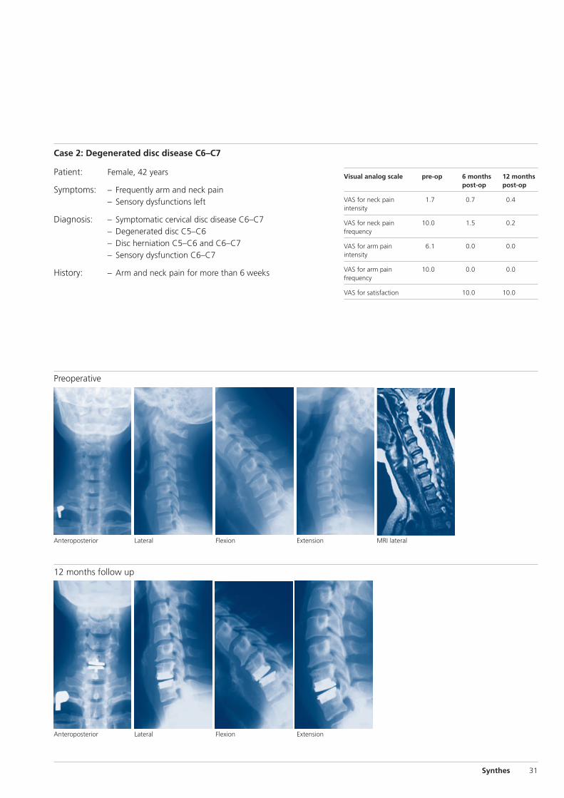
12 months follow up
LateralAnteroposterior
MRI lateralExtensionFlexion
ExtensionFlexion
LateralAnteroposterior
Patient: Female, 42 years
Symptoms: – Frequently arm and neck pain– Sensory dysfunctions left
Diagnosis: – Symptomatic cervical disc disease C6–C7– Degenerated disc C5–C6– Disc herniation C5–C6 and C6–C7– Sensory dysfunction C6–C7
History: – Arm and neck pain for more than 6 weeks
Visual analog scale pre-op 6 months 12 monthspost-op post-op
VAS for neck pain 1.7 0.7 0.4intensity
VAS for neck pain 10.0 1.5 0.2frequency
VAS for arm pain 6.1 0.0 0.0intensity
VAS for arm pain 10.0 0.0 0.0frequency
VAS for satisfaction 10.0 10.0
Case 2: Degenerated disc disease C6–C7
Preoperative

32 Synthes Prodisc-C Technique Guide
Bertagnoli R, Duggal N, Pickett GE, Wigfield CC, Gill SS,Karga A, Voigt S (2005) Cervical total disc replacement, parttwo: clinical results. Orthop Clin North Am 36 (3): 355-62
Bertagnoli R, Yue JJ, Pfeiffer F, Fenk-Mayer A, Lawrence JP,Kershaw T, Nanieva R (2005) Early results after ProDisc-C cer-vical disc replacement. J Neurosurg Spine 2 (4): 403-10
DiAngelo DJ, Foley KT, Morrow BR, Schwab JS, Jung Song,German JW, Blair E (2004) In vitro biomechanics of cervicaldisc arthroplasty with the ProDisc-C total disc implant. Neu-rosurg Focus 17 (3): 44-54
Durbhakula MM, Ghiselli G (2005) Cervical total disc replace-ment, part l: rationale, biomechanics, and implant types. Or-thop Clin North Am 36 (3): 349-54. Review.
Hilibrand AS, Carlson GD, Palumbo MA, Jones PK, BohlmanHH (1999) Radiculopathy and myelopathy at Segments adja-cent to the site of a previous anterior cervical arthrodesis. JBone Joint SurgAm. 81 (4): 519-28
Hilibrand AS, Robbins M (2004) Adjacent segment degenera-tion and adjacent segment disease: the consequences ofspinal fusion? Spine J 4 (6 Suppl): 190S-194S. Review.
Le H, Thontrangan l, Kim DH (2004) Historical review of cer-vical arthroplasty. Neurosurg Focus 17 (3): 1-9
Panjabi M et al (1991) Cervical Human Vertebrae: Quantita-tive Three-Dimensional Anatomy of the Middle and LowerRegions. Spine 16 (8): 861-869
White A, Panjabi M (1990) Clinical BioMechanics of theSpine. J. B. Lippincott Company: 110-111
Yoganandan N, Kumaresan S, Pintar FA (2001) Biomechanicsof the cervical spine Part 2. Cervical spine soft tissue re-sponses and biomechanical modeling. Clin Biomech 16 (1):1-27
Bibliography


0123 036.
000.
431
SE_
0033
51 A
D
5107
0023
©
Syn
thes
20
07
Prod
isc
is a
tra
dem
ark
of S
ynth
es
Subj
ect
to m
odifi
catio
ns
Presented by:


![Comparison of Intervertebral Disc Injuries Caused By ...spine.imedpub.com/comparison-of-intervertebral-disc-injuries... · São Paulo], Escola Paulista de Medicina – UNIFESP-EPM,](https://img.dokumen.tips/doc/110x75/5beff50309d3f2eb288c7518/comparison-of-intervertebral-disc-injuries-caused-by-spine-sao-paulo.jpg)