Embed Size (px)
Citation preview

C.P. No. 1381
. tz PROCUREMENT EXECUTWE, MINISTRY OF DEFENCZ
..P AERilNAUTlCAl RESEARCH COUNCIL
CURRENT PAPERS
The Shear Properties
of Unidirectional Carbon Fibre
Reinforced Plastics and their
Experimental Determination
bY
D. Purslow
Structures Dept., R.A.E., Farnborough Hunts
LONDON: HER MAJESTY’S STATIONERY OFFICE
I977
f3-50 NET

Editor’s Note
The series of Current Papers (CP) of the Aeronautical Research Council will shortly be discontinued.
The series of Reports and Memoranda (R&M) will continue to be publ,ished. Some papers which would otherwise have appeared in the CP Series will be published as R&Ms.

UDC 661.66-426 : 678.046 : 539.415.2 : 539.557 : 620.176 : 620.177.6
*CP No.1381
July 1976
TEE SHEAR PROPERTIES OF UNIDIRECTIONAL CARBON FIBRE REINFORCED PLASTICS AND THEIR EXPERIMENTAL DETERMINATION
D. Purslow
SUMMARY
Various techniques for the prediction and measurement of the shear strength and stiffness of unidirectional carbon fibre composites have been compared and evaluated.
The Report concludes that the shear modulus, but not the shear strength, may be predicted with sufficient accuracy for most practical purposes and recommends satisfactory methods for the experimental determination of shear modulus and strength.
* Replaces RAE Technical Report 76093 - ARC 37132

CONTENTS
INTRODUCTION GENERAL CONSIDERATIONS
2.1 Ideally homogeneous laminates 2.2 Non-homogeneous laminates 2.3 Shear stress distribution
2.3.1 Non-uniform stress 2.3.2 Combined stresses 2.3.3 Stress concentrations 2.3.4 Stability
2.4 Loading rates 2.5 Practical laminates
SELECTION OF TEST TECHNIQUES 3.1 Flat specimens 3.2 Wound or cylindrical specimens 3.3 Angle-ply laminates 3.4 Methods chosen EXPERIMENTAL PROGRAMME 4.1 General 4.2 Plate twist 4.3 Rail 4.4 Short beam 4.5 Transverse compression 4.6 Thin-walled tubes
SPECIMEN MANUFACTURE 5.1 Materials 5.2 Unidirectional flat laminates 5.3 Thin-walled tubes 5.4 Fibre volume fraction and void content THEORY 6.1 Prediction of shear modulus 6.2 Prediction of shear strength RESULTS AND DISCUSSION 7.1 Fabrication techniques 7.2 Modulus measurement and prediction 7.3 Strength measurement and prediction RECOMMENDATIONS
8.1 Modulus measurement 8.2 Strength measurement 8.3 Theoretical predictions
Acknowledgments 29 Tables 1 to 3 30 Symbols 32 References 33 Illustrations Figures 1-45
Page
3
4
4 5 6
6 6 7 7
7 8
8
8 9 9
10 10 10 10 11 13 14 14
16
16 16 17 18
18
18 18
23
23 24 25
28
28: 28 28

3
1 INTRODUCTION
The development of advanced fibre reinforced materials having high specific strength and stiffness has provided the designer with considerable potential for weight saving, particularly in the aerospace field. The advent of these compo- sites has also allowed greater flexibility in the design of such lightweight structures. No longer is it necessary to commence with a known material of specific properties; by selection of fibre and matrix in appropriate proportions the properties of a unidirectional fibre reinforced material may be controlled. Combining laminae of such unidirectional material at differing orientations then allows the production of laminates having the desired strength, stiffness and degree of anisotropy.
A necessary precursor to the effective design of lightweight structures using fibre reinforced plastics is a reliable knowledge of the elastic constants and strength properties of the unidirectional material. Simple determination methods for such properties as shear strength are also useful qualitative tools in
the composite materials development and production fields. Satisfactory tech-
niques for the determination of the properties of isotropic materials have been in existence for many years. The use of highly anisotropic materials, however, has brought the need for new methods of material characterisation and also a requirement for a larger number of material parameters to define fully their characteristics than are necessary for conventional structural materials.
In a series of RAE Technical Reports on unidirectional carbon fibre rein- forced plastics (CFRP) in the form of flat laminates , experimental test specimens and techniques have been described 1-5 for the determination of materials data under longitudinal and transverse tension and compression. A multitude of
methods has been recommended in the literature for the determination of the shear strength and stiffness of unidirectional composites. One of the major problems in shear testing, particularly in the determination of strength, is the influence of stresses other than shear on the properties measured. None of the methods in practice induces a state of pure shear and not all allow determination of both strength and stiffness. The selection of test technique will also be influenced by the method and ease of specimen fabrication and the requirement of any special test facilities. In addition, the plane in which the shear response is required will also restrict the choice of method.
From a consideration of the general conditions necessary for a satisfactory shear test and an evaluation of the available techniques, several of the most

4
promising and applicable methods were chosen for detailed experimental evaluation. This Report describes tests commonly known as 'plate twist', 'rail', 'short beam', 'transverse compression' and 'tube' and investigates their advantages and disadvantages.
Since the above selected methods did not allow the measurement of the 'interlaminar' shear modulus, a simple experiment to determine the relative shear stiffnesses in the three principle planes is also described. The experimental results obtained are presented together with recommendations of suitable test techniques. A discussion of the many theoretical analyses for the prediction of shear modulus and strength results in the recommendation of a simple, accurate method for the calculation of shear stiffness from the constituent material properties. Whilst an effective method of predicting shear strength is not available, the analyses highlight the factors affecting the failing stress.
2 GENERAL CONSIDERATIONS
2.1 Ideally homogeneous laminates
It has been said that the true shear properties can only be obtained when the material is under a state of pure shear'. That this truism needed to be stated is a reflection of how far some common test methods deviate from the ideal. However, taken to the extreme, this statement would preclude any practical determination of the properties of real composites.
In order to understand how the problems arise consider first an ideal laminate: a flat, square, homogeneous plate of uniform thickness and side length (a), subject to an evenly distributed pure shear stress, r , producing a small strain 0 (Fig.1). If the fibre/resin geometry and interaction, and inter- laminar discontinuities are ignored and the unidirectional composite is assumed to be a homogeneous orthotropic material, there are three planes of material symmetry as given in Fig.2. The fibre direction is taken as the '1' axis and the '3' axis is the direction of the laminating pressure; that is to say plane 3 (the plane perpendicular to the 3 axis) is the plane of the laminae. Hence, three planes of shear stress may be defined as longitudinal or in-plane (r12), trans- verse (r23) and interlaminar ('c 13 ) and the corresponding moduli as G 12' '23 and
G13 l
The meaning of these definitions may be clarified by illustrating the strains produced by these stresses (Fig.3). In practice, the longitudinal shear properties govern the design of typical skin construction: the interlaminar shear strength may limit the detailed load transfer mechanism at joints and the bending strength of unidirectional laminates under non-uniform load. Cases where the transverse shear properties are of significance are seldom encountered.
.
*

5
For unidirectional composites, which are the primary concern of this
Report, the shear stresses and strains may be regarded as positive irrespective of direction, but the reader's attention is drawn to the fact that in stress analyses, particularly with off-axis laminates, the use of a sign convention such as that given by Pagan0 and Chou7 is imperative.
2.2 Non-homogeneous laminates
In practice, the above ideal assumption that the laminate is perfectly homogeneous will not be true due to imperfections such as poor lamination, varia- tion in fibre volume fraction and fibre alignment, and voids. For a unidirec-
tional material such a discontinuity will induce what may be regarded as a plane of weakness parallel to the fibres and passing through the discontinuity. Hence under a uniform shear stress T the plate will deform as shown in Fig.4. In a
real material there will be many such discontinuities but only when the strain
4 is small will 6x be small compared to 69, . It follows that such effects
may be ignored when determining the material modulus (i.e. the tangent modulus at zero stress) if the total strain over the length R is measured, If, on the
other hand, the strain is measured over a relatively small area the measured modulus may be lower than the overall modulus if a plane of weakness passes through that area.
These planes of weakness become of considerable importance when discussing the determination of shear strength. When measuring a uniaxial strength such as in transverse tension (a2), the maximum stress may be considered to be that of
the weakest link in a chain where a crack may progress from a discontinuity without hindrance from the loading attachments, In order to apply a similar uniform shear stress to the plate (Fig.4) it is necessary to imagine hypothetical attachments along edges ABCD which allow deformations, 6x , to occur unhindered whilst maintaining a uniform stress along A'D and B'C. Sudden failure would then occur along the weakest line at a stress 2 min which is that of the weakest link.
If the imagination is now turned to equally hypothetical attachments of infinite stiffness such that sides ABCD are constrained to remain straight, deformations such as 6x along planes of weakness cannot take place. The stress along edges A'D and B'C will be non-uniform and a crack originating at a dis- continuity will progress until the redistribution of stress is sufficient to
prevent crack growth or the crack reaches the attachments. In either case there may be no detectable change in sustainable load since, apart from the slight redistribution of stress at the free edges along the crack, even when the crack reaches the attachment the plate A'B'CD merely behaves as two strips A'B'E'F' and

6
EFCD (Fig.4) capable of reacting approximately the same load. The plate will thus continue to sustain increases in load and more cracks until the size and number of strips, n , is such that they fail in bending. At this point elementary bending theory gives the measured 'shear' strength as
and the 'shear' strain as
+ P tan - , 54ET2
(1)
In this case the failure is not due to shear alone, the shear stresses are non-
uniform, ? may be considerably greater than the previously defined ? max min and the material has failed in many places before final collapse,
Practical test configurations provide loading arrangements varying widely between these hypothetical extremes and hence measure shear strengths of signifi- cantly different magnitude, Furthermore it will be clear from the above that the shear modulus and strength will be dependent on whether the stress mode is longitudinal,.transverse or interlaminar and experiments reported here and else- where8 have confirmed that the results from the three modes are different.
Cases also arise where the fibre axes rotate relatively.
2.3 Shear stress distribution
2.3.1 Non-uniform stress
In several test methods, particularly those involving torsion of a solid member, conditions arise where although the stress mode is pure shear, its intensity varies through the specimen cross section. The plastic matrices are rarely, if ever, linearly elastic to failure and hence the measured strain at the surface will not be simply related to the applied load. For the determination of initial modulus acceptable results may be obtained using a simple relationship as long as the stresses are kept very small. Mathematical methods of determining the tangent modulus to failure for non-linear conditions have been evolved' but the results are difficult to interpret. In some cases the shear distribution is hard to determine, making modulus determinations inaccurate and any measured strength of questionable value.
2.3.2 Combined stresses
In most of the available shear test methods, stress modes other than shear are manifest. The question therefore in choosing a suitable method is not so

7
much one of whether shear is the only mode present, but how important is the
presence of another mode. For instance, the existence of a relatively low axial
tensile stress is unlikely to affect the measurement of shear stiffness or strength. On the other hand, in shear tests involving bending, the specimen may fail in flexure before the ultimate shear strength is reached. Similarly, it has been shown1'8 that a relatively small transverse compressive or tensile stress will significantly alter the measured shear strength. In Koyamal' suggest from limited data that the shear modulus varies with compressive stress. Thus the composite shear with transverse stress.
addition, Hayashi and of an epoxy matrix modulus may also vary
2.3.3 Stress concentrations
Whilst in many tests it may be shown that over a relatively large area of the specimen the shear stress is acceptably pure and uniform, concentrations of stress frequently occur, for example, at the edges of the specimen or at the points of load application. In such cases the measurement of strain over the
area of known uniform stress will provide an accurate measure of the shear modulus. However, the stress concentrations may initiate failure at a stress below the ultimate shear strength of the material and thus make the methods of uncertain value for the measurement of strength. This aspect is of particular
importance since many of the simpler tests designed to measure only strength suffer from such effects.
2.3.4 Stability
In cases where the specimen thickness is small compared to some linear dimension, such as in thin-walled tubes or thin flat plates, buckling may influence the determination of the tangent modulus or precipitate early failure. The problem is an inherent one, and can only be accommodated by appropriate specimen design.
2.4 Loading rates
In ancillary experiments 11 to those described in this Report it was shown that little shear stress-relaxation and hence viscoelastic shear strain occurs at stress levels below about one third of the composite ultimate shear strength. However, above this level the measured modulus and strength may be significantly reduced by prolonged or repeated stressing. In order to obtain an accurate measurement of the tangent shear modulus to failure, or simply a reliable strength determination, the loading rate should be such as to produce failure within 3 to
a
6 seconds. For these purposes it is thus clear that manually read, repeated loading experiments are inadequate and automatic load/strain equipment must be employed.
2.5 Practical laminates
The composites tested were fabricated from sheets of resin preimpregnated carbon fibre and hence the test methods chosen had to be applicable to such laminates. The applicability of the methods to material characterisation programmes also means that the cost in terms of material quantity, specimen preparation, and instrumentation and test facility complexity should be minimal consistent with the determination of meaningful properties. This biases the choice of method towards small flat specimens , which for strength determination may be failed in a simple rig in an existing universal test machine and for modulus measurement require only the provision of a strain transducer and recorder.
3 SELECTION OF TEST TRCWIQURS
The shear testing of fibre reinforced materials has been carried out for many years using techniques from the simply crude to the highly elaborate. A literature survey revealed a plethora of existing methods which are best dealt with by tabular summarization (Table 1). Each method is referred to by its most frequently used title and the technique involved represented in the respective illustrations Figs.5 to 7. Minor variations in technique which are not considered significant are omitted. The methods are broadly grouped according to the speci- men geometry. The primary shear mode tested and the suitability for strength or stiffness determination are listed together with a brief assessment of the tech- nique and a column of relevant references.
3.1 Flat specimens
Acoustic and resonance techniques, which appear to offer reliable means of measuring shear modulus, are not considered in this Report since suitable test facilities are unlikely to be generally available. The notch, punch and slip-
plane methods all suffer from serious stress concentrations and specimen preparation for the I beam experiments are considered too elaborate and showed little advantage over other simpler methods. The in-plane deformation occurring in off-axis tension specimens is reckoned to influence the measurement of modulus and, together with the transverse tensile stresses may give a considerably reduced measured ultimate shear strength 6,12-22 . The picture frame technique has been

9
analysed in detail 23 and shown to suffer from serious stress concentration and buckling problems, although Dickerson and Dimartino 24 claim to have overcome some of these using a complicated test rig.
For the measurement of modulus alone, the plate twist test offers most promise if executed within the necessary deflection limits 25-27 ; it also has the advantage that the same specimen can be subsequently tested by other methods and so, for example, allow simple shear strength measurements by the short beam test. It has been shown 28 that the stress concentrations in the rail test are much reduced when conducted with the axis of the fibres perpendicular to the rails and the method may therefore be suitable for the measurement of both strength and modulus. Very significant stress concentrations exist in the short beam specimen and it is not always possible to ensure a shear failure 29-3 1 thus it may provide only a lower limit on the shear strength. At transverse compression test is likely to provide an upper enhancing of the shear strength by the compressive forces
3.2 Wound or cylindrical specimens
Torsion of a solid rod has been used' to measure st
the other extreme, the limit due to the .
ffness and strength but like the beam torsion methods, suffers from non-uniform and usually unknown stress fields. Of all techniques the thin-walled tube with its uniform stress distribution is most likely to give meaningful measurements of strength and stiffness32y33. Although the circumferentially wound tube is to be preferred, for practical fabrication reasons only tubes in which the fibres were aligned axially could be considered.
3.3 Angle-ply laminates
Although there is evidence 34,35 that tension tests on *45' laminates may yield satisfactory values of longitudinal shear modulus, the ultimate shear strengths obtained may be unrepresentative of unidirectional material. Tests of angle-ply laminates were not carried out since they were not compatible with the general set of unidirectional specimens (see section 1).
It should be noted here however that laminated plate theory (e.g. Ashton et a2.36 and Bishop3') f or angle-ply material does give an indication of the significance of the misaligned fibres which occur in a nominally unidirectional laminate. For example, fibres aligned at +5' to the unidirectional material will increase the composite modulus by up to 20% depending on the proportion of misaligned fibres.

lb
3.4 Methods chosen
The selection of methods was based on their compatibility with specimens
laminated from resin preimpregnated carbon fibre sheets, the simplicity of the
method or the closeness of the stress field to a pure shear case. The tech-
niques chosen for experimental evaluation were therefore (1) plate twist,
(2) rail, (3) short beam, (4) transverse compression, and (5) thin-walled tubes.
4 EXPERIMENTAL PROGRAMME
4.1 General
The primary objective of the experimental programme was to examine the
suitability and accuracy of the selected tests for the measurement of the shear
moduli and strengths of unidirectional carbon fibre reinforced plastics. To
minimise possible test variables the specimens were to be fabricated from two
batches only of commercial resin preimpregnated carbon fibre sheet, one batch
using type I and the other type II fibre, both with the same resin system. For
reasons which will become apparent later, a limited number of tests were carried
out using a second high strength resin system.
The shear test methods chosen fall easily into two groupst those using flat
laminates and those using thin-walled tubes. In order to obtain a direct com-
parison between the flat laminate methods, each specimen was subjected in turn to
the plate twist (modulus only) and rail tests (modulus and strength); short beam
and transverse compression strength tests were performed on specimens cut from
areas of the laminate adjacent to the plate twist specimens.
4.2 Plate twist
A square plate loaded as shown in Fig.8 forms the basis of the plate twist
test. If the three supports at A, B and C are fixed, then the deflection,
x , of corner D due to load P has been shown 27 to be given by the
relationship
2 GC=
t3x (2)
where G is the shear modulus,
R is the side length,
and t is the plate thickness.

11
Using classical laminated plate theory Whitney 38,39 has shown that the method is only valid for truly homogeneous orthotropic materials (and 0 + 90" equivalent laminates) and that measurements on +45' angle ply plates are in serious error.
Furthermore, not only is the above relation developed from linear small deflection theory but when the corner deflection exceeds several plate thicknesses
a point of instability will be reached 26 . This instability will be strongly influenced by any initial curvature of the plate. An additional drawback is that the modulus is a function of the plate thickness cubed and hence the thickness must be uniform and accurately known. It should also be noted that the shear stress mode is of a 'rotational transverse' nature.
The experimental set-up is shown in Fig.9. The plate is 70 x 70 x 2mm and is supported at the corners by three domed pillars which are slightly grooved to provide some stability. Corner deflection was measured using a linear transducer and incremental dead weight load was applied via the transducer probe. The
Hewlett-Packard linear displacement transducer (type 7DCDTlOO) was mounted above the plate so that the transducer core rested on the free corner of the plate. The dc output from the transducer was measured using a digital voltmeter. Calibration was undertaken before each test and was accomplished by applying a known deflection using a micrometer mounted above the transducer. A simple, direct conversion from transducer output to corner deflection was thus obtained. The maximum applied load was such that the corner deflection did not exceed lmm (i.e. half the plate thickness). Before testing, a load greater than this
maximum was applied to ensure that any deformation at the corner during test was minimised. Checks were made to confirm that no detectable specimen movement took place at the 'fixed' corners. The tests were repeated three times on each plate and the modulus calculated from the average load/deflection gradient.
Since incremental dead weight loading was used, it was necessary to take 5 second isochronous readings to eliminate creep effects. It may be noted that a useful plate twist rig has been described by Konstantinov and Strelyaev 40 which can be used between the compression platens of a universal test machine.
4.3 Rail
The square plate used in the plate twist test was again employed in the arrangement shown in Fig.lOa. Application of a compressive load P between points A and B induces a shear stress in the specimen. If the angle 0 is made small the shear stress is given simply by

12
P T =Rt
where R is the plate length and t the thickness.
Whilst this test has been widely used 23,28,41-45 it has been subject to criticism from a classical mechanics viewpoint due to the existence of free edges causing non-uniformity in the stress distribution. A detailed Fourier series analysis of symmetrically laminated orthotropic plates by Whitney et al. 28 has shown that in specimens of high aspect ratio (R/b > 10 , Fig.lOa) a uniform stress is found over most of the specimen for all except +45' angle-ply laminates. The analysis also showed that in such a specimen considerable forces perpendicular to the rails occur at the corners CDEF of the test area, For the 0' case, with the fibres aligned parallel to the side supports, the transverse tensile forces are likely to exceed the strength of the material before the ultimate shear strength of the material is reached. With the fibres aligned at 90' the stress is more uniform over the whole area and the stresses perpendicular to the rails
are of little importance relative to the longitudinal strength of the composite. For this reason, most of the tests were conducted with the fibre axes perpendicu- lar to the rails, but a few 0' tests were undertaken to determine the importance of fibre orientation in practice. The stress mode in this case is 'longitudinal'
shear.
The experimental arrangement, a simplified version of that used by Boller 41 , is shown in Fig.lOb. The side supports were of ground mild steel with hardened, square section tips at the points labelled T . The surfaces in contact with the specimen were lined with grade 600 emery paper. Six clearance holes were drilled in the specimen and the clamping bolts tightened to a torque of 25N m. For the high strength material it was not possible to sustain sufficient stress using
emery paper and so metal side plates were bonded to the CFRP specimens: load was applied via the bolts to the side plates. By testing a specimen in which the side plates fitted exactly in the rails and using clamps it was possible to fail a specimen without drilling holes in it. In this way it was shown that the bolt holes in the standard specimens did not affect the maximum sustainable shear stress in the CFEP specimen. One strain gauge was bonded to the centre of each side of the specimen at 45' to the fibre axis thus allowing the effect any bend- ing of the specimen to be accounted for, The specimen was tested to failure between the compression plattens of a universal testing machine at a head dis- placement rate of Imm/min. Aluminium alloy plates between the tips T and the

13
platens allowed some bedding-in to take place and thus alleviated the effects of any slight misalignment. The strain versus load to failure was automatically recorded using strain gauges and an electrical load transducer.
Sims43 describes a 'balanced' rail shear technique in which two identical laminate areas are tested in parallel. Whilst it was considered that the extra complexity involved in this technique was not justified for flat laminates, a modified version employing small cubes of unidirectional CFRP was used to deter- mine the relative shear moduli in the three principal planes.
The test configuration is illustrated in Fig.11. Three aluminium alloy side plates were bonded to the two 1Omm cubes of CFRP as shown. A pair of strain gauges was attached to each block. Load was applied between the compression platens of an Instron test machine, the roller being inserted as shown to mini- mise the effects of any slight misalignment of the side plates. Load-strain curves, up to a maximum stress of O.SMN/m*, were recorded automatically. The test was carried out three times with the fibre axes in each of the three
principal planes. Similar tests were carried out on resin blocks of the same size.
4.4 Short beam
This well known method 5,46 , illustrated in Fig.12 is based on the fact that in some cases, a beam loaded in three-point flexure may be made to fail in 'interlaminar' shear at the neutral plane before the outer fibres break in tension or compression. A number of investigations *g-31,47,48 of the effect of specimen geometry on the measured strength have been made and for CFRP the recommended' span/thickness ratio is five, but even at this ratio composites of low fibre strength or high interlaminar shear strength may fail prematurely in flexure 49,50
l
Whilst this test is economical of material and simple to perform there is a number of drawbacks. The principal drawbacks are that the stresses are non- uniform, even in the plane of the laminate, that states of combined stress exist and that severe stress concentrations arise at the points of load applica- tion29-31,49 . Classical beam theory gives the relationship for shear stress T as
3P T = bbt (4)
where P is the applied load and b and t are the width and thickness respectively.

14
However, it has been shown2g'31 that the assumptions on which this theory is based do not pertain to the short beam test. A finite element analysis by Berg 29
has shown that due to stress concentrations in the region of the loading points, the maximum shear stress does not occur at the centre of the beam and that the method may significantly underestimate the true maximum shear strength. Similar conclusions have been reached by Sattar and Kellogg 31 using a distortion energy failure criterion and an exact theory of elasticity solution, although the pre- dicted reduction in measured strength for the RAE specimen in this case is only about 8%. However, even this theory is inadequate 51 since it assumes there are no end effects (T must be zero at the ends); also equation (4) assumes a
linearly elastic stress-strain relationship which is in general not true. As 11 previously noted , the measured shear properties are also dependent on the rate
of loading. In this particular test the measured strength has been shown 52,53
to drop with very rapid loading and it is thought that this results from the fact that the stress concentrations discussed above do not have time to dissipate plastically.
Despite these drawbacks it is a simple, reproducible test, useful for qualitative evaluation and likely to provide a satisfactorily accurate measurement of 'interlaminar' shear strength.
The method has been adequately described elsewhere 5,46 and the dimensions are given in Fig.12. The specimens were tested to failure in the Instron universal machine at a head displacement rate of Smm/min (see Ref.11).
4.5 Transverse compression
Rosen and Dow 54 suggested that a block compression test of unidirectional material transverse to the filaments would yield more representative quantitative values for shear strengths than short beam tests. As previously noted, the presence of transverse compressive forces has been shown1 to significantly increase the measured composite shear strength in the (2,3) plane (see Fig.3). However, since the test is so simple and economical of material it was considered worthwhile examining , since at least it would give an upper limit to the value of shear strength, albeit in the 'transverse mode'. The specimens were approximately 5 x 3 x 2mm (see Fig.5) and were tested between the compression platens of a universal test machine.
4.6 Thin-walled tubes
It is generally accepted that, from the applied mechanics aspect, the use of thin-walled tubes provides not only the most satisfactory method of determining

15
the ‘in-plane’ shear properties but also a specimen configuration suitable for
general composite materials characterisation. If the ratio of tube radius to
wall thickness is sufficiently large and one end of the tube is free to move in
the direction of the tube axis as well as rotate, a reasonably pure state of shear
stress has been shown to exist 15,32,33,55 . One disadvantage is that the modulus
is a function of the fourth power of the internal and external tube diameters
(see equation (5) following) , so that care in tube manufacture and measurement is
necessary. Many workers have used filament wound tubes since the constraining
end-attachment effects on strength discussed earlier (section 2.2) do not arise,
but such a method of manufacture is unlikely to produce results representative of
the properties of flat laminates fabricated from resin preimpregnated sheet. It
was therefore necessary, as shown in the subsequent description of specimen
manufacture, to use tubes with the fibres aligned parallel to the tube axis as
the nearest approximation.
The dimensions of the tube are given in Fig.13; the thickness to radius
ratio of 1:12.5 is subsequently shown experimentally to be adequate. With rigid
end fixings Rizzo and Vicario 56 have shown theoretically that serious stress
concentrations may arise in the region of the end attachments. In an endeavour
to alleviate this problem the use of epoxy end fittings to allow some deformation
to occur within the gripped length was investigated. The design of the end fit-
ting is shown in Fig.13 and consists of 25mm thick, 9Ourn diameter epoxy* blocks
together with a 2.5mm thick aluminium alloy facing plate. The end was cast with
12.5mm of the tube within the block. This allowed sufficient shear transfer area
from the block to the tube and the metal plate distributed the load uniformly
from the attachment bolts. A long (3OOnrn) CFRP tube of similar cross section was
fabricated and strain gauged at intervals between the centre and one end. Epoxy
end fittings were cast on and the initial modulus measured at each gauge position
and acceptable agreement between gauges obtained. The length of the tube was then
reduced in stages so that the end gauge lay first close to the end fitting and was
then embedded in the epoxy. The moduli at the exposed gauge positions did not
change significantly and the strain registered by the embedded gauge was reduced
to approximately 15X of the exposed gauges. It was thus apparent that some shear
strain was able to occur within the embedded region and that this rose to the
test section value without significant stress concentrations. This also resulted
in a tube length considerably shorter than that considered necessary by Pagan0
and Whitney 55 .
* CIBA HY753/Hy951 (1051, by volume) .

16
The final design assembled in the test rig is shown in Fig.14a and b.
A tensile load applied to the rig by the Instron universal testing machine was
converted by the lever system to a pure torque. The tube end to which the moment
was applied was also free to move axially and so allowed the small amount of
longitudinal contraction which takes place to occur unhindered, To ensure that
the rig was inducing no bending, one tube was tested with six strain gauges
located round the central circumference: no detectable difference in strain was
observed. A similar exercise with internal and external gauges showed no
measurable strain gradient through the wall thickness.
The strain from a pair of diametrically opposite 45’ gauges was automatic-
ally recorded by the servo chart drive system as the specimen was loaded to
failure, the ultimate stress being reached within approximately IO seconds. The
shear stress =12 was calculated from the expression
1 6de
r12 = n(d; - d;)
x torque (5)
where d and d. e 1 are the external and internal diameters respectively.
5 SPECIMEN MANUFACTURE
5.1 Materials
In order to eliminate batch to batch variations it was important that the
same batches of resin impregnated carbon fibre sheet were used for all the tests.
The actual material used in the progranrne was governed by the fact that it was
the only material available at the time. The material properties are listed in
Table 2. The sheets supplied were approximately lm long in the direction of the
fibres, 0.3m wide, 0.25mm thick and contained about equal parts by weight of
fibre and resin.
5.2 Unidirectional flat laminates
The sheets were press-moulded to produce boards 2OOmm long (in the fibre
direction), 9Oam wide and about 2mm thick. The fibre volume fraction of the
prepared boards was varied between 0.45 and 0.7 by increasing the number of plies
and the applied pressure. The laminate was inserted in a press, preheated to
160°C and the pressure increased in stages. After moulding the board was post
cured in an air-circulating oven at 16O’C. The boards were ground flat and to a
uniform thickness; two 7Omm square and several 12.5 x 10 and 5 x 3mm specimens
were cut from each board and the edges ground smooth and square. The square

17
plates were used first for the plate twist tests. They were then drilled, as in Fig.15, and tested to failure in the rail shear rig. Since it may be anticipated that peak stresses will arise near the free ends of short beam specimens 29 , care was taken to minimise local stress concentrations by grinding smooth the cut faces.
A number of 2mm thick type II fibre and 1Omm thick type I fibre specimens 57 were fabricated by an autoclave process . The material properties are listed in
Table 2 and the specimens identified throughout the report by the prefixes AC .
5.3 Thin-walled tubes
For many torsion tests on thin-walled tubes the method of fabrication is that of filament winding. However, such a method is unlikely to produce composites whose properties reflect those of flat laminates. It was therefore necessary to fabricate the tubes from the same batch of sheets as the flat laminates. A tube with circumferential fibres fabricated from sheet would obviously have a dis- continuity on the inner and outer surfaces. The effect of these discontinuities could be reduced by using a large number of plies but this would necessitate a relatively large diameter and an increase in material cost. In addition, laminat- ing pressure applied either externally on to a male former or internally into a female former had been found in preliminary investigations to produce poor quality tubes. In neither case are the fibres able to move radially; in the first case compaction results in misaligned fibres, while in the second case the fibre volume fraction varies from high (with associated resin starvation) at the inner surface to low at the outer surface. Only by elaborate heating and pressuriza- tion at the time of winding could a reasonable composite be obtained. It was therefore evident that the fibres would have to run parallel to the tube axis and it was considered that high quality tubes could be obtained more readily by expanding a metal mandrel into a metal cylinder than by the male mould/external pressure technique. Further, fabrication by hot moulding around a fixed male mandrel33 results frequently in cracking of the laminate due to resin contraction during cooling. The moulding rig used in this programme is illustrated in Figs.16 and 17. The eight-segment mandrel is covered with rubber tube and, by simultane- ously screwing bolts A and B, the tapered rods C and D expand the mandrel within the outer tube. This tube is accurately positioned by blocks E and F, the tapered rods making a sliding fit in the blocks so that the expanding mandrel remains concentric with the mould tube throughout expansion of the mandrel. The blocks were drilled as at G to allow excess resin to exude. By variation of the wall thickness of the outer metal tube, the thickness of the CFRP tube may be altered.

The resin preimpregnated carbon fibre sheet was cut to the appropriate size and the plies laid up in a stepped manner. The size of the steps, which allowed the material to be wrapped around the unexpanded mandrel without overlap, was deter- mined empirically. The rubber covering of the mandrel was coated with release spray, the plies wrapped around the mandrel and inserted, together with an outer layer of release paper, into the outer metal tube. The tube was then located between the blocks and the tapered rods inserted until they just engaged in the mandrel. The whole rig was put into an air circulating oven at 120°C until it reached a uniform temperature. Bolts A and B were then tightened until the mandrel was fully expanded and the laminate was finally replaced in the oven at 1'60°C and allowed to cure for 14 hours.
The laminated CFRP tube was then supported with its axis accurately perpendicular to, and one end 15mm above the centre of, the base of a 9Omm diameter open mould. A 2.5mm thick aluminium alloy plate was placed in the mould and epoxy resin poured in until the level reached 12.5mm up the CFRP tube. The resin was allowed to cure at room temperature and a similar epoxy fitting was
cast on the other end of the tube. The end fittings were then drilled for attachment to the torsion rig.
The expression for the shear stress has been seen to be a function of the fourth power of the tube diameter and thus small uncertainties in measurement could introduce large errors in the stress , and hence in the calculated modulus. Because very small thickness variations inevitably occurred, the internal dia- meter was calculated after failure from the measured outside diameter and the volume (by Archimedes principle) of an exact length of tube. Since fabrication was costly compared to that of flat laminates, only tubes of a nominal 0.65 fibre volume fraction were prepared.
5.4 Fibre volume fraction and void content
The fibre volume fraction Vf and void content Vv of each specimen were determined from small samples of the tested specimens by a wet combustion and
58 density column technique as described by Ewins and Childs .
6 THEORY
6.1 Prediction of shear modulus
A comprehensive review of the numerous approaches to the prediction of elastic constants of composite materials, including shear modulus, has been given by Ashton et aZ. 36 and will not be repeated here. Most of the solutions involve
19
extensive computational operations and are therefore unsuitable for 'desk' calculation. Using a finite difference method involving a doubly periodic rectangular fibre array Adams and Doner 59 have produced a solution which is in good agreement with published experimental data for both carbon and glass
60,61 reinforced plastics .
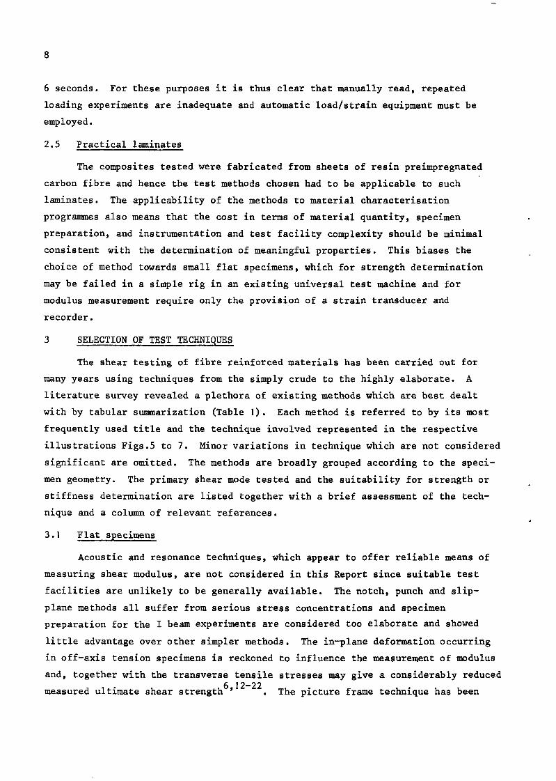
The methods of Halpin and Tsai 14 and Hashin and Rosen 62 may however be reduced to simple forms. The Halpin-Tsai equation gives the relationship between composite and matrix shear modulus as
GC (1 + 6rlVf)
K= (1 d Wf) (6)
where n =
the reinforcement constant 6 is assumed to be unity, and suffices c, f and m refer to the shear moduli of composite, fibre and matrix respectively.
If Gf B-G m the expression reduces further to
GC
G, e
1 + Vf 1 -vf l
The results of equation (6) give estimates of shear modulus which agree with experiment only up to fibre volume fractions of 0.5. In order to obtain a simple solution which approximates to the lengthy analysis of Adams and Doner 59 , Hewitt and de Malherbe 63 have proposed, without theoretical justification, modifying the Halpin-Tsai equation so that
(7)
6 = 1 + 4ovy .
Sendeckyj 64,65 has produced an exact solution which, whilst it is complex for the general case, reduces to the following simple expression for a square array
GC
K= (9)

20
where A = ?-IV f and 6 I. =
Sendeckyj also shows that equation (9) gives results in excellent agreement with his more exact solution. It may be noted that if only the first term in brackets is retained the expression becomes identical to equation (6).
The above equations all express the composite shear modulus in terms of the fibre and matrix shear moduli and the fibre volume fraction of the composite. Values of fibre volume fraction and matrix shear modulus may be readily obtained by experiment; although it has been suggested by Schrager and Carey 66 that, due to stress concentration effects, assuming the matrix modulus in the vicinity of the fibre to be that of the bulk material may be erroneous. Investigation of the
67-69 micro-structure of carbon fibres has shown them to be highly anisotropic with a radial variation of basal plane alignment which will almost certainly cause a corresponding variation in shear modulus, However, assuming the fibres to be transversely isotropic, Dean and Turner 70 have derived the elastic proper- ties of fibres in an epoxy matrix composite. Using an ultrasonic pulse trans- mission technique the composite moduli were determined for various fibre volume fractions. From the Halpin-Tsai equation (6) they were able to work back to an estimate of the fibre moduli. The longitudinal fibre shear moduli so obtained of between 14 and 26MN/m2 were similar to those assumed in previous analyses 59,64,71 . Heaton7* and Whitney72 have shown the calculated composite shear moduli to be significantly lower when fibre anisotropy is introduced, It is fortunate therefore that a reasonable estimate of the composite shear modulus is not dependent on an exact knowledge of the appropriate fibre modulus. For instance, using equation (6) a large error in fibre modulus assumption (say 20 instead of 3UMN/m2) for a 0.6 fibre volume fraction composite using a typical resin
CGm = IMN/m2) produces only a 5% change in composite modulus.
A comparison of the various methods for a typical carbon fibre/epoxy composite is given in Table 3 and Fig.18. It can be seen that the Hewitt and
de Malherbe Adams and DIIer5'.
empirical equation is in acceptable agreement with the analysis of The equations of Halpin-Tsai 14 .64 and SendeckyJ produce
significant underestimates of the shear moduli at fibre volume fractions above 0.5 and since CFRP is unlikely to find much application at fibre concentrations
below 50%, these methods are of limited practical use. Using equations (6) and (8) the modulus variation with fibre volume fraction was calculated for two typical resins. The curves are plotted in Fig.19.

21
Since the composite shear properties are largely determined by the properties
of the matrix it is to be expected that any variation of matrix shear modulus with
void content would incur a corresponding variation in composite shear modulus.
Jones and Noyes 73 summarize the various approaches to the prediction of the
effect of voids on the matrix shear modulus. The following expression deduced
analytically was selected by Jones and Noyes and provided best agreement with
existing test data,
--I-p “mV
Gm 1 + pb (10)
where b = 2(4 - 511) 7 - 5u
P is the matrix void volume fraction
and lJ is Poisson’s ratio (assumed here to be 0.3).
The above equations lead to the prediction that for an epoxy-matrix composite of
0.5 fibre volume fraction containing a composite void content of 1%
(i.e. p = kO.02 and b fi 0.91) the matrix modulus will be reduced by about 4%
causing a similar reduction in composite shear modulus.
6.2 Prediction of shear strength
Although an improved understanding of basic failure mechanisms has been
obtained from a number of analyses (see, for example, Ref.74), the reliable
prediction of ultimate shear strength from the constituent material properties
has yet to be accomplished. The three basic parameters affecting the shear
strength of a high quality unidirectional composite are the ultimate shear
stresses sustainable in the fibre, in the matrix and at the interface. Hashinir5
suggests that a lower bound for a void free, well-bonded composite is the shear
strength of the matrix (TV). An upper limit of 4/x x rm , as Vf + 1 has been
proposed by Shu and Rosen76. Using the hypothesis that the shear strength is
limited by the allowable matrix shear strain, Chamis 77 has derived the following
semi-empirical relationship for shear strength:

22
B, = (void correction) .
Assuming the variables such as void size and distribution, filament spacing and uniformity, interface bond strength, and residual stresses are approximately invariant for a particular fabrication process, he suggests all these may be grouped into a theory/experiment correlation factor Bs . 4, is the limiting matrix shear strain. For a void free, well laminated composite the theory- experiment correlation coefficients $
8 and f3 v approach unity. For the case
where the fibre interface is the weakest link, Noyes and Jones 78 have suggested a semi-empirical formula of the form
(12)
where T and T C m are the shear strength of the composite and matrix
respectively.
A number of investigations has been undertaken to determine the magnitude of the stress concentrations in a matrix caused by the presence of the ~~~res~~~6~~6~~~~ . The stress in all these cases is a maximum at the points on the fibre/matrix interface closest to adjacent fibres. The results of Adams and Doner5' (which are similar to those of other workers) are given in Fig.20 for a square array with Gf/~ = 20 , It can be seen that at higher fibre volume fractions approaching Om7 the stress concentration factor rises rapidly. Reynolds and Hancox" have investigated the relationship between composite shear strength and fibre/matrix bond strength in terms of fracture mechanics theory. Their
experimental results and empirically determined stress concentration factors confirm the trend predicted by Adams and Doner 59 .
From the above considerations it is possible to predict that for a composite in which the interfacial bond strength exceeds the yield strength of the matrix, the composite shear strength will fall by up to 50X as the fibre volume fraction,
"f 9 is increased from 0 to 0.65 (see Fig.20). As Vf approaches 0.7 the rapid increase in stress concentration factor will cause a corresponding fall in shear
strength. For composites with a bond strength weaker than the matrix the reduc- tion in strength with increase in fibre volume fraction is likely to be more rapid. Scanning electron micrographs of fractured shear specimens by Novak
81

23
tend to confirm these predictions and also to indicate that the way in which the crack propagates in composites of increasing strength produces increasingly brittle failures.
Noyes and Jones 78 have also investigated the effect of voids and derived
the following expression
T V
Tm
= l Al-+J (1 + Vf)
where 'c V
is the shear strength of the voidy composite
P is the void volume fraction in the matrix and B is an empirical constant.
For the case of spherical voids in a cubic array, Greszczuk 82 has derived the following equation for the ratio of voided to unvoided shear strength:
+r 6V t V 7T - = I--
f [ I
4 Tf(1 -vvf) '
(13)
(14)
Experiments for glass/epoxy composites were said to be in good agreement with the theory over a wide range (0-23.X) of void contents. Other empirical equations have been derived by Brelant 83 , Hand 84 85 I and Kohn et al. .
The variations of shear strength with void content predicted by Chamis, Noyes and Jones (assuming arbitrarily B = 12) and Greszczuk are plotted in Fig.21. Also plotted are experimental results by Stone and Clarke 86 for a high shear modulus and strength carbon/epoxy composite.
7 RESULTS AND DISCUSSION
7.1 Fabrication techniques
At the beginning of the experimental programme described in this Report the then current method of laminate production was by press-moulding. It will be seen in the following sections that this technique sometimes produced laminates with high void content (up to 12%) and mechanical properties which varied
significantly between nominally identical specimens. In addition, the shear stress-strain relationship showed considerable nonlinearity throughout the stress range aud high strain to failure. These factors have a particularly marked effect on the measurements of shear strength and its variation with volume fraction (section 7.3).

24
For this reason a limited number of laminates were subsequently prepared using the autoclave process 57 , providing specimens of uniform high quality and
low void content (V, < 0.5%). A limited range of fibre volume fractions is obtainable using this process and hence measurement of the variation of shear modulus and strength with fibre volume fraction was not undertaken on the auto-
clave material.
7.2 Modulus measurement and prediction
The results are presented in Figs.22 to 30 where, for clarity, only the mean figures for bands of fibre volume fraction Vf + 0.25 are shown. The curves represent the predicted modulus for void-free specimens derived from equation (8) (section 6.1). Typical stress-strain curves for the rail and tube tests are shown in Figs.27 and 28.
Considerable scatter in the measured modulus is evident, particularly in the type I composites. However, by comparing the results for the plate twist and rail tests, Figs.22 to 25, it can be seen that in general the results are similar and hence the scatter is a reflection of the variation of material properties and not of the method of test. It can be seen that most of the modulus variations occur above the predicted values and these higher stiffnesses
obtained by experiment may be due to the presence of a considerable proportion of misaligned fibres (section 3.3). The greater variability of the type I fibre composites may be attributed to the poorer quality of the laminates which have an average void content (6.3%) twice that of the type II material. The laminates for both type I and type II composites were prepared by the same standard press-moulding technique and the difference in quality may be due to the facts that with type I material, fibre breakage during fabrication and fibre 'springback' after lamination are more likely. Some scatter may also arise with both types of fibre composite due to the difficulty in obtaining precise measure- ments of fibre volume fraction and void content.
The differences between the plate twist , rail and tube modulus measurements are in general small and random - some variation between methods is likely to arise from the different shear modes and fabrication techniques involved. Of the rail results it may be noted that the 0' measurements are slightly higher than those taken at 90'. It is thought that this is a reflection of the difference in stress distribution between the two methods (section 4.3). Referring to the results of the 90' rail measurements on type II laminates which show least scatter
(replotted for clarity as Fig.29) it may be seen that the agreement between

25
experiment and theory is good up to 0.65 volume fraction. The lower measured
modulus at fibre volume fractions approaching 0.7 may be the result of the stress concentration factors discussed in section 6.2 and the larger significance of voids at high fibre volume fractions.
The magnitude of the void content corrections (section 6.1, equation (10)) is obviously too great. The analysis underlying equation (10) was based on an assumption of a regular cubic array of spherical voids within the composite. Microscopic examination of the materials shows that in material with void content greater than 1.5% (section 7.2) the majority of voids occur as large inclusions between laminae (see Fig.32). Voids such as these would be expected to have a much smaller effect on the longitudinal shear modulus than on the interlaminar shear stiffness.
The relative shear stiffnesses in the three principal directions are shown in Fig.30 for the AC type I fibre composites and it can be seen that all the moduli, including that of the resin, are less than expected. This is thought to be the result of the non-uniformity of shear strain across the very small test area, the strain being measured over an area subject to above-average shear stress. However, it is unlikely that such an effect would greatly alter the relationship between stiffnesses. For the volume fractions tested the longi- tudinal, interlaminar, transverse and resin shear moduli are in the ratios 1:0.85:0.42:0.25 respectively.
7.3 Strength measurement and prediction
The strengths are plotted as a function of fibre volume fraction in Figs.33 to 38 and as a function of void content in Figs.39 to 44. The individual strength measurements of the 90' rail tests are given but for the short beam and transverse compression tests each point is the mean of six and two tests respectively. Results of 0' rail tests are given in Fig.36 for comparison. In an attempt to separate the effects of fibre volume fraction and void content on strength, both relationships were assumed to be linear up to 0.68 fibre volume fraction and a partial regression analysis was performed for fibre volume frac- tions below 0.68, the results being shown as solid lines in Figs.39 to 44. The results above V f = 0.68 , were however omitted from the regression analysis since stress concentration effects caused the measured strengths to depart rapidly from the general trend (see Fig.20). In Figs.33 to 38 the variation of strength with fibre volume fraction is given for average and zero void contents and in
Figs.39 to 44 are given the variation of strength with void content for a fibre

26
volume fraction of 0.6. In every case the strength increases with increase in
volume fraction (up to 0.68) - the opposite trend to that predicted (see
section 6.2). Microscopic examination of failed specimens showed large deforma- tion to have occurred in resin-rich areas, indicating considerable plastic flow in the matrix; this fact is reflected in the low composite yield stresses and high strains to failure,
It must therefore be concluded that the matrix showed considerable non- linearity in its stress-strain behaviour at stresses well below the interfacial bond strength, Under these conditions the variation of stress concentration factor with volume fraction is likely to be closer to unity than that shown in Fig.20 for fibre volume fractions below about 0.65; the high void content would
reduce the shear strength at all fibre volume fractions. The presence of
increasing amounts of fibre might therefore produce an increase in strength as predicted by Shu and Rosen 76 (see section 6.2); enhanced by the large proportion of misaligned fibres (Fig.31). The results from these press-moulded specimens serve to accentuate, and therefore highlight, the differences in the strengths, and the different shear modes, obtained from the various test methods. Fig.45 compares the variation of shear strength with fibre volume fraction of type II composites (Vv =0) as determined by the several techniques. This variation between techniques may well be attributed to the difference in boundary conditions
discussed in section 2. The short beam test, with no constraint on shear deflec- tion and significant stress concentrations , provides a lower limit on the shear strength. The uniformly stressed tubes , with little restraint from the end fittings show a somewhat greater failing stress. A crack initiating in the tube test section may progress catastrophically along the length of the tube, due to the comparatively low stiffness and strength of the epoxy end fittings. Examina-
tion of the failed tubes showed that in every case both end fittings failed at the line of the tube failure. If the stress/strain curves to failure for tube and 90' rail tests are compared (Figs.27, 28) it will be seen that not only is the measured rail strength higher but the strain to failure is also greater. This may be a direct reflection of the rigid constraint imposed along the edge of the specimen. A similar argument, together with the increased significance of stress concentrations , would account for the lower strength determined by the 0' rail test, Fig.36. The high shear strengths derived from the transverse com-
pressive test were expected due to the effect of transverse forces on the shear strength',

27
The results of the tests on high quality autoclave specimens are shown in
Fig.45 and are the means of six tests each. The discrepancies between the
strengths measured by the three methods may be in part due to the relative size of the test specimens in that larger specimens are more likely to contain an area of reduced strength. This concept is supported by the larger scatter
evident within a given laminate in the strengths measured by the transverse compression tests. The slight shear stress concentration (SCF fi 1.1, Ref.28) near the free edges of 90' rail specimens may account for the somewhat lower strengths measured by the rail test.
Comparing the effect of voids on the composite shear strength determined experimentally with the theoretical analyses (Fig.21) it is evident that for-the low strength composites, as with the modulus variation, the measured reduction is less than predicted. Little significance is attached to this in view of the poor strength of these composites. The more evenly distributed voids observed by Lenoe87y88 and Kohn et aZ. 85 had an effect approximately that predicted by
The tests on high quality, high strength composites by Stone and Clarke 86
show that up to void contents of about 1% the reduction in shear strength due to voids is somewhat less than that predicted (see Fig.21). At low void contents (< 0.5%) there is considerable experimental scatter due to the difficulty in
obtaining void content measurements of sufficient accuracy, while other parameters such as fibre misalignment have greater significance. As the void content increases beyond 0.5%, their presence becomes increasingly important until at 2% the strength has dropped by 35% - about twice the fall predicted by Chamis 77 and Greszczuk82. Above 2% the fall in strength becomes less rapid.
Microscopic examination shows that up to 1.5% void content the voids are generally small and randomly distributed such as would be caused by trapped volatiles. Above 1.5%, larger voids occur between laminae and are usually formed
by air trapped adjacent to misaligned fibres on the surface of a laminae and not removed during the cure cycle. These large voids may cause a drastic reduction in interlaminar shear strength. It will be evident that the strength of a short beam specimen containing one relatively large interlaminar void will not be greatly reduced by the presence of a second void between a different pair of laminae. Hence the rate of reduction in strength might be expected to decrease above about 2% void content.
28
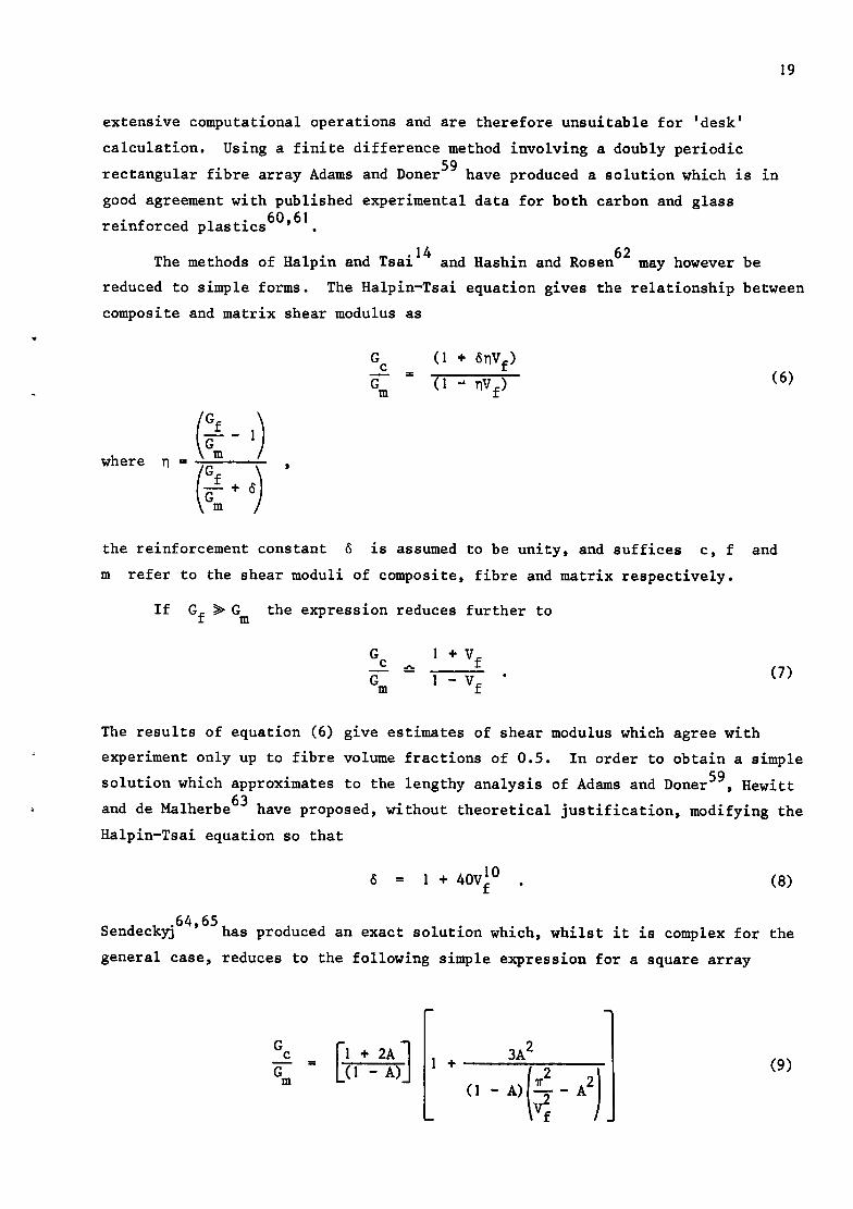
8 RRCOMMRNDATIONS
8.1 Modulus measurement
As far as measurement accuracy is concerned there is little to choose
between the plate twist, rail and tube tests. Within the deflection constraints
of the method, the plate twist test is simple and does not necessitate individual
strain transducers for each specimen; but the laminates must be flat and the
thickness uniform and accurately known. It should also be remembered that the
shear mode in the plate twist test is ‘transverse rotational’ and not ‘longi-
tudinal’ . Both rail and tube tests give accurate assessments of longitudinal
shear moduli but in general require strain measuring equipment. Where a know-
ledge of the ‘interlaminar’ or ‘transverse’ modulus is required the modified
rail test on thick laminates (section 4.3) may be employed. If the ‘longitudinal’
shear modulus is accurately known (e.g. from the standard rail test) and is also
determined using the modified technique, allowance may be made for any under-
estimation of the interlaminar and transverse moduli (section 7.1).
The viscoelastic nature of epoxy matrix composites (section 2.4) must be
emphasised, particularly when determining the modulus to failure which should
occur within 6 seconds of the commencement of loading.
8.2 Strength measurement
It has been shown (section 2) that not only is the measured shear strength
of a particular type of composite dependent on the shear stress mode and its
uniformity but also, for low modulus materials, on the amount of edge constraint
applied. The tube technique as described in this Report probably gives the most
accurate estimate of shear strength and is particularly recommended for low
modulus materials. However, it is an expensive technique relative to the others
described and where the longitudinal shear modulus to failure is required the
rail test has been shown to be a suitable alternative. Short beam and transverse
compression tests will give simple and reliable estimates of the ‘interlaminar’
and ‘transverse’ composite shear strengths if carried out correctly. The trans-
verse compression test is also useful for composites whose shear strengths are
very high and which do not fail in shear under short beam test conditions.
8.3 Theoretical predictions
The predicted shear modulus using equation (8) (section 6.1) agrees well
with the experimental results presented in this Report and elsewhere and may be
used for most unidirectional carbon fibre composites that may be envisaged. In

29
addition, it is worth noting that the simple expression of equation (7) gives results of sufficient accuracy for many purposes.
Further investigation is necessary before the prediction of shear strength from the constituent material properties is possible. The knowledge to date highlights the importance of the matrix and fibre/matrix interface properties.
The methods for predicting the effect of voids on the shear properties are also not yet sufficiently accurate to recommend their use.
Acknowledgments
The contributions of a number of Departmental colleagues in particular, Mr. R.T. Potter are gratefully acknowledged.

Table 1
SUMMARY OF SHEAR TEST TECHNIQUES
w 0
Specimen onfiguration
Thin beam
Thin plate
Thick beam
Wound or cylindrical
Cro55ply
Figure
5b
SC
5d
5a
Similar to SC
se
5f
6a
6b
6d
6c
7a
Similar to 5b
7b
Similar to 7b
Similar to 5d
7C
7d
Shear mode
Interlaminar
Transverse*
Longitudinal
Intetladnar or transverse*
Transverse
Transverse*
Longitudinal
Longitudinal
Interlaminar
Interlaminar
Interlaminar
Interlaminar or transverse
All three
Transverse*
Interlaminar
Longitudinal
Longitudinal
Longitudinal
Longitudinal
Interlaminar
Suitability for strength (S) or
modulus (M)
S
SC?), M
S(7) ,M
M
S
M
S, M
ss M
S
S
S
S
M
S, M
S
S, M
SC?), M
SC?). M
SC?), M
S
Test nomenclature Remarks Reference5
Short beam
Beam twist
Off-axis tension
Beam resonance
Transverse compression
Stress concentrations. non-uniform distribu- tion, combined stresses
Non-uniform distribution of stress
Combined stresses
Test facility not generally available
5,25,29-31,38,45-54.89-95
16.96
6,12-22.97-100
60.94.101-103
Combined stress 54
Plate twist
Picture frame
Rail
Limited to very small deflections
Stress concentrations. Buckling likely
Stress concentrations important in 0’ case. Load attachment effects
16,25-27,32,39,91,93-95
16.23-25.93,105
23.28.41-45
Notch compression and tension 25,45,47.92,105-107
Slip-plane
I beam
Punch
Acoustic
Stress concentrations. Non-uniform distribution
Stress concentrations. Non-uniform distribution
Stress concentrations. Non-uniform distribution
Stress concentrations
Test facility not generally available
45
25,95,108
70.109.110
Split ring Combined stresses. Non-uniform distribution.
Need to know Young’s modulus
Stress concentrations. Non-uniform distribution
Load attachment effects
97,111
NOL ring
Thin-walled tube
Rod Non-uniform distribution
25,89,95,108
15,25,32,33,42,54-56.89, 93,95,105.112-115
9,25.32,61,80,92
*45’ tension
t45’ + honeycomb sandwich
0 + 90’ disc
Combined stresses. Boundary errors 35.43.98.116
Stress concentrations
Non-uniform distribution
35,93,117
93
:Since the fibre axes rotate relatively, this is a rotational transverse stress and the measured moduli are closer to true longitudinal than transverse

31
Table 2
RESIN PROPERTIES OF IMPREGNATED CARBON FIBRE SHEET
Young's modulus Density m/m2
Type I composite 1.20 3.0
Type II composite 1.20 3.0 AC Type I composite 1.21 3.4 AC Type II composite 1.25 5.6
The resin shear modulus was taken to be E/2.6
Table 3
THEORETICAL PREDICTIONS OF SHEAR MODULUS FOR Gf/Gm = 20
Composite modulus f matrix modulus (GC/G,)
Adams and 1 + Vf Doner Hewitt and square Melharbe Halpin-Tsai 1 _ v Sendeckyj
f square array array
0.04 1.24 1.07 1.07 1.08 1.08 0.40 2.26 2.14 2.13 2.33 2.15 0.55 3.18 3.06 2.98 3.44 3.07 0.70 5.44 5.81 4.45 5.67 5.03 0.75 7.74 7.74 5.22 7.00 6.30 0.78 9.80 9.31 5.80 8.09 7.36
AC 0.60 - 7.73

32
A B G P v b
d R n t X
8 6
n 0
lJ
P u T
@
Suffices
1, 2, 3 . 1, e C¶ f, m, v S
SYMBOLS
defined in equation (9)
empirical constant shear modulus applied load volume fraction
specimen width specimen diameter specimen length number of elements specimen thickness dimensional change theory/experiment correlation coefficient reinforcement constant defined in equation (6) angle between load and specimen axes
Poisson's ratio volume fraction uniaxial stress shear stress shear strain
of voids in matrix
in directions or planes defined by 1, 2, 3, see Fig.2
internal, external of composite, fibre, matrix, voids for particular fabrication process
at failure

33
No. - Author Title, etc.
1 T.A. Collings Transverse compression behaviour of unidirectional carbon fibre reinforced plastics. RAE Technical Report 72237 (1972)
2 P.D. Ewins
3 D.L. Mead
4 D. Purslow A T.A. Collings
5 J.B. Sturgeon
6 N.J. Pagan0
7 N.J. Pagan0 P.C. Chou
a M. Uemura
K. Yamawak
9 N.L. Hancox
REFERENCES
Tensile and compressive test specimens for uni- directional carbon fibre reinforced plastics.
RAE Technical Report 71217 (1971)
The strength and stiffness in transverse tension of unidirectional carbon fibre reinforced plastic. RAE Technical Report 72129 (1972)
A test specimen for the compressive strength and modulus of unidirectional carbon fibre reinforced
plastic laminates. RAE Technical Report 72096 (1972)
Specimens and test methods for carbon fibre reinforced plastics. RAE Technical Report 71026 (1971)
Observations on shear test methods of composite materials.
AFML MAN 67-16 (1967)
The importance of signs of shear stress and shear strain in composites. J. Composite Materials 2, 166-173 (1969)
Fracture strength of helical-wound composite cylinders. Proc. 9th International Symposium on Space Technology and Science, 215-232 (1971)
The use of a torsion machine to measure the shear strength and modulus of unidirectional carbon fibre reinforced plastic composites. J. Materials Science L, 1030-1036 (1972)

34
REFERENCES (continued)
No. Author -
10 T. Hayashi K, Koyama
11 R.T. Potter
12 L.B. Greszczuk
13 H.T. Hahn
S.W. Tsai
14 J.C. Halpin S.W. Tsai
15 J.C. Halpin N.J. Pagan0 J.M. Whitney E.M. Wu
16 J.M. Hennessey Experimental methods for determining shear modulus
J.M. Whitney of fibre reinforced composite materials.
M.B. Riley AI'ML TR 65-42 (1965)
17 N.J. Pagan0 J.C. Halpin
Influence of end constraint in the testing of anisotropic bodies.
18 R.B. Pipes B.W. Cole
Title, etc.
Theory and experiments of compressive strength of unidirectionally fibre reinforced materials. In Mechanical behaviour of materials, Vol.1,
104-112, The Society of Materials Science, Japan (1972)
Repeated loading and creep effects in shear property measurements on unidirectional carbon fibre reinforced plastics, RAE Technical Memorandum Structures 830 (1973)
New test technique for shear modulus and other
elastic constants of filamentary composites. Douglas Aircraft Co. Inc. Missile and Space Systems
Division Paper 3670
Non linear elastic behaviour of unidirectional
composite laminae. J. Composite Materials 1, 102-118 (1973)
Environmental factors in composite materials design. AFML TR 67-423 (1967)
Characterization of anisotropic composite materials. ASTM STP 460, 37-47 (1969)
J. Composite Materials 2, 18-31 (1968)
On the off-axis strength test for anisotropic materials. J. Composite Materials, L, 246-256 (1973)

35
REFERENCES (continued)
.
No. Author Title, etc. -
19 G.L. Richards Off-axis tensile coupon testing.
T.P. Airhart In High performance composites, Society of the
J.E. Ashton Plastics Industry (1969)
20 R.R. Rizzo More on the influence of end constraints on off-
axis tensile tests. J. Composite Materials 2, 202-219 (1969)
21 S.W. Tsai A test method for the determination of shear modulus and shear strength. AFML-TR-66-372 (1967)
22 E.M. Wu Off axis test of a composite.
R.L. Thomas J. Composite Materials 2, 523-526 (1968)
23 R.N. Hadcock Special problems associated with boron-epoxy
J.B. Whiteside mechanical test specimen. ASTM STP 460, 27-36 (1969)
24 E.O. Dickerson Off-axis strength and testing of filamentary
B. Dimartino materials for aircraft application. SAMPE Advanced fibrous reinforced composites 10 - ( 1966)
25 D.F. Adams R.L. Thomas
26 R.L. Foye
27 S.W. Tsai
Test methods for the determination of unidirectional
composite shear properties. In Advances in structural composites, 12th SAMPE
Symposium (1967)
Deflection limits on the plate-twisting test.
J. Composite Materials _1, 194-198 (1967)
Experimental determination of the elastic behaviour
of orthotropic plates. J. Engineering for Industry, 315-318 (1965)
28 J.M. Whitney Analysis of the rail shear test - applications and
D.L. Stansbarger limitations. H.B. Howell J. Composite Materials I, 24-34 (1971)

36
REFERENCES (continued)
No. - Author Title, etc.
29 C.A. Berg J. Tirosh M. Israeli
30 K.T. Kedward
31 S.A. Sattar D.H. Kellogg
32 J.M. Whitney
33 J.M. Whitney N.J. Pagan0 R.B. Pipes
34 H.T. Hahn
35 P.H. Petit
36 J.E. Ashton J.C. Halpin P.H. Petit
37 S.M. Bishop
38 J.M. Whitney
Analysis of short beam bending of fibre reinforced composites. Composite Materials, Testing and Design, ASTM STP 497; 206-218 (1972)
On the short beam test method. Fibre Science and Technology 1, 85-95 (1972)
The effect of geometry on the mode of failure of composites in short-beam shear test. ASTM STP 460, 62-71 (1969)
Experimental determination of shear modulus of laminated fibre-reinforced composites. Experimental Mechanics 447-448 (1967)
Design and fabrication of tubular specimens for composites characterization. Composite Materials; Testing and Design, ASTM STP 497, 52-67 (1971)
A note on the determination of the shear stress- strain response of unidirectional composites. J. Composite Materials 7-, 383-386 (1973)
A simplified method of determining the in plane shear stress-strain response of unidirectional composites. ASTM STP 460, 83-93 (1969)
Primer on composite materials: analysis. Technical Publishing Co., 72-94 (1969)
Elastic constants of laminated carbon fibre compo- site plates. RAE Technical Report 73182 (1974)
Analytical and experimental methods in composite
mechanics. Composite Mechanics, 113-129 (1973)

37
REFERENCES (continued)
Title, etc. N& Author
39 J.M. Whitney Application of the plate twist test to laminated composites. USA Air Force Materials Laboratory, TR 67-407 (1968)
40 V.A. Konstantinov Procedure for determining the shear characteristics
V.S. Strelyaev of glass fibre reinforced plastic laminates. Industrial Laboratory, 1034-1036 (1969)
41 K.H. Boller A method to measure interlaminar shear properties of composite laminates. AnIL TR-69-311 (1969)
42 W.B. Rosen
43 D.F. Sims
44 J.M. Slepetz
Stiffness of fibre composite materials.
Composites 16-25 (1973)
In plane shear stress-strain response of uni- directional composite materials. J. Composite Materials 1, 124-128 (1973)
Elastic characterization of fibre reinforced composites. In Composite Materials AGARD CP-63-71 (1971)
45 R.F. Zabora A test technique to study interlaminar shear
J.E. Bell phenomena of laminated composites. Boeing Co. AFFDC TR 71067 (1971)
46 ASTM Designation Apparent horizontal shear strength of reinforced plastics by short beam method. ASTM Designation D2344-67, 420-424, Pt.26 (1970)
47 R. Dukes Interlaminar shear tests and their uses. B.A. Barrett Proc. Plastics Institute (1971)
48 R.M. Ogorkiewicz Testing of fibre-plastics composites in three-point
P.E.R. Mucci bending. Composites 139-145 (1971)
49 J.V. Mullin Basic failure mechanisms in advanced composites. V.F. Mazzio NASA CR 121621, 82 (1971)

38
No. - Author Title, etc.
50 H. Wells W.J. Colclough P.R. Goggin
Some mechanical properties of carbon fibre composites. AERE R6149 (1969)
51 B.K. Daniel6 N.K. Harakas R.C. Jackson
52 B. Harris
53 K.H. Sayers B. Harris
54 W.B. Rosen N.F. Dow
55 N.J. Pagan0 J.M. Whitney
56 R.R. Rizzo A.A. Vicario
57 R. Childs B. Clarke P.D. Ewins
58 P.D. Ewins R. Childs
59 D.F. Adams D.R. Doner
REFERENCES (continued)
Short beam shear tests of graphite fibre composites. Fibre Science and Technology 3, 187-208 (1971)
The strength of fibre composites. Composites 2, 152-167 (1972)
Interlaminar shear strength of a carbon fibre reinforced composite material under impact conditions. J. Composite Materials 1, 129-133 (1973)
Mechanics of failure in fibrous composites. In Fracture L, edited by Liebowitz, 668-669, Academic Press (1972)
Geometric design of composite cylindrical character- ization specimens.
J. Composite Materials k, 360-379 (1970)
A finite element analysis for stress distribution in gripped tubular specimens. Composite Materials; Testing and Design, ASTM STP 497, 68-88 (I 972)
RAE Technical Report (to be published)
The determination of content by volume of fibre, resin and voids in carbon fibre reinforced plastics. RAE Technical Report 72082 (1972)
Longitudinal shear loading of a unidirectional
composite. J. Composite Materials 1, 4-17 (1967)

39
.
No. -
60
61
62
63
64
65
66
67
Author
R.D. Adams M.A.O. Fox R.J.L. Flood
R.J. Friend R.L. Hewitt
W. Paton A.H. Lockhart
Z. Hashin B.W. Rosen
R.L. Hewitt M.C. de Malherbe
G.P. Sendeckyj
G.P. Sendeckyj
M. Schrager J. Carey
B.L. Butler
68 C.W. le Maistre R.J. Diefendorf
69
70
Plastics Institute
G.D. Dean
P. Turner
REFERENCES (continued)
Title, etc.
The dynamic properties of unidirectional carbon and glass fibre reinforced plastics in torsion and flexure. J. Composite Materials 3, 594-603 (1969)
Longitudinal shear characteristics of unidirectional
carbon fibre composites. NEL Report 547 (1973)
The elastic moduli of fibre reinforced materials. J. Applied Mechanics 2, 223-232 (1964)
An approximation for the longitudinal shear modulus
of continuous fibre composites. J. Composite Materials 4-, 280-282 (1970)
Longitudinal shear deformation of composites - effective shear modulus. J. Composite Materials 2, 500-512 (1970)
Longitudinal shear deformation of composites II; -
stress distribution. J. Composite Materials 2, 82-93 (1971)
Viscoelastic behaviour of boron fibre-epoxy resin composites.
Polymer Engineering and Science 10, 369-375 (1970)
Graphite filament structure. Proc. 10th ASME Symposium, 107-124 (1970)
The origin of structure in carbon fibres. In Proc. Advanced Materials composites and carbon 77-84 (1971)
Carbon fibres: their composites and applications. Proc, Plastics Institute Conference (1971)
The elastic properties of carbon fibres and their
composites. Composites 174-180 (1973)

40
REFERENCES (continued)
No. Author -
71 M.D. Heaton
72 J.M. Whitney
73 B.H. Jones J.V. Noyes
74 S.W. Tsai E.M. Wu
75 2. Hashin
76 L.S. Shu B.W. Rosen
77 C.C. Chamis
78 J.V. Noyes B.H. Jones
79 R.L. Foye
80 W.N. Reynolds N.L. Hancox
Title, etc.
A calculation of the elastic constants of a uni- directional composite containing transversely isotropic fibres. Brit. J. App. Physics (Phys D) 1, 672-676 (1970)
Elastic moduli of unidirectional composites with anisotropic filaments. J. Composite Materials 1, 188-193 (1967)
Effects of voids on the transverse and in-plane shear strength and elastic properties of fibrous composites. Douglas Aircraft Co. Paper 4706 (1967)
A general theory of strength for anisotropic materials. J. Composite Materials 5, 58-80 (1971)
Theory of fibre reinforced materials. NASA CR 1974 (1972)
Strength of fibre reinforced composites by limit analysis method. J. Composite Materials 1, 366-381 (1967)
Failure criteria for filamentary composites. NASA Technical Note D5367 (1969)
Analytical design procedures for the strength and i
elastic properties of multi-layer fibrous composites.
AIAA 68-336 (1968)
An evaluation of various engineering estimates of the transverse properties of unidirectional composites.
SAMPE 10, G-31-38 (1966)
Shear strength of the carbon-resin bond in carbon fibre reinforced epoxies. J. App. Phys. D&, 1747-53 (1971)

41
9. Author
81 R.C. Novak
82 L.B. Greszczuk
83 S. Brelant
84 W. Hand
85 E.J. Kohn A.G. Sands R.C. Clark
86 D.E.W. Stone B. Clarke
87 E.M. Lenoe
88 E.M. Lenoe
89 J.G. Davis G.W. Zender
REFERENCES (continued)
Title, etc.
Fracture in graphite filament reinforced epoxy loaded in shear.
ASTM STP 460, 540-549 (1969)
The effect of voids on strength properties of
filamentary composites. Society of Plastics Industry 22nd Conference (1967)
The relationship of voids, process and material parameters, and performance of filament-wound pressure vessels. SPE Retec Reinforced Plastics (1965)
Quality control of filament-wound materials for
deep submergence vessels. 20th SPI Conference (1965)
Quantitative measurements of void content in glass- filament-wound composites and correlation of inter- laminar shear strength with void content.
Industrial and Eng. Chemistry L, 178-183 (1968)
Non-destructive determination of void content in carbon fibre reinforced plastics by measurement of ultrasonic attenuation. RAE Technical Report 74162 (1974)
The effect of voids on the mechanical properties of high modulus graphite fibre/epoxy reinforced composites. AVCO Corporation AUSD-0170-70-RR (1970)
Effect of voids on mechanical properties of graphite fibre composites. AVCO Corporation AUSD 0166-71-RR (1970)
Mechanical behaviour of carbon-fibre reinforced epoxy
composites. In Advances in Structural Composites, 12 SAMPE Symposium (1967)

42
No -' Author
90 C.J. Dominic G. Fairbairn
91 G.C. Grimes M.E. Bronstad
92 N.L. Hancox H. Wells
93 E.M. Lenoe
94 E.A. Rothman G.E. Molter
95 R.G. Shaver
96 P.R. Goggin
97 L.B. Greszczuk
98 B.E. Read Experimental methods for composite materials. G.D. Dean AGARD L.S. 55, Composite Materials (1972)
99 G.J. Schneider
100 S.W. Tsai
REFERENCES (continued)
Title. etc.
Effects of process and test variables on the properties of carbon fibre-epoxide resin composites.
Composites 264-269 (1972)
Testing methods for advanced composites. In Handbook of fibreglass and advanced plastics composites; ed. G. Lubin, Van Nostrand-Reinhold Co. (1969)
A comparison of three methods of measuring the interlaminar shear strength of unidirectional CFRP. Proc. 10th ASME Symposium, 35-53 (1970)
Evaluation of test techniques for advanced composite materials. AFML TR 68-166 (1969)
Characterization of the mechanical properties of a unidirectional carbon fibre reinforced epoxy composite. ASTM STP 460, 72-82 (1969)
Graphite fibre-resin composite structure study. USA AAML TR 69-67 (1969)
The elastic constants of carbon fibre composites. J. Materials Science 8, 233-244 (1973)
Shear modulus determination of isotropic and compo- site materials. ASTM STP 460, 140-149 (1969)
Evaluation of laminar strength criteria by off-axis
tensile coupon tests. Fibre Science and Technology 2, 29-35 (1972)
Structural behaviour of composite materials. NASA CR-71 (1964)

43
t&. Author
101 R.D. Adams J.E. Flitcroft N.L. Hancox W.N. Reynolds
102 T.J. Dudek
103 T.J. Dudek
104 S. Dastin G. Lubin J. Munyak A. Slobodzinski
105 A. Lin
106 R.A. Elkin G. Fust D.P. Hanley
107 K. Romstad
108 F. Wilson
109 M.F. Markham
110 J.E. Zimner J.R. Cost
REFERENCES (continued)
Title, etc.
Effects of shear damage on the torsional behaviour of carbon fibre reinforced plastics.
J. Composite Materials I, 68-75 (1973)
Young's and shear moduli of unidirectional composites by a resonant beam method.
J. Composite Materials k, 232-241 (1970)
Effect of temperature on the dynamic Young's and shear moduli of unidirectional carbon fibre-epoxy
composite beams. J. Polymer Science 8, 1575-1584 (1970)
Mechanical properties and test techniques for reinforced plastic laminates.
ASTM STP 460, 13-26 (1969)
Composite materials in aerospace applications. Boeing Co. Miss. and Inf. Syst. Div. (1968)
Characterization of graphite fibre/resin matrix composites. ASTM STP 460, 321-335 (1969)
Methods for evaluating shear strength of plastic laminates reinforced with unwoven glass fibres. Forest Products Lab. FPL-033 (1964)
Research on resin impregnated, collimated boron filaments and improved high modulus, high strength filaments and composites. Narmco AFML TR 67-20 (1967)
Measurement of the elastic constants of fibre
composites by ultrasonics. Composites 145-149 (1970)
Determination of the elastic constants of a Uni-
directional composite using ultrasonic velocity
measurements.
J. Acoustic Sot. Am. 47, 795-803 (1970)

44
REFERENCES (concluded)
No. Author -
111 L.B. Greszczuk
112 A, Bracco G. Mannone M. Sattin
113 J.W. Herrick
114 G.J. Spies Th. de Jong
115 T.L. Sullivan C.C. Chamis
116 W.B. Rosen
117 M.E. Waddoups P.D. Shockey
Title, etc.
Douglas ring test for shear modulus determination of isotropic and composite materials.
23rd Annual Tech. Conference. Society of the Plastics Industry (1968)
Elastic constants evaluation of a reinforced plastic material. AGARD CP-63-71 (1971)
Graphite fibre reinforced epoxy composites. In Advances in Structural Composites 12th SAMPE
Symposium (1967)
Determination of elastic constants of a unidirec- tionally reinforced plastic. In Composite Materials AGARD CP-63-71 (1971)
Some important aspects in testing high-modulus fibre composite tubes designed for multiaxial loading. NASA TM X68045 (1972)
A simple procedure for experimental determination of the longitudinal shear modulus of unidirectional composites. J. Composite Materials 5, 552-554 (1972)
Strength and modulus determination of composite materials with sandwich beam tests, General Dynamics Corporation Report FZM 4691 (1966)

Fig. 1
,61, T
t e
Plane shear stress and strain
1 1 Fibre axis )
Fig.2 Laminate axes

Interlaminar ~~~
Transverse T 23
1 Fibre direction I
Fig.3 Definition of shear planes
Longitudinal (in-plane 1 ~~~
3
(Plane of laminae)

D C
Plane of discontinuity
F ig.4 Shear along a discontinuity

a Transverse compression
b Short beam
c Beam twist
d Off-axis tension
-e Picture frame
f Rail 3
1 A
2
Fig.5a-f Shear tests for thin beams

a Notch
b Slip-plane
C Punch
d I beam
Fig 6a-d Shear tests for thick beams

a Split ring
b Thin-walled tube
C f 45 sandwich
Fibre axes
d Ot90 disc
Fig. 7a-d Other shear tests


P


0 -2 .8
Fi bre volume fraction
Fig.1 9 Predicted shear moduIi for typical resin mat rices (Ref. 631

10
8
6
O-
Fig.2 0 Stress concentration factor (Ref. 59 1
Fibre volume fraction

Experimental (from Fig.43 1
Areszczuk 1 Ref. 82 1
Noyes &Jones \
p:- - =12 ( Ref. 78 I-\ Stone 8
Clarke 2, ---
\ experimental I
(Ref. 86 1 I
Chamis (Ref.771
Gv = Voided strengt
co = Unvoided strength
Vf = 0.60
I
1-O I
2.0
Void content Vv%
I J 3*0 b*O
Fig.21 Variation of shear strength with void content

-
I -45
I I I I I I *50 -55 -60 -65 * 70 -75
Fibre volume fraction
Fig. 22 Shear modulus -Plate Twist -Type I

.
Q C
E m
0
Composite shear modulus GNm-2
N w * cn w 4 W co
I I I I I I I I
0
0 0
0 0

Unidirectional measured Q Void corrected
1 *45
I I I I I I -50 -55 960 665 -70 a75
Fibre volume fraction
Fig .24 Shear modulus--Plate Twist-Type II

m m Unidirectional 0” measured Unidirectional 0” measured 0 0 Unidirectional 90’ measured Unidirectional 90’ measured
00 Void corrected 00 Void corrected A C Autoclave specimens A C Autoclave specimens
h Equation *--+
*AC /
I I I I I I 1 *45 -50 -55 -60 -65 *70 -75
Fibre volume fraction
Fig. 25 Shear modulus -Rail -Type II

0 Type II measured
l Type I measured
o a Void corrected
I I I I I I I -45 -50 -55 -60 -65 -70 *7 5
Fibre volume fraction
Fig. 26 Shear modulus - Tubes

0 0 CI
0 0 0 CD s
0 In m N C
,WW ssaJ)s Jeal(S

0 00 23 s is
0
#J NW 1 SSaJJs JWqS

Fig.2 9 Shear modulus -90’ Rail shear Type II & Theory
1 -45
I I I I I I
*50 -55 -60 .65 -70 -75 Fibre volume fraction
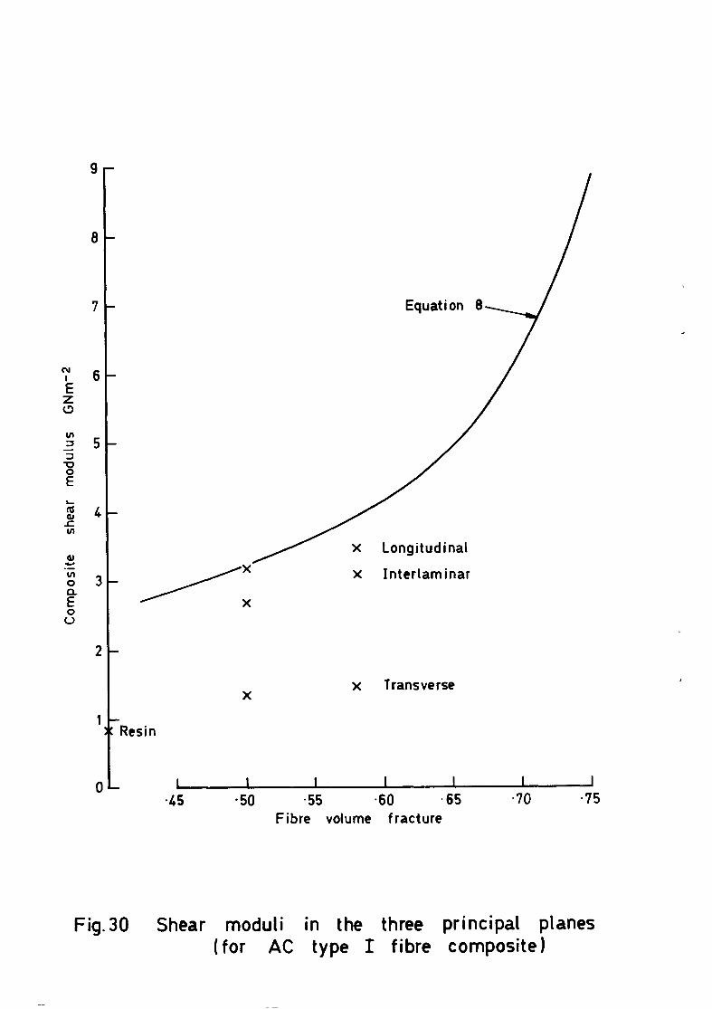
8-
l- I( Resin
X Transverse
O- 1 1 I I I I I I I I I I I I -45 -45 -50 -50 -55 -55 -60 -60 365 365 -70 -70 -75 -75
Fibre volume fracture Fibre volume fracture
Fig.30 Shear moduli in the three principal planes (for AC type I fibre composite)


. .

140 -
120 -
100 -
OL .
0
- 0
estimated
/ .- - regression
\
\
\t
L I I I 1 4
45 *so l 55 a60 ,65 *70
Fibre volume fractions-v
Fig. 34 Variation of shear strength with fibre content. Short beam -Type I

140-
20
0 L 1 1 I I I I -45 -50 -55 -60 -65 *70
Fibre volume fractions -v
Fig. 35 Variation of shear strength with fibre content. Transverse compression-Type II

1
0
I
N 0
I
Composite shear strength MNrii’
*r G is 0 z z 0 0 6 I I I I I 1
I
D D
D D

100
20
0
- **:: ‘/o
- 0
\ 0
0
- .
1 I I I I 1 -
l 45 -50 -55 l 60 l 65 l 70
Fibre volume fraction - v
Fig. 3 7 Variation of shear strength with fibre content. Short beam -Type II

-l-l tz’ . w co
nJ rc -.
Composite shear strength MNni*

140
120
100
80
60
40
20
0 2 4 6 8
Void content -V%
10 12
Fig. 39 Effect of voids on shear strength. Rail -Type I

100
80
60
40
20
estimated regression
2 4 6 8 10 12
Void content - V%
Fig. 40 Effect of voids on shear strength. Short beam -Type I

0
0
l l l
l 0
l V, = 0.6
2 4 6
Void content -V%
8 10 12
Fig. 11 Effect of voids on shear strength. Transverse compression - Type I

40
20
4 6 0 10 12
Void content - V"io
Fig.42 Effect of voids on shear strength. Rail -Type II

20
4 6 8 10 12
Void content - V”b
Fig.43 Effect of voids on shear strength. Short beam -Type II

140
120
.
l
l
2(
0
a
2 4 6 8 10
Void content - V%
12
Fig. 11 Effect of voids on shear strength. Transverse compression - Type II

I -
I-
Transverse 0 compression 0 Sho;t I
Autoclave Type II fibre specimens uncorrected for Vv, but V, < 0*5%]
-45 -50 -55 -60 065 *70
Fibre volume fraction- v
Fig. 15 Variation of shear strength with fibre content. Type It
Prmted in England for Her Malcst,! ‘s Stationery Ojjice b.v thr Royal Awcrajt ITstabluhmcnt, Farnborough. Dd 587483 KS 717’

ARC CP No.1381 July 1976
Purslow, D.
THE SHEAR PROPERTIES OF UNIDIRECTIONAL CARBON FIBRE REINFORCED PLASTICS AND THEIR EXPERIMENTAL DETERMINATION
620.177.6
Various techniques for the prediction and measurement of the shear strength and stiff- ness of unidirectional carbon fibre composites have been compared and evaluated.
The Report concludes that the shear modulus, but not the shear strength, may be pre- dicted with sufficient accuracy for most practical purposes and recommends satisfac- tory methods for the experimental determination of shear modulus and strength.
------ -__- --- __-_--__- ----
ARC CP No.1381 July 1976
155;;:“” :
539:4& : Purslow, D. 539.557 :
620.176 : THE SHEAR PROPERTIES OF UNIDIRECTIONAL CARBON FIBRE REINFORCED PLASTICS AND THEIR EXPERIMENTAL DETERMINATION
620.177.6
Various techniques for the prediction and measurement of the shear strength and stiff- ness of unidirectional carbon fibre composites have been compared and evaluated.
The Report concludes that the shear modulus, but not the shear strength, may be pre- dicted with sufficient accuracy for most practical purposes and recommends satisfac- tory methods for the experimental determination of shear modulus and strength.
l - - . - - ------------------- ‘ - - -
;
I
I
I
I
I I
I
I I
I
I
I I
ARC CP No.1381 July 1976
Purslow. D. 620.176 :
THE SHEAR PROPERTIES OF UNIDIRECTIONAL CARBON FIBRE REINFORCED PLASTICS AND THEIR EXPERIMENTAL DETERMINATION
620.177.6
Various techniques for the prediction and measurement of the shear strength and stiff- ness of unidirectional carbon fibre composites have been compared and evaluated.
The Report concludes that the shear modulus, but not the shear strength, may be pm- dieted with sufficient accuracy for most practical purposes and recommends satisfac- tory methods for the experimental determination of shear modulus and strength.
-_------m-----e-- - - - - - - - - - - -
I I I I I
I I
I
I
I
I
I I
I
I
ARC CP No.1381 661.66426 : July 1976 678.046 :
Purdow, D. ;$4;;.2 :
620:176 i THE SHEAR PROPERTIES OF UNIDIRECTIONAL 620.177.6 CARBON FIBRE REINFORCED PLASTICS AND THEIR EXPERIMENTAL DETERMINATION
Various techniques for the prediction and measurement of the shear strength and stiff- ness of unidirectional carbon fibre composites have been compared and evaluated.
The Report concludes that the shear modulus, but not the shear strength, may be pm- dieted with sufficient accuracy for most practical purposes and recommends satisfac- tory methods for the experimental determination of shear modulus and strength.
1 __--------w---e---- - - - - - - - -
DETACHABLE ABSTRACT CARDS DETACHABLE ABSTRACT CARDS

C.P. No. 1381
1977
Published by HER MAJESTY’S STATIONERY OFFICE
Government Bookshops
49 High Holborn, London WCIV 6HB 13a Castle Street, Edinburgh EH2 3AR
41 The Hayes, Cardiff CFl IJW Brazennose Street, Manchester M60 8AS
Southey House, Wine Street, Bristol BSI 2BQ 258 Broad Street, Birmingham Bl 2HE 80 Chichester Street, Belfast BT1 4JY
Government Publications are also available through booksellers
C.P. No. 1381 ISBN 011 471127 5